JP4800636B2 - Image forming apparatus - Google Patents
Image forming apparatusInfo
- Publication number
- JP4800636B2 JP4800636B2 JP2005040770A JP2005040770A JP4800636B2 JP 4800636 B2 JP4800636 B2 JP 4800636B2 JP 2005040770 A JP2005040770 A JP 2005040770A JP 2005040770 A JP2005040770 A JP 2005040770A JP 4800636 B2 JP4800636 B2 JP 4800636B2
- Authority
- JP
- Japan
- Prior art keywords
- image
- recording medium
- unit
- image forming
- transfer
- Prior art date
- Legal status (The legal status is an assumption and is not a legal conclusion. Google has not performed a legal analysis and makes no representation as to the accuracy of the status listed.)
- Expired - Fee Related
Links
Images


Landscapes
- Developing Agents For Electrophotography (AREA)
- Fixing For Electrophotography (AREA)
- Paper Feeding For Electrophotography (AREA)
- Electrophotography Configuration And Component (AREA)
- Electrostatic Charge, Transfer And Separation In Electrography (AREA)
- Control Or Security For Electrophotography (AREA)
Description
本発明は、感光体に形成されたトナー画像を転写紙等の転写材に転写し、転写トナー像を定着する定着装置、画像形成装置に関するものである。 The present invention relates to a fixing device and an image forming apparatus that transfer a toner image formed on a photoreceptor to a transfer material such as transfer paper and fix the transferred toner image.
従来、転写紙の表裏両面に画像を記録させる方式として、一度定着装置を通過させた転写紙を反転させ、再度転写紙の別の面にトナーを転写させ定着させる方式が一般的に使用されている。 Conventionally, as a method for recording images on both the front and back sides of a transfer paper, a method is generally used in which the transfer paper once passed through the fixing device is reversed and the toner is transferred to another side of the transfer paper and fixed again. Yes.
ところが、この方式では、転写紙の搬送方向切り換えや、一度転写紙が定着装置を通って加熱・加圧されることによって転写紙にカールが発生するため、搬送の信頼性確保に多くの課題を有している。 However, in this method, the transfer paper is changed in the transport direction, and once the transfer paper is heated and pressurized through the fixing device, the transfer paper is curled. Have.
このような不具合を解消する方式として、例えば、特許文献1に開示されたものがある。この方式は転写紙の両面にトナー像を形成した後、1回で定着を行うものである。
As a method for solving such a problem, for example, there is one disclosed in
詳細には、感光体上に形成した第1の画像を第1の転写手段で転写ベルトに転写し、次いで、感光体上に形成した第2の画像を第1の転写手段で転写紙の一面に転写する。その後、転写ベルト上の第1の画像を第2の転写手段で転写紙の他面に転写することで転写紙の両面に画像を転写し、定着するものである。 Specifically, the first image formed on the photoconductor is transferred to the transfer belt by the first transfer unit, and then the second image formed on the photoconductor is transferred to one side of the transfer paper by the first transfer unit. Transcript to. Thereafter, the first image on the transfer belt is transferred to the other surface of the transfer paper by the second transfer means, whereby the image is transferred and fixed on both sides of the transfer paper.
しかし、特許文献1の方式では、未定着の画像を持った転写紙の先端が転写ベルトから搬出されて定着装置に搬入されるまで、転写紙の先端がフリーの状態になるため、未定着のトナー像が乱れてしまう。
However, in the method of
このため、特許文献2のように転写紙の両面にトナー像を転写した後、定着装置に転写紙を搬送するものにおいて、その搬送路に拍車を設置して未定着のトナー像乱れを防止するようにすることが考えられる。
For this reason, in the case where the toner image is transferred to both surfaces of the transfer paper as in
しかし、特許文献2のように搬送路に拍車を設置して未定着のトナー像乱れを防止する場合には、未定着のトナー像を担持した転写紙を定着装置まで搬送する拍車が経時的にトナーで汚れ、画像にそのトナーが移り、結果として、画像品質を劣化させてしまう。また小型化を目的に縦型搬送を採用すると記録媒体の腰の強さ等から更に搬送品質まで落ちる結果になる。
However, when a spur is installed in the conveyance path as in
本発明は、前記事情に着目してなされたものであり、その目的とするところは、記録媒体の搬送速度を一定にして搬送時の画像劣化を防止し高画質化を達成した画像形成装置を提供することにある。 The present invention has been made paying attention to the above circumstances, and an object of the present invention is to provide an image forming apparatus that achieves high image quality by preventing the image deterioration during conveyance by keeping the conveyance speed of the recording medium constant. It is to provide.
前記課題を解決するために、請求項1に記載された発明は、画像形成装置であって、第1画像形成ユニットで形成される第1画像を第1像担持ベルトに担持させることが可能な第1像担持ユニットと、第2画像形成ユニットで形成される第2画像を第2像担持ベルトに担持させることが可能な第2像担持ユニットと、前記第1像担持ユニットが担持する前記第1画像を記録体の第1の面に転写させるための第1転写手段を含む第1転写ステーションと、前記第2像担持ユニットが担持する前記第2画像を記録体の第2の面に転写させるための第2転写手段を含む第2転写ステーションと、前記第1、第2転写ステーションの間に記録体を供給、搬送させる手段を含む記録体搬送路と、前記第1、第2転写ステーションの間を出た記録体を加熱定着装置まで搬送する、無端ベルト状に構成された搬送手段と、前記搬送手段の外側に、クリーニング装置、前記記録体を吸着させるための吸着用チャージャ及び除電・分離チャージャと、両面の画像を定着させる加熱定着装置とを備え、前記吸着用チャージャは、搬送手段の表面を、前記第1画像及び前記第2画像を形成する現像剤の極性と同じ極性で帯電させるものであり、前記第2像担持ユニットの速度は前記第1像担持ユニット速度の出力により決定し、前記搬送手段は前記第2像担持ユニットの速度を検出し速度を決定し、前記加熱定着装置は前記搬送手段の速度を検出して速度を決定することにより、記録体の搬送速度を常に一定に制御することを特徴とする。
In order to solve the above-mentioned problem, the invention described in
また、請求項2に記載された発明は、請求項1に記載された発明において、前記第1像担持ユニットの駆動装置、前記第2像担持ユニットの駆動装置、前記搬送手段の駆動装置及び前記加熱定着手段の駆動装置が個別に備わっていることを特徴とする。 According to a second aspect of the present invention, in the first aspect of the present invention, the first image carrying unit driving device , the second image carrying unit driving device , the conveying means driving device, and driving device for heating the fixing means, characterized in that inherent in the individual.
また、請求項3に記載された発明は、請求項1に記載された発明において、記録体の種類によって速度を制御したことを特徴とする。
The invention described in
また、請求項4に記載された発明は、請求項1に記載された発明において、前記定着装置の速度を記録体の種類によって制御することを特徴とする。 According to a fourth aspect of the present invention, in the first aspect of the present invention, the speed of the fixing device is controlled according to the type of the recording medium.
また、請求項5に記載された発明は、請求項1に記載された発明において、坪量90g/m2以上の記録体の使用時は定着装置の速度を1/2にしたことを特徴とする。
The invention described in
また、請求項6に記載された発明は、請求項1に記載された発明において、坪量90g/m2以上の記録体の使用時は前記搬送手段の速度を1/2にしたことを特徴とする。
The invention described in claim 6 is characterized in that, in the invention described in
また、請求項7に記載された発明は、請求項1に記載された発明において、前記第2像担持ベルトの速度切り替えは記録体が第2転写手段を通過した後であることを特徴とする。
The invention described in claim 7 is characterized in that, in the invention described in
また、請求項8に記載された発明は、請求項1に記載された発明において、前記搬送手段の搬送部の長さLは最大画像長さ以上であることを特徴とする。
The invention described in claim 8 is characterized in that, in the invention described in
また、請求項9に記載された発明は、請求項1に記載された発明において、前記搬送手段が耐熱ベルトであることを特徴とする。
The invention described in claim 9 is the invention described in
また、請求項10に記載された発明は、請求項1に記載された発明において、前記搬送手段の材質がポリイミドであること特徴とする。
The invention described in claim 10 is the invention described in
また、請求項11に記載された発明は、請求項1に記載された発明において、前記搬送手段の体積抵抗値は、106〜1012Ωcmであること特徴とする。
The invention described in claim 11 is characterized in that, in the invention described in
また、請求項12に記載された発明は、請求項1に記載された発明において、前記記録体搬送路における記録体の搬送方向上流に、該記録体搬送路とほぼ同じ給紙供給面から記録体を供給可能な給紙装置を備えることを特徴とする。 According to a twelfth aspect of the present invention, in the invention described in the first aspect, recording is performed from substantially the same sheet supply and supply surface as the recording medium conveyance path upstream of the recording medium conveyance path in the recording medium conveyance path. A sheet feeding device capable of supplying a body is provided.
また、請求項13に記載された発明は、請求項12に記載された発明において、記録体搬送路が給紙部の給紙面から前記加熱定着装置のニップ部までほぼ同一面であることを特徴とする。 According to a thirteenth aspect of the present invention, in the invention according to the twelfth aspect , the recording material conveyance path is substantially the same surface from the paper feed surface of the paper feed portion to the nip portion of the heat fixing device. And
また、請求項14に記載された発明は、請求項1に記載された発明において、前記第1転写ステーションと第2転写ステーションにおいて、前記第1像担持ベルトと第2像担持ベルトが非接触であり、それぞれの転写ステーションに配備される転写手段のうち、記録体搬送方向において上流に配備した転写手段には、バイアス印加可能の転写ローラを採用したことを特徴とする。
Further, the invention described in claim 14, in the invention described in
また、請求項15に記載された発明は、請求項1に記載された発明において、使用するトナーの平均円形度が0.90〜0.99であることを特徴とする。
The invention described in claim 15 is the invention described in
また、請求項16に記載された発明は、請求項1に記載された発明において、使用するトナーの形状係数SF−1が120〜180であり、形状係数SF−2が120〜190であることを特徴とする。
The invention described in claim 16 is the invention described in
また、請求項17に記載された発明は、請求項1に記載された発明において、使用するトナーのDv/Dn〔Dvは体積平均粒径(μm)、Dnは個数平均粒径(μm)〕が1.05〜1.30であることを特徴とする。
The invention described in claim 17 is the invention described in
本発明によれば、記録体を転写部と定着装置の定着ニップまでの間に搬送手段を設け、全ての搬送速度を一定にすることで、両面の未定着画像を乱すことなく高品質な画像を形成することができる(両面の未定着像を画像劣化なく定着部に搬送することができる)。 According to the present invention, a high-quality image can be obtained without disturbing the unfixed images on both sides by providing a conveying means between the transfer unit and the fixing nip of the fixing device and making all the conveying speeds constant. (Unfixed images on both sides can be conveyed to the fixing unit without image deterioration).
以下、図面を参照しながら、本発明の一実施形態について説明する。 An embodiment of the present invention will be described below with reference to the drawings.
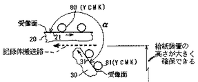
図1に示す画像形成装置本体100の内部において、記録体搬送路43Aを境にして、上部には矢印方向に無端移動する第1像担持ベルト21を備えた第1像担持体ユニット20を、下部には矢印方向に無端移動する第2像担持ベルト31を備えた第2像担持体ユニット30が配備されている。第1像担持ベルト21の上部張架面には、4個の第1画像形成ユニット80Y、80C、80M、80Kが、第2像担持ベルト31の傾斜した張架面には、4個の第2画像形成ユニット81Y、81C、81M、81Kが配備されている。これら第1、第2画像形成ユニットの番号に沿えたY、C、M、Kは、扱うトナーの色と対応させているもので、Yはイエロー、Cはシアン、Mはマゼンタ、Kはブラックを意味している。第1、第2画像形成ユニットに備えられ、第1像担持ベルト21と第2像担持ベルト31とともに回転する感光体1に対しても同じ意味あいでY、C、M、Kを沿えている。尚感光体1Yから1Kは同間隔で配置され、少なくとも画像形成時にはそれぞれ像担持ベルト21、31との張架部の一部と接触する。この接触する面を受像面と呼び、互いの位置関係を図2に示す。
In the image forming apparatus
扱うトナーの色は異なるが、第1画像形成ユニット80Y、80C、80M、80Kの構成は同じであるので、代表として第1画像形成ユニット80の構成を図3により説明する。
Although the toner colors to be handled are different, the configurations of the first
図3において、画像形成装置100の動作時に、不図示の駆動源により、矢印方向に回転するよう回転可能に支持された円筒状の感光体1の周囲に、静電写真プロセスに従い帯電手段であるスコロトロンチャージャ3、露光装置4、現像装置5、クリーニング装置2、光除電装置Q等の作像部材や電位センサS1、画像センサS2が配設されている。
In FIG. 3, during the operation of the
感光体1は、例えば直径30〜120mm 程度のアルミニウム円筒表面に光導電性物質である有機感光層(OPC)を形成したものである。アモルファスシリコン(a-Si)層を形成した感光体も採用可能である。またベルト状の感光体も採用できる。クリーニング装置2は、クリーニングブラシ2a、クリーニングブレード2b、回収部材2cを備え、感光体表面に残留するトナー等の異物を除去、回収する。
The
露光装置4は、各色毎の画像データ対応の光を、帯電手段で一様に帯電済みの各感光体1の表面に走査し、静電潜像を形成する。図示例の露光装置4は、発光素子としてLED(発光ダイオード)アレイと結像素子からなる露光装置であるが、レーザ光源、ポリゴンミラー等を用い、形成すべき画像データに応じて変調したビーム光によるレーザスキャン方式の露光装置も採用できる。
The
帯電手段として、チャージャ3のほかに、感光体1の表面に接触させるタイプ、例えば帯電ローラも採用できる。
As the charging means, in addition to the
本実施例の現像は、トナーとキャリヤからなるニ成分現像剤を採用している現像方式である。負荷電の感光体1に対しレーザビームにより各感光体1の表面に形成された色毎の静電潜像は、感光体お帯電極性と同極性(マイナス極性)の所定の色のトナーで現像され、顕像となる。いわゆる反転現像が行われる。
The development in this embodiment is a development system that employs a two-component developer composed of toner and carrier. The electrostatic latent image for each color formed on the surface of each
イエロー(Y)、シアン(C)、マゼンタ(M)、ブラック(K)の各色トナーは、各色を扱う現像装置で消費されると、透磁式のトナー検知手段5eにより検知され、画像形成装置100内部のトナーカートリッジ収納部85に備えるトナーカートリッジ86から、不図示の供給手段により、各色のトナーを各現像装置5に供給される。
When each color toner of yellow (Y), cyan (C), magenta (M), and black (K) is consumed by a developing device that handles each color, the toner is detected by the magnetically permeable
この供給手段として、公知のモーノポンプを用いる方式のものが採用できる。この方式によればトナーカートリッジの設置場所の制約が少ないため、画像形成装置内部のスペース配分に対し有利である。またトナーが適時補給できるため、現像装置に大きなトナー貯留スペースを設けなくてすみ、現像装置の小型化がはかれる。 As this supply means, a system using a known MONO pump can be adopted. According to this method, there are few restrictions on the installation location of the toner cartridge, which is advantageous for space allocation in the image forming apparatus. Further, since the toner can be replenished in a timely manner, it is not necessary to provide a large toner storage space in the developing device, and the developing device can be downsized.
現像装置5には、トナーとキャリヤの攪拌、搬送用のスクリュー5cや5dが備えてある。現像装置5が画像形成装置100に装着されているとき、上記トナー補給手段の一端が、スクリュー5dの一部に接続されている。スクリュー5cによりトナーは、矢印方向に回転する現像ローラ5aに供給されるが、ブレード5bにより、現像ローラ5a表面のトナー層の厚みは、所定の厚みになるよう規制される。現像ローラ5aは、ステンレスやアルミニュウム製の円筒で、回転可能にかつ感光体との距離が正規に確保されるように現像装置5のフレームに支持され、内部には所定の磁力線が構成されるようにマグネットが備えてある。尚使用するトナーは平均円形度が0.90〜0.99、形状係数SF−1が120〜180、形状係数SF−2が120〜190でありDv/Dnが1.05〜1.30である。〔Dvは体積平均粒径(μm)、Dnは個数平均粒径(μm)〕
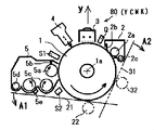
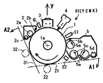
第2の像担持体ユニット30に使われる第2の画像形成ユニット81Y〜81Kについても、代表して第2の画像形成ユニット81として、図4により説明する。
The developing
The second image forming units 81Y to 81K used in the second
図4に示した第2の画像形成ユニット81は、第1の画像形成ユニット80と構成部材が同じであるが、図3のものと比べ感光体1の回転方向が異なっている。しかし互いに、図中の矢印で示す感光体1の回転軸1aを通るy軸に対し対象の形をしている。この形状は、感光体1の周囲に配備する画像形成用部材の配置にも関係するが、重要な事項である。つまり画像形成装置100との結合部、たとえば駆動手段との結合部、電気的接続部、トナー供給部、トナー排出部の結合方法を配慮しておけば、第1の画像形成ユニット80Y〜80Kと、第2の画像形成ユニット81Y〜81Kとに互換性をもたせることができる。従って第1の画像形成ユニットと第2の画像形成ユニット用に個別に現像装置、クリーニング装置、部品を製造する必要がなく、部品製造、部品の管理上での効率が高く、全体のコスト低減がはかれる。
The second
第1と第2の画像形成ユニットをy軸中心にした軸対象の形で、第1の像担持体ユニット20と第2の像担持体ユニット30で使用できる第1条件として、感光体1の周囲で画像形成のための部材を配備していない周面が確保されていること、つまり像担持ベルトが当接可能な範囲が広く確保されていること。そして第2条件として、第1の像担持ベルト21と第2の像担持ベルト31の配置角度が適切であることがあげられる。
As a first condition that can be used by the first
上記の第1条件、第2条件について図3、図4により説明する。図3あるいは図4において、像担持ベルト21あるいは31は、矢印A1とA2の間に設置可能である。つまりA1側は現像装置5で、A2側はクリーニング装置2にベルトが接触しない範囲に像担持ベルトが設置できることを示している。図3に第2の像担持ベルト31を含めているのは、感光体1の回転軸1aを含むy軸に対し対象の画像形成ユニットが配置できる像担持ベルトを示している。もし、画像形成ユニット80をy軸に直交する軸を対象に上下反転して画像形成ユニット81として使うとすると、地球重力の影響があり、少なくとも現像装置5において、トナーの攪拌、現像ローラ5aへのトナー補給等の条件は異なり、それぞれ最適化しなければならず、部品の共通化も不可能となる。
The above first condition and second condition will be described with reference to FIGS. 3 or 4, the
図2に示すように、第1像担持ベルト21の受像面に対し第2像担持ベルト31の受像面との位置関係として角度αを180度を越え270度、好ましくは210度から255度としたとき、画像形成ユニットとして、第1像担持ベルトには図3に示す形態、第2像担持ベルトには図4に示す形態のものが採用できる。つまり上記のごとく部品の共通化を不可能にしてしまう画像形成ユニットとなることが回避できた。
As shown in FIG. 2, the positional relationship between the image receiving surface of the first
また、図2のように、第2の画像形成ユニット81の上方に、記録体搬送路をほぼ水平にかつ直線的に確保できるので、記録体の搬送・信頼性に優れ、画像形成装置全体のまとまりが良好となる。
Further, as shown in FIG. 2, since the recording medium conveyance path can be secured almost horizontally and linearly above the second
特に、第1の像担持ベルトを水平方向に長く、扁平に張架し、第2像担持ベルトを縦方向に長くかつ傾斜させて張架したので、記録体搬送路を境にして下方に第2像担持ベルトの高さ方向のスペースが大きくなるが、この第2像担持ベルトの占める高さとほぼ同じ高さの給紙装置が並べて設置できる。これにより大量の用紙が収納可能な給紙装置が設置でき、しかも給紙装置の上面の給紙面と記録体搬送路とがほぼ同じ高さにでき、用紙の給紙・搬送信頼性が確保できる。 In particular, the first image bearing belt is stretched horizontally and flatly, and the second image bearing belt is stretched long and inclined in the longitudinal direction. Although the space in the height direction of the two-image carrying belt becomes large, it is possible to install a sheet feeder having a height substantially the same as the height occupied by the second image-carrying belt. As a result, a paper feeding device capable of storing a large amount of paper can be installed, and the paper feeding surface on the upper surface of the paper feeding device and the recording material conveyance path can be made substantially the same height, thereby ensuring the paper feeding / conveying reliability. .
複数のローラ23,24,25、26(2個)、27、28、29により支持されて矢印方向に走行する、像担持体としての第1像担持ベルト21が、第1の画像形成ユニット80Y〜80Kにおける感光体1Y,1C,1M,1Kの下部に設けられている。この像担持ベルト21は無端状で、各感光体の現像工程後の一部が接触するように張架、配置されている。また第1像担持ベルト21の内周部には各感光体1Y,1C,1M,1Kに対向させて1次転写ローラ22が設けられている。
A first
第1像担持ベルト21の外周部には、ローラ23に対向する位置にクリーニング装置20Aが設けられている。このクリーニング装置20Aは、像担持ベルトベルト21の表面に残留する不要なトナーや、紙粉などの異物を拭い去る。
A
上記の像担持ベルト21に関連する部材は、第1像担持体ユニット20として一体的に構成してあり、画像形成装置100に対し着脱が可能となっている。
The members related to the
複数のローラ33、34、35、36(2個)、37、38により支持されて矢印方向に走行する、像担持体としての第2像担持ベルト31が、第2の画像形成ユニット81Y〜81Kにおける感光体1Y,1C,1M,1Kに接触して、設けられている。この像担持ベルト31は無端状で、各感光体の現像工程後の一部が接触するように張架、配置されている。像担持ベルト31の内周部には各感光体1Y,1C,1M,1Kに対向させて1次転写ローラ32が設けられている。
A second
第2像担持ベルト31の外周部には、ローラ33に対向する位置にクリーニング装置30Aが設けられている。このクリーニング装置30Aは、像担持ベルトベルト31の表面に残留する不要なトナーや、紙粉などの異物を拭い去る。
A
上記の像担持ベルト31に関連する部材は、第2像担持体ユニット30として一体的に構成してあり、画像形成装置100に対し着脱が可能となっている。
The members related to the
ここで、像担持ベルトの構成、材質について説明する。像担持ベルト21、31は、例えば、基体の厚さが50〜600μmの樹脂フィルム或いはゴムを基体とするベルトであって、各感光体1が担持するトナー像を、1次転写ローラ22、32に印加するバイアスにより静電的にベルト表面に転写を可能とする抵抗値を有する。一つの実施形態として、ポリアミドにカーボンを分散し、その体積抵抗値は、106〜1012Ωcm程度に抵抗が調整されたものである。ベルトの走行を安定させるためのベルト寄り止めリブを、ベルト片側あるいは両側端部に設けてある。
Here, the configuration and material of the image bearing belt will be described. The
搬送ベルト51は例えば、基体の厚さが50〜600μmの樹脂フィルム或いはゴムを基体とするベルトであって、印加するバイアスにより静電的にベルト表面に記録体が密着が可能となる抵抗値を有するものである。一つの実施形態として、ポリアミドにカーボンを分散し、その体積抵抗値は、106〜1012Ωcm程度に抵抗が調整されたものである。 The transport belt 51 is, for example, a belt based on a resin film or rubber having a base thickness of 50 to 600 μm, and has a resistance value that enables the recording medium to be electrostatically adhered to the belt surface by an applied bias. It is what you have. In one embodiment, carbon is dispersed in polyamide, and the volume resistance value is adjusted to a resistance of about 10 6 to 10 12 Ωcm.
ベルトの走行を安定させるためのベルト寄り止めリブを、ベルト片側あるいは両側端部に設けてある。 Belt detent ribs for stabilizing the running of the belt are provided on one side or both ends of the belt.
1次転写ローラの構成に関しては、一つの実施形態として、1次転写ローラ22、32は芯金たる金属ローラの表面に、導電性ゴム材料を被覆したもので、芯金部に、不図示の電源からバイアスが印加される。導電性ゴム材料はウレタンゴムにカーボンが分散され、体積抵抗105Ωcm程度に抵抗が調整されている。
Regarding the configuration of the primary transfer roller, as one embodiment, the
ブラックトナーだけによるモノクロ記録も可能である。このようなケースにあっては、使用されない感光体が存在する。そこで使用されない感光体1Y、1C、1Mあるいは現像装置5を稼動させないだけでなく、これら使用されない感光体と像担持ベルト21あるいは31とを非接触に保つための機構を備えている。本実施の形態では、ローラ26と1次転写ローラ22を支持する内部フレーム(不図示)を設けておき、ある点を中心に回動可能に支持し、感光体から遠ざかる方向に回動させることにより、感光体1Kだけが像担持ベルト21あるいは31と接触して、作像工程を実行することにより、ブラックトナーによるモノクロ画像を作成する。感光体の寿命向上の点で有利である。
Monochrome recording using only black toner is also possible. In such a case, there are photosensitive members that are not used. Therefore, not only the unused photoreceptors 1Y, 1C, 1M or the developing
更に上記第1像担持ベルト21の外周で、支持ローラ28の近傍には、第1の2次転写ローラ46が設けてある。2次転写ローラ46は芯金たる金属ローラの表面に、導電性ゴムを被覆したもので、芯金部に、不図示の電源からバイアスが印加される。上記ゴムにはカーボンが分散されており、体積抵抗は107Ωcm程度に抵抗が調整されたものである。第1像担持ベルト21と2次転写ローラ46の間に記録媒体(以下用紙P)を通過させながら、第1の2次転写ローラ46にバイアスを印加することで第1像担持ベルト21が担持するトナーによる画像が記録体Pに転写される。
Further, a first secondary transfer roller 46 is provided in the vicinity of the support roller 28 on the outer periphery of the first
上記第2像担持ベルト31の外周で、支持ローラ34の近傍には、第2の2次転写手段である転写チャージャ47が設けてある。転写チャージャ47は公知のタイプで、タングステンや金の細い線を放電電極とし、ケーシングで保持し、放電電極に不図示の電源から転写電流が印加される。像担持ベルト31と転写チャージャ47の間に記録体Pを通過させながら、転写電流を印加することで第2像担持ベルト31が担持するトナーによる画像が記録体Pに転写される。上記転写ローラ46と転写チャージャ47に印加される転写電流の極性は、共にトナーの極性と逆のプラス極性である。
A transfer charger 47 serving as a second secondary transfer unit is provided on the outer periphery of the second
画像形成装置100の右側には用紙を供給可能に収納した給紙装置40が配備されている。複数段、例えば上段に大量の用紙を収納した給紙装置(トレイ)40a、その下方に3段の給紙カセット40b,40c、40dがそれぞれ紙面に対し直角手前側(操作面側)に引出し可能に配設されている。これらの給紙トレイ40aや給紙カセット40b,40c、40d内に収納された用紙Pのうち、最上位置の用紙は、対応する給紙・分離手段41A〜41Dにより選択的に給紙、分離され、確実に一枚だけが複数の搬送ローラ対42Bにより記録体搬送経路43Bや43Aに送られる。
On the right side of the
記録体搬送経路43Aには、2次転写位置へ用紙Pを送り出す給送タイミングをとるため、一対のレジストローラ45が設けられている。更に用紙の搬送方向に対し直角方向の位置を正規の位置にするためのジョガー44が、記録体搬送経路43Aに設けてある。ジョガー44は、用紙の搬送方向に対し両側から用紙の端部に向け移動するガイド部材を備えていて、走行中の用紙の両側からガイドが用紙を一瞬押しつけることで用紙を所定の位置に整合させる。
A pair of registration rollers 45 are provided in the recording
用紙Pは、レジストローラ対45から、第1像担持ベルト21と二次転写ローラ46で構成される第1の転写ステーションたる転写領域に向けて搬送される。その後、第2像担持ベルト31と転写チャージャ47で構成される第2の転写ステーションたる転写領域に向けて搬送される。
The sheet P is transported from the registration roller pair 45 toward a transfer area serving as a first transfer station including the first
尚、搬送ローラ対42Cを有する記録体搬送路43Cには、その搬送方向上流に設置可能な別の給紙装置300から、用紙が供給可能となっている。給紙トレイ40aの最上位の用紙が給紙され、その後曲げられることなく、ほぼ水平に真直ぐ搬送されるように、給紙トレイ40aの上部給紙面が配備してある。そのため厚い用紙、剛性の高い板紙でも確実に給紙できる。尚給紙トレイ40aには、多様な特性の用紙が収納されても確実に給紙できるよう、バキューム機構からなるエアー給紙を採用すると好都合である。図示していないが、記録体搬送路の要所には用紙を検知するためのセンサが具備させていて、用紙の存在を基準とする各種信号のトリガーとしている。
Note that the recording medium conveyance path 43C having the
記録体搬送路43Aの延長上に、前記第2の転写ステーションを通過した用紙を、記録体の搬送方向下流に備えた加熱定着装置60における定着ニップまで、平面状態を保って搬送させるための、記録体移送手段50を備えている。記録体移送手段50は、矢印方向に無端移動する搬送ベルト51を支持するローラ52、53,54,55,56を有し、搬送ベルト51の外側には、ローラ55に対向させてクリーニング装置50A,ローラ56に対向させて記録体Pを吸着させるための吸着用チャージャ57、ローラ57に対向させて除電・分離チャージャ58を備えている。
In order to convey the sheet that has passed through the second transfer station on the extension of the recording
未定着のトナー画像と接触しながら記録体Pとともに移動する搬送ベルト51は、前記吸着用チャージャ57により、トナーの極性と同極性のマイナス帯電が施される。搬送ベルト51として、ポリイミドベルトが採用できる。表面にトナーとの離型性を与えると共に、帯電可能の抵抗値を備える。
The conveyance belt 51 that moves together with the recording medium P in contact with the unfixed toner image is negatively charged by the
記録体搬送手段50の用紙搬送方向下流側には、加熱手段を有する定着装置60が設けられている。ローラ内部にヒータを備えるタイプ、加熱されるベルトを走行させるベルト定着装置、また加熱の方式に誘導加熱を採用した定着装置などが採用できる。本実施例ではベルトを走行させるものでベルト搬送ローラに加熱体としてヒータH1,H2が配置されている。用紙両面の画像の色合い、光沢度を同じにするため、定着ローラ、定着ベルトの材質、硬度、表面性などを上下同等にしてある。定着の終了した用紙を冷却し、不安定なトナーの状態を早期に安定させるため、冷却機能を有した冷却ローラ対70を定着後の搬送路に備えている。放熱部を有するヒートパイプ構造のローラが採用できる。冷却された用紙は、排紙ローラ対71により、画像形成装置100の左側に設けた排紙スタック部75に排紙、スタックさせる。この排紙スタック部は、大量の用紙をスタック可能にするため、不図示のエレベータ機構により、スタックレベルに応じて、受け部材が上下する機構を採用している。尚排紙スタック部75を通過させ、別の後処理装置に向けて用紙を搬送させることもできる。別の後処理装置としては、穴あけ、断裁、折、綴じなど製本のための装置である。
A fixing
未使用のトナーが収納された各色のトナーカートリッジ86Y,86C,86M、86Kが、着脱可能に空間85に収納される。不図示のトナー搬送手段により、各現像装置に必要に応じトナーを供給するようになっている。本実施例の構成は、上下に配された画像形成ユニット80、81に対し、トナーカートリッジは共通にしているが、別々にすることもできる。消耗の多いブラックトナー用のトナーカートリッジ86Kを、特に大容量としておくことも可能である。この収納空間85は、画像形成装置上面で操作方向から見て奥側にあって、画像形成装置上面の手前側は平面部分が確保されているため、作業台として利用できる。
The
画像形成装置100の上面に備えた操作、表示ユニット90には、キーボード等が備えてあり、画像形成のための条件などがインプットできるし、装置の状態等を表示部に表示され、操作者と画像形成装置との情報交換を容易なものとする。
The operation provided on the upper surface of the
画像形成装置100内部に備える廃トナー収納部87は、画像形成ユニットのクリーニング装置2、像担持ベルトのクリーニング装置20Aと30A、および搬送ベルト51のクリーニング装置50Aと連結されており、一括して廃トナーや紙粉等の異物を回収して収納する。上記のクリーニング装置(2、20A,20B、50A)に大容量の廃トナー収納部を備えないため、各クリーニング装置が小型にでき、さらに廃トナーの廃棄の操作性も良好となっている。満杯センサ(不図示)を使って廃トナー収納部87内のトナー廃棄、あるいは容器交換などの警告を発する。
The waste
また、画像形成装置100内部に備える電装・制御装置95には、各種電源や制御基板などが板金フレームに保護され収納されている。
In the electrical /
加熱定着装置60による熱や電装装置からの発熱により、画像形成装置内部は高温になるが、その対策としてファンFを設けて、内部部材の熱による機能低下を防止している。またこのファンFは冷却ローラ対70の放熱部と結合してあり、冷却ローラ対70の冷却効果を確実にしている。尚、参照符号200は原稿読取装置、300は追加設置が可能の給紙装置である。
The inside of the image forming apparatus becomes hot due to heat from the
次に、搬送速度について説明する。 Next, the conveyance speed will be described.
第1像担持ユニット20、第2像担持ユニット30、搬送手段50、加熱定着装置60にはそれぞれ単独で駆動装置(モーター)(M)を持ち、その軸にはエンコーダ(不図示)を備え回転出力を検出できる構成を取っている。
The first
本装置は両面が未定着像の記録体を転写から定着まで搬送するため搬送時の速度変動が画像に与える影響が大きい。特に加熱定着装置と搬送手段の速度差は影響が大きく、速度差があると搬送ベルト51と記録体とのスベリが生じ画像が乱れる結果になる。本装置は上記問題を上流の速度を検出して下流の速度を制御することで解決している。 Since this apparatus transports a recording medium having an unfixed image on both sides from transfer to fixing, the influence of speed fluctuation during transport has a great influence on the image. In particular, the difference in speed between the heat fixing device and the conveying means has a large influence, and if there is a difference in speed, slippage between the conveying belt 51 and the recording medium occurs and the image is disturbed. This device solves the above problem by detecting the upstream speed and controlling the downstream speed.
すなわち、第2像担持ユニット30の速度は第1像担持ユニット20速度の出力を見て速度が決り、搬送手段50は第2像担持ユニット30の速度を検出し速度を決定し、加熱定着装置60は搬送手段50の速度を検出して速度を決めているため記録体の搬送速度は常に一定に制御されている。
That is, the speed of the second
次に、上記構成の動作について説明する。先ず最初に、上記の構成において、用紙Pの片面にフルカラー画像を形成する片面記録時の動作について説明する。 Next, the operation of the above configuration will be described. First, the operation during single-sided recording in which a full-color image is formed on one side of the paper P in the above configuration will be described.
片面記録の方法は基本的に2種類あって、選択が可能となっている。2種類のうちの一つは、第1の像担持ベルト21に担持させた画像を用紙の片面に直接転写する方法であり、他の方法は、第2の像担持ベルト31に担持させた画像を用紙の片面に直接転写する方法である。本実施の形態では画像形成装置100の構成から、第1の像担持ベルト21に担持させた画像を用紙の片面に直接転写する場合には、画像が用紙の上面に、第2の像担持ベルト31に担持させた画像を用紙の片面に直接転写する場合には、画像が用紙の下面に形成される。記録するべきデータが複数の頁になるケースでは、排紙スタック部75上で頁が揃うように作像順序を制御するのが好都合である。最後の頁の画像データから順に記録して頁順を揃わせるよう、第1の像担持ベルト21に画像を担持させた後、用紙に転写させる方法について説明する。
There are basically two types of single-sided recording methods that can be selected. One of the two types is a method of directly transferring an image carried on the first
画像形成装置100を稼動させると、第1の像担持ベルト21と第1の画像形成ユニット80Y〜80Kにおける感光体1Y,1C、1M,1Kが回動する。同時に第2の像担持ベルト31が回動するが、第2の画像形成ユニット81Y〜81Kにおける感光体1Y,1C、1M,1Kは第2の像担持ベルト31と離間されるとともに不回転状態にされる。まず、画像形成ユニット80Yによる画像形成から開始される。LED(発光ダイオード)アレイと結像素子からなる露光装置4の作動により、LEDから出射されたイエロー用の画像データ対応の光が、帯電装置3により一様帯電された感光体1Yの表面に照射されて静電潜像が形成される。
When the
この静電潜像は現像ローラ5aによりイエロートナーで現像され、可視像となり、1次転写ローラ22の転写作用により感光体1Yと同期して移動する第1像担持ベルト21上に静電的に1次転写される。このような潜像形成、現像、1次転写動作が感光体1C,1M,1K側でもタイミングをとって順次同様に行われる。
This electrostatic latent image is developed with yellow toner by the developing
この結果、第1像担持ベルト21上には、イエロー、シアン、マゼンタ及びブラックの各色トナー画像が、順次重なり合ったフルカラートナー画像として担持され、第1像担持ベルト21とともに矢印の方向に移動される。
As a result, yellow, cyan, magenta, and black toner images are carried on the first
同時に給紙装置40のなかの給紙トレイ40aあるいは給紙カセット40b〜40dから、記録に使われる記録体Pがその供給のための給紙・分離手段41Aから41Dの一つにより繰り出され、搬送ローラ対42B,42Cにより記録体搬送路43Cに搬送される。記録体の先端がレジストローラ対45に咥えられない前に、ジョガー44は、記録体の搬送方向に対し両方の横方向から、記録体の両辺を押すように作動し、記録体横方向の位置整合がはかられる。レジストローラ対45は静止しており、記録体の先端はレジストローラ対45のニップに入り込んだ状態で静止するが、第1像担持ベルト21上の画像との位置が正規なものとなるよう、タイミングをとってレジストローラ対45が回転し、用紙を転写領域に搬送する。
At the same time, the recording medium P used for recording is fed from one of the
第1像担持ベルト21上のこのフルカラートナー画像は、第1像担持ベルト21と同期して搬送される用紙Pの上面に、二次転写ローラ46による転写作用を受けて転写される。二次転写ローラ46に与えられるバイアスは、トナーの帯電極性と逆のプラス極性である。
The full-color toner image on the first
その後、第1像担持ベルト21の表面が、ベルトクリーニング装置20Aによりクリーニングされる。また1次転写を終了した第1の画像形成ユニット80Y〜80Kにおける感光体1Y,1C、1M,1Kの表面に残留するトナー等の異物はクリーニング装置2のクリーニングブラシ2a、クリーニングブレード2bにより、各感光体の表面から除去される。各感光体の表面は除電装置Qによる残留電位の除電作用が行われて次の作像・転写工程に備える。除去されたトナー等の異物は、回収手段2cにより、回収部87に送られる。尚センサS1、S2は、感光体表面の露光後の表面電位と、現像工程後の感光体表面に付着しているトナーの濃度が適切なものであるかを検知し、適宜作像条件の設定、制御のために不図示の制御手段に情報を出す。
Thereafter, the surface of the first
像担持ベルト21に重ねられて担持されていたトナー画像が転写された記録体Pは、搬送装置50の搬送ベルト51により加熱定着装置60に向け移送される。記録体Pを確実に搬送ベルト51とともに移送できるよう、あらかじめ移送ベルト51の表面を、記録体の吸着用チャージャ57により帯電する。用紙Pが搬送ベルト51から分離され、確実に加熱定着装置60に送られるよ、除電・分離チャージャ58が作動する。
The recording material P to which the toner image that has been superposed and carried on the
記録体P上に重ねられていた各色のトナーが加熱定着装置60の熱による定着作用を受け、溶融、混色されて完全にカラー画像となる。定着されたトナーも用紙上で完全に固着するまでは、搬送路のガイド部材等にこすられ、画像が欠落したり、乱れたりする。この不具合を防止するため、冷却手段である冷却ローラ対70が作動し、トナーと用紙を冷却する。その後、排紙ローラ71により排紙スタック部75に、画像面が上向きとなって排紙される。排紙スタック部75では若い頁の記録物が順次上に重ねられるようにスタックされるよう、作像順序がプログラムされているので、頁順が揃う。排紙スタック部75は、排紙される記録体の増加に従って、下降するので、記録体は整然と確実にスタックでき、頁順が乱れることがない。記録済みの記録体を排紙スタック部75に直接スタックする代わりに、穴あけ加工処理を実施するとか、ソータ、コレータや綴じ装置や折り装置など後処理装置に搬送することもできる。
The toners of the respective colors superimposed on the recording medium P are subjected to a fixing action by the heat of the
記録体Pの片面に画像を形成させる他の方法では、第1の画像形成ユニット80Y〜80Kにおける画像の形成を行わないようにするのと、頁揃えのために若い頁の画像データから順に像形成をさせる点が異なるが、基本的には上記の片面記録の工程と同じなので、詳細を省く。 In another method of forming an image on one side of the recording material P, the image formation in the first image forming units 80Y to 80K is not performed, and the image data of the young pages is sequentially formed for page alignment. Although the formation is different, the details are omitted because it is basically the same as the one-side recording process described above.
次に、記録体Pの両面に画像を形成する両面記録時の動作について説明する。画像形成装置に開始信号が入力されると、上記、片面記録の動作で説明した第1の画像形成ユニット80Y、80C、80M、80Kで順次形成する各色ごとの画像を、第1像担持ベルト21に順次1次転写させ、第1の画像として担持させる工程とほぼ平行して、第2の画像形成ユニット81Y、81C、81M、81Kで順次形成する各色ごとの画像を第2像担持ベルト31に順次1次転写させ、第2の画像として担持させる工程が行われる。図1に示す構成なので、上記第1の画像と第2の画像が、用紙の搬送方向先端で位置的に合致するためには、第1の画像の形成開始より遅れて第2の画像の形成が開始される。また用紙はレジストローラ対45で静止と再送が行われるので、その時間も見込んで給紙され、ローラ42間で記録体表裏の表面粗さを測定機150,160で測定される。またジョガー44で整合される。レジストローラ対45は、タイミングをとって用紙を第1の2次転写手段である転写ローラ46と第1像担持ベルト21で構成された第1転写ステーションに搬送する。転写ローラ46にプラス極性の転写電流が印加され、第1像担持ベルトから用紙Pの片面(図では上面)に画像が転写される。
Next, the operation during double-sided recording in which images are formed on both sides of the recording medium P will be described. When a start signal is input to the image forming apparatus, the first
このようにして片面に画像を有した用紙Pは、転写ローラ46の搬送作用により、引き続き第2の二次転写手段たる転写チャージャ47のある第2転写ステーションに送られる。そしてチャージャにプラス極性の転写電流が印加されることにより、第2像担持ベルト31にあらかじめ担持されているフルカラーの第2の画像が、一括して用紙Pの下面に転写される。
Thus, the sheet P having an image on one side is continuously sent to the second transfer station having the transfer charger 47 as the second secondary transfer means by the transfer action of the transfer roller 46. Then, by applying a positive transfer current to the charger, the full-color second image previously carried on the second
このようにして両面にフルカラートナー像が転写された用紙Pは、搬送ベルト51により定着装置60へと移送される。吸着用チャージャにより、搬送ベルト51の表面はトナーの極性と同じマイナス極性で帯電される。用紙下面の未定着のトナーがベルトに移らないようにしている。除電・分離チャージャ58には、交流が印加され、用紙はベルト51から分離され、加熱定着装置60へと移送される。加熱定着装置60の熱による定着処理を受け、用紙の両面のトナー画像が溶融、混合される。用紙は引き続いて冷却ローラ対を通過し、排紙ローラ71により排紙スタック部75上に排紙される。
The paper P on which the full color toner images are transferred on both sides in this way is transported to the fixing
複数の頁の用紙に両面記録する場合、若い頁の画像が下面となって排紙スタック部75にスタックされるように作像順序を制御すると、そこから取り出し、上下面を逆にしたとき記録物は上から順に1頁、その裏に2頁、2枚目が3頁、その裏が4頁となり頁順が揃う。このような作像順序の制御や、定着装置に入力する電力を片面記録時より増やすなどの制御は、制御手段(不図示)により実行される。 When double-sided recording is performed on a plurality of pages of paper, the image formation order is controlled so that the image of a young page becomes the bottom surface and is stacked on the paper discharge stack unit 75. The order of the pages is 1 page in order from the top, 2 pages on the back, 3 pages on the second sheet, and 4 pages on the back. Such control of image forming sequence and control such as increasing the power input to the fixing device compared to the one-side recording are executed by a control means (not shown).
片面記録、両面記録動作に関して、フルカラー記録を実行させる例で説明したが、ブラックトナーだけによるモノクロ記録も可能である。 As for the single-sided recording and the double-sided recording operation, an example in which full-color recording is performed has been described.
尚、厚紙印刷の場合、坪量90g/m2を超す厚紙印刷の場合は本定着システムでは定着不足を発生させるため、前記厚紙の場合は定着不良を防止するためシステム速度を1/2に落として対応する。この場合、速度の切り替えは第2の転写手段を記録媒体が越えた後に切り換えられる。その時、記録媒体は定着手段のニップには入っていないことが条件になりそのため転写手段50から定着装置60のニップまでの距離を記録媒体の画像最大長さ以上確保している。
In the case of thick paper printing, in the case of thick paper printing with a grammage exceeding 90 g / m 2 , this fixing system will cause insufficient fixing. In the case of thick paper, the system speed is reduced by half to prevent fixing failure. Correspond. In this case, the speed is switched after the recording medium has passed the second transfer means. At that time, it is a condition that the recording medium does not enter the nip of the fixing unit. Therefore, a distance from the
以上説明したように、本実施形態の画像形成装置は、第1画像形成ユニット(80Y、C,M,K)で形成される第1画像を第1像担持ベルト21に担持させることが可能な第1像担持ユニット20と、第2画像形成ユニット81Y、C,M,Kで形成される第2画像を第2像担持ベルト31に担持させることが可能な第2像担持ユニット30と、前記第1像担持ユニットが担持する前記第1画像を記録体Pの第1の面に転写させるための第1転写手段46を含む第1転写ステーションと、前記第2像担持ユニットが担持する前記第2画像を記録体の第2の面に転写させるための第2転写手段47を含む第2転写ステーションと、前記第1、第2転写ステーションの間に記録体を供給、搬送させる手段42A,45などを含む記録体搬送路43Aと前記第1、第2転写ステーションの間を出た記録体を加熱定着装置60まで搬送する、無端ベルト状に構成された搬送手段50と両面の画像を定着させる加熱定着装置60を備える画像形成装置において、前記吸着用チャージャは、搬送手段の表面を、前記第1画像及び前記第2画像を形成する現像剤の極性と同じ極性で帯電させるものであり、前記第2像担持ユニットの速度は前記第1像担持ユニット速度の出力により決定し、前記搬送手段は前記第2像担持ユニットの速度を検出し速度を決定し、前記加熱定着装置は前記搬送手段の速度を検出して速度を決定することを特徴としている。そのため、全ての搬送速度を一定にすることで速度変動による画像不良をなくすことで高画質のプリントが得られる。
As described above, the image forming apparatus of the present embodiment can carry the first image formed by the first image forming unit ( 80Y, C, M, K) on the first
また、本実施形態において、第1像担持ユニット20、第2像担持ユニット30搬送手段50及び加熱定着手段60は単独の駆動装置を有している。そのため、それぞれに駆動装置を持たせることで速度制御が可能になり搬送速度を一定にできる。
In the present embodiment, the first
また、本実施形態においては、記録体の種類によって速度が制御されている。そのため、紙種によって定着手段の速度を適正化することによって画像品質(定着不良)を落とさない画像形成装置が提供できる。 In the present embodiment, the speed is controlled by the type of the recording medium. Therefore, it is possible to provide an image forming apparatus that does not deteriorate the image quality (fixing failure) by optimizing the speed of the fixing unit depending on the paper type.
また、本実施形態においては、定着装置60の速度を記録体の種類によって制御し
ている。そのため、紙種によって定着手段の速度を適正化することによって画像品質(定
着不良)を落とさない画像形成装置が提供できる。
In the present embodiment, the speed of the fixing
また、本実施形態において、坪量90g/m2以上の記録体の使用時は定着装置の速度を1/2にしている。そのため、厚紙の場合、定着手段の速度を落とすことで十分な定着時間が得られるため、定着不良による画像品質の低下がない画像形成装置が提供できる。 In this embodiment, the speed of the fixing device is halved when using a recording medium having a basis weight of 90 g / m 2 or more. Therefore, in the case of thick paper, a sufficient fixing time can be obtained by reducing the speed of the fixing unit, so that it is possible to provide an image forming apparatus in which the image quality does not deteriorate due to fixing failure.
また、本実施形態においては、坪量90g/m2以上の記録体の使用時は前記搬送手段50の速度を1/2にしている。そのため、厚紙の場合、定着手段の速度を落とすことで十分な定着時間が得られるため、定着不良による画像品質の低下がない画像形成装置が提供できる。
In this embodiment, the speed of the conveying
また、本実施形態において、第2像担持ベルト31の速度切り替えは記録体が第2の転写手段を通過した後に行なわれるようになっている。そのため、速度の切り替えは記録体への画像形成終了後に行うことで両面の作像条件は同一であるため両面の画像品質は同じにできる。
In the present embodiment, the speed of the second
また、本実施形態においては、前記搬送手段50が無端ベルト状に構成されている。 Moreover, in this embodiment, the said conveyance means 50 is comprised by the endless belt shape.
そのため、記録媒体を第2の像担持体から離さず、重ねた状態で定着装置まで搬送でき、定着工程前の画像劣化が防止出きる。 For this reason, the recording medium can be conveyed to the fixing device in a stacked state without being separated from the second image carrier, and image deterioration before the fixing process can be prevented.
また、本実施形態においては、搬送手段50の搬送部の長さLが最大画像長さ以上となっている。そのため、両面の転写が終了するまで定着ニップに入れないで、かつ、定着部までベルトから離れないため像を乱すことなく高画質の画像形成装置が提供できる。
また、本実施形態においては、搬送手段50が耐熱ベルトによって形成されている(搬送手段50を定着装置に近づける構成にしている)。そのため、搬送手段50を耐熱ベルトにすることで定着での熱の影響を受けないため、搬送手段50を定着装置まで近づけた構成が可能になりガイド板を無くした構成が可能になる。
In the present embodiment, the length L of the transport unit of the
In the present embodiment, the
また、本実施形態においては、搬送手段50の材質がポリアミドである。そのため、搬送手段50を耐熱ベルトにすることで定着での熱の影響を受けないため、搬送手段50を定着装置まで近づけた構成が可能になりガイド板を無くした構成が可能になる。
Moreover, in this embodiment, the material of the conveyance means 50 is polyamide. For this reason, since the conveying
また、本実施形態においては、搬送手段50の体積抵抗値が106〜1012Ωcmとなっている。そのため、前記搬送手段51に抵抗値を持たせることで感光体より画像を電気的に保持でき中間転写ベルトの役割が可能になる。 Moreover, in this embodiment, the volume resistance value of the conveyance means 50 is 10 < 6 > -10 < 12 > (omega | ohm) cm. Therefore, by providing the conveying means 51 with a resistance value, an image can be held electrically from the photosensitive member, and the role of an intermediate transfer belt becomes possible.
また、本実施形態においては、記録体搬送路43Aにおける記録体P)の搬送方向上流に、該記録体搬送路とほぼ同じ給紙供給面から記録体を供給可能な給紙装置40aを備えている。そのため、ストレートの搬送経路となり、高剛性の記録体をも供給、搬送でき、記録体の種類、特性に広く対応できる画像形成装置が提供できる。また、記録体搬送路が給紙部の給紙面から定着ニップまでほぼ同一面であるため、同様の作用効果が得られる。
In the present embodiment, a
また、本実施形態においては、前記第1転写ステーションと第2転写ステーションにおいて、前記第1像担持ベルトと第2像担持ベルトが非接触であり、それぞれの転写ステーションに配備される転写手段のうち、記録体搬送方向において上流に配備した転写手段には、バイアス印加可能の転写ローラ46を採用したことを特徴としている。そのため、第1、第2ステーションにおのおの転写手段を設け、第1ステーションにおいては、転写ローラを採用するので記録体の搬送を確実にでき、転写ステーションでの記録体の搬送が確実で、画像乱れも発生しない記録体への画像転写の確実化を実現した、ワンパス両面用画像形成装置が提供できる。 In the present embodiment, the first image carrying belt and the second image carrying belt are not in contact with each other in the first transfer station and the second transfer station. The transfer means provided upstream in the recording material conveyance direction employs a transfer roller 46 capable of applying a bias. Therefore, the transfer means is provided in each of the first and second stations, and the transfer roller is used in the first station, so that the recording medium can be reliably conveyed, and the recording medium is reliably conveyed in the transfer station, and the image is distorted. In addition, it is possible to provide a one-pass double-sided image forming apparatus that realizes reliable image transfer onto a recording medium that does not generate any problems.
続いて、本明細書全体にわたって使用される用語「円形度」「形状係数SF−1,SF−2」「粒度分布」について以下に定義を与えるとともに詳細に説明する。 Subsequently, the terms “circularity”, “shape factors SF-1, SF-2”, and “particle size distribution” used throughout this specification are defined and described in detail below.
(円形度および円形度分布)
円形度とは、トナーの形状を表わす1つのパラメータである。本発明におけるトナーは特定の形状と形状の分布を有すことが重要であり、平均円形度が0.90未満で、球形からあまりに離れた不定形の形状のトナーでは、満足した転写性やチリのない高画質画像が得られない。尚形状の計測方法としては粒子を含む懸濁液を平板上の撮像部検知帯に通過させ、CCDカメラで光学的に粒子画像を検知し、解析する光学的検知帯の手法が適当である。この手法で得られる投影面積の等しい相当円の周囲長を実在粒子の周囲長で除した値である平均円形度が0.90〜0.99のトナーが適正な濃度の再現性のある高精細な画像を形成するのに有効である事が判明した。より好ましくは、平均円形度が0.93〜0.97で円形度が0.94未満の粒子が10%以下である。また、平均円形度が0.99を越えた場合、ブレードクリーニングなどを採用しているシステムでは、感光体上および転写ベルトなどのクリーニング不良が発生し、画像上の汚れを引き起こす。例えば、画像面積率の低い画像を出力する場合、転写残トナーが少なく、クリーニング不良が問題となることはないが、カラー写真画像など画像面積率の高い画像を出力する場合、さらには、給紙不良等で未転写の状態の画像が感光体上に残ってしまった場合、クリーニング不良が発生しやすい。上述したクリーニング不良を頻発するようになると、更には、感光体を接触帯電させる帯電ローラ等を汚染してしまい、本来の帯電能力を発揮できなくなってしまう。
(Circularity and circularity distribution)
The circularity is one parameter representing the shape of the toner. It is important that the toner in the present invention has a specific shape and shape distribution. An toner having an average circularity of less than 0.90 and an irregular shape that is too far from a spherical shape exhibits satisfactory transferability and dust. A high-quality image with no image cannot be obtained. As a method for measuring the shape, an optical detection band method is suitable in which a suspension containing particles is passed through an imaging unit detection band on a flat plate, and a particle image is optically detected and analyzed by a CCD camera. Toner having an average circularity of 0.90 to 0.99, which is a value obtained by dividing the perimeter of an equivalent circle having the same projected area obtained by this method by the perimeter of the actual particle, has high reproducibility with an appropriate density reproducibility. It was found to be effective in forming a clear image. More preferably, particles having an average circularity of 0.93 to 0.97 and a circularity of less than 0.94 are 10% or less. When the average circularity exceeds 0.99, in a system that employs blade cleaning or the like, poor cleaning occurs on the photosensitive member and the transfer belt, causing stains on the image. For example, when outputting an image with a low image area ratio, there is little transfer residual toner and there is no problem with poor cleaning. However, when outputting an image with a high image area ratio such as a color photographic image, If an untransferred image remains on the photoreceptor due to a defect or the like, a cleaning defect is likely to occur. If the above-mentioned cleaning failures occur frequently, further, the charging roller that contacts and charges the photoreceptor is contaminated, and the original charging ability cannot be exhibited.
(円形度の測定方法)
フロー式粒子像分析装置FPIA−2100(東亜医用電子株式会社製)により平均円形度として計測できる。具体的な測定方法としては、容器中の予め不純固形物を除去した水100〜150ml中に分散剤として界面活性剤、好ましくはアルキルベンゼンスフォン酸塩を0.1〜0.5ml加え、更に測定試料を0.1〜0.5g程度加える。試料を分散した懸濁液は超音波分散器で約1〜3分間分散処理を行ない、分散液濃度を3000〜1万個/μlとして前記装置によりトナーの形状及び分布を測定することによって得られる。
(Measurement method of circularity)
The average circularity can be measured by a flow type particle image analyzer FPIA-2100 (manufactured by Toa Medical Electronics Co., Ltd.). As a specific measuring method, 0.1 to 0.5 ml of a surfactant, preferably alkylbenzene sulfonate is added as a dispersant to 100 to 150 ml of water from which impure solids have been removed in advance, and further measurement is performed. Add about 0.1-0.5g of sample. The suspension in which the sample is dispersed is obtained by performing dispersion treatment for about 1 to 3 minutes with an ultrasonic disperser and measuring the shape and distribution of the toner with the above apparatus at a dispersion concentration of 3000 to 10,000 / μl. .
(形状係数SF−1、SF−2)
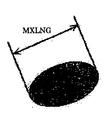
SF−1、SF−2とは、トナーの形状を表すパラメータの一つであり、粉体工学の分野では馴染みのパラメータである。形状係数SF−1とは、図5に示すように、球形物質の形状の丸さの割合を示す値であり、球形物質を2次元平面上に投影して出来る楕円状図形の最大長MXLNGの二乗を図形面積AREAで割って、100π/4を乗じたときの値で表される。
つまり、形状係数SF−1は、次式、
SF−1={(MXLNG)2/AREA}×(100π/4)
で定義されるものである。
(Shape factors SF-1 and SF-2)
SF-1 and SF-2 are parameters representing the shape of the toner, and are familiar parameters in the field of powder engineering. As shown in FIG. 5, the shape factor SF-1 is a value indicating the ratio of the roundness of the shape of the spherical substance, and the maximum length MXLNG of the elliptical figure formed by projecting the spherical substance on a two-dimensional plane. It is expressed by a value obtained by dividing the square by the graphic area AREA and multiplying by 100π / 4.
That is, the shape factor SF-1 is expressed by the following equation:
SF-1 = {(MXLNG) 2 / AREA} × (100π / 4)
Is defined by
このSF−1の値が100の場合には、物質の形状が真球状となり、SF−1の値が大きくなるほど、物質の形状は不定形となる。 When the value of SF-1 is 100, the shape of the substance becomes a true sphere, and as the value of SF-1 increases, the shape of the substance becomes indefinite.
また、形状係数SF−2は、図6に示すように、物質の形状の凹凸の割合を示す数値であり、物質を2次元平面上に投影してできる図形の周長PERIの二乗を図形面積AREAで割って、100/4πを乗じたときの値で表される。 Further, as shown in FIG. 6, the shape factor SF-2 is a numerical value indicating the ratio of the unevenness of the shape of the substance, and the square of the perimeter PERI of the figure formed by projecting the substance on the two-dimensional plane is the figure area. It is expressed as a value when divided by AREA and multiplied by 100 / 4π.
つまり、形状係数SF−2は、次式、
SF−2={(PERI)2/AREA}×(100/4π)で定義されるものである。 SF−2の値が100の場合には、物質の表面に凹凸が存在しないことになり、SF−2の値が大きくなるほど、物質の表面の凹凸は顕著となる。
That is, the shape factor SF-2 is expressed by the following equation:
SF-2 = {(PERI) 2 / AREA} × (100 / 4π). When the value of SF-2 is 100, there is no unevenness on the surface of the substance, and as the value of SF-2 increases, the unevenness on the surface of the substance becomes more prominent.
尚、本発明の実施の形態では、日立製作所製FE−SEM(S−800)を用い、トナー像を100回無作為にサンプリングし、その画像情報は、ニレコ社製画像解析装置(LUSEX3)に導入して解析を行ない、上式より算出したものである。 In the embodiment of the present invention, a toner image is randomly sampled 100 times using an FE-SEM (S-800) manufactured by Hitachi, and the image information is stored in an image analysis apparatus (LUSEX3) manufactured by Nireco. Introduced and analyzed, calculated from the above formula.
トナーの形状が球形に限りなく近づく(SF−1、SF−2ともに100に近づく)と、転写効率が高くなることが本発明者の検討により明らかになった。これは、形状効果によりトナー粒子と該トナー粒子と接触するモノ(トナー粒子同士、像担持体等)との間では点接触しかしないために、トナー流動性が高まったり、像担持体等に対する吸着力(鏡映力)が弱まって、転写電界の影響を受けやすくなるためと考えられる。 It has been clarified by the present inventors that the transfer efficiency increases when the toner shape approaches the spherical shape as much as possible (both SF-1 and SF-2 approach 100). This is because there is only a point contact between the toner particles and the thing (toner particles, image carrier, etc.) in contact with the toner particles due to the shape effect, so that the toner fluidity is increased or the toner is adsorbed on the image carrier, etc. This is thought to be because the force (mirror power) is weakened and is easily affected by the transfer electric field.
一方、トナーの形状が球形に近づくと、メカ的なクリーニング(ブレードクリーニング等)に対して不利に働く。このことは上述したように、トナー流動性が高まったり、像担持体等に対する吸着力(鏡映力)が弱まって、クリーニング部材と像担持体との僅かな間隙を容易にトナーが通過してしまう。よってクリーニング性の面からは、トナーの形状としては、ある程度異形化(SF−1の値が100より大きくなる方向)していたり、ある程度凸凹(SF−2の値が100より大きくなる方向)していた方が好ましい。 On the other hand, when the shape of the toner approaches a spherical shape, it is disadvantageous for mechanical cleaning (such as blade cleaning). As described above, this is because the toner fluidity is increased and the adsorbing force (mirroring force) on the image carrier is weakened so that the toner can easily pass through the slight gap between the cleaning member and the image carrier. End up. Therefore, from the viewpoint of cleaning properties, the shape of the toner is somewhat irregular (in the direction in which the value of SF-1 is greater than 100) or uneven (in the direction in which the value of SF-2 is greater than 100). It is more preferable.
(Dv/Dn(体積平均粒径/個数平均粒径の比))
Dv/Dnとは、トナーの粒度分布を表すパラメータの一つである。該トナーの体積平均粒径(Dv)が4〜8μmであり、個数平均粒径(Dn)との比(Dv/Dn)が1.05〜1.30、好ましくは1.10〜1.25である乾式トナーによると、トナーの粒度分布が狭くなるため、以下のメリットが発生する。
(Dv / Dn (ratio of volume average particle diameter / number average particle diameter))
Dv / Dn is one of the parameters representing the toner particle size distribution. The toner has a volume average particle diameter (Dv) of 4 to 8 μm and a ratio (Dv / Dn) to the number average particle diameter (Dn) of 1.05 to 1.30, preferably 1.10 to 1.25. According to the dry toner, the particle size distribution of the toner becomes narrow, so that the following merits occur.
トナー粒径面での選択現像(画像パターンに応じた(適した)トナー粒径を持つトナー粒子が選択的に現像される)といった現象が発生しにくいため、常時、安定した画像を形成することができる。 A stable image can be formed at all times because a phenomenon such as selective development on the toner particle size surface (toner particles having a (suitable) toner particle size corresponding to the image pattern are selectively developed) hardly occurs. Can do.
トナーリサイクルシステムを塔載している場合、転写されにくい小サイズのトナー粒子が量的に多くリサイクルされることになるが、もともとトナーの粒度分布が狭いため、上述した作用を受けにくく、このことからも常時、安定した画像を形成することができる。二成分現像剤においては、長期にわたるトナーの収支が行われても、現像剤中のトナー粒子径の変動が少なくなり、現像装置における長期の攪拌においても、良好で安定した現像性が得られる。 When a toner recycling system is mounted, a large amount of small-size toner particles that are difficult to transfer are recycled in quantity. However, since the toner particle size distribution is originally narrow, it is difficult to receive the above-mentioned action. Therefore, a stable image can always be formed. In the two-component developer, even if the toner balance for a long time is performed, the fluctuation of the toner particle diameter in the developer is reduced, and good and stable developability can be obtained even in the long-term stirring in the developing device.
一成分現像剤として用いた場合においても、トナーの収支が行われても、トナーの粒子径の変動が少なくなると共に、現像ローラへのトナーのフィルミングや、トナーを薄層化する為のブレード等の部材へのトナーの融着がなく、現像装置の長期の使用(攪拌)においても、良好で安定した現像性及び画像が得られた。 Even when used as a one-component developer, even if the balance of the toner is performed, the fluctuation of the toner particle diameter is reduced, the filming of the toner on the developing roller, and a blade for thinning the toner The toner was not fused to a member such as the above, and good and stable developability and an image were obtained even in the long-term use (stirring) of the developing device.
一般的には、トナーの粒子径は小さければ小さい程、高解像で高画質の画像を得る為に有利であると言われているが、逆に転写性やクリーニング性に対しては不利である。また、本発明の範囲よりも体積平均粒子径が小さい場合、二成分現像剤では現像装置における長期の攪拌においてキャリヤの表面にトナーが融着し、キャリヤの帯電能力を低下させたり、一成分現像剤として用いた場合には、現像ローラへのトナーのフィルミングや、トナーを薄層化する為のブレード等の部材へのトナーの融着を発生させやすくなる。 In general, it is said that the smaller the particle size of the toner, the more advantageous it is to obtain a high-resolution and high-quality image, but it is disadvantageous for transferability and cleaning properties. is there. Also, when the volume average particle diameter is smaller than the range of the present invention, in the case of a two-component developer, the toner is fused to the surface of the carrier during a long period of stirring in the developing device, and the charging ability of the carrier is lowered, or the one-component development is performed. When used as an agent, toner filming on the developing roller and toner fusion to a member such as a blade for thinning the toner are likely to occur.
また、これらの現象は微粉の含有率が本発明の範囲より多いトナーにおいても同様である。 Further, these phenomena are the same for the toner having a fine powder content larger than the range of the present invention.
逆に、トナーの粒子径が本発明の範囲よりも大きい場合には、高解像で高画質の画像を得ることが難しくなると共に、現像剤中のトナーの収支が行われた場合にトナーの粒子径の変動が大きくなる場合が多い。また、体積平均粒子径/個数平均粒子径 が1.30よりも大きい場合も同様であることが明らかとなった。 On the contrary, when the particle diameter of the toner is larger than the range of the present invention, it becomes difficult to obtain a high resolution and high quality image, and when the balance of the toner in the developer is performed, In many cases, the variation of the particle size becomes large. It was also clarified that the same applies when the volume average particle diameter / number average particle diameter is larger than 1.30.
また、体積平均粒子径/個数平均粒子径が1.05より小さい場合には、トナーの挙動の安定化、帯電量の均一化の面から好ましい面もあるが、細線部分を小サイズ粒子で現像、一方、ベタ画像を大サイズ粒子を中心に現像するといったトナー粒径による機能分離ができにくくなるため、かえって好ましくない。 Further, when the volume average particle diameter / number average particle diameter is smaller than 1.05, there is a preferable aspect from the viewpoint of stabilizing the behavior of the toner and uniforming the charge amount, but the thin line portion is developed with small size particles. On the other hand, it is difficult to separate the functions depending on the toner particle diameter, such as developing a solid image mainly on large-size particles, which is not preferable.
(トナー粒径に関わる測定方法)
コールターカウンター法によるトナー粒子の粒度分布の測定装置としては、コールターカウンターTA−IIやコールターマルチサイザーII(いずれもコールター社製)があげられる。以下に測定方法について述べる。
(Measurement method related to toner particle size)
Examples of the measuring device for the particle size distribution of toner particles by the Coulter counter method include Coulter Counter TA-II and Coulter Multisizer II (both manufactured by Coulter). The measurement method is described below.
まず、電解水溶液100〜150ml中に分散剤として界面活性剤(好ましくはアルキルベンゼンスルフォン酸塩)を0.1〜5ml加える。ここで、電解液とは1級塩化ナトリウムを用いて約1%NaCl水溶液を調製したもので、例えばISOTON−II(コールター社製)が使用できる。ここで、更に測定試料を2〜20mg加える。試料を懸濁した電解液は、超音波分散器で約1〜3分間分散処理を行ない、前記測定装置により、アパーチャーとして100μmアパーチャーを用いて、トナー粒子又はトナーの体積、個数を測定して、体積分布と個数分布を算出する。得られた分布から、トナーの体積平均粒径(Dv)、個数平均粒径(Dn)を求めることができる。 First, 0.1 to 5 ml of a surfactant (preferably alkylbenzene sulfonate) is added as a dispersant to 100 to 150 ml of an aqueous electrolytic solution. Here, the electrolytic solution is a solution prepared by preparing a 1% NaCl aqueous solution using primary sodium chloride. For example, ISOTON-II (manufactured by Coulter) can be used. Here, 2 to 20 mg of a measurement sample is further added. The electrolytic solution in which the sample is suspended is subjected to a dispersion treatment with an ultrasonic disperser for about 1 to 3 minutes, and the measurement device is used to measure the volume and number of toner particles or toner using a 100 μm aperture as an aperture. Volume distribution and number distribution are calculated. From the obtained distribution, the volume average particle diameter (Dv) and the number average particle diameter (Dn) of the toner can be obtained.
チャンネルとしては、2.00〜2.52μm未満;2.52〜3.17μm未満;3.17〜4.00μm未満;4.00〜5.04μm未満;5.04〜6.35μm未満;6.35〜8.00μm未満;8.00〜10.08μm未満;10.08〜12.70μm未満;12.70〜16.00μm未満;16.00〜20.20μm未満;20.20〜25.40μm未満;25.40〜32.00μm未満;32.00〜40.30μm未満の13チャンネルを使用し、粒径2.00μm以上乃至40.30μm未満の粒子を対象とする。 As channels, 2.00 to less than 2.52 μm; 2.52 to less than 3.17 μm; 3.17 to less than 4.00 μm; 4.00 to less than 5.04 μm; 5.04 to less than 6.35 μm; 6 Less than 35 to 8.00 μm; less than 8.00 to less than 10.08 μm; less than 10.08 to less than 12.70 μm; less than 12.70 to less than 16.00 μm; less than 16.00 to less than 20.20 μm; Uses 13 channels of less than 40 μm; 25.40 to less than 32.00 μm; 32.00 to less than 40.30 μm, and targets particles having a particle size of 2.00 μm to less than 40.30 μm.
1 感光体(扱うトナーの色で番号の後ろにY、C、M、Kを添える)
2 クリーニング装置
2a クリーニングブレード
2b クリーニングブラシ
2c 廃トナー回収手段
3 帯電手段(スコロトロンチャージャ)
4 露光装置
5 現像装置
5a 現像ローラ
5b 規制ブレード
5c、5d 攪拌手段
5eトナーセンサ
20 第1像担持体ユニット
20a 第1像担持ベルト用クリーニング装置
21 第1像担持ベルト
22 1次転写ローラ
23〜29 第1像担持ベルト支持用ローラ
23 ベルト支持ローラ(クリーニング装置の裏当て)
24 駆動ローラ
26 受像面維持ローラ(2個)
27 テンションローラ
28 転写対向ローラ
29 屈曲ローラ
30 第2像担持体ユニット
30a 第2像担持ベルト用クリーニング装置
31 第2像担持ベルト
32 第2像担持体ユニット用1次転写ローラ
33〜38 第2像担持ベルト支持用ローラ
33 クリーニング裏当てローラ
34 駆動・転写対向ローラ
36 受像面維持ローラ(2個)
37 テンションローラ
40 給紙装置
40a 上部の給紙装置(トレイ)
40b〜40d 給紙カセット
41A〜41D 給紙・分離手段
42A〜42C 搬送ローラ対
43A〜43C 記録体搬送路
44 ジョガー
45 レジストローラ対
46 第1の2次転写手段(2次転写ローラ)
47 第2の2次転写手段(転写チャージャ)
50 記録体移送装手段
50a 搬送ベルト用クリーニング装置
51 搬送ベルト
52〜56 搬送ベルト支持用ローラ
52 受け入れローラ
54 分離・チャージャ対向ローラ
55 クリーニング裏当てローラ
57 吸着用チャージャ
58 除電・分離チャージャ
60 定着装置
70 冷却ローラ対
71 排紙ローラ対
75 排紙スタック部
80 第1画像形成ユニット(うしろに扱う色を示すY,C,M,K添付)
81 第2画像形成ユニット(うしろに扱う色を示すY,C,M,K添付)
84 トナーカートリッジ収納部
85 トナーカートリッジ(うしろに扱う色を示すY,C,M,K添付)
87 廃トナー回収部
90 操作・表示部(ユニット)
95 電装・制御装置
100 画像形成装置
200 画像読取装置
300 追加設置が可能の給紙装置
A1、A2 矢印
F ファン
Y イエロー
C シアン
M マゼンタ
K ブラック
Q 除電装置
y 軸(鉛直方向の座標軸)
α 第1、第2像担持ベルト受像面のなす角度
1 Photoconductor (Y, C, M, K after the number in the color of the toner to be handled)
2
4
24 Drive roller 26 Image-receiving surface maintaining roller (2 pieces)
27 Tension roller 28 Transfer counter roller 29
33 Cleaning backing roller 34 Drive /
37
40b to 40d
47 Second secondary transfer means (transfer charger)
50 Recording medium transporting means 50a Conveyor belt cleaning device 51
81 Second image forming unit (attached Y, C, M, K indicating the color to be handled behind)
84
87 Waste
95 Electrical Equipment /
α Angle formed by the image receiving surfaces of the first and second image bearing belts
Claims (17)
第2画像形成ユニットで形成される第2画像を第2像担持ベルトに担持させることが可能な第2像担持ユニットと、
前記第1像担持ユニットが担持する前記第1画像を記録体の第1の面に転写させるための第1転写手段を含む第1転写ステーションと、
前記第2像担持ユニットが担持する前記第2画像を記録体の第2の面に転写させるための第2転写手段を含む第2転写ステーションと、
前記第1、第2転写ステーションの間に記録体を供給、搬送させる手段を含む記録体搬送路と、
前記第1、第2転写ステーションの間を出た記録体を加熱定着装置まで搬送する、無端ベルト状に構成された搬送手段と、
前記搬送手段の外側に、クリーニング装置、前記記録体を吸着させるための吸着用チャージャ及び除電・分離チャージャと、
両面の画像を定着させる加熱定着装置とを備え、
前記吸着用チャージャは、搬送手段の表面を、前記第1画像及び前記第2画像を形成する現像剤の極性と同じ極性で帯電させるものであり、
前記第2像担持ユニットの速度は前記第1像担持ユニット速度の出力により決定し、前記搬送手段は前記第2像担持ユニットの速度を検出し速度を決定し、前記加熱定着装置は前記搬送手段の速度を検出して速度を決定することにより、記録体の搬送速度を常に一定に制御する
ことを特徴とする画像形成装置。 A first image carrying unit capable of carrying a first image formed by the first image forming unit on a first image carrying belt;
A second image carrying unit capable of carrying a second image formed by the second image forming unit on a second image carrying belt;
A first transfer station including first transfer means for transferring the first image carried by the first image carrying unit to a first surface of a recording medium;
A second transfer station including second transfer means for transferring the second image carried by the second image carrying unit to the second surface of the recording medium;
A recording medium conveyance path including means for supplying and conveying the recording medium between the first and second transfer stations;
A conveying means configured in an endless belt shape for conveying the recording medium exiting between the first and second transfer stations to a heat fixing device;
A cleaning device, an adsorption charger for adsorbing the recording medium, and a charge eliminating / separating charger outside the conveying means,
A heat fixing device for fixing images on both sides,
The adsorption charger is for charging the surface of the conveying means with the same polarity as the polarity of the developer forming the first image and the second image,
The speed of the second image carrying unit is determined by the output of the first image carrying unit speed, the conveying means detects the speed of the second image carrying unit and determines the speed, and the heating and fixing device is the conveying means. An image forming apparatus characterized in that the conveyance speed of a recording medium is always controlled to be constant by detecting the speed of the recording medium and determining the speed .
Priority Applications (1)
| Application Number | Priority Date | Filing Date | Title |
|---|---|---|---|
| JP2005040770A JP4800636B2 (en) | 2005-02-17 | 2005-02-17 | Image forming apparatus |
Applications Claiming Priority (1)
| Application Number | Priority Date | Filing Date | Title |
|---|---|---|---|
| JP2005040770A JP4800636B2 (en) | 2005-02-17 | 2005-02-17 | Image forming apparatus |
Publications (2)
| Publication Number | Publication Date |
|---|---|
| JP2006227289A JP2006227289A (en) | 2006-08-31 |
| JP4800636B2 true JP4800636B2 (en) | 2011-10-26 |
Family
ID=36988711
Family Applications (1)
| Application Number | Title | Priority Date | Filing Date |
|---|---|---|---|
| JP2005040770A Expired - Fee Related JP4800636B2 (en) | 2005-02-17 | 2005-02-17 | Image forming apparatus |
Country Status (1)
| Country | Link |
|---|---|
| JP (1) | JP4800636B2 (en) |
Families Citing this family (4)
| Publication number | Priority date | Publication date | Assignee | Title |
|---|---|---|---|---|
| JP2008116651A (en) * | 2006-11-02 | 2008-05-22 | Ricoh Co Ltd | Developing device and image forming apparatus |
| JP4921129B2 (en) * | 2006-11-22 | 2012-04-25 | 株式会社リコー | Cleaning unit, belt unit, image forming device |
| JP2010060705A (en) * | 2008-09-02 | 2010-03-18 | Ricoh Co Ltd | Image forming apparatus |
| JP5824948B2 (en) * | 2011-08-04 | 2015-12-02 | 株式会社リコー | Fixing apparatus and image forming apparatus |
Family Cites Families (27)
| Publication number | Priority date | Publication date | Assignee | Title |
|---|---|---|---|---|
| US4427285A (en) * | 1981-02-27 | 1984-01-24 | Xerox Corporation | Direct duplex printing on pre-cut copy sheets |
| JPH07209926A (en) * | 1994-01-25 | 1995-08-11 | Konica Corp | Both-side color image forming device |
| JPH08305105A (en) * | 1995-05-02 | 1996-11-22 | Ricoh Co Ltd | Image forming device |
| JP3221339B2 (en) * | 1996-12-09 | 2001-10-22 | キヤノン株式会社 | Image forming device |
| JP3484996B2 (en) * | 1998-11-06 | 2004-01-06 | 富士ゼロックス株式会社 | Double-sided printing device |
| JP4143256B2 (en) * | 2000-11-30 | 2008-09-03 | 株式会社リコー | Image forming apparatus |
| JP2002351168A (en) * | 2001-05-22 | 2002-12-04 | Konica Corp | Image forming apparatus |
| JP4500511B2 (en) * | 2002-07-03 | 2010-07-14 | キヤノン株式会社 | Image forming apparatus |
| JP4193933B2 (en) * | 2002-07-29 | 2008-12-10 | 株式会社リコー | Image forming apparatus |
| JP2004338894A (en) * | 2003-05-16 | 2004-12-02 | Fuji Xerox Co Ltd | Image forming device and speed measuring device |
| JP2005017558A (en) * | 2003-06-25 | 2005-01-20 | Ricoh Co Ltd | Image forming apparatus and image forming method |
| JP4351486B2 (en) * | 2003-07-07 | 2009-10-28 | 株式会社リコー | Image forming apparatus |
| JP4452041B2 (en) * | 2003-07-11 | 2010-04-21 | 株式会社東芝 | Image forming apparatus |
| JP4451205B2 (en) * | 2003-09-01 | 2010-04-14 | 株式会社リコー | Double-sided transfer method, double-sided transfer device, image forming method, image forming apparatus, and image forming system |
| JP4340524B2 (en) * | 2003-12-11 | 2009-10-07 | 株式会社リコー | Image forming apparatus |
| JP2005189607A (en) * | 2003-12-26 | 2005-07-14 | Ricoh Co Ltd | Image forming apparatus |
| JP2005239387A (en) * | 2004-02-27 | 2005-09-08 | Ricoh Co Ltd | Recording medium carrying device, and image forming device |
| JP2005242169A (en) * | 2004-02-27 | 2005-09-08 | Ricoh Co Ltd | Image forming apparatus |
| JP2005350180A (en) * | 2004-06-09 | 2005-12-22 | Ricoh Co Ltd | Image forming apparatus |
| JP4719515B2 (en) * | 2004-06-14 | 2011-07-06 | 株式会社リコー | Image forming apparatus |
| JP4610939B2 (en) * | 2004-06-14 | 2011-01-12 | 株式会社リコー | Image forming apparatus |
| JP4474210B2 (en) * | 2004-06-14 | 2010-06-02 | 株式会社リコー | Image forming apparatus |
| JP2005352401A (en) * | 2004-06-14 | 2005-12-22 | Ricoh Co Ltd | Image forming apparatus |
| JP2006001686A (en) * | 2004-06-16 | 2006-01-05 | Ricoh Co Ltd | Recording material carrying device and image forming device |
| JP4358049B2 (en) * | 2004-06-30 | 2009-11-04 | 株式会社リコー | Image forming apparatus |
| JP2006085016A (en) * | 2004-09-17 | 2006-03-30 | Ricoh Co Ltd | Image forming apparatus |
| JP2006085015A (en) * | 2004-09-17 | 2006-03-30 | Ricoh Co Ltd | Image forming apparatus |
-
2005
- 2005-02-17 JP JP2005040770A patent/JP4800636B2/en not_active Expired - Fee Related
Also Published As
| Publication number | Publication date |
|---|---|
| JP2006227289A (en) | 2006-08-31 |
Similar Documents
| Publication | Publication Date | Title |
|---|---|---|
| JP4681972B2 (en) | Developing device and image forming apparatus | |
| JP4800636B2 (en) | Image forming apparatus | |
| JP2006330199A (en) | Image forming apparatus, toner and carrier | |
| JP2006251246A (en) | Image forming apparatus | |
| JP4810232B2 (en) | Image forming apparatus | |
| JP2006251371A (en) | Image forming apparatus | |
| JP2010210915A (en) | Image forming apparatus | |
| JP2006227292A (en) | Image forming apparatus | |
| JP2006001686A (en) | Recording material carrying device and image forming device | |
| JP2006315787A (en) | Recording material conveying device and image forming device | |
| JP4855731B2 (en) | Image forming apparatus and cleaning method thereof | |
| JP2005352401A (en) | Image forming apparatus | |
| JP2007226165A (en) | Conveying device, image forming apparatus and toner | |
| JP4953188B2 (en) | Cleaning method and image forming apparatus | |
| JP4225867B2 (en) | Image forming apparatus | |
| JP2007003733A (en) | Image forming apparatus | |
| JP2005017558A (en) | Image forming apparatus and image forming method | |
| JP4358049B2 (en) | Image forming apparatus | |
| JP4340524B2 (en) | Image forming apparatus | |
| JP4877723B2 (en) | Image forming apparatus | |
| JP2007047587A (en) | Method and device for cleaning, and image forming apparatus | |
| JP2006285172A (en) | Image forming apparatus | |
| JP4496071B2 (en) | Recording paper transport device and image forming apparatus | |
| JP2010210914A (en) | Image forming apparatus | |
| JP2007010920A (en) | Image forming apparatus |
Legal Events
| Date | Code | Title | Description |
|---|---|---|---|
| A621 | Written request for application examination |
Free format text: JAPANESE INTERMEDIATE CODE: A621 Effective date: 20080122 |
|
| RD02 | Notification of acceptance of power of attorney |
Free format text: JAPANESE INTERMEDIATE CODE: A7422 Effective date: 20080130 |
|
| A977 | Report on retrieval |
Free format text: JAPANESE INTERMEDIATE CODE: A971007 Effective date: 20100701 |
|
| A131 | Notification of reasons for refusal |
Free format text: JAPANESE INTERMEDIATE CODE: A131 Effective date: 20101207 |
|
| A521 | Written amendment |
Free format text: JAPANESE INTERMEDIATE CODE: A523 Effective date: 20110125 |
|
| A131 | Notification of reasons for refusal |
Free format text: JAPANESE INTERMEDIATE CODE: A131 Effective date: 20110517 |
|
| A521 | Written amendment |
Free format text: JAPANESE INTERMEDIATE CODE: A523 Effective date: 20110711 |
|
| TRDD | Decision of grant or rejection written | ||
| A01 | Written decision to grant a patent or to grant a registration (utility model) |
Free format text: JAPANESE INTERMEDIATE CODE: A01 Effective date: 20110802 |
|
| A01 | Written decision to grant a patent or to grant a registration (utility model) |
Free format text: JAPANESE INTERMEDIATE CODE: A01 |
|
| A61 | First payment of annual fees (during grant procedure) |
Free format text: JAPANESE INTERMEDIATE CODE: A61 Effective date: 20110804 |
|
| FPAY | Renewal fee payment (event date is renewal date of database) |
Free format text: PAYMENT UNTIL: 20140812 Year of fee payment: 3 |
|
| R150 | Certificate of patent or registration of utility model |
Free format text: JAPANESE INTERMEDIATE CODE: R150 |
|
| LAPS | Cancellation because of no payment of annual fees |