JP4496071B2 - Recording paper transport device and image forming apparatus - Google Patents
Recording paper transport device and image forming apparatus Download PDFInfo
- Publication number
- JP4496071B2 JP4496071B2 JP2004378903A JP2004378903A JP4496071B2 JP 4496071 B2 JP4496071 B2 JP 4496071B2 JP 2004378903 A JP2004378903 A JP 2004378903A JP 2004378903 A JP2004378903 A JP 2004378903A JP 4496071 B2 JP4496071 B2 JP 4496071B2
- Authority
- JP
- Japan
- Prior art keywords
- recording paper
- belt
- charge
- roller
- recording
- Prior art date
- Legal status (The legal status is an assumption and is not a legal conclusion. Google has not performed a legal analysis and makes no representation as to the accuracy of the status listed.)
- Expired - Fee Related
Links
Images


Description
本発明は、複写機、プリンタ、ファクシミリ等の画像形成装置、及びにこれに用いられる記録紙搬送装置に関するものである。より詳しくは、転写紙等の記録紙の両面に可視像を転写し、両面の可視像を同時に定着する方式の画像形成装置、及びにこれに用いられる記録紙搬送装置に関するものである。 The present invention relates to an image forming apparatus such as a copying machine, a printer, a facsimile, and the like, and a recording paper conveying apparatus used therefor. More particularly, the present invention relates to an image forming apparatus that transfers a visible image onto both sides of a recording sheet such as a transfer sheet and fixes the visible images on both sides at the same time, and a recording sheet conveying apparatus used therefor.
従来、両面に未定着のトナー像を担持した記録紙を、定着装置まで搬送する搬送手段として、例えば、特許文献1に記載されいる記録紙搬送手段が知られている。 2. Description of the Related Art Conventionally, for example, a recording paper conveying unit described in Patent Document 1 is known as a conveying unit that conveys a recording paper carrying an unfixed toner image on both sides to a fixing device.
特許文献1に記載されいる記録紙搬送手段は、記録紙搬送の際に、非接触型の電荷発生装置(以下、電荷チャージャと呼ぶ)により記録紙にトナーの帯電極性と逆極性の電荷を放電付与することにより、記録紙とトナーとの静電的付着力を強くしている。さらに、搬送ベルトにトナー像と同極性の電荷を付与して、記録紙と搬送ベルトとの密着性を高めるとともに、記録紙のトナー像が搬送ベルトに静電的に付着することを防止している。 The recording paper conveying means described in Patent Document 1 discharges a charge having a polarity opposite to that of the toner to the recording paper by a non-contact type charge generation device (hereinafter referred to as a charge charger) when conveying the recording paper. By imparting, the electrostatic adhesion between the recording paper and the toner is strengthened. Furthermore, by applying a charge of the same polarity as the toner image to the conveyance belt, the adhesion between the recording paper and the conveyance belt is improved, and the toner image on the recording paper is prevented from electrostatically adhering to the conveyance belt. Yes.
しかしながら、特許文献1に記載されている記録紙搬送手段は、記録紙が搬送ベルトから分離する分離部において、記録紙のコシによる分離力よりも記録紙と搬送ベルトとの静電的な吸着力の方が強くなって、記録紙が搬送ベルトから分離できず、用紙ジャムが発生する不具合がある。特に、厚さの薄い記録紙は、搬送ベルトから分離できず、用紙ジャムが発生する不具合が顕著に現れてしまう。これは、厚さの薄い記録紙は、コシが弱いため搬送ベルトから分離する分離力が弱く、また抵抗値が低いため帯電し易く搬送ベルトとの静電的な吸着力が強いためである。 However, the recording paper conveying means described in Japanese Patent Laid-Open No. 2004-228561 has an electrostatic adsorption force between the recording paper and the conveyance belt rather than the separation force due to the stiffness of the recording paper in the separation unit where the recording paper is separated from the conveyance belt. However, there is a problem that the recording paper cannot be separated from the conveying belt and paper jam occurs. In particular, a thin recording paper cannot be separated from the conveying belt, and a problem that a paper jam occurs appears remarkably. This is because the recording paper with a small thickness is weak and has a weak separation force to separate from the conveyance belt, and since the resistance value is low, it is easily charged and has a strong electrostatic adsorption force with the conveyance belt.
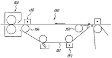
そこで、例えば、図6に示すように、搬送ベルト151の外側に除電手段としての除電チャージャ158を設けて、搬送ベルト151に担持された記録紙を介して搬送ベルト151の電荷を除電チャージャ158で除去している。具体的には、除電チャージャ158からトナー像の電荷と逆極性の電荷を、記録紙を介して搬送ベルト151のおもて面に付与して、トナー像の電荷と同極性に帯電した搬送ベルト151の除電を行う。これにより、記録紙と搬送ベルト151との静電的な吸着力を記録紙が搬送ベルト151から分離する分離力よりも弱めて、記録紙が搬送ベルト151から分離することができる。
Therefore, for example, as shown in FIG. 6, a
しかしながら、除電チャージャ158の放電により、記録紙上のトナーが飛散してトナー像を乱すおそれがある。さらに、飛散したトナーが除電チャージャ158に付着し除電チャージャ158の性能が劣化して搬送ベルト151の除電を良好に行うことができない場合があった。そこで、例えば、除電手段を除電ローラとし搬送ベルトのおもて面に直接接触させてニップを形成する。そして、このニップに記録紙が通過する際、除電ローラから記録紙を介して搬送ベルト151にトナー像の電荷と逆極性の電荷を付与してトナー像の電荷と同極性に帯電した搬送ベルトの除電を行うことも考えられる。しかしながら、記録紙上のトナーが除電ローラに付着して、記録紙上のトナー像が乱れるという問題がある。
However, due to the discharge of the
本発明は、上記問題に鑑みなされたものであり、その目的とするところは、記録紙上のトナー像を乱すことなく、搬送ベルトを除電することができる記録紙搬送装置及び画像形成装置を提供することである。 The present invention has been made in view of the above problems, and an object of the present invention is to provide a recording paper conveyance device and an image forming apparatus that can neutralize the conveyance belt without disturbing the toner image on the recording paper. That is.
上記目的を達成するために、請求項1の発明は、2つ以上のローラ状の支持部材に張架され、可視像を担持する像担持体から転写手段によって可視像が転写され表面に該可視像の電荷とは逆極性の電荷を帯びたシート状の記録紙を、該可視像を該記録紙に定着する定着手段に搬送する記録紙搬送ベルトと、該記録紙搬送ベルトに該記録紙の表面が帯びている電荷とは逆極性の電荷を付与する電荷付与手段とを有する記録紙搬送装置において、該記録紙が該記録紙搬送ベルトから分離する前に、記録紙搬送ベルトの裏面から記録紙の表面が帯びている電荷と同極性の電荷を該記録紙搬送ベルトに付与して、該記録紙搬送ベルトの帯びている電荷を除去する除電手段を備え、2つ以上の上記支持部材のうち、上記記録紙搬送ベルトの記録紙搬送方向の最下流側である上記記録紙と上記記録紙搬送ベルトとの分離部で、上記記録紙搬送ベルトを内側から支持し該分離部を構成する支持部材を分離部支持部材とし、上記除電手段から上記記録紙搬送ベルトに加える電荷が、上記分離支持部材にリークしない位置に上記除電手段を配置したことを特徴とするものである。
また、請求項2の発明は、請求項1の記録紙搬送装置において、上記記録紙搬送ベルトが担持する記録紙には、両面に可視像が転写されていることを特徴とするものである。
また、請求項3の発明は、請求項1または2の記録紙搬送装置において、上記記録紙搬送ベルトの体積抵抗値が106[Ωcm]以上1010[Ωcm]以下であることを特徴とするものである。
また、請求項4の発明は、請求項1乃至3いずれかの記録紙搬送装置において、上記記録紙搬送ベルトの記録紙搬送方向の最上流側である該記録紙が該記録紙搬送ベルトへ受渡される受渡し部で、該記録紙搬送ベルトを内側から支持し該受渡し部を構成する支持部材を受渡し部支持部材とし、該分離部支持部材の半径をrとしたとき該分離部支持部材の中心から記録紙搬送方向上流側へ1.5r以上離れた位置から、該分離部支持部材と受渡し部支持部材との中間点までの間に上記除電手段を配置することを特徴とするものである。
また、請求項5の発明は、請求項1乃至4いずれかの記録紙搬送装置において、上記除電手段は、上記記録紙搬送ベルトの裏面に接触して電荷を付与することを特徴とするものである。
また、請求項6の発明は、請求項1乃至5いずれかの記録紙搬送装置において、上記記録紙搬送ベルトが担持する記録紙の特性に基づいて、上記除電手段から上記記録紙搬送ベルトに付与する電荷量を制御することを特徴とするものである。
また、請求項7の発明は、請求項1乃至6いずれかの記録紙搬送装置において、上記記録紙が上記除電手段に到達する前に該除電手段へバイアスの印加を開始し、該記録紙が該除電手段を通過しおえた後に該除電手段へバイアスの印加を停止することを特徴とするものである。
また、請求項8の発明は、請求項1乃至7いずれかの記録紙搬送装置において、上記除電手段にバイアスを印加する電源装置を備え該電源装置は、定電流電源であることを特徴とするものである。
また、請求項9の発明は、可視像を担持する像担持体と、該像担持体に可視像を形成する可視像形成手段と、記録紙を保持する記録紙保持部材を所定方向に移動させながら、該像担持体上の可視像を該記録紙保持部材上の記録紙に転写せしめる転写手段と、該転写手段を経由した後の記録紙を受け入れてその可視像を該記録紙に定着せしめる定着手段とを有する画像形成装置において、該転写手段から該定着手段まで記録紙を搬送する記録紙搬送手段として、請求項1乃至8いずれかの記録紙搬送装置を用いたことを特徴とするものである。
To achieve the above object, the invention of claim 1 is stretched in two or more roller-shaped support member, the visible image is transferred by the transfer means from the image bearing member that Soo responsible for variable visual images A recording paper transport belt for transporting a sheet-like recording paper having a charge opposite in polarity to the charge of the visible image on a surface thereof to a fixing means for fixing the visible image to the recording paper; and the recording paper transport in the charge the surface of the recording sheet is charged to the belt recording sheet conveying device having a charge applying means for applying a reverse polarity charge, before the recording sheet is separated from the recording sheet conveying belt, the recording sheet the back surface of the recording paper surface charged electrical charge of the same polarity as the charge of the conveying belt by applying to the conveyor belt the recording paper, comprising a charge removing means for removing electric charges charged in the recording paper conveying belt, two Among the above support members, the recording paper conveyance of the recording paper conveyance belt A separation portion between the recording paper and the recording paper conveyance belt, which is the most downstream side in the direction, supporting the recording paper conveyance belt from the inside, and a support member constituting the separation portion as a separation portion support member; The charge removing means is disposed at a position where the charge applied to the recording paper transport belt does not leak to the separation support member .
According to a second aspect of the present invention, in the recording paper conveying apparatus according to the first aspect, a visible image is transferred on both sides of the recording paper carried by the recording paper conveying belt. .
According to a third aspect of the present invention, in the recording paper conveyance device according to the first or second aspect , the volume resistance value of the recording paper conveyance belt is 10 6 [Ωcm] or more and 10 10 [Ωcm] or less. Is.
The invention of claim 4, in any of the recording sheet conveying apparatus according to claim 1 to 3, the recording paper is the most upstream side of the recording paper conveying direction of the recording sheet conveyance belt to the recording sheet conveying belt In the delivery part to be delivered, the support member constituting the delivery part that supports the recording paper transport belt from the inside is a delivery part support member, and when the radius of the separation part support member is r, the separation part support member The neutralizing means is arranged between a position 1.5r or more away from the center upstream of the recording paper conveyance direction and an intermediate point between the separation unit support member and the delivery unit support member. .
According to a fifth aspect of the present invention, in the recording paper conveyance device according to any one of the first to fourth aspects, the charge eliminating means applies a charge by contacting the back surface of the recording paper conveyance belt. is there.
The invention of claim 6 is applied in any of the recording paper conveying apparatus according to claim 1 to 5, the recording paper conveying belt based on the characteristics of the recording paper carrying, in the recording sheet conveying belt from said discharging means The amount of charge to be controlled is controlled.
According to a seventh aspect of the present invention, in the recording paper conveyance device according to any one of the first to sixth aspects , before the recording paper reaches the static eliminator, application of a bias to the static eliminator is started. After passing through the static eliminator, the application of a bias to the static eliminator is stopped.
According to an eighth aspect of the present invention, in the recording paper conveying apparatus according to any one of the first to seventh aspects , a power supply device for applying a bias to the neutralizing means is provided, and the power supply device is a constant current power supply. Is.
According to a ninth aspect of the present invention, an image carrier that carries a visible image, a visible image forming unit that forms a visible image on the image carrier, and a recording paper holding member that holds the recording paper are arranged in a predetermined direction. A transfer means for transferring the visible image on the image carrier onto the recording paper on the recording paper holding member, and receiving the recording paper after passing through the transfer means. in the image forming apparatus having a fixing unit that allowed to fix to the recording paper that, as the recording sheet conveying means for conveying the recording paper from the transfer means to the fixing means, with either of the recording sheet conveying apparatus according to claim 1 to 8 It is characterized by.
本発明によれば、除電手段は、記録紙搬送部材の裏面から記録紙が帯びている電荷と同極性の電荷を付与して、記録紙搬送部材の帯びている電荷を除去する。これにより、記録紙搬送部材のおもて面から記録紙搬送部材の電荷を除去するものに比べて、記録紙上の未定着の可視像が乱れることを抑制することができる。 According to the present invention, the charge eliminating unit applies a charge having the same polarity as the charge on the recording paper from the back surface of the recording paper transport member to remove the charge on the recording paper transport member. Thereby, it is possible to suppress the unfixed visible image on the recording paper from being disturbed as compared with the case where the charge of the recording paper conveying member is removed from the front surface of the recording paper conveying member.
以下、本発明を画像形成装置に適用した実施形態について説明する。図1は、実施形態1にかかる画像形成装置100としての電子写真方式で両面プリント可能なフルカラープリンタを示す。
図1に示す画像形成装置本体100の内部において、記録紙搬送路43Aを境にして、上部には第1画像ユニット20を配置し、下部には第2画像ユニット30を配置している。第1画像ユニット20は矢印方向に無端移動する第1トナー像搬送ベルトである第1中間転写ベルト21を備え、第2画像ユニット30は矢印方向に無端移動する第2トナー像搬送ベルトである第2中間転写ベルト31を備えている。第1中間転写ベルト21の上部張架面には、4個の第1トナー像形成手段である第1画像形成ユニット80Y、80C、80M、80Kが配置されている。一方、第2中間転写ベルト31の上部張架面には、4個の第2トナー像形成手段である第2画像形成ユニット81Y、81C、81M、81Kが配置されている。これら第1、第2画像形成ユニットの番号に沿えたY、C、M、Kは、扱うトナーの色と対応させているもので、Yはイエロー、Cはシアン、Mはマゼンタ、Kはブラックを意味している。第1、第2画像形成ユニットに備えられ、第1中間転写ベルト21と第2中間転写ベルト31とともに回転する感光体1に対しても同じようにY、C、M、Kを沿えている。なお感光体1Yから1Kは各画像形成ユニット内では同間隔に配置され、少なくとも画像形成時にはそれぞれ中間転写ベルト21、31との張架部の一部と接触する。この接触する面をそれぞれ第1受像面F1、第2受像面F2と呼び、互いの位置関係を図2に示す。
Embodiments in which the present invention is applied to an image forming apparatus will be described below. FIG. 1 illustrates a full-color printer capable of duplex printing by an electrophotographic method as the
In the image forming apparatus
図2に示すように、第1受像面F1と第2受像面F2とが形成する角のうち、第1、第2画像形成ユニットを含む角の角度をαとした時、αの値が180°より大きく、270°以下となるようにする。
さらに、上部にある第1中間転写ベルト21の水平投影面と、下部にある第2中間転写ベルトの水平投影面との少なくとも一部が、重なるような構成を採用している。つまり下部にある第2中間転写ベルトが、上部にある第1中間転写ベルトの下方にもぐりこむような形状である。このような構成を採用することにより、横方向についてよりコンパクトなレイアウトが可能となる。
As shown in FIG. 2, when the angle of the angle including the first and second image forming units among the angles formed by the first image receiving surface F1 and the second image receiving surface F2 is α, the value of α is 180. It should be larger than 270 ° and smaller than 270 °.
Further, a configuration is adopted in which at least a part of the horizontal projection surface of the first
扱うトナーの色は異なるが、第1画像形成ユニット80Y、80C、80M、80Kの構成はそれぞれ同じであるので、第1画像形成ユニット80としてその構成を図3により説明する。
図3において、画像形成装置100の動作時に、不図示の駆動源により、矢印方向に回転するよう回転可能に支持された円筒状の感光体1が配設されている。そして、感光体1の周囲に、静電写真プロセスに従い帯電手段であるスコロトロンチャージャ3、露光装置4、現像装置5、クリーニング装置2、光除電装置Q等の作像部材や電位センサS1、画像センサS2が配設されている。
感光体1は、例えば直径30〜120mm 程度のアルミニウム円筒表面に光導電性物質である有機感光層(OPC)を形成したものである。アモルファスシリコン(a−Si)層を形成した感光体も採用可能である。またベルト状の感光体も採用できる。クリーニング装置2は、クリーニングブラシ2a、クリーニングブレード2b、回収部材2cを備え、感光体表面に残留するトナー等の異物を除去、回収する。
Although the toner colors to be handled are different, the configurations of the first image forming units 80Y, 80C, 80M, and 80K are the same. Therefore, the configuration of the first
In FIG. 3, when the
The photoreceptor 1 is obtained by forming an organic photosensitive layer (OPC), which is a photoconductive substance, on an aluminum cylinder surface having a diameter of about 30 to 120 mm. A photoconductor on which an amorphous silicon (a-Si) layer is formed can also be used. A belt-like photoreceptor can also be employed. The
露光装置4は、各色毎の画像データ対応の光を、帯電手段で一様に帯電済みの各感光体1の表面に走査し、静電潜像を形成する。図示例の露光装置4は、発光素子としてLED(発光ダイオード)アレイと結像素子からなる露光装置であるが、レーザ光源、ポリゴンミラー等を用い、形成すべき画像データに応じて変調したビーム光によるレーザスキャン方式の露光装置も採用できる。また、帯電手段として、チャージャ3のほかに、感光体1の表面に接触させるタイプ、たとえば帯電ローラも採用できる。
The exposure device 4 scans the light corresponding to the image data for each color on the surface of each photoreceptor 1 that has been uniformly charged by the charging means, and forms an electrostatic latent image. The exposure apparatus 4 in the illustrated example is an exposure apparatus that includes an LED (light emitting diode) array and an imaging element as light emitting elements, but uses a laser light source, a polygon mirror, etc., and beam light modulated according to image data to be formed. It is also possible to adopt a laser scanning type exposure apparatus. In addition to the
このときの現像は、トナーとキャリヤからなる二成分現像剤を採用している現像方式である。負荷電の感光体1に対し露光装置4により各感光体1の表面に形成された色毎の静電潜像は、感光体の帯電極性と同極性(マイナス極性)の所定の色のトナーで現像され、顕像となる。いわゆる反転現像がおこなわれる。
イエロー(Y)、シアン(C)、マゼンタ(M)、ブラック(K)の各色トナーは、各色を扱う現像装置で消費されると、透磁式のトナー検知手段5eにより検知される。そして、画像形成装置100内部のトナーカートリッジ収納部85に備えるトナーカートリッジ86から、不図示の供給手段により、各色のトナーを各現像装置5に供給される。
この供給手段として、公知のモーノポンプを用いる方式のものが採用できる。この方式によればトナーカートリッジの設置場所の制約が少ないため、画像形成装置内部のスペース配分に対し有利である。またトナーが適時補給できるため、現像装置に大きなトナー貯留スペースを設けなくてすみ、現像装置の小型化がはかれる。
The development at this time is a development system that employs a two-component developer composed of toner and carrier. The electrostatic latent image for each color formed on the surface of each photoconductor 1 by the exposure device 4 with respect to the negatively charged photoconductor 1 is a toner of a predetermined color having the same polarity (negative polarity) as the charged polarity of the photoconductor. Developed to become a visible image. So-called reversal development is performed.
The yellow (Y), cyan (C), magenta (M), and black (K) toners are detected by the magnetically permeable
As this supply means, a system using a known MONO pump can be adopted. According to this method, there are few restrictions on the installation location of the toner cartridge, which is advantageous for space allocation in the image forming apparatus. Further, since the toner can be replenished in a timely manner, it is not necessary to provide a large toner storage space in the developing device, and the developing device can be downsized.
現像装置5には、トナーとキャリヤの攪拌、搬送用のスクリュー5cや5dが備えてある。現像装置5が画像形成装置100に装着されているとき、トナー補給手段の一端が、スクリュー5dの一部に接続されている。スクリュー5cによりトナーは、矢印方向に回転する現像ローラ5aに供給されるが、ブレード5bにより、現像ローラ5a表面のトナー層の厚みは、所定の厚みになるよう規制される。現像ローラ5aは、ステンレスやアルミニュウム製の円筒で、回転可能にかつ感光体との距離が正規に確保されるように現像装置5のフレームに支持され、内部には所定の磁力線が構成されるようにマグネットが備えてある。なおトナーは従来から公知の方法で得られる球形や不定形のトナーが用いられる。体積平均粒径が20μm以下、好ましくは10μm以下4μm以上の粒子からなるものである。またキャリヤも従来公知の方法で得られるものが用いられる。キャリヤの粒径として、体積平均粒径が25μmから60μm程度である。
The developing device 5 is provided with
第2画像ユニット30に使われる第2の画像形成ユニット81Y、M、C、Kの構成はそれぞれ同じなので、第2の画像形成ユニット81として、図4により説明する。
図4に示した第2の画像形成ユニット81は、第1の画像形成ユニット80と構成部材が同じであるが、図3のものと比べ感光体1の回転方向が異なっている。しかし互いに、図中の矢印で示す感光体1の回転軸1aを通るy軸に対し対象の形をしている。この形状は、感光体1の周囲に配備する画像形成用部材の配置にも関係するが、重要な事項である。つまり画像形成装置100との結合部、たとえば駆動手段との結合部、電気的接続部、トナー供給部、トナー排出部の結合方法を配慮している。これにより、第1の画像形成ユニット80Y、M、C、Kと、第2の画像形成ユニット81Y、M、C、Kとに互換性をもたせることができる。従って第1の画像形成ユニットと第2の画像形成ユニット用に個別に現像装置、クリーニング装置、部品を製造する必要がなく、部品製造、部品の管理上での効率が高く、全体のコスト低減がはかれる。
第1と第2の画像形成ユニットをy軸中心にした軸対象の形で、第1の画像ユニット20と第2の画像ユニット30で使用できる以下の二つの条件がある。第1条件として、感光体1の周囲で画像形成のための部材を配備していない周面が確保されていること、つまり中間転写ベルトが当接可能な範囲が広く確保されていること。そして第2条件として、第1の中間転写ベルト21の受像面F1と第2の中間転写ベルト31受像面F2の配置角度が適切であることがあげられる。
Since the second image forming units 81Y, 81M, 81C, and 81K used in the
The second
There are the following two conditions that can be used in the
第1条件、第2条件について図3、図4により説明する。図3あるいは図4において、中間転写ベルト21あるいは31は、矢印A1とA2の間に設置可能である。つまりA1側は現像装置5で、A2側はクリーニング装置2にベルトが接触しない範囲に中間転写ベルトが設置できることを示している。図3に第2の像担持ベルト31を含めているのは、感光体1の回転軸1aを含むy軸に対し対象の画像形成ユニットが配置できる中間転写ベルトを示している。
もし、画像形成ユニット80をy軸に直交する軸を対象に上下反転して画像形成ユニット81として使うとすると、地球重力の影響により少なくとも現像装置5において、トナーの攪拌、現像ローラ5aへのトナー補給等の条件は異なる。これにより、画像形成ユニット80の部材をそれぞれ最適化しなければならず、部品の共通化も不可能となる。
The first condition and the second condition will be described with reference to FIGS. 3 or 4, the
If the
図2に示すように、第1像担持ベルト21の受像面に対し第2像担持ベルト31の受像面との位置関係として角度αを180度より大きく270度以下としている。好ましくは210度から255度としたとき、画像形成ユニットとして、第1像担持ベルトには図3に示す形態、第2像担持ベルトには図4に示す形態のものが採用できる。つまり上述のごとく部品の共通化を不可能にしてしまう画像形成ユニットとなることが回避できる。
As shown in FIG. 2, as the positional relationship between the image receiving surface of the first
また図2に示すように、第2の画像形成ユニット81の上方に、記録紙搬送路をほぼ水平にかつ直線的に確保できるので、記録紙の搬送・信頼性に優れ、画像形成装置全体のまとまりが良好となる。
特に第1の像担持ベルトを水平方向に長く、扁平に張架し、第2中間転写ベルトを縦方向に長くかつ傾斜させて張架したので、記録紙搬送路を境にして下方に第2中間転写ベルトの高さ方向のスペースが大きくなる。但し、図3、図4に示されるように、画像形成ユニットが中間転写ベルトの当接可能な範囲が広く確保されていることにより、画像形成ユニットは横方向の寸法に対し、縦方向の寸法が短い構成となる。そのため、画像形成ユニットがほぼ水平に配置された第1画像ユニットに対し、第2画像ユニットでは、画像形成ユニットが縦方向に斜めに配置される。よって、画像形成ユニットの間隔を短く設定でき、第2画像ユニットの高さ方向の省スペース化を図ることができる。これにより、高さ方向のレイアウトの自由度が増すため、記録紙搬送路を操作性、及び、給紙装置、不図示の後処理装置も考慮した上で理想的な高さに設定可能となっている。
Further, as shown in FIG. 2, since the recording paper conveyance path can be secured almost horizontally and linearly above the second
In particular, the first image carrying belt is stretched horizontally and flatly, and the second intermediate transfer belt is stretched long and inclined in the vertical direction. The space in the height direction of the intermediate transfer belt is increased. However, as shown in FIGS. 3 and 4, the image forming unit has a vertical dimension with respect to the horizontal dimension by ensuring a wide range in which the image forming unit can contact the intermediate transfer belt. Is a short configuration. For this reason, in the second image unit, the image forming unit is disposed obliquely in the vertical direction with respect to the first image unit in which the image forming unit is disposed substantially horizontally. Accordingly, the interval between the image forming units can be set short, and the space in the height direction of the second image unit can be saved. This increases the degree of freedom in the layout in the height direction, so that the recording paper conveyance path can be set to an ideal height in consideration of operability, a paper feeding device, and a post-processing device (not shown). ing.
また、この第2中間転写ベルトの占める高さとほぼ同じ高さの給紙装置が並べて設置できるため、これにより大量の記録紙が収納可能な給紙装置が設置できるようになる。しかも給紙装置の上面の給紙面と記録紙搬送路とがほぼ同じ高さにでき、記録紙の搬送経路について高さ方向の変化を少なくすることができるので、記録紙の給紙・搬送信頼性が確保できる。
上述のように、感光体周囲の画像形成用の装置の配置と、中間転写ベルトの配置、つまり第2条件の実現により、画像形成ユニット80と81で共通点を多く有しており、製造面でも非常に有利となっている。
In addition, since the paper feeding devices having almost the same height as that occupied by the second intermediate transfer belt can be installed side by side, a paper feeding device capable of storing a large amount of recording paper can be installed. In addition, the paper feed surface on the upper surface of the paper feeder and the recording paper transport path can be made almost the same height, and the change in the height direction of the recording paper transport path can be reduced, so that the recording paper can be fed and transported reliably. Sex can be secured.
As described above, the
次に中間転写ベルトについて説明する。第1トナー像搬送ベルトとしての第一中間転写ベルト21は複数のローラ23、24、25、26(2個)、27、28、29により支持されて矢印方向に走行する。そして、第1の画像形成ユニット80Y〜80Kにおける感光体1Y、1C、1M、1Kの下部に設けられている。この第1中間転写ベルト21は無端状で、各感光体の現像工程後の一部が接触するように張架、配置されている。また第1中間転写ベルト21の内周部には各感光体1Y、1C、1M、1Kに対向させて1次転写ローラ22が設けられている。
第1中間転写ベルト21の外周部には、ローラ23に対向する位置にクリーニング装置20Aが設けられている。このクリーニング装置20Aは、第1中間転写ベルト21の表面に残留する不要なトナーや、紙粉などの異物を拭い去る。
この第1中間転写ベルト21に関連する部材は、第1画像ユニット20として一体的に構成してあり、画像形成装置100に対し着脱が可能となっている。
Next, the intermediate transfer belt will be described. The first
A
Members related to the first
一方、第2トナー像搬送ベルトとしての、第2中間転写ベルト31は複数のローラ33、34、35、36(2個)、37、38により支持されて矢印方向に走行する。そして、第2の画像形成ユニット81Y〜81Kにおける感光体1Y、1C、1M、1Kに接触して、設けられている。この第2中間転写ベルト31は無端状で、各感光体の現像工程後の一部が接触するように張架、配置されている。第2中間転写ベルト31の内周部には各感光体1Y、1C、1M、1Kに対向させて1次転写ローラ32が設けられている。
第2中間転写ベルト31の外周部には、ローラ33に対向する位置にクリーニング装置30Aが設けられている。このクリーニング装置30Aは、中間転写ベルト31の表面に残留する不要なトナーや、紙粉などの異物を拭い去る。
第2中間転写ベルト31に関連する部材は、第2画像ユニット30として一体的に構成してあり、画像形成装置100に対し着脱が可能となっている。
On the other hand, the second
A
Members related to the second
また、中間転写ベルト21、31は、例えば、基体の厚さが50〜600μmの樹脂フィルム或いはゴムを基体とするベルトである。そして、各感光体1が担持するトナー像を、1次転写ローラ22、32に印加するバイアスにより静電的にベルト表面に転写を可能とする抵抗値を有する。このようなベルトの一例として、ポリアミドにカーボンを分散し、その体積抵抗値は、106〜1012Ωcm程度に抵抗が調整されたものである。ベルトの走行を安定させるためのベルト寄り止めリブを、ベルト片側あるいは両側端部に設けてある。
The
1次転写ローラ22、32としては、芯金たる金属ローラの表面に、導電性ゴム材料を被覆したもので、芯金部に、不図示の電源からバイアスが印加されるものが上げられる。ここでは、導電性ゴム材料はウレタンゴムにカーボンが分散され、体積抵抗105Ωcm程度に抵抗が調整されている。
As the
画像形成装置100は、ブラックトナーだけによるモノクロ記録も可能である。このようなケースにあっては、使用されない感光体が存在する。そこで使用されない感光体1Y、1C、1Mあるいは現像装置5を稼動させないだけでなく、これら使用されない感光体と像担持ベルト21あるいは31とを非接触に保つための機構を備えている。ローラ26と1次転写ローラ22を支持する内部フレーム(不図示)を設けておき、ある点を中心に回動可能に支持している。そして、感光体から遠ざかる方向に回動させることにより、感光体1Kだけが像担持ベルト21あるいは31と接触して、作像工程を実行することにより、ブラックトナーによるモノクロ画像を作成する。感光体の寿命向上の点で有利である。
The
さらに第1中間転写ベルト21の外周で、支持ローラ28の近傍には、第1の2次転写ローラ46が設けてある。2次転写ローラ46は芯金たる金属ローラの表面に、導電性ゴムを被覆したもので、芯金部に、不図示の電源からバイアスが印加される。導電性ゴムにはカーボンが分散されており、体積抵抗は107Ωcm程度に抵抗が調整されたものである。第1中間転写ベルト21と2次転写ローラ46の間に記録紙Pを通過させながら、第1の2次転写ローラ46にバイアスを印加することで第1像担持ベルト21が担持するトナーによる画像が記録紙Pに転写される。
Further, a first secondary transfer roller 46 is provided on the outer periphery of the first
第2中間転写ベルト31の外周で、支持ローラ34の近傍には、第2の2次転写手段である転写チャージャ47が設けてある。転写チャージャ47は公知のタイプで、タングステンや金の細い線を放電電極とし、ケーシングで保持し、放電電極に不図示の電源から転写電流が供給される。第2中間転写ベルト31と転写チャージャ47の間に記録紙Pを通過させながら、転写電流を供給することで第2像担持ベルト31が担持するトナーによる画像が記録紙Pに転写される。転写ローラ46と転写チャージャ47に供給される転写電流の極性は、ともにトナーの極性と逆のプラス極性である。
A
画像形成装置100の右側には記録紙Pを供給可能に収納した給紙装置40が配備されている。複数段、例えば上段に大量の記録紙Pを収納した給紙装置(トレイ)40a、その下方に3段の給紙カセット40b、40c、40dがそれぞれ紙面に対し直角手前側(操作面側)に引出し可能に配設されている。これらの給紙トレイ40aや給紙カセット40b、40c、40d内にそれぞれ異なる種類の記録紙Pが収納されている。このうち、最上位置の記録紙は、対応する給紙・分離手段41A〜41Dにより選択的に給紙、分離され、確実に一枚だけが複数の搬送ローラ対42Bにより記録紙搬送経路43Bや43Aに送られる。
On the right side of the
記録紙搬送経路43Aには、第1および第2転写位置である2次転写位置へ記録紙Pを送り出す給送タイミングをとるため、一対のレジストローラ45が設けられている。さらに記録紙Pの搬送方向に対し直角方向の位置を正規の位置にするための横レジ補正機構44が、記録紙搬送経路43Aに設けてある。横レジ補正機構44は、次のものがある。不図示の横方向の基準ガイドと斜行コロ対から構成され、記録紙の横方向端部を該基準ガイドに押付けるように記録紙Pをスライド搬送する。そして、記録紙Pを所定の位置に整合させる。この基準ガイドは記録紙Pのサイズにより、所定の位置に移動、配置される。なお、横レジ補正機構44は記録紙の搬送方向に対し記録紙の両方の横方向から、記録紙Pの両辺を短時間及び複数回押し、記録紙を所定の位置に整合させる規制部材から構成されるジョガー方式でもよい。
A pair of registration rollers 45 are provided in the recording
記録紙Pは、レジストローラ対45から、第1中間転写ベルト21と二次転写ローラ46で構成される第1転写位置たる転写領域に向けて搬送される。その後、第2中間転写ベルト31と転写チャージャ47で構成される第2転写位置たる転写領域に向けて搬送される。
なお、搬送ローラ対42Cを有する記録紙搬送路43Cには、その搬送方向上流に設置可能な別の給紙装置300から、記録紙が供給可能となっている。給紙トレイ40aの最上位の記録紙が給紙され、その後曲げられることなく、ほぼ水平に真直ぐ搬送されるように、給紙トレイ40aの上部給紙面が配備してある。そのため厚い記録紙、剛性の高い板紙でも確実に給紙できる。なお給紙トレイ40aには、多様な特性の記録紙が収納されても確実に給紙できるよう、バキューム機構からなるエアー給紙を採用すると好都合である。図示していないが、記録紙搬送路の要所には記録紙を検知するためのセンサが具備させていて、記録紙の存在を基準とする各種信号のトリガーとしている。
The recording paper P is conveyed from the registration roller pair 45 toward a transfer area that is a first transfer position constituted by the first
Note that recording paper can be supplied to the recording paper conveyance path 43C having the
記録紙搬送路43Aの延長上に、第2転写位置を通過した記録紙を、記録紙の搬送方向下流に備えた定着装置60における定着ニップまで、平面状態を保って搬送させるための、記録紙搬送装置50を備えている。記録紙搬送装置50は、矢印方向に無端移動する搬送ベルト51を支持するローラ52、53、54、55、56を有している。搬送ベルト51は、第2の画像ユニット30の第2転写部から排出される記録紙Pを、複数の張架ローラの1つである受入ローラ52によるベルト掛け回し箇所にて、紙搬送ベルト51上に受け取る。この受け取りよりも早いタイミングで、搬送ベルト51のおもて面には、静電吸着チャージャ57によってマイナス極性の電荷が付与される。記録紙Pは、転写チャージャ47などによってプラス極性に帯電しており、搬送ベルト51のおもて面にマイナス極性の電荷を付与することにより、記録紙Pを搬送ベルト51のおもて面に静電吸着させることができる。
A recording sheet for conveying the recording sheet that has passed the second transfer position on the extension of the recording
記録紙Pをおもて面に静電吸着させた搬送ベルト51は、その無端移動に伴って記録紙Pを図中右側から左側へと搬送する。そして、紙搬送ユニット50の図中左側方に配設されている定着手段たる定着装置60に向けて、転写紙Pを受け渡す。この受け渡しよりも早いタイミングで、搬送ベルト51に対して、除電ローラ58によってプラス極性の電荷が付与される。この電荷の付与により、それまでマイナス極性に帯電していた搬送ベルト51が除電される。この除電ローラ58によって搬送ベルト51を除電することで、それまで搬送ベルト51のおもて面に静電吸着していた記録紙Pがベルトから容易に分離されるようになる。そして、複数の張架ローラのうち、定着装置60の最も近くに配設されている分離ローラ54によるベルト掛け回し箇所で、分離ローラ54の曲率にならって急激に移動方向を変えようとするベルトから記録紙Pが分離して、定着装置60に受け渡される。
また、搬送ベルト51の外側にはローラ55に対向させて、クリーニングブレード50Bを当接させるクリーニング装置50Aが備えている。この搬送ベルト51の走行速度は、定着装置60における記録紙Pの走行速度と合わせてある。
The
Further, a
記録紙搬送装置50の記録紙搬送方向下流側には、加熱手段を有する定着装置60が設けられている。ローラ内部にヒータを備えるタイプ、加熱されるベルトを走行させるベルト定着装置、また加熱の方式に誘導加熱を採用した定着装置などが採用できる。記録紙両面の画像の色合い、光沢度を同じにするため、定着ローラ、定着ベルトの材質、硬度、表面性などを上下同等にしてある。また、フルカラーとモノクロ画像、あるいは片面か両面かに応じたり、記録紙Pの種類に応じたりして最適な定着条件となるよう、不図示の制御手段により制御される。定着の終了した記録紙を冷却し、不安定なトナーの状態を早期に安定させるため、冷却機能を有した冷却ローラ対70を定着後の搬送路43Aに備えている。この冷却ローラ対70としては、放熱部を有するヒートパイプ構造のローラが採用できる。冷却された記録紙は、排紙ローラ対71により、画像形成装置100の搬送経路43Aの最下流の外側に設けた排紙スタック部75に排紙、スタックさせる。この排紙スタック部は、大量の記録紙Pをスタック可能にするため、不図示のエレベータ機構により、スタックレベルに応じて、受け部材が上下する機構を採用している。なお排紙スタック部75を通過させ、別の後処理装置に向けて記録紙を搬送させることもできる。別の後処理装置としては、穴あけ、断裁、折、綴じなど製本のための装置が接続できる。
A fixing device 60 having a heating unit is provided on the downstream side of the recording
未使用のトナーが収納された各色のトナーカートリッジ86Y、86C、86M、86Kが、着脱可能に空間85に収納される。不図示のトナー搬送手段により、各現像装置に必要に応じトナーを供給するようになっている。図1に示す構成は、上下に配された画像形成ユニットに対し、トナーカートリッジは共通にしているが、別々にすることもできる。消耗の多いブラックトナー用のトナーカートリッジ86Kは、特に大容量としておくことも可能である。この収納空間85は、画像形成装置100上面で操作方向から見て奥側にあって、画像形成装置100上面の手前側は平面部分が確保されているため、作業台として利用できる。
The
画像形成装置100の上面に備えた操作、表示ユニット90には、キーボード等が備えてある。これにより、画像形成のための条件などがインプットでき、装置の状態等を表示部に表示され、操作者と画像形成装置100との情報交換を容易なものとする。画像形成装置100内部に備える廃トナー収納部87は、画像形成ユニットのクリーニング装置2、中間転写ベルトのクリーニング装置20Aと30A、および記録紙搬送ベルト51のクリーニング装置50Aと連結されている。そして、これらから送られる廃トナーや紙粉等の異物を一括して回収して収納する。これらのクリーニング装置(2、20A、20B、50A)に大容量の廃トナー収納部を備えないため、クリーニング装置が小型にでき、さらに廃トナーの廃棄の操作性も良好となっている。満杯センサ(不図示)を使って廃トナー収納部87内のトナー廃棄、あるいは容器交換などの警告を発する。
また画像形成装置100内部に備える電装・制御装置95には、各種電源や制御基板などが板金フレームに保護され収納されている。
定着装置60による熱や電装装置からの発熱により、画像形成装置100内部は高温になるが、その対策としてファンFを設けて、内部部材の熱による機能低下を防止している。またこのファンFは冷却ローラ対70の放熱部と結合してあり、冷却ローラ対70の冷却効果を確実にしている。
図1において、200で示すのは原稿読取装置、300は別途追加設置可能の給紙装置である。
The operation and
Further, in the electrical /
The inside of the
In FIG. 1,
次に画像形成装置100において、記録紙Pの片面にフルカラー画像を形成する片面記録時の動作について説明する。
片面記録の方法は基本的に2種類あって、選択が可能となっている。2種類のうちの一つは、第1中間転写ベルト21に担持させた画像を記録紙の片面に直接転写する方法であり、他の方法は、第2中間転写ベルト31に担持させた画像を記録紙の片面に直接転写する方法である。ここでは、画像形成装置100の構成から、第1中間転写ベルト21に担持させた画像を記録紙の片面に直接転写する場合には、画像が記録紙の上面に形成される。一方、第2中間転写ベルト31に担持させた画像を記録紙の片面に直接転写する場合には、画像が記録紙の下面に形成される。記録するべきデータが複数の頁になるケースでは、排紙スタック部75上で頁が揃うように作像順序を制御するのが好都合である。最後の頁の画像データから順に記録して頁順を揃わせるよう、第1中間転写ベルト21に画像を担持させた後、記録紙に転写させる方法について説明する。
Next, an operation at the time of single-sided recording in which the
There are basically two types of single-sided recording methods that can be selected. One of the two types is a method in which an image carried on the first
画像形成装置100を稼動させると、第1中間転写ベルト21と第1画像形成ユニット80Y〜80Kにおける感光体1Y、1C、1M、1Kが回動する。同時に第2中間転写ベルト31が回動するが、第2画像形成ユニット81Y〜81Kにおける感光体1Y、1C、1M、1Kは第2中間転写ベルト31と離間されるとともに不回転状態にされる。まず、画像形成ユニット80Yによる画像形成から開始される。LED(発光ダイオード)アレイと結像素子からなる露光装置4の作動により、LEDから出射されたイエロー用の画像データ対応の光が、帯電装置3により一様帯電された感光体1Yの表面に照射されて静電潜像が形成される。
この静電潜像は現像ローラ5aによりイエロートナーで現像され、可視像となり、1次転写ローラ22の転写作用により感光体1Yと同期して移動する第1中間転写ベルト21上に静電的に1次転写される。このような潜像形成、現像、1次転写動作が感光体1C、1M、1K側でもタイミングをとって順次同様に行われる。
この後、第1中間転写ベルト21上には、イエロー、シアン、マゼンタ及びブラックの各色トナー画像が、順次重なり合ったフルカラートナー画像として担持され、第1中間転写ベルト21とともに矢印の方向に移動される。
When the
This electrostatic latent image is developed with yellow toner by the developing
Thereafter, yellow, cyan, magenta, and black toner images are carried on the first
同時に給紙装置40のなかの給紙トレイ40aあるいは給紙カセット40b〜40dから、記録に使われる記録紙Pがその供給のための給紙・分離手段41Aから41Dの一つにより繰り出される。そして、搬送ローラ対42B、42Cにより記録紙搬送路43Aに搬送される。記録紙の先端がレジストローラ対45に咥えられない前に、横レジ補正機構44は記録紙の搬送方向に対し両方の横方向から記録紙の両辺を押すように作動し、記録紙横方向の位置整合がはかられる。レジストローラ対45は静止しており、記録紙の先端はレジストローラ対45のニップに入り込んだ状態で静止する。そして、第1中間転写ベルト21上の画像との位置が正規なものとなるよう、タイミングをとってレジストローラ対45が回転し、記録紙を転写領域に搬送する。
At the same time, the recording paper P used for recording is fed out from the paper feed tray 40a or the paper feed cassettes 40b to 40d in the
第1中間転写ベルト21上のこのフルカラートナー画像は、第1中間転写ベルト21と同期して搬送される記録紙Pの上面に、二次転写ローラ46による転写作用を受けて転写される。二次転写ローラ46に与えられるバイアスは、トナーの帯電極性と逆のプラス極性である。転写後、第1中間転写ベルト21の表面が、ベルトクリーニング装置20Aによりクリーニングされる。また1次転写を終了した第1の画像形成ユニット80Y〜80Kにおける感光体1Y、1C、1M、1Kの表面に残留するトナー等の異物はクリーニング装置2のクリーニングブラシ2a、クリーニングブレード2bにより除去がなされる。各感光体1Y、1C、1M、1Kの表面は除電装置Qによる残留電位の除電作用がおこなわれて次の作像・転写工程に備える。除去されたトナー等の異物は、回収手段2cにより回収部87に送られる。なおセンサS1、S2は、感光体表面の露光後の表面電位と、現像工程後の感光体表面に付着しているトナーの濃度が適切なものであるかを検知し、適宜作像条件の設定、制御のために不図示の制御手段に情報を出す。
The full color toner image on the first
第1中間転写ベルト21に重ねられて担持されていたトナー画像が転写された記録紙Pは、記録紙搬送装置50の搬送ベルト51により定着装置60に向け移送される。記録紙Pを確実に搬送ベルト51とともに搬送できるよう、あらかじめ搬送ベルト51の表面を、静電吸着チャージャ57により帯電する。そして、記録紙搬送装置50から定着装置60への受け渡しに先立って、記録紙Pに対して除電ローラ58によって搬送ベルト51を除電する。この搬送ベルトの除電により搬送ベルト51に静電吸着していた記録紙がベルトから容易に分離され確実に定着装置60に送られる。
記録紙P上に重ねられていた各色のトナーが定着装置60の熱による定着作用を受け、溶融、混色されて完全にカラー画像となる。記録紙の片面(上面)だけにトナーを有しているので、両面にトナーを有している両面記録時に比べ、定着に要する熱エネルギーは少なくて済む。不図示の制御手段が画像に応じて定着装置の使用する電力を最適に制御する。定着されたトナーも記録紙上で完全に固着するまでは、搬送路のガイド部材等にこすられ、画像が欠落したり、乱れたりする。この不具合を防止するため、冷却手段である冷却ローラ対70が作動し、トナーと記録紙を冷却する。その後、排紙ローラ71により排紙スタック部75に、画像面が上向きとなって排紙される。排紙スタック部75では若い頁の記録物が順次上に重ねられてスタックされるよう、作像順序がプログラムされているので、頁順が揃う。排紙スタック部75は、排紙される記録紙Pの増加に従って下降するので、記録紙Pは整然と確実にスタックでき、頁順が乱れることがない。記録済みの記録紙Pを排紙スタック部75に直接スタックする代わりに、穴あけ加工処理の実施や、ソータ、コレータや綴じ装置や折り装置など後処理装置に搬送することもできる。
The recording paper P onto which the toner image that has been superposed on the first
The toners of the respective colors superimposed on the recording paper P are subjected to the fixing action by the heat of the fixing device 60, and are melted and mixed to form a completely color image. Since toner is contained only on one side (upper surface) of the recording paper, less heat energy is required for fixing compared to double-sided recording having toner on both sides. A control means (not shown) optimally controls the power used by the fixing device according to the image. Until the fixed toner is completely fixed on the recording paper, it is rubbed against a guide member or the like in the conveyance path, and an image is lost or distorted. In order to prevent this problem, the cooling
記録紙Pの片面に画像を形成させる他の方法では、第1画像形成ユニット80Y〜80Kにおける画像の形成をおこなわないようにするのと、頁揃えのために若い頁の画像データから順に像形成をさせる点が異なる。しかし、基本的には上述の片面記録の工程と同じなので、詳細を省く。 In another method for forming an image on one side of the recording paper P, image formation is not performed in the first image forming units 80Y to 80K, and image formation is performed in order from image data of young pages for page alignment. The difference is that However, since it is basically the same as the single-sided recording process described above, details are omitted.
次に記録紙Pの両面に画像を形成する両面記録時の動作について説明する。画像形成装置に開始信号が入力されると、片面記録の動作で説明した第1画像形成ユニット80Y、80C、80M、80Kで順次形成する各色ごとの画像を、第1中間転写ベルト21に順次1次転写させる。第1の画像として担持させる工程とほぼ平行して、第2画像形成ユニット81Y、81C、81M、81Kで順次形成する各色ごとの画像を第2中間転写ベルト31に順次1次転写させ、第2の画像として担持させる工程がおこなわれる。図1に示すように、第2画像形成ユニット同士のベルト搬送方向についての間隔は、第1画像形成ユニット同士の間隔よりも、詰めた状態で設置されている。これにより、第1の画像と第2の画像が、記録紙の搬送方向先端で位置的に合致するためには、第1の画像の形成開始より遅れて第2の画像の形成が開始される。また記録紙はレジストローラ対45で静止と再送がおこなわれるので、その時間も見込んで給紙され、横レジ補正機構44で整合される。レジストローラ対45は、タイミングをとって記録紙を第1の2次転写手段である転写ローラ46と第1中間転写ベルト21で構成された第1転写位置である第1転写ステーションに搬送する。転写ローラ46にプラス極性の転写電流が供給され、第1中間転写ベルトから記録紙Pの片面(図では上面)に画像が転写される。
このようにして片面に画像を有した記録紙Pは、転写ローラ46の搬送作用により、引き続き第2の二次転写手段たる転写チャージャ47を設けた第2転写位置である第2転写ステーションに送られる。そしてチャージャにプラス極性の転写電流が供給されることにより、第2中間転写ベルト31にあらかじめ担持されているフルカラーの第2の画像が、一括して記録紙Pの下面に転写される。
Next, the operation during double-sided recording in which images are formed on both sides of the recording paper P will be described. When a start signal is input to the image forming apparatus, an image for each color that is sequentially formed by the first image forming units 80Y, 80C, 80M, and 80K described in the single-sided recording operation is sequentially applied to the first
The recording paper P having an image on one side in this way is continuously fed to the second transfer station which is the second transfer position where the
このようにして両面にフルカラートナー像が転写された記録紙Pは、搬送ベルト51により定着装置60へと移送される。静電吸着チャージャ57により、搬送ベルト51の表面はトナーの極性と同じマイナス極性で帯電される。これにより、記録紙下面の未定着のトナーがベルトに移らないようにしている。そして、除電ローラ58によって搬送ベルトを除電してから記録紙を搬送ベルト51から分離して、定着装置60へと移送する。その後、搬送ベルト51はクリーニング装置50Aによりクリーニングされる。
定着装置60の熱による定着処理を受け、記録紙の両面のトナー画像が溶融、混合される。記録紙は引き続いて冷却ローラ対を通過し、排紙ローラ71により排紙スタック部75上に排紙される。
複数の頁の記録紙に両面記録する場合、若い頁の画像が下面となって排紙スタック部75にスタックされるように作像順序を制御する。作像終了後、スタックから取り出し、上下面を逆にしたとき記録物は上から順に1頁、その裏に2頁、2枚目が3頁、その裏が4頁となり頁順が揃う。このような作像順序の制御や、定着装置に入力する電力を片面記録時より増やすなどの制御は、制御手段(不図示)により実行される。
The recording paper P having the full color toner image transferred on both sides in this way is transported to the fixing device 60 by the
The toner image on both sides of the recording paper is melted and mixed in response to a fixing process by heat of the fixing device 60. The recording sheet subsequently passes through the cooling roller pair and is discharged onto the discharge stack unit 75 by the discharge roller 71.
When double-sided recording is performed on a plurality of pages of recording paper, the image forming order is controlled so that an image of a young page becomes the lower surface and is stacked on the paper discharge stack unit 75. When the image formation is completed, it is taken out from the stack, and when the top and bottom surfaces are reversed, the recorded matter is one page in order from the top, the second page on the back, the third page on the second sheet, and the fourth page on the back. Such control of image forming sequence and control such as increasing the power input to the fixing device compared to the one-side recording are executed by a control means (not shown).
片面記録、両面記録動作に関して、フルカラー記録を実行させる例で説明したが、ブラックトナーだけによるモノクロ記録も可能である。
また、メンテナンスや部品交換等の必要性が生じた場合には、不図示の外装カバー等を開放し、メンテナンスをおこなう。この時、図3、図4に示した画像形成部80、81を構成する部材をユニット化し、プロセスカートリッジとして交換すると都合がよい。プロセスカートリッジの形態は、図3、図4に示した構成から中間転写ベルト21、31と1次転写ローラ22、露光装置4などを除いた作像用部材を、正規の位置関係を保つようフレームの内部に納めて構成する。そして、着脱させるためのガイド部や把手を適宜設けて画像形成装置100に対し着脱可能にすることで実現可能である。
As for the single-sided recording and the double-sided recording operation, an example in which full-color recording is executed has been described, but monochrome recording using only black toner is also possible.
Further, when the necessity for maintenance or replacement of parts arises, the maintenance is performed by opening an unillustrated exterior cover or the like. At this time, it is convenient to unitize the members constituting the
次に、記録紙搬送装置50の詳細について説明する。図5は記録紙搬送装置50の概略説明図である。
記録紙搬送装置50は、未定着のトナー像を有する記録紙Pを記録紙搬送ベルト51の表面に保持し、転写手段の転写部301から定着手段の定着部601まで搬送するものである。図に示すように記録紙Pは転写部301において、転写チャージャ47によって、プラスの電荷を付与されている。このとき、記録紙P表面上に付着したトナーはマイナス極性で帯電している。
搬送ベルト51の表面は、電荷付与手段として静電吸着チャージャ57によってトナーの極性と同じマイナス極性で帯電されるようになっている。そして、搬送ベルト51は、除電手段である除電ローラ58から記録紙と同じプラス極性の電荷が印加され、除電されるようになっている。
受入ローラ52は、記録紙Pと搬送ベルト51との接触部である搬送方向の最上流部(以下、受け渡し部501という)に配置されており、分離ローラ54は、記録紙Pと搬送ベルト51との分離部である搬送方向の最下流部(以下、分離部502という)に配設されている。そして、上記受け渡し部501と分離部502との間に、除電手段である除電ローラ58が設けられている。各ローラ52、53、54、55、56は、接地されている。除電ローラ58には、除電ローラ58に電荷を印加する電源装置58Aが設けられている。電源装置58Aは、定電流電源を用いても良いし、定電圧電源を用いても良い。しかし、定電流電源を用いることで、除電ローラ58に印加する電荷量をきめ細やかに制御できる。また、搬送ベルト51の抵抗値が環境等によって変化しても、付与電荷量をほぼ一定にすることができる。このため、定電流電源を用いることが好ましい。
また、除電ローラ58によって搬送ベルト51の表面がプラスに帯電しないように除電ローラに印加する電荷量を調整している。搬送ベルト51の表面がプラスに帯電してしまうと、記録紙の裏面(搬送ベルト側)に付着している未定着トナーが搬送ベルト51に転写してしまうおそれがある。このため、電源装置58Aの電圧や電流を調整して、電荷ローラに印加する電荷量を抑える。本実施形態の場合は、電源装置58Aが定電圧電源の場合は、1[KV]以下とし、定電流電源の場合は、50[μA]以下としている。
Next, details of the recording
The recording
The surface of the
The receiving
Further, the charge amount applied to the charge removal roller is adjusted by the
ここで、記録紙Pが転写部301から定着部601まで、記録紙搬送装置50により搬送される動作について説明する。
転写部301にて下面にトナー像を転写され、両面に未定着トナーを担持した記録紙Pは受け渡し部501から搬送ベルト51に担持される。記録紙Pはプラスの電荷を帯びており、記録紙搬送ベルト51はマイナス電荷を帯びている。一方、記録紙Pは転写部の転写チャージャなどにより、プラス電荷を帯びている。このため、記録紙Pは搬送ベルト51に吸着され、安定した搬送が可能となる。また、トナーはマイナス電荷を帯びている。このため、同極性の電荷を帯びた搬送ベルト51とは反発し合い、未定着のトナー像と搬送ベルト51とが接触していても、未定着のトナーが搬送ベルト51に付着することを防止できる。
記録紙Pが分離部502に到着する前に、除電ローラ58により搬送ベルト51にプラス電荷を付与して、搬送ベルト51のマイナス電荷を除去している。除電ローラ58によってマイナス電荷が除去されることで、搬送ベルト51と記録紙Pとの吸着力が減少する。記録紙Pと搬送ベルト51との静電的な吸着力を除電ローラ58によって減少させることで、分離部502では、記録紙Pの剛性による分離力が搬送ベルト51への静電的な吸着力よりも大きくなり、記録紙が搬送ベルト51から良好に分離し、定着部601へ搬送される。
Here, an operation in which the recording paper P is transported by the recording
The recording paper P having the toner image transferred to the lower surface by the
Before the recording paper P arrives at the
電荷付与手段として、静電吸着チャージャ57を適用しているが、搬送ベルト51に均一な電荷付与が行えるものであれば、ローラ状、ブレード状またはブラシ状の接触型電荷付与手段としても良い。搬送ベルト51に均一な電荷付与を行うことにより、搬送ベルト51と記録紙Pとの静電的な付着力を均一に効率よく高めることが可能となる。また、搬送ベルト51の支持ローラ52、53、55、56の一つを接触型電荷付与手段とすることで、部材数を少なくすることができる。
The
電荷付与手段としてローラ状、ブレード状またはブラシ状などの接触型の電荷付与手段を用いることにより、静電吸着チャージャのような非接触型電荷付与手段と比べて電力のロスが少ない。また、電荷付与手段を搬送ベルト51の内側に設ければ、搬送ベルト51の外側に電荷付与手段を設けるものと比較して、記録紙搬送装置50の省スペース化を図ることができる。
By using a contact-type charge applying means such as a roller, blade or brush as the charge applying means, there is less power loss than a non-contact charge applying means such as an electrostatic adsorption charger. Further, if the charge applying means is provided inside the
搬送ベルト51の表面移動方向で分離部502から受け渡し部501までの間の搬送ベルト51上に、搬送ベルト51のクリーニング手段であるクリーニング装置50Aを設けている。これは搬送ベルト上への異物付着によって、ベルトの汚れや表面性の劣化が懸念されるため、搬送ベルト51上に付着した異物を取り除くものである。搬送ベルト上の付着物を取り除くことで、汚れの除去や表面性の維持を行い、搬送ベルト51と記録紙Pとの密着性を常に良好に保つことができる。
A
また、記録紙搬送の際に搬送ベルト51と記録紙P上に存在する未定着トナーが接触する場合には記録紙P上の未定着トナーが搬送ベルト51に転写されることが懸念される。未定着トナーが搬送ベルト51上へ転写され難くするため、搬送ベルト51は離型性のよい材料で製造されているか、または、離型性のよい材料で表面が覆われている。搬送ベルト51の表面が記録紙Pの表面よりも離型性を良くしたことにより、記録紙搬送の際に記録紙Pの表面上の未定着トナーが搬送ベルト51上に転写されることを抑制することができる。
Further, when the
搬送ベルト51の体積抵抗率は、106〜1010[Ω・cm]に調節された中抵抗を有している。体積抵抗率が106[Ω・cm]未満だと、除電ローラによって印加された電荷がベルト全体に伝わり、搬送ベルト51を良好に除電できなかったり、搬送ベルト51が記録紙を安定的に搬送できるほど帯電しなかったりする。また、体積抵抗率が1010[Ω・cm]を越えると、除電ローラ58によって印加された電荷がベルトに伝わらなくなり、搬送ベルト51を除電することができない。搬送ベルト51の抵抗率を中抵抗とすることで、除電ローラ58から搬送ベルト51に印加された電荷が、除電ローラ58の近傍に集中することができ、搬送ベルト51を良好に除電することができる。
The volume resistivity of the
搬送ベルトをゴムなどの伸縮性の高い部材で構成すると、搬送ベルトの伸縮によって搬送ベルト51に吸着した記録紙が変形して、記録紙上の未定着画像を乱す場合がある。このため、搬送ベルト51は、伸縮性の低い熱可塑性樹脂のポリカーボネートやPET、熱硬化性樹脂のポリイミドなどの樹脂ベルトが好ましい。
If the conveyance belt is made of a highly elastic member such as rubber, the recording paper adsorbed on the
除電手段は、図5に示すように搬送ベルト51の内側に設けて記録紙搬送ベルト51に接触する接触型除電手段として除電ローラ58を適用している。除電手段を接触型除電手段とすることで、電荷チャージャのような非接触型除電手段と比べて電力のロスが少ない。また、オゾンも発生することがなくオゾンによってユニット内の部材を劣化させることがない。また、除電手段を搬送ベルト51の内側に設けているので搬送ベルト51の外側に電荷付与部材を設けるものと比較して、記録紙搬送装置50の省スペース化を図ることができる。さらに、除電手段を搬送ベルト51の内側に設けることで、除電手段によって記録紙上の未定着画像を乱すことがない。
As shown in FIG. 5, the neutralization unit applies a
接触型除電手段として、ローラ状の除電ローラ58を適用しているが、搬送ベルト51に安定的に接触し、電気的に低抵抗な部材であれば、ブレード状またはブラシ状にすることもできる。また、除電ローラ58を搬送ベルト51に安定的に接触させ、かつ、記録紙の搬送に影響を与えないようにするため、除電ローラ58は、搬送ベルトに1〜3[mm]食い込ませることが好ましい。除電ローラ58を1[mm]程度食い込ますことで、搬送ベルトと安定的に接触することができる。その結果、搬送ベルトに安定的にプラス極性の電荷を印加でき、安定的に搬送ベルト51を除電することができる。除電ローラ58の食い込み量が3[mm]を越えると搬送ベルトの上方への変形が大きくなり、記録紙Pがその部分で変形する。すると、記録紙上の未定着画像が乱れて画像ブレなどの不具合が生じる。
As the contact-type static elimination means, a roller-type
また、除電ローラ58は、分離ローラ54の半径をrとしたとき、分離ローラ54から搬送方向上流側へ1.5r以上離れることが望ましい。除電ローラ58の位置が分離ローラ54と近いと、除電ローラ58の電荷が分離ローラ54にリークし、搬送ベルト51を良好に除電できない。このようなリークを発生させないために、分離ローラ54にプラスの電荷を印加して分離ローラ54を除電ローラ58とすることも考えられる。しかし、分離ローラ54を除電ローラ58とした場合、記録紙Pと搬送ベルト51との静電的な吸着力が除去されると同時に、搬送ベルト51から記録紙Pを分離させる分離力が働く。このため記録紙Pの挙動が安定せず、記録紙上の未定着画像が乱れることがある。すなわち、除電によって記録紙Pの搬送ベルト51への静電的な吸着力が記録紙Pのコシによる分離力よりも小さくなるまで、記録紙Pは、搬送ベルト51に巻きついている。このため、除電によって記録紙Pの搬送ベルト51への静電的な吸着力が記録紙Pのコシによる分離力よりも小さくなって、記録紙Pが搬送ベルト51から分離するときに記録紙Pの先端が上方へ移動する場合がある。このような記録紙Pの挙動により記録紙上の未定着画像が乱れることがある。しかし、本実施形態においては、除電ローラ58と分離ローラ54とを別々に設けて、除電ローラ58を分離ローラ54からある程度離れた位置に配置している。これにより、記録紙Pが分離部502に搬送される前に、除電ローラ58で搬送ベルト51を除電して、予め記録紙Pの静電吸着力を分離力よりも小さくしている。よって、記録紙は、分離部502で搬送ベルトに巻きつくことがなく、そのまま真直ぐに定着ローラに搬送される。その結果、記録紙上の未定着画像が乱れることが抑制される。また、除電ローラ58によって、記録紙が分離部502で分離される前に、予め搬送ベルト51を除電しているので、記録紙と搬送ベルトとの電位差が小さくなり、記録紙が搬送ベルト51と分離するときに生じる放電を抑制することができる。
Further, it is desirable that the
また、除電ローラ58は、分離ローラ54とローラ53との間の中間点Cよりベルト搬送方向下流側に配置することが望ましい。除電ローラ58中間点Cよりベルト搬送方向上流側に配置すると、記録紙Pが搬送ベルト51と吸着して搬送される距離が短くなり、記録紙を安定的に搬送することが困難となってしまう。よって、除電ローラ58は、分離ローラ54から搬送方向上流側へ1.5r離れた点Bと分離ローラ54と入り口ローラ53とのローラ間の中間点Cとの間Aの範囲に配置することが望ましい。除電ローラ58を上記Aの範囲に配置することで、除電ローラ58の電荷が分離ローラ54にリークすることを抑制できるとともに、記録紙Pを安定的に搬送することができる。
Further, it is desirable that the static eliminating
また、本実施形態においては、除電ローラ58とローラ53との間に紙通過検知手段として反射型センサ63を除電ローラ58から約10[mm]程度搬送方向上流側に設け、この反射型センサ63が紙の先端を検知したら、一定時間電源装置58AをONにして、除電ローラ58に電荷を印加するようにしても良い。この場合、搬送ベルト51は、黒色などの反射率の低い部材で構成しておく。記録紙の先端が上記反射型センサ63を通過すると、反射率が上昇して、反射型センサ63に多くの光が入射する。すると、光センサの出力電圧が上昇して、反射型センサ63が紙の先端を検知することができる。
また、上記においては、一定時間電源装置58AをONにして、除電ローラ58に電荷を印加するようにしているが、除電ローラ58よりも約10[mm]程度搬送方向下流側にも紙通過検知手段として反射型センサ64を設け、この反射型センサで紙の後端を検知したら、電源装置58Aの電源をONからOFFに切り替えるようにしてもよい。
このように、記録紙が搬送ベルト51に搬送されたときだけ、除電ローラ58に電源を印加するようにすれば、装置の省電力化を図ることができる。
なお、上記においては紙通過検知手段を反射型センサとしているが、透過型センサであっても良い。この場合は、搬送ベルトを透過率の高い部材で構成し、搬送ベルトの内側に発光素子を設け、搬送ベルトを介してこの発光素子と対向する位置に受光素子を設けておく。記録紙が透過型センサを通過すると、記録紙によって発光素子の光が遮られ受光素子の出力電圧が低下する。このように出力電圧が低下することで、記録紙が透過型センサを通過したことを検知することができる。
In the present embodiment, a reflective sensor 63 is provided between the static eliminating
In the above description, the
In this way, if the power is applied to the
In the above description, the paper passage detection means is a reflection type sensor, but may be a transmission type sensor. In this case, the conveying belt is made of a member having high transmittance, a light emitting element is provided inside the conveying belt, and a light receiving element is provided at a position facing the light emitting element via the conveying belt. When the recording paper passes through the transmissive sensor, the light from the light emitting element is blocked by the recording paper, and the output voltage of the light receiving element decreases. As the output voltage decreases in this way, it can be detected that the recording paper has passed through the transmissive sensor.
さらに、除電ローラ58よりも記録紙搬送方向上流側に紙厚検知手段を設けて、紙厚検知手段の検知結果に基づき、除電ローラ58に印加する電荷量を変更するようにしても良い。上記紙厚検知手段としては、透過型センサを用いることができる。除電ローラ58よりも記録紙搬送方向上流側の記録紙搬送経路43Aに透過型センサを配置しておく。記録紙の紙厚が厚くなるに従って、記録紙を透過する光が減少するため、受光素子の出力電圧が記録紙の紙厚に応じて低下する。紙厚と出力電圧の関係を予め記憶しておき、透過型センサの出力電圧に基づき、記録紙の紙厚を検知する。この検知結果に基づいて、除電ローラ58に印加する電荷量を決定する。厚さの薄い記録紙Pは、紙のコシが弱いため搬送ベルとからの分離力が弱い。また、薄い記録紙Pは、抵抗値が低く帯電しやすいため搬送ベルトへの吸着力が強い。よって、透過型センサが厚さの薄い紙を検知したら、除電ローラ58に電荷を印加して搬送ベルトの除電して、搬送ベルトと記録紙の吸着力を記録紙の分離力よりも弱める。これにより、分離部502で記録紙が搬送ベルトに巻きつかずに定着ローラへ搬送することができる。
一方、厚さの厚い記録紙は、紙のコシが強いため搬送ベルトからの分離力が強い。また、抵抗値が高く帯電しにくいため搬送ベルトへの吸着力が弱い。このため、厚みが厚い記録紙は、搬送ベルト51からの分離力が搬送ベルト51への吸着力よりも大きくなる。よって、除電ローラ58で搬送ベルト51を除電して記録紙の搬送ベルト51への吸着力を弱めなくても記録紙Pが搬送ベルト51から分離することができる。このため、透過型センサで厚さの厚い紙を検知したときは、除電ローラ58に電荷を印加しないようにする。このように、紙厚が厚くなるに従って除電ローラ58に印加する電荷量を減少させることで、省電力化することができる。
なお、上記においては、透過型センサを用いて紙厚を検知しているが、ユーザーが紙厚を複写機の操作部などで指定するようにしても良い。
また、OHPなどの帯電しやすい用紙など、用紙の抵抗値に基づいて除電ローラに印加する電荷量を変更させるようにしてもよい。すなわち、OHPなどの帯電しやすい用紙は、搬送ベルトとの静電吸着力が強いため、除電ローラ58に印加する電荷量を多くする。一方、帯電し難い用紙の場合は、搬送ベルトとの静電吸着力が弱いので除電ローラに印加する電荷量を少なくする。
Furthermore, a paper thickness detection unit may be provided upstream of the
On the other hand, a thick recording paper is strong in paper and has a strong separation force from the conveying belt. Further, since the resistance value is high and it is difficult to charge, the attracting force to the transport belt is weak. For this reason, a thick recording paper has a separation force from the
In the above description, the paper thickness is detected using the transmission type sensor. However, the user may specify the paper thickness using the operation unit of the copying machine.
In addition, the amount of charge applied to the charge removal roller may be changed based on the resistance value of the sheet such as an easily charged sheet such as OHP. That is, a sheet that is easily charged, such as OHP, has a strong electrostatic attraction force with the conveyance belt, and therefore the amount of charge applied to the
また、除電ローラに印加する電荷量は、除電ローラ58に一定の値の電圧を印加する定電圧制御によって変更してもよいし、搬送ベルト51に流れる電流の値を一定に保つ定電流制御によって変更しても良い。しかし、除電ローラに印加する電荷量を定電流制御によって変更することで、付与する電荷量をきめ細かくコントロールすることができる。
In addition, the amount of charge applied to the static elimination roller may be changed by constant voltage control in which a constant voltage is applied to the
また、分離ローラ54の外径を30[mm]以下、好ましくは20[mm]以下とするのが好ましい。分離部502を形成する分離ローラ54の外径を30[mm]以下とすることで、分離部502での搬送ベルト51の曲率半径を記録紙Pがその剛性により巻きつくことが困難となる。これにより、分離部502で記録紙Pと搬送ベルト51との安定した分離が可能となるため、記録紙搬送装置50での紙ジャムの発生率を低減させることができる。
The outer diameter of the separation roller 54 is 30 [mm] or less, preferably 20 [mm] or less. By setting the outer diameter of the separation roller 54 forming the
次に、以下の実施例および比較例に基づき本実施形態に用いる搬送装置50について説明する。
Next, the
(実施例1)
実施例1は、図5に示す記録紙搬送装置50の搬送ベルトの体積抵抗値を107[Ωcm]とし、除電ローラに500[V]の電圧を動作中常時印加し続けるようにした構成した記録搬送装置である。
この実施例1の記録搬送装置に、45[g]のような薄紙を通紙しても安定的に分離することが確認された。さらに、この薄紙を3000枚連続して通紙しても、分離性能に変化なく、安定的に分離することが確認された。また、画像品質にも顕著な影響がみられなかった。
(実施例2)
実施例2の記録紙搬送装置は、図5に示す搬送ベルト51の体積抵抗値を109[Ωcm]とし、除電ローラに紙厚に合わせて電流値が変更されるよう電源装置58Aを制御している。記録紙が薄紙のときに200[μA]の電流が除電ローラに流れ、記録紙が厚紙のときに20[μA]の電流が除電ローラに流れるように電源装置58Aを制御している。また、記録紙の先端が電極ローラの手前10[mm]に来た時点で電源装置58Aの電源をONにし、記録紙の先端が分離ローラから50[mm]離れた時点で電源装置58Aの電源をOFFにするように電源装置58Aを制御している。
この実施例2の記録紙搬送装置に、薄紙と厚紙をそれぞれ通紙しても安定的に分離することが確認された。さらに、薄紙と厚紙を交互に5000枚連続して通紙しても、分離性能に変化なく、安定的に分離することが確認された。また、画像品質にも顕著な影響がみられなかった。
(実施例3)
実施例3の記録紙搬送装置は、図5に示す搬送ベルト51の体積抵抗値を106[Ωcm]とし、除電ローラに3[KV]の電圧を印加している。また、記録紙Pの先端が電極ローラの手前10[mm]に来た時点で電源装置58Aの電源をONにし、記録紙Pが分離ローラ58から完全に離れてから電源装置58Aの電源がOFFになるよう電源装置58Aを制御している。
この実施例3の記録紙搬送装置に、普通紙を通紙したところ、安定的に分離することが確認された。さらに、この普通紙を5000枚連続して通紙しても安定的に分離することが確認された。しかし、記録紙の裏面(搬送ベルト側)の画像に白抜けが確認された。これは、除電ローラに印加した電圧が3[KV]と大きいため、搬送ベルトが除電ローラによってプラス帯電してしまい、記録紙の裏面のトナーが搬送ベルトに転写したと考えられる。
(実施例4)
実施例4の記録紙搬送装置は、図5に示す搬送ベルト51の体積抵抗値を1010[Ωcm]とし、除電ローラ58に300[μA]の電流を動作中常時印加し続けるようにしたものである。
この実施例4の記録紙搬送装置に、薄紙を通紙しても安定的に分離することが確認された。さらに、この薄紙を5000枚連続して通紙しても、分離性能に変化なく、安定的に分離することが確認された。また、画像品質にも顕著な影響がみられなかった。
また、除電ローラ58の電源をOFFにして、厚紙を通紙しても安定的に分離することが確認された。さらに、この薄紙を1000枚連続して通紙しても、分離性能に変化なく、安定的に分離することが確認された。
(比較例1)
比較例1の記録紙搬送装置は、図6に示すように、除電手段を搬送ベルトの外側に設け、非接触型の除電チャージャとしたものである。除電チャージャには、AC5[KV]の電圧を印加している。
この比較例1の記録紙搬送装置に、薄紙を通紙しても安定的に分離することが確認された。次に、薄紙を連続して通紙したら、1000枚を過ぎた時点から用紙ジャムが発生し始めた。これは、除電チャージャに飛散したトナーが付着して放電が不安定となり、搬送ベルトの除電が十分に行われなくなったと考えられる。また、このときの記録紙の画像を確認したところ、画像の乱れが確認された。
Example 1
In Example 1, the volume resistance value of the conveyance belt of the recording
It was confirmed that even if a thin paper such as 45 [g] was passed through the recording / conveying apparatus of Example 1, the paper was stably separated. Further, it was confirmed that even if 3000 sheets of this thin paper are continuously passed, the separation performance is not changed and the separation is stably performed. In addition, there was no significant effect on the image quality.
(Example 2)
In the recording paper transport device of Example 2, the volume resistance value of the
It was confirmed that even if the thin paper and the thick paper were passed through the recording paper conveying apparatus of Example 2, they were stably separated. Further, it was confirmed that even when 5000 sheets of thin paper and thick paper were alternately passed continuously, the separation performance was not changed, and the paper was stably separated. In addition, there was no significant effect on the image quality.
(Example 3)
In the recording paper conveyance device of Example 3, the volume resistance value of the
When plain paper was passed through the recording paper conveying apparatus of Example 3, it was confirmed that the paper was stably separated. Further, it was confirmed that even if 5000 sheets of this plain paper are continuously passed, they are stably separated. However, white spots were confirmed in the image on the back side (conveying belt side) of the recording paper. This is presumably because the voltage applied to the neutralization roller was as large as 3 [KV], and the conveyance belt was positively charged by the neutralization roller, and the toner on the back surface of the recording paper was transferred to the conveyance belt.
Example 4
In the recording paper conveyance device of Example 4, the volume resistance value of the
It was confirmed that the recording paper conveying apparatus of Example 4 was stably separated even when the thin paper was passed. Furthermore, it was confirmed that even when 5000 sheets of this thin paper were continuously passed, the separation performance was not changed and the paper was stably separated. In addition, there was no significant effect on the image quality.
In addition, it was confirmed that even when the power of the static eliminating
(Comparative Example 1)
As shown in FIG. 6, the recording paper conveyance device of Comparative Example 1 is a non-contact type neutralization charger in which a neutralization unit is provided outside the conveyance belt. A voltage of AC5 [KV] is applied to the charge removal charger.
It was confirmed that the recording paper conveying apparatus of Comparative Example 1 was stably separated even when the thin paper was passed. Next, when thin paper was continuously fed, paper jam started to occur after 1000 sheets. This is presumably because the toner scattered on the charge removal charger adhered and the discharge became unstable, and the charge removal of the conveyor belt was not performed sufficiently. Further, when the image on the recording paper at this time was confirmed, the disturbance of the image was confirmed.
図6に示すように除電手段を搬送ベルトの外側に配置した比較例1の記録紙搬送装置は、1000枚を過ぎたあたりから、記録紙を搬送ベルトから分離することができず、用紙ジャムが発生している。一方、図5に示すように除電手段を搬送ベルトの内側に配置した実施例1〜4の記録紙搬送装置は、3000枚以上通紙しても安定的に記録紙を搬送ベルトから分離することができる。このことから、除電手段を搬送ベルトの内側に配置することで、除電手段を搬送ベルトの外側に配置するものに比べて、経時に渡り安定的に搬送ベルトから記録紙を分離できることがわかる。 As shown in FIG. 6, the recording paper conveyance device of Comparative Example 1 in which the discharging means is arranged outside the conveyance belt cannot separate the recording paper from the conveyance belt after about 1000 sheets, and the paper jam occurs. It has occurred. On the other hand, as shown in FIG. 5, the recording paper conveyance devices of Examples 1 to 4 in which the static eliminator is arranged inside the conveyance belt can stably separate the recording paper from the conveyance belt even if 3000 sheets or more pass. Can do. From this, it can be seen that the recording paper can be stably separated from the conveying belt over time by disposing the neutralizing means inside the conveying belt as compared with the case where the neutralizing means is disposed outside the conveying belt.
(1)
以上、本実施形態の記録紙搬送装置によれば、除電手段としての除電ローラ58は、記録紙搬送部材としての搬送ベルト51の裏面から記録紙が帯びている電荷と同極性の電荷を付与して、搬送ベルトの帯びている電荷を除去する。これにより記録紙上の未定着のトナー像が除電手段により乱れることを抑制することができる。なお、従来から、搬送ベルトから記録紙を分離するときに発生する放電を抑制するために搬送ベルト51の裏面から記録紙が帯びている電荷と同極性の電荷を付与するものが知られている。しかしながら、搬送ベルトから記録紙を分離するときに発生する放電を抑制するためには、記録体が搬送方向から離れることによって生じる電圧変化を少なくする必要がある。このため、搬送ベルトから記録紙を分離するときに発生する放電を抑制するためには、最低でも1[Kv/mm]のバイアスを印加する必要がある。このような大きなバイアスを印加すると、搬送ベルトがトナーと同極性の極性から逆極性に帯電して、記録紙のトナーが搬送ベルトに付着するおそれがある。一方、本実施形態においては、記録紙と搬送ベルトとの静電的な吸着力を記録紙の分離力よりも小さくすれば良いので、搬送ベルトがトナーと同極性の極性から逆極性に帯電するほどのバイアスを搬送ベルトに印加する必要がない。よって、記録紙を搬送ベルトから分離させるために必要な印加バイアスは、1[KV/mm]以下、好ましくは数10[V]で十分である。このように、放電を防止するために搬送ベルトのうら面から記録紙が帯びている電荷と同極性の電荷を付与するものと、分離のために搬送ベルトのうら面から記録紙が帯びている電荷と同極性の電荷を付与するものとでは、印加するバイアスが異なり、これにより作用も異なってくる。
(2)
また、本実施形態の記録紙搬送装置によれば、上記搬送ベルトの体積抵抗値が106[Ωcm]以上1010[Ωcm]以下としている。体積抵抗値が106[Ωcm]未満だと、除電ローラによって印加された電荷がベルト全体に伝わり、搬送ベルト51を良好に除電できなかったり、搬送ベルト51が記録紙を安定的に搬送できるほど帯電しなかったりする。また、体積抵抗値が1010[Ω・cm]を越えると、除電ローラ58によって印加された電荷がベルトに伝わらなくなり、搬送ベルト51を除電することができない。搬送ベルト51の体積抵抗値を上記範囲とすることで、除電ローラ58から搬送ベルト51に印加された電荷が、除電ローラ58の近傍に集中することができ、搬送ベルト51を良好に除電することができる。
(3)
また、本実施形態の記録紙搬送装置によれば、分離部支持部材としての分離ローラ54の半径をrとしたとき分離ローラ54の中心から記録紙搬送方向上流側へ1.5r以上離れた位置Bから、分離ローラ54と受渡し部支持部材としての入り口ローラ53との中間点Cまでの間に上記除電ローラ58を配置している。除電ローラ58の位置が1.5r未満だと、除電ローラ58の電荷が分離ローラ54にリークし、搬送ベルト51を良好に除電できない。また、除電ローラ58を中間点Cよりベルト搬送方向上流側に配置すると、記録紙Pが搬送ベルト51と吸着して搬送される距離が短くなり、記録紙を安定的に搬送することが困難となってしまう。分離ローラ54の中心から記録紙搬送方向上流側へ1.5r以上離れた位置Bから、分離ローラと入り口ローラ53との中間点Cまでの間に上記除電ローラ58を配置することで、除電ローラ58の電荷が分離ローラ54にリークすることを抑制できるとともに、記録紙Pを安定的に搬送することができる。
(4)
また、本実施形態の記録紙搬送装置によれば、上記除電ローラは、上記搬送ベルトに接触して電荷を付与している。除電ローラを搬送ベルトに接触させることで、電荷チャージャのような非接触型除電手段と比べて電力のロスが少ない。また、オゾンも発生することがなくオゾンによってユニット内の部材を劣化させることがない。
(5)
また、本実施形態の記録紙搬送装置によれば、上記搬送ベルトが担持する記録紙の特性(紙厚・抵抗値)に基づいて、上記除電ローラ58から搬送ベルト51に付与する電荷量を制御している。具体的には、搬送ベルト51との静電吸着力が強く、搬送ベルトからの分離力が弱い特性の記録紙は、除電ローラ58から搬送ベルト51へ多くの電荷を付与して、記録紙の搬送ベルトとの静電吸着力を搬送ベルト51からの分離力よりも弱める。一方、搬送ベルト51との静電吸着力が弱く、搬送ベルト51からの分離力が強い特性の記録紙は、除電ローラ58から搬送ベルト51へ電荷を付与して搬送ベルト51との静電吸着力を搬送ベルト51からの分離力よりも弱めなくても、搬送ベルト51から分離できる。このため、除電ローラ58から搬送ベルト51へ電荷を付与しない。すなわち、本実施形態においては、搬送ベルト51に帯電した電荷を除電ローラ58で完全に除去するのではなく、記録紙と搬送ベルト51との静電吸着力が記録紙の搬送ベルト51からの分離力よりも弱くなる程度に搬送ベルト51の電荷を除電ローラ58で除電するようにしている。その結果、普通紙に比べて分離力の強い記録紙や静電吸着力の弱い記録紙は、普通紙に比べて除電ローラに印加する電荷量を減少することができる。よって、記録紙の特性に関係なく、搬送ベルト51に帯電した電荷を除電ローラ58で完全に除去するものに比べて、記録搬送装置を省電力化することができる。
(6)
また、本実施形態の記録紙搬送装置によれば、上記記録紙が上記除電ローラ58に到達する前に電源装置をONにし、上記記録紙が上記除電ローラ58を通過しおえた後に電源装置をOFFにしている。これにより、除電ローラ58に動作中常時バイアスを印加し続けるようにしたものに比べて記録紙搬送装置を省電力化することができる。
(7)
また、本実施形態の記録紙搬送装置によれば、上記電源装置を定電流電源とすることで、除電ローラ58に印加する電荷量をきめ細やかに制御できる。また、搬送ベルト51の抵抗値が環境等によって変化しても、付与電荷量をほぼ一定にすることができる。
(8)
また、本実施形態の画像形成装置によれば、上記(1)〜(7)の特徴を有する記録紙搬送装置を用いている。これにより、用紙ジャムや、画像の乱れが抑制された画像形成装置とすることができる。
(1)
As described above, according to the recording paper conveyance device of the present embodiment, the
(2)
Further, according to the recording paper conveyance device of the present embodiment, the volume resistance value of the conveyance belt is set to 10 6 [Ωcm] or more and 10 10 [Ωcm] or less. If the volume resistance value is less than 10 6 [Ωcm], the charge applied by the static elimination roller is transmitted to the entire belt, and the
(3)
Further, according to the recording paper transport apparatus of the present embodiment, a position separated by 1.5 r or more from the center of the separation roller 54 to the upstream side in the recording paper transport direction, where r is the radius of the separation roller 54 as the separation unit support member. The neutralizing
(4)
Further, according to the recording paper transport apparatus of the present embodiment, the charge eliminating roller is in contact with the transport belt and applies a charge. By bringing the neutralizing roller into contact with the conveying belt, the power loss is small compared to a non-contact type neutralizing means such as a charge charger. Further, ozone is not generated, and the members in the unit are not deteriorated by ozone.
(5)
Further, according to the recording paper conveyance device of the present embodiment, the amount of charge applied from the
(6)
Further, according to the recording paper transport device of the present embodiment, the power supply device is turned on before the recording paper reaches the
(7)
Further, according to the recording paper transport device of the present embodiment, the amount of charge applied to the
(8)
Further, according to the image forming apparatus of the present embodiment, the recording paper conveying apparatus having the features (1) to (7) is used. Thereby, it is possible to obtain an image forming apparatus in which paper jam and image disturbance are suppressed.
1 感光体(扱うトナーの色で番号の後ろにY、C、M、Kを添える)
2 クリーニング装置
2a クリーニングブレード
2b クリーニングブラシ
2c 廃トナー回収手段
3 帯電チャージャ
4 露光装置
5 現像装置
5a 現像ローラ
5b 規制ブレード
5c、5d 攪拌手段
5e トナーセンサ
20 第1画像ユニット
20a 第1中間転写ベルト用クリーニング装置
21 第1中間転写ベルト
22 1次転写ローラ
23 ベルト支持ローラ
24 駆動ローラ
26 受像面維持ローラ
27 テンションローラ
28 転写対向ローラ
29 屈曲ローラ
30 第2像担持体ユニット
30a 第2像担持ベルト用クリーニング装置
31 第2中間転写ベルト
32 第2像担持体ユニット用1次転写ローラ
33 クリーニング裏当てローラ
34 駆動・転写対向ローラ
36 受像面維持ローラ
37 テンションローラ
40 給紙装置
40a 上部の給紙装置
40b、c、d 給紙カセット
41A、B、C、D 給紙・分離手段
42A、B、C 搬送ローラ対
43A、B、C 記録紙搬送路
44 横レジ補正機構
45 レジストローラ対
46 2次転写ローラ
47 転写チャージャ
50 記録紙搬送装置
1 Photoconductor (Y, C, M, K after the number in the color of the toner to be handled)
2 Cleaning device
DESCRIPTION OF SYMBOLS 23
Claims (9)
該記録紙が該記録紙搬送ベルトから分離する前に、記録紙搬送ベルトの裏面から記録紙の表面が帯びている電荷と同極性の電荷を該記録紙搬送ベルトに付与して、該記録紙搬送ベルトの帯びている電荷を除去する除電手段を備え、
2つ以上の上記支持部材のうち、上記記録紙搬送ベルトの記録紙搬送方向の最下流側である上記記録紙と上記記録紙搬送ベルトとの分離部で、上記記録紙搬送ベルトを内側から支持し該分離部を構成する支持部材を分離部支持部材とし、
上記除電手段から上記記録紙搬送ベルトに加える電荷が、上記分離支持部材にリークしない位置に上記除電手段を配置したことを特徴とする記録紙搬送装置。 Stretched over two or more rollers shaped supporting member, the charges of opposite polarity to the charge of the visible image on the surface a visible image is transferred by the transfer means from the image bearing member that Soo responsible for variable visual images A recording sheet conveying belt that conveys a sheet-like recording sheet to a fixing unit that fixes the visible image on the recording sheet, and a charge opposite to the charge on the surface of the recording sheet on the recording sheet conveying belt. In a recording paper transport device having a charge applying means for applying a polar charge,
Before the recording paper is separated from the recording sheet conveying belt, the recording paper surface charged electrical charge of the same polarity as the charge from the back of the recording paper conveying belt by applying to the conveyor belt the recording paper, the recording paper Equipped with static elimination means to remove the charge on the conveyor belt ,
Among the two or more support members, the recording paper transport belt is supported from the inside at a separation portion between the recording paper and the recording paper transport belt, which is the most downstream side of the recording paper transport belt in the recording paper transport direction. The support member constituting the separation part is a separation part support member,
A recording paper transport apparatus, wherein the charge removing means is disposed at a position where the charge applied to the recording paper transport belt from the charge eliminating means does not leak to the separation support member .
上記記録紙搬送ベルトが担持する記録紙には、両面に可視像が転写されていることを特徴とする記録紙搬送装置。A recording paper conveying apparatus, wherein a visible image is transferred on both sides of the recording paper carried by the recording paper conveying belt.
上記記録紙搬送ベルトの体積抵抗値が106[Ωcm]以上1010[Ωcm]以下であることを特徴とする記録紙搬送装置。 In the recording paper conveying apparatus according to claim 1 or 2 ,
A recording paper conveying apparatus, wherein the recording paper conveying belt has a volume resistance value of 10 6 [Ωcm] or more and 10 10 [Ωcm] or less.
上記記録紙搬送ベルトの記録紙搬送方向の最上流側である該記録紙が該記録紙搬送ベルトへ受渡される受渡し部で、該記録紙搬送ベルトを内側から支持し該受渡し部を構成する支持部材を受渡し部支持部材とし、上記分離部支持部材の半径をrとしたとき該分離部支持部材の中心から記録紙搬送方向上流側へ1.5r以上離れた位置から、該分離部支持部材と受渡し部支持部材との中間点までの間に上記除電手段を配置することを特徴とする記録紙搬送装置。 In the recording paper conveying apparatus according to any one of claims 1 to 3 ,
In transfer section in which the recording paper is the most upstream side of the recording paper conveying direction of the recording sheet conveyance belt is transfer to the recording sheet conveying belt, constituting the receiving pass unit supporting the recording sheet conveying belt from the inside from the support member and transfer unit support member, leaving the radius of the separation unit the support member 1.5r or more from the center of the separating portion support member when the r into the recording paper conveying direction upstream side position, the separating portion support member A recording paper transporting apparatus, wherein the static eliminating unit is disposed between the intermediate point and the intermediate part supporting member.
上記除電手段は、上記記録紙搬送ベルトの裏面に接触して電荷を付与することを特徴とする記録紙搬送装置。 In the recording paper conveying apparatus according to any one of claims 1 to 4 ,
The recording paper transporting apparatus, wherein the charge eliminating unit applies a charge by contacting the back surface of the recording paper transporting belt .
上記記録紙搬送ベルトが担持する記録紙の特性に基づいて、上記除電手段から上記記録紙搬送ベルトに付与する電荷量を制御することを特徴とする記録紙搬送装置。 In the recording paper conveying apparatus according to any one of claims 1 to 5 ,
Based on the characteristics of the recording paper where the recording paper carrying belt carries the recording sheet conveying apparatus characterized by controlling the amount of charge applied to the recording sheet conveying belt from said discharging means.
上記記録紙が上記除電手段に到達する前に該除電手段へバイアスの印加を開始し、該記録紙が該除電手段を通過しおえた後に該除電手段へバイアスの印加を停止することを特徴とする記録紙搬送装置。 In the recording paper conveying apparatus according to any one of claims 1 to 6 ,
Biasing is started to be applied to the static eliminator before the recording paper reaches the static eliminator, and bias application to the static eliminator is stopped after the recording paper has passed through the static eliminator. Recording paper transport device.
上記除電手段にバイアスを印加する電源装置を備え
該電源装置は、定電流電源であることを特徴とする記録紙搬送装置。 In the recording paper conveying apparatus according to any one of claims 1 to 7 ,
A recording paper transport device comprising a power supply device for applying a bias to the charge eliminating means, wherein the power supply device is a constant current power supply.
Priority Applications (1)
| Application Number | Priority Date | Filing Date | Title |
|---|---|---|---|
| JP2004378903A JP4496071B2 (en) | 2004-12-28 | 2004-12-28 | Recording paper transport device and image forming apparatus |
Applications Claiming Priority (1)
| Application Number | Priority Date | Filing Date | Title |
|---|---|---|---|
| JP2004378903A JP4496071B2 (en) | 2004-12-28 | 2004-12-28 | Recording paper transport device and image forming apparatus |
Publications (2)
| Publication Number | Publication Date |
|---|---|
| JP2006182519A JP2006182519A (en) | 2006-07-13 |
| JP4496071B2 true JP4496071B2 (en) | 2010-07-07 |
Family
ID=36735913
Family Applications (1)
| Application Number | Title | Priority Date | Filing Date |
|---|---|---|---|
| JP2004378903A Expired - Fee Related JP4496071B2 (en) | 2004-12-28 | 2004-12-28 | Recording paper transport device and image forming apparatus |
Country Status (1)
| Country | Link |
|---|---|
| JP (1) | JP4496071B2 (en) |
Citations (7)
| Publication number | Priority date | Publication date | Assignee | Title |
|---|---|---|---|---|
| JPS6327348A (en) * | 1986-07-22 | 1988-02-05 | Matsushita Electric Ind Co Ltd | Transfer material conveyor |
| JPH10258950A (en) * | 1997-03-17 | 1998-09-29 | Agfa Gevaert Nv | Electro-static conveying system for toner-stuck sheet |
| JPH1184909A (en) * | 1997-05-12 | 1999-03-30 | Konica Corp | Image forming device |
| JP2000351467A (en) * | 1999-06-14 | 2000-12-19 | Sharp Corp | Paper sheet feeding device |
| JP2003107935A (en) * | 2001-09-28 | 2003-04-11 | Kyocera Mita Corp | Image forming device |
| JP2003306250A (en) * | 2002-02-18 | 2003-10-28 | Canon Inc | Image forming device and image forming method |
| JP2004099280A (en) * | 2002-09-11 | 2004-04-02 | Riso Kagaku Corp | Paper carrying device |
-
2004
- 2004-12-28 JP JP2004378903A patent/JP4496071B2/en not_active Expired - Fee Related
Patent Citations (7)
| Publication number | Priority date | Publication date | Assignee | Title |
|---|---|---|---|---|
| JPS6327348A (en) * | 1986-07-22 | 1988-02-05 | Matsushita Electric Ind Co Ltd | Transfer material conveyor |
| JPH10258950A (en) * | 1997-03-17 | 1998-09-29 | Agfa Gevaert Nv | Electro-static conveying system for toner-stuck sheet |
| JPH1184909A (en) * | 1997-05-12 | 1999-03-30 | Konica Corp | Image forming device |
| JP2000351467A (en) * | 1999-06-14 | 2000-12-19 | Sharp Corp | Paper sheet feeding device |
| JP2003107935A (en) * | 2001-09-28 | 2003-04-11 | Kyocera Mita Corp | Image forming device |
| JP2003306250A (en) * | 2002-02-18 | 2003-10-28 | Canon Inc | Image forming device and image forming method |
| JP2004099280A (en) * | 2002-09-11 | 2004-04-02 | Riso Kagaku Corp | Paper carrying device |
Also Published As
| Publication number | Publication date |
|---|---|
| JP2006182519A (en) | 2006-07-13 |
Similar Documents
| Publication | Publication Date | Title |
|---|---|---|
| US6643489B2 (en) | Image forming apparatus and method | |
| US7995960B2 (en) | Image forming apparatus having units for cleaning photosensitive members | |
| JP4800636B2 (en) | Image forming apparatus | |
| JP2006251371A (en) | Image forming apparatus | |
| JP4810232B2 (en) | Image forming apparatus | |
| JP2006251246A (en) | Image forming apparatus | |
| JP4496071B2 (en) | Recording paper transport device and image forming apparatus | |
| JP2006315787A (en) | Recording material conveying device and image forming device | |
| JP5124546B2 (en) | Image forming apparatus cleaning apparatus and image forming apparatus | |
| JP2006001686A (en) | Recording material carrying device and image forming device | |
| JP2005352357A (en) | Double-sided transfer device and image forming apparatus | |
| JP4340524B2 (en) | Image forming apparatus | |
| JP4610939B2 (en) | Image forming apparatus | |
| JP2005352401A (en) | Image forming apparatus | |
| JP2007226165A (en) | Conveying device, image forming apparatus and toner | |
| JP2010210915A (en) | Image forming apparatus | |
| JP2006251127A (en) | Image forming apparatus | |
| JP5915097B2 (en) | Transfer device and image forming apparatus | |
| JP2005189607A (en) | Image forming apparatus | |
| JP5452421B2 (en) | Developing device and image forming apparatus including the same | |
| JP2005239387A (en) | Recording medium carrying device, and image forming device | |
| JP2005242169A (en) | Image forming apparatus | |
| JP2007240675A (en) | Recording medium conveying device and image forming apparatus | |
| JP2006085016A (en) | Image forming apparatus | |
| JP2005193989A (en) | Recording body conveying device and image forming device |
Legal Events
| Date | Code | Title | Description |
|---|---|---|---|
| A621 | Written request for application examination |
Free format text: JAPANESE INTERMEDIATE CODE: A621 Effective date: 20071126 |
|
| A977 | Report on retrieval |
Free format text: JAPANESE INTERMEDIATE CODE: A971007 Effective date: 20090630 |
|
| A131 | Notification of reasons for refusal |
Free format text: JAPANESE INTERMEDIATE CODE: A131 Effective date: 20100115 |
|
| A521 | Written amendment |
Free format text: JAPANESE INTERMEDIATE CODE: A523 Effective date: 20100312 |
|
| TRDD | Decision of grant or rejection written | ||
| A01 | Written decision to grant a patent or to grant a registration (utility model) |
Free format text: JAPANESE INTERMEDIATE CODE: A01 Effective date: 20100402 |
|
| A01 | Written decision to grant a patent or to grant a registration (utility model) |
Free format text: JAPANESE INTERMEDIATE CODE: A01 |
|
| A61 | First payment of annual fees (during grant procedure) |
Free format text: JAPANESE INTERMEDIATE CODE: A61 Effective date: 20100412 |
|
| R150 | Certificate of patent or registration of utility model |
Free format text: JAPANESE INTERMEDIATE CODE: R150 |
|
| FPAY | Renewal fee payment (event date is renewal date of database) |
Free format text: PAYMENT UNTIL: 20130416 Year of fee payment: 3 |
|
| FPAY | Renewal fee payment (event date is renewal date of database) |
Free format text: PAYMENT UNTIL: 20140416 Year of fee payment: 4 |
|
| LAPS | Cancellation because of no payment of annual fees |