JP4792141B2 - Mold press mold and optical element manufacturing method - Google Patents
Mold press mold and optical element manufacturing method Download PDFInfo
- Publication number
- JP4792141B2 JP4792141B2 JP2005380559A JP2005380559A JP4792141B2 JP 4792141 B2 JP4792141 B2 JP 4792141B2 JP 2005380559 A JP2005380559 A JP 2005380559A JP 2005380559 A JP2005380559 A JP 2005380559A JP 4792141 B2 JP4792141 B2 JP 4792141B2
- Authority
- JP
- Japan
- Prior art keywords
- mold
- molding
- lower mold
- press
- diameter
- Prior art date
- Legal status (The legal status is an assumption and is not a legal conclusion. Google has not performed a legal analysis and makes no representation as to the accuracy of the status listed.)
- Expired - Fee Related
Links
- 230000003287 optical effect Effects 0.000 title claims description 51
- 238000004519 manufacturing process Methods 0.000 title claims description 24
- 238000000465 moulding Methods 0.000 claims description 230
- 239000012778 molding material Substances 0.000 claims description 93
- 230000002093 peripheral effect Effects 0.000 claims description 52
- 238000010438 heat treatment Methods 0.000 claims description 38
- 238000012545 processing Methods 0.000 claims description 36
- 238000000034 method Methods 0.000 claims description 33
- 238000001816 cooling Methods 0.000 claims description 20
- 238000003825 pressing Methods 0.000 claims description 13
- 238000006073 displacement reaction Methods 0.000 claims description 11
- 238000009423 ventilation Methods 0.000 claims description 3
- 239000007789 gas Substances 0.000 description 21
- 238000007493 shaping process Methods 0.000 description 19
- 239000011521 glass Substances 0.000 description 18
- 239000000463 material Substances 0.000 description 16
- 239000002994 raw material Substances 0.000 description 10
- 238000012546 transfer Methods 0.000 description 9
- 238000003780 insertion Methods 0.000 description 7
- 230000037431 insertion Effects 0.000 description 7
- 230000001105 regulatory effect Effects 0.000 description 7
- 238000013459 approach Methods 0.000 description 3
- 238000012805 post-processing Methods 0.000 description 3
- 238000010791 quenching Methods 0.000 description 3
- 230000000171 quenching effect Effects 0.000 description 3
- 238000010583 slow cooling Methods 0.000 description 3
- OKTJSMMVPCPJKN-UHFFFAOYSA-N Carbon Chemical compound [C] OKTJSMMVPCPJKN-UHFFFAOYSA-N 0.000 description 2
- 229910045601 alloy Inorganic materials 0.000 description 2
- 239000000956 alloy Substances 0.000 description 2
- 238000000137 annealing Methods 0.000 description 2
- 230000015572 biosynthetic process Effects 0.000 description 2
- 230000002950 deficient Effects 0.000 description 2
- 229910003460 diamond Inorganic materials 0.000 description 2
- 239000010432 diamond Substances 0.000 description 2
- 230000000694 effects Effects 0.000 description 2
- 230000004927 fusion Effects 0.000 description 2
- 239000011261 inert gas Substances 0.000 description 2
- 229910000510 noble metal Inorganic materials 0.000 description 2
- 238000005498 polishing Methods 0.000 description 2
- 229910052581 Si3N4 Inorganic materials 0.000 description 1
- XUIMIQQOPSSXEZ-UHFFFAOYSA-N Silicon Chemical compound [Si] XUIMIQQOPSSXEZ-UHFFFAOYSA-N 0.000 description 1
- 229910052799 carbon Inorganic materials 0.000 description 1
- 238000006243 chemical reaction Methods 0.000 description 1
- 230000008602 contraction Effects 0.000 description 1
- 230000001276 controlling effect Effects 0.000 description 1
- 239000000112 cooling gas Substances 0.000 description 1
- 238000005520 cutting process Methods 0.000 description 1
- 230000007547 defect Effects 0.000 description 1
- 238000013461 design Methods 0.000 description 1
- 238000009826 distribution Methods 0.000 description 1
- 238000000605 extraction Methods 0.000 description 1
- 230000009477 glass transition Effects 0.000 description 1
- 229910002804 graphite Inorganic materials 0.000 description 1
- 239000010439 graphite Substances 0.000 description 1
- 238000000227 grinding Methods 0.000 description 1
- 230000001771 impaired effect Effects 0.000 description 1
- 230000006698 induction Effects 0.000 description 1
- 230000001788 irregular Effects 0.000 description 1
- 230000014759 maintenance of location Effects 0.000 description 1
- 239000000203 mixture Substances 0.000 description 1
- 238000012986 modification Methods 0.000 description 1
- 230000004048 modification Effects 0.000 description 1
- 150000004767 nitrides Chemical class 0.000 description 1
- 239000005304 optical glass Substances 0.000 description 1
- 230000003647 oxidation Effects 0.000 description 1
- 238000007254 oxidation reaction Methods 0.000 description 1
- 230000001590 oxidative effect Effects 0.000 description 1
- TWNQGVIAIRXVLR-UHFFFAOYSA-N oxo(oxoalumanyloxy)alumane Chemical compound O=[Al]O[Al]=O TWNQGVIAIRXVLR-UHFFFAOYSA-N 0.000 description 1
- 239000011148 porous material Substances 0.000 description 1
- 230000002265 prevention Effects 0.000 description 1
- 239000003870 refractory metal Substances 0.000 description 1
- 230000000717 retained effect Effects 0.000 description 1
- 230000000630 rising effect Effects 0.000 description 1
- 229910052710 silicon Inorganic materials 0.000 description 1
- 239000010703 silicon Substances 0.000 description 1
- HBMJWWWQQXIZIP-UHFFFAOYSA-N silicon carbide Chemical compound [Si+]#[C-] HBMJWWWQQXIZIP-UHFFFAOYSA-N 0.000 description 1
- 229910010271 silicon carbide Inorganic materials 0.000 description 1
- HQVNEWCFYHHQES-UHFFFAOYSA-N silicon nitride Chemical compound N12[Si]34N5[Si]62N3[Si]51N64 HQVNEWCFYHHQES-UHFFFAOYSA-N 0.000 description 1
- 238000002791 soaking Methods 0.000 description 1
- 238000004381 surface treatment Methods 0.000 description 1
- 238000001721 transfer moulding Methods 0.000 description 1
- MTPVUVINMAGMJL-UHFFFAOYSA-N trimethyl(1,1,2,2,2-pentafluoroethyl)silane Chemical compound C[Si](C)(C)C(F)(F)C(F)(F)F MTPVUVINMAGMJL-UHFFFAOYSA-N 0.000 description 1
- UONOETXJSWQNOL-UHFFFAOYSA-N tungsten carbide Chemical compound [W+]#[C-] UONOETXJSWQNOL-UHFFFAOYSA-N 0.000 description 1
Images

Classifications
-
- C—CHEMISTRY; METALLURGY
- C03—GLASS; MINERAL OR SLAG WOOL
- C03B—MANUFACTURE, SHAPING, OR SUPPLEMENTARY PROCESSES
- C03B11/00—Pressing molten glass or performed glass reheated to equivalent low viscosity without blowing
- C03B11/06—Construction of plunger or mould
- C03B11/08—Construction of plunger or mould for making solid articles, e.g. lenses
-
- C—CHEMISTRY; METALLURGY
- C03—GLASS; MINERAL OR SLAG WOOL
- C03B—MANUFACTURE, SHAPING, OR SUPPLEMENTARY PROCESSES
- C03B2215/00—Press-moulding glass
- C03B2215/61—Positioning the glass to be pressed with respect to the press dies or press axis
-
- C—CHEMISTRY; METALLURGY
- C03—GLASS; MINERAL OR SLAG WOOL
- C03B—MANUFACTURE, SHAPING, OR SUPPLEMENTARY PROCESSES
- C03B2215/00—Press-moulding glass
- C03B2215/65—Means for releasing gas trapped between glass and press die
-
- C—CHEMISTRY; METALLURGY
- C03—GLASS; MINERAL OR SLAG WOOL
- C03B—MANUFACTURE, SHAPING, OR SUPPLEMENTARY PROCESSES
- C03B2215/00—Press-moulding glass
- C03B2215/72—Barrel presses or equivalent, e.g. of the ring mould type
Landscapes
- Engineering & Computer Science (AREA)
- Chemical & Material Sciences (AREA)
- Manufacturing & Machinery (AREA)
- Materials Engineering (AREA)
- Organic Chemistry (AREA)
- Moulds For Moulding Plastics Or The Like (AREA)
- Casting Or Compression Moulding Of Plastics Or The Like (AREA)
Description
本発明は、ガラス等の成形素材を、精密加工を施した成形型によってプレス成形し、被成形面に対する研削、研磨などの後加工を必要としないモールドプレス成形型、及びこのモールドプレス成形型を用いた光学素子の製造方法に関する。 The present invention relates to a mold press mold that does not require post-processing such as grinding and polishing of a molding surface by pressing a molding material such as glass with a precision-molded mold, and this mold press mold The present invention relates to a method for manufacturing the used optical element.
ガラスなどの成形素材を、加熱により軟化し、所定形状に精密加工した上下一対の成形型でプレス成形することにより、レンズなどの光学素子を製造する方法が知られている(例えば、特許文献1、2参照)。 There is known a method of manufacturing an optical element such as a lens by press-molding a molding material such as glass by heating with a pair of upper and lower molding dies softened by heating and precisely processed into a predetermined shape (for example, Patent Document 1). 2).
特許文献1には、成形型内において、一対の位置決め部材を移動させ、光学素材(成形素材)を挟む形で当接させることによって、光学素材を成形型に対して位置決めする成形方法が記載されている。特に、両面凹レンズを成形する場合には、凸形状の下型上に光学素材を置かなければならず、ずれたまま置いておくと、落下する可能性があるため、成形型内において、光学素材の位置決めが必要としている。
特許文献2には、ガラスプリフォーム(成形素材)を金型から離れた位置に保持手段で保持した後、このガラスプリフォームを加熱し、続いて、保持手段による保持を解除して、ガラスプリフォームを加圧する方法が記載されている。これによって、加熱時には、ガラスプリフォームと金型との化学反応が避けられ、加圧時には、ガラスプリフォームの径方向の流動を阻害することなく成形できるとしている。
In
成形素材(ガラス素材など)を、精密モールドプレスによって成形し、レンズなどの光学素子を成形する場合、成形素材を、対向する成形面をもつ上下一対の成形型間で押圧、成形することが一般的である。このとき、予め下型成形面上に成形素材を供給、配置する必要があるが、得ようとする光学素子の形状によっては、下型成形面の中心位置に、成形素材を配置することが必ずしも容易でない。 When molding a molding material (such as a glass material) with a precision mold press and molding an optical element such as a lens, it is common to press and mold the molding material between a pair of upper and lower molds having opposing molding surfaces. Is. At this time, it is necessary to supply and arrange the molding material on the lower mold molding surface in advance, but depending on the shape of the optical element to be obtained, it is not always possible to arrange the molding material at the center position of the lower mold molding surface. Not easy.
このような例として、例えば、両凹レンズを成形する場合など、凸面を有する下型成形面上に成形素材を供給、配置する場合が挙げられる。これ以外にも、下型成形面の中心に適切な曲率をもった凹面が無い場合(下型成形面中心部分が凸面、又は平面の場合)には、成形素材の位置決めは困難である。
そして、これらの場合、例えば、下型成形面上に配置した成形素材が、プレス成形時に滑落したり、位置ずれを生じたりすると、成形される光学素子が偏肉し、形状不良となるだけでなく、偏肉に起因する荷重印加の不均一によって、光学機能面の面精度が劣化してしまう。
As such an example, for example, when a biconcave lens is molded, a case where a molding material is supplied and arranged on a lower mold molding surface having a convex surface can be mentioned. In addition to this, when there is no concave surface having an appropriate curvature at the center of the lower mold molding surface (when the central portion of the lower mold molding surface is a convex surface or a flat surface), positioning of the molding material is difficult.
And in these cases, for example, if the molding material placed on the lower mold molding surface slides down during press molding or causes a positional shift, the molded optical element is unevenly thickened, resulting in a defective shape. In addition, the surface accuracy of the optical functional surface deteriorates due to uneven load application due to uneven thickness.
また、成形素材を収容した成形型を、加熱、プレス、冷却などの複数の処理室に順次移送して光学素子を製造する場合(詳細については後述する)、各々の移送過程で(特に、始動時や停止時に)、成形型の振動などに起因して、成形型内の成形素材が位置ずれを起こし、成形素材の位置がずれたままの状態で成形が行われると、光学素子が偏肉して形状不良となる。 Further, when an optical element is manufactured by sequentially transferring a molding die containing a molding material to a plurality of processing chambers such as heating, pressing, and cooling (details will be described later), each of the transfer processes (especially, starting) If the molding material in the mold is misaligned due to vibration of the mold, etc., and the molding material is misaligned, the optical element will become uneven. As a result, the shape becomes defective.
特許文献1の記載によると、成形型内に光学素材の位置決め部材を配置し、これをラックとピニオンなどの駆動手段によって、基準位置を中心に互いに反対方向に移動させ、光学素材を挟む形で当接、停止させることで、光学素材を成形型に対して位置決めし、プレスの際に成形面が素材に当接するか、その直前に駆動手段によって位置決め部材を退避させている。
According to the description of
しかしながら、この方法によると、成形型内部に位置決め部材を配置するので、成形型が極めて複雑な構造となる。このため、成形型の熱容量が大きくなってしまい、昇温、降温の温度制御を効率的に行うことが困難になる。さらに、ラックとピニオンのような構造体を成形型の近傍に配置すると、装置が大型化するだけでなく、これら構造体の熱変形による影響などを考慮する必要が生じ、装置設計が著しく複雑化する。 However, according to this method, since the positioning member is disposed inside the mold, the mold has an extremely complicated structure. For this reason, the heat capacity of the mold becomes large, and it is difficult to efficiently perform temperature control for temperature increase and decrease. Furthermore, if structures such as racks and pinions are placed in the vicinity of the mold, not only will the equipment increase in size, but it will also be necessary to consider the effects of thermal deformation of these structures, making the equipment design significantly more complex To do.
さらに、プレス装置に上下型からなる成形型を固定し、昇温、プレス、冷却を同位置で行う場合には、上記のような装置の複雑化を伴う可動部材によって成形素材の位置決めを行うことは、ある程度は可能であるが、プレス装置から分離された成形型に成形素材を収容し、装置内を移送させつつ、順次適切な処理を施して光学素子を製造する場合には、個々の成形型に上記のような大掛かりな可動部材を設けることは著しく不効率であり、実質的に不可能である。 Furthermore, when a mold consisting of upper and lower molds is fixed to the press device, and the temperature rise, press, and cooling are performed at the same position, the molding material should be positioned by a movable member that complicates the device as described above. Although it is possible to some extent, when molding materials are housed in a mold separated from the press machine, and the optical elements are manufactured by sequentially carrying out appropriate processing while transporting through the machine, individual molding is performed. Providing the mold with such a large movable member is extremely inefficient and virtually impossible.
また、特許文献2には、平板状のプリフォームを、凸面を有する上下型によって加圧成形する図面が開示されている。すなわち、保持リングの上端にプリフォームを載置した状態で加熱し、次いで、駆動手段によって保持リングを下降させ、プリフォームを下型上に載置してから、上下型によってプリフォームを加圧している。この方法においては、プリフォームが常に下胴型の内周に接触しているため、下型成形面が凸形状であっても、プリフォームの位置ずれは生じにくいとみられる。
Further,
しかしながら、上下型の水平方向の相互位置を規制する手段が無いため、上下型の同軸性を得ることができない。このため、成形される光学素子の第1面と第2面の間に偏心(相互の水平方向のシフト、及び相互のティルト)が生じ、十分な光学性能が得られない。 However, since there is no means for regulating the mutual position of the upper and lower molds in the horizontal direction, the upper and lower molds cannot be coaxial. For this reason, eccentricity (mutual horizontal shift and mutual tilt) occurs between the first surface and the second surface of the optical element to be molded, and sufficient optical performance cannot be obtained.
本発明は、上記の事情にかんがみなされたものであり、成形型に収容された成形素材が、成形過程において位置ずれを起こすことなく、安定的に成形型内に保持されるようにし、特に、下型に形成された成形面が凸面を有していても、下型の成形面上に載置された成形素材の滑落を、大掛かりな可動部材を設けることなく防止でき、しかも、上型と下型の水平方向の相対位置を高精度に規制し、偏心精度の高い光学素子が得られるモールドプレス成形型及び光学素子の製造方法の提供を目的とする。 The present invention has been considered in view of the above circumstances, and the molding material accommodated in the molding die is stably held in the molding die without causing displacement in the molding process, Even if the molding surface formed on the lower mold has a convex surface, sliding of the molding material placed on the molding surface of the lower mold can be prevented without providing a large movable member. An object of the present invention is to provide a mold press mold and an optical element manufacturing method in which the horizontal relative position of the lower mold is regulated with high accuracy and an optical element with high eccentricity accuracy is obtained.
上記目的を達成するため本発明のモールドプレス成形型は、成形面が形成された下型と、前記下型の成形面と対向する成形面が形成された上型と、前記上型と前記下型とをそれぞれ両端側から挿入可能とした第一胴型と、前記第一胴型内に収容された第二胴型とを備え、前記上型と前記下型の間で成形素材をプレス成形するモールドプレス成形型であって、前記下型は、凸面を有する成形面が形成された小径外周部と、前記成形面より径の大きいフランジ部と、前記小径外周部と前記フランジ部との中間の径を有する中径外周部と、前記小径外周部と前記中径外周部との境界に形成された段部とを備え、前記第一胴型が、前記下型の中径外周部を摺動ガイドして、前記上型と前記下型の水平方向の相対位置を規制し、前記第二胴型が、前記下型の小径外周部に狭いクリアランスで外嵌できる内径を備え、前記下型の成形面の外周を包囲するように前記下型の段部に保持され、かつ、前記下型の成形面上に載置される成形素材の外周部の少なくとも一部を支承して、前記成形素材の位置ずれを規制し、前記下型には、前記下型の底面と前記段部とを連通し、雰囲気ガスの吸引によって、前記第二胴型を前記下型に吸引密着させ、前記第二胴型と前記下型を一体的に保持するための吸引通気孔が形成されている構成としてある。 In order to achieve the above object, a mold press mold of the present invention includes a lower mold on which a molding surface is formed, an upper mold on which a molding surface facing the molding surface of the lower mold is formed, the upper mold and the lower mold A first body mold that can be inserted from both ends, and a second body mold housed in the first body mold, and press molding a molding material between the upper mold and the lower mold The lower die is a small-diameter outer peripheral portion having a convex molding surface, a flange portion having a larger diameter than the molding surface, and an intermediate between the small-diameter outer peripheral portion and the flange portion. And a step portion formed at a boundary between the small-diameter outer peripheral portion and the medium-diameter outer peripheral portion, and the first body mold slides on the middle- diameter outer peripheral portion of the lower mold. and moving the guide, to regulate the relative horizontal positions of the lower mold and the upper mold, the second body mold is the lower It comprises an inner diameter that can be fitted in a narrow clearance diameter outer peripheral portion of, is held in the lower die stepped portion so as to surround the outer periphery of the molding surface of the lower die, and placed on the molding surface of the lower die At least a part of the outer periphery of the molding material to be supported is supported to regulate the positional deviation of the molding material, and the lower mold communicates with the bottom surface of the lower mold and the stepped portion to suck the atmospheric gas. Accordingly, the second body mold sucked close contact with the lower die, there the lower mold and said second body mold as configured that have suction vent to hold integrally are formed.
このように構成すれば、下型成形面の外周を包囲する第二胴型が、下型成形面上に載置された成形素材の外周部の少なくとも一部を支承するので、大掛かりな可動部材を設けることなく、成形素材の位置ずれを防止できる。
しかも、上型と下型の水平方向の相対位置を第一胴型によって高精度に規制できるので、上下型の同軸性を高めて、偏心精度の高い光学素子が得られる。
If comprised in this way, since the 2nd body mold which surrounds the outer periphery of a lower mold | type molding surface will support at least one part of the outer peripheral part of the shaping | molding raw material mounted on the lower mold | molding surface, it is a large movable member. It is possible to prevent misalignment of the molding material without providing any.
In addition, since the relative position in the horizontal direction of the upper mold and the lower mold can be regulated with high accuracy by the first body mold, the coaxiality of the upper and lower molds can be improved, and an optical element with high decentering accuracy can be obtained.
本発明のモールドプレス成形型は、前記下型には、凸面を有する成形面が形成されており、前記第二胴型が、前記下型の成形面上に載置される成形素材の外周部の少なくとも一部を支承して、前記成形素材の滑落を抑止する構成とすることができる。
このように構成すれば、下型成形面が凸面を有していても、成形素材が凸面から滑落することを防止できる。
In the mold press mold according to the present invention, the lower mold has a molding surface having a convex surface, and the second body mold is placed on the molding surface of the lower mold, and the outer peripheral portion of the molding material. It can be set as the structure which supports at least one part of and suppresses the sliding of the said shaping | molding raw material.
If comprised in this way, even if a lower mold | type molding surface has a convex surface, it can prevent that a shaping | molding raw material slips off from a convex surface.
また、本発明のモールドプレス成形型は、前記第二胴型と前記下型を一体的に保持する保持手段を有する構成とすることができる。この保持手段としては、前記下型が、雰囲気ガスの吸引によって、前記第二胴型を前記下型に吸引密着させ、前記第二胴型と前記下型を一体的に保持するための吸引通気孔を備える構成とすることができる。
このように構成すれば、第二胴型を下型に吸引密着させることにより、プレス成形後、上型と下型を分離する際に、成形体と第二胴型とが上型側に付着してしまったり、成形体を取り出す際に、成形体とともに第二胴型が成形型から取り出されてしまったりするのを防止できる。その結果、安定した成形型の分解や成形体の取り出しが可能になるだけでなく、次に成形する成形素材の供給を連続的に行うことができる。
Moreover, the mold press mold of this invention can be set as the structure which has a holding means to hold | maintain said 2nd trunk | drum type | mold and said lower mold | die integrally. As this holding means, the lower mold is adapted to suck and adhere the second cylinder mold to the lower mold by sucking atmospheric gas, and to suck and hold the second cylinder mold and the lower mold integrally. It can be set as the structure provided with a pore.
With this configuration, the molded body and the second body mold adhere to the upper mold side when the upper mold and the lower mold are separated after press molding by sucking and sticking the second cylinder mold to the lower mold. It is possible to prevent the second body mold from being taken out of the mold together with the molded body when the molded body is taken out. As a result, it is possible not only to stably disassemble the mold and take out the molded body, but also to continuously supply the molding material to be molded next.
また、本発明のモールドプレス成形型は、前記第二胴型が、前記下型の成形面の周囲であって、前記下型の成形面よりも低い位置に形成された段部に保持される構成としてもよく、また、前記第二胴型が、前記第二胴型の軸方向における前記下型の成形面と前記段部の中間に通気孔を有している構成としてもよい。
このように構成すれば、第二胴型の水平方向及び上下位置を規定しつつ、第二胴型を安定に下型に保持させることができるとともに、プレス成形時に、成形素材と下型成形面との間の雰囲気ガスが、通気孔を介して成形型の外部へスムーズに放出することができるため、雰囲気ガスの滞留に因って生ずる成形面不良を未然に防止できる。
In the mold press mold according to the present invention, the second body mold is held by a step formed around the molding surface of the lower mold and at a position lower than the molding surface of the lower mold. The second barrel mold may have a ventilation hole in the middle of the molding surface of the lower mold and the step portion in the axial direction of the second barrel mold.
With this configuration, the second barrel mold can be stably held on the lower mold while defining the horizontal direction and the vertical position of the second barrel mold, and the molding material and the lower mold molding surface can be used during press molding. Can be smoothly discharged to the outside of the mold through the vent hole, so that a molding surface defect caused by the retention of the atmosphere gas can be prevented.
また、本発明のモールドプレス成形型は、前記下型が、前記下型の底面と前記段部とを連通する吸引通気孔を備える構成としてもよい。
このように構成すれば、吸引通気孔を介して第二胴型と下型とを、簡易な構造で一体的に保持することができる。
Moreover, the mold press molding die of this invention is good also as a structure with which the said lower mold | type is equipped with the suction ventilation hole which connects the bottom face of the said lower mold | type, and the said step part.
If comprised in this way, a 2nd trunk | drum type | mold and a lower mold | type can be integrally hold | maintained with a simple structure via a suction vent hole.
また、本発明における光学素子の製造方法は、成形面が形成された下型と、前記下型の成形面と対向する成形面が形成された上型と、前記上型と前記下型をそれぞれ両端側から挿入可能とした第一胴型と、前記第一胴型内に収容された第二胴型とを備えるモールドプレス成形型を用い、前記上型と前記下型の間で成形素材をプレス成形する光学素子の製造方法であって、前記下型に、凸面を有する成形面が形成された小径外周部と、前記成形面より径の大きいフランジ部と、前記小径外周部と前記フランジ部との中間の径を有する中径外周部と、前記小径外周部と前記中径外周部との境界に形成された段部と、前記下型の底面と前記段部とを連通する吸引通気孔とを設けておくとともに、前記下型の小径外周部に狭いクリアランスで外嵌できる内径を備える前記第二胴型を前記下型の成形面の外周を包囲するように前記下型の段部に保持させ、前記上型と前記下型を離間させた状態で、前記下型成形面上に成形素材を載置し、載置された前記成形素材の外周部の少なくとも一部を、前記下型成形面の外周を包囲する前記第二胴型によって支承して前記成形素材の位置ずれを規制し、前記第一胴型により前記下型の中径外周部を摺動ガイドして、前記上型と前記下型の水平方向の相対位置を規制しつつ、前記上型と前記下型とを接近させることによって、成形素材をプレス成形し、プレス成形後、前記下型の吸引通気孔から雰囲気ガスを吸引することによって、前記第二胴型を前記下型に吸引密着させ、前記第二胴型前と前記下型を一体的に保持した上で、前記第一胴型から前記下型を抜き出して、前記上型と前記下型を離間させ、その後、前記下型の成形面上から成形体を取り出す方法としてある。 The optical element manufacturing method according to the present invention includes a lower mold on which a molding surface is formed, an upper mold on which a molding surface facing the molding surface of the lower mold is formed, and the upper mold and the lower mold, respectively. Using a mold press mold comprising a first body mold that can be inserted from both ends and a second body mold housed in the first body mold, a molding material is placed between the upper mold and the lower mold. A method of manufacturing an optical element for press molding, wherein the lower mold has a small-diameter outer peripheral portion having a convex molding surface, a flange portion having a diameter larger than the molding surface, the small-diameter outer peripheral portion, and the flange portion. A suction hole that communicates the bottom part of the lower mold and the step part, and a step part formed at a boundary between the small-diameter outer part and the medium-diameter outer part. Can be fitted with a small clearance on the outer periphery of the small diameter of the lower mold. To hold the second body mold having an inner diameter on the lower die stepped portion so as to surround the outer periphery of the molding surface of the lower mold, while being spaced apart said lower die and said upper mold, the lower mold molding The molding material is placed on the surface, and at least a part of the outer peripheral portion of the placed molding material is supported by the second body mold surrounding the outer periphery of the lower mold molding surface, and the position of the molding material is The upper mold and the lower mold are controlled while the displacement of the upper mold and the lower mold in the horizontal direction is regulated by sliding the middle diameter outer peripheral portion of the lower mold with the first body mold. The molding material is press-molded by bringing the mold close, and after press molding, the second barrel mold is sucked and adhered to the lower mold by sucking atmospheric gas from the suction vent of the lower mold, After holding the front of the second body mold and the lower mold integrally, the first mold to the lower mold Withdrawn by the by separating the upper mold and the lower mold, then, it is a method of removing the molded body from the lower mold of the molding surface.
このような方法にすれば、成形型に収容された成形素材が成形過程において位置ずれを起こすことなく、安定的に成形型内に保持されるようにすることができ、特に、下型成形面が凸面を有していても、下型成形面上に載置された成形素材の位置ずれや滑落を、大掛かりな可動部材を設けることなく防止でき、しかも、上型と下型の水平方向の相対位置を高精度に規制し、偏心精度の高い光学素子が得られる。 According to such a method, the molding material accommodated in the molding die can be stably held in the molding die without causing displacement in the molding process. Even if it has a convex surface, it is possible to prevent the displacement and slipping of the molding material placed on the lower mold molding surface without providing a large movable member, and in the horizontal direction of the upper mold and the lower mold. The relative position is regulated with high accuracy, and an optical element with high eccentricity accuracy is obtained.
また、本発明における光学素子の製造方法は、プレス成形後、前記下型及び前記第二胴型を一体的に保持し、これらを前記上型及び前記第一胴型から離間させて、前記下型成形面上から成形体を取り出す方法とすることができ、プレス成形後の前記成形体の取り出しの際には、前記上型及び前記第一胴型を一体的に保持して、前記下型及び前記第二胴型から離間するようにしてもよい。
このような方法にすれば、プレス成形後における成形型の分解や成形体の取り出しに際し、載置台、下型及び第二胴型の位置関係を維持できるので、成形型の分解・組立がスムーズになるだけでなく、成形体とともに第二胴型が成形型から取り出される不都合を防止できる。
In the method of manufacturing an optical element according to the present invention, after the press molding, the lower mold and the second barrel mold are integrally held, separated from the upper mold and the first barrel mold, and the lower mold The molded body can be taken out from the mold forming surface, and when the molded body is taken out after press molding, the upper mold and the first body mold are integrally held, and the lower mold is And may be spaced apart from the second body mold.
With such a method, the positional relationship between the mounting table, the lower die and the second barrel die can be maintained when the mold is disassembled after press molding and the molded body is taken out, so that the mold can be easily disassembled and assembled. In addition, it is possible to prevent inconvenience that the second body mold is taken out from the mold together with the molded body.
また、本発明における光学素子の製造方法は、プレス成形後、前記モールドプレス成形型を載置台に載置し、雰囲気ガスの吸引により前記載置台と前記下型とを互いに密着させるとともに、前記下型と前記第二胴型とを互いに密着させることによって、前記載置台、前記下型及び前記第二胴型を一体的に保持し、これらを前記上型及び前記第一胴型から離間させて、前記下型成形面上から成形体を取り出す方法とすることができる。
このような方法にすれば、雰囲気ガスの吸引によって、載置台、下型及び第二胴型を一体的に保持し、成形型の分解や成形体の取り出しをスムーズに行うことができ、また、成形体とともに第二胴型が成形型から取り出される不都合も防止できる。
In the optical element manufacturing method of the present invention, after the press molding, the mold press molding die is placed on a mounting table, and the mounting table and the lower mold are brought into close contact with each other by suction of atmospheric gas, and the lower By placing the mold and the second body mold in close contact with each other, the mounting table, the lower mold and the second body mold are integrally held, and these are separated from the upper mold and the first body mold. The molded body can be taken out from the lower mold forming surface.
With such a method, the mounting table, the lower mold, and the second body mold are integrally held by the suction of the atmospheric gas, and the mold can be disassembled and the molded body can be taken out smoothly. The inconvenience of taking out the second body mold from the mold together with the molded body can be prevented.
また、本発明における光学素子の製造方法は、前記成形型を、加熱室、プレス室、冷却室を含む複数の処理室に移送して、それぞれの処理室で加熱、プレス、冷却を含む処理を施すことによって、前記成形型の内部に収容した成形素材をプレス成形する方法とすることができる。
このような方法にすれば、多数の成形型を同時に使用しつつ、成形型の昇温や降温を効率良く行い、個々の成形に必要な実質時間(成形サイクルタイム)を短縮することができる。そして、本発明方法において用いる成形型は、大掛かりな可動部材を設けることなく、成形素材の位置ずれを規制するものであるので、このような製造方法を好適に用いることができる。
In the method for producing an optical element in the present invention, the mold is transferred to a plurality of processing chambers including a heating chamber, a press chamber, and a cooling chamber, and processing including heating, pressing, and cooling is performed in each processing chamber. By applying, it can be set as the method of press-molding the shaping | molding raw material accommodated in the inside of the said shaping | molding die.
According to such a method, it is possible to efficiently raise and lower the temperature of the molding die while simultaneously using a large number of molding dies, and shorten the actual time (molding cycle time) required for individual molding. And since the shaping | molding die used in the method of this invention regulates the position shift of a shaping | molding material, without providing a large movable member, such a manufacturing method can be used suitably.
以上のように、本発明によれば、第二胴型が下型成形面の外周を包囲した状態で、下型成形面上に成形素材を供給することにより、成形面上での成形素材の位置ずれを規制することができ、成形素材を所定の位置で支承することができる。これにより、成形素材の位置ずれによる成形精度の低下を防止することができる。
また、上型と下型の水平方向の相対位置を第一胴型によって高精度に規制でき、これによって、上下型の同軸性を極めて高くし、偏心精度の高い光学素子を得ることができる。
As described above, according to the present invention, the molding material on the molding surface can be obtained by supplying the molding material onto the lower mold molding surface in a state where the second body mold surrounds the outer periphery of the lower mold molding surface. The displacement can be restricted, and the molding material can be supported at a predetermined position. Thereby, the fall of the shaping | molding precision by the position shift of a shaping | molding raw material can be prevented.
Moreover, the horizontal relative position of the upper mold and the lower mold can be regulated with high accuracy by the first body mold, and thereby, the coaxiality of the upper and lower molds can be made extremely high and an optical element with high decentering accuracy can be obtained.
以下、本発明に係るモールドプレス成形型及び光学素子の製造方法の好ましい実施形態について、図面を参照して説明する。 Hereinafter, preferred embodiments of a mold press mold and an optical element manufacturing method according to the present invention will be described with reference to the drawings.
[モールドプレス成形型]
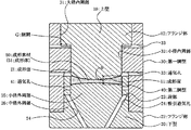
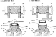
まず、本発明に係るモールドプレス成形型(以下、単に成形型という)の実施形態について、図1を参照して説明する。図1は、本実施形態に係る成形型の概略断面図であり、プレス荷重印加時の状態(図4(8)参照)を示している。
図1に示す成形型は、上型10、下型20、第一胴型30及び第二胴型40を備えて構成され、上型10と下型20との間で成形素材50をプレス成形する。
[Mold press mold]
First, an embodiment of a mold press mold (hereinafter simply referred to as a mold) according to the present invention will be described with reference to FIG. FIG. 1 is a schematic cross-sectional view of a mold according to the present embodiment, showing a state when a press load is applied (see FIG. 4 (8)).
1 includes an
本実施形態において、第一胴型30は、成形型を組み立てる際や、プレス成形の際に、上下型10,20を摺動ガイドすることにより、これらの水平方向の相対位置を規制して、上下型10,20の同軸性を確保する。
すなわち、第一胴型30は、上下型10,20のそれぞれと直接接触して摺動ガイドし、また、接触部分のクリアランスを充分に小さい数値に制御することによって、上下型10,20の高度な同軸性を得ることができる。
In the present embodiment, the
That is, the
このため、第一胴型30と上下型10,20の摺動クリアランスは、要求される光学素子の偏心精度を考慮すると10μm以下、特に、5μm以下とすることが好ましい。上記摺動クリアランスを制御すれば、上下型10,20の成形面11,21間の偏心(シフト:上下型10,20の成形面11,21の水平方向のずれ、ティルト:上下型10,20の軸の傾き)を高精度に抑制できる。
特に、本実施形態においては、第一胴型30が、上型10の成形面11の外周を接触包囲するとともに、下型20の成形面21の外周近傍を接触包囲して、上下型10,20を位置決めするため、上下型10,20の相互の位置ずれ(シフト)が抑制可能である。すなわち、第一胴型30が、上下型10,20の同軸性を高く維持できるように、後述の第二胴型40の配置がなされているのである。
For this reason, the sliding clearance between the
In particular, in this embodiment, the
本実施形態では、プレス成形の際に、第一胴型30内に嵌合された下型20に対して、上型10が第一胴型30内を摺動ガイドされ、上下型10、20が相対的に接近、離間するように構成した例について説明するが、これとは逆に構成することもできる。すなわち、第一胴型30内に嵌合された上型10に対して、下型20が第一胴型30内を摺動ガイドされるようにしてもよく、上下型10,20が、その同軸性を確保しつつ、相対的に近接、離間するようになっていれば、その具体的な構成は制限されない。
In this embodiment, the
このような第一胴型30には、上下型10、20が接近、離間するときに、型内外の気圧差によって、上下型10,20の動きが妨げられないようにするための通気孔33を設けておくのが好ましい。特に、本実施形態では、図示するように、第一胴型30の内径が変化して段部となっている部位に通気孔33を設け、この段部の隙間における体積の増減に対して、成形型内部が常に外圧と等しくなるように、通気孔33を介して雰囲気ガスの導通が行われるようにするのが好ましい。また、第一胴型内に収容される第二胴型40にも、第一胴型30と同様の目的で通気孔41を設けることが好ましい。これにより、プレス成形や成形型の組立・分解をスムーズに行えるようになる。
The
上型10は、下型20と対向する下面に成形面11が形成されている。図1に示す例において、成形面11は、凸面となっているが、凹面又は平面であってもよい。また、上型10の上部には、成形面11より径の大きいフランジ部12が形成されており、このフランジ部12が、第一胴型30の上部に形成された大径内周部31に収容される。
The
このとき、上型10の上面と、第一胴型30の上面とが同一面となったときに、上型10に形成されたフランジ部12の下面と、第一胴型30に形成された小径内周部32の上端との間には、所定寸法以上の隙間Gが確保されるようにするのが好ましい。このような隙間Gを確保することにより、プレス成形の際に、上型10を、その上面が第一胴型30の上面と一致するまで押し込んで、いったん成形体15の肉厚を決めた後であっても、成形体51に必要な荷重(上型10の自重のみでもよい)を付与し続けることができ、成形体51の熱収縮に追従した上型10の下降を許容することができる(図4(8)及び図5(9)参照)。
At this time, when the upper surface of the
下型20の上型10と対向する上面には、凸面を有する成形面21が形成されている。また、下型20の下部には、成形面21より径の大きいフランジ部22が形成されている。プレス成形の際に、このフランジ部22の上面に第一胴型30の下面が当接し、かつ、プレス圧によって互いに密着されることにより、下型20と第一胴型30の相互位置が高精度に画定され、これによってもティルトが抑制される。
A
さらに、下型20の上部側には、成形面21の外径とほぼ同じ外径をもつ小径外周部25と、この小径部25とフランジ部22との中間の外径をもつ中径外周部26とが形成されている。これとともに、小径外周部25と中径外周部26の境界(すなわち、下型20の成形面21の周囲であって、下型20の成形面21よりも低い位置)には、第二胴型40を保持するための段部23が形成されている。
段部23に保持された第二胴型40は、その外径が下型20の中径外周部26の外径と同等、又はそれより小さいことが好ましい。これにより、第二胴型40は、第一胴型30による下型20の摺動ガイドを阻害せず、上下型10,20の同軸性を劣化させない。
Further, on the upper side of the
It is preferable that the outer diameter of the
第一胴型30の内周部に収容される第二胴型40は、狭いクリアランスで下型20の小径外周部25に外嵌されることにより、その水平方向の位置が規定され、これとともに、段部23によって上下位置が規定される。これにより、下型20における成形面21の外周が、第二胴型40によって包囲されるようになっている。
このとき、前述した第二胴型40に設ける通気孔41は、プレス成形中に成形素材50が通気孔41に侵入しない位置に設けるものとし、具体的には、第二胴型40を段部23に保持させた状態において、第二胴型40の軸方向における下型20の成形面21の周縁部と段部23の中間に位置するところに設けるのが好ましい。
The
At this time, the vent hole 41 provided in the second barrel die 40 is provided at a position where the
図示する例において、通気孔41は、第二胴型40をほぼ半径方向に貫通するように設けられ、第二胴型40の内周面と下型20とのクリアランスや、第二胴型40の外周面と胴型30とのクリアランス、及び通気孔33と連通している。これにより、成形素材50と下型成形面21との間の空間に存在する雰囲気ガスが上下型10,20の近接(プレス成形)によって圧縮されるときに、成形型内の雰囲気ガスを、第二胴型40の内周面と下型20とのクリアランス、第二胴型40の通気孔41、第二胴型40の外周面と胴型30とのクリアランス、第一胴型30の通気孔33を経由して成形型の外部へ放出することができる。
したがって、このような通気孔41を設けることにより、雰囲気ガスを成形型の外部へ放出させることで、成形型内部と外圧とを均衡させることができる。
In the illustrated example, the vent hole 41 is provided so as to penetrate the second barrel die 40 in the almost radial direction, and the clearance between the inner peripheral surface of the second barrel die 40 and the
Therefore, by providing such a vent hole 41, it is possible to balance the inside of the mold and the external pressure by releasing the atmospheric gas to the outside of the mold.
第二胴型40は、下型20の成形面21上に載置された成形素材50の外周部を包囲することで成形面21上における成形素材50の位置ずれを規制する。特に、本実施形態のように下型20の成形面が凸型の場合、第二胴型40は成形素材50の滑落を抑止することもできる。
このため、第二胴型40の形状や寸法は、成形素材50の位置ずれや滑落を防止するのに十分なものであれば特に制限されないが、下型20の小径外周部25に狭いクリアランスで外嵌できる内径を備えるとともに、下型20の成形面21上に突出する部分の高さが、成形素材50の最大径部分(外周部)の厚みとほぼ同等、又はそれ以上の高さであるのが好ましい。
The
For this reason, the shape and dimensions of the
ここで、下型20の小径外周部25の外周と、第二胴型40の内周とのクリアランスは、50μm以下、より好ましくは30μm以下とすることが好ましく、そのようにすることで、下型20の小径外周部25と第二胴型40との隙間に成形素材50が入り込んでしまうのを抑止できる。
Here, the clearance between the outer periphery of the small-diameter outer peripheral portion 25 of the
ところで、第二胴型40の高さが大きすぎると、下型20の成形面21上に突出する部分が高すぎてしまい、プレス成形の際に、上型10を摺動ガイドするのに供される第一胴型30の大径内周部31や、小径内周部32の高さ(摺動ガイド長)が相対的に小さくなり、成形体の偏心(特にティルト)精度を得にくくなってしまうというような不都合が生じる。これは、第一胴型30内で許容される上型10の倒れ角は、第一胴型30と上型10との間の摺動クリアランスと、摺動ガイド長によって決まるため、摺動クリアランスが一定であれば、摺動ガイド長をより大きくするほど、上型10の倒れが抑制され、上下型10、20の同軸性が良好になり、光学素子としての成形体の偏心精度を高くすることができるのに対して、摺動ガイド長が小さくなると、このような上型10の倒れを抑制する効果が損なわれてしまうからである。第二胴型40の具体的な寸法は、このような点を考慮して決定される。
By the way, if the height of the
したがって、より好ましくは、第二胴型40の下型20の成形面21上に突出する部分の高さは、第一胴型30における摺動ガイド長を考慮して、得ようとする成形体51の形状や寸法などとの関係から、成形に支障を来さない範囲でできるだけ低くなるように設定する。例えば、得ようとする成形体51の外周部の肉厚をhとするとき、下型20の成形面21上に突出する部分の高さは、0.9hを超え、1.2h未満であるのが好ましい。また、プレス成形後に芯取り加工を行わない場合には、第二胴型40の内周面が光学素子の外周を成形するので、下型20の成形面21上に突出する部分の高さは、1.0hを超え、1.2h未満であるのが好ましい。
Therefore, more preferably, the height of the portion protruding on the
ここで、第二胴型40の高さが過度に大きくないことは、第二胴型40が配置された下型20上に成形素材50を供給する際、及び、成形後に成形体51を取り出す際に、成形素材50や成形体51を吸着、搬送するロボットなどと干渉が生じない点でも有利である。
Here, the fact that the height of the
また、第二胴型40は、少なくとも、プレス成形後における成形体51の取り出し時に、下型20と一体的に保持されるのが好ましい。これにより、第二胴型40が成形体51に付着して、成形体51とともに成形型から取り出されてしまうのを防止することができる。
このとき、第二胴型40と下型20とを一体のものとして、下型20(特に、成形面21)を精密加工することは困難である。このため、第二胴型40と下型20を別体に加工し、これらを一体的に組み合わせて使用するのが効率的である。よって、プレス成形後における成形体51の取り出し時に、別体に加工された第二胴型40と下型20とを一体的に保持する保持手段を用いることが好ましい。
Further, it is preferable that the
At this time, it is difficult to precisely process the lower mold 20 (particularly the molding surface 21) by integrating the
このような保持手段としては、例えば、第二胴型40と下型20をピンなどにより機械的に固定又は拘束(遊びのある拘束でもよい)するものが挙げられる。しかしながら、小型又は薄肉の光学素子(最大肉厚が1〜3mm程度)を成形する場合などには、第二胴型40や下型20のサイズに制限があるため、ピン穴を穿つことが困難であることなどを考慮すると、下型20及び/又は第二胴型40に吸引通気孔を設け、雰囲気ガスの吸引によって、下型20と第二胴型40とを相互に密着させることにより、第二胴型40と下型20とが一体的に保持されるようにするのが好ましい。
Examples of such holding means include one that mechanically fixes or restrains the
この場合、特に、下型20の底面と、第二胴型40を保持する段部23とを連通する吸引通気孔24を設け、この吸引通気孔24を通じて雰囲気ガスを吸引することにより、第二胴型40を下型20に密着させることが好ましい。このような雰囲気ガスの吸引によって、第二胴型40と下型20とを一体的に保持すると、吸引通気孔24を設けるだけの簡易な構成により、成形型を分解して上下型10,20を離間させる際に、成形体51と第二胴型40とが上型10側に付着することを防止できるとともに、成形体51の取出し時に、成形体51のみを下型20及び第二胴型40から分離して取り出すことが可能となる。
なお、吸引のための排気手段は、成形型の組立・分解に際して、成形型を載置する載置台70上に、成形型(下型20)を密着、固定させるための既存の設備をそのまま利用できる(図3等参照)。
In this case, in particular, by providing a
The exhaust means for suction uses existing equipment for attaching and fixing the molding die (lower die 20) on the mounting table 70 on which the molding die is placed when assembling and disassembling the molding die. Yes (see FIG. 3 etc.).
本発明において、上型10、下型20、第一胴型30及び第二胴型40の素材には特に制限はない。炭化ケイ素、ケイ素、窒化ケイ素、炭化タングステン、酸化アルミニウムや炭化チタンのサーメット又は、これらの表面にダイヤモンド、耐熱金属、貴金属合金、炭化物、窒化物、硼化物、酸化物などを被覆したものを挙げることができる。
上下型10,20の成形面11、21には、ガラスの融着を防止するために、非晶質及び/又は結晶質のグラファイト及び/又はダイヤモンドの単一成分層又は混合層からなる炭素膜、又は貴金属合金による離型膜などを用いることが好ましい。また、プレス成形後に、成形体51に芯取り加工(成形体51の外周を切除するとともに、外径中心を光学的な中心と一致させる加工)を施さない場合には、第二胴型40の内周が成形体の外縁部に転写され、その被転写面が最終的に得ようとする光学素子の外縁となるため、第二胴型40の内周には、ガラスの融着を防止する表面処理(例えば、離型膜の成膜など)を行うことが好ましく、上記と同様の素材が利用できる。
In the present invention, the material of the
On the molding surfaces 11 and 21 of the upper and
また、本発明に用いる成形素材50の材料には特に制限はない。例えば、ガラスプリフォームなどのガラス素材とすることができる。
成形素材50の形状は、例えば、ブロック状の光学ガラスを、切断、研磨して、円盤状、球形状などに加工(冷間加工)したもの、又は溶融状態から受け型上に滴下、又は流下することによって、球状、両凸曲面形状などに予備成形(熱間成形)したものとすることができる。本発明においては、冷間加工した円盤状のガラス素材、又は熱間成形した両凸曲面形状、又は熱間成形の後、さらに熱間で平面又は凹面を加工するなどの予備成形をしたガラス素材が好ましい。
特に、成形素材50の外周を支承する第二胴型40の高さが過度に高くなることは、上記のとおり不利である点を考慮すると、第二胴型40の高さを比較的小さくできることから、成形素材50は、下面側が平面、又は凹面であるのが好ましい。
Moreover, there is no restriction | limiting in particular in the material of the shaping | molding
The shape of the
In particular, when the height of the
成形素材50の径は、得ようとする成形体51の径より小さいことが必要であり、わずかに小さいことが好ましい。このようにすると、第二胴型40の内径よりわずかに小さい径となり、下型20上における成形素材50の偏在が回避されるので、プレス成形時に偏肉が生じにくくなる。例えば、得ようとする成形体51の径に対し、90〜99%のものが好ましい。
なお、成形型から取り出された成形体51は、芯取り加工を行うこともできるが、本実施態様によれば、成形体51の外周面は、第二胴型40の内周を転写したものとすることができるため、成形体51の外周面には、不要な突起や不定形な自由表面などの形成が抑止される。したがって、本実施形態における成形型によって得られた成形体51は、芯取り加工などの後加工を必要とせず、そのままで最終的に得ようとする光学素子の形状とすることができる。
The diameter of the
The molded
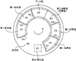
次に、本発明に係る成形型を用いてプレス成形を行うのに適したモールドプレス成形装置(以下、単に成形装置という)について、図2を参照して説明する。図2は、このような成形装置の一例として示す回転移送式の成形装置の概略平面図である。 Next, a mold press molding apparatus (hereinafter simply referred to as a molding apparatus) suitable for performing press molding using the molding die according to the present invention will be described with reference to FIG. FIG. 2 is a schematic plan view of a rotary transfer molding apparatus shown as an example of such a molding apparatus.
図2に示す成形装置は、取出・挿入室P1と、周方向に並べて配置された多数の処理室P2〜P8を備えている。
取出・挿入室P1では、成形を終えた成形型の取り出し作業と、新たに成形に供される成形素材を収容した成形型の挿入作業が行われる。取出・挿入室P1から挿入された成形型は、図中矢印方向に回転する回転テーブルに取り付けられた保持台に保持されるなどして、成形素材(又は成形体)を収容した様態で、常時非酸化性ガスの雰囲気(不活性ガス雰囲気)下にある処理室P2〜P8の中を順次通過するようになっている。回転テーブルは、一定時間ごとに間歇的に回転し、この間歇的な回転により、隣設された処理室間を成形型が移動する。そして、この一定時間が、成形サイクルタイムとなる。
The molding apparatus shown in FIG. 2 includes an extraction / insertion chamber P1 and a large number of processing chambers P2 to P8 arranged side by side in the circumferential direction.
In the take-out / insertion chamber P1, an operation of taking out the molding die that has been molded and an operation of inserting a molding die that contains a molding material to be newly used for molding are performed. The molding die inserted from the take-out / insertion chamber P1 is always held in a state in which a molding material (or molded body) is accommodated, for example, by being held on a holding table attached to a rotary table that rotates in the direction of the arrow in the figure. It sequentially passes through the processing chambers P2 to P8 under a non-oxidizing gas atmosphere (inert gas atmosphere). The rotary table rotates intermittently at regular intervals, and the mold moves between adjacent processing chambers by this intermittent rotation. And this fixed time becomes a molding cycle time.
ここで、P2は第一加熱室、P3は第二加熱室、P4は第三加熱室(又は均熱室)であり、これらは総称して加熱部ともいう。P5はプレス室であり、加熱部でプレス成形に適した温度とされた成形型へのプレス荷重の印加が行われる。P6は第一徐冷室、P7は第二徐冷室、P8は急冷室であり、これらは総称して冷却部ともいい、プレス荷重が印加された後の成形型の冷却処理が行われる。これらの処理室P2〜P8は、略等間隔に配置されており、それぞれの処理に適した温度に温度制御されるとともに、各処理室内の温度を所定温度に保つために、シャッターS1〜S6によって区画されている。 Here, P2 is a first heating chamber, P3 is a second heating chamber, and P4 is a third heating chamber (or soaking chamber), which are also collectively referred to as a heating unit. P5 is a press chamber, and a press load is applied to a mold set at a temperature suitable for press molding in the heating section. P6 is a first slow cooling chamber, P7 is a second slow cooling chamber, and P8 is a rapid cooling chamber. These are also collectively referred to as a cooling section, and the mold is cooled after a press load is applied. These processing chambers P2 to P8 are arranged at substantially equal intervals, and are controlled to a temperature suitable for each processing, and in order to keep the temperature in each processing chamber at a predetermined temperature, shutters S1 to S6 are used. It is partitioned.
図2に示すような成形装置を用いれば、成形素材(又は成形体)が収容された成形型を、各処理室を順次移送しながら適切な処理を施すことによって、所望の光学素子を効率よく製造することができる。
すなわち、プレス成形に適した温度への成形型の昇温、プレス荷重の印加、その後の冷却処理が、二次元的に配置された各処理室を成形型が通過することによって行われるため、多数の成形型を同時に使用でき、個々の成形に必要な実質時間(成形サイクルタイム)が短縮される。
なお、前述したように、回転テーブルが間歇的に回転し、隣設された処理室間を成形型が移動するのに要する時間が、成形サイクルタイムとなる。
If a molding apparatus as shown in FIG. 2 is used, a desired optical element can be efficiently obtained by subjecting a mold containing a molding material (or molded body) to appropriate processing while sequentially transporting each processing chamber. Can be manufactured.
That is, since the temperature of the mold is increased to a temperature suitable for press molding, press load is applied, and the subsequent cooling process is performed by the mold passing through each processing chamber arranged two-dimensionally. These molding dies can be used at the same time, and the actual time (molding cycle time) required for each molding is shortened.
As described above, the time required for the rotary table to rotate intermittently and the mold to move between adjacent processing chambers is the molding cycle time.
本発明に係る成形型は、加熱室、プレス室、冷却室などの各処理室に、成形素材(又は成形体)が収容された成形型を移送して、加熱、プレス、冷却を含む適切な処理を順次施す成形装置において好適に用いられるが、このような成形装置の具体的な構成は、上記した例には制限されない。例えば、上記した例では、回転テーブルにより成形型を移送するようにしているが、二次元的(場合によっては三次元的)に配置された各処理室内を所定の時間間隔で通過できるように構成されているものであれば、成形型を移送する手段は特に制限されない。 The molding die according to the present invention is suitable for heating, pressing, and cooling by transferring the molding die containing the molding material (or molded body) to each processing chamber such as a heating chamber, a press chamber, and a cooling chamber. Although it is preferably used in a molding apparatus that sequentially performs processing, the specific configuration of such a molding apparatus is not limited to the above-described example. For example, in the above-described example, the mold is transferred by the rotary table, but it is configured so that it can pass through each processing chamber arranged two-dimensionally (in some cases three-dimensionally) at a predetermined time interval. If it is what is carried out, the means in particular to transfer a shaping | molding die will not be restrict | limited.
また、各処理室の配置構成は、成形素材の組成や、得ようとする成形体の形状にあわせて、加熱工程や冷却工程を最適化するために適宜変更することができる。例えば、加熱室を四つにしたり、冷却室を三つにしたりするなどの変更を行うことができる。また、生産効率をさらに向上させるために、加熱室、プレス室、冷却室などをそれぞれ同数連設し、異なる温度条件、異なる加圧条件を要する複数種類のプレス成形を同時並行的に行うようにしてもよい。 Moreover, the arrangement configuration of each processing chamber can be appropriately changed in order to optimize the heating process and the cooling process in accordance with the composition of the molding material and the shape of the molded body to be obtained. For example, it is possible to make changes such as four heating chambers or three cooling chambers. In order to further improve production efficiency, the same number of heating chambers, press chambers, and cooling chambers are provided in series, and multiple types of press molding that require different temperature conditions and different pressurization conditions are performed simultaneously. May be.
また、生産効率を向上させるためには、例えば、同一の工程に供される複数の保持台が各処理室を同時に通過するようにするなどして、各処理室の中で成形型を複数個ずつ同時に処理することもできる。具体的には、各処理室において、加熱、プレス荷重の印加、冷却処理等の処理が行われるときに、成形型を進行方向に2個以上配列し、それらに対して同時に同じ処理を施すことができる。この場合、プレス室には、進行方向に配列した二以上のプレス手段を設けることが好ましい。 Further, in order to improve production efficiency, for example, a plurality of molds are provided in each processing chamber by, for example, allowing a plurality of holders used in the same process to pass through each processing chamber at the same time. They can be processed simultaneously. Specifically, when processing such as heating, application of a press load, and cooling processing is performed in each processing chamber, two or more molds are arranged in the traveling direction, and the same processing is simultaneously performed on them. Can do. In this case, the press chamber is preferably provided with two or more pressing means arranged in the traveling direction.
[光学素子の製造方法]
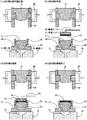
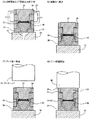
次に、本発明に係る光学素子の製造方法の実施形態について、図1に示す成形型を、図2に示す成型装置に適用して実施する例に基づき、図3〜図6を参照して説明する。図3は、本実施形態に係る光学素子の製造方法における工程(1)〜(4)を示す説明図、図4は、同工程(5)〜(8)を示す説明図、図5は、同工程(9)〜(12)を示す説明図、図6は、同工程(13)〜(14)を示す説明図である。
[Method for Manufacturing Optical Element]
Next, referring to FIG. 3 to FIG. 6, based on an example in which the molding die shown in FIG. 1 is applied to the molding apparatus shown in FIG. explain. 3 is an explanatory view showing steps (1) to (4) in the method of manufacturing an optical element according to the present embodiment, FIG. 4 is an explanatory view showing the steps (5) to (8), and FIG. FIG. 6 is an explanatory view showing the steps (9) to (12), and FIG. 6 is an explanatory view showing the steps (13) to (14).
工程(1)〜(4):成形素材供給工程
下型20及び第二胴型40が、載置台70上に一体的に保持され、上型10及び第一胴型30と離間した状態で待機している成形型に対し(図3(1)参照)、吸着パッド61付の搬送アーム60によって成形素材(例えば、ガラスプリフォーム)50を供給する(図3(2)参照)。吸着パッド61が、所定範囲内の精度で下型20の成形面21上に到達し(図3(3)参照)、その吸着を解除することによって、成形素材50は、下型20の成形面21上に載置される(図3(4)参照)。このとき、成形素材50は、外周部が第二胴型40によって支承されることによって、滑落することなく下型20の成形面21上に保持される。
Steps (1) to (4): Molding material supply step The
なお、成形素材50を供給するに際しては、予め吸着パッド61の中心と成形素材50の中心の位置合わせが行われた状態で、かつ、吸着パッド61の中心と下型20の成形面21の中心が実質的に一致した状態で、成形素材50が保持部材40に載置されるように、搬送アーム60の動作を制御するのが好ましく、搬送アーム60は、成形素材50を供給した後に直ちに退避する。また、上型10が組み込まれた胴型30は、保持手段80により、その位置が固定されている。
When the
工程(5):成形型の組立工程
成形素材50が下型20の成形面21上に載置されると、載置台70が上昇し、下型20と第二胴型40とが、第一胴型30内に組み込まれる(図4(5)参照)。このとき、第一胴型30と下型20のクリアランスは、5μm以下とされていることが好ましい。また、予め組み立てられた上型10と第一胴型30も同様のクリアランスとするのが好ましい。これにより、上下型10,20の成形面11,21間の偏心を高精度に抑制できる。
第一胴型30内に、下型20と第二胴型40とが組み込まれ、第一胴型30の下面に下型20のフランジ部22の上面が当接すると、図4(5)に示すように、成形素材50の厚みによって、上型10の上面が、第一胴型30の上面より高い位置に押し上げられる。
なお、成形型を組み立てるに際しては、載置台70を上昇させるかわりに、保持手段80により上型10及び第一胴型30を下降させるようにしてもよい。
Step (5): Assembling step of molding die When the
When the
When assembling the forming die, the
上記の工程(1)〜(5)においては、下型20が載置台70上で位置ずれを起こさないように、載置台70に設けられた開口部71から雰囲気ガスを吸引することにより載置台70上に下型20を密着、固定することができる。このとき、開口部71と下型20に設けた吸引通気孔24とを連通させ、この吸引通気孔24を通じて雰囲気ガスを吸引すれば、第二胴型40を下型20に密着させることもできる。
このように、下型20を成形型の載置台70に密着、固定させる目的で設けられる既存の排気手段を利用することにより、載置台70、下型20及び第二胴型40を一体的に保持することができる。そして、後述するように、成形型を分解する際に、雰囲気ガスの吸引により載置台70上に下型20を密着、固定し、第一胴型30から下型20を抜き出した時の位置を維持することで、下型20と第一胴型30の水平方向の相対位置がずれてしまうのを避けることができ、さらに、成形体51を取り出す際にも、第二胴型40を下型20に吸引密着させることで、成形体51とともに第二胴型40が成形型から取り出されてしまうことを防止して、成形体51のみを取り出すことができるようになる。
In the above steps (1) to (5), the mounting table is obtained by sucking the atmospheric gas from the
In this way, the mounting table 70, the
なお、上記の工程(1)〜(5)にしたがって、成形素材50を収容して組み立てられた成形型は、図2に示す成形装置において、取出・挿入室P1から成型装置内に挿入されるが、上記の工程(1)〜(5)は、取出・挿入室P1内で行うようにしてもよい。
In addition, according to said process (1)-(5), the shaping | molding die accommodated and assembled with the shaping | molding
工程(6):加熱工程
成形素材50が収容され、成形装置内に挿入された成形型を、回転テーブルに取り付けられた保持台75に保持させるなどして、加熱室P2〜P4に順次移送しつつ、加熱する(図4(6)参照)。これによって、成形型ごと成形素材50をプレス成形に適した温度に昇温する。
このとき、例えば、第一加熱室P2は、成形素材50のプレス温度以上の高温に保ち、成形型及び成形素材50を急速に加熱する。そして、成形素材50が収容された成形型は、第一加熱室P2で所定時間静止した後、回転テーブルの回転に応じて第二加熱室P3に移送される。この第二加熱室P3での加熱により、成形型と成形素材50は、さらに加熱されながら、均熱化されてプレス温度に近づく。次いで、第三加熱室P4で成形型と成形素材50を均熱化して、成形素材50の粘度をプレス成形に適切な106〜109ポアズにするが、好ましくは、成形素材50の温度は、106〜108ポアズの粘度となる温度となるように設定する。
なお、加熱室P2〜P4が備える加熱手段には特に制限はない。例えば、抵抗加熱によるヒータ、高周波誘導コイル等を用いることができる。
Step (6): Heating step The
At this time, for example, the first heating chamber P <b> 2 maintains a high temperature equal to or higher than the pressing temperature of the
In addition, there is no restriction | limiting in particular in the heating means with which the heating chambers P2-P4 are equipped. For example, a heater by resistance heating, a high frequency induction coil, or the like can be used.
工程(7)〜(8):プレス工程
適温になった成形型は、プレス室P5に移送される(図4(7)参照)。この移送の際、さらには、前述した成形型の組立工程から加熱工程への移送の際、成形型が振動したとしても、成形型内に収納された成形素材50は、第二胴型40によって径方向の移動が規制されているため、成形に支障を来たすような位置ずれを起こすことはない。
プレス室P5では、成形型の上方からプレスヘッド90により、所定圧力(例えば、30〜200Kg/cm2)、所定時間(例えば、数十秒)で、成形型にプレス荷重が印加される(図4(8)参照)。このとき、下型20と成形素材50との間の雰囲気ガスは、第二胴型40の通気孔41や第一胴型30の通気孔33を経由して成形型の外方へ放出される。
プレスヘッド90の下面が第一胴型30の上面に当接した時点で成形体51の肉厚が規定され、その後、プレスヘッド90を上昇させてプレス荷重の印加を解除することにより、プレス工程を終了する。
Steps (7) to (8): Pressing Step The mold that has reached an appropriate temperature is transferred to the press chamber P5 (see FIG. 4 (7)). During this transfer, and even when the mold is vibrated during the transfer from the assembly process of the mold described above to the heating process, the
In the press chamber P5, a press load is applied to the mold by a
When the lower surface of the
工程(9):冷却工程
プレス工程終了後、成形型は徐冷室P6、P7及び急冷室P8に順次移送され、冷却処理が施される(図5(9)参照)。
急冷室P8では、冷却用ガスによる急冷を行うことができ、成形体51がガラス転移点以下の温度となるまで冷却される。このとき、成形型には、上型10のフランジ部12の下面と、第一胴型30の小径内周部32の上端との間に、前述したような隙間Gを所定の寸法で確保しておくことにより、ガラスの収縮に対して上型10がその自重によって追随することが可能となり、良好な形状精度が得られる。
なお、ガラスの収縮に追随して上型10が降下したとき、上型10のフランジ部12と、第一胴型30の小径内周部32の上端面との間の隙間Gの間隔は狭くなる。
Step (9): Cooling Step After the pressing step, the mold is sequentially transferred to the slow cooling chambers P6 and P7 and the quenching chamber P8 and subjected to a cooling process (see FIG. 5 (9)).
In the quenching chamber P8, quenching with a cooling gas can be performed, and the molded
When the
工程(10)〜(11):成形型の分解工程
成形型が取出・挿入室P1に戻ってくると、成形型は、成型装置外に取り出され、成形型の分解、成形体51の取出し、さらには、新たな成形素材50の供給が行われる。
成形型の分解工程では、成形体51を収容した成形型は、ロボットにより載置台70に移送され(図5(10)参照)、周囲をチャックすることによって位置決めされる。そして、載置台70の開口部71から雰囲気ガスを吸引して、載置台70、下型20及び第二胴型40を一体的に保持した上で、載置台70を垂直に下降し、第一胴型30から下型20を抜き出して、上型10と下型20を離間させる(図5(11)参照)。第一胴型30から下型20を抜き出すときに、載置台70、下型20及び第二胴型40を一体的に保持し、第一胴型30から下型20を抜き出したときの位置を維持することで、下型20と第一胴型30の水平方向の相対位置がずれてしまうのを避けることができる。
このとき、前述した成形素材供給工程や、成形型の組立工程と同様に、上型10が組み込まれた胴型30は、保持手段80により、その位置が固定されている。
なお、不活性ガス雰囲気となっていない取出・挿入室P1にあっては、成形型の酸化防止を考慮して、成形型の温度が250℃以下となるように温度制御するのが好ましい。
Steps (10) to (11): Mold Disassembly Step When the mold returns to the take-out / insertion chamber P1, the mold is taken out of the molding apparatus, disassembled the mold, and removed the molded
In the step of disassembling the mold, the mold containing the molded
At this time, the position of the barrel die 30 in which the
In the take-out / insertion chamber P1 that is not in an inert gas atmosphere, it is preferable to control the temperature of the mold so that the temperature of the mold becomes 250 ° C. or less in consideration of prevention of oxidation of the mold.
工程(12)〜(14):光学素子の取出し工程
第一胴型30から下型20を抜き出した後に、搬送アーム60を上下型10、20間に挿入する(図5(12)参照)。そして、先端の吸着パッド61によって成形体51を吸引・吸着し(図6(13)参照)、下型20の成形面21上から成形体51を取り出す(図6(14)参照)。
このとき、雰囲気ガスの吸引により、第二胴型40を下型20に吸引密着させ、第二胴型40と下型20とを一体的に保持することにより、成形体51とともに第二胴型40が上昇するのを回避し、成形体51のみの取り出しが可能となる。
Steps (12) to (14): Optical Element Removal Step After the
At this time, the
これらの工程(1)〜(14)が終了した後は、工程(1)に戻り、上記のサイクルを繰り返すことによって、プレス成形を連続的に行うことができる。 After these steps (1) to (14) are completed, the process can be continuously performed by returning to the step (1) and repeating the above cycle.
以上のような本実施形態に係る光学素子の製造方法は、下型20の成形面21の外周を包囲する第二胴型40により、下型20の成形面21上に載置された成形素材50の外周部を包囲することで、成形面21上における成形素材50の位置ずれや滑落を防止するとともに、第一胴型30により上型10と下型20の水平方向の相対位置を規制しつつ、上型10と下型20とを接近させることによって、成形素材をプレス成形するものであるため、成形素材50の滑落を、大掛かりな可動部材を設けることなく防止でき、しかも、上型10と下型20の水平方向の相対位置を第一胴型30で高精度に規制し、偏心精度の高い光学素子を得ることができる。
The optical element manufacturing method according to the present embodiment as described above is a molding material placed on the
また、プレス成形後、成形型が載置台70に載置された状態で、載置台70、下型20及び第二胴型40を一体的に保持し、これらを上型10及び第一胴型30と離間させて、下型20の成形面21上から成形体51を取り出すので、プレス成形後における成形型の分解や、成形体の取り出しに際し、載置台70、下型20及び第二胴型40の位置関係を維持することができるだけでなく、成形体51とともに第二胴型40が成形型から取り出される不都合も防止できる。
しかも、本実施形態では、雰囲気ガスの吸引によって、載置台70、下型20及び第二胴型40を一体的に保持するので、サイズの小さい成形型でも実施できるだけでなく、既存の排気手段をそのまま利用することができる。
In addition, after the press molding, the mounting table 70, the
In addition, in the present embodiment, the mounting table 70, the
また、成形型が、加熱室、プレス室、冷却室を含む複数の処理室に移送され、それぞれの処理室で加熱、プレス、冷却を含む処理が施されることによって、成形型の内部に収容した成形素材50がプレス成形されるので、多数の成形型を同時に使用しつつ、成形型の昇温や降温を効率良く行い、個々の成形に必要な実質時間(成形サイクルタイム)を短縮することができる。そして、本実施形態における成形型は、大掛かりな可動部材を設けることなく、成形素材50の位置ずれや滑落を防止するので、このような製造方法を好適に用いることができる。
In addition, the mold is transferred to a plurality of processing chambers including a heating chamber, a press chamber, and a cooling chamber, and the processing including heating, pressing, and cooling is performed in each processing chamber, so that the mold is accommodated inside the molding die. Since the molded
以上、本発明について、好ましい実施形態を示して説明したが、本発明は、上記した実施形態にのみ限定されるものではなく、本発明の範囲で種々の変更実施が可能であることはいうまでもない。 Although the present invention has been described with reference to the preferred embodiments, the present invention is not limited to the above-described embodiments, and various modifications can be made within the scope of the present invention. Nor.
本発明は、ガラス等の成形素材を、精密加工を施した上型及び下型によってプレス成形し、被成形面に対する研磨などの後加工を必要としないモールドプレス成形型、及びこのモールドプレス成形型を用いた光学素子の製造方法に適用することができる。 The present invention relates to a mold press mold that does not require post-processing such as polishing on a surface to be molded, by press-molding a molding material such as glass with an upper mold and a lower mold subjected to precision processing, and this mold press mold It can apply to the manufacturing method of the optical element using this.
10 上型
11 成形面
20 下型
21 成形面
24 吸引通気孔
30 第一胴型
40 第二胴型
50 成形素材
51 成形体
70 載置台
71 開口部
P2 第一加熱室
P3 第二加熱室
P4 第三加熱室
P5 プレス室
P6 第一徐冷室
P7 第二徐冷室
P8 急冷室
10 Upper mold 11
Claims (7)
前記下型は、凸面を有する成形面が形成された小径外周部と、前記成形面より径の大きいフランジ部と、前記小径外周部と前記フランジ部との中間の径を有する中径外周部と、前記小径外周部と前記中径外周部との境界に形成された段部とを備え、
前記第一胴型が、前記下型の中径外周部を摺動ガイドして、前記上型と前記下型の水平方向の相対位置を規制し、
前記第二胴型が、前記下型の小径外周部に狭いクリアランスで外嵌できる内径を備え、前記下型の成形面の外周を包囲するように前記下型の段部に保持され、かつ、前記下型の成形面上に載置される成形素材の外周部の少なくとも一部を支承して、前記成形素材の位置ずれを規制し、
前記下型には、前記下型の底面と前記段部とを連通し、雰囲気ガスの吸引によって、前記第二胴型を前記下型に吸引密着させ、前記第二胴型と前記下型を一体的に保持するための吸引通気孔が形成されていることを特徴とするモールドプレス成形型。 A lower mold having a molding surface, an upper mold having a molding surface facing the molding surface of the lower mold, and a first body mold that allows the upper mold and the lower mold to be inserted from both ends. And a second cylinder mold accommodated in the first cylinder mold, a mold press mold for press molding a molding material between the upper mold and the lower mold,
The lower mold includes a small-diameter outer peripheral portion on which a molding surface having a convex surface is formed, a flange portion having a larger diameter than the molding surface, and a medium-diameter outer peripheral portion having an intermediate diameter between the small-diameter outer peripheral portion and the flange portion. A step portion formed at a boundary between the small-diameter outer peripheral portion and the medium-diameter outer peripheral portion,
The first body mold is configured to slide and guide the outer peripheral portion of the inner diameter of the lower mold to regulate the relative position in the horizontal direction between the upper mold and the lower mold,
The second body mold has an inner diameter that can be fitted with a small clearance on the outer periphery of the lower diameter of the lower mold, is held by the step of the lower mold so as to surround the outer periphery of the molding surface of the lower mold , and Supporting at least a part of the outer peripheral portion of the molding material placed on the molding surface of the lower mold to regulate the displacement of the molding material ,
The lower die communicates with the bottom surface of the lower die and the stepped portion, and the second barrel die and the lower die are brought into close contact with the lower die by suction of atmospheric gas. press-molding mold, characterized that you have been formed is suction vent to hold together.
前記下型に、凸面を有する成形面が形成された小径外周部と、前記成形面より径の大きいフランジ部と、前記小径外周部と前記フランジ部との中間の径を有する中径外周部と、前記小径外周部と前記中径外周部との境界に形成された段部と、前記下型の底面と前記段部とを連通する吸引通気孔とを設けておくとともに、
前記下型の小径外周部に狭いクリアランスで外嵌できる内径を備える前記第二胴型を前記下型の成形面の外周を包囲するように前記下型の段部に保持させ、
前記上型と前記下型を離間させた状態で、前記下型成形面上に成形素材を載置し、載置された前記成形素材の外周部の少なくとも一部を、前記下型成形面の外周を包囲する前記第二胴型によって支承して前記成形素材の位置ずれを規制し、
前記第一胴型により前記下型の中径外周部を摺動ガイドして、前記上型と前記下型の水平方向の相対位置を規制しつつ、前記上型と前記下型とを接近させることによって、成形素材をプレス成形し、
プレス成形後、前記下型の吸引通気孔から雰囲気ガスを吸引することによって、前記第二胴型を前記下型に吸引密着させ、前記第二胴型前と前記下型を一体的に保持した上で、前記第一胴型から前記下型を抜き出して、前記上型と前記下型を離間させ、その後、前記下型の成形面上から成形体を取り出すことを特徴とする光学素子の製造方法。 A lower mold in which a molding surface is formed; an upper mold in which a molding surface opposite to the molding surface of the lower mold is formed; and a first body mold that allows the upper mold and the lower mold to be inserted from both ends. A method of manufacturing an optical element that press-molds a molding material between the upper mold and the lower mold using a mold press mold including a second cylinder mold accommodated in the first cylinder mold,
A small-diameter outer peripheral portion in which a molding surface having a convex surface is formed on the lower mold, a flange portion having a diameter larger than the molding surface, and a medium-diameter outer peripheral portion having a diameter intermediate between the small-diameter outer peripheral portion and the flange portion. In addition, a step portion formed at the boundary between the small-diameter outer peripheral portion and the medium-diameter outer peripheral portion, a suction vent hole that communicates the bottom surface of the lower mold and the step portion, and
Holding the second body mold having an inner diameter that can be fitted with a small clearance on the outer periphery of the lower diameter of the lower mold on the step of the lower mold so as to surround the outer periphery of the molding surface of the lower mold;
With the upper mold and the lower mold spaced apart, a molding material is placed on the lower mold molding surface, and at least a part of the outer periphery of the placed molding material is placed on the lower mold molding surface. It is supported by the second body mold that surrounds the outer periphery to regulate the displacement of the molding material,
The first body mold slides and guides the middle-diameter outer peripheral portion of the lower mold so that the upper mold and the lower mold are brought close to each other while restricting the horizontal relative positions of the upper mold and the lower mold. By pressing the molding material ,
After press molding, atmospheric gas is sucked from the lower mold suction vents so that the second body mold is sucked and adhered to the lower mold, and the front of the second body mold and the lower mold are held together. The optical element is manufactured by extracting the lower mold from the first body mold, separating the upper mold from the lower mold, and then removing the molded body from the molding surface of the lower mold. Method.
プレス成形時に、前記成形素材と前記下型の成形面との間の雰囲気ガスを、前記通気孔を介して成形型の外部へ放出することを特徴とする請求項5に記載の光学素子の製造方法。6. The optical element according to claim 5, wherein an atmospheric gas between the molding material and the molding surface of the lower mold is released to the outside of the molding mold through the vent hole during press molding. Method.
Priority Applications (1)
| Application Number | Priority Date | Filing Date | Title |
|---|---|---|---|
| JP2005380559A JP4792141B2 (en) | 2005-01-19 | 2005-12-29 | Mold press mold and optical element manufacturing method |
Applications Claiming Priority (3)
| Application Number | Priority Date | Filing Date | Title |
|---|---|---|---|
| JP2005011989 | 2005-01-19 | ||
| JP2005011989 | 2005-01-19 | ||
| JP2005380559A JP4792141B2 (en) | 2005-01-19 | 2005-12-29 | Mold press mold and optical element manufacturing method |
Publications (2)
| Publication Number | Publication Date |
|---|---|
| JP2006225254A JP2006225254A (en) | 2006-08-31 |
| JP4792141B2 true JP4792141B2 (en) | 2011-10-12 |
Family
ID=36986940
Family Applications (1)
| Application Number | Title | Priority Date | Filing Date |
|---|---|---|---|
| JP2005380559A Expired - Fee Related JP4792141B2 (en) | 2005-01-19 | 2005-12-29 | Mold press mold and optical element manufacturing method |
Country Status (1)
| Country | Link |
|---|---|
| JP (1) | JP4792141B2 (en) |
Families Citing this family (1)
| Publication number | Priority date | Publication date | Assignee | Title |
|---|---|---|---|---|
| JP7103977B2 (en) * | 2019-03-04 | 2022-07-20 | Hoya株式会社 | Press molding equipment |
Family Cites Families (8)
| Publication number | Priority date | Publication date | Assignee | Title |
|---|---|---|---|---|
| JPH0585747A (en) * | 1991-09-27 | 1993-04-06 | Matsushita Electric Ind Co Ltd | Mold for molding glass lens and production of glass lens |
| JPH0572933U (en) * | 1992-03-06 | 1993-10-05 | オリンパス光学工業株式会社 | Mold holding device |
| JP3529904B2 (en) * | 1995-06-19 | 2004-05-24 | 鐘淵化学工業株式会社 | Process for producing optically active 1-halo-3-amino-4-phenyl-2-butanol derivative |
| FR2743792B1 (en) * | 1996-01-19 | 1998-03-13 | Saint Gobain Emballage | PROCESS AND DEVICE FOR HANDLING ARTICLES |
| JP3674910B2 (en) * | 1999-11-01 | 2005-07-27 | Hoya株式会社 | Method and apparatus for producing glass molded body |
| JP4090672B2 (en) * | 2000-06-29 | 2008-05-28 | Hoya株式会社 | Manufacturing method and apparatus for press-molded body and mold disassembling apparatus |
| JP2002167225A (en) * | 2000-11-29 | 2002-06-11 | Minolta Co Ltd | Metal mold for forming and forming method using it |
| DE10234234B4 (en) * | 2002-07-27 | 2006-04-27 | Schott Ag | Methods and apparatus for the molding of optical components |
-
2005
- 2005-12-29 JP JP2005380559A patent/JP4792141B2/en not_active Expired - Fee Related
Also Published As
| Publication number | Publication date |
|---|---|
| JP2006225254A (en) | 2006-08-31 |
Similar Documents
| Publication | Publication Date | Title |
|---|---|---|
| KR100839731B1 (en) | Mold press molding mold and optical device manufacturing method | |
| KR101272074B1 (en) | Mold press molding mold and method for producing optical element | |
| JP5904493B2 (en) | Glass forming apparatus and glass forming method | |
| JP4666677B2 (en) | Mold press mold and optical element manufacturing method | |
| JP5200074B2 (en) | Mold press molding apparatus and optical element manufacturing method | |
| JP4718864B2 (en) | Press mold and press molding method | |
| JP5021205B2 (en) | Mold press mold and optical element manufacturing method | |
| JP5021196B2 (en) | Mold press mold, optical element manufacturing method, and concave meniscus lens | |
| JP4792141B2 (en) | Mold press mold and optical element manufacturing method | |
| JP4303404B2 (en) | Manufacturing method and apparatus for press-molded body | |
| JP3869239B2 (en) | Optical element press molding apparatus and optical element manufacturing method | |
| JP6081225B2 (en) | Glass molded body manufacturing apparatus and glass molded body manufacturing method | |
| JP4695404B2 (en) | Mold assembly apparatus and optical element manufacturing method | |
| JP4711697B2 (en) | Optical element manufacturing method, mold press molding apparatus, and positioning apparatus used therefor | |
| JP4141983B2 (en) | Mold press molding method and optical element manufacturing method | |
| JP2005281053A (en) | Forming apparatus for mold press, method of manufacturing optical device, and optical device | |
| JP4939677B2 (en) | Optical element manufacturing method and mold press molding apparatus | |
| JP6726464B2 (en) | Optical element manufacturing method and optical element manufacturing apparatus | |
| JP4680738B2 (en) | Mold press molding apparatus and optical element manufacturing method | |
| JP2009007221A (en) | Method for forming optical element | |
| JP2016138037A (en) | Glass gob manufacturing method, glass gob manufacturing apparatus, optical element manufacturing method, and manufacturing method of lens blank for polishing | |
| JP2006143586A (en) | Method for drawing adsorber for formed body, method for drawing press formed body, and method for producing the same | |
| JP2004345943A (en) | Mold press molding device and method for producing optical element |
Legal Events
| Date | Code | Title | Description |
|---|---|---|---|
| A621 | Written request for application examination |
Free format text: JAPANESE INTERMEDIATE CODE: A621 Effective date: 20081119 |
|
| A977 | Report on retrieval |
Free format text: JAPANESE INTERMEDIATE CODE: A971007 Effective date: 20101122 |
|
| A131 | Notification of reasons for refusal |
Free format text: JAPANESE INTERMEDIATE CODE: A131 Effective date: 20101130 |
|
| A521 | Request for written amendment filed |
Free format text: JAPANESE INTERMEDIATE CODE: A523 Effective date: 20110131 |
|
| TRDD | Decision of grant or rejection written | ||
| A01 | Written decision to grant a patent or to grant a registration (utility model) |
Free format text: JAPANESE INTERMEDIATE CODE: A01 Effective date: 20110719 |
|
| A01 | Written decision to grant a patent or to grant a registration (utility model) |
Free format text: JAPANESE INTERMEDIATE CODE: A01 |
|
| A61 | First payment of annual fees (during grant procedure) |
Free format text: JAPANESE INTERMEDIATE CODE: A61 Effective date: 20110723 |
|
| FPAY | Renewal fee payment (event date is renewal date of database) |
Free format text: PAYMENT UNTIL: 20140729 Year of fee payment: 3 |
|
| R150 | Certificate of patent or registration of utility model |
Free format text: JAPANESE INTERMEDIATE CODE: R150 Ref document number: 4792141 Country of ref document: JP Free format text: JAPANESE INTERMEDIATE CODE: R150 |
|
| R250 | Receipt of annual fees |
Free format text: JAPANESE INTERMEDIATE CODE: R250 |
|
| R250 | Receipt of annual fees |
Free format text: JAPANESE INTERMEDIATE CODE: R250 |
|
| R250 | Receipt of annual fees |
Free format text: JAPANESE INTERMEDIATE CODE: R250 |
|
| R250 | Receipt of annual fees |
Free format text: JAPANESE INTERMEDIATE CODE: R250 |
|
| R250 | Receipt of annual fees |
Free format text: JAPANESE INTERMEDIATE CODE: R250 |
|
| R250 | Receipt of annual fees |
Free format text: JAPANESE INTERMEDIATE CODE: R250 |
|
| R250 | Receipt of annual fees |
Free format text: JAPANESE INTERMEDIATE CODE: R250 |
|
| LAPS | Cancellation because of no payment of annual fees |