JP3869239B2 - Optical element press molding apparatus and optical element manufacturing method - Google Patents
Optical element press molding apparatus and optical element manufacturing method Download PDFInfo
- Publication number
- JP3869239B2 JP3869239B2 JP2001300638A JP2001300638A JP3869239B2 JP 3869239 B2 JP3869239 B2 JP 3869239B2 JP 2001300638 A JP2001300638 A JP 2001300638A JP 2001300638 A JP2001300638 A JP 2001300638A JP 3869239 B2 JP3869239 B2 JP 3869239B2
- Authority
- JP
- Japan
- Prior art keywords
- molding
- optical element
- press
- molding surface
- preform
- Prior art date
- Legal status (The legal status is an assumption and is not a legal conclusion. Google has not performed a legal analysis and makes no representation as to the accuracy of the status listed.)
- Expired - Lifetime
Links
Images


Classifications
-
- C—CHEMISTRY; METALLURGY
- C03—GLASS; MINERAL OR SLAG WOOL
- C03B—MANUFACTURE, SHAPING, OR SUPPLEMENTARY PROCESSES
- C03B11/00—Pressing molten glass or performed glass reheated to equivalent low viscosity without blowing
- C03B11/06—Construction of plunger or mould
- C03B11/08—Construction of plunger or mould for making solid articles, e.g. lenses
-
- C—CHEMISTRY; METALLURGY
- C03—GLASS; MINERAL OR SLAG WOOL
- C03B—MANUFACTURE, SHAPING, OR SUPPLEMENTARY PROCESSES
- C03B35/00—Transporting of glass products during their manufacture, e.g. hot glass lenses, prisms
-
- C—CHEMISTRY; METALLURGY
- C03—GLASS; MINERAL OR SLAG WOOL
- C03B—MANUFACTURE, SHAPING, OR SUPPLEMENTARY PROCESSES
- C03B35/00—Transporting of glass products during their manufacture, e.g. hot glass lenses, prisms
- C03B35/005—Transporting hot solid glass products other than sheets or rods, e.g. lenses, prisms, by suction or floatation
-
- C—CHEMISTRY; METALLURGY
- C03—GLASS; MINERAL OR SLAG WOOL
- C03B—MANUFACTURE, SHAPING, OR SUPPLEMENTARY PROCESSES
- C03B2215/00—Press-moulding glass
- C03B2215/61—Positioning the glass to be pressed with respect to the press dies or press axis
-
- C—CHEMISTRY; METALLURGY
- C03—GLASS; MINERAL OR SLAG WOOL
- C03B—MANUFACTURE, SHAPING, OR SUPPLEMENTARY PROCESSES
- C03B2215/00—Press-moulding glass
- C03B2215/80—Simultaneous pressing of multiple products; Multiple parallel moulds
Description
【0001】
【発明の属する技術分野】
本発明は、予め予備成形したガラス素材を加熱軟化したのちプレス成形して所定形状の光学素子を得る光学素子のプレス成形装置及び光学素子の製造装置及び製造方法に関する。
【0002】
【従来の技術】
近年、光学レンズ等の製造分野では、表面研磨を行わずに高精度のレンズ形状を得るため、ガラス素材を予め所定の形状に予備成形したプリフォームを用意し、このプリフォームを加熱軟化させたのち、高精度なプレス面を持つ成形型を用いてプレス加工する方法が提案されている(特開2001−10829号等)。
【0003】
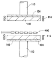
図6は、この種のプレス加工に用いられるプレス成形装置の基本構成を示すものである。図6に示したプレス成形装置は、上型602及び下型604により、複数(例えば4個)のプリフォームを一度にプレスするものである。上型602及び下型604は、いずれも図中左右方向に長い長尺形状を有している。上型602及び下型604の各対向面には、プリフォームにレンズ形状を付与するための複数の成形面614,616がそれぞれ一列に配列されている。上型602及び下型604は、それぞれ支持体606,608を介して上下一対の支軸610,612に固定されている。上支軸610は装置フレーム(図示せず)に固定されており、下支軸612は駆動機構により鉛直方向に駆動される。上型602及び下型604の周囲には、これらを高周波加熱するための加熱用コイル618,620が設けられている。上型602及び下型604の間には、プリフォームが、加熱により105.5〜109ポアズの粘度まで軟化した状態で供給される。軟化状態のプリフォームを上型602及び下型604により挟み込んで加圧することにより、プリフォームに高精度の加工面が形成される。
【0004】
このように、複数の成形型で複数のプリフォームをプレス成形して複数の光学素子を製造する方法において、成形型の複数の成形面上に複数のプリフォームを同時に落下供給する方法が開示されている(特開平11−29333)。しかしながら、複数のプリフォームを成形面に落下供給すると、プリフォームが成形面の中心に供給されず、そのままプレス成形すると偏肉を生じるという問題がある。
【0005】
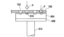
そこで、各プリフォームを落下の途中で各成形面に対してなるべく中心に供給するためのガイド手段が提案されている(上述した特開平11−29333)。図7は、このガイド手段の構造を模式的に示したものである。このガイド手段700は、水平に伸びると共に、漏斗形状の(すなわち上方ほど内径が大きい)貫通孔702を一列に備えたものである。この位置決めアーム700は、下型604の上側に位置し、図示しない搬送装置によって上方から落下供給されたプリフォーム(図中符号Pで示す)を、各貫通孔702によって各成形面616に導くようになっている。このガイド手段700によれば、複数のプリフォームPを、各成形面616から飛び出さないように、各成形面616に導くことができる。
【0006】
【発明が解決しようとする課題】
しかしながら、図7に示した位置決め装置では、プリフォームPの形や表面状態によっては、プリフォームPが貫通孔702中を落下する際に傾いてしまい、プリフォームが成形面616の中心からずれてしまうことがあった。このようにプリフォームが位置ずれしたままプレス成形を行うと、偏肉が生じると共に、面精度も損なわれるという問題がある。
【0007】
一方、特開平9−2825及び特開平5−97448には、成形型(下型)に、各被成形体を把持して位置決めするレバー状の可動部材を多数備えた位置決め機構を取り付けたものが開示されている。しかしながら、このように成形型に位置決め機構を取り付けた構造では、成形型の熱容量が位置決め機構の分だけ大きくなるため、成形型の昇温速度が低下するという問題がある。更に、位置決め機構が成形型と同様に加熱・冷却のサイクルを繰り返し受けると、変形を生じ易く、位置決め精度が低下するという問題もある。
【0008】
又、複数のプリフォームを成形型よりも高温に加熱軟化してから成形型に導入してプレス成形する方法において、一度にプレス成形するプリフォームの成形条件を同じにするためには、複数のプリフォームを成形型に同時に供給し、同時にプレス成形することも必要である。しかしながら、特開平9−2825では、複数のプリフォームを同時に位置修正することは可能であったとしても、複数のプリフォームを同時に成形型に供給し、同時にプレス成形することができるか否かは明らかにされていない。
【0009】
従って本発明の目的は、複数の被成形体をプレス成形して複数個の面精度の良好な光学素子を得ることができる光学素子のプレス成形装置及び光学素子の製造装置及び製造方法を提供することにある。
【0010】
【課題を解決するための手段】
本発明の光学素子のプレス成形装置は、予熱された複数の成形面で、加熱軟化された複数の被成形体を同時にプレス成形することにより複数の光学素子を得る光学素子のプレス成形装置であって、前記複数の成形面は、上型及び下型それぞれの成形面の中心が一列になるよう構成されており、前記被成形体を保持する複数の保持部が一列に配列され、かつ、該複数の保持部の並びに沿って平行に分割することにより、該複数の保持部に保持した複数の被成形体を同時に落下させ、これにより該複数の被成形体を前記複数の成形面に落下供給する落下供給手段と、前記複数の成形面の中心の列に対して対称であって、かつ、互いに平行に開閉する一対の分割体からなり、該分割体の突合せ面側に、前記各被成形体の外周に当接する位置決め面を複数設け、該分割体を閉じる方向に平行移動することにより、前記成形面上に落下供給された複数の被成形体をそれぞれ該成形面の中心に移動させる位置修正手段と、位置修正された前記複数の被成形体を、前記上型及び前記下型により同時にプレス成形するプレス成形手段と、前記位置修正手段を予熱するヒータと、を備え、前記位置修正手段が、前記ヒータにより予熱される位置から前記成形面上に移動し、前記複数の被成形体を位置修正したのち、前記プレス成形に先立ち、前記ヒータにより予熱される位置に退避する構成としてある。
【0011】
ここで、予熱された成形面とは、予熱された成形型の成形面をいう。又、上型は、複数の成形面が形成された一体の上型であっても、上成形型と該上成形型を複数個保持する上母型とからなるものであってもよい。下型も同様である。
【0012】
尚、本発明では、前記加熱軟化された被成形体はガラス材であり、かつ、前記予熱された成形面よりも高い温度で該成形面に落下供給されることが好ましい。この場合、サイクルタイムの短縮、及び成形型の成形面の離型膜の長寿命化の観点から、前記加熱軟化されたガラス材は、109ポアズ未満の粘度まで加熱軟化されることが特に好ましい。
【0013】
更に、本発明では、前記落下供給手段は、前記被成形体を前記保持部においてガスにより浮上させて保持したまま、前記保持部を分割することにより、前記成形面に落下供給することが好ましい。
【0015】
又、本発明の光学素子の製造方法は、予熱した複数の成形面で、該成形面よりも高い温度に加熱軟化した複数の被成形体をプレス成形することにより複数の光学素子を得る光学素子の製造方法であって、加熱軟化された複数の被成形体を、同時に前記複数の成形面に落下供給する工程と、位置修正手段を用いて、落下供給された前記複数の被成形体を、各成形面の中心に移動させることにより位置修正する工程と、位置修正された前記被成形体を前記成形面で同時にプレス成形する工程と、前記位置修正手段を、所定の予熱位置で所定温度に予熱する工程と、を含み、予熱した前記位置修正手段を用いて前記被成形体の位置修正を行ったのち、前記プレス成形工程に先立ち、前記位置修正手段を前記成形面から退避させて前記予熱位置に移動させる方法としてある。
【0016】
尚、本発明では、前記加熱軟化された被成形体はガラス材であり、かつ、前記予熱された成形面よりも高い温度で該成形面に落下供給されることが好ましい。この場合、前記加熱軟化されたガラス材は、109ポアズ未満の粘度まで加熱軟化されることが好ましい。
【0017】
更に、本発明では、前記被成形体が、球形状又は扁平球形状のプリフォームであることが好ましい。
【0019】
【発明の実施の形態】
以下、図示した実施形態に基いて本発明を詳細に説明する。図1は、本発明の一実施の形態に係る被成形体の位置決め装置と共に用いられるプレス成形装置の要部構造を示す断面図である。このプレス成形装置は、ガラス素材を予め扁平な球形状に成形した被成形体としてのプリフォームを用いて、例えば直径17mmの中口径レンズを成形するものである。プレス成形装置は、プリフォームを加圧する上型102及び下型104を有している。上型102及び下型104は、例えばタングステン合金により構成されており、図中左右方向に長い長尺形状を有している。上型102及び下型104の各対向面には、プリフォームに所定の形状を与えるための複数の成形面(後述)が形成されている。上型102及び下型104は、各対向面と反対の側において、支持体106,108を介して上主軸110及び下主軸112に取り付けられている。上主軸110は装置フレーム(図示せず)に固定され、下主軸112は図示しないモータにより鉛直方向に駆動される。すなわち、下主軸112の駆動により、上型102及び下型104の開閉が行われるようになっている。上型102及び下型104の周囲には、これらをそれぞれ高周波誘導加熱する誘導加熱コイル114,116が設けられている。尚、共通の誘導加熱コイルで上型102及び下型104を加熱するようにしても良い。
【0020】
図2は、下型104及びその周囲の誘導加熱コイル116を上方から見た平面形状を示す平面図である。尚、上型102の平面形状は、下型104と同様であるため、図示を省略する。下型104は、互いに平行に延びる一対の長辺104aと、これら長辺104aの両端に位置する一対の半円周状の辺104bとを有している。半円周状の辺104bは、2つの長辺104aの間隔(すなわち、上型102の幅)の1/2と等しい半径を有する半円の円周を構成している。誘導加熱コイル116は、下型104の周囲に、この下型104の外周に倣った形状に巻回されている。
【0021】
下型104の上面には、プリフォームに所望のレンズ形状を付与する6個の成形面A,B,C,D,E,Fが形成されている。これら成形面A〜Fは、下型104の長手方向に沿って一列に配列されている。尚、上型102にも、下型104の成形面A〜Fに対応する位置にそれぞれ成形面が設けられている。以下では、成形面A〜Fを総括して、成形面120と称する。
【0022】
図3(a)は、図1に示したプレス成形装置までプリフォームを搬送する搬送アーム300を示す平面図である。搬送アーム300は、耐熱性の高い金属(例えばステンレス合金)により成形される長尺状部材であり、その長手方向に沿って、プリフォームを保持する6個の保持ブロック304が一列に配列されている。保持ブロック304は、すり鉢状の受け部306を有している。保持ブロック304の材質としては、高密度カーボンの表面をグラッシーカーボンとしたものを用いることができる。図3(b)は、図3(a)におけるIII−III断面図である。図3(b)に示したように、搬送アーム300の内部には、この搬送アーム300の長手方向に延びるガス孔314が形成されており、このガス孔314を介して供給される不活性ガスが受け部306内へ送られ、このガスの圧力により、プリフォームが受け部306内で僅かに浮上されながら搬送されるようになっている。搬送アーム300は、その幅方向の中心線において、2つのアーム片300a,300bに平行に分割されるよう構成されている。搬送アーム300を2つのアーム片300a,300bに分割すると、各保持ブロック304も2つのブロック片304a,304bにそれぞれ分割される。このように搬送アーム300を分割し平行に開くことにより、その保持ブロック304において浮上保持していた、加熱軟化された複数個のプリフォームを下方に同時に落下させることができる。
【0023】
図4は、搬送アーム300が下型104上にプリフォームを落下供給する際、このプリフォームの位置決めを行う位置修正手段である位置決めアーム400の平面形状を示す平面図である。位置決めアーム400は、長尺形状であり、その幅方向における中心線Nを中心として2つのアーム分割体402,404に分割可能な構造を有している。位置決めアーム400は、更に、その長手方向に沿って、プリフォームを位置決めする6個の位置決めブロック410を有している。各位置決めブロック410は、位置決めアーム400の中心線Nにおいて2つの部分412,414に分割可能な構造を有しており、アーム分割体402,404の開閉と共に平行に開閉するようになっている。各位置決めブロック410は、平面視で菱形の開口部416を有しており、その内周面において、プリフォームの外周に接するような形状になっている。位置決めアーム400のアーム分割体402,404は、それぞれの長手方向一端(図中左端)において、一対のスライド体406,408にそれぞれ取り付けられている。このスライド体406,408は、図示しない駆動機構により互いに接近及び離間する方向(図中矢印で示した方向)に移動し、これに伴ってスライド体406,408が互いに平行を保ちつつ開閉するようになっている。すなわち、スライド体406,408が互いに離間する方向に移動すると、アーム分割体402,404が開き、スライド体406,408が互いに接近する方向に移動すると、アーム分割体402,404が閉じるようになっている。
【0024】
この位置決めアーム400は、水平面内において回転可能となっており、図示しない回転機構により、下型104の上方位置と、下型104上から退避した位置(アーム予熱位置)との間で回転するようになっている。位置決めアーム400は、プリフォームの位置決めを行うときには下型104上に位置し、それ以外は、下型104上から退避している。位置決めアーム400の回転角度は、モータパルスやエンコーダ等により検出されており、これに基づいて回転制御がなされている。尚、位置決めアーム400の移動は、回転移動に限らず、水平移動や、水平移動と上下移動との組み合わせ等も可能である。又、位置決めアーム400が下型104上から退避しているときに、この位置決めアーム400を予熱するため、図示しないアーム予熱装置が設けられている。
【0025】
位置決めアーム400の予熱温度は、被成形体であるプリフォームを位置修正する際に、プリフォームに接触してもプリフォームの表面欠陥を招かない温度に設定される。例えば、プリフォームを構成するガラスのTgおよびTsに対して、該予熱温度はTg−200〜Tg+100℃程度であり、好ましくはTg−100〜Ts程度である。
【0026】
又、位置決めアーム400の素材としては、耐熱性が高く、機械的強度に優れ、ガラスとの濡れ性が低いものであることが好ましく、例えば炭素系材料が挙げられる。この場合の炭素系材料としては、高密度カーボン、グラッシーカーボンが好適である。尚、素材としては単一素材である必要はなく、セラミックスや金属の表面に薄膜を成したものでもよい。この場合の薄膜としては、グラファイトカーボン膜、ダイヤモンドライクカーボン膜、ダイヤモンド膜等の炭素系薄膜、貴金属膜が挙げられる。薄膜は、コーティングによるものであってもプレーティングによるものであってもよい。
【0027】
図5は、位置決めアーム400のアーム分割体402,404を開いた状態(a)と閉じた状態(b)を拡大して示すものである。図5において、アーム分割体402,404の各対向面を、突き合わせ面Sとする。アーム分割体402の突き合わせ面S側には、プリフォーム(図5では符号Pで示す)の外周に当接する位置決め面502が形成されており、アーム分割体404の突き合わせ面S側には、プリフォームPの外周に当接する位置決め面504が形成されている。これら位置決め面502,504は、上述した開口部416の端面をなすものである。図5(a)に示したようにアーム分割体402,404が開いているときには、位置決め面502,504は下型104(図1)の成形面上に落下供給されたプリフォームPの外周に対向するようになっている。図5(b)に示したようにアーム分割体402,404を閉じると、位置決め面502,504が各プリフォームPの外周に当接し、これを位置決めする。位置決め面502,504が開閉方向(位置決めアーム400の幅方向)に対してそれぞれ傾斜しているので、各プリフォームPを位置決めアーム400の長手方向及び幅方向に位置決めすることができる。この位置決めにより、プリフォームPの中心と、下型104(図1)の成形面120の中心とが略一致するようになっている。
【0028】
この位置決めアーム400は、作用位置(すなわち、位置決めブロック410が下型104の各成形面120に対応する位置)において、アーム分割体402,404を開いた状態でプリフォームの落下供給を待つよう構成されている。搬送アーム300からプリフォームが落下供給されると、アーム分割体402,404を1回〜数回平行に開閉させ、位置決め面502又は位置決め面504(又は両面)を各プリフォームPの外周に当接させて、複数個のプリフォームPの中心を、下型104の成形面120の中心に同時に略一致させる。
【0029】
プリフォームの位置決めが完了した後は、下型104が下降するか位置決めアーム400が上昇するかして、プリフォームと位置決めアーム400とが接触しない状態として、位置決めアーム400が下型104上から退避する。そののち、プレス成形装置(図1)によるプリフォームのプレス成形が行われる。すなわち、プレス成形装置が、上型102又は下型104(又は両方)を移動させ、これらの成形面においてプリフォームをプレスし、所望のレンズ形状を有するレンズを成形する。
【0030】
次に、本実施の形態に係る成形品の製造方法について説明する。プレス成形装置においては、誘導加熱コイル114,116の高周波誘導加熱により、上型102及び下型104を加熱する。次いで、予め扁平球形状に予備成形されたプリフォームを、搬送アーム300により搬送すると共に、図示しない加熱装置により各プリフォームを加熱する。尚、プリフォームの加熱温度は、上型102及び下型104の温度よりも高く、プリフォームの粘度が109ポアズ未満となる温度であることが好ましい。そののち、搬送アーム300をプレス成形装置の上型102と下型104との間に挿入する。次いで、位置決めアーム400を退避位置から下型104の上方位置まで回転させ、下型104と搬送アーム300との間に位置させる。これにより、位置決めアーム400の各位置決めブロック410が下型104の各成形面120にそれぞれ対応する。そののち、下型104が位置決めアーム400の下面よりも僅かに低い位置まで上昇する。位置決めアーム400は、そのアーム分割体402,404を開いた状態で、搬送アーム300からのプリフォームの落下供給を待つ。搬送アーム300がプリフォームを下型104上に落下供給すると、アーム分割体402,404の各位置決め面502,504が、下型104上の各プリフォームの外周に対向する。位置決めアーム400は、アーム分割体402,404を1回ないし数回閉じることにより、位置決め面502,504をプリフォームの外周に当接させ、これを成形面120の中央に寄せるようにして位置決めする。これにより、プリフォームの中心を、下型104の成形面120の中心に同時に略一致させることができる。プリフォームの位置決めが完了すると、プリフォームが位置決めアーム400よりも下方に位置するよう下型104を下降させ、そののち、位置決めアーム400を退避位置に退避させる。位置決めアーム400が退避したのち、下主軸112を上昇させて上型102と下型104との間で6個のプリフォームを加圧して、所望のレンズ形状を有するレンズを成形する。上型102及び下型104によるプリフォームのプレスが完了すると、下主軸112を下降させ、上型102及び下型104を開放させる。ついで、図示しない取出し装置により、下型104上に残った6個のガラス光学素子を吸着して取り出す。これにより、高精度にプレス成形されたレンズが得られる。
【0031】
以上説明したように、本実施の形態によれば、位置決めアーム400を開閉させ、アーム分割体402,404の各位置決め面502,504を各プリフォームの外周に当接させるようにしたので、プリフォームの傾き等を生じさせること無く、正確に位置決めすることができる。又、位置決めアーム400を下型104上から退避させる構造としたので、位置決め機構を下型に取り付けたものと比較して、下型104の熱容量を小さくすることができ、それだけ下型104の昇温速度及び冷却速度を向上することができる。
【0032】
又、位置決めアーム400を、アーム分割体402,404が開閉する構造としたので、複数のプリフォームを同時に且つ迅速に位置決めすることができる。更に、位置決めアーム400を、別に設けたヒータで予熱するようにしたので、各位置決め面502,504を適切な温度に保つことができる。
【0033】
更に、本実施の形態では、各アーム分割体402,404の突き合わせ面Sを突き合わせた状態で、位置決め面502がプリフォームの外周にちょうど当接してこれを位置決めするようにしたので、単にアーム分割体402,404を閉じるだけで位置決めを行うことができ、従ってアーム分割体402,404の開閉機構を簡単にすることができる。
【0034】
更に、位置決めアーム400と下型104とを接触させない構造としたので、下型104の熱の位置決めアーム400への散逸が殆どなくなり、下型の温度分布を均一に制御することが容易になる。又、位置決めアーム400を退避位置で加熱するアーム予熱装置を設けるようにしたので、位置決めアーム400を予め十分高温にしておくことができ、プリフォームの熱が位置決めアーム400を通じて散逸することを防止できる。加えて、アーム分割体402,404を互いに平行に開閉するようにしたので、各プリフォームを同一の条件で同時に位置決めすることができる。
【0035】
尚、図5(C)に示したように、アーム分割体402,404がその移動ストロークの途中でプリフォームの外周に当接するようにしてもよい。この場合、アーム分割体402,404を、プリフォームの位置決めに最適な位置(例えば位置決め面502,504により形成される開口部416の中心と成形面120の中心とが略一致し、且つ、位置決め面502,504がプリフォームの外周に当接する位置)で停止させることが好ましい。
【0036】
次に、本実施の形態に関する実施例を、以下に説明する。ここでは、プリフォームとして、バリウムホウケイ酸ガラスからなる扁平球状のガラスプリフォームを用いた。上型102及び下型104は、それぞれ、炭化ケイ素(SiC)焼結体からなり成形面にCVD法による炭化ケイ素膜を形成した成形型を5個、タングステン系合金の成形母型で保持する構造により、複数の成形面を有するものとなっている。又、該成形面にはさらに、500Åの厚さのダイヤモンドライクカーボン膜及び/又はi−カーボン膜が形成されている。上型102及び下型104は、同軸上にセットされ、プレス成形の際は、上型102と下型104とこれを互いの同軸を維持するようにガイドする案内型(図示せず)とにより成形型が構成される。上型102と下型104の各々の複数の成形面は、それぞれ一列になるように構成されるとともに、上型成形面と下型成形面の光学中心が一致するように対向して配置されている。上型102及び下型104の加熱は、誘導加熱コイルによって行い、下型104内に挿入した型測温用熱電対にて制御する。このとき、誘導加熱されにくい炭化ケイ素からなる成形型を、誘導加熱されうるタングステン系合金からなる成形母型で保持する上記構造により、誘導加熱された成形母型からの熱伝導により成形型およびその成形面が加熱される。搬送アーム300は、表1に示す流量の98%N2+2%H2ガスの噴出によって、プリフォームを浮上保持するようにした。
【0037】
【表1】

プレス成形装置等が収められた成形室内を真空排気した後、98%N2+2%H2ガスを導入し、同ガス雰囲気としたのち、誘導加熱コイルにより上型102及び下型104を加熱し、型測温用熱電対で測温した上型102及び下型104の温度が、ガラスプリフォームの粘度が1011ポアズに相当する572℃(例1〜3、5)又は1012ポアズに相当する554℃(例4)になるまで加熱し、同温度で保持した。尚、このときは、上型102及び下型104は離間した状態でそれぞれ加熱され、成形の際に前記案内型と共に一体の成形型となる。一方、図示しないプリフォーム加熱装置により、搬送アーム300上のプリフォームの温度を、表1に示すように、ガラスの粘度105.5ポアズに相当する温度である718℃まで加熱保持する。
【0039】
このとき、プリフォームは搬送アーム300上でガスにより浮上しながら加熱軟化する。そして、そのまま、加熱軟化した複数個のプリフォームを浮上保持したアーム300を、下型104の直上まで速やかに移動させ、下型104の成形面120にプリフォームを同時に落下供給する。このとき、下型104の直上には、位置決めアーム400の位置決めブロック410が位置しており、上述したように、落下供給された複数個のプリフォームを下型104の成形面120に対して同時に位置決めする。そののち、位置決めアーム400を下型104上から退避させたのち、プリフォームを10秒間100kg/cm2の圧力にて加圧成形して所定の肉厚とした後、圧力を一気に50kg/cm2とすると同時に、この圧力で保持したガラス成形体及び成形型を、誘導加熱コイルを断電することで放冷して、表1に成形時間(初期加圧時間(10秒間)+2次加圧時間)として示す時間経過秒後に型測温用熱電対で測温した上型102及び下型104の温度が、表1に離型時型温度として示す粘度に相当する温度になったところで、成形型からガラス成形体を離型し取り出した。
【0040】
このようにして得られたガラス成形体(外径φ18mm、肉厚2.9mm、コバ厚1.0mmの両凸レンズ)のアニール後の性能を、干渉計による面精度と、目視外観及び実体顕微鏡による表面状態について評価し、結果を表1に示す。評価は、同一方法で得られた5個のレンズについて行った。表1は、軟化したガラスプリフォームの温度、ガラスプリフォームの形状、アームの浮上皿から流出するガス流量、成形型温度、離型温度を変化させて得られたガラス成形体の評価結果を示す。その結果、何れの成形体(レンズ)も良好なものであった。又、得られた5個のレンズは、いずれも偏肉がなく良好な形状のものであった。
【0041】
以上、本発明の一実施形態を図面に沿って説明した。しかしながら、本発明は前記実施形態に示した事項に限定されず、特許請求の範囲の記載に基いてその変更、改良等が可能であることは明らかである。例えば、位置決めアーム400に設ける位置決めブロックの数は、二以上であれば幾つでもよい。又、各位置決めブロック410の開口部416の形状は、プリフォームを位置決めする作用を奏することができるものであれば、どのような形状であってもよい。
【0042】
【発明の効果】
以上の如く本発明によれば、上型及び下型それぞれの複数の成形面の中心が一列になるよう構成すると共に、前記被成形体を保持する複数の保持部が一列に配列され、かつ、該複数の保持部の並びに沿って平行に分割することにより、該複数の保持部に保持した複数の被成形体を同時に落下させ、これにより該複数の被成形体を前記複数の成形面に落下供給する落下供給手段と、前記複数の成形面の中心の列に対して対称であって、かつ、互いに平行に開閉する一対の分割体からなり、該分割体の突合せ面側に、前記各被成形体の外周に当接する位置決め面を複数設け、該分割体を閉じる方向に平行移動することにより、前記成形面上に落下供給された複数の被成形体をそれぞれ該成形面の中心に移動させる位置修正手段と、位置修正された前記複数の被成形体を、前記上型及び前記下型により同時にプレス成形するプレス成形手段と、を有するようにしたので、複数の被成形体を成形面に同時に供給し、同時に位置修正し、更に同時にプレス成形することができる。つまり、一度にプレス成形する複数の被成形体について、成形条件を同じにすることができる。従って、最適な成形条件を選べば、一度にプレス成形する被成形体を全て面精度のよい光学素子に成形することができる。
特に、本発明にあっては、成形面上で被成形体の位置修正をした位置修正手段を、プレス成形に先立って、ヒータにより予熱される位置に退避させる構成としてあるので、位置決め機構を成形型に取り付けたものと比較して、成形型の熱容量を小さくすることができ、それだけ成形型の昇温速度及び冷却速度を向上することができる。
これに加えて、本発明では、位置修正手段を、別に設けたヒータで予熱するようにしたので、各位置決め面を適切な温度に保つことができる。また、位置修正手段を退避位置で加熱するヒータを設けるようにしたので、位置修正手段を予め十分高温にしておくことができ、被成形体の熱が位置修正手段を通じて散逸することを防止できる。
【0043】
又、加熱軟化したガラスプリフォームを、これよりも低い温度に予熱された成形型の成形面に供給したのちプレス成形する方法の場合には、該ガラスプリフォームは成形型と接触したときから接触部分について冷却が始まるため、同時に成形面に供給され、同時に位置修正され、同時にプレス成形される本発明により、各ガラスプリフォームについて成形条件を同じにできる効果がより一層奏される。更に、ガラスプリフォームの成形面への供給からプレス成形が開始されるまでに要する時間が短いため、面精度の向上にも寄与する。
【0044】
加えて、ガラスプリフォームが変形しやすい粘度、例えば109ポアズ未満になるまで加熱軟化したガラスプリフォームを成形面に供給する際、ガラスプリフォームの表面欠陥を防止するために浮上させながら保持した状態から落下供給することによりガラスプリフォームの供給位置をコントロールしにくい場合でも、本発明によれば、複数のガラスプリフォームが同時にかつ正確に位置修正されるので、偏肉もなく、上記効果が奏される。
【0045】
更に、ガラスプリフォームとして、成形面に供給されたのちに自ら成形面中央に転がるような形状(例えば球形状)ではない形状(例えば扁平球形状)のものを用いた場合や、成形面上でガラスがへたって変形するような粘性(例えば109ポアズ未満)に加熱軟化されている場合にも、該複数のガラスプリフォームが同時にかつ正確に位置修正されるので、偏肉もなく、上記効果が奏される。
【0046】
又、複数の被成形体を、落下供給手段の保持部上で一列に保持するようにしたので、単に保持部を平行に分割するだけで、これら複数の被成形体を同時に落下供給することができる。そのため、複数の被成形体を同時供給する際に通常用いられる吸着パッドが不要になる。従って、被成形体が109ポアズ未満の低粘度になるまで加熱軟化されたガラスプリフォームであっても、被成形体に(吸着パッドとの接触により生じるような)表面欠陥が発生することが防止される。
【図面の簡単な説明】
【図1】本発明の一実施の形態に係る位置決め装置と共に使用されるプレス成形装置の要部構造を示す断面図である。
【図2】図1に示したプレス成形装置の下型の平面形状を示す平面図である。
【図3】図1に示したプレス成形装置にプリフォームを供給するための搬送アームの平面図(a)及び断面図(b)である。
【図4】図1に示したプレス成形装置の下型に対してプリフォームの位置決めを行う位置決めアームの平面形状を示す正面図である。
【図5】図4に示した位置決めアームを拡大して示す図である。
【図6】従来のプレス成形装置の基本構成を示す図である。
【図7】従来の被成形体の位置決め装置の基本構成を示す図である。
【符号の説明】
102 上型
104 下型
110 上主軸
112 下主軸
114,116 誘導加熱コイル
120 成形面
300 搬送アーム
400 位置決めアーム
402,404 アーム分割体
406,408 スライド体
410 位置決めブロック
416 開口部
502,504 位置決め面[0001]
BACKGROUND OF THE INVENTION
The present invention relates to an optical element press molding apparatus, an optical element manufacturing apparatus, and a manufacturing method for obtaining an optical element having a predetermined shape by heat-softening a preformed glass material and then press molding.
[0002]
[Prior art]
In recent years, in the field of manufacturing optical lenses and the like, in order to obtain a highly accurate lens shape without performing surface polishing, a preform in which a glass material is preformed in a predetermined shape is prepared, and the preform is heated and softened. After that, a method of pressing using a mold having a highly accurate press surface has been proposed (Japanese Patent Laid-Open No. 2001-10829, etc.).
[0003]
FIG. 6 shows a basic configuration of a press forming apparatus used for this kind of press working. The press molding apparatus shown in FIG. 6 presses a plurality of (for example, four) preforms at a time using an
[0004]
Thus, in a method of manufacturing a plurality of optical elements by press-molding a plurality of preforms with a plurality of molds, a method is disclosed in which a plurality of preforms are simultaneously dropped and supplied onto a plurality of molding surfaces of the mold. (JP-A-11-29333). However, when a plurality of preforms are dropped and supplied to the molding surface, the preforms are not supplied to the center of the molding surface, and there is a problem that uneven thickness occurs when press molding is performed as it is.
[0005]
Therefore, a guide means for supplying each preform to the center of each molding surface as much as possible in the middle of dropping has been proposed (JP-A-11-29333 described above). FIG. 7 schematically shows the structure of the guide means. This guide means 700 is provided with a row of through-
[0006]
[Problems to be solved by the invention]
However, in the positioning device shown in FIG. 7, depending on the shape and surface state of the preform P, the preform P is inclined when it falls in the
[0007]
On the other hand, in Japanese Patent Laid-Open Nos. 9-2825 and 5-97448, a positioning mechanism provided with a large number of lever-like movable members for gripping and positioning each molding object is attached to a molding die (lower die). It is disclosed. However, in the structure in which the positioning mechanism is attached to the molding die in this way, the heat capacity of the molding die increases by the amount of the positioning mechanism. Further, when the positioning mechanism is repeatedly subjected to a heating / cooling cycle in the same manner as the mold, there is a problem that the positioning mechanism is likely to be deformed and the positioning accuracy is lowered.
[0008]
In addition, in the method of heat-softening a plurality of preforms to a temperature higher than that of the mold and then introducing into the mold and press-molding, in order to make the molding conditions of the preforms that are press-molded at the same time, It is also necessary to supply the preform to the mold simultaneously and press-mold simultaneously. However, in Japanese Patent Laid-Open No. 9-2825, even if it is possible to simultaneously correct the position of a plurality of preforms, whether or not a plurality of preforms can be simultaneously supplied to a mold and simultaneously press-molded is determined. It has not been revealed.
[0009]
Accordingly, an object of the present invention is to provide an optical element press molding apparatus, an optical element manufacturing apparatus, and a manufacturing method capable of obtaining a plurality of optical elements with good surface accuracy by press molding a plurality of molded objects. There is.
[0010]
[Means for Solving the Problems]
The present inventionOptical element press molding equipmentIs a press molding apparatus of an optical element that obtains a plurality of optical elements by simultaneously press-molding a plurality of heat-softened moldings with a plurality of preheated molding surfaces, wherein the plurality of molding surfaces are: The center of the molding surface of each of the upper mold and the lower mold is arranged in a line, a plurality of holding parts for holding the molded body are arranged in a line, and parallel along the arrangement of the plurality of holding parts. A plurality of objects to be molded held in the plurality of holding portions at the same time, thereby dropping the plurality of objects to be molded onto the plurality of molding surfaces; A positioning surface that is symmetric with respect to the center row of the molding surfaces and that opens and closes in parallel with each other, and that is in contact with the outer periphery of each of the molded bodies on the butt surface side of the division bodies. In the direction to close the divided body A plurality of workpieces dropped onto the molding surface and moved to the center of the molding surface by moving in a row, and the plurality of workpieces whose positions have been corrected, And press molding means for press molding simultaneously with the lower mold;A heater for preheating the position correcting means, and the position correcting means moves from the position preheated by the heater onto the molding surface to correct the positions of the plurality of molded objects, and then presses the press. Prior to molding, the heater is retracted to a position preheated by the heater..
[0011]
Here, the preheated molding surface means the molding surface of a preheated mold. The upper mold may be an integral upper mold in which a plurality of molding surfaces are formed, or may be composed of an upper mold and an upper mother mold that holds a plurality of the upper molds. The same applies to the lower mold.
[0012]
In the present invention, it is preferable that the heat-softened molded object is a glass material and is dropped and supplied to the molding surface at a temperature higher than the preheated molding surface. In this case, from the viewpoint of shortening the cycle time and extending the life of the release film on the molding surface of the mold, the heat-softened glass material is 109It is particularly preferred to heat soften to a viscosity of less than Poise.
[0013]
Furthermore, in the present invention, it is preferable that the drop supply means drop-feeds the molding surface by dividing the holding portion while the molded body is floated and held by gas in the holding portion.
[0015]
In addition, the manufacturing method of the optical element of the present invention isAn optical element manufacturing method for obtaining a plurality of optical elements by press-molding a plurality of molded bodies heated and softened at a temperature higher than the molding surface with a plurality of preheated molding surfaces, A step of dropping and supplying a plurality of objects to be molded to the plurality of molding surfaces simultaneously;Using position correction means,Fall suppliedThe plurality ofA step of correcting the position of the molded body by moving it to the center of each molding surface; and a step of simultaneously press-molding the molded body whose position has been corrected on the molding surface;And a step of preheating the position correction means to a predetermined temperature at a predetermined preheating position, and after correcting the position of the molded body using the preheated position correction means, prior to the press molding step. The position correcting means is retracted from the molding surface and moved to the preheating position.
[0016]
In the present invention, it is preferable that the heat-softened molded object is a glass material and is dropped and supplied to the molding surface at a temperature higher than the preheated molding surface. In this case, the heat-softened glass material is 109It is preferably heat-softened to a viscosity of less than Poise.
[0017]
Furthermore, in the present invention, it is preferable that the object to be molded is a preform having a spherical shape or a flat spherical shape.
[0019]
DETAILED DESCRIPTION OF THE INVENTION
Hereinafter, the present invention will be described in detail based on the illustrated embodiments. FIG. 1 is a cross-sectional view showing the main structure of a press molding apparatus used together with a molding body positioning apparatus according to an embodiment of the present invention. This press molding apparatus is for molding a medium-diameter lens having a diameter of 17 mm, for example, using a preform as a molded body in which a glass material is previously molded into a flat spherical shape. The press molding apparatus has an
[0020]
FIG. 2 is a plan view showing a planar shape of the
[0021]
On the upper surface of the
[0022]
FIG. 3A is a plan view showing a
[0023]
FIG. 4 is a plan view showing a planar shape of a
[0024]
The
[0025]
The preheating temperature of the
[0026]
In addition, the material of the
[0027]
FIG. 5 shows an enlarged view (a) and a closed state (b) of the arm divided
[0028]
The
[0029]
After the positioning of the preform is completed, the
[0030]
Next, a method for manufacturing a molded product according to the present embodiment will be described. In the press molding apparatus, the
[0031]
As described above, according to the present embodiment, the
[0032]
Further, since the
[0033]
Further, in the present embodiment, the
[0034]
Further, since the
[0035]
As shown in FIG. 5C, the arm divided
[0036]
Next, examples relating to the present embodiment will be described below. Here, a flat spherical glass preform made of barium borosilicate glass was used as the preform. Each of the
[0037]
[Table 1]
98% N after evacuating the molding chamber containing the press molding equipment2+ 2% H2After introducing the gas and making the same gas atmosphere, the
[0039]
At this time, the preform is heated and softened while floating on the
[0040]
The performance of the glass molded body thus obtained (biconvex lens having an outer diameter of φ18 mm, a wall thickness of 2.9 mm, and an edge thickness of 1.0 mm) after annealing was measured with respect to the surface accuracy by the interferometer, the visual appearance and the stereomicroscope. The surface condition was evaluated and the results are shown in Table 1. Evaluation was performed on five lenses obtained by the same method. Table 1 shows the evaluation results of the glass moldings obtained by changing the temperature of the softened glass preform, the shape of the glass preform, the flow rate of the gas flowing out from the levitation pan of the arm, the molding die temperature, and the mold release temperature. . As a result, all the molded bodies (lenses) were good. In addition, all of the obtained five lenses had a good shape without uneven thickness.
[0041]
The embodiment of the present invention has been described with reference to the drawings. However, the present invention is not limited to the matters shown in the above-described embodiments, and it is obvious that changes, improvements, and the like can be made based on the description of the scope of claims. For example, the number of positioning blocks provided in the
[0042]
【The invention's effect】
As described above, according to the present invention, the center of the plurality of molding surfaces of each of the upper mold and the lower mold is configured in a row, and the plurality of holding portions that hold the molding target are arranged in a row, and By dividing in parallel along the arrangement of the plurality of holding portions, the plurality of moldings held by the plurality of holding portions are simultaneously dropped, and thereby the plurality of moldings are dropped on the plurality of molding surfaces. A drop supply means for supplying and a pair of divided bodies that are symmetrical with respect to the central row of the plurality of molding surfaces and open and close in parallel with each other. A plurality of positioning surfaces abutting on the outer periphery of the molded body are provided, and the plurality of molded bodies dropped and supplied onto the molding surface are moved to the center of the molding surface by parallel movement in the closing direction of the divided bodies. Position correction means and position correction A plurality of objects to be molded, and press forming means for simultaneously press-molding with the upper mold and the lower mold, so that the plurality of objects to be molded are simultaneously supplied to the molding surface, and the position is simultaneously corrected. Furthermore, press molding can be performed simultaneously. That is, the molding conditions can be made the same for a plurality of molded objects that are press-molded at a time. Therefore, if the optimum molding conditions are selected, it is possible to mold all the objects to be molded that are press-molded at a time into optical elements with good surface accuracy.
In particular, in the present invention, since the position correcting means for correcting the position of the molded object on the molding surface is retracted to a position preheated by a heater prior to press molding, the positioning mechanism is molded. Compared with what was attached to the type | mold, the heat capacity of a shaping | molding die can be made small, and the temperature increase rate and cooling rate of a shaping | molding die can be improved so much.
In addition, in the present invention, since the position correcting means is preheated by a separately provided heater, each positioning surface can be maintained at an appropriate temperature. In addition, since the heater for heating the position correction means at the retracted position is provided, the position correction means can be set to a sufficiently high temperature in advance, and the heat of the molded body can be prevented from being dissipated through the position correction means.
[0043]
In the case of the method of press molding after supplying the heat-softened glass preform to the molding surface of the mold preheated to a temperature lower than this, the glass preform is contacted from when it comes into contact with the mold. Since cooling starts for the portions, the present invention in which the glass preforms are simultaneously supplied to the molding surface, simultaneously corrected in position, and press-molded at the same time has the effect of making the molding conditions the same for each glass preform. Furthermore, since the time required from the supply of the glass preform to the molding surface to the start of press molding is short, it contributes to the improvement of surface accuracy.
[0044]
In addition, the viscosity at which the glass preform is easily deformed, for example 109When supplying a glass preform heated and softened to less than poise to the molding surface, the supply position of the glass preform is controlled by dropping it from the state of holding it while floating to prevent surface defects of the glass preform. Even if it is difficult to do so, according to the present invention, the position of the plurality of glass preforms is corrected simultaneously and accurately, so that the above effect can be obtained without uneven thickness.
[0045]
Furthermore, when a glass preform having a shape (for example, a flat spherical shape) that is not a shape (for example, a spherical shape) that is supplied to the molding surface and then rolls to the center of the molding surface is used. Viscosity (eg 109Even when the glass preform is heat-softened to less than (poise), since the positions of the plurality of glass preforms are simultaneously and accurately corrected, there is no uneven thickness, and the above-described effect is exhibited.
[0046]
In addition, since the plurality of objects to be molded are held in a row on the holding part of the drop supply means, the plurality of objects to be molded can be dropped and supplied simultaneously by simply dividing the holding part in parallel. it can. Therefore, the suction pad normally used when supplying a several to-be-molded body simultaneously becomes unnecessary. Therefore, the object to be molded is 109Even if the glass preform is heated and softened until the viscosity becomes lower than the poise, it is possible to prevent surface defects (such as those caused by contact with the suction pad) from occurring on the molded body.
[Brief description of the drawings]
FIG. 1 is a cross-sectional view showing the main structure of a press molding apparatus used with a positioning apparatus according to an embodiment of the present invention.
2 is a plan view showing a planar shape of a lower mold of the press molding apparatus shown in FIG. 1. FIG.
3 is a plan view (a) and a cross-sectional view (b) of a transfer arm for supplying a preform to the press molding apparatus shown in FIG. 1; FIG.
4 is a front view showing a planar shape of a positioning arm for positioning a preform with respect to a lower mold of the press molding apparatus shown in FIG. 1. FIG.
5 is an enlarged view of the positioning arm shown in FIG. 4. FIG.
FIG. 6 is a diagram showing a basic configuration of a conventional press forming apparatus.
FIG. 7 is a diagram showing a basic configuration of a conventional positioning apparatus for a molded object.
[Explanation of symbols]
102 Upper mold
104 Lower mold
110 Upper spindle
112 Lower spindle
114, 116 induction heating coil
120 Molding surface
300 Transfer arm
400 Positioning arm
402,404 Arm divided body
406,408 Slide body
410 Positioning block
416 opening
502,504 Positioning surface
Claims (8)
前記複数の成形面は、上型及び下型それぞれの成形面の中心が一列になるよう構成されており、
前記被成形体を保持する複数の保持部が一列に配列され、かつ、該複数の保持部の並びに沿って平行に分割することにより、該複数の保持部に保持した複数の被成形体を同時に落下させ、これにより該複数の被成形体を前記複数の成形面に落下供給する落下供給手段と、
前記複数の成形面の中心の列に対して対称であって、かつ、互いに平行に開閉する一対の分割体からなり、該分割体の突合せ面側に、前記各被成形体の外周に当接する位置決め面を複数設け、該分割体を閉じる方向に平行移動することにより、前記成形面上に落下供給された複数の被成形体をそれぞれ該成形面の中心に移動させる位置修正手段と、
位置修正された前記複数の被成形体を、前記上型及び前記下型により同時にプレス成形するプレス成形手段と、
前記位置修正手段を予熱するヒータと、
を備え、
前記位置修正手段が、前記ヒータにより予熱される位置から前記成形面上に移動し、前記複数の被成形体を位置修正したのち、前記プレス成形に先立ち、前記ヒータにより予熱される位置に退避することを特徴とする光学素子のプレス成形装置。An optical element press molding apparatus for obtaining a plurality of optical elements by simultaneously press molding a plurality of heat-softened moldings on a plurality of preheated molding surfaces,
The plurality of molding surfaces are configured such that the center of the molding surface of each of the upper mold and the lower mold is in a line,
A plurality of holding parts for holding the molded body are arranged in a line and divided in parallel along the arrangement of the plurality of holding parts, so that the plurality of molded bodies held in the plurality of holding parts can be simultaneously Drop supply means for dropping and thereby supplying the plurality of moldings to the plurality of molding surfaces;
It consists of a pair of divided bodies that are symmetrical with respect to the center row of the plurality of molding surfaces and open and close in parallel to each other, and abut the surface of the divided bodies against the outer circumferences of the respective molding bodies A plurality of positioning surfaces, and by parallel translation in the direction of closing the divided body, a position correcting means for moving the plurality of moldings dropped and supplied onto the molding surface respectively to the center of the molding surface;
Press molding means for simultaneously press-molding the plurality of moldings whose positions have been corrected by the upper mold and the lower mold ;
A heater for preheating the position correcting means;
With
The position correcting means moves from the position preheated by the heater onto the molding surface, corrects the positions of the plurality of objects to be molded, and then retracts to a position preheated by the heater prior to the press molding. An optical element press molding apparatus.
加熱軟化された複数の被成形体を、同時に、前記複数の成形面に落下供給する工程と、
位置修正手段を用いて、落下供給された前記複数の被成形体を、各成形面の中心に移動させることにより位置修正する工程と、
位置修正された前記複数の被成形体を前記成形面で同時にプレス成形する工程と、
前記位置修正手段を、所定の予熱位置で所定温度に予熱する工程と、
を含み、
予熱した前記位置修正手段を用いて前記複数の被成形体の位置修正を行ったのち、前記プレス成形工程に先立ち、前記位置修正手段を前記成形面から退避させて前記予熱位置に移動させることを特徴とする光学素子の製造方法。A method for producing an optical element by obtaining a plurality of optical elements by press-molding a plurality of molded bodies heated and softened at a temperature higher than the molding surface with a plurality of preheated molding surfaces,
A step of supplying a plurality of moldings softened by heating to the plurality of molding surfaces at the same time;
A step of correcting the position by moving the plurality of moldings supplied to be dropped to the center of each molding surface using a position correcting means ;
A step of simultaneously press-molding the plurality of moldings whose positions have been corrected on the molding surface ;
Preheating the position correcting means to a predetermined temperature at a predetermined preheating position;
Including
After performing the position correction of the plurality of moldings using the preheated position correction means, prior to the press molding step, the position correction means is retracted from the molding surface and moved to the preheating position. A method for manufacturing an optical element.
Priority Applications (2)
| Application Number | Priority Date | Filing Date | Title |
|---|---|---|---|
| JP2001300638A JP3869239B2 (en) | 2001-09-28 | 2001-09-28 | Optical element press molding apparatus and optical element manufacturing method |
| US10/254,855 US7121119B2 (en) | 2001-09-28 | 2002-09-26 | Press molding apparatus for an optical element and method of manufacturing the optical element |
Applications Claiming Priority (1)
| Application Number | Priority Date | Filing Date | Title |
|---|---|---|---|
| JP2001300638A JP3869239B2 (en) | 2001-09-28 | 2001-09-28 | Optical element press molding apparatus and optical element manufacturing method |
Publications (2)
| Publication Number | Publication Date |
|---|---|
| JP2003104741A JP2003104741A (en) | 2003-04-09 |
| JP3869239B2 true JP3869239B2 (en) | 2007-01-17 |
Family
ID=19121177
Family Applications (1)
| Application Number | Title | Priority Date | Filing Date |
|---|---|---|---|
| JP2001300638A Expired - Lifetime JP3869239B2 (en) | 2001-09-28 | 2001-09-28 | Optical element press molding apparatus and optical element manufacturing method |
Country Status (2)
| Country | Link |
|---|---|
| US (1) | US7121119B2 (en) |
| JP (1) | JP3869239B2 (en) |
Families Citing this family (8)
| Publication number | Priority date | Publication date | Assignee | Title |
|---|---|---|---|---|
| US7013676B2 (en) * | 2001-08-10 | 2006-03-21 | Hoya Corporation | Press molding apparatus |
| JP4758771B2 (en) * | 2006-01-19 | 2011-08-31 | 富士フイルム株式会社 | Mold for molding |
| JP4124239B2 (en) * | 2006-04-25 | 2008-07-23 | ソニー株式会社 | Optical element molding apparatus and molding method |
| US8141384B2 (en) * | 2006-05-03 | 2012-03-27 | 3M Innovative Properties Company | Methods of making LED extractor arrays |
| US8931308B2 (en) * | 2011-02-10 | 2015-01-13 | Hoya Corporation | Method of producing glass blank for substrate of information recording medium, substrate for information recording medium, and information recording medium; and manufacturing apparatus for glass blank for substrate of information recording medium |
| JP6385662B2 (en) * | 2012-12-28 | 2018-09-05 | 日本電気硝子株式会社 | Manufacturing method of glass material |
| CN113480148B (en) * | 2021-07-22 | 2022-06-17 | 重庆市机电设计研究院 | Large optical glass press |
| CN115286216B (en) * | 2022-08-15 | 2023-08-29 | 安徽胜利精密制造科技有限公司 | Mould equipment is used in glass production that can drawing of patterns fast |
Family Cites Families (12)
| Publication number | Priority date | Publication date | Assignee | Title |
|---|---|---|---|---|
| US4065286A (en) * | 1967-04-01 | 1977-12-27 | Hermann Heye | Machine for the production of containers or the like of vitreous material |
| US4580964A (en) * | 1984-07-26 | 1986-04-08 | Microdot Inc. | Press loading apparatus |
| JP2636083B2 (en) | 1990-12-21 | 1997-07-30 | キヤノン株式会社 | Optical element molding method |
| JP2986647B2 (en) * | 1993-05-31 | 1999-12-06 | キヤノン株式会社 | Method for manufacturing optical glass element |
| JPH08259242A (en) * | 1995-03-24 | 1996-10-08 | Hooya Precision Kk | Flotation softening method for glass material, manufacture of optical device and optical device |
| JP3501580B2 (en) | 1995-04-20 | 2004-03-02 | キヤノン株式会社 | Optical element molding method and molding apparatus |
| US5762673A (en) * | 1997-01-24 | 1998-06-09 | Hoya Precision Inc. | Method of manufacturing glass optical elements |
| JP3608768B2 (en) | 1997-05-13 | 2005-01-12 | Hoya株式会社 | Glass optical element press molding apparatus and glass optical element molding method |
| US6141991A (en) * | 1997-05-13 | 2000-11-07 | Hoya Corporation | Press molding apparatus for glass optical elements and molding method for glass optical elements |
| US6370915B1 (en) * | 1997-05-20 | 2002-04-16 | Hoya Corporation | Method for supplying glass molding material to molds, and method for manufacturing glass optical elements |
| US6098427A (en) * | 1998-10-29 | 2000-08-08 | Owens-Brockway Glass Container Inc. | Neck ring mechanism for glass forming machine |
| JP3890167B2 (en) | 1999-06-24 | 2007-03-07 | Hoya株式会社 | Glass press molding apparatus, method of operating the same, and optical lens molding method |
-
2001
- 2001-09-28 JP JP2001300638A patent/JP3869239B2/en not_active Expired - Lifetime
-
2002
- 2002-09-26 US US10/254,855 patent/US7121119B2/en not_active Expired - Lifetime
Also Published As
| Publication number | Publication date |
|---|---|
| US7121119B2 (en) | 2006-10-17 |
| JP2003104741A (en) | 2003-04-09 |
| US20030066312A1 (en) | 2003-04-10 |
Similar Documents
| Publication | Publication Date | Title |
|---|---|---|
| US5588980A (en) | Apparatus for molding a glass optical element with a transporting supporting member | |
| US20060090512A1 (en) | Press molding apparatus and method of producing a glass optical element using the apparatus | |
| US6141991A (en) | Press molding apparatus for glass optical elements and molding method for glass optical elements | |
| JP3869239B2 (en) | Optical element press molding apparatus and optical element manufacturing method | |
| JP5021196B2 (en) | Mold press mold, optical element manufacturing method, and concave meniscus lens | |
| JP5021205B2 (en) | Mold press mold and optical element manufacturing method | |
| JP3608768B2 (en) | Glass optical element press molding apparatus and glass optical element molding method | |
| JP3188676B2 (en) | Method for manufacturing glass molded body | |
| JP4266115B2 (en) | Mold press molding apparatus and glass optical element manufacturing method | |
| JP3869231B2 (en) | Press molding apparatus and optical element manufacturing method | |
| JP4141983B2 (en) | Mold press molding method and optical element manufacturing method | |
| JP2003063834A (en) | Press molding apparatus and method for manufacturing optical element | |
| JP2005001917A (en) | Mold press-forming apparatus and method of manufacturing optical device | |
| JP4157080B2 (en) | Mold press molding apparatus and optical element manufacturing method | |
| JP2005281053A (en) | Forming apparatus for mold press, method of manufacturing optical device, and optical device | |
| JP4327974B2 (en) | Method for forming optical glass element | |
| JP3767780B2 (en) | Manufacturing method of glass optical element | |
| JP3753415B2 (en) | Glass optical element molding method | |
| JP4792141B2 (en) | Mold press mold and optical element manufacturing method | |
| JPH08169722A (en) | Method and device for forming glass optical element | |
| JP4094587B2 (en) | Glass optical element molding method | |
| JP2004010404A (en) | Process for manufacturing glass optical element | |
| JP2007112010A (en) | Method and apparatus for molding thermoplastic material | |
| JPH0648749A (en) | Production of ring-shaped lens and device therefor | |
| JP2012066989A (en) | Molding unit for optical element and method of molding |
Legal Events
| Date | Code | Title | Description |
|---|---|---|---|
| A977 | Report on retrieval |
Free format text: JAPANESE INTERMEDIATE CODE: A971007 Effective date: 20050901 |
|
| A131 | Notification of reasons for refusal |
Free format text: JAPANESE INTERMEDIATE CODE: A131 Effective date: 20060620 |
|
| A521 | Request for written amendment filed |
Free format text: JAPANESE INTERMEDIATE CODE: A523 Effective date: 20060821 |
|
| TRDD | Decision of grant or rejection written | ||
| A01 | Written decision to grant a patent or to grant a registration (utility model) |
Free format text: JAPANESE INTERMEDIATE CODE: A01 Effective date: 20060926 |
|
| A61 | First payment of annual fees (during grant procedure) |
Free format text: JAPANESE INTERMEDIATE CODE: A61 Effective date: 20061012 |
|
| R150 | Certificate of patent or registration of utility model |
Ref document number: 3869239 Country of ref document: JP Free format text: JAPANESE INTERMEDIATE CODE: R150 Free format text: JAPANESE INTERMEDIATE CODE: R150 |
|
| FPAY | Renewal fee payment (event date is renewal date of database) |
Free format text: PAYMENT UNTIL: 20101020 Year of fee payment: 4 |
|
| FPAY | Renewal fee payment (event date is renewal date of database) |
Free format text: PAYMENT UNTIL: 20101020 Year of fee payment: 4 |
|
| FPAY | Renewal fee payment (event date is renewal date of database) |
Free format text: PAYMENT UNTIL: 20111020 Year of fee payment: 5 |
|
| FPAY | Renewal fee payment (event date is renewal date of database) |
Free format text: PAYMENT UNTIL: 20111020 Year of fee payment: 5 |
|
| FPAY | Renewal fee payment (event date is renewal date of database) |
Free format text: PAYMENT UNTIL: 20121020 Year of fee payment: 6 |
|
| FPAY | Renewal fee payment (event date is renewal date of database) |
Free format text: PAYMENT UNTIL: 20121020 Year of fee payment: 6 |
|
| FPAY | Renewal fee payment (event date is renewal date of database) |
Free format text: PAYMENT UNTIL: 20131020 Year of fee payment: 7 |
|
| R250 | Receipt of annual fees |
Free format text: JAPANESE INTERMEDIATE CODE: R250 |
|
| R250 | Receipt of annual fees |
Free format text: JAPANESE INTERMEDIATE CODE: R250 |
|
| R250 | Receipt of annual fees |
Free format text: JAPANESE INTERMEDIATE CODE: R250 |
|
| R250 | Receipt of annual fees |
Free format text: JAPANESE INTERMEDIATE CODE: R250 |
|
| R250 | Receipt of annual fees |
Free format text: JAPANESE INTERMEDIATE CODE: R250 |
|
| R250 | Receipt of annual fees |
Free format text: JAPANESE INTERMEDIATE CODE: R250 |