JP4785778B2 - Imaging device, control method thereof, and program - Google Patents
Imaging device, control method thereof, and program Download PDFInfo
- Publication number
- JP4785778B2 JP4785778B2 JP2007076766A JP2007076766A JP4785778B2 JP 4785778 B2 JP4785778 B2 JP 4785778B2 JP 2007076766 A JP2007076766 A JP 2007076766A JP 2007076766 A JP2007076766 A JP 2007076766A JP 4785778 B2 JP4785778 B2 JP 4785778B2
- Authority
- JP
- Japan
- Prior art keywords
- recording medium
- recording
- data
- additional information
- imaging
- Prior art date
- Legal status (The legal status is an assumption and is not a legal conclusion. Google has not performed a legal analysis and makes no representation as to the accuracy of the status listed.)
- Expired - Fee Related
Links
Images


Description
本発明は、異なる種類のメモリカード等の記録媒体に画像データを記録可能な撮像装置、その制御方法、及びプログラムに関する。 The present invention relates to an imaging apparatus capable of recording image data on recording media such as different types of memory cards, a control method thereof, and a program.
従来より撮影画像をデジタル信号として記録再生するデジタルカメラが知られている。この種のデジタルカメラでは、記録媒体として再書き込み可能なフラッシュメモリをカード型にパッケージ化したメモリカードが用いられる。この場合、撮影後にユーザが気に入らない画像データを消去したり、記録媒体内の全ての画像データを消去したりすることができる(特許文献1等を参照)。 Conventionally, a digital camera that records and reproduces a captured image as a digital signal is known. In this type of digital camera, a memory card in which a rewritable flash memory is packaged in a card type is used as a recording medium. In this case, image data that the user does not like after shooting can be deleted, or all image data in the recording medium can be deleted (see Patent Document 1 and the like).
近年では、メモリカードの価格は低下してきているとはいえ、大容量のものになるとまだ高価である。 In recent years, although the price of a memory card has been decreasing, it is still expensive when it has a large capacity.
そこで、同一のアドレスに対してデータの再書き込みを不可能とすることで、コスト低下を図ったメモリカードが検討されている。このようにデータの書き込みを一度限りとすることで、書き込みの繰り返しに対する動作保障が不要となり、製造原価が安く、また、製品に対する評価コストも小さくすることが可能となる。 In view of this, a memory card is being studied in which cost reduction is achieved by making it impossible to rewrite data to the same address. In this way, by writing data only once, it is not necessary to guarantee the operation against repeated writing, the manufacturing cost is low, and the evaluation cost for the product can be reduced.
今後は、従来方式のデジタルカメラに対して、上述した同一のアドレスに対してデータの再書き込みを不可能としたメモリカードを装着して使用する状況も考えられる。しかしながら、その場合に、例えば日時設定が不正な状態で撮影すると、撮影日時が不正なファイルとなってしまい、記録容量を無駄に消費することになる。 In the future, it is conceivable to use a conventional digital camera with a memory card that cannot rewrite data to the same address as described above. However, in this case, for example, if shooting is performed in a state where the date and time setting is incorrect, the shooting date and time become an incorrect file, and the recording capacity is wasted.
本発明は、上記のような点に鑑みてなされたものであり、再書き込み不可能な記録媒体を装着したときに、無駄な記録容量の消費を防ぎ、該記録媒体を有効に使用できるようにすることを目的とする。 The present invention has been made in view of the above-described points, so that when a non-rewritable recording medium is loaded, useless recording capacity is prevented and the recording medium can be used effectively. The purpose is to do.
本発明の撮像装置は、記録媒体が着脱可能に装着される撮像装置であって、撮像手段と、前記撮像手段により得られた画像データ及び前記画像データに関する付加情報を前記記録媒体に記録するデータ記録手段と、前記記録媒体として、同一のアドレスに対してデータの再書き込みが可能な第1の記録媒体、及び、同一のアドレスに対してデータの再書き込みが不可能な第2の記録媒体のいずれが装着されているかを判定する判定手段と、前記判定手段による判別結果により前記第1の記録媒体が装着されていると判定された場合と、前記第2の記録媒体が装着されていると判定された場合とで、前記付加情報の設定がなされていない状態での前記撮像手段又は前記データ記録手段に関する動作を異ならしめる制御手段とを備えたことを特徴とする。 An imaging apparatus according to the present invention is an imaging apparatus in which a recording medium is detachably mounted, and is an imaging unit, image data obtained by the imaging unit, and data for recording additional information related to the image data on the recording medium a recording unit, as the recording medium, the first recording medium capable of rewriting data for the same address, and, the same address second incapable of rewriting data to the recording medium Determining means for determining which is mounted, a case where it is determined that the first recording medium is mounted based on a determination result by the determining means, and a case where the second recording medium is mounted in the case where it is determined, characterized in that a control unit made different operations relating to the image pickup means or said data recording means in a state in which setting of the additional information is not made To.
本発明によれば、データの再書き込み可能/不可能な2種類の記録媒体を使用可能な撮像装置において、特に再書き込み不可能な記録媒体を装着したときに、無駄な記録容量の消費を防ぎ、該記録媒体を有効に使用することができる。 According to the present invention, in an imaging apparatus capable of using two types of recording media in which data is rewritable / impossible, especially when a recording medium incapable of rewritable is mounted, wasteful consumption of recording capacity is prevented. The recording medium can be used effectively.
以下、添付図面を参照して、本発明の好適な実施形態について説明する。
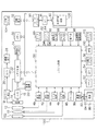
図1は、本発明を適用した実施形態に係るデジタルカメラ100の構成を示す図である。10は撮影レンズである。12は絞り機能を備えるシャッターである。14は光学像を電気信号に変換する撮像素子であり、本発明でいう撮像手段がこれに相当する。16は撮像素子14のアナログ信号出力をデジタル信号に変換するA/D変換器である。18は撮像素子14、A/D変換器16、D/A変換器26にクロック信号や制御信号を供給するタイミング発生回路であり、メモリ制御回路22及びシステム制御回路50により制御される。
Preferred embodiments of the present invention will be described below with reference to the accompanying drawings.
FIG. 1 is a diagram showing a configuration of a
20は画像処理回路であり、A/D変換器16からのデータ或いはメモリ制御回路22からのデータに対して所定の画素補間処理や色変換処理を行う。また、画像処理回路20は、撮像した画像データを用いて所定の演算処理を行い、得られた演算結果に基づいてシステム制御回路50が露光制御部40、測距制御部42に対して制御を行う。これにより、TTL(スルー・ザ・レンズ)方式のAF(オートフォーカス)処理、AE(自動露出)処理、EF(フラッシュプリ発光)処理を行う。さらに、画像処理回路20は、撮像した画像データを用いて所定の演算処理を行い、得られた演算結果に基づいてTTL方式のAWB(オートホワイトバランス)処理も行う。
An
22はメモリ制御回路であり、A/D変換器16、タイミング発生回路18、画像処理回路20、画像表示メモリ24、D/A変換器26、メモリ30、圧縮・伸長回路32を制御する。A/D変換器16のデータが画像処理回路20、メモリ制御回路22を介して、或いはA/D変換器16のデータが直接メモリ制御回路22を介して、画像表示メモリ24或いはメモリ30に書き込まれる。
A
24は画像表示メモリである。26はD/A変換器である。28はTFT LCD等からなる画像表示部であり、画像表示メモリ24に書き込まれた表示用の画像データはD/A変換器26を介して画像表示部28により表示される。画像表示部28を用いて撮像した画像データを逐次表示すれば、電子ファインダ機能を実現することが可能である。また、画像表示部28は、システム制御回路50の指示により任意に表示をON/OFFすることが可能であり、表示をOFFにした場合にはデジタルカメラ100の電力消費を大幅に低減することができる。
30は撮影した静止画像や動画像を格納するためのメモリであり、所定枚数の静止画像や所定時間の動画像を格納するのに十分な記憶量を備えている。これにより、複数枚の静止画像を連続して撮影する連射撮影やパノラマ撮影の場合にも、高速かつ大量の画像書き込みをメモリ30に対して行うことが可能となる。また、メモリ30はシステム制御回路50の作業領域としても使用することが可能である。
32は適応離散コサイン変換(ADCT)等により画像データを圧縮伸長する圧縮・伸長回路であり、メモリ30に格納された画像を読み込んで圧縮処理或いは伸長処理を行い、処理を終えたデータをメモリ30に書き込む。
40は絞り機能を備えるシャッター12を制御する露光制御部であり、フラッシュ48と連携することによりフラッシュ調光機能も有する。42は撮影レンズ10のフォーカシングを制御する測距制御部である。露光制御部40、測距制御部42はTTL方式を用いて制御され、撮像した画像データを画像処理回路20によって演算した演算結果に基づき、システム制御回路50が露光制御部40、測距制御部42に対して制御を行う。
44は撮影レンズ10のズーミングを制御するズーム制御部である。46はバリア102の動作を制御するバリア制御部である。48はAF補助光の投光機能、フラッシュ調光機能も有するフラッシュである。
A
50はデジタルカメラ100全体を制御するシステム制御回路であり、本発明でいう制御手段がこれに相当する。52はシステム制御回路50の動作用の定数、変数、プログラム等を記憶するメモリである。
54はシステム制御回路50でのプログラムの実行に応じて、文字、画像、音声等を用いて動作状態やメッセージ等を表示する液晶表示装置、スピーカー等の表示部である。表示部54は、デジタルカメラ100の操作部近辺の視認し易い位置に単数或いは複数個所設置され、例えばLCDやLED、発音素子等の組み合わせにより構成される。また、表示部54は、その一部の機能が光学ファインダ104内に設置されている。表示部54の表示内容のうち、LCD等に表示するものとしては、シングルショット/連写撮影表示、セルフタイマー表示、圧縮率表示、記録画素数表示、記録枚数表示、残撮影可能枚数表示、シャッタースピード表示、絞り値表示、露出補正表示、フラッシュ表示、赤目緩和表示、マクロ撮影表示、ブザー設定表示、時計用電池残量表示、電池残量表示、エラー表示、複数桁の数字による情報表示、外部記録媒体120の着脱状態表示、通信I/F動作表示、日付け・時刻表示等がある。また、表示部54の表示内容のうち、光学ファインダ104内に表示するものとしては、合焦表示、手振れ警告表示、フラッシュ充電表示、シャッタースピード表示、絞り値表示、露出補正表示等がある。
56は電気的に消去・記録可能な不揮発性メモリであり、例えばEEPROM等が用いられる。
60、62、64、66、68、及び70は、システム制御回路50の各種の動作指示を入力するための操作手段であり、スイッチやダイアル、タッチパネル、視線検知によるポインティング、音声認識装置等の単数或いは複数の組み合わせで構成される。
ここで、これらの操作手段の具体的な説明を行う。60はモードダイアルスイッチであり、電源オフ、自動撮影モード、撮影モード、パノラマ撮影モード、再生モード、マルチ画面再生・消去モード、PC接続モード等の各機能モードを切り替え設定することができる。
Here, a specific description of these operating means will be given.
62はシャッタースイッチSW1であり、不図示のシャッターボタンの操作途中でONとなり、AF処理、AE処理、AWB処理、EF処理等の動作開始を指示する。64はシャッタースイッチSW2であり、不図示のシャッターボタンの操作完了でONとなり、撮像素子14から読み出した信号をA/D変換器16、メモリ制御回路22を介してメモリ30に画像データを書き込む露光処理、画像処理回路20やメモリ制御回路22での演算を用いた現像処理、メモリ30から画像データを読み出し、圧縮・伸長回路32で圧縮を行い、記録媒体120に画像データを書き込む記録処理という一連の処理の動作開始を指示する。
66は画像表示ON/OFFスイッチであり、画像表示部28のON/OFFを設定することができる。この機能により、光学ファインダ104を用いて撮影を行う際に、画像表示部28への電流供給を遮断することにより、省電力を図ることが可能となる。
68はクイックレビューON/OFFスイッチであり、撮影直後に撮影した画像データを自動再生するクイックレビュー機能を設定する。なお、本実施形態では、特に画像表示部28をOFFとした場合におけるクイックレビュー機能を設定する機能を備えるものとする。
70は各種ボタンやタッチパネル等からなる操作部であり、メニューボタン、セットボタン、マクロボタン、マルチ画面再生改ページボタン、フラッシュ設定ボタン、単写/連写/セルフタイマー切り替えボタン、メニュー移動+(プラス)ボタン、メニュー移動−(マイナス)ボタン、再生画像移動+(プラス)ボタン、再生画像−(マイナス)ボタン、撮影画質選択ボタン、露出補正ボタン、日付/時間設定ボタン等がある。
80は電源制御部であり、電池検出回路、DC-DCコンバータ、通電するブロックを切り替えるスイッチ回路等により構成される。電源制御部80は、電池の装着の有無、電池の種類、電池残量の検出を行い、検出結果及びシステム制御回路50の指示に基づいてDC-DCコンバータを制御し、必要な電圧を必要な期間、記録媒体を含む各部へ供給する。
A
82、84はコネクタである。86は電源であり、アルカリ電池やリチウム電池等の一次電池やNiCd電池やNiMH電池、Li電池等の二次電池、ACアダプタ等からなる。
82 and 84 are connectors. A
90はメモリカード等の外部記録媒体とデータの送受信を行うカードコントローラである。91はメモリカード等の外部記録媒体とのインタフェースである。92はメモリカード等の外部記録媒体120と接続を行うコネクタである。98はコネクタ92に外部記録媒体120が装着されているか否かを検知する記録媒体着脱検知部である。
A
なお、本実施形態では、記録媒体を取り付けるインタフェースやコネクタは、単数或いは複数、いずれの系統数を備える構成としても構わない。また、異なる規格のインタフェース及びコネクタを組み合わせて備える構成としても構わない。インタフェース及びコネクタとしては、PCMCIAカードやCF(コンパクトフラッシュ(登録商標))カード等の規格に準拠したものを用いて構成して構わない。 In the present embodiment, the interface or connector to which the recording medium is attached may have a single or a plurality of systems, any number of systems. Moreover, it is good also as a structure provided with combining the interface and connector of a different standard. The interface and the connector may be configured using a PCMCIA card, a CF (Compact Flash (registered trademark)) card, or the like based on a standard.
さらに、インタフェース91、そしてコネクタ92をPCMCIAカードやCF(コンパクトフラッシュ(登録商標))カード等の規格に準拠したものを用いて構成した場合、各種通信カードを接続することができる。通信カードは、LANカードやモデムカード、USBカード、IEEE1394カード、P1284カード、SCSIカード、PHS等の通信カード等である。そして、各種通信カードを接続することにより、他のコンピュータやプリンタ等の周辺機器との間で画像データや画像データに付属した管理情報を転送し合うことができる。
Furthermore, when the
102は保護手段としてのバリアであり、デジタルカメラ100のレンズ10を含む撮像部を覆うことにより、撮像部の汚れや破損を防止する。
104は光学ファインダであり、画像表示部28による電子ファインダ機能を使用すること無しに、光学ファインダのみを用いて撮影を行うことが可能である。また、光学ファインダ104内には、表示部54の一部の機能、例えば、合焦表示、手振れ警告表示、フラッシュ充電表示、シャッタースピード表示、絞り値表示、露出補正表示等が設置されている。
Reference numeral 104 denotes an optical viewfinder, which can take an image using only the optical viewfinder without using the electronic viewfinder function of the
120はメモリカード等の外部記録媒体であり、デジタルカメラ100に着脱可能に装着される。本実施形態に係るデジタルカメラ100では、同一のアドレスに対してデータの再書き込みが可能な記録媒体、及び、同一のアドレスに対してデータの再書き込みが不可能な記録媒体のいずれも装着可能となっている。前者の記録媒体が本発明でいう第1の記録媒体に相当し、後者の記録媒体が本発明でいう第2の記録媒体に相当するものである。
An
次に、図2、図3、図4を参照して、本実施形態に係るデジタルカメラ100の処理動作を説明する。
Next, processing operations of the
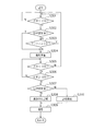
図2は、本実施形態に係るデジタルカメラ100の起動時の処理動作を示すフローチャートである。電源投入後、ステップS201で、システム制御回路50は、日時設定済みか否かを判定する。上記ステップS201において日時設定済みでない場合、ステップS202に進み、日時設定画面を表示する。なお、上記ステップS201において日時設定済みである場合は、そのまま撮影待機状態になる。
FIG. 2 is a flowchart showing a processing operation at the time of starting the
次に、ステップS203で、システム制御回路50は、カードコントローラ90を介して、コネクタ92に装着されている記録媒体が、同一のアドレスに対してデータの再書き込みが不可能な記録媒体(ワンタイムSD)であるか否かを判定する。これが本発明でいう判定手段による処理例である。
Next, in step S203, the
上記ステップS203においてワンタイムSDでない場合、ステップS204に進み、操作部70にあるキャンセルボタンが押されたか否かを判定する。
If it is not the one-time SD in step S203, the process proceeds to step S204, and it is determined whether or not the cancel button on the
上記ステップS204においてキャンセルボタンが押されていない場合、ステップS205に進み、日時設定が完了したか否かを判定する。なお、上記ステップS203においてワンタイムSDである場合は、ステップS205に進み、日時設定が完了したか否かを判定する。 If the cancel button has not been pressed in step S204, the process proceeds to step S205, and it is determined whether date and time setting has been completed. If it is the one-time SD in step S203, the process proceeds to step S205 to determine whether the date / time setting is completed.
上記ステップS205において日時設定が完了していない場合、ステップS206に進み、システム制御回路50は、シャッタースイッチSW1が押されたか否かを判定する。上記ステップS206においてシャッタースイッチSW1が押された場合、ステップS207に進み、日時設定画面を消去し、ステップS208に進み、AF処理、AE処理、AWB処理等の撮影準備動作をする。なお、上記ステップS206においてシャッタースイッチSW1が押されていない場合は、ステップS203に戻る。
If the date and time setting is not completed in step S205, the process proceeds to step S206, and the
上記ステップS204においてキャンセルボタンが押された場合や、上記ステップS205において日時設定が完了した場合、システム制御回路50は、ステップS209に進み、日時設定画面を消去し、撮影待機状態になる。
When the cancel button is pressed in step S204 or when the date and time setting is completed in step S205, the
図3は、本実施形態に係るデジタルカメラ100の撮影待機状態から撮影までの処理動作を示すフローチャートである。撮影待機状態において、ステップS301で、システム制御回路50は、シャッタースイッチSW1が押されたか否かを判定する。上記ステップS301においてシャッタースイッチSW1が押された場合、ステップS302に進み、日時設定がされているか否かを判定する。なお、上記ステップS301においてシャッタースイッチSW1が押されていない場合は、シャッタースイッチSW1が押されるまで待機する。
FIG. 3 is a flowchart showing processing operations from the shooting standby state to shooting of the
上記ステップS302において日時設定がされていなかった場合、ステップS303に進み、システム制御回路50は、カードコントローラ90を介して、コネクタ92に装着されている記録媒体がワンタイムSDであるか否かを判定する。これが本発明でいう判定手段による処理例である。
If the date and time have not been set in step S302, the process proceeds to step S303, and the
上記ステップS303においてワンタイムSDでない場合、また、上記ステップS302において日時設定がされている場合、ステップS304に進み、AF処理、AE処理、AWB処理等の撮影準備動作をする。なお、上記ステップS303においてワンタイムSDである場合は、ステップS301に戻り、撮影待機状態のままとなる。すなわち、ワンタイムSDが装着されており、日時設定がなされていないときは、撮影を禁止する。 If it is not the one-time SD in step S303, or if the date and time is set in step S302, the process proceeds to step S304, and shooting preparation operations such as AF processing, AE processing, and AWB processing are performed. If it is the one-time SD in step S303, the process returns to step S301 and remains in the shooting standby state. That is, shooting is prohibited when the one-time SD is attached and the date and time are not set.
ステップS304の撮影準備動作が完了すると、ステップS305で、システム制御回路50は、シャッタースイッチSW1が押されているか否かを判定する。上記ステップS305においてシャッタースイッチSW1が押されている場合、ステップS306に進み、シャッタースイッチSW2が押されたか否かを判定する。なお、上記ステップS305においてシャッタースイッチSW1が押されていない場合は、ステップS301に戻り、撮影待機状態となる。
When the shooting preparation operation in step S304 is completed, in step S305, the
上記ステップS306においてシャッタースイッチSW2が押された場合、ステップS307に進み、日時設定がされているか否かを判定する。なお、上記ステップS306において、シャッタースイッチSW2が押されていない場合は、ステップS305に戻り、シャッタースイッチSW1が押されているか否かを判定する。 If the shutter switch SW2 is pressed in step S306, the process proceeds to step S307, where it is determined whether date and time have been set. If it is determined in step S306 that the shutter switch SW2 has not been pressed, the process returns to step S305 to determine whether the shutter switch SW1 has been pressed.
上記ステップS307において日時設定がされている場合、ステップS308に進み、現在の時刻を撮影時刻としてメモリ52に記憶する。ステップS308の撮影時刻の記憶が完了すると、ステップS309に進み、露光処理、現像処理、圧縮処理という一連の撮影処理を行う。また、上記ステップS307において日時設定がされていない場合は、ステップS310に進み、システム制御回路50にあるタイマーを動作させ、計時を開始し、ステップS309に進み、一連の撮影処理を行う。
If the date and time is set in step S307, the process proceeds to step S308, and the current time is stored in the
図4は、本実施形態に係るデジタルカメラ100の撮影から記録までの処理動作を示すフローチャートである。一連の撮影処理が完了すると、ステップS401で、システム制御回路50は、日時設定がされているか否かを判定する。上記ステップS401において日時設定がされている場合、ステップS402に進み、システム制御回路50は、カードコントローラ90を介して、コネクタ92に装着されている記録媒体がワンタイムSDであるか否かを判定する。これが本発明でいう判定手段による処理例である。なお、上記ステップS401において日時設定済みである場合は、ステップS408に進む。
FIG. 4 is a flowchart showing processing operations from photographing to recording of the
上記ステップS402においてワンタイムSDである場合、ステップS403に進み、日時設定画面を表示した後、ステップS404に進み、日時設定が完了したか否かを判定し、完了するまで待機する。すなわち、ワンタイムSDが装着されており、日時設定がなされていないときは、記録前に日時設定させる。 If it is the one-time SD in step S402, the process proceeds to step S403, and the date / time setting screen is displayed. Then, the process proceeds to step S404, where it is determined whether the date / time setting is completed, and waits until completion. That is, when the one-time SD is attached and the date / time is not set, the date / time is set before recording.
上記ステップS404において日時設定が完了した場合、ステップS405に進み、ステップS310で開始した計時を終了し、設定された日時から計時された時間を減算することにより撮影時刻を算出する。次に、ステップS406に進み、撮影時刻としてメモリ52に記憶する。次に、ステップS407に進み、日時設定画面を消去する。その後、ステップS408に進み、ステップS309で撮影処理された画像データとメモリ52に記憶されている撮影時刻を1つのファイルとしてコネクタ92に装着されている記録媒体に記録する。これが本発明でいうデータ記録手段による処理例である。
When the date and time setting is completed in step S404, the process proceeds to step S405, where the time measurement started in step S310 is terminated, and the shooting time is calculated by subtracting the time measured from the set date and time. Next, the process proceeds to step S406 and is stored in the
上記ステップS402においてワンタイムSDでない場合は、ステップS408に進み、撮影時刻が記憶されていないため、撮影時刻が不定のまま記録媒体に記録する。また、上記ステップS401において日時設定済みである場合は、ステップS309で撮影処理された画像データとメモリ52に記憶されている撮影時刻を1つのファイルとしてコネクタ92に装着されている記録媒体に記録する。
If the one-time SD is not determined in step S402, the process proceeds to step S408, and the shooting time is not stored. If the date and time has been set in step S401, the image data captured in step S309 and the shooting time stored in the
本実施形態では、ワンタイムSD使用時の所定の動作変更の対象となる付加情報の設定を、日時情報の設定として説明した。ただし、それ以外にも、撮影者情報(オーナーネーム)、撮影した画像のカテゴリを識別するためのタグ情報、撮影時のカメラの回転方向を示す回転情報、撮影した位置に関するGPS情報等のファイル情報として必要な付加情報に関する設定にも適用しうる。 In the present embodiment, the setting of the additional information that is the target of the predetermined operation change when using the one-time SD has been described as the setting of the date / time information. However, in addition to this, file information such as photographer information (owner name), tag information for identifying the category of the photographed image, rotation information indicating the rotation direction of the camera at the time of photographing, GPS information regarding the photographing position, etc. It can also be applied to settings related to additional information required.
また、ワンタイムSD使用時の所定の動作変更の対象となる付加情報の設定を、メニュー等でユーザが選択できるようにしても良い。 Further, the user may be able to select a setting of additional information that is a target of a predetermined operation change when using the one-time SD by using a menu or the like.
以上説明したように、ワンタイムSDを使用する際に、ファイル情報として必要な付加情報に関する設定がされていない場合に、記録媒体に記録する前にその設定をさせることにより、不要なファイル作成による記録容量の消費を防ぎ、該記録媒体を有効に使用することができる。 As described above, when one-time SD is used, if additional information necessary as file information is not set, the setting is made before recording on the recording medium, thereby creating an unnecessary file. Consumption of the recording capacity can be prevented and the recording medium can be used effectively.
なお、本発明の目的は、上述した実施形態の機能を実現するソフトウェアのプログラムコードを記録した記憶媒体を、システム或いは装置に供給することによっても達成される。この場合、そのシステム或いは装置のコンピュータ(又はCPUやMPU)が記憶媒体に格納されたプログラムコードを読み出し実行する。 The object of the present invention can also be achieved by supplying a storage medium storing software program codes for realizing the functions of the above-described embodiments to a system or apparatus. In this case, the computer (or CPU or MPU) of the system or apparatus reads and executes the program code stored in the storage medium.
この場合、記憶媒体から読み出されたプログラムコード自体が上述した実施形態の機能を実現することになり、プログラムコード自体及びそのプログラムコードを記憶した記憶媒体は本発明を構成することになる。 In this case, the program code itself read from the storage medium realizes the functions of the above-described embodiments, and the program code itself and the storage medium storing the program code constitute the present invention.
プログラムコードを供給するための記憶媒体としては、例えば、フレキシブルディスク、ハードディスク、光ディスク、光磁気ディスク、CD−ROM、CD−R、磁気テープ、不揮発性のメモリカード、ROM等を用いることができる。 As a storage medium for supplying the program code, for example, a flexible disk, a hard disk, an optical disk, a magneto-optical disk, a CD-ROM, a CD-R, a magnetic tape, a nonvolatile memory card, a ROM, or the like can be used.
また、コンピュータが読み出したプログラムコードを実行することにより、上述した実施形態の機能が実現されるだけに限らない。例えば、そのプログラムコードの指示に基づき、コンピュータ上で稼動しているOS(基本システム或いはオペレーティングシステム)等が実際の処理の一部又は全部を行い、その処理によって上述した実施形態の機能が実現されてもよい。 Further, the functions of the above-described embodiments are not limited to being realized by executing the program code read by the computer. For example, an OS (basic system or operating system) running on the computer performs part or all of the actual processing based on an instruction of the program code, and the functions of the above-described embodiments are realized by the processing. May be.
さらに、記憶媒体から読み出されたプログラムコードが、コンピュータに挿入された機能拡張ボードやコンピュータに接続された機能拡張ユニットに備わるメモリに書き込まれる形態でもよい。この場合メモリに書き込まれた後、そのプログラムコードの指示に基づき、その機能拡張ボードや機能拡張ユニットに備わるCPU等が実際の処理の一部又は全部を行い、その処理によって上述した実施形態の機能が実現される。 Further, the program code read from the storage medium may be written in a memory provided in a function expansion board inserted into the computer or a function expansion unit connected to the computer. In this case, after being written in the memory, the CPU of the function expansion board or function expansion unit performs part or all of the actual processing based on the instruction of the program code, and the function of the above-described embodiment is performed by the processing. Is realized.
10:撮影レンズ
12:シャッター
14:撮像素子
16:A/D変換器
18:タイミング発生回路
20:画像処理回路
22:メモリ制御回路
24:画像表示メモリ
26:D/A変換器
28:画像表示部
30:メモリ
32:圧縮・伸長回路
40:露光制御部
42:測距制御部
44:ズーム制御部
46:バリア制御部
48:フラッシュ
50:システム制御回路
52:メモリ
54:表示部
56:不揮発性メモリ
90:カードコントローラ
91:インタフェース
92:コネクタ
98:記録媒体着脱検知部
100:デジタルカメラ
120:外部記録媒体
DESCRIPTION OF SYMBOLS 10: Shooting lens 12: Shutter 14: Image pick-up element 16: A / D converter 18: Timing generation circuit 20: Image processing circuit 22: Memory control circuit 24: Image display memory 26: D / A converter 28: Image display part 30: Memory 32: Compression / decompression circuit 40: Exposure control unit 42: Distance measurement control unit 44: Zoom control unit 46: Barrier control unit 48: Flash 50: System control circuit 52: Memory 54: Display unit 56: Non-volatile memory 90: Card controller 91: Interface 92: Connector 98: Recording medium attachment / detachment detection unit 100: Digital camera 120: External recording medium
Claims (5)
撮像手段と、
前記撮像手段により得られた画像データ及び前記画像データに関する付加情報を前記記録媒体に記録するデータ記録手段と、
前記記録媒体として、同一のアドレスに対してデータの再書き込みが可能な第1の記録媒体、及び、同一のアドレスに対してデータの再書き込みが不可能な第2の記録媒体のいずれが装着されているかを判定する判定手段と、
前記判定手段による判別結果により前記第1の記録媒体が装着されていると判定された場合と、前記第2の記録媒体が装着されていると判定された場合とで、前記付加情報の設定がなされていない状態での前記撮像手段又は前記データ記録手段に関する動作を異ならしめる制御手段とを備えたことを特徴とする撮像装置。 An imaging device on which a recording medium is detachably mounted,
Imaging means;
Data recording means for recording image data obtained by the imaging means and additional information related to the image data on the recording medium;
As the recording medium, the first recording medium capable of rewriting data for the same address, and any are mounted in the second recording medium that can not be re-writing of data to the same address Determining means for determining whether or not
The setting of the additional information is performed when it is determined that the first recording medium is mounted according to a determination result by the determination unit, and when it is determined that the second recording medium is mounted. imaging apparatus characterized by comprising a control means made different operations relating to the image pickup means or said data recording means in a state that is not made.
前記着脱可能に装着される記録媒体として、同一のアドレスに対してデータの再書き込みが可能な第1の記録媒体、及び、同一のアドレスに対してデータの再書き込みが不可能な第2の記録媒体のいずれが装着されているかを判定するステップと、
前記判定による判別結果により前記第1の記録媒体が装着されていると判定された場合と、前記第2の記録媒体が装着されていると判定された場合とで、前記付加情報の設定がなされていない状態での前記撮像手段又は前記データ記録手段に関する動作を異ならしめるステップを有することを特徴とする撮像装置の制御方法。 An imaging unit, the additional information relating to the image data and the image data obtained by the imaging unit, a control method of an imaging device and a data recording means for recording on a recording medium which is detachably mounted,
As the detachably mounted recording medium, a first recording medium that can rewrite data to the same address, and a second recording that cannot rewrite data to the same address Determining which of the media is loaded;
The additional information is set when it is determined that the first recording medium is mounted according to the determination result of the determination, and when it is determined that the second recording medium is mounted. A control method for an image pickup apparatus, comprising the step of differentiating operations relating to the image pickup means or the data recording means in a state where the image pickup means is not in operation.
前記着脱可能に装着される記録媒体として、同一のアドレスに対してデータの再書き込みが可能な第1の記録媒体、及び、同一のアドレスに対してデータの再書き込みが不可能な第2の記録媒体のいずれが装着されているかを判定する処理と、
前記判定による判別結果により前記第1の記録媒体が装着されていると判定された場合と、前記第2の記録媒体が装着されていると判定された場合とで、前記付加情報の設定がなされていない状態での前記撮像手段又は前記データ記録手段に関する動作を異ならしめる処理をコンピュータに実行させるためのプログラム。 An imaging unit, the additional information relating to the image data and the image data obtained by the imaging means, a program for controlling an image pickup apparatus and a data recording means for recording on a recording medium which is detachably mounted And
As the detachably mounted recording medium, a first recording medium that can rewrite data to the same address, and a second recording that cannot rewrite data to the same address A process of determining which medium is loaded;
The additional information is set when it is determined that the first recording medium is mounted according to the determination result of the determination, and when it is determined that the second recording medium is mounted. A program for causing a computer to execute a process for making the operation relating to the imaging unit or the data recording unit different in a state where the computer is not in operation.
Priority Applications (1)
| Application Number | Priority Date | Filing Date | Title |
|---|---|---|---|
| JP2007076766A JP4785778B2 (en) | 2007-03-23 | 2007-03-23 | Imaging device, control method thereof, and program |
Applications Claiming Priority (1)
| Application Number | Priority Date | Filing Date | Title |
|---|---|---|---|
| JP2007076766A JP4785778B2 (en) | 2007-03-23 | 2007-03-23 | Imaging device, control method thereof, and program |
Publications (3)
| Publication Number | Publication Date |
|---|---|
| JP2008236639A JP2008236639A (en) | 2008-10-02 |
| JP2008236639A5 JP2008236639A5 (en) | 2010-04-30 |
| JP4785778B2 true JP4785778B2 (en) | 2011-10-05 |
Family
ID=39908829
Family Applications (1)
| Application Number | Title | Priority Date | Filing Date |
|---|---|---|---|
| JP2007076766A Expired - Fee Related JP4785778B2 (en) | 2007-03-23 | 2007-03-23 | Imaging device, control method thereof, and program |
Country Status (1)
| Country | Link |
|---|---|
| JP (1) | JP4785778B2 (en) |
Families Citing this family (1)
| Publication number | Priority date | Publication date | Assignee | Title |
|---|---|---|---|---|
| JP5968086B2 (en) * | 2012-05-31 | 2016-08-10 | キヤノン株式会社 | Imaging apparatus and control method thereof |
Family Cites Families (4)
| Publication number | Priority date | Publication date | Assignee | Title |
|---|---|---|---|---|
| JP2003009067A (en) * | 2001-06-21 | 2003-01-10 | Nti:Kk | Digital camera provided with photographing record input function |
| JP2003209774A (en) * | 2002-01-11 | 2003-07-25 | Nikon Gijutsu Kobo:Kk | Digital camera and storage medium |
| JP2004064677A (en) * | 2002-07-31 | 2004-02-26 | Victor Co Of Japan Ltd | Digital camera |
| JP2004242260A (en) * | 2003-02-10 | 2004-08-26 | Canon Inc | Image pickup device |
-
2007
- 2007-03-23 JP JP2007076766A patent/JP4785778B2/en not_active Expired - Fee Related
Also Published As
| Publication number | Publication date |
|---|---|
| JP2008236639A (en) | 2008-10-02 |
Similar Documents
| Publication | Publication Date | Title |
|---|---|---|
| US7084921B1 (en) | Image processing apparatus with another display unit its control method, and recording medium | |
| JP2005176136A (en) | Image processor, image reproducing method, program and recording medium | |
| JP4387559B2 (en) | Imaging device | |
| JP2006119996A (en) | Battery-driven device and its nonvolatile memory updating method | |
| JP4498169B2 (en) | Image processing apparatus and control method thereof | |
| JP4646725B2 (en) | IMAGING DEVICE AND IMAGING DEVICE CONTROL METHOD | |
| JP4681937B2 (en) | Imaging apparatus and imaging method | |
| JP4700796B2 (en) | Imaging apparatus, control method therefor, and storage medium | |
| JP2006203689A (en) | Imaging apparatus and control method thereof, program, and storage medium | |
| JP4261815B2 (en) | Imaging device | |
| JP4785778B2 (en) | Imaging device, control method thereof, and program | |
| JP4981478B2 (en) | Imaging device | |
| JP2008072516A (en) | Image processing apparatus and image processing method | |
| JP2005221771A (en) | Imaging device and function display method | |
| JP2007158604A (en) | Imaging apparatus and its control method | |
| JP2002077715A (en) | Image processor and image processing method and computer readable storage medium | |
| JP4574426B2 (en) | Data processing apparatus and data processing method | |
| JP4878456B2 (en) | Recording medium and imaging apparatus | |
| JP4836233B2 (en) | Image processing apparatus, control method therefor, computer program, and storage medium | |
| JP4298534B2 (en) | Image display apparatus and method | |
| JP4701297B2 (en) | Image processing apparatus, method, and recording medium | |
| JP2006202051A (en) | Data processor and data processing method | |
| JP3697215B2 (en) | Imaging device | |
| JP4217411B2 (en) | Image processing apparatus, image processing method, recording medium, and program | |
| JP4971640B2 (en) | Imaging device |
Legal Events
| Date | Code | Title | Description |
|---|---|---|---|
| A521 | Request for written amendment filed |
Free format text: JAPANESE INTERMEDIATE CODE: A523 Effective date: 20100312 |
|
| A621 | Written request for application examination |
Free format text: JAPANESE INTERMEDIATE CODE: A621 Effective date: 20100312 |
|
| A977 | Report on retrieval |
Free format text: JAPANESE INTERMEDIATE CODE: A971007 Effective date: 20110630 |
|
| TRDD | Decision of grant or rejection written | ||
| A01 | Written decision to grant a patent or to grant a registration (utility model) |
Free format text: JAPANESE INTERMEDIATE CODE: A01 Effective date: 20110705 |
|
| A01 | Written decision to grant a patent or to grant a registration (utility model) |
Free format text: JAPANESE INTERMEDIATE CODE: A01 |
|
| A61 | First payment of annual fees (during grant procedure) |
Free format text: JAPANESE INTERMEDIATE CODE: A61 Effective date: 20110712 |
|
| FPAY | Renewal fee payment (event date is renewal date of database) |
Free format text: PAYMENT UNTIL: 20140722 Year of fee payment: 3 |
|
| LAPS | Cancellation because of no payment of annual fees |