JP4681937B2 - Imaging apparatus and imaging method - Google Patents
Imaging apparatus and imaging method Download PDFInfo
- Publication number
- JP4681937B2 JP4681937B2 JP2005148557A JP2005148557A JP4681937B2 JP 4681937 B2 JP4681937 B2 JP 4681937B2 JP 2005148557 A JP2005148557 A JP 2005148557A JP 2005148557 A JP2005148557 A JP 2005148557A JP 4681937 B2 JP4681937 B2 JP 4681937B2
- Authority
- JP
- Japan
- Prior art keywords
- image data
- recording
- moving image
- recording area
- recorded
- Prior art date
- Legal status (The legal status is an assumption and is not a legal conclusion. Google has not performed a legal analysis and makes no representation as to the accuracy of the status listed.)
- Expired - Fee Related
Links
Images


Description
本発明は、動画像撮影中に静止画像を記録可能な撮像技術に関するものである。 The present invention relates to an imaging technique capable of recording a still image during moving image shooting.
一般的に、CCD等の撮像素子によりデジタル画像を記録するデジタルカメラには、静止画像を記録するだけではなく、動画像を記録する機能が搭載されている。 In general, a digital camera that records a digital image using an image pickup device such as a CCD is equipped with a function of recording not only a still image but also a moving image.
このようなデジタルカメラに対しては、動画像を撮影中に任意のタイミングで静止画像を記録する機能が求められており、動画像の撮影中に動画像の1フレーム分に相当する静止画像をスナップショットとして記録することが可能なデジタルカメラが提供されている。 Such a digital camera is required to have a function of recording a still image at an arbitrary timing during shooting of a moving image, and a still image corresponding to one frame of the moving image during shooting of the moving image is required. A digital camera capable of recording as a snapshot is provided.
上記のようなデジタルカメラにおいては、静止画像データをスナップショットとして退避・保存するための専用の記憶領域が設けられているが、この専用の記憶領域はスナップショットの記録指示がなされるまでは使用されず、その分動画像記録のための記憶領域が減らされていることから、円滑な動画像記録の妨げとなっている。 The digital camera as described above has a dedicated storage area for saving and saving still image data as a snapshot. This dedicated storage area is used until a snapshot recording instruction is issued. However, since the storage area for moving image recording is reduced by that amount, smooth moving image recording is hindered.
これに対して、特許文献1に記載のように、スナップショットのための記憶領域と動画像記録のための記憶領域とを共用とすることで、メモリを効率的に使用しながら動画像の記録を円滑に行うことが可能なデジタルカメラが提案されている。
前述したスナップショットのための記憶領域と動画像記録のための記憶領域とを共用するデジタルカメラにおいては、動画像撮影中にスナップショットの記録を指示すると、前述の共用記憶領域が消費されて動画像撮影のための記憶領域が不足し、動画像の撮影に支障を来たすことがあり、それは記録媒体への書き込み速度が低い場合ほど顕著である。 In a digital camera that shares the storage area for snapshots and the storage area for moving image recording, if the recording of the snapshot is instructed during moving image shooting, the shared storage area is consumed and the moving image is recorded. There is a shortage of storage area for image shooting, which may hinder the shooting of moving images, which is more remarkable when the writing speed to the recording medium is lower.
このような弊害を避けるために、前述の共用記憶領域の使用状況をLCDパネル等の画像表示部に表示することで、動画像撮影中にスナップショットの記録指示を行っても差し支えないかどうかをユーザが判断できるようにすることが考えられるが、前述の共用記憶領域の使用状況を動画像記録中に常に表示することは、画像表示部が見づらくなってしまうので好ましくない。 In order to avoid such an adverse effect, whether or not there is no problem in issuing a snapshot recording instruction during moving image shooting by displaying the use status of the above-mentioned shared storage area on an image display unit such as an LCD panel. Although it is conceivable for the user to be able to make a decision, it is not preferable to always display the use status of the above-mentioned shared storage area during moving image recording because the image display unit will be difficult to see.
また、常に前述の共用記憶領域の使用状況が表示されている場合、ユーザの注意がおろそかになる恐れもある。 In addition, when the use status of the above-mentioned shared storage area is always displayed, the user's attention may be neglected.
本発明は、上記課題を解決するためになされ、その目的は、ユーザに対して、動画像の記録と動画像撮影中の静止画像の記録のために共用される記憶領域の使用状況を分かりやすく通知することができる撮像技術を提供することにある。 The present invention has been made to solve the above-described problems, and its purpose is to make it easy for the user to understand the usage status of a storage area shared for recording moving images and recording still images during moving image shooting. An object of the present invention is to provide an imaging technique capable of notifying.
上記課題を解決し、目的を達成するために、本発明の撮像装置は、動画像撮影中に静止画像を記録する撮像装置であって、撮影された動画像データおよび動画像撮影中に撮影された静止画像データを一時的に記録する記録手段であって、前記動画像データを記録するための記録領域に、前記静止画像データを記録する記録手段と、前記記録領域に記録されている前記動画像データを記録媒体に書き込む際の動画像データの書き込み速度を検出する検出手段と、動画像撮影中に、前記検出手段によって前記動画像データの書き込み速度が所定値より低いことを検出した場合、前記記録領域の使用状況を表示する表示手段とを具備する。
また、本発明の撮像装置は、動画像撮影中に静止画像を記録する撮像装置であって、撮影された動画像データおよび動画像撮影中に撮影された静止画像データを一時的に記録する記録手段であって、前記動画像データを記録するための記録領域に、前記静止画像データを記録する記録手段と、前記記録領域に記録されている前記動画像データを記録媒体に書き込む際の動画像データの書き込み速度を検出する検出手段と、動画像撮影中に、前記検出手段によって前記動画像データの書き込み速度が所定値より低いことを検出した場合、前記記録領域の使用状況を表示する表示手段とを具備し、前記表示手段は、動画像撮影中に、前記動画像データの書き込み速度が前記所定値以上である場合、又は前記動画像データの書き込み速度が前記所定値より低い場合であっても前記記録領域の空き容量が所定容量より大きいならば、前記記録領域の使用状況の表示を行わない。
In order to solve the above-described problems and achieve the object, an imaging apparatus according to the present invention is an imaging apparatus that records a still image during moving image shooting, and is shot during moving image shooting and moving image shooting still image data a recording unit for temporarily recording, the recording area for recording the moving image data, and recording means for recording the still image data, the moving image recorded in the recording area Detecting means for detecting the writing speed of moving image data when writing image data to a recording medium; and when detecting that the writing speed of the moving image data is lower than a predetermined value by the detecting means during moving image shooting, Display means for displaying the usage status of the recording area .
The imaging device of the present invention is an imaging device that records a still image during moving image shooting, and is a recording that temporarily records the captured moving image data and still image data shot during the moving image shooting. A recording means for recording the still image data in a recording area for recording the moving image data, and a moving image when the moving image data recorded in the recording area is written to a recording medium A detecting means for detecting a data writing speed; and a display means for displaying a usage status of the recording area when the detecting means detects that the writing speed of the moving image data is lower than a predetermined value during moving image shooting. And when the moving image data writing speed is equal to or higher than the predetermined value during moving image shooting, or the moving image data writing speed is the predetermined value. If the free space of the recording area even when lower is larger than the predetermined capacity, not displayed usage of the recording area.
また、本発明の撮像方法は、動画像撮影中に静止画像を記録する撮像方法であって、撮影された動画像データおよび動画像撮影中に撮影された静止画像データを一時的に記録する記録手段における、前記動画像データを記録するための記録領域に、前記静止画像データを記録する記録工程と、前記記録領域に記録されている前記動画像データを記録媒体に書き込む際の動画像データの書き込み速度を検出する検出工程と、動画像撮影中に、前記検出工程によって前記動画像データの書き込み速度が所定値より低いことを検出した場合、前記記録領域の使用状況を表示する表示工程とを備える。
また、本発明の撮像方法は、動画像撮影中に静止画像を記録する撮像方法であって、撮影された動画像データおよび動画像撮影中に撮影された静止画像データを一時的に記録する記録手段における、前記動画像データを記録するための記録領域に、前記静止画像データを記録する記録工程と、前記記録領域に記録されている前記動画像データを記録媒体に書き込む際の動画像データの書き込み速度を検出する検出工程と、動画像撮影中に、前記検出工程によって前記動画像データの書き込み速度が所定値より低いことを検出した場合、前記記録領域の使用状況を表示する表示工程とを備え、前記表示工程では、動画像撮影中に、前記動画像データの書き込み速度が前記所定値以上である場合、又は前記動画像データの書き込み速度が前記所定値より低い場合であっても前記記録領域の空き容量が所定容量より大きいならば、前記記録領域の使用状況の表示を行わない。
The imaging method of the present invention is an imaging method for recording a still image during moving image shooting, recording for temporarily storing still image data captured in the captured moving image data and moving image shooting in unit, the recording area for recording the moving image data, the still and recording process of recording the image data, the moving image data when writing to the recording medium the moving image data recorded in the recording area A detection step of detecting a writing speed; and a display step of displaying a usage status of the recording area when the moving speed of the moving image data is detected to be lower than a predetermined value during the moving image shooting. Prepare.
The imaging method of the present invention is an imaging method for recording a still image during moving image shooting, recording for temporarily storing still image data captured in the captured moving image data and moving image shooting in unit, the recording area for recording the moving image data, the still and recording process of recording the image data, the moving image data when writing to the recording medium the moving image data recorded in the recording area A detection step of detecting a writing speed; and a display step of displaying a usage status of the recording area when the moving speed of the moving image data is detected to be lower than a predetermined value during the moving image shooting. And in the display step, when the moving image data writing speed is equal to or higher than the predetermined value during moving image shooting, or the moving image data writing speed is the predetermined value. If the free space of the recording area even when lower is larger than the predetermined capacity, not displayed usage of the recording area.
本発明によれば、記録媒体への書き込み速度が遅く、動画像の記録と動画像撮影中の静止画像の記録のために共用される記憶領域が消費されやすくなるような注意を喚起すべき状況でのみ、上記共用記憶領域の使用状況を表示するので、ユーザに対して共用記憶領域の使用状況を分かりやすく通知することができる。 According to the present invention, the writing speed to the recording medium is slow, and attention should be paid so that the storage area shared for recording moving images and recording still images during moving image shooting is likely to be consumed. Since the usage status of the shared storage area is displayed only in the above, the usage status of the shared storage area can be easily notified to the user.
以下に、添付図面を参照して本発明を実施するための最良の形態について詳細に説明する。 The best mode for carrying out the present invention will be described below in detail with reference to the accompanying drawings.
尚、以下に説明する実施の形態は、本発明の実現手段としての一例であり、本発明が適用される装置の構成や各種条件によって適宜修正又は変更されるべきものであり、本発明は以下の実施の形態に限定されるものではない。 The embodiment described below is an example as means for realizing the present invention, and should be appropriately modified or changed according to the configuration and various conditions of the apparatus to which the present invention is applied. It is not limited to the embodiment.
[装置の説明]
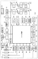
図1は、本発明に係る実施形態の撮像装置の構成を示すブロック図である。
[Description of device]
FIG. 1 is a block diagram illustrating a configuration of an imaging apparatus according to an embodiment of the present invention.
図1において、100は電子カメラ等に代表される撮像装置である。
In FIG. 1,
10は撮影レンズ、12は絞り機能を備えるシャッター、14は光学像を電気信号に変換する撮像素子、16は撮像素子14のアナログ信号出力をディジタル信号に変換するA/D変換部である。
18は撮像素子14、A/D変換部16、D/A変換部26にクロック信号や制御信号を供給するタイミング発生部であり、メモリ制御部22及びシステム制御部50により制御される。
A timing generator 18 supplies a clock signal and a control signal to the
20は画像処理部であり、A/D変換部16からのデータ或いはメモリ制御部22からのデータに対して所定の画素補間処理や色変換処理を行う。
An
また、画像処理部20においては、撮像した画像データを用いて所定の演算処理を行い、得られた演算結果に基づいてシステム制御部50が露光制御部40、測距制御部42に対して制御を行う、TTL(スルー・ザ・レンズ)方式のAF(オートフォーカス)処理、AE(自動露出)処理、EF(ストロボプリ発光)処理を行っている。
The
さらに、画像処理部20においては、撮像した画像データを用いて所定の演算処理を行い、得られた演算結果に基づいてTTL方式のAWB(オートホワイトバランス)処理も行っている。
Further, the
22はメモリ制御部であり、A/D変換部16、タイミング発生部18、画像処理部20、画像表示メモリ24、D/A変換部26、メモリ30、圧縮・伸長部32を制御する。
A
A/D変換部16のデータが画像処理部20、メモリ制御部22を介して、或いはA/D変換部16のデータが直接メモリ制御部22を介して、画像表示メモリ24或いはメモリ30に書き込まれる。
The data of the A /
24は画像表示メモリ、26はD/A変換部、28はTFT LCD等から成る画像表示部であり、画像表示メモリ24に書き込まれた表示用の画像データはD/A変換部26を介して画像表示部28により表示される。
画像表示部28を用いて撮像した画像データを逐次表示すれば、電子ビューファインダー(EVF)機能を実現することが可能である。
An electronic viewfinder (EVF) function can be realized by sequentially displaying image data captured using the
また、画像表示部28は、システム制御部50の指示により任意に表示をON/OFFすることが可能であり、表示をOFFにした場合には撮像装置100の電力消費を大幅に低減することができる。
The
30は撮影した静止画像や動画像を格納するためのメモリであり、所定枚数の静止画像や所定時間の動画像を格納するのに十分な記憶量を備えている。
これにより、複数枚の静止画像を連続して撮影する連写撮影やパノラマ撮影の場合、また、動画像撮影中に任意のタイミングで静止画像を記録する場合にも、高速かつ大量の画像書き込みをメモリ30に対して行うことが可能となる。
This makes it possible to write a large number of images at a high speed in continuous shooting and panoramic shooting in which a plurality of still images are shot continuously, and also when recording still images at an arbitrary timing during moving image shooting. This can be performed on the
また、メモリ30はシステム制御部50の作業領域としても使用することが可能である。
The
32は適応離散コサイン変換(ADCT)等により画像データを圧縮伸長する圧縮・伸長部であり、メモリ30に格納された画像を読み込んで、例えばJPEG或いはMPEG形式で圧縮処理或いは伸長処理を行い、処理を終えたデータをメモリ30に書き込む。
40は絞り機能を備えるシャッター12を制御する露光制御部であり、ストロボ48と連携することによりストロボ調光機能も有するものである。
42は撮影レンズ10のフォーカシングを制御する測距制御部、44は撮影レンズ10のズーミングを制御するズーム制御部、46はバリアである保護部102の動作を制御するバリア制御部である。
48はストロボであり、AF補助光の投光機能、ストロボ調光機能も有する。 A strobe 48 has an AF auxiliary light projecting function and a strobe dimming function.
露光制御部40、測距制御部42はTTL方式を用いて制御されており、撮像した画像データを画像処理部20によって演算した演算結果に基づき、システム制御部50が露光制御部40、測距制御部42に対して制御を行う。
The
50は撮像装置100全体を制御するシステム制御部、52はシステム制御部50の動作用の定数、変数、プログラム等を記憶するメモリである。
54はシステム制御部50でのプログラムの実行に応じて、文字、画像、音声等を用いて動作状態やメッセージ等を表示する液晶表示装置、スピーカー等の表示部であり、撮像装置100の操作部近辺の視認し易い位置に単数或いは複数個所設置され、例えばLCDやLED、発音素子等の組み合わせにより構成されている。
表示部54の表示内容のうち、LCD等に表示するものとしては、動画像撮影中の画像データバッファの使用状況表示、動作モード表示、シングルショット/連写撮影表示、セルフタイマー表示、圧縮率表示、記録画素数表示、記録枚数表示、残撮影可能枚数表示、シャッタースピード表示、絞り値表示、露出補正表示、ストロボ表示、赤目緩和表示、マクロ撮影表示、ブザー設定表示、時計用電池残量表示、電池残量表示、エラー表示、複数桁の数字による情報表示、記録媒体200及び210の着脱状態表示、通信I/F動作表示、日付け・時刻表示、等がある。
Among the display contents of the
また、表示部54の表示内容のうち、光学ファインダー104内に表示するものとしては、合焦表示、手振れ警告表示、ストロボ充電表示等がある。
Among the display contents of the
56は電気的に消去・記録可能な不揮発性メモリであり、例えばEEPROM等が用いられる。
60、62、64、66及び70は、システム制御部50の各種の動作指示を入力するための操作部であり、スイッチやダイアル、タッチパネル、視線検知によるポインティング、音声認識装置等の単数或いは複数の組み合わせで構成される。
ここで、これらの操作部の具体的な説明を行う。 Here, a specific description of these operation units will be given.
60はモードダイアルスイッチで、電源オフ、自動撮影モード、撮影モード、パノラマ撮影モード、再生モード、マルチ画面再生・消去モード、PC接続モード等の各機能モードを切り替え設定することができる。
62はシャッタースイッチSW1で、不図示のシャッターボタンの操作途中でONとなり、AF(オートフォーカス)処理、AE(自動露出)処理、AWB(オートホワイトバランス)処理、EF(ストロボプリ発光)処理等の動作開始を指示する。
64はシャッタースイッチSW2で、不図示のシャッターボタンの操作完了でONとなり、撮像素子14から読み出した信号をA/D変換部16、メモリ制御部22を介してメモリ30に画像データを書き込む露光処理、画像処理部20やメモリ制御部22での演算を用いた現像処理、メモリ30から画像データを読み出し、圧縮・伸長部32で圧縮を行い、記録媒体200或いは210に画像データを書き込む記録処理という一連の処理の動作開始を指示する。
Reference numeral 64 denotes a shutter switch SW2, which is turned on when the operation of a shutter button (not shown) is completed, and an exposure process for writing a signal read from the
66は傾斜センサからなる姿勢検出部で、撮像装置が構えられているのが横位置であるか、縦位置であるか等の装置の姿勢を検出する。 Reference numeral 66 denotes an attitude detection unit composed of an inclination sensor, which detects the attitude of the apparatus such as whether the imaging apparatus is set in the horizontal position or the vertical position.
70は各種ボタンやタッチパネル等からなる操作部で、メニューボタン、セットボタン、マクロボタン、マルチ画面再生改ページボタン、ストロボ設定ボタン、単写/連写/セルフタイマー切り替えボタン、メニュー移動+(プラス)ボタン、メニュー移動−(マイナス)ボタン、再生画像移動+(プラス)ボタン、再生画像−(マイナス)ボタン、撮影画質選択ボタン、露出補正ボタン、日付/時間設定ボタン等がある。 70 is an operation unit composed of various buttons, a touch panel, etc., a menu button, a set button, a macro button, a multi-screen playback page break button, a strobe setting button, a single shooting / continuous shooting / self-timer switching button, menu movement + (plus) Button, menu shift- (minus) button, playback image shift + (plus) button, playback image- (minus) button, shooting image quality selection button, exposure correction button, date / time setting button, and the like.
80は電源制御部で、電源検出回路、DC−DCコンバータ、通電するブロックを切り替えるスイッチ回路等により構成されており、外部電源の接続の有無、電池の装着の有無、電池の種類、電池残量の検出を行い、検出結果及びシステム制御部50の指示に基づいてDC−DCコンバータを制御し、必要な電圧を必要な期間、記録媒体を含む各部へ供給する。
A power control unit 80 includes a power detection circuit, a DC-DC converter, a switch circuit that switches a block to be energized, and the like, whether or not an external power source is connected, whether or not a battery is installed, the type of battery, and the remaining battery level. Is detected, the DC-DC converter is controlled based on the detection result and the instruction of the
82はコネクタ、84はコネクタ、86はアルカリ電池やリチウム電池等の一次電池やNiCd電池やNiMH電池、Li電池等の二次電池、ACアダプター、又は外部バッテリー等からなる電源部である。
90及び94はメモリカードやハードディスク等の記録媒体とのインターフェース、92及び96はメモリカードやハードディスク等の記録媒体と接続を行うコネクタ、98はコネクタ92及び或いは96に記録媒体200或いは210が装着されているか否かを検知する記録媒体着脱検知部である。
90 and 94 are interfaces with a recording medium such as a memory card or a hard disk, 92 and 96 are connectors for connecting to a recording medium such as a memory card or a hard disk, and 98 is a
なお、本実施形態では記録媒体を取り付けるインターフェース及びコネクタを2系統持つものとして説明している。もちろん、記録媒体を取り付けるインターフェース及びコネクタは、単数或いは複数、いずれの系統数を備える構成としても構わない。また、異なる規格のインターフェース及びコネクタを組み合わせて備える構成としても構わない。インターフェース及びコネクタとしては、PCMCIAカードやCF(コンパクトフラッシュ(登録商標))カード等の規格に準拠したものを用いて構成して構わない。 In the present embodiment, it is assumed that there are two systems of interfaces and connectors for attaching a recording medium. Of course, the interface and the connector for attaching the recording medium may have a single or a plurality of systems and any number of systems. Moreover, it is good also as a structure provided with combining the interface and connector of a different standard. The interface and connector may be configured using a PCMCIA card, a CF (Compact Flash (registered trademark)) card, or the like that conforms to a standard.
さらに、インターフェース90及び94、そしてコネクタ92及び96をPCMCIAカードやCF(登録商標)カード等の規格に準拠したものを用いて構成した場合、LANカードやモデムカード、USBカード、IEEE1394カード、P1284カード、SCSIカード、PHS等の通信カード、等の各種通信カードを接続することにより、他のコンピュータやプリンタ等の周辺機器との間で画像データや画像データに付属した管理情報を転送し合うことができる。
Further, when the
102は、撮像装置100のレンズ10を含む撮像部を覆うことにより、撮像部の汚れや破損を防止するバリアである保護部である。
A
110は通信部で、RS232CやUSB、IEEE1394、P1284、SCSI、モデム、LAN、無線通信、等の各種通信機能を有する。
A
112は通信部110により撮像装置100を他の機器と接続するコネクタ或いは無線通信の場合はアンテナである。
200はメモリカードやハードディスク等の記録媒体である。
記録媒体200は、半導体メモリや磁気ディスク等から構成される記録部202、撮像装置100とのインターフェース204、撮像装置100と接続を行うコネクタ206を備えている。
The
210はメモリカードやハードディスク等の記録媒体である。
記録媒体210は、半導体メモリや磁気ディスク等から構成される記録部212、撮像装置100とのインターフェース214、撮像装置100と接続を行うコネクタ216を備えている。
The
[第1の実施形態]
ここで、第1の実施形態の撮像装置の動作について説明する。
[First Embodiment]
Here, the operation of the imaging apparatus according to the first embodiment will be described.
図2及び図3は、本実施形態の撮像装置100による動画像撮影中に静止画像を記録するための動作を示すフローチャートである。
2 and 3 are flowcharts showing an operation for recording a still image during moving image shooting by the
先ず、図2及び図3を参照して、撮像装置100による動画像撮影中に静止画像を記録する場合の画像データバッファの使用状況表示の動作について説明する。
First, with reference to FIG. 2 and FIG. 3, the operation of displaying the usage status of the image data buffer when a still image is recorded during moving image shooting by the
S100:システム制御部50は、動画像の撮影を開始すると、所定単位時間分の画像データと、それに付随する音声データ等からなる動画像データをメモリ30に確保された画像データバッファへ格納する(動画像記録処理)。ここで、画像データバッファに格納された動画像データは、撮影処理とは独立して、随時、記録媒体200あるいは210へと書き込まれる。
S100: When starting to shoot a moving image, the
S101:次に、システム制御部50は、画像データバッファへ格納された画像データが、所定の単位時間内に記録媒体200あるいは210へ書き込まれた量を用いて、記録媒体200あるいは210へのデータ書き込み速度を検出する。
S101: Next, the
S102:続いて、システム制御部50は、画像データバッファの使用状況を表示部54に表示する。
S102: Subsequently, the
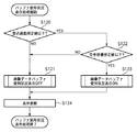
ここで、図3を参照して、S102の画像データバッファの使用状況表示処理の動作について説明する。 Here, with reference to FIG. 3, the operation of the image data buffer usage status display processing in S102 will be described.
S110:システム制御部50は、図2のS101で検出した記録媒体200あるいは210へのデータ書き込み速度を判定し、記録媒体200あるいは210へのデータ書き込み速度が所定値より高い場合は画像データバッファの使用状況表示をOFFし(S111)、記録媒体200あるいは210へのデータ書き込み速度が所定値より低い場合は画像データバッファの使用状況表示をONする(S112)。
S110: The
S113:次に、表示部54の表示を更新し、画像データバッファの使用状況表示処理を終了する。
S113: Next, the display on the
これにより、記録媒体200あるいは210へのデータ書き込み速度が所定値より低い場合のみ、表示部54で画像データバッファの使用状況表示が行われることになる。
Thereby, only when the data writing speed to the
以上が図3に示す画像データバッファの使用状況表示処理である。 The above is the use status display processing of the image data buffer shown in FIG.
図2に戻り説明を続ける。 Returning to FIG.
S103:システム制御部50は、シャッタースイッチ64の操作により静止画像記録が指示されているかどうかを判定する。
S103: The
S104:静止画像記録が指示されている場合、システム制御部50は、処理をS104へ進め、静止画像データをメモリ30に確保された画像データバッファへ格納する(静止画像記録処理)。
S104: When still image recording is instructed, the
画像データバッファに格納された静止画像データは、撮影処理とは独立して、随時、記録媒体200あるいは210へと書き込まれる。
The still image data stored in the image data buffer is written to the
S105:次に、システム制御部50は、動画像の撮影終了が指示されているかどうかを判定し、動画像の撮影終了指示がなければ、処理をS100へと戻し、動画像の撮影処理を継続する。
S105: Next, the
動画像の撮影終了指示があれば、システム制御部50は、動画像の撮影処理を終了する。
If there is a moving image shooting end instruction, the
以上が図2及び図3に示す動画像撮影中に静止画像を記録するための動作である。 The above is the operation for recording a still image during moving image shooting shown in FIGS.
なお、ここでは記録媒体200あるいは210へのデータ書き込み速度が所定値より低い場合に画像データバッファの使用状況表示をONするとして説明を行ったが、判定の基準となるデータ書き込み速度の所定値は、記録中の動画像の記録画素数、圧縮率及びフレームレート、記録しようとする静止画像の記録画素数及び圧縮率、画像データバッファの容量及び使用状況、記録媒体へのデータ書き込み速度等を考慮して決定することが可能である。
Here, the description has been made on the assumption that the display of the usage status of the image data buffer is turned on when the data writing speed to the
[第2の実施形態]
次に、図4を参照して、第2の実施形態の撮像装置の動作について説明する。
[Second Embodiment]
Next, the operation of the imaging apparatus according to the second embodiment will be described with reference to FIG.
図4は、本実施形態の撮像装置100による動画像撮影中に静止画像を記録する際に、画像データバッファの空き容量を考慮に入れた画像データバッファの使用状況表示の動作を示すフローチャートである。
FIG. 4 is a flowchart showing the operation of displaying the usage status of the image data buffer taking into account the free space of the image data buffer when recording a still image during moving image shooting by the
図4を参照して、撮像装置100による動画像撮影中に静止画像を記録する際に、画像データバッファの空き容量を考慮に入れた画像データバッファの使用状況表示の動作について説明する。
With reference to FIG. 4, the operation of displaying the usage status of the image data buffer taking into account the free space of the image data buffer when recording a still image during moving image shooting by the
S120:システム制御部50は、ステップ120にて、図2のS101で検出した記録媒体200あるいは210へのデータ書き込み速度を判定し、記録媒体200あるいは210へのデータ書き込み速度が所定値より高い場合は画像データバッファの使用状況表示をOFFし(S121)、記録媒体200あるいは210へのデータ書き込み速度が所定値より低い場合は処理をS122へ進める。
S120: The
S122:システム制御部50は、画像データバッファの空き容量が所定値より多い場合は画像データバッファの使用状況表示をOFFし(S121)、画像データバッファの空き容量が所定値より少ない場合は画像データバッファの使用状況表示をONする(S123)。
S122: The
S124:次に、表示部54の表示を更新し、画像データバッファの使用状況表示処理を終了する。
S124: Next, the display on the
これにより、記録媒体200あるいは210へのデータ書き込み速度が所定値より低い場合で、かつ画像データバッファの空き容量が所定値より少ない場合のみ、表示部54で画像データバッファの使用状況表示が行われることになる。これは、言い換えると、データ書き込み速度が所定値以上である場合、又はデータ書き込み速度が所定値より低い場合であっても画像データバッファの空き容量が所定値より大きいならば、画像データバッファの使用状況の表示を行わないことにもなる。
Thereby, only when the data writing speed to the
以上が、撮像装置100による動画像撮影中に静止画像を記録する際に、画像データバッファの空き容量を考慮に入れた画像データバッファの使用状況表示の動作である。
The above is the operation of displaying the usage status of the image data buffer in consideration of the free space of the image data buffer when recording a still image during moving image shooting by the
なお、ここでは画像データバッファの空き容量が所定値より少ない場合に画像データバッファの使用状況表示をONするとして説明を行ったが、判定の基準となる画像データバッファの空き容量の所定値は、記録中の動画像の記録画素数、圧縮率及びフレームレート、記録しようとする静止画像の記録画素数及び圧縮率、画像データバッファの容量及び使用状況、記録媒体へのデータ書き込み速度等を考慮して決定することが可能である。 Here, the description has been made on the assumption that the image data buffer usage status display is turned ON when the free space of the image data buffer is smaller than a predetermined value. However, the predetermined value of the free space of the image data buffer serving as a reference for determination is Consider the number of recorded pixels of moving images, the compression rate and frame rate, the number of recorded pixels and compression rate of the still image to be recorded, the capacity and usage of the image data buffer, the data writing speed to the recording medium, etc. Can be determined.
以上説明したように、本実施形態によれば、データ書き込み速度が遅い場合、又はデータ書き込み速度が遅い場合且つ画像データバッファの空き容量が小さい場合であって、画像データバッファの記憶領域が消費されやすくなるような注意を喚起すべき状況でのみ、ユーザに対して画像データバッファの使用状況を分かりやすく通知することができる。 As described above, according to the present embodiment, when the data writing speed is slow, or when the data writing speed is slow and the free space of the image data buffer is small, the storage area of the image data buffer is consumed. Only in situations where it is necessary to call attention so as to facilitate, it is possible to notify the user of the usage status of the image data buffer in an easy-to-understand manner.
[他の実施形態]
以上、本発明に係る実施形態について具体例を用いて詳述したが、本発明は、例えば、システム、装置、方法、プログラム若しくは記憶媒体(記録媒体)等としての実施態様をとることが可能であり、具体的には、複数の機器から構成されるシステムに適用しても良いし、また、一つの機器からなる装置に適用しても良い。
[Other Embodiments]
The embodiment according to the present invention has been described in detail using specific examples. However, the present invention can take an embodiment as a system, apparatus, method, program, storage medium (recording medium), or the like. Specifically, the present invention may be applied to a system composed of a plurality of devices, or may be applied to an apparatus composed of a single device.
尚、本発明は、前述した実施形態の機能を実現するソフトウェアのプログラム(実施形態では図示の各フローチャートに対応したプログラム)を、システムあるいは装置に直接あるいは遠隔から供給し、そのシステムあるいは装置のコンピュータが該供給されたプログラムコードを読み出して実行することによっても達成される場合を含む。 In the present invention, a software program (in the embodiment, a program corresponding to each flowchart shown in the drawings) for realizing the functions of the above-described embodiment is directly or remotely supplied to the system or apparatus, and the computer of the system or apparatus is provided. Is also achieved by reading and executing the supplied program code.
従って、本発明の機能処理をコンピュータで実現するために、該コンピュータにインストールされるプログラムコード自体も本発明を実現するものである。つまり、本発明は、本発明の機能処理を実現するためのコンピュータプログラム自体も含まれる。 Accordingly, since the functions of the present invention are implemented by computer, the program code installed in the computer also implements the present invention. In other words, the present invention includes a computer program itself for realizing the functional processing of the present invention.
その場合、プログラムの機能を有していれば、オブジェクトコード、インタプリタにより実行されるプログラム、OSに供給するスクリプトデータ等の形態であっても良い。 In that case, as long as it has the function of a program, it may be in the form of object code, a program executed by an interpreter, script data supplied to the OS, or the like.
プログラムを供給するための記録媒体(記憶媒体)としては、例えば、フロッピー(登録商標)ディスク、ハードディスク、光ディスク、光磁気ディスク、MO、CD−ROM、CD−R、CD−RW、磁気テープ、不揮発性のメモリカード、ROM、DVD(DVD−ROM,DVD−R)などがある。 As a recording medium (storage medium) for supplying the program, for example, a floppy (registered trademark) disk, hard disk, optical disk, magneto-optical disk, MO, CD-ROM, CD-R, CD-RW, magnetic tape, non-volatile Memory cards, ROM, DVD (DVD-ROM, DVD-R), and the like.
その他、プログラムの供給方法としては、クライアントコンピュータのブラウザを用いてインターネットのホームページに接続し、該ホームページから本発明のコンピュータプログラムそのもの、もしくは圧縮され自動インストール機能を含むファイルをハードディスク等の記録媒体にダウンロードすることによっても供給できる。また、本発明のプログラムを構成するプログラムコードを複数のファイルに分割し、それぞれのファイルを異なるホームページからダウンロードすることによっても実現可能である。つまり、本発明の機能処理をコンピュータで実現するためのプログラムファイルを複数のユーザに対してダウンロードさせるWWWサーバも、本発明に含まれるものである。 As another program supply method, a client computer browser is used to connect to an Internet homepage, and the computer program of the present invention itself or a compressed file including an automatic installation function is downloaded from the homepage to a recording medium such as a hard disk. Can also be supplied. It can also be realized by dividing the program code constituting the program of the present invention into a plurality of files and downloading each file from a different homepage. That is, a WWW server that allows a plurality of users to download a program file for realizing the functional processing of the present invention on a computer is also included in the present invention.
また、本発明のプログラムを暗号化してCD−ROM等の記憶媒体に格納してユーザに配布し、所定の条件をクリアしたユーザに対し、インターネットを介してホームページから暗号化を解く鍵情報をダウンロードさせ、その鍵情報を使用することにより暗号化されたプログラムを実行してコンピュータにインストールさせて実現することも可能である。 In addition, the program of the present invention is encrypted, stored in a storage medium such as a CD-ROM, distributed to users, and key information for decryption is downloaded from a homepage via the Internet to users who have cleared predetermined conditions. It is also possible to execute the encrypted program by using the key information and install the program on a computer.
また、コンピュータが、読み出したプログラムを実行することによって、前述した実施形態の機能が実現される他、そのプログラムの指示に基づき、コンピュータ上で稼動しているOSなどが、実際の処理の一部または全部を行い、その処理によっても前述した実施形態の機能が実現され得る。 In addition to the functions of the above-described embodiments being realized by the computer executing the read program, the OS running on the computer based on the instruction of the program is a part of the actual processing. Alternatively, the functions of the above-described embodiment can be realized by performing all of them and performing the processing.
さらに、記録媒体から読み出されたプログラムが、コンピュータに挿入された機能拡張ボードやコンピュータに接続された機能拡張ユニットに備わるメモリに書き込まれた後、そのプログラムの指示に基づき、その機能拡張ボードや機能拡張ユニットに備わるCPUなどが実際の処理の一部または全部を行い、その処理によっても前述した実施形態の機能が実現される。 Furthermore, after the program read from the recording medium is written in a memory provided in a function expansion board inserted into the computer or a function expansion unit connected to the computer, the function expansion board or The CPU or the like provided in the function expansion unit performs part or all of the actual processing, and the functions of the above-described embodiments are realized by the processing.
10 撮影レンズ
12 シャッター
14 撮像素子
16 A/D変換部
18 タイミング発生部
20 画像処理部
22 メモリ制御部
24 画像表示メモリ
26 D/A変換器
28 画像表示部
30 メモリ
32 画像圧縮・伸長部
40 露光制御部
42 測距制御部
44 ズーム制御部
46 バリア制御部
48 ストロボ
50 システム制御部
52 メモリ
54 表示部
56 不揮発性メモリ
60 モードダイアル
62 シャッタースイッチSW1
64 シャッタースイッチSW2
66 姿勢検出部
70 操作部
80 電源制御部
82,84,92,96 コネクタ
86 電源部
90,94 インターフェース
98 記録媒体着脱検知部
100 撮像装置
102 保護部
110 通信部
112 コネクタ(又はアンテナ)
200,210 記録媒体
202,212 記録部
204,214 インターフェース
206,216 コネクタ
DESCRIPTION OF
64 Shutter switch SW2
66 posture detection unit 70 operation unit 80 power
200, 210 Recording medium 202, 212
Claims (16)
撮影された動画像データおよび動画像撮影中に撮影された静止画像データを一時的に記録する記録手段であって、前記動画像データを記録するための記録領域に、前記静止画像データを記録する記録手段と、
前記記録領域に記録されている前記動画像データを記録媒体に書き込む際の動画像データの書き込み速度を検出する検出手段と、
動画像撮影中に、前記検出手段によって前記動画像データの書き込み速度が所定値より低いことを検出した場合、前記記録領域の使用状況を表示する表示手段とを具備することを特徴とする撮像装置。 An imaging device that records a still image during moving image shooting,
Recording means for temporarily recording captured moving image data and still image data captured during moving image recording , and recording the still image data in a recording area for recording the moving image data Recording means ;
Detecting means for detecting a writing speed of moving image data when writing the moving image data recorded in the recording area to a recording medium;
An imaging apparatus comprising: display means for displaying a usage status of the recording area when the detection means detects that the writing speed of the moving image data is lower than a predetermined value during moving image shooting. .
撮影された動画像データおよび動画像撮影中に撮影された静止画像データを一時的に記録する記録手段であって、前記動画像データを記録するための記録領域に、前記静止画像データを記録する記録手段と、
前記記録領域に記録されている前記動画像データを記録媒体に書き込む際の動画像データの書き込み速度を検出する検出手段と、
動画像撮影中に、前記検出手段によって前記動画像データの書き込み速度が所定値より低いことを検出した場合、前記記録領域の使用状況を表示する表示手段とを具備し、
前記表示手段は、動画像撮影中に、前記動画像データの書き込み速度が前記所定値以上である場合、又は前記動画像データの書き込み速度が前記所定値より低い場合であっても前記記録領域の空き容量が所定容量より大きいならば、前記記録領域の使用状況の表示を行わないことを特徴とする撮像装置。 An imaging device that records a still image during moving image shooting,
Recording means for temporarily recording captured moving image data and still image data captured during moving image recording , and recording the still image data in a recording area for recording the moving image data Recording means ;
Detecting means for detecting a writing speed of moving image data when writing the moving image data recorded in the recording area to a recording medium;
A display unit that displays a usage status of the recording area when the detection unit detects that the writing speed of the moving image data is lower than a predetermined value during moving image shooting;
In the recording area , even when the moving image data writing speed is equal to or higher than the predetermined value or the moving image data writing speed is lower than the predetermined value during moving image shooting. If the free capacity is larger than a predetermined capacity, the use status of the recording area is not displayed.
撮影された動画像データおよび動画像撮影中に撮影された静止画像データを一時的に記録する記録手段における、前記動画像データを記録するための記録領域に、前記静止画像データを記録する記録工程と、
前記記録領域に記録されている前記動画像データを記録媒体に書き込む際の動画像データの書き込み速度を検出する検出工程と、
動画像撮影中に、前記検出工程によって前記動画像データの書き込み速度が所定値より低いことを検出した場合、前記記録領域の使用状況を表示する表示工程とを備えることを特徴とする撮像方法。 An imaging method for recording a still image during moving image shooting,
A recording step of recording the still image data in a recording area for recording the moving image data in a recording means for temporarily recording the captured moving image data and still image data captured during moving image shooting. When,
A detection step of detecting a writing speed of moving image data when writing the moving image data recorded in the recording area to a recording medium;
An imaging method comprising: a display step of displaying a usage status of the recording area when the detection step detects that the writing speed of the moving image data is lower than a predetermined value during moving image shooting.
撮影された動画像データおよび動画像撮影中に撮影された静止画像データを一時的に記録する記録手段における、前記動画像データを記録するための記録領域に、前記静止画像データを記録する記録工程と、
前記記録領域に記録されている前記動画像データを記録媒体に書き込む際の動画像データの書き込み速度を検出する検出工程と、
動画像撮影中に、前記検出工程によって前記動画像データの書き込み速度が所定値より低いことを検出した場合、前記記録領域の使用状況を表示する表示工程とを備え、
前記表示工程では、動画像撮影中に、前記動画像データの書き込み速度が前記所定値以上である場合、又は前記動画像データの書き込み速度が前記所定値より低い場合であっても前記記録領域の空き容量が所定容量より大きいならば、前記記録領域の使用状況の表示を行わないことを特徴とする撮像方法。 An imaging method for recording a still image during moving image shooting,
A recording step of recording the still image data in a recording area for recording the moving image data in a recording means for temporarily recording the captured moving image data and still image data captured during moving image shooting. When,
A detection step of detecting a writing speed of moving image data when writing the moving image data recorded in the recording area to a recording medium;
A display step of displaying a usage status of the recording area when detecting that the writing speed of the moving image data is lower than a predetermined value during the moving image shooting by the detection step;
In the display step, the moving image photographing, when the write speed of the moving image data is the predetermined value or more, or the even if the write speed of the moving image data is lower than the predetermined value of the recording area If the free space is larger than the predetermined capacity, the use status of the recording area is not displayed.
Priority Applications (1)
| Application Number | Priority Date | Filing Date | Title |
|---|---|---|---|
| JP2005148557A JP4681937B2 (en) | 2005-05-20 | 2005-05-20 | Imaging apparatus and imaging method |
Applications Claiming Priority (1)
| Application Number | Priority Date | Filing Date | Title |
|---|---|---|---|
| JP2005148557A JP4681937B2 (en) | 2005-05-20 | 2005-05-20 | Imaging apparatus and imaging method |
Publications (3)
| Publication Number | Publication Date |
|---|---|
| JP2006325148A JP2006325148A (en) | 2006-11-30 |
| JP2006325148A5 JP2006325148A5 (en) | 2008-06-19 |
| JP4681937B2 true JP4681937B2 (en) | 2011-05-11 |
Family
ID=37544450
Family Applications (1)
| Application Number | Title | Priority Date | Filing Date |
|---|---|---|---|
| JP2005148557A Expired - Fee Related JP4681937B2 (en) | 2005-05-20 | 2005-05-20 | Imaging apparatus and imaging method |
Country Status (1)
| Country | Link |
|---|---|
| JP (1) | JP4681937B2 (en) |
Families Citing this family (4)
| Publication number | Priority date | Publication date | Assignee | Title |
|---|---|---|---|---|
| JP5056370B2 (en) * | 2007-11-22 | 2012-10-24 | ソニー株式会社 | IMAGING DEVICE, IMAGING DEVICE CONTROL METHOD, IMAGING DEVICE CONTROL PROGRAM, DATA PROCESSING DEVICE, DATA PROCESSING METHOD, AND DATA PROCESSING PROGRAM |
| JP2012182730A (en) * | 2011-03-02 | 2012-09-20 | Nikon Corp | Digital camera and program |
| JP7225022B2 (en) | 2019-04-26 | 2023-02-20 | キヤノン株式会社 | Imaging device and display control method |
| JP2022169241A (en) | 2021-04-27 | 2022-11-09 | パナソニックIpマネジメント株式会社 | Imaging device |
Citations (6)
| Publication number | Priority date | Publication date | Assignee | Title |
|---|---|---|---|---|
| JPH09322106A (en) * | 1996-05-31 | 1997-12-12 | Canon Inc | Image pickup recorder |
| JPH10233986A (en) * | 1997-02-21 | 1998-09-02 | Hitachi Ltd | Video signal recorder |
| JP2000152038A (en) * | 1998-11-12 | 2000-05-30 | Nikon Corp | Image pickup device and method and recording medium |
| JP2000278579A (en) * | 1999-03-26 | 2000-10-06 | Canon Inc | Image pickup device and computer-readable storage medium |
| JP2001128105A (en) * | 1999-10-27 | 2001-05-11 | Toshiba Corp | Picture recorder |
| JP2001169227A (en) * | 1999-12-14 | 2001-06-22 | Sanyo Electric Co Ltd | Data recorder |
-
2005
- 2005-05-20 JP JP2005148557A patent/JP4681937B2/en not_active Expired - Fee Related
Patent Citations (6)
| Publication number | Priority date | Publication date | Assignee | Title |
|---|---|---|---|---|
| JPH09322106A (en) * | 1996-05-31 | 1997-12-12 | Canon Inc | Image pickup recorder |
| JPH10233986A (en) * | 1997-02-21 | 1998-09-02 | Hitachi Ltd | Video signal recorder |
| JP2000152038A (en) * | 1998-11-12 | 2000-05-30 | Nikon Corp | Image pickup device and method and recording medium |
| JP2000278579A (en) * | 1999-03-26 | 2000-10-06 | Canon Inc | Image pickup device and computer-readable storage medium |
| JP2001128105A (en) * | 1999-10-27 | 2001-05-11 | Toshiba Corp | Picture recorder |
| JP2001169227A (en) * | 1999-12-14 | 2001-06-22 | Sanyo Electric Co Ltd | Data recorder |
Also Published As
| Publication number | Publication date |
|---|---|
| JP2006325148A (en) | 2006-11-30 |
Similar Documents
| Publication | Publication Date | Title |
|---|---|---|
| JP4902460B2 (en) | Image processing apparatus, imaging apparatus, and image processing method | |
| JP2008160792A (en) | Electronic camera and control method thereof | |
| JP2008079137A (en) | Image processing apparatus and control method thereof, computer program, and storage medium | |
| JP2007081752A (en) | Imaging apparatus, control method, control program, and storage medium | |
| JP4681937B2 (en) | Imaging apparatus and imaging method | |
| JP4324116B2 (en) | Image processing apparatus, control method therefor, program, and storage medium | |
| JP2006119996A (en) | Battery-driven device and its nonvolatile memory updating method | |
| JP4646725B2 (en) | IMAGING DEVICE AND IMAGING DEVICE CONTROL METHOD | |
| JP4498169B2 (en) | Image processing apparatus and control method thereof | |
| JP5064686B2 (en) | IMAGING DEVICE, CONTROL METHOD FOR THE DEVICE, CONTROL PROGRAM, AND RECORDING MEDIUM | |
| JP4328697B2 (en) | Imaging apparatus and control method thereof | |
| JP2007158604A (en) | Imaging apparatus and its control method | |
| JP2005221771A (en) | Imaging device and function display method | |
| JP4261815B2 (en) | Imaging device | |
| JP2007221272A (en) | Imaging apparatus and method of controlling same | |
| JP2006203689A (en) | Imaging apparatus and control method thereof, program, and storage medium | |
| JP4574426B2 (en) | Data processing apparatus and data processing method | |
| JP2008252373A (en) | Image processor,image processing method and computer program | |
| JP2007214774A (en) | Imaging apparatus | |
| JP2007189524A (en) | Image processor, and image processing method | |
| JP4717762B2 (en) | Image reproducing apparatus, control method for image reproducing apparatus, program, and recording medium | |
| JP4463941B2 (en) | Imaging apparatus and imaging method | |
| JP4701297B2 (en) | Image processing apparatus, method, and recording medium | |
| JP3697215B2 (en) | Imaging device | |
| JP4766706B2 (en) | Image processing apparatus, control method therefor, program, and storage medium |
Legal Events
| Date | Code | Title | Description |
|---|---|---|---|
| A521 | Request for written amendment filed |
Free format text: JAPANESE INTERMEDIATE CODE: A523 Effective date: 20080507 |
|
| A621 | Written request for application examination |
Free format text: JAPANESE INTERMEDIATE CODE: A621 Effective date: 20080507 |
|
| A977 | Report on retrieval |
Free format text: JAPANESE INTERMEDIATE CODE: A971007 Effective date: 20100607 |
|
| A131 | Notification of reasons for refusal |
Free format text: JAPANESE INTERMEDIATE CODE: A131 Effective date: 20100614 |
|
| A521 | Request for written amendment filed |
Free format text: JAPANESE INTERMEDIATE CODE: A523 Effective date: 20100804 |
|
| A521 | Request for written amendment filed |
Free format text: JAPANESE INTERMEDIATE CODE: A523 Effective date: 20100806 |
|
| TRDD | Decision of grant or rejection written | ||
| A01 | Written decision to grant a patent or to grant a registration (utility model) |
Free format text: JAPANESE INTERMEDIATE CODE: A01 Effective date: 20110131 |
|
| A01 | Written decision to grant a patent or to grant a registration (utility model) |
Free format text: JAPANESE INTERMEDIATE CODE: A01 |
|
| A61 | First payment of annual fees (during grant procedure) |
Free format text: JAPANESE INTERMEDIATE CODE: A61 Effective date: 20110207 |
|
| R150 | Certificate of patent or registration of utility model |
Free format text: JAPANESE INTERMEDIATE CODE: R150 |
|
| FPAY | Renewal fee payment (event date is renewal date of database) |
Free format text: PAYMENT UNTIL: 20140210 Year of fee payment: 3 |
|
| LAPS | Cancellation because of no payment of annual fees |