JP4780730B2 - Removal of carbon dioxide from waste streams by simultaneous production of carbonate and / or bicarbonate minerals - Google Patents
Removal of carbon dioxide from waste streams by simultaneous production of carbonate and / or bicarbonate minerals Download PDFInfo
- Publication number
- JP4780730B2 JP4780730B2 JP2007533607A JP2007533607A JP4780730B2 JP 4780730 B2 JP4780730 B2 JP 4780730B2 JP 2007533607 A JP2007533607 A JP 2007533607A JP 2007533607 A JP2007533607 A JP 2007533607A JP 4780730 B2 JP4780730 B2 JP 4780730B2
- Authority
- JP
- Japan
- Prior art keywords
- gas
- energy
- product
- carbonate
- produce
- Prior art date
- Legal status (The legal status is an assumption and is not a legal conclusion. Google has not performed a legal analysis and makes no representation as to the accuracy of the status listed.)
- Active
Links
Images


Classifications
-
- B—PERFORMING OPERATIONS; TRANSPORTING
- B01—PHYSICAL OR CHEMICAL PROCESSES OR APPARATUS IN GENERAL
- B01D—SEPARATION
- B01D53/00—Separation of gases or vapours; Recovering vapours of volatile solvents from gases; Chemical or biological purification of waste gases, e.g. engine exhaust gases, smoke, fumes, flue gases, aerosols
- B01D53/34—Chemical or biological purification of waste gases
- B01D53/46—Removing components of defined structure
- B01D53/62—Carbon oxides
-
- B—PERFORMING OPERATIONS; TRANSPORTING
- B01—PHYSICAL OR CHEMICAL PROCESSES OR APPARATUS IN GENERAL
- B01D—SEPARATION
- B01D53/00—Separation of gases or vapours; Recovering vapours of volatile solvents from gases; Chemical or biological purification of waste gases, e.g. engine exhaust gases, smoke, fumes, flue gases, aerosols
- B01D53/14—Separation of gases or vapours; Recovering vapours of volatile solvents from gases; Chemical or biological purification of waste gases, e.g. engine exhaust gases, smoke, fumes, flue gases, aerosols by absorption
- B01D53/1418—Recovery of products
-
- B—PERFORMING OPERATIONS; TRANSPORTING
- B01—PHYSICAL OR CHEMICAL PROCESSES OR APPARATUS IN GENERAL
- B01D—SEPARATION
- B01D53/00—Separation of gases or vapours; Recovering vapours of volatile solvents from gases; Chemical or biological purification of waste gases, e.g. engine exhaust gases, smoke, fumes, flue gases, aerosols
- B01D53/14—Separation of gases or vapours; Recovering vapours of volatile solvents from gases; Chemical or biological purification of waste gases, e.g. engine exhaust gases, smoke, fumes, flue gases, aerosols by absorption
- B01D53/1456—Removing acid components
- B01D53/1475—Removing carbon dioxide
-
- B—PERFORMING OPERATIONS; TRANSPORTING
- B01—PHYSICAL OR CHEMICAL PROCESSES OR APPARATUS IN GENERAL
- B01D—SEPARATION
- B01D53/00—Separation of gases or vapours; Recovering vapours of volatile solvents from gases; Chemical or biological purification of waste gases, e.g. engine exhaust gases, smoke, fumes, flue gases, aerosols
- B01D53/34—Chemical or biological purification of waste gases
- B01D53/73—After-treatment of removed components
-
- B—PERFORMING OPERATIONS; TRANSPORTING
- B01—PHYSICAL OR CHEMICAL PROCESSES OR APPARATUS IN GENERAL
- B01D—SEPARATION
- B01D53/00—Separation of gases or vapours; Recovering vapours of volatile solvents from gases; Chemical or biological purification of waste gases, e.g. engine exhaust gases, smoke, fumes, flue gases, aerosols
- B01D53/34—Chemical or biological purification of waste gases
- B01D53/96—Regeneration, reactivation or recycling of reactants
- B01D53/965—Regeneration, reactivation or recycling of reactants including an electrochemical process step
-
- C—CHEMISTRY; METALLURGY
- C01—INORGANIC CHEMISTRY
- C01B—NON-METALLIC ELEMENTS; COMPOUNDS THEREOF; METALLOIDS OR COMPOUNDS THEREOF NOT COVERED BY SUBCLASS C01C
- C01B32/00—Carbon; Compounds thereof
- C01B32/60—Preparation of carbonates or bicarbonates in general
-
- C—CHEMISTRY; METALLURGY
- C01—INORGANIC CHEMISTRY
- C01D—COMPOUNDS OF ALKALI METALS, i.e. LITHIUM, SODIUM, POTASSIUM, RUBIDIUM, CAESIUM, OR FRANCIUM
- C01D7/00—Carbonates of sodium, potassium or alkali metals in general
- C01D7/07—Preparation from the hydroxides
-
- C—CHEMISTRY; METALLURGY
- C01—INORGANIC CHEMISTRY
- C01D—COMPOUNDS OF ALKALI METALS, i.e. LITHIUM, SODIUM, POTASSIUM, RUBIDIUM, CAESIUM, OR FRANCIUM
- C01D7/00—Carbonates of sodium, potassium or alkali metals in general
- C01D7/14—Preparation of sesquicarbonates
-
- C—CHEMISTRY; METALLURGY
- C01—INORGANIC CHEMISTRY
- C01F—COMPOUNDS OF THE METALS BERYLLIUM, MAGNESIUM, ALUMINIUM, CALCIUM, STRONTIUM, BARIUM, RADIUM, THORIUM, OR OF THE RARE-EARTH METALS
- C01F1/00—Methods of preparing compounds of the metals beryllium, magnesium, aluminium, calcium, strontium, barium, radium, thorium, or the rare earths, in general
-
- B—PERFORMING OPERATIONS; TRANSPORTING
- B01—PHYSICAL OR CHEMICAL PROCESSES OR APPARATUS IN GENERAL
- B01D—SEPARATION
- B01D2251/00—Reactants
- B01D2251/30—Alkali metal compounds
- B01D2251/304—Alkali metal compounds of sodium
-
- B—PERFORMING OPERATIONS; TRANSPORTING
- B01—PHYSICAL OR CHEMICAL PROCESSES OR APPARATUS IN GENERAL
- B01D—SEPARATION
- B01D2251/00—Reactants
- B01D2251/60—Inorganic bases or salts
- B01D2251/604—Hydroxides
-
- B—PERFORMING OPERATIONS; TRANSPORTING
- B01—PHYSICAL OR CHEMICAL PROCESSES OR APPARATUS IN GENERAL
- B01D—SEPARATION
- B01D2258/00—Sources of waste gases
- B01D2258/02—Other waste gases
- B01D2258/0283—Flue gases
-
- Y—GENERAL TAGGING OF NEW TECHNOLOGICAL DEVELOPMENTS; GENERAL TAGGING OF CROSS-SECTIONAL TECHNOLOGIES SPANNING OVER SEVERAL SECTIONS OF THE IPC; TECHNICAL SUBJECTS COVERED BY FORMER USPC CROSS-REFERENCE ART COLLECTIONS [XRACs] AND DIGESTS
- Y02—TECHNOLOGIES OR APPLICATIONS FOR MITIGATION OR ADAPTATION AGAINST CLIMATE CHANGE
- Y02C—CAPTURE, STORAGE, SEQUESTRATION OR DISPOSAL OF GREENHOUSE GASES [GHG]
- Y02C20/00—Capture or disposal of greenhouse gases
- Y02C20/40—Capture or disposal of greenhouse gases of CO2
-
- Y—GENERAL TAGGING OF NEW TECHNOLOGICAL DEVELOPMENTS; GENERAL TAGGING OF CROSS-SECTIONAL TECHNOLOGIES SPANNING OVER SEVERAL SECTIONS OF THE IPC; TECHNICAL SUBJECTS COVERED BY FORMER USPC CROSS-REFERENCE ART COLLECTIONS [XRACs] AND DIGESTS
- Y02—TECHNOLOGIES OR APPLICATIONS FOR MITIGATION OR ADAPTATION AGAINST CLIMATE CHANGE
- Y02E—REDUCTION OF GREENHOUSE GAS [GHG] EMISSIONS, RELATED TO ENERGY GENERATION, TRANSMISSION OR DISTRIBUTION
- Y02E60/00—Enabling technologies; Technologies with a potential or indirect contribution to GHG emissions mitigation
- Y02E60/30—Hydrogen technology
- Y02E60/50—Fuel cells
-
- Y—GENERAL TAGGING OF NEW TECHNOLOGICAL DEVELOPMENTS; GENERAL TAGGING OF CROSS-SECTIONAL TECHNOLOGIES SPANNING OVER SEVERAL SECTIONS OF THE IPC; TECHNICAL SUBJECTS COVERED BY FORMER USPC CROSS-REFERENCE ART COLLECTIONS [XRACs] AND DIGESTS
- Y02—TECHNOLOGIES OR APPLICATIONS FOR MITIGATION OR ADAPTATION AGAINST CLIMATE CHANGE
- Y02P—CLIMATE CHANGE MITIGATION TECHNOLOGIES IN THE PRODUCTION OR PROCESSING OF GOODS
- Y02P20/00—Technologies relating to chemical industry
- Y02P20/10—Process efficiency
- Y02P20/129—Energy recovery, e.g. by cogeneration, H2recovery or pressure recovery turbines
-
- Y—GENERAL TAGGING OF NEW TECHNOLOGICAL DEVELOPMENTS; GENERAL TAGGING OF CROSS-SECTIONAL TECHNOLOGIES SPANNING OVER SEVERAL SECTIONS OF THE IPC; TECHNICAL SUBJECTS COVERED BY FORMER USPC CROSS-REFERENCE ART COLLECTIONS [XRACs] AND DIGESTS
- Y02—TECHNOLOGIES OR APPLICATIONS FOR MITIGATION OR ADAPTATION AGAINST CLIMATE CHANGE
- Y02P—CLIMATE CHANGE MITIGATION TECHNOLOGIES IN THE PRODUCTION OR PROCESSING OF GOODS
- Y02P20/00—Technologies relating to chemical industry
- Y02P20/10—Process efficiency
- Y02P20/133—Renewable energy sources, e.g. sunlight
-
- Y—GENERAL TAGGING OF NEW TECHNOLOGICAL DEVELOPMENTS; GENERAL TAGGING OF CROSS-SECTIONAL TECHNOLOGIES SPANNING OVER SEVERAL SECTIONS OF THE IPC; TECHNICAL SUBJECTS COVERED BY FORMER USPC CROSS-REFERENCE ART COLLECTIONS [XRACs] AND DIGESTS
- Y02—TECHNOLOGIES OR APPLICATIONS FOR MITIGATION OR ADAPTATION AGAINST CLIMATE CHANGE
- Y02P—CLIMATE CHANGE MITIGATION TECHNOLOGIES IN THE PRODUCTION OR PROCESSING OF GOODS
- Y02P20/00—Technologies relating to chemical industry
- Y02P20/151—Reduction of greenhouse gas [GHG] emissions, e.g. CO2
Description
発明の分野
本発明は一般に、廃棄物流から二酸化炭素およびそれと並行して他の汚染物質を除去する技術分野に関する。より具体的には、本発明は、濃縮された煙道ガス様の流れから二酸化炭素および他の汚染物質を吸収したのち、吸収された任意の偶発的汚染物質を連行し、中和する炭酸塩および/または炭酸水素塩物質を同時生成することによって廃棄物流から二酸化炭素および他の汚染物質を除去することに関する。
The present invention relates generally to the technical field of removing carbon dioxide and other contaminants in parallel with a waste stream. More specifically, the present invention is a carbonate that entrains and neutralizes any incidental contaminants absorbed after absorbing carbon dioxide and other contaminants from a concentrated flue gas-like stream. And / or removal of carbon dioxide and other contaminants from a waste stream by co-generating bicarbonate material.
関連出願の相互参照
本発明は、2005年9月20日に出願された「Removing Carbon Dioxide from Waste Streams through Co-Generation of Synthetic Carbonate Minerals」と題する米国特許仮出願第60/718,906号;2005年1月10日に出願された米国特許仮出願第60/642,698号;および2004年9月23日に出願された米国特許仮出願第60/612,355号の優先権を主張する。上記開示それぞれの文全体(付録を含む)は、放棄されることなく、明確に参照により本明細書に組み入れられる。
CROSS REFERENCE The present invention related application, filed on September 20, 2005 "Removing Carbon Dioxide from Waste Streams through Co -Generation of Synthetic Carbonate Minerals entitled" U.S. Provisional Patent Application No. 60 / 718,906; 2005 1 Claims priority to US Provisional Application No. 60 / 642,698 filed on May 10, and US Provisional Application No. 60 / 612,355 filed September 23, 2004. The entire text (including appendices) of each of the above disclosures is hereby expressly incorporated herein by reference, without disclaimer.
関連技術
過去40年間、工業から空気中への放出物に対し、個人的および商業的な両セクタにおいて相当な国内的および国際的関心がますます向けられている。特に、大気中への太陽熱の滞留に影響して「温室効果」を生じさせる性質を有する温室効果ガスが注目されている。温室効果は、太陽から入ってくる熱が地球の大気および水圏中に捕らえられて、惑星として地球の平均大気温度、海洋温度ならびに他の中間および平均温度尺度を気候変動点以上まで高めるときに生じる;この効果は一般に、地球の熱均衡における作用効果としては一般に意見の一致を見るが、その速度、人類の物質燃焼がそれに影響する程度ならびにその効果の程度、方向および大きさに関しては議論が交わされている。議論の程度にかかわらず、点放出源からCO2(および他の化学物質)を除去するためのコストが十分に小さいならば、そうすることに利益があるということにはだれもが同意見である。
Related Technology Over the past 40 years, considerable domestic and international interest has been directed at industrial and airborne emissions in both the personal and commercial sectors. In particular, greenhouse gases that have the property of producing a “greenhouse effect” by affecting the retention of solar heat in the atmosphere are drawing attention. The greenhouse effect arises when heat coming from the sun is trapped in the Earth's atmosphere and hydrosphere, raising the Earth's average atmospheric temperature, ocean temperature, and other intermediate and average temperature scales above the climate change point as a planet This effect is generally consensus as an effect on the Earth's thermal balance, but there is controversy about its speed, the extent to which mankind's material combustion affects it, and the extent, direction and magnitude of the effect. Has been. Regardless of the extent of discussion, everyone agrees that if the cost to remove CO 2 (and other chemicals) from a point source is small enough, it would be beneficial to do so .
温室効果ガスは主に二酸化炭素でできており、地域の発電所および大規模産業の工場内発電所によって生成されるが、任意の通常の炭素燃焼(たとえば自動車、多雨林皆伐、単純燃焼など)によっても生成され、もっとも集中的な点放出は地球上の発電所で起こっており、そのような固定場所からの削減または除去を、除去技術を実施するのに魅力的な点にしている。エネルギー生産が温室効果ガス放出の主要な原因であるため、種々の手段によって炭素強度を減らし、効率を改善し、発電所煙道ガスからの炭素を隔離する方法が過去30年にわたり集中的に研究されている。 Greenhouse gases are mainly made of carbon dioxide and are produced by local power plants and large industrial in-plant power plants, but any normal carbon combustion (e.g. automobiles, rainforest clearcuts, simple combustion, etc.) ), And the most intensive point emission occurs at power plants on earth, making such reductions or removals from fixed locations an attractive point for implementing removal techniques. Since energy production is a major cause of greenhouse gas emissions, intensive research has been conducted over the last 30 years to reduce carbon intensity, improve efficiency, and sequester carbon from power plant flue gas by various means Has been.
炭素強度を減らすには、非炭素エネルギー源、たとえば原子力発電、水力発電、太陽光発電、地熱および他の電力源を代替的に使用して、排他的な炭素燃焼によって生産される電力の割合を減らすことを伴う。これらの電力生産技術それぞれが全エネルギー生産を増やし続けているが、世界的電力需要の予測量は、これらの方法からのエネルギー生産よりも速い割合で増すと予想される。したがって、非炭素エネルギー源の成長にもかかわらず、炭素温室効果ガス放出は増大すると予想される。 To reduce carbon intensity, non-carbon energy sources such as nuclear power, hydropower, solar power, geothermal and other power sources can be used instead to reduce the proportion of power produced by exclusive carbon combustion. With reducing. While each of these power production technologies continues to increase total energy production, the projected amount of global power demand is expected to increase at a faster rate than energy production from these methods. Thus, carbon greenhouse gas emissions are expected to increase despite the growth of non-carbon energy sources.
効率の改善は一般に、予燃焼、脱炭素、酸素点火燃焼等を介して、まず生成されるCO2の量を減らし、次いですべての潜在的汚染物質を可能な限り完全に酸化させることによって炭素の燃焼を改善する技術を重要視している。また、この技術は、二酸化炭素放出量あたり生産されるエネルギーの量を増して効率を改善する。この分野における長足の進歩は燃焼効率を改善したが、この分野の努力から引き出すことができる改善はもうほとんどない。 Efficiency improvements are generally achieved through pre-combustion, decarbonization, oxy-ignition combustion, etc., first reducing the amount of CO 2 produced and then oxidizing all potential pollutants as completely as possible. Emphasis is placed on technologies that improve combustion. This technology also improves efficiency by increasing the amount of energy produced per carbon dioxide emission. Long-term progress in this area has improved combustion efficiency, but there is little more improvement that can be drawn from efforts in this area.
炭素(初期形態の気体CO2)の隔離の試みが、地質システム、陸上システムまたは海洋システムとして一般に分類することができる多くの異なる技術を生み出した。これらの技術は主に、生成された二酸化炭素を物理的場所に輸送し、その二酸化炭素を地質、土壌または海洋廃棄物処分場に注入することに関する。これらの隔離技術それぞれは、CO2を輸送に備えて下処理し、輸送を達成し、「炭素バンク」への注入を実施するのに多大なコストを伴う。そのようなものとして、これらの技術は一般に、経済的に実現不可能であり、多くの場合、生成された元の炭素よりも多くのエネルギーを消費する。 Attempts to sequester carbon (early form of gaseous CO 2 ) have produced many different technologies that can be generally classified as geological, terrestrial or marine systems. These techniques are primarily concerned with transporting the generated carbon dioxide to a physical location and injecting the carbon dioxide into a geological, soil or marine waste disposal site. Each of these sequestration technologies involves significant costs in preparing CO 2 for transport, achieving transport, and performing “carbon bank” injections. As such, these technologies are generally not economically feasible and often consume more energy than the original carbon produced.
隔離はまた、スクラビング、膜、低廉なO2および水和物を含むいくつかの工業工程を含むことができる。しかし、これらの技術それぞれは、不経済なレベルにまで高められたプラント資本コストによる損失をこうむり、電力費に対するCO2捕捉の効果はべらぼうに高くつく。 Sequestration can also include several industrial processes including scrubbing, membranes, inexpensive O 2 and hydrates. However, each of these technologies suffers from plant capital costs that have been raised to uneconomical levels, and the effect of capturing CO 2 on electricity costs is rather high.
参考に上げた欠点は、すべてを網羅するものとして意図したものではなく、むしろ、廃棄物流から二酸化炭素を除去する公知技術の有効性を損なう傾向にある多くの欠点のうちいくつかである。しかし、ここで挙げた欠点は、当技術分野で見られる方法が全く満足というわけではなく、本開示で記載し、特許請求される技術に対する有意な要望が存在するということを実証するのには十分である。 The drawbacks listed for reference are not intended to be all-inclusive, but rather are some of the many that tend to undermine the effectiveness of known techniques for removing carbon dioxide from waste streams. However, the drawbacks listed here are not entirely satisfactory with the methods found in the art, and to demonstrate that there is a significant need for the technology described and claimed in this disclosure. It is enough.
概要
本発明は、廃棄物流から二酸化炭素を除去する方法および装置を提供し、該方法および装置は上記の課題を解決する。一般に、本発明は、水酸化化合物を使用して炭酸塩および/または炭酸水素塩を形成することによってガス流から二酸化炭素を除去する方法に関する。その後、炭酸塩および/または炭酸水素塩は、任意のいくつかの用途で使用することもできるし、単に捨てることもできる。
SUMMARY The present invention provides a method and apparatus for removing carbon dioxide from a waste stream, which solves the above problems. In general, the present invention relates to a method for removing carbon dioxide from a gas stream by using a hydroxide compound to form carbonates and / or bicarbonates. Thereafter, the carbonate and / or bicarbonate can be used in any of several applications, or simply discarded.
本発明の様々な態様は、廃棄物流から二酸化炭素をろ去するための現行技術を上回る利点を提供する。本発明によって実現可能であるいくつかの潜在的利点は以下を含む。 Various aspects of the present invention provide advantages over current techniques for filtering carbon dioxide from a waste stream. Some potential advantages that can be realized by the present invention include:
炭素を離れた場所に物理的に移す方法とは違い、塩化ナトリウムおよび二酸化炭素からの炭酸ナトリウムおよび/または炭酸水素ナトリウムの合成による工業規模での同時生成は、望ましくない二酸化炭素を電力生産の点で直接的に化学物質に転換して、隔離場所への輸送コストを潜在的になくす。 Unlike the physical transfer of carbon to a remote location, the simultaneous production of sodium carbonate and / or sodium bicarbonate from sodium chloride and carbon dioxide on an industrial scale results in the production of undesirable carbon dioxide for power production. Directly convert to chemicals, potentially eliminating the cost of transportation to isolation.
レトロフィットに適さない煙道ガス流の脱炭酸塩化における他の試みとは違い、本発明の態様は、既存の発電所にレトロフィットさせて、脱炭酸塩処理を実現するのに必要な資本コストを大幅に下げることができる。さらには、脱炭酸塩処理は、スケーリング可能であり、増分リアクタユニットの追加によってパイロットないし中間ないしフルスケールの態様によって具現化することができる。 Unlike other attempts in decarbonation of flue gas streams that are not suitable for retrofit, aspects of the present invention provide the cost of capital required to retrofit existing power plants to achieve decarboxylation. Can be greatly reduced. Furthermore, the decarboxylation process is scalable and can be implemented in a pilot to intermediate to full scale manner with the addition of incremental reactor units.
当技術分野における他の方法とは違い、特定の態様の脱炭酸塩化工程は、二酸化炭素を経済的に有用な化学物質へと隔離し、有用な副生成物、たとえば塩素ガス、炭酸ナトリウムおよび水素ガスを同時に製造する。脱炭酸塩化工程の副生成物は経済的に有用であるため、それらの価値が隔離コストを相殺し、適切に設計されたシステムでは、隔離工程そのものを収益性にする可能性がある。 Unlike other methods in the art, certain embodiments of the decarboxylation process sequester carbon dioxide into economically useful chemicals and use by-products such as chlorine gas, sodium carbonate and hydrogen. Gas is produced at the same time. Because by-products of the decarbonation process are economically useful, their value offsets the cost of sequestration, and in a properly designed system, the sequestration process itself can be profitable.
放出された煙道ガスの攻撃的なスクラビングの同時工程のおかげで、他の望ましくはい酸性汚染物質、たとえばSOx、NOx、HgOx等が工程中で攻撃的にスクラビングされる。さらには、スクラビング工程は、他のガス流成分および汚染物質(たとえば石炭からの灰分など)を炭酸ナトリウム中に閉じ込めおよび/または連行して、それにより、ガス流からそれらを除去することができる。 Thanks to the simultaneous process of aggressive scrubbing of the emitted flue gas, other desirable acidic pollutants such as SO x , NO x , HgO x etc. are aggressively scrubbed in the process. Furthermore, the scrubbing process can entrap and / or entrain other gas stream components and contaminants (such as ash from coal) in sodium carbonate, thereby removing them from the gas stream.
本発明の特定の態様は、ガス流から二酸化炭素を除去する方法であって、水酸化物を水性混合物中に得る段階;水酸化物をガス流と混和させて、炭酸塩生成物(炭酸基CO3を含有する生成物と定義する)、炭酸水素塩生成物(炭酸水素基HCO3を含有する生成物と定義する)または炭酸塩生成物と炭酸水素塩生成物との混合物を混和物として製造する段階;ならびに混和物から該炭酸塩生成物および/または炭酸水素塩生成物を分離して、それによってガス流から二酸化炭素を除去する段階を含む方法を含む。水酸化物は、水酸化ナトリウム、水酸化カリウム、水酸化カルシウム、水酸化マグネシウムおよび水酸化アルミニウムをはじめとする、限定されない、いかなる形態の水酸化物であることもできる。当業者は、いかなる数の水酸化物または水酸化物の混合物を用いても同様な化学反応および脱炭酸塩化を得ることが可能であることを理解するであろう。いくつかの好ましい態様では、水酸化物は水酸化ナトリウムである。 A particular aspect of the present invention is a method for removing carbon dioxide from a gas stream comprising obtaining a hydroxide in an aqueous mixture; the hydroxide is mixed with the gas stream to produce a carbonate product (carbonate group). A mixture of a carbonate product and a bicarbonate product (defined as a product containing CO 3 ), a bicarbonate product (defined as a product containing a bicarbonate group HCO 3 ) or a carbonate product. And a method comprising separating the carbonate product and / or bicarbonate product from the blend, thereby removing carbon dioxide from the gas stream. The hydroxide can be any form of hydroxide including but not limited to sodium hydroxide, potassium hydroxide, calcium hydroxide, magnesium hydroxide and aluminum hydroxide. One skilled in the art will appreciate that similar chemical reactions and decarboxylation can be obtained using any number of hydroxides or mixtures of hydroxides. In some preferred embodiments, the hydroxide is sodium hydroxide.
特定の態様では、方法は、実質的に炭酸塩生成物のみ、または実質的に炭酸水素塩生成物のみを製造するように方法をプロセス制御することをさらに含む。他の態様では、方法は、炭酸塩約X%および炭酸水素塩約Y%で構成されることができる、炭酸塩生成物と炭酸水素塩生成物との混合物を製造するように方法をプロセス制御することをさらに含み、X-Yの組み合わせは、以下のいずれかである:1-99、2-98、3-97、4-96、5-95、6-94、7-93、8-92、9-91、10-90、15-85、20-80、25-75、30-70、35-65、40-60、45-55、50-50、55-45、60-40、65-35、70-30、75-25、80-20、85-15、90-10、91-9、92-8、93-7、94-6、95-5、96-4、97-3、98-2または99-1。 In certain aspects, the method further comprises process controlling the method to produce substantially only the carbonate product, or substantially only the bicarbonate product. In other embodiments, the process controls the process to produce a mixture of a carbonate product and a bicarbonate product, wherein the method can be comprised of about X% carbonate and about Y% bicarbonate. And the combination of XY is any of the following: 1-99, 2-98, 3-97, 4-96, 5-95, 6-94, 7-93, 8-92, 9-91, 10-90, 15-85, 20-80, 25-75, 30-70, 35-65, 40-60, 45-55, 50-50, 55-45, 60-40, 65- 35, 70-30, 75-25, 80-20, 85-15, 90-10, 91-9, 92-8, 93-7, 94-6, 95-5, 96-4, 97-3, 98-2 or 99-1.
特定の態様では、混和は二つの別々のチャンバで起こり、一方のチャンバは、炭酸塩生成物を製造するために使用され、他方のチャンバは、炭酸水素塩生成物を製造するために使用される。他の態様では、混和は、バブルカラムまたは一連のバブルカラムで起こる。さらに別の態様では、混和物からの炭酸塩生成物および/または炭酸水素塩生成物の分離は加熱沈殿分離工程を含む。いくつかの態様では、分離工程のための熱は、入ってくる煙道ガスとの熱交換から導出される。分離された炭酸塩は、水性スラリーの形態にあることもできるし、または分離の時点で様々な濃度にある水酸化物、炭酸塩および水の溶液としての形態にあることもでき、その場合には、多くの方法のいずれかによって乾燥させることができる。いくつかの態様では、炭酸塩を乾燥させる必要はない。たとえば、炭酸ナトリウムのスラリーは硬水の処理に使用することができる。当然、当業者は、本発明の方法によって製造された炭酸塩を付すことができる多様な用途を知るであろう。たとえば、炭酸水素ナトリウムと炭酸ナトリウムとのスラリー混合物は、様々な形態の洗浄剤製造における使用、ガラス製造における融剤等としての使用ならびに前述の水処理用途に備えてタンク車にスラリー化することができる。 In certain embodiments, blending occurs in two separate chambers, one chamber is used to produce a carbonate product and the other chamber is used to produce a bicarbonate product. . In other embodiments, the mixing occurs in a bubble column or a series of bubble columns. In yet another aspect, separation of the carbonate product and / or bicarbonate product from the blend includes a heat precipitation separation step. In some embodiments, the heat for the separation process is derived from heat exchange with the incoming flue gas. The separated carbonate can be in the form of an aqueous slurry or in the form of a solution of hydroxide, carbonate and water at various concentrations at the time of separation, in which case Can be dried by any of a number of methods. In some embodiments, the carbonate need not be dried. For example, a sodium carbonate slurry can be used to treat hard water. Of course, those skilled in the art will know the various applications in which the carbonates produced by the process of the present invention can be applied. For example, a slurry mixture of sodium bicarbonate and sodium carbonate can be slurried in tank trucks for use in various forms of detergent manufacture, as a flux in glass manufacture, and for the aforementioned water treatment applications. it can.
特定の態様では、方法は、炭酸塩生成物を離れた隔離場所に輸送する段階;炭酸塩生成物を酸と合わせて中和反応させて純粋な二酸化炭素を生成する段階;および二酸化炭素を炭素バンクに注入する段階をさらに含む。他の態様では、SOx、NOx、および水銀含有物質をはじめとするガス流の他の成分を炭酸塩形成工程で中和および/または連行/捕捉する。 In certain embodiments, the method includes transporting the carbonate product to a remote sequestration site; neutralizing the carbonate product with an acid to produce pure carbon dioxide; and carbon dioxide to carbon The method further includes injecting into the bank. In other embodiments, SO x , NO x , and other components of the gas stream, including mercury-containing materials, are neutralized and / or entrained / trapped in the carbonate formation step.
いくつかの態様では、水酸化物を得ることは、塩を得る段階;塩を水、蒸気、または両方と混和させて溶液を製造する段階;および溶液を電気分解して水酸化物を製造する段階を含む。特定の態様では、溶液は、約5ボルトより大きいかまたは等しい電圧を使用して電気分解し、他の態様では、溶液は、約5ボルト未満の電圧を使用して電気分解する。いくつかの態様では、溶液は、1ボルト〜5ボルトの電圧、たとえば約1.5ボルト、約2.0ボルト、約2.5ボルト、約3.0ボルト、約3.5ボルト、約4.0ボルトもしくは約4.5ボルトまたはこれらの点のいずれかの間で導出可能な範囲の電圧を使用して電気分解する。 In some embodiments, obtaining a hydroxide includes obtaining a salt; mixing the salt with water, steam, or both to produce a solution; and electrolyzing the solution to produce a hydroxide. Including stages. In certain embodiments, the solution is electrolyzed using a voltage greater than or equal to about 5 volts, and in other embodiments, the solution is electrolyzed using a voltage less than about 5 volts. In some embodiments, the solution is at a voltage between 1 volt and 5 volts, such as about 1.5 volts, about 2.0 volts, about 2.5 volts, about 3.0 volts, about 3.5 volts, about 4.0 volts or about 4.5 volts or at these points. Electrolysis is performed using a voltage that can be derived between the two.
特定の態様では、溶液を電気分解する前に酸を溶液に加える。酸は、塩酸をはじめとして、溶液にプロトン化を提供することができる、限定されない、いかなる形態の酸であってもよい。当業者は、いかなる数の酸または酸の混合物を用いても同様な化学反応および電気分解を得ることが可能であることを理解するであろう。いくつかの好ましい態様では、酸は塩酸である。他の態様では、溶液に加える酸の量は、反応体を製造するための最低エネルギーおよび生成物から回収する最高エネルギーを達成する最適なプロトン化率の決定に基づく。 In certain embodiments, the acid is added to the solution prior to electrolyzing the solution. The acid can be any form of acid, including but not limited to hydrochloric acid, that can provide protonation to the solution. One skilled in the art will appreciate that similar chemical reactions and electrolysis can be obtained using any number of acids or mixtures of acids. In some preferred embodiments, the acid is hydrochloric acid. In other embodiments, the amount of acid added to the solution is based on the determination of the optimal protonation rate that achieves the lowest energy to produce the reactants and the highest energy recovered from the product.
さらに他の態様では、電気分解工程は、陰極液側および陽極液側を有する電気化学セル中で起こり、かつ炭酸塩生成物および/または炭酸水素塩生成物は電気化学セルの陰極液側にリサイクルされる。他の態様では、方法に必要なエネルギーは、ガス流からの回収される廃熱によって補充される。 In yet another aspect, the electrolysis step occurs in an electrochemical cell having a catholyte side and an anolyte side, and the carbonate product and / or bicarbonate product is recycled to the catholyte side of the electrochemical cell. Is done. In other embodiments, the energy required for the process is supplemented by recovered waste heat from the gas stream.
本発明の他の態様は、ガス流から二酸化炭素を除去する方法であって、水酸化ナトリウムを水性混合物中に得る段階;水酸化ナトリウムをガス流と混和させて、炭酸ナトリウム、炭酸水素ナトリウム、または炭酸ナトリウムと炭酸水素ナトリウムとの混合物を製造する段階;および混和物から該炭酸ナトリウムおよび/または炭酸水素ナトリウムを分離して、それによってガス流から二酸化炭素を除去する段階を含む方法を含む。 Another aspect of the invention is a method for removing carbon dioxide from a gas stream, wherein sodium hydroxide is obtained in an aqueous mixture; sodium hydroxide is mixed with the gas stream to form sodium carbonate, sodium bicarbonate, Or producing a mixture of sodium carbonate and sodium bicarbonate; and separating the sodium carbonate and / or sodium bicarbonate from the blend, thereby removing carbon dioxide from the gas stream.
いくつかの態様では、方法は、実質的に炭酸ナトリウムのみ、または実質的に炭酸水素ナトリウムのみを製造するように方法をプロセス制御することをさらに含む。他の態様では、方法は、炭酸ナトリウム約X%および炭酸水素ナトリウム約Y%で構成されることができる、炭酸ナトリウムと炭酸水素ナトリウムとの混合物を製造するように方法をプロセス制御することをさらに含み、X-Yの組み合わせは、以下のいずれかである:1-99、2-98、3-97、4-96、5-95、6-94、7-93、8-92、9-91、10-90、15-85、20-80、25-75、30-70、35-65、40-60、45-55、50-50、55-45、60-40、65-35、70-30、75-25、80-20、85-15、90-10、91-9、92-8、93-7、94-6、95-5、96-4、97-3、98-2または99-1。 In some embodiments, the method further comprises process controlling the method to produce substantially only sodium carbonate, or substantially only sodium bicarbonate. In other embodiments, the method further comprises process controlling the method to produce a mixture of sodium carbonate and sodium bicarbonate, which can be comprised of about X% sodium carbonate and about Y% sodium bicarbonate. And the combination of XY is any of the following: 1-99, 2-98, 3-97, 4-96, 5-95, 6-94, 7-93, 8-92, 9-91, 10-90, 15-85, 20-80, 25-75, 30-70, 35-65, 40-60, 45-55, 50-50, 55-45, 60-40, 65-35, 70- 30, 75-25, 80-20, 85-15, 90-10, 91-9, 92-8, 93-7, 94-6, 95-5, 96-4, 97-3, 98-2 or 99-1.
特定の態様では、混和は二つの別々のチャンバで起こり、一方のチャンバは、炭酸ナトリウムを製造するために使用され、他方のチャンバは、炭酸水素ナトリウムを製造するために使用される。他の態様では、混和は、バブルカラムまたは一連のバブルカラムで起こる。さらに別の態様では、混和物からの炭酸ナトリウムおよび/または炭酸水素ナトリウムの分離は加熱沈殿分離工程を含む。いくつかの態様では、分離工程のための熱は、入ってくる煙道ガスとの熱交換から導出される。 In certain embodiments, blending occurs in two separate chambers, one chamber is used to produce sodium carbonate and the other chamber is used to produce sodium bicarbonate. In other embodiments, the mixing occurs in a bubble column or a series of bubble columns. In yet another embodiment, the separation of sodium carbonate and / or sodium bicarbonate from the blend includes a heat precipitation separation step. In some embodiments, the heat for the separation process is derived from heat exchange with the incoming flue gas.
特定の態様では、方法は、炭酸ナトリウムを離れた隔離場所に輸送する段階;炭酸塩生成物を酸と合わせて中和反応させて純粋な二酸化炭素を生成する段階;および二酸化炭素を炭素バンクに注入することをさらに含む。 In certain embodiments, the method includes transporting sodium carbonate to a remote sequestration site; neutralizing the carbonate product with an acid to produce pure carbon dioxide; and carbon dioxide to a carbon bank. Injecting further.
いくつかの態様では、水酸化ナトリウムを得ることは、塩化ナトリウムを得る段階;塩化ナトリウムを水、蒸気、または両方と混和させてブラインを製造する段階;およびブラインを電気分解して水酸化ナトリウムおよび塩素ガスを製造する段階を含む。特定の態様では、ブラインは、約5ボルトより大きいかまたは等しい電圧を使用して電気分解し、他の態様では、約5ボルト未満の電圧を使用して電気分解する。いくつかの態様では、溶液は、1ボルト〜5ボルトの電圧、たとえば約1.5ボルト、約2.0ボルト、約2.5ボルト、約3.0ボルト、約3.5ボルト、約4.0ボルトもしくは約4.5ボルトまたはこれらの点のいずれかの間で導出可能な範囲の電圧を使用して電気分解する。 In some embodiments, obtaining sodium hydroxide includes obtaining sodium chloride; mixing sodium chloride with water, steam, or both to produce brine; and electrolyzing the brine with sodium hydroxide and Including the step of producing chlorine gas. In certain embodiments, the brine is electrolyzed using a voltage greater than or equal to about 5 volts, and in other embodiments, the brine is electrolyzed using a voltage less than about 5 volts. In some embodiments, the solution is at a voltage between 1 volt and 5 volts, such as about 1.5 volts, about 2.0 volts, about 2.5 volts, about 3.0 volts, about 3.5 volts, about 4.0 volts or about 4.5 volts or at these points. Electrolysis is performed using a voltage that can be derived between the two.
いくつかの態様では、ブラインを電気分解する前に酸をブラインに加える。酸は、塩酸をはじめとして、溶液にプロトン化を提供することができる、限定されない、いかなる形態の酸であってもよい。当業者は、いかなる数の酸または酸の混合物を用いても同様な化学反応および電気分解を得ることが可能であることを理解するであろう。いくつかの好ましい態様では、酸は塩酸である。他の態様では、ブラインに加える酸の量は、反応体を製造するための最低エネルギーおよび生成物から回収する最高エネルギーを達成する最適なプロトン化率の決定に基づく。 In some embodiments, the acid is added to the brine before electrolyzing the brine. The acid can be any form of acid, including but not limited to hydrochloric acid, that can provide protonation to the solution. One skilled in the art will appreciate that similar chemical reactions and electrolysis can be obtained using any number of acids or mixtures of acids. In some preferred embodiments, the acid is hydrochloric acid. In other embodiments, the amount of acid added to the brine is based on determining an optimal protonation rate that achieves the lowest energy to produce the reactants and the highest energy recovered from the product.
特定の態様では、電気分解工程は、陰極液側および陽極液側を有する電気化学セル中で起こり、炭酸ナトリウムおよび/または炭酸水素ナトリウムが電気化学セルの陰極液側にリサイクルされる。他の態様では、方法に必要なエネルギーは、ガス流から回収される廃熱によって補充される。さらに他の態様では、方法は、塩素ガスを収集することをさらに含み、他の態様では、水素ガスを製造する。いくつかの態様では、水素ガスおよび塩素ガスを燃焼させて塩酸を形成し、ブラインを電気分解する前に塩酸をブラインに加える。他の態様では、水素ガスを大気酸素または原料薬品からの酸素とで燃焼させて水を製造し、他の態様では、方法は、水素ガスを使用してエネルギーを生産することを含む。いくつかの態様では、混和物からの炭酸ナトリウムおよび/または炭酸水素ナトリウムの分離は、分離工程のための熱を水素ガスによって生産されるエネルギーから導出する加熱沈殿分離工程を含む。他の態様では、水素ガスを石炭とで同時燃焼させて石炭燃焼放出を改善するか、それを、直流電気の燃料セル回収のために燃焼工程で使用する。 In certain embodiments, the electrolysis step occurs in an electrochemical cell having a catholyte side and an anolyte side, and sodium carbonate and / or sodium bicarbonate is recycled to the catholyte side of the electrochemical cell. In other embodiments, the energy required for the process is supplemented by waste heat recovered from the gas stream. In yet another aspect, the method further includes collecting chlorine gas, and in another aspect, producing hydrogen gas. In some embodiments, hydrogen gas and chlorine gas are combusted to form hydrochloric acid, and hydrochloric acid is added to the brine before electrolyzing the brine. In other embodiments, hydrogen gas is combusted with atmospheric oxygen or oxygen from source chemicals to produce water, and in other embodiments, the method includes using hydrogen gas to produce energy. In some embodiments, the separation of sodium carbonate and / or sodium bicarbonate from the blend includes a heat precipitation separation step that derives heat for the separation step from the energy produced by the hydrogen gas. In other embodiments, hydrogen gas is co-combusted with coal to improve coal combustion emissions, or it is used in the combustion process for direct current fuel cell recovery.
いくつかの態様では、ガス流は、プラントからの排気流であり、他の態様では、プラントは、炭素系燃料源を使用する発電所である。特定の態様では、排気流はCO2およびH2Oを含む。 In some aspects, the gas stream is an exhaust stream from the plant, and in other aspects the plant is a power plant that uses a carbon-based fuel source. In certain embodiments, the exhaust stream comprises CO 2 and H 2 O.
また、本発明の特定の態様は、少なくとも一つの陰極および少なくとも一つの陽極を含み、使用中に水酸化物を製造するように適合されている電気分解チャンバ;電気分解チャンバおよび使用中にガス流を含むように適合されている導管に作動可能に接続されており、電気分解チャンバからの水酸化物をガス流と混和させて、ガス流中の炭素、硫黄、および/または窒素化合物が水酸化物と反応することができるところの混和物を形成するように適合されている混合機;ならびに混合機に作動可能に接続され、混和物を別々の気相と固相および/または液相とに分離するように適合されている分離チャンバを含む、装置を含む。 Also, certain embodiments of the present invention include an electrolysis chamber that includes at least one cathode and at least one anode and is adapted to produce hydroxide during use; the electrolysis chamber and gas flow during use And is operably connected to a conduit adapted to contain, and the hydroxide from the electrolysis chamber is mixed with the gas stream so that the carbon, sulfur, and / or nitrogen compounds in the gas stream are hydroxylated. A mixer adapted to form an admixture that can react with the product; and operably connected to the mixer to separate the admixture into separate gas phases and solid and / or liquid phases An apparatus comprising a separation chamber adapted to separate.
いくつかの態様では、電気分解チャンバは膜セル、隔膜、および/または水銀を含む。特定の態様では、混合機はバッチリアクタまたは一連のバッチリアクタであり、他の態様では、混合チャンバは気/液吸収/反応機器または一連の気/液吸収/反応機器である。他の態様では、混合チャンバは結晶化塔(crystallization tower)または一連の結晶化塔であり、他の態様では、バブルカラムまたは一連のバブルカラムである。 In some embodiments, the electrolysis chamber includes a membrane cell, a diaphragm, and / or mercury. In certain embodiments, the mixer is a batch reactor or a series of batch reactors, and in other embodiments, the mixing chamber is a gas / liquid absorption / reaction device or a series of gas / liquid absorption / reaction devices. In other embodiments, the mixing chamber is a crystallization tower or series of crystallization towers, and in other embodiments is a bubble column or series of bubble columns.
特定の態様では、装置は、分離チャンバに作動可能に接続され、使用中に固相および/または液相から液体を取り出すように適合された乾燥チャンバをさらに含み、他の態様では、乾燥チャンバは、使用中に固相および/または液相を加熱するように適合されている。さらに別の態様では、装置は、発電所に作動可能に接続されているとしてさらに定義される。 In certain aspects, the apparatus further comprises a drying chamber operably connected to the separation chamber and adapted to remove liquid from the solid and / or liquid phase during use, in other aspects the drying chamber is Adapted to heat the solid phase and / or liquid phase during use. In yet another aspect, the device is further defined as being operably connected to the power plant.
いくつかの態様では、電気分解チャンバは、使用中に塩化ナトリウムおよび水から塩素ガスおよび水酸化ナトリウムを製造するように適合されている。他の態様では、混合機は、使用中に電気分解チャンバからの水酸化物をガス流からの二酸化炭素と混和させて炭酸塩生成物および/または炭酸水素塩生成物を製造するように適合されている。 In some embodiments, the electrolysis chamber is adapted to produce chlorine gas and sodium hydroxide from sodium chloride and water during use. In other aspects, the mixer is adapted to mix the hydroxide from the electrolysis chamber with carbon dioxide from the gas stream during use to produce carbonate and / or bicarbonate products. ing.
さらに別の態様では、本発明は、所与のプロトン化における所与のV/I特性に関して、低電圧作動に最適な電気化学セルの作動電圧および電流を面積増に関して決定する方法を含む。他の態様では、本発明は、工程で使用される所与の電気分解セルに関して作動電圧の熱力学的下限を決定する方法を含む。特定の態様では、一般に廃棄物流からCO2を除去する作業を達成する装置に関してエコロジー効率(∂CO2/∂E)を規定する方法が提供され、他の態様は、特に本発明をその態様のいずれかで使用する装置に関してエコロジー効率(∂CO2/∂E)を規定する方法を含む。他の態様は、そのコストが回収可能なエネルギー量に等しい低い価格無差別点できわめて純粋な水素ガスを製造する方法を含む。 In yet another aspect, the present invention includes a method for determining an electrochemical cell operating voltage and current in terms of area gain that is optimal for low voltage operation for a given V / I characteristic in a given protonation. In another aspect, the invention includes a method for determining a thermodynamic lower limit for an operating voltage for a given electrolysis cell used in the process. In certain embodiments, a method is provided for defining ecology efficiency (∂CO 2 / ∂E) for an apparatus that generally accomplishes the task of removing CO 2 from a waste stream, while other embodiments specifically address the present invention. Includes methods to define ecological efficiency (∂CO 2 / ∂E) for equipment used in either. Another aspect includes a method of producing extremely pure hydrogen gas with a low price promiscuous point whose cost is equal to the amount of recoverable energy.
「含む」(および含むの活用形)、「有する」(および有するの活用形)、「含有する」(および含有するの活用形)および「包含する」(および包含するの活用形)は、非限定的な連結動詞である。結果として、一つまたは複数の工程または要素を「含む」、「有する」、「含有する」または「包含する」方法または装置は、一つまたは複数のそのような工程または要素を所有するが、一つまたは複数のそのような工程または要素だけを所有することに限定されない。同様に、一つまたは複数の特徴を「含む」、「有する」、「含有する」または「包含する」装置または方法の要素は、一つまたは複数のそのような特徴を所有するが、一つまたは複数のそのような特徴だけを所有することに限定されない。「使用する」もまた同様に解釈されるべきである。したがって、一例として、特定の情報を「使用する」ことを含む方法の工程は、少なくとも挙げられた情報は使用されるが、他の挙げられていない情報をも使用することができる可能性を排除しないことを意味する。さらには、ある特定の方法で構成されている構造は、少なくともその方法で構成されていなければならないが、指定されていない方法ででも構成されていてもよい。 `` Contains '' (and uses of containing), `` has '' (and uses of having), `` contains '' (and uses of containing) and `` includes '' (and uses of containing) Limited connective verb. As a result, a method or apparatus that “includes”, “haves”, “contains”, or “includes” one or more steps or elements owns one or more such steps or elements, It is not limited to owning only one or more such steps or elements. Similarly, an element of a device or method “including”, “having”, “containing” or “including” one or more features possesses one or more such features, Or it is not limited to possessing only a plurality of such features. “Use” should also be interpreted similarly. Thus, by way of example, a method step that includes “using” specific information eliminates the possibility of using at least the listed information but also other unlisted information. It means not. Furthermore, a structure that is configured in a specific way must be configured at least in that way, but may be configured in a manner that is not specified.
単数形の語は、開示がそうでないことを明示的に要求しない限り、一つまたは一つより多くあるものと定義される。「もう一つの」とは、少なくとも第二以降があるものと定義される。「実質的」および「約」とは、所与の値または状態に少なくとも近い(およびそれを含む)ものと定義される(好ましくは10%以内、より好ましくは1%以内、もっともの好ましくは0.1%以内)。 The singular terms are defined to be one or more than one unless the disclosure explicitly requires otherwise. “Another” is defined as having at least a second or later. `` Substantial '' and `` about '' are defined as being at least close to (and including) a given value or condition (preferably within 10%, more preferably within 1%, most preferably 0.1). Within%).
本明細書で使用する「炭酸塩」または「炭酸塩生成物」という用語は一般に、炭酸基CO3を含有する鉱物成分と定義される。したがって、この語は、炭酸塩/炭酸水素塩混合物および炭酸イオンのみを含有する種の両方を包含する。「炭酸水素塩」および「炭酸水素塩生成物」は一般に、炭酸水素基HCO3を含有する鉱物成分と定義される。したがって、この語は、炭酸塩/炭酸水素塩混合物および炭酸水素イオンのみを含有する種の両方を包含する。 As used herein, the term “carbonate” or “carbonate product” is generally defined as a mineral component containing a carbonate group CO 3 . The term thus encompasses both carbonate / bicarbonate mixtures and species containing only carbonate ions. “Bicarbonate” and “bicarbonate product” are generally defined as mineral components containing the bicarbonate group HCO 3 . Thus, this term encompasses both carbonate / bicarbonate mixtures and species containing only bicarbonate ions.
本発明のいくつかの態様を使用する炭酸水素塩および炭酸塩の形成で、「イオン比」という用語は、生成物中のナトリウムイオンをその生成物中に存在する炭素の数で割った比をいう。したがって、純粋な炭酸水素塩(NaHCO3)で形成された生成物流は、1.0の「イオン比」(Na/C)を有するということができ、純粋な炭酸塩(Na2CO3)で形成された生成物流は、2.0の「イオン比」(Na/C)を有するということができる。拡大解釈すると、無限数の、炭酸塩と炭酸水素塩との連続的混合物が、1.0〜2.0の間で変動するイオン比を有するということができる。 In the formation of bicarbonate and carbonate using some embodiments of the present invention, the term “ion ratio” refers to the ratio of sodium ions in a product divided by the number of carbons present in that product. Say. Thus, the product stream formed with pure bicarbonate (NaHCO 3 ) can be said to have an `` ion ratio '' (Na / C) of 1.0 and formed with pure carbonate (Na 2 CO 3 ). The product stream can be said to have an “ion ratio” (Na / C) of 2.0. By extension, it can be said that an infinite number of continuous mixtures of carbonate and bicarbonate have an ionic ratio that varies between 1.0 and 2.0.
本発明のいくつかの好ましい態様では、塩酸を塩素アルカリ電気分解セルの塩化ナトリウムブライン原料に加えて以下の反応を起こさせる。
H2O+NaCl+aHCl+エネルギー→NaOH+(1/2+a/2)H2+(1/2+a/2)Cl2
この式では、項「a」は「プロトン化係数」と定義され、ナトリウムイオン(Na+イオン)に対するプロトン(H+イオン)の比を表す。
In some preferred embodiments of the present invention, hydrochloric acid is added to the sodium chloride brine feed of the chlor-alkali electrolysis cell to cause the following reaction.
H 2 O + NaCl + aHCl + energy → NaOH + (1/2 + a / 2) H 2 + (1/2 + a / 2) Cl 2
In this equation, the term “a” is defined as “protonation coefficient” and represents the ratio of protons (H + ions) to sodium ions (Na + ions).
本明細書で使用する「隔離」とは、一般に、その部分的または全体的な効果が、CO2を点放出限から除去し、そのCO2を何らかの形態で貯蔵して大気中に戻るのを防ぐことである技術または実施をいうために使用される。この語の使用は、記載される態様の任意の形態が「隔離」技術とみなされることを排除しない。 As used herein, “sequestration” generally refers to the partial or overall effect of removing CO 2 from the point emission limit, storing the CO 2 in some form, and returning it to the atmosphere. Used to refer to a technique or practice that is to prevent. The use of this term does not exclude that any form of the described embodiment is considered a “separation” technique.
本明細書で使用する「エコロジー効率」は、「熱力学的効率」と同義に使用され、消費されるエネルギーあたり本発明の特定の態様によって隔離されるCO2の量(式「∂CO2/∂E」によって表す)と定義される。CO2隔離は、プラント全体のCO2の%に換算して表される。エネルギー消費も同様に、プラント全体の電力消費に換算して表される。 As used herein, “ecological efficiency” is used synonymously with “thermodynamic efficiency” and is the amount of CO 2 sequestered by a particular embodiment of the invention per energy consumed (formula “∂CO 2 /表 す E ”). CO 2 sequestration is expressed as a percentage of CO 2 for the entire plant. Similarly, energy consumption is expressed in terms of power consumption of the entire plant.
本明細書で使用する「低電圧電気分解」および「LVE」は、約5ボルト未満の電圧における電気分解をいう。 As used herein, “low voltage electrolysis” and “LVE” refer to electrolysis at voltages below about 5 volts.
本方法および装置を不必要な詳細で不必要に不明瞭化することを避けるため、周知の処理技術、構成要素および器具の説明は省略する。本方法および機器の説明は、付録におけるものを含め、例示的かつ非限定的である。本開示に基づくと、請求項の範囲には入るが、本開示で明示的には挙げられていない特定の代用、改変、追加および/または再配置が当業者には明らかになることができる。 In order to avoid unnecessarily obscuring the method and apparatus in unnecessary detail, descriptions of well-known processing techniques, components and instruments are omitted. The description of the method and apparatus is exemplary and non-limiting, including in the appendix. Based on this disclosure, certain substitutions, modifications, additions and / or rearrangements that fall within the scope of the claims but are not explicitly recited in this disclosure will be apparent to those skilled in the art.
他の特徴および関連する利点は、具体的な態様に関する以下の詳細な説明を添付図面と合わせて参照することによって明らかになるであろう。 Other features and associated advantages will become apparent from the following detailed description of specific embodiments when taken in conjunction with the accompanying drawings.
例示的態様の説明
本発明は、廃棄物流から二酸化炭素を取り出し、炭酸塩生成物および/または炭酸水素塩生成物に転換する隔離法に関する。本発明の方法および装置の態様は、以下の一般的構成要素:(1) 気体CO2を水性苛性アルカリ混合物中に吸収させたのち、水酸化物と反応させて炭酸塩生成物および/または炭酸水素塩生成物を形成する水性脱炭酸塩化工程;(2) 炭酸塩生成物および/または炭酸水素塩生成物を液状混合物から分離する分離工程;(3) 脱炭酸塩化工程で吸収性流体として使用される水酸化ナトリウムを製造するためのブライン電気分解工程;および (4) 脱炭および電気分解工程からの、塩素ガス、炭酸ナトリウムおよび炭酸水素ナトリウムならびに水素ガスをはじめとする副生成物の生成および使用、の一つまたは複数を含む。これら一般的構成要素それぞれを以下さらに詳細に説明する。
DESCRIPTION OF ILLUSTRATIVE EMBODIMENTS The present invention relates to a sequestration method that removes carbon dioxide from a waste stream and converts it to a carbonate product and / or a bicarbonate product. Embodiments of the method and apparatus of the present invention include the following general components: (1) gaseous CO 2 is absorbed into an aqueous caustic mixture and then reacted with a hydroxide to produce carbonate product and / or carbonic acid. Aqueous decarbonation step to form hydrogen salt product; (2) Separation step to separate carbonate product and / or bicarbonate product from liquid mixture; (3) Used as absorbent fluid in decarbonation step Brine electrolysis process to produce sodium hydroxide to be produced; and (4) production of by-products including chlorine gas, sodium carbonate and sodium bicarbonate and hydrogen gas from the decarburization and electrolysis processes and Including one or more of use. Each of these general components is described in further detail below.
I. 利点の概要
目的を達成するための作業を実行する任意の他の方法または装置と同様に、本発明の多くの態様は、煙道ガス流からのCO2および他の化学物質の吸収を達成し、本明細書に記載した本発明の態様の他の目的を達成するのためにいくらかのエネルギーを消費する。しかし、本発明の特定の態様の一つの利点は、実施例5および6で詳細に説明するように、従来技術のエコロジー効率よりも優れたエコロジー効率を提供するということである。実施例5および6のデータから明白であるように、工程を駆動するための増幅された廃熱回収または非温室効果ガス生成エネルギー、さらに低電圧の電気分解の使用および水素エネルギー回収からの電力帰還の改善が、工程のエコロジー効率を、工程が廃熱回収(および水素エネルギー回収)によって完全に駆動され、発電所放出CO2の事実上100%を吸収するところの点以上までさらに改善することができる。
I. Summary of Advantages As with any other method or apparatus that performs work to achieve its objectives, many aspects of the present invention reduce the absorption of CO 2 and other chemicals from flue gas streams. It consumes some energy to achieve and achieve other objectives of the embodiments of the invention described herein. However, one advantage of certain embodiments of the present invention is that it provides ecological efficiency superior to that of the prior art, as described in detail in Examples 5 and 6. As is evident from the data in Examples 5 and 6, amplified waste heat recovery or non-greenhouse gas generation energy to drive the process, use of low voltage electrolysis and power feedback from hydrogen energy recovery improvement of the ecological efficiency of the process, process is completely driven by the waste heat recovery (and hydrogen energy recovery), be further improved to more than a point at which absorbs virtually 100% of the power plant emission CO 2 it can.
さらには、本発明の特定の態様の極端な化学反応を、弱酸CO2を吸収するように使用する一つの利点は、工程が強酸、SOxおよびNOxならびに、程度は低めであるが、水銀を事実上完全に吸収するということである。充填単段脱炭酸塩化装置でSOx/ArおよびNOx/Arを使用する試験は、煙道ガスのこれらの成分の99%+の除去を実証した(「99%+」とは、14L/分の煙道ガス処理の場合で、生成物気流中にいずれの汚染物質の存在もガスクロマトグラフ技術によって検出不可能であった、すなわちそれらが効果的に除去されたことを意味する)。本発明の特定の態様では、NOx、SOxおよび水銀化合物の偶発的スクラビングがより大きな経済的重要性を帯びることができる;すなわち、本発明の態様を使用することにより、これらの化合物を多量に含有する石炭を発電所で燃焼させることができ、いくつかの態様では、結果的に、本発明の特定の態様のCO2吸収工程の利点なしで処理された高級石炭を用いる場合よりも汚染が少ない。 Furthermore, one advantage of using the extreme chemistry of certain embodiments of the present invention to absorb weak acid CO 2 is that the process is a strong acid, SO x and NO x and, to a lesser extent, mercury. Is virtually completely absorbed. Tests using SO x / Ar and NO x / Ar in a packed single-stage decarboxylation device demonstrated 99% + removal of these components of flue gas (“99% +” means 14 L / In the case of minute flue gas treatment, the presence of any contaminants in the product stream was not detectable by gas chromatographic techniques, meaning they were effectively removed). In certain embodiments of the present invention, accidental scrubbing of NO x , SO x and mercury compounds can be of greater economic importance; that is, by using embodiments of the present invention Coal can be burned at a power plant and, in some embodiments, result in more pollution than when using high-grade coal treated without the advantages of the CO 2 absorption process of certain embodiments of the present invention. Less is.
さらには、本発明の特定の態様のスケーリング性は、極端な段階にまで実施することができる;すなわち、特定の態様では、工程は電気的に制御されるため、その電力消費は、事実上、任意の所与の時間に製造される吸収剤の個々の分子にまでスケーリングすることができる。また、吸収されるCO2の量を正確に測定する能力は実用性かつ容易であり、形成された炭酸塩/炭酸水素塩生成物を計量し、それらのイオン比をアッセイによって計測し、計算を実施して吸収されたCO2のモル数を決定する、吸収されたCO2は容易に確認および計測される(煙道ガス中のCO2および他の化学物質の除去のための、特定の動機的領域に利益を与えるかもしれない要因)。 Furthermore, the scalability of certain aspects of the invention can be implemented to the extreme stages; that is, in certain aspects, the process is electrically controlled so that its power consumption is effectively It can be scaled to individual molecules of absorbent produced at any given time. Also, the ability to accurately measure the amount of CO 2 absorbed is practical and easy, weigh the carbonate / bicarbonate products formed, measure their ion ratio by assay, and calculate Implemented to determine the number of moles of CO 2 absorbed, the absorbed CO 2 is easily identified and measured (a specific motivation for the removal of CO 2 and other chemicals in flue gases) Factors that may benefit the target area).
本発明の特定の態様を他のCO2除去法から区別するもう一つのさらなる利点は、いくつかの市場条件で、生成物が、必要とされる反応体または正味電力もしくはプラント減価償却費よりもかなり多くの価値を有するということである。換言するならば、特定の態様は、CO2および問題の偶発的汚染物質の相当な除去を達成しながらもクロロヒドロ炭酸塩生成物を製造する工業的方法である。他すべての競合的方法は単に追加的な運転費である。 Another further advantage of distinguishing certain embodiments of the present invention from other CO 2 removal methods is that, in some market conditions, the product is more than the required reactants or net power or plant depreciation. It has a lot of value. In other words, a particular embodiment is an industrial process for producing chlorohydrocarbonate products while achieving substantial removal of CO 2 and incidental contaminants in question. All other competitive methods are simply additional operating costs.
II. 工程流れ図
図1は、本開示の装置および方法の一般的な例示的態様を示す簡略化工程流れ図を示す。この図は、図示目的のためのだけに提供され、したがって、本発明の特定の態様を単に示すものであり、請求の範囲を何らかの方法で限定することを意図するものではない。図1に示すように、煙道ガス(FG)が、潜在的にはじめに廃熱/直流発電システムとで廃熱を交換したのち、901で工程に入る。この例では300℃のガス混合物として入るFGは、まず、管902によってFG/炭酸水素塩熱交換器903に送られ、そこで、FG温度がこの例では120〜140℃まで下げられる。同様に、FGは、陽極液/FG熱交換器904および陰極液熱交換器905の中を流れ続けて、その温度を95℃まで下げたのち、水/FG熱交換器929の中を流れてその温度をさらに30℃まで下げる。次に、水/FG熱交換器929を出たFGは、バルブアレンジメント煙道ガス温度混合制御931に導入され、その中で30℃のFGを、高温煙道工程管906によって同じく煙道ガス温度混合制御931に送られた120〜140℃の煙道ガスと混合することができる。そして、30〜140℃のFG混合物は、充填または非充填バブルカラムであることができる炭酸塩化/吸収カラム907の底に差動的に導入され、そこで、ガスが注入または散布されると、ガスが気泡を形成し、それらが流体中を上昇して上ベント908に集まる。この態様では、次いで、部分的または完全に脱炭酸塩化された流体が注入され、炭酸水素塩化/転換カラム909に通され、そのカラム中の流体中を気泡になって流れ、ブロワによってさらに引き寄せられ、ベント910に放出される。
II. Process Flow Diagram FIG. 1 shows a simplified process flow diagram illustrating a general exemplary embodiment of the disclosed apparatus and method. This diagram is provided for purposes of illustration only, and thus merely illustrates certain aspects of the invention and is not intended to limit the scope of the claims in any way. As shown in FIG. 1, flue gas (FG) potentially enters the process at 901 after first exchanging waste heat with the waste heat / DC power generation system. In this example, FG entering as a gas mixture at 300 ° C. is first sent by tube 902 to the FG / bicarbonate heat exchanger 903 where the FG temperature is lowered to 120-140 ° C. in this example. Similarly, FG continues to flow through anolyte /
FG/炭酸水素塩熱交換器903で使用される流体は、吸収/転換カラム(907および909)中の煙道ガスから吸収された炭酸水素ナトリウム/炭酸ナトリウムおよび種々の硫酸塩、硝酸塩、水銀ならびに粒状物およびエアロゾルである。300℃の入ってくるFGとの接触により、この液流は、タンク911に注入されると、有意な水蒸気圧を発生させるのに十分な温度まで加熱されて蒸気を発生させ、この蒸気が凝縮器912中で凝縮され、結果として得られる蒸留水がH20再生タンク913にリサイクルされ、任意の必要なコンディショニングの後さらに使用されてブラインミキサ914中でブラインを形成する。陽極液/FG熱交換器904で使用された流体は、第1族および第2族の塩(この場合はNaCl)を主給水915から供給された水またはH20再生タンク913から部分的もしくは完全に供給された水のいずれかに加えることによって作られるブラインである。このブラインは、すべてpH閉ループ制御装置916によって制御されながら、水によって吸収されたHClガスの形態のHClの添加または原液薬品HClからHClの添加によってプロトン化(酸性化)される。この流体は、電気分解セル933の陽極液部分917の中を循環する。同様に、陰極液/FG熱交換器905で使用される流体は、電気分解セル933の陰極液部分918の中を循環するNaOH(水性)である。陰極液のpHが制御点919で最低pH(濃度の代わり)値を超えると、濃縮NaOHが水酸化物貯蔵タンク920に送られる。
The fluids used in the FG / bicarbonate heat exchanger 903 are sodium bicarbonate / sodium carbonate and various sulfates, nitrates, mercury absorbed from the flue gas in the absorption / conversion columns (907 and 909) and Granules and aerosols. By contact with incoming FG at 300 ° C, this liquid stream, when injected into
水/FG熱交換器929で使用される流体は、熱交換を達成するのに十分な冷たさの温度の十分に大きな水溜めからの流体である。いくつかの態様では、この熱交換システムは、煙道ガス/炭酸水素塩熱交換器905におけるさらなる熱交換の前の炭酸水素塩/炭酸塩溶液の「予加温」処理として使用することができる。同じくいくつかの態様では、主給水915、H2OHX貯蔵タンク937およびH2O再生タンク913のための備蓄を部分的または完全に統合してもよい。
The fluid used in the water /
電気分解セル933の陽極液部分917中を循環するプロトン化ブラインは、電気分解工程によって作用を受けて塩素ガスを形成し、その塩素ガスが収集され、塩素ガスライン921を介してこの例では次亜塩素酸ナトリウムリアクタ924に移される。ナトリウムイオンおよび水素イオン(プロトン)は、電気分解セル933の膜を透過して陰極液部分918に運ばれる。ここで、水中でナトリウムイオンが水素イオンを置換して、水素ガス:入ってくる純粋な水素ガス配管922の中をH2/O2燃料セル923に運ばれ、そこで大気O2と合わされて直流電気を発生させ、それがこの例では電気分解セル933にリサイクルされる、および純水:純水回収ループ935を介してH20再生タンク913にリサイクルされる、の形成を可能にする。次亜塩素酸ナトリウムリアクタ924に送られた塩素ガスは、過酸化物貯蔵タンク920からリアクタに送られる水酸化ナトリウム中を接触(気泡になって通過)する。次亜塩素酸ナトリウムが得られ、市販用または原料薬品としてのさらなる使用に備えて備蓄される。ここで、製造された塩素およびHClガスの一部(超化学量論的量aを使用して、補充損失を除くHClの連続リサイクルを製造する)がHCl燃料セル925中で燃焼し、それがHCl酸ガス還流ライン926を介してブラインミキサ914にリサイクルされる。
Protonated brine circulating in the
製造され、貯蔵される、または原料薬品から製造され、水酸化物貯蔵タンク920中に備蓄される水酸化物は、炭酸塩化/吸収カラム907に導入された吸収性流体である。それは、その後、炭酸水素塩化/転換カラム909に通され、次いで、FG/炭酸水素塩熱交換器903に送られる(水中の炭酸水素塩/炭酸塩混合物として)。蒸発によって水を除去したのち、濃縮炭酸水素塩/炭酸塩の生成物スラリーが生成物炭酸水素塩タンク927に送られ、そこで、さらなる処理または精製のために抜き取ることもできるし、廃棄処分または市販用に送ることもできる。
The hydroxide produced, stored, or made from raw chemical and stored in the hydroxide storage tank 920 is an absorbent fluid introduced into the carbonation /
上記で説明し、図1に示す本開示の装置および方法の一般的構成要素それぞれを以下さらに詳細に説明する。 Each of the general components of the apparatus and method of the present disclosure described above and shown in FIG. 1 are described in further detail below.
III. 廃棄物流からのCO2の水性脱炭酸塩化(吸収)ならびに炭酸塩および炭酸水素塩へのその転換
上記のように、特定の態様では、本開示の装置および方法は、気体CO2を水性苛性アルカリ混合物中に吸収し、次いで水酸化物と反応させて炭酸塩および炭酸水素塩生成物を形成する水性脱炭酸塩化工程を使用する。本発明の多くの態様では、他の捕捉/隔離スキームとは違って、水酸化ナトリウムを主吸収性流体として使用する。様々な濃度の水酸化ナトリウムはCO2の容易な吸収剤として公知である。二酸化炭素を水性水酸化ナトリウムと接触させると、純粋な炭酸水素ナトリウム(NaHCO3)から純粋な炭酸ナトリウム(Na2CO3)までの範囲の生成物の連続体を形成することができ、平衡を、いずれかの方向に、完了(またはその近く)および、十分な濃度で(工程化学反応によってまたは種々の手段による水の除去によって)、炭酸水素塩、炭酸塩または両化合物を含有する混合沈殿物まで駆動する様々な条件を作り出すことができる。
III. Aqueous decarboxylation (absorption) of CO 2 from waste streams and its conversion to carbonates and bicarbonates As noted above, in certain embodiments, the devices and methods of the present disclosure provide gaseous CO 2 aqueous An aqueous decarboxylation process is used that absorbs into the caustic mixture and then reacts with the hydroxide to form carbonate and bicarbonate products. In many aspects of the invention, unlike other capture / sequestration schemes, sodium hydroxide is used as the main absorbent fluid. Sodium hydroxide of different concentrations is known as easy absorbers CO 2. When carbon dioxide is contacted with aqueous sodium hydroxide, a product continuum ranging from pure sodium bicarbonate (NaHCO 3 ) to pure sodium carbonate (Na 2 CO 3 ) can be formed and equilibrated. , In either direction, complete (or near) and in sufficient concentration (by process chemical reaction or by removal of water by various means), mixed precipitate containing bicarbonate, carbonate or both compounds Various conditions that drive up to can be created.
二酸化炭素を水性水酸化ナトリウムと接触させると、指示された時間だけ反応が進行するとき、反応チャンバ内の流体は、図3に示す挙動を近似する。二つの温度偏倚段階が二つの別個の反応領域に対応し、それらを識別する:
(1) CO2が容易に吸収される初期吸収段階。OH濃度が低下するにつれ流体の吸収能は低下し、OHイオン濃度が消費されたところで吸収は終了し、場合によって逆転する。この部分では反応は発熱性であり、ほぼ排他的に炭酸塩を形成する。
(2) CO2が容易には吸収されない二次転換段階。混合物中の煙道ガスの通過は流体によるいかなる正味CO2吸収も生じさせないが、流体は、水の任意の蒸発による蒸発熱の損失によって、蒸気状態へのCO2の任意の損失によっておよび起こる任意の吸熱反応によって有意に冷却される。この段階では、以下のように求められる正味化学量論性により、溶液中ですでに形成されている炭酸ナトリウムが炭酸水素ナトリウムに転換される。
Na2CO3(水性)+H2O(l)+CO2(水性)→2NaHCO3(水性)
When carbon dioxide is contacted with aqueous sodium hydroxide, the fluid in the reaction chamber approximates the behavior shown in FIG. 3 when the reaction proceeds for the indicated time. Two temperature bias steps correspond to two distinct reaction zones and identify them:
(1) An initial absorption stage in which CO 2 is easily absorbed. As the OH concentration decreases, the absorption capacity of the fluid decreases, and when the OH ion concentration is consumed, the absorption is terminated and reversed in some cases. In this part, the reaction is exothermic and forms carbonates almost exclusively.
(2) Secondary conversion stage where CO 2 is not easily absorbed. The passage of flue gas in the mixture does not cause any net CO 2 absorption by the fluid, but the fluid is subject to any loss of heat of evaporation due to any evaporation of water, and any loss caused by any loss of CO 2 to the vapor state. Is significantly cooled by the endothermic reaction. At this stage, the sodium carbonate already formed in the solution is converted to sodium bicarbonate by the net stoichiometry required as follows.
Na 2 CO 3 (aqueous) + H 2 O (l) + CO 2 (aqueous) → 2 NaHCO 3 (aqueous)
まず炭酸塩化、次に炭酸水素塩化のこの順序は、異なる濃度の吸収剤を用いながら図2Aの装置を流体の吸収限界の前後で繰り返し作動させる(実施例3で詳細に説明)ことによって再現可能に実証することができる。 This sequence of carbonation and then bicarbonate is reproducible by repeatedly operating the apparatus of FIG. 2A before and after the fluid absorption limit using different concentrations of absorbent (described in detail in Example 3). Can be demonstrated.
二つの段階は、以下の表1に示す特性によって区別される。 The two stages are distinguished by the characteristics shown in Table 1 below.

本発明の態様は、同じチャンバを使用してこれらの二つの工程をその場で達成することができるが、反応の異なる性質は、反応を二つのチャンバに分け、それらを別々に最適化することが好ましい態様への正しい道筋であることを示唆する。移動装置の「内部配置」(すなわち、バッチvs連続の程度、チャンバ、容器、段の少なさなど)にもかかわらず、根本的な二つの方法は、良好な吸収を提供するのに十分なモル濃度でこの順序で起こる。 While aspects of the invention can accomplish these two steps in situ using the same chamber, the different nature of the reaction is to divide the reaction into two chambers and optimize them separately. Suggests the right path to the preferred embodiment. Despite the “internal arrangement” of the mobile device (i.e., the degree of batch vs continuity, chambers, containers, few steps, etc.), the two fundamental methods are sufficient to provide good absorption. It happens in this order by concentration.
したがって、本方法および装置のいくつかの態様は、純粋または純粋に近い炭酸水素ナトリウムを製造するようにプロセス制御されることができるため、したがって、本発明のいくつかの態様は、電気分解によって製造されるナトリウムあたり1/2ではなく1個の炭素を捕捉する(達成されるエコロジー効率において炭酸塩製造の公称2×の改善)。したがって、1モルの水酸化物を製造するために消費される電気分解エネルギーおよび処理の量は、炭酸水素塩を形成するために使用される場合、炭酸塩形成の吸収/エネルギー効率と比較して倍の「正規」吸収能を有する。
Thus, some aspects of the present method and apparatus can be process controlled to produce pure or near-pure sodium bicarbonate, and therefore some aspects of the invention are produced by electrolysis.
本発明の様々な態様では、炭酸水素塩/炭酸塩濃度スペクトルのすべての形態を製造することができる。好ましい態様では、流体の濃度、温度、圧力、流量等を操作して、吸収される「利用可能な」CO2の割合を最適化して炭酸水素塩の形成を最適化することができる。 In various aspects of the invention, all forms of the bicarbonate / carbonate concentration spectrum can be produced. In preferred embodiments, the concentration, temperature, pressure, flow rate, etc. of the fluid can be manipulated to optimize the proportion of “available” CO 2 absorbed to optimize bicarbonate formation.
本発明のいくつかの態様は、CO2および他のガスの吸収率を制御する手段として吸収流体のpH(OHイオン濃度)を制御することができる。いくつかの好ましい態様では、塩/炭酸塩の濃度増を使用して反応を炭酸水素塩形成の方にさらに押しやることができる。製品の市場価格設定および経済的要因が、一定期間だけ炭酸塩に富む生成物を製造したのち、別の期間だけ炭酸水素塩に富む生成物を製造する等の運用を許すことができ、その場合、Na/Cのプラント平均値が、吸収/転換のために作製されたイオン種の効率的な使用の尺度を形成する。 Some embodiments of the present invention can control the pH (OH ion concentration) of the absorbing fluid as a means of controlling the absorption rate of CO 2 and other gases. In some preferred embodiments, increased salt / carbonate concentrations can be used to further push the reaction towards bicarbonate formation. The market pricing and economic factors of a product can allow operations such as producing a product rich in carbonate for a certain period and then producing a product rich in bicarbonate only for another period. The plant average of Na / C forms a measure of the efficient use of ionic species created for absorption / conversion.
二つの工程を二つの別個のチャンバに分け、OH消耗、温度均衡/低下および吸収減衰の点でチャンバ間で移行させることにより、脱炭酸塩化装置を構築し、最適化できるやり方が変更される。当業者は、この簡単な2段階工程脱炭酸塩化工程のバッチ、擬似連続、連続等のバージョンを巧妙に処理することができることを理解するであろう。 Dividing the two steps into two separate chambers and moving between chambers in terms of OH depletion, temperature balance / reduction and absorption decay changes the way in which a decarboxylation device can be constructed and optimized. Those skilled in the art will understand that batch, pseudo-continuous, continuous, etc. versions of this simple two-stage decarboxylation process can be skillfully processed.
さらに、可能な最小のエネルギーで吸収を達成することを意図して、本発明の多くの好ましい態様は、性質によって物質移動を支援するための大きな液/気接触面積を創出するバブルカラムリアクタ(充填または非充填、水平方向流あり/なし、水平方向流ありまたはなし)を用いることができ、それにより、設計全体が、短い段高さ(3mまたはそれより低い)を有し、それでいて流体のポンピングにおいて打ち勝つべき抵抗または正面圧をほとんど受けることなく90%+吸収を達成し、したがって、工業的スケーリングを達成するための広い水平方向面積(広くて浅い貯留部または容器における等価物)で設計されて、連続運転を受け入れるための水平方向移動を有する可能性のある段を使用する自由によって利益を受ける。本発明のいくつかの態様は、求められる気液接触を達成するものである限り、多くの他の構造の気液接触装置を使用することができる。 In addition, with the intention of achieving absorption with the lowest possible energy, many preferred embodiments of the present invention have a bubble column reactor (packing) that creates a large liquid / gas contact area to aid mass transfer by nature. Or unfilled, with / without horizontal flow, with or without horizontal flow), so that the entire design has a short step height (3 m or less) and yet pumps fluid Designed with a wide horizontal area (equivalent in a large shallow shallow reservoir or vessel) to achieve 90% + absorption with little to overcome resistance or head pressure to overcome in, and thus achieve industrial scaling Benefit from the freedom to use stages that may have horizontal movement to accept continuous operation. Some embodiments of the invention can use many other configurations of gas-liquid contact devices as long as they achieve the required gas-liquid contact.
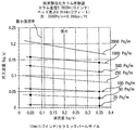
図4は、抵抗値が約0.01psig+5インチの流体深さに打ち勝つためのヘッドの1.52psigである5インチカラムの張水実験を示す。これらの損失および他の圧縮コストは、発電所ベースで1%未満しか費やさないものと予想され、そのようなものとして、僅少とみなし、実施例では計算しない。図4は、流路中のきわめて低い抵抗が結果としてきわめて低いエネルギー圧縮を生じさせて、装置のエコロジー効率が圧縮またはガスの取り扱いに消費される過剰なエネルギーによって損なわれないという効果をもたらした。 FIG. 4 shows a 5 inch column hydration experiment where the resistance is 1.52 psig of head to overcome a fluid depth of about 0.01 psig + 5 inches. These losses and other compression costs are expected to spend less than 1% on a power plant basis, as such, are considered insignificant and are not calculated in the examples. FIG. 4 has the effect that the very low resistance in the flow path results in very low energy compression, so that the ecological efficiency of the device is not compromised by the excess energy consumed for compression or gas handling.
本方法および装置の態様のエコロジー効率は、CO2を吸収するための可能な最小限の作業を実施することによって高められ、その効率を損なう一つの要因は、この工程を達成するために必要な圧縮、流体および空気のポンピングの量である。そのためには、二つの高効率吸収剤(N2中60%CO2である、入ってくる煙道ガスからCO2を99%除去することができる)が、高いCO2吸収率を達成する「短い段」で作動するように設計される。 Ecological efficiency of embodiments of the method and apparatus is enhanced by performing a least work possible to absorb CO 2, one factor that impairs the efficiency required to achieve this step The amount of compression, fluid and air pumping. To that end, two high-efficiency absorbents (60% CO 2 in N 2 that can remove 99% CO 2 from incoming flue gas) achieve high CO 2 absorption rates. Designed to operate in “short stages”.
本発明の好ましい態様は、広い面積の液気移行面(バブルカラム、充填もしくは中空または固定もしくは移動流体容器におけるその等価物)を使用して、短い高さの流体吸収剤で高い吸収率を達成し、それにより、流体どうしを接触させるために必要な抵抗を減らし、したがって、この「短段設計」は、広く短い「貯留部」または配管、溝、容器等におけるその等価物を用いて多量のCO2を効率的に吸収することを要する。 A preferred embodiment of the present invention uses a large area liquid-gas transfer surface (bubble column, packed or hollow or its equivalent in a fixed or moving fluid container) to achieve high absorption with a short height fluid absorbent. And thereby reducing the resistance required to bring fluids into contact, so this “short design” uses a large and short “reservoir” or its equivalent in pipes, grooves, containers, etc. It needs to absorb CO 2 efficiently.
本開示の脱炭酸塩化反応は一般に、主流産業およびすべてのその参考文献によって物質移動制限的であると考えられている。実際には、広い面積の気液接触吸収を有する充填または非充填カラムを流体中気泡上昇法で使用すると、反応は、物質移動制限をほとんど受けないと思われる。言い方を変えるならば、液気接触のためのバブルカラム設計の本方法の使用は、物質移動制限を楽に解消すると思われる。ゼロ充填でわずか30cmの気/液接触距離のスパージャに通すバブリングが、98%+の瞬間的なCO2吸収率を生じさせることが実証され(実施例3で論じるように図2Bおよび2Cを参照)、工業的に有意な15〜25分のタイムフレームでは、流体は平均80%+もの吸収能力を保持する。これは、深刻な物質移動制限を受けているとは言い難く、実験は、消失までの簡単な充填負荷運転の場合でさえ、この化学吸着の容易な物質移動を実証する。 The decarboxylation reaction of the present disclosure is generally considered mass transfer limited by the mainstream industry and all its references. In practice, when packed or unpacked columns with large area gas-liquid contact absorption are used in the bubble-in-fluid method, the reaction appears to be almost free from mass transfer restrictions. In other words, the use of this method of bubble column design for liquid-gas contact seems to ease the mass transfer restrictions easily. Bubbling through a sparger with zero fill and a gas / liquid contact distance of only 30 cm has been demonstrated to produce an instantaneous CO 2 absorption rate of 98% + (see FIGS. 2B and 2C as discussed in Example 3) ) In an industrially significant 15-25 minute time frame, the fluid retains an average of 80% + absorption capacity. This is unlikely to be subject to severe mass transfer restrictions, and experiments demonstrate this easy chemisorption mass transfer even in the case of a simple charge-load operation until disappearance.
高吸収CO2/NaOH吸収リアクタの設計の三つの例が実施例1〜3で詳細に説明される。実施例1〜3から導かれる結論は、短いNaOH段の高い吸収率が、製造可能な寸法の容器の中で低い抵抗で入ってくるCO2の高い割合を工業的に除去することができると証明され、実証されるということである。 Three examples of high absorption CO 2 / NaOH absorption reactor designs are described in detail in Examples 1-3. Conclusions drawn from Examples 1-3, high absorption of short NaOH stage, when a high percentage of incoming CO 2 at low resistance in a container manufacturable size can be industrially removed It is proven and proven.
要するに、本発明の特定の態様は、方法および装置の脱炭酸塩化部分に関して、以下の属性を一つまたは複数を含む:
(1) 反応の炭酸塩化段階におけるCO2の高い吸収率を達成するための短い段の使用;
(2) 炭酸水素塩化工程における、CO2含有工程ガス(またはCO2濃度が吸収性流体からのCO2再生の分圧よりも大きい他のCO2含有ガス)との連続的な接触による炭酸塩化流体の分離および処理;
(3) 純粋な炭酸水素塩、純粋な炭酸塩およびそれらの間のすべての様々な混合物を製造するための、状態変量および濃度のプロセス制御によって使用することができる工程シーケンスの所有;ならびに
(4) 本発明の態様は、1:1ナトリウム/炭素吸収比と同じくらい効率的であることができる;これは、反応体を製造する際に使用されるkw-hrあたり吸収されるCO2(エコロジー効率(∂CO2/∂E)の変形)を最適化する。
In summary, certain aspects of the present invention include one or more of the following attributes with respect to the decarboxylation portion of the method and apparatus:
(1) Use of a short stage to achieve high CO 2 absorption in the carbonation stage of the reaction;
(2) Carbonation by continuous contact with a CO 2 -containing process gas (or other CO 2 -containing gas whose CO 2 concentration is higher than the partial pressure of CO 2 regeneration from the absorbent fluid) in the bicarbonate process Fluid separation and processing;
(3) ownership of a process sequence that can be used by process control of state variables and concentrations to produce pure bicarbonate, pure carbonate and all the various mixtures between them; and
(4) Embodiments of the invention can be as efficient as a 1: 1 sodium / carbon absorption ratio; this is the CO 2 absorbed per kw-hr used in making the reactants. Optimize the (ecology efficiency (variation of ∂CO 2 / ∂E)).
IV. 生成物の分離
上記のように、特定の態様では、本開示の装置および方法は、液体溶液から炭酸塩および炭酸水素塩生成物を分離する分離工程を使用する。液体溶液生成物の分離はそれに伴う工程を要する。水酸化ナトリウム(NaOHまたは苛性ソーダ)で平衡した液体中の炭酸水素ナトリウム(NaHCO3または重炭酸ナトリウム)および炭酸ナトリウム(Na2CO3またはソーダ灰)の形成は、広い範囲の温度および圧力で起こり、異なるCO2分圧を与えられると異なる平衡の終点を提供する。基本的な濃度、温度、圧力、リアクタサイズ、流体深さおよび炭酸塩化度を操作することにより、炭酸塩および炭酸水素塩の沈殿物を生じさせることができる。または、いくつかの好ましい態様では、炭酸塩/炭酸水素塩生成物は、入ってくる煙道ガスとの熱交換により、水から分離することができる。さらには、炭酸ナトリウムと炭酸水素ナトリウムとの間の溶解度生成物定数差により、特定の非直感的処理点に達することができる;たとえば、特定の苛性アルカリ溶液中の炭酸ナトリウムの平衡の特異性の一つは、熱の付加が固体の沈殿を促進するということである;また、特定の条件で、炭酸塩は、水溶液から高い(93%+)純度で自己沈殿するということが実証された。
IV. Product Separation As noted above, in certain embodiments, the devices and methods of the present disclosure use a separation step that separates carbonate and bicarbonate products from a liquid solution. Separation of the liquid solution product requires associated steps. The formation of sodium bicarbonate (NaHCO 3 or sodium bicarbonate) and sodium carbonate (Na 2 CO 3 or soda ash) in a liquid equilibrated with sodium hydroxide (NaOH or caustic soda) occurs over a wide range of temperatures and pressures, Provide different CO 2 partial pressures to provide different equilibrium endpoints. Manipulating basic concentrations, temperatures, pressures, reactor sizes, fluid depths and carbonation degrees can produce carbonate and bicarbonate precipitates. Alternatively, in some preferred embodiments, the carbonate / bicarbonate product can be separated from the water by heat exchange with the incoming flue gas. Furthermore, the solubility product constant difference between sodium carbonate and sodium bicarbonate can reach a specific non-intuitive treatment point; for example, the specificity of the equilibrium of sodium carbonate in a particular caustic solution One is that the addition of heat promotes solid precipitation; it was also demonstrated that, under certain conditions, carbonate self-precipitates from aqueous solution with high (93% +) purity.
または、特定の態様では、分離工程のための熱は、最初の電気分解で発生した水素から導出することもできるし、入ってくる煙道ガス流に含まれる廃熱の創作的な使用から導出することもできる。結晶化工程は、本来、結晶化による周知の精製工程によって結晶性鉱物を精製する。 Alternatively, in certain embodiments, the heat for the separation process can be derived from the hydrogen generated in the initial electrolysis or derived from the creative use of waste heat contained in the incoming flue gas stream. You can also In the crystallization step, the crystalline mineral is originally purified by a well-known purification step by crystallization.
出口の液流は、リアクタ設計に依存して、水、NaOH、NaHCO3、Na2CO3および他の溶解ガスを種々の平衡状態で含むことができる。溶解した極微量放出成分、たとえばH2SO4、HNO3およびHgをも見いだすことができる。一つの態様では、出る液流を分離/除去する、たとえば炭酸塩から水を除去/分離するためには(この語の意味において、「炭酸塩」は、潜在的に存在する水酸化物をも含む、炭酸塩と炭酸水素塩との混合物を意味する;任意のこのような混合物に適用される任意の分離技術は、熱エネルギーを加えて混合物から水を蒸発させることを含む場合が多い)、図6に示すリボイラ106を使用して水を沸騰させて水を蒸発させることができる。または、部分的な基本溶液(たとえば約1モルのNaOH)を保持し、続いて、その溶液を分離チャンバで加熱することにより、相対的に純粋なNa2CO3を保持タンク中に沈殿させることができ、残るNaOHが再循環してリアクタ200に戻る。他の態様では、その後、平衡濃度および/またはスラリーもしくは濃縮形態にある純粋な炭酸塩、純粋な炭酸水素塩およびそれら二つの混合物を定期的にトラック/タンク車に輸送することもできる。他の態様では、液流を蒸発タンク/フィールドに移動させて、そこで、水のような液体を蒸発によって留去してもよい。
The outlet liquid stream can contain water, NaOH, NaHCO 3 , Na 2 CO 3 and other dissolved gases in various equilibrium states, depending on the reactor design. Dissolved trace release components such as H 2 SO 4 , HNO 3 and Hg can also be found. In one embodiment, to separate / remove the outgoing stream, for example to remove / separate water from the carbonate (in the sense of this term, “carbonate” refers to any potentially present hydroxide. Including a mixture of carbonate and bicarbonate; any separation technique applied to any such mixture often involves applying thermal energy to evaporate water from the mixture). The
図6を参照すると、図示するリアクタ設計は、電気分解された水素中に貯蔵されたエネルギーを燃焼燃料、ボイラガスとして、またはH2/O2燃料セルのいずれかにおいて回収することができる。リアクタ200は、NaOHおよびNaHCO3を約50:50の割合で製造することができる定常状態作動を生じさせるために使用することができる。最初の電気分解で生成した水素ガスを使用して熱を提供し、NaHCO3を分離チャンバ108中で沈殿させて残りのNaOHをリアクタ200に還流させることもできる。分離チャンバ108からのスラリーは、分離チャンバ108に結合していることができる水処理チャンバ110に提供することができる。または、スラリーは、貯蔵しておき、後で必要に応じて水処理チャンバ110に提供することもできる。
Referring to FIG. 6, the illustrated reactor design can recover energy stored in electrolyzed hydrogen, either as combustion fuel, boiler gas, or in an H 2 / O 2 fuel cell. The
図7は、本発明の態様によるもう一つのリアクタ設計を示す。特に、図7は、水素副生成物を製造するために使用される余剰エネルギーの再捕捉を示す。タンデムオンサイト高効率燃料セルの使用は、電気分解電流を捕捉し、部分的に供給するために使用することができる直流回収を可能にすることができる。混合チャンバ300が、NaOH、NaHCO3およびNOx、SOxおよびHgの割合をはじめとし、非限定的に混和物を分離チャンバ308に提供する。分離チャンバ308は、混和物に熱を提供することによって混和物を固相および/または液相に分離することができる。分離チャンバ308の乾燥チャンバ(図示せず)が工程中に熱を加えることによって固相および/または液相から液体を除去することができる。得られる希釈形態のNaOHがボイラ306に提供され、このボイラが希釈NaOHを濃縮形態に沸騰させ、還流ループを介して濃縮物を混合チャンバ300に提供する。ボイラ306からの水は、電気分解チャンバ302、特にブラインミキサ302Aに提供することができる。分離チャンバ308から得られるNa2CO3/NaHCO3(スラリー)は、市販用に供することができる。一つの態様では、炭酸塩スラリーは、直接的または間接的(たとえばNaHCO3を後で硬水処理のような工程で使用するために貯蔵する)に水処理プラント310に提供することができる。または、NaHCO3は、さらに精製し、乾燥させ、出荷し、他の工業用に提供することもできる。
FIG. 7 illustrates another reactor design according to an embodiment of the present invention. In particular, FIG. 7 illustrates the recapture of surplus energy used to produce hydrogen by-products. The use of a tandem on-site high efficiency fuel cell can allow direct current recovery that can be used to capture and partially supply electrolysis current. Mixing
気体生成物の放出は、NaOHまたは同種の成分を安全に放出することができるかどうか、すなわち、発電所からの「塩基性雨」の放出が「酸性雨」の放出と同等に避けられるかどうかの懸念を含む。しかし、水酸化ナトリウムは通常、発電所生産におけるスクラビング要素として使用され、EPAによって使用を認められている。発電所における水酸化ナトリウムの取り扱いならびに塩基性放出物を回避する手法は当該技術で周知である。たとえば、簡単で廉価な凝縮器/還流ユニットが排気物中のNaOHの任意の有意な放出を防ぐことができる。 Whether the release of gaseous products can safely release NaOH or similar components, i.e. whether the release of "basic rain" from power plants can be avoided as much as the release of "acid rain" Including concerns. However, sodium hydroxide is usually used as a scrubbing element in power plant production and has been approved for use by the EPA. Handling sodium hydroxide at power plants and techniques for avoiding basic emissions are well known in the art. For example, a simple and inexpensive condenser / reflux unit can prevent any significant release of NaOH in the exhaust.
本発明の特定の態様の炭酸塩分離沈殿法では、炭酸塩平衡が二酸化炭素を立体的に束縛し、接触によってガスを吸収し、実質的に瞬時に炭酸イオンへと転換する。反応連鎖は、ひとたび二酸化炭素が塩基によって吸収されると、その後のイオン反応が急速なペースで起こるように物質移動制限されるかもしれない。 In the carbonate separation and precipitation method of a particular embodiment of the present invention, the carbonate equilibrium sterically constrains carbon dioxide, absorbs the gas upon contact, and converts it to carbonate ions substantially instantaneously. The reaction chain may be mass transfer restricted so that subsequent ionic reactions occur at a rapid pace once carbon dioxide is absorbed by the base.
炭酸ナトリウム平衡は、温度は上昇するが、Na2CO3が自然に沈殿し、集まり、それによってスラリーとして回収しやすくし、いくらかの分画NaOHがスラリー中に抜き取られるという特性を有する。一つの態様では、塩素サイクルで製造された湿塩素のいくらかを用いるこのスラリーの表面にじみ処理を使用して、地下の「トロナ」または埋蔵物を採掘することによって生産された炭酸ナトリウムを近似するまたはそれ未満のレベルでNaOHをNaHCO3中の極微量NaClに還元することもできる。そのようなものとして、炭酸ナトリウム/苛性アルカリ平衡は、気体から液体、固体への完全な輸送を炭素に提供する。他の態様では、灰、水酸化ナトリウムおよび他の種々の炭酸塩ならびに不純物のスラリーを収集するための収集媒体として炭酸塩ループを使用し、スラリーを陸路でトラック輸送することが有益であるかもしれない。 The sodium carbonate equilibrium has the property that although the temperature increases, Na 2 CO 3 precipitates spontaneously and collects, thereby facilitating recovery as a slurry and some fractional NaOH is withdrawn into the slurry. In one embodiment, the surface treatment of this slurry with some of the wet chlorine produced in the chlorine cycle is used to approximate the sodium carbonate produced by mining underground “trona” or reserves, or Lower levels of NaOH can also be reduced to trace amounts of NaCl in NaHCO 3 . As such, the sodium carbonate / caustic equilibrium provides carbon with complete transport from gas to liquid to solid. In other embodiments, it may be beneficial to use a carbonate loop as a collection medium to collect a slurry of ash, sodium hydroxide and other various carbonates and impurities, and truck the slurry overland. Absent.
V. 吸収性流体の低エネルギー製造のためのブライン電気分解
上記のように、特定の態様では、本開示の装置および方法は、脱炭酸塩化工程における吸収性流体として使用される水酸化ナトリウムの製造のためにブライン電気分解を使用する。ブライン電気分解は、濃縮水酸化ナトリウム(苛性ソーダ)および塩素ガスの製造で主に使用される電気化学的工程であり、典型的に、関連の文献を通じて以下の式によって記載されている。
2NaCl+2H2O+e-→2NaOH+H2(g)+Cl2(g)
V. Brine electrolysis for low energy production of absorbent fluids As noted above, in certain embodiments, the apparatus and method of the present disclosure provides for the production of sodium hydroxide used as an absorbent fluid in a decarboxylation process. Use brine electrolysis. Brine electrolysis is an electrochemical process primarily used in the production of concentrated sodium hydroxide (caustic soda) and chlorine gas and is typically described by the following formula throughout the relevant literature.
2NaCl + 2H 2 O + e- → 2NaOH + H 2 (g) + Cl 2 (g)
ブライン電気分解は、三つの一般的なタイプの標準電気分解セル、すなわち隔膜、水銀および膜セルよって達成することができる。これらのタイプのセルそれぞれが同じ投入反応体から同じ産出生成物を製造する。これらは、主に反応体および生成物が互いから分離される方法において互いに異なる。 Brine electrolysis can be accomplished with three general types of standard electrolysis cells: diaphragm, mercury and membrane cells. Each of these types of cells produces the same output product from the same input reactant. These differ from each other primarily in the manner in which the reactants and products are separated from each other.
一つの態様では、膜セルは、いくつかの要因のため使用することができる。第一に、水銀に関する環境的懸念が水銀セルの需要を減らした。第二に、隔膜セルは、有意な濃度の塩および塩化物イオンを含有する相対的に弱い苛性アルカリ生成物を製造することができ、その苛性アルカリから有意な塩含量を除去するために相当な後続の再処理/分離を要する。第三に、フッ素化ポリマー技術における改良が膜セル技術の寿命および電気的効率を延ばし、5年を超える寿命が工業市場で通常に保証されている。さらには、苛性アルカリ1トンあたりの電力効率は、好ましい具現化では、隔膜セルおよび水銀セルの両方の効率を超える。 In one embodiment, the membrane cell can be used for several factors. First, environmental concerns about mercury have reduced the demand for mercury cells. Secondly, the diaphragm cell can produce a relatively weak caustic product containing significant concentrations of salt and chloride ions, which is significant to remove significant salt content from the caustic. Subsequent reprocessing / separation is required. Third, improvements in fluorinated polymer technology extend the lifetime and electrical efficiency of membrane cell technology, and lifetimes of more than 5 years are usually guaranteed in the industrial market. Furthermore, the power efficiency per tonne of caustic exceeds the efficiency of both the diaphragm cell and the mercury cell in the preferred implementation.
膜セル処理ユニットは、以下の一般化された投入および産出によって典型的に示されるが、これに限定されない。
陽極:26% NaCl投入+2275kwh/トンCl2→Cl2(g)+24% NaOH
陰極:H20投入+e-→30〜33% NaOH+H2(g)
A membrane cell processing unit is typically illustrated by the following generalized inputs and outputs, but is not limited thereto.
Anode: 26% NaCl input + 2275kwh / ton Cl 2 → Cl 2 (g) + 24% NaOH
Cathode:
所要電力(たとえば2275kwh/塩素1トン)は、個々の電気分解セル設計に依存することができることが注目される。そのようなものとして、所要電力は異なる。 It is noted that the power requirements (eg 2275 kWh / ton of chlorine) can depend on the individual electrolysis cell design. As such, the power requirements are different.
多くの好ましい態様は、膜セルをこの機能に使用することができる。膜セルには他のブライン電気分解工程を上回る利点がいくつかある。まず、膜セルは、任意の環境的に敏感な放出物(たとえば水銀)を含有もせずまたは製造もせず、隔膜セルおよび水銀セルと比較した場合、電気的に効率的である。また、連続的な「塩ループ」処理ユニットとしての使用に好適であるよう、濃縮/希釈/補充NaClループを使用する。次に、膜セルで製造されたNaOHは、さらなる蒸発/濃縮なしでも、脱炭酸塩化工程における使用にとって自然に適切な濃度レベル(たとえばNaOH30〜33重量%)であることができる。さらには、膜セルによって製造された水素は、おおむね「電子用」の「クリーンさ」であり、NaClまたは他の汚染を比較的含まない。そのようなものとして、水素を圧縮し、電子用H2ガスとしてタンクから出し、現場での発電、たとえば低級石炭との燃焼配合剤または燃焼技術利得のために使用することができる。または、水素は、脱炭酸塩化ののち起こることができる分離工程のためのボイラ燃料として使用することもできる。膜セル技術はまた、小さな増分ユニットの追加によって実験室生産からプラント規模生産まで容易にスケーリングすることができる。さらには、膜工程によって製造された塩素ガスは、他の標準電気分解工程によって製造されたものよりも「湿潤」していない。そのようなものとして、水処理用塩素の製造には一段階圧縮サイクルが十分であるかもしれない。 Many preferred embodiments can use membrane cells for this function. Membrane cells have several advantages over other brine electrolysis processes. First, membrane cells do not contain or produce any environmentally sensitive emissions (eg, mercury) and are electrically efficient when compared to diaphragm cells and mercury cells. Also, a concentration / dilution / replenishment NaCl loop is used to be suitable for use as a continuous “salt loop” processing unit. The NaOH produced in the membrane cell can then be at a concentration level that is naturally appropriate for use in a decarbonation process (eg, NaOH 30-33 wt%) without further evaporation / concentration. Furthermore, the hydrogen produced by the membrane cell is generally “clean” for “electronics” and relatively free of NaCl or other contamination. As such, hydrogen can be compressed and discharged from the tank as electronic H 2 gas and used for on-site power generation, for example, combustion blends with lower coal or combustion technology gains. Alternatively, hydrogen can be used as boiler fuel for a separation process that can occur after decarboxylation. Membrane cell technology can also be easily scaled from laboratory production to plant scale production with the addition of small incremental units. Furthermore, the chlorine gas produced by the membrane process is less “wet” than those produced by other standard electrolysis processes. As such, a one-stage compression cycle may be sufficient for the production of water treatment chlorine.
上記は、市販用塩素ガスおよび苛性ソーダを製造する目的に向けて通常に達成されるような、公表され、実施されている技術水準を表す。しかし、本発明の特定の態様のねらいはいくつかの点で異なり、それが、本発明の特定の態様の異なる目的を達成するために使用される種々の化学的技術につながる。 The above represents the published and practiced state of the art as normally achieved for the purpose of producing commercial chlorine gas and caustic soda. However, the aims of certain aspects of the invention differ in several ways, leading to various chemical techniques used to achieve the different objectives of certain aspects of the invention.
A. 低電圧電気分解技術の使用
本発明のいくつかの態様では、ブライン電気分解は、低電圧電気分解(LVE)技術を取り入れて、それにより、工程の熱力学的効率を改善する。本発明の特定の態様は、最終生成物として苛性ソーダを排他的に製造するわけではなく、代わりに、NaOHを主に中間体吸収剤として使用して、煙道ガスを環境に出す前に煙道ガスからCO2を吸収する。塩素アルカリ産業は一般に、苛性ソーダを製造工場からその使用地点まで出荷することを伴うため、苛性ソーダ中の多量の水を輸送することは不経済であり、したがって、苛性アルカリは一般に、液体として出荷されるため、蒸発による水のエネルギー集中的除去により、約55重量%まで濃縮され、場合によっては、一般的なペレット化形態の無水固体まで濃縮される。この濃縮は、非常に一般的には、電気分解セルを5Vを超える電圧(特有の用語では「有意な過電圧」)で作動させることによって達成され、それが、上述の30〜35%NaOHを達成し、その後、蒸発サイクルを実施して55%を達成する(または生成物を無水パレット化状態まで完全に乾燥させる等)。
A. Use of Low Voltage Electrolysis Technology In some embodiments of the present invention, brine electrolysis incorporates low voltage electrolysis (LVE) technology, thereby improving the thermodynamic efficiency of the process. Certain embodiments of the present invention do not exclusively produce caustic soda as the final product, but instead use NaOH primarily as an intermediate absorbent, before the flue gas is vented to the environment. Absorbs CO 2 from the gas. Because the chlor-alkali industry generally involves shipping caustic soda from the manufacturing plant to its point of use, it is uneconomical to transport large amounts of water in caustic soda, and caustic is generally shipped as a liquid. Therefore, it is concentrated to about 55 wt% by energy intensive removal of water by evaporation, and in some cases, concentrated to anhydrous solids in the general pelletized form. This concentration is very generally achieved by operating the electrolysis cell at a voltage above 5V (in the specific term "significant overvoltage"), which achieves the 30-35% NaOH mentioned above. Then an evaporation cycle is performed to achieve 55% (or the product is completely dried to an anhydrous palletized state, etc.).
本発明の大部分の態様は、NaOHを生成物としては輸送せず、NaOHは、塩素アルカリプラント運転で使用される5V+標準よりも有意に低い電圧で、使用可能な濃度で(水性吸収性流体として)製造可能である。消費電力は簡単な直流式に正確に準ずるため、本発明の熱力学的効率に対するLVE使用の影響が過大評価されることはない。
P=V(電圧)×I(電流)×(電流効率)
Most aspects of the invention do not transport NaOH as a product, which is at a significantly lower voltage than the 5V + standard used in chlor-alkali plant operation, at usable concentrations (aqueous absorbent fluids). As possible). Since the power consumption is exactly according to a simple DC type, the influence of the use of LVE on the thermodynamic efficiency of the present invention is not overestimated.
P = V (voltage) x I (current) x (current efficiency)
電流は電気化学的工程(分子ごとに1対の電子等)によって固定されるため、電力は、電気分解するのに必要な電圧によってほぼ完全に規制される(さらなる強力な要因は電流効率であり、これもまた、印加電圧の関数である)。本発明の態様は、標準的電気化学的膜セルに対する工程および幾何学的改変による2.1Vの低さの作動条件の変更により、標準的電気分解セルで容易に実証される電圧でLVEを使用するため、本発明の態様は、形成されるNaOHの量に対し、従来の高電圧塩素アルカリ電気分解よりも少ない電力(kw-hr)しか消費しない。これらの理由のため、本発明の好ましい態様は、微小ギャップ作動、高めの圧力、大面積膜、陽極液および陰極液の濃度変化ならびにプロトン化イオン比をはじめとし、非限定的な、低電圧作動を達成するために利用可能なすべての技術を使用するように設計されている電気分解ユニットを含む。LVEのさらなる態様は実施例4で詳細に説明される。 Since the current is fixed by an electrochemical process (such as a pair of electrons per molecule), the power is almost completely regulated by the voltage required to electrolyze (an additional powerful factor is current efficiency). This is also a function of the applied voltage). Embodiments of the present invention use LVE at a voltage that is easily demonstrated in standard electrolysis cells by changing the operating conditions as low as 2.1V due to process and geometric modifications to standard electrochemical membrane cells Thus, embodiments of the present invention consume less power (kw-hr) than conventional high voltage chlor-alkali electrolysis for the amount of NaOH formed. For these reasons, preferred embodiments of the present invention include, but are not limited to, low voltage operation, including microgap operation, higher pressure, large area membranes, anolyte and catholyte concentration changes and protonated ion ratios. Including an electrolysis unit that is designed to use all available technologies to achieve. Further aspects of LVE are described in detail in Example 4.
B. 「無差別点」水素使用
典型的な塩素アルカリ処理は、蒸発のためのボイラ燃料として現場で燃やされるか(上記を参照)、または多くの場合、空気電極;たとえば酸素含有気を陰極に吹き込んで速やかな還元反応
H2(g)+1/2O2(g)→H2O(1/g)
を起こさせる装置の使用によって全体的に抑制されるかいずれかの水素ガスを製造し、それが、エネルギーの電気化学的合計を変化させ、水素を製造しない費用で苛性アルカリおよび塩素を製造するために必要な電圧(場合によっては、様々な工業文献では2.8Vの低さ)を下げる。本発明の好ましい態様の利点は、蒸発ボイラ燃料として水素が必要ないということである。
B. Use of “promiscuous” hydrogen Typical chlor-alkali treatments are either burned in-situ as boiler fuel for evaporation (see above) or often air electrodes; for example oxygen-containing gas to the cathode Rapid reduction reaction by blowing
H 2 (g) + 1 / 2O 2 (g) → H 2 O (1 / g)
To produce either hydrogen gas, which is totally suppressed by the use of a device that causes hydrogen, which changes the electrochemical sum of energy and produces caustic and chlorine at the expense of not producing hydrogen To reduce the voltage required (sometimes as low as 2.8V in various industry literature). An advantage of a preferred embodiment of the present invention is that hydrogen is not required as the evaporative boiler fuel.
本発明のいくつかの態様は、水素製造を抑制する(かつ、その水素からエネルギーを回収する能力をゼロにする)「空気電極」法を含むことができるが、多くの好ましい態様は、水素の製造をエネルギー帰還のためにまたは他の工程の原料薬品のいずれかとして利用する。 While some aspects of the present invention can include an “air electrode” process that inhibits hydrogen production (and zeroes its ability to recover energy from the hydrogen), many preferred aspects include hydrogen Manufacturing is utilized either for energy return or as a raw chemical for other processes.
したがって、本発明の特定の態様を使用するプラントは、そのようにして製造された水素の使用に関して「無差別点」を有する;すなわち、プラントは、そのエネルギー帰還(たとえば、例示的な場合、そのエネルギー量の60%)のために水素を製造し、そのエネルギーの量は特定の経済的価値を有し、エネルギー帰還のために水素を使用する代わりに、その水素を、エネルギー単独でのその経済的価値を越えるかもしくは等しい量に関して取引または販売することができる。このようにして、このタイプのプラントは、ある種の「水素の井戸」に相当する。水素は、その電気的価値のために製造され、消費され、他の目的に水素を所望する者は、その電気的価値またはその経済的等価物を取引して工程の経済性を維持するだけでよい。この態様は、将来的な「水素経済」計画にとって利益の暗示を有する。生得のエネルギー量よりも低い価格無差別コスト点で利用可能な水素の安易な供給源を有することは、この技術の有用かつ有利な特徴を証明するかもしれない。 Thus, a plant that uses a particular aspect of the present invention has a “promiscuous point” with respect to the use of hydrogen so produced; that is, the plant has its energy feedback (eg, in the illustrative case, its 60% of the amount of energy), the amount of energy has a certain economic value, instead of using hydrogen for energy return, instead of using hydrogen for energy return, Can be traded or sold in quantities that exceed or equal the target value. This type of plant thus represents a kind of “hydrogen well”. Hydrogen is manufactured and consumed for its electrical value, and those who desire hydrogen for other purposes can simply trade its electrical value or its economic equivalent to maintain the economics of the process. Good. This aspect has implications for future “hydrogen economy” plans. Having an easy source of hydrogen available at a price indiscriminate cost lower than the amount of natural energy may prove a useful and advantageous feature of this technology.
C. プロトン化ブライン最適化技術の使用
本発明の特定の態様は、水素の製造を抑制するのではなく、以下のプロトン化ブライン最適化手段によってそれを意図的に最適化する。一般的な塩素アルカリ産業は、場合により、塩酸の形態のHClを陽極液チャンバと呼ばれるブライン(NaCl)セルに添加することを用いてきた。このブラインの「プロトン化」は、本発明の特定の態様の反応体/吸収剤を製造するのに必要な電力を減らすという点で、指定量の苛性アルカリを製造するために必要な電圧を下げる効果を有する。塩素アルカリプラントの通常の作業体系では、この電圧低下効果の原因は、膜選択性等に対して研究されてきた工程である「膜を透過して帰還するNaOHの中和」に帰され、十分に理解されている。概して、この「中和」は、塩水のみを製造するものとみなされ[NaOH(帰還)+HCl(陽極液)→NaCl+H2O]、生成物の化学量論比を変化させるとは示されていない。しかし、当技術分野で十分に理解または活用されていない一つの点は、HClの添加が実際に式の化学量論比を以下のように根本的に変化させるということである。
NaCl+aHCl+H2O→NaOH+(1/2+a/2)H2+(1/2+a/2)Cl2
C. Use of Protonated Brine Optimization Techniques Certain embodiments of the present invention do not suppress the production of hydrogen, but intentionally optimize it by the following protonated brine optimization means. The general chlor-alkali industry has sometimes used the addition of HCl in the form of hydrochloric acid to a brine (NaCl) cell called an anolyte chamber. This “protonation” of brine lowers the voltage required to produce a specified amount of caustic in that it reduces the power required to produce the reactant / absorbent of a particular embodiment of the invention. Has an effect. In the normal work system of a chlor-alkali plant, the cause of this voltage drop effect is attributed to “neutralization of NaOH returning through the membrane”, a process that has been studied for membrane selectivity, etc. Is understood. In general, this “neutralization” is considered to produce only salt water [NaOH (feedback) + HCl (anolyte) → NaCl + H 2 O] and is shown to change the stoichiometric ratio of the product. It has not been. However, one point that is not well understood or utilized in the art is that the addition of HCl actually changes the stoichiometric ratio of the formula as follows:
NaCl + aHCl + H 2 O → NaOH + (1/2 + a / 2) H 2 + (1/2 + a / 2) Cl 2
本発明の態様は水素からのエネルギー回収(より多くの水素が製造される場合に増大し、製造される吸収性NaOH 1モルあたりより多くの塩素ガスが製造される場合により経済的になる)に依存するため、製造される水素および塩素のこのさらなる量が本発明にとって特に興味深い。全体的な電圧(ひいては、電力およびコスト)が減る一方でエネルギー回収のための水素および販売用塩素のさらなる賞与が得られるということが、本発明の特定の態様が、反応体を製造するための最低エネルギーおよび生成物から回収する最高エネルギーの値「a」を最適化することにつながる。最適値は一般に、NaCl(水性)溶液中0.5〜1.0M HClの範囲である。しかし、最適化は、各セルの設計、形状大きさ、濃度、温度および圧力領域ごとに特異的である。しかし、各電気化学セルごとに、最低エネルギー作動を達成する最適なプロトン化率「a」がある。実際には、きわめて高い「a」値(たとえば90℃で>0.15M)は、おそらくは、大部分の市販の膜を短時間で膨れさせるであろう。当然、HClが本発明におけるブラインのプロトン化に好ましい酸であるが、当業者に公知であるような多くの他の酸を使用してブラインをプロトン化することもできる。 Embodiments of the present invention provide for energy recovery from hydrogen (increased when more hydrogen is produced and becomes more economical when more chlorine gas is produced per mole of absorbed NaOH produced). This additional amount of hydrogen and chlorine produced is of particular interest for the present invention because it depends. It is a particular aspect of the present invention for producing reactants that the overall voltage (and hence power and cost) is reduced, while further bonuses of hydrogen and chlorine for sale are obtained. This leads to optimizing the lowest energy and the highest energy value “a” recovered from the product. The optimum value is generally in the range of 0.5 to 1.0 M HCl in NaCl (aqueous) solution. However, the optimization is specific for each cell design, shape size, concentration, temperature and pressure region. However, for each electrochemical cell there is an optimal protonation rate “a” that achieves the lowest energy operation. In practice, very high “a” values (eg,> 0.15 M at 90 ° C.) will probably cause most commercial membranes to swell in a short time. Of course, HCl is the preferred acid for the protonation of brine in the present invention, but many other acids as known to those skilled in the art can be used to protonate the brine.
D. プロトン化に使用されるHClの自己製造
本発明の特定の態様は、投入されたHClを使用し、H2およびCl2ガスを製造する両方のため、ブラインのプロトン化は、自己往復性にすることができる;すなわち、H2およびCl2生成物ガスを燃焼させて(効率的な燃料セルまたは通常のバーナで)HClガスを製造したのち、そのHClガスを陽極液にリサイクルしてブラインのプロトン化を実施することができる。H2/Cl2燃焼から回収されるエネルギーは、H2/O2燃焼から回収されるエネルギーよりも大きい。これが本発明の熱力学的効率を増す。
D. Self-production of HCl used for protonation Certain embodiments of the invention use charged HCl to produce both H 2 and Cl 2 gas, so that protonation of brine is self-reciprocating. Ie, by burning the H 2 and Cl 2 product gases (with an efficient fuel cell or conventional burner) to produce HCl gas, the HCl gas is recycled to the anolyte to brine. The protonation of can be carried out. The energy recovered from H 2 / Cl 2 combustion is greater than the energy recovered from H 2 / O 2 combustion. This increases the thermodynamic efficiency of the present invention.
本発明のいくつかの好ましい態様は、吸収/転換/再生経路を「フロントエンド濃縮/吸収工程」として使用し、この工程を使用して、以下の手段または類似の手段によって地質、海洋または陸上隔離技術(たとえばCO2を炭素バンクに注入する技術)で使用するためにCO2を吸収し、濃縮する:
(1) すべての水素を燃焼させてHClガスを製造する。
(2) すべてのHClガスを、そのようにして製造された炭酸水素ナトリウムと反応させる。
(3) 関連する中和反応を経て、ほぼ100%純粋なCO2が放出され、塩水が再生されると、その塩水をさらなる吸収サイクルのためにリサイクルすることができる。
(4) この工程により、本発明は、CO2を吸収、転換および放出するために使用され、その正味の効果として、ガスが煙道流から除去され、その後に処理するためのさらなる隔離技術のために濃縮される。
Some preferred embodiments of the present invention use the absorption / conversion / regeneration pathway as a “front-end enrichment / absorption step”, which is used to geological, marine or terrestrial sequestration by the following or similar means: Absorb and concentrate CO 2 for use in technologies (eg, technologies that inject CO 2 into the carbon bank):
(1) Combustion of all hydrogen to produce HCl gas.
(2) React all HCl gas with the sodium bicarbonate so produced.
(3) When almost 100% pure CO 2 is released through the associated neutralization reaction and the brine is regenerated, the brine can be recycled for further absorption cycles.
(4) By this process, the present invention can be used to absorb, convert and release CO 2 with the net effect of further sequestration technology for gas removal from the flue stream and subsequent processing. To be concentrated.
E. 炭酸塩および炭酸水素塩の陰極分解流体への逆混入
塩素/水素セルの塩素アルカリ産業的使用とは違って、本発明のいくつかの態様はまた、炭酸塩および炭酸水素塩混合物を電気化学セルの陰極液(苛性アルカリ)側にリサイクルする。このような技術は広く異なるが、工程全体の各運転点は、一部の濃度および条件ではセル電圧、ひいてはセル電力を下げることができるため、炭酸水素塩/炭酸塩混合物の陰極液への最適なリサイクルを有する。
E. Back-mixing of carbonates and bicarbonates into the catholyzed fluid Unlike the chlor-alkali industrial use of chlorine / hydrogen cells, some embodiments of the present invention also provide for the conversion of carbonates and bicarbonate mixtures into electricity. Recycle to the catholyte (caustic) side of the chemical cell. Although such techniques vary widely, each operating point of the overall process can reduce cell voltage, and thus cell power, at some concentrations and conditions, making it ideal for catholyte of bicarbonate / carbonate mixtures. Have a good recycling.
F. 流体の加熱のための廃熱回収の使用
本発明の特定の態様は、発電所または煙道ガスもしくは燃焼からの他の高温ガスの形態の多量のCO2放出の存在で使用されるため、標準的塩素アルカリ工程とは違い、熱交換の機会が十分にある。たとえば、入ってくる煙道ガスの典型的な温度(たとえば静電沈殿処理ののち)はゆうに300℃になるかもしれない。陽極流体および陰極流体を加温しながら(LVEの場合、一般に>90℃に保持すべきである)その煙道ガスを300℃未満の点まで冷却すると、本発明の特定の態様は、陽極液および陰極液ヒータに伴う電力損失なしに作動することができる。
F. Use of Waste Heat Recovery for Fluid Heating Certain embodiments of the present invention are used in the presence of large amounts of CO 2 emissions in the form of power plants or other hot gas from flue gas or combustion. Unlike standard chlor-alkali processes, there are ample opportunities for heat exchange. For example, the typical temperature of incoming flue gas (eg after electrostatic precipitation) may be as much as 300 ° C. When the flue gas is cooled to a point below 300 ° C. while warming the anodic and cathodic fluids (which should generally be kept at> 90 ° C. for LVE), certain embodiments of the present invention provide an anolyte And can operate without the power loss associated with catholyte heaters.
G. 工程設備を駆動するための廃熱回収の使用
一般に、発電所で利用可能な煙道ガスは100℃(スクラビング済み、一般的)、300℃(沈殿処理後)および900℃(沈殿進入)またはそのような他の数値の間の温度で出るため、入ってくる煙道ガスを電力回収サイクル、たとえばアンモニア−水サイクル(たとえば「Kalina」特許法)、蒸気サイクルまたは同じ熱力学的手段を達成するそのようなサイクルとの熱交換に通して冷却することにより、相当な廃熱処理を抽出することができる。本発明の特定の態様は直流電力に依存して本発明の試薬/吸収剤の製造を達成するため、工程は、他の使用のために直流電力を交流電力に転換することに伴う通常の変成器損失なしで達成される廃熱回収によって部分的または完全に直接駆動されることができる。さらには、廃熱作動式エンジンの使用により、発電工程を全く用いることなく有意な効率を達成することができる。条件によっては、これらの廃熱回収エネルギー量が本発明の態様を完全を駆動するということがわかるかもしれない。
G. Use of waste heat recovery to drive process equipment Generally, flue gases available at power plants are 100 ° C (scrubbed, typical), 300 ° C (after precipitation) and 900 ° C (precipitation ingress) Or to exit at a temperature between such other numbers, the incoming flue gas is subjected to a power recovery cycle, such as an ammonia-water cycle (eg "Kalina" patent law), steam cycle or the same thermodynamic means By cooling through such a heat exchange with the cycle, considerable waste heat treatment can be extracted. Since certain embodiments of the present invention rely on direct current power to achieve the manufacture of the reagent / absorbent of the present invention, the process involves the normal transformation associated with converting direct current power to alternating current power for other uses. It can be driven partly or completely directly by waste heat recovery achieved without unit losses. Furthermore, the use of a waste heat operated engine can achieve significant efficiencies without using any power generation process. Depending on the conditions, it may be seen that these amounts of waste heat recovery energy drive the aspects of the present invention completely.
VI. 脱炭工程および電気分解工程からの副生成物の生成および使用
上記のように、本開示の装置および方法の特定の態様は、塩素ガス、炭酸水素ナトリウムおよび水素ガスをはじめとする、脱炭工程および電気分解工程からの多数の有用な副生成物を製造する。いくつかの態様では、本発明の態様によって製造される水素ガスは水素ガス再捕捉ループに組み込まれる。一つの態様では、本発明は、脱炭工程のために塩素イオン移動を減らすため、現在のフッ素化ポリマー膜技術を含むことができる。したがって、工程は、塩化物イオンを分離するための多量のエネルギーおよび経費なしで機能することができる;脱炭酸塩化および分離ループは比較的塩化物を含まない。そのようなものとして、本発明の脱炭酸塩化リアクタの態様は、一般的な塩、水および二酸化炭素排出物を電気と組み合わせて使用して、塩素ガス、炭酸水素ナトリウムおよび以下のような水素燃焼を介する電力回収を形成することができる。
2NaCl+H2O+2CO2+e-→2NaHCO3+Cl2+[1/2H2+原子O2→e-]
VI. Generation and Use of By-Products from the Decarburization and Electrolysis Process As noted above, certain aspects of the disclosed apparatus and method include degassing, including chlorine gas, sodium bicarbonate and hydrogen gas. A number of useful by-products from the charcoal and electrolysis processes are produced. In some embodiments, the hydrogen gas produced according to embodiments of the present invention is incorporated into a hydrogen gas recapture loop. In one embodiment, the present invention can include current fluorinated polymer membrane technology to reduce chloride ion migration for the decarburization process. Thus, the process can function without significant amounts of energy and expense to separate chloride ions; the decarboxylation and separation loop is relatively free of chloride. As such, the decarboxylation reactor embodiment of the present invention uses common salt, water and carbon dioxide emissions in combination with electricity to produce chlorine gas, sodium bicarbonate and hydrogen combustion such as: A power recovery via can be formed.
2NaCl + H 2 O + 2CO 2 + e- → 2NaHCO 3 + Cl 2 + [1 / 2H 2 + atom O 2 → e-]
A. 水素エネルギー再捕捉ループ
本発明の態様によって捕捉された水素エネルギーを使用することができる二つの技術が開発された。第一の技術は、水素と石炭とを同時燃焼させて石炭燃焼放出を改善する技術であり、第二の技術は、直流電気の水素/酸素燃料セル回収を含む。電気分解に消費されるエネルギーの約22%〜32%をH2/O2燃焼によって回収することができる。または、H2およびCl2は、直接または燃料セルもしくは直流回収を介してCl2およびHClに燃焼させることもできる。約135℃の苛性ソーダを備蓄用に製造する電気分解反応から、または種々の溶解熱、気化熱および発熱反応で放出される熱を吸収する脱炭酸塩化工程そのものからのいずれかの廃熱除去からの熱の供給源は、周知の技術(すなわち、リボイラ等)により、発電所の場所で燃焼の予熱または他の用途のために利用することができる。
A. Hydrogen Energy Recapture Loop Two techniques have been developed that can use the hydrogen energy captured by embodiments of the present invention. The first technique involves the simultaneous combustion of hydrogen and coal to improve coal combustion emissions, and the second technique involves direct current hydrogen / oxygen fuel cell recovery. About 22% to 32% of the energy consumed for electrolysis can be recovered by H 2 / O 2 combustion. Alternatively, H 2 and Cl 2 can be burned to Cl 2 and HCl directly or via a fuel cell or direct current recovery. Either from an electrolysis reaction that produces caustic soda at about 135 ° C for stockpiles, or from any waste heat removal from the decarbonation process itself that absorbs the heat released by various heats of dissolution, vaporization and exothermic reactions. The source of heat can be utilized for preheating combustion or other applications at the power plant site by well-known techniques (ie, reboilers, etc.).
一つの態様で、直流電気の工業的燃料セル製造は、減圧での扱いやすく安全な操作のおかげで有利であるかもしれない。また、製造される水素の速やかな消費がブライン電気分解のための電気負荷コストを直接減らすことができる。さらには、水素エネルギー回収サイクルをH2、Cl2およびNaOHのオフピーク発電とともに生じさせたのち、そのH2を使用してピーク負荷時に電力を提供することができるため、本開示は、反応体を廉価に製造したのち、補助的な高価なピーク時電力を発生させると同時に脱炭酸塩化工程を実行することを提供する。燃料として、または燃料セルにおけるいずれかのH2燃焼能力によって電流生産を増強することによってプラントのピーク発電を増すためのH2エネルギー回収サイクルの経済的利用性が、自己消費ベースの実用性を提供することができる。 In one embodiment, DC electric industrial fuel cell manufacturing may be advantageous thanks to its easy to handle and safe operation at reduced pressure. Also, the rapid consumption of produced hydrogen can directly reduce the electrical load cost for brine electrolysis. Furthermore, after the hydrogen energy recovery cycle resulted with off-peak power generation of H 2, Cl 2 and NaOH, it is possible to use the H 2 to provide power during peak load, the present disclosure, the reactant It is provided that, after being manufactured inexpensively, a decarboxylation step is performed while generating auxiliary expensive peak power. As fuel, or economic use of H 2 energy recovery cycle to increase the peak power of the plant by enhancing the current produced by either H 2 combustion capability in fuel cells, provides the utility of the quiescent base can do.
または、電子用水素ガスのクリーンな炭素製造源が得られるならば、地域、公益事業、製造業および発電施設は、地域のバス車両、列車および水素燃料の他の公的または民間使用で発生する水素を使用することから利を得ることができる。 Or, if a clean carbon production source for electronic hydrogen gas is available, local, utility, manufacturing and power generation facilities will be generated on local bus vehicles, trains and other public or private use of hydrogen fuel Benefits can be obtained from the use of hydrogen.
B. 脱炭工程からの副生成物の他の用途
一つの態様では、塩素ガスは、世界中の水処理プラントでバクテリアを殺すために使用される主要な酸化試薬であるといえる。塩素および塩素から誘導される約100+種の誘導体原料薬品が、米国内総生産の30%+の量で配合されているとしばしば引用される。これはまた、最大の工業薬品、すなわち塩酸の製造で使用することもできる。また、塩素は、プラスチック工業において、そのもっとも一般的な非炭素反応体として広く使用されている。
B. Other uses of by-products from the decarburization process In one embodiment, chlorine gas can be said to be the primary oxidizing reagent used to kill bacteria in water treatment plants around the world. It is often cited that about 100+ derivative raw chemicals derived from chlorine and chlorine are formulated in an amount of 30% + of the total domestic production. It can also be used in the production of the largest industrial chemical, namely hydrochloric acid. Chlorine is also widely used as its most common non-carbon reactant in the plastics industry.
炭酸ナトリウムは、世界中で石けん、洗剤およびシャンプーの製造ならびにガラスの製造における融剤として一般に使用される、本発明に記載された工程の副生成物である。さらには、電力公益事業および一般家庭が、以下の一般的反応によって硬水を軟化するために炭酸水素ナトリウムを使用する。
CaCl2(水性)+NaHCO3(水性)→CaCO3(沈殿物)+NaCl(水性)+HCl(水性)
Sodium carbonate is a by-product of the process described in the present invention commonly used as a fluxing agent in the manufacture of soaps, detergents and shampoos and in the manufacture of glass throughout the world. In addition, utility utilities and households use sodium bicarbonate to soften hard water by the following general reaction.
CaCl 2 (aqueous) + NaHCO 3 (aqueous) → CaCO 3 (precipitate) + NaCl (aqueous) + HCl (aqueous)
この工程からの炭酸ナトリウムおよび炭酸水素ナトリウムを使用して同様な工程を用いて、多数の第1族および第2族塩とのイオン交換を実施して、種々の炭酸塩を沈殿させることもできる。
Using a similar process using sodium carbonate and sodium bicarbonate from this process, ion exchange with a number of
脱炭酸塩化工程から製造される副生成物のもう一つの例は水素ガスである。電子用の水素ガスはエネルギーキャリヤの高い形態である。逆に、製造された水素燃料は、「より汚い」レベルの石炭とで燃焼させてその燃料の放出を減らすこともできるし、分離工程でボイラ供給原料として燃焼させることもできるし、水素自動車で利用することもできる。 Another example of a by-product produced from the decarbonation process is hydrogen gas. Electronic hydrogen gas is a high form of energy carrier. Conversely, the produced hydrogen fuel can be burned with “dirty” levels of coal to reduce the release of that fuel, or it can be burned as boiler feed during the separation process, It can also be used.
さらなる態様で、以下の方法またはその等価物により、二酸化炭素を離れた隔離場所に輸送する効果を達成することも可能である。
(1) 発電所の場所で、CO2および他の汚染物質を工程または任意のその変形態様によって吸収すると同時に水素、塩素および炭酸塩を製造する。
(2) 離れた隔離場所で、塩酸および炭酸塩を再び中和反応させて事実上純粋なCO2を生成する。そして、この手段によって製造されたCO2を炭素バンクに注入することができる。
In a further aspect, it is also possible to achieve the effect of transporting carbon dioxide to a remote sequestration site by the following method or its equivalent.
(1) Producing hydrogen, chlorine and carbonate at the power plant site while absorbing CO 2 and other pollutants by process or any variation thereof.
(2) At a remote location, neutralize the hydrochloric acid and carbonate again to produce virtually pure CO2. Then, CO2 produced by this means can be injected into the carbon bank.
この手段により、液化およびパイプライン、トラック輸送等によってCO2を物理的に輸送することなく、発電場所と隔離場所との間でCO2を輸送する同じ正味効果が達成される。 By this means, the same net effect of transporting CO 2 between the power generation site and the isolation site is achieved without physically transporting CO 2 by liquefaction and pipeline, trucking or the like.
実施例
本発明の好ましい態様を例示するため、以下の実施例を含める。これらの態様は、得られる反応体を商業工程または工業工程に提供し、使用することにより、および/またはエネルギーをリサイクルすることにより、発電所からの二酸化炭素および他の汚染物質を減らす、または実質的になくすための実現可能な経済的解決手段を提供する。
EXAMPLES The following examples are included to illustrate preferred embodiments of the invention. These embodiments reduce or substantially reduce carbon dioxide and other pollutants from power plants by providing and using the resulting reactants in commercial or industrial processes and / or by recycling energy. A feasible economic solution to eliminate
以下の実施例で開示される技術は、本発明の実施において良好に機能することが本発明者らによって見いだされた技術を表し、したがって、その実施のための好ましい形態を構成するものとみなすことができることが当業者によって理解されよう。しかし、当業者は、本開示を鑑みて、開示される特定の態様に多くの変更を加えることができ、そのような変更が、本発明の本質および範囲を逸することなく、同様または類似した結果をもたらすということを理解すべきである。 The techniques disclosed in the following examples represent techniques that have been found by the inventors to function well in the practice of the present invention and are therefore considered to constitute preferred forms for that practice. Those skilled in the art will appreciate that this is possible. However, one of ordinary skill in the art, in view of this disclosure, can make many changes to the specific aspects disclosed, and such changes are similar or similar without departing from the spirit and scope of the invention. It should be understood that it will result.
実施例1
グラフ法によるCO2/NaOHバブルカラムリアクタ設計
この実施例のために設計されたバブルカラムリアクタでは、四つの主要な流れがある、すなわち
(1) 所与の体積流量でバブルカラムの流体中に流れ込む液体(V1=時間あたりの流体の立方体積);選択したケースでは、入ってくる体積流量は、出てゆく体積流量に等しい。したがって、いずれもV1である)。この例では、V1=0.001m3/sec。
(2) Vg0=吸収性流体によって部分的または完全に吸収される、入ってくるガスの体積流量。この例では、Vg0=0.05m3/sec。
(3) Vg=出てゆくガスの体積流量。この例では、Vg=0.02m3/sec。
Example 1
Graph CO 2 / NaOH bubble column reactor design In the bubble column reactor designed for this example, there are four main flows:
(1) Liquid flowing into a bubble column fluid at a given volumetric flow rate (V1 = cubic volume of fluid per hour); in the selected case, the incoming volumetric flow rate is equal to the outgoing volumetric flow rate. Therefore, both are V1). In this example, V1 = 0.001m 3 / sec.
(2) Vg0 = volumetric flow rate of incoming gas that is partially or completely absorbed by the absorbing fluid. In this example, Vg0 = 0.05 m3 / sec.
(3) Vg = volumetric flow rate of the gas exiting. In this example, Vg = 0.02m3 / sec.
バブルカラムリアクタは、上記条件によって束縛されるように設計した。濃縮水酸化ナトリウム中に気泡にして通すことにより、煙道ガス中の入ってくるCO2の60%を除去するものであった。反応は物質移動制限される。この実施例の目的は、二酸化炭素を99.9%除去するために必要なリアクタサイズ(高さおよび直径)を計算することであった。P=2気圧、T=298K。図8で利用可能なグラフデータを使用して、この実施例は、高いリアクタ(2.36m)および低いリアクタ(0.41m)の設計を記載する。図8は、バブルカラム中のCO2吸収率vs流体深さvs低界面速度におけるガス界面速度を示すチャートである(Schumpe et al., 1979)。 The bubble column reactor was designed to be constrained by the above conditions. 60% of the incoming CO 2 in the flue gas was removed by bubbling through concentrated sodium hydroxide. The reaction is restricted in mass transfer. The purpose of this example was to calculate the reactor size (height and diameter) required to remove 99.9% carbon dioxide. P = 2 atm, T = 298K. Using the graph data available in FIG. 8, this example describes a high reactor (2.36 m) and low reactor (0.41 m) design. FIG. 8 is a chart showing the gas interface velocity at the CO 2 absorption rate vs. fluid depth vs. low interface velocity in a bubble column (Schumpe et al., 1979).
高さ2.36mカラムの解
転換は約0.04m/sの界面速度(Ug0)で100%に接近する。この速度はバブル流範囲にある(水のような溶液中では、これは約0.05m/sである)。体積ガス流要件(Vg0)がわかったところで、カラムの直径を計算した。
したがって、入ってくる60% CO2の99%の転換には、高さ2.36m、面積1.25m2、直径1.26mおよび全容積2.95m3のカラムを要する。 Thus, 99% conversion of incoming 60% CO 2 requires a column with a height of 2.36 m, an area of 1.25 m 2 , a diameter of 1.26 m and a total volume of 2.95 m 3 .
高さ0.41mカラムの解
高さ0.41mカラムにおける転換には、約0.02m/sの界面ガス速度を要する。上記と同様である。
したがって、入ってくる60%CO2の99%の転換には、高さ0.41m、面積2.50m2、直径1.78mおよび全容積1.03m3のカラムを要する。 Thus, 99% conversion of incoming 60% CO 2 requires a column with a height of 0.41 m, an area of 2.50 m 2 , a diameter of 1.78 m and a total volume of 1.03 m 3 .
要約すると、この実施例を通じて、煙道ガスから二酸化炭素を取り除くのには、短めのカラムが容積ベースでより効率的であり;この実施例では3倍の効率であることが実証される。したがって、本発明の好ましい態様の場合、設計は、短い段および/または短い段で構成された多段リアクタを目標とする。 In summary, through this example, a shorter column is more efficient on a volume basis to remove carbon dioxide from flue gas; this example demonstrates that it is three times more efficient. Thus, in the preferred embodiment of the present invention, the design targets a multi-stage reactor composed of short stages and / or short stages.
実施例2
物質移動係数解によるCO2/NaOHバブルカラム設計
この実施例の目的は、理論的増大から物質移動係数kla(モル/秒/体積)を決定することであった。この実施例から、この相関法が非決定的な結果を招くおそれがあることがわかった;すなわち、この実施例は、重要なパラメータのいくつかを計測する不確定さのせいで、理論から実際の結果を予想する難しさを強調する。したがって、実験的スケーリングだけが大きな脱炭酸塩化ユニットの結果を結論的に決定することができる。
Example 2
CO 2 / NaOH bubble column design with mass transfer coefficient solution The purpose of this example was to determine the mass transfer coefficient kla (mole / second / volume) from a theoretical increase. From this example, it was found that this correlation method can lead to non-deterministic results; that is, this example shows that from the theory to actuality due to the uncertainty of measuring some of the important parameters. Emphasize the difficulty of predicting results. Thus, only experimental scaling can concludely determine the results for large decarboxylation units.
ガスホールドアップ(εg)およびモル移動(kLa)の以下の式は、AkitaおよびYoshida(1973)からの相関からであり、比較的大きなカラム高さおよび直径(すなわち>0.1m)での二酸化炭素および水系に関して有効である。
ガスホールドアップ
物質移動係数
kLa(1/sec)=[Cco2*Dco2-h20/Dc2]*[vL/Dco2-h20]0.2*
[g*Dc2*ρL/σ]0.62*[g*Dc3/vl2]*ε11
である。
式中、
εg=ガスホールドアップ係数
Cco2=煙道ガス中のCO2濃度
Dc=カラムの直径
vL=0.0001m2/sec
σ=1cP=0.1Pa*sec
ρL=998kg/m3
であり、Dco2-h20P=1.661m2*Pa/secであるため、
よって、Dco2-HO=1.661/5.067*10(5)=3.278*10(-6)m2/sec
である。
The following equations for gas holdup (εg) and molar transfer (kLa) are from the correlation from Akita and Yoshida (1973), with carbon dioxide and relatively large column heights and diameters (i.e.> 0.1 m) and Effective for water systems.
Gas hold up
Mass transfer coefficient
kLa (1 / sec) = [Cco2 * Dco2-h20 / Dc2] * [vL / Dco2-h20] 0.2 *
[g * Dc2 * ρL / σ] 0.62 * [g * Dc3 / vl2] * ε11
It is.
Where
εg = gas holdup coefficient
Cco2 = CO 2 concentration in flue gas
Dc = column diameter
vL = 0.0001m2 / sec
σ = 1cP = 0.1Pa * sec
ρL = 998kg / m3
Because Dco2-h20P = 1.661m2 * Pa / sec,
Therefore, Dco2-HO = 1.661 / 5.067 * 10 (5) = 3.278 * 10 (-6) m2 / sec
It is.
駆動力は、二酸化炭素の平衡濃度(Cco2*)と二酸化炭素の実際の液相濃度(Cco2)との差であり、この例では、ゼロと仮定する;すなわち、存在する水酸化ナトリウムが瞬時に水性二酸化炭素「酸」を中和する。したがって、リアクタ容積あたりのモル移動の率は以下のように書くことができる。
Nco2=kLa*[Cco2*-Cco2]=kLa(Cco2*)
煙道ガス中の二酸化炭素を99.99%除去するのに必要なモル移動率。CO2は、カラムの条件下で理想的なガスであると仮定される。
立体体積/sec:
Vg0=0.05m3/sec∴Vco2=0.6*Vg0=0.03m3/s
モル/sec:
Vco2*P/RT=[0.03M3/sec*5Atm]/
[0.082m3atm/kmolK*298]*1000gmmole/1kmole=6.14mole/sec
Nco2(mole/sec)=0.999(moleCO2removed/molesCO2in)*6.14mole/sec=6.13mole/sec
The driving force is the difference between the equilibrium concentration of carbon dioxide (Cco2 *) and the actual liquid phase concentration of carbon dioxide (Cco2), and in this example it is assumed to be zero; that is, the sodium hydroxide present is instantaneous Neutralizes aqueous carbon dioxide “acid”. Thus, the rate of molar transfer per reactor volume can be written as:
Nco2 = kLa * [Cco2 * -Cco2] = kLa (Cco2 *)
The molar transfer rate required to remove 99.99% of the carbon dioxide in the flue gas. CO 2 is assumed to be an ideal gas under column conditions.
Solid volume / sec:
Vg0 = 0.05m3 / sec∴Vco2 = 0.6 * Vg0 = 0.03m3 / s
Mol / sec:
Vco2 * P / RT = [0.03M3 / sec * 5Atm] /
[0.082m3atm / kmolK * 298] * 1000gmmole / 1kmole = 6.14mole / sec
Nco2 (mole / sec) = 0.999 (moleCO2removed / molesCO2in) * 6.14mole / sec = 6.13mole / sec
モデル相関に必要な他の流体性質
初期界面速度をバブルフロー限界にセットして(Vg0=0.05m/s)、カラムの面積および直径を計算した。
気相ホールドアップ反応の場合、この実施例は、C=0.2に設定し、界面速度(Ug)が進入速度および退出速度の平均であると仮定し;Ug=0.035m/s=平均(0.05m/s、0.02m/s)、この求解子を使用して、εg=0.055であることがわかった。 For the gas phase holdup reaction, this example sets C = 0.2 and assumes that the interfacial velocity (Ug) is the average of the entry and exit rates; Ug = 0.035 m / s = average (0.05 m / s, 0.02 m / s), using this solver, it was found that εg = 0.055.
次に、モル移動率定数を求めた。
V=Nco2/[(kLa)(Cco2*)]=6.13mole/sec/(0.386/sec*(103.6mole/m3))=0.15m3、および
Hc=0.15m3/1m2=0.15M。
Next, the molar mobility constant was determined.
V = Nco2 / [(kLa) (Cco2 *)] = 6.13 mole / sec / (0.386 / sec * (103.6 mole / m3)) = 0.15 m3, and
Hc = 0.15m3 / 1m2 = 0.15M.
したがって、バブルカラムの寸法は、Dc=1.13mおよびHc=0.15mであり、実際のバブルカラムにおける実際の結果とは有意な差が出る。 Therefore, the dimensions of the bubble column are Dc = 1.13 m and Hc = 0.15 m, which are significantly different from the actual results in the actual bubble column.
いくつかの仮定が相関モデル(この挙動の最良モデルと考えられる)および実際の結果における差を説明することができる:
(1)水酸化ナトリウムは、水の性質(密度、表面張力等)を有すると仮定した。
(2)溶液中のCO2の濃度は、ゼロと特徴づけるには十分でなかったかもしれない;これは、より尤度の高いオペランドである;たとえば、CO2有効濃度がゼロではないならば、駆動力はより小さく、より高いカラムが必要である。
Several assumptions can explain the difference in the correlation model (which is considered the best model for this behavior) and actual results:
(1) Sodium hydroxide was assumed to have water properties (density, surface tension, etc.).
(2) The concentration of CO2 in the solution may not have been sufficient to characterize it as zero; this is a more likely operand; for example, driving if the effective concentration of CO2 is not zero The force is smaller and a higher column is required.
また、この理論的相関は、その強度でもある条件下で欠点があるということが注目されるべきである:(vL=0.0001m2/sec)のような項は、多くの場合、分母で二乗されるため、これらの数値の小さな変動が大きな効果を生じさせる。このタイプの理論的増大は、遡及的な曲線の当てはめには良好であるが、設計目的で物質移動を良好に予想するものではない。さらには、異なる漸進的スケールにおける設計が指示されるようなCO2の吸収/転換速度に対する顕著な流体流動効果がある。 It should also be noted that this theoretical correlation is flawed under certain conditions that are also strong: terms like (vL = 0.0001m2 / sec) are often squared in the denominator. Therefore, small fluctuations in these numbers have a great effect. This type of theoretical increase is good for retrospective curve fitting, but does not predict mass transfer well for design purposes. Furthermore, there is a significant fluid flow effect on the absorption / conversion rate of CO 2 such that design at different gradual scales is dictated.
実施例3
実験データからのCO2/NaOHバブルカラム設計(深さ)
本明細書に記載する「短段効率理論」(>90%吸収を達成するための、3mまたはそれ以下の気液接触距離または流体段高さ)への本発明の特定の態様の依存が、実施される化学エンジニアリング設計と合致する二つの異なる計算技術によって確認されることに注目すること。しかし、特定の場合(上記のような場合)、特定の簡素化仮定がこれらの設計計算で実施されており、そのような実験的立証が図2Bおよび2Cで示される結果とともに示され、実施された(以下さらに詳細に説明する)。
Example 3
CO 2 / NaOH bubble column design (depth) from experimental data
The dependence of a particular embodiment of the invention on the “short stage efficiency theory” described herein (gas-liquid contact distance or fluid stage height of 3 m or less to achieve> 90% absorption) Note that it is confirmed by two different computational techniques consistent with the chemical engineering design being implemented. However, in certain cases (as described above), certain simplification assumptions are made in these design calculations, and such experimental verification is shown and implemented with the results shown in FIGS. 2B and 2C. (Described in further detail below).
これらの処理実験それぞれは、特定の気液接触距離(すなわち、非充填開放バブルカラムケースの流体の高さ)で特定のCO2吸収率;たとえば流体30cmで20%の吸収率を得た。 Each of these treatment experiments gave a specific CO 2 absorption rate at a specific gas-liquid contact distance (ie, fluid height in an unfilled open bubble column case); for example, 20% absorption rate at 30 cm fluid.
その後、ガスを同じ設計および条件の第二のカラムに通すならば、再び同じ吸収が起こるであろう;すなわち、最初のCO2の残り80%のうち20%が再び吸収されるであろう。この関係は最後には減衰する;しかし、吸収性流体の高い吸収特性および煙道ガス中の希釈CO2の強力な吸収に固執する化学吸着の傾向を与えられると、この実施例に関してこの効果は無視され、90%除去の設計が実現される。 If the gas is then passed through a second column of the same design and conditions, the same absorption will occur again; that is, 20% of the remaining 80% of the initial CO 2 will be absorbed again. This relationship will eventually decay; however, given the chemisorption tendency to persist in the high absorption properties of the absorbing fluid and the strong absorption of diluted CO 2 in the flue gas, this effect is related to this example. Ignored and a 90% removal design is achieved.
所望の吸収レベル(この場合、90%)を達成するために十分なパスが達成されるまで吸収流体を通過する流体のさらなるパスが残りのCO2を再び20%等減らすということがわかる。 It can be seen that additional passes of fluid through the absorbing fluid reduce the remaining CO 2 again, such as by 20%, until sufficient passes are achieved to achieve the desired absorption level (90% in this case).
これは、90%を達成するために必要である流体の深さ(高さ30cmの段の多数の深さ)を決定する「ベース段の数」設計を生じさせる。各段がその前の段と同じ% CO2/距離を吸収すると仮定すると、図2Bおよび2Cの結果が得られており、図2Dおよび2Eにグラフで表される。 This results in a “number of base steps” design that determines the fluid depth (multiple depths of a 30 cm height step) needed to achieve 90%. Assuming that each stage absorbs the same% CO 2 / distance as the previous stage, the results of FIGS. 2B and 2C are obtained and are graphically represented in FIGS. 2D and 2E.
図2Aは、本発明の脱炭酸塩化部分の一つの態様の主要な特徴を観察するための装置を示す。図2Aの装置(または同様な効果を有する装置)は、以下に記す手順にしたがって作動させることができる:
(1) 炭酸塩化ユニット801に試験負荷のNaOH(たとえば25℃の水中1M NaOH)を30cmの深さまで充填する、充填または非充填。
(2) この場合は典型的な石炭燃焼煙道ガス排気(16% CO2、84% N2、SOx/NOx <1%または自然なppmレート)の場合の煙道ガス(シミュレーションまたは実物)を炭酸塩化ユニット801に導入し、非充填カラム中に効果的に散布し、充填カラム中に効果的に散布または分散させ、流体中を通過させ、排気する。ガスは25℃であり、CO2は2L/分であり、他のガスがは比例的に混合し、直径4インチのカラムに通して上に流す;システム圧は1atm psigまたはそれより少なくてあり得る。
(3) 入ってくるCO2濃度を計測することにより(たとえばガスクロマトグラフサンプリングより、またはCO2濃度のインライン計測を用いて)、CO2が流体によって吸収されており、温度が上昇しており(発熱反応)、液体アッセイサンプリングが炭酸塩/炭酸水素塩/水酸化物平衡の存在を示し、CO2の吸収が起こっているだけでなく、炭酸塩または炭酸水素塩形態へのその転換が進行していることを認めることができる。実際の作業経験は、これらの主要「移行点」がpH平衡中に存在することを示す:
a. pH<=8.3では、炭酸水素塩の形成が優勢である。
b. pH>=10では、炭酸塩の形成が優勢である。
(4) 炭酸塩反応への吸収/転換が強力かつ発熱的に進行したのち、ガスの流動動力学を与えられて、CO2が吸収され/転換されていた速度で、反応の発熱段階が終了し、温度がはじめに横ばいであり、次いで低下し、OHイオン濃度が低下するとともに低下する流体の吸収能力がこの点で事実上ゼロになる。吸収レベルが低下しはじめると、pHは一般に8.3に近くなるか、その付近になる;pH>8.3で、吸収は比較的強力になる。
(5) 流体は炭酸水素塩化カラム803に移され、煙道ガスが再び流体に導入される。CO2の吸収は停止し、場合によっては、負であることが示されるであろう(流体は、一部のCO2をその中を通過するガス流に与える)。流体の温度は、一部には移動するガス流への偶発的な蒸発のせいで、また、先に作製された炭酸ナトリウムと、流体中に溶解している残りの「オーファン」CO2との間で起こる炭酸水素塩化反応のせいで、低下し続ける。
(6) 平衡は、炭酸水素塩の方向にシフトし続け、純粋な炭酸水素塩(99%+)を製造する点まで出発水酸化物濃度、流体およびガス温度、圧力、流量および速度、くねり等の最適化を達成することができる。
FIG. 2A shows an apparatus for observing the main features of one embodiment of the decarboxylation portion of the present invention. The device of FIG. 2A (or a device with similar effects) can be operated according to the following procedure:
(1) Fill or unfill
(2) In this case, the flue gas (simulated or actual) for typical coal-fired flue gas exhaust (16% CO2, 84% N2, SOx / NOx <1% or natural ppm rate) is carbonated. Introduced into
(3) By measuring the incoming CO 2 concentration (for example, from gas chromatographic sampling or using in-line measurement of CO 2 concentration), CO 2 is absorbed by the fluid and the temperature is rising ( Exothermic reaction), liquid assay sampling indicates the presence of a carbonate / bicarbonate / hydroxide equilibrium, not only absorption of CO 2 is taking place, but its conversion to the carbonate or bicarbonate form proceeds I can admit that Actual working experience shows that these major “transition points” exist during pH equilibration:
a. At pH <= 8.3, bicarbonate formation predominates.
b. Carbonate formation predominates at pH> = 10.
(4) After the absorption / conversion to the carbonate reaction proceeds strongly and exothermically, the exothermic phase of the reaction ends at the rate at which CO 2 was absorbed / converted, given gas flow dynamics However, the fluid's absorption capacity, which decreases first as the temperature is leveled off and then decreased, and the OH ion concentration decreases, is effectively zero at this point. As absorption levels begin to drop, the pH generally approaches or approaches 8.3; at pH> 8.3, absorption is relatively strong.
(5) The fluid is transferred to the
(6) Equilibrium continues to shift in the direction of bicarbonate, starting hydroxide concentration, fluid and gas temperature, pressure, flow rate and rate, bend, etc. to the point of producing pure bicarbonate (99% +) Optimization can be achieved.
図2Bおよび2Cは、充填負荷で実施したいくつか試験シリーズの結果を示す(指定の濃度のNaOHを、図2Aに示すような脱炭酸塩化システム中に配置した)。いくつかの要点が図2Bおよび2Cのデータによって実証される:
(1) 条件は、純粋な炭酸塩(実験4および14)または純粋な炭酸水素塩(実験28および32)を再現可能に形成するのに十分なように変更することができ、様々な結果(または1.0〜2.0の両極間の「イオン比」)を達成するように変調することもできる。
(2) この実験から得られるリアクタ寸法は、有意な吸収のすべてのケースに関し、一般に3m未満の気液接触距離が入ってくるガスの90%吸収を達成するのに十分であるということがわかる。したがって、熱力学的効率の限界と合致した高い吸収率を達成するためには短い低抵抗段が設計可能であることが示される。換言するならば、CO2を除去する物理的工程は、システムの熱力学的効率に明らかに見合うまたはそれを超えることができる吸収レベルで作動する。このような高い吸収率(ガス入、ガス出)は、エネルギー、ひいてはCO2製造の原因ではない。したがって、混乱を回避するために、CO2吸収率(流体からの)およびプラントの熱力学的効率を二つの明らかに異なる尺度として維持することが重要である。
FIGS. 2B and 2C show the results of several test series performed with a loading load (designated concentrations of NaOH placed in a decarboxylation system as shown in FIG. 2A). Several points are demonstrated by the data in Figures 2B and 2C:
(1) Conditions can be changed to be sufficient to reproducibly form pure carbonate (
(2) It can be seen that the reactor dimensions obtained from this experiment are sufficient to achieve 90% absorption of the incoming gas, generally for gas-liquid contact distances of less than 3 m for all cases of significant absorption. . Thus, it is shown that a short low resistance stage can be designed to achieve a high absorption rate consistent with the limits of thermodynamic efficiency. In other words, the physical process of removing CO 2 operates at an absorption level that can clearly meet or exceed the thermodynamic efficiency of the system. Such a high absorption rate (gas in, gas out) is not a cause of energy and thus CO 2 production. Therefore, to avoid confusion, it is important to maintain the CO 2 absorption rate (from the fluid) and the thermodynamic efficiency of the plant as two distinctly different measures.
図2Bおよび2Cからの結果(流体によるCO2吸収)および生成物イオン比(1.0=炭酸水素塩、2.0=炭酸塩)が図2Dおよび2Eに示されている。図2Bおよび2Cからいくつか重要な結論を導くことができる:
(1) 入ってくるCO2の単一吸収段での98%の高さの瞬間的な吸収率が注目される。
a. 純粋な炭酸水素塩(NaHCO3)を、溶液中、0.30m流体深さ/気液接触距離の単段バブルカラム気液接触器で入ってくるCO2の25%を吸収する条件で製造した。90%吸収まで補外すると、3メートルの接触距離が、入ってくるCO2の90%を吸収するのに十分である。
b. 純粋な炭酸水素塩(Na2CO3)を、溶液中、0.30m流体深さ/気液接触距離の単段バブルカラム気液接触器で入ってくるCO2の70%を吸収する条件で製造した。90%吸収まで補外すると、<2メートルの接触距離が、入ってくるCO2の90%を吸収するのに十分である。
c. 生成物における様々な吸収vs炭酸イオン比は、これらの両極間に溶液の連続体が存在することを示す。
(2) 吸収性流体は、工業的に価値ある期間(たとえば、これらの例では15〜240分)にわたってその吸収特性を保持する。
(3) リアクタ入力変量(濃度、温度、圧力、ガス流量、接触時間等)は、純粋な炭酸水素塩、純粋な炭酸塩またはその間の任意の混合物を製造するように変調することができる。
(4) これらの実験結果を使用して90% CO2リアクタを設計すると、3mの気液接触距離(たとえばおよそ流体深さ、カラム高さ)および多くの工業的に価値ある工程コーナにおける1mの下、溶液が得られる。
The results from FIGS. 2B and 2C (CO 2 absorption by the fluid) and product ion ratio (1.0 = bicarbonate, 2.0 = carbonate) are shown in FIGS. 2D and 2E. Several important conclusions can be drawn from Figures 2B and 2C:
(1) The instantaneous absorption rate of 98% at the single absorption stage of incoming CO 2 is noted.
Produces pure bicarbonate (NaHCO 3 ) under conditions that absorb 25% of CO 2 in solution in a single-stage bubble column gas-liquid contactor with 0.30m fluid depth / gas-liquid contact distance in solution. did. Extrapolating to 90% absorption, a 3 meter contact distance is sufficient to absorb 90% of the incoming CO 2 .
b. Pure bicarbonate (Na2CO3) was prepared in a condition that absorbed 70% of CO2 entering the solution in a single stage bubble column gas-liquid contactor with 0.30 m fluid depth / gas-liquid contact distance. Extrapolating to 90% absorption, a contact distance of <2 meters is sufficient to absorb 90% of the incoming CO2.
c. Various absorption vs carbonate ion ratios in the product indicate that there is a continuum of solutions between these two poles.
(2) The absorbent fluid retains its absorption characteristics over an industrially valuable period (eg, 15-240 minutes in these examples).
(3) Reactor input variables (concentration, temperature, pressure, gas flow rate, contact time, etc.) can be modulated to produce pure bicarbonate, pure carbonate or any mixture therebetween.
(4) Using these experimental results to design a 90% CO 2 reactor, a 3m gas-liquid contact distance (e.g., approximately fluid depth, column height) and 1m at many industrially valuable process corners. Below, a solution is obtained.
実施例4
種々の化学的条件でのLVEの解析
図5は、様々な化学的条件の場合の低電圧電気分解操作線を示すチャートである。このチャートは、膜塩素アルカリセルを非標準条件下で作動させるいくつかの典型的な実験結果を示す、すなわち
(1) 1.0、2.5および5.0のpHのHCl(水中塩酸)の閉ループpH調整添加によって陽極流体(プロトン化ブライン)のpHを調節する;
(2) 電気ヒータによって加熱される閉ループ流体回路によって陽極流体の温度を設定点に維持する;ならびに
(3) 流体/プロトン化/温度条件ごとに電圧を変調し、0.01m2塩素アルカリセルによって達成された電流を記録する。
Example 4
Analysis of LVE under various chemical conditions FIG. 5 is a chart showing low-voltage electrolysis operating lines for various chemical conditions. This chart shows some typical experimental results of operating a membrane chlor-alkali cell under non-standard conditions, i.e.
(1) Adjust the pH of the anodic fluid (protonated brine) by closed loop pH adjustment addition of HCl (hydrochloric acid) at pH 1.0, 2.5 and 5.0;
(2) maintaining the anode fluid temperature at the set point by a closed loop fluid circuit heated by an electric heater; and
(3) Modulate the voltage for each fluid / protonation / temperature condition and record the current achieved by the 0.01 m 2 chlor-alkali cell.
図5では、温度および陽極ブライン流体のプロトン化の程度(この実験シリーズでは、ブラインループへのHCl(l)添加の閉ループph調節によって制御した)の種々の組み合わせで作動する0.01m2電気分解セル、13mmギャップの場合の実際の実験電圧vs電流(チャートに示すような電流密度kA/m2に変換可能)をプロットする典型的な実験データのセットが記されている。 In FIG. 5, a 0.01 m 2 electrolysis cell operating at various combinations of temperature and degree of protonation of the anodic brine fluid (in this experimental series, controlled by closed loop ph adjustment of HCl (l) addition to the brine loop). A typical experimental data set is plotted that plots the actual experimental voltage vs current (convertible to current density kA / m 2 as shown in the chart) for a 13 mm gap.
図5のこれら典型的な結果に関して以下に注目すること:
(1) このようなセルの塩素アルカリ用途で通常に使用されるような高い電圧(5V)で最大電流(したがって、所与のセルの場合、最大電流密度)が達成される。
(2) 同じpHでより高温のブラインは、所与の電圧で優れた電流密度を有する。
(3) より低いpHのブラインは、所与の電圧で、より高いpHのブラインに比べ、優れた電流密度を有する。
(4) これらの一般的な傾向(高めの温度、高めの酸濃度)を個々の電気化学セル幾何学/構成要素設計に関して標準的実験設計技術によって最適化して、そのセルに最適な値(kA/m2V)を出すことができる。増大した作動圧を用いる任意の塩素アルカリセルに対する同様な実験は、作動圧の増大が(kA/m2V)を高めるという結論を出す。
(5) ラインの傾き(△V/△A)は、はじめは大きく、比較的大きな電圧降下が電流/電流密度の比較的小さな低下とともに起こるが;変曲点に達したのち(約(2.5V、10A/.01m2)さらなる電圧低下が、電流、ひいては電流密度のより極端な低下を生じさせる。
(6) 作動条件のこの変曲点およびその近くは、経済的な効率の意味で最適な電圧vs電流密度のトレードオフを表す。標準的実験設計最適化は、本発明の任意の物理的セル態様に関して最適な低電圧条件を達成することができる。
(7) この実施例の状況だけでも、1.0pH、90℃の陽極液条件は、優れた電流/電圧特性を有し、したがって、これら様々な実証された操作線の中で表される最適な操作線である。
(8) 低電圧電気分解の主要な欠点は、それに伴う電流密度の低下である;kA/m2は電圧の低下とともに低下する。システムは、同じ量の二酸化炭素を吸収するために同じ数のNa+イオンを製造しなければならないため、膜表面のm2面積は比例して増大しなければならない;たとえば、電流密度が50%低下するならば、十分な吸収性流体を製造するために2倍の膜面積が必要になるであろう。塩素アルカリプラントは膜面積にほぼ比例するコストを有するため、これはプラントコストに対して深刻な影響を及ぼす。低電圧電気分解は、本発明の特定の態様で、大面積要件の欠点を有意または完全に補正する低電圧線に沿った最適化を可能にすることができるいくつかの利点を提供する。すなわち、セルおよび/または膜寿命を延ばすことができる、より穏和/非活動的な作動条件で作動する膜および電気分解セル構成要素の寿命を経験することができる。特に低めの電圧条件の場合の設計は、低い電圧を使用する態様で本質的ではない特定の材料および性能基準を緩和する能力を伴うかもしれない。これらの設計自由度のいくつかは、低電圧/低電流密度運転によって元々こうむるセル膜コスト増を部分的または完全に吸収する低廉なセルを生じさせるかもしれない。これらおよび多くの他の方法で、LVEシステムは、同じ量のNaOHの製造のために標準的塩素アルカリセルよりも大きな膜面積を要しながらも、その追加コストおよび運用費用の一部を完全または部分的に軽減することができる。
(9) 実施例7に記載された技術により、利点(低めの電圧、ひいては低めの電力)と欠点(大きめの面積および低下する電流密度)とのトレードオフを最適化することができる。図5に示す1.0/90℃操作線(この小さな実施例セットの場合、LVE動作にとって優れたV/I特性である)の場合、Voptlveを計算することができ、上記関係から、Ioptlveを得ることができる。したがって、所与の電気分解セル幾何学設計の場合、温度、圧力、ブライン濃度、プロトン化度、膜選択等の条件をすべて実施して優れたV/I曲線または操作線を作成したのち、その曲線上の最適点を実施例7の方法によって計算することができる。この場合、Voptlveは2.88Vであり、電流密度Ioptlveは1.04kA/m2である。
(10) 実施例7では、軽度にプロトン化および/または低温のケースで、Vopt=2.88Vにおける電流は約5Aである。この実施例でだけ、その電流(ひいては電流密度)は2倍を超える10.4Aに達した。
(11) ブラインのさらなるプロトン化、温度、圧力、濃度、セルの構成要素の幾何学的配置、電場および条件を同様に最適化して、優れた(kA/m2V)計量を得ることができるが、プロトン化そのものは、製造される化学量論的水素の量を増し、それにより、システムのエネルギー回収を増す。特定の設計の所与の物理的電気化学セルに関し、システムの(kA/m2V)を最適化して吸収性流体を製造するために要するエネルギーを下げることによって最低エネルギーCO2吸収/転換の最適化を達成することができるが、エネルギー回収に利用可能な水素を同時に最適化する(次いで、効率を最適化し、それによって利用可能なエネルギーを回収する)と、工程のための全エネルギーをその最低電位に最適化することができることに注目することが重要である。
(12) 本発明の態様が、塩素アルカリ製造で通常に製造される濃縮水酸化物(一般には33〜35重量%、その後、蒸発によってさらに濃縮)に比較してきわめて希薄な水酸化物(0.2Mおよびそれより以下が実証されている)中にCO2を効率的に吸収することができるとすると、低濃度運転(および低電圧運転)のための塩素アルカリセルの設計は、これらの非標準的条件における設計最適化のための新たな自由度を提供することができる。
Note the following regarding these typical results in FIG. 5:
(1) Maximum current (and therefore maximum current density for a given cell) is achieved at a high voltage (5V) as is normally used in chlor-alkali applications for such cells.
(2) A hotter brine at the same pH has an excellent current density at a given voltage.
(3) The lower pH brine has a superior current density at a given voltage compared to the higher pH brine.
(4) These general trends (higher temperature, higher acid concentration) are optimized by standard experimental design techniques for individual electrochemical cell geometry / component design and optimized for that cell (kA / m2V). Similar experiments on any chlor-alkali cell with increased working pressure conclude that increasing the working pressure increases (kA / m2V).
(5) The slope of the line (△ V / △ A) is initially large and a relatively large voltage drop occurs with a relatively small drop in current / current density; after reaching the inflection point (about (2.5V 10A / .01 m2) Further voltage drops cause a more extreme drop in current and thus current density.
(6) This inflection point in the operating conditions and close to it represents the optimal voltage vs current density tradeoff in terms of economic efficiency. Standard experimental design optimization can achieve optimal low voltage conditions for any physical cell aspect of the invention.
(7) Even in the situation of this example alone, 1.0 pH, 90 ° C. anolyte conditions have excellent current / voltage characteristics, and thus the optimum represented in these various demonstrated operating lines. Operation line.
(8) The main drawback of low voltage electrolysis is the accompanying decrease in current density; kA / m2 decreases with decreasing voltage. Since the system must produce the same number of Na + ions to absorb the same amount of carbon dioxide, the m2 area of the membrane surface must increase proportionally; for example, the current density is reduced by 50% If so, twice the membrane area would be required to produce sufficient absorbent fluid. Since chlor-alkali plants have a cost that is approximately proportional to membrane area, this has a serious impact on plant cost. Low voltage electrolysis provides several advantages that can allow optimization along low voltage lines that, in certain aspects of the present invention, significantly or fully correct for the disadvantages of large area requirements. That is, the lifetime of membrane and electrolysis cell components operating at milder / inactive operating conditions can be experienced that can extend cell and / or membrane lifetime. Designs, especially for lower voltage conditions, may involve the ability to relax certain materials and performance criteria that are not essential in the manner of using lower voltages. Some of these design degrees of freedom may result in an inexpensive cell that partially or completely absorbs the cell membrane cost inherently suffered by low voltage / low current density operation. In these and many other ways, the LVE system requires a larger membrane area than the standard chlor-alkali cell for the production of the same amount of NaOH, but completely or part of its additional and operating costs. Can be partially mitigated.
(9) The technique described in Example 7 can optimize the trade-off between advantages (lower voltage and thus lower power) and disadvantages (larger area and lower current density). In the case of the 1.0 / 90 ° C operating line shown in Figure 5 (in this small example set, which is an excellent V / I characteristic for LVE operation), Voptlve can be calculated, and Ioptlve is obtained from the above relationship. Can do. Therefore, for a given electrolysis cell geometry design, all conditions such as temperature, pressure, brine concentration, degree of protonation, membrane selection etc. are implemented to create an excellent V / I curve or operating line. The optimal point on the curve can be calculated by the method of Example 7. In this case, Voptlve is 2.88V and the current density Ioptlve is 1.04 kA / m2.
(10) In Example 7, in the case of mild protonation and / or low temperature, the current at Vopt = 2.88V is about 5A. Only in this example, the current (and thus the current density) reached 10.4 A, which is more than doubled.
(11) Further protonation of brine, temperature, pressure, concentration, cell component geometry, electric field and conditions can be similarly optimized to obtain excellent (kA / m2V) metrics, Protonation itself increases the amount of stoichiometric hydrogen produced, thereby increasing the energy recovery of the system. Achieves minimum energy CO2 absorption / conversion optimization for a given physical electrochemical cell of a specific design by optimizing the system (kA / m2V) to reduce the energy required to produce the absorbent fluid Optimize the available hydrogen for energy recovery at the same time (and then optimize the efficiency and thereby recover the available energy) to optimize the total energy for the process to its lowest potential It is important to note that
(12) Aspects of the present invention are very dilute hydroxides (0.2 to 0.2% by weight, typically 33-35% by weight, then further concentrated by evaporation), which are normally produced in chloralkali production. The design of chlor-alkali cells for low-concentration operation (and low-voltage operation) can be considered as non-standard, assuming that CO2 can be efficiently absorbed during New degrees of freedom for design optimization in conditions can be provided.
本発明の態様は、水素を作るために消費されたよりも多くの水素エネルギーを作ることはできない。できるとしたら、熱力学第二法則に違反することになるであろう。これは、電気化学セルに印加することができる最低電圧に制限を課す。水素帰還における効率を100%と仮定し、39000kw-hr/トンのH2エネルギー量(EIA基準値)を使用するならば、結果として、1.55Vの最低電圧が得られるであろう。当業者は、所与の水素/電力帰還効率およびシステムのエネルギー量の選択値を有する任意のシステムに関し、そのシステムに関して達成可能な最低電圧を計算することができる。 Embodiments of the present invention cannot produce more hydrogen energy than was consumed to produce hydrogen. If possible, it would violate the second law of thermodynamics. This places a limit on the lowest voltage that can be applied to the electrochemical cell. Assuming 100% efficiency in hydrogen feedback and using an H 2 energy content (EIA reference value) of 39000 kw-hr / ton, the result will be a minimum voltage of 1.55V. One skilled in the art can calculate the minimum voltage achievable for a given system for any given hydrogen / power feedback efficiency and a selected value for the amount of energy in the system.
実際に、熱力学的非効率性(I2R損失、セルにおける電流非効率性、廃熱損失などを含むが、これらに限定されない)および作動するためのわずかな過電圧の必要性が、所与のセルに関して達成可能な最低電圧を高める。上記数値は、エネルギー回収に利用可能な水素の量を変化させるプロトン化比の値「a」に依存してわずかに異なる。 In fact, the need for slight overvoltage to operate and thermodynamic inefficiencies (including but not limited to I2R losses, current inefficiencies in cells, waste heat losses, etc.) Increase the minimum voltage achievable with respect to. The above numbers differ slightly depending on the protonation ratio value “a” that changes the amount of hydrogen available for energy recovery.
ということは、低電圧における電流密度が、一定量の苛性アルカリを製造するために必要な電気分解面積の量(資本経費の良好なスカラ)を決定し、最低電圧では、所要面積はきわめて大きい。したがって、最低電圧を超えるいくらかの電圧が作動のために必要であり、その量は、設計で選択される資本経費/エコロジー効率のトレードオフに依存する。電流効率(製品を製造する際に消費される電流の割合)は低い電圧で低下し、したがって、低電圧電気分解処理を最適化することは、単一の低電圧作動条件を達成することと同じではない。現在の工程は、LVE領域(5V未満)で作動するように設計されており、5V未満の電圧では、電力消費は従来技術に対して有意に高められる。 This means that the current density at low voltage determines the amount of electrolysis area (scalar with good capital cost) required to produce a certain amount of caustic, and at the lowest voltage, the required area is very large. Thus, some voltage above the minimum voltage is required for operation, the amount depending on the capital cost / ecology efficiency trade-off selected in the design. Current efficiency (the percentage of current consumed when manufacturing a product) decreases at lower voltages, so optimizing the low voltage electrolysis process is the same as achieving a single low voltage operating condition is not. Current processes are designed to operate in the LVE region (less than 5V), and at voltages below 5V, power consumption is significantly increased over the prior art.
実施例5
大規模プラント設計の熱力学
この実施例では、フルスケール運用プラント挙動を示すモデルプラント(本発明の特定の態様を取り入れたもの)を説明し、以下を含む手段および方法によって所与の量のCO2を抽出するために必要なエネルギーを定量し、統計的限界内に画定する:
(1) 熱力学的効率(∂CO2/∂E)は、十分に短い範囲のE(エネルギー)の間隔でΔCO2/ΔEとして近似することができる。
(2) 図9Aに表すようなプラント設計に関して特定の簡素化仮定を行うことができる、中でも、
a. 消費される一次エネルギーは電気分解工程にある;ポンピング、圧縮、制御等は、反応体製造(電気分解)および水素エネルギー回収に消費されるエネルギーに比べて僅少であると考慮される。これらの値は、ゼロまたは電気分解処理で消費される電力の<0.1%と推定される。
b. 消費される電気分解エネルギーは、以下の式によっておおよそ表すことができる:
Eout=V*I*EFF電流
式中、
V=作動電気分解セルの電圧
I=ブラインのプロトン化によって生じる1:1を超える化学量論比を含む、電気化学的半反応によって薬品を製造するために必要な電流。この実施例では、電気分解で消費されるプロトン化イオンの0.05HCl/NaCl比を使用する。
EFF電流=化学種の実際の製造で使用される電流の量を定義する電流効率、残りはI2R損失等で損失。97%が実施例で使用した値である;各電気分解セルは、セルの寿命にわたって低下し、変化するそれ固有の電流効率を有するであろう。
c. 以下のように示される、水素燃焼から回収されるエネルギー(何らかの手段によって、ボイラガスとしての燃焼、燃料セル中の燃焼等):
Ein=39000kw-hr/ton圧縮 H2*Ton H2*EFFdc
式中、
Ton H2=ブラインのプロトン化によって生じる1:1を超える化学量論比によって製造される水素を含む、工程によって製造される水素のトン数。
EFFdc=水素ガスの初期エネルギーを直流電流に転換する際の水素回収工程の効率。生産される水素エネルギーの60%が直流電流に転換される。これは、水素/大気酸素燃料セルの現在の規格品直流効率である;水素を圧縮する工程に関しても同様な数値が得られ(達成するためにはその電力の15%を要する)、おそらくは、水素エネルギーの85%が、水素化工程、ガソリン再生工程などのような顧客側工程で帰還される。
d. 入ってくる煙道ガス流の熱から引き上げられた廃熱回収から帰還されるエネルギー。入ってくる加熱ガスは、ひとたび工程に入ると冷却される。本発明のいくつかの態様では、この冷却は、廃熱の吸収およびその熱の電気直流エネルギーへの転換によって達成され、それを使用して、本発明を構成する工程を補充/完全に駆動/過度に駆動することができる。この実施例では、補充的な廃熱回収は含まれない。
Example 5
Thermodynamics of large-scale plant design This example describes a model plant (incorporating certain aspects of the invention) that exhibits full-scale operational plant behavior and provides a given amount of CO by means and methods including: Quantify the energy required to extract 2 and define it within statistical limits:
(1) The thermodynamic efficiency (∂CO 2 / ∂E) can be approximated as ΔCO 2 / ΔE over a sufficiently short range of E (energy).
(2) Certain simplification assumptions can be made regarding the plant design as shown in Figure 9A,
a. Primary energy consumed is in the electrolysis process; pumping, compression, control, etc. are considered to be negligible compared to the energy consumed for reactant production (electrolysis) and hydrogen energy recovery. These values are estimated to be zero or <0.1% of the power consumed in the electrolysis process.
b. The electrolysis energy consumed can be approximated by the following formula:
Eout = V * I * EFF
V = voltage of the working electrolysis cell
I = The current required to produce a chemical by electrochemical half reaction, including a stoichiometric ratio exceeding 1: 1 resulting from the protonation of brine. In this example, a 0.05 HCl / NaCl ratio of protonated ions consumed by electrolysis is used.
EFF current = current efficiency that defines the amount of current used in the actual production of the chemical species, the rest is loss due to I2R loss, etc. 97% is the value used in the examples; each electrolysis cell will have its own current efficiency that decreases and varies over the life of the cell.
c. Energy recovered from hydrogen combustion (combustion as boiler gas, combustion in a fuel cell, etc. by some means):
Ein = 39000kw-hr / ton compression H2 * Ton H2 * EFFdc
Where
Ton H2 = tonnage of hydrogen produced by the process, including hydrogen produced by a stoichiometric ratio exceeding 1: 1 resulting from protonation of brine.
EFFdc = Efficiency of the hydrogen recovery process when converting the initial energy of hydrogen gas to direct current. 60% of the hydrogen energy produced is converted to direct current. This is the current standard DC efficiency of the hydrogen / atmospheric oxygen fuel cell; a similar figure is obtained for the process of compressing hydrogen (requires 15% of its power to achieve), possibly
d. Energy returned from waste heat recovery raised from the heat of the incoming flue gas stream. The incoming heated gas is cooled once it enters the process. In some aspects of the present invention, this cooling is accomplished by absorbing waste heat and converting that heat into electrical DC energy, which is used to supplement / fully drive the processes that make up the present invention / It can be driven excessively. In this embodiment, supplemental waste heat recovery is not included.
この実施例のプラントモデルは、図9Bに示すような通常作動条件下で発電所から出る煙道ガスのモデル化を含む。これは、燃料の組成、燃焼工程そのものの効率、燃焼工程における元素の相対的割合等に関する有意な仮定を含む。この実施例に関する仮定は、図9Bに示され、10,000BTU/kw-hr熱消費率の典型的な亜歴青石燃焼発電所の煙道ガス産出と合致している。 The plant model of this example includes modeling of flue gas exiting the power plant under normal operating conditions as shown in FIG. 9B. This includes significant assumptions regarding the composition of the fuel, the efficiency of the combustion process itself, the relative proportions of elements in the combustion process, and the like. The assumptions for this example are shown in FIG. 9B and are consistent with the typical sub-bituminous combustion power plant flue gas production of 10,000 BTU / kw-hr heat rate.
所与の煙道ガス産出量の場合、計算することができる水酸化物所要量がある。ここではいくつかの仮定が必要である。イオン比(「イオン比」とは、吸収/転換反応におけるNa/C比である)は、形成される固体生成物中のそれらの元素の比と同じである。純粋な炭酸水素塩の場合、その数値は1.0であり、純粋な炭酸塩の場合、その数値は2.0であり、炭酸水素塩と炭酸塩との混合物の場合、その数値は1.0〜2.0であろう。この実施例の苛性アルカリ要件の計算が図9Cに示されている。図9Cに示す実施例の場合、イオン比は1.0である。 For a given flue gas output, there is a hydroxide requirement that can be calculated. Here some assumptions are necessary. The ion ratio (“ion ratio” is the Na / C ratio in the absorption / conversion reaction) is the same as the ratio of those elements in the solid product formed. For pure bicarbonate, the number is 1.0, for pure carbonate, the number is 2.0, and for a mixture of bicarbonate and carbonate, the number will be 1.0-2.0 . The calculation of caustic requirements for this example is shown in FIG. 9C. In the example shown in FIG. 9C, the ion ratio is 1.0.
所与の水酸化物要件の場合、水の量、塩の量、膜表面の平方メートル(この種の電気化学セルのスカラ)および電流密度(それ自体がセル設計、化学反応および作動条件の関数である;ここでは、3kA/m2の数値を使用)に基づく対応する電気分解要件がある。この実施例の電気分解要件のこれらの計算は図9Dに示されている。 For a given hydroxide requirement, the amount of water, amount of salt, square meter of membrane surface (scalar of this type of electrochemical cell) and current density (which itself is a function of cell design, chemical reaction and operating conditions) Yes; here there is a corresponding electrolysis requirement based on 3kA / m 2 value). These calculations of electrolysis requirements for this example are shown in FIG. 9D.
プロトン化条件下の所与の電気分解量に関して、回収に利用可能な一定量のエネルギーを表す製造される水素ガスの所与の量があるか、水素はさらなる処理で化学的に使用される。この実施例では、水素は、EFFdc=60%で作動する燃料セルを使用して直流電気に転換される。 For a given amount of electrolysis under protonated conditions, there is a given amount of hydrogen gas produced that represents a certain amount of energy available for recovery, or hydrogen is used chemically in further processing. In this example, hydrogen is converted to direct current using a fuel cell operating at EFFdc = 60%.
処理される煙道ガスの所与の量に関して、直流電気への一定の転換効率でそれから抽出することができる一定の廃熱量があり、その回収された電気を使用して、電気分解における工程によって消費される直流電気を補充することができる。この実施例の場合の廃熱が図9Eに示され、この場合に選択された効率は25%、すなわち、この分野に存在する種々の廃熱/直流生成技術によって超えられる数値である。 For a given amount of flue gas to be processed, there is a certain amount of waste heat that can be extracted from it with a certain conversion efficiency to direct current electricity, and using that recovered electricity, depending on the process in the electrolysis The consumed DC electricity can be replenished. The waste heat for this example is shown in FIG. 9E, where the selected efficiency is 25%, a value that is exceeded by the various waste heat / direct current generation technologies present in the field.
エネルギー投入量および産出量のこれら個々の成分を与えられると、図9Fにおけるように、これらのエネルギー移動の正味効果を合計することができる。ここで、エネルギーは、kw-hrs単位で、プラント電力ベースの%値として提示され、この実施例の場合のエコロジー効率の計算が示されている。 Given these individual components of energy input and output, the net effects of these energy transfers can be summed, as in FIG. 9F. Here, the energy is presented as a percentage value of the plant power base in kw-hrs unit, and the calculation of ecological efficiency in the case of this embodiment is shown.
本発明のいくつかの態様では、ブラインのプロトン化に使用されるHClをリサイクルするために、追加的なH2/C12燃料セルを使用して水素および塩素ガスを燃焼させることもできる。特に、「超化学量論的」HClの量をリサイクルすることができ、理論上、原料薬品HClをシステムに加える必要性を除くことができる。実践では、一定量の補充HClを定期的にシステムに加えなければならない。Cl2中のH2の燃焼は、H2/O2 燃焼が含むよりも多くのエネルギーを含む。それによってわずかな追加エネルギーが達成される。しかし、燃料セルは本来、いくらか完全には満たない効率を有し、そのため、塩素を酸化体として使用することによるエネルギー「利得」よりも回収法に固有の損失のほうが大きい。したがって、この実施例では、これらの効果が互いを打ち消し、ゼロになるものとみなす。したがって、二つの効果はいくらか互いを相殺するが、それでもなお、正味の損失を生じさせる。しかし、電気分解におけるさらなるプロトンの存在の効果は、低い電圧およびそのような低い電圧における高い(kA/m2V)でのNaOHの製造を劇的に触媒することである。したがって、任意の所与の装置の場合、所与の量のH2/C12をHClにリサイクルし、入ってくるブラインをそのHClの量でプロトン化するための最適化を実施することができる。何らかの最適値(通常はa=0.05〜a=1.0Mの間またはpH=1の近くで9O℃で見いだされる)で、水素/塩素燃料セル損失(塩素によって提示される酸素酸化に対するわずかな利得を超える)および水酸化物エネルギー利益(より良いkA/m2V)がシステム全体で同時に最適になるであろう。この実施例では、H2/O2燃焼だけが計算されていることが注目されるべきである;H2/C12燃焼は、塩素酸化の余分な強さからのわずかな熱力学的利得を有するが、燃料セル非効率さの相殺効果が、わずかに負の、ただし僅少と考えられる効果を生じさせる。
In some embodiments of the invention, additional H 2 /
A. エコロジー効率の計算
この実施例の場合のエコロジー効率(∂CO2/∂E)およびΔCO2/ΔEの計算は、以下のようにして達成した。
(1) 三つのプラントがあると仮定した。
a. 基本発電所(図9Bの煙道ガスモデルで例示)
b. CO2吸収/転換プラント(基本発電所からの煙道ガスを処理するために補充的な電力を要し、水素燃焼からその電力の一部または水素が最終生成物であり、燃焼されない場合には水素に固有の計算上の電力を帰還する)。
c. CO2吸収/転換プラントによって必要とされる電力を提供する第三の補充発電所。この実施例では、この発電所の特性は、基本プラントと同一であると仮定した。
(2) 次いで、CO2および基本プラントの100%を処理するのに消費されるエネルギーに関する以下の局面を計算した。
a. 基本プラントからのCO2(煙道ガスモデル)
b. 基本プラントによって生産されるエネルギー
c. CO2吸収/転換工程によって必要とされる正味エネルギー
d. 補充発電所によって必要とされる正味エネルギーは、CO2吸収/転換工程によって必要とされる正味エネルギーと同一であると仮定する。
e. 補充発電所によって生成されるCO2は、補充発電所によって生産されるエネルギーに比例し、基本プラントの同じΔCO2/ΔEを有すると仮定する。
(3) 上記計算に関して以下の結果を得た。
a. 基本プラント−1年ベースで1Gwを連続生産する10,000熱消費率プラントは、年8.76Bkw-hrsを生産し、毎年CO2 7,446,068トンのベースを生産し、平均1176kw-hr/トンのCO2を生産する。
b. CO2吸収/転換プラント−この実施例の計算(a=0.10、2.1V運転、純粋な炭酸水素塩を生産、水素エネルギーの15%が圧縮で消費。ポンピング/圧縮コストおよび廃熱回収利益は除外)の場合、ベースプラントの100%を吸収/転換するのに3.648BKw-hrが必要である。
c. 補充発電所−この実施例のプラントは、CO2吸収/転換プラントによって必要とされる電力3.648Bkw-hrを生産し、そのものが(上記からのCO21176Kw-hr/トンの数字により)大気中に放出されると仮定される合計3,101,209トンのCO2を生産する。
d. したがって、生産される合計電力は12.48Gw-hrsである。したがって、供給される合計電力は8.76Gw-hrsである。したがって、生成される合計CO2は10.55Mtonである。したがって、放出される合計CO2は3.101Mtonである。合計電力の29.1%がCO2吸収/転換工程で消費される。全CO2の71.9%が消費される。
A. Calculation of Ecological Efficiency Calculation of ecological efficiency (∂CO 2 / ∂E) and ΔCO 2 / ΔE in this example was accomplished as follows.
(1) It is assumed that there are three plants.
a. Basic power plant (illustrated in the flue gas model in Figure 9B)
b. CO 2 absorption / conversion plant (requires supplementary power to process flue gas from the basic power plant, if part of the power from hydrogen combustion or hydrogen is the final product and not burned) , The calculational power inherent in hydrogen is fed back).
c. A third supplemental power plant providing the power required by the CO 2 absorption / conversion plant. In this example, it was assumed that the characteristics of this power plant were the same as the basic plant.
(2) The following aspects regarding CO 2 and the energy consumed to treat 100% of the basic plant were then calculated:
a. CO 2 from basic plant (flue gas model)
b. Energy produced by the basic plant
c. Net energy required by the CO 2 absorption / conversion process
d. Assume that the net energy required by the supplemental power plant is the same as that required by the CO 2 absorption / conversion process.
e. CO 2 generated by the replenishment plant is proportional to the energy produced by replenishing power plant is assumed to have the same? CO2 2 / Delta] E of the basic plant.
(3) The following results were obtained for the above calculation.
a. Basic plant – A 10,000 heat consumption rate plant that continuously produces 1 Gw on a yearly basis produces 8.76 Bkw-hrs per year, producing a base of 7,446,068 tons of CO 2 each year, with an average of 1176 kw-hr / ton of CO 2 To produce.
b. CO 2 absorption / conversion plant – calculation for this example (a = 0.10, 2.1V operation, producing pure bicarbonate, 15% of hydrogen energy consumed in compression. Pumping / compression costs and waste heat recovery benefits 3) BKw-hr is required to absorb / convert 100% of the base plant.
c replenish plant -. plant of this embodiment is to produce power 3.648Bkw-hr required by CO 2 absorption / conversion plant (the number of CO 2 1176Kw-hr / ton from above) itself is It produces a total of 3,101,209 tons of CO 2 that is assumed to be released into the atmosphere.
d. Therefore, the total power produced is 12.48Gw-hrs. Therefore, the total power supplied is 8.76 Gw-hrs. Thus, the total CO 2 produced is 10.55 Mton. Thus, the total CO 2 released is 3.101 Mton. 29.1% of the total power is consumed in the CO 2 absorption / conversion process. 71.9% of total CO 2 is consumed.
上記計算によっていくつかの要点が例示される。
(1) 算術的に、以下の式があてはまるということが実証される。
%消費電力=1-%消費CO2
%消費CO2=1-%消費電力
The above calculation illustrates several key points.
(1) Arithmetic proves that the following equations apply:
% Power consumption = 1-% CO 2 consumption
% CO2 consumption = 1-% power consumption
これは、図9Aに示す、一単位操作線と呼ばれる線を形成する。
(2) この実施例の場合、(∂CO2/∂E)とΔCO2/ΔEとは代数的に同一である。すなわち
ΔCO2/ΔE=(∂CO2/∂E)=0.291/0.719=0.41
This forms a line called a unit operation line shown in FIG. 9A.
(2) In this embodiment, (∂CO2 / ∂E) and ΔCO2 / ΔE are algebraically identical. That is, ΔCO 2 / ΔE = (∂CO 2 /∂E)=0.291/0.719=0.41
さらに補外されたケースをさらにモデル化することができ、その場合、補充発電所によって放出されるCO2そのものが、相応に小さめの容量の別のCO2吸収/転換処理ユニット#2によって処理され、その吸収/転換ユニット#2は、補充発電所#2等によって相応を駆動され、その結果、連続5回繰り返した場合の表2の結果のような結果が得られる。
In addition, extrapolated cases can be further modeled, in which case the CO 2 itself released by the supplemental power plant is processed by another CO 2 absorption / conversion
表2に関していくつかの点がモデルに有意である。
(1) 工程の効率が、基本ケースであろうと、連続的な反復ケースのいずれかであろうと、システムに関して同じ(∂CO2/∂E)値を一貫して生産することに注目すること;この項は、このモデルの制約を近似するシステムに関しては一定と考えられ、その目的で、工程のエコロジー効率と呼ばれる。
(2) 値(∂CO2/∂E)がすべての解で一定であることは明らかであり、したがって、反復回数が無限であると仮定される;すなわち、プラントが、そのプラントによって生成されるCO2を100%消費するために運転されると仮定されるならば、以下の式を使用する簡単な手段によって解を導くことができる:
1/(∂CO2/∂E)=生成するCO2を100%吸収/捕捉するために必要なプラント電力の%
実施例の場合、これは41.6%と計算される。
(3) または、所与の工程条件に関して吸収/転換で消費される正味電力がゼロであるとき(廃熱回収を無視する)、吸収および転換されるCO2 が同じくゼロであることは明白である。したがって、このタイプのプラントのすべての操作線は理論的には(0%電力、0% CO2)で交差する。
(4) 線形システムで任意の二つの点を与えられると、以下の手段により、CO2吸収/転換工程の作動特性を定義する、操作線のための直線解を構成することができる:
a. 作動条件ごとに、基本ケース解を達成し、得られる点一単位ケース解(%電力、% CO2)を%CO2(y軸)vs%正味消費電力(x軸)のグラフにプロットする;
b. その場合、(∂CO2/∂E)を計算し、x座標に関してy=100%のケースを解く;および
c. すべての線が原点を通過して移動すると仮定する。実際のシステムでは、ゼロ吸収でさえいくらかの電力消費はあり(制御、環境等)、したがって、これは理想化されたケースである。実際には、これらの線はわずかにカーブし、原点で終端しないであろう。
(5) このようにして、このタイプのCO2吸収/転換工程に関して一連の操作線を作成することができる。
(6) この同じタイプのプロットで、競合する技術を同じくプロットし、グラフ的に比較することができる、たとえば、
a. 競合するMEA(メチルエチルアミン)吸収技術は、プラント電力の30%を消費して、吸収が導入される前に放出されたCO2の58%の吸収を達成する。
b. さらには、プラント電力の推定15%が、極端な圧力および冷却サイクリングを介してこのCO2を液化するのに費やされる(45%電力/58% CO2)。
c. その場合、これは、1.24の(∂CO2/∂E)値を実証するであろう;しかし、CO2を隔離場所に輸送/注入/維持するために必要な考慮されていないエネルギーがさらにある。
d. グラフ的に、この競合技術は、本発明の一つの態様である工程を運用する実施例のCO2吸収/転換プラントよりも効率が低いことが示される;すなわち、このモデルは、競合技術が、そのCO2生成量の100%を除去するために発電所の70%+を要することを示す。図9Aにグラフで表されている、競合する技術に関するこれらの点に注目すること(チャート上の凡例を参照):
i. 2005EIAの推定によると、MEA技術によるCO2の吸収は、生成される煙道ガスCO2の58%を吸収するのにプラント電力の30%を要する。(吸収−処理のみのための図9Aのチャート上の位置(30%、58%)に注目)
ii. 同じ推定により、CO2の圧縮/液化がプラント電力のさらに15%を消費して、そのようなプラントの運転点を(45%、58%)に移動させる。
iii. 液状CO2をパイプラインまたは他の輸送装置によって輸送するのに必要なエネルギー、それに関して、そのCO2を種々の性質の炭素貯蔵所にポンピングまたは注入するために必要なエネルギーの量またはCO2をその貯蔵所中に永久的に維持するために必要であるかもしれないエネルギーの量の確実な推定はない。しかし、これらの追加的なエネルギーは推定可能ではないが、それらが非ゼロであると推定することが妥当であると思われる。したがって、そのような装置のエコロジー効率は、理論的には、特定のC02削減利益を確保するために消費される電力における(45%/58%)トレードオフよりも悪い。これを100%軽減ケースまで補外すると、MEA/液化/隔離技術はプラント電力の70%超を消費するであろう。典型的な競合吸収技術は100%吸収に近づくことができない;すなわち58% CO2吸収の数値は、出てゆく煙道ガスの100%を処理したプラントのための数値であったことに注目すべきである。
Several points regarding Table 2 are significant to the model.
(1) Note that the efficiency of the process consistently produces the same (∂CO 2 / ∂E) value for the system, whether it is a base case or a continuous iteration case; This term is considered constant for systems approximating the constraints of this model and for that purpose is called process ecological efficiency.
(2) It is clear that the value (∂CO 2 / ∂E) is constant for all solutions, so it is assumed that the number of iterations is infinite; that is, the plant is generated by that plant If it is assumed to be driven to consume 100% CO 2 , the solution can be derived by a simple means using the following formula:
1 / (∂CO 2 / ∂E) =% of plant power required to absorb / capture 100% of the generated CO 2
For the example, this is calculated to be 41.6%.
(3) Or, when the net power consumed in absorption / conversion is zero for a given process condition (ignoring waste heat recovery), it is clear that the CO 2 absorbed and converted is also zero. is there. Thus, all operating lines of this type of plant intersect theoretically at (0% power, 0% CO 2 ).
(4) Given any two points in the linear system, a linear solution for the operating line can be constructed that defines the operating characteristics of the CO 2 absorption / conversion process by the following means:
For each operating condition, achieve the basic case solution and plot the resulting point-one case solution (% power,% CO 2 ) on a graph of% CO 2 (y axis) vs.% net power consumption (x axis) Do;
b. If so, calculate (∂CO 2 / ∂E) and solve the case of y = 100% with respect to the x coordinate; and
c. Assume that all lines move past the origin. In real systems there is some power consumption (control, environment, etc.) even with zero absorption, so this is an idealized case. In practice, these lines will be slightly curved and will not terminate at the origin.
(5) A series of operating lines can thus be created for this type of CO 2 absorption / conversion process.
(6) With this same type of plot, competing technologies can also be plotted and compared graphically, eg
a. Competing MEA (methylethylamine) absorption technology consumes 30% of plant power and achieves 58% absorption of CO 2 released before absorption is introduced.
b. Furthermore, an estimated 15% of plant power is spent liquefying this CO 2 through extreme pressure and cooling cycling (45% power / 58% CO 2 ).
c. In that case, this will demonstrate a (∂CO 2 / ∂E) value of 1.24; however, the unconsidered energy required to transport / inject / maintain CO 2 to the sequestration site There is more.
d. Graphically, this competitive technology is shown to be less efficient than the example CO 2 absorption / conversion plant that operates the process that is an aspect of the present invention; Shows that it takes 70% + of the power plant to remove 100% of its CO 2 production. Note these points regarding competing technologies, represented graphically in Figure 9A (see legend on chart):
i. According to 2005EIA estimates, the absorption of CO 2 by MEA technology requires 30% of the plant power to absorb 58% of the produced flue gas CO 2 . (Note the position (30%, 58%) on the chart in Figure 9A for absorption-treatment only)
ii. With the same estimation, CO 2 compression / liquefaction consumes an additional 15% of plant power and moves the operating point of such plants to (45%, 58%).
iii. The energy required to transport liquid CO 2 by pipeline or other transport device, in relation to the amount of energy or CO required to pump or inject the CO 2 into carbon reservoirs of various properties There is no reliable estimate of the amount of energy that may be needed to maintain 2 permanently in its reservoir. However, although these additional energies are not estimable, it seems reasonable to assume that they are non-zero. Therefore, ecological efficiency of such a device, in theory, the power consumed in order to ensure a certain C0 2 reduction benefit (45% / 58%) worse than tradeoffs. Extrapolating this to a 100% reduction case, MEA / liquefaction / isolation technology will consume more than 70% of plant power. Note that typical competitive absorption technology cannot approach 100% absorption; ie, the 58% CO 2 absorption figure was for a plant that treated 100% of the outgoing flue gas. Should.
B. エコロジー効率の限界[(∂CO2/∂E)max]の計算
実際には、CO2を吸収することにより、製造されたすべてのNaOHを効果的にNaHCO3に転換する所与のシステムの場合、主なエネルギー成分はkw-hr/moleNaOHである。モルNaOHあたりの電力は、電圧および電流の両方に比例し、電流は、化学反応の化学量論的比によって固定される。したがって、モルCO2あたり費やされる電力は、主として、水酸化物を効率的に製造する最低電圧条件を達成することによって最適化される。
B. Calculation of Ecological Efficiency Limit [(∂CO 2 / ∂E) max] In fact, given CO 2 absorbs all produced NaOH effectively into NaHCO 3 given system In this case, the main energy component is kw-hr / moleNaOH. The power per mole NaOH is proportional to both voltage and current, and the current is fixed by the stoichiometric ratio of the chemical reaction. Therefore, the power consumed per mole CO 2 is optimized primarily by achieving the lowest voltage condition that efficiently produces hydroxide.
本発明の態様の電気分解システムが作動する最低電圧(変化する濃度、幾何学的寸法、流量などで設定)は、システムの電流密度(kA/m2)vsV特性を観察し、生成物を製造するのに十分な非ゼロ電流密度が得られる最低電圧を決定することによって決定することができる。物理的寸法、電場発生装置、セル寸法大きさ、材料の組成および処理条件を変化させてこの特性計量(kA2/m2V)を最適化することが、これらのシステムを最適化するための第一の手段であり、所与の物理的プラントの工業工程を最適化するためには典型的な実験設計技術が有用である。 The minimum voltage (set by varying concentration, geometric dimensions, flow rate, etc.) at which the electrolysis system of the embodiment of the present invention operates is determined by observing the current density (kA / m 2 ) vsV characteristics of the system to produce the product Can be determined by determining the lowest voltage at which sufficient non-zero current density is obtained. Optimizing this characteristic metric (kA 2 / m 2 V) by varying physical dimensions, electric field generator, cell dimensions, material composition and processing conditions is required to optimize these systems. First, typical experimental design techniques are useful to optimize the industrial process of a given physical plant.
実施上の制限は別として、すべてのシステムに所与のH/Na比(プロトン化比)を適用する一つの根本的な制限がある、すなわち、
(1) 電気分解中のシステムに投入されるよりも多くのエネルギーを水素エネルギー回収を介して生産する装置は作動することができない。熱力学原理の当業者は、これが「第二法則違反」になることに気付くであろう。
(2) この事実の結果として、陽極液消費で使用されるH/Na比の選択を与えられると、根本的な熱力学的限界を画定することができる。
a. この実施例の場合、H/Naは0.10と仮定した。
b. 水素エネルギー帰還効率は100%に設定した。
c. システムによって消費される正味エネルギーがゼロであるところ(すなわち、電気分解コストが推定100%の水素帰還効率に等しい点)の、動作が起こることができる最低電圧(「Vmintheo」)を計算した。
d. この実施例では、その低い電圧は1.5526Vである。この数値は、Na/C比、H/C比および水素エネルギー帰還効率の強い関数である。この最適なケースでは、Na/Cは1.0であり、H/Cは1.0である。
e. この計算をそのエコロジー効率までたどると、単一単位解は、93%CO2吸収/転換の場合で約7%である。
f. この理論的最小値よりも効率的な運転点で処理することは、以下によって可能である:
i. 電力消費を廃熱回収によって補充し、
ii. 生産の際にCO2放出を生じさせない電力(水力、太陽光、風力、原子力等)で吸収/転換工程を部分的または完全のいずれかに駆動する。
Aside from practical limitations, there is one fundamental limitation that applies a given H / Na ratio (protonation ratio) to all systems, i.e.
(1) Devices that produce more energy through hydrogen energy recovery than can be put into the system undergoing electrolysis cannot operate. Those skilled in the thermodynamic principle will notice that this is a “second law violation”.
(2) As a result of this fact, given the choice of H / Na ratio used in anolyte consumption, fundamental thermodynamic limits can be defined.
a. In this example, H / Na was assumed to be 0.10.
b. The hydrogen energy return efficiency was set at 100%.
c. Calculated the lowest voltage (“Vmintheo”) at which operation can occur where the net energy consumed by the system is zero (ie, the electrolysis cost is equal to an estimated 100% hydrogen feedback efficiency) .
d. In this example, the low voltage is 1.5526V. This number is a strong function of Na / C ratio, H / C ratio, and hydrogen energy return efficiency. In this optimal case, Na / C is 1.0 and H / C is 1.0.
e. Tracing this calculation to its ecological efficiency, the single unit solution is about 7% with 93% CO 2 absorption / conversion.
f. Processing at operating points more efficient than this theoretical minimum is possible by:
i. Replenish electricity consumption with waste heat recovery,
ii. Drive the absorption / conversion process either partially or completely with electricity (hydro, solar, wind, nuclear, etc.) that does not cause CO 2 emissions during production.
同様に、上記のような理想的な水素帰還効率等を仮定して、運転が「エコロジー的」になるところの最大電圧(「Vmaxeco」)(すなわち、CO2吸収/転換工程が、それが生成するよりも多くのCO2を除去するところ)を計算した。
a. H/Na、Na/Cおよび水素帰還エネルギー効率は、上記のように、それぞれ1.0、1.0および100%に設定した。
b. CO2除去率が50%になる電圧を計算した。
c. この実施例では、そのVmaxecoは4.457Vである。この電圧および条件では、工程は、エコロジー的に利益のある運転とエコロジー的に有害な運転との間の境界線である∂CO2=∂E線上で作動する。
Similarly, assuming the ideal hydrogen return efficiency, etc. as described above, the maximum voltage (“Vmaxeco”) at which operation becomes “ecological” (ie, the CO 2 absorption / conversion process produces it). Where more CO 2 is removed than calculated).
a. H / Na, Na / C and hydrogen return energy efficiencies were set to 1.0, 1.0 and 100%, respectively, as described above.
b. The voltage at which the CO 2 removal rate was 50% was calculated.
c. In this example, its Vmaxeco is 4.457V. At this voltage and condition, the process operates on the ∂CO 2 = ∂E line, which is the boundary between ecologically beneficial operation and ecologically harmful operation.
したがって、エコロジー的に有益な運転は、電気分解システムをVmintheo(1.5526V)とVmaxeco(4.457V)との間で作動させたときに起こるであろう。これらの2点の間での作動は、多くの典型的な電気分解システムで再現することができる。2.1Vまたは未満での実験室結果は、このようにして設計された電気化学セルの形状大きさ、濃度、温度、圧力、流量等を操作することにより、容易に再現することができる。 Thus, ecologically beneficial operation will occur when the electrolysis system is operated between Vmintheo (1.5526V) and Vmaxeco (4.457V). The operation between these two points can be reproduced with many typical electrolysis systems. Laboratory results at 2.1 V or less can be easily reproduced by manipulating the shape, concentration, temperature, pressure, flow rate, etc. of the electrochemical cell thus designed.
C. エコロジー効率に対する非温室効果生成性プラントの影響
補充電力(工程を駆動する電力)が非温室効果ガス(GHG)放出電力(たとえば風力、水力、太陽光、原子力等)によって生産される場合、補充的CO2放出はゼロであり、本発明のエコロジー効率は大きく改善する。この実施例の場合、表2のCO2の項3101209トンは、すべての後続する反復等とともに除かれて、この簡素化された結果を残す:すべてのCO2が吸収/転換され(7,446,069トン)、所要総電力は単に基本8,760,000,000+その基本量のCO2を吸収/転換するために必要な仕事を達成するために必要とされる3,648,448,267kw-hrsであり、GHG駆動工程でCO2放出の100%を確保するために要する総電力の41%に比べ、非GHG駆動工程でCO2放出の100%を確保するのに総電力の29%しか要しない。これは、工程が非GHG放出によって駆動される場合、本発明の態様が有意な「てこ入れ」係数を提供することを意味する。非GHG電力を使用してGHG生成電力を1%:1%のベースで置換する代わりに、非GHG電力を使用して、本発明のいくつかの態様である工程を駆動するならば、本明細書に記載するGHG生成電力を超える場合でさえ、非GHG生成電力の1%がGHG生成を多重倍だけ置換する。所与の国、州または事業体に関し、非GHG生成電力の一定の割合が、このように倍増的に使用される場合、任意のCO2削減目標をより効率的に達成することができる;すなわち、「クリーン」な電力を高度にてこ入れされたやり方で使用して他の「汚い電力」の放出を浄化することができるケースを容易に想定することができる。
C. Impact of non-greenhouse producing plants on ecological efficiency When supplementary power (power driving the process) is produced by non-greenhouse gas (GHG) emissions (eg wind, hydro, solar, nuclear, etc.) Supplementary CO 2 emissions are zero and the ecological efficiency of the present invention is greatly improved. For this example, the CO 2 term 3101209 tons in Table 2 is removed with all subsequent iterations etc., leaving this simplified result: all CO 2 is absorbed / converted (7,446,069 tons) The total power requirement is simply 8,760,000,000 + 3,648,448,267 kw-hrs required to achieve the work required to absorb / convert that basic amount of CO 2 , and 100% of CO 2 emissions in the GHG drive process Compared to 41% of the total power required to secure%, only 29% of the total power is required to secure 100% of CO 2 emissions in the non-GHG drive process. This means that embodiments of the present invention provide a significant “leverage” factor when the process is driven by non-GHG release. Instead of using non-GHG power to replace the GHG generated power on a 1%: 1% basis, if non-GHG power is used to drive a process that is some embodiments of the present invention Even if the GHG generation power described in the document is exceeded, 1% of the non-GHG generation power replaces the GHG generation by multiples. If a certain percentage of non-GHG generated power is used in this way for a given country, state or entity, any CO 2 reduction target can be achieved more efficiently; One can easily envisage a case where “clean” power can be used in a sophisticated manner to purify other “dirty power” emissions.
いくつかの用途で非GHG生成発電がときには散在形態(たとえば太陽熱、風力「ファーム」等)で利用可能であるとすると、オフピーク期間にその電力を利用して多量の吸収剤を作る能力はきわめて有意である。 Given that in some applications non-GHG-generated power generation is sometimes available in scattered forms (e.g. solar heat, wind `` farm '', etc.), the ability to make large amounts of absorbent using that power during off-peak periods is extremely significant It is.
実施例6
種々のモデル化発電所のエコロジー効率
図10は、本発明の態様を取り入れた様々なモデル化発電所のエコロジー効率を示し、エコロジー効率(∂CO2/∂E)を決定する際の主要因である種々の条件を示す。
Example 6
Ecological efficiency of various modeled power plants Figure 10 shows the ecological efficiency of various modeled power plants incorporating aspects of the present invention and is the main factor in determining ecological efficiency (∂CO2 / ∂E) Various conditions are shown.
これらの計算から一般に以下のことを結論づけることができる。
(1) 炭酸ナトリウムを形成し、標準的塩素アルカリ条件を使用すると、工程は>1のエコロジー効率を有し、そのような運転は経済的に存立可能であるかもしれないが、それが吸収するよりも多くのCO2を生成する。
(2) 炭酸水素ナトリウムの生産を優先するように生成物平衡を変化させることが工程のエコロジー効率を改善する。事実上純粋な炭酸水素ナトリウムを生産するように条件を変更する場合、この利点は最大限に最適化される。
(3) 低電圧電気分解実施の採用は、1.0未満のエコロジー効率を特徴とする作動領域に工程を着実に移動させる(すなわち、エコロジー的に有益なCO2吸収および転換工程)。最適な(kA/m2V)および最大限の水素エネルギー生産のために電気分解システムの各物理的エミュレーションを最適化することがエコロジー効率のさらなる改善につながる。
(4) 本発明の態様の吸収/転換工程を、廃熱を直流電気に転換する任意の数の利用可能または専用機械と組み合わせると、直流電気分解および交流ポンピング等における初期エネルギー投資を廃熱回収によって補充または完全にまかなうことができる。
From these calculations it can generally be concluded that:
(1) When forming sodium carbonate and using standard chlor-alkali conditions, the process has an ecological efficiency of> 1 and such operation may be economically viable but it absorbs generate more CO 2 than.
(2) Changing the product equilibrium to prioritize the production of sodium bicarbonate improves the ecological efficiency of the process. This advantage is maximally optimized when changing conditions to produce virtually pure sodium bicarbonate.
(3) The adoption of low voltage electrolysis implementation steadily moves the process to an operating area characterized by ecological efficiency of less than 1.0 (ie ecologically beneficial CO 2 absorption and conversion process). Optimizing each physical emulation of the electrolysis system for optimal (kA / m 2 V) and maximum hydrogen energy production leads to further improvements in ecological efficiency.
(4) Combine the absorption / conversion process of embodiments of the present invention with any number of available or dedicated machines that convert waste heat to direct current electricity to recover the initial energy investment in direct current electrolysis and alternating current pumping, etc. Can be replenished or fully covered.
非温室効果ガス放出性発電装置からの電力を本発明に供給すると、工程は100%のCO2吸収のすぐ近くまで達することができることが注目されるべきである(実施例5の記載を参照)。 It should be noted that the process can reach close to 100% CO 2 absorption when power from a non-greenhouse gas-emitting generator is supplied to the present invention (see description in Example 5). .
実施例7
最適化LVE塩素アルカリセルのためのV/I特性操作線を与えられた場合のVoptlve(セル容量または面積に対する最適な低電圧作動電圧)およびIoptlve (その作動電圧における電流)の決定
本明細書では、低電圧運転が、吸収性流体として使用される水酸化ナトリウムを製造するために必要とされる電力を減らすことを実証した。表3は、図5における1.0/90℃陽極液の場合のVI操作線から導いた計算を示す(先に実施例4で論じた)。
Example 7
Determination of Voptlve (optimal low voltage operating voltage for cell capacity or area) and Ioptlve (current at that operating voltage) given the V / I characteristic operating line for an optimized LVE chlor-alkali cell Low voltage operation has been demonstrated to reduce the power required to produce sodium hydroxide used as an absorbent fluid. Table 3 shows the calculations derived from the VI operating line for the 1.0 / 90 ° C. anolyte in FIG. 5 (discussed above in Example 4).
表3の内容に関していくつか点に注目すべきである。
(1) 電流効率(無次元)としての三列目は、生成薬品を製造するために使用される、生成された電流の割合を表す;損失、たとえばI2R損失および電気分解流体の無駄な加熱が非効率さの主要な原因である。電流効率は電圧の低下とともに低下する。
(2) セル面積は3.975Vケース(電流密度、ひいては工程の面積要件が、3.0kA/m2特性で作動する標準5V電気分解と同一である場合)に関して正規化されている。A2/A1(無次元)を計算する。
Some points should be noted regarding the contents of Table 3.
(1) The third row as current efficiency (dimensionless) represents the fraction of the generated current used to produce the product chemicals; losses, eg I2R losses and wasted heating of the electrolysis fluid It is a major cause of inefficiency. Current efficiency decreases with decreasing voltage.
(2) Cell area is normalized for the 3.975V case (where the current density and thus the process area requirements are the same as a standard 5V electrolysis operating at 3.0 kA / m 2 characteristics). Calculate A2 / A1 (dimensionless).
無次元面積あたり節約される電力の%として最後の項目が図11にプロットされている。このような関数の場合、最大傾き(電圧の変化あたり電力使用の変化)が最適値を表す;すなわち、低い電圧(たとえば2.1〜2.5V)では、傾き(Δpower/Δm2)は比較的低く、次いで、より高い電圧(たとえば2.5〜約3)で、傾き(Δpower/Δm2)はより大きな値まで増大し、次いで、電圧が増大し続けるにつれ、より低い傾きまで低下する。これは、両側が低い傾きの領域によって画定された高い傾きの領域がある;すなわち、そのVoptlve点のいずれの側でも、電圧Δあたりの電力使用の変化がさほど効果的ではないことを示す。 The last item is plotted in FIG. 11 as a percentage of power saved per dimensionless area. For such functions, the maximum slope (change in power usage per change in voltage) represents the optimum value; ie, at low voltages (eg 2.1-2.5V), the slope (Δpower / Δm2) is relatively low, then At higher voltages (eg, 2.5 to about 3), the slope (Δpower / Δm 2) increases to a larger value and then decreases to a lower slope as the voltage continues to increase. This indicates that there is a high slope area defined by a low slope area on both sides; ie, on either side of that Voptlve point, the change in power usage per voltage Δ is not very effective.
はじめに、実際の挙動を近似する関数を達成した(最小二乗当てはめによって作成された多項式傾向線の式に注目)。この例では、y=-10.164x3+88.256x2-235.06x+198.37が概数である。次いで、多項式の典型的処理によってこの関数の第一導関数を計算した:dy/dx=(3)(-10.164)x2+(2)(88.256)x-235.06=max。x(ボルト)の値を反復して、その第一導関数の最大値を見いだすことができ、それは、種々の技術によって達成されて、2.894Vを解として出すことができる。 First, we achieved a function that approximates the actual behavior (note the polynomial trend line formula created by least squares fitting). In this example, y = -10.164x3 + 88.256x2-235.06x + 198.37 is an approximate number. The first derivative of this function was then calculated by typical processing of the polynomial: dy / dx = (3) (− 10.164) x2 + (2) (88.256) x−235.06 = max. The value of x (volts) can be repeated to find the maximum value of its first derivative, which can be achieved by various techniques to solve 2.894V.
2.894V未満の電圧を使用することもでき、さらなる省力が得られるであろうことに注目すること。いくつかの好ましい態様は、この「自然な最適点」未満の低電圧運転を最適化する。そのような場合、膜で使用されるさらなる面積が「最適未満」の電気分解システムを生じさせるが、脱炭酸塩化工程全体の低電力運転は、所与の電気分解サブシステムに関してこの自然な最適値未満で運転することによってさらに利を得ることができる。しかし、その際、電圧/電力の利点はその後、減衰し、その一方で、面積係数が比例的に運転を面積あたりより非効率的にし続ける。 Note that a voltage of less than 2.894V could be used, and additional savings would be obtained. Some preferred embodiments optimize low voltage operation below this “natural optimum”. In such cases, while the additional area used in the membrane results in an electrolysis system that is “suboptimal”, the low power operation of the entire decarboxylation process is this natural optimum for a given electrolysis subsystem. Further profits can be gained by driving below. However, the voltage / power advantage then decays while the area factor proportionally keeps the operation more inefficient per area.
電流およびこのVoptlveに対応する電流密度は、VおよびIに関して同様な最小二乗関係を形成することによって決定することもできるし、それとも作動曲線をグラフで使用してIoptlveを決定することによって決定することもできる。この例では、計算値は10.419A (または、このケースにおけるように0.01m2セル面積の場合)、1.042kA/m2である。 The current and the current density corresponding to this Voptlve can be determined by forming a similar least squares relationship for V and I, or by using the operating curve in the graph to determine Ioptlve You can also. In this example, the calculated value is 10.419 A (or 0.01 m 2 cell area as in this case), 1.042 kA / m 2 .
本明細書で開示し、特許請求するすべての方法および装置は、本開示を鑑みると、過度な実験を行うことなく成し、実行することができる。好ましい態様に関して本発明の方法および装置を説明したが、当業者には、本発明の概念、本質および範囲を逸することなく、本明細書に記載する方法および装置ならびに方法の工程の順序に変更を加えることができることが明らかであろう。より具体的には、化学的に関連する特定の組成物を本明細書に記載する組成物に代えて用いても、同じまたは類似した結果が達成されるということが明らかであろう。当業者には明らかであるそのような同様な代用および変形はすべて、請求の範囲によって定義される発明の本質、範囲および概念に入るものとみなされる。 All methods and devices disclosed and claimed herein can be made and executed without undue experimentation in light of the present disclosure. While the method and apparatus of the present invention have been described with reference to preferred embodiments, those skilled in the art will perceive changes to the methods and apparatus and method steps described herein without departing from the concept, essence and scope of the invention. It will be apparent that can be added. More specifically, it will be apparent that the same or similar results can be achieved if specific chemically related compositions are substituted for the compositions described herein. All such similar substitutes and modifications apparent to those skilled in the art are deemed to be within the spirit, scope and concept of the invention as defined by the claims.
参考文献
以下の参考文献が、本明細書に述べるものを補足する例示的な手順または他の詳細を提供する程度に、参照により本明細書に組み入れられる。
「Annual Energy Outlook 2005 (AEO2005)」、Energy Information Administration作成、National Energy Information Center, EI-30, Washington, DCを通じて入手可。
Annual Review of Energy Environment, 2002, by Annual reviewsにおける「Carbonate Chemistry for Sequestering Fossil Carbon」、Klaus S. Lackner著。
「Effects of the Operating Pressure On The Performance of Electrolytic Cell at Elevated Temperatures」、Nagoya Institute of Technology, JapanのY. Ogata、M. YasudaおよびF. Hine著。Symposium on Electrochemical Engineering in the Chlor-Alkali and Chlorate Industries, The Electrochemical Society, 1988の議事録。
「Electrochemical Hydrogen Technologies - Electrochemical Production and Combustion of Hydrogen」、Hartmut Wendt編、Institute fur Chemische Technologie, Stuttgart, Elsevier Press 1990。
「Electrochemical Process Engineering - A Guide to the Design of Electrolytic Plant」、F. GoodridgeおよびK. Scott著、University of Newcastle upon Tyne, 1995。
「Exergy Study of the Kalina Cycle」、Goran Wall、Chia-Chin ChuangおよびMasaru Ishida著、1989 American Society of Mechanical Engineers (ASME), Winter Annual Meeting, San Francisco, California, December 1989で発表、「Analysis and Design of Energy Systems: Analysis of Industrial Processes AES Vol. 10-3, pp 73-77 ASMEで公表。
「Industrial Electrochemistry」、第二版、Derek PletcherおよびFrank Walsh編、1990。
「Modern Chlor-Alkali Technology」、M.O. Coultier編、Society for the Chemical Industry, London, 1980。
「Modern Chlor-Alkali Technology」、Volumes 1-7、The Royal Society of Chemistry Information Services, 1998。
「Some Guidelines for Analysis, Design, and Operational Principles of Bubble Column Reactors」および「Bubble Column Reactors」、Wolf-Dieter Deckwer著、Gesellschaft fur Biotechnologische Forschung mbH, Braunsweig, Germany、Robert Field訳、1991 ISBN 0-471-91811-3に含まれる他の選択された情報。
「Transport and Structure in Fuel Cell Proton Exchange Membranes」、Michael Anthony Hickner著、2003年にVirginia Polytechnic Institute and State Universityの学部に提出された学位論文。
図8。「CO2 Absorption vs. (Low) Interfacial Gas Velocity at Various Column Heights of 0.18M Sodium Hydroxide Solution in an Unpacked Sparged Bubble Column」、A. Schumpeの卒業論文、University of Hanover, 1978。
Klara in: EIA Emissions of Greenhouse Gases in the U.S. 2000, EPGA 3rd Annual Power Generation Conference, Hershey PA, 2002.
Mandalら、J. Chem. Engineering (Canada), 81:212-219, 2003。
Shahら、AiCHEJ., 28(3):353-379, 1982。
Unit Operations of Chemical Engineering、McGraw-Hill、第三版(著作権)1976、「Gas Absorption」pp. 707-743、Eckert後。
Wie-rongら、J. Zhejiang University Science、ISSN 1009-3095, 2004。
References The following references are hereby incorporated by reference to the extent that they provide exemplary procedures or other details that supplement those described herein.
Available through “Annual Energy Outlook 2005 (AEO2005)”, Energy Information Administration, National Energy Information Center, EI-30, Washington, DC.
“Carbonate Chemistry for Sequestering Fossil Carbon” in Annual Review of Energy Environment, 2002, by Annual reviews, by Klaus S. Lackner.
"Effects of the Operating Pressure On The Performance of Electrolytic Cell at Elevated Temperatures" by Nagoya Institute of Technology, Japan by Y. Ogata, M. Yasuda and F. Hine. Minutes of Symposium on Electrochemical Engineering in the Chlor-Alkali and Chlorate Industries, The Electrochemical Society, 1988.
“Electrochemical Hydrogen Technologies-Electrochemical Production and Combustion of Hydrogen”, edited by Hartmut Wendt, Institute fur Chemische Technologie, Stuttgart, Elsevier Press 1990.
"Electrochemical Process Engineering-A Guide to the Design of Electrolytic Plant" by F. Goodridge and K. Scott, University of Newcastle upon Tyne, 1995.
`` Exergy Study of the Kalina Cycle '', Goran Wall, Chia-Chin Chuang and Masaru Ishida, 1989 American Society of Mechanical Engineers (ASME), Winter Annual Meeting, San Francisco, California, December 1989, `` Analysis and Design of Energy Systems: Analysis of Industrial Processes AES Vol. 10-3, pp 73-77 Published in ASME.
"Industrial Electrochemistry", second edition, edited by Derek Pletcher and Frank Walsh, 1990.
“Modern Chlor-Alkali Technology”, edited by MO Coultier, Society for the Chemical Industry, London, 1980.
“Modern Chlor-Alkali Technology”, Volumes 1-7, The Royal Society of Chemistry Information Services, 1998.
`` Some Guidelines for Analysis, Design, and Operational Principles of Bubble Column Reactors '' and `` Bubble Column Reactors '', by Wolf-Dieter Deckwer, Gesellschaft fur Biotechnologische Forschung mbH, Braunsweig, Germany, Robert Field, 1991 ISBN 0-471-91811 Other selected information included in -3.
“Transport and Structure in Fuel Cell Proton Exchange Membranes”, Michael Anthony Hickner, a dissertation submitted to the University of Virginia Polytechnic Institute and State University in 2003.
FIG. “CO2 Absorption vs. (Low) Interfacial Gas Velocity at Various Column Heights of 0.18M Sodium Hydroxide Solution in an Unpacked Sparged Bubble Column”, A. Schumpe's graduation thesis, University of Hanover, 1978.
Klara in: EIA Emissions of Greenhouse Gases in the
Mandal et al., J. Chem. Engineering (Canada), 81: 212-219, 2003.
Shah et al., AiCHEJ., 28 (3): 353-379, 1982.
Unit Operations of Chemical Engineering, McGraw-Hill, 3rd edition (copyright) 1976, “Gas Absorption” pp. 707-743, after Eckert.
Wie-rong et al., J. Zhejiang University Science, ISSN 1009-3095, 2004.
図面は、例として示すものであり、限定として示すものではない。図面は、本明細書の一部を形成し、本発明の特定の態様をさらに実証するために含められる。これらの図面の一つまたは複数を本明細書に提示する例示的な態様の説明と合わせて参照することにより、本発明をより良く理解することができる。 The drawings are shown by way of example and not by way of limitation. The drawings form part of the present specification and are included to further demonstrate certain aspects of the present invention. The invention may be better understood by reference to one or more of these drawings in combination with the description of the exemplary embodiments presented herein.
Claims (23)
(a)水酸化物を水性混合物中に得る段階と、
(b)該水酸化物を前記製造源により製造された二酸化炭素と混和させて、炭酸水素塩生成物、または炭酸塩生成物と炭酸水素塩生成物との混合物を混和物として製造する段階と、
(c)該混和物から該生成物を分離して、それによって鉱物形態において二酸化炭素成分を除去する段階と、
を含み、ここで、前記水酸化物を得る段階が、
ナトリウム塩を得る段階と、
該塩を、酸および水、酸および蒸気、または酸、水、および蒸気と混和させてプロトン化ブライン溶液を製造する段階と、
該プロトン化ブライン溶液を電気分解して水酸化物を製造する段階と、
を含み、前記段階(b)が、炭酸水素塩生成物の生産を優先するよう生成物平衡を変化させる段階を含む、方法。A method for separating carbon dioxide produced by a production source and contained in a gas stream, the method comprising:
(A) obtaining a hydroxide in an aqueous mixture;
(B) mixing the hydroxide with carbon dioxide produced by the production source to produce a bicarbonate product or a mixture of a carbonate product and a bicarbonate product as an admixture; ,
(C)該混hydrate to separate the product from the steps of removing carbon dioxide component in the mineral form thereby
Wherein the step of obtaining the hydroxide comprises
Obtaining a sodium salt ;
Admixing the salt with acid and water, acid and steam, or acid, water and steam to produce a protonated brine solution;
Electrolyzing the protonated brine solution to produce a hydroxide;
Wherein said step (b) comprises changing the product equilibrium to favor the production of bicarbonate product.
該生成物を酸と合わせて中和反応させて純粋な二酸化炭素を生成する段階、および
該二酸化炭素を炭素バンクに注入する段階をさらに含む、請求項1〜6のいずれか一項記載の方法。Transporting the product to a remote isolation location;
The method of any one of claims 1-6, further comprising: neutralizing the product with an acid to produce pure carbon dioxide; and injecting the carbon dioxide into a carbon bank. .
Applications Claiming Priority (7)
| Application Number | Priority Date | Filing Date | Title |
|---|---|---|---|
| US61235504P | 2004-09-23 | 2004-09-23 | |
| US60/612,355 | 2004-09-23 | ||
| US64269805P | 2005-01-10 | 2005-01-10 | |
| US60/642,698 | 2005-01-10 | ||
| US71890605P | 2005-09-20 | 2005-09-20 | |
| US60/718,906 | 2005-09-20 | ||
| PCT/US2005/033814 WO2006034339A1 (en) | 2004-09-23 | 2005-09-23 | Removing carbon dioxide from waste streams through co-generation of carbonate and/or bicarbonate minerals |
Related Child Applications (1)
| Application Number | Title | Priority Date | Filing Date |
|---|---|---|---|
| JP2010184832A Division JP5959141B2 (en) | 2004-09-23 | 2010-08-20 | Removal of carbon dioxide from waste streams by simultaneous production of carbonate and / or bicarbonate minerals |
Publications (3)
| Publication Number | Publication Date |
|---|---|
| JP2008514406A JP2008514406A (en) | 2008-05-08 |
| JP2008514406A5 JP2008514406A5 (en) | 2010-10-07 |
| JP4780730B2 true JP4780730B2 (en) | 2011-09-28 |
Family
ID=35653967
Family Applications (3)
| Application Number | Title | Priority Date | Filing Date |
|---|---|---|---|
| JP2007533607A Active JP4780730B2 (en) | 2004-09-23 | 2005-09-23 | Removal of carbon dioxide from waste streams by simultaneous production of carbonate and / or bicarbonate minerals |
| JP2010184832A Active JP5959141B2 (en) | 2004-09-23 | 2010-08-20 | Removal of carbon dioxide from waste streams by simultaneous production of carbonate and / or bicarbonate minerals |
| JP2016080351A Pending JP2016172252A (en) | 2004-09-23 | 2016-04-13 | Removing carbon dioxide from waste stream through co-generation of carbonate and/or bicarbonate mineral |
Family Applications After (2)
| Application Number | Title | Priority Date | Filing Date |
|---|---|---|---|
| JP2010184832A Active JP5959141B2 (en) | 2004-09-23 | 2010-08-20 | Removal of carbon dioxide from waste streams by simultaneous production of carbonate and / or bicarbonate minerals |
| JP2016080351A Pending JP2016172252A (en) | 2004-09-23 | 2016-04-13 | Removing carbon dioxide from waste stream through co-generation of carbonate and/or bicarbonate mineral |
Country Status (11)
| Country | Link |
|---|---|
| US (3) | US7727374B2 (en) |
| EP (2) | EP2583742A1 (en) |
| JP (3) | JP4780730B2 (en) |
| KR (2) | KR101048281B1 (en) |
| CN (1) | CN104069726A (en) |
| AU (3) | AU2005286729B2 (en) |
| BR (1) | BRPI0515909A (en) |
| CA (2) | CA2581157C (en) |
| GE (1) | GEP20125714B (en) |
| TW (2) | TWI353875B (en) |
| WO (1) | WO2006034339A1 (en) |
Families Citing this family (157)
| Publication number | Priority date | Publication date | Assignee | Title |
|---|---|---|---|---|
| US7282189B2 (en) * | 2003-04-09 | 2007-10-16 | Bert Zauderer | Production of hydrogen and removal and sequestration of carbon dioxide from coal-fired furnaces and boilers |
| US7727374B2 (en) * | 2004-09-23 | 2010-06-01 | Skyonic Corporation | Removing carbon dioxide from waste streams through co-generation of carbonate and/or bicarbonate minerals |
| CA2600018C (en) * | 2005-03-01 | 2013-05-21 | Saudi Arabian Oil Company | Method for partial decarbonization of hydrocarbon fuels on board combustion-based transportation vehicles to reduce co2 emissions |
| KR100773562B1 (en) | 2006-03-06 | 2007-11-07 | 삼성전자주식회사 | Method and apparatus for generating stereo signal |
| US20100051859A1 (en) * | 2006-04-27 | 2010-03-04 | President And Fellows Of Harvard College | Carbon Dioxide Capture and Related Processes |
| US8703082B2 (en) * | 2006-12-15 | 2014-04-22 | Sinvent As | Method for capturing CO2 from exhaust gas |
| WO2008115662A2 (en) * | 2007-02-25 | 2008-09-25 | Puregeneration (Uk) Ltd. | Carbon dioxide sequestering fuel synthesis system and use thereof |
| CA2682952C (en) * | 2007-04-03 | 2016-06-14 | New Sky Energy, Inc. | Electrochemical system, apparatus, and method to generate renewable hydrogen and sequester carbon dioxide |
| MX346694B (en) * | 2007-04-12 | 2017-03-29 | Cefco Llc * | Process and apparatus for carbon capture and elimination of multi-pollutants in flue gas from hydrocarbon fuel sources and recovery of multiple by-products. |
| US20100084283A1 (en) * | 2007-04-20 | 2010-04-08 | Gomez Rodolfo Antonio M | Carbon dioxide sequestration and capture |
| EP2134664A4 (en) | 2007-05-24 | 2010-04-14 | Calera Corp | Hydraulic cements comprising carbonate compounds compositions |
| US7753618B2 (en) | 2007-06-28 | 2010-07-13 | Calera Corporation | Rocks and aggregate, and methods of making and using the same |
| US7744761B2 (en) | 2007-06-28 | 2010-06-29 | Calera Corporation | Desalination methods and systems that include carbonate compound precipitation |
| AU2008283846A1 (en) * | 2007-08-07 | 2009-02-12 | Nanocomp Technologies, Inc. | Electrically and thermally non-metallic conductive nanostructure-based adapters |
| US8177946B2 (en) | 2007-08-09 | 2012-05-15 | Lawrence Livermore National Security, Llc | Electrochemical formation of hydroxide for enhancing carbon dioxide and acid gas uptake by a solution |
| ES2315187B1 (en) * | 2007-08-22 | 2010-01-08 | Fundacion Cener-Ciemat | CARBON DIOXIDE SEQUEST SYSTEM. |
| US20100261255A1 (en) * | 2007-08-23 | 2010-10-14 | Celio Lume Pereira | Process, adapted microbes, composition and apparatus for purification of industrial brine |
| WO2009029292A1 (en) * | 2007-08-27 | 2009-03-05 | Surendra Saxena | Hydrogen production with carbon sequestration in coal and/natural gas-burning power plants |
| AU2008302064B9 (en) * | 2007-09-20 | 2012-11-22 | Skyonic Corporation | Removing carbon dioxide from waste gas streams through co-generation of carbonate and/or bicarbonate minerals |
| JP5196482B2 (en) * | 2007-09-28 | 2013-05-15 | 一般財団法人電力中央研究所 | Turbine equipment with alkali carbonate |
| EP2217351A4 (en) * | 2007-10-19 | 2011-08-17 | Fluegen Inc | Method and apparatus for the removal of carbon dioxide from a gas stream |
| US7964170B2 (en) * | 2007-10-19 | 2011-06-21 | Fluegen, Inc. | Method and apparatus for the removal of carbon dioxide from a gas stream |
| US8012453B2 (en) * | 2007-10-25 | 2011-09-06 | Surendra Saxena | Carbon sequestration and production of hydrogen and hydride |
| WO2009056888A1 (en) * | 2007-10-31 | 2009-05-07 | Puregeneration (Uk) Limited | Fuel synthesis method |
| JP2011504806A (en) * | 2007-11-27 | 2011-02-17 | ウェステック エンバイロメンタル ソルーションズ エルエルシー | Carbon dioxide capture and long-term sequestration methods and means |
| GB2460910B8 (en) | 2007-12-28 | 2010-07-14 | Calera Corp | Methods of sequestering CO2. |
| US20100239467A1 (en) | 2008-06-17 | 2010-09-23 | Brent Constantz | Methods and systems for utilizing waste sources of metal oxides |
| US20100313794A1 (en) * | 2007-12-28 | 2010-12-16 | Constantz Brent R | Production of carbonate-containing compositions from material comprising metal silicates |
| US7749476B2 (en) | 2007-12-28 | 2010-07-06 | Calera Corporation | Production of carbonate-containing compositions from material comprising metal silicates |
| US7754169B2 (en) | 2007-12-28 | 2010-07-13 | Calera Corporation | Methods and systems for utilizing waste sources of metal oxides |
| US20100074828A1 (en) * | 2008-01-28 | 2010-03-25 | Fluegen, Inc. | Method and Apparatus for the Removal of Carbon Dioxide from a Gas Stream |
| CA2714650A1 (en) * | 2008-02-11 | 2009-08-20 | Auxsol, Inc. | Removing carbon dioxide from gaseous emissions |
| US7919064B2 (en) * | 2008-02-12 | 2011-04-05 | Michigan Technological University | Capture and sequestration of carbon dioxide in flue gases |
| GB0806148D0 (en) | 2008-04-04 | 2008-05-14 | Johnson Matthey Plc | Process for preparing catalysts |
| ITRM20080244A1 (en) * | 2008-05-07 | 2008-08-06 | Mauro Tripodi | SYSTEM FOR FELLING LIQUID AND SOLID GASEOUS POLLUTANTS IN APA AIR |
| KR20110033822A (en) * | 2008-05-29 | 2011-03-31 | 칼레라 코포레이션 | Rocks and aggregate, and methods of making and using the same |
| JP2011524253A (en) * | 2008-06-17 | 2011-09-01 | カレラ コーポレイション | Methods and systems for utilizing metal oxide waste sources |
| CN102112208A (en) * | 2008-06-20 | 2011-06-29 | 碳工程合伙有限公司 | Carbon dioxide capture |
| WO2010006242A1 (en) * | 2008-07-10 | 2010-01-14 | Calera Corporation | Production of carbonate-containing compositions from material comprising metal silicates |
| CA2700768C (en) | 2008-07-16 | 2014-09-09 | Calera Corporation | Co2 utilization in electrochemical systems |
| US7993500B2 (en) | 2008-07-16 | 2011-08-09 | Calera Corporation | Gas diffusion anode and CO2 cathode electrolyte system |
| CA2700721C (en) * | 2008-07-16 | 2015-04-21 | Calera Corporation | Low-energy 4-cell electrochemical system with carbon dioxide gas |
| WO2010021616A1 (en) * | 2008-08-18 | 2010-02-25 | Elmaleh David R | Reducing global warming |
| US9138681B2 (en) * | 2008-08-18 | 2015-09-22 | David R. Elmaleh | Reducing global warming |
| EP2321034B1 (en) | 2008-08-21 | 2018-01-03 | Carbon Engineering Limited Partnership | Carbon dioxide capture method and facility |
| JP2010049660A (en) * | 2008-08-25 | 2010-03-04 | Hitachi Chem Co Ltd | Low carbon power authentication device and authentication method by low carbon power generation |
| JP2010049659A (en) * | 2008-08-25 | 2010-03-04 | Hitachi Chem Co Ltd | Low carbon power authentication device and authentication method for nuclear power generation power |
| CA2700644A1 (en) | 2008-09-11 | 2010-03-18 | Calera Corporation | Co2 commodity trading system and method |
| US8869477B2 (en) | 2008-09-30 | 2014-10-28 | Calera Corporation | Formed building materials |
| US7815880B2 (en) | 2008-09-30 | 2010-10-19 | Calera Corporation | Reduced-carbon footprint concrete compositions |
| US7842126B1 (en) * | 2008-09-30 | 2010-11-30 | The United States Of America As Represented By The United States Department Of Energy | CO2 separation from low-temperature flue gases |
| US7771684B2 (en) | 2008-09-30 | 2010-08-10 | Calera Corporation | CO2-sequestering formed building materials |
| US7939336B2 (en) | 2008-09-30 | 2011-05-10 | Calera Corporation | Compositions and methods using substances containing carbon |
| TWI454488B (en) * | 2008-10-07 | 2014-10-01 | Evonik Degussa Gmbh | A process for the production of a superabsorbent polymer |
| US20100104492A1 (en) * | 2008-10-29 | 2010-04-29 | May Michael P | Carbon oxide and/or sulfur oxide capture in a liquid environment |
| ES2340351B1 (en) * | 2008-10-29 | 2011-05-13 | Fundación Investigación E Innovación Para El Desarrollo Social | CAPTURE AND ELIMINATION OF CO2 FROM EMISSIONS OF THE INDUSTRY THROUGH AQUATIC REACTION WITH SODIUM HYDROXIDE. |
| US9133581B2 (en) | 2008-10-31 | 2015-09-15 | Calera Corporation | Non-cementitious compositions comprising vaterite and methods thereof |
| US7829053B2 (en) | 2008-10-31 | 2010-11-09 | Calera Corporation | Non-cementitious compositions comprising CO2 sequestering additives |
| WO2010059268A1 (en) | 2008-11-19 | 2010-05-27 | Murray Kenneth D | Carbon dioxide control device to capture carbon dioxide from vehicle combustion waste |
| DE102008054395A1 (en) * | 2008-12-08 | 2010-06-17 | Pacific Speed Ltd. | Fixing carbon dioxide, preferably reduction of industrial carbon dioxide emitted from appropriate chemical reactions, involves producing sodium hydroxide through electrolysis of saturated saline solution |
| AU2009287464B2 (en) * | 2008-12-11 | 2010-09-23 | Arelac, Inc. | Processing CO2 utilizing a recirculating solution |
| CN101878327A (en) * | 2008-12-23 | 2010-11-03 | 卡勒拉公司 | Low-energy electrochemical hydroxide system and method |
| US8834688B2 (en) | 2009-02-10 | 2014-09-16 | Calera Corporation | Low-voltage alkaline production using hydrogen and electrocatalytic electrodes |
| US20100200419A1 (en) * | 2009-02-10 | 2010-08-12 | Gilliam Ryan J | Low-voltage alkaline production from brines |
| JP2012519076A (en) | 2009-03-02 | 2012-08-23 | カレラ コーポレイション | Gas flow complex contaminant control system and method |
| EP2247366A4 (en) | 2009-03-10 | 2011-04-20 | Calera Corp | Systems and methods for processing co2 |
| US20120145256A1 (en) * | 2009-03-17 | 2012-06-14 | Danny Van Noort | Linear and logarithmic concentration gradient generators |
| CA2755632A1 (en) * | 2009-03-18 | 2010-09-23 | Coaway Llc | Carbon dioxide removal systems |
| US9896386B2 (en) * | 2009-05-07 | 2018-02-20 | Robert A. Vanderhye | Atmospheric greenhouse gas removal |
| US7993511B2 (en) * | 2009-07-15 | 2011-08-09 | Calera Corporation | Electrochemical production of an alkaline solution using CO2 |
| US20110071309A1 (en) * | 2009-09-24 | 2011-03-24 | Constantz Brent R | Methods and Systems for Utilization of HCI |
| JP5630629B2 (en) * | 2009-09-29 | 2014-11-26 | アイシン精機株式会社 | Carbon dioxide treatment apparatus and carbon dioxide treatment method |
| WO2011071429A1 (en) * | 2009-12-10 | 2011-06-16 | Sca Hygiene Products Ab | Absorbent articles as carbon sinks |
| GB0921881D0 (en) | 2009-12-15 | 2010-01-27 | Priestnall Michael A | Carbonate fuel cell |
| MX2012007072A (en) | 2009-12-18 | 2012-09-07 | Skyonic Corp | Carbon dioxide sequestration through formation of group-2 carbonates and silicon dioxide. |
| SG182524A1 (en) | 2010-01-14 | 2012-08-30 | Ferenc Meszaros | Method for reduction of the co2 content of flue and atmospheric gases, and equipments for application of the method |
| US20110277474A1 (en) * | 2010-02-02 | 2011-11-17 | Constantz Brent R | Methods and systems using natural gas power plant |
| WO2011122925A1 (en) * | 2010-03-29 | 2011-10-06 | Miklos Ilkovics Roberto Tomas | Process for the removal of acid gases from the air and from combustion gases from burners and internal combustion engines by means of absorption with sodium hydroxide solution and process for obtaining sodium carbonate in order to acquire carbon credits |
| CN101810985B (en) * | 2010-05-04 | 2012-10-24 | 中国矿业大学(北京) | Method for capturing carbon dioxide by suspension mineralization method with low cost |
| KR101782310B1 (en) | 2010-07-08 | 2017-09-27 | 스카이오닉 코퍼레이션 | Carbon dioxide sequestrations involving two-salt-based thermolytic processes |
| WO2012006678A1 (en) * | 2010-07-16 | 2012-01-19 | Redeem Ccs Pty Ltd | Method and system for reducing industrial emissions |
| AU2012225322A1 (en) | 2011-03-09 | 2013-05-30 | Skyonic Corporation | Carbon dioxide sequestration methods using Group 2 silicates and chlor-alkali processes |
| AU2012230776A1 (en) | 2011-03-24 | 2013-10-31 | New Sky Energy, Inc. | Sulfate-based electrolysis processing with flexible feed control, and use to capture carbon dioxide |
| KR101888684B1 (en) * | 2011-08-29 | 2018-08-16 | 한국전력공사 | Neutralization and concentration reaction system for ocean sequestration of carbon dioxide, and method for ocean sequestration of carbon dioxide |
| US20130202517A1 (en) * | 2012-02-06 | 2013-08-08 | General Electric Company | Systems And Methods For Capturing Carbon Dioxide |
| CA2866932C (en) * | 2012-03-14 | 2022-01-11 | Co2 Solutions Inc. | Enzyme enhanced production of bicarbonate compounds using carbon dioxide |
| WO2014006742A1 (en) * | 2012-07-06 | 2014-01-09 | 株式会社日立製作所 | Device for treating saline wastewater and method for treating same |
| AU2012384397B2 (en) * | 2012-07-06 | 2016-08-18 | Hitachi, Ltd. | Method and device for treating saline wastewater |
| JP6329952B2 (en) * | 2012-09-04 | 2018-05-23 | ブルー プラネット,エルティーディー. | Carbon sequestration method and system and composition produced thereby |
| US9695050B2 (en) * | 2012-11-02 | 2017-07-04 | Terra Co2 Technologies Ltd. | Methods and systems using electrochemical cells for processing metal sulfate compounds from mine waste and sequestering CO2 |
| US20140370242A1 (en) | 2013-03-15 | 2014-12-18 | Blue Planet, Ltd. | Highly reflective microcrystalline/amorphous materials, and methods for making and using the same |
| US9249030B2 (en) | 2013-03-20 | 2016-02-02 | New York Synthetics, Inc. | Method of making sodium carbonate and/or sodium bicarbonate |
| EP3007804A4 (en) * | 2013-06-14 | 2017-02-22 | Ionada Incorporated | Membrane-based exhaust gas scrubbing method and system |
| WO2014205295A1 (en) * | 2013-06-20 | 2014-12-24 | New Fg Co., Llc | Method and apparatus for the removal of carbon dioxide from a gas stream |
| WO2015109190A1 (en) * | 2014-01-17 | 2015-07-23 | Skyonic Corporation | Acid gas removal from a gaseous stream |
| US11318416B2 (en) | 2014-04-02 | 2022-05-03 | Mangrove Water Technologies Ltd. | Conversion of gas and treatment of a solution |
| WO2015194963A1 (en) | 2014-06-18 | 2015-12-23 | Engsl Minerals Dmcc | Process for producing soda ash |
| US9993799B2 (en) | 2014-10-09 | 2018-06-12 | Blue Planet, Ltd. | Continuous carbon sequestration material production methods and systems for practicing the same |
| EP3209407A1 (en) * | 2014-10-21 | 2017-08-30 | Skyonic Corporation | Water recycling in a co2 removal process and system |
| CN104607037B (en) * | 2014-12-23 | 2021-04-23 | 北京化工大学 | CO realization by utilizing pH swing principle2Method of trapping |
| AU2016222869B2 (en) | 2015-02-23 | 2020-03-12 | Carbonfree Chemicals Holdings, Llc | Carbon dioxide sequestration with magnesium hydroxide and regeneration of magnesium hydroxide |
| CN104974780B (en) * | 2015-06-09 | 2017-03-08 | 武汉凯迪工程技术研究总院有限公司 | Chlor-alkali adjusts technique and its equipment with F- T synthesis comprehensive utilization |
| WO2017023029A1 (en) * | 2015-07-31 | 2017-02-09 | 한국에너지기술연구원 | Electrolysis reactor for acidic gas removal with high gas/liquid contact efficiency and method therefor |
| US10118843B2 (en) * | 2015-08-18 | 2018-11-06 | United Arab Emirates University | Process for capture of carbon dioxide and desalination |
| KR101709859B1 (en) | 2015-08-27 | 2017-02-23 | 한국전력공사 | Method for producing highly pure sodium bicarbonate |
| CN105617842B (en) * | 2016-01-15 | 2018-08-21 | 东南大学 | Device for carbon dioxide separation and purification |
| TWI618577B (en) * | 2016-02-01 | 2018-03-21 | 新綠科學股份有限公司 | Method for producing metal carbonate and catalyst for producing the same |
| AU2017238848B2 (en) | 2016-03-25 | 2022-09-15 | Blue Planet Systems Corporation | Ammonia mediated carbon dioxide (CO2) sequestration methods and systems |
| US10421039B2 (en) | 2016-06-14 | 2019-09-24 | Carbon Engineering Ltd. | Capturing carbon dioxide |
| US11717766B2 (en) | 2016-11-16 | 2023-08-08 | Aqua-Belt Technologies, LLC | Systems and methods for generating potable water |
| CA3047845C (en) | 2016-12-21 | 2023-04-11 | Isca Management Ltd. | Removal of greenhouse gases and heavy metals from an emission stream |
| US11712654B2 (en) | 2017-03-02 | 2023-08-01 | Blue Planet Systems Corporation | Direct air capture (DAC) carbon dioxide (CO2) sequestration methods and systems |
| US10374230B2 (en) * | 2017-03-31 | 2019-08-06 | Arya Mangesh Bairat | Method of providing electricity to a vehicle |
| JP7004881B2 (en) * | 2018-04-16 | 2022-01-21 | 一般社団法人炭素回収技術研究機構 | Carbon dioxide capture system |
| US11040898B2 (en) | 2018-06-05 | 2021-06-22 | The Regents Of The University Of California | Buffer-free process cycle for CO2 sequestration and carbonate production from brine waste streams with high salinity |
| EP3843876A4 (en) | 2018-09-01 | 2022-05-25 | Blue Planet Systems Corporation | Geomass mediated carbon sequestration material production methods and systems for practicing the same |
| KR102140915B1 (en) * | 2018-11-27 | 2020-08-05 | 한국에너지기술연구원 | Carbon dioxide mineralization reactor and carbon dioxide immobilization method |
| KR102216206B1 (en) * | 2018-11-29 | 2021-02-18 | (주)평화엔지니어링 | The all in one type system of carbon dioxide collecting and transforming into carbonated mineral at cement industry |
| RU2725319C2 (en) * | 2018-11-30 | 2020-07-02 | Федеральное государственное бюджетное образовательное учреждение высшего образования "Башкирский государственный университет" | Method of producing carbon dioxide for production of calcined soda by ammonia method |
| KR20210104883A (en) | 2019-01-23 | 2021-08-25 | 블루 플래닛 시스템즈 코포레이션 | Carbonate aggregate composition and method of making and using the same |
| EP3983113A4 (en) * | 2019-06-14 | 2023-10-11 | The Regents Of The University Of California | Alkaline cation enrichment and water electrolysis to provide comineralization and global-scale carbon management |
| WO2021038808A1 (en) | 2019-08-29 | 2021-03-04 | 健司 反町 | Method for fixing carbon dioxide, method for producing fixed carbon dioxide, and device for producing fixed carbon dioxide |
| US10717044B1 (en) | 2019-09-09 | 2020-07-21 | Saudi Arabian Oil Company | Multi-pollutant exhaust treatment using seawater for marine applications |
| US11097222B2 (en) | 2019-10-21 | 2021-08-24 | Saudi Arabian Oil Company | Thermal- and photo-assisted aftertreatment of nitrogen oxides |
| US11085344B2 (en) | 2019-10-21 | 2021-08-10 | Saudi Arabian Oil Company | Thermal- and photo-assisted aftertreatment of nitrogen oxides |
| US11300031B2 (en) | 2019-10-21 | 2022-04-12 | Saudi Arabian Oil Company | Thermal- and photo-assisted aftertreatment of nitrogen oxides |
| CN110904466B (en) * | 2019-11-12 | 2021-03-12 | 江苏乾宝生物科技有限公司 | Electrolytic sodium hypochlorite generator system and operation method |
| US11286822B2 (en) | 2020-01-13 | 2022-03-29 | Saudi Arabian Oil Company | Mitigating particulate matter emission in engine exhaust |
| JP7008305B2 (en) * | 2020-01-22 | 2022-01-25 | 健司 反町 | How to fix carbon dioxide and how to make fixed carbon dioxide |
| JP6739680B1 (en) * | 2020-01-22 | 2020-08-12 | 健司 反町 | Carbon dioxide fixing method, immobilized carbon dioxide production method, and carbon dioxide fixing device |
| JP6906112B1 (en) * | 2020-01-22 | 2021-07-21 | 健司 反町 | Energy circulation type power generation device and energy circulation type power generation method |
| WO2021162799A1 (en) * | 2020-02-10 | 2021-08-19 | Maceda Joseph Peter | Methods and systems for improving the efficiencies of power and other industrial process plants |
| JP6905693B1 (en) * | 2020-02-27 | 2021-07-21 | 株式会社ジョンクェルコンサルティング | Carbon dioxide treatment method and the aqueous dispersion used in it |
| JP6905694B1 (en) * | 2020-04-24 | 2021-07-21 | 株式会社ジョンクェルコンサルティング | Carbon dioxide treatment method and the aqueous dispersion used in it |
| US11118492B1 (en) | 2020-04-27 | 2021-09-14 | Stec Technology, Inc. | Reactive cyclic induction system and method for reducing pollutants in marine diesel exhaust |
| AU2021385564A1 (en) * | 2020-11-30 | 2023-06-22 | Volta Energy, Inc. | Electrochemical cell and method for carbon capture with energy storage |
| BE1028610B1 (en) * | 2021-02-15 | 2022-04-12 | Ngoc Ngan Phan | Process for the simultaneous capture of energy and CO2 from the environment to combat global warming |
| EP4294763A1 (en) * | 2021-02-17 | 2023-12-27 | Massachusetts Institute of Technology | Electrochemical conversion to carbonate-containing compounds and related methods |
| WO2022191095A1 (en) * | 2021-03-10 | 2022-09-15 | 国立研究開発法人産業技術総合研究所 | Carbon dioxide gas neutralization treatment system and carbon dioxide gas neutralization treatment method |
| FR3120637B1 (en) * | 2021-03-15 | 2023-07-28 | PHAN Ngoc Hieu | METHOD FOR THE SIMULTANEOUS CAPTURE OF ENERGY AND CO² FROM THE ENVIRONMENT, AND THEIR SEQUESTRATION, IN ORDER TO FIGHT AGAINST GLOBAL WARMING; AND GREEN PRODUCTS OBTAINED FROM SAID PROCESS |
| CA3200464A1 (en) * | 2021-05-07 | 2022-11-10 | Cliffton Lee Roe | Chemical compositions and methods of using same for remediating sulfur-containing compositions and other contaminants in fluids |
| CN113429034A (en) * | 2021-06-23 | 2021-09-24 | 华中科技大学 | Processing system of saline and alkaline land high salt waste water |
| WO2023069947A2 (en) | 2021-10-18 | 2023-04-27 | The Regents Of The University Of California | Seawater electrolysis enables mg(oh)2 production and co2 mineralization |
| US11596898B1 (en) * | 2021-11-16 | 2023-03-07 | Select Energy Services, Llc | Systems and methods of carbon dioxide sequestration |
| KR20230152871A (en) * | 2022-04-27 | 2023-11-06 | (주)로우카본 | Carbon dioxide capture and carbon resource conversion, and hydrogen production system for steelworks |
| KR20230152873A (en) * | 2022-04-27 | 2023-11-06 | (주)로우카본 | Carbon dioxide capture and carbon resource conversion, and hydrogen production system for cement production plant |
| EP4268934A1 (en) * | 2022-04-27 | 2023-11-01 | Paul Scherrer Institut | A system for electrochemically releasing carbon dioxide being captured in an aqueous solution to a hydrogen gas stream |
| KR20230152869A (en) * | 2022-04-27 | 2023-11-06 | (주)로우카본 | Carbon dioxide capture and carbon resource conversion system for fuel cells using Boil Off Gas generated from LNG |
| KR20230152326A (en) * | 2022-04-27 | 2023-11-03 | (주)로우카본 | Carbon dioxide capture and carbon resource conversion system for fuel cells and method therefor |
| KR20230152872A (en) * | 2022-04-27 | 2023-11-06 | (주)로우카본 | Carbon dioxide capture and carbon resource conversion system for ship using sea water and exhaust gas |
| KR20240008580A (en) * | 2022-07-12 | 2024-01-19 | (주)로우카본 | Blue hydrogen production, carbon dioxide capture, carbon resource conversion and reactant storage system through natural gas reforming, and method therefor |
| KR20240008582A (en) * | 2022-07-12 | 2024-01-19 | (주)로우카본 | Blue hydrogen production, carbon dioxide and sulfur oxide capture, carbon resource conversion and reactant storage, fuel cell power generation, and artificial forest formation system, and method therefor |
| US11946344B2 (en) * | 2022-07-14 | 2024-04-02 | Saudi Arabian Oil Company | Sequestration of carbon in saline aquifers |
| WO2024026116A1 (en) * | 2022-07-28 | 2024-02-01 | Blue Planet Systems Corporation | Methods of producing a building material |
| US20240050891A1 (en) * | 2022-08-11 | 2024-02-15 | Emerging Compounds Treatment Technologies, Inc. | System and method for removing carbon dioxide from a flow of gas having carbon dioxide therein |
| WO2024047695A1 (en) * | 2022-08-29 | 2024-03-07 | 株式会社プロトンシステム | Method and device for sorption/desorption of carbon dioxide |
| CN116957171B (en) * | 2023-09-20 | 2023-12-15 | 国网浙江省电力有限公司丽水供电公司 | Carbon emission reduction optimization method, device, equipment and storage medium |
Citations (3)
| Publication number | Priority date | Publication date | Assignee | Title |
|---|---|---|---|---|
| JPS5123499A (en) * | 1974-05-22 | 1976-02-25 | Rhone Poulenc Ind | |
| JPS6148587A (en) * | 1984-08-14 | 1986-03-10 | Asahi Glass Co Ltd | Method for adding hydrochloric acid to electrolytic cell |
| DE19631794A1 (en) * | 1996-08-07 | 1997-08-07 | Peter Prof Pohl | Removal of carbon di:oxide from exhaust gas of incinerators |
Family Cites Families (99)
| Publication number | Priority date | Publication date | Assignee | Title |
|---|---|---|---|---|
| US552955A (en) * | 1896-01-14 | Process of and apparatus for manufacture of sodium bicarbonate | ||
| US2383674A (en) * | 1941-08-21 | 1945-08-28 | Hooker Electrochemical Co | Process for production of sodium bicarbonate |
| US2792283A (en) * | 1953-01-28 | 1957-05-14 | Diamond Alkali Co | Process of making sodium bicarbonate from sodium hydroxide cell liquor |
| BE574747A (en) * | 1958-01-18 | |||
| DE2058471A1 (en) * | 1970-11-27 | 1972-05-31 | Langbein Pfanhauser Werke Ag | Intaglio printing cylinder - with soft layer to facilitate stripping of ballard skin |
| US3801698A (en) * | 1971-01-18 | 1974-04-02 | Stone & Webster Eng Corp | Removal of acidic gases from hydrocarbon streams |
| US4147599A (en) * | 1977-07-19 | 1979-04-03 | Diamond Shamrock Corporation | Production of alkali metal carbonates in a cell having a carboxyl membrane |
| US4019896A (en) * | 1972-10-25 | 1977-04-26 | Appleby Vernon L | Trash disposal system |
| US3855398A (en) * | 1973-04-12 | 1974-12-17 | Allied Chem | Sodium carbonate and bicarbonate sperulites from chlorine electrolytic cell liquors |
| US4084038A (en) * | 1974-12-19 | 1978-04-11 | Scragg Robert L | Electrical power generation and storage system |
| DE2528611C3 (en) | 1975-06-26 | 1981-09-17 | Bayer Ag, 5090 Leverkusen | Process and device for the continuous production of crystals |
| JPS5284194A (en) * | 1975-12-30 | 1977-07-13 | Asahi Glass Co Ltd | Electrolysis of alkali chloride |
| JPS5285997A (en) | 1976-01-09 | 1977-07-16 | Sumitomo Chem Co Ltd | Purification of alkali |
| US4069117A (en) * | 1976-01-28 | 1978-01-17 | Cooper Hal B H | Process for removing and recovering acidic gases from gaseous mixtures containing them |
| US4128701A (en) | 1977-12-23 | 1978-12-05 | United Technologies Corp. | Hydrogen/chlorine regenerative fuel cell |
| US4417961A (en) * | 1981-03-30 | 1983-11-29 | The Dow Chemical Company | Membrane cell brine feed |
| GB8423642D0 (en) * | 1984-09-19 | 1984-10-24 | Ici Plc | Electrolysis of alkali metal chloride solution |
| ATE50548T1 (en) | 1984-11-27 | 1990-03-15 | Sulzer Ag | PROCESS FOR PRODUCTION OF HIGH PURITY MAGNESIUM OXIDE. |
| US4749453A (en) * | 1986-01-10 | 1988-06-07 | The Boeing Company | Method and apparatus for making hydrochloric acid and sodium hydroxide |
| US4764286A (en) | 1986-06-26 | 1988-08-16 | The Dow Chemical Company | Catalytic decomposition of sodium hypochlorite in highly alkaline solutions |
| US5080799A (en) | 1990-05-23 | 1992-01-14 | Mobil Oil Corporation | Hg removal from wastewater by regenerative adsorption |
| US5230870A (en) * | 1992-05-26 | 1993-07-27 | Johnson Arthur F | Method for converting noxious pollutants from flue gas into merchantable by-products |
| RU2031695C1 (en) | 1992-04-28 | 1995-03-27 | Всероссийский научно-исследовательский институт углеводородного сырья | Method for purifying pyrogas against carbon and hydrogen sulfide |
| RU2019271C1 (en) | 1992-04-28 | 1994-09-15 | Всероссийский научно-исследовательский институт углеводородного сырья | Method for purification of pyrogas against carbon dioxide and hydrogen sulfide |
| RU2054959C1 (en) | 1992-06-24 | 1996-02-27 | Научно-производственное объединение "Эмекат" | Carbon oxide and hydrocarbons discharging gasses purification method and method to prepare catalyst for its realization |
| IL103918A (en) * | 1992-11-29 | 1996-10-16 | Hamit Energy As | Method for reducing atmospheric pollution caused by SO2 |
| US5288472A (en) * | 1993-02-08 | 1994-02-22 | Ruiz Raymundo L | Process for the recovery of the sodium hydroxide and sodium chloride from the effluent of a diaphragm cell as solid sodium bicarbonate |
| SE9300533L (en) * | 1993-02-18 | 1994-08-19 | Flaekt Ab | Methods and apparatus for the absorption of hydrogen sulphide |
| JP4011116B2 (en) * | 1995-06-06 | 2007-11-21 | ビーピー・コーポレーション・ノース・アメリカ・インコーポレーテッド | Catalytic exhaust gas treatment system for reduction of volatile chemical emissions |
| US6908570B2 (en) | 1996-08-14 | 2005-06-21 | Discovery Resources, Inc. | Compositions for improved recovery of metals |
| JPH1057745A (en) * | 1996-08-16 | 1998-03-03 | Nippon Steel Corp | Recovering and fixing method of carbon dioxide |
| US5888256A (en) * | 1996-09-11 | 1999-03-30 | Morrison; Garrett L. | Managed composition of waste-derived fuel |
| AR010696A1 (en) | 1996-12-12 | 2000-06-28 | Sasol Tech Pty Ltd | A METHOD FOR THE ELIMINATION OF CARBON DIOXIDE FROM A PROCESS GAS |
| JPH11243985A (en) * | 1998-02-27 | 1999-09-14 | Ajinomoto Co Inc | Recovery of carbon dioxide in fermentation of l-glutamic acid |
| JP2000024135A (en) * | 1998-07-08 | 2000-01-25 | Mitsubishi Heavy Ind Ltd | Pcb decomposition method |
| AU5568099A (en) | 1998-08-18 | 2000-03-14 | United States Department Of Energy | Method and apparatus for extracting and sequestering carbon dioxide |
| US6592829B2 (en) | 1999-06-10 | 2003-07-15 | Praxair Technology, Inc. | Carbon dioxide recovery plant |
| US6340736B1 (en) | 1999-11-29 | 2002-01-22 | General Electric Company | Method and apparatus for the production of polycarbonates with brine recycling |
| US6488740B1 (en) | 2000-03-01 | 2002-12-03 | Electric Power Research Institute, Inc. | Apparatus and method for decreasing contaminants present in a flue gas stream |
| AU2001275513A1 (en) * | 2000-06-06 | 2001-12-17 | Thomas W. Bergman | Hydrogen gas generator |
| KR100400179B1 (en) * | 2001-03-15 | 2003-10-01 | 김명한 | Method of decoloration of blue jean adaptable to client's design |
| KR100899851B1 (en) | 2001-03-28 | 2009-05-27 | 오사까 가스 가부시키가이샤 | Carbon monoxide remover, and fuelreforming system having the carbon monoxide remove |
| JP4975908B2 (en) | 2001-04-02 | 2012-07-11 | 奥多摩工業株式会社 | Method for producing calcium carbonate |
| RU2199374C1 (en) | 2001-06-13 | 2003-02-27 | Казанское открытое акционерное общество "Органический синтез" | Method of alkali purification of pyrolysis gases |
| CA2352626A1 (en) | 2001-07-12 | 2003-01-12 | Co2 Solution Inc. | Coupling for linking a hydrogen fuel cell to an enzyme bioreactor for processing and sequestering co2 |
| US6676824B2 (en) | 2001-07-18 | 2004-01-13 | Hatch Associates Ltd. | Process for purification of molten salt electrolytes |
| JP3744389B2 (en) * | 2001-07-27 | 2006-02-08 | 株式会社明電舎 | Carbon dioxide removal method and apparatus and system thereof |
| ATE393650T1 (en) | 2001-08-01 | 2008-05-15 | Bruce F Monzyk | PHOTOLYTIC OXYGENATION UNIT WITH CARBON DIOXIDE FIXATION AND SEPARATION |
| WO2003054508A2 (en) * | 2001-10-23 | 2003-07-03 | Anteon Corporation | Integrated oxygen generation and carbon dioxide absorption method, apparatus and systems |
| JP3870783B2 (en) * | 2001-12-27 | 2007-01-24 | 日産自動車株式会社 | Exhaust gas purification system for fuel cell vehicle and purification method for exhaust gas of fuel cell vehicle |
| US7140187B2 (en) * | 2002-04-15 | 2006-11-28 | Amendola Steven C | Urea based composition and system for same |
| US6652719B1 (en) * | 2002-06-03 | 2003-11-25 | Skydon Corp. | Electrolysis system |
| AU2003256837A1 (en) | 2002-07-26 | 2004-02-16 | Muna Ahmed Abu-Dalo | Removing metals from solution using metal binding compounds and sorbents therefor |
| US7922992B2 (en) * | 2002-09-13 | 2011-04-12 | Ica Trinova, Llc | Composition and method for producing carbon dioxide |
| WO2004041731A1 (en) * | 2002-11-05 | 2004-05-21 | Geo-Processors Pty Limited | Process and apparatus for the treatment of saline water |
| DE10255239A1 (en) | 2002-11-26 | 2004-06-09 | Basf Ag | Process for the removal of mercury from solutions contaminated with mercury |
| JP2004174369A (en) | 2002-11-27 | 2004-06-24 | Meidensha Corp | Gas treatment method and system therefor |
| US6709485B1 (en) * | 2002-12-04 | 2004-03-23 | Olin Corporation | Process of removing carbon dioxide from a chlor/alkali plant tail gas stream |
| EP1618067A2 (en) | 2003-04-21 | 2006-01-25 | Manufacturing and Technology Conversion, Inc. | Process for the treatment of waste or gaseous streams |
| US20040213705A1 (en) | 2003-04-23 | 2004-10-28 | Blencoe James G. | Carbonation of metal silicates for long-term CO2 sequestration |
| US7604787B2 (en) | 2003-05-02 | 2009-10-20 | The Penn State Research Foundation | Process for sequestering carbon dioxide and sulfur dioxide |
| US7132090B2 (en) | 2003-05-02 | 2006-11-07 | General Motors Corporation | Sequestration of carbon dioxide |
| JP2004352587A (en) | 2003-05-30 | 2004-12-16 | Toshiba Corp | System and method for recovering carbon dioxide in exhaust gas |
| US20050011770A1 (en) * | 2003-07-18 | 2005-01-20 | Tatenuma Katsuyoshi | Reduction method of atmospheric carbon dioxide, recovery and removal method of carbonate contained in seawater, and disposal method of the recovered carbonate |
| US7699909B2 (en) | 2004-05-04 | 2010-04-20 | The Trustees Of Columbia University In The City Of New York | Systems and methods for extraction of carbon dioxide from air |
| WO2005108297A2 (en) | 2004-05-04 | 2005-11-17 | The Trustees Of Columbia University In The City Of New York | Carbon dioxide capture and mitigation of carbon dioxide emissions |
| WO2006009600A2 (en) | 2004-05-04 | 2006-01-26 | The Trustees Of Columbia University In The City Of New York | Systems and methods for extraction of carbon dioxide from air |
| US20060289003A1 (en) | 2004-08-20 | 2006-12-28 | Lackner Klaus S | Laminar scrubber apparatus for capturing carbon dioxide from air and methods of use |
| US20060051274A1 (en) | 2004-08-23 | 2006-03-09 | Wright Allen B | Removal of carbon dioxide from air |
| US7727374B2 (en) | 2004-09-23 | 2010-06-01 | Skyonic Corporation | Removing carbon dioxide from waste streams through co-generation of carbonate and/or bicarbonate minerals |
| CA2595916A1 (en) | 2005-02-02 | 2006-08-10 | Global Research Technologies, Llc | Removal of carbon dioxide from air |
| US8864876B2 (en) | 2005-02-14 | 2014-10-21 | Neumann Systems Group, Inc. | Indirect and direct method of sequestering contaminates |
| US7909911B2 (en) | 2007-10-18 | 2011-03-22 | The Trustees Of Columbia University In The City Of New York | Carbon dioxide permeable membrane |
| US20130213280A9 (en) | 2005-04-18 | 2013-08-22 | Klaus S. Lackner | Methods and systems for reducing carbon dioxide emissions |
| WO2007018558A2 (en) | 2005-07-20 | 2007-02-15 | The Trustees Of Columbia University In The City Of New York | Electrochemical recovery of carbon dioxide from alkaline solvents |
| JP2009502483A (en) | 2005-07-28 | 2009-01-29 | グローバル リサーチ テクノロジーズ,エルエルシー | Carbon dioxide removal from the air |
| WO2007071633A1 (en) | 2005-12-20 | 2007-06-28 | Shell Internationale Research Maatschappij B.V. | Process for sequestration of carbon dioxide |
| EP2668992A3 (en) | 2006-03-08 | 2014-04-02 | Kilimanjaro Energy, Inc. | Air collector with functionalized ion exchange membrane for capturing ambient CO2 |
| US20100051859A1 (en) | 2006-04-27 | 2010-03-04 | President And Fellows Of Harvard College | Carbon Dioxide Capture and Related Processes |
| MX2009003500A (en) | 2006-10-02 | 2009-04-16 | Global Res Technologies Llc | Method and apparatus for extracting carbon dioxide from air. |
| RU2009122518A (en) | 2006-11-15 | 2010-12-20 | ГЛОБАЛ РИСЕРЧ ТЕКНОЛОДЖИЗ, ЭлЭлСи (US) | REMOVAL OF CARBON DIOXIDE FROM AIR |
| US20090081096A1 (en) | 2007-03-28 | 2009-03-26 | Pellegrin Roy J | Method and means for capture and long-term sequestration of carbon dioxide |
| CA2682952C (en) | 2007-04-03 | 2016-06-14 | New Sky Energy, Inc. | Electrochemical system, apparatus, and method to generate renewable hydrogen and sequester carbon dioxide |
| EP2134664A4 (en) | 2007-05-24 | 2010-04-14 | Calera Corp | Hydraulic cements comprising carbonate compounds compositions |
| US7744761B2 (en) | 2007-06-28 | 2010-06-29 | Calera Corporation | Desalination methods and systems that include carbonate compound precipitation |
| US20090074656A1 (en) | 2007-09-18 | 2009-03-19 | Calvin Billings | Process for production of hydrogen from coal and other fossil fuels |
| AU2008302064B9 (en) | 2007-09-20 | 2012-11-22 | Skyonic Corporation | Removing carbon dioxide from waste gas streams through co-generation of carbonate and/or bicarbonate minerals |
| US8012453B2 (en) | 2007-10-25 | 2011-09-06 | Surendra Saxena | Carbon sequestration and production of hydrogen and hydride |
| CA2703617A1 (en) | 2007-11-05 | 2009-05-14 | Global Research Technologies, Llc | Removal of carbon dioxide from air |
| EP2070578A1 (en) | 2007-12-14 | 2009-06-17 | Université Joseph Fourier | Process for the sequestration of CO2 by reaction with alkaline solid wastes |
| US7749476B2 (en) | 2007-12-28 | 2010-07-06 | Calera Corporation | Production of carbonate-containing compositions from material comprising metal silicates |
| GB2460910B8 (en) | 2007-12-28 | 2010-07-14 | Calera Corp | Methods of sequestering CO2. |
| US7754169B2 (en) | 2007-12-28 | 2010-07-13 | Calera Corporation | Methods and systems for utilizing waste sources of metal oxides |
| CA2715874C (en) | 2008-02-19 | 2019-06-25 | Global Research Technologies, Llc | Extraction and sequestration of carbon dioxide |
| US7993500B2 (en) | 2008-07-16 | 2011-08-09 | Calera Corporation | Gas diffusion anode and CO2 cathode electrolyte system |
| CA2700721C (en) | 2008-07-16 | 2015-04-21 | Calera Corporation | Low-energy 4-cell electrochemical system with carbon dioxide gas |
| EP2247366A4 (en) | 2009-03-10 | 2011-04-20 | Calera Corp | Systems and methods for processing co2 |
| WO2011049996A1 (en) | 2009-10-19 | 2011-04-28 | Calera Corporation | Methods and systems for treating industrial waste gases |
| AU2010337357B2 (en) | 2009-12-31 | 2013-11-28 | Arelac, Inc. | Methods and compositions using calcium carbonate |
-
2005
- 2005-09-22 US US11/233,509 patent/US7727374B2/en active Active
- 2005-09-23 KR KR1020077009233A patent/KR101048281B1/en active IP Right Grant
- 2005-09-23 EP EP13151800.3A patent/EP2583742A1/en not_active Withdrawn
- 2005-09-23 CN CN201410192956.6A patent/CN104069726A/en active Pending
- 2005-09-23 TW TW094133112A patent/TWI353875B/en active
- 2005-09-23 KR KR1020107020491A patent/KR101334823B1/en active IP Right Grant
- 2005-09-23 JP JP2007533607A patent/JP4780730B2/en active Active
- 2005-09-23 AU AU2005286729A patent/AU2005286729B2/en active Active
- 2005-09-23 WO PCT/US2005/033814 patent/WO2006034339A1/en active Application Filing
- 2005-09-23 BR BRPI0515909-1A patent/BRPI0515909A/en not_active Application Discontinuation
- 2005-09-23 GE GEAP20059999A patent/GEP20125714B/en unknown
- 2005-09-23 CA CA2581157A patent/CA2581157C/en active Active
- 2005-09-23 CA CA2716016A patent/CA2716016C/en active Active
- 2005-09-23 EP EP05799708A patent/EP1830945A1/en not_active Withdrawn
- 2005-09-23 TW TW099137495A patent/TWI429476B/en active
-
2010
- 2010-05-28 US US12/790,121 patent/US8741244B2/en active Active
- 2010-08-18 AU AU2010212414A patent/AU2010212414B2/en active Active
- 2010-08-18 AU AU2010212413A patent/AU2010212413B2/en active Active
- 2010-08-20 JP JP2010184832A patent/JP5959141B2/en active Active
-
2014
- 2014-05-13 US US14/276,675 patent/US20140328743A1/en not_active Abandoned
-
2016
- 2016-04-13 JP JP2016080351A patent/JP2016172252A/en active Pending
Patent Citations (3)
| Publication number | Priority date | Publication date | Assignee | Title |
|---|---|---|---|---|
| JPS5123499A (en) * | 1974-05-22 | 1976-02-25 | Rhone Poulenc Ind | |
| JPS6148587A (en) * | 1984-08-14 | 1986-03-10 | Asahi Glass Co Ltd | Method for adding hydrochloric acid to electrolytic cell |
| DE19631794A1 (en) * | 1996-08-07 | 1997-08-07 | Peter Prof Pohl | Removal of carbon di:oxide from exhaust gas of incinerators |
Also Published As
Similar Documents
| Publication | Publication Date | Title |
|---|---|---|
| JP4780730B2 (en) | Removal of carbon dioxide from waste streams by simultaneous production of carbonate and / or bicarbonate minerals | |
| JP6145129B2 (en) | Method for removing carbon dioxide from waste gas streams by simultaneous production of carbonate and / or bicarbonate minerals | |
| ZA200703068B (en) | Removing carbon dioxide from waste streams through co-generation of carbonate and/or bicarbonate minerals | |
| RU2569093C2 (en) | Removing carbon dioxide from waste streams through combined production of carbonate and/or bicarbonate minerals |
Legal Events
| Date | Code | Title | Description |
|---|---|---|---|
| A621 | Written request for application examination |
Free format text: JAPANESE INTERMEDIATE CODE: A621 Effective date: 20080723 |
|
| A521 | Request for written amendment filed |
Free format text: JAPANESE INTERMEDIATE CODE: A523 Effective date: 20090410 |
|
| A521 | Request for written amendment filed |
Free format text: JAPANESE INTERMEDIATE CODE: A523 Effective date: 20100820 |
|
| A871 | Explanation of circumstances concerning accelerated examination |
Free format text: JAPANESE INTERMEDIATE CODE: A871 Effective date: 20100820 |
|
| A975 | Report on accelerated examination |
Free format text: JAPANESE INTERMEDIATE CODE: A971005 Effective date: 20100913 |
|
| A131 | Notification of reasons for refusal |
Free format text: JAPANESE INTERMEDIATE CODE: A131 Effective date: 20101006 |
|
| A601 | Written request for extension of time |
Free format text: JAPANESE INTERMEDIATE CODE: A601 Effective date: 20101228 |
|
| A602 | Written permission of extension of time |
Free format text: JAPANESE INTERMEDIATE CODE: A602 Effective date: 20110111 |
|
| A521 | Request for written amendment filed |
Free format text: JAPANESE INTERMEDIATE CODE: A523 Effective date: 20110405 |
|
| TRDD | Decision of grant or rejection written | ||
| A01 | Written decision to grant a patent or to grant a registration (utility model) |
Free format text: JAPANESE INTERMEDIATE CODE: A01 Effective date: 20110629 |
|
| A01 | Written decision to grant a patent or to grant a registration (utility model) |
Free format text: JAPANESE INTERMEDIATE CODE: A01 |
|
| A61 | First payment of annual fees (during grant procedure) |
Free format text: JAPANESE INTERMEDIATE CODE: A61 Effective date: 20110701 |
|
| FPAY | Renewal fee payment (event date is renewal date of database) |
Free format text: PAYMENT UNTIL: 20140715 Year of fee payment: 3 |
|
| R150 | Certificate of patent or registration of utility model |
Ref document number: 4780730 Country of ref document: JP Free format text: JAPANESE INTERMEDIATE CODE: R150 Free format text: JAPANESE INTERMEDIATE CODE: R150 |
|
| R250 | Receipt of annual fees |
Free format text: JAPANESE INTERMEDIATE CODE: R250 |
|
| R250 | Receipt of annual fees |
Free format text: JAPANESE INTERMEDIATE CODE: R250 |
|
| R250 | Receipt of annual fees |
Free format text: JAPANESE INTERMEDIATE CODE: R250 |
|
| R250 | Receipt of annual fees |
Free format text: JAPANESE INTERMEDIATE CODE: R250 |
|
| R250 | Receipt of annual fees |
Free format text: JAPANESE INTERMEDIATE CODE: R250 |
|
| R250 | Receipt of annual fees |
Free format text: JAPANESE INTERMEDIATE CODE: R250 |
|
| R250 | Receipt of annual fees |
Free format text: JAPANESE INTERMEDIATE CODE: R250 |
|
| R250 | Receipt of annual fees |
Free format text: JAPANESE INTERMEDIATE CODE: R250 |
|
| R250 | Receipt of annual fees |
Free format text: JAPANESE INTERMEDIATE CODE: R250 |
|
| R250 | Receipt of annual fees |
Free format text: JAPANESE INTERMEDIATE CODE: R250 |