JP4773986B2 - Ozone gas sterilizer - Google Patents
Ozone gas sterilizer Download PDFInfo
- Publication number
- JP4773986B2 JP4773986B2 JP2007022212A JP2007022212A JP4773986B2 JP 4773986 B2 JP4773986 B2 JP 4773986B2 JP 2007022212 A JP2007022212 A JP 2007022212A JP 2007022212 A JP2007022212 A JP 2007022212A JP 4773986 B2 JP4773986 B2 JP 4773986B2
- Authority
- JP
- Japan
- Prior art keywords
- sterilizer
- sterilization
- ozone
- pressure
- gas
- Prior art date
- Legal status (The legal status is an assumption and is not a legal conclusion. Google has not performed a legal analysis and makes no representation as to the accuracy of the status listed.)
- Active
Links
- CBENFWSGALASAD-UHFFFAOYSA-N Ozone Chemical compound [O-][O+]=O CBENFWSGALASAD-UHFFFAOYSA-N 0.000 title claims description 161
- 230000001954 sterilising effect Effects 0.000 claims description 204
- 238000004659 sterilization and disinfection Methods 0.000 claims description 188
- 238000000034 method Methods 0.000 claims description 48
- 230000000694 effects Effects 0.000 claims description 33
- 230000007246 mechanism Effects 0.000 claims description 31
- 238000001514 detection method Methods 0.000 claims description 11
- 238000002347 injection Methods 0.000 description 18
- 239000007924 injection Substances 0.000 description 18
- 241000894006 Bacteria Species 0.000 description 10
- 239000000047 product Substances 0.000 description 8
- 238000010586 diagram Methods 0.000 description 6
- 244000005700 microbiome Species 0.000 description 5
- 238000001784 detoxification Methods 0.000 description 4
- 239000012466 permeate Substances 0.000 description 4
- IAYPIBMASNFSPL-UHFFFAOYSA-N Ethylene oxide Chemical compound C1CO1 IAYPIBMASNFSPL-UHFFFAOYSA-N 0.000 description 2
- 230000000844 anti-bacterial effect Effects 0.000 description 2
- 230000007613 environmental effect Effects 0.000 description 2
- 239000010419 fine particle Substances 0.000 description 2
- 239000000758 substrate Substances 0.000 description 2
- 241000233866 Fungi Species 0.000 description 1
- 230000003749 cleanliness Effects 0.000 description 1
- 230000008595 infiltration Effects 0.000 description 1
- 238000001764 infiltration Methods 0.000 description 1
- 230000000474 nursing effect Effects 0.000 description 1
- 230000035515 penetration Effects 0.000 description 1
- 229920006395 saturated elastomer Polymers 0.000 description 1
- XLYOFNOQVPJJNP-UHFFFAOYSA-N water Substances O XLYOFNOQVPJJNP-UHFFFAOYSA-N 0.000 description 1
Images

Landscapes
- Apparatus For Disinfection Or Sterilisation (AREA)
Description
本発明は、寝具などの被殺菌処理対象物にオゾンガスを浸透させて殺菌するオゾンガス浸透装置に関する。 The present invention relates to an ozone gas permeation apparatus that permeates and sterilizes ozone gas through an object to be sterilized such as bedding.
従来、介護用・医療機関用の機器、寝具類を滅菌・殺菌する方法において、耐熱性のある被殺菌処理対象物に対しては、ヒーターなどにより水を加熱して蒸気を発生させ、大気圧を超える圧力下で飽和蒸気により滅菌する高圧蒸気滅菌器による方法がある(特許文献1参照)。また、耐熱性のない被殺菌処理対象物に対しては、エチレンオキサイド(EOG)ガスを浸透させて滅菌する方法がある。
しかし、上述した高圧蒸気滅菌による方法は、耐熱性の無い被殺菌処理対象物には適用することができない。また、エチレンオキサイドガスを浸透させて殺菌する方法では、処理後の残留ガスを脱気させるためには長時間の放置や脱気工程が必要であり、さらに発がん性の問題から残留ガス排出時にガス処理装置が必要になるなど安全性や殺菌効率の点で問題がある。また、ガス処理を常圧下で処理した場合、寝具などのガスの浸透しにくい被殺菌処理対象物に対しては、すみずみまで効率的に殺菌を行えないなどの問題を有している。 However, the above-described method using high-pressure steam sterilization cannot be applied to an object to be sterilized without heat resistance. Also, in the method of sterilizing by infiltrating ethylene oxide gas, it is necessary to leave for a long time or deaerate process in order to degas the residual gas after treatment. There are problems in terms of safety and sterilization efficiency, such as the need for a processing device. In addition, when the gas treatment is performed under normal pressure, there is a problem that the object to be sterilized, such as bedding, which is difficult to permeate gas cannot be sterilized efficiently.
本発明の解決しようとする課題は以上の如くであり、次にこの課題を解決するための手段を説明する。 The problem to be solved by the present invention is as described above. Next, means for solving the problem will be described.
請求項1においては、被殺菌処理対象物を内部に収納する殺菌庫(1)と、該殺菌庫(1)内にオゾンガスを供給する機構とを有するオゾンガス殺菌装置において、該殺菌庫(1)内のオゾン濃度を検知するオゾン検出器(4)と、該オゾン検出器(4)の検知結果に基づいて該オゾン濃度を制御するコントロールユニット(6)と、その制御状況を出力する制御状況出力手段(14)とを設け、該殺菌庫(1)外の雰囲気ガスを殺菌庫(1)内に供給する供給ユニット(11)と、該殺菌庫(1)内の雰囲気ガスを殺菌庫外に排気する排気ユニット(12)と、該殺菌庫(1)内と殺菌庫(1)外との差圧を検知する差圧検知器(5)とを設け、該差圧検知器(5)の検知結果に基づいて該殺菌庫(1)内の圧力を、前記コントロールユニット(6)により制御し、その制御状況を前記制御状況出力手段(14)で表示すべく構成し、前記供給ユニット(11)と排気ユニット(12)とを作動させることにより、該殺菌庫(1)内の圧力を殺菌庫(1)外の圧力に対して、陰圧及び陽圧に変動できる機構を設け、前記殺菌処理を行った殺菌庫(1)内のオゾン濃度と、該殺菌処理にかかった時間との積を算出する算出手段と、該算出結果を殺菌効果指標値として表示する制御状況出力手段(14)、及び記録する記録手段(19)とを設け、前記算出手段により算出された殺菌効果指標値が、予め設定された殺菌効果指標値に達しない場合には、殺菌処理を再開し、殺菌処理開始から所定時間内における、前記殺菌庫(1)内のオゾン濃度の上昇変化であるオゾン濃度上昇勾配を算出する算出手段と、警報信号を警報装置(23)に出力する出力手段とを備え、前記所定時間内にオゾン濃度上昇勾配が設定値以下になったとき、オゾンガス殺菌装置の運転を自動的に停止すると共に、前記警報装置(23)により警報するものである。 In claim 1, in the ozone gas sterilizer which has a sterilizer (1) which stores a sterilization subject inside, and a mechanism which supplies ozone gas in this sterilizer (1) , this sterilizer (1) The ozone detector (4) for detecting the ozone concentration in the inside, the control unit (6) for controlling the ozone concentration based on the detection result of the ozone detector (4), and the control status output for outputting the control status means (14) are provided on a substrate, the sterilizing chamber (1) out of the atmosphere gas sterilization box (1) supply to be supplied to the unit (11), an atmospheric gas within the sterilization chamber (1) out of the sterilization chamber An exhaust unit (12) for exhausting and a differential pressure detector (5) for detecting a differential pressure between the inside of the sterilizer (1) and the outside of the sterilizer (1) are provided, and the differential pressure detector (5) Based on the detection result, the pressure in the sterilizer (1) is changed to the control unit. (6), the control status is displayed by the control status output means (14), and the sterilizer (12) is operated by operating the supply unit (11) and the exhaust unit (12). 1) A mechanism capable of changing the internal pressure to a negative pressure and a positive pressure with respect to the pressure outside the sterilizer (1) is provided, and the ozone concentration in the sterilizer (1) subjected to the sterilization treatment and the sterilization treatment A calculation means for calculating the product of the time taken by the control unit, a control status output means (14) for displaying the calculation result as a sterilization effect index value, and a recording means (19) for recording. When the sterilization effect index value thus set does not reach a preset sterilization effect index value, the sterilization process is resumed, and the ozone concentration in the sterilization chamber (1) increases within a predetermined time from the start of the sterilization process. Change in ozone concentration gradient A calculating means for calculating, and an output means for outputting an alarm signal to the alarm device (23), and automatically operating the ozone gas sterilizer when the ozone concentration increase gradient becomes a set value or less within the predetermined time. In addition to stopping, an alarm is given by the alarm device (23) .
本発明の効果として、以下に示すような効果を奏する。 As effects of the present invention, the following effects can be obtained.
請求項1においては、被殺菌処理対象物を内部に収納する殺菌庫(1)と、該殺菌庫(1)内にオゾンガスを供給する機構とを有するオゾンガス殺菌装置において、該殺菌庫(1)内のオゾン濃度を検知するオゾン検出器(4)と、該オゾン検出器(4)の検知結果に基づいて該オゾン濃度を制御するコントロールユニット(6)と、その制御状況を出力する制御状況出力手段(14)とを設け、該殺菌庫(1)外の雰囲気ガスを殺菌庫(1)内に供給する供給ユニット(11)と、該殺菌庫(1)内の雰囲気ガスを殺菌庫外に排気する排気ユニット(12)と、該殺菌庫(1)内と殺菌庫(1)外との差圧を検知する差圧検知器(5)とを設け、該差圧検知器(5)の検知結果に基づいて該殺菌庫(1)内の圧力を、前記コントロールユニット(6)により制御し、その制御状況を前記制御状況出力手段(14)で表示すべく構成し、前記供給ユニット(11)と排気ユニット(12)とを作動させることにより、該殺菌庫(1)内の圧力を殺菌庫(1)外の圧力に対して、陰圧及び陽圧に変動できる機構を設け、前記殺菌処理を行った殺菌庫(1)内のオゾン濃度と、該殺菌処理にかかった時間との積を算出する算出手段と、該算出結果を殺菌効果指標値として表示する制御状況出力手段(14)、及び記録する記録手段(19)とを設け、前記算出手段により算出された殺菌効果指標値が、予め設定された殺菌効果指標値に達しない場合には、殺菌処理を再開し、殺菌処理開始から所定時間内における、前記殺菌庫(1)内のオゾン濃度の上昇変化であるオゾン濃度上昇勾配を算出する算出手段と、警報信号を警報装置(23)に出力する出力手段とを備え、前記所定時間内にオゾン濃度上昇勾配が設定値以下になったとき、オゾンガス殺菌装置の運転を自動的に停止すると共に、前記警報装置(23)により警報するので、制御状況出力手段より出力された制御状況に基づいて殺菌庫内のオゾン濃度が常に所定置に制御されていたことを保証することができる。 In claim 1, in the ozone gas sterilizer which has a sterilizer (1) which stores a sterilization subject inside, and a mechanism which supplies ozone gas in this sterilizer (1) , this sterilizer (1) The ozone detector (4) for detecting the ozone concentration in the inside, the control unit (6) for controlling the ozone concentration based on the detection result of the ozone detector (4), and the control status output for outputting the control status means (14) are provided on a substrate, the sterilizing chamber (1) out of the atmosphere gas sterilization box (1) supply to be supplied to the unit (11), an atmospheric gas within the sterilization chamber (1) out of the sterilization chamber An exhaust unit (12) for exhausting and a differential pressure detector (5) for detecting a differential pressure between the inside of the sterilizer (1) and the outside of the sterilizer (1) are provided, and the differential pressure detector (5) Based on the detection result, the pressure in the sterilizer (1) is changed to the control unit. (6), the control status is displayed by the control status output means (14), and the sterilizer (12) is operated by operating the supply unit (11) and the exhaust unit (12). 1) A mechanism capable of changing the internal pressure to a negative pressure and a positive pressure with respect to the pressure outside the sterilizer (1) is provided, and the ozone concentration in the sterilizer (1) subjected to the sterilization treatment and the sterilization treatment A calculation means for calculating the product of the time taken by the control unit, a control status output means (14) for displaying the calculation result as a sterilization effect index value, and a recording means (19) for recording. When the sterilization effect index value thus set does not reach a preset sterilization effect index value, the sterilization process is resumed, and the ozone concentration in the sterilization chamber (1) increases within a predetermined time from the start of the sterilization process. Change in ozone concentration gradient A calculating means for calculating, and an output means for outputting an alarm signal to the alarm device (23), and automatically operating the ozone gas sterilizer when the ozone concentration increase gradient becomes a set value or less within the predetermined time. Since the alarm is stopped by the alarm device (23), it can be assured that the ozone concentration in the sterilizer is always controlled at a predetermined position based on the control status output from the control status output means. .
また、殺菌庫内にオゾンガスと共に殺菌庫外の雰囲気ガスを導入することにより導入ガス量を増加させることができ、殺菌庫内全体のオゾンガス濃度の立ち上がり時間を短縮することができる。 Moreover, by introducing atmospheric gas outside the sterilization chamber together with ozone gas into the sterilization chamber, the amount of introduced gas can be increased, and the rise time of the ozone gas concentration in the entire sterilization chamber can be shortened.
また、制御状況出力手段より出力された制御状況に基づいて殺菌庫内の圧力が常に所定置に制御されていたことを保証することができる。 Moreover, it can be assured that the pressure in the sterilizer is always controlled at a predetermined position based on the control status output from the control status output means.
また、殺菌庫内に設置した被殺菌処理対象物を殺菌する場合において、殺菌庫内を陽圧に維持することにより、菌やバクテリアなどの有害な微生物が存在する恐れのある殺菌庫外の雰囲気ガスが殺菌庫内に侵入することを防止することができる。 In addition, when sterilizing an object to be sterilized installed in a sterilization chamber, maintaining the inside of the sterilization chamber at a positive pressure allows the atmosphere outside the sterilization chamber to contain harmful microorganisms such as bacteria and bacteria. It is possible to prevent gas from entering the sterilizer.
また、殺菌庫内に設置した被殺菌処理対象物が汚染されている場合に、殺菌庫内を陰圧に維持することにより、殺菌庫内の汚染された恐れのある雰囲気ガスが庫外に排出されるのを防止することができる。 In addition, when the object to be sterilized installed in the sterilization chamber is contaminated, the atmosphere gas that may be contaminated in the sterilization chamber is discharged outside by maintaining the negative pressure inside the sterilization chamber. Can be prevented.
また、殺菌庫内に設置した被殺菌処理対象物を殺菌する場合において、殺菌庫内を陰圧から陽圧へ変化させることにより、被殺菌処理対象物の内部へのオゾンガスの浸透を向上させることができる。 In addition, when sterilizing the object to be sterilized installed in the sterilization chamber, the penetration of ozone gas into the object to be sterilized is improved by changing the inside of the sterilization chamber from negative pressure to positive pressure. Can do.
また、通常数日間の菌の培養が必要な為、オンラインで直接確認することができない殺菌効果をオゾン濃度と処理時間との積という形で算出、表示、記録することにより、オンラインで殺菌保証が可能となる。 In addition, since sterilization of bacteria is usually required for several days, the sterilization effect that cannot be confirmed directly online is calculated, displayed, and recorded in the form of the product of ozone concentration and treatment time. It becomes possible.
また、予め設定された殺菌効果指標値と、オンラインで計測した殺菌効果指標値とを比較し、設定値を満足しているかを判定して、達しない場合は再度殺菌処理を継続して行うことにより所望の殺菌効果を確保することができる。 Also, compare the sterilization effect index value set in advance with the sterilization effect index value measured online, determine whether the set value is satisfied, and if not reached, continue the sterilization process again Thus, a desired sterilizing effect can be ensured.
また、設定した勾配と実測したオゾン濃度上昇勾配を比較し、設定値を下回るときは、オゾンガス殺菌装置の運転を自動的に停止させ、警報することにより、不十分な殺菌効果のまま処理が終了することを防ぐことができる。 Also, compare the set gradient with the measured ozone concentration increase gradient, and if it falls below the set value, the operation of the ozone gas sterilizer is automatically stopped and an alarm is issued, so that the processing is completed with an insufficient sterilization effect. Can be prevented.
次に、発明の実施の形態を説明する。 Next, embodiments of the invention will be described.
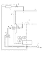
図1は本発明の構成例1を示すオゾンガス殺菌装置の概略構成図である。 FIG. 1 is a schematic configuration diagram of an ozone gas sterilizer showing a configuration example 1 of the present invention.
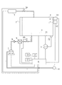
図2は本発明の構成例2を示すオゾンガス殺菌装置の概略構成図である。 Figure 2 is a schematic diagram of an ozone gas disinfection apparatus according to the configuration example 2 of the present invention.
図3は本発明の実施例1及び実施例2を示すオゾンガス殺菌装置の概略構成図である。
FIG. 3 is a schematic configuration diagram of an ozone gas sterilizer showing Embodiment 1 and
まず、本発明の構成例1であるオゾンガス殺菌装置の全体構成について、図1を参照にして説明する。 First, the whole structure of the ozone gas sterilizer which is the structural example 1 of this invention is demonstrated with reference to FIG.
図1に示すように、殺菌庫1はオゾンガス庫本体であり、該殺菌庫1には被殺菌処理対象物を内部に設置及び搬出するときに使用する開閉用扉2が設けられている。
As shown in FIG. 1, the sterilization chamber 1 is an ozone gas storage body, and the sterilization chamber 1 is provided with an opening /
オゾンガス発生装置3は、電磁切替弁20を介して殺菌庫1に配管等を介して連通されている。
The ozone gas generator 3 is communicated with the sterilizer 1 via a pipe or the like via an
排気装置7は、チェック弁8、排ガス無害化装置9、電磁切替弁18を介して、殺菌庫1、排気口10にそれぞれ配管等を介して連通されている。
The exhaust device 7 is communicated with the sterilizer 1 and the
排気装置7としては、真空ポンプなどが挙げられる。 Examples of the exhaust device 7 include a vacuum pump.
オゾン検出器4は、殺菌庫1内に設置されている。 The ozone detector 4 is installed in the sterilizer 1.
なお、オゾン検出器4に替えて、オゾンガス濃度計を殺菌庫1の外部に設置し、配管等を介して殺菌庫1と連通させてもよい。 Instead of the ozone detector 4, an ozone gas concentration meter may be installed outside the sterilizer 1 and communicated with the sterilizer 1 via a pipe or the like.
電磁切替弁18・20、オゾンガス発生装置3、オゾン検出器4、排気装置7、排ガス無害化装置9、操作手段13、出力手段14、表示手段15は、コントロールユニット6と接続されている。出力手段14としては、プリンタなどが挙げられる。
The
コントロールユニット6は中央演算処理装置(CPU)や記憶装置(RAMやROM)やインターフェース等からなり、ROMに後述する制御プログラム及び演算プログラムが記憶されている。
The
次に、上記構成の作用について説明する。 Next, the operation of the above configuration will be described.
まず、被殺菌処理対象物を殺菌庫1に収納して扉2を閉め、殺菌庫1を密閉する。スイッチ等の操作手段13をオンすると、表示手段15に殺菌中であることが表示され、コントロールユニット6により次の制御が行われる。つまり、排気用電磁切替弁18を開とし、排気装置7を作動させて殺菌庫1内の雰囲気ガスが排気される。そして、オゾンガス発生装置3において無声放電などのオゾンガス機構により、オゾンガスが生成され、電磁切替弁20を介して殺菌庫1内へ送られ、殺菌庫1内にオゾンガスが充満し、被殺菌処理対象物の殺菌処理がなされる。該注入工程におけるオゾンガス発生装置3からの、オゾンガス注入量、注入時間、注入繰り返し回数などは、殺菌庫の大きさ、必要とされる効果により設定を行う。殺菌処理中に設定値以外のオゾン濃度がオゾン検出器4より検知されれば、設定値になるように、オゾンガス注入量、注入時間、注入繰り返し回数などが操作される。そして、殺菌後の残留オゾンガスは、排気装置7により、電磁切替弁18、排ガス無害化装置9、チェック弁8を介して無害化された後、排気される。このオゾンガス排気工程が終了すると表示手段15にその旨が表示され、殺菌庫用扉2を開とし、被殺菌処理対象物を取り出す。前述のオゾンガス注入工程からオゾンガス排出工程までのすべての工程における殺菌庫1内のオゾン濃度は、オゾン検出器4により検知され、出力手段14より出力される。
First, the object to be sterilized is stored in the sterilizer 1, the
このように、被殺菌処理対象物を内部に収納する殺菌庫と、殺菌庫内にオゾンガスを供給する機構と、内部にガスが浸透しにくい被殺菌処理対象物にオゾンガスを浸透させる機構とを有するオゾンガスを用いたオゾンガス殺菌装置において、殺菌庫内のオゾン濃度を検知する機構と、その検知結果に基づいて該オゾン濃度を制御する機構と、該制御状況を出力する制御状況出力手段とを設けたことにより、殺菌処理工程中の殺菌庫内のオゾン濃度を設定値に制御できると共に、該オゾン濃度が出力手段より出力されることにより殺菌庫内のオゾン濃度が設定値に制御されていたことを保証することができるので、効率的で確実に殺菌作業が行える。 Thus, the sterilization box for accommodating the article to be sterilized object inside, a mechanism for supplying ozone gas into the sterilization chamber, a mechanism for infiltrating ozone gas to be sterilized object gas is difficult to permeate into the In an ozone gas sterilizer using ozone gas having a mechanism, a mechanism for detecting the ozone concentration in the sterilization chamber, a mechanism for controlling the ozone concentration based on the detection result, and a control status output means for outputting the control status By providing, the ozone concentration in the sterilization chamber during the sterilization treatment process can be controlled to the set value, and the ozone concentration in the sterilization chamber was controlled to the set value by outputting the ozone concentration from the output means. So that the sterilization can be performed efficiently and reliably.
また、前記オゾンガス殺菌装置のオゾン濃度を制御する機構が、殺菌庫1内のオゾン濃度を制御する際、オゾンガス発生装置3からのガスの発生量を一定として、注入時間のみを操作対象とすることにより、シンプルな構成で制御できる。 Further, when the mechanism for controlling the ozone concentration of the ozone gas sterilizer controls the ozone concentration in the sterilizer 1, the amount of gas generated from the ozone gas generator 3 is made constant and only the injection time is set as the operation target. Therefore, it can be controlled with a simple configuration.
次に、構成例2について、図2により説明を行う。本構成例2で示すオゾンガス殺菌装置の全体構成は、構成例1で示した全体構成に一部装置・配管類を追加したものであり、差圧検知器5と第一圧力検知器21と第二圧力検知器22と供給ユニット11と排気ユニット12とHEPAフィルタ(エアフィルタ)16・17とを設けている。差圧検知器5は、殺菌庫1内に設置された第一圧力検知器21及び庫外に設置された第二圧力検知器22と接続されている。供給ユニット11は、HEPAフィルタ16を介して殺菌庫1にそれぞれ配管等を介して連通されている。排気ユニット12は、HEPAフィルタ17を介して殺菌庫1にそれぞれ配管等を介して連通されている。差圧検知器5、供給ユニット11、排気ユニット12は、コントロールユニット6と接続されている。
Next, Configuration Example 2 will be described with reference to FIG. The overall configuration of the ozone gas sterilizer shown in Configuration Example 2 is obtained by adding some devices and piping to the overall configuration shown in Configuration Example 1 , and includes a differential pressure detector 5, a
まず、構成例1と同様に被殺菌処理対象物を殺菌庫1に収納して扉2を閉め、殺菌庫1を密閉する。スイッチ等の操作手段13をオンすると、表示手段15に殺菌中であることが表示され、前記オゾンガス注入工程が行われる。そして、差圧検知器5により、殺菌庫1内の圧力と大気圧との差圧が検知される。つまり、第一圧力検知器21の信号と、第二圧力検知器の信号とがそれぞれ差圧検知器5に入力され、該差圧検知器5により殺菌庫1内部と大気圧との差圧が求められる。そして、コントロールユニット6により該差圧が設定値になるよう殺菌庫1内の圧力が制御される。つまり、殺菌庫1内の圧力が陽圧(大気圧よりも高い圧)になるように差圧を設定していた場合において、陰圧と検知された場合は、給気ユニット11が作動して、殺菌庫1内に庫外の雰囲気ガスが給気される。殺菌庫1内の圧力が陰圧(大気圧よりも低い圧)になるように差圧を設定していた場合において、陽圧と検知された場合は、排気ユニット12が作動して、殺菌庫1内の雰囲気ガスが排気される。殺菌庫1内の圧力を陽圧から陰圧へ変化させるように差圧を設定していた場合は、適宜前記給気工程、排気工程が行われる。そして、殺菌後の残留オゾンガスは、排気装置7により、電磁切替弁18、排ガス無害化装置9、チェック弁8を介して無害化された後、排気される。このオゾンガス排気工程が終了すると表示手段15にその旨が表示され、殺菌庫用扉2を開とし、被殺菌処理対象物を取り出す。前述のオゾンガス注入工程からオゾンガス排出工程までのすべての工程における殺菌庫1内の圧力と大気圧との差圧は、差圧検知器5により検知され、出力手段14より出力される。
First, similarly to the configuration example 1 , the object to be sterilized is stored in the sterilizer 1, the
このように、オゾンガスを用いたオゾンガス殺菌装置において、殺菌庫外の雰囲気ガスを殺菌庫内に供給する機構と、殺菌庫内の雰囲気ガスを殺菌庫外に排気する機構とを設けたことにより、殺菌庫内にオゾンガスと共に殺菌庫外の雰囲気ガスを導入できるので、導入ガス量を増加させることができ、オゾン濃度の立上り時間を短縮して殺菌を効率的に行うことができる。 Thus, in the ozone gas sterilization apparatus using ozone gas, by providing a mechanism for supplying atmospheric gas outside the sterilization chamber into the sterilization chamber and a mechanism for exhausting the atmospheric gas inside the sterilization chamber to the outside of the sterilization chamber, Since the atmospheric gas outside the sterilization chamber can be introduced into the sterilization chamber together with the ozone gas, the amount of the introduced gas can be increased, and the rise time of the ozone concentration can be shortened to perform the sterilization efficiently.
また、前記オゾンガス殺菌装置において、殺菌庫内と殺菌庫外との差圧を検知する機構と、その検知結果に基づいて殺菌庫内の圧力を制御する機構と、その制御状況を出力する制御状況出力手段とを設けたことにより、殺菌処理工程中の殺菌庫内の圧力と大気圧との差圧を設定値に制御できると共に、該差圧が出力手段より出力されることにより殺菌庫内の圧力が設定値に制御されていたことを保証することができ、確実に殺菌作業が行える。 In the ozone gas sterilizer , a mechanism for detecting a differential pressure between the inside and outside of the sterilizer, a mechanism for controlling the pressure in the sterilizer based on the detection result, and a control status for outputting the control status By providing the output means, the differential pressure between the pressure in the sterilization chamber and the atmospheric pressure during the sterilization process can be controlled to a set value, and the differential pressure is output from the output means to It can be assured that the pressure is controlled to the set value, and the sterilization operation can be performed reliably.
また、前記オゾンガス殺菌装置において、殺菌庫内の圧力が陽圧になるように差圧を設定する場合、殺菌処理中に菌やバクテリアなど有害な微生物が存在する恐れのある殺菌庫外の雰囲気ガスが、殺菌庫内に侵入することを防止できると共に、殺菌庫内と殺菌庫外との差圧が出力手段より出力されるので、殺菌庫内の圧力が陽圧に維持できていたこと及び殺菌庫外の雰囲気ガスの浸入がなく、殺菌庫内の清浄度が保持されていることを保証することができる。 In the ozone gas sterilizer , when the differential pressure is set so that the pressure in the sterilization chamber becomes positive, the atmospheric gas outside the sterilization chamber may contain harmful microorganisms such as bacteria and bacteria during the sterilization treatment. Can be prevented from entering the sterilization chamber, and the differential pressure between the sterilization chamber and the outside of the sterilization chamber is output from the output means. It is possible to ensure that the atmosphere inside the sterilization chamber is kept clean without the intrusion of atmospheric gas outside the chamber.
また、前記オゾンガス殺菌装置において、殺菌庫内の圧力が陰圧になるように差圧を設定する場合、殺菌庫内に設置した被殺菌処理対象物が汚染されている場合に、殺菌庫内を陰圧に維持することにより、殺菌庫内の汚染された恐れのある雰囲気ガスが庫外に排気されるのを防止することができると共に、殺菌庫内と殺菌庫外との差圧が出力手段より出力されるので、殺菌庫内の圧力が陰圧に維持できていたこと及び汚染された殺菌庫内の雰囲気ガスが殺菌庫外に漏れていないことを保証することにより、殺菌庫外の汚染が無いことを保証することができ、安全に殺菌作業が行える。 Further, in the ozone gas sterilizer , when the differential pressure is set so that the pressure in the sterilization chamber becomes negative, the sterilization chamber is contaminated when the object to be sterilized installed in the sterilization chamber is contaminated. By maintaining the negative pressure, it is possible to prevent the atmospheric gas that may have been contaminated in the sterilization chamber from being exhausted to the outside, and the differential pressure between the sterilization chamber and the outside of the sterilization chamber is output means. As a result, it is possible to maintain the negative pressure inside the sterilizer and to ensure that the atmospheric gas inside the contaminated sterilizer does not leak out of the sterilizer. It can be ensured that there is no sterilization, and sterilization can be performed safely.
また、前記オゾンガス殺菌装置において、殺菌庫内の圧力を陰圧から陽圧へ変化させるように差圧を設定する場合、殺菌処理中に殺菌庫内の圧力を変化させて、被殺菌処理対象物に隅々までオゾンガスを浸透させることができると共に、被殺菌処理対象物に付着した細菌に対し、環境条件の変化をもたらし、殺菌効果を上げることができる。また、殺菌庫内と殺菌庫外との差圧が出力手段より出力されるので、差圧が設定値に維持されていたことを保証することができる。 In the ozone gas sterilization apparatus , when setting the differential pressure so that the pressure in the sterilization chamber is changed from negative pressure to positive pressure, the pressure in the sterilization chamber is changed during the sterilization processing, In addition, ozone gas can be permeated to every corner, and environmental conditions can be changed for bacteria attached to the object to be sterilized, thereby improving the sterilizing effect. Moreover, since the differential pressure between the inside of the sterilization chamber and the outside of the sterilization chamber is output from the output means, it can be ensured that the differential pressure is maintained at the set value.
また、前記オゾンガス殺菌装置において、殺菌庫外の雰囲気ガスを殺菌庫内に供給する機構(供給ユニット11)のガス通路にHEPAフィルタを設置したことにより、殺菌庫内に設置した被殺菌処理対象物を殺菌する場合において、殺菌庫内の圧力が低くなりすぎた場合等、庫内に給気を行う必要が生じた場合においても、庫内に大気中に存在する微粒子や有害な微生物などが浸入するのを防止することができる。また、殺菌庫内の雰囲気ガスを殺菌庫外に排気する機構(排気ユニット12)のガス通路にHEPAフィルタを設置したことにより、殺菌庫内が汚染されている恐れがある場合などにおいて、殺菌庫内の圧力が高すぎた場合など庫外に庫内の雰囲気ガスを排気する必要が生じた場合においても、庫内の汚染された空気をフィルタリングして庫外に排気することができる。 In the ozone gas sterilizer , the HEPA filter is installed in the gas passage of the mechanism (supply unit 11) for supplying the atmospheric gas outside the sterilizer into the sterilizer, so that the object to be sterilized installed in the sterilizer is installed. Even when it is necessary to supply air to the sterilization chamber, such as when the pressure in the sterilization chamber becomes too low, fine particles or harmful microorganisms in the atmosphere enter the chamber. Can be prevented. Further, when the HEPA filter is installed in the gas passage of the mechanism (exhaust unit 12) for exhausting the atmospheric gas in the sterilization chamber to the outside, the sterilization chamber may be contaminated. Even when it is necessary to exhaust the atmospheric gas in the storage outside the storage, such as when the internal pressure is too high, the contaminated air in the storage can be filtered and exhausted outside the storage.
次に、実施例1について、図3により説明を行う。本実施例1で示すオゾンガス殺菌装置の全体構成は、構成例2で示した全体構成に一部装置・配管類を追加したものであり、記録手段19と警報装置23とを設けている。記録手段19、警報装置23は、コントロールユニット6と接続されている。
Next, Example 1 will be described with reference to FIG. The overall configuration of the ozone gas sterilization apparatus shown in the first embodiment is obtained by adding some devices and piping to the entire configuration shown in the configuration example 2 , and includes a
まず、構成例1と同様に被殺菌処理対象物を殺菌庫1に収納して扉2を閉め、殺菌庫1を密閉する。スイッチ等の操作手段13をオンすると、表示手段15に殺菌中であることが表示され、前記オゾンガス注入工程が行われる。そして、殺菌庫1内にオゾンガスが充満し、被殺菌処理対象物の殺菌処理がなされる。注入工程におけるオゾンガス注入量、注入時間、注入繰り返し回数などは、殺菌庫の大きさ、必要とされる効果により設定を行う。殺菌処理工程終了後は、オゾン検出器4で検知された殺菌処理を行った殺菌庫1内のオゾン濃度と該殺菌処理にかかった時間との積がコントロールユニット16のROMに記憶されたプログラムにて算出される。そして、該算出結果は、殺菌効果指標値として表示手段15に表示されると共に、記録手段19に記録される。そして、該殺菌効果指標値と予め設定された殺菌効果指標値とを比較し、設定値を下回るときは、前記オゾン殺菌作業を開始する。設定値を上回るときは、前記オゾンガス排気工程に移行する。
First, similarly to the configuration example 1 , the object to be sterilized is stored in the sterilizer 1, the
このように、前記オゾンガス殺菌装置において、殺菌処理を行った殺菌庫内のオゾン濃度と該殺菌処理にかかった時間との積を算出する算出手段と、該算出結果を殺菌効果指標値として表示する表示手段及び記録する記録手段とを設けたことにより、通常数日間の菌の培養が必要な為、オンラインで直接確認することができない殺菌効果をオゾン濃度と処理時間との積という形で算出、表示、記録することができ、オンラインで殺菌保証が可能となり、確実に殺菌作業が行える。 Thus, in the ozone gas sterilizer , the calculation means for calculating the product of the ozone concentration in the sterilization chamber that has been sterilized and the time taken for the sterilization process, and the calculation result are displayed as the sterilization effect index value. By providing display means and recording means for recording, it is usually necessary to culture bacteria for several days, so the bactericidal effect that cannot be confirmed directly online is calculated in the form of the product of ozone concentration and treatment time, It can be displayed and recorded, sterilization can be guaranteed online, and sterilization can be performed reliably.
また、前記オゾンガス殺菌装置において、算出された殺菌効果指標値が予め設定された殺菌効果指標値に達しない場合には殺菌処理を再開することにより、不十分な殺菌効果のまま殺菌処理が終了することを防止することができ、所望の殺菌効果を確保できる。 Further, in the ozone gas sterilizer , when the calculated sterilization effect index value does not reach a preset sterilization effect index value, the sterilization process is completed by restarting the sterilization process with an insufficient sterilization effect. This can be prevented, and a desired sterilizing effect can be secured.
次に、実施例2について、図3により説明を行う。まず、構成例1と同様に被殺菌処理対象物を殺菌庫1に収納して扉2を閉め、殺菌庫1を密閉する。スイッチ等の操作手段13をオンすると、表示手段15に殺菌中であることが表示され、前記オゾンガス注入工程が行われる。そして、殺菌処理開始から所定時間内における殺菌庫1内のオゾン濃度の上昇変化(オゾン濃度上昇勾配)がコントロールユニット16のROMに記憶されたプログラムにて算出される。そして、所定時間内に、該オゾン濃度上昇勾配が予め設定された勾配を下回るときは、警報装置23より警報が発せられ、殺菌処理工程は終了し、前記オゾンガス排出工程に移行する。
Next, Example 2 will be described with reference to FIG. First, similarly to the configuration example 1, the object to be sterilized is stored in the sterilizer 1, the
このように、前記オゾンガス殺菌装置において、オゾン濃度上昇勾配を算出する算出手段と、警報信号を警報装置に出力する出力手段とを備え、所定時間内にオゾン濃度上昇勾配が設定値以下になったとき、オゾンガス殺菌装置の運転を自動的に停止すると共に、警報することにより、不十分な殺菌効果のまま殺菌処理が終了することを防止することができる。これは被殺菌処理対象物の違いにより、オゾン濃度上昇勾配が異なることに着目したもので、設定した勾配と実測した勾配とを比較し、設定値を下回るときは殺菌装置の処理可能容量を超過することになるため、前記措置をとることとしたものである。 As described above, the ozone gas sterilizer includes a calculation unit that calculates an ozone concentration increase gradient and an output unit that outputs an alarm signal to the alarm device, and the ozone concentration increase gradient becomes equal to or less than a set value within a predetermined time. When the operation of the ozone gas sterilizer is automatically stopped and an alarm is issued, it is possible to prevent the sterilization process from being completed with an insufficient sterilization effect. This is focused on the difference in the ozone concentration increase gradient depending on the object to be sterilized. Compare the set gradient with the measured gradient, and if it falls below the set value, the sterilizer capacity exceeds the processing capacity. Therefore, the above measures are taken.
構成例1及至実施例2において殺菌ガスとして使用するガスは、オゾンガスに限定するものである。The gas used as the sterilizing gas in Configuration Example 1 to Example 2 is limited to ozone gas.
以上のように、被殺菌処理対象物を内部に収納する殺菌庫と、殺菌庫内にオゾンガスを供給する機構と、内部にガスが浸透しにくい被殺菌処理対象物にオゾンガスを浸透させる機構とを有するオゾンガスを用いたオゾンガス殺菌装置において、殺菌庫内のオゾン濃度を検知する機構と、その検知結果に基づいて該オゾン濃度を制御する機構と、該制御状況を出力する制御状況出力手段とを設けたことにより、殺菌処理工程中の殺菌庫内のオゾン濃度を設定値に制御できると共に、該オゾン濃度が出力手段より出力されることにより殺菌庫内のオゾン濃度が設定値に制御されていたことを保証することができるので、効率的で確実に殺菌作業が行える。 As described above, the sterilization box for accommodating the article to be sterilized object inside, a mechanism for supplying ozone gas into the sterilization chamber, a mechanism for infiltrating ozone gas to be sterilized object gas is difficult to permeate into the In an ozone gas sterilizer using ozone gas having a mechanism, a mechanism for detecting the ozone concentration in the sterilization chamber, a mechanism for controlling the ozone concentration based on the detection result, and a control status output means for outputting the control status By providing, the ozone concentration in the sterilization chamber during the sterilization treatment process can be controlled to the set value, and the ozone concentration in the sterilization chamber was controlled to the set value by outputting the ozone concentration from the output means. So that the sterilization can be performed efficiently and reliably.
また、前記オゾンガス殺菌装置のオゾン濃度を制御する機構が、殺菌庫1内のオゾン濃度を制御する際、オゾンガス発生装置3からのガスの発生量を一定として、注入時間のみを操作対象とすることにより、シンプルな構成で制御できる。 Further, when the mechanism for controlling the ozone concentration of the ozone gas sterilizer controls the ozone concentration in the sterilizer 1, the amount of gas generated from the ozone gas generator 3 is made constant and only the injection time is set as the operation target. Therefore, it can be controlled with a simple configuration.
また、オゾンガスを用いたオゾンガス殺菌装置において、殺菌庫外の雰囲気ガスを殺菌庫内に供給する機構と、殺菌庫内の雰囲気ガスを殺菌庫外に排気する機構とを設けたことにより、殺菌庫内にオゾンガスと共に殺菌庫外の雰囲気ガスを導入できるので、導入ガス量を増加させることができ、オゾン濃度の立上り時間を短縮して殺菌を効率的に行うことができる。 Further, in the ozone gas sterilizer using ozone gas, a sterilizer is provided by providing a mechanism for supplying atmospheric gas outside the sterilizer into the sterilizer and a mechanism for exhausting atmospheric gas inside the sterilizer outside the sterilizer. Since the atmospheric gas outside the sterilization chamber can be introduced into the inside together with the ozone gas, the amount of the introduced gas can be increased, and the rise time of the ozone concentration can be shortened to efficiently perform sterilization.
また、前記オゾンガス殺菌装置において、殺菌庫内と殺菌庫外との差圧を検知する機構と、その検知結果に基づいて殺菌庫内の圧力を制御する機構と、その制御状況を出力する制御状況出力手段とを設けたことにより、殺菌処理工程中の殺菌庫内の圧力と大気圧との差圧を設定値に制御できると共に、該差圧が出力手段より出力されることにより殺菌庫内の圧力が設定値に制御されていたことを保証することができ、確実に殺菌作業が行える。 In the ozone gas sterilizer , a mechanism for detecting a differential pressure between the inside and outside of the sterilizer, a mechanism for controlling the pressure in the sterilizer based on the detection result, and a control status for outputting the control status By providing the output means, the differential pressure between the pressure in the sterilization chamber and the atmospheric pressure during the sterilization process can be controlled to a set value, and the differential pressure is output from the output means to It can be assured that the pressure is controlled to the set value, and the sterilization operation can be performed reliably.
また、前記オゾンガス殺菌装置において、殺菌庫内の圧力が陽圧になるように差圧を設定する場合、殺菌処理中に菌やバクテリアなど有害な微生物が存在する恐れのある殺菌庫外の雰囲気ガスが、殺菌庫内に侵入することを防止できると共に、殺菌庫内と殺菌庫外との差圧が出力手段より出力されるので、殺菌庫内の圧力が陽圧に維持できていたこと及び殺菌庫外の雰囲気ガスの浸入がなく、殺菌庫内の清浄度が保持されていることを保証することができる。 Further, the Oite the ozone sterilizer, the pressure in the sterilization chamber may set the differential pressure to be a positive pressure, sterilization chamber outside of which may be present harmful microorganisms such as fungi and bacteria during sterilization Atmospheric gas can be prevented from entering the sterilization chamber, and the differential pressure between the sterilization chamber and the outside of the sterilization chamber is output from the output means, so the pressure inside the sterilization chamber was maintained at a positive pressure. Moreover, there is no intrusion of atmospheric gas outside the sterilization chamber, and it can be ensured that the cleanliness inside the sterilization chamber is maintained.
また、前記オゾンガス殺菌装置において、殺菌庫内の圧力が陰圧になるように差圧を設定する場合、殺菌庫内に設置した被殺菌処理対象物が汚染されている場合に、殺菌庫内を陰圧に維持することにより、殺菌庫内の汚染された恐れのある雰囲気ガスが庫外に排気されるのを防止することができると共に、殺菌庫内と殺菌庫外との差圧が出力手段より出力されるので、殺菌庫内の圧力が陰圧に維持できていたこと及び汚染された殺菌庫内の雰囲気ガスが殺菌庫外に漏れていないことを保証することにより、殺菌庫外の汚染が無いことを保証することができ、安全に殺菌作業が行える。 Further, in the ozone gas sterilizer , when the differential pressure is set so that the pressure in the sterilization chamber becomes negative, the sterilization chamber is contaminated when the object to be sterilized installed in the sterilization chamber is contaminated. By maintaining the negative pressure, it is possible to prevent the atmospheric gas that may have been contaminated in the sterilization chamber from being exhausted to the outside, and the differential pressure between the sterilization chamber and the outside of the sterilization chamber is output means. As a result, it is possible to maintain the negative pressure inside the sterilizer and to ensure that the atmospheric gas inside the contaminated sterilizer does not leak out of the sterilizer. It can be ensured that there is no sterilization, and sterilization can be performed safely.
また、前記オゾンガス殺菌装置において、殺菌庫内の圧力を陰圧から陽圧へ変化させるように差圧を設定する場合、殺菌処理中に殺菌庫内の圧力を変化させて、被殺菌処理対象物に隅々までオゾンガスを浸透させることができると共に、被殺菌処理対象物に付着した細菌に対し、環境条件の変化をもたらし、殺菌効果を上げることができる。また、殺菌庫内と殺菌庫外との差圧が出力手段より出力されるので、差圧が設定値に維持されていたことを保証することができる。 In the ozone gas sterilization apparatus , when setting the differential pressure so that the pressure in the sterilization chamber is changed from negative pressure to positive pressure, the pressure in the sterilization chamber is changed during the sterilization processing, In addition, ozone gas can be permeated to every corner, and environmental conditions can be changed for bacteria attached to the object to be sterilized, thereby improving the sterilizing effect. Moreover, since the differential pressure between the inside of the sterilization chamber and the outside of the sterilization chamber is output from the output means, it can be ensured that the differential pressure is maintained at the set value.
また、前記オゾンガス殺菌装置において、殺菌庫外の雰囲気ガスを殺菌庫内に供給する機構(供給ユニット11)のガス通路にHEPAフィルタ等のエアフィルタを設置したことにより、殺菌庫内に設置した被殺菌処理対象物を殺菌する場合において、殺菌庫内の圧力が低くなりすぎた場合等、庫内に給気を行う必要が生じた場合においても、庫内に大気中に存在する微粒子や有害な微生物などが浸入するのを防止することができる。また、殺菌庫内の雰囲気ガスを殺菌庫外に排気する機構(排気ユニット12)のガス通路にHEPAフィルタ等のエアフィルタを設置したことにより、殺菌庫内が汚染されている恐れがある場合などにおいて、殺菌庫内の圧力が高すぎた場合など庫外に庫内の雰囲気ガスを排気する必要が生じた場合においても、庫内の汚染された空気をフィルタリングして庫外に排気することができる。 In the ozone gas sterilizer , an air filter such as a HEPA filter is installed in the gas passage of the mechanism (supply unit 11) for supplying atmospheric gas outside the sterilizer into the sterilizer. When sterilizing an object to be sterilized, when the pressure in the sterilization chamber becomes too low, etc., even if it is necessary to supply air to the chamber, fine particles present in the chamber or harmful It is possible to prevent infiltration of microorganisms and the like. In addition, when an air filter such as a HEPA filter is installed in the gas passage of the mechanism (exhaust unit 12) for exhausting the atmospheric gas in the sterilization chamber to the outside, the sterilization chamber may be contaminated. In the case where it is necessary to exhaust the atmospheric gas in the storage outside the storage, such as when the pressure in the sterilization storage is too high, the contaminated air in the storage can be filtered and exhausted outside the storage. it can.
また、オゾンガスを用いたオゾンガス殺菌装置において、殺菌処理を行った殺菌庫内のオゾン濃度と該殺菌処理にかかった時間との積を算出する算出手段と、該算出結果を殺菌効果指標置として表示する表示手段及び記録する記録手段とを設けたことにより、通常数日間の菌の培養が必要な為、オンラインで直接確認することができない殺菌効果をオゾン濃度と処理時間との積という形で算出、表示、記録することができ、オンラインで殺菌保証が可能となり、確実に殺菌作業が行える。 In addition, in the ozone gas sterilizer using ozone gas, a calculation means for calculating the product of the ozone concentration in the sterilization chamber where the sterilization process is performed and the time taken for the sterilization process, and the calculation result are displayed as a sterilization effect indicator. By providing display means for recording and recording means for recording, it is usually necessary to culture bacteria for several days, so the bactericidal effect that cannot be confirmed directly online is calculated in the form of the product of ozone concentration and treatment time Can be displayed, recorded, sterilization can be guaranteed online, and sterilization can be performed reliably.
また、前記オゾンガス殺菌装置において、算出された殺菌効果指標値が予め設定された殺菌効果指標値に達しない場合には殺菌処理を再開することにより、不十分な殺菌効果のまま殺菌処理が終了することを防止することができ、所望の殺菌効果を確保できる。 Further, in the ozone gas sterilizer , when the calculated sterilization effect index value does not reach a preset sterilization effect index value, the sterilization process is completed by restarting the sterilization process with an insufficient sterilization effect. This can be prevented, and a desired sterilizing effect can be secured.
また、オゾンガスを用いたオゾンガス殺菌装置において、殺菌庫内のオゾン濃度上昇勾配を算出する算出手段と、警報信号を警報装置に出力する出力手段とを備え、所定時間内にオゾン濃度上昇勾配が設定値以下になったとき、オゾンガス殺菌装置の運転を自動的に停止すると共に、警報することにより、不十分な殺菌効果のまま殺菌処理が終了することを防止することができる。 In addition, the ozone gas sterilizer using ozone gas comprises a calculating means for calculating the ozone concentration increase gradient in the sterilization chamber and an output means for outputting an alarm signal to the alarm device, and the ozone concentration increase gradient is set within a predetermined time. When the ozone gas sterilization apparatus is not more than the value, the operation of the ozone gas sterilizer is automatically stopped and an alarm can be given to prevent the sterilization process from being completed with an insufficient sterilization effect.
1 殺菌庫
2 殺菌庫用扉
3 オゾンガス発生装置
4 オゾン検出器
5 差圧検知器
6 コントロールユニット
11 供給ユニット
12 排気ユニット
14 出力手段
15 表示手段
16 HEPAフィルタ
17 HEPAフィルタ
19 記録手段
23 警報装置
DESCRIPTION OF SYMBOLS 1
Claims (1)
Priority Applications (1)
| Application Number | Priority Date | Filing Date | Title |
|---|---|---|---|
| JP2007022212A JP4773986B2 (en) | 2007-01-31 | 2007-01-31 | Ozone gas sterilizer |
Applications Claiming Priority (1)
| Application Number | Priority Date | Filing Date | Title |
|---|---|---|---|
| JP2007022212A JP4773986B2 (en) | 2007-01-31 | 2007-01-31 | Ozone gas sterilizer |
Publications (2)
| Publication Number | Publication Date |
|---|---|
| JP2008188043A JP2008188043A (en) | 2008-08-21 |
| JP4773986B2 true JP4773986B2 (en) | 2011-09-14 |
Family
ID=39748716
Family Applications (1)
| Application Number | Title | Priority Date | Filing Date |
|---|---|---|---|
| JP2007022212A Active JP4773986B2 (en) | 2007-01-31 | 2007-01-31 | Ozone gas sterilizer |
Country Status (1)
| Country | Link |
|---|---|
| JP (1) | JP4773986B2 (en) |
Families Citing this family (6)
| Publication number | Priority date | Publication date | Assignee | Title |
|---|---|---|---|---|
| JP5538037B2 (en) * | 2010-04-06 | 2014-07-02 | 株式会社タムラテコ | Ozone sterilization management device |
| JP2011218094A (en) * | 2010-04-14 | 2011-11-04 | Tamura Teco:Kk | Ozone sterilization testing equipment |
| JP5620192B2 (en) * | 2010-08-18 | 2014-11-05 | 株式会社Ihiシバウラ | Ozone gas sterilizer |
| JP6966077B2 (en) * | 2018-09-13 | 2021-11-10 | サクラエスアイ株式会社 | Gas sterilizer |
| TW202218696A (en) * | 2020-10-02 | 2022-05-16 | 日商新田股份有限公司 | Decontamination apparatus and decontamination method |
| WO2022208842A1 (en) * | 2021-04-01 | 2022-10-06 | 三菱電機株式会社 | Sterilization device and sterilization method |
Family Cites Families (7)
| Publication number | Priority date | Publication date | Assignee | Title |
|---|---|---|---|---|
| US5882590A (en) * | 1996-07-03 | 1999-03-16 | American Sterilizer Company | Monitoring and control of sterilization processes with semiconductor sensor modules |
| JPH10258113A (en) * | 1997-03-18 | 1998-09-29 | Miura Co Ltd | Sterilization method using ozone |
| JP3824748B2 (en) * | 1997-09-08 | 2006-09-20 | 瑞穂医科工業株式会社 | Chamber ozone sterilization system |
| JP2001349586A (en) * | 2000-06-08 | 2001-12-21 | Bio Media Co Ltd | Room pressure adjusting apparatus |
| CN1665548A (en) * | 2002-05-01 | 2005-09-07 | 斯玛特空气设备株式会社 | Air sterilizer using ozone |
| JP2004152007A (en) * | 2002-10-30 | 2004-05-27 | Hokoku Kogyo Co Ltd | Ozone generation device and vending machine incorporating same device |
| JP4052320B2 (en) * | 2005-06-02 | 2008-02-27 | 株式会社Ihi | Sterilizer |
-
2007
- 2007-01-31 JP JP2007022212A patent/JP4773986B2/en active Active
Also Published As
| Publication number | Publication date |
|---|---|
| JP2008188043A (en) | 2008-08-21 |
Similar Documents
| Publication | Publication Date | Title |
|---|---|---|
| JP4773982B2 (en) | Sterilization gas infiltration device | |
| JP4773986B2 (en) | Ozone gas sterilizer | |
| JP4924570B2 (en) | Isolator system | |
| KR20120028413A (en) | Sterilizing apparatus using hydrogen peroxide, ozone and cold plasma and method therefor | |
| JP4447013B2 (en) | Apparatus and method for humidifying a sterilization chamber | |
| KR101215928B1 (en) | Sterilizing apparatus using ozone and method therefor | |
| JP2015123162A (en) | Decontamination processor and decontamination method | |
| CN205814729U (en) | A kind of ozone sterilization-box under common temperature | |
| AU2016200736B2 (en) | Method and device for hydrogen peroxide sterilization | |
| US11759537B2 (en) | Sterilizing method and sterilizer | |
| JP5410007B2 (en) | Isolator | |
| US20230115895A1 (en) | Sterilizing method and sterilizer | |
| JP5074330B2 (en) | Prefilled syringe decontamination method | |
| JP2007167546A (en) | Method and device for gas-sterilizing narrow tube part | |
| JP4963594B2 (en) | Sterilizer | |
| US11766494B2 (en) | Sterilizing method and sterilizer | |
| US11766497B2 (en) | Sterilizing method and sterilizer | |
| US20230141766A1 (en) | Sterilizing method and sterilizer | |
| JP2015231409A (en) | Hydrogen peroxide gas sterilizer | |
| JP7547754B2 (en) | Sterilization Equipment | |
| JP5192184B2 (en) | Sterilization method and apparatus | |
| JP2012061044A (en) | Gas sterilization apparatus | |
| JP2012035013A (en) | Gas sterilization apparatus | |
| JP2007185275A (en) | Residual gas removal method in gas sterilization | |
| JP2010234067A (en) | Gas sterilization, pasteurization method and device of capillary part |
Legal Events
| Date | Code | Title | Description |
|---|---|---|---|
| A621 | Written request for application examination |
Free format text: JAPANESE INTERMEDIATE CODE: A621 Effective date: 20091221 |
|
| A977 | Report on retrieval |
Free format text: JAPANESE INTERMEDIATE CODE: A971007 Effective date: 20110203 |
|
| A131 | Notification of reasons for refusal |
Free format text: JAPANESE INTERMEDIATE CODE: A131 Effective date: 20110222 |
|
| A521 | Request for written amendment filed |
Free format text: JAPANESE INTERMEDIATE CODE: A523 Effective date: 20110407 |
|
| A131 | Notification of reasons for refusal |
Free format text: JAPANESE INTERMEDIATE CODE: A131 Effective date: 20110426 |
|
| A521 | Request for written amendment filed |
Free format text: JAPANESE INTERMEDIATE CODE: A523 Effective date: 20110602 |
|
| TRDD | Decision of grant or rejection written | ||
| A01 | Written decision to grant a patent or to grant a registration (utility model) |
Free format text: JAPANESE INTERMEDIATE CODE: A01 Effective date: 20110621 |
|
| A01 | Written decision to grant a patent or to grant a registration (utility model) |
Free format text: JAPANESE INTERMEDIATE CODE: A01 |
|
| A61 | First payment of annual fees (during grant procedure) |
Free format text: JAPANESE INTERMEDIATE CODE: A61 Effective date: 20110624 |
|
| FPAY | Renewal fee payment (event date is renewal date of database) |
Free format text: PAYMENT UNTIL: 20140701 Year of fee payment: 3 |
|
| R150 | Certificate of patent or registration of utility model |
Ref document number: 4773986 Country of ref document: JP Free format text: JAPANESE INTERMEDIATE CODE: R150 Free format text: JAPANESE INTERMEDIATE CODE: R150 |
|
| S531 | Written request for registration of change of domicile |
Free format text: JAPANESE INTERMEDIATE CODE: R313531 |
|
| S533 | Written request for registration of change of name |
Free format text: JAPANESE INTERMEDIATE CODE: R313533 |
|
| R350 | Written notification of registration of transfer |
Free format text: JAPANESE INTERMEDIATE CODE: R350 |
|
| R250 | Receipt of annual fees |
Free format text: JAPANESE INTERMEDIATE CODE: R250 |
|
| RD02 | Notification of acceptance of power of attorney |
Free format text: JAPANESE INTERMEDIATE CODE: R3D02 |
|
| R250 | Receipt of annual fees |
Free format text: JAPANESE INTERMEDIATE CODE: R250 |
|
| S111 | Request for change of ownership or part of ownership |
Free format text: JAPANESE INTERMEDIATE CODE: R313111 |
|
| R350 | Written notification of registration of transfer |
Free format text: JAPANESE INTERMEDIATE CODE: R350 |
|
| R250 | Receipt of annual fees |
Free format text: JAPANESE INTERMEDIATE CODE: R250 |
|
| R250 | Receipt of annual fees |
Free format text: JAPANESE INTERMEDIATE CODE: R250 |
|
| R250 | Receipt of annual fees |
Free format text: JAPANESE INTERMEDIATE CODE: R250 |