JP4772503B2 - Three-phase synchronous machine including a permanent magnet type rotor having a squirrel-cage induction winding conductor, a traction drive device, and a production machine device - Google Patents
Three-phase synchronous machine including a permanent magnet type rotor having a squirrel-cage induction winding conductor, a traction drive device, and a production machine device Download PDFInfo
- Publication number
- JP4772503B2 JP4772503B2 JP2005508857A JP2005508857A JP4772503B2 JP 4772503 B2 JP4772503 B2 JP 4772503B2 JP 2005508857 A JP2005508857 A JP 2005508857A JP 2005508857 A JP2005508857 A JP 2005508857A JP 4772503 B2 JP4772503 B2 JP 4772503B2
- Authority
- JP
- Japan
- Prior art keywords
- stator
- synchronous machine
- rotor
- permanent magnet
- squirrel
- Prior art date
- Legal status (The legal status is an assumption and is not a legal conclusion. Google has not performed a legal analysis and makes no representation as to the accuracy of the status listed.)
- Expired - Fee Related
Links
Images


Classifications
-
- H—ELECTRICITY
- H02—GENERATION; CONVERSION OR DISTRIBUTION OF ELECTRIC POWER
- H02K—DYNAMO-ELECTRIC MACHINES
- H02K21/00—Synchronous motors having permanent magnets; Synchronous generators having permanent magnets
- H02K21/46—Motors having additional short-circuited winding for starting as an asynchronous motor
Landscapes
- Engineering & Computer Science (AREA)
- Power Engineering (AREA)
- Permanent Magnet Type Synchronous Machine (AREA)
- Permanent Field Magnets Of Synchronous Machinery (AREA)
Description
本発明は、永久磁石とかご形誘導巻線導体とを備えた回転子を含んで構成された三相同期機、およびそのような同期機を備えた、牽引駆動装置ならびに生産機械装置に関する。 The present invention relates to a three-phase synchronous machine configured to include a rotor having a permanent magnet and a squirrel-cage induction winding conductor , and a traction drive device and a production machine device including such a synchronous machine .
同期機、特に永久磁石界磁を持つ同期機は、例えば生産機械、特に工作機械において、所謂サーボ駆動装置として用いられる。その場合、生産性を向上させるべく、処理時間と共に、工作機械の所謂遊び時間をできるだけ少なくせねばならない。駆動装置は遊び時間中に加速され、急速戻り動作で走行する。これらモードでは、駆動装置を短時間で加速可能とすることが重要である。この加速能力は、加速すべき質量と各駆動装置のトルク出力とに依存する。トルクは特に直接駆動の場合に大きな意味がある。なぜなら、トルク変動は伝動装置を介して消滅するからである。 A synchronous machine, in particular a synchronous machine having a permanent magnet field, is used as a so-called servo drive device in, for example, a production machine, particularly a machine tool. In that case, the so-called play time of the machine tool must be reduced as much as possible together with the processing time in order to improve productivity. The drive is accelerated during idle time and travels in a fast return motion. In these modes, it is important that the drive device can be accelerated in a short time. This acceleration capability depends on the mass to be accelerated and the torque output of each drive. Torque is particularly significant for direct drive. This is because torque fluctuations disappear via the transmission.
従って本発明の課題は、特に加速モードにおいて比較的高トルクを発生する回転電機、そのうちでも特に同期機を提供することである。その場合、回転電機は小型で、かつできるだけ多くの用途に対して、特に工業分野において、好適に利用可能でなければならない。 Accordingly, an object of the present invention is to provide a rotating electrical machine that generates a relatively high torque, particularly in an acceleration mode, and in particular, a synchronous machine. In that case, the rotary electric machine is small, and with respect to as many applications shall particularly in industry, can be suitably utilized.
上記課題を解決すべく、本発明による同期機は、固定子及び回転子を備え、固定子はq≦0.5の分数スロット巻線を持つ巻線装置を備え、回転子は永久磁石と、分数調波(sub-harmonic)ギャップ磁界を非同期で利用するためのかご形誘導巻線導体とを備えていると供に、回転子の磁極数が、固定子の巻線装置によって発生するギャップ磁界の基本磁極数よりも多くなっている。 In order to solve the above problems, the synchronous machine according to the present invention comprises a stator and a rotor, the stator comprises a winding device with a fractional-slot winding of q ≦ 0.5, the rotor and the permanent magnets, subharmonic the (sub-harmonic) gap magnetic field provided that a squirrel-cage induction winding conductor for use in an asynchronous, the number of magnetic poles of the rotor, generated I by the winding device of the stator to that it has become more than the basic number of magnetic poles of the gap magnetic field.
固定子の巻線装置により発生されるギャップ磁界は、固定子の基本磁極数とも称される所望の動作磁極数と共に、スペクトル分析の考え方で、一定の場合に分数調波巻線磁界の周りでも捕捉される無限数の更なる調波巻線磁界を含む。公知の電動機の考え方では、ギャップ基本磁界しか利用しない。 The gap magnetic field generated by the stator winding device, together with the desired number of working magnetic poles, also called the number of basic magnetic poles of the stator, is also considered around the subharmonic winding magnetic field in certain cases in terms of spectral analysis. Includes an infinite number of additional harmonic winding fields to be captured. The known motor concept uses only a gap basic magnetic field.
三相同期機の本発明による構造によれば、同期的に利用されるギャップ利用磁界の方向に一緒に回転し、分数調波とも称される分数調波巻線磁界の方向でも非同期のトルク形成のためのかご形誘導巻線導体と関連して利用される。好ましくは、同期的に利用されるギャップ利用磁界に対しても非同期の分数調波のギャップ磁界に対しても高い巻線係数を有する巻線装置とする。その際、巻線係数の大きさは、コイル辺の数及び周辺のピッチ形式により定まる。そのため、巻線係数は各巻線区域毎に通常の区域幅又はコイル辺の数、短節の度合及び区域の変化の大きさに依存する。従って巻線係数は、区域係数、端節係数、及び変化係数の3つの部分係数に分解できる。 The structure according to the invention of a three-phase synchronous machine rotates together in the direction of a gap-utilizing magnetic field that is used synchronously, and also forms an asynchronous torque in the direction of a subharmonic winding magnetic field, also called a subharmonic. Used in conjunction with a squirrel-cage induction winding conductor. Preferably, the winding device has a high winding coefficient for both the gap-utilizing magnetic field used synchronously and the asynchronous sub-harmonic gap magnetic field. At that time, the magnitude of the winding coefficient is determined by the number of coil sides and the peripheral pitch format. Thus, the winding factor depends on the normal zone width or number of coil sides, the degree of short nodes and the magnitude of the zone change for each winding zone. Therefore, the winding coefficient can be decomposed into three partial coefficients: an area coefficient, a node coefficient, and a change coefficient.
一般に固定子は軸方向に走るスロットを形成したスロット付き成層鉄心を備え、該スロット内に三相巻線が納められる。巻線装置は、それが異なる磁極数であるが同一回転方向の少なくとも2つの回転磁界を利用するのに適するように構成される。その際、巻線係数は少なくとも0.5でなければならない。三相同期機のこの基本構成は古典的な三相巻線にも適している。しかし、特に固定子の歯コイル巻線においては、トルクの利用のために分数調波効率を考慮に入れるのが望ましい。ここで歯コイルとは、各々機械的磁極又は歯を含み、従ってコイルの入口及び出口が隣接するスロットに配置される集中巻きコイルを意味する。その場合、コイルは予め作っておくとよい。 Generally, the stator includes a slotted stratified core having a slot that runs in the axial direction, and a three-phase winding is accommodated in the slot. The winding device is configured to be suitable for utilizing at least two rotating magnetic fields with the same number of poles but the same rotational direction. The winding factor must then be at least 0.5. This basic configuration of a three-phase synchronous machine is also suitable for classic three-phase windings. However, especially in the stator tooth coil windings, it is desirable to take into account the subharmonic efficiency for the use of torque. By tooth coil is here meant a concentrated winding coil comprising mechanical poles or teeth, respectively, so that the coil inlet and outlet are located in adjacent slots. In that case, the coil is preferably made in advance.
永久磁石は回転子表面上に配置するか、回転子の成層鉄心内に埋め込む。かご形誘導巻線導体は回転子のスロット内に、又は周方向に見て永久磁石相互間に配置する。 Permanent magnets are placed on the rotor surface or embedded in the rotor core. The squirrel-cage induction winding conductor is disposed in the rotor slot or between the permanent magnets when viewed in the circumferential direction.
他の実施態様では、かご形誘導巻線導体及び永久磁石界磁を軸方向に前後して位置する回転子部分に設ける。 In another embodiment, the squirrel-cage induction winding conductor and the permanent magnet field are provided in the rotor portion that is positioned back and forth in the axial direction.
誘導巻線導体ループを有する公知の同期機、例えばかご形ダンパを有する同期電動機との相違点は、公知の同期機では固定子の基本磁極数を利用し、固定子を僅かな調波となるように設計するので、公知の同期機が固定的な同期領域で誘導巻線導体ループに電流を殆ど流さないことにある。そのため、利用する磁極数に関し、回転子の誘導巻線導体ループに電流を誘導し得る固定子の分数調波磁極数を得ることができない。公知の同期機では、同期及び非同期の利用磁極数が固定子の基本磁極数に等しい。 The difference from a known synchronous machine having an induction winding conductor loop, for example, a synchronous motor having a squirrel-cage damper, is that the known synchronous machine uses the number of basic magnetic poles of the stator and makes the stator slightly harmonic. This is because the known synchronous machine has almost no current flowing through the induction winding conductor loop in a fixed synchronous region. Therefore, regarding the number of magnetic poles to be used, it is not possible to obtain the number of subharmonic magnetic poles of the stator that can induce current in the induction winding conductor loop of the rotor. In known synchronous machines, the number of magnetic poles used synchronously and asynchronously is equal to the number of basic magnetic poles of the stator.
本発明による同期機は、好ましいトルク挙動に基づき、特に加速モードの際に大きなトルクが必要な電気車の牽引駆動装置にも適する。本発明の同期機は、軸が例えば牽引車両の車輪対の軸の一部を取り囲む、特に牽引車両の直接駆動装置として応用できる。 The synchronous machine according to the present invention is also suitable for a traction drive device for an electric vehicle that requires a large torque especially in the acceleration mode based on a preferable torque behavior. The synchronous machine of the present invention can be applied particularly as a direct drive device for a tow vehicle, in which the shaft surrounds a part of the shaft of a wheel pair of the tow vehicle, for example.
従って本発明によれば、例えば牽引駆動装置や工作機械又は他の生産機械等の、小型で大きな加速能力を必要とする応用目的に対し最適な駆動装置を構成する小型で高能力の同期機を提供できる。 Therefore, according to the present invention, there is provided a small and high-capacity synchronous machine that constitutes a drive unit that is optimal for an application purpose that requires a small and large acceleration capability, such as a traction drive unit, a machine tool, or another production machine. Can be provided.
本発明の他の実施態様を従属請求項に示す。例えば、本願の当初出願明細書の請求項8に記載していたように、前記固定子(1)の基本磁極数を2p GS として、同期利用磁極数2p NS ≧4×2p GS 、非同期利用磁極数2p NA ≧2p GS 及び磁極ピッチτ P に対するコイル幅τ SP の比が2.66≦τ SP /τ P であることを特徴とする同期機が提供される。
Other embodiments of the invention are indicated in the dependent claims. For example, as described in
本発明及びその実施例について、図面を参照して更に説明する。 The present invention and its embodiments will be further described with reference to the drawings.
図1は、詳細には図示しない同期機の固定子1及び回転子2を原理的に示す展開図である。回転子2は、図示しない非磁性軸に公知の態様で取り付けられている。同期機のギャップ5に複数の永久磁石3が配置されている。永久磁石3は周知の取り付け手段によって回転子2に取り付けられている。回転子2の成層鉄心領域内の、永久磁石3の放射方向内側に、かご形誘導巻線導体4が配置されている。かご形誘導巻線導体4は固定子1の利用磁極数pNSに相当する磁極数2pNSに相当する導体数を備えている。永久磁石3は、好ましくは希土類磁石である。かご形誘導巻線導体4は誘導電動機のかご形回転子と同様にアルミニウム又は銅のダイキャストで作るか、導体棒の半田付け又は溶接によって作れる。かご形誘導巻線導体4は、撚線からも同様に製作できる。
FIG. 1 is a developed view showing in principle a
撚線は複数の素線からなる。該素線は、場合により異なる直径及び/又は断面形状を持ち得る。撚線を構成する個々の素線の断面を予め定めた方法で適宜選択することで、その剛性や可撓性を調節できる。同様に素線は人工的に施した絶縁層を備えてもよい。 A stranded wire consists of a plurality of strands. The strands can optionally have different diameters and / or cross-sectional shapes. By appropriately selecting the cross section of each strand constituting the stranded wire by a predetermined method, the rigidity and flexibility can be adjusted. Similarly, the strand may include an artificially applied insulating layer.
かくして、場合によっては同期機の構造寸法を減少させ得る。 Thus, in some cases, the structural dimensions of the synchronous machine can be reduced.
固定子1は無限に多くの磁極数を有するギャップ磁界を発生する。最少磁極数を固定子1の基本磁極数2pGS、そして同期して利用する磁極数を固定子1の利用磁極数2pNSと呼ぶ。磁極数2pNSからずれている全ての磁極数は、回転子2の誘導巻線導体に電圧を誘導し得る。同期機の本発明による構成によって、誘導巻線導体ループ、即ちかご形誘導巻線導体に、ほぼ磁極数に応じ電流が誘導される。これは非同期の役割を果たすために磁極数2pNAでなければならない。これは同期の役割を果たすために利用される磁極数2p NS よりも少なく、かつ固定子1の基本磁極数2pGSと同等であり得る。即ち、
2pGS ≦ 2pNA < 2pNS
である。
The
2p GS ≤ 2p NA <2p NS
It is.
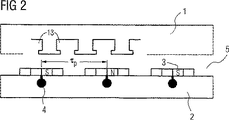
図2は、かご形誘導巻線導体4の導体棒数を利用磁極数2pNSに対応して設定してなる回転子2の実施態様を示す。
Figure 2 shows an embodiment of the
図3は、かご形誘導巻線導体4の導体棒数が利用磁極数2pNSの半分に対応する回転子2のかご形誘導巻線導体4を示す。
FIG. 3 shows the squirrel-cage
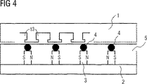
永久磁石3をギャップに配置する代りに、永久磁石3を回転子2の成層鉄心内に配置して磁束の集中を図ってもよい。図4は磁束集中装置を備えた回転子の展開図である。その際、永久磁石3は、かご形誘導巻線導体4のほぼ放射方向内側に配置する。
Instead of arranging the
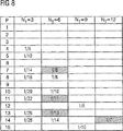
固定子1の分数スロット巻線の場合においてのみ、一緒に回転する分数調波が生じる。その場合、スロット数qは、任意の次数をzとすると、q=z/Nと表され、このスロットの数qを決める分母Nは6より大きい。即ちN>6でなければならない。この結果、図8に纏めて示したような巻線の変形例(つまり本発明に係る巻線の実施例としての、幾つかの巻線構成のバリエーション)のみが、本発明の企図するところの目的を達成できる。
Only in the case of the fractional slot winding of the
一緒に回転する分数調波の抑制の結果、大きな付加的加速モーメントが生じる故、加速駆動装置への適用が特に有効である。特に生産機械で、この同期機を良好に適用できる。 As a result of the suppression of the subharmonic rotating together, a large additional acceleration moment is produced, so application to an acceleration drive is particularly effective. This synchronous machine can be satisfactorily applied particularly to production machines.
本質的な設計基準は、回転磁界の回転方向である。2pNAの回転方向が、同期機の役割を果たすために利用される利用磁極数2pNSに対応しており、その結果、次の基準を満たさなければならない。即ち、i=1、2、・・・であるとして、
2pNS=2pNA+i×3
である。
An essential design criterion is the direction of rotation of the rotating magnetic field. The rotation direction of 2p NA corresponds to the number of magnetic poles used 2p NS used for the role of the synchronous machine, and as a result , the following standard must be satisfied. That is, assuming that i = 1, 2,...
2p NS = 2p NA + i × 3
It is.
従って、本発明に係る一実施例としては、例えば、固定子の実体的な磁極数である固定子磁極数2pSTの値は、固定子の基本磁極数2pGS 以上であり、かつ2P NS は2p GS 以上であり、また、永久磁石の実体的な磁極数2p RS は、2P NS と等しく、また、かご形誘導巻線導体によって形成される回転子の磁極数2p RA は、2p NA に等しくすることなどが可能である。 Accordingly, an embodiment of the present invention, for example, the value of the stator magnetic poles 2p ST is substantive poles of the stator is a fundamental pole number 2p GS or stator, and 2P NS is 2p GS or more, the substantial magnetic pole number 2p RS of the permanent magnet is equal to 2P NS, and the magnetic pole number 2p RA of the rotor formed by the squirrel-cage induction winding conductor is equal to 2p NA . It is possible to do .
その場合、特に磁極ピッチτPに対するコイル幅τSPの比は、
2.66≦τSP/τP
である。因みに公知の同期機では、それは1.33未満である。ここで、磁極ピッチτPは、2つの異極性磁極間のピッチ幅を意味する。
In that case, in particular, the ratio of the coil width τ SP to the magnetic pole pitch τ P is
2.66 ≦ τ SP / τ P
It is. In the known synchronous machine, it is less than 1.33. Here, the magnetic pole pitch τ P means the pitch width between two different polarity magnetic poles.
図5は、ハウジング11内に固定子1を備えた永久磁石励磁式同期電動機10を示す。固定子1は均等に分布したスロット13を持つ。ハウジング11と固定子1の間で、液状又はガス状の冷却媒体により冷却を行う冷却ジャケット12を設けている。固定子1のスロット13には、巻線装置U、V、Wを納めている。回転子2は外周部に永久磁石3を備え、該磁石3は可撓性テープ14又はスリーブで回転子2に固定する。
FIG. 5 shows a permanent magnet excitation type
永久磁石3は平坦又は曲面状に形成する。永久磁石3の放射方向内側にかご形誘導巻線導体4が位置している。調節ばねやトラバース等の適当な軸とボスを結合する結合手段16によって駆動軸15を回転子2にそれと一緒に回転するように結合している。
The
図6は図5に示す回転子2の断面図を再掲する。ただし、ここでは永久磁石3の極性N又はSを付加して示している。
FIG. 6 shows a cross-sectional view of the
図7は回転子2の端面図を示す。ここでは、かご形誘導巻線導体4の接続関係を付加して示している。
FIG. 7 shows an end view of the
1 固定子、 2 回転子、3 永久磁石、4 かご形誘導巻線導体、5 ギャップ、10 永久磁石励磁式同期電動機、11 ハウジング、12 冷却ジャケット、13 スロット、14 テープ、15 駆動軸、16 結合手段 DESCRIPTION OF
Claims (8)
前記固定子(1)の巻線装置によって発生されるギャップ磁界の基本磁極数を2p GS とし、前記固定子(1)が同期機の役割を果たすために利用される磁極数を2p NS とし、前記固定子(1)が非同期機の役割を果たすために利用される磁極数を2p NA として、
前記回転子の磁極数が、前記固定子(1)の前記基本磁極数2p GS よりも多いこと、及び
前記固定子(1)の基本磁極数2pGSと前記固定子(1)が同期機の役割を果たすために利用される磁極数2p NS との関係が、2pNS ≧4×2pGS であること、並びに
前記固定子(1)が非同期機の役割を果たすために利用される磁極数である前記磁極数2p NA と前記固定子(1)の前記基本磁極数2p GS との関係が、前記磁極数2p NS との関係も含めて、2p NS >2pNA≧2pGS であること、並びに
前記永久磁石(3)の磁極ピッチτPに対する前記固定子(1)のコイル幅τSPの比が、2.66≦τSP/τPであること
を特徴とする同期機。Comprising a stator (1) and the rotor (2), the stator (1) comprises a winding device with a fractional-slot winding of q ≦ 0.5, wherein the rotor (2) is a permanent magnet (3) and provided with a squirrel cage induction winding conductor for using subharmonic magnetic field for asynchronously (4), and
The basic magnetic pole number of the gap magnetic field generated by the winding device of the stator (1) is 2p GS, and the magnetic pole number used for the stator (1) to act as a synchronous machine is 2p NS , the number of magnetic poles to be utilized the stator (1) is to serve asynchronous machine as a 2p NA,
Number of poles of the rotor, the basic be greater than the number of magnetic poles 2p GS, and the basic magnetic poles 2 p GS and the stator (1) is a synchronous machine of the stator (1) of the stator (1) The relationship with the number of magnetic poles 2p NS used to play the role of 2p NS ≧ 4 × 2p GS , and
The stator (1) is the relationship between the fundamental pole number 2p GS of the number of magnetic poles 2p NA and the stator is a number of poles that are used to serve the asynchronous machine (1), the number of magnetic poles 2p 2p NS > 2p NA ≧ 2p GS , including the relationship with NS, and
Wherein a ratio of coil width tau SP of the relative pole pitch tau P of the permanent magnets (3) the stator (1) is a synchronous machine, which is a 2.66 ≦ τ SP / τ P.
Applications Claiming Priority (1)
| Application Number | Priority Date | Filing Date | Title |
|---|---|---|---|
| PCT/DE2003/003020 WO2005027321A1 (en) | 2003-09-11 | 2003-09-11 | Three-phase synchronous machine comprising a permanent magnet rotor and an induction cage |
Publications (3)
| Publication Number | Publication Date |
|---|---|
| JP2007507191A JP2007507191A (en) | 2007-03-22 |
| JP2007507191A5 JP2007507191A5 (en) | 2010-02-25 |
| JP4772503B2 true JP4772503B2 (en) | 2011-09-14 |
Family
ID=34305469
Family Applications (1)
| Application Number | Title | Priority Date | Filing Date |
|---|---|---|---|
| JP2005508857A Expired - Fee Related JP4772503B2 (en) | 2003-09-11 | 2003-09-11 | Three-phase synchronous machine including a permanent magnet type rotor having a squirrel-cage induction winding conductor, a traction drive device, and a production machine device |
Country Status (6)
| Country | Link |
|---|---|
| US (1) | US7564158B2 (en) |
| JP (1) | JP4772503B2 (en) |
| CN (1) | CN100547885C (en) |
| AU (1) | AU2003271527A1 (en) |
| DE (1) | DE10394335B4 (en) |
| WO (1) | WO2005027321A1 (en) |
Families Citing this family (27)
| Publication number | Priority date | Publication date | Assignee | Title |
|---|---|---|---|---|
| DE102005019112A1 (en) * | 2005-04-25 | 2006-10-26 | Siemens Ag | Combination motor consists of linear and rotation motor systems with at least one of them having hybrid reluctance motor and each having a permanent magnet-free armature with grooves in its axis and periphery |
| DE102008019644A1 (en) * | 2008-04-18 | 2009-10-22 | Siemens Aktiengesellschaft | Electric drive machine |
| US20100090549A1 (en) * | 2008-10-10 | 2010-04-15 | General Electric Company | Thermal management in a fault tolerant permanent magnet machine |
| US20100090557A1 (en) * | 2008-10-10 | 2010-04-15 | General Electric Company | Fault tolerant permanent magnet machine |
| DE102008043991A1 (en) * | 2008-11-21 | 2010-05-27 | Thielert Aircraft Engines Gmbh | Fuel pump for internal combustion engines |
| DE102010001997B4 (en) | 2010-02-16 | 2016-07-28 | Siemens Aktiengesellschaft | Linear motor with reduced power ripple |
| DE102010028872A1 (en) | 2010-05-11 | 2011-11-17 | Siemens Aktiengesellschaft | Drive device for rotary and linear movements with decoupled inertia |
| CN102013779B (en) * | 2010-12-09 | 2012-11-07 | 南昌大学 | Hybrid excitation permanent magnet motor of quintuple harmonic excitation |
| EP2508769B1 (en) | 2011-04-06 | 2013-06-19 | Siemens Aktiengesellschaft | Magnetic axial bearing device with increased iron filling |
| EP2523319B1 (en) | 2011-05-13 | 2013-12-18 | Siemens Aktiengesellschaft | Cylindrical linear motor with low cogging forces |
| DK2533402T3 (en) * | 2011-06-10 | 2022-08-01 | Siemens Gamesa Renewable Energy As | Electric machine |
| US8633627B2 (en) * | 2011-08-30 | 2014-01-21 | General Electric Company | Electric machine |
| EP2604876B1 (en) | 2011-12-12 | 2019-09-25 | Siemens Aktiengesellschaft | Magnetic radial bearing with individual core plates in tangential direction |
| EP2639934B1 (en) | 2012-03-16 | 2015-04-29 | Siemens Aktiengesellschaft | Rotor with permanent excitation, electrical machine with such a rotor and method for producing the rotor |
| EP2639936B1 (en) | 2012-03-16 | 2015-04-29 | Siemens Aktiengesellschaft | Electrical machine with permanently excited rotor and permanently excited rotor |
| EP2639935B1 (en) | 2012-03-16 | 2014-11-26 | Siemens Aktiengesellschaft | Rotor with permanent excitation, electrical machine with such a rotor and method for producing the rotor |
| EP2709238B1 (en) | 2012-09-13 | 2018-01-17 | Siemens Aktiengesellschaft | Permanently excited synchronous machine with ferrite magnets |
| EP2793363A1 (en) | 2013-04-16 | 2014-10-22 | Siemens Aktiengesellschaft | Single segment rotor with retaining rings |
| CN105122598B (en) | 2013-04-17 | 2017-09-01 | 西门子公司 | Motor with axially and tangentially flux concentration |
| EP2838180B1 (en) | 2013-08-16 | 2020-01-15 | Siemens Aktiengesellschaft | Rotor of a dynamo-electric rotational machine |
| EP2928052A1 (en) | 2014-04-01 | 2015-10-07 | Siemens Aktiengesellschaft | Electric machine with permanently excited internal stator and outer stator having windings |
| EP2999090B1 (en) | 2014-09-19 | 2017-08-30 | Siemens Aktiengesellschaft | Permanently excited rotor with a guided magnetic field |
| DE102014118356A1 (en) | 2014-12-10 | 2016-06-16 | Feaam Gmbh | Power unit and electrical machine |
| EP3035496B1 (en) | 2014-12-16 | 2017-02-01 | Siemens Aktiengesellschaft | Rotor for a permanent magnet excited electric machine |
| EP3211774A1 (en) * | 2016-02-26 | 2017-08-30 | Siemens Aktiengesellschaft | Permanently excited synchronous machine with coils in the rotor |
| EP3373421B1 (en) | 2017-03-09 | 2019-11-20 | Siemens Aktiengesellschaft | Housing unit for an electric machine |
| CN113691093B (en) * | 2021-07-30 | 2022-12-09 | 齐鲁工业大学 | Outer rotor permanent magnet induction motor and working method |
Citations (2)
| Publication number | Priority date | Publication date | Assignee | Title |
|---|---|---|---|---|
| JPS502107A (en) * | 1973-04-13 | 1975-01-10 | ||
| JP2003134773A (en) * | 2001-10-16 | 2003-05-09 | Hitachi Ltd | Self-starting synchronous motor and compressor using the same |
Family Cites Families (9)
| Publication number | Priority date | Publication date | Assignee | Title |
|---|---|---|---|---|
| DE51083C (en) | ALLGEMEINE ELEKTRICITATS-GESELLSCHAFT in Berlin N., Schlegelstr. 26 | Armature for AC motors | ||
| US1933591A (en) | 1931-01-19 | 1933-11-07 | Sangamo Electric Co | Motor |
| CH331335A (en) | 1954-04-07 | 1958-07-15 | Philips Nv | Synchronous motor with an armature with permanent magnetic poles |
| US4393344A (en) * | 1979-02-22 | 1983-07-12 | Whellams Geoffrey E | Squirrel cage induction motors |
| US4371802A (en) * | 1980-06-12 | 1983-02-01 | Morrill Wayne J | Half-pitch capacitor induction motor |
| US4453101A (en) * | 1983-09-27 | 1984-06-05 | General Electric Company | Amortisseur bar with improved interface between free conductor bars and amortisseur ring |
| US4504755A (en) | 1983-11-03 | 1985-03-12 | Kollmorgen Technologies Corporation | Rotor reluctance notch for cogging control |
| TW571487B (en) | 2001-10-16 | 2004-01-11 | Hitachi Air Conditioning Sys | Self-starting synchronous motor and compressor using the same |
| TWI224412B (en) * | 2003-07-30 | 2004-11-21 | Ming-Tsung Chu | Rotor structure of line-start permanent magnet synchronous motor |
-
2003
- 2003-09-11 JP JP2005508857A patent/JP4772503B2/en not_active Expired - Fee Related
- 2003-09-11 WO PCT/DE2003/003020 patent/WO2005027321A1/en active Application Filing
- 2003-09-11 AU AU2003271527A patent/AU2003271527A1/en not_active Abandoned
- 2003-09-11 DE DE10394335.8T patent/DE10394335B4/en not_active Expired - Fee Related
- 2003-09-11 US US10/572,008 patent/US7564158B2/en not_active Expired - Fee Related
- 2003-09-11 CN CNB038270633A patent/CN100547885C/en not_active Expired - Fee Related
Patent Citations (2)
| Publication number | Priority date | Publication date | Assignee | Title |
|---|---|---|---|---|
| JPS502107A (en) * | 1973-04-13 | 1975-01-10 | ||
| JP2003134773A (en) * | 2001-10-16 | 2003-05-09 | Hitachi Ltd | Self-starting synchronous motor and compressor using the same |
Also Published As
| Publication number | Publication date |
|---|---|
| JP2007507191A (en) | 2007-03-22 |
| WO2005027321A1 (en) | 2005-03-24 |
| AU2003271527A1 (en) | 2005-04-06 |
| US20070035193A1 (en) | 2007-02-15 |
| DE10394335D2 (en) | 2006-07-27 |
| CN100547885C (en) | 2009-10-07 |
| CN1839530A (en) | 2006-09-27 |
| US7564158B2 (en) | 2009-07-21 |
| DE10394335B4 (en) | 2014-07-31 |
Similar Documents
| Publication | Publication Date | Title |
|---|---|---|
| JP4772503B2 (en) | Three-phase synchronous machine including a permanent magnet type rotor having a squirrel-cage induction winding conductor, a traction drive device, and a production machine device | |
| US6590312B1 (en) | Rotary electric machine having a permanent magnet stator and permanent magnet rotor | |
| KR101011396B1 (en) | Motor and motor system | |
| JP4158024B2 (en) | Induction motor | |
| EP1879283B1 (en) | Motor | |
| JPH08182281A (en) | Spindle motor | |
| JP2006246571A (en) | Reluctance motor | |
| WO2002021665A2 (en) | Dc- or ac- commutator motors with concentrated windings | |
| JP6222032B2 (en) | Rotating electric machine | |
| JP2007507192A (en) | Rotating electric machine having induction rotor | |
| JP2007507191A5 (en) | ||
| JP3535485B2 (en) | Three-phase hybrid type stepping motor | |
| JP2003037969A (en) | Permanent magnet three-phase stepping motor | |
| KR20010041091A (en) | Rotating Electric Machine with Permanent Magnets and Magnetic Resistance Having an Improved Structure | |
| JP3280351B2 (en) | Brushless motor | |
| JP3444637B2 (en) | Armature of rotating electric machine | |
| JP3655205B2 (en) | Rotating electric machine and electric vehicle using the same | |
| Harris et al. | Variable reluctance permanent magnet motors for high specific output | |
| JP2003250254A (en) | Permanent magnet type brushless motor for electric power steering apparatus | |
| JP3350971B2 (en) | PM type vernier motor | |
| JPH04210758A (en) | Permanent magnet rotor | |
| JP4039074B2 (en) | Synchronous motor | |
| Qu et al. | Split-phase claw-pole induction machines with soft magnetic composite cores | |
| JP2000125493A (en) | Magnet-type motor and generator | |
| JPH05344696A (en) | Ac generator for vehicle |
Legal Events
| Date | Code | Title | Description |
|---|---|---|---|
| A131 | Notification of reasons for refusal |
Free format text: JAPANESE INTERMEDIATE CODE: A131 Effective date: 20080501 |
|
| A601 | Written request for extension of time |
Free format text: JAPANESE INTERMEDIATE CODE: A601 Effective date: 20080731 |
|
| A602 | Written permission of extension of time |
Free format text: JAPANESE INTERMEDIATE CODE: A602 Effective date: 20080807 |
|
| A601 | Written request for extension of time |
Free format text: JAPANESE INTERMEDIATE CODE: A601 Effective date: 20080901 |
|
| A602 | Written permission of extension of time |
Free format text: JAPANESE INTERMEDIATE CODE: A602 Effective date: 20080908 |
|
| A601 | Written request for extension of time |
Free format text: JAPANESE INTERMEDIATE CODE: A601 Effective date: 20080930 |
|
| A602 | Written permission of extension of time |
Free format text: JAPANESE INTERMEDIATE CODE: A602 Effective date: 20081007 |
|
| A521 | Written amendment |
Free format text: JAPANESE INTERMEDIATE CODE: A523 Effective date: 20081030 |
|
| A524 | Written submission of copy of amendment under section 19 (pct) |
Free format text: JAPANESE INTERMEDIATE CODE: A524 Effective date: 20081030 |
|
| A131 | Notification of reasons for refusal |
Free format text: JAPANESE INTERMEDIATE CODE: A131 Effective date: 20090707 |
|
| A601 | Written request for extension of time |
Free format text: JAPANESE INTERMEDIATE CODE: A601 Effective date: 20091006 |
|
| RD03 | Notification of appointment of power of attorney |
Free format text: JAPANESE INTERMEDIATE CODE: A7423 Effective date: 20091006 |
|
| A602 | Written permission of extension of time |
Free format text: JAPANESE INTERMEDIATE CODE: A602 Effective date: 20091014 |
|
| A601 | Written request for extension of time |
Free format text: JAPANESE INTERMEDIATE CODE: A601 Effective date: 20091109 |
|
| A602 | Written permission of extension of time |
Free format text: JAPANESE INTERMEDIATE CODE: A602 Effective date: 20091116 |
|
| A601 | Written request for extension of time |
Free format text: JAPANESE INTERMEDIATE CODE: A601 Effective date: 20091207 |
|
| A602 | Written permission of extension of time |
Free format text: JAPANESE INTERMEDIATE CODE: A602 Effective date: 20091214 |
|
| A521 | Written amendment |
Free format text: JAPANESE INTERMEDIATE CODE: A523 Effective date: 20100107 |
|
| A524 | Written submission of copy of amendment under section 19 (pct) |
Free format text: JAPANESE INTERMEDIATE CODE: A524 Effective date: 20100107 |
|
| A131 | Notification of reasons for refusal |
Free format text: JAPANESE INTERMEDIATE CODE: A131 Effective date: 20100914 |
|
| A601 | Written request for extension of time |
Free format text: JAPANESE INTERMEDIATE CODE: A601 Effective date: 20101213 |
|
| A602 | Written permission of extension of time |
Free format text: JAPANESE INTERMEDIATE CODE: A602 Effective date: 20101220 |
|
| A601 | Written request for extension of time |
Free format text: JAPANESE INTERMEDIATE CODE: A601 Effective date: 20110112 |
|
| A602 | Written permission of extension of time |
Free format text: JAPANESE INTERMEDIATE CODE: A602 Effective date: 20110119 |
|
| A521 | Written amendment |
Free format text: JAPANESE INTERMEDIATE CODE: A523 Effective date: 20110208 |
|
| A01 | Written decision to grant a patent or to grant a registration (utility model) |
Free format text: JAPANESE INTERMEDIATE CODE: A01 Effective date: 20110524 |
|
| A61 | First payment of annual fees (during grant procedure) |
Free format text: JAPANESE INTERMEDIATE CODE: A61 Effective date: 20110622 |
|
| FPAY | Renewal fee payment (event date is renewal date of database) |
Free format text: PAYMENT UNTIL: 20140701 Year of fee payment: 3 |
|
| R150 | Certificate of patent or registration of utility model |
Free format text: JAPANESE INTERMEDIATE CODE: R150 |
|
| LAPS | Cancellation because of no payment of annual fees |