JP4158024B2 - Induction motor - Google Patents
Induction motor Download PDFInfo
- Publication number
- JP4158024B2 JP4158024B2 JP2003041238A JP2003041238A JP4158024B2 JP 4158024 B2 JP4158024 B2 JP 4158024B2 JP 2003041238 A JP2003041238 A JP 2003041238A JP 2003041238 A JP2003041238 A JP 2003041238A JP 4158024 B2 JP4158024 B2 JP 4158024B2
- Authority
- JP
- Japan
- Prior art keywords
- stator
- peripheral side
- winding
- side stator
- rotor
- Prior art date
- Legal status (The legal status is an assumption and is not a legal conclusion. Google has not performed a legal analysis and makes no representation as to the accuracy of the status listed.)
- Expired - Fee Related
Links
Images


Classifications
-
- H—ELECTRICITY
- H02—GENERATION; CONVERSION OR DISTRIBUTION OF ELECTRIC POWER
- H02K—DYNAMO-ELECTRIC MACHINES
- H02K17/00—Asynchronous induction motors; Asynchronous induction generators
- H02K17/02—Asynchronous induction motors
- H02K17/16—Asynchronous induction motors having rotors with internally short-circuited windings, e.g. cage rotors
-
- H—ELECTRICITY
- H02—GENERATION; CONVERSION OR DISTRIBUTION OF ELECTRIC POWER
- H02K—DYNAMO-ELECTRIC MACHINES
- H02K16/00—Machines with more than one rotor or stator
- H02K16/04—Machines with one rotor and two stators
-
- H—ELECTRICITY
- H02—GENERATION; CONVERSION OR DISTRIBUTION OF ELECTRIC POWER
- H02K—DYNAMO-ELECTRIC MACHINES
- H02K17/00—Asynchronous induction motors; Asynchronous induction generators
- H02K17/02—Asynchronous induction motors
- H02K17/04—Asynchronous induction motors for single phase current
- H02K17/08—Motors with auxiliary phase obtained by externally fed auxiliary windings, e.g. capacitor motors
Landscapes
- Engineering & Computer Science (AREA)
- Power Engineering (AREA)
- Iron Core Of Rotating Electric Machines (AREA)
- Induction Machinery (AREA)
Description
【0001】
【発明の属する技術分野】
本発明は、例えばエアコンのファンモータなどとして利用されるラジアルエアギャップ型の誘導電動機に関し、さらに詳しく言えば、2つの固定子(ステータ)を有し、それらの間に回転子(ロータ)を配置して2層のラジアルエアギャップを備える誘導電動機に関するものである。
【0002】
【従来の技術】
誘導電動機の多くは、回転磁界を発生する1つの固定子(ステータ)の内側に1つの回転子(ロータ)を配置したインナーロータ型を採用している。ステータには、回転磁界を発生するための巻線が施されているが、ロータには、誘導電流を発生させるためのかご型巻線が施されている。
【0003】
この誘導電動機によれば、ロータをステータによる回転磁界の中に置くと、ロータのかご型巻線に誘導電流が流れ、その回転磁界と誘導電流の両者の相互作用によりかご型巻線に回転力(トルク)が働き、ロータが回転する。このような誘導電動機は簡便性、経済性の観点から家電製品や産業機械に多く利用されている。
【0004】
【発明が解決しようとする課題】
しかしながら、従来の誘導電動機にあっては、小型になるほど出力の割に損失が大きくなり、効率が低下する傾向にあり、しかも、その極数が多くなるほど、その効率低下の傾向が強くなる。
【0005】
効率,損失,出力および入力の間には、次式のような関係がある。
効率=出力/入力=出力/出力+損失……(1)
したがって、効率を上げるためには、損失を低減すればよいことが分かる。
【0006】
誘導電動機において、損失には次のようなものがある。
▲1▼一次銅損(ステータ巻線抵抗損)
▲2▼二次銅損(ロータ巻線抵抗損)
▲3▼鉄損(ヒステリシス損)
▲4▼鉄損(うず電流損)
▲5▼機械損(軸受損,風損など)
▲6▼漂遊負荷損
【0007】
これらの中で大きい比率を占めるのは、▲1▼の一次銅損と▲2▼の二次銅損である。従来の誘導電動機で、これらの銅損を減らそうとすると、ステータコアを大きくし溝面積を増やして線径の太い巻線を巻き込んで抵抗損を減らしたり、コータコアの外径を大きくして小さな誘導電流でも、同じトルクを出せるようにするなどの方法を採らなければならない。しかしながら、これらの方法では、大幅な材料費の上昇を招くことになるため、好ましくない。
【0008】
一般に、モータの出力方程式は次式(2)で表される。
出力=K1・D2・L・Bm・Ac・n……(2)
ここで、K1は定数,Dはラジアルエアギャップの直径,Lはコア長さ,Bmはエアギャップの平均磁束密度,Acはアンペア導体数,nは回転速度である。
【0009】
誘導電動機の場合、エアギャップの平均磁束密度Bmはアンペア導体数Acにほぼ比例するので、上記の式(2)は次式(3)のように表すことができる。
出力=K2・D2・L・Bm2・n……(3)
なお、K2は定数である。
【0010】
次に、損失とエアギャップの平均磁束密度Bmとの関係を考えて見る。電流Iと最大磁束密度Bとはほぼ比例する。アンペア導体数Acは電流Iにほぼ比例し、エアギャップの平均磁束密度Bmは最大磁束密度Bにほぼ比例するため、上記▲1▼の一次銅損(電流I2・巻線抵抗)は、Bm2にほぼ比例すると見てよい。また、上記▲2▼の二次銅損は、(ロータ巻線に流れる二次電流)2・二次抵抗であり、その二次電流はBmにほぼ比例するため、上記▲2▼の二次銅損は、Bm2にほぼ比例するということができる。
【0011】
上記▲3▼の鉄損(ヒステリシス損)および上記▲4▼鉄損(うず電流損)はB2、すなわちBm2にほぼ比例することは周知のとおりである。残りの損失である上記▲5▼の機械損(軸受損,風損など)と上記▲6▼の漂遊負荷損は、全損失に占める割合は小さいとみなせるので、全損失はBm2にほぼ比例するということができる。
【0012】
効率を大幅に向上させるには、損失を可能なかぎり減らす必要がある。損失とエアギャップの平均磁束密度Bmの二乗はほぼ比例するため、損失を大幅に減らすにはBm2を大幅に減らせばよいことになる。ところが、Bm2を減らすと出力もそれに比例して減ってしまうことになるため、出力を補償する手段を講ずる必要が出でくる。
【0013】
そのための方法として、(ラジアルエアギャップの直径D)の二乗×コア長さLをBm2が少なくなった分だけ増やしてやることにより、(Bm2)×(D2・L)が不変となるため、出力を一定に保つことができる。しかしながら、従来の誘導電動機で(D2・L)を大きくしようとすると、コアサイズ(体格)が大きくなるため、不経済である。
【0014】
したがって、本発明の課題は、小出力においても、そのコアサイズ(体格)を大きくさせることなく、誘導電動機の効率を大幅に向上させることにある。
【0015】
【課題を解決するための手段】
上記課題を解決するため、本発明は、ラジアルエアギャップを備えている誘導電動機において、最外径部の固定子(外周側ステータ)と最内径部の固定子(内周側ステータ)との間に、回転子(ロータ)を配置して2層のエアギャップを有する構造とし、上記外周側ステータおよび上記内周側ステータには、上記ロータに対して回転磁界を発生する巻線を施し、上記ロータには、かご型巻線を施してなることを特徴としている。
【0016】
このように、ラジアルエアギャップを2層とし、その各々のラジアルエアギャップの直径をできるだけ大きくすることにより、大幅に(D2・L)を大きくすることができるため、Bm2も大幅に低減でき、これに伴って損失を大幅に減らすことが可能となる。したがって、コアサイズ(体格)を大きくすることなく、効率を向上させることができる。ラジアルエアギャップを2層とした場合の出力方程式は次式(4)によって表される。
出力=K2・(Do2+Di2)・L・Bm2・n……(4)
式中、Doは外側のラジアルエアギャップの直径で、Diは内側のラジアルエアギャップの直径である。
【0017】
上記外周側ステータと内周側ステータのスロットは同じ数もしくは異る数であり、上記ロータのスロットは素数×2もしくは素数×4の数であるとよい。これにより、かご形巻線のロータが誘導電動機にとって適切なものになる。
【0018】
上記外周側ステータの内周側に施す巻線のピッチと内周側ステータの外周側に施す巻線のピッチを同じピッチもしくは異なるピッチにするとよい。これにより、使用目的などに適した誘導電動機が実現される。
【0019】
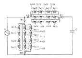
本発明によれば、上記外周側ステータと内周側ステータは、ともに同数もしくは異なる数のスロットを有して相対的に空間的位相角を電気角でπ/2ずらし、外周側ステータの内周側に設けた歯には集中巻で主巻線および補助巻線を施し、内周側ステータの外周側に設けた溝には分布巻または全節巻で主巻線と補助巻線を施して、各ステータに回転磁界を発生させ、該回転磁界によりロータのかご型巻線に誘導電流が流れるコンデンサ誘導電動機とすることができる。
【0020】
図4ないし図6を参照して、本発明によれば、上記外周側ステータの12スロットを構成する歯には、それぞれ主巻線および補助巻線を交互に施すとともに、その主巻線および補助巻線がそれぞれ隣接同士で逆向きの磁束を発生するように直列に接続する。一方、上記内周側ステータの12スロットを構成する溝には、2スロットピッチの主巻線および補助巻線をそれぞれ3個づつ1スロット置きに順に施し、それら主巻線と補助巻線とが1スロットずらして施されるようにするとともに、それら主巻線および補助巻線がそれぞれ同じ方向の磁束を発生するように直列に接続する。そして、外周側ステータの主巻線と内周側ステータの主巻線とを直列に接続してコンデンサ誘導電動機の主巻線にするとともに、外周側ステータの補助巻線と内周側ステータの補助巻線とを直列に接続してコンデンサ誘導電動機の補助巻線とすることにより、6極のコンデンサ誘導電動機が得られる。
【0021】
上記外周側ステータと内周側ステータは、同数のスロットを有して同外周側ステータの内周側に設けた歯と内周側ステータの外周側に設けた歯とを対向させ、その外周側ステータおよび内周側ステータの歯には、それぞれ集中巻で主巻線および補助巻線を施して各ステータに回転磁界を発生させ、該回転磁界により上記ロータのかご型巻線に誘導電流が流れるようにしたコンデンサ誘導電動機を構成するとよい。
【0022】
図9ないし図11を参照して、本発明によれば、上記外周側ステータの12スロットを構成する歯にはそれぞれ6個の主巻線および補助巻線を交互に施すとともに、上記内周側ステータの12スロットを構成する歯には外周側ステータと同様に主巻線および補助巻線をそれぞれ6個を交互に施す。外周側ステータの主巻線と内周側ステータの主巻線とが同じ向きの磁束発生状態にし、かつ、隣接する主巻線によって発生する磁束を逆向きになるように直列に接続する。外周側ステータの補助巻線と内周側ステータの補助巻線とが同じ向きの磁束発生状態にし、かつ、その隣接する補助巻線によって発生する磁束を逆向きになるように直列に接続する。外周側ステータおよび内周側ステータの主巻線を直列に接続したものをコンデンサ誘導電動機の主巻線にするとともに、外周側ステータおよび内周側ステータの補助巻線を直列に接続したものをコンデンサ誘導電動機の補助巻線にすることにより、6極のコンデンサ誘導電動機が得られる。
【0023】
上記外周側ステータと内周側ステータは同数のスロットを有して同外周側ステータの内周側に設けた歯と内周側ステータの外周側に設けた歯とを対向させ、外周側ステータおよび内周側ステータの歯にはそれぞれ集中巻で三相巻線を施して回転磁界を発生させ、該回転磁界により上記ロータのかご型巻線に誘導電流が流れるようにした三相誘導電動機を構成するとよい。
【0024】
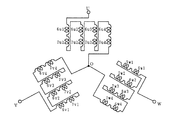
図12ないし図14を参照して、本発明によれば、上記外周側ステータの各歯には三相の巻線をそれぞれ順次施し、上記内周側ステータの各歯には外周側ステータと同様の三相の巻線を順次施す。各相の巻線について、それぞれ外周側ステータの巻線と内周側ステータの巻線とを交互に直列に接続するとともに、それぞれ外周側ステータの巻線と相対する内周側ステータの巻線とを同じ向きの磁束発生状態にし、かつ、それぞれ隣接する巻線によって逆向きの磁束を発生するように直列に接続する。これら直列に接続した各相の巻線をY結線にすることにより、三相誘導電動機が得られる。
【0025】
上記外周側ステータおよび内周側ステータはそのコアに絶縁を施した後、コイルを手入れもしくはインサータでスロットに挿入し、もしくは歯に直に巻線を施すか、あるいはステータのヨーク部にトロイダル巻線を施すとよい。このようにして、誘導電動機の特性などに合わせた巻線を用いることにより、最適な誘導電動機が得られる。
【0026】
上記ロータは少なくともティースおよびスロットを有するコアと、同スロットを介して施したかご型巻線とから構成し、コアはプレス金型内で電磁鋼板をロータシャフトの軸方向に自動積層し、スロットには導電性金属によりかご型巻線を形成するとよい。これによれば、従来の製造装置を用いて誘導電動機を製造することができ、コスト上昇を抑えることができる。
【0027】
上記巻線を施した外周側ステータおよび内周側ステータは熱硬化性樹脂によって一体成形し、これをブラケットの内側に固着することが好ましい。また、上記外周側ステータはブラケットの内径嵌合部に固着するとともに、内周側ステータは保持部によってブラケットの内側面に固着し、もしくはシャフトの軸受けハウジング部に固着することが好ましい。これによれば、ステータが確実にブラケットに固定されることから、誘導電動機の信頼性が向上する。
【0028】
上記ロータコアのスロットは、外周側端もしくは内周側端をオープン形状とし、あるいはその外周側および内周側の両端をオープン形状もしくはクローズド形状としており、その一方もしくは双方をオープン形状とする場合にはコア積層シートの一部をクローズスロットのものにすることが好ましい。これにより、ロータには連続的でない、独立した歯が形成されることから、磁束の有効利用が図れ、つまりモータの高効率化が図られる。
【0029】
上記ロータはアルミダイカスによってかご型巻線をスロットを介して形成し、エンドリングに連結して少なくとも一方のエンドリング側に継ぎ手を設けてロータシャフトに固着することが好ましい。これにより、かご型巻線の製造が容易に行え、コストダウンを図ることができる。
【0030】
また、上記ロータのコアはすべてオープンスロットとし、すべてのティースはリング状のアームで連結されている構造とすることにより、磁束がティースに集中して磁束密度が高められるため、効率をより高めることができる。
【0031】
【発明の実施の形態】
次に、図1ないし図17を参照して、本発明の実施形態について説明する。本発明の誘導電動機は、従来のロータヨークに相当していた部分を最内径部のステータに利用し、最外径部の外周側ステータと最内径部の内周側ステータとの間に、ロータを配置して2層のラジアルエアギャップを形成する構造とし、ステータ巻線抵抗を抑えながら磁気抵抗を抑えるように2つのステータに巻線を施し、(Do2+Di2)・Lを大きくし、Bm2を小さくすることにより、損失を大幅に低減して高効率化を実現している。
【0032】
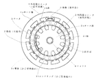
図1ないし図3に示すように、この誘導電動機は、最外径部の外周側ステータ1と、この外周側ステータ1の内側に配置した最内径部の内周側ステータ2と、それら外周側ステータ1と内周側ステータ2との間に配置されるロータ3と、このロータ3を中心のロータシャフト4に固定するための断面コ字形状の継手部5とを備えている。すなわち、外周側ステータ1の内周とロータ3の外周との間およびロータ3の内周と内周側ステータ2の外周との間には、それぞれエアギャップが形成される。
【0033】
外周側ステータ1は、所定肉厚とした円筒形のヨーク部1aの内周側に、ロータシャフト4の方向に延びた歯部1bを複数個(例えば12個)円周方向に等間隔に形成するとともに、これらの歯1bに集中巻の巻線6を施してなる。
【0034】
内周側ステータ2は、円柱形のヨーク部2aの外周側に、放射状に延びた歯2bを複数個(例えば12個)円周方向に等間隔に形成するとともに、これらの歯2bに分布巻の巻線7を複数個施してなる。なお、外周側ステータ1および内周側ステータ2のスロット数は12個に限られるものでなく、他の数のスロット構造としてもよい。
【0035】
ロータ3は所定肉厚の円筒形であり、ロータシャフト4の軸方向と平行ないしは適当なスキュー角を設けてなる導体(導電性金属)3aをそのロータ3の円筒部分に等間隔に複数個(例えば20個)配置し、それら導体3aの両端をそれぞれエンドリング(短絡環)3bで連結したかご型巻線を備えている。
【0036】
すなわち、ロータ3はヨークがなく、ティースおよびスロットからなり、各スロットは例えば楕円形,円形,台形などであり、導体3aを収納する。導体3aを収納するスロットの数は素数×2(10,14,22,26,34,38,46など)、もしくは素数×4(20,28,44など)にすることが好ましい。
【0037】
なお、外周側ステータ1、内周側ステータ2およびロータ3の径はモータ仕様および特性などによって決定されてよい。また、外周側ステータ1および内周側ステータ2のスロット数、ステータ巻線の数、巻線ピッチおよびロータ3のスロット数についても、モータ仕様および特性などを勘案して適宜決定されてよい。
【0038】
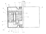
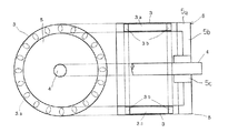
断面コ字形状の継手部5は、ロータ3の端部に接続する同形の円筒部5aと、この円筒部5aをロータシャフト4に固定する円盤部5bとからなり、円盤部5bの中心部にはボス5cを設け、ボス5cの中央には、円筒部5aのロータコアと同心度および同軸度のとれた穴を設け、その穴を焼きばめするなどすることによって、円盤部5bをロータシャフト4に固定するとよい。
【0039】
また、上記巻線6を施した外周側ステータ1および巻線7を施した内周側ステータ2は熱硬化性樹脂8によって一体化し、これをモータのブラケット(外被)9の内側に固着し、上記ロータ3、ロータシャフト4は軸受部10を介してブラケット9にて保持する。
【0040】
ここで、上記外周側ステータ1、内周側ステータ2およびロータ3の製造について説明する。電磁鋼板をプレス金型内で打ち抜いてロータシャフト4の軸方向に自動積層するが、ロータ3のコアについては電磁鋼板を中空円盤状に打ち抜くとともに、外周側および内周側をクローズとしたクローズドスロットとして打ち抜いてティースおよびスロットを形成して積層する。この場合、ロータ3のスロットがクローズドであることから、そのロータ3のティースは連続したものとなる。
【0041】
外周側ステータ1および内周側ステータ2に施す巻線については、それらのコアに絶縁を施した後に、手入れまたはインサータによって巻線をスロットに挿入して得るか、その外周側ステータ1および内周側ステータ2の歯1b,2bにじかに巻線を施すかもしくはそれらのヨークにトロイダル巻線を施して得る。
【0042】
ロータ3のかご型巻線については、アルミダイカストによって導体3aをクローズドスロット内に設けるとともに、その一端にエンドリング3bを連結して継手部5によってロータシャフト4に固着し、またその他端にもエンドリング3bを連結して得る。
【0043】
ここで、本発明例と従来例とについて、電磁界解析・シミュレーションを行った結果を次表に示す。
【表1】

以上具体例で説明したように、本発明によれば、次の技術的手段(1)〜(10)を講ずることによって、従来の技術よりも効率の高い誘導電動機を得ることができる。
(1)ロータを中央に挟んで、その外周側と内周側とにステータを2個配置し、エアギャップを2層とする。
(2)エアギャップの直径は従来のモータより大きくし、(Do2+Di2)の値をできるだけ大きくとる(上記の例では約3.07)。
(3)磁束密度Bmは、ほぼ1/√(Do2+Di2)に小さくする(上記の例では0.57)。
(4)ステータのティース幅やヨーク幅は、磁束密度Bmに比例して狭くし、その分、溝面積は広くして巻線の線径を太くできるようにし、巻線抵抗を小さくする。
(5)ステータ巻線の起磁力(AT)は、外周側ステータ巻線と内周側ステータ巻線との合成ATの空間高調波が極力少なくなるような巻線を施す。
(6)そのため、必ずしも外周側ステータコアと内周側ステータコアとのティースは等しくなくてもよい。
(7)ステータ巻線方式には、集中巻,分布巻,トロイダル巻などの巻線方式を採用する。
(8)ロータコアは、外周側および内周側ともオープンスロットが好ましい。ただし、ほぼ同心円上にすべてのティースをつなぐ環状のアームないしは連結環を設けてもよい。また、部分的にクローズドスロットのロータコアシートですべてのティースを連結して積層してもよい。
(9)ロータは、アルミニウムなどの金属でダイカストし、かご型巻線を形成する。その際、片側のエンドリングには、ロータをシャフトに固定するための円盤状のボスを一体的にダイカストする。
(10)巻線を施した内周側ステータと外周側ステータとをブラケットに固定する。その場合、内周側ステータは片持構造とする。あるいは、巻線を施した内周側ステータと外周側ステータとを片持構造にて樹脂で一体成形する。
【0045】
次に、本発明の誘導電動機の第1の実施例を図4ないし図6を参照して説明する。なお、図1と同一部分には同一符号を付して重複説明を省略し、また図4および図5中、丸内の数字はステータの各スロット番号を示している。
【0046】
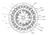
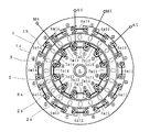
この誘導電動機は、6極コンデンサ誘導電動機であり、外周側ステータ1および内周側ステータ2は、それぞれ極数に応じた数(例えば12スロット)の歯1b,2bを有している。その歯1bと歯2bとは交互に中間の位置関係であり、つまりその位置関係は空間的位相角をπ/2ずらしてなる。
【0047】
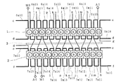
外周側ステータ1は、各歯1bに集中巻で主巻線6m1,…,6m6と補助巻線6a1,…,6a6とを交互に施し、内周側ステータ2には全節巻で主巻線7m1,7m2,7m3および補助巻線7a1,7a2,7a3を施している。
【0048】
内周側ステータ2は、2スロットに渡る主巻線7m1,7m2,7m3および補助巻線7a1,7a2,7a3を、それぞれ1スロット置き順次施してなり、かつ主巻線7m1,7m2,7m3と補助巻線7a1,7a2,7a3とは1スロットずれた位置関係としている。
【0049】
主巻線については、外周側ステータ1の主巻線6m1,…,6m6を順に直列に接続するとともに、内周側ステータ2の主巻線7m1,7m2,7m3を順に直列に接続し、かつそれら外周側と内周側の主巻線を直列に接続する。また、補助巻線については、外周側ステータ1の補助巻線6a1,…,6a6および内周側ステータ2の補助巻線7a1,7a2,7a3を主巻線と同様に接続する。
【0050】
この場合、外周側ステータ1の主巻線6m1,6m3,6m5および補助巻線6a1,6a3,6a5と、主巻線6m2,6m4,6m6および補助巻線6a2,6a4,6a6とが歯に対して逆方向の磁束を発生するように接続する。内周側ステータ2の主巻線7m1,7m2,7m3および補助巻線7a1,7a2,7a3については、歯に対して同じ方向の磁束を発生するように接続する。
【0051】
具体的例には、ロータ3に対して外周側ステータ1の主巻線6m1,6m3,6m5によって同じ極が(例えばS極)発生し、主巻線6m2,6m4,6m6によって逆のN極が発生し、内周側ステータ2の主巻線7m1,7m2,7m3によってN極が発生する。
【0052】
また、外周側ステータ1の補助巻線6a1,6a3,6a5によって同じ極(例えばN極)が発生し、内周側ステータ2の補助巻線6a2,6a4,6a6によって逆のS極が発生し、補助巻線7a1,7a2,7a3によってS極が発生する。
【0053】
そして、上記補助巻線に対して直列にコンデンサC(図6参照)を接続するとともに、この直列回路に対して並列に主巻線を接続して、この並列回路に交流電源Eを印加する。すると、外周側ステータ1および内周側ステータ2には6極の磁極が発生し、かつ、その磁界が回転する。この回転磁界中にあるロータ3の導体3aには誘導電流が流れ、この電流と回転磁界との相互作用により回転力が導体3aに働いてロータ3が回転する。
【0054】
このような2層のラジアルエアギャップ型の6極コンデンサ誘導電動機にあっては、上述したように、2層のエアギャップによる効果が得られる。すなわち、D2Lを(Do2+Di2)Lと大きくし、Bm2を小さくして損失を減らすことにより、高効率化が図られる。
【0055】
なお、上述したロータ3にあっては、かご型巻線の導体3aを納めるためにクローズドスロットが形成されているが、スロットの形状を図7あるいは図8に示すオープンスロットにすることもできる。
【0056】
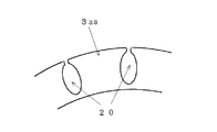
図7に示すスロットは、ロータ3の外周側を切り取ったオープンスロット20としてなる。これにより、ロータ3には独立した歯3aaが形成され、つまりステータからの磁束がその歯に集中し(磁束密度が高くなり)、磁束を効果的に利用して効率向上を図ることができる。なお、上記オープンスロット20としては、ロータ3の内周側を切り取ったものであっても、上述した効果が得られる。
【0057】
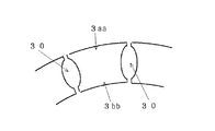
また、図8に示すように、そのスロットの形状としてはロータ3の外周側および内周側の両端部を切り取ったオープンスロット30とするとよい。これにより、ロータ3には外周側および内周側にそれぞれ独立した歯3aa,3bbが形成され、一方のみオープンとしたスロットよりも磁束が効果的に利用されることになる。
【0058】
この場合、電磁鋼板を打ち抜いてロータシャフト4の軸方向に積層してロータ3を得る際に、そのオープンスロット20やオープンスロット30を形成するが、このオープンスロット30を形成したものを用いる場合、その積層する一部をクローズスロットとしたもの(第1の実施例のもの)を用いる。
【0059】
図9ないし図11は、本発明の第2の実施例を示す概略的平面図、概略的展開図および概略的結線回路図である。なお、図1と同一部分には同一符号を付して重複説明を省略し、また図9および図10中、丸内の数字は前実施例と同様のスロット番号を示している。
【0060】
この誘導電動機は、6極コンデンサ誘導電動機あり、その外周側ステータ1および内周側ステータ2は前実施例と同じ数の歯1b,2bを有しているが、その歯1aと歯2bとが相対向する位置関係となっている。
【0061】
外周側ステータ1には、第1の実施例と同様に各歯1bに集中巻で主巻線6m10,…,6m15と補助巻線6a10,…,6a15とを交互に施し、内周側ステータ2には外周側ステータ1の巻線と同様に集中巻で主巻線7m10,…7m15,と補助巻線7a10,…,7a15とを交互に施している。
【0062】
内周側ステータ2の主巻線7m10,7m12,7m14および補助巻線7a10,7a12,7a14については、外周側ステータ1の主巻線および補助巻線と同様に集中巻で交互に施してなる。
【0063】
外周側ステータ1の主巻線と内周側ステータ2の主巻線とは交互に接続し、つまり主巻線6m10,7m10,6m11,7m11,…,6m15,7m15を順に直列に接続する。また、補助巻線については、主巻線と同様に接続し、つまり補助巻線6a10,7a10,6a11,7a11,…,6a15,7a15を順に直列に接続する。
【0064】
この場合、外周側ステータ1の主巻線6m10,6m12,6m14および補助巻線6a10,6a12,6a14は、歯に対して同じ方向の磁束を発生し、また、同様に主巻線6m11,6m13,6m15および補助巻線6a11,6a13,6a15についても、歯に対して同じ方向の磁束を発生するように接続する。しかも、上記偶数の添え字の巻線と奇数の添え字の巻線とは逆方向の磁束を発生するように接続する。
【0065】
上記外周側ステータ1と同様に、内周側ステータ2の主巻線7m10,7m12,7m14および補助巻線7a10,7a12,7a14は、歯に対して同じ方向の磁束を発生し、また、主巻線7m11,7m13,7m15および補助巻線7a11,7a13,7a15は歯に対して同じ方向の磁束を発生するように接続する。
【0066】
しかも、主巻線7m10,7m12,7m14および補助巻線7a10,7a12,7a14と主巻線7m11,7m13,7m15および補助巻線7a11,7a13,7a15とが逆方向に磁束を発生するように接続する。
【0067】
具体的には、ロータ3に対して外周側ステータ1の主巻線6m10,6m12,6m14によって同じ極が(例えばS極)発生し、主巻線6m11,6m13,6m13によって逆のN極が発生し、内周側ステータ2の主巻線7m10,7m12,7m14によってN極が発生し、主巻線6m11,6m13,6m13によってS極が発生する。
【0068】
すなわち、外周側ステータ1の歯1bにおける磁束の向きが中心方向であれば、その歯1bと対向する内周側ステータ2の対向する歯2bにおける磁束も中心方向である。
【0069】
また、補助巻線については、主巻線と同様であり、外周側ステータ1の補助巻線6a10,6a12,6a14によって同じ極(例えばN極)が発生し、補助巻線6a11,6a13,6a115内によって逆のS極が発生し、内周側ステータ2の補助巻線6a10,6a12,6a14によってS極が発生し、補助巻線7a11,7a13,7a15によってN極が発生する。
【0070】
そして、第1の実施例と同様に、補助巻線に対して直列にコンデンサCを接続するとともに、この直列回路に対して並列に主巻線を接続し、この並列回路に交流電源Eを印加する。すると、外周側ステータ1および内周側ステータ2とによって6極の磁極が発生し、かつ、その磁界が回転する。
【0071】
この回転磁界中にあるロータ3の導体3aには誘導電流が流れ、この電流と回転磁界との相互作用により導体3aに回転力が働いてロータ3が回転する。したがって、本発明にあっては、外周側ステータ1および内周側ステータ2の主巻線および補助巻線が集中巻線であるが、第1の実施例の誘導電動機と同様の効果が得られる。
【0072】
図12ないし図14は、本発明の第3の実施例を示す概略的平面図、概略的展開図および概略的結線回路図である。なお、図12および図13中、丸内の数字は前実施例と同様のスロット番号を示し、また図1と同一部分には同一符号を付して重複説明を省略する。
【0073】
この誘導電動機は、三相の4極誘導電動機であり、その外周側ステータ1および内周側ステータ2は前実施例と同じ数の歯1b,2bを有し、その歯1bと歯2bを相対向させた位置関係としてなる。
【0074】
外周側ステータ1および内周側ステータ2には、各歯1b,2bに集中巻でU相の巻線6u1ないし6u4,7u1ないし7u4,V相の巻線6v1ないし6v4,7v1ないし7v4,W相の巻線6w1ないし6w4,7w1ないし7w4をそれぞれ3スロット置きに施してなる。また、外周側ステータ1および内周側ステータ2の巻線について、各相の巻線はそれぞれ相対して施している。
【0075】
外周側ステータ1には、巻線6u1,6w4,6v1,6u2,6w1,…,6w1,7v4を順に施し、内周側ステータ2には外周側ステータ1の巻線と同様に巻線を順に施す。U相については、巻線6u1,7u1,6u2,…,6u4,7u4を順に直列に接続し、V相については、U相巻線から2スロット置いた巻線6v1,7v1,6v2,…,6v4,7v4を順に直列に接続し、W相については、U相巻線から4スロット置いた巻線6w1,7w1,6w2,…,6w4,7w4を順に直列に接続する。
【0076】
この場合、外周側ステータ1については、巻線6u1,6u3、巻線6v1,6v3および巻線6w1,6w3が、それぞれ歯に対して同じ方向の磁束を発生し、巻線6u2,6u4、巻線6v2,6v4および巻線6w2,6w4が、それぞれ歯に対して同じ方向の磁束を発生するように接続する。
【0077】
また、内周側ステータ2の巻線については、巻線7u2,7u4、巻線7v2,7v4および巻線7w2,7w4が、それぞれ歯に対して同じ方向の磁束を発生し、巻線7u1,7u3、巻線7v1,7v3および巻線7w1,7w3が、それぞれ歯に対して同じ方向の磁束を発生するように接続する。
【0078】
そして、U相、V相およびW相巻線はY結線し、つまり巻線7u4,7v4,7w4の一端を接続し、これに三相交流の電流を流すか、120゜通電型三相インバータ電源により以下のように二相通電を行う。
【0079】
具体的には、例えば図14に示すように、U相,V相に通電を行うと、ロータ3に対して外周側ステータ1のU相巻線6u1,6u3によって同じ極(例えばS極)が発生し、U相巻線6u2,6u4によってN極が発生し、V相巻線6v1,6v3によってN極が発生し、V相巻線6v2,6v4によってS極が発生する。
【0080】
また、内周側ステータ2のU相巻線においては、その外周側ステータ1のU巻線と同じ方向の磁束が発生し、つまりロータ3に対してはU相巻線7u1,7u3によってN極が発生し、U相巻線7u2,7u4によってS極が発生する。
V相巻線においてはV相巻線7v1,7v3によってS極が発生し、V相巻線7v2,7v4によってN極が発生する。
【0081】
上記三相のうち二相に通電するように通電を切り替えることにより、外周側ステータ1および内周側ステータ2には4極の磁極が発生し、かつ、その磁界が回転する。この回転磁界中にあるロータ3の導体3aには誘導電流が流れ、この電流と回転磁界との相互作用により、導体3aに回転力が働いてロータ3が回転する。したがって、これによっても上記実施例の誘導電動機と同様の効果が得られる。
【0082】
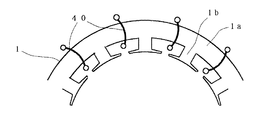
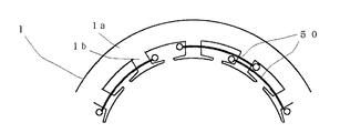
上述した実施例においては、最外径部の外周側ステータ1の巻線を集中巻としているが、図15に示すように、トロイダル巻線40をヨーク部1aにスロットを介して施し、あるいは図16に示すように、第1の実施例の内周側ステータ2の巻線のように全節巻で巻線50を所定に施すようにしてもよい。
【0083】
また、外周側ステータ1および内周側ステータ2のスロット数を同じとしているが、異なるスロット数とし、また、外周側ステータ1と内周側ステータ2のスロット数を異ならしてもよい。さらに、第2および第3の実施例では最外径部の巻線ピッチと最内径部の巻線ピッチが同じであるが、第1の実施例と同様に異なるピッチとしてもよい。
【0084】
また、2つのステータを熱硬化性樹脂8によって一体成形しているが(図2参照)、図17に示すように、内周側ステータ2を保持部60によってブラケット9の内側面に固着するか、あるいは軸受ハウジング部に固着するようにしてもよい。なお、図17中、図2と同一部分には同一符号を付して重複説明を省略する。この場合、外周側ステータ1については、ブラケット9の外径部の内径嵌合部固着する。なお、上記第2および第3の実施例には、第1の実施例と同様に、ロータ3のスロット形状などを変え、またその製造方法を適用することができる。
【0085】
【発明の効果】
以上説明したように、本発明によれば、最外径部のステータと最内径部のステータとの間にロータを配置して2層のエアギャップを有する構造とし、外周側ステータおよび内周側ステータにロータに対して回転磁界を発生する巻線を施すとともに、ロータにはかご型形巻線を施すという構成を採用したことにより、従来のインナーロータ型の誘導電動機(1層エアギャップ型モータ)と比較して、例えば同一トルク(同一出力)とする場合の消費電力が少なくてすむ。
【0086】
このことは、従来の1層エアギャップ型誘導電動機と同一の電力を消費したとすると、同じコアサイズでありながら、従来より大きいトルクが得られ、換言すれば同一トルクを得るためには少ない電力ですみ、高効率が図れることを意味している。また、ステータのトータルのスロット面積が大きくとれるため、巻線の線径を太くでき、ステータ巻線抵抗が小さくなるので一次銅損が減り、より一層の高効率化を図ることができる。
【図面の簡単な説明】
【図1】本発明による誘導電動機の実施形態を示す概略的平面図。
【図2】図1に示す誘導電動機の概略的側断面図。
【図3】図1に示す誘導電動機のロータを説明するための概略的平面図および側断面図。
【図4】本発明の第1実施例を示す誘導電動機の概略的平面図。
【図5】上記第1実施例の誘導電動機のステータ巻線を説明する概略的展開図。
【図6】上記第1実施例の誘導電動機のステータ巻線の結線を説明する概略的回路図。
【図7】本発明の誘導電動機のロータスロットの変形例を説明する概略的平面図。
【図8】本発明の誘導電動機のロータスロットの他の変形例を説明する概略的平面図。
【図9】本発明の第2実施例を示す誘導電動機の概略的平面図。
【図10】上記第2実施例の誘導電動機のステータ巻線を説明する概略的展開図。
【図11】上記第2実施例の誘導電動機のステータ巻線の結線を説明する概略的回路図。
【図12】本発明の第3実施例を示す誘導電動機の概略的平面図。
【図13】上記第3実施例の誘導電動機のステータ巻線を説明する概略的展開図。
【図14】上記第3実施例の誘導電動機のステータ巻線の結線を説明する概略的回路図。
【図15】本発明の誘導電動機のステータ巻線変形例を説明する概略的平面図。
【図16】本発明の誘導電動機のステータ巻線の他の変形例を説明する概略的平面図。
【図17】本発明の誘導電動機のステータ保持の変形例を説明する概略的側断面図。
【符号の説明】
1 外周側ステータ
1a 外周側ステータのヨーク部
1b 外周側ステータの歯
2 内周側ステータ
2a 内周側ステータのヨーク部
2b 内周側ステータの歯
3 ロータ
3a 導体
3b エンドリング
3aa,3bb ロータの歯
4 ロータシャフト
5 継手部
6 巻線(集中巻)
7 巻線(全節巻)
8 熱硬化性樹脂
9 ブラケット
10 軸受部
20,30 スロット
40 トロイダル巻線
60 保持部[0001]
BACKGROUND OF THE INVENTION
The present invention relates to a radial air gap type induction motor used as, for example, a fan motor of an air conditioner. More specifically, the present invention has two stators (stators) and a rotor (rotor) disposed between them. Thus, the present invention relates to an induction motor having a two-layer radial air gap.
[0002]
[Prior art]
Many induction motors employ an inner rotor type in which one rotor (rotor) is arranged inside one stator (stator) that generates a rotating magnetic field. The stator is provided with a winding for generating a rotating magnetic field, while the rotor is provided with a squirrel-cage winding for generating an induced current.
[0003]
According to this induction motor, when the rotor is placed in a rotating magnetic field generated by the stator, an induced current flows in the rotor cage winding, and the rotational force is applied to the cage winding by the interaction between the rotating magnetic field and the induced current. (Torque) works and the rotor rotates. Such induction motors are widely used for home appliances and industrial machines from the viewpoint of simplicity and economy.
[0004]
[Problems to be solved by the invention]
However, in the conventional induction motor, the smaller the size, the larger the loss for the output and the lower the efficiency. In addition, the greater the number of poles, the stronger the tendency for the efficiency to decrease.
[0005]
The relationship between efficiency, loss, output and input is as follows:
Efficiency = Output / Input = Output / Output + Loss (1)
Therefore, it can be seen that loss can be reduced in order to increase efficiency.
[0006]
In induction motors, losses include the following.
(1) Primary copper loss (stator winding resistance loss)
(2) Secondary copper loss (rotor winding resistance loss)
(3) Iron loss (hysteresis loss)
(4) Iron loss (eddy current loss)
(5) Mechanical loss (bearing loss, windage loss, etc.)
(6) Lost stray load
[0007]
Of these, the primary copper loss (1) and the secondary copper loss (2) account for a large proportion. When trying to reduce these copper losses with a conventional induction motor, the stator core is enlarged and the groove area is increased to increase resistance loss by winding a thick wire, or the outer diameter of the coater core is increased to reduce the induction loss. It is necessary to adopt a method such that the same torque can be produced even with current. However, these methods are not preferable because they cause a significant increase in material cost.
[0008]
In general, the output equation of the motor is expressed by the following equation (2).
Output = K 1 ・ D 2 ・ L ・ Bm ・ Ac ・ n …… (2)
Where K 1 Is a constant, D is the diameter of the radial air gap, L is the core length, Bm is the average magnetic flux density of the air gap, Ac is the number of ampere conductors, and n is the rotational speed.
[0009]
In the case of the induction motor, the average magnetic flux density Bm of the air gap is substantially proportional to the number of ampere conductors Ac, and thus the above equation (2) can be expressed as the following equation (3).
Output = K 2 ・ D 2 ・ L ・ Bm 2 ・ N …… (3)
K 2 Is a constant.
[0010]
Next, consider the relationship between the loss and the average magnetic flux density Bm of the air gap. The current I and the maximum magnetic flux density B are substantially proportional. Since the number of ampere conductors Ac is substantially proportional to the current I, and the average magnetic flux density Bm of the air gap is substantially proportional to the maximum magnetic flux density B, the primary copper loss (current I) 2 -Winding resistance) is Bm 2 It can be seen that it is almost proportional to. The secondary copper loss of (2) above is (secondary current flowing in the rotor winding) 2 -Since it is a secondary resistance and its secondary current is almost proportional to Bm, the secondary copper loss of (2) above is Bm 2 It can be said that it is almost proportional to.
[0011]
The iron loss (hysteresis loss) of (3) above and the iron loss (eddy current loss) of (4) above are B 2 Ie Bm 2 As is well known, it is approximately proportional to. The remaining loss (5) mechanical loss (bearing loss, windage loss, etc.) and (6) stray load loss can be considered to be a small proportion of the total loss. 2 It can be said that it is almost proportional to.
[0012]
To significantly improve efficiency, losses need to be reduced as much as possible. Since the loss and the square of the average magnetic flux density Bm of the air gap are almost proportional, Bm 2 It will be sufficient if it is greatly reduced. However, Bm 2 As the output decreases, the output also decreases proportionally, so it is necessary to take measures to compensate the output.
[0013]
As a method for this, the square of (radial air gap diameter D) × core length L is set to Bm. 2 By increasing as much as possible, (Bm 2 ) X (D 2 Since L) does not change, the output can be kept constant. However, with conventional induction motors (D 2 ・ If L) is increased, the core size (physique) increases, which is uneconomical.
[0014]
Therefore, an object of the present invention is to greatly improve the efficiency of an induction motor without increasing its core size (physique) even at a small output.
[0015]
[Means for Solving the Problems]
In order to solve the above-described problems, the present invention provides an induction motor having a radial air gap between an outermost-diameter stator (outer peripheral stator) and an innermost stator (inner stator). The rotor (rotor) is arranged to have a structure having two layers of air gaps, and the outer peripheral side stator and the inner peripheral side stator are provided with windings that generate a rotating magnetic field with respect to the rotor. The rotor is characterized by having a squirrel-cage winding.
[0016]
Thus, by making the radial air gap into two layers and making the diameter of each radial air gap as large as possible, the (D 2 ・ Lm can be increased, so Bm 2 As a result, the loss can be greatly reduced. Therefore, the efficiency can be improved without increasing the core size (physique). The output equation when the radial air gap is two layers is expressed by the following equation (4).
Output = K 2 ・ (Do 2 + Di 2 ) ・ L ・ Bm 2 ・ N …… (4)
Where Do is the diameter of the outer radial air gap and Di is the diameter of the inner radial air gap.
[0017]
The outer and inner stators may have the same or different number of slots, and the rotor slots may have a prime number × 2 or a prime number × 4. This makes the squirrel-cage rotor suitable for induction motors.
[0018]
The pitch of the winding applied to the inner peripheral side of the outer peripheral side stator and the pitch of the winding applied to the outer peripheral side of the inner peripheral side stator may be the same or different. Thereby, an induction motor suitable for the purpose of use is realized.
[0019]
According to the present invention, each of the outer peripheral side stator and the inner peripheral side stator has the same or different number of slots and relatively shifts the spatial phase angle by an electrical angle by π / 2, and The main teeth and auxiliary windings are concentrated on the teeth provided on the side, and the main and auxiliary windings are distributed on the outer peripheral side of the inner peripheral side stator in distributed winding or full-pitch winding. A rotating magnetic field is generated in each stator, and a capacitor induction motor in which an induced current flows in the cage winding of the rotor by the rotating magnetic field can be obtained.
[0020]
Referring to FIGS. 4 to 6, according to the present invention, the main winding and the auxiliary winding are alternately applied to the teeth constituting the 12 slots of the outer peripheral side stator, and the main winding and the auxiliary winding are respectively provided. The windings are connected in series so that opposite magnetic fluxes are generated adjacent to each other. On the other hand, in the groove constituting the 12 slots of the inner peripheral side stator, three main windings and auxiliary windings each having a two-slot pitch are provided in order every three slots. The main winding and the auxiliary winding are connected in series so as to generate magnetic fluxes in the same direction. The main winding of the outer peripheral side stator and the main winding of the inner peripheral side stator are connected in series to form the main winding of the capacitor induction motor, and the auxiliary winding of the outer peripheral side stator and the auxiliary of the inner peripheral side stator A 6-pole capacitor induction motor can be obtained by connecting the windings in series to form an auxiliary winding of the capacitor induction motor.
[0021]
The outer peripheral side stator and the inner peripheral side stator have the same number of slots and the teeth provided on the inner peripheral side of the outer peripheral side stator are opposed to the teeth provided on the outer peripheral side of the inner peripheral side stator. The stator and inner stator teeth are respectively provided with a main winding and an auxiliary winding in concentrated winding to generate a rotating magnetic field in each stator, and an induction current flows in the rotor cage winding by the rotating magnetic field. The capacitor induction motor thus configured may be configured.
[0022]
Referring to FIGS. 9 to 11, according to the present invention, six main windings and auxiliary windings are alternately applied to the teeth constituting the 12 slots of the outer peripheral side stator, and the inner peripheral side The teeth constituting the 12 slots of the stator are alternately provided with six main windings and six auxiliary windings in the same manner as the outer stator. The main winding of the outer peripheral side stator and the main winding of the inner peripheral side stator are connected in series so that the magnetic flux is generated in the same direction and the magnetic flux generated by the adjacent main windings is reversed. The auxiliary winding of the outer peripheral side stator and the auxiliary winding of the inner peripheral side stator are connected in series so that the magnetic flux is generated in the same direction and the magnetic flux generated by the adjacent auxiliary windings is reversed. The main winding of the outer circumference side stator and the inner circumference side stator connected in series is the main winding of the capacitor induction motor, and the outer winding side stator and the auxiliary winding of the inner circumference side stator connected in series are capacitors. By using the auxiliary winding of the induction motor, a 6-pole capacitor induction motor can be obtained.
[0023]
The outer peripheral side stator and the inner peripheral side stator have the same number of slots, and the teeth provided on the inner peripheral side of the outer peripheral side stator are opposed to the teeth provided on the outer peripheral side of the inner peripheral side stator, Constructed a three-phase induction motor in which three-phase windings are applied to the teeth of the inner circumference side stator with concentrated windings to generate a rotating magnetic field, and the rotating magnetic field causes an induced current to flow through the rotor-shaped winding of the rotor. Good.
[0024]
12 to 14, according to the present invention, three-phase windings are sequentially applied to the teeth of the outer peripheral stator, and the teeth of the inner peripheral stator are the same as those of the outer stator. The three-phase windings are applied sequentially. For each phase winding, the outer stator winding and the inner stator winding are alternately connected in series, and the inner stator winding facing the outer stator winding, respectively. Are connected in series so as to generate magnetic fluxes in the same direction and generate magnetic fluxes in opposite directions by adjacent windings. A three-phase induction motor can be obtained by making the winding of each phase connected in series into a Y connection.
[0025]
The outer stator and the inner stator are insulated on the core, and then the coil is cleaned or inserted into the slot by an inserter, or the coils are wound directly on the teeth, or the toroidal winding is provided on the yoke portion of the stator. It is good to give. In this way, an optimum induction motor can be obtained by using windings that match the characteristics of the induction motor.
[0026]
The rotor is composed of at least a core having teeth and a slot and a squirrel-cage winding provided through the slot. The core automatically laminates magnetic steel sheets in the axial direction of the rotor shaft in the press die, The squirrel-cage winding may be formed of a conductive metal. According to this, an induction motor can be manufactured using the conventional manufacturing apparatus, and an increase in cost can be suppressed.
[0027]
It is preferable that the outer peripheral side stator and the inner peripheral side stator provided with the winding are integrally formed with a thermosetting resin and fixed to the inside of the bracket. Preferably, the outer peripheral side stator is fixed to the inner diameter fitting portion of the bracket, and the inner peripheral side stator is fixed to the inner side surface of the bracket by the holding portion, or is fixed to the bearing housing portion of the shaft. According to this, since the stator is securely fixed to the bracket, the reliability of the induction motor is improved.
[0028]
The slot of the rotor core has an open shape at the outer peripheral end or inner peripheral end, or an open shape or a closed shape at both outer peripheral and inner peripheral ends, and one or both of them have an open shape. It is preferable that a part of the core laminated sheet has a closed slot. As a result, non-continuous, independent teeth are formed on the rotor, so that the magnetic flux can be effectively used, that is, the motor can be highly efficient.
[0029]
The rotor is preferably formed by forming a squirrel-cage winding with an aluminum die through a slot, and connecting to the end ring and providing a joint on at least one end ring side so as to be fixed to the rotor shaft. As a result, the squirrel-cage winding can be easily manufactured, and the cost can be reduced.
[0030]
In addition, the rotor cores are all open slots, and all teeth are connected by ring-shaped arms, so that the magnetic flux is concentrated on the teeth and the magnetic flux density is increased. Can do.
[0031]
DETAILED DESCRIPTION OF THE INVENTION
Next, an embodiment of the present invention will be described with reference to FIGS. In the induction motor of the present invention, the portion corresponding to the conventional rotor yoke is used for the stator of the innermost diameter portion, and the rotor is disposed between the outer peripheral side stator of the outermost diameter portion and the inner peripheral side stator of the innermost diameter portion. Arranged to form a two-layer radial air gap, winding the two stators so as to suppress the magnetic resistance while suppressing the stator winding resistance, and (Do 2 + Di 2 ) ・ L is increased, Bm 2 By reducing, the loss is greatly reduced and high efficiency is realized.
[0032]
As shown in FIGS. 1 to 3, the induction motor includes an
[0033]
The outer
[0034]
The inner
[0035]
The
[0036]
That is, the
[0037]
The diameters of the
[0038]
The
[0039]
Further, the outer
[0040]
Here, the manufacture of the outer
[0041]
Regarding the windings applied to the outer
[0042]
For the squirrel-cage winding of the
[0043]
Here, the results of electromagnetic field analysis / simulation of the present invention example and the conventional example are shown in the following table.
[Table 1]
As explained in the above specific examples, according to the present invention, by taking the following technical means (1) to (10), it is possible to obtain an induction motor having higher efficiency than the conventional technique.
(1) Two stators are arranged on the outer peripheral side and the inner peripheral side with the rotor sandwiched in the center, and the air gap has two layers.
(2) The diameter of the air gap is larger than that of the conventional motor, and (Do 2 + Di 2 ) As large as possible (about 3.07 in the above example).
(3) The magnetic flux density Bm is approximately 1 / √ (Do 2 + Di 2 (In the above example, 0.57).
(4) The teeth width and yoke width of the stator are reduced in proportion to the magnetic flux density Bm, and the groove area is increased correspondingly to increase the wire diameter of the winding, thereby reducing the winding resistance.
(5) The magnetomotive force (AT) of the stator winding is applied so that the spatial harmonic of the combined AT of the outer peripheral side stator winding and the inner peripheral side stator winding is minimized.
(6) Therefore, the teeth of the outer peripheral side stator core and the inner peripheral side stator core are not necessarily equal.
(7) As the stator winding method, a winding method such as concentrated winding, distributed winding, and toroidal winding is adopted.
(8) The rotor core preferably has an open slot on both the outer peripheral side and the inner peripheral side. However, an annular arm or a connecting ring for connecting all the teeth may be provided on substantially concentric circles. Alternatively, all the teeth may be connected and laminated partially by a rotor core sheet having a closed slot.
(9) The rotor is die-cast with a metal such as aluminum to form a squirrel-cage winding. At that time, a disc-shaped boss for fixing the rotor to the shaft is integrally die-cast on one end ring.
(10) The inner circumferential side stator and the outer circumferential side stator that are wound are fixed to the bracket. In that case, the inner circumferential side stator has a cantilever structure. Alternatively, the inner circumferential side stator and the outer circumferential side stator that have been wound are integrally formed of resin with a cantilever structure.
[0045]
Next, a first embodiment of the induction motor according to the present invention will be described with reference to FIGS. The same parts as those in FIG. 1 are denoted by the same reference numerals, and redundant description is omitted. In FIGS. 4 and 5, the numbers in circles indicate the slot numbers of the stator.
[0046]
This induction motor is a 6-pole capacitor induction motor, and the outer
[0047]
The
[0048]
The inner
[0049]
For the main winding, the main windings 6m1,..., 6m6 of the outer
[0050]
In this case, the main windings 6m1, 6m3, 6m5 and the auxiliary windings 6a1, 6a3, 6a5 of the
[0051]
As a specific example, the same pole (for example, S pole) is generated by the main windings 6m1, 6m3, 6m5 of the
[0052]
Further, the same pole (for example, N pole) is generated by the auxiliary windings 6a1, 6a3, 6a5 of the outer
[0053]
And while connecting the capacitor | condenser C (refer FIG. 6) in series with respect to the said auxiliary | assistant winding, a main winding is connected in parallel with respect to this series circuit, and AC power supply E is applied to this parallel circuit. Then, six poles are generated in the outer
[0054]
In such a two-layer radial air gap type six-pole capacitor induction motor, as described above, the effect of the two-layer air gap can be obtained. That is, D 2 L (Do 2 + Di 2 ) Increase to L and Bm 2 By reducing the loss and reducing the loss, the efficiency can be improved.
[0055]
In the
[0056]
The slot shown in FIG. 7 is an open slot 20 obtained by cutting the outer peripheral side of the
[0057]
Further, as shown in FIG. 8, the shape of the slot may be an
[0058]
In this case, when the electromagnetic steel sheet is punched and laminated in the axial direction of the
[0059]
9 to 11 are a schematic plan view, a schematic developed view, and a schematic connection circuit diagram showing a second embodiment of the present invention. The same parts as those in FIG. 1 are denoted by the same reference numerals and redundant description is omitted, and the numbers in circles in FIGS. 9 and 10 indicate the same slot numbers as in the previous embodiment.
[0060]
This induction motor is a 6-pole capacitor induction motor, and its outer
[0061]
Similar to the first embodiment, the
[0062]
The main windings 7m10, 7m12, and 7m14 of the inner
[0063]
The main winding of the outer
[0064]
In this case, the main windings 6m10, 6m12, 6m14 and the auxiliary windings 6a10, 6a12, 6a14 of the
[0065]
Similar to the outer
[0066]
Moreover, the main windings 7m10, 7m12, and 7m14 and the auxiliary windings 7a10, 7a12, and 7a14 are connected to the main windings 7m11, 7m13, and 7m15 and the auxiliary windings 7a11, 7a13, and 7a15 so as to generate magnetic fluxes in the opposite directions. .
[0067]
Specifically, the same pole (for example, S pole) is generated by the main windings 6m10, 6m12, and 6m14 of the
[0068]
That is, if the direction of the magnetic flux in the teeth 1b of the
[0069]
Further, the auxiliary winding is the same as the main winding, and the same pole (for example, N pole) is generated by the auxiliary windings 6a10, 6a12, 6a14 of the
[0070]
As in the first embodiment, a capacitor C is connected in series with the auxiliary winding, a main winding is connected in parallel with the series circuit, and an AC power supply E is applied to the parallel circuit. To do. Then, a 6-pole magnetic pole is generated by the outer
[0071]
An induced current flows through the conductor 3a of the
[0072]
12 to 14 are a schematic plan view, a schematic developed view, and a schematic connection circuit diagram showing a third embodiment of the present invention. In FIG. 12 and FIG. 13, the numbers in circles indicate the same slot numbers as in the previous embodiment, and the same parts as in FIG.
[0073]
This induction motor is a three-phase four-pole induction motor, and the outer
[0074]
The
[0075]
The windings 6u1, 6w4, 6v1, 6u2, 6w1,..., 6w1, 7v4 are sequentially applied to the outer
[0076]
In this case, for the
[0077]
As for the winding of the inner
[0078]
The U-phase, V-phase and W-phase windings are Y-connected, that is, one ends of the windings 7u4, 7v4 and 7w4 are connected, and a three-phase AC current is passed through them, or a 120 ° energization type three-phase inverter power supply The two-phase energization is performed as follows.
[0079]
Specifically, for example, as shown in FIG. 14, when the U phase and the V phase are energized, the same pole (for example, the S pole) is provided to the
[0080]
Further, in the U-phase winding of the inner
In the V-phase winding, an S pole is generated by the V-phase windings 7v1 and 7v3, and an N-pole is generated by the V-phase windings 7v2 and 7v4.
[0081]
By switching energization so that two phases of the three phases are energized, four magnetic poles are generated in the outer
[0082]
In the embodiment described above, the winding of the
[0083]
Further, the
[0084]
In addition, although the two stators are integrally formed with the thermosetting resin 8 (see FIG. 2), as shown in FIG. 17, is the inner
[0085]
【The invention's effect】
As described above, according to the present invention, the rotor is arranged between the outermost-diameter stator and the outermost-diameter stator so as to have a two-layer air gap, and the outer stator and inner peripheral By adopting a configuration in which the stator is provided with a winding for generating a rotating magnetic field with respect to the rotor, and the rotor is provided with a squirrel-cage winding, a conventional inner rotor type induction motor (one-layer air gap type motor) is adopted. ), For example, the power consumption in the case of the same torque (same output) can be reduced.
[0086]
This means that if the same power as the conventional single-layer air gap induction motor is consumed, a torque larger than the conventional one can be obtained while having the same core size, in other words, a small amount of electric power is required to obtain the same torque. This means that high efficiency can be achieved. Further, since the total slot area of the stator can be increased, the wire diameter of the winding can be increased, and the stator winding resistance can be reduced, so that the primary copper loss can be reduced and further efficiency can be improved.
[Brief description of the drawings]
FIG. 1 is a schematic plan view showing an embodiment of an induction motor according to the present invention.
2 is a schematic side sectional view of the induction motor shown in FIG. 1. FIG.
FIG. 3 is a schematic plan view and a side sectional view for explaining a rotor of the induction motor shown in FIG. 1;
FIG. 4 is a schematic plan view of the induction motor showing the first embodiment of the present invention.
FIG. 5 is a schematic development view illustrating a stator winding of the induction motor according to the first embodiment.
FIG. 6 is a schematic circuit diagram illustrating connection of stator windings of the induction motor according to the first embodiment.
FIG. 7 is a schematic plan view illustrating a modification of the rotor slot of the induction motor according to the present invention.
FIG. 8 is a schematic plan view illustrating another modification of the rotor slot of the induction motor according to the present invention.
FIG. 9 is a schematic plan view of an induction motor showing a second embodiment of the present invention.
FIG. 10 is a schematic development view illustrating a stator winding of the induction motor according to the second embodiment.
FIG. 11 is a schematic circuit diagram illustrating connection of stator windings of the induction motor of the second embodiment.
FIG. 12 is a schematic plan view of an induction motor showing a third embodiment of the present invention.
FIG. 13 is a schematic development view illustrating a stator winding of the induction motor according to the third embodiment.
FIG. 14 is a schematic circuit diagram for explaining connection of stator windings of the induction motor of the third embodiment.
FIG. 15 is a schematic plan view for explaining a stator winding modification of the induction motor according to the present invention.
FIG. 16 is a schematic plan view illustrating another modification of the stator winding of the induction motor according to the present invention.
FIG. 17 is a schematic cross-sectional side view illustrating a modification of the stator holding of the induction motor according to the present invention.
[Explanation of symbols]
1 Outer stator
1a Yoke part of outer stator
1b Outer stator teeth
2 Inner peripheral side stator
2a Yoke part of inner side stator
2b Inner peripheral stator teeth
3 Rotor
3a conductor
3b end ring
3aa, 3bb rotor teeth
4 Rotor shaft
5 Joint part
6 Winding (concentrated winding)
7 Windings (All-pitch winding)
8 Thermosetting resin
9 Bracket
10 Bearing part
20,30 slots
40 toroidal winding
60 holding part
Claims (11)
上記外周側ステータの溝数は2n×〔極数〕(n:正の整数)で、その各歯には主巻線および補助巻線を交互に施すとともに、上記内周側ステータの溝数は2m×〔極数〕(m:正の整数)で、その各歯には上記外周側ステータと同様の主巻線および補助巻線を交互に施し、上記外周側ステータの主巻線と上記内周側ステータの主巻線とを同じ向きの磁束発生状態とし、かつ、隣接する主巻線によって発生する磁束を逆向きになるように直列に接続し、上記外周側ステータの補助巻線と上記内周側ステータの補助巻線とを同じ向きの磁束発生状態とし、かつ、その隣接する補助巻線によって発生する磁束を逆向きになるように直列に接続してなり、上記外周側ステータおよび上記内周側ステータの主巻線を直列に接続したものをコンデンサ誘導電動機の主巻線とし、上記外周側ステータおよび上記内周側ステータの補助巻線を直列に接続したものをコンデンサ誘導電動機の補助巻線とすることを特徴とする誘導電動機。A stator of the outermost diameter (the outer peripheral side stator), between the stator of the radially innermost portion (inner peripheral side stator), place the rotor (rotor) and a structure having a radial air gap of the two-layer , on the outer peripheral side stator and the inner peripheral side stator performs a winding that generates a rotating magnetic field with respect to the rotor, to the rotor, in the induction motor ing subjected a cage winding,
The number of grooves in the outer peripheral side stator is 2n × [number of poles] (n: positive integer), and the main winding and auxiliary winding are alternately applied to each tooth, and the number of grooves in the inner peripheral side stator is 2 m × [number of poles] (m: positive integer), the main winding and the auxiliary winding similar to those of the outer peripheral side stator are alternately applied to each tooth, and the main winding of the outer peripheral side stator and the inner winding The main winding of the peripheral side stator is connected in series so that the magnetic flux generated in the same direction is in the same direction and the magnetic flux generated by the adjacent main winding is in the reverse direction, and the auxiliary winding of the outer peripheral side stator and the above The auxiliary winding of the inner peripheral side stator is in a magnetic flux generation state in the same direction, and the magnetic flux generated by the adjacent auxiliary winding is connected in series so as to be in the opposite direction. Capacitor induction of the main winding of the inner circumference side stator connected in series An induction motor comprising a main winding of an electric motor, and an auxiliary winding of a capacitor induction motor that is formed by connecting in series an auxiliary winding of the outer peripheral side stator and the inner peripheral side stator .
上記外周側ステータと上記内周側ステータは、ともに3×〔極数〕のスロットを有して上記外周側ステータの内周側に設けた歯と上記内周側ステータの外周側に設けた歯とを対向させ、上記外周側ステータの各歯には集中巻で三相の巻線をそれぞれ順次施し、上記内周側ステータの各歯にも集中巻で三相の巻線をそれぞれ順次施し、上記各相の巻線についてそれぞれ上記外周側ステータの巻線と上記内周側ステータの巻線の同相同士を直列に接続するとともに、それぞれ上記外周側ステータの巻線と相対する上記内周側ステータの巻線とを同じ向きの磁束発生状態にし、かつ、それぞれ隣接する巻線によって逆向きの磁束 を発生するように直列に接続し、これら直列に接続した各相の巻線を三相結線してなることを特徴とする誘導電動機。 A rotor (rotor) is arranged between the outermost stator (outer stator) and the innermost stator (inner stator) to have a two-layer radial air gap. In the induction motor in which the outer peripheral side stator and the inner peripheral side stator are subjected to a winding that generates a rotating magnetic field with respect to the rotor, and the rotor is provided with a squirrel-cage winding.
The outer periphery side stator and the inner periphery side stator both have teeth of 3 × [number of poles] provided on the inner periphery side of the outer periphery side stator and teeth provided on the outer periphery side of the inner periphery side stator. The three-phase windings are sequentially applied to the teeth of the outer peripheral side stator by concentrated winding, and the three-phase windings are sequentially applied to the teeth of the inner peripheral side stator, The windings of the respective outer phase side stators and the inner circumference side stator windings are connected in series with each other, and the respective inner phase sides of the respective phase windings are opposed to the outer circumference side stator windings. The stator windings are connected in series so as to generate magnetic fluxes in the same direction and generate reverse magnetic fluxes by adjacent windings, and the windings of each phase connected in series are connected in three phases. An induction motor characterized by comprising:
Priority Applications (4)
| Application Number | Priority Date | Filing Date | Title |
|---|---|---|---|
| JP2003041238A JP4158024B2 (en) | 2002-04-30 | 2003-02-19 | Induction motor |
| US10/413,147 US6819026B2 (en) | 2002-04-30 | 2003-04-15 | Induction motor |
| CNB031284280A CN100377477C (en) | 2002-04-30 | 2003-04-29 | induction motor |
| KR10-2003-0026950A KR20030085502A (en) | 2002-04-30 | 2003-04-29 | Induction motor |
Applications Claiming Priority (2)
| Application Number | Priority Date | Filing Date | Title |
|---|---|---|---|
| JP2002128525 | 2002-04-30 | ||
| JP2003041238A JP4158024B2 (en) | 2002-04-30 | 2003-02-19 | Induction motor |
Publications (2)
| Publication Number | Publication Date |
|---|---|
| JP2004032984A JP2004032984A (en) | 2004-01-29 |
| JP4158024B2 true JP4158024B2 (en) | 2008-10-01 |
Family
ID=29253658
Family Applications (1)
| Application Number | Title | Priority Date | Filing Date |
|---|---|---|---|
| JP2003041238A Expired - Fee Related JP4158024B2 (en) | 2002-04-30 | 2003-02-19 | Induction motor |
Country Status (4)
| Country | Link |
|---|---|
| US (1) | US6819026B2 (en) |
| JP (1) | JP4158024B2 (en) |
| KR (1) | KR20030085502A (en) |
| CN (1) | CN100377477C (en) |
Families Citing this family (57)
| Publication number | Priority date | Publication date | Assignee | Title |
|---|---|---|---|---|
| KR100569502B1 (en) * | 2003-12-05 | 2006-04-07 | 주식회사 대우일렉트로닉스 | Motor stator with double back reel structure |
| US7723888B2 (en) * | 2004-05-25 | 2010-05-25 | Marko Petek | Synchronous electromechanical transformer |
| US7791242B2 (en) * | 2004-08-20 | 2010-09-07 | Clearwater Holdings, Ltd. | DC induction electric motor-generator |
| KR100608692B1 (en) * | 2004-09-23 | 2006-08-09 | 엘지전자 주식회사 | Fan motor speed changer of air conditioner |
| KR100748518B1 (en) * | 2004-11-15 | 2007-08-13 | 엘지전자 주식회사 | Fan motor speed changer of air conditioner |
| KR100690652B1 (en) * | 2004-11-23 | 2007-03-09 | 엘지전자 주식회사 | Fan motor speed changer of air conditioner |
| JP2006271187A (en) * | 2005-02-22 | 2006-10-05 | Mitsubishi Electric Corp | Rotating electric machine |
| JP4369384B2 (en) * | 2005-03-23 | 2009-11-18 | 三菱電機株式会社 | Rotating electric machine |
| JP5011719B2 (en) * | 2005-12-14 | 2012-08-29 | ダイキン工業株式会社 | Rotating electric machine and control method thereof, compressor, blower, and air conditioner |
| GB0620069D0 (en) * | 2006-10-10 | 2006-11-22 | Force Engineering Ltd | Improvements in and relating to electromotive machines |
| GB0620068D0 (en) * | 2006-10-10 | 2006-11-22 | Force Engineering Ltd | Improvements in and relating to electromotive machines |
| US8482181B2 (en) | 2008-06-04 | 2013-07-09 | Convergent Power, Inc. | Three phase synchronous reluctance motor with constant air gap and recovery of inductive field energy |
| IT1392883B1 (en) * | 2008-09-03 | 2012-04-02 | Lenzi | METHOD FOR ASSEMBLY OF THE ROTOR OF A ROTATING ELECTRIC MACHINE |
| EP2161821B1 (en) * | 2008-09-03 | 2020-06-17 | General Electric Company | Magnetically geared generator |
| US8816556B2 (en) * | 2009-03-24 | 2014-08-26 | GM Global Technology Operations LLC | Optimized electric machine for smart actuators |
| US20100295397A1 (en) * | 2009-05-20 | 2010-11-25 | Dowis William F | Electromechanical Machine |
| US8319464B2 (en) * | 2009-08-18 | 2012-11-27 | U.S. Department Of Energy | Flux control and one-hundred and eighty degree core systems |
| US10312782B2 (en) * | 2010-06-25 | 2019-06-04 | The Board Of Regents, The University Of Texas System | Double stator permanent magnet machine |
| US10033233B2 (en) | 2010-06-25 | 2018-07-24 | The Board Of Regents, The University Of Texas System | Double saliency exterior rotor switched reluctance machine with increasing and decreasing flux linkages and permanent magnets |
| TWI413347B (en) * | 2010-08-04 | 2013-10-21 | Delta Electronics Inc | Magnetic-controlled actuator with auto-locking function for joints of manipulate arm |
| CN102371589B (en) * | 2010-08-13 | 2013-12-18 | 台达电子工业股份有限公司 | Magnetic controlled robotic arm joint brake with power-off self-locking function |
| BR112013005801B1 (en) * | 2010-09-21 | 2020-01-28 | Nissan Motor | winding structure, rotating electric machine, and rotating electric machine manufacturing method |
| JP5263253B2 (en) * | 2010-10-04 | 2013-08-14 | 株式会社デンソー | Multi-gap rotating electric machine |
| CN102480198A (en) * | 2010-11-25 | 2012-05-30 | 余虹锦 | Permanent magnet type alternating-current synchronous generator with novel structure |
| CN102480199A (en) * | 2010-11-29 | 2012-05-30 | 余虹锦 | Hybrid excitation brushless single phase synchronous generator with novel structure |
| KR101216857B1 (en) * | 2011-02-25 | 2013-01-09 | 조윤현 | Switched reluctance rotating machine |
| JP2013074743A (en) * | 2011-09-28 | 2013-04-22 | Aisin Seiki Co Ltd | Rotary electric machine |
| JP5423770B2 (en) * | 2011-11-15 | 2014-02-19 | 株式会社デンソー | Multi-gap rotating electric machine |
| WO2014021912A1 (en) * | 2012-07-30 | 2014-02-06 | Convergent Power, Inc. | Three phase synchronous reluctance motor with constant air gap and recovery of inductive field energy |
| ITMI20121568A1 (en) * | 2012-09-20 | 2014-03-21 | Wilic Sarl | ACTIVE GROUP OF A ROTATING ELECTRIC MACHINE FOR A AIRCONDITIONER |
| JP6044382B2 (en) * | 2013-02-20 | 2016-12-14 | 株式会社デンソー | Multi-gap rotating electric machine |
| CN103166400B (en) * | 2013-03-29 | 2014-12-31 | 沈阳工业大学 | Modular single-cage barrier rotor double-stator four-port alternating current motor and control method thereof |
| US10075050B2 (en) * | 2013-09-16 | 2018-09-11 | Charles Hampton Perry | Switched reluctance motor and switched reluctance apparatus for hybrid vehicles |
| US20150155761A1 (en) * | 2013-11-29 | 2015-06-04 | Douglas Richard | Electronically Commutated Electromagnetic Apparatus |
| WO2015192181A1 (en) * | 2014-06-17 | 2015-12-23 | Heron Energy Pte Ltd | Electromagnetic device |
| CN104113174B (en) * | 2014-07-24 | 2017-03-08 | 东南大学 | A kind of monolayer squirrel-cage Dual-stator brushless double-fed motor |
| JP6446932B2 (en) * | 2014-09-16 | 2019-01-09 | スズキ株式会社 | Rotating electric machine |
| US10164501B2 (en) * | 2014-12-11 | 2018-12-25 | The Boeing Company | Reluctance motor with dual-pole rotor system |
| CN104795917B (en) * | 2015-03-17 | 2018-01-05 | 华中科技大学 | A kind of polyphase machine winding mechanism |
| JP6241444B2 (en) * | 2015-03-31 | 2017-12-06 | トヨタ自動車株式会社 | Magnetless rotating electric machine |
| CN108432094B (en) * | 2016-03-09 | 2020-08-28 | 日锻汽门株式会社 | Hollow single-phase induction motor |
| EP3240162B1 (en) * | 2016-04-26 | 2019-07-24 | ABB Schweiz AG | Double stator rotating electrical machine |
| JP2018108007A (en) * | 2016-12-28 | 2018-07-05 | 株式会社kaisei | Generator decreasing magnetic force resistance |
| JP6432016B2 (en) * | 2017-04-21 | 2018-12-05 | ダイキン工業株式会社 | Rotating electrical machine |
| CN107733201B (en) * | 2017-11-23 | 2025-04-01 | 浙江大学常州工业技术研究院 | Moving magnet linear oscillation motor and linear compressor |
| GB2575862B (en) * | 2018-07-26 | 2023-01-18 | Trw Ltd | A motor and a steer by wire handwheel actuator |
| EP3681031B1 (en) * | 2019-01-11 | 2021-10-13 | ABB Schweiz AG | Double-stator pm machine with 3rd order current harmonic injection |
| WO2020186014A1 (en) | 2019-03-14 | 2020-09-17 | Hendricks Robert C | Electronically commutated axial conductor motor |
| CN110323906B (en) * | 2019-08-01 | 2020-06-16 | 上海大学 | An Axial Flux Permanent Magnet Synchronous Motor with Mixed Slots |
| JP7311179B2 (en) * | 2019-12-31 | 2023-07-19 | ▲広▼▲東▼美的白色家▲電▼技▲術▼▲創▼新中心有限公司 | stator and motor |
| WO2021220916A1 (en) * | 2020-04-28 | 2021-11-04 | ファナック株式会社 | Stator having coil structure of distributed winding, and three-phase ac electric motor comprising said stator |
| JP7434075B2 (en) * | 2020-06-18 | 2024-02-20 | 株式会社東芝 | rotating electric machine |
| CN113708586B (en) * | 2021-08-02 | 2022-11-29 | 中国人民解放军海军工程大学 | Double-stator cup type rotor motor |
| CN113890226A (en) * | 2021-09-30 | 2022-01-04 | 东南大学 | Modulation unit of rotor, salient pole rotor, motor and method for reducing magnetic flux leakage of motor |
| CN114499001B (en) * | 2022-02-28 | 2023-10-31 | 上海交通大学 | Ring winding reluctance motor, system and control method thereof |
| JP2024164736A (en) * | 2023-05-15 | 2024-11-27 | マツダ株式会社 | Motor |
| CN117526658B (en) * | 2023-12-28 | 2024-04-05 | 厚华(天津)动力科技有限公司 | Hybrid non-magnetic motor |
Family Cites Families (3)
| Publication number | Priority date | Publication date | Assignee | Title |
|---|---|---|---|---|
| DE69213246T2 (en) * | 1991-10-14 | 1997-01-23 | Muneaki Naha Okinawa Takara | ELECTRIC LATHE |
| CN2210486Y (en) * | 1994-07-29 | 1995-10-18 | 中山市南下机电研究所 | Stator structure for mini electric motor |
| US5783893A (en) * | 1995-10-20 | 1998-07-21 | Newport News Shipbuilding And Dry Dock Company | Multiple stator, single shaft electric machine |
-
2003
- 2003-02-19 JP JP2003041238A patent/JP4158024B2/en not_active Expired - Fee Related
- 2003-04-15 US US10/413,147 patent/US6819026B2/en not_active Expired - Fee Related
- 2003-04-29 KR KR10-2003-0026950A patent/KR20030085502A/en not_active Ceased
- 2003-04-29 CN CNB031284280A patent/CN100377477C/en not_active Expired - Fee Related
Also Published As
| Publication number | Publication date |
|---|---|
| US20030201686A1 (en) | 2003-10-30 |
| KR20030085502A (en) | 2003-11-05 |
| US6819026B2 (en) | 2004-11-16 |
| JP2004032984A (en) | 2004-01-29 |
| CN100377477C (en) | 2008-03-26 |
| CN1455498A (en) | 2003-11-12 |
Similar Documents
| Publication | Publication Date | Title |
|---|---|---|
| JP4158024B2 (en) | Induction motor | |
| JP4926107B2 (en) | Rotating electric machine | |
| US8154167B2 (en) | Induction motor lamination design | |
| US6278211B1 (en) | Brushless doubly-fed induction machines employing dual cage rotors | |
| US7134180B2 (en) | Method for providing slip energy control in permanent magnet electrical machines | |
| JP6330656B2 (en) | Rotating electric machine stator | |
| JP2011152000A (en) | Rotary electric machine | |
| JP5497613B2 (en) | Rotating electric machine | |
| WO2017101637A1 (en) | Motor stator, permanent magnet generator | |
| JP2003032978A (en) | Rotating electric machine | |
| US9548645B2 (en) | Homopolar motor-generators | |
| US11722028B2 (en) | System for hairpin windings in electric motors | |
| US6891301B1 (en) | Simplified hybrid-secondary uncluttered machine and method | |
| JP2011223652A (en) | Rotating electric machine winding and rotating electric machine component member | |
| JP2005151785A (en) | Synchronous generator having annular armature coil | |
| JP2003143822A (en) | Induction motor | |
| JP4415176B2 (en) | Induction motor having a ring-shaped stator coil | |
| JP2003153472A (en) | Electric rotating machine and electromagnetic apparatus | |
| RU2246167C1 (en) | Face-type electrical machine | |
| JP4482918B2 (en) | Permanent magnet type electric motor having ring-shaped stator coil | |
| US20230396113A1 (en) | Stator for a rotating electrical machine | |
| US20150372575A1 (en) | High speed induction machine with fractional-slot tooth-coil winding | |
| CN113708527A (en) | Non-salient pole type electro-magnetic wound rotor and synchronous motor thereof | |
| JP2003143821A (en) | Induction motor | |
| JPH04265645A (en) | Stator wiring structure of synchronous motor |
Legal Events
| Date | Code | Title | Description |
|---|---|---|---|
| A621 | Written request for application examination |
Free format text: JAPANESE INTERMEDIATE CODE: A621 Effective date: 20050131 |
|
| A131 | Notification of reasons for refusal |
Free format text: JAPANESE INTERMEDIATE CODE: A131 Effective date: 20080116 |
|
| A521 | Request for written amendment filed |
Free format text: JAPANESE INTERMEDIATE CODE: A523 Effective date: 20080317 |
|
| TRDD | Decision of grant or rejection written | ||
| A01 | Written decision to grant a patent or to grant a registration (utility model) |
Free format text: JAPANESE INTERMEDIATE CODE: A01 Effective date: 20080618 |
|
| A01 | Written decision to grant a patent or to grant a registration (utility model) |
Free format text: JAPANESE INTERMEDIATE CODE: A01 |
|
| A61 | First payment of annual fees (during grant procedure) |
Free format text: JAPANESE INTERMEDIATE CODE: A61 Effective date: 20080701 |
|
| FPAY | Renewal fee payment (event date is renewal date of database) |
Free format text: PAYMENT UNTIL: 20110725 Year of fee payment: 3 |
|
| FPAY | Renewal fee payment (event date is renewal date of database) |
Free format text: PAYMENT UNTIL: 20110725 Year of fee payment: 3 |
|
| FPAY | Renewal fee payment (event date is renewal date of database) |
Free format text: PAYMENT UNTIL: 20120725 Year of fee payment: 4 |
|
| LAPS | Cancellation because of no payment of annual fees |