JP4771735B2 - Clutch operation assist device and vehicle equipped with the same - Google Patents
Clutch operation assist device and vehicle equipped with the same Download PDFInfo
- Publication number
- JP4771735B2 JP4771735B2 JP2005128070A JP2005128070A JP4771735B2 JP 4771735 B2 JP4771735 B2 JP 4771735B2 JP 2005128070 A JP2005128070 A JP 2005128070A JP 2005128070 A JP2005128070 A JP 2005128070A JP 4771735 B2 JP4771735 B2 JP 4771735B2
- Authority
- JP
- Japan
- Prior art keywords
- clutch
- rotating member
- wire
- auxiliary
- lever
- Prior art date
- Legal status (The legal status is an assumption and is not a legal conclusion. Google has not performed a legal analysis and makes no representation as to the accuracy of the status listed.)
- Expired - Fee Related
Links
- 230000007246 mechanism Effects 0.000 claims description 68
- 230000005540 biological transmission Effects 0.000 claims description 16
- 230000002093 peripheral effect Effects 0.000 claims description 10
- 230000005489 elastic deformation Effects 0.000 claims description 2
- 230000000903 blocking effect Effects 0.000 description 18
- 230000002829 reductive effect Effects 0.000 description 15
- 230000033001 locomotion Effects 0.000 description 13
- 230000008859 change Effects 0.000 description 12
- 238000003780 insertion Methods 0.000 description 8
- 230000037431 insertion Effects 0.000 description 8
- 238000009434 installation Methods 0.000 description 7
- 238000013459 approach Methods 0.000 description 5
- 230000009467 reduction Effects 0.000 description 5
- 230000036961 partial effect Effects 0.000 description 4
- 238000005452 bending Methods 0.000 description 3
- 230000006835 compression Effects 0.000 description 3
- 238000007906 compression Methods 0.000 description 3
- 239000002828 fuel tank Substances 0.000 description 3
- 229910052751 metal Inorganic materials 0.000 description 3
- 239000002184 metal Substances 0.000 description 3
- 238000000034 method Methods 0.000 description 3
- 239000000428 dust Substances 0.000 description 2
- 230000000694 effects Effects 0.000 description 2
- 230000004048 modification Effects 0.000 description 2
- 238000012986 modification Methods 0.000 description 2
- 230000002441 reversible effect Effects 0.000 description 2
- 230000000630 rising effect Effects 0.000 description 2
- 229910000838 Al alloy Inorganic materials 0.000 description 1
- 230000002411 adverse Effects 0.000 description 1
- 230000007423 decrease Effects 0.000 description 1
- 230000003247 decreasing effect Effects 0.000 description 1
- 230000001771 impaired effect Effects 0.000 description 1
- 239000007769 metal material Substances 0.000 description 1
- 230000000149 penetrating effect Effects 0.000 description 1
- 238000007747 plating Methods 0.000 description 1
- 230000008569 process Effects 0.000 description 1
- 229920003002 synthetic resin Polymers 0.000 description 1
- 239000000057 synthetic resin Substances 0.000 description 1
- 230000007704 transition Effects 0.000 description 1
- 238000004804 winding Methods 0.000 description 1
Images


Classifications
-
- G—PHYSICS
- G05—CONTROLLING; REGULATING
- G05G—CONTROL DEVICES OR SYSTEMS INSOFAR AS CHARACTERISED BY MECHANICAL FEATURES ONLY
- G05G1/00—Controlling members, e.g. knobs or handles; Assemblies or arrangements thereof; Indicating position of controlling members
- G05G1/08—Controlling members for hand actuation by rotary movement, e.g. hand wheels
- G05G1/085—Crank handles
-
- F—MECHANICAL ENGINEERING; LIGHTING; HEATING; WEAPONS; BLASTING
- F16—ENGINEERING ELEMENTS AND UNITS; GENERAL MEASURES FOR PRODUCING AND MAINTAINING EFFECTIVE FUNCTIONING OF MACHINES OR INSTALLATIONS; THERMAL INSULATION IN GENERAL
- F16D—COUPLINGS FOR TRANSMITTING ROTATION; CLUTCHES; BRAKES
- F16D23/00—Details of mechanically-actuated clutches not specific for one distinct type
- F16D23/12—Mechanical clutch-actuating mechanisms arranged outside the clutch as such
Landscapes
- Engineering & Computer Science (AREA)
- General Engineering & Computer Science (AREA)
- Physics & Mathematics (AREA)
- General Physics & Mathematics (AREA)
- Automation & Control Theory (AREA)
- Mechanical Engineering (AREA)
- Mechanical Operated Clutches (AREA)
Description
本発明は、摩擦クラッチによるトルクの伝達を遮断するときに、この摩擦クラッチの操作力を軽減するクラッチ操作補助装置及びそれを備えた車両に関する。 The present invention relates to a clutch operation assisting device that reduces the operating force of a friction clutch when transmission of torque by the friction clutch is interrupted, and a vehicle including the same.
例えば自動二輪車用のエンジンは、クランク軸のトルクをトランスミッションに伝えたり遮断する摩擦クラッチを備えている。摩擦クラッチは、互いに重なり合うフリクションプレートとクラッチプレートとを有している。フリクションプレートは、常にクラッチスプリングによりクラッチプレートに押し付けられて、トルクの伝達を可能とする状態に保たれている。 For example, an engine for a motorcycle includes a friction clutch that transmits or cuts off torque of a crankshaft to a transmission. The friction clutch has a friction plate and a clutch plate that overlap each other. The friction plate is always pressed against the clutch plate by the clutch spring, and is kept in a state that enables torque transmission.
また、摩擦クラッチは、クラッチレリーズ機構を有している。クラッチレリーズ機構は、クラッチスプリングによるフリクションプレートの押圧を解除するためのものであり、クラッチワイヤを介してクラッチレバーに接続されている。そのため、運転者がクラッチレバーを握ると、フリクションプレートがクラッチスプリングの付勢力に抗してクラッチプレートから離脱し、フリクションプレートからクラッチプレートへのトルクの伝達が遮断される。 The friction clutch has a clutch release mechanism. The clutch release mechanism is for releasing the pressing of the friction plate by the clutch spring, and is connected to the clutch lever via a clutch wire. Therefore, when the driver grips the clutch lever, the friction plate disengages from the clutch plate against the urging force of the clutch spring, and transmission of torque from the friction plate to the clutch plate is interrupted.
ところで、高出力・高回転形のエンジンに用いられる摩擦クラッチでは、トルク容量を大きくするためにクラッチスプリングの取り付け荷重を高く設定することが望まれる。しかしながら、クラッチレバーの操作は人の手によって行われるので、クラッチスプリングの取り付け荷重を高めると、クラッチレバーを操作する際の負担が大きくなる。 By the way, in a friction clutch used in a high-power / high-rotation type engine, it is desirable to set a high clutch spring mounting load in order to increase the torque capacity. However, since the operation of the clutch lever is performed by a human hand, increasing the clutch spring mounting load increases the burden on the operation of the clutch lever.
これを改善するため、クラッチレバーの操作力を軽減するアシスト機構を付設したクラッチ操作補助装置が知られている(例えば、下記特許文献1参照)。
In order to improve this, a clutch operation assisting device provided with an assist mechanism for reducing the operation force of the clutch lever is known (for example, see
特許文献1に開示されたクラッチ操作補助装置は、摩擦クラッチのクラッチ作動レバーとクラッチレバーとの間を連繋するクラッチワイヤの途中に配設されている。上記アシスト機構は、車体側に固定される細長いフレームを備えている。このフレームの長手方向の両端部には、クラッチワイヤのインナーワイヤを挿通させるワイヤ貫通孔が形成されている。また、フレームの両側面には、開口部が形成されている。このフレームには、一対の板バネが取り付けられている。各板バネの基端部は、フレームの側面の一端部に固定されている。一方、各板バネの先端部は、上記一端部から延出しており、フレームの開口部に臨んでいる。上記アシスト機構は、さらに、フレームの内部を貫通するワイヤに固定され、当該ワイヤと共に移動する止着金具と、一端が当該止着金具に接続され且つ他端が各板バネの先端に接続された一対の連結棒とを備えている。
The clutch operation assisting device disclosed in
上記操作補助装置において、摩擦クラッチを遮断する方向にクラッチレバーを操作すると、止着金具がフレームの一端側に引っ張られるとともに連結棒が傾斜し、板バネが撓んでいく。そして、連結棒がフレームの長手方向と直交する位置を過ぎると、板バネの復元力の合力がワイヤの移動方向と同じ方向の力となり、この合力によって止着金具がワイヤと共に付勢される。その結果、この付勢力がアシスト力として作用し、クラッチレバーの操作力が低減される。
特許文献1に開示された操作補助装置によると、クラッチレバーの操作に伴って、止着金具がフレームの一端から他端に向かって移動することによって、アシスト力が発生する。そのため、上記操作補助装置では、相当長い直線部分を有するフレームが必要であった。したがって、装置の小型化が難しかった。
According to the operation assisting device disclosed in
また、クラッチワイヤの途中に長いフレームを設けなければならないため、クラッチワイヤの経路の中途部に、比較的長い直線状のスペースを別途新たに形成しなければならない場合があった。その結果、クラッチワイヤの他の部分に、曲率の大きな湾曲部分が形成される場合があった。 In addition, since a long frame must be provided in the middle of the clutch wire, a relatively long linear space may have to be newly formed in the middle of the path of the clutch wire. As a result, a curved portion having a large curvature may be formed in the other portion of the clutch wire.
一般に、この種のクラッチワイヤとしては、インナーワイヤと、このインナーワイヤが摺動可能に貫通するアウターチューブとを有する、いわゆるプッシュプルワイヤが用いられている。そのため、クラッチワイヤが大きく曲げられていると、クラッチワイヤの曲がり部でインナーワイヤとアウターチューブとが強く擦れ合い、クラッチレバーを操作したときにインナーワイヤに大きな摺動抵抗が付与される。 Generally, as this type of clutch wire, a so-called push-pull wire having an inner wire and an outer tube through which the inner wire slidably passes is used. Therefore, when the clutch wire is bent greatly, the inner wire and the outer tube are rubbed strongly at the bent portion of the clutch wire, and a large sliding resistance is given to the inner wire when the clutch lever is operated.
このインナーワイヤに生じる摺動抵抗は、アシスト機能を発揮する付勢力を打ち消す方向に作用する。この結果、操作補助装置の本来の援助機能が損なわれてしまい、摩擦クラッチを遮断する方向にクラッチレバーを操作するときの操作感が思ったほど軽くならないといった不具合がある。 The sliding resistance generated in the inner wire acts in a direction to cancel the biasing force that exhibits the assist function. As a result, the original assist function of the operation assisting device is impaired, and there is a problem that the operation feeling when operating the clutch lever in the direction of disengaging the friction clutch is not as light as expected.
本発明の目的は、クラッチレバーの操作をアシストするクラッチ操作補助装置の小型化を図ることにある。また、本発明の他の目的は、車両への搭載が容易で利便性に優れたクラッチ操作補助装置を得ることである。 An object of the present invention is to reduce the size of a clutch operation assisting device that assists the operation of a clutch lever. Another object of the present invention is to obtain a clutch operation assisting device that can be easily mounted on a vehicle and is excellent in convenience.
本発明に係るクラッチ操作補助装置は、クラッチスプリングを有する摩擦クラッチと、上記摩擦クラッチに連結され、第1及び第2の線状部材を含む伝達部材と、上記伝達部材に連結され、上記クラッチスプリングの付勢力に抗して操作されることによって上記摩擦クラッチの接続状態を変化させる操作子と、を備えたクラッチ操作装置における上記第1の線状部材と第2の線状部材との間に設けられるクラッチ操作補助装置であって、上記第1及び第2の線状部材に連結され、所定の回動軸回りに回動する回動部材と、上記摩擦クラッチを遮断する方向に上記操作子を操作するときに、上記操作子が上記クラッチスプリングの反力を受ける遮断開始位置から上記摩擦クラッチの遮断が完了する遮断位置に達するまでの期間中、上記摩擦クラッチを遮断する方向のアシスト力を上記回動部材に付与する補助弾性体と、を備え、上記第1の線状部材は、上記操作子と上記回動部材とを連結するインナーワイヤと、このインナーワイヤが摺動可能に貫通するアウターチューブとを有する第1のクラッチワイヤからなり、上記第2の線状部材は、上記摩擦クラッチと上記回動部材とを連結するインナーワイヤと、このインナーワイヤが摺動可能に貫通するアウターチューブとを有する第2のクラッチワイヤからなり、上記第1及び第2のクラッチワイヤのインナーワイヤには、それぞれ係合部が設けられ、上記回動部材は、上記第1のクラッチワイヤのインナーワイヤの係合部と着脱自在に係合する第1の係合部と、上記第2のクラッチワイヤのインナーワイヤの係合部と着脱自在に係合する第2の係合部とを有し、上記両インナーワイヤの係合部及び上記回動部材の第1及び第2の係合部に対応する位置に開口が形成されたケース本体と、上記開口を覆う蓋とを有し、上記補助弾性体及び上記回動部材を収容するケースを備え、上記ケースは、上記両インナーワイヤの係合部と上記回動部材の第1及び第2の係合部との着脱が、上記回動部材を上記ケース本体から取り外すことなく、上記開口を通じて行われるように構成されているものである。 A clutch operation assisting device according to the present invention includes a friction clutch having a clutch spring, a transmission member coupled to the friction clutch and including first and second linear members, and coupled to the transmission member. Between the first linear member and the second linear member in the clutch operating device, wherein the operating element changes the connection state of the friction clutch by being operated against the urging force of the clutch. A clutch operation assisting device provided, wherein the operation member is connected to the first and second linear members and rotates about a predetermined rotation axis, and the operation element in a direction to shut off the friction clutch. When operating the friction clutch during the period from when the operating element reaches the shut-off position where the shut-off of the friction clutch is completed from the shut-off start position at which the reaction force of the clutch spring is received. An auxiliary elastic body for applying an assist force in a direction to block the hose to the rotating member, and the first linear member includes an inner wire that connects the operating element and the rotating member, The second wire member includes an inner wire that connects the friction clutch and the rotating member, and the inner wire. Each of the inner wires of the first and second clutch wires is provided with an engaging portion, and the rotating member is formed of the second clutch wire. A first engagement portion that is detachably engaged with an engagement portion of the inner wire of the first clutch wire, and an engagement portion of the inner wire of the second clutch wire is detachably engaged. A case main body having openings formed at positions corresponding to the engaging portions of the inner wires and the first and second engaging portions of the rotating member. A cover for covering the opening, and a case for accommodating the auxiliary elastic body and the rotating member, wherein the case includes first and second engagement portions of the inner wires and the rotating member. The attachment and detachment with the joint part is configured to be performed through the opening without removing the rotating member from the case body .
本発明によれば、回動部材の回動により、第1及び第2の線状部材をガイドすることができる。そのため、一方向に長いフレーム等は不要であり、装置を小型化することができる。また、伝達部材の途中に比較的長い直線状のスペースを別途新たに形成する必要がない。そのため、クラッチワイヤ等の伝達部材を大きく湾曲させる必要はない。したがって、本発明によれば、クラッチ操作補助装置を小型化することができる。また、クラッチ操作補助装置の搭載性(搭載のしやすさ、利便性等)を向上させることができる。 According to the present invention, the first and second linear members can be guided by the rotation of the rotation member. Therefore, a frame that is long in one direction is unnecessary, and the apparatus can be downsized. Further, it is not necessary to newly form a relatively long linear space in the middle of the transmission member. For this reason, it is not necessary to greatly curve a transmission member such as a clutch wire. Therefore, according to the present invention, the clutch operation assisting device can be reduced in size. In addition, the mountability (ease of mounting, convenience, etc.) of the clutch operation assisting device can be improved.
また、本発明によれば、クラッチワイヤ等が曲がる方向をガイドすることができる。このため、クラッチワイヤ等の取り回しの関係からクラッチワイヤ等が途中で大きく曲がるような場合に、このクラッチワイヤ等が曲がる部分に回動部材を設置することで、操作子を操作したときにクラッチワイヤ等に加わる抵抗を低減することができる。したがって、クラッチワイヤ等の動きが滑らかとなり、補助弾性体のアシスト力が打ち消されずに済む。よって、摩擦クラッチを遮断するときに、操作子を少ない力で容易に操作することができ、操作子の操作性を改善できる。 Further, according to the present invention, the direction in which the clutch wire or the like bends can be guided. For this reason, when the clutch wire or the like bends largely in the middle due to the handling of the clutch wire or the like, the clutch wire is installed when the operation element is operated by installing a rotating member at a portion where the clutch wire or the like bends. It is possible to reduce the resistance applied to the like. Therefore, the movement of the clutch wire or the like becomes smooth, and the assist force of the auxiliary elastic body is not canceled out. Therefore, when the friction clutch is disengaged, the operator can be easily operated with a small force, and the operability of the operator can be improved.
以下、本発明の実施の形態を図面に基づいて説明する。以下の実施形態は、本発明に係るクラッチ操作装置及び操作補助装置を自動二輪車に適用したものである。ただし、本発明に係るクラッチ操作装置及び操作補助装置は、自動二輪車以外の鞍乗型車両にも適用可能であり、また、鞍乗型車両以外の車両にも適用可能である。 Hereinafter, embodiments of the present invention will be described with reference to the drawings. In the following embodiments, the clutch operating device and the operation assisting device according to the present invention are applied to a motorcycle. However, the clutch operating device and the operation assisting device according to the present invention can be applied to straddle-type vehicles other than motorcycles, and can also be applied to vehicles other than straddle-type vehicles.
(第1実施形態)
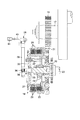
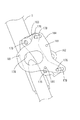
図1に示す自動二輪車1は、フレーム2を備えている。フレーム2は、ステアリングヘッドパイプ3、メインフレーム部材4及びダウンチューブ5を有している。ステアリングヘッドパイプ3は、フロントフォーク6を支持している。フロントフォーク6の上端には、前輪7を操舵するバーハンドル8が固定されている。バーハンドル8の左端部には、操作子の一例であるクラッチレバー9が取り付けられている。
(First embodiment)
A
メインフレーム部材4は、ステアリングヘッドパイプ3から後方に向けて延びている。メインフレーム部材4は、燃料タンク10及びシート11を支持している。ダウンチューブ5は、メインフレーム部材4の前端から下向きに延びる第1の部分5aと、第1の部分5aの下端から後方に向けて延びる第2の部分5bとを有している。
The
フレーム2は、V型二気筒エンジン13を支持している。エンジン13は、クランクケース14、前シリンダ15及び後シリンダ16を有している。前シリンダ15及び後シリンダ16は、クランクケース14の上面から上方の燃料タンク10に向けて突出している。
The
フレーム2のダウンチューブ5は、エンジン13を抱え込んでいる。ダウンチューブ5の第1の部分5aは、エンジン13の直前を通って上下方向に延びているとともに、ダウンチューブ5の第2の部分5bは、クランクケース14の下方を通って前後方向に延びている。
The down
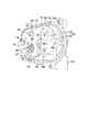
図1及び図2に示すように、クランクケース14は、クランク軸17及び湿式多板形の摩擦クラッチ18を収容している。クランク軸17は、車幅方向に沿って水平に配置されており、その左端部に減速小歯車19が固定されている。摩擦クラッチ18は、減速小歯車19の後方であり、かつクランクケース14の左端部に位置している。摩擦クラッチ18は、クランクケース14の左側面に取り付けたクラッチカバー20によって覆われている。
As shown in FIGS. 1 and 2, the
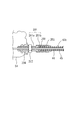
摩擦クラッチ18は、クランク軸17のトルクをトランスミッションの入力軸21に伝えたり遮断するためのものであり、運転者がクラッチレバー9を手で握ることにより人為的に操作される。図2に示すように、摩擦クラッチ18は、クラッチハウジング23、クラッチボス24、複数のフリクションプレート25、複数のクラッチプレート26、クラッチスプリング27及びクラッチレリーズ機構28を備えている。
The
クラッチハウジング23は、入力軸21の左端部に軸受30を介して回転自在に支持されている。クラッチハウジング23の一端には、減速大歯車31が同軸状に連結されている。減速大歯車31は、減速小歯車19と噛み合っている。この噛み合いにより、クランク軸17のトルクがクラッチハウジング23に伝わるようになっている。
The
クラッチボス24は、入力軸21と一体に回転するように入力軸21の左端部に固定されている。クラッチボス24は、クラッチハウジング23によって取り囲まれているとともに、クラッチカバー20に向けて突出する複数のボス部32(図2では一つのみを図示)を有している。
The
フリクションプレート25は、クラッチハウジング23の外周部に支持されている。フリクションプレート25は、クラッチハウジング23と一体に回転するとともに、入力軸21の軸方向に間隔を存して同軸状に並んでいる。
The
クラッチプレート26は、クラッチボス24の外周部に支持されている。クラッチプレート26は、クラッチボス24と一体に回転するとともに、個々にフリクションプレート25の間に入り込んでいる。そのため、フリクションプレート25とクラッチプレート26とは、クラッチハウジング23の内側で交互に並んでいる。
The
本実施の形態では、クラッチスプリング27としてダイヤフラムスプリングを用いている。クラッチスプリング27は、クラッチハウジング23やクラッチボス24の左側に位置するとともに、ボス部32の先端に支持されている。クラッチスプリング27は、プレッシャプレート33を介してフリクションプレート25をクラッチプレート26に常に押し付けている。これにより、フリクションプレート25とクラッチプレート26との間に摩擦力が発生し、摩擦クラッチ18がトルクの伝達を可能とするクラッチインの状態に保たれている。
In the present embodiment, a diaphragm spring is used as the
クラッチレリーズ機構28は、クラッチスプリング27によるフリクションプレート25の押圧を解除するためのものである。本実施形態のクラッチレリーズ機構28は、ラック&ピニオン式のものである。クラッチレリーズ機構28は、ラック36を有するプッシュロッド37と、ピニオン38を有するプッシュレバー軸39とを備えている。
The
プッシュロッド37は、プレッシャプレート33の中心部に軸受35を介して回転自在に支持されており、入力軸21と同軸状に並んでいる。さらに、プッシュロッド37は、入力軸21に近づいたり遠ざかる方向にスライド可能にクラッチカバー20に支持されている。
The
プッシュレバー軸39は、クラッチカバー20に回動可能に支持されている。プッシュレバー軸39は、プッシュロッド37と直交するように鉛直方向に沿って延びているとともに、そのピニオン38がプッシュロッド37のラック36と噛み合っている。プッシュレバー軸39の上端は、クラッチカバー20の上方に突出している。プッシュレバー軸39の上端には、プッシュレバー40の一端が固定されている。プッシュレバー40は、プッシュレバー軸39の上端から水平に延びているとともに、その他端にワイヤ連結部41を有している。
The
プッシュレバー40のワイヤ連結部41は、クラッチワイヤ43(図1参照)を介してクラッチレバー9に連結されている。運転者がクラッチレバー9を手で握ると、クラッチワイヤ43を介してプッシュレバー40の他端が引っ張られ、プッシュレバー軸39が回動する。プッシュレバー軸39の回動は、ピニオン38とラック36との噛み合いにより直線運動に変換される。そのため、プレッシャプレート33がクラッチスプリング27の付勢力に抗してフリクションプレート25から遠ざかる方向にスライドし、フリクションプレート25とクラッチプレート26との圧着が解除される。この結果、摩擦クラッチ18がトルクの伝達を遮断するクラッチオフの状態に移行する。なお、これらプッシュレバー軸39、プッシュレバー40、及びクラッチワイヤ43等は、クラッチレバー9の操作力を摩擦クラッチ18に伝える伝達部材を構成している。
The
したがって、クラッチレバー9は、摩擦クラッチ18がクラッチインの状態を保つ戻し位置と、摩擦クラッチ18がクラッチオフとなる遮断位置との間で回動可能となっている。さらに、戻し位置からクラッチレバー9の先端で例えば10〜15mmの回動範囲は、クラッチレバー9を握ってもクラッチオフの状態が保たれるいわゆる遊びとなっている。この遊びの領域では、クラッチレバー9を操作してもクラッチワイヤ43が僅かに引っ張られるだけであり、クラッチスプリング27の付勢力がクラッチレバー9に伝わることはない。クラッチレバー9の遊びの終端は、遮断開始位置となっている(図15参照)。この遮断開始位置では、クラッチスプリング27の付勢力がクラッチワイヤ43を介してクラッチレバー9に作用する。
Therefore, the clutch lever 9 is rotatable between a return position where the
図15は、クラッチレバー9を戻し位置から遮断位置に回動させた時のクラッチワイヤ43のストローク量とワイヤ荷重との関係を示している。この図15において、特性Xは、クラッチスプリング27を介してプッシュレバー40に加わる荷重の推移を示している。
FIG. 15 shows the relationship between the stroke amount of the
この特性Xから明らかなように、クラッチレバー9が戻し位置から遮断開始位置に達した時点で、プッシュレバー40には、クラッチスプリング27による荷重(反力)が作用する。この荷重は、クラッチワイヤ43のストローク量の増大に追従して一気に立ち上がるとともに、クラッチレバー9が遮断開始位置と遮断位置との間の中間位置に達した以降は略一定に保たれる。なお、本実施形態では、プッシュレバー40に加わる荷重が略一定となる位置は、遮断開始位置と遮断位置との間の中間位置であった。しかしながら、プッシュレバー40の設定状態や摩擦クラッチ18の種類等によって、当該荷重が略一定となる位置は中間位置以外の中途位置になる場合もある。上記荷重が略一定となる中途位置は、中間位置に限定される訳ではない。このプッシュレバー40に加わる荷重は、クラッチワイヤ43を介してクラッチレバー9に伝わる。よって、摩擦クラッチ18のトルク容量を高めるためにクラッチスプリング27の取り付け荷重を大きく設定した場合には、クラッチレバー9の操作が重くなる。
As is clear from this characteristic X, when the clutch lever 9 reaches the disconnection start position from the return position, a load (reaction force) by the
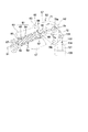
このクラッチレバー9を操作するときの負担を軽減するため、本実施の形態では、クラッチワイヤ43の途中に操作補助装置50を介在させている。図1に示すように、クラッチワイヤ43は、クラッチレバー9からバーハンドル8の前方を通して下向きに導かれた後、エンジン13の左側方を通して後方の摩擦クラッチ18に導かれている。このため、クラッチワイヤ43は、エンジン13の左側方においてその引き回し方向が大きく変化するように曲がっており、このクラッチワイヤ43が曲がる部分に上記操作補助装置50が位置している。
In order to reduce the burden when operating the clutch lever 9, the
クラッチワイヤ43は、クラッチレバー9に接続された第1のクラッチワイヤ43aと、プッシュレバー40に接続された第2のクラッチワイヤ43bとで構成され、これら第1のクラッチワイヤ43aと第2のクラッチワイヤ43bとが操作補助装置50を介して互いに連結されている。第1のクラッチワイヤ43aは、クラッチレバー9と操作補助装置50との間に跨っている。第2のクラッチワイヤ43bは、クラッチレリーズ機構28のプッシュレバー40と操作補助装置50との間に跨っている。
The
図4に示すように、第1のクラッチワイヤ43a及び第2のクラッチワイヤ43bは、夫々金属製のインナーワイヤと、このインナーワイヤ44を覆う合成樹脂製のアウターチューブ45とを備えている。インナーワイヤ44は、アウターチューブ45に摺動可能に接しているとともに、アウターチューブ45の両端からアウターチューブ45の外に引き出されている。
As shown in FIG. 4, each of the first
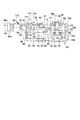
図3ないし図7に示すように、操作補助装置50は、外装ケース51と、この外装ケース51に収容されたアシスト機構52とを備えている。外装ケース51は、例えばアルミニウム合金のような金属材料で構成されている。外装ケース51の表面には、外観品質を高めるためのめっき処理が施されている。なお、外装ケース51の表面は塗装されていてもよい。
As shown in FIGS. 3 to 7, the
外装ケース51は、ケース本体53とケースカバー54とを有している。ケース本体53は、例えばエンジン13の左側方に向けて開口する皿状であり、例えばダウンチューブ5の第1の部分5aに図示しないブラケットを介して保持されている。ケースカバー54は、ケース本体53に複数のボルト55を介して固定されており、ケース本体53の開口端を覆っている。さらに、外装ケース51は、自動二輪車1を左側方から見た時に、プッシュレバー40と略同じ高さとなる位置に設置されている。
The
図3及び図7に示すように、ケースカバー54は、第1のガイド部として、一対の第1のワイヤ導入口95a,95bを有している。また、ケースカバー54は、第2のガイド部として、単一の第2のワイヤ導入口96を有している。第1及び第2の導入口95a,95b,96は、外装ケース51の内部に開口している。一方の第1のワイヤ導入口95aは、ケースカバー54の前端上部から上向きに突出している。他方の第1のワイヤ導入口95bは、ケースカバー54の前端の中間部から前方斜め上向きに突出している。第2のワイヤ導入口96は、ケースカバー54の後端下部から後方に向けて突出している。
As shown in FIGS. 3 and 7, the case cover 54 has a pair of
本実施の形態では、第1のクラッチワイヤ43aは、一方の第1のワイヤ導入口95aに差し込まれている。この差し込みにより、第1のクラッチワイヤ43aのインナーワイヤ44が外装ケース51の内部に導かれて、第1の回動部材57に連結されている。この第1のクラッチワイヤ43aは、外装ケース51の前端からダウンチューブ5の第1の部分5aに沿って上向きに導かれている(図1参照)。
In the present embodiment, the first
他方の第1のワイヤ導入口95bは、外装ケース51に対する第1のクラッチワイヤ43aの引き出し方向を変えたい時に用いるものである。この他方の第1のワイヤ導入口95bは、未使用時に図示しない防塵キャップで覆い、外装ケース51の内部に塵埃や異物が侵入するのを防止することが望ましい。
The other first
第2のクラッチワイヤ43bは、第2のワイヤ導入口96に差し込まれている。この差し込みにより、第2のクラッチワイヤ43bのインナーワイヤ44が外装ケース51の内部に導かれて、第1の回動部材57に連結されている。第2のクラッチワイヤ43bは、外装ケース51の後端からエンジン13の左側を通して後方に導かれており、アシスト機構52の第1の回動部材57とプッシュレバー40とを一直線状に結んでいる(図1参照)。このため、第1のクラッチワイヤ43aと第2のクラッチワイヤ43bとは、アシスト機構52を間に挟んで互いに異なる方向に延びている。
The second
図4ないし図9に示すように、アシスト機構52は、第1の回動部材57、第2の回動部材58及びスプリングユニット59を備えている。第1の回動部材57は、例えば板金プレス加工部品で構成されている。第1の回動部材57は、ピボット部60、ワイヤ連結部61及びレバー部62を有している。
As shown in FIGS. 4 to 9, the
ピボット部60は、ワイヤ連結部61とレバー部62との間に位置するとともに、第1のピボット軸63を介してケース本体53のボス部64(図6及び図9参照)に回動可能に支持されている。第1のピボット軸63のボス部64とは反対側の端部は、ケースカバー54の軸受部65に支持されている。
The
図4に示すように、第1の回動部材57のワイヤ連結部61は、ケース本体53の前半部(図4の左半部)に位置している。ワイヤ連結部61は、下縁部67を有している。下縁部67は、第1のピボット軸63を中心とする円弧を描くように湾曲している。言い換えると、第1の回動部材57の下縁部67は、外装ケース51を左側方から見たときに、第1のワイヤ導入口95aと第2のワイヤ導入口96との間を結ぶ円弧状の軌跡Aに沿うように湾曲している。このため、ワイヤ連結部61の下縁部67は、軌跡Aに沿うように回動する。
As shown in FIG. 4, the
ワイヤ連結部61の下縁部67は、係合溝68(図8参照)と係合孔69とを有している。係合溝68は、上記第1のクラッチワイヤ43aのインナーワイヤ44及び第2のクラッチワイヤ43bのインナーワイヤ44が巻き掛けられるものであり、下縁部67の外周面に開口している。係合孔69は、下縁部67の周方向に沿う長孔状をなしている。係合孔69は、下縁部67の外周面及び係合溝68に開口している。この係合孔69の開口縁部には、各インナーワイヤ44の先端に固定した円柱状の係合子70が引っ掛かっている。
The
そのため、第1のクラッチワイヤ43aのインナーワイヤ44と第2のクラッチワイヤ43bのインナーワイヤ44とは、第1の回動部材57を介して一体的に連結されている。この連結により、第1のクラッチワイヤ43aのインナーワイヤ44と第2のクラッチワイヤ43bのインナーワイヤ44とは、外装ケース51の内部において第1の回動部材57の下縁部67が描く軌跡Aに沿って移動するようになっている。そして、第1及び第2のクラッチワイヤ43a,43bのインナーワイヤ44の移動量は、互いに等しくなっている。
Therefore, the
レバー部62は、ケース本体53の後半部に位置している。このレバー部62には、カム溝71が形成されている。図4に示すように、カム溝71は円弧状の長孔であり、上記ワイヤ連結部61の下縁部67とは逆向きに湾曲している。
The
第2の回動部材58は、リンクプレート72とリンクレバー73とを有している。リンクプレート72及びリンクレバー73は、例えば板金プレス加工部品で構成され、第1の回動部材57のレバー部62を間に挟んで互いに平行に配置されている。リンクプレート72は、第2のピボット軸74を介してケース本体53のボス部75(図6参照)に回動可能に支持されている。リンクレバー73は、第3のピボット軸76を介してケースカバー54の軸受部77に回動可能に支持されている。第2のピボット軸74と第3のピボット軸76とは、互いに同軸状に並んでいる。
The second rotating
リンクプレート72及びリンクレバー73は、第1及び第2のピン78a,78bを介して一体的に結合されている。第1のピン78aは、第1の回動部材57のカム溝71を貫通している。この第1のピン78aに、例えばローラからなるカムフォロア79が回転自在に支持されている。カムフォロア79は、カム溝71内に入り込むとともに、このカム溝71の内面に接している。
The
このため、カム溝71及びカムフォロア79は、第1の回動部材57の動きを第2の回動部材58に伝えたり、逆に第2の回動部材58の動きを第1の回動部材57に伝えるようになっている。カム溝71及びカムフォロア79は、カム機構を形成している。
For this reason, the
図5に示すように、スプリングユニット59は、スプリングホルダ81と補助スプリング82とを備えている。スプリングホルダ81は、内筒83と外筒84とで構成されている。内筒83及び外筒84は、軸方向にスライド可能に嵌合されており、この嵌合により、スプリングホルダ81が伸縮可能となっている。
As shown in FIG. 5, the
内筒83は、スプリング受け85と枢支端部86とを有している。スプリング受け85は、内筒83の一端部の外周面からフランジ状に張り出している。枢支端部86は、内筒83の一端に位置するとともに、ケース本体53の前端部に形成した取り付け座87に回動可能に支持されている。
The
外筒84は、スプリング受け88と連結端部89とを有している。スプリング受け88は、外筒84の一端部の外周面からフランジ状に張り出している。連結端部89は、外筒84の一端に位置するとともに、ピン90を介して第2の回動部材58のリンクプレート72に回動可能に連結されている。このため、スプリングホルダ81は、ケース本体53の前端部とリンクプレート72との間に掛け渡されて、ケース本体53の前後方向に延びている。
The
補助スプリング82は、圧縮コイルスプリングであり、内筒83のスプリング受け85と外筒84のスプリング受け88との間に圧縮状態で介在している。このため、スプリングホルダ81は、常に伸長する方向に付勢されている。そして、クラッチレバー9が遮断開始位置にある状態では、図11に示すように、スプリングホルダ81の枢支端部86と、連結端部89と、第2の回動部材58の回動中心となる第2、第3のピボット軸74,76とが、同一の直線S1上に並ぶようになっている。
The
図4及び図5は、クラッチレバー9が戻し位置にあるときのアシスト機構52の状態を示している。クラッチレバー9が戻し位置にあるときには、リンクプレート72の第2のピボット軸74及びリンクレバー73の第3のピボット軸76は、スプリングホルダ81の枢支端部86と連結端部89との間を結ぶ直線S1よりも下にずれている。さらに、スプリングユニット59は、スプリングホルダ81の連結端部89が枢支端部86よりも上方に位置するように傾斜している。加えて、リンクプレート72のカム溝71は、ケース本体53の前後方向に延びるとともに、上向きに凸となるような姿勢に保たれている。
4 and 5 show the state of the
運転者がクラッチレバー9を戻し位置から遮断開始位置に操作すると、第1のクラッチワイヤ43aを介して第1の回動部材57が上向きに引っ張られ、図10及び図11に矢印で示すように第1の回動部材57が時計回り方向に回動する。この回動により、カム溝71を有するレバー部62が下向きに移動する。このため、カム溝71に接しているカムフォロア79がケース本体53の前方に押されるような力を受け、リンクプレート72及びリンクレバー73が反時計回り方向に回動する。この結果、スプリングユニット59が枢支端部86を支点に下向きに回動する。
When the driver operates the clutch lever 9 from the return position to the disconnection start position, the first rotating
クラッチレバー9が遮断開始位置に達すると、図11に示すように、スプリングホルダ81の枢支端部86と連結端部89とを結ぶ直線S1上に第2及び第3のピボット軸74,76が位置する。よって、リンクプレート72及びリンクレバー73に補助スプリング82の付勢力が加わっていても、この付勢力によってリンクプレート72及びリンクレバー73が回動することはない。
When the clutch lever 9 reaches the disconnection start position, as shown in FIG. 11, the second and
クラッチレバー9を遮断開始位置から遮断位置に向けて操作すると、第1の回動部材57が時計回り方向にさらに回動する。この回動により、カム溝71を有するレバー部62が下向きに移動するとともに、カム溝71の姿勢が縦向きとなるように変化する。よって、カム溝71に接しているカムフォロア79がケース本体53の前方斜め下向きに押されるような力を受け、リンクプレート72及びリンクレバー73が反時計回り方向に回動する。
When the clutch lever 9 is operated from the disconnection start position toward the disconnection position, the first rotating
本実施の形態では、クラッチレバー9を遮断開始位置から遮断位置に操作すると、スプリングユニット59が枢支端部86を支点に下向きに回動し、スプリングユニット59の枢支端部86と連結端部89とを結ぶ直線S1がリンクプレート72及びリンクレバー73の回動中心の下にずれる。
In this embodiment, when the clutch lever 9 is operated from the disconnection start position to the disconnection position, the
このため、補助スプリング82の付勢力を受けるスプリングホルダ81が伸長し、この補助スプリング82の付勢力が、リンクプレート72及びリンクレバー73を回動させる力として作用する。したがって、クラッチレバー9が遮断開始位置を越えて遮断位置に近づく方向に操作されたときは、リンクプレート72及びリンクレバー73が補助スプリング82によって強制的に反時計回り方向に回動される。よって、運転者がクラッチレバー9を握る際の操作力に、補助スプリング82の付勢力が付加されることになる。したがって、クラッチレバー9を操作する際の運転者の負担が軽減される。
For this reason, the
本実施の形態によると、カム溝71は、リンクプレート72及びリンクレバー73がスプリングユニット59からの付勢力を受けて反時計回り方向に動くタイミングを規定している。詳しく述べると、カム溝71は、クラッチレバー9が遮断開始位置と遮断位置との間の中間位置から遮断位置に近づく方向に操作されるときに、リンクプレート72及びリンクレバー73から第1の回動部材57に加わる補助スプリング82の付勢力を一定の範囲内に保つような形状を有している。
According to the present embodiment, the
言い換えると、カム溝71は、クラッチレバー9が遮断開始位置から中間位置に達するまでの期間中は、リンクプレート72及びリンクレバー73の動きを許容し、クラッチレバー9が中間位置を越えて遮断位置に達するまでの期間中は、リンクプレート72及びリンクレバー73の動きを抑えて補助スプリング82の自由な伸長を制限するような形状を有している。したがって、本実施の形態では、カム溝71及びカムフォロア79からなるカム機構は、第1の回動部材57に加わる補助スプリング82の付勢力を制御している。
In other words, the
図15において、符号Yで示す特性は、摩擦クラッチ18を遮断する方向にクラッチレバー9を操作したときのクラッチレバー9に加わる荷重の移り変わりを示している。この特性Yから明らかなように、クラッチレバー9が遮断開始位置を越えて遮断位置に達するまでの全ての領域において、クラッチレバー9に加わる荷重は、プッシュレバー40に加わるクラッチスプリング27の荷重よりも低くなっている。この理由は、第1のクラッチワイヤ43aからの入力によってリンクプレート72が反時計回り方向に回動されるときに、このリンクプレート72を反時計回り方向に強制的に回動させようとする補助スプリング82の付勢力が付加されるからである。
In FIG. 15, a characteristic indicated by a symbol Y indicates a change in load applied to the clutch lever 9 when the clutch lever 9 is operated in a direction in which the
さらに、本実施の形態では、カム溝71の形状を上記のように規定したことにより、クラッチレバー9が遮断開始位置と遮断位置との間の中間位置から遮断位置に達するまでの期間中、クラッチレバー9に加わる荷重が略一定に保たれている。この結果、図15に示すように、プッシュレバー40に加わる荷重と、クラッチレバー9に加わる荷重とは、ワイヤストローク量に対して同じような特性を有して変化することになる。
Furthermore, in the present embodiment, the shape of the
前述したように、クラッチレバー9が戻し位置にある状態では、図4及び図5に示すように、リンクプレート72の第2のピボット軸74及びリンクレバー73の第3のピボット軸76は、スプリングホルダ81の枢支端部86と連結端部89との間を結ぶ直線S1よりも下にずれている。このため、リンクプレート72及びリンクレバー73は、補助スプリング82の付勢力により時計回り方向、すなわち摩擦クラッチ18を遮断するときとは逆向きの方向に付勢される。
As described above, when the clutch lever 9 is in the return position, as shown in FIGS. 4 and 5, the
このリンクプレート72を時計回り方向に付勢する力は、クラッチレバー9を戻し位置から遮断開始位置まで回動させる力に対抗する逆アシスト力となる。この結果、このままではクラッチレバー9を最初に握る時の初期入力荷重が増えてしまい、クラッチレバー9の操作性に悪影響を及ぼす。
The force that urges the
このことから、本実施の形態の操作補助装置50では、外装ケース51のケース本体53に相殺スプリングユニット100が組み込まれている。図4及び図14に示すように、ケース本体53は、相殺スプリングユニット100を収めるハウジング部101を有している。ハウジング部101は、ケース本体53の後端下部に位置し、上記第2のワイヤ導入口96と並んでいる。
Therefore, in the
図14に示すように、ハウジング部101は、上下方向に延びるシリンダ102を有している。シリンダ102の上端には、外装ケース51の内部に開口する開口102aが形成されている。開口102aは、リンクプレート72に固定されたロックピン103と向かい合っている。ロックピン103は、リンクプレート72とスプリングユニット59との連結端部89に対し、第2のピボット軸74を間に挟んだ反対側に位置している。
As shown in FIG. 14, the
図14に示すように、相殺スプリングユニット100は、押圧ピン104と相殺スプリング105とを有している。押圧ピン104は、上端が閉塞された中空状をなしており、この押圧ピン104の下端にフランジ状のストッパ106が形成されている。押圧ピン104は、ハウジング部101の下方からシリンダ102内に摺動可能に挿入されている。
As shown in FIG. 14, the canceling
ハウジング部101の下端部には、サークリップ107を介してスプリング受け108が固定されている。スプリング受け108は、シリンダ102の下方に位置している。
A
相殺スプリング105は、圧縮コイルスプリングであり、押圧ピン104の上端内面とスプリング受け108との間に圧縮状態で介在している。相殺スプリング105は、押圧ピン104を常に上向きに付勢している。この相殺スプリング105の付勢力は、補助スプリング82による逆アシスト力よりも僅かに小さく設定されている。
The canceling
押圧ピン104は、その上端がシリンダ102の開口102aから大きく突出する第1の位置と、押圧ピン104の上端がシリンダ102の開口102aから僅かに突出する第2の位置との間で弾性的に移動可能となっている。第1の位置では、押圧ピン104のストッパ106がシリンダ102の下端に突き当り、押圧ピン104の位置規制がなされている。同様に第2の位置では、押圧ピン104のストッパ106がスプリング受け108に突き当り、押圧ピン104の位置規制がなされている。
The
クラッチレバー9が戻し位置から遮断開始位置に達するまでの期間中は、図5及び図11に示すように、押圧ピン104の上端がリンクプレート72のロックピン103に下方から突き当たっている。そのため、リンクプレート72は、ロックピン103を介して相殺スプリング105の付勢力を受けている。この結果、クラッチレバー9が遊びの範囲内にあるときに、リンクプレート72に加わる補助スプリング82及び相殺スプリング105の付勢力の合計がほとんど零となり、リンクプレート72の時計回り方向への回動が制限される。
During the period until the clutch lever 9 reaches the cutoff start position from the return position, the upper end of the
クラッチレバー9が遮断開始位置を通り越して遮断位置に近づくと、図13に示すように、リンクプレート72のロックピン103が押圧ピン104の上端から離脱する。この結果、押圧ピン104が相殺スプリング105の付勢力により第1の位置に保持されるとともに、リンクプレート72及びリンクレバー73が補助スプリング82の付勢力により反時計回り方向に強制的に回動される。
When the clutch lever 9 passes the disconnection start position and approaches the disconnection position, the
図3、図6及び図7に示すように、外装ケース51のケースカバー54は、円形の開口部110を有している。開口部110は、第1の回動部材57のワイヤ連結部61と向かい合っており、この開口部110を通じてワイヤ連結部61の係合溝68や係合孔69が外装ケース51の外方に露出している。言い換えると、開口部110は、ワイヤ連結部61の係合溝68にインナーワイヤ44を引っ掛けたり、インナーワイヤ44の先端の係合子70を係合孔69に引っ掛ける際に、手の指先や工具を差し込むためのものである。そのため、第1の回動部材57に対するインナーワイヤ44の接続作業は、ケース本体53にケースカバー54を固定した状態で行うことが可能である。
As shown in FIGS. 3, 6, and 7, the case cover 54 of the
ケースカバー54は、開口部110の開口縁部から開口部110の中心に向けて延びる支持壁111を有している。支持壁111は、第1の回動部材57のワイヤ連結部61を避けた位置にあり、その先端部にねじ孔112を有するボス部113が形成されている。ねじ孔112の位置は、開口部110の中心と一致している。
The case cover 54 includes a
開口部110は、円盤状の蓋114(図1参照)で覆われている。蓋114は、開口部110に取り外し可能に嵌合されているとともに、ボルト115(図6参照)を介して支持壁111に固定されている。ボルト115は、蓋114の中心を貫通してボス部113のねじ孔112にねじ込まれている。
The
図3及び図9に示すように、第1の回動部材57のワイヤ連結部61には、六角形の挿入孔118が形成されている。挿入孔118は、開口部110の領域内に位置するとともに、クラッチレバー9が正規の遮断開始位置にあるときに、ケース本体53に形成された位置決め用の凹部119と合致するようになっている。このため、例えば六角レンチのような工具を開口部110から挿入孔118内に挿入し、この工具の先端を凹部119に引っ掛けることで、第1の回動部材57を図10の位置に保持することができる。
As shown in FIGS. 3 and 9, a
したがって、クラッチレバー9が正規の遮断開始位置にあるときの第1の回動部材57の位置を規定することができ、この状態でクラッチワイヤ43の遊びの調整作業やインナーワイヤ44の連結作業を行うことができる。
Therefore, the position of the first rotating
本実施の形態によれば、クラッチワイヤ43の途中に設けられたアシスト機構52は、クラッチレバー9が遮断開始位置と遮断位置との間の中間位置から遮断位置に達するまでの期間中、第1の回動部材57を介してクラッチワイヤ43に加わる補助スプリング82の付勢力を一定の範囲内に保っている。言い換えると、アシスト機構52は、クラッチレバー9が遮断位置に近づくに従い、クラッチワイヤ43に加わる補助スプリング82の付勢力が増大するのを打ち消している。
According to the present embodiment, the
このため、クラッチレリーズ機構28のプッシュレバー40に加わるクラッチスプリング27の荷重と、アシスト機構52を経てクラッチレバー9に加わる実際の荷重とは、ワイヤストローク量に対し同じような特性で変化する。
For this reason, the load of the
この結果、摩擦クラッチ18を遮断する際に、クラッチワイヤ43に補助スプリング82の付勢力を付加する構成としたにも拘らず、クラッチレバー9が遮断位置に近づいたときにクラッチレバー9の操作が急激に軽くなるのを防止できる。したがって、クラッチレバー9の操作力を軽減しつつ、従来と同等の操作感覚でクラッチレバー9を操作することができる。よって、クラッチレバー9の操作に違和感が生じることを回避でき、クラッチレバー9の操作性が向上する。
As a result, when the
さらに、本実施の形態によると、第1のクラッチワイヤ43aと第2のクラッチワイヤ43bとは、一対一の関係を保って移動する。このため、摩擦クラッチ18の構成を何等変更することなしに、クラッチレバー9の動きをプッシュレバー40に伝える経路にアシスト機構52を介在させることができる。
Furthermore, according to the present embodiment, the first
さらに、第1のクラッチワイヤ43aのインナーワイヤ44と第2のクラッチワイヤ43bのインナーワイヤ44とは、第1の回動部材57の円弧状に湾曲する下縁部67に巻き掛けた状態で第1の回動部材57に連結されている。この下縁部67は、第1のワイヤ導入口95aと第2のワイヤ導入口96との間を結ぶ円弧状の軌跡Aに沿うように湾曲するとともに、この軌跡Aに沿って回動する。そのため、第1の回動部材57の回動によって、インナーワイヤ44が曲がる方向をガイドすることができる。
Further, the
加えて、第1および第2のクラッチワイヤ43a,43bは、それぞれのインナーワイヤ44のみが外装ケース51の内部に導入され、これらインナーワイヤ44が第1の回動部材57の下縁部67に巻き掛けられている。このため、インナーワイヤ44が円弧状に湾曲する部分にアウターチューブ45は存在せず、インナーワイヤ44がアウターチューブ45に強く押し付けられずに済む。
In addition, only the
それとともに、第2のクラッチワイヤ43bは、クラッチレリーズ機構28のプッシュレバー40に向けて真っ直ぐに延びているので、そのインナーワイヤ44とアウターチューブ45との間に生じる摺動抵抗を小さく抑えることができる。
At the same time, the second
このことから、クラッチワイヤ43が曲がる部分にアシスト機構52を設けることで、クラッチレバー9を操作したときにクラッチワイヤ43に加わる抵抗を低減することができる。したがって、クラッチワイヤ43の引き回し方向がエンジン13の左側方で大きく変化するにも拘らず、クラッチワイヤ43の動きが滑らかとなり、摩擦クラッチ18を遮断するときにクラッチワイヤ43に付加されるアシスト機構52の付勢力が打ち消されずに済む。
Therefore, by providing the
よって、アシスト機構52が持つ本来の援助機能を十分に発揮させることができ、摩擦クラッチ18を遮断するときのクラッチレバー9の操作性を改善することができる。
Therefore, the original assist function of the
(第2実施形態)
図16〜図25に示すように、第2実施形態は第1実施形態に係る操作補助装置50に変更を加えたものであり、第1実施形態の操作補助装置50をより小型化したものである。以下の説明では、第1実施形態と対応する要素には同一の符号を付すこととする。
(Second Embodiment)
As shown in FIGS. 16-25, 2nd Embodiment adds the change to the
図16〜図18に示すように、第2実施形態においても、操作補助装置50は、外装ケース51とアシスト機構52とを備えている。外装ケース51は、ケース本体53とケースカバー54とから構成されている。ただし、第2実施形態では、第1実施形態に比べて、ケース本体53及びケースカバー54の側面視の面積が小さくなっている。
As shown in FIGS. 16 to 18, also in the second embodiment, the
図16及び図18に示すように、ケース本体53及びケースカバー54には、ボルト孔が形成された第1、第2及び第3の締結部151,152,153が設けられている。ケース本体53とケースカバー54とは、これら締結部151,152,153においてボルト115によって固定されている。
As shown in FIGS. 16 and 18, the case
図18に示すように、アシスト機構52は、第1の回動部材57と、第2の回動部材58と、スプリングユニット59と、相殺スプリングユニット100とを備えている。
As shown in FIG. 18, the
第1の回動部材57は、ピボット部60とワイヤ連結部61とを有している。図4に示すように、第1実施形態に係る第1の回動部材57は、ワイヤ連結部61とは別に、カム溝71が形成されたレバー部62を有していた。これに対し、図18に示すように、第2実施形態に係る第1の回動部材57では、レバー部62は省略されており、カム溝71はワイヤ連結部61に形成されている。本実施形態では、レバー部62が省略されているので、第1の回動部材57の面積が小さくなっている。第1の回動部材57は、第1のピボット軸63の軸方向から見て、中心角が120度よりも小さな略扇形に形成されている。ただし、第1の回動部材57の形状は特に限定されず、例えば、三角形状等の他の形状に形成されていてもよい。また、第1の回動部材57は、更に小型化されていてもよく、例えば中心角が90度よりも小さな略扇形に形成されていてもよい。
The first rotating
図24に示すように、ピボット部60は、第1のピボット軸63を介してケース本体53のボス部64に回動自在に支持されている。第1のピボット軸63のボス部64とは反対側の端部は、ケースカバー54の軸受部65に支持されている。
As shown in FIG. 24, the
図18及び図25に示すように、ワイヤ連結部61の下縁部の一端側には、第1の係合溝68a及び第1の係合孔69aが形成されている。ワイヤ連結部61の下端部の他端側には、第2の係合溝68b及び第2の係合孔69bが形成されている。
As shown in FIGS. 18 and 25, a
第1の係合溝68aには、第1のクラッチワイヤ43aのインナーワイヤ44が巻き掛けられている。第1の係合溝68aは、下縁部の外周面に開口している。第1の係合孔69aは、円形に形成されている。第1の係合孔69aは、下縁部の外周面及び第1の係合溝68aに開口している。第1のクラッチワイヤ43aのインナーワイヤ44の先端には、円柱状の係合子70aが設けられている。この係合子70aは、第1の係合孔69aの開口縁部に引っ掛けられている。これにより、第1のクラッチワイヤ43aのインナーワイヤ44とワイヤ連結部61とが係合している。
The
第2の係合溝68bには、第2のクラッチワイヤ43bのインナーワイヤ44が巻き掛けられている。第2の係合溝68bは、下縁部の外周面に開口している。第2の係合孔69bも、円形に形成されている。第2の係合孔69bは、下縁部の外周面及び第2の係合溝68bに開口している。第2の係合孔69bの開口縁部には、第2のクラッチワイヤ43bのインナーワイヤ44の先端に固定された円柱状の係合子70bが引っ掛けられている。これにより、第2のクラッチワイヤ43bのインナーワイヤ44とワイヤ連結部61とが係合している。
The
第1の係合溝68a及び第2の係合溝68bは、それぞれ第1のピボット軸63を中心とする円弧を描くように湾曲している。第1のクラッチワイヤ43aのインナーワイヤ44と第2のクラッチワイヤ43bのインナーワイヤ44とは、第1の回動部材57を介して一体的に連結されている。これにより、第1のクラッチワイヤ43aのインナーワイヤ44と第2のクラッチワイヤ43bのインナーワイヤ44とは一体的に移動し、それらインナーワイヤ44の互いの移動量の割合が一定となっている。また、第1のピボット軸63から係合子70aまでの距離と第1のピボット軸63から係合子70bまでの距離とが等しいため、それらインナーワイヤ44の移動量は互いに等しくなっている。
The
カム溝71は、第1の係合孔69aと第2の係合孔69bとの間に設けられている。カム溝71は、第1の係合孔69aの側が凹んだ湾曲形状の長孔によって形成されている。
The
第1の実施形態に係る第2の回動部材58は、リンクプレート72とリンクレバー73とから構成されていた(図4参照)。それに対し、図19に示すように、本実施形態に係る第2の回動部材58は、リンクプレート72のみによって構成されている。リンクプレート72は、第1の回動部材57の裏側に配置されている。リンクプレート72は、第2のピボット軸74を介してケース本体53のボス部75(図24参照)に回動自在に支持されている。
The second rotating
リンクプレート72には、表側に突出する第1のピン78aが結合されている。第1のピン78aには、例えばローラからなるカムフォロア79が回転自在に支持されている。カムフォロア79は、カム溝71内に配置され、カム溝71の内面に接している。
The
このため、カム溝71及びカムフォロア79は、第1の回動部材57又は第2の回動部材58の回動に伴って、第1の回動部材57から第2の回動部材58に力を伝達し、あるいは、第2の回動部材58から第1の回動部材57に力を伝達する。カム溝71及びカムフォロア79は、カム機構を構成している。
For this reason, the
スプリングユニット59の構成は第1実施形態と同様である。ただし、本実施形態では、スプリングユニット59の位置及び取付姿勢が異なっている。図21に示すように、本実施形態では、スプリングユニット59の枢支端部86を支持する取り付け座87は、ケース本体53の後端部(図21の右端部)に設けられている。スプリングユニット59は、ケース本体53の後端部から前方ないし斜め前方(図23参照)に向かって延びている。
The configuration of the
図19に示すように、スプリングユニット59の連結端部89は、ピン90を介して第2の回動部材58のリンクプレート72に回動自在に連結されている。クラッチレバー9が遮断開始位置にある状態(図19に示す状態)では、スプリングホルダ81の枢支端部86と、連結端部89と、第2の回動部材58の回動中心となる第2のピボット軸74とは、同一の直線S1上に位置することになる。
As shown in FIG. 19, the connecting
図20及び図21は、クラッチレバー9が戻し位置にあるときのアシスト機構52の状態を示している。クラッチレバー9が戻し位置にあるときは、図21に示すように、リンクプレート72の第2のピボット軸74は、スプリングホルダ81の枢支端部86と連結端部89とを結ぶ直線S1よりも上方にずれている。カムフォロア79は、カム溝71の左側に位置している。
20 and 21 show the state of the
運転者がクラッチレバー9を戻し位置から遮断開始位置に向けて操作すると、第1のクラッチワイヤ43aを介して第1の回動部材57が上向きに引っ張られ、第1の回動部材57は第1のピボット軸63を中心として時計回り方向に回動する。この回動により、カム溝71もピボット軸63を中心として時計回り方向に回動し、上向きに移動する。このため、カム溝71に接しているカムフォロア79は上向きに押されるような力を受け、リンクプレート72は、第2のピボット軸74を中心として反時計回り方向に回動する。この結果、スプリングユニット59は、枢支端部86を支点として時計回り方向に回動する。
When the driver operates the clutch lever 9 from the return position toward the disconnection start position, the first rotating
クラッチレバー9が遮断開始位置に達すると、図19に示すように、スプリングホルダ81の枢支端部86と連結端部89とを結ぶ直線S1上に、第2のピボット軸74が位置する。そのため、補助スプリング82の付勢力がリンクプレート72を回動させるように作用することはない。
When the clutch lever 9 reaches the disconnection start position, the
クラッチレバー9を遮断開始位置から遮断位置に向けて操作すると、第1の回動部材57は時計回り方向にさらに回動する。この回動により、カム溝71もピボット軸63を中心としてさらに回動し、上向きに移動する。この際、カム溝71の姿勢は、全体的に横向きとなるように変化する。この結果、カム溝71に接しているカムフォロア79はケース本体53の上方ないし前方に押されるような力を受け、リンクプレート72は反時計回り方向にさらに回動する。
When the clutch lever 9 is operated from the disconnection start position toward the disconnection position, the first rotating
クラッチレバー9を遮断開始位置から遮断位置に操作すると、スプリングユニット59は、枢支端部86を支点として、時計回り方向にさらに回動する。そして、スプリングユニット59の枢支端部86と連結端部89とを結ぶ直線S1は、リンクプレート72の回動中心(ピボット軸74)から上方にずれていく。
When the clutch lever 9 is operated from the disconnection start position to the disconnection position, the
このため、補助スプリング82の付勢力を受けるスプリングホルダ81が伸長し、この補助スプリング82の付勢力がリンクプレート72に伝わり、リンクプレート72を反時計回り方向に回動させる力として作用する。したがって、クラッチレバー9が遮断開始位置を越えて遮断位置に近づく方向に操作されたときは、リンクプレート72が補助スプリング82によって強制的に反時計回り方向に回動される。よって、運転者がクラッチレバー9を握ろうとする操作力に補助スプリング82の付勢力が付加されることになり、クラッチレバー9を操作するときの運転者の負担が軽減される。
For this reason, the
なお、本実施の形態においても、カム溝71は、リンクプレート72がスプリングユニット59からの付勢力を受けて反時計回り方向に動くタイミングを規定している。カム溝71は、遮断開始位置から遮断位置に達する間に、第1の回動部材57の角速度に対する第2の回動部材58の角速度の比である角速度比を変化させるような形状を有している。カム溝71は、クラッチレバー9が遮断開始位置から中間位置に至る間の初期段階において、リンクプレート72を介して第1の回動部材57に伝わる補助スプリング82の付勢力(厳密には、第1の回動部材57を時計回り方向に回動させるモーメント)が、従来のものよりも早く大きくなるような形状を有している。
Also in the present embodiment, the
図34に、補助スプリング82の付勢力Zの変化特性と、従来の付勢力Z0の変化特性とを対比して示す。本アシスト機構52では、付勢力Zの特性曲線の立ち上がり部分の傾斜が従来よりも大きくなっている。
FIG. 34 shows a comparison between the change characteristic of the biasing force Z of the
ここで、従来のものとは、クラッチレリーズ機構に連結された回動部材と補助スプリングとが直接連結され、上記回動部材と補助スプリングとが同じ速度で回動し、上記回動部材の回動にしたがって補助スプリングが自由に伸長するものである(例えば、前述の特許文献1に開示されたもの)。 Here, in the conventional one, the rotating member connected to the clutch release mechanism and the auxiliary spring are directly connected, and the rotating member and the auxiliary spring rotate at the same speed, and the rotating member rotates. The auxiliary spring freely expands according to the movement (for example, disclosed in Patent Document 1).
本アシスト機構52では、第1の回動部材57に対する第2の回動部材58の角速度の比率は、遮断開始位置の方が遮断位置よりも大きくなっている。また、遮断開始位置と中間位置との間の角速度比の平均値は、中間位置と遮断位置との間の角速度比の平均値よりも大きくなっている。なお、上記角速度比は、遮断開始位置から遮断位置に至る間で徐々に小さくなっていってもよい。上記角速度比を適宜に調整することにより、第1の回動部材57に伝わる補助スプリング82の付勢力Z、つまりクラッチレバー9が受けるアシスト力の変化特性を任意に設定することができる。
In the
このように、カム溝71の形状を適宜設定することにより、アシスト力の変化特性を自由に調整することが可能となる。図34に示すように、摩擦クラッチ18のプッシュレバー40に加わる荷重Xは、遮断開始位置の直後では大きく変化し、その後は変化の度合いが小さくなる。本アシスト機構52では、遮断開始位置と中間位置との間において、付勢力Zの特性曲線の立ち上がり部分の傾斜を大きくすることによって、クラッチレバー9に加わる荷重Yを、摩擦クラッチ18のプッシュレバー40に加わる荷重Xとほぼ同様の特性を有するように変化させることとした。すなわち、クラッチレバー9に加わる荷重Yとプッシュレバー40に加わる荷重Xとの比率が一定の範囲内に収まるようにした。これにより、いわゆる半クラッチ操作の際に、クラッチレバー9の操作荷重を低減しつつ、従来と同様の操作感を与えることができる。
Thus, by appropriately setting the shape of the
なお、第1実施形態で説明したように、中間位置と遮断位置との間において、第1の回動部材57に加わるアシスト力は一定の範囲内に保たれる。すなわち、カム溝71は、クラッチレバー9が中間位置から遮断位置に近づく方向に操作されるときに、リンクプレート72から第1の回動部材57に加わる補助スプリング82の付勢力を一定の範囲内に保つような形状を有している。
As described in the first embodiment, the assist force applied to the first rotating
図19に示すように、本実施形態では、相殺スプリングユニット100を収めるハウジング部101は、外装ケース51のケース本体53の前端上部に設けられている。ハウジング部101は、第1のワイヤ導入口95aと左右方向(図19の紙面表裏方向)に並んでいる。相殺スプリングユニット100の内部構成は第1実施形態と同様である。
As shown in FIG. 19, in the present embodiment, the
図23に示すように、相殺スプリングユニット100のシリンダ102の開口102aは、下向きに開口している。押圧ピン104は、その下端がシリンダ102の開口102aから大きく突出する第1の位置と、押圧ピン104の下端がシリンダ102の開口102aから僅かに突出する第2の位置との間で弾性的に移動可能となっている。第1の位置では、押圧ピン104のストッパ106がシリンダ102の上端に突き当り、押圧ピン104の位置規制がなされている。同様に第2の位置では、押圧ピン104のストッパ106がスプリング受け(図示せず)に突き当り、押圧ピン104の位置規制がなされている。
As shown in FIG. 23, the
クラッチレバー9が戻し位置(図21参照)から遮断開始位置(図19参照)に達するまでの期間中は、押圧ピン104がリンクプレート72のロックピン103に上方から突き当たっている。そのため、リンクプレート72は、ロックピン103を介して相殺スプリング105(図21等では図示せず。図14参照)の付勢力を受けている。この結果、クラッチレバー9が遊びの範囲内にあるときは、リンクプレート72に加わる補助スプリング82の付勢力が相殺スプリング105の付勢力によって相殺される。したがって、リンクプレート72に加えられる力は実質的に零となり、補助スプリング82によるリンクプレート72の時計回り方向への回動(ひいては、クラッチレバー9の戻り)が制限される。
During a period until the clutch lever 9 reaches the disconnection start position (see FIG. 19) from the return position (see FIG. 21), the
クラッチレバー9が遮断開始位置を通り越して遮断位置に近づくと、図23に示すように、リンクプレート72のロックピン103が押圧ピン104の下端から離れる。この結果、押圧ピン104が相殺スプリング105の付勢力により第1の位置に保持されるとともに、リンクプレート72が補助スプリング82から反時計回り方向に回動するような付勢力を受ける。
When the clutch lever 9 passes the disconnection start position and approaches the disconnection position, the
図17に示すように、外装ケース51のケースカバー54は、円形の開口部110を有している。開口部110は、第1の回動部材57のワイヤ連結部61と向かい合っており、この開口部110を通じてワイヤ連結部61の係合溝68a,68b及び係合孔69a,69bが外装ケース51の外方に露出している。言い換えると、開口部110は、ワイヤ連結部61の係合溝68a,68bにインナーワイヤ44を引っ掛けたり、インナーワイヤ44の先端の係合子70a,70bを係合孔69a,69bに引っ掛ける際に、指先を挿入したり工具を差し込むためのものである。そのため、第1の回動部材57に対するインナーワイヤ44の接続作業は、ケース本体53にケースカバー54を固定した状態で行うことが可能である。
As shown in FIG. 17, the case cover 54 of the
ケースカバー54は、開口部110の開口縁部から開口部110の中心に向かって延びる第1及び第2の支持壁111a,111bを有している。第1の支持壁111aと第2の支持壁111bとは、開口部110の中心を挟んで互いに反対側に設けられている。第1及び第2の支持壁111a,111bの先端部には、ねじ孔112が形成されたボス部113がそれぞれ設けられている。
The case cover 54 includes first and
図16に示すように、開口部110は、円盤状の蓋114で覆われている。蓋114は、開口部110に着脱自在に取り付けられ、ボルト115を介して支持壁111a,111bに固定されている。ボルト115は、支持壁111a,111bのボス部113のねじ孔112にねじ込まれている。
As shown in FIG. 16, the
図17に示すように、第1の回動部材57のワイヤ連結部61には、六角形の挿入孔118が形成されている。挿入孔118は、開口部110の領域内に位置している。したがって、例えば六角レンチのような工具を開口部110から挿入孔118内に挿入し、第1の回動部材57の位置を調整することができる。第1の回動部材57のワイヤ連結部61には、位置決め用の凹部119aが形成されている。一方、ケースカバー54の第2の支持壁111bには、位置決め用の凸部119bが形成されている。これら凸部119bと凹部119aとは、クラッチレバー9が正規の遮断開始位置にあるときに合致するようになっている。このため、凸部119aと凹部119bとの互いの位置が合うようにクラッチレバー9の遊び量を調整することにより、遮断開始位置を容易に設定することができる。
As shown in FIG. 17, a
次に、自動二輪車1のフレーム2に対する操作補助装置50の取り付け方法及び取り付け構造の一例について説明する。なお、以下に説明する操作補助装置50は、上述の操作補助装置50において、ケース本体53の第3締結部153の位置を上側から下側に変更したものである(図26参照)。その他の構成は上述の通りである。
Next, an example of an attachment method and attachment structure of the
図32に示すように、操作補助装置50は、第1のブラケット161、第2のブラケット162、第3のブラケット163、及び取付プレート164を介してフレーム2のダウンチューブ5に取り付けられている。
As shown in FIG. 32, the
図27に示すように、第1のブラケット161は、ダウンチューブ5に固定されている。第1のブラケット161の固定方法は何ら限定されないが、ここでは第1のブラケット161はダウンチューブ5に溶接されている。この第1のブラケット161は、第2のブラケット162と同様、エンジン13の一部を取り付けるためにダウンチューブ5に元から設けられていたものである。すなわち、操作補助装置50は、既存のブラケット161,162を流用して取り付けられる。第1のブラケット161はダウンチューブ5の長手方向に沿って延びている。第1のブラケット161の長手方向の両端には、それぞれボルト孔171が形成されている。
As shown in FIG. 27, the
図28に示すように、第1のブラケット161の表側には第2のブラケット162が重ねられている。第2のブラケット162は、側面視略三角形状に形成された屈曲した板状部材によって形成されている。第2のブラケット162は、第1のブラケット161に沿って車両の前後方向から傾斜した方向に延びる前半部162aと、前半部162aの後側で内側に向かって屈曲した後半部162bとを備えている(図32参照)。第2のブラケット162の前半部162aには、第1のブラケット161のボルト孔171に対応する位置にボルト孔172が形成されている。また、第2のブラケット162の後半部にもボルト孔173が形成されている。図32に示すように、このボルト孔173には、エンジン13の一部を取り付けるボルト174が嵌め込まれている。エンジン13の一部は、第1のブラケット161及び第2のブラケット162を介してダウンチューブ5に支持されている。
As shown in FIG. 28, the
図29に示すように、第2のブラケット162の表側には第3のブラケット163が重ねられている。第3のブラケット163は、前側から後側にかけて3段階に屈曲した屈曲板からなり、第2のブラケット162の前半部162aに沿って延びる前側部分163aと、前側部分163aから外側に向かって屈曲した中間部分162bと、中間部分162bから内側に屈曲した後側部分163cとを備えている(図32参照)。前側部分163aには、第2のブラケット162の前半部162aのボルト孔172に対応する位置にボルト孔175が形成されている。後側部分163cの上下両端にもボルト孔176がそれぞれ形成されている。
As shown in FIG. 29, the
図32に示すように、第1のブラケット161のボルト孔171と、第2のブラケット162のボルト孔172と、第3のブラケット163のボルト孔175とには、ボルト177が挿入されている。第2のブラケット162及び第3のブラケット163は、第1のブラケット161に対して共締めされている。
As shown in FIG. 32,
図30に示すように、第3のブラケット163の後側部分163cの表側には、取付プレート164が重ねられている。取付プレート164は平板状に形成されている(図32参照)。取付プレート164の上端部及び下端部の後側には、前後方向に延びる長孔178がそれぞれ形成されている。また、取付プレート164の中央部には、トラック形状の孔179が形成されている。さらに、取付プレート164には、操作補助装置50のケース本体53を取り付けるボルト(図示せず)を挿通させる3つのボルト孔181が形成されている。
As shown in FIG. 30, the
第3のブラケット163のボルト孔176と取付プレート164の長孔178とには、ボルト180(図32参照)が挿入されている。ボルト180は、長孔178内の任意の位置に固定することができる。したがって、長孔178内にボルト180を挿入した状態で取付プレート164を前後にスライドさせることにより、第3のブラケット163に対する取付プレート164の前後位置を容易に微調整することができる。
Bolts 180 (see FIG. 32) are inserted into the bolt holes 176 of the
図26に示すように、操作補助装置50のケース本体53の裏側には、取付プレート164のボルト孔181に対応する3つのボルト孔182が形成されている。ケース本体53は、ボルト孔182が取付プレート164のボルト孔181と重なるように位置決めされ、取付プレート164の表側に重ねられる(図32参照)。そして、取付プレート164のボルト孔181とケース本体53のボルト孔182とに図示しないボルトがねじ込まれ、ケース本体53は取付プレート164に固定される。なお、前述したように取付プレート164の前後位置は容易に微調整することができるので、取付プレート164に固定されたケース本体53の前後位置も容易に調整することができる。したがって、ケース本体53を取付プレート164に取り付けた後に、ケース本体53が所望の箇所に配置されるよう、ケース本体53の位置を適宜調整することが可能である。
As shown in FIG. 26, three
取付プレート164をケース本体53に取り付けた後は、ケース本体53にケースカバー54を被せ、第1、第2及び第3締結部151,152,153のボルト孔にボルトをねじ込むことにより、ケース本体53にケースカバー54を固定する。そして、ケースカバー54の開口部110を通じて、第1のクラッチワイヤ43a及び第2のクラッチワイヤ43bを第1の回動部材57に取り付ける。
After the
図33(なお、図31等では図示を省略している)に示すように、第2クラッチワイヤ43bのアウターチューブ45の先端には、円柱状の係合子200が固定されている。なお、係合子200は、アウターチューブ45に固着されていてもよく、圧着されていてもよい。ケースカバー54のワイヤ導入口には、ねじ孔が形成されたブロック204が固定されている。ブロック204のねじ孔には、前後方向(図33の左右方向)に延びるねじ201がねじ込まれている。
As shown in FIG. 33 (not shown in FIG. 31 and the like), a
ねじ201は、ねじ部201aと、ねじ部201aの後側に形成された大径部201bとからなっている。大径部201bの内部には、係合子200が回転自在に挿入されている。大径部201bの先端側には、係合子200の後端部を引っ掛けることによって係合子200の抜けを防止する段差が形成されている。これにより、ねじ201を回すことによってねじ201を前後に移動させると、アウターチューブ45はねじ201と一体となって前後に移動する。
The
ねじ201及び係合子200には、インナーチューブ44を挿通させる貫通孔が形成されている。第2クラッチワイヤ43bのインナーチューブ44は、これら係合子200及びねじ201の貫通孔を通って第1の回動部材57に連結されている。ねじ201の大径部201bの外周囲には、キャップ203が設けられている。なお、符号202は、ねじ201の位置を固定するためのナットである。
A through hole through which the
ねじ201は、第2クラッチワイヤ43b及び操作補助装置50の取付位置を調整するものである。すなわち、第2クラッチワイヤ43bのアウターチューブ45を摩擦クラッチ18側の所定場所に取り付けた後、前述したように、第3のブラケット163のボルト孔176と取付プレート164の長孔178とにボルト180を挿入し、操作補助装置50が前後にスライド自在なようにボルト180を仮止めする。次に、第1の回動部材57の位置決め用の凹部119aとケースカバー54の凸部119bとが合うように、ねじ201を回すことによって第2クラッチワイヤ43bのアウターチューブ45の長さを調整する。そして、上記凹部119aと凸部119bとの位置が合ったところで、ナット202をねじ込み、ねじ201の位置を固定する。これにより、第2クラッチワイヤ43bのアウターチューブ45が適当な長さに設定される。その後は、ボルト180を締結し、取付プレート164をしっかりと固定する。そして、ケースカバー54の開口部110に蓋114を被せ、ボルト115を用いてケースカバー54の支持壁111a,111bに蓋114を固定する。
The
以上のように、本実施の形態においても、第1のクラッチワイヤ43aがアシスト機構52に向かって延びる方向は、第2のクラッチワイヤ43bがアシスト機構52から延びる方向と異なっている。すなわち、アシスト機構52は、クラッチワイヤ43の方向が変わる部分に設けられている。したがって、クラッチワイヤ43の曲がりを少なくすることができ、クラッチレバー9を操作するときのクラッチワイヤ43に加わる抵抗を低減することができる等、第1実施形態と同様の効果を得ることができる。
As described above, also in the present embodiment, the direction in which the first
また、本実施形態においても、アシスト機構52がクラッチワイヤ43の途中に介在するので、アシスト機構52を適宜に配置することにより、クラッチワイヤ43の配置の自由度を高めることができる。また、クラッチワイヤ43を無理に曲げることなく、アシスト機構52を比較的自由に配置することができる。したがって、本操作補助装置50は、車両に対する搭載性(搭載のしやすさ)に優れている。
Also in this embodiment, since the
また、アシスト機構52が介在しているにも拘わらず、第1のクラッチワイヤ43aと第2のクラッチワイヤ43bとの移動量の割合が一定であるので、温度変化等によってクラッチワイヤ43a,43bが熱膨張した場合であっても、クラッチレバー9の遊び量が大きく変動するおそれはない。したがって、クラッチレバー9の操作性を良好に保つことができる。
Further, since the ratio of the amount of movement between the first
本実施形態によれば、第1の回動部材57と第2の回動部材58との間に介在するカム機構(すなわち、カム溝71及びカムフォロア79)は、第1の回動部材57の第1の係合孔69aと第2の係合孔69bとの間に配置されている。そのため、第1の回動部材57を小型化することができ、ひいては操作補助装置50の全体を小型化することができる。したがって、操作補助装置50の搭載性を更に向上させることができる。
According to the present embodiment, the cam mechanism (that is, the
また、本実施形態によれば、第2の回動部材58は、第1の回動部材57の裏側に設けられており、ピボット軸63の軸方向に関して第1の回動部材57の一方の側にのみ設けられている。そのため、第2の回動部材58の軸方向の厚みを薄くすることができる。したがって、操作補助装置50を薄型化することができる。
Further, according to the present embodiment, the second rotating
本実施形態においても、補助スプリング82は、ピボット軸63の軸方向と平行な方向から見たときに、第1の回動部材57、第1クラッチワイヤ43aのインナーワイヤ44、及び第2クラッチワイヤ43bのインナーワイヤ44の少なくとも一つと重なるように配置されている。したがって、操作補助装置50をさらに小型化することができる。
Also in this embodiment, the
また、本実施形態においても、ピボット軸63と係合孔69a,69bとは、外装ケース51の周縁近傍に配置されている。ピボット軸63と外装ケース51の周縁との距離は、ピボット軸63と係合孔69aとの距離よりも短く、また、ピボット軸63と係合孔69bとの距離よりも短い。このように、ピボット軸63及び係合孔69a,69bを外装ケース51の周縁に隣接配置することにより、操作補助装置50をより一層小型化することができる。
Also in this embodiment, the
また、本実施形態においても、第2の回動部材58及び補助スプリング82は、第2の回動部材58の回動方向に沿った仮想平面(図18等における紙面と平行な仮想平面)と、補助スプリング82の弾性変形方向に延びる仮想線(スプリングホルダ81の長手方向に延びる仮想線)とが平行になるように配置されている。そして、第2の回動部材58と補助スプリング82との間には、ピボット軸63と平行に延び、補助スプリング82のアシスト力を伝達するピン90が設けられている。このような構成により、操作補助装置50を小型化することができる。
Also in the present embodiment, the
本実施の形態においても、アシスト機構52を間に挟んで第1のクラッチワイヤ43aと第2のクラッチワイヤ43bとがなす角は、90〜120度である。上記角が120度以下の場合には、クラッチワイヤ43の曲がりを少なくするという効果が特に顕著に発揮される。ただし、上記角が120度よりも大きくてもよいことは勿論である。
Also in the present embodiment, the angle formed by the first
前述したように、操作補助装置50は、取付プレート164を介してダウンチューブ5に取り付けられている。取付プレート164には、操作補助装置50の取付位置を調整するための長孔178が形成されている。したがって、操作補助装置50の取付位置を容易に調整することができ、操作補助装置50の搭載性を向上させることができる。
As described above, the
操作補助装置50のケースカバー54には開口部110が形成され、この開口部110を通じて、クラッチレバー9の遊び量の調整や、アシスト機構52に対するクラッチワイヤ43a,43bの取り付け等を容易に行うことができる。したがって、この点においても、操作補助装置50は車両に対する搭載性に優れている。
An
なお、本実施形態においても、第1の回動部材57と第2の回動部材58との間に、カム溝71及びカムフォロア79からなるカム機構が介在している。そのため、カム溝71の湾曲形状を適宜に設定することにより、スプリングユニット59の揺動と第1の回動部材57の回動との関係を自由に設定することができ、所望の操作性を得ることが可能となる。
Also in this embodiment, a cam mechanism including a
遮断開始位置から中間位置に至る間において、第1の回動部材57に作用する補助スプリング82の付勢力の増加率を、遮断開始位置の直後の初期段階で大きくし、その後に小さくなるようにした。そのため、半クラッチ操作の初期段階のアシスト力を特に大きくすることができ、操作性を向上させることができる。
The increase rate of the urging force of the
また、遮断開始位置から中間位置に至る間において、クラッチレリーズ機構28のプッシュレバー40に加わるクラッチスプリング27の荷重と、クラッチレバー9に加わる実際の荷重との比率を一定の範囲内に保つこととした。これにより、クラッチレバー9の操作に伴い、クラッチレバー9に加わる荷重は、プッシュレバー40に加わる荷重よりも低減されつつ、クラッチスプリング27の荷重と同じような傾向で変化することになる。したがって、クラッチレバー9の操作負担を軽減するとともに、違和感のない良好な操作感を提供することができる。
Further, the ratio between the load of the
また、補助スプリング82を有するスプリングユニット59は、枢支端部86を中心として揺動可能である。そのため、補助スプリング82の付勢力の作用する方向を自由に変化させることができ、常に適切な方向に付勢力を与えることができる。したがって、スプリングユニット59と第1の回動部材57との間にカム機構が介在しているにも拘わらず、第1の回動部材57に与えられる補助スプリング82の付勢力の損失を抑えることができる。また、アシスト機構52の摩耗が減少し、操作補助装置50の耐久性及び信頼性が向上する。
Further, the
本発明は上記実施の形態に特定されるものではなく、発明の主旨を逸脱しない範囲内で種々変更して実施可能である。 The present invention is not limited to the above-described embodiment, and various modifications can be made without departing from the spirit of the invention.
例えば摩擦クラッチを操作する操作子は、手で操作するクラッチレバーに限らず、足で操作するクラッチペダルであってもよい。 For example, the operation element for operating the friction clutch is not limited to the clutch lever operated by hand, but may be a clutch pedal operated by foot.
前記各実施形態では、第1及び第2の線状部材である第1及び第2のクラッチワイヤ43a,43b(より詳しくは、それぞれのインナーワイヤ44)は、物理的に分離されていた。しかしながら、第1の線状部材と第2の線状部材とは、回動部材57に連結されるものであればよく、必ずしも分離されている必要はない。第1の線状部材と第2の線状部材とは、一体となっていてもよい。すなわち、回動部材57に単一の線状部材を連結し、この線状部材の一方の側を第1の線状部材と見なし、他方の側を第2の線状部材と見なしてもよい。この場合、第1の連結部と第2の連結部とは別々の部分であってもよいが、線状部材を一箇所で連結し、第1の連結部と第2の連結部とを共通化することも可能である。
In each of the above embodiments, the first and second
第1の回動部材57に付勢力を付与する補助弾性体は、補助スプリング82を有するスプリングユニット59に限られない。補助スプリング82は、伸長する方向に付勢力を付与する圧縮スプリングに限らず、収縮する方向に付勢力を付与する引っ張りスプリングであってもよい。また、戻し位置と遮断開始位置との間において、補助スプリング82の付勢力を相殺する相殺力を付与する相殺弾性体は、相殺スプリング105を有する相殺スプリングユニット100に限定される訳ではない。補助弾性体又は相殺弾性体には、他の弾性体、例えば空気ばね等を用いることも可能である。
The auxiliary elastic body that applies the urging force to the first rotating
前記各実施形態では、クラッチレバー9に追従して移動する移動部材は、所定の回動軸(ピボット軸63)の回りを回動する回動部材57であった。そのため、操作補助装置50の構造が簡単化され、また、堅牢化される。ただし、クラッチレバー9に追従して移動する移動部材は、必ずしも回動部材に限定される訳ではない。例えば、移動部材は、一方向(直線上の方向であってもよく、曲線状の方向等であってもよい)に沿って往復移動するスライド部材等であってもよい。なお、移動部材が一方向に沿って移動する部材である場合には、移動部材の移動速度は、例えば当該方向に関する速度として特定することができる。そのため、移動部材の移動速度に対する回動部材の移動速度の比である速度比は、例えば、移動部材の上記方向に関する速度と、回動部材の角速度との比率として特定することができる。
In each of the embodiments described above, the moving member that moves following the clutch lever 9 is the rotating
アシスト機構52におけるアシスト力を発生させる部材は、補助スプリング82等の弾性体に限らず、モータ等であってもよい。
The member that generates the assist force in the
操作補助装置50の取付位置を調整するための位置決め機構は、取付プレート164に形成された長孔178に限定されず、他の機構であってもよい。なお、上記実施形態では、長孔178は取付プレート164に設けられ、取付プレート164の位置を調整することによって操作補助装置50を位置決めすることとしていた。しかし、長孔178を操作補助装置50のケース本体53に設け、ケース本体53を取付プレート164等に対してスライド自在に形成することも可能である。締結具はボルト180に限らず、ねじ等であってもよい。
The positioning mechanism for adjusting the mounting position of the
さらに、摩擦クラッチは湿式多板形に限らず、例えば乾式単板形でもよい。それとともに、クラッチレリーズ機構もラック&ピニオン式に制約されるものではなく、例えばボールスクリュー式あるいはカム式でも同様に実施可能である。 Furthermore, the friction clutch is not limited to a wet multi-plate type, and may be, for example, a dry single plate type. At the same time, the clutch release mechanism is not limited to the rack and pinion type, and can be similarly implemented by, for example, a ball screw type or a cam type.
前記各実施形態では、操作補助装置50はフレーム2のダウンチューブ5に支持されていた。しかしながら、操作補助装置50の設置位置は何ら限定されるものではない。例えば、図35に示すように、操作補助装置50を燃料タンク10又はシート11の下方等に配置し、第1のクラッチワイヤ43aを前後方向に延びるように配置することも可能である。
In each of the above embodiments, the
また、図示は省略するが、操作補助装置50を摩擦クラッチ18の近傍に設けてもよい。なお、操作補助装置50の外装ケース51をクラッチカバー20に取り付けることも可能である。
Although not shown, the
9 クラッチレバー(操作子)
18 摩擦クラッチ
27 クラッチスプリング
43 クラッチワイヤ
50 操作補助装置(クラッチ操作補助装置)
57 第1の回動部材(回動部材)
58 第2の回動部材(補助回動部材)
71 カム溝(カム機構)
79 カムフォロア(カム機構,アシスト力伝達部材)
82 補助スプリング(補助弾性体)
9 Clutch lever (operator)
18
57 1st rotation member (rotation member)
58 Second rotating member (auxiliary rotating member)
71 Cam groove (cam mechanism)
79 Cam follower (cam mechanism, assist force transmission member)
82 Auxiliary spring (auxiliary elastic body)
Claims (17)
上記第1及び第2の線状部材に連結され、所定の回動軸回りに回動する回動部材と、
上記摩擦クラッチを遮断する方向に上記操作子を操作するときに、上記操作子が上記クラッチスプリングの反力を受ける遮断開始位置から上記摩擦クラッチの遮断が完了する遮断位置に達するまでの期間中、上記摩擦クラッチを遮断する方向のアシスト力を上記回動部材に付与する補助弾性体と、を備え、
上記第1の線状部材は、上記操作子と上記回動部材とを連結するインナーワイヤと、このインナーワイヤが摺動可能に貫通するアウターチューブとを有する第1のクラッチワイヤからなり、
上記第2の線状部材は、上記摩擦クラッチと上記回動部材とを連結するインナーワイヤと、このインナーワイヤが摺動可能に貫通するアウターチューブとを有する第2のクラッチワイヤからなり、
上記第1及び第2のクラッチワイヤのインナーワイヤには、それぞれ係合部が設けられ、
上記回動部材は、上記第1のクラッチワイヤのインナーワイヤの係合部と着脱自在に係合する第1の係合部と、上記第2のクラッチワイヤのインナーワイヤの係合部と着脱自在に係合する第2の係合部とを有し、
上記両インナーワイヤの係合部及び上記回動部材の第1及び第2の係合部に対応する位置に開口が形成されたケース本体と、上記開口を覆う蓋とを有し、上記補助弾性体及び上記回動部材を収容するケースを備え、
上記ケースは、上記両インナーワイヤの係合部と上記回動部材の第1及び第2の係合部との着脱が、上記回動部材を上記ケース本体から取り外すことなく、上記開口を通じて行われるように構成されている、クラッチ操作補助装置。 A friction clutch having a clutch spring, a transmission member connected to the friction clutch and including first and second linear members, and connected to the transmission member and operated against the urging force of the clutch spring. A clutch operation assisting device provided between the first linear member and the second linear member in a clutch operating device comprising: an operating element that changes the connection state of the friction clutch;
A pivot member connected to the first and second linear members and pivoting about a predetermined pivot axis;
When operating the operation element in a direction to disengage the friction clutch, during a period from the disengagement start position where the operation element receives the reaction force of the clutch spring to the disengagement position where the disengagement of the friction clutch is reached, An auxiliary elastic body for applying an assisting force in a direction to disengage the friction clutch to the rotating member,
The first linear member includes a first clutch wire having an inner wire that connects the operating element and the rotating member, and an outer tube through which the inner wire slidably passes.
The second linear member includes a second clutch wire having an inner wire that connects the friction clutch and the rotating member, and an outer tube through which the inner wire slidably passes.
Each of the inner wires of the first and second clutch wires is provided with an engaging portion,
The rotating member includes a first engagement portion that is detachably engaged with an engagement portion of the inner wire of the first clutch wire, and an engagement portion of the inner wire of the second clutch wire. A second engaging portion that engages with
A case main body having an opening formed at a position corresponding to the engaging portion of both the inner wires and the first and second engaging portions of the rotating member; and a lid covering the opening; A case for housing the body and the rotating member,
In the case, attachment / detachment between the engaging portions of the inner wires and the first and second engaging portions of the rotating member is performed through the opening without removing the rotating member from the case body. A clutch operation assisting device configured as described above .
上記回動部材と上記補助弾性体との間には、上記回動軸と平行に延び、上記補助弾性体のアシスト力を伝達する柱状部材が設けられている、請求項1に記載のクラッチ操作補助装置。 The rotating member and the auxiliary elastic body are arranged so that a virtual plane along the rotation direction of the rotating member and a virtual line extending in the elastic deformation direction of the auxiliary elastic body are parallel to each other,
The clutch operation according to claim 1, wherein a columnar member is provided between the rotating member and the auxiliary elastic body so as to extend in parallel with the rotating shaft and transmit an assist force of the auxiliary elastic body. Auxiliary device.
上記回動部材と上記補助回動部材との間に介在し、上記補助回動部材が受ける上記アシスト力を上記回動部材に伝えるアシスト力伝達部材とを備え、
上記アシスト力伝達部材は、上記回動部材における上記第1の係合部と上記第2の係合部との間に配置されている、請求項1に記載のクラッチ操作補助装置。 An auxiliary rotating member that receives the assist force of the auxiliary elastic body;
An assist force transmitting member interposed between the rotating member and the auxiliary rotating member and transmitting the assist force received by the auxiliary rotating member to the rotating member;
The clutch operation assisting device according to claim 1, wherein the assist force transmission member is disposed between the first engagement portion and the second engagement portion of the rotating member.
上記回動部材と上記補助回動部材との間に介在し、上記補助回動部材が受ける上記アシスト力を上記回動部材に伝えるカム機構とを備え、
上記カム機構は、上記回動部材における上記第1の係合部と上記第2の係合部との間に配置されている、請求項1に記載のクラッチ操作補助装置。 An auxiliary rotating member that receives the assist force of the auxiliary elastic body;
A cam mechanism interposed between the rotating member and the auxiliary rotating member, and transmitting the assist force received by the auxiliary rotating member to the rotating member;
The clutch operation assisting device according to claim 1, wherein the cam mechanism is disposed between the first engagement portion and the second engagement portion of the rotating member.
上記回動部材と上記補助回動部材との間に介在し、上記補助回動部材が受ける上記アシスト力を上記回動部材に伝えるアシスト力伝達部材とを備えている、請求項1に記載のクラッチ操作補助装置。 An auxiliary rotating member that is disposed only on one side of the rotating shaft in the axial direction of the rotating member and receives the assist force of the auxiliary elastic body;
The assisting force transmitting member that is interposed between the rotating member and the auxiliary rotating member and transmits the assist force received by the auxiliary rotating member to the rotating member. Clutch operation assist device.
上記取付部材には、上記ケースの取付位置を調整する位置決め機構が設けられている、請求項1に記載のクラッチ操作補助装置。 An attachment member for attaching the case to the vehicle frame by being interposed between the vehicle frame and the case;
The clutch operation assisting device according to claim 1, wherein the attachment member is provided with a positioning mechanism for adjusting an attachment position of the case.
上記第1及び第2の取付部材のいずれか一方の取付部材には長孔が形成され、他方の取付部材は、上記長孔内にスライド自在に挿入された締結具によって上記一方の取付部材に締結される、請求項12に記載のクラッチ操作補助装置。 The mounting member includes a first mounting member fixed to the vehicle frame, and a second mounting member that supports the case.
A long hole is formed in one of the first and second mounting members, and the other mounting member is attached to the one mounting member by a fastener slidably inserted into the long hole. The clutch operation assistance device according to claim 12, wherein the clutch operation assistance device is fastened.
上記第1の線状部材は、上記ダウンチューブに沿うように上記回動部材から上記操作子に向かって延びている、請求項15に記載の車両。 A vehicle frame having a down tube;
The vehicle according to claim 15, wherein the first linear member extends from the rotating member toward the operation element along the down tube.
Priority Applications (2)
| Application Number | Priority Date | Filing Date | Title |
|---|---|---|---|
| JP2005128070A JP4771735B2 (en) | 2005-01-07 | 2005-04-26 | Clutch operation assist device and vehicle equipped with the same |
| US11/328,417 US7395911B2 (en) | 2005-01-07 | 2006-01-09 | Vehicle with clutch assist device |
Applications Claiming Priority (3)
| Application Number | Priority Date | Filing Date | Title |
|---|---|---|---|
| JP2005002873 | 2005-01-07 | ||
| JP2005002873 | 2005-01-07 | ||
| JP2005128070A JP4771735B2 (en) | 2005-01-07 | 2005-04-26 | Clutch operation assist device and vehicle equipped with the same |
Publications (3)
| Publication Number | Publication Date |
|---|---|
| JP2006214579A JP2006214579A (en) | 2006-08-17 |
| JP2006214579A5 JP2006214579A5 (en) | 2007-09-13 |
| JP4771735B2 true JP4771735B2 (en) | 2011-09-14 |
Family
ID=36755333
Family Applications (1)
| Application Number | Title | Priority Date | Filing Date |
|---|---|---|---|
| JP2005128070A Expired - Fee Related JP4771735B2 (en) | 2005-01-07 | 2005-04-26 | Clutch operation assist device and vehicle equipped with the same |
Country Status (2)
| Country | Link |
|---|---|
| US (1) | US7395911B2 (en) |
| JP (1) | JP4771735B2 (en) |
Families Citing this family (21)
| Publication number | Priority date | Publication date | Assignee | Title |
|---|---|---|---|---|
| US7912613B2 (en) * | 2004-07-01 | 2011-03-22 | Yamaha Hatsudoki Kabushiki Kaisha | Riding type vehicle |
| JP4737687B2 (en) * | 2004-07-01 | 2011-08-03 | ヤマハ発動機株式会社 | Engine and saddle type vehicle |
| CN1926022B (en) | 2004-07-26 | 2011-06-15 | 雅马哈发动机株式会社 | Shift controller of saddle-riding type vehicle |
| JP4608298B2 (en) * | 2004-12-10 | 2011-01-12 | ヤマハ発動機株式会社 | Shift control device, shift control method, and saddle riding type vehicle |
| JP4873543B2 (en) * | 2006-04-18 | 2012-02-08 | ヤマハ発動機株式会社 | Automatic transmission control device and vehicle |
| JP4863755B2 (en) * | 2006-04-18 | 2012-01-25 | ヤマハ発動機株式会社 | Clutch actuator, engine unit and saddle riding type vehicle |
| JP4931464B2 (en) * | 2006-04-18 | 2012-05-16 | ヤマハ発動機株式会社 | Clutch control device and vehicle |
| JP4873542B2 (en) * | 2006-04-18 | 2012-02-08 | ヤマハ発動機株式会社 | Automatic transmission control device and vehicle |
| JP5121159B2 (en) * | 2006-04-18 | 2013-01-16 | ヤマハ発動機株式会社 | Automatic transmission control device and vehicle |
| JP5089056B2 (en) * | 2006-02-24 | 2012-12-05 | ヤマハ発動機株式会社 | Clutch abnormality detection device, automatic clutch device, and saddle riding type vehicle |
| JP4972334B2 (en) * | 2006-04-18 | 2012-07-11 | ヤマハ発動機株式会社 | Clutch actuator, engine unit and saddle riding type vehicle |
| JP4789688B2 (en) * | 2006-04-18 | 2011-10-12 | ヤマハ発動機株式会社 | Clutch actuator, engine unit and saddle riding type vehicle |
| JP5164337B2 (en) * | 2006-04-18 | 2013-03-21 | ヤマハ発動機株式会社 | Automatic transmission control device and saddle riding type vehicle |
| TWI293603B (en) * | 2006-04-18 | 2008-02-21 | Yamaha Motor Co Ltd | Shift actuator, vehicle, and method of integrating vehicle |
| JP4937696B2 (en) * | 2006-10-31 | 2012-05-23 | 本田技研工業株式会社 | Clutch operation assist device |
| US8167106B2 (en) | 2007-11-15 | 2012-05-01 | Yamaha Hatsudoki Kabushiki Kaisha | Clutch drive apparatus and vehicle equipped with the same |
| JP2009121595A (en) * | 2007-11-15 | 2009-06-04 | Yamaha Motor Co Ltd | Clutch drive device and vehicle equipped with it |
| JP2009121594A (en) * | 2007-11-15 | 2009-06-04 | Yamaha Motor Co Ltd | Power unit for vehicle and vehicle equipped with it |
| US20170210442A1 (en) * | 2016-01-25 | 2017-07-27 | Fernando Aguilar | Linked Dual Action Motorcycle Hydraulic Clutch Actuator |
| WO2019032674A1 (en) * | 2017-08-08 | 2019-02-14 | Alivel Infinity Llc | Electronic clutch assist apparatus |
| JP6621959B1 (en) * | 2019-08-09 | 2019-12-18 | 株式会社クボタ | Work vehicle |
Family Cites Families (19)
| Publication number | Priority date | Publication date | Assignee | Title |
|---|---|---|---|---|
| US1267999A (en) | 1917-08-25 | 1918-05-28 | Glen E Fretz | Motor-cycle attachment. |
| US2111281A (en) | 1934-03-08 | 1938-03-15 | Bendix Aviat Corp | Power control mechanism |
| US3199366A (en) | 1960-12-22 | 1965-08-10 | Gen Motors Corp | Control linkage |
| US3187867A (en) | 1961-06-05 | 1965-06-08 | Dana Corp | Mechanical assist device |
| DE1214548B (en) | 1963-06-01 | 1966-04-14 | Fichtel & Sachs Ag | Device for reducing the actuation forces of clutches, in particular motor vehicle clutches |
| US3302763A (en) | 1964-11-06 | 1967-02-07 | Gen Motors Corp | Clutch pedal with spring assist |
| US4393907A (en) | 1981-01-21 | 1983-07-19 | Mack Trucks, Inc. | Clutch assist apparatus |
| FR2560316B1 (en) | 1984-02-24 | 1989-05-19 | Valeo | CLUTCH FOR WHICH THE CLUTCH CONTROL IS ASSISTED, TO RELIEVE THE PEDAL EFFORT, ESPECIALLY FOR A MOTOR VEHICLE |
| DE3417814A1 (en) | 1984-05-14 | 1985-11-14 | Dr.Ing.H.C. F. Porsche Ag, 7000 Stuttgart | ACTUATING DEVICE, IN PARTICULAR CLUTCH ACTUATING DEVICE FOR MOTOR VEHICLES |
| JPH0640510Y2 (en) | 1988-05-21 | 1994-10-26 | 日産自動車株式会社 | Clutch pedal |
| JP3552115B2 (en) * | 1992-12-22 | 2004-08-11 | ヤマハ発動機株式会社 | Structure to reduce operation load of operation mechanism |
| JP3052640B2 (en) * | 1993-02-23 | 2000-06-19 | スズキ株式会社 | Power assist device for vehicle clutch |
| JP2660801B2 (en) * | 1993-11-30 | 1997-10-08 | 弘一郎 山藤 | Assistance mechanism for clutch operation system in vehicle |
| US6050379A (en) | 1998-07-10 | 2000-04-18 | Chrysler Corporation | Algorithm for electro-mechanical clutch actuator |
| JP2005035369A (en) * | 2003-07-18 | 2005-02-10 | Yamaha Motor Co Ltd | Operation assist device for clutch lever |
| US7150348B2 (en) | 2003-10-07 | 2006-12-19 | Magneti Marelli Powertrain Usa Llc | Ergonomic clutch actuator |
| JP2005273898A (en) * | 2003-10-16 | 2005-10-06 | Nippon Cable Syst Inc | Assistant device and operation cable unit |
| FR2862114B1 (en) | 2003-11-12 | 2006-12-15 | Valeo Embrayages | HYDRAULIC CONTROL SYSTEM FOR A CLUTCH COMPRISING MEANS OF ASSISTANCE BETWEEN THE TRANSMITTER AND THE RECEIVER OF THE SYSTEM. |
| JP4883552B2 (en) * | 2005-01-07 | 2012-02-22 | ヤマハ発動機株式会社 | Clutch operation assist device and vehicle equipped with the same |
-
2005
- 2005-04-26 JP JP2005128070A patent/JP4771735B2/en not_active Expired - Fee Related
-
2006
- 2006-01-09 US US11/328,417 patent/US7395911B2/en not_active Expired - Fee Related
Also Published As
| Publication number | Publication date |
|---|---|
| US20060169569A1 (en) | 2006-08-03 |
| US7395911B2 (en) | 2008-07-08 |
| JP2006214579A (en) | 2006-08-17 |
Similar Documents
| Publication | Publication Date | Title |
|---|---|---|
| JP4771735B2 (en) | Clutch operation assist device and vehicle equipped with the same | |
| JP4883552B2 (en) | Clutch operation assist device and vehicle equipped with the same | |
| US7819232B2 (en) | Clutch and vehicle having the same | |
| US7168543B2 (en) | Clutch-lever manipulation assisting device | |
| US8156841B2 (en) | Manipulation lever connection structure of vehicle | |
| JP5030490B2 (en) | Clutch operation assist device, vehicle power unit including the same, and saddle riding type vehicle | |
| JP5297654B2 (en) | Clutch operation assist device, vehicle power unit equipped with the same, and saddle riding type vehicle | |
| US8127906B2 (en) | Clutch drive device and vehicle equipped with the same | |
| US8087505B2 (en) | Power unit for vehicle and vehicle equipped with the same | |
| JP2007198586A (en) | Saddle riding type vehicle | |
| JP2005326018A (en) | Clutch lever operation assisting device | |
| US8136648B2 (en) | Clutch operation assisting device, power unit for vehicle and straddle type vehicle including the same | |
| JP2007231989A (en) | Release mechanism of clutch | |
| US20080029360A1 (en) | Automatic Clutch Mechanism, Automatic Clutch Mechanism for Straddle-Type Vehicle, and Straddle-Type Vehicle | |
| JP5312300B2 (en) | Play adjustment device for vehicle clutch | |
| EP4261426B1 (en) | Clutch assist device | |
| JP3282043B2 (en) | Motorcycle clutch operating device | |
| JP4636511B2 (en) | Operation assist device for clutch lever | |
| JP7003687B2 (en) | Vehicle drive | |
| EP2025963B1 (en) | Transmission mechanism and vehicle provided with the same | |
| JP2011085196A (en) | Clutch release device |
Legal Events
| Date | Code | Title | Description |
|---|---|---|---|
| A521 | Request for written amendment filed |
Free format text: JAPANESE INTERMEDIATE CODE: A523 Effective date: 20070731 |
|
| A621 | Written request for application examination |
Free format text: JAPANESE INTERMEDIATE CODE: A621 Effective date: 20080215 |
|
| A977 | Report on retrieval |
Free format text: JAPANESE INTERMEDIATE CODE: A971007 Effective date: 20100601 |
|
| A131 | Notification of reasons for refusal |
Free format text: JAPANESE INTERMEDIATE CODE: A131 Effective date: 20110104 |
|
| A521 | Request for written amendment filed |
Free format text: JAPANESE INTERMEDIATE CODE: A523 Effective date: 20110224 |
|
| A131 | Notification of reasons for refusal |
Free format text: JAPANESE INTERMEDIATE CODE: A131 Effective date: 20110330 |
|
| A521 | Request for written amendment filed |
Free format text: JAPANESE INTERMEDIATE CODE: A523 Effective date: 20110523 |
|
| TRDD | Decision of grant or rejection written | ||
| A01 | Written decision to grant a patent or to grant a registration (utility model) |
Free format text: JAPANESE INTERMEDIATE CODE: A01 Effective date: 20110621 |
|
| A01 | Written decision to grant a patent or to grant a registration (utility model) |
Free format text: JAPANESE INTERMEDIATE CODE: A01 |
|
| A61 | First payment of annual fees (during grant procedure) |
Free format text: JAPANESE INTERMEDIATE CODE: A61 Effective date: 20110621 |
|
| FPAY | Renewal fee payment (event date is renewal date of database) |
Free format text: PAYMENT UNTIL: 20140701 Year of fee payment: 3 |
|
| R150 | Certificate of patent or registration of utility model |
Free format text: JAPANESE INTERMEDIATE CODE: R150 |
|
| R250 | Receipt of annual fees |
Free format text: JAPANESE INTERMEDIATE CODE: R250 |
|
| R250 | Receipt of annual fees |
Free format text: JAPANESE INTERMEDIATE CODE: R250 |
|
| LAPS | Cancellation because of no payment of annual fees |