JP4768063B2 - Game machine - Google Patents
Game machine Download PDFInfo
- Publication number
- JP4768063B2 JP4768063B2 JP2009266423A JP2009266423A JP4768063B2 JP 4768063 B2 JP4768063 B2 JP 4768063B2 JP 2009266423 A JP2009266423 A JP 2009266423A JP 2009266423 A JP2009266423 A JP 2009266423A JP 4768063 B2 JP4768063 B2 JP 4768063B2
- Authority
- JP
- Japan
- Prior art keywords
- data
- display
- image
- variable display
- symbol
- Prior art date
- Legal status (The legal status is an assumption and is not a legal conclusion. Google has not performed a legal analysis and makes no representation as to the accuracy of the status listed.)
- Expired - Fee Related
Links
Images


Description
本発明は、遊技者が所定の遊技を実行可能であり、動画像を表示することが可能な画像表示手段を備えたパチンコ機等の遊技機に関する。 The present invention relates to a gaming machine such as a pachinko machine provided with an image display means that allows a player to execute a predetermined game and display a moving image.
遊技機として、遊技球などの遊技媒体を発射装置によって遊技領域に発射し、遊技領域に設けられている入賞口などの入賞領域に遊技媒体が入賞すると、所定個の賞球が遊技者に払い出されるものがある。さらに、識別情報を可変表示可能な可変表示手段が設けられ、当該識別情報の可変表示の表示結果が特定の表示結果となった場合に遊技者にとって有利な特定遊技状態に制御可能となるように構成されたものがある。 As a gaming machine, a game medium such as a game ball is launched into a game area by a launching device, and when a game medium wins a prize area such as a prize opening provided in the game area, a predetermined number of prize balls are paid out to the player. There is something to be done. Furthermore, variable display means capable of variably displaying the identification information is provided, so that when the display result of the variable display of the identification information becomes a specific display result, it can be controlled to a specific gaming state advantageous to the player. There is something configured.
特定遊技状態とは、所定の遊技価値が付与された遊技者にとって有利な状態を意味する。具体的には、特定遊技状態は、例えば可変入賞球装置の状態が打球が入賞しやすい遊技者にとって有利な状態(大当り遊技状態)、遊技者にとって有利な状態となるための権利が発生した状態、景品遊技媒体払出の条件が成立しやすくなる状態などの、所定の遊技価値が付与された状態である。 The specific game state means a state advantageous for a player who is given a predetermined game value. Specifically, the specific gaming state is, for example, a state in which the state of the variable winning ball apparatus is advantageous for a player who is easy to win a hit (a big hit gaming state), or a state in which a right to become advantageous for a player has occurred. A state in which a predetermined game value is given, such as a state where conditions for paying out premium game media are easily established.
パチンコ遊技機では、特別図柄(識別情報)を可変表示(複数種類の図柄のうちで遊技者に視認される図柄を時間経過に伴って異ならせるような表示)する可変表示手段の表示結果があらかじめ定められた特定の表示態様の組合せ(例えば大当り図柄)となることを、通常、「大当り」という。大当りが発生すると、例えば、大入賞口(可変入賞球装置)が所定回数開放して打球が入賞しやすい大当り遊技状態に移行する。 In the pachinko gaming machine, the display result of the variable display means for variably displaying the special symbol (identification information) (displaying the symbols visually recognized by the player among a plurality of types of symbols as time passes) A combination of specific display modes that have been defined (for example, a big hit symbol) is usually referred to as “big hit”. When a big hit occurs, for example, the big winning opening (variable winning ball apparatus) is opened a predetermined number of times, and the game shifts to a big hit gaming state in which a hit ball is easy to win.
そして、各開放期間において、所定個(例えば10個)の大入賞口への入賞があると大入賞口は閉成する。そして、大入賞口の開放回数は、所定回数(例えば15ラウンド)に固定されている。なお、各開放について開放時間(例えば29.5秒)が決められ、入賞数が所定個に達しなくても開放時間が経過すると大入賞口は閉成する。また、大入賞口が閉成した時点で所定の条件(例えば、大入賞口内に設けられているVゾーンへの入賞)が成立していない場合には、大当り遊技状態は終了する。 And in each open period, if there is a prize for a predetermined number (for example, 10) of the big prize opening, the big prize opening is closed. And the number of times the special winning opening is opened is fixed to a predetermined number (for example, 15 rounds). Note that an opening time (for example, 29.5 seconds) is determined for each opening, and even if the number of winnings does not reach a predetermined number, the big winning opening is closed when the opening time elapses. Further, when a predetermined condition (for example, winning in the V zone provided in the big prize opening) is not established at the time when the big prize opening is closed, the big hit gaming state is ended.
また、可変表示手段において最終停止図柄(例えば左右中図柄のうち中図柄)となる図柄以外の図柄が、所定時間継続して、特定の表示結果と一致している状態で停止、揺動、拡大縮小もしくは変形している状態、または、複数の図柄が同一図柄で同期して変動したり、表示図柄の位置が入れ替わっていたりして、最終結果が表示される前で大当り発生の可能性が継続している状態(以下、これらの状態をリーチ状態という。)において行われる演出をリーチ演出という。また、リーチ状態やその様子をリーチ態様という。さらに、リーチ演出を含む可変表示をリーチ可変表示という。リーチ状態において、変動パターンを通常状態における変動パターンとは異なるパターンにすることによって、遊技の興趣が高められている。そして、可変表示手段に可変表示される図柄の表示結果がリーチ状態となる条件を満たさない場合には「はずれ」となり、可変表示状態は終了する。遊技者は、大当りをいかにして発生させるかを楽しみつつ遊技を行う。 In addition, the symbols other than the symbol that becomes the final stop symbol (for example, the middle symbol of the left and right middle symbols) on the variable display means continue for a predetermined time and stop, swing, or expand in a state that matches the specific display result. The possibility of big hits continues before the final result is displayed due to a reduced or deformed state, or multiple symbols changing synchronously with the same symbol, or the position of the display symbol changing. An effect performed in a state in which the player is in a state (hereinafter, these states are referred to as reach states) is referred to as reach effect. Further, the reach state and its state are referred to as a reach mode. Furthermore, variable display including reach production is called reach variable display. In the reach state, the interest of the game is enhanced by making the variation pattern different from the variation pattern in the normal state. And when the display result of the symbol variably displayed on the variable display means does not satisfy the condition for reaching the reach state, it becomes “displaced”, and the variable display state ends. A player plays a game while enjoying how to generate a big hit.
可変表示手段には、可変表示される識別情報の他に、背景画像や識別情報以外のキャラクタ画像(表示領域の一部において表示される画像であって、遊技者にある特定のものを想起させるような画像)も動くように表示される。すなわち、識別情報、キャラクタ画像および背景画像からなる1画面の画像が、動画として表示される。そのような動画像の表示を実現するために、あらかじめ背景画像、識別情報およびキャラクタの動画像を含む動画データを記憶手段に記憶しておいて、動画データを1フレーム(1コマ)ずつ可変表示手段に表示するように構成された遊技機がある(例えば、特許文献1参照)。そのような遊技機では、任意のコマを静止表示することによって、識別情報等を一時停止表示(以下、一時停止ともいう。)させることができる。 In addition to the variably displayed identification information, the variable display means recalls a character image other than the background image and the identification information (an image displayed in a part of the display area, which is specific to the player) Image) is also displayed to move. That is, a one-screen image composed of identification information, a character image, and a background image is displayed as a moving image. In order to realize such moving image display, moving image data including a background image, identification information, and a moving image of a character is stored in advance in a storage unit, and moving image data is variably displayed frame by frame (one frame). There is a gaming machine configured to display on a means (see, for example, Patent Document 1). In such a gaming machine, identification information or the like can be displayed in a paused manner (hereinafter also referred to as a pause) by statically displaying an arbitrary piece.
しかし、一時停止させた後に、全く異なる場面(例えば背景や表示されるキャラクタ画像が異なること)を可変表示手段に表示させようとすると、場面毎の動画データを記憶手段に記憶しておく必要がある。すなわち、一時停止させた後に場面切替を行おうとすると、膨大な記憶容量が必要とされる。記憶容量の増大を防止するために、一時停止時に表示される場面での画面を常に同じようにすることも考えられるが、そのように構成した場合には、一時停止時に常に同じ場面が表示されてしまう。また、一時停止時には、それ以前の識別情報の変動のさせ方や一時停止タイミングの違いによって、場面は同じでも、一時停止表示される識別情報やキャラクタ画像が常に同じであるとは限らない。従って、従来技術では、それぞれの画像データを記憶手段に用意せざるを得ず、記憶容量を削減することは困難である。 However, if a completely different scene (for example, the background or the character image to be displayed is different) is to be displayed on the variable display means after being paused, it is necessary to store the moving image data for each scene in the storage means. is there. That is, if the scene is switched after being paused, a huge storage capacity is required. In order to prevent an increase in storage capacity, it is possible to always make the screen displayed at the time of pausing the same, but in such a configuration, the same scene is always displayed at the time of pausing. End up. Also, at the time of pause, the identification information and the character image displayed in a pause are not always the same, even if the scene is the same, due to the difference in the previous identification information and the pause timing. Therefore, in the prior art, each image data must be prepared in the storage means, and it is difficult to reduce the storage capacity.
そこで、本発明は、画像表示手段において表示画面を一時停止させた後に、一時停止時の場面とは異なる場面から動画像の表示を再開する制御を行う遊技機において、記憶容量を増大させないようにすることを目的とする。 Therefore, the present invention prevents a memory capacity from increasing in a gaming machine that performs control to resume the display of a moving image from a scene different from the scene at the time of pause after the display screen is paused in the image display means. The purpose is to do.
本発明による遊技機は、遊技者が所定の遊技を実行可能であり、動画像を表示することによって各々を識別可能な複数種類の識別情報の可変表示を含む表示演出を行う画像表示手段(例えば、可変表示装置9)を備えた遊技機であって、識別情報の可変表示に応じたプロセスデータに従って、画像表示手段が表示する画面の画像データを作成して該画像表示手段に出力する画像表示制御手段(例えば、演出制御用CPU101とGCL106とを含む演出制御手段)を備え、プロセスデータは、識別情報の可変表示態様を示す可変表示態様データと可変表示態様データにもとづく識別情報の可変表示態様による制御時間を示す時間データとの組み合わせからなる複数のデータで構成され、識別情報の可変表示の過程において演出が発展する発展演出を開始することを示すデータの後に、識別情報の可変表示を再開することを示すデータが設定され、画像表示制御手段が、複数種類の画像要素データを記憶する画像要素データ記憶手段(例えば、CGROM83)から、画面表示に用いられる画像要素データを読み出して一時記憶手段(例えば、SDRAM84に形成されているVRAM)に記憶させる画像要素データ読出手段(例えば、GCL106におけるステップS906の処理を実行する部分)と、一時記憶手段に記憶されている画像要素データから、画像表示手段が表示する画面の画像データの作成に用いる画像要素データを選択し、選択した画像要素データにもとづき画像データを仮想表示領域(例えば、SDRAM84に形成されているフレームバッファ)に作成する画像データ作成手段(例えば、演出制御用CPU101によるステップS724の処理にもとづいてGCL106におけるステップS904の処理を実行する部分)と、仮想表示領域に作成された画像データを画像表示手段に出力する画像データ出力手段(例えば、演出制御用CPU101によるステップS723の処理にもとづいてGCL106におけるステップS902の処理を実行する部分)と、プロセスデータにもとづいて、発展演出の開始タイミングとなったことに応じて、画像表示手段に表示されている画面を静止表示させるために、画像データ作成手段による新たな画像要素データの選択を禁止する一時停止制御手段(例えば、演出制御用CPU101におけるステップS834,S721の処理を実行する部分)と、一時停止制御手段が画像要素データの選択を禁止したときに仮想表示領域に作成されている1画面分の画像データを画面画像要素データとして一時記憶手段に記憶させる一時記憶制御手段(例えば、演出制御用CPU101によるステップS835の処理にもとづいてGCL106におけるステップS908の処理を実行する部分)と、プロセスデータにもとづいて、識別情報の可変表示の再開タイミングとなったことに応じて、一時停止制御手段による新たな画像要素データの選択の禁止を解除する一時停止解除手段(例えば、演出制御用CPU101におけるステップS841,S721の処理を実行する部分)とを含み、画像データ作成手段は、一時停止解除手段により禁止が解除されたときに、静止表示状態が終了するときの新たな画像データを、一時記憶手段に記憶された画面画像要素データと他の画像要素データとを用いて仮想表示領域に作成することを特徴とする。
The gaming machine according to the present invention is an image display means (for example , a display effect including a variable display of a plurality of types of identification information that allows a player to execute a predetermined game and that can identify each by displaying a moving image. An image display for generating image data of a screen displayed by the image display means and outputting the image data to the image display means in accordance with the process data corresponding to the variable display of the identification information. Control means (for example, production control means including
請求項1記載の発明によれば、遊技機を、画像表示手段に表示されている画面を一時的に静止表示させるために画像データ作成手段の画像要素データの選択を停止させ、画像データ作成手段の選択が停止したときに仮想記憶領域に作成されていた1画面分の画像データを一時記憶手段に記憶させ、静止表示状態が終了するときの新たな画像データを、一時記憶手段に記憶された画面画像要素データと他の画像要素データとを用いて仮想表示領域に作成するように構成したので、記憶容量を増大させることなく、一時停止時の場面とは異なる種々の場面から再び動画像の表示を開始させることができる。 According to the first aspect of the present invention, the game machine stops the selection of the image element data of the image data creation means to temporarily display the screen displayed on the image display means, and the image data creation means The image data for one screen created in the virtual storage area when the selection of the image is stopped is stored in the temporary storage means, and the new image data when the still display state ends is stored in the temporary storage means. Since the screen image element data and other image element data are used to create the virtual display area, it is possible to generate a moving image again from various scenes different from the scenes at the time of pause without increasing the storage capacity. The display can be started.
以下、本発明の一実施形態を図面を参照して説明する。
まず、遊技機の一例であるパチンコ遊技機の全体の構成について説明する。図1はパチンコ遊技機を正面からみた正面図である。なお、以下の実施の形態では、パチンコ遊技機を例に説明を行うが、本発明による遊技機はパチンコ遊技機に限られず、スロット機などの他の遊技機に適用することもできる。
Hereinafter, an embodiment of the present invention will be described with reference to the drawings.
First, the overall configuration of a pachinko gaming machine that is an example of a gaming machine will be described. FIG. 1 is a front view of a pachinko gaming machine as viewed from the front. In the following embodiments, a pachinko gaming machine will be described as an example. However, the gaming machine according to the present invention is not limited to a pachinko gaming machine, and can be applied to other gaming machines such as a slot machine.
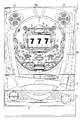
パチンコ遊技機1は、縦長の方形状に形成された外枠(図示せず)と、外枠の内側に開閉可能に取り付けられた遊技枠とで構成される。また、パチンコ遊技機1は、遊技枠に開閉可能に設けられている額縁状に形成されたガラス扉枠2を有する。遊技枠は、外枠に対して開閉自在に設置される前面枠(図示せず)と、機構部品等が取り付けられる機構板と、それらに取り付けられる種々の部品(後述する遊技盤を除く。)とを含む構造体である。
The
図1に示すように、パチンコ遊技機1は、額縁状に形成されたガラス扉枠2を有する。ガラス扉枠2の下部表面には打球供給皿(上皿)3がある。打球供給皿3の下部には、打球供給皿3に収容しきれない遊技球を貯留する余剰球受皿4と遊技球を発射する打球操作ハンドル(操作ノブ)5が設けられている。ガラス扉枠2の背面には、遊技盤6が着脱可能に取り付けられている。なお、遊技盤6は、それを構成する板状体と、その板状体に取り付けられた種々の部品とを含む構造体である。また、遊技盤6の前面には遊技領域7が形成されている。
As shown in FIG. 1, the
遊技領域7の中央付近には、それぞれが識別情報としての図柄を可変表示する複数の可変表示部を含む画像表示手段としての可変表示装置(特別図柄表示装置)9が設けられている。可変表示装置9には、例えば「左」、「中」、「右」の3つの可変表示部(図柄表示エリア)がある。また、可変表示装置9には、始動入賞口14に入った有効入賞球数すなわち始動記憶数を表示する4つの特別図柄始動記憶表示エリア(始動記憶表示エリア)18が設けられている。有効始動入賞がある毎に、表示色が変化する(例えば青色表示から赤色表示に変化)始動記憶表示エリアを1増やす。そして、可変表示装置9の可変表示が開始される毎に、表示色が変化している始動記憶数表示エリアを1減らす(すなわち表示色をもとに戻す)。この例では、図柄表示エリアと始動記憶表示エリアとが区分けされて設けられているので、可変表示中も始動記憶数が表示された状態にすることができる。なお、始動記憶表示エリアを図柄表示エリアの一部に設けるようにしてもよい。また、可変表示中は始動記憶数の表示を中断するようにしてもよい。また、この例では、始動記憶表示エリアが可変表示装置9に設けられているが、始動記憶数を表示する表示器(特別図柄始動記憶表示器)を可変表示装置9とは別個に設けてもよい。
Near the center of the
可変表示装置9の下方には、始動入賞口14としての可変入賞球装置15が設けられている。始動入賞口14に入った入賞球は、遊技盤6の背面に導かれ、始動口スイッチ14aによって検出される。また、始動入賞口14の下部には開閉動作を行う可変入賞球装置15が設けられている。可変入賞球装置15は、ソレノイド16によって開状態とされる。
Below the
可変入賞球装置15の下部には、特定遊技状態(大当り状態)においてソレノイド21によって開状態とされる開閉板20が設けられている。開閉板20は大入賞口(可変入賞球装置)を開閉する手段である。開閉板20から遊技盤6の背面に導かれた入賞球のうち一方(V入賞領域:特別領域)に入った入賞球はVカウントスイッチ22で検出され、開閉板20からの入賞球はカウントスイッチ23で検出される。遊技盤6の背面には、大入賞口内の経路を切り換えるためのソレノイド21Aも設けられている。
An open /
ゲート32に遊技球が入賞しゲートスイッチ32aで検出されると、普通図柄表示器10の表示の可変表示が開始される。この実施の形態では、左右のランプ(点灯時に図柄が視認可能になる)が交互に点灯することによって可変表示が行われ、例えば、可変表示の終了時に右側のランプが点灯すれば当たりとなる。そして、普通図柄表示器10における停止図柄が所定の図柄(当り図柄)である場合に、可変入賞球装置15が所定回数、所定時間だけ開状態になる。普通図柄表示器10の近傍には、ゲート32に入った入賞球数を表示する4つのLEDによる表示部を有する普通図柄始動記憶表示器41が設けられている。ゲート32への入賞がある毎に、普通図柄始動記憶表示器41は点灯するLEDを1増やす。そして、普通図柄表示器10の可変表示が開始される毎に、点灯するLEDを1減らす。
When a game ball wins the
遊技盤6には、複数の入賞口29,30,33,39が設けられ、遊技球の入賞口29,30,33,39への入賞は、それぞれ入賞口スイッチ29a,30a,33a,39aによって検出される。各入賞口29,30,33,39は、遊技媒体を受け入れて入賞を許容する領域として遊技盤6に設けられる入賞領域を構成している。なお、始動入賞口14や大入賞口も、遊技媒体を受け入れて入賞を許容する入賞領域を構成する。遊技領域7の左右周辺には、遊技中に点滅表示される装飾ランプ25が設けられ、下部には、入賞しなかった遊技球を吸収するアウト口26がある。また、遊技領域7の外側の左右上部には、効果音を発する2つのスピーカ27が設けられている。遊技領域7の外周には、天枠ランプ28a、左枠ランプ28bおよび右枠ランプ28cが設けられている。さらに、遊技領域7における各構造物(大入賞口等)の周囲には装飾LEDが設置されている。天枠ランプ28a、左枠ランプ28bおよび右枠ランプ28cおよび装飾用LEDは、遊技機に設けられている装飾発光体の一例である。
The
そして、この例では、左枠ランプ28bの近傍に、賞球払出中に点灯する賞球LED51が設けられ、天枠ランプ28aの近傍に、補給球が切れたときに点灯する球切れLED52が設けられている。上記のように、この実施の形態のパチンコ遊技機1には、発光体としてのランプやLEDが各所に設けられている。さらに、プリペイドカードが挿入されることによって球貸しを可能にするプリペイドカードユニットが、パチンコ遊技機1に隣接して設置されることもある(図示せず)。
In this example, a prize ball LED 51 that is lit while paying out a prize ball is provided in the vicinity of the
打球発射装置から発射された遊技球は、打球レールを通って遊技領域7に入り、その後、遊技領域7を下りてくる。遊技球が始動入賞口14に入り始動口スイッチ14aで検出されると、図柄の可変表示を開始できる状態であれば、可変表示装置9において特別図柄が可変表示(変動)を始める。図柄の可変表示を開始できる状態でなければ、始動記憶数を1増やす。
The game balls launched from the hit ball launching device enter the
可変表示装置9における特別図柄の可変表示は、一定時間が経過したときに停止する。停止時の特別図柄の組み合わせが大当り図柄(特定表示結果)であると、大当り遊技状態に移行する。すなわち、開閉板20が、一定時間経過するまで、または、所定個数(例えば10個)の遊技球が入賞するまで開放する。そして、開閉板20の開放中に遊技球がV入賞領域に入賞しVカウントスイッチ22で検出されると、継続権が発生し開閉板20の開放が再度行われる。継続権の発生は、所定回数(例えば15ラウンド)許容される。
The variable display of the special symbol on the
停止時の可変表示装置9における特別図柄の組み合わせが確率変動を伴う大当り図柄(確変図柄)の組み合わせである場合には、次に大当りとなる確率が高くなる。すなわち、確変状態という遊技者にとってさらに有利な状態となる。
When the combination of special symbols in the
遊技球がゲート32に入賞すると、普通図柄表示器10において普通図柄が可変表示される状態になる。また、普通図柄表示器10における停止図柄が所定の図柄(当り図柄)である場合に、可変入賞球装置15が所定時間だけ開状態になる。さらに、確変状態では、普通図柄表示器10における停止図柄が当り図柄になる確率が高められるとともに、可変入賞球装置15の開放時間と開放回数が高められる。すなわち、可変入賞球装置15の開放時間と開放回数は、普通図柄の停止図柄が当り図柄であったり、特別図柄の停止図柄が確変図柄である場合等に高められ、遊技者にとって不利な状態から有利な状態に変化する。なお、開放回数が高められることは、閉状態から開状態になることも含む概念である。
When the game ball wins the
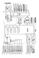
図2は、遊技機に設けられている(具体的には遊技機裏面に設置されている)基板であって、遊技制御用マイクロコンピュータ等が搭載された遊技制御基板(主基板)31における回路構成の一例を示すブロック図である。なお、図2には、遊技機に搭載されている払出制御基板37、ランプドライバ基板35、音声出力基板70および演出制御基板80も示されている。主基板31には、プログラムに従ってパチンコ遊技機1を制御する基本回路(遊技制御用マイクロコンピュータに相当:遊技制御手段)53と、ゲートスイッチ32a、始動口スイッチ14a、V入賞スイッチ22、カウントスイッチ23、入賞口スイッチ29a,30a,33a,39aおよびクリアスイッチ921からの信号を基本回路53に与えるスイッチ回路58と、可変入賞球装置15を開閉するソレノイド16、開閉板20を開閉するソレノイド21および大入賞口内の経路を切り換えるためのソレノイド21Aを基本回路53からの指令に従って駆動するソレノイド回路59とが搭載されている。クリアスイッチ921は、例えば遊技機に設置されている電源基板に搭載されている。
FIG. 2 shows a circuit in a game control board (main board) 31 provided on a gaming machine (specifically, installed on the back of the gaming machine) on which a game control microcomputer or the like is mounted. It is a block diagram which shows an example of a structure. 2 also shows a payout control board 37, a
なお、図2には示されていないが、カウントスイッチ短絡信号もスイッチ回路58を介して基本回路53に伝達される。また、ゲートスイッチ32a、始動口スイッチ14a、V入賞スイッチ22、カウントスイッチ23、入賞口スイッチ29a,30a,33a,39a等のスイッチは、センサと称されているものでもよい。すなわち、遊技球を検出できる遊技媒体検出手段(この例では遊技球検出手段)であれば、その名称を問わない。
Although not shown in FIG. 2, the count switch short circuit signal is also transmitted to the
また、基本回路53から与えられるデータに従って、大当りの発生を示す大当り情報、可変表示装置9における図柄の可変表示開始に利用された始動入賞球の個数を示す有効始動情報、確率変動が生じたことを示す確変情報等の情報出力信号を、遊技機裏面に設置されている情報端子盤を介してホールコンピュータ等の外部装置に対して出力する情報出力回路64が搭載されている。さらに、電力供給が開始されたときにCPU56にリセット信号を与えるシステムリセット回路65が搭載されている。
Further, according to the data given from the
遊技制御用マイクロコンピュータで実現される基本回路53は、ゲーム制御(遊技進行制御)用のプログラム等を記憶するROM54、ワークメモリとして使用される記憶手段(変動データを記憶する変動データ記憶手段)としてのRAM55、プログラムに従って制御動作を行うCPU56およびI/Oポート部57を含む。この実施の形態では、ROM54およびRAM55はCPU56に内蔵されている。すなわち、CPU56は、1チップマイクロコンピュータである。1チップマイクロコンピュータは、少なくともRAM55が内蔵されていればよく、ROM54およびI/Oポート部57は外付けであっても内蔵されていてもよい。なお、CPU56はROM54に格納されているプログラムに従って制御を実行するので、以下、CPU56が実行する(または、処理を行う)ということは、具体的には、CPU56がプログラムに従って制御を実行することである。このことは、主基板31以外の他の基板に搭載されているCPUについても同様である。また、遊技制御手段は、遊技制御用マイクロコンピュータで実現される基本回路53で実現されているが、主として、遊技制御用マイクロコンピュータにおけるプログラムに従って制御を実行するCPU56で実現される。
A
また、RAM55は、その一部または全部がバックアップ電源によってバックアップされている不揮発性記憶手段としてのバックアップRAMである。すなわち、遊技機に対する電力供給が停止しても、所定期間(バックアップ電源が電力供給不能になるまで)は、RAM55の一部または全部の内容は保存される。特に、少なくとも、遊技状態すなわち遊技制御手段の制御状態に応じたデータ(特別図柄プロセスフラグ等)と未払出賞球数を示すデータは、バックアップRAMに保存される。なお、遊技制御手段の制御状態に応じたデータとは、停電等が生じた後に復旧した場合に、そのデータにもとづいて、制御状態を停電等の発生前に復旧させるために必要なデータである。なお、この実施の形態では、RAM55の全部が、電源バックアップされているとする。
The
この実施の形態では、演出制御基板80に搭載されている演出制御用マイクロコンピュータで実現される演出制御手段が、遊技盤に設けられている普通図柄保留記憶表示器41および飾りランプ25等の表示制御を行うとともに、枠側に設けられている天枠ランプ28a、左枠ランプ28b、右枠ランプ28c、賞球ランプ51および球切れランプ52の表示制御を行う。なお、各ランプはLEDその他の種類の発光体でもよい。すなわち、ランプやLEDは発光体の一例であり、以下、ランプ・LEDと総称することがある。また、可変表示装置9の上部および左右部には、可変表示装置飾りLED(センター飾りLED)が設置され、大入賞口の内部には大入賞口内飾りLEDが設置され、大入賞口の左右には、大入賞口左飾りLEDおよび大入賞口右飾りLEDが設置されている。演出制御手段は、それらの発光体の制御も行う。
In this embodiment, the effect control means realized by the effect control microcomputer mounted on the
なお、ランプ・LEDを駆動するための駆動信号は、ランプドライバ基板35において作成される。また、特別図柄を可変表示する可変表示装置9および普通図柄を可変表示する普通図柄表示器10の表示制御は、演出制御基板80に搭載されている演出制御手段によって行われる。
A drive signal for driving the lamp / LED is generated in the
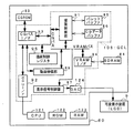
図3は、演出制御基板80、ランプドライバ基板35および音声出力基板70の回路構成例を示すブロック図である。演出制御基板80において、演出制御用CPU101は、ROM(図示せず)に格納されたプログラムに従って動作し、主基板31からのストローブ信号(演出制御INT信号)に応じて、入力ドライバ102および入力ポート103を介して演出制御コマンドを受信する。演出制御用CPU101は、演出制御コマンドにもとづいて、GCL(グラフィックコントローラLSI)106に、LCDを用いた可変表示装置9の表示制御を行わせる。GCL106は、VDP(ビデオディスプレイプロセッサ)と呼ばれることもある。さらに、演出制御用CPU101は、出力ポート104およびランプ駆動回路107を介して普通図柄表示器10の表示制御を行う。なお、演出制御用マイクロコンピュータは、演出制御用CPU101、ROM、RAMおよびI/Oポートを含む。
FIG. 3 is a block diagram illustrating a circuit configuration example of the
さらに、演出制御用CPU101は、出力ポート104および出力ドライバ110を介して音声出力基板70に対して音番号データを出力する。また、演出制御用CPU101に入出力するバス(アドレスバス、データバス、および書込/読出信号等の制御信号ラインを含む)はバスドライバ105を介してランプドライバ基板35まで延長されている。
Further, the
ランプドライバ基板35において、演出制御用CPU101に入出力するバスは、バスレシーバ351を介して出力ポート352および拡張ポート353に接続される。出力ポート352から出力される各ランプを駆動する信号は、ランプドライバ354で増幅され各ランプに供給される。また、出力ポート352から出力される各LEDを駆動する信号は、LED駆動回路355で増幅され各LEDに供給される。
In the
この実施の形態では、遊技機に設けられているランプ・LEDは、演出制御基板80に搭載されている演出用CPU101を含む演出制御手段によって制御される。また、可変表示装置9、普通図柄表示器10およびランプ・LED等を制御するためのデータがROMに格納されている。演出用CPU101は、ROMに格納されているデータにもとづいて可変表示装置9、普通図柄表示器10およびランプ・LED等を制御する。そして、ランプドライバ基板35に搭載されている出力ポート352および各駆動回路を介して、ランプ・LEDが駆動される。従って、機種変更を行う場合に、演出制御基板80を新たな機種のものに交換すれば、ランプドライバ基板35を交換せずに機種変更を実現することができる。
In this embodiment, the lamps / LEDs provided in the gaming machine are controlled by effect control means including an
なお、演出制御基板80、ランプドライバ基板35および音声出力基板70は独立した基板であるが、それらは、例えば、遊技機裏面において、1つのボックスに収容された状態で設置される。また、拡張ポート353は、機種変更を行う場合に、ランプ・LED等の数が増加した場合を考慮して設置されるが、設置されていなくてもよい。
The
音声出力基板70において、演出制御基板80からの音番号データは、入力ドライバ702を介して、例えばデジタルシグナルプロセッサによる音声合成用IC703に入力される。音声合成用IC703は、音番号データに応じたデータを音声データROM704から読み出し、読み出したデータに応じた音声や効果音を発生し増幅回路705に出力する。増幅回路705は、音声合成用IC703の出力レベルを、ボリューム706で設定されている音量に応じたレベルに増幅した音声信号をスピーカ27に出力する。
In the
音声データROM704に格納されている音番号データに応じたデータは、所定期間(例えば特別図柄の変動時間)における効果音または音声の出力態様を時系列的に示すデータの集まりである。音声合成用IC703は、音番号データを入力すると、音声データROM704内の対応するデータに従って音出力制御を行う。対応するデータに従った音出力制御は、次の音番号データを入力するまで継続される。そして、音声合成用IC703は、次の音番号データを入力すると、新た入力した音番号データに対応した音声データROM704内のデータに従って音出力制御を行う。
The data corresponding to the sound number data stored in the
この実施の形態では、スピーカ27から出力される音声や効果音は演出制御手段によって制御されるのであるが、演出制御手段は、音声出力基板70に音番号データを出力する。音声出力基板70において、音声データROM704には、遊技の進行に伴って出現しうる音声や効果音を実現するための多数のデータが格納され、それらのデータは音番号データに対応付けられている。従って、演出制御手段は、音番号データを出力するだけで音出力制御を実現することができる。なお、音番号データは例えば1バイトデータであり、シリアル信号線またはパラレル信号線によって音声出力基板70に転送される。
In this embodiment, the sound and sound effect output from the
なお、この実施の形態では、1つの演出制御手段が、可変表示の表示制御、ランプ・LED(発光体)の点灯制御およびスピーカ27からの音発生制御を実行しているが、すなわち、演出制御手段が、表示制御手段、発光体制御手段および音制御手段を実現している。よって、可変表示装置9による表示演出、ランプ・LEDを用いた演出、および音による演出を容易に同期させることができる。しかし、演出制御手段の負担を軽くするために、発光体制御用マイクロコンピュータや音制御用マイクロコンピュータを設け、それらが、遊技制御手段または演出制御手段(この場合には表示制御手段となる。)からの指令に応じて、発光体制御および音制御を行うように構成してもよい。
In this embodiment, one effect control means executes display control of variable display, lighting control of lamps / LEDs (light emitters), and sound generation control from the
図4は、演出制御基板80における画像表示制御に関わる部分の回路構成例を示すブロック図である。演出制御基板80には、演出制御用CPU101とともに、演出制御用のプログラムや図柄表示・発光・音声出力等の各種の演出パターン等を記憶するROM122と、ワークメモリとして使用されるRAM123とが搭載されている。なお、ROM121およびRAM123は、演出制御用CPU101に内蔵されていてもよい。
FIG. 4 is a block diagram illustrating a circuit configuration example of a portion related to image display control in the
可変表示装置9の表示制御を実行する際に、演出制御用CPU101は、演出制御コマンドに応じた指示をGCL106に与える。GCL106は、CGROM83等から必要なデータを読み出す。なお、CGROM83には、図柄(特別図柄)や使用頻度の高いキャラクタの画像データが格納されている。よって、CGROM83は、キャラクタROMと呼ばれることもある。CGROM83に格納されている使用頻度の高いキャラクタとは、例えば、可変表示装置9に表示される人物、動物、または、文字、図形もしくは記号等からなる画像である。なお、キャラクタには、実写による動画像(映像)や静止画像も含まれる。また、CGROM83に格納されている画像データを画像要素データということがある。
When executing the display control of the
GCL106は、入力したデータに従って可変表示装置9に表示するための画像データを生成し、R(赤),G(緑),B(青)信号および同期信号を可変表示装置9に出力する。可変表示装置9は、例えば、多数の画素(ピクセル)を用いたドットマトリクス方式による画面表示を行う。この実施の形態では、R,G,B信号がそれぞれ8ビットで表される。したがって、可変表示装置9は、GCL106からの指示に従って、R,G,Bそれぞれが256階調であり、約1670万色の多色表示を行うことができる。なお、R,G,B信号のビット数は8ビット以外のビット数であってもよく、また、R,G,B信号の各ビット数が互いに異なる数であってもよい。
The
演出制御基板80には、CGROM83の他に、SDRAM(シンクロナスDRAM)84等の各種の記憶媒体が備えられている。また、SDRAM84にはフレームバッファの領域が確保される。また、キャラクタのソースデータ、表示色の特定や変更等のために用いられるパレットデータ等の表示画像に関するデータが格納される。ソースデータは画像データであり、元画像のデータという意味で、ソースデータと表現される。さらに、SDRAM84には、VRAM(ビデオRAM)として使用される領域も確保される。
The
GCL106は、所定のパレットデータを一時的に保存するためなどに用いられるパレットデータバッファ85や、所定のCGデータを一時的に保存するためなどに用いられるCGデータバッファ86等の各種の記憶媒体の他、描画制御部91と、可変表示装置9に信号を出力するための表示信号制御部87と、動画圧縮処理や伸張処理を行う動画圧縮伸張部89とを含む。表示信号制御部87は、画像データをDAC(D−A変換回路)104に出力する。DAC104は、画像合成用IC132からの画像データをアナログ信号として可変表示装置9としてのLCDに出力する。描画制御部91は、例えば、アトリビュート解析部、VRAMアドレス生成部、クリッピング部および半透明輝度変調部を含む。アトリビュート解析部は、キャラクタを描画する際に使用されるパラメータの解析を行う。パラメータには、画像の描画順序、色数、拡大縮小率、パレット番号、座標等を指定するための情報が設定されている。なお、動画圧縮伸張部89は、GCL106によって制御されるように構成しても、演出制御用CPU101によって制御されるように構成してもよい。
The
GCL106の内部には、CGバスとVRAMバスとが設けられている。CGROM83とCGバスとの間には、CGバスインタフェース(CGバスI/F)93が設置されている。CGバスにはCPUI/F92も接続され、演出制御用CPU101は、CPUI/F92を介して、CGバスに接続されている部分をアクセスすることができる。具体的には、演出制御用CPU101は、CGバスに接続されている描画制御レジスタ95をアクセスする。描画制御レジスタ95には、描画制御部91に対する演出制御用CPU101からの指示等のデータが格納される。従って、演出制御用CPU101は、GCL106に対する指示を描画制御レジスタ95に書き込み、GCL106は、演出制御用CPU101からの指示を描画制御レジスタ95を介して受け取る。また、SDRAM84とVRAMバスとの間にはVRAMI/F94が設置されている。なお、動画伸張部89は、VRAMバスを介してVRAM84をアクセスできるとともに、CGバスを介して描画制御レジスタ95をアクセスすることができる。
Inside the
GCL106は、演出制御用CPU101の指示に応じて、CGROM83から図柄およびキャラクタのソースデータを読み出して、VRAMに格納する。さらに、VRAMに展開された画像データをSDRAM84に確保されている領域であるフレームバッファに格納する。表示信号制御部87は、フレームバッファに格納されている画像データをDAC124を介して可変表示装置9に出力する。「VRAMに展開」とは、VRAMに書き込むこと、すなわちVRAMに記憶させることを意味する。
The
なお、図3では、ROM121、RAM123、CGROM83、およびSDRAM84は、記載省略されている。そして、図4では、出力ポート104は記載省略されている。
In FIG. 3, the ROM 121, RAM 123,
次に遊技機の動作について説明する。図5は、主基板31における遊技制御手段(CPU56およびROM,RAM等の周辺回路)が実行するメイン処理を示すフローチャートである。遊技機に対して電源が投入され、リセット信号が入力されるリセット端子の入力レベルがハイレベルになると、CPU56は、プログラムの内容が正当か否かを確認するための処理であるセキュリティチェック処理を実行した後、ステップS1以降のメイン処理を開始する。メイン処理において、CPU56は、まず、必要な初期設定を行う。 Next, the operation of the gaming machine will be described. FIG. 5 is a flowchart showing main processing executed by the game control means (CPU 56 and peripheral circuits such as ROM and RAM) on the main board 31. When the gaming machine is turned on and the input level of the reset terminal to which a reset signal is input becomes high, the CPU 56 performs a security check process that is a process for confirming whether the contents of the program are valid. After execution, the main processing after step S1 is started. In the main process, the CPU 56 first performs necessary initial settings.
初期設定処理において、CPU56は、まず、割込禁止に設定する(ステップS1)。次に、割込モードを割込モード2に設定し(ステップS2)、スタックポインタにスタックポインタ指定アドレスを設定する(ステップS3)。そして、内蔵デバイスレジスタの初期化を行う(ステップS4)。また、内蔵デバイス(内蔵周辺回路)であるCTC(カウンタ/タイマ)およびPIO(パラレル入出力ポート)の初期化(ステップS5)を行った後、RAMをアクセス可能状態に設定する(ステップS6)。なお、割込みモード2は、遊技制御用マイクロコンピュータ56が内蔵する特定レジスタ(Iレジスタ)の値(1バイト)と内蔵デバイスが出力する割込みベクタ(1バイト:最下位ビット0)から合成されるアドレスが、割込み番地を示すモードである。
In the initial setting process, the CPU 56 first sets the interrupt prohibition (step S1). Next, the interrupt mode is set to interrupt mode 2 (step S2), and a stack pointer designation address is set to the stack pointer (step S3). Then, the built-in device register is initialized (step S4). Further, after initialization (step S5) of CTC (counter / timer) and PIO (parallel input / output port) which are built-in devices (built-in peripheral circuits), the RAM is set in an accessible state (step S6). The interrupt
次いで、CPU56は、入力ポートを介して入力されるクリアスイッチ921の出力信号の状態を1回だけ確認する(ステップS7)。その確認においてオンを検出した場合には、CPU56は、通常の初期化処理を実行する(ステップS11〜ステップS14)。
Next, the CPU 56 checks the state of the output signal of the
クリアスイッチ921がオンの状態でない場合には、遊技機への電力供給が停止したときにバックアップRAM領域のデータ保護処理(例えばパリティデータの付加等の電力供給停止時処理)が行われたか否か確認する(ステップS8)。そのような保護処理が行われていないことを確認したら、CPU56は初期化処理を実行する。バックアップRAM領域にバックアップデータがあるか否かは、例えば、電力供給停止時処理においてバックアップRAM領域に設定されるバックアップフラグの状態によって確認される。この例では、バックアップフラグ領域に「55H」が設定されていればバックアップあり(オン状態)を意味し、「55H」以外の値が設定されていればバックアップなし(オフ状態)を意味する。
If the
バックアップありを確認したら、CPU56は、バックアップRAM領域のデータチェック(この例ではパリティチェック)を行う(ステップS9)。ステップS9では、算出したチェックサムと、電力供給停止時処理で同一の処理によって算出され保存されているチェックサムとを比較する。不測の停電等の電力供給停止が生じた後に復旧した場合には、バックアップRAM領域のデータは保存されているはずであるから、チェック結果(比較結果)は正常(一致)になる。チェック結果が正常でないということは、バックアップRAM領域のデータが、電力供給停止時のデータとは異なっていることを意味する。そのような場合には、内部状態を電力供給停止時の状態に戻すことができないので、電力供給の停止からの復旧時でない電源投入時に実行される初期化処理を実行する。 After confirming that there is a backup, the CPU 56 performs a data check of the backup RAM area (parity check in this example) (step S9). In step S9, the calculated checksum is compared with the checksum calculated and stored by the same process in the power supply stop process. When the power supply is stopped after an unexpected power failure or the like, the data in the backup RAM area should be saved, so the check result (comparison result) is normal (matched). That the check result is not normal means that the data in the backup RAM area is different from the data when the power supply is stopped. In such a case, since the internal state cannot be returned to the state when the power supply is stopped, an initialization process that is executed when the power is turned on is not performed when the power supply is stopped.
チェック結果が正常であれば、CPU56は、遊技制御手段の内部状態と演出制御手段等の電気部品制御手段の制御状態を電力供給停止時の状態に戻すための遊技状態復旧処理を行う(ステップS10)。そして、バックアップRAM領域に保存されていたPC(プログラムカウンタ)の退避値がPCに設定され、そのアドレスに復帰する。 If the check result is normal, the CPU 56 performs a game state restoration process for returning the internal state of the game control means and the control state of the electric component control means such as the effect control means to the state when the power supply is stopped (step S10). ). Then, the saved value of the PC (program counter) stored in the backup RAM area is set in the PC, and the address is restored.
なお、この実施の形態では、バックアップフラグとチェックデータとの双方を用いてバックアップRAM領域のデータが保存されているか否かを確認しているが、いずれか一方のみを用いてもよい。すなわち、バックアップフラグとチェックデータとのいずれかを、状態復旧処理を実行するための契機としてもよい。 In this embodiment, it is confirmed whether or not the data in the backup RAM area is stored by using both the backup flag and the check data, but only one of them may be used. That is, either the backup flag or the check data may be used as an opportunity for executing the state recovery process.
初期化処理では、CPU56は、まず、RAMクリア処理を行う(ステップS11)。また、所定の作業領域(例えば、普通図柄判定用乱数カウンタ、普通図柄判定用バッファ、特別図柄左中右図柄バッファ、特別図柄プロセスフラグ、払出コマンド格納ポインタ、賞球中フラグ、球切れフラグ、払出停止フラグなど制御状態に応じて選択的に処理を行うためのフラグ)に初期値を設定する作業領域設定処理を行う(ステップS12)。さらに、サブ基板(この実施の形態では払出制御基板35および演出制御基板80)を初期化するための初期化コマンドを各サブ基板に送信する処理を実行する(ステップS13)。初期化コマンドとして、可変表示装置9に表示される初期図柄を示すコマンド(演出制御基板80に対して)や賞球ランプ51および球切れランプ52の消灯を指示するコマンド等がある。
In the initialization process, the CPU 56 first performs a RAM clear process (step S11). In addition, a predetermined work area (for example, a normal symbol determination random number counter, a normal symbol determination buffer, a special symbol left middle right symbol buffer, a special symbol process flag, a payout command storage pointer, a winning ball flag, a ball out flag, a payout A work area setting process for setting an initial value to a flag such as a stop flag for selectively performing processing according to the control state is performed (step S12). Further, a process of transmitting an initialization command for initializing the sub-boards (the
そして、2ms毎に定期的にタイマ割込がかかるようにCPU56に設けられているCTCのレジスタの設定が行われる(ステップS14)。すなわち、初期値として2msに相当する値が所定のレジスタ(時間定数レジスタ)に設定される。 Then, a CTC register set in the CPU 56 is set so that a timer interrupt is periodically generated every 2 ms (step S14). That is, a value corresponding to 2 ms is set in a predetermined register (time constant register) as an initial value.
初期化処理の実行(ステップS11〜S14)が完了すると、メイン処理で、表示用乱数更新処理(ステップS17)および初期値用乱数更新処理(ステップS18)が繰り返し実行される。表示用乱数更新処理および初期値用乱数更新処理が実行されるときには割込禁止状態とされ(ステップS16)、表示用乱数更新処理および初期値用乱数更新処理の実行が終了すると割込許可状態とされる(ステップS19)。表示用乱数とは、可変表示装置9に表示される図柄を決定するための乱数であり、表示用乱数更新処理とは、表示用乱数を発生するためのカウンタのカウント値を更新する処理である。また、初期値用乱数更新処理とは、初期値用乱数を発生するためのカウンタのカウント値を更新する処理である。初期値用乱数とは、大当りとするか否かを決定するための乱数を発生するためのカウンタ(大当り判定用乱数発生カウンタ)等の、カウント値の初期値を決定するための乱数である。後述する遊技の進行を制御する遊技制御処理(遊技制御用マイクロコンピュータが、遊技機に設けられている可変表示装置9、可変入賞球装置、球払出装置等の遊技用の装置を、自身で制御する処理、または他のマイクロコンピュータに制御させるために指令信号を送信する処理、遊技装置制御処理ともいう)において、大当り決定用乱数発生カウンタのカウント値が1周すると、そのカウンタに初期値が設定される。
When the execution of the initialization process (steps S11 to S14) is completed, the display random number update process (step S17) and the initial value random number update process (step S18) are repeatedly executed in the main process. When the display random number update process and the initial value random number update process are executed, the interrupt disabled state is set (step S16). When the display random number update process and the initial value random number update process are finished, the interrupt enabled state is set. (Step S19). The display random number is a random number for determining a symbol displayed on the
なお、表示用乱数更新処理が実行されるときには割込禁止状態とされるのは、表示用乱数更新処理が後述するタイマ割込処理でも実行されることから、タイマ割込処理における処理と競合してしまうのを避けるためである。すなわち、ステップS17の処理中にタイマ割込が発生してタイマ割込処理中で表示用乱数を発生するためのカウンタのカウント値を更新してしまったのでは、カウント値の連続性が損なわれる場合がある。しかし、ステップS17の処理中では割込禁止状態にしておけば、そのような不都合が生ずることはない。 Note that when the display random number update process is executed, the interrupt is prohibited. The display random number update process is also executed in the timer interrupt process described later, and thus conflicts with the process in the timer interrupt process. This is to avoid that. That is, if the timer interrupt is generated during the process of step S17 and the counter value for generating the display random number is updated during the timer interrupt process, the continuity of the count value is impaired. There is a case. However, such an inconvenience does not occur if the interrupt is prohibited during the process of step S17.
タイマ割込が発生すると、CPU56は、図6に示すステップS20〜S33の遊技制御処理を実行する。遊技制御処理において、CPU56は、まず、電源断信号が出力されたか否か(オン状態になったか否か)を検出する電源断検出処理を実行する(ステップS20)。電源断信号は、例えば電源基板に搭載されている電圧低下監視回路が、遊技機に供給される電源の電圧の低下を検出した場合に出力する。そして、電源断検出処理において、CPU56は、電源断信号が出力されたことを検出したら、必要なデータをバックアップRAM領域に保存するための電力供給停止時処理を実行する。次いで、スイッチ回路58を介して、ゲートスイッチ32a、始動口スイッチ14a、カウントスイッチ23および入賞口スイッチ24a等のスイッチの検出信号を入力し、それらの状態判定を行う(スイッチ処理:ステップS21)。
When the timer interruption occurs, the CPU 56 executes the game control process of steps S20 to S33 shown in FIG. In the game control process, the CPU 56 first executes a power-off detection process for detecting whether or not a power-off signal has been output (whether the power-off signal has been turned on) (step S20). The power-off signal is output when, for example, a voltage drop monitoring circuit mounted on the power supply board detects a drop in the voltage of the power supplied to the gaming machine. In the power-off detection process, when detecting that the power-off signal has been output, the CPU 56 executes a power supply stop process for saving necessary data in the backup RAM area. Next, detection signals of switches such as the
次に、遊技制御に用いられる大当り判定用の乱数等の各判定用乱数を生成するための各カウンタのカウント値を更新する処理を行う(ステップS22)。CPU56は、さらに、初期値用乱数を生成するためのカウンタのカウント値を更新する処理および表示用乱数を生成するためのカウンタのカウント値を更新する処理を行う(ステップS23,S24)。 Next, a process of updating the count value of each counter for generating each determination random number such as a big hit determination random number used for game control is performed (step S22). The CPU 56 further performs processing for updating the count value of the counter for generating the initial value random number and processing for updating the count value of the counter for generating the display random number (steps S23 and S24).
さらに、CPU56は、特別図柄プロセス処理を行う(ステップS25)。特別図柄プロセス制御では、遊技状態に応じてパチンコ遊技機1を所定の順序で制御するための特別図柄プロセスフラグに従って該当する処理が選び出されて実行される。そして、特別図柄プロセスフラグの値は、遊技状態に応じて各処理中に更新される。また、普通図柄プロセス処理を行う(ステップS26)。普通図柄プロセス処理では、普通図柄表示器10の表示状態を所定の順序で制御するための普通図柄プロセスフラグに従って該当する処理が選び出されて実行される。そして、普通図柄プロセスフラグの値は、遊技状態に応じて各処理中に更新される。
Further, the CPU 56 performs special symbol process processing (step S25). In the special symbol process control, corresponding processing is selected and executed according to a special symbol process flag for controlling the
次いで、CPU56は、特別図柄に関する演出制御コマンドをRAM55の所定の領域に設定して演出制御コマンドを送出する処理を行う(特別図柄コマンド制御処理:ステップS27)。また、普通図柄に関する演出制御コマンドをRAM55の所定の領域に設定して演出制御コマンドを送出する処理を行う(普通図柄コマンド制御処理:ステップS28)。
Next, the CPU 56 performs a process of setting an effect control command related to the special symbol in a predetermined area of the
さらに、CPU56は、例えばホール管理用コンピュータに供給される大当り情報、始動情報、確率変動情報などのデータを出力する情報出力処理を行う(ステップS29)。 Further, the CPU 56 performs information output processing for outputting data such as jackpot information, start information, probability variation information supplied to the hall management computer, for example (step S29).
また、CPU56は、入賞口スイッチ29a,30a,33a,39aの検出信号にもとづく賞球個数の設定などを行う賞球処理を実行する(ステップS30)。具体的には、入賞口スイッチ29a,30a,33a,39aの何れかがオンしたことにもとづく入賞検出に応じて、払出制御基板37に賞球個数を示す払出制御コマンドを出力する。払出制御基板37に搭載されている払出制御用CPUは、賞球個数を示す払出制御コマンドに応じて球払出装置97を駆動する。
In addition, the CPU 56 executes a prize ball process for setting the number of prize balls based on the detection signals of the
そして、CPU56は、保留記憶数の増減をチェックする記憶処理を実行する(ステップS31)。また、遊技機の制御状態を遊技機外部で確認できるようにするための試験信号を出力する処理である試験端子処理を実行する(ステップS32)。さらに、所定の条件が成立したときにソレノイド回路59に駆動指令を出力する出力処理を行う(ステップS33)。ソレノイド回路59は、遊技制御手段からの駆動指令に応じて、可変入賞球装置15または開閉板20を開状態または閉状態としたり、大入賞口内の遊技球通路を切り替えたりするために、駆動指令に応じてソレノイド16,21,21Aを駆動する。その後、CPU56は、制御状態を割込許可状態に設定する(ステップS34)。
And CPU56 performs the memory | storage process which checks the increase / decrease in a pending | holding memory | storage number (step S31). In addition, a test terminal process, which is a process for outputting a test signal for enabling the control state of the gaming machine to be confirmed outside the gaming machine, is executed (step S32). Further, an output process for outputting a drive command to the
以上の制御によって、この実施の形態では、遊技制御処理は2ms毎に起動されることになる。なお、この実施の形態では、タイマ割込処理で遊技制御処理が実行されているが、タイマ割込処理では例えば割込が発生したことを示すフラグのセットのみがなされ、遊技制御処理はメイン処理において実行されるようにしてもよい。 With the above control, in this embodiment, the game control process is started every 2 ms. In this embodiment, the game control process is executed by the timer interrupt process. However, in the timer interrupt process, for example, only a flag indicating that an interrupt has occurred is set, and the game control process is performed by the main process. May be executed.
図7は、CPU56が実行する特別図柄プロセス処理のプログラムの一例を示すフローチャートである。図7に示す特別図柄プロセス処理は、図5のフローチャートにおけるステップS25の具体的な処理である。CPU56は、特別図柄プロセス処理を行う際に、変動短縮タイマ減算処理(ステップS310)を行い、遊技盤6に設けられている始動入賞口14に遊技球が入賞したことを検出するための始動口スイッチ14aがオンしていたら、すなわち遊技球が始動入賞口14に入賞する始動入賞が発生していたら(ステップS311)、始動口スイッチ通過処理(ステップS312)を行った後に、内部状態に応じて、ステップS300〜S308のうちのいずれかの処理を行う。変動短縮タイマは、特別図柄の変動時間が短縮される場合に、変動時間を設定するためのタイマである。
FIG. 7 is a flowchart showing an example of a special symbol process processing program executed by the CPU 56. The special symbol process shown in FIG. 7 is a specific process of step S25 in the flowchart of FIG. When performing the special symbol process, the CPU 56 performs a variable shortening timer subtraction process (step S310) to detect that a game ball has won the
特別図柄通常処理(ステップS300):特別図柄の可変表示を開始できる状態になるのを待つ。特別図柄の可変表示が開始できる状態になると、保留記憶数を確認する。保留記憶数が0でなければ、特別図柄の可変表示の結果、大当りとするか否か決定する。そして、内部状態(特別図柄プロセスフラグ)をステップS301に移行するように更新する。 Special symbol normal processing (step S300): Waits until the variable symbol variable display can be started. When the special symbol variable display can be started, the number of reserved memories is confirmed. If the number of reserved memories is not 0, it is determined whether or not to win a jackpot as a result of variable symbol special display. Then, the internal state (special symbol process flag) is updated so as to shift to step S301.
特別図柄停止図柄設定処理(ステップS301):特別図柄の可変表示後の左中右図柄の停止図柄を決定する。そして、内部状態(特別図柄プロセスフラグ)をステップS302に移行するように更新する。 Special symbol stop symbol setting process (step S301): The stop symbol of the left middle right symbol after variable display of the special symbol is determined. Then, the internal state (special symbol process flag) is updated so as to shift to step S302.
変動パターン設定処理(ステップS302):特別図柄の可変表示の変動パターン(可変表示態様)を、変動パターン決定用乱数の値に応じて決定する。また、変動時間タイマをスタートさせる。このとき、演出制御基板80に対して、左中右最終停止図柄と変動態様(変動パターン)を指令する情報とが送信される。そして、内部状態(特別図柄プロセスフラグ)をステップS303に移行するように更新する。なお、変動パターンとは、変動期間における特別図柄の変動の態様、具体的には、視認される特別図柄の切替速度に相当する変動速度、特別図柄の変動方向、特別図柄の表示サイズ等、およびそれらの切替タイミングなどの詳細態様からなる態様であるが、CPU56は、それらの詳細態様そのものを決定するのではなく、あらかじめ決められている複数種類の変動パターンを特定するためのデータを決定する。決定されたデータは、変動パターンコマンドとして演出制御手段に通知される。演出制御手段には、複数種類の変動パターンのそれぞれにおける詳細態様を示す詳細データをROMに保持し、変動パターンコマンドで通知された変動パターンに対応する詳細データをROMから読み出し、読み出したデータにもとづいて表示制御を実行する。
Fluctuation pattern setting process (step S302): A variation pattern (variable display mode) of variable symbol special display is determined in accordance with the variation pattern determining random number. Also, a variable time timer is started. At this time, the left middle right final stop symbol and information for instructing the variation mode (variation pattern) are transmitted to the
特別図柄変動処理(ステップS303):所定時間(ステップS302の変動時間タイマで示された時間すなわち特別図柄の変動時間)が経過すると、内部状態(特別図柄プロセスフラグ)をステップS304に移行するように更新する。 Special symbol variation processing (step S303): When a predetermined time (the time indicated by the variation time timer in step S302, that is, the variation time of the special symbol) has elapsed, the internal state (special symbol process flag) is shifted to step S304. Update.
特別図柄停止処理(ステップS304):可変表示装置9において表示される全図柄が停止されるように制御する。具体的には、全図柄停止を示す演出制御コマンド(確定コマンド)を演出制御用CPU101に送信する。そして、停止図柄が大当り図柄である場合には、内部状態(特別図柄プロセスフラグ)をステップS305に移行するように更新する。そうでない場合には、内部状態をステップS300に移行するように更新する。
Special symbol stop process (step S304): Control is performed so that all symbols displayed on the
大入賞口開放開始処理(ステップS305):大入賞口を開放する制御を開始する。具体的には、カウンタやフラグを初期化するとともに、ソレノイド21を駆動して大入賞口を開放する。また、プロセスタイマによって大入賞口開放中処理の実行時間を設定し、大当り中フラグをセットする。そして、内部状態(特別図柄プロセスフラグ)をステップS306に移行するように更新する。
Big winning opening opening process (step S305): Control for opening the big winning opening is started. Specifically, the counter and the flag are initialized, and the
大入賞口開放中処理(ステップS306):大入賞口ラウンド表示の演出制御コマンドを演出制御基板80に送出する制御や大入賞口の閉成条件の成立を確認する処理等を行う。最後の大入賞口の閉成条件が成立したら、内部状態をステップS307に移行するように更新する。
Processing during opening of a special winning opening (step S306): processing for sending an effect control command for displaying a large winning opening round to the
特定領域有効時間処理(ステップS307):V入賞スイッチ22の通過の有無を監視して、大当り遊技状態継続条件の成立を確認する処理を行う。大当り遊技状態継続の条件が成立し、かつ、まだ残りラウンドがある場合には、内部状態をステップS305に移行するように更新する。また、所定の有効時間内に大当り遊技状態継続条件が成立しなかった場合、または、全てのラウンドを終えた場合には、内部状態をステップS308に移行するように更新する。
Specific area valid time process (step S307): The presence / absence of passing through the
大当り終了処理(ステップS308):大当り遊技状態が終了したことを遊技者に報知する表示制御を演出制御手段に行わせるための制御を行う。そして、内部状態をステップS300に移行するように更新する。 Big hit end processing (step S308): Control for causing the effect control means to perform display control for notifying the player that the big hit gaming state has ended. Then, the internal state is updated so as to shift to step S300.
図8は、変動パターンの一例を示す説明図である。図8に示すデータは、変動パターンテーブル(可変表示期間テーブル)として、ROM54に設定されている。
FIG. 8 is an explanatory diagram showing an example of a variation pattern. The data shown in FIG. 8 is set in the
この実施の形態では、演出制御コマンドは2バイト構成であり、1バイト目はMODE(コマンドの分類)を表し、2バイト目はEXT(コマンドの種類)を表す。MODEデータの先頭ビット(ビット7)は必ず「1」であり、EXTデータの先頭ビット(ビット7)は必ず「0」である。なお、そのようなコマンド形態は一例であって他のコマンド形態を用いてもよい。例えば、1バイトや3バイト以上で構成される制御コマンドを用いてもよい。そして、CPU56は、特別図柄の可変表示において用いる変動パターンを決定すると、その変動パターンを示す演出制御コマンドを演出制御基板80(具体的には演出制御用CPU101)に送信する。 In this embodiment, the effect control command has a 2-byte structure, the first byte represents MODE (command classification), and the second byte represents EXT (command type). The first bit (bit 7) of the MODE data is always “1”, and the first bit (bit 7) of the EXT data is always “0”. Note that such a command form is an example, and other command forms may be used. For example, a control command composed of 1 byte or 3 bytes or more may be used. And CPU56 will transmit the effect control command which shows the change pattern to the effect control board 80 (specifically CPU101 for effect control), if the change pattern used in the variable display of a special symbol is determined.
図8において、「EXT」とは、2バイト構成の演出制御コマンドにおける2バイト目のEXTデータを示す。なお、この実施の形態では、1バイト目の「MODE」データは、変動パターンを示す演出制御コマンドすなわち変動パターンコマンドについてはいずれの場合も「80(H)」である。また、図8において、「時間」は変動時間(可変表示期間)を秒数で示す。 In FIG. 8, “EXT” indicates EXT data of the second byte in the effect control command having a two-byte structure. In this embodiment, the “MODE” data in the first byte is “80 (H)” in any case for the effect control command indicating the variation pattern, that is, the variation pattern command. In FIG. 8, “Time” indicates a variation time (variable display period) in seconds.
「通常変動」とは、リーチ演出を伴わない変動パターンである。「ノーマル」とは、リーチ演出を伴うが変動結果(停止図柄)が大当りを生じさせるものとならない変動パターンである。「ロング」とは、「ノーマル」と類似した変動パターンであるが変動時間が長い変動パターンである。「スーパーリーチ1」は、「ロング」および「ノーマル」とは異なるリーチ態様を持つ変動パターンである。なお、リーチ態様が異なるとは、リーチ変動時間(変動時間におけるリーチ演出が実行されている時間)において異なった態様の変動態様(速度や回転方向等)やキャラクタ等が現れることをいう。 “Normal fluctuation” is a fluctuation pattern without a reach effect. “Normal” is a variation pattern that accompanies a reach effect but the variation result (stop symbol) does not cause a big hit. “Long” is a variation pattern similar to “normal” but has a long variation time. “Super reach 1” is a variation pattern having a reach form different from “long” and “normal”. Note that different reach modes mean that different modes of change (speed, direction of rotation, etc.), characters, etc. appear in the reach change time (the time during which the reach effect is executed in the change time).
また、「スーパーリーチ2」は、「ロング」、「ノーマル」および「スーパーリーチ1」とは異なるリーチ態様を持つ変動パターンである。「スーパーリーチ3」は、「ロング」、「ノーマル」、「スーパーリーチ1」および「スーパーリーチ2」とは異なるリーチ態様を持つ変動パターンである。そして、「スーパーリーチ4」は、「ロング」、「ノーマル」、「スーパーリーチ1」、「スーパーリーチ2」および「スーパーリーチ3」とは異なるリーチ態様を持つ変動パターンである。
“Super reach 2” is a variation pattern having a reach form different from “long”, “normal” and “
「当り」は図柄の変動終了後に大当りが発生することを示す。「スーパーリーチ」は、遊技者にとって有利な状況になる可能性が極めて高い場合に使用される変動パターンである。例えば、必ず、または高い確率で大当り図柄を表示した状態で変動が終了するような変動パターンである。換言すれば、大当りの信頼度が高い変動パターンである。 “Hit” indicates that a big hit occurs after the end of the change of the symbol. “Super reach” is a variation pattern used when it is highly likely that the situation will be advantageous to the player. For example, it is a variation pattern in which the variation ends without fail or in a state where the jackpot symbol is displayed with a high probability. In other words, it is a variation pattern with high reliability for jackpots.
なお、「当り」以外の部分の名称が一致している場合には、大当り図柄を可変表示装置に停止表示することが決定されないときに実行されるリーチ演出と、大当り図柄を可変表示装置に停止表示することが決定されたときに実行されるリーチ演出とは、停止図柄がはずれ図柄となるのか大当り図柄となるのかの違いだけで、可変表示中の演出方法は同じである。例えば、「スーパーリーチ1」と「スーパーリーチ1当り」とは、可変表示中の演出方法は同じであって、遊技者は、図柄が最終停止するまでそれらの区別が付かない。
In addition, when the names of the parts other than “hit” match, the reach effect that is executed when it is not decided to stop and display the big hit symbol on the variable display device, and the big hit symbol is stopped on the variable display device. The reach effect that is executed when it is determined to be displayed is the same as the effect method during the variable display, except that the stop symbol is a loss symbol or a jackpot symbol. For example, “
図9は、この実施の形態で用いられる特別図柄の例を示す説明図である。この実施の形態では、可変表示装置9における左中右のそれぞれの表示領域において、図9に示すような「0」〜「9」の特別図柄が用いられる。それぞれの表示領域「0」から順に特別図柄の表示が変化することによって特別図柄の変動が実現される。なお、特別図柄の変動中において、表示図柄の表示は非連続的に変化してもよい。また、特別図柄の最終停止図柄(確定図柄)が左中右揃った場合に大当りとなり、左右が揃った場合にリーチとなる。また、各特別図柄には、それぞれ、コアラやパンダなどの異なる動物のキャラクタ(特図対応図柄)が対応付けされている。特別図柄の変動表示がなされるときは、特別図柄と特図対応図柄とが一体となって変動表示される。
FIG. 9 is an explanatory diagram showing an example of a special symbol used in this embodiment. In this embodiment, special symbols “0” to “9” as shown in FIG. 9 are used in the left, middle, and right display areas of the
そして、大当りとなる場合において、奇数図柄で揃ったときには、大当り遊技終了後に高確率状態(確変状態)に移行する。また、高確率状態において、大当りが発生すると、または、所定回(例えば、保留記憶の上限の数と同じ「4」)の特別図柄の変動が行われると高確率状態は終了する。確変状態では、特別図柄の変動の結果(最終停止図柄、単に停止図柄ともいう。)が大当り図柄となる確率が、確変状態でない状態(低確率状態)に比べて高められる。このことを、以下、「確変状態では高確率で当り/はずれが判定される」と表現することがある。また、確変状態では、普通図柄表示器10における停止図柄が当り図柄になる確率も、低確率状態に比べて高まる。なお、普通図柄表示器10における停止図柄が当り図柄になる可能性は低確率状態での確率と同じであってもよい。また、この実施の形態では、奇数図柄で揃ったときに大当り遊技終了後に確変状態に移行させるが、すなわち確変図柄は奇数図柄であるが、大当り図柄の全てを確変図柄としてもよい。
In the case of a big hit, when the odd symbols are arranged, the game shifts to a high probability state (probability change state) after the big hit game ends. Further, when a big hit occurs in the high probability state, or when a special symbol change is performed a predetermined number of times (for example, “4” which is the same as the upper limit number of reserved storage), the high probability state ends. In the probability variation state, the probability that the result of the variation of the special symbol (the final stop symbol, also simply referred to as the stop symbol) becomes a big hit symbol is increased compared to the state that is not the probability variation state (low probability state). Hereinafter, this may be expressed as “a hit / displacement is determined with high probability in the probability variation state”. Further, in the probability variation state, the probability that the stop symbol in the
確変状態が終了すると、特別図柄変動時間短縮(時短)状態に移行させるようにしてもよい。時短状態では、特別図柄の変動時間(可変表示期間)が、時短状態でない場合に比べて短縮される。時短状態は、所定回の特別図柄の変動が終了するまで、または、大当りが発生するまで継続する。時短状態では、特別図柄の変動時間が短縮されるので、特別図柄の変動が開始される頻度が高くなり(換言すれば、保留記憶の消化が速くなる。)、結果として、大当り遊技が行われる可能性が高まる。 When the probability variation state ends, the special symbol variation time shortening (shortening) state may be entered. In the short time state, the variation time (variable display period) of the special symbol is shortened compared to the case where the special time state is not. The short-time state continues until a predetermined number of special symbol changes or until a big hit occurs. In the short-time state, since the variation time of the special symbol is shortened, the frequency of the special symbol variation is increased (in other words, the digestion of the reserved memory is accelerated), and as a result, the big hit game is performed. The possibility increases.
図10は、揺れ変動状態(左中右図柄の全てが最終停止した確定状態ではないが図柄が拡大・縮小・揺動などを行い、図柄の表示位置が移動しない状態)を含む変動状態における特別図柄と特図対応図柄とのアニメーション変動表示の表示態様の例を示す説明図である。アニメーション変動表示とは、それぞれの特別図柄と特図対応図柄との組み合わせ画像の内容が、時間の経過とともに変化するような表示を意味する。この例では、特別図柄の変動表示は、特別図柄と対応する特図対応図柄とが上下に配置された一体となった状態で行われる。そして、特別図柄の変動を実現するために表示領域においてスクロール表示を行うときに、例えば、図10(A),図10(B),・・・,図10(E)の順番で、特別図柄と対応する特図対応図柄との切替表示が実行される。また、揺れ変動状態では、例えば、図10(A),図10(B),・・・,図10(E)の順番で、特別図柄と対応する特図対応図柄との切替表示が実行される。なお、「切替表示」とは、スクロール表示を行う際に、例えば、所定期間(例えば33.3ms)経過毎に表示内容が徐々に変わっていくのであるが、所定期間経過時に表示内容を変えることをいう。 FIG. 10 shows a special state in a fluctuation state including a fluctuation state (a state in which all symbols in the middle left and right are not in a finalized state but a symbol is enlarged, reduced, or rocked and the symbol display position does not move). It is explanatory drawing which shows the example of the display mode of the animation fluctuation | variation display of a symbol and a special symbol corresponding | compatible symbol. The animation variation display means a display in which the contents of the combination image of each special symbol and the special symbol corresponding symbol change with the passage of time. In this example, the special symbol variation display is performed in a state in which the special symbol and the corresponding special symbol-corresponding symbol are arranged vertically. Then, when scroll display is performed in the display area in order to realize the variation of the special symbol, for example, in the order of FIG. 10 (A), FIG. 10 (B),..., FIG. And switching to the corresponding special figure corresponding symbol is executed. Further, in the fluctuation state, for example, switching display between the special symbol and the corresponding special symbol corresponding symbol is executed in the order of FIG. 10 (A), FIG. 10 (B),. The “Switching display” means that when scrolling display is performed, for example, the display content gradually changes every elapse of a predetermined period (for example, 33.3 ms), but the display content is changed when the predetermined period elapses. Say.
具体的には、特別図柄については、斜めを向いた状態(図10(A))から、段階的に正面を向いた状態となり(図10(B),図10(C))、そして、図10(A)とは逆方向の斜めを向いた状態(図10(E))となるアニメーション変動表示が実行される。 Specifically, with regard to the special symbol, it is in a state where it is directed to the front stepwise (FIGS. 10B and 10C) from a state in which it is inclined (FIG. 10A), and FIG. Animation variation display is executed in a state (FIG. 10 (E)) facing obliquely in the opposite direction to 10 (A).
また、特図対応図柄については、該当する動物が正面を向いた状態(図10(A))から、段階的に下方向を向いた状態となり(図10(B),図10(C))、そして、正面を向いた状態(図10(E))に戻るアニメーション変動表示が実行される。 In addition, with regard to the special figure corresponding design, the state is changed from a state where the corresponding animal is facing the front (FIG. 10A) to a downward direction in a stepwise manner (FIG. 10B, FIG. 10C). And the animation fluctuation | variation display which returns to the state which faced the front (FIG.10 (E)) is performed.
図11は、変動パターンとしてスーパーリーチ1〜4が選択された場合に実行される特別図柄の可変表示の一時停止および可変表示の再開の制御を説明するための説明図である。図11(A)に示すように、左中右図柄が変動(可変表示)しているときに、所定のタイミングで、演出制御手段は、図11(B)に示すように、画面全体を停止させる。すなわち、静止状態にする。このような制御は、フレームバッファの内容を更新しないようにすることによって実現される。そして、演出制御手段は、図11(C),(D)に示すように、例えば、画面の中央が割れるような静止画表示を可変表示装置9において行わせ、その後、スーパーリーチの演出に発展させる。つまり、スーパーリーチの演出を開始する。以降に実行されるスーパーリーチの演出は、他のリーチ演出に比べて、遊技者が認識可能な程度に、華やかな演出である。例えば、表示されるキャラクタの動きを早くしたり、キャラクタのサイズを大きくしたりする。なお、図11(C),(D)に示すような画面は、図11(B)に示す一時停止時の画面の画像データに対して所定の演算を施して得られるのであるが、一時停止時の画面の画像データに対して所定の演算を施して得られる画像データによる画面を、エフェクト画面という。
FIG. 11 is an explanatory diagram for explaining control of temporary display variable variable display pause and variable display restart performed when super reach 1 to 4 is selected as a variation pattern. As shown in FIG. 11 (A), when the left middle right symbol is fluctuating (variably displayed), the effect control means stops the entire screen as shown in FIG. 11 (B) at a predetermined timing. Let That is, it is set to a stationary state. Such control is realized by not updating the contents of the frame buffer. Then, as shown in FIGS. 11 (C) and 11 (D), for example, the effect control means causes the
図12は、この実施の形態におけるスーパーリーチの演出に発展させるタイミング例を示す説明図である。図12に示す(1)〜(3)のタイミングのいずれかにおいて、図11(B)〜(D)に例示された演出が行われる。なお、(1)〜(3)は、スーパーリーチ1〜3に対応している。例えば、スーパーリーチ1が選択された場合には、(1)のタイミングでスーパーリーチの演出に発展させる。なお、図12において示されている「スーパーリーチに発展」は、(1)〜(3)のいずれにおいても図11(B)〜(D)に例示された演出が行われなかった場合にスーパーリーチに発展すること意味する。 FIG. 12 is an explanatory diagram showing an example of timing for development into a super reach effect in this embodiment. At any of the timings (1) to (3) shown in FIG. 12, the effects exemplified in FIGS. 11 (B) to (D) are performed. In addition, (1)-(3) respond | corresponds to super reach 1-3. For example, when super reach 1 is selected, it is developed to produce a super reach at the timing (1). In addition, the “development to super reach” shown in FIG. 12 is performed when the effects illustrated in FIGS. 11B to 11D are not performed in any of (1) to (3). It means developing to reach.
また、(4)のタイミングは、スーパーリーチ4が選択されたときに使用されるのであるが、左中右図柄が全て停止表示された後に図11(C),(D)に例示したような表示演出が行われることを意味する。その場合には、演出制御手段は、はずれ図柄(左右図柄は同じであるが、中図柄は異なる)を表示した後、可変表示装置9において、ゲームがなされてるかのような表示制御を行う。その際に、図11(C),(D)に例示したような画面中央が割れるような表示演出を行い、遊技者に、再度、大当りが発生するかもしれないという期待感を抱かせる。なお、ゲームとは、例えば、2つのキャラクタが何らかの勝負を行っているかのような内容であり、ゲーム終了時には、勝負に敗れたかのように遊技者に認識させるような内容である。また、スーパーリーチ4の場合の変動時間は、変動開始からゲームの終了までの時間である。
The timing of (4) is used when
図13は、図12に示された表示演出のタイミングを詳細に示す説明図である。図13において、(1)は、スーパーリーチ1の場合に、最初に停止表示される特別図柄(この例では左図柄)が停止するタイミングよりも前にスーパーリーチの演出に発展することを示す。なお、いずれの変動パターンが用いられている場合にも(短縮表示を除く)、変動開始から、あらかじめ決められている所定の時間が経過すると左図柄は停止表示される。このことは、右図柄についても同様である。
FIG. 13 is an explanatory diagram showing in detail the timing of the display effect shown in FIG. In FIG. 13, (1) indicates that, in the case of
(2)は、スーパーリーチ2の場合に、次に停止表示される特別図柄(この例では右図柄)が停止するタイミングよりも前にスーパーリーチの演出に発展することを示す。(3)は、左右図柄が停止表示されリーチ演出が開始された後に、スーパーリーチの演出に発展することを示す。そして、(4)は、左中右図柄としてはずれ図柄が表示された後に、図11(C),(D)に示されたような表示演出が行われることを示す。
(2) indicates that, in the case of
次に、演出制御手段の動作を説明する。図14は、演出制御用CPU101が実行するメイン処理を示すフローチャートである。メイン処理では、まず、RAM領域のクリアや各種初期値の設定、また演出制御の起動間隔を決めるためのタイマの初期設定等を行うための初期化処理を行う(ステップS701)。その後、演出制御用CPU101は、タイマ割込フラグの監視(ステップS702)の確認を行うループ処理に移行する。タイマ割込が発生すると、演出制御用CPU101は、タイマ割込処理においてタイマ割込フラグをセットする。メイン処理において、タイマ割込フラグがセットされていたら、演出制御用CPU101は、そのフラグをクリアし(ステップS703)、以下の演出制御処理を実行する。
Next, the operation of the effect control means will be described. FIG. 14 is a flowchart showing main processing executed by the
この実施の形態では、一例として、タイマ割込は2ms毎にかかる。すなわち、演出制御処理は、2ms毎に起動される。また、この実施の形態では、タイマ割込処理ではフラグセットのみがなされ、具体的な演出制御処理はメイン処理において実行されるが、タイマ割込処理で演出制御処理を実行してもよい。 In this embodiment, as an example, a timer interrupt takes every 2 ms. That is, the effect control process is activated every 2 ms. In this embodiment, only the flag is set in the timer interrupt process, and the specific effect control process is executed in the main process, but the effect control process may be executed in the timer interrupt process.
演出制御処理において、演出制御用CPU101は、まず、受信した演出制御コマンドを解析する(コマンド解析実行処理:ステップS704)。次いで演出制御用CPU101は、演出制御プロセス処理を行う(ステップS705)。演出制御プロセス処理では、制御状態に応じた各プロセスのうち、現在の制御状態に対応したプロセスを選択して実行する。そして、後述するエフェクト選択処理で用いる乱数カウンタを更新する処理を実行する(ステップS706)。その後、ステップS702のタイマ割込フラグの確認を行う処理に戻る。
In the effect control process, the
主基板31からの演出制御用のINT信号は演出制御用CPU101の割込端子に入力されている。例えば、主基板31からのINT信号がオン状態になると、演出制御用CPU101において割込がかかる。そして、演出制御用CPU101は、割込処理において演出制御コマンドの受信処理を実行する。演出制御コマンドの受信処理において、演出制御用CPU101は、例えば、受信した演出制御コマンドデータを所定のバッファ(RAM)に格納する。
An INT signal for effect control from the main board 31 is input to the interrupt terminal of the
図15は、特別図柄の画像ROM(CGROM83)における記憶状態の例を示す説明図である。図15に示すように、各特別図柄の種類と画像変化(態様)に応じた画像データが、特別図柄毎にCGROM83に記憶される。一つの特別図柄(例えば「0」)の画像を1コマずつ切り替えて表示すると、立体的に形成された「0」という数字があたかも上下方向を回転軸として回転(上方から見て時計回り)していくような動画像が表示される。なお、切り替える順番を逆にすると、「0」が逆方向に回転(上方から見て反時計回り)していくような動画像が表示される。
FIG. 15 is an explanatory diagram showing an example of a storage state in the special symbol image ROM (CGROM 83). As shown in FIG. 15, image data corresponding to the type and image change (mode) of each special symbol is stored in the
図16は、特図対応図柄の画像ROM(CGROM83)における記憶状態の例を示す説明図である。図16に示すように、各特図対応図柄の種類と画像変化に応じた画像データが、特図対応図柄毎にCGROM83に記憶される。一つの特図対応図(例えば「コアラ」)の画像を1コマずつ切り替えて表示すると、コアラがあたかも正面を向いた状態から下を向いた状態となったあと正面を向いた状態に戻るような動画像が表示される。
FIG. 16 is an explanatory diagram showing an example of a storage state in the image ROM (CGROM 83) of the special symbol corresponding design. As shown in FIG. 16, the image data corresponding to the type of each special symbol corresponding symbol and the image change is stored in the
なお、制御ROM(ROM122)には、特別図柄と特図対応図柄とを対応付けるとともに、アニメーション変動表示の内容(画像変化と変化順)を特定可能なデータ(インデックスデータ)が記憶されている。 The control ROM (ROM 122) stores data (index data) that associates the special symbol with the special symbol-corresponding symbol and can specify the contents of the animation variation display (image change and change order).
図17は、アニメーション変動表示を用いた変動(スクロール表示)の仕方を説明するための説明図である。GCL106は、演出制御用CPU101の指示に応じて、図15および図16に示す画像データのうち、抽出図柄数分(例えば2つ分)の特別図柄および特図対応図柄の画像データであって、それぞれの図柄でアニメーション変動表示を行うために用意されている複数の態様の画像データを読み出し、表示する順番に配列してVRAMに展開する。この例では、図17(A)〜図17(E)に示すように、各特別図柄について、アニメーション変動表示を行うために用意されている5種類の態様の画像データが読み出されてVRAMに展開される。
FIG. 17 is an explanatory diagram for explaining a manner of variation (scroll display) using animation variation display. The
なお、抽出図柄分とは、可変表示装置9に一時に完全に表示される図柄の数(図17に示す例では1)よりも、少なくとも1多い数を意味する。完全に表示されるとは、E21やE25のような表示状態を意味する。また、図17では、説明を簡単にするために抽出図柄数を2としているが、3以上であってもよい。つまり、一時に2図柄以上が表示される場合には、抽出図柄数を3以上にする。 The extracted symbol portion means a number that is at least one more than the number of symbols that are completely displayed at one time on the variable display device 9 (1 in the example shown in FIG. 17). Fully displayed means a display state such as E21 or E25. In FIG. 17, the number of extracted symbols is 2 for simplicity of explanation, but may be 3 or more. That is, when two or more symbols are displayed at a time, the number of extracted symbols is set to three or more.
また、図柄の変動に伴って特別図柄および特図対応図柄の太陽を変化させない場合には、1種類の画像データ(例えば図17(C)に示す1種類)が読み出されてVRAMに展開される。その場合には、スクロール表示の進行に応じて、図17に示すE21〜E52に示されるように、抽出する領域をずらしながら、VRAMに展開された1種類の画像データから、特別図柄の表示領域の大きさに相当する大きさの領域領域の画像データを抽出する。 When the sun of the special symbol and the special symbol-corresponding symbol is not changed in accordance with the variation of the symbol, one type of image data (for example, one type shown in FIG. 17C) is read and developed in the VRAM. The In that case, as shown in E21 to E52 shown in FIG. 17, the display area of the special symbol is displayed from one type of image data developed in the VRAM while shifting the area to be extracted as shown in E21 to E52 in FIG. The image data of the region area having a size corresponding to the size of is extracted.
そして、GCL106は、VRAMにおいて2つの特別図柄が縦に配列されて展開されている各画像データ(図17(A)〜図17(E))から、1図柄分(1コマ分)のサイズを有する領域の画像データを、表示画像として順番に抽出し、フレームバッファに展開する。フレームバッファに展開された画像データは、所定のタイミングで可変表示装置9に出力される。なお、図17に示す例において、各画像データ(図17(A)〜図17(E))における画像データが抽出される領域は、図17(A)〜図17(E)に示すE21〜E25であり、図17(A)〜図17(E)に示すE21〜E25の各領域が順に抽出される。すなわち、この例では、各画像データ(図17(A)〜図17(E))から、領域E21、領域E22、領域E23、領域E24、領域E25の順番で画像データが順次抽出され、可変表示装置9に出力されて切替表示される。
The
その後、上記の処理が繰り返し実行されると、可変表示装置9において、アニメーション変動表示を伴うスクロール表示が表示される。
After that, when the above process is repeatedly executed, the
なお、上記の例では逆変動(図柄が逆順に可変表示される)の縦スクロールについて説明したが、他のスクロール方法であっても同様に処理することができる。例えば、横スクロールであっても同様な処理でアニメーション変動表示を実現できる。 In the above example, the vertical scroll with reverse variation (the symbols are variably displayed in reverse order) has been described. However, other scroll methods can be similarly processed. For example, even with horizontal scrolling, animation variation display can be realized by the same processing.
図18は、エフェクト処理(図11(C),(D)に示された画像データを作成する処理)の実現方法を説明するための説明図である。可変表示装置9における表示画面が一時停止したときの画像データは、そのとき、フレームバッファに存在している。GCL106は、演出制御用CPU101の指示に応じて、フレームバッファの内容をVRAMに記憶する(図18(A)参照)。そして、あらかじめCGROM83に格納されているエフェクト用画像(図18(B)参照)のデータとVRAMに記憶された画像データとに対して所定の演算を施してエフェクト画面の画像データを作成する。この例では、加算を行う。すると、図11(C)に示されたような中央が割れたかのような表示を実現する画像データが作成される。なお、加算処理を行うときには、図18(B)に示すエフェクト用画像が全白画像(R,G,Bそれぞれの値が255)であれば、中央の領域(図18(B)に示す画像の輪郭の内部が存在する部分)は全白で表示される。
FIG. 18 is an explanatory diagram for explaining a method for realizing effect processing (processing for creating image data shown in FIGS. 11C and 11D). The image data when the display screen in the
また、図18(C)に示す画像データをエフェクト用画像のデータとして用いた場合には、図11(D)に示されたような表示を実現する画像データが作成される。なお、図18(C)に示す画像データは、例えば、「5」の特別図柄をCGROM83から読み出してVRAMに展開し、展開された画像の所定領域を切り出すことによって得られる。また、単に加算処理を行っただけでは、画面の中央側の領域(図18(C)に示す画像の輪郭の内部が存在する部分)において、図18(A)に示す画像と図18(C)に示す画像とが重畳されたような表示がなされるが、図18(A)に示す画像のデータを、図18(C)に示す画像の輪郭の内部に相当する部分を全黒(R,G,Bそれぞれの値が0)にした後に、図18(C)に示す画像のデータを加算すれば、画面の中央側の領域(図18(C)に示す画像の輪郭の内部が存在する部分)、図18(C)に示す表示のみが表示される。すなわち、図18(A)に示す画面は重畳されない。 When the image data shown in FIG. 18C is used as the effect image data, image data that realizes the display shown in FIG. 11D is created. Note that the image data shown in FIG. 18C is obtained, for example, by reading the special symbol “5” from the CGROM 83 and developing it in the VRAM, and cutting out a predetermined area of the developed image. Further, if the addition process is simply performed, the image shown in FIG. 18 (A) and the image shown in FIG. 18 (C) in the area on the center side of the screen (the portion where the outline of the image shown in FIG. 18 (C) exists). ) Is superimposed on the image data shown in FIG. 18A, and the portion corresponding to the inside of the image contour shown in FIG. 18C is all black (R). If the image data shown in FIG. 18C are added after the values of G, B and B are set to 0), the area on the center side of the screen (the inside of the contour of the image shown in FIG. 18C) exists. Only the display shown in FIG. 18C is displayed. That is, the screen illustrated in FIG. 18A is not superimposed.
図19は、エフェクト処理の例を示す説明図である。図19に示す例では、3種類のエフェクト処理が示されている。エフェクト1は、図11に例示されたような表示を行う場合に用いられ、エフェクト2は、画面の中央部を楕円形で割ったような表示を行う場合に用いられ、エフェクト3は、画面の中央部をギザギザに割ったような表示を行う場合に用いられる。いずれの場合にも、図19において、右端に示されているエフェクト用画像を用いる場合には、エフェクト用画像の輪郭の中に、特別図柄の可変表示を再開するときに用いられる画像が表示される。また、各エフェクト処理において、3つ以上のエフェクト用画像を段階的に使用するようにしてもよい。
FIG. 19 is an explanatory diagram showing an example of effect processing. In the example shown in FIG. 19, three types of effect processing are shown. The
なお、ここでは、演算方法として加算を用いる例について説明したが、演算方法として、減算や、エフェクト用画像を半透明化してVRAMに記憶されていたフレームバッファの内容と加算する半透明化処理、その他の演算(例えば、置き換え処理)を用いてもよい。また、採用されうるエフェクト処理の種類を、図19に例示するようなエフェクト用画像で分類してもよいが、加算、減算、半透明化処理、その他の演算で分類するようにしてもよい。さらに、エフェクト用画像で分類した上、さらに、それぞれを、加算、減算、半透明化処理、その他の演算で分類するようにしてもよい。以下、エフェクト処理は、エフェクト用画像で分類され、さらに、それぞれが、加算、減算、半透明化処理、その他の演算で分類されているとする。 Here, an example using addition as the calculation method has been described. However, as the calculation method, subtraction or translucent processing for translucent the effect image and adding it to the contents of the frame buffer stored in the VRAM, Other operations (for example, replacement processing) may be used. The types of effect processing that can be employed may be classified by effect images as illustrated in FIG. 19, but may be classified by addition, subtraction, translucency processing, and other operations. Furthermore, after classification by effect images, each may be further classified by addition, subtraction, translucency processing, and other operations. Hereinafter, it is assumed that the effect processing is classified according to the effect image and further classified according to addition, subtraction, translucency processing, and other operations.
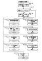
図20は、図14に示されたメイン処理における演出制御プロセス処理(ステップS705)を示すフローチャートである。演出制御プロセス処理では、演出制御プロセスフラグの値に応じてステップS800〜S806のうちのいずれかの処理が行われる。各処理において、以下のような処理が実行される。 FIG. 20 is a flowchart showing the effect control process (step S705) in the main process shown in FIG. In the effect control process, any one of steps S800 to S806 is performed according to the value of the effect control process flag. In each process, the following process is executed.
変動パターンコマンド受信待ち処理(ステップS800):コマンド受信割込処理によって、変動時間を特定可能な演出制御コマンド(変動パターンコマンド)を受信したか否か確認する。例えば、変動パターンコマンドが受信されたことを示すフラグ(変動パターン受信フラグ)がセットされたか否か確認する。変動パターン受信フラグは、コマンド解析処理によって、変動パターン指定の演出制御コマンドが受信されたことが確認された場合にセットされる。変動パターン指定の演出制御コマンドが受信されたことを確認したら、演出制御プロセスフラグの値をステップS801に応じた値に更新する。 Fluctuation pattern command reception waiting process (step S800): It is confirmed whether or not an effect control command (variation pattern command) capable of specifying the fluctuation time is received by the command reception interrupt process. For example, it is confirmed whether or not a flag (variation pattern reception flag) indicating that a variation pattern command has been received is set. The variation pattern reception flag is set when it is confirmed by command analysis processing that a variation pattern designation effect control command has been received. When it is confirmed that the effect control command designating the variation pattern has been received, the value of the effect control process flag is updated to a value corresponding to step S801.
エフェクト選択処理(ステップS801):エフェクト処理を伴う演出を行うか否かと、行う場合のエフェクト処理の種類を決定する。その後、演出制御プロセスフラグの値をステップS802に応じた値に更新する。 Effect selection process (step S801): It is determined whether or not an effect accompanied by an effect process is to be performed, and the type of effect process to be performed. Thereafter, the value of the effect control process flag is updated to a value corresponding to step S802.
全図柄変動開始処理(ステップS802):可変表示部9における左中右図柄の変動を開始させる。その後、演出制御プロセスフラグの値をステップS803に応じた値に更新する。
All symbol variation start processing (step S802): The variation of the left middle right symbol in the
図柄変動中処理(ステップS803):変動パターンを構成する各変動状態(変動速度等)の切替タイミングを制御するとともに、変動時間の終了を監視する。また、左右図柄の停止制御を行う。その後、演出制御プロセスフラグの値をステップS804に応じた値に更新する。なお、スーパーリーチ4による演出がなされエフェクト4の処理を行うことに決定されている場合には、変動時間が終了する前に、ゲームの表示演出の制御も行う。その間、左中右図柄を揺れ変動状態にさせる。
Symbol variation processing (step S803): Controls the switching timing of each variation state (variation speed, etc.) constituting the variation pattern and monitors the end of the variation time. In addition, stop control of the left and right symbols is performed. Thereafter, the value of the effect control process flag is updated to a value corresponding to step S804. In addition, when the effect by the
全図柄停止設定処理(ステップS804):変動時間の終了時に、全図柄停止を指示する演出制御コマンド(特別図柄停止の演出制御コマンド:確定コマンド)を受信していたら、図柄の変動を停止し停止図柄(確定図柄)を表示する制御を行う。その後、演出制御プロセスフラグの値をステップS805に応じた値に更新する。 All symbol stop setting process (step S804): If an effect control command (special symbol stop effect control command: confirmation command) is received at the end of the variation time, the symbol variation is stopped and stopped. Control to display a symbol (definite symbol) is performed. Thereafter, the value of the effect control process flag is updated to a value corresponding to step S805.
大当り表示処理(ステップS805):変動時間の終了後、確変大当り表示または通常大当り表示の制御を行う。その後、演出制御プロセスフラグの値をステップS806に応じた値に更新する。 Big hit display process (step S805): After the end of the fluctuation time, the control of the probability variable big hit display or the normal big hit display is performed. Thereafter, the value of the effect control process flag is updated to a value according to step S806.
大当たり遊技中処理(ステップS806):大当たり遊技中の制御を行う。例えば、大入賞口開放前表示や大入賞口開放時表示の演出制御コマンドを受信したら、ラウンド数の表示制御等を行う。その後、演出制御プロセスフラグの値をステップS800に応じた値に更新する。 Process during jackpot game (step S806): Control during jackpot game is performed. For example, when an effect control command for display before opening the big winning opening or display when opening the big winning opening is received, display control of the number of rounds is performed. Thereafter, the value of the effect control process flag is updated to a value according to step S800.
図21は、変動パターン毎に設定されているプロセスデータの一構成例を示す説明図である。プロセスデータは、プロセスタイマ設定値と演出制御実行データの組み合わせが複数集まったデータで構成されている。演出制御実行データは、表示制御実行データとランプ制御実行データと音声データとを含む。表示制御実行データには、特別図柄の変動中における可変表示装置9の表示状態(変動速度等)を示すデータが設定されている。例えば、表示制御実行データ1には、可変表示開始時の可変表示装置9の表示状態を示すデータが設定されている。また、ランプ制御実行データには、特別図柄の変動中におけるランプ・LEDの表示状態を示すデータが設定されている。例えば、ランプ制御実行データ1には、可変表示開始時のランプ・LEDの表示状態を示すデータが設定されている。音声データには、特別図柄の変動中におけるスピーカ27の音発生状態を示すデータが設定されている。例えば、音声データ1には、可変表示開始時の音発生状態を示すデータが設定されている。
FIG. 21 is an explanatory diagram showing a configuration example of process data set for each variation pattern. The process data is composed of data obtained by collecting a plurality of combinations of process timer set values and presentation control execution data. The effect control execution data includes display control execution data, lamp control execution data, and audio data. In the display control execution data, data indicating the display state (variation speed, etc.) of the
そして、特別図柄の変動中において、表示状態を切り替えるタイミング(例えば、図柄の変動速度を切り替えるタイミング、可変表示装置9において新たなキャラクタが登場するタイミング、ランプ・LEDを点灯状態から消灯状態に切り替えるタイミング)が到来すると、演出制御手段は、プロセスデータにおける次の演出制御実行データ(表示制御実行データ、ランプ制御実行データ、音声データ)に従って、可変表示装置9およびランプ・LEDの表示状態を制御したり、音声データを音声出力基板70に出力したりする。プロセスタイマ設定値には、切替のタイミングに応じた時間が設定されている。
Then, during the change of the special symbol, the timing for switching the display state (for example, the timing for switching the symbol variation speed, the timing for the appearance of a new character in the
図21に示すプロセスデータは、演出制御基板80におけるROMに格納されている。また、プロセスデータは、各変動パターンのそれぞれに応じて用意されている。さらに、それぞれの変動パターンについても、予告演出の種類やエフェクト処理の種類毎にプロセスデータを用意しておけば、演出制御手段は、変動開始時に該当するプロセスデータを選択するだけで、容易に可変表示中の演出制御を実行することができる。
The process data shown in FIG. 21 is stored in the ROM of the
すなわち、表示制御実行データには、動画像(ムービーデータ)を使用するか否かを示す情報、可変表示装置9上に表示する識別情報(特別図柄)の表示領域の大きさを特定する情報、表示領域それぞれの表示位置、識別情報の移動速度と移動方向、識別情報の拡大・縮小率、識別情報の透過率、識別情報の回転角度などの情報も含まれる。
That is, the display control execution data includes information indicating whether or not to use a moving image (movie data), information specifying the size of the display area of identification information (special symbol) displayed on the
「表示領域の大きさを特定する情報」とは、可変表示装置9の表示画面のうち、左図柄、中図柄、右図柄をそれぞれ表示する領域のサイズを示す情報を意味する。なお、各特別図柄を表示する領域のサイズは、1回の特別図柄の可変表示中に変化(拡大、縮小、変形)することがある。
The “information specifying the size of the display area” means information indicating the size of the area for displaying the left symbol, the middle symbol, and the right symbol on the display screen of the
ROM122には、特別図柄の種類や配列を示す情報(識別情報配列特定情報:具体的には、例えば特別図柄の番号「0」〜「9」)と、特別図柄の画像変化を示す情報や画像変化順を示す情報(画像変化特定情報:例えば、図17に示す(A)→(E)への方向)とにより、特別図柄を示す画像データの格納領域を特定するためのインデックスデータのデータテーブルが記憶されている。すなわち、CGROM83に記憶されているそれぞれの画像データ(画像要素データ)のアドレスは、インデックスデータのデータテーブルを用いて特定される。
The ROM 122 stores information indicating the type and arrangement of the special symbol (identification information arrangement specifying information: specifically, for example, the special symbol numbers “0” to “9”), and information and images indicating the special symbol image change. A data table of index data for specifying a storage area of image data indicating a special symbol based on information indicating the change order (image change specifying information: for example, a direction from (A) to (E) shown in FIG. 17). Is remembered. That is, the address of each image data (image element data) stored in the
演出制御用CPU101は、プロセスデータにおける表示制御実行データとROM122に記憶されているその他の情報(識別情報配列特定情報等)とを用いてアニメーション変動を実現することができる。すなわち、表示制御実行データにおける特別図柄の移動速度と移動方向を用いて、GCL106に、特別図柄を変動表示させる速度と方向を指定することができる。また、表示領域それぞれの表示位置を示す情報で特別図柄等の表示位置を指定することができる。さらに、表示領域の大きさを特定する情報により、特別図柄の表示領域の大きさを特定することができる。また、識別情報配列特定情報が示す特別図柄を変動表示させる順序(例えば、0→1→・・・→9)と画像変化特定情報が示す特別図柄の画像変化順や画像変化のさせ方(例えば、図17に示す(A)→(E)への方向への画像変化)とに従って、複数種類の表示に必要な識別情報画像要素データ(例えば、図17の(A)から(E)に示す画像データ)をVRAMに記憶(展開)させる。
The
GCL106は、指定された速度および方向と特定された表示領域の大きさとにもとづいて、VRAMに順次展開される画像データ(画像要素データ)を選択し、選択した画像要素データをフレームバッファの所定位置(表示領域の表示位置を示す情報等によって示される位置)に配置することによって、フレームバッファに1画面分の画像データを作成することができる。
The
そして、例えば、プロセスデータとして、スーパーリーチ1を実現するときに用いられるものとして、エフェクト処理を伴うものとエフェクト処理1,2,3を伴わないものとの4種類が用意されている。エフェクト処理1を伴うスーパーリーチ1を実現するために用いられるプロセスデータには、図12において(1)で示されるタイミングが到来すると用いられる演出制御実行データに、エフェクト処理1を実現するためのデータ(発展演出を開始することを示すデータ)を設定する。なお、そのように、多数のプロセスデータを用意してエフェクト処理を実現する方法は一例であって、スーパーリーチ1〜4のそれぞれを実現するときに用いられるプロセスデータを1種類にして、表示制御用CPU101が、スーパーリーチ1〜4のそれぞれに応じて、変動開始時からの時間を測定し、図12(1)〜(4)に示すタイミングが到来すると、GCL106に対して、発展演出を開始することを示す指示を与えるようにしてもよい。
For example, there are four types of process data that are used when realizing the
図22は、エフェクト選択処理(ステップS801)を示すフローチャートである。エフェクト選択処理において、演出制御用CPU101は、遊技制御手段から受信した変動パターンを示す演出制御コマンド(変動パターンコマンド)が、スーパーリーチ1〜4のいずれかを示しているか否か確認する(ステップS811)。スーパーリーチ1〜4のいずれかを示している場合には、乱数を抽出する(ステップS812)。すなわち、乱数カウンタの値を読み出し、読み出した値を乱数の値とする。そして、乱数値に応じて、エフェクト処理を実行するか否か決定するとともに、実行することに決定した場合にはエフェクト処理の種類を決定する(ステップS813)。
FIG. 22 is a flowchart showing the effect selection process (step S801). In the effect selection process, the
例えば、ROM122には、エフェクト処理を実行するか否かと、実行する場合のエフェクト処理の種類(具体的には、エフェクト画像の種類および演算の種類)とが数値(乱数値がとりうる範囲における数値)に対応して設定されているエフェクト処理選択テーブルが格納されている。演出制御用CPU101は、抽出した乱数値とエフェクト処理選択テーブルに設定されている各数値とを比較し、一致した数値に対応するエフェクト処理の種類またはエフェクト処理を実行しない旨を選択する。そして、演出制御プロセスフラグの値を、全図柄変動開始処理(ステップS802)に応じた値にする。
For example, in the ROM 122, whether or not to execute the effect processing and the type of effect processing (specifically, the type of the effect image and the type of calculation) in the case of execution are numerical values (numerical values in a range that the random number can take). ) Is stored in the effect processing selection table set in correspondence with (). The
ステップS802の全図柄変動開始処理では、演出制御用CPU101は、まず、使用するプロセスデータ(変動パターンテーブルともいう。)を選択し、プロセスタイマ設定値に対応したプロセスタイマをスタートさせる。また、プロセスデータ中の表示制御実行データ1、ランプ制御実行データ1および音声データ1にもとづく制御を開始する。次いで、変動時間タイマ(特別図柄の変動時間に応じたタイマ)をスタートし、演出制御プロセスフラグの値を図柄変動中処理(ステップS803)に対応した値にする。
In the all symbol variation start process in step S802, the
図23は、図柄変動中処理(ステップS803)を示すフローチャートである。図柄変動中処理において、演出制御用CPU101は、まず、表示制御処理を実行する(ステップS830)。そして、プロセスタイマがタイムアウトしたら(ステップS831)、プロセスデータにおける演出制御実行データの切り替えを行う(ステップS832)。すなわち、プロセスデータにおいて、次に設定されているプロセスタイマをスタートさせるとともに、次に設定されている表示制御実行データにもとづいてLCD制御を行う。また、プロセスデータ中の次に設定されているランプ制御実行データにもとづいてランプ・LED制御を行う。さらに、プロセスデータ中の次に設定されている音番号データを示す音声データ1を音声出力基板70に出力する。なお、この実施の形態では、プロセスタイマは、例えば、変動速度が切り替わるときや、特定のキャラクタを表示させたりするタイミングでタイムアウトするように設定されているとする。
FIG. 23 is a flowchart showing the symbol variation processing (step S803). In the symbol variation processing, the
切替後の表示制御実行データに発展演出を開始することを示すデータが設定されていた場合には、演出制御用CPU101の内部状態を展開指示(VRAMからフレームバッファに新たな画像データを展開することを示す指示)を禁止する状態に設定するとともに(ステップS833,S834)、発展演出(図11および図18参照)を開始させるために、GCL106に対して、可変表示装置9側に画像データを出力していたフレームバッファの内容をVRAMに複写することを示す複写指示を出力する(ステップS835)。なお、演出制御用CPU101からGCL106への指示は、演出制御用CPU101が描画制御レジスタ95に指示を書き込むことによって、GCL106に出力されることになる。
When data indicating the start of the development effect is set in the display control execution data after switching, an instruction to expand the internal state of the effect control CPU 101 (expand new image data from the VRAM to the frame buffer) Is set to a state of prohibiting (steps S833 and S834), and image data is output to the
また、プロセスデータに特別図柄の可変表示を再開することを示すデータが設定されていた場合には(ステップS836)、GCL106に対して、可変表示装置9における動画表示を再開させるための指示を与える。すなわち、演出制御用CPU101は、まず、フレームバッファの画像データを消去することを示すクリア指示をGCL106に出力する(ステップS837)。次いで、ステップS813で選択されたエフェクト処理で用いるエフェクト用画像のCGROM83におけるアドレスとともに、そのエフェクト用画像をVRAMに読み出すことを指示する読出指示を出力する(ステップS838)。
If the data indicating that the special symbol variable display is resumed is set in the process data (step S836), the
さらに、ステップS835の処理による指示に応じてGCL106がフレームバッファに複写した画像データ(ステップS908参照)を、フレームバッファに戻すことを示す展開指示を出力する(ステップS839)。また、ステップS838の処理による指示に応じてGCL106がフレームバッファに読み出した画像データ(ステップS906参照)すなわちエフェクト用画像の画像データと、そのときのフレームバッファの内容との間で演算を行うことによって、フレームバッファに配置された画像データとエフェクト用画像の画像データとを合成することを示す描画指示(演算指示)を出力する(ステップS840)。そして、演出制御用CPU101の内部状態を展開指示禁止の状態から元の状態(展開指示禁止でない状態)に戻す(ステップS841)。なお、描画指示(演算指示)には、演算の内容(例えば、加算、減算、半透明化処理を実現するための演算など)を示す情報と、フレームバッファにおけるエフェクト用画像の設定位置を示す情報とが付随する。
Further, in response to the instruction by the process in step S835, a development instruction is output indicating that the image data copied by the
この実施の形態では、プロセスデータにおいて、図24に示すように、発展演出を開始することを示す表示制御実行データの後に、可変表示を再開することを示す表示制御実行データが設定されている。そして、発展演出を開始することを示す表示制御実行データの直前に設定されているプロセスタイマの値が、表示画面が静止している期間(エフェクト演出が実行される期間でもある)に相当する。また、可変表示を再開することを示す表示制御実行データには、スーパーリーチ演出開始時のデータも含まれている。例えば、特別なキャラクタを表示させることを示すデータが含まれている。従って、演出制御手段は、動画表示を再開するときに、スーパーリーチ演出を開始することができる。 In this embodiment, in the process data, as shown in FIG. 24, display control execution data indicating that variable display is resumed is set after display control execution data indicating that the development effect is started. The value of the process timer set immediately before the display control execution data indicating the start of the development effect corresponds to the period during which the display screen is stationary (also the period during which the effect effect is executed). The display control execution data indicating that variable display is resumed includes data at the start of super reach production. For example, data indicating that a special character is displayed is included. Therefore, the effect control means can start the super reach effect when resuming the moving image display.
そして、変動時間タイマがタイムアウトしていたら(ステップS842)、特別図柄停止の演出制御コマンドの受信を監視するための監視タイマをスタートさせ(ステップS843)、演出制御プロセスフラグの値を全図柄停止待ち処理に対応した値にする(ステップS844)。なお、演出制御用CPU101は、特別図柄停止の演出制御コマンドを受信していたら、変動時間タイマがタイムアウトしていなくても、演出制御プロセスフラグの値を全図柄停止処理に対応した値にする。
If the variable time timer has timed out (step S842), a monitoring timer for monitoring the reception of the special symbol stop effect control command is started (step S843), and the value of the effect control process flag is set to all symbol stop waits. A value corresponding to the process is set (step S844). If the
図25は、GCL106が定期的に発生するVブランク割込に応じて演出制御用CPU101が実行する表示制御処理を示すフローチャートである。表示制御処理において、演出制御用CPU101は、内部状態が展開指示禁止の状態でなければ(ステップS721)、画像データを可変表示装置9側に出力するフレームバッファを切り替える指示をGCL106に出力する(ステップS722)。この実施の形態では、フレームバッファはダブルバッファ構成であって、一方のフレームバッファから画像データが可変表示装置9側に出力されている間、他方のフレームバッファにVRAMの画像データを展開(書込)することが可能である。GCL106は、フレームバッファを切り替える指示に応じて、画像データを可変表示装置9側に出力するフレームバッファを切り替える。
FIG. 25 is a flowchart showing a display control process executed by the
そして、演出制御用CPU101は、画像データを可変表示装置9側に出力するフレームバッファ(読出側のフレームバッファ)から画像データを可変表示装置9側に出力することを示す表示指示をGCL106に出力する(ステップS723)。また、次のコマにおいて表示されるべき画像の画像データをVRAMから書込側のフレームバッファすなわち読出側でないフレームバッファに書き込むことを示す展開指示を、表示されるべき画像の画像データのVRAMにおける位置を指定する情報とともにGCL106に出力する(ステップS724)。
Then, the
また、演出制御用CPU101は、次のコマにおいて表示されるべき図柄の種類を判定して、VRAMに展開されている特別図柄の画像データを切り替えるかべきか否か確認する(ステップS725)。この実施の形態では、可変表示装置9の特別図柄の表示領域において、33.3msが経過する毎に1コマずつ表示切替がなされてスクロール表示が実現されるとする。図17に例示されたような表示方法を用いた場合、5回の表示切替が実行されると、次のコマにおいて表示されるべき画像データがVRAMに存在しないことになるので、次のアニメーション画像が展開されるべきタイミングが到来することになる。そのようなタイミングになると、演出制御用CPU101は、VRAMに展開するアニメーション画像を切り替えるための指示をGCL106に出力する。
Further, the
具体的には、VRAMに展開されているアニメーション画像をクリアすることを示すクリア指示をGCL106に出力する(ステップS726)。また、新たにVRAMに展開されるべきアニメーション画像を特定し(ステップS727)、特定したアニメーション画像のCGROM83におけるアドレスとともに、アニメーション画像をVRAMに展開することを示す読出指示をGCL106に出力する(ステップS728)。なお、図17に例示したような表示制御を行うために、演出制御用CPU101は、それぞれのタイミングにおいて、直前のタイミングにおいて抽出した一連画像の画像データとは異なる一連画像の画像データから、直前の抽出タイミングにおいて抽出した領域に対してずれた領域から画像データを抽出するようにGCL106に対して指示する。すなわち、図17において(A)〜(E)に示されているように、領域をずらして画像デーのが抽出が行われる。
Specifically, a clear instruction indicating that the animation image developed in the VRAM is cleared is output to the GCL 106 (step S726). Also, an animation image to be newly developed in the VRAM is specified (step S727), and a read instruction indicating that the animation image is expanded in the VRAM is output to the
アニメーション画像の切替に際して、演出制御用CPU101は、例えば、「4」および「3」の特別図柄についてVRAMへの展開を行う場合には、「4」および「3」のそれぞれについて複数種類の態様の画像データを特定して、表示される順序に従って並べてVRAMに展開されるようにGCL106に指示を与える。
When the animation image is switched, for example, when the special symbols “4” and “3” are expanded to the VRAM, the
図26は、GCL106の処理を示すフローチャートである。GCL106は、演出制御用CPU101から表示指示(ステップS723参照)を入力すると、読出側のフレームバッファから画像データを可変表示装置9側に出力する処理を開始する(ステップS901,S902)。
FIG. 26 is a flowchart showing the processing of the
また、演出制御用CPU101から展開指示(ステップS839,S724参照)を入力すると、画像データをVRAMにおける指定された領域から抽出して(クリッピングして)フレームバッファに書き込む(ステップS903,S904)。演出制御用CPU101から読出指示(ステップS838,S728参照)を入力すると、指定されたCGROM83におけるアドレスから画像データを読み出してVRAMに書き込む(ステップS905,S906)。
When a development instruction (see steps S839 and S724) is input from the
また、演出制御用CPU101から複写指示(ステップS835参照)を入力すると、可変表示装置9に対して画像データを出力していたフレームバッファの内容をVRAMに複写する(ステップS907,S908)。また、クリア指示を入力すると(ステップS837,S726)、該当する領域にクリアデータを書き込んで内容をクリアする(ステップS909,S910)。
When a copy instruction (see step S835) is input from the
そして、GCL106は、演出制御用CPU101から描画指示(ステップS840参照)を入力すると、以下のような制御を行う。なお、描画指示を入力する直前に、演出制御用CPU101から、フレームバッファに複写した画像データを、フレームバッファに戻すことを示す展開指示を入力している(ステップS839,S840参照)。その結果、ステップS904で、そのような画像データすなわち発展演出が開始された時点の画像データ(一時静止表示時の表示画像データ)がフレームバッファに戻されている。また、ステップS838の処理による読出指示に応じて、ステップS906の処理で、エフェクト用画像の画像データがVRAMに存在している。GCL106は、描画指示に応じて、描画指示に付随する演算の内容が示す演算によって、フレームバッファの内容とエフェクト用画像の画像データとの間で演算(例えば、加算、減算、半透明化処理を実現するための演算など)を行う。その結果、フレームバッファの内容とエフェクト用画像とが合成された、図11(C)に例示するような画像の画像データがフレームバッファに生成される。なお、VRAMに展開されたエフェクト用画像の画像データは、例えば、特別図柄の変動終了時にクリアされる。
When the drawing instruction (see step S840) is input from the
以上のような制御によって、特別図柄のスクロール表示すなわち可変表示(変動)が実現され、さらに、図11に例示されたような表示画面全体の一時停止および可変表示再開の表示制御が実現される。そして、そのような表示制御を行うときに、演出制御手段(演出制御用CPU101とGCL106とをを含む)は、フレームバッファに保存されている画像データ、すなわち一時停止時の画像データ(1画面全体)を、一旦、VRAMに複写し、VRAMに複写された画像データとエフェクト用画像のデータとを対象として演算処理を実行する。
With the control as described above, scroll display of special symbols, that is, variable display (fluctuation) is realized, and further, display control for pausing and resuming variable display as shown in FIG. 11 is realized. When such display control is performed, the effect control means (including the
よって、一時停止時の特別図柄の表示状態を含む画面状態がどのような状態であっても、上記の処理によって、一時停止と再開の制御を実行することができる。従来の方法では、一時停止時の画面に変形が施された図11(C)に例示された変形画面を表示しようとすると、様々な一時停止時の画面状態のそれぞれに応じた変形画面の画像データをキャラクタROMに格納しておき、その画像データを読み出して図11(C)に例示された画面表示を実現するので、キャラクタROMの容量を増大させていた。また、キャラクタROMの容量を増大させないようにするために、1種類または数種類の画像データしかキャラクタROMに格納しない場合には、一時停止時の画面状態を1種類または数種類にしかできない。従って、一時停止および再開の表示制御を多様にすることはできない。 Therefore, regardless of the state of the screen state including the display state of the special symbol at the time of suspension, the suspension and resumption control can be executed by the above processing. In the conventional method, when the modified screen illustrated in FIG. 11C in which the screen at the time of suspension is modified is displayed, the image of the modified screen corresponding to each of the various screen states at the time of suspension. Since the data is stored in the character ROM and the image data is read out to realize the screen display illustrated in FIG. 11C, the capacity of the character ROM is increased. Further, in order not to increase the capacity of the character ROM, when only one type or several types of image data are stored in the character ROM, the screen state at the time of pause can only be one type or several types. Therefore, it is not possible to diversify the display control of pause and resume.
また、演出制御手段は、識別情報の可変表示が行われる可変表示期間におけるあらかじめ決められている複数の時点のうちのいずれか時点で画像データ更新手段の動作を停止させる制御を行い(図13参照)、画像データ更新手段の動作の停止を解除するときに、表示演出の態様をスーパーリーチ演出に変更する(スーパーリーチに発展させる)のであるが、この実施の形態では、複数の時点のそれぞれは、スーパーリーチ1〜4のそれぞれにおいてあらかじめ決められている。しかし、変動パターンに応じて画像データ更新手段の動作を停止させるタイミングを決めておくのではなく、演出制御手段が、1つの変動パターンによる特別図柄の変動を実行するように遊技制御手段から指示された場合に、例えば抽選によって画像データ更新手段の動作を停止させるタイミングを決定し、その変動パターンに従って特別図柄の変動を行っている最中に画像データ更新手段の動作を停止させるようにしてもよい。
Further, the effect control means performs control to stop the operation of the image data update means at any one of a plurality of predetermined time points in the variable display period in which the variable display of the identification information is performed (see FIG. 13). ), When canceling the stop of the operation of the image data updating means, the mode of the display effect is changed to the super reach effect (development to super reach), but in this embodiment, each of the plurality of time points is , And are determined in advance in each of the
また、上記の実施の形態では、パチンコ遊技機として、始動入賞にもとづいて可変表示部9に可変表示される特別図柄の停止図柄が所定の図柄の組み合わせになると所定の遊技価値が遊技者に付与可能になる第1種パチンコ遊技機を例示したが、表示装置を備えていれば、始動入賞にもとづいて開放する電動役物の所定領域への入賞があると所定の遊技価値が遊技者に付与可能になる第2種パチンコ遊技機や、始動入賞にもとづいて可変表示される図柄の停止図柄が所定の図柄の組み合わせになると開放する所定の電動役物への入賞があると所定の権利が発生または継続する第3種パチンコ遊技機であっても、本発明を適用できる。さらに、スロット機に対しても本発明を適用することができる。
Further, in the above embodiment, as a pachinko gaming machine, a predetermined game value is given to a player when a special symbol stop symbol variably displayed on the
また、上記の実施の形態では、以下のような遊技機も開示されている。 In the above embodiment, the following gaming machines are also disclosed.
遊技者が所定の遊技を実行可能であり、動画像を表示することによって表示演出を行う画像表示手段(例えば、可変表示装置9)を備えた遊技機であって、画像表示手段が表示する画面の画像データを作成して該画像表示手段に出力する画像表示制御手段(例えば、演出制御用CPU101とGCL106とを含む演出制御手段)を備え、画像表示制御手段が、複数種類の画像要素データを記憶する画像要素データ記憶手段(例えば、CGROM83)から、画面表示に用いられる画像要素データを読み出して一時記憶手段(例えば、SDRAM84に形成されているVRAM)に記憶させる画像要素データ読出手段(例えば、GCL106におけるステップS906の処理を実行する部分)と、一時記憶手段に記憶されている画像要素データから、画像表示手段が表示する画面の画像データの作成に用いる画像要素データを選択し、選択した画像要素データにもとづき画像データを仮想表示領域(例えば、SDRAM84に形成されているフレームバッファ)に作成する画像データ作成手段(例えば、演出制御用CPU101によるステップS724の処理にもとづいてGCL106におけるステップS904の処理を実行する部分)と、仮想表示領域に作成された画像データを画像表示手段に出力する画像データ出力手段(例えば、演出制御用CPU101によるステップS723の処理にもとづいてGCL106におけるステップS902の処理を実行する部分)と、画像表示手段に表示されている画面を静止表示させるために、画像データ作成手段による新たな画像要素データの選択を禁止する一時停止制御手段(例えば、演出制御用CPU101におけるステップS834,S721の処理を実行する部分)と、一時停止制御手段が画像要素データの選択を禁止したときに仮想表示領域に作成されている1画面分の画像データを画面画像要素データとして一時記憶手段に記憶させる一時記憶制御手段(例えば、演出制御用CPU101によるステップS835の処理にもとづいてGCL106におけるステップS908の処理を実行する部分)と、一時停止制御手段による新たな画像要素データの選択の禁止を解除する一時停止解除手段(例えば、演出制御用CPU101におけるステップS841,S721の処理を実行する部分)とを含み、画像データ作成手段が、一時停止解除手段により禁止が解除されたときに、画面画像要素データと他の画像要素データとを用いて静止表示後に新たに表示する画面の画像データを作成する(例えば、演出制御用CPU101によるステップS840の処理にもとづいてGCL106におけるステップS912の処理)ことを特徴とする遊技機。
A game machine that is provided with an image display means (for example, a variable display device 9) that allows a player to execute a predetermined game and performs a display effect by displaying a moving image, and a screen displayed by the image display means The image display control means (for example, the effect control means including the
画像表示手段に表示されている画面を一時的に静止表示させるために画像データ作成手段の画像要素データの選択を停止させ、画像データ作成手段の選択が停止したときに仮想記憶領域に作成されていた1画面分の画像データを一時記憶手段に記憶させ、一時記憶手段に記憶された画面画像要素データと他の画像要素データとを用いて静止表示状態が終了するときの新たな画像データを作成するように構成したので、記憶容量を増大させることなく、一時停止時の場面とは異なる種々の場面から再び動画像の表示を開始させることができる。 In order to temporarily display the screen displayed on the image display means, the selection of the image element data of the image data creation means is stopped, and the screen is created in the virtual storage area when the selection of the image data creation means is stopped. The image data for one screen is stored in the temporary storage means, and new image data when the still display state ends is created using the screen image element data and other image element data stored in the temporary storage means. Thus, the display of the moving image can be started again from various scenes different from the scene at the time of pause without increasing the storage capacity.
また、上記の実施の形態では、以下のような特徴的な要件が付加された遊技機も開示されている。 In the above embodiment, a gaming machine to which the following characteristic requirements are added is also disclosed.
可変表示の開始条件の成立にもとづいて、画像表示手段における複数の表示領域のそれぞれにおいて各々を識別可能な複数種類の識別情報(例えば特別図柄)の可変表示を開始し、複数の表示領域における識別情報の表示結果が特定表示結果(例えば大当り図柄)となったときに遊技状態を遊技者にとって有利な状態(例えば大当り遊技状態)に制御可能な遊技機であって、画像表示制御手段が、識別情報の可変表示において、あらかじめ決められている複数種類の特殊演出(例えばリーチ演出)のうちのいずれかの特殊演出を画像表示手段において実行する特殊演出手段(例えば、演出制御手段のうち、遊技制御手段からのリーチに応じた変動パターンコマンドにもとづいて、リーチ演出に用いられるプロセスデータを使用してステップS803を実行する部分)を含み(図8参照)、複数種類の特殊演出は、他の特殊演出に比べて、識別情報の表示結果が特定表示結果となるときに実行される割合が高い特別特殊演出(例えばスーパーリーチ演出)を含み、特殊演出手段が、識別情報の可変表示が行われる可変表示期間中に画像表示手段に表示されている画面を静止表示させた後に、特別特殊演出の実行を開始する(図12および図24参照)ように構成されている遊技機。 Based on the establishment of the variable display start condition, variable display of a plurality of types of identification information (for example, special symbols) that can be identified in each of the plurality of display areas in the image display means is started, and identification in the plurality of display areas is started. A gaming machine capable of controlling a gaming state advantageous to a player (for example, a big hit gaming state) when a display result of information becomes a specific display result (for example, a big hit symbol). In variable display of information, special effect means (for example, game control among effect control means) that executes any one of a plurality of predetermined special effects (for example, reach effect) in the image display means. Based on the variation pattern command according to the reach from the means, the process data used for reach production is used to perform step S. 03) (see FIG. 8), the special effects of a plurality of types are more highly executed when the display result of the identification information becomes the specific display result than the other special effects. Including special effects (for example, super-reach effects), and the special effects means causes the screen displayed on the image display means to remain stationary during the variable display period in which the identification information is variably displayed, and then executes the special special effects. A gaming machine configured to start (see FIG. 12 and FIG. 24).
そのように構成されている場合には、識別情報の可変表示が行われる可変表示期間中に画像表示手段に表示されている画面を静止表示させた後に、特別特殊演出の実行を開始するように構成されているので、識別情報の可変表示の内容のみでなく、画面が静止表示されることを遊技者が期待するようになり、興趣を向上させることができる。 In such a case, the special special effect is started after the screen displayed on the image display means is statically displayed during the variable display period in which the identification information is variably displayed. Since it is configured, the player can expect not only the contents of the variable display of the identification information but also the screen to be displayed statically, and the interest can be improved.
可変表示の開始条件の成立にもとづいて、画像表示手段における複数の表示領域のそれぞれにおいて各々を識別可能な複数種類の識別情報(例えば特別図柄)の可変表示を開始し、複数の表示領域における識別情報の表示結果が特定表示結果(例えば大当り図柄)となったときに遊技状態を遊技者にとって有利な状態(例えば大当り遊技状態)に制御可能な遊技機であって、画像要素データ記憶手段が、複数種類の識別情報のそれぞれについて、識別情報の態様を変化させるために用いる複数種類の識別情報画像要素データ(図10参照)を記憶し、画像表示制御手段が、識別情報を変動表示させる速度と方向を指定する変動方向速度指定手段(例えば、演出制御手段のうち、プロセスデータに設定されている識別情報の移動速度と移動方向の情報にもとづいてステップS832の処理を実行する部分)と、識別情報を表示するための表示領域の大きさを特定する表示領域特定手段(例えば、演出制御手段のうち、プロセスデータに設定されている表示領域の大きさを特定する情報にもとづいてステップS832の処理を実行する部分)とを含み、画像要素データ読出手段が、複数種類の識別情報を変動表示させる順序(例えば、0→1→・・・→9)と、各識別情報の態様を変化させる順序(例えば、図17に示す(A)→(E)への方向)に従って、複数種類の識別情報画像要素データ(図17参照)を一時記憶手段に記憶させ、画像データ作成手段が、一時記憶手段に記憶された複数種類の識別情報画像要素データから、変動方向速度指定手段により指定された速度および方向と表示領域特定手段により特定された表示領域の大きさとにもとづいて表示対象となる画像要素データ(例えば、図17に示すE21からE25のいずれか)を選択し、選択した画像要素データを用いて仮想表示領域に画像データを作成するように構成されている遊技機。 Based on the establishment of the variable display start condition, variable display of a plurality of types of identification information (for example, special symbols) that can be identified in each of the plurality of display areas in the image display means is started, and identification in the plurality of display areas is started. A gaming machine capable of controlling a gaming state to an advantageous state for a player (for example, a big hit gaming state) when a display result of information becomes a specific display result (for example, a big hit symbol), wherein the image element data storage means is For each of a plurality of types of identification information, a plurality of types of identification information image element data (see FIG. 10) used for changing the mode of the identification information is stored, and the image display control means variably displays the identification information. Fluctuating direction speed specifying means for specifying the direction (for example, the moving speed and moving direction of the identification information set in the process data in the effect control means The part that executes the process of step S832 based on the information) and the display area specifying means for specifying the size of the display area for displaying the identification information (for example, the process data of the effect control means is set in the process data). In which the image element data reading means variably displays a plurality of types of identification information (for example, 0 → 1 →). ... → 9) and a plurality of types of identification information image element data (see FIG. 17) according to the order of changing the mode of each identification information (for example, the direction from (A) to (E) shown in FIG. 17). The speed and direction designated by the variable direction speed designation means from the plurality of types of identification information image element data stored in the temporary storage means and stored in the temporary storage means. And image element data to be displayed (for example, any one of E21 to E25 shown in FIG. 17) based on the size of the display area specified by the display area specifying means, and using the selected image element data A gaming machine configured to create image data in a virtual display area.
そのように構成されている場合には、指定された速度および方向と特定された表示領域の大きさとにもとづいて表示対象となる画像要素データを選択し、選択した画像要素データを用いて仮想表示領域に画像データを作成するように構成されているので、識別情報を可変表示させながら、識別情報に対する装飾等を変えることができ、識別情報等の表示品位を向上させることができる。 If so configured, image element data to be displayed is selected based on the specified speed and direction and the size of the specified display area, and virtual display is performed using the selected image element data. Since the image data is created in the area, the decoration of the identification information can be changed while the identification information is variably displayed, and the display quality of the identification information can be improved.
画像データ作成手段が、静止画像表示後に新たに表示する画面の画像データを作成する際に、作成される画像データが異なるようにあらかじめ複数種類定められた演算方法(図19参照)のうちから、いずれかの演算方法を用いて画像データを作成する(例えば、ステップS812,S813の処理)ように構成された遊技機。 When the image data creation means creates image data for a screen to be newly displayed after displaying a still image, a plurality of types of computation methods (see FIG. 19) determined in advance so that the created image data are different from each other. A gaming machine configured to create image data using any of the calculation methods (for example, the processing in steps S812 and S813).
そのように構成されている場合には、記憶容量を増大させることなく、画像データ作成手段が作成する画像データの種類を多様にすることができる。 In such a configuration, the types of image data created by the image data creation means can be diversified without increasing the storage capacity.
本発明は、各々を識別可能な複数種類の識別情報を可変表示可能な可変表示手段を備えたパチンコ遊技機等の遊技機において、可変表示装置等において実行される演出のバリエーションを増やすために好適に適用することができる。 The present invention is suitable for increasing variations of effects executed in a variable display device or the like in a gaming machine such as a pachinko gaming machine equipped with variable display means capable of variably displaying a plurality of types of identification information that can identify each. Can be applied to.
1 パチンコ遊技機
9 可変表示装置
18 保留記憶表示エリア
31 主基板
56 CPU
80 演出制御基板
83 CGROM
84 SDRAM(VRAM,フレームバッファ)
101 演出制御用CPU
106 GCL(VDP)
1
80
84 SDRAM (VRAM, frame buffer)
101 CPU for effect control
106 GCL (VDP)
Claims (1)
前記識別情報の可変表示に応じたプロセスデータに従って、前記画像表示手段が表示する画面の画像データを作成して該画像表示手段に出力する画像表示制御手段を備え、
前記プロセスデータは、
前記識別情報の可変表示態様を示す可変表示態様データと前記可変表示態様データにもとづく前記識別情報の可変表示態様による制御時間を示す時間データとの組み合わせからなる複数のデータで構成され、
前記識別情報の可変表示の過程において演出が発展する発展演出を開始することを示すデータの後に、前記識別情報の可変表示を再開することを示すデータが設定され、
前記画像表示制御手段は、
複数種類の画像要素データを記憶する画像要素データ記憶手段から、画面表示に用いられる画像要素データを読み出して一時記憶手段に記憶させる画像要素データ読出手段と、
前記一時記憶手段に記憶されている画像要素データから、前記画像表示手段が表示する画面の画像データの作成に用いる画像要素データを選択し、選択した画像要素データにもとづき画像データを仮想表示領域に作成する画像データ作成手段と、
前記仮想表示領域に作成された画像データを前記画像表示手段に出力する画像データ出力手段と、
前記プロセスデータにもとづいて、前記発展演出の開始タイミングとなったことに応じて、前記画像表示手段に表示されている画面を静止表示させるために、前記画像データ作成手段による新たな画像要素データの選択を禁止する一時停止制御手段と、
前記一時停止制御手段が画像要素データの選択を禁止したときに前記仮想表示領域に作成されている1画面分の画像データを画面画像要素データとして前記一時記憶手段に記憶させる一時記憶制御手段と、
前記プロセスデータにもとづいて、前記識別情報の可変表示の再開タイミングとなったことに応じて、前記一時停止制御手段による新たな画像要素データの選択の禁止を解除する一時停止解除手段とを含み、
前記画像データ作成手段は、前記一時停止解除手段により禁止が解除されたときに、静止表示状態が終了するときの新たな画像データを、前記一時記憶手段に記憶された前記画面画像要素データと他の画像要素データとを用いて前記仮想表示領域に作成する
ことを特徴とする遊技機。 A gaming machine comprising an image display means for performing display effects including variable display of a plurality of types of identification information that allows a player to execute a predetermined game and that can identify each by displaying a moving image,
In accordance with the process data corresponding to the variable display of the identification information, comprising image display control means for creating image data of a screen displayed by the image display means and outputting the image data to the image display means,
The process data is
It is composed of a plurality of data composed of a combination of variable display mode data indicating a variable display mode of the identification information and time data indicating a control time based on the variable display mode of the identification information based on the variable display mode data.
The data indicating that the variable information display is resumed after the data indicating the start of the development effect that the effect develops in the process of variable display of the identification information is set,
The image display control means includes
Image element data reading means for reading image element data used for screen display and storing it in the temporary storage means from the image element data storage means for storing a plurality of types of image element data;
From the image element data stored in the temporary storage means, image element data used to create image data of the screen displayed by the image display means is selected, and the image data based on the selected image element data is stored in the virtual display area. Image data creation means to create;
Image data output means for outputting the image data created in the virtual display area to the image display means;
Based on the process data, in order to display the screen displayed on the image display unit in a stationary manner in response to the start timing of the development effect, new image element data by the image data generation unit is displayed. A suspension control means for prohibiting selection;
Temporary storage control means for storing image data for one screen created in the virtual display area as screen image element data in the temporary storage means when the temporary stop control means prohibits selection of image element data;
Based on the process data, the In response to a variable display of the recommencement timing of the identification information, viewing including a temporary stop canceling means for canceling the prohibition of selection of a new image element data by the suspension control unit ,
When the prohibition is canceled by the temporary suspension canceling unit, the image data creating unit is configured to send new image data when the still display state is terminated to the screen image element data stored in the temporary storage unit and the like. A game machine that is created in the virtual display area using the image element data .
Priority Applications (1)
| Application Number | Priority Date | Filing Date | Title |
|---|---|---|---|
| JP2009266423A JP4768063B2 (en) | 2009-11-24 | 2009-11-24 | Game machine |
Applications Claiming Priority (1)
| Application Number | Priority Date | Filing Date | Title |
|---|---|---|---|
| JP2009266423A JP4768063B2 (en) | 2009-11-24 | 2009-11-24 | Game machine |
Related Parent Applications (1)
| Application Number | Title | Priority Date | Filing Date |
|---|---|---|---|
| JP2004039695A Division JP4439939B2 (en) | 2004-02-17 | 2004-02-17 | Game machine |
Publications (3)
| Publication Number | Publication Date |
|---|---|
| JP2010042299A JP2010042299A (en) | 2010-02-25 |
| JP2010042299A5 JP2010042299A5 (en) | 2011-04-14 |
| JP4768063B2 true JP4768063B2 (en) | 2011-09-07 |
Family
ID=42014130
Family Applications (1)
| Application Number | Title | Priority Date | Filing Date |
|---|---|---|---|
| JP2009266423A Expired - Fee Related JP4768063B2 (en) | 2009-11-24 | 2009-11-24 | Game machine |
Country Status (1)
| Country | Link |
|---|---|
| JP (1) | JP4768063B2 (en) |
Families Citing this family (6)
| Publication number | Priority date | Publication date | Assignee | Title |
|---|---|---|---|---|
| JP6543206B2 (en) * | 2016-03-10 | 2019-07-10 | 株式会社平和 | Gaming machine |
| JP2020108657A (en) | 2019-01-07 | 2020-07-16 | 株式会社ユニバーサルエンターテインメント | Game machine |
| JP2020108654A (en) | 2019-01-07 | 2020-07-16 | 株式会社ユニバーサルエンターテインメント | Game machine |
| JP2020108655A (en) | 2019-01-07 | 2020-07-16 | 株式会社ユニバーサルエンターテインメント | Game machine |
| JP2020108656A (en) | 2019-01-07 | 2020-07-16 | 株式会社ユニバーサルエンターテインメント | Game machine |
| JP2020108653A (en) | 2019-01-07 | 2020-07-16 | 株式会社ユニバーサルエンターテインメント | Game machine |
-
2009
- 2009-11-24 JP JP2009266423A patent/JP4768063B2/en not_active Expired - Fee Related
Also Published As
| Publication number | Publication date |
|---|---|
| JP2010042299A (en) | 2010-02-25 |
Similar Documents
| Publication | Publication Date | Title |
|---|---|---|
| JP5265129B2 (en) | Slot machine | |
| JP4768063B2 (en) | Game machine | |
| JP2008142139A (en) | Game machine | |
| JP4439939B2 (en) | Game machine | |
| JP2005066176A (en) | Game machine | |
| JP6133064B2 (en) | Game machine | |
| JP2003290495A (en) | Game machine | |
| JP4405199B2 (en) | Game machine | |
| JP5802986B2 (en) | Game machine | |
| JP4255780B2 (en) | Game machine | |
| JP4472379B2 (en) | Game machine | |
| JP6302448B2 (en) | Slot machine | |
| JP2008253527A (en) | Slot machine | |
| JP2008142140A (en) | Game machine | |
| JP4364506B2 (en) | Game machine | |
| JP2005204735A (en) | Game machine | |
| JP2005013515A (en) | Game machine | |
| JP4468013B2 (en) | Game machine | |
| JP4286718B2 (en) | Game machine | |
| JP2005066030A (en) | Game machine | |
| JP5032763B2 (en) | Game machine | |
| JP2005185701A (en) | Game machine | |
| JP2005185700A (en) | Game machine | |
| JP2019083847A (en) | Game machine | |
| JP4286717B2 (en) | Game machine |
Legal Events
| Date | Code | Title | Description |
|---|---|---|---|
| A621 | Written request for application examination |
Free format text: JAPANESE INTERMEDIATE CODE: A621 Effective date: 20091124 |
|
| A521 | Written amendment |
Free format text: JAPANESE INTERMEDIATE CODE: A523 Effective date: 20110225 |
|
| TRDD | Decision of grant or rejection written | ||
| A01 | Written decision to grant a patent or to grant a registration (utility model) |
Free format text: JAPANESE INTERMEDIATE CODE: A01 Effective date: 20110607 |
|
| A01 | Written decision to grant a patent or to grant a registration (utility model) |
Free format text: JAPANESE INTERMEDIATE CODE: A01 |
|
| A61 | First payment of annual fees (during grant procedure) |
Free format text: JAPANESE INTERMEDIATE CODE: A61 Effective date: 20110615 |
|
| R150 | Certificate of patent or registration of utility model |
Ref document number: 4768063 Country of ref document: JP Free format text: JAPANESE INTERMEDIATE CODE: R150 Free format text: JAPANESE INTERMEDIATE CODE: R150 |
|
| FPAY | Renewal fee payment (event date is renewal date of database) |
Free format text: PAYMENT UNTIL: 20140624 Year of fee payment: 3 |
|
| R250 | Receipt of annual fees |
Free format text: JAPANESE INTERMEDIATE CODE: R250 |
|
| R250 | Receipt of annual fees |
Free format text: JAPANESE INTERMEDIATE CODE: R250 |
|
| R250 | Receipt of annual fees |
Free format text: JAPANESE INTERMEDIATE CODE: R250 |
|
| R250 | Receipt of annual fees |
Free format text: JAPANESE INTERMEDIATE CODE: R250 |
|
| R250 | Receipt of annual fees |
Free format text: JAPANESE INTERMEDIATE CODE: R250 |
|
| R250 | Receipt of annual fees |
Free format text: JAPANESE INTERMEDIATE CODE: R250 |
|
| LAPS | Cancellation because of no payment of annual fees |