JP2020108657A - Game machine - Google Patents
Game machine Download PDFInfo
- Publication number
- JP2020108657A JP2020108657A JP2019000409A JP2019000409A JP2020108657A JP 2020108657 A JP2020108657 A JP 2020108657A JP 2019000409 A JP2019000409 A JP 2019000409A JP 2019000409 A JP2019000409 A JP 2019000409A JP 2020108657 A JP2020108657 A JP 2020108657A
- Authority
- JP
- Japan
- Prior art keywords
- setting
- game
- big hit
- special
- special symbol
- Prior art date
- Legal status (The legal status is an assumption and is not a legal conclusion. Google has not performed a legal analysis and makes no representation as to the accuracy of the status listed.)
- Pending
Links
- 239000000463 material Substances 0.000 claims abstract description 30
- 230000002194 synthesizing effect Effects 0.000 claims description 4
- 230000004438 eyesight Effects 0.000 abstract description 12
- 238000000034 method Methods 0.000 description 1762
- 230000008569 process Effects 0.000 description 1686
- 230000008859 change Effects 0.000 description 1016
- 238000012545 processing Methods 0.000 description 862
- 238000012790 confirmation Methods 0.000 description 758
- 230000000694 effects Effects 0.000 description 461
- 238000003860 storage Methods 0.000 description 351
- 239000004973 liquid crystal related substance Substances 0.000 description 294
- 230000006870 function Effects 0.000 description 159
- 230000000875 corresponding effect Effects 0.000 description 131
- 238000007726 management method Methods 0.000 description 127
- 230000015654 memory Effects 0.000 description 105
- 238000004891 communication Methods 0.000 description 104
- 238000001514 detection method Methods 0.000 description 91
- 230000002159 abnormal effect Effects 0.000 description 90
- 238000010586 diagram Methods 0.000 description 86
- 230000004048 modification Effects 0.000 description 86
- 238000012986 modification Methods 0.000 description 86
- 238000012423 maintenance Methods 0.000 description 83
- 230000005540 biological transmission Effects 0.000 description 74
- 239000000872 buffer Substances 0.000 description 72
- 238000004519 manufacturing process Methods 0.000 description 56
- 230000001276 controlling effect Effects 0.000 description 49
- 238000010304 firing Methods 0.000 description 49
- 238000013461 design Methods 0.000 description 43
- 238000011084 recovery Methods 0.000 description 43
- 238000009877 rendering Methods 0.000 description 42
- 239000000758 substrate Substances 0.000 description 40
- 230000001965 increasing effect Effects 0.000 description 39
- 230000005236 sound signal Effects 0.000 description 38
- 238000012544 monitoring process Methods 0.000 description 37
- 238000003825 pressing Methods 0.000 description 37
- 239000000203 mixture Substances 0.000 description 36
- 230000002457 bidirectional effect Effects 0.000 description 31
- 239000000047 product Substances 0.000 description 31
- 238000009826 distribution Methods 0.000 description 30
- 230000002093 peripheral effect Effects 0.000 description 27
- 239000011521 glass Substances 0.000 description 22
- 230000007704 transition Effects 0.000 description 21
- 238000007792 addition Methods 0.000 description 17
- 230000009467 reduction Effects 0.000 description 16
- 230000008901 benefit Effects 0.000 description 15
- 230000007423 decrease Effects 0.000 description 15
- 239000000284 extract Substances 0.000 description 14
- 239000012636 effector Substances 0.000 description 13
- 230000014759 maintenance of location Effects 0.000 description 13
- 230000002829 reductive effect Effects 0.000 description 13
- 238000004904 shortening Methods 0.000 description 12
- 230000005856 abnormality Effects 0.000 description 11
- 238000000605 extraction Methods 0.000 description 11
- 238000004458 analytical method Methods 0.000 description 10
- 230000000670 limiting effect Effects 0.000 description 10
- 230000000717 retained effect Effects 0.000 description 10
- 238000002156 mixing Methods 0.000 description 9
- 238000012546 transfer Methods 0.000 description 9
- 238000005034 decoration Methods 0.000 description 7
- 239000002243 precursor Substances 0.000 description 7
- 230000033001 locomotion Effects 0.000 description 6
- 230000004044 response Effects 0.000 description 6
- 230000003213 activating effect Effects 0.000 description 5
- 239000003990 capacitor Substances 0.000 description 5
- 238000013500 data storage Methods 0.000 description 5
- 230000001681 protective effect Effects 0.000 description 5
- 230000001360 synchronised effect Effects 0.000 description 5
- 102100036464 Activated RNA polymerase II transcriptional coactivator p15 Human genes 0.000 description 4
- 101000713904 Homo sapiens Activated RNA polymerase II transcriptional coactivator p15 Proteins 0.000 description 4
- 229910004444 SUB1 Inorganic materials 0.000 description 4
- 230000009471 action Effects 0.000 description 4
- 230000004913 activation Effects 0.000 description 4
- 230000002776 aggregation Effects 0.000 description 4
- 238000004220 aggregation Methods 0.000 description 4
- 238000010276 construction Methods 0.000 description 4
- 230000002950 deficient Effects 0.000 description 4
- 238000011068 loading method Methods 0.000 description 4
- 125000006850 spacer group Chemical group 0.000 description 4
- 239000000725 suspension Substances 0.000 description 4
- YLZOPXRUQYQQID-UHFFFAOYSA-N 3-(2,4,6,7-tetrahydrotriazolo[4,5-c]pyridin-5-yl)-1-[4-[2-[[3-(trifluoromethoxy)phenyl]methylamino]pyrimidin-5-yl]piperazin-1-yl]propan-1-one Chemical compound N1N=NC=2CN(CCC=21)CCC(=O)N1CCN(CC1)C=1C=NC(=NC=1)NCC1=CC(=CC=C1)OC(F)(F)F YLZOPXRUQYQQID-UHFFFAOYSA-N 0.000 description 3
- 238000004364 calculation method Methods 0.000 description 3
- 238000006243 chemical reaction Methods 0.000 description 3
- 238000010295 mobile communication Methods 0.000 description 3
- 230000001960 triggered effect Effects 0.000 description 3
- KRQUFUKTQHISJB-YYADALCUSA-N 2-[(E)-N-[2-(4-chlorophenoxy)propoxy]-C-propylcarbonimidoyl]-3-hydroxy-5-(thian-3-yl)cyclohex-2-en-1-one Chemical compound CCC\C(=N/OCC(C)OC1=CC=C(Cl)C=C1)C1=C(O)CC(CC1=O)C1CCCSC1 KRQUFUKTQHISJB-YYADALCUSA-N 0.000 description 2
- 101001025773 Homo sapiens Germinal-center associated nuclear protein Proteins 0.000 description 2
- 101000827703 Homo sapiens Polyphosphoinositide phosphatase Proteins 0.000 description 2
- 102100023591 Polyphosphoinositide phosphatase Human genes 0.000 description 2
- 230000004397 blinking Effects 0.000 description 2
- 239000002131 composite material Substances 0.000 description 2
- 230000003247 decreasing effect Effects 0.000 description 2
- 238000012217 deletion Methods 0.000 description 2
- 230000037430 deletion Effects 0.000 description 2
- 230000003203 everyday effect Effects 0.000 description 2
- 230000010365 information processing Effects 0.000 description 2
- 230000001788 irregular Effects 0.000 description 2
- 238000005259 measurement Methods 0.000 description 2
- 238000005498 polishing Methods 0.000 description 2
- 230000002265 prevention Effects 0.000 description 2
- 239000011347 resin Substances 0.000 description 2
- 229920005989 resin Polymers 0.000 description 2
- 238000005096 rolling process Methods 0.000 description 2
- 239000007858 starting material Substances 0.000 description 2
- 239000002699 waste material Substances 0.000 description 2
- PXFBZOLANLWPMH-UHFFFAOYSA-N 16-Epiaffinine Natural products C1C(C2=CC=CC=C2N2)=C2C(=O)CC2C(=CC)CN(C)C1C2CO PXFBZOLANLWPMH-UHFFFAOYSA-N 0.000 description 1
- 239000004925 Acrylic resin Substances 0.000 description 1
- 229920000178 Acrylic resin Polymers 0.000 description 1
- 101100325975 Arabidopsis thaliana BHLH96 gene Proteins 0.000 description 1
- 101100148882 Arabidopsis thaliana SCRM2 gene Proteins 0.000 description 1
- 101000823089 Equus caballus Alpha-1-antiproteinase 1 Proteins 0.000 description 1
- 101000651211 Homo sapiens Transcription factor PU.1 Proteins 0.000 description 1
- 241001247287 Pentalinon luteum Species 0.000 description 1
- 102100027654 Transcription factor PU.1 Human genes 0.000 description 1
- 241000722921 Tulipa gesneriana Species 0.000 description 1
- 230000002411 adverse Effects 0.000 description 1
- 238000013459 approach Methods 0.000 description 1
- 230000008033 biological extinction Effects 0.000 description 1
- 230000003139 buffering effect Effects 0.000 description 1
- 238000013329 compounding Methods 0.000 description 1
- 150000001875 compounds Chemical class 0.000 description 1
- 230000006835 compression Effects 0.000 description 1
- 238000007906 compression Methods 0.000 description 1
- 239000000470 constituent Substances 0.000 description 1
- 230000010485 coping Effects 0.000 description 1
- 125000004122 cyclic group Chemical group 0.000 description 1
- 238000013523 data management Methods 0.000 description 1
- 230000007547 defect Effects 0.000 description 1
- 238000000151 deposition Methods 0.000 description 1
- 230000000881 depressing effect Effects 0.000 description 1
- 230000006866 deterioration Effects 0.000 description 1
- 238000011161 development Methods 0.000 description 1
- 230000005611 electricity Effects 0.000 description 1
- 230000005284 excitation Effects 0.000 description 1
- -1 for example Polymers 0.000 description 1
- 230000006872 improvement Effects 0.000 description 1
- 238000003780 insertion Methods 0.000 description 1
- 230000037431 insertion Effects 0.000 description 1
- 238000009434 installation Methods 0.000 description 1
- 230000010354 integration Effects 0.000 description 1
- 230000002452 interceptive effect Effects 0.000 description 1
- 238000002789 length control Methods 0.000 description 1
- 230000007257 malfunction Effects 0.000 description 1
- 230000007246 mechanism Effects 0.000 description 1
- 239000000113 methacrylic resin Substances 0.000 description 1
- 230000003287 optical effect Effects 0.000 description 1
- 230000000149 penetrating effect Effects 0.000 description 1
- 229920005668 polycarbonate resin Polymers 0.000 description 1
- 239000004431 polycarbonate resin Substances 0.000 description 1
- 238000002360 preparation method Methods 0.000 description 1
- 230000003252 repetitive effect Effects 0.000 description 1
- 230000003068 static effect Effects 0.000 description 1
- 230000009466 transformation Effects 0.000 description 1
- 230000000007 visual effect Effects 0.000 description 1
- 239000002023 wood Substances 0.000 description 1
Images


Classifications
-
- Y—GENERAL TAGGING OF NEW TECHNOLOGICAL DEVELOPMENTS; GENERAL TAGGING OF CROSS-SECTIONAL TECHNOLOGIES SPANNING OVER SEVERAL SECTIONS OF THE IPC; TECHNICAL SUBJECTS COVERED BY FORMER USPC CROSS-REFERENCE ART COLLECTIONS [XRACs] AND DIGESTS
- Y02—TECHNOLOGIES OR APPLICATIONS FOR MITIGATION OR ADAPTATION AGAINST CLIMATE CHANGE
- Y02E—REDUCTION OF GREENHOUSE GAS [GHG] EMISSIONS, RELATED TO ENERGY GENERATION, TRANSMISSION OR DISTRIBUTION
- Y02E60/00—Enabling technologies; Technologies with a potential or indirect contribution to GHG emissions mitigation
- Y02E60/10—Energy storage using batteries
Abstract
Description
本発明は、遊技機に関する。 The present invention relates to a gaming machine.
パチンコやパチスロ等の遊技機は、一般的に、表示装置を備えており、遊技の状況に応じて表示装置に多種多様な画像を表示することにより、遊技の進行を盛り上げたり、遊技の展開に対する遊技者の期待感を向上させたりしている。 Gaming machines such as pachinko and pachislot machines are generally equipped with a display device, and by displaying a wide variety of images on the display device according to the situation of the game, the progress of the game can be enhanced or the development of the game can be prevented. It also improves the player's expectations.
このような従来の遊技機として、遊技者の左右の目に対してそれぞれ異なる画像を見せることによって両眼視差を引き起こし、立体視を実現するように構成された遊技機が知られている(例えば、特許文献1参照)。 As such a conventional gaming machine, there is known a gaming machine configured to cause stereoscopic vision by causing binocular parallax by displaying different images to the left and right eyes of the player (for example, , Patent Document 1).
本発明者は、上述したような立体視が可能な遊技機について、鋭意検討を重ねる過程において、立体視の対象となる画像の生成方法に関して工夫を凝らすことにより、所望の立体視を実現することができるのではないかという考えに至った。 The present inventor realizes a desired stereoscopic vision by devising a method for generating an image to be stereoscopically visualized in the process of earnestly studying a game machine capable of stereoscopic vision as described above. I came to the idea that I could do it.
本発明は、上記のような点に鑑みてなされたものであり、所望の立体視を実現することが可能な遊技機を提供することを目的とする。 The present invention has been made in view of the above points, and an object thereof is to provide a gaming machine capable of realizing a desired stereoscopic vision.
上記目的を達成するため、本発明は、以下の遊技機を提供する。 In order to achieve the above object, the present invention provides the following gaming machine.
(1) 遊技に関する画像を表示し、該画像の一部を遊技者に対して立体視させ得る三次元表示態様で表示する一方、該画像の他の部分を前記三次元表示態様とは異なる通常表示態様で表示することが可能な表示手段(例えば、表示装置8000)と、
前記表示手段に表示される画像を生成することが可能な画像生成手段(例えば、図186の処理を実行するホスト制御回路7210及び表示制御回路7230)と、を備え、
前記画像生成手段は、
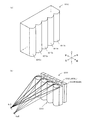
前記表示手段に表示される画像のうち前記三次元表示態様で表示され得る部分の素材となる画像であって、立体視において想定されるN個(Nは、2以上の整数)の視点に各々対応するN個の立体視用素材画像(例えば、左前景用素材画像及び右前景用素材画像)それぞれと、前記表示手段に表示される画像のうち前記通常表示態様で表示され得る部分の素材となる背景用素材画像及び特定素材画像(例えば、エラー用素材画像)と、を合成することにより、N個の元画像(例えば、スケーリング前左目用画像及びスケーリング前右目用画像)を生成することが可能な第1画像生成手段(例えば、図196のステップS5702〜ステップS5705の処理を実行するホスト制御回路7210)と、
前記第1画像生成手段により生成された前記N個の元画像に対してそれぞれスケーリングを行い、スケーリングにより得られる各画像を合成することにより、前記表示手段に表示させるための画像を生成することが可能な第2画像生成手段(例えば、図179のステップS5142〜ステップS5144の処理を実行する表示制御回路7230)と、を備える、
ことを特徴とする遊技機。
(1) An image related to a game is displayed, and a part of the image is displayed in a three-dimensional display mode that allows the player to stereoscopically view the image, while the other part of the image is different from the three-dimensional display mode. A display unit (for example, a display device 8000) capable of displaying in a display mode,
Image generation means capable of generating an image displayed on the display means (for example, a
The image generation means,
Of the images displayed on the display means, the images that are the material of the portion that can be displayed in the three-dimensional display mode, and are each viewed in N (N is an integer of 2 or more) viewpoints assumed in stereoscopic viewing. Corresponding N stereoscopic material images (for example, a left foreground material image and a right foreground material image), and a material of a portion that can be displayed in the normal display mode among the images displayed on the display unit. By combining the background material image and the specific material image (for example, the error material image), the N original images (for example, the pre-scaling left-eye image and the pre-scaling right-eye image) can be generated. Possible first image generation means (for example, a
An image to be displayed on the display unit may be generated by performing scaling on each of the N original images generated by the first image generation unit and synthesizing each image obtained by the scaling. Possible second image generation means (for example, a
A gaming machine characterized by that.
(1)の発明によれば、表示手段は、遊技に関する画像を表示し、該画像の一部を遊技者に対して立体視させ得る三次元表示態様で表示する一方、該画像の他の部分を通常表示態様で表示することが可能である。このような表示手段に表示される画像を生成するに当たっては、表示手段に表示される画像のうち三次元表示態様で表示され得る部分の素材となるN個の立体視用素材画像それぞれと、表示手段に表示される画像のうち通常表示態様で表示され得る部分の素材となる背景用素材画像及び特定素材画像とを合成することにより、N個の元画像が生成される。N個の立体視用素材画像は、それぞれ、立体視において想定されるN個の視点に対応している。そして、N個の元画像が生成されると、該N個の元画像に対してそれぞれスケーリングを行い、スケーリングにより得られる各画像を合成することにより、表示手段に表示させるための画像が生成される。表示手段に表示させるための画像をこのように生成することにより、本発明者は、表示手段に表示される画像のうちの一部の表示態様を立体視に適した表示態様とすることが可能であり、結果として、遊技者に対して所望の立体的画像を認識させることができることを見出した。このようにして、(1)の発明によれば、所望の立体視を実現することが可能である。 According to the invention of (1), the display means displays an image relating to the game and displays a part of the image in a three-dimensional display mode that allows the player to stereoscopically view the image, while the other part of the image is displayed. Can be displayed in a normal display mode. In generating an image displayed on such a display unit, each of N material images for stereoscopic vision, which is a material of a portion that can be displayed in a three-dimensional display mode among the images displayed on the display unit, is displayed. N original images are generated by synthesizing the background material image and the specific material image, which are the materials of the portion that can be displayed in the normal display mode among the images displayed on the means. Each of the N stereoscopic material images corresponds to N viewpoints assumed in stereoscopic viewing. When the N original images are generated, scaling is performed on each of the N original images, and the images obtained by the scaling are combined to generate an image to be displayed on the display means. It By generating the image to be displayed on the display unit in this way, the present inventor can set a part of the display mode of the image displayed on the display unit to a display mode suitable for stereoscopic viewing. As a result, it was found that the player can recognize a desired stereoscopic image. Thus, according to the invention of (1), it is possible to realize a desired stereoscopic vision.
本発明によれば、所望の立体視を実現することができる。 According to the present invention, desired stereoscopic vision can be realized.
[第1実施形態]
以下、本発明の一実施形態に係るパチンコ遊技機(遊技機)の構成及び各種動作について、図面を参照しながら説明する。
[First Embodiment]
Hereinafter, the configuration and various operations of a pachinko gaming machine (gaming machine) according to an embodiment of the present invention will be described with reference to the drawings.
[1.遊技機の構成]
[1−1.外観構成]
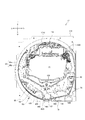
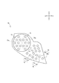
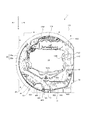
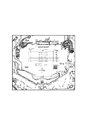
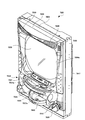
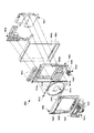
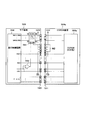
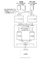
まず、図1〜図8を用いて、パチンコ遊技機1の外観について説明する。図1は、本発明の一実施形態に係るパチンコ遊技機における外観を示す斜視図の一例である。図2は、本発明の一実施形態に係るパチンコ遊技機における外観を示す分解斜視図の一例である。図3は、操作ボタン群の一例を模式的に示す図である。図4は、本発明の一実施形態に係るパチンコ遊技機を背面側から示す斜視図の一例である。図5は、本発明の一実施形態に係るパチンコ遊技機における遊技盤ユニットの外観を示す正面図の一例である。図6は、本発明の一実施形態に係るパチンコ遊技機における遊技盤ユニットの外観斜視図を示す一例である。図7は、本発明の一実施形態に係るパチンコ遊技機における遊技盤ユニットを前方右斜め上から見た分解斜視図を示す一例である。図8は、第1及び第2特別図柄表示部を含むLEDユニットを示す正面図の一例である。また、図面に示されている方向は、正面視における方向である。したがって、例えば図面右方向に「左」と記載されているのは、当該図面が背面図であるため、図面上の「右」が正面視における「左」となる。同様に、図面左方向に「右」と記載されているものも、同様の理由により図面上の「左」が正面視における「右」となる。
[1. Game machine configuration]
[1-1. Appearance configuration]
First, the appearance of the
なお、以下の説明では、特に説明がない限り、パチンコ遊技機1を遊技者から見て、手前側を前側とし、奥側を後側として、前後方向を規定する。また、パチンコ遊技機1を遊技者から見て、左手側を左側とし、右手側を右側として、左右方向を規定する。さらに、正面とは遊技者側から見た場合に視認できる側の面であり、背面とは遊技者の反対側から見た場合に視認できる側の面である。
In the following description, the front and back sides are defined as the front side and the back side as the front side as viewed from the player of the
図1、図2および図4〜図7に示すように、パチンコ遊技機1は、木枠11、ベースドア12、ガラスドア13、皿ユニット14、発射装置15、液晶表示装置16、遊技盤ユニット17、払出ユニット18、及び、基板ユニット19を具備する。
As shown in FIGS. 1, 2 and 4 to 7, the
木枠11は、正面視略矩形状の枠体である。木枠11には、前後方向に貫通する開口21が設けられる。木枠11の開口21には、ベースドア12が嵌め込まれる。ベースドア12は、各種の部材を支持するものである。具体的には、ベースドア12は、裏面側に払出ユニット18及び基板ユニット19を支持すると共に、表面側にガラスドア13や、皿ユニット14、発射装置15、液晶表示装置16及び遊技盤ユニット17を支持する。
The
ガラスドア13は、ベースドア12に対して開閉自在に軸着されるものである。ガラスドア13には、開口22、操作ボタン群66が設けられる。ガラスドア13の開口22には、透過性を有する保護ガラス23が配設される。保護ガラス23は、ガラスドア13がベースドア12に対して閉鎖された状態で後述する遊技盤ユニット17と前後方向に対向するように配置される。また、ガラスドア13の上部には、スピーカ24及びLED25が配設される。スピーカ24は、例えば音声での告知や、演出、エラー報知等を行うものである。LED25は、例えば光での告知や、演出等を行う演出用の発光手段であり、発光演出を実行できればLEDに限られず、例えばランプ等であってもよい。
The
図3に示すように、操作ボタン群66は、メインボタン662とセレクトボタン664とを有する。セレクトボタン664は、上セレクトボタン664a、下セレクトボタン664b、左セレクトボタン664cおよび右セレクトボタン664dを有する。以下において、セレクトボタン664と称するときは、上下左右セレクトボタン664a〜664dの総称を意味する。
As shown in FIG. 3, the
本実施形態のパチンコ遊技機1は、メインボタン662およびセレクトボタン664のうち少なくともいずれか一方または両方を用いて、後述するガイドメニュー画面やホールメニュー画面等で操作を行うことができる。なお、操作ボタン群66を設ける位置は、ガラスドア13に限られず、皿ユニット14、例えば上皿26上等に設けてもよい。
The
皿ユニット14は、上皿26及び下皿27を一体化したユニット体である。皿ユニット14は、ベースドア12の前下部であって、ガラスドア13の下方に配置される。
The
上皿26は、遊技球を貯留するものであって、上皿26に貯留される遊技球は、発射装置15から後述する遊技領域20に向けて発射される。上皿26には、払出口61及び演出ボタン62が設けられる。貸し出される遊技球や賞球として払い出される遊技球は、払出口61から上皿26に払い出される。演出ボタン62は、所謂「CHANCEボタン」や、「プッシュボタン」等と呼ばれるものである。演出ボタン62は、遊技者によって操作される操作機能の他、所定の演出機能を有してもよい。所定の演出機能としては、例えば後述する特別図柄の大当り判定の結果にもとづいて上方に突出するような機能が相当する。
The
下皿27は、主に上皿26から溢れた遊技球を貯留するためのものである。下皿27には、払出口63が設けられる。上皿26から溢れた遊技球は、払出口63から下皿27に払い出される。
The
発射装置15は、上皿26に貯留された遊技球を、遊技領域20に向けて発射するためのものである。発射装置15は、ベースドア12の前右下部であって、皿ユニット14の右下方に配置される。発射装置15は、パネル体31、駆動装置(不図示)及び発射ハンドル32を具備する。
The launching
パネル体31は、発射装置15において皿ユニット14の右下部と一体化されるものである。発射ハンドル32は、パネル体31の表面側に配置される。前記駆動装置は、パネル体31の裏面側に配置され、例えば発射ソレノイド(図示せず)により構成される。こうして、発射装置15において、遊技者によって発射ハンドル32が操作されると、操作に応じた前記駆動装置の動作により遊技球が発射される。
The
液晶表示装置16は、特別図柄の大当り判定(以下、特別図柄の大当り判定を単に「大当り判定」と称することもある)の結果や、遊技に関する各種の演出画像を表示するものである。演出表示装置16の表示領域に表示される前記各種の演出画像には、例えば演出用識別図柄(装飾図柄)や、大当り判定の結果に応じた演出画像、大当り中の演出画像、デモ演出画像、特別図柄の変動表示(可変表示)の保留数等が含まれる。液晶表示装置16(より詳細には、液晶表示装置16の表示領域)は、遊技盤ユニット17の略中央(後述するセンターレール1742の内周側)に配置される。
The liquid
なお、本実施形態では、上記各種の演出画像を表示するものとして一つの液晶表示装置16を備えているが、二つの液晶表示装置を設けて、当該二つの液晶表示装置を用いて演出画像を表示するようにしても良い。
In the present embodiment, one liquid
また、図4に示すように、本実施形態のパチンコ遊技機1は、主制御回路100(後述する図9参照)を有する主制御基板30と、サブ制御回路200(後述する図9参照)を有するサブ制御基板40と、遊技球の払出・発射を制御する払出・発射制御回路300(後述する図9参照)を有する払出・発射制御基板50と、電源を供給する電源供給回路338(後述する図9参照)を有する電源供給ユニット60と、電源スイッチ35と、バックアップクリアスイッチ330(後述する図9参照)とがそれぞれ設けられている。
As shown in FIG. 4, the
本実施形態のパチンコ遊技機1は、パチンコゲームにかかわる各種データが異なる複数の設定値(本実施形態では「1」〜「6」の6段階)が設けられている。設定「6」が遊技者に最も有利であり、設定値の値が小さくなるにつれて遊技者にとっての有利度も段階的に低くなる。
The
主制御基板30を収容する主基板ケース内には、設定値を変更する際に操作される設定スイッチ332、設定値を変更したり確認したりする際に操作される設定キー328、性能表示モニタ334およびエラー報知モニタ336(いずれも後述の図9参照)が収容されている。性能表示モニタ334には、例えば後述する性能表示データや設定値が表示される。エラー報知モニタ336には、例えば後述するエラーコード等が表示される。なお、設定スイッチ332および設定キー328が主制御基板ケース内に収容されているのは、セキュリティ面を考慮して、パチンコ遊技機1の管理責任者(以下、「遊技機管理責任者」と称する)以外の第三者(例えば遊技者)が設定スイッチ332や設定キー328に容易にアクセスできないようにするためである。尚主基板ケース内とは、正に主基板ケースを開放しないと設定スイッチ332または/および設定キー328にアクセスできないものに加え、主基板ケースの設定スイッチ332および設定キー328の対応箇所にのみ切欠きがあり、遊技機管理責任者が管理する鍵を使用してパチンコ遊技機1を設置している島設備から当該パチンコ遊技機1を回動させて背面を露出させたときに、遊技機管理責任者が設定スイッチ332または/および設定キー328にアクセスできるようにされているものも含む。
In the main board case that accommodates the
遊技盤ユニット17は、保護ガラス23の後方に位置するように、ベースドア12の前方に配置される。遊技盤ユニット17の前側面には、発射された遊技球が転動流下可能な遊技領域20が形成される。
The
図5〜図7に示すように、遊技盤ユニット17は、発射された遊技球が転動流下可能な遊技領域20が形成される透明パネル172と、遊技領域20の略中央部に配置されるセンターユニット174と、普通電動役物ユニット400と、アタッカユニット500と、通過ゲート49と、裏ユニット176とを備える。センターユニット174、普通電動役物ユニット400、アタッカユニット500、及び通過ゲート49は、透明パネル172の前方側に設けられる。裏ユニット176は、遊技盤ユニット17を装飾するものであって、透明パネル172の後方側に設けられる。この裏ユニット176は、液晶表示装置16の表示領域の上部に配置される上部役物1000等(図7参照)の各役物を備える。これらの各役物1000は、特別抽選の結果にもとづいて動作可能な演出役物として機能する。
As shown in FIG. 5 to FIG. 7, the
透明パネル172には、後述する液晶表示装置16の表示領域が配置される部位に開口1722が形成されている。図5及び図7に示すように、透明パネル172の前面には、ガイドレール26が設けられるとともに遊技釘等が植設されている。発射装置15から発射された遊技球は、ガイドレール26から遊技領域20に向けて飛び出し、遊技釘等と衝突して進行方向を変えながら遊技領域20の下方に向けて流下する。
An
ガイドレール26は、2つのレール状の部材(以下では、「外レール26a」及び「内レール26b」と称する。)により構成される。遊技領域20は、ガイドレール26によって区画(画定)される。内レール26bは、外レール26aと共に、発射された遊技球を遊技領域20の上部に案内するためのものである。内レール26bは、透明パネル172の左側において外レール26aの内側に配置される。
The
センターユニット174は、透明パネル172の開口1722の上方(液晶表示装置16の表示領域の上方)にセンターレール1742を備えており、正面視で円弧状に形成されている。センターレール1742は、遊技領域20の上部に配置されており、遊技領域20における遊技球の流下領域を、当該センターレール1742の左右に区分けするものである。
The
発射装置15によって発射された遊技球は、センターレール1742の左右に区分けされて遊技領域20を流下し、遊技領域20を流下する遊技球は、遊技盤ユニット17(詳しくは透明パネル172)に植設された遊技釘等との衝突により、進行方向を変えながら下方へ向けて流下する。発射された遊技球は、発射ハンドル52の操作量に応じて流下領域が振り分けられる。具体的には、発射ハンドル52の操作量が小さい場合、発射された遊技球はセンターレール1742の左側領域を流下する。一方、発射ハンドル52の操作量が大きい場合、発射された遊技球はセンターレール1742の右側領域を流下する。なお、センターレール1742の左側領域に遊技球を流下させる打ち方は所謂「左打ち」と呼ばれ、センターレール1742の右側領域に遊技球を流下させる打ち方は所謂「右打ち」と呼ばれ、遊技者によって打ち分け可能とされている。
The game balls launched by the launching
アタッカユニット500は、第1始動口420、大入賞口540及び特別電動役物600を一体化したユニット体である。アタッカユニット500は、遊技領域20内の略右下部であって、通過ゲート49の下方に配置される。
The
大入賞口540は、遊技者に有利な遊技状態である大当り遊技状態の場合に開放可能な部分である。大入賞口540には、カウントスイッチ541が配設される(図9参照)。大入賞口540に遊技球が入賞すると、当該入賞した遊技球がカウントスイッチ541に検知される。カウントスイッチ541に遊技球が検知されると、予め設定された数の遊技球が払出口61から上皿26(又は、払出口63から下皿27)に払い出される。
The special winning
特別電動役物600は、前後方向に進退可能なシャッタ610、及び当該シャッタ610を駆動する大入賞口ソレノイド620(図9参照)を具備する。特別電動役物600は、大入賞口540の上方に配置される。特別電動役物600は、大入賞口ソレノイド620によりシャッタ610が駆動されることによって、大入賞口540への遊技球の入賞を可能(又は容易)とする開放状態と、大入賞口540への遊技球の入賞を不可能(又は困難)とする閉鎖状態と、に移行(駆動)可能に構成される。特別電動役物600(シャッタ610)による開放駆動は、第1始動口420又は後述する第2始動口440に遊技球が入賞したときに行われる大当り判定の結果に基づいて、大当り遊技状態に移行された場合に行われる。なお、第1始動口420又は後述する第2始動口440に遊技球が入賞したときに行われる大当り判定の結果は、第1特別図柄表示部73又は第2特別図柄表示部74において、特別図柄の停止表示態様によって示される。
The special
なお、この明細書において、単に「特別図柄」と称するときは、第1特別図柄および第2特別図柄の両方を意味するものとする。ただし、本実施形態では特別図柄の数が2つ(第1特別図柄、第2特別図柄)であるが、特別図柄の数は1つであっても良い。 In this specification, when simply referred to as "special symbol", it means both the first special symbol and the second special symbol. However, in the present embodiment, the number of special symbols is two (first special symbol, second special symbol), but the number of special symbols may be one.
第1始動口420は、遊技球の入賞(通過)を条件に大当り判定の契機を与えると共に、大当り判定の結果を、液晶表示装置16や、後述する第1特別図柄表示部73に表示させる契機を与えるものである。第1始動口420には、第1始動口スイッチ421が配設される(図9参照)。第1始動口420に遊技球が入賞すると、当該入賞した遊技球が第1始動口スイッチ421に検知される。第1始動口スイッチ421に遊技球が検知されると、パチンコ遊技機1の内部(図9に示すメインCPU101)において大当り判定が行われると共に、予め設定された数の遊技球が払出口61から上皿26に又は払出口63から下皿27に払い出される(排出される)。なお、第1始動口420への遊技球の入賞は、左打ちによって行われる。
The first start opening 420 gives a trigger for a big hit determination on the condition of winning (passing) a game ball, and also causes the result of the big hit determination to be displayed on the liquid
普通電動役物ユニット400は、第2始動口440、アウト口450及び普通電動役物460を一体化したユニット体である。普通電動役物ユニット400は、遊技領域20の略左下部に配置される。第2始動口440とアウト口450とは互いに隣接して配置されており、第2始動口440が正面視で右側に、アウト口450が正面視で左側に配置されている。従来、普通電動役物ユニット400は例えば第1始動口420の下方に配置されるものが多かった。しかし、近年、液晶表示装置16をより大型化することが要求されており、第1始動口420の下方に配置することが困難となっている。そこで本実施形態のパチンコ遊技機1では、遊技領域20の略左下部に普通電動役物ユニット400を配置するようにしている。
The ordinary electric
第2始動口440は、遊技球の入賞(通過)を条件に大当り判定の契機を与えると共に、大当り判定の結果を、液晶表示装置16や、後述する第2特別図柄表示部74に表示させる契機を与えるものである。第2始動口440には、第2始動口スイッチ441が配設される(図9参照)。第2始動口440に遊技球が入賞すると、当該入賞した遊技球が第2始動口スイッチ441に検知される。第2始動口スイッチ441に遊技球が検知されると、パチンコ遊技機1の内部(図9に示すメインCPU101)において大当り判定が行われると共に、予め設定された数の遊技球が、払出口61から上皿に又は払出口63から下皿27に払い出される(排出される)。第2始動口440は、普通電動役物460によって入賞困難性が決定される。なお、第2始動口440への遊技球の入賞は、原則として右打ちによって行われる。
The second starting opening 440 gives a trigger for a big hit determination on the condition of winning (passing) a game ball, and also causes the result of the big hit determination to be displayed on the liquid
普通電動役物460は、右方向に回動可能な羽根部材4620、始動口ソレノイド4630(例えば、図9参照)及び当該始動口ソレノイド4630の動力を羽根部材4620に伝達する動力伝達機構(不図示)を具備する。普通電動役物460は、始動口ソレノイド4630により羽根部材4620が駆動されることによって、遊技球の通過が容易な開放状態と遊技球の通過が困難な閉鎖状態との間で移行(駆動)可能に構成される。羽根部材4620が駆動されているときに当該羽根部材4620の上方を遊技球が通過すると、当該遊技球は、第2始動口440に入賞するか、アウト口450からパチンコ遊技機1の外部に排出される。普通電動役物460(羽根部材4620)による開閉駆動は、普通図柄表示部71において普通図柄が特定の停止表示態様となった場合に、所定の期間及び回数だけ行われる。
The ordinary
通過ゲート49は、遊技球の入賞(通過)を条件に普通図柄判定の契機を与えるものである。通過ゲート49は、センターユニット174の下方右側であって、アタッカユニット500の上方右側に配置される。通過ゲート49には、通過ゲートスイッチ49aが配設される(図9参照)。通過ゲート49に遊技球が通過すると、当該通過した遊技球が通過ゲートスイッチ49aに検知される。通過ゲートスイッチ49aに遊技球が検知されると、パチンコ遊技機1の内部(図2に示すメインCPU101)において普通図柄判定が行われる。なお、通過ゲート49への遊技球の通過は、右打ちによって行われる。
The
アタッカユニット500は、第1始動口420、大入賞口540及び特別電動役物600を一体化したユニット体である。アタッカユニット500は、遊技領域20の略右下部に配置される。アタッカユニット500が遊技領域20の略右下部に配置されるのは、近年、液晶表示装置16をより大型化することが要求されており、アタッカユニット500等の各種部材を遊技領域20に配置するには、かかる大型化された液晶表示装置16を回避する必要があるためである。
The
大入賞口540は、遊技者に有利な遊技状態である大当り遊技状態の場合に開放可能な部分である。大入賞口540には、カウントスイッチ541が配設される(図9参照)。大入賞口540に遊技球が入賞すると、当該入賞した遊技球がカウントスイッチ541に検知される。カウントスイッチ541に遊技球が検知されると、予め設定された数の遊技球が払出口61から上皿26(又は、払出口63から下皿27)に払い出される(排出される)。
The special winning
特別電動役物600は、前後方向に進退可能なシャッタ610、及び当該シャッタ610を駆動する大入賞口ソレノイド620(図9参照)を具備する。特別電動役物600は、大入賞口540の上方に配置される。特別電動役物600は、大入賞口ソレノイド620によりシャッタ610が駆動されることによって、大入賞口540への遊技球の入賞を可能(又は容易)とする開放状態と、大入賞口540への遊技球の入賞を不可能(又は困難)とする閉鎖状態と、に移行(駆動)可能に構成される。特別電動役物600(シャッタ610)による開放駆動は、第1特別図柄表示部73又は第2特別図柄表示部74において特別図柄が特定の停止表示態様となって、大当り遊技状態に移行された場合に行われる。
The special
一般入賞口53・54・55は遊技盤ユニット17の左下部に配置され、一般入賞口56は遊技盤ユニット17の右下部に配置される。また、一般入賞口53・54・55・56には、一般入賞口スイッチ53a・54a・55a・56aが配設される(図9参照)。一般入賞口53・54・55・56に遊技球が入賞すると、当該入賞した遊技球が一般入賞口スイッチ53a・54a・55a・56aに検知される。一般入賞口スイッチ53a・54a・55a・56aに遊技球が検知されると、予め設定された数の遊技球が払出口61から上皿26(又は、払出口63から下皿27)に払い出される(排出される)。
The general winning
なお、本実施形態においては、第1始動口420及び第2始動口440の賞球数は3個、一般入賞口53・54・55・56の賞球数は10個、大入賞口540の賞球数は15個にそれぞれ設定されている。この値(賞球数)は、任意に設計変更可能である。
In addition, in the present embodiment, the number of prize balls of the
アウト口57は、遊技領域20の中央最下部(遊技球の流下方向における最下流位置)に配置される。アウト口57は、発射された遊技球が、いずれの始動口や入賞口にも入賞しなかった場合に、最終的に流入される。
The
LEDユニット70は、遊技盤ユニット17の右下部であって、ガイドレール41の外側に配置される(図5、図6参照)。LEDユニット70は、各種の表示部を一体化したユニット体である。具体的には、LEDユニット70は、前記各種の表示部として、普通図柄表示部71、普通図柄用保留表示部72、第1特別図柄表示部73、第2特別図柄表示部74、第1特別図柄用保留表示部75及び第2特別図柄用保留表示部76を具備する。
The
普通図柄表示部71は、普通図柄ゲームに対する判定(普通図柄判定)の結果を表示するものである。ここで、普通図柄ゲームとは、判定(普通図柄判定)の結果によって普通電動役物460を駆動して開放状態とするか否かを決定するゲームを指す。普通図柄表示部71は、表示LED71a・71bを具備する。表示LED71a・71bは、変動表示(可変表示)の開始条件が成立すると、交互に点灯・消灯を繰り返す変動表示を開始する。表示LED71a・71bの点灯・消灯による組み合わせ(表示パターン)は、普通図柄として表示される。表示LED71a・71bは、変動表示を開始した後、所定の期間経過後に停止表示を行う。
The normal
判定(普通図柄判定)の結果が当り(以下「普通当り」と称する)である場合、表示LED71a・71bの点灯・消灯の組み合わせ(普通図柄)が特定の停止表示態様となる。こうして、普通図柄が特定の停止表示態様で停止表示されると、普通電動役物460を開放状態とすることが決定し、普通電動役物460が所定のパターンで開閉駆動し、第2始動口440への遊技球の入賞困難性が変更される。
When the result of the determination (ordinary symbol determination) is a hit (hereinafter referred to as “ordinary symbol”), the combination of turning on/off the
普通図柄用保留表示部72は、保留されている普通図柄の変動表示の実行回数(以下、「普通図柄の変動表示の保留数」と称する)を表示するものである。普通図柄用保留表示部72は、表示LED72a・72bを具備する。普通図柄用保留表示部72は、表示LED72a・72bの点灯・消灯の組み合わせによって普通図柄の変動表示の保留数を表示する。例えば、普通図柄の変動表示の実行が1回分保留されている場合には、表示LED72aが点灯すると共に、表示LED72bが消灯する。また、普通図柄の変動表示の実行が2回分保留されている場合には、表示LED72aが点灯すると共に、表示LED72bが点灯する。また、普通図柄の変動表示の実行が3回分保留されている場合には、表示LED72aが点滅すると共に、表示LED72bが点灯する。また、普通図柄の変動表示の実行が4回分保留されている場合には、表示LED72aが点滅すると共に、表示LED72bが点滅する。
The normal symbol
第1特別図柄表示部73及び第2特別図柄表示部74は、特別図柄ゲームに対する判定(大当り判定)の結果を表示するものである。ここで、特別図柄ゲームとは、判定(大当り判定)の結果によって遊技状態の移行又は維持を決定するゲームを指す。
The first special
第1特別図柄表示部73は、8個のLEDからなる表示LED群73aを具備する。表示LED群73aは、第1始動口420への遊技球の入賞(始動入賞)を契機として変動表示を行うと共に、当該遊技球の入賞に基づく大当り判定の結果を表示する。表示LED群73aは、変動表示の開始条件が成立すると、8個のLEDがそれぞれ点灯・消灯を繰り返す変動表示を開始する。表示LED群73aにおいて、8個のLEDの点灯・消灯による組み合わせ(表示パターン)は、特別図柄として表示される。表示LED群73aは、変動表示を開始した後、所定の期間経過後に停止表示を行う。
The first special
第1始動口420への遊技球の入賞に基づく大当り判定の結果が大当りである場合、表示LED群73aの8個のLEDの点灯・消灯の組み合わせ(特別図柄)が特定の停止表示態様となる。こうして、特別図柄が特定の停止表示態様で停止表示されると、遊技状態の移行が決定し、シャッタ610が所定のパターンで開閉駆動し、大入賞口540に遊技球が入賞可能な遊技状態となる。なお、以下の説明では、第1始動口420への遊技球の入賞に基づいて第1特別図柄表示部73に変動表示される特別図柄を、第1特別図柄と称する。
When the result of the big hit determination based on the winning of the game ball to the first starting opening 420 is a big hit, the combination (special symbol) of turning on/off the eight LEDs of the
第2特別図柄表示部74は、8個のLEDからなる表示LED群74aを具備する。表示LED群74aは、第2始動口440への遊技球の入賞(始動入賞)を契機として変動表示を行うと共に、当該遊技球の入賞に基づく大当り判定の結果を表示する。表示LED群74aは、変動表示の開始条件が成立すると、8個のLEDがそれぞれ点灯・消灯を繰り返す変動表示を開始する。表示LED群74aにおいて、8個のLEDの点灯・消灯による組み合わせ(表示パターン)は、特別図柄として表示される。表示LED群74aは、変動表示を開始した後、所定の期間経過後に停止表示を行う。
The second special
第2始動口440への遊技球の入賞に基づく大当り判定の結果が大当りである場合、表示LED群74aの8個のLEDの点灯・消灯の組み合わせ(特別図柄)が特定の停止表示態様となる。こうして、特別図柄が特定の停止表示態様で停止表示されると、遊技状態の移行が決定し、シャッタ610が所定のパターンで開閉駆動し、大入賞口540に遊技球が入賞可能な遊技状態となる。なお、以下の説明では、第2始動口440への遊技球の入賞に基づいて第2特別図柄表示部74に変動表示される特別図柄を、第2特別図柄と称する。
When the result of the big hit determination based on the winning of the game ball to the second starting opening 440 is a big hit, the combination (special symbol) of turning on/off the eight LEDs of the
このように、第1特別図柄表示部73及び第2特別図柄表示部74の表示LED群73a・74aにおいて、第1又は第2特別図柄が特定の停止表示態様で停止表示されると、通常の遊技状態(通常遊技状態)から遊技者に有利な状態である大当り遊技状態への移行が決定する。なお、本実施形態において、大当り判定は、第1始動口420への遊技球の入賞に基づく大当り判定と、第2始動口440への遊技球の入賞に基づく大当り判定と、が含まれる。すなわ+ち、大当り判定の結果が大当りである場合には、大入賞口540が開放されるラウンド遊技が所定ラウンド数にわたって実行される大当り遊技状態に移行される。
In this way, in the
第1特別図柄用保留表示部75及び第2特別図柄用保留表示部76は、保留されている特別図柄の変動表示の実行回数(以下、「特別図柄の変動表示の保留数」と称する)を表示するものである。第1特別図柄用保留表示部75は、表示LED75a・75bを具備する。第2特別図柄用保留表示部76は、表示LED76a・76bを具備する。第1特別図柄用保留表示部75及び第2特別図柄用保留表示部76は、表示LED75a・75b及び76a・76bの点灯・消灯によって特別図柄の変動表示の保留数を表示する。表示LED75a・75b及び76a・76bの点灯・消灯の表示態様は、普通図柄用保留表示部72の表示LED72a・72bと同様である。
The first special symbol
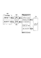
[1−2.電気的構成]
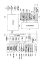
次に、図9を用いて、パチンコ遊技機1の制御回路について説明する。
[1-2. Electrical configuration]
Next, the control circuit of the
図9に示すように、パチンコ遊技機1は、主に、遊技の制御を行う主制御回路100と、遊技の進行に応じた演出の制御を行うサブ制御回路200と、払出・発射制御回路300と、電源供給回路338と、から構成される。
As shown in FIG. 9, the
主制御回路100は、メインCPU101、メインROM102(読み出し専用メモリ)及びメインRAM103(読み書き可能メモリ)等を具備しており、主基板ケース内に収容されている。
The
メインCPU101には、メインROM102や、メインRAM103等が接続される。メインCPU101は、メインROM102に記憶されたプログラムに従って、各種の処理を実行する機能を有する。
A
メインROM102には、メインCPU101によりパチンコ遊技機1の動作を制御するためのプログラムや、各種のテーブル等が記憶されている。
The
メインRAM103は、メインCPU101の一時記憶領域として種々のフラグや変数の値を記憶する機能を有し、無通電状態であっても書き込まれた情報を記憶保持可能である。なお、本実施形態においては、メインCPU101の一時記憶領域としてメインRAM103を用いているが、これに限らず、読み書き可能な記憶媒体であればよい。
The
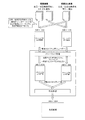
メインRAM103には、特別図柄ゲームの情報が始動記憶として記憶される記憶領域が設けられる。具体的には、メインRAM103には、変動中の第1特別図柄に対応する特別図柄ゲームの情報が始動記憶として記憶される第1特別図柄始動記憶領域(0)と、上限4回分の第1特別図柄に対応する特別図柄ゲームの情報が始動記憶として記憶される第1特別図柄始動記憶領域(1)から第1特別図柄始動記憶領域(4)と、が設けられる。また同様に、メインRAM103には、変動中の第2特別図柄に対応する特別図柄ゲームの情報が始動記憶として記憶される第2特別図柄始動記憶領域(0)と、上限4回分の第2特別図柄に対応する特別図柄ゲームの情報が始動記憶として記憶される第2特別図柄始動記憶領域(1)から第2特別図柄始動記憶領域(4)と、が設けられる。
The
また、主制御回路100は、電源投入時においてリセット信号を生成する初期リセット回路104や、I/Oポート105、コマンド出力ポート106、バックアップコンデンサ107等を具備する。初期リセット回路104は、メインCPU101に接続される。I/Oポート105は、各種のデバイスからの入力信号をメインCPU101に送信したり、メインCPU101からの出力信号を各種の装置に送信したりするものである。コマンド出力ポート106は、メインCPU101からのコマンドをサブ制御回路200に送信するものである。バックアップコンデンサ107は、電断(電源OFF)時において、例えばメインRAM103に対して速やかに電源を供給することにより、メインRAM103に記憶されている各種データを保持するものである。
The
また、主制御回路100には、各種の装置(部材)が接続されている。
Further, various devices (members) are connected to the
例えば、主制御回路100には、普通図柄表示部71や、普通図柄用保留表示部72、第1特別図柄表示部73、第2特別図柄表示部74、第1特別図柄用保留表示部75、第2特別図柄用保留表示部76、普通電動役物460の羽根部材4620を駆動する始動口ソレノイド4630、シャッタ610を駆動する大入賞口ソレノイド620等が接続されている。主制御回路100は、信号を送信することにより、これらの装置(部材)の動作を制御することができる。また、主制御回路100には、ホール係員を呼び出す機能や大当り回数を表示する機能等を有する呼出装置(不図示)や、ホール全体のパチンコ遊技機を管理するホールコンピュータ700にデータ送信するために用いる外部端子板323が接続されている。
For example, in the
また、主制御回路100には、第1始動口スイッチ421や、第2始動口スイッチ441、通過ゲートスイッチ49a、カウントスイッチ541、一般入賞口スイッチ53a・54a・55a・56a、性能表示モニタ334等が接続されている。主制御回路100には、これらの部材で遊技球が検知された場合に、当該部材から所定の検知信号が供給される。また、主制御回路100には、電断時におけるバックアップデータを遊技場の管理者の操作に応じてクリアするバックアップクリアスイッチ330等が接続されている。
In addition, the
さらに、主制御回路100には、設定キー328および設定スイッチ332も接続されている。設定キー328は、後述の設定変更処理や設定確認処理を実行するための契機となる鍵または鍵に類するものである。設定スイッチ332は、押下操作可能であり、後述の設定変更処理の際に、セットされている設定値を変更するためのものである。上述したとおり、設定キー328および設定スイッチ332は、遊技機管理責任者以外の第三者(例えば遊技者)が容易にアクセスできないように主基板ケース内に収容されている。
Further, a setting
また、主制御回路100には、払出・発射制御回路300が接続されている。払出・発射制御回路300には、遊技球の払い出しを行う払出装置340や、遊技球の発射を行う発射装置15、カードユニット360等が接続されている。払出装置340は、払出ユニット18に設けられる。カードユニット360には、球貸し操作パネル370が接続され、当該球貸し操作パネル370への遊技者の操作に応じた信号が供給される。
A payout/
払出・発射制御回路300は、主制御回路100から供給される賞球制御コマンドや、カードユニット360から供給される貸し球制御信号を受け取ると、払出装置340に対して所定の信号を送信し、払出装置340に遊技球を払い出させる制御を行う。また、払出・発射制御回路300は、発射ハンドル32が遊技者によって握持され、かつ、時計回り方向へ回動操作されると、その回動角度(回動量)に応じて発射ソレノイド(図示せず)に電力を供給し、遊技球を発射させる制御を行う。
When the payout/
さらに、コマンド出力ポート106には、サブ制御回路200(コマンド入力ポート208)が接続されている。サブ制御回路200は、主制御回路100から供給される各種のコマンドに応じて、液晶表示装置16における表示制御や、スピーカ24から発生させる音声に関する制御、LED25の光に関する制御等を行う。
Further, the sub-control circuit 200 (command input port 208) is connected to the
なお、本実施形態においては、主制御回路100からサブ制御回路200にコマンドを供給する一方、サブ制御回路200から主制御回路100に信号を供給できないように構成したが、これに限らず、サブ制御回路200から主制御回路100に信号を送信できるように構成してもよい。
In this embodiment, the
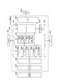
サブ制御回路200は、サブCPU201、プログラムROM202、バックアップメモリとして機能するワークRAM203、表示制御回路204、音声制御回路205、LED制御回路206、役物制御回路207およびコマンド入力ポート208等を具備する。サブ制御回路200は、主制御回路100からの指令に応じて遊技の進行に応じた演出を実行する。また、サブ制御回路200には、演出ボタン62の操作によってON/OFFされる演出ボタンスイッチ621、メインボタン662の操作によってON・OFFされるメインボタンスイッチ6621、および、各セレクトボタン664a〜664dの操作によってON・OFFされるセレクトボタンスイッチ6641a〜6641dが接続されている。なお、実際には、各セレクトボタン664a〜664dに対応するセレクトボタンスイッチ6641a〜6641dが夫々設けられているが、図9では、便宜上、これらをまとめてセレクトボタンスイッチ6641と示している。
The
サブCPU201は、プログラムROM202に記憶されたプログラムに従って、各種の処理を実行する機能を有する。特に、サブCPU201は、主制御回路100から供給される各種のコマンドに従って、サブ制御回路200の制御を行う。
The
プログラムROM202には、サブCPU201によりパチンコ遊技機1の遊技演出を制御するためのプログラムや、各種のテーブル等が記憶されている。
The
なお、本実施形態においては、プログラムやテーブル等が記憶される記憶手段として、メインROM102及びプログラムROM202を用いるように構成したが、これに限らず、制御手段を備えたコンピュータにより読み取り可能な記憶媒体であれば別態様であってもよい。例えば、前記記憶手段として、ハードディスク装置や、CD−ROM及びDVD−ROM、ROMカートリッジ等の記憶媒体を用いてもよい。また、前記プログラムやテーブル等は、予め記録されているものでなくとも、電源投入後にダウンロードされ、ワークRAM203等に記録されるものでもよい。さらに、前記プログラムやテーブル等は、各々異なる記憶媒体に記録されていてもよい。
In the present embodiment, the
ワークRAM203は、サブCPU201の一時記憶領域として種々のフラグや変数の値を記憶する機能を有する。なお、本実施形態においては、サブCPU201の一時記憶領域としてワークRAM203を用いているが、これに限らず、読み書き可能な記憶媒体であればよい。
The
表示制御回路204は、液晶表示装置16における表示制御を行うための回路である。表示制御回路204は、画像データプロセッサ(以下、VDPと称する)や、各種の画像データを生成するためのデータが記憶されている画像データROM、画像データをバッファするフレームバッファ、画像データを画像信号として変換するD/Aコンバータ等を具備する。
The
表示制御回路204は、サブCPU201から供給されるデータに応じて、液晶表示装置16に画像を表示させるための種々の処理を行うことができる。表示制御回路204は、サブCPU201から供給される画像表示命令に応じて、液晶表示装置16に表示させるための画像データを一時的にフレームバッファに格納する。なお、液晶表示装置16に表示させるための画像データには、装飾図柄を示す装飾図柄画像データや、背景画像データ、演出用画像データ等の、遊技に関する各種の画像データが含まれる。
The
そして、表示制御回路204は、所定のタイミングで、フレームバッファに格納された画像データをD/Aコンバータに供給する。D/Aコンバータは、画像データを画像信号として変換し、当該変換した画像信号を所定のタイミングで液晶表示装置16に供給する。液晶表示装置16に画像信号が供給されると、液晶表示装置16に当該画像信号に関する画像が表示される。こうして、表示制御回路204は、液晶表示装置16に遊技に関する画像を表示させる制御を行うことができる。
Then, the
音声制御回路205は、スピーカ24から発生させる音声に関する制御を行うための回路である。音声制御回路205は、音声に関する制御を行う音源ICや、各種の音声データを記憶する音声データROM、音声信号を増幅するための増幅器(以下、AMPと称する)等を具備する。
The
前記音源ICは、スピーカ24から発生させる音声の制御を行う。音源ICは、サブCPU201から供給される音声発生命令に応じて、音声データROMに記憶されている複数の音声データから一つの音声データを選択する。また、音源ICは、選択された音声データを音声データROMから読み出し、音声データを所定の音声信号に変換し、当該変換した音声信号をAMPに供給する。AMPは、音声信号を増幅させ、スピーカ24から音声を発生させる。
The sound source IC controls the sound generated from the
LED制御回路206は、装飾LED等を含むLED25の制御を行うための回路である。LED制御回路206は、LED制御信号を供給するためのドライブ回路や、複数種類のLED装飾パターンが記憶されている装飾データROM等を具備する。
The
役物制御回路207は、各役物の制御を行うための回路である。役物制御回路207は、各役物に対して、駆動信号を供給するための駆動回路や、点灯制御信号を供給するための点灯回路、動作パターンや点灯パターンが記憶されている役物データROM等を有する。
The
また、駆動回路は、サブCPU201から供給される役物作動命令に応じて、役物データROMに記憶されている複数の動作パターンから一つの動作パターンを選択する。そして、選択した動作パターンを役物データROMから読み出し、読み出した動作パターンに対応する駆動信号を供給することにより、各役物の機械的な動作を制御する。また、点灯回路は、サブCPU201から供給される点灯命令に基づいて、役物データROMに記憶されている複数の点灯パターンから一つの点灯パターンを選択する。そして、選択した点灯パターンを役物データROMから読み出し、読み出した点灯パターンに対応する点灯制御信号を供給することにより、各役物の点灯動作を制御する。
Further, the drive circuit selects one operation pattern from a plurality of operation patterns stored in the accessory data ROM in accordance with the accessory operation command supplied from the
コマンド入力ポート208は、主制御回路100送信されたコマンドを受信するものである。
The
払出・発射制御回路300は、パチンコ遊技機1からの賞球や貸球の払い出しを制御するものであり、この払出・発射制御回路300には、遊技球を払い出すための払出装置350、遊技球を発射するための発射装置340、電断時におけるバックアップデータを遊技場の管理者の操作に応じてクリアするバックアップクリアスイッチ330等が接続されている。
The payout/
電源供給回路338は、パチンコ遊技機1で遊技を行うために必要な電源電圧を、主制御回路100、サブ制御回路200、払出・発射制御回路300等に供給するために作成する電源回路である。
The
電源供給回路338には、電源スイッチ35等が接続されている。電源スイッチ35は、パチンコ遊技機1に必要な電源を供給するときにON操作するものである。
The
なお、設定キー328および設定スイッチ332は、上述したように主制御回路100に接続されているが、これに代えて、電源供給回路338に接続されるようにしても良い。この場合であっても、遊技機管理責任者以外の第三者(例えば遊技者)が設定スイッチ332や設定キー328に容易にアクセスできないように、所定のケース内に収容されていることが好ましい。このような場合であっても、所定のケース内とは、正に当該ケースを開放しないと設定スイッチ332や設定キー328にアクセスできないものに加え、上記ケースの設定スイッチ332および設定キー328の対応箇所にのみ切欠きがあり、遊技機管理責任者が管理する鍵を使用してパチンコ遊技機1を設置している島設備から当該パチンコ遊技機1を回動させて背面を露出させたときに、遊技機管理責任者が設定スイッチ332または/および設定キー328にアクセスできるようにされているものも含む。
The setting
ここで、性能表示モニタ334に表示される表示内容について説明する。性能表示モニタ334には、メインCPU101の制御により性能表示データが表示される。性能表示データは、例えば、所定数(例えば60000発)の遊技球の発射に対して大当り遊技状態以外で払い出された遊技球の割合を示すデータであり、ベース値とも呼ばれる。
Here, the display contents displayed on the performance display monitor 334 will be described. Performance display data is displayed on the performance display monitor 334 under the control of the
払出・発射制御回路300は、過去の遊技履歴に基づいてベース値を集計し、集計結果をメインRAM103の作業領域のうち後述する特定作業領域に記憶する。この特定作業領域については後述するが、後述のバックアップクリア処理が行われてもデータがクリアされない領域である。なお、ベース値の集計は、所定の操作が行われたことに基づいて行われるようにしても良いし、常に集計を行って性能表示モニタ334にベース値が常時表示されるようにしても良い。
The payout/
払出・発射制御回路300は、初期電源投入(パチンコ遊技機1が製造されたのち初めての電源投入)から現在までの全遊技履歴に基づいて全ベース値の集計を実行する全履歴集計手段と、設定値毎の過去の遊技履歴に基づいて設定値別ベース値の集計を実行する設定値別履歴集計手段とを備える。
The payout/
例えば遊技機管理責任者等によって全ベース値の表示操作が行われると、全履歴集計手段は、上記の全ベース値の集計を実行する。全履歴集計手段により集計された全ベース値は、メインCPU101によって性能表示モニタ334に表示される。また、設定値別ベース値の表示操作が行われると、設定値別履歴集計手段は、設定値別ベース値の集計を実行する。設定値別履歴集計手段により集計された設定値別ベース値は、メインCPU101によって性能表示モニタ334に表示される。
For example, when the display operation of all the base values is performed by the gaming machine manager or the like, the all history totaling means performs the totalization of all the base values. All the base values totaled by the total history totaling means are displayed on the performance display monitor 334 by the
設定値別履歴集計手段は、要求(操作)に応じて、任意の設定値についてのベース値のみを集計することもできる。この場合、セットされている設定値についてのベース値だけでなく、セットされている設定値以外の他の設定値についてのベース値を集計することもできる。したがって、メインCPU101は、後述する設定変更処理を実行することなく、他の設定値についてのベース値を性能表示モニタ334に表示することができる。
The set value-based history totalizing means can also total only the base values for arbitrary set values in response to a request (operation). In this case, not only the base values for the set setting values but also the base values for other setting values other than the set setting values can be aggregated. Therefore, the
なお、メインCPU101は、例えば遊技機管理責任者等による操作に応じて、全履歴集計手段により集計された全ベース値と、設定値別履歴集計手段により集計された設定値別ベース値との両方を性能表示モニタ334に表示することもできるし、これらのうちいずれか一方のみを選択的に性能表示モニタ334に表示することもできる。
In addition, the
また、メインCPU101は、特定の設定値のベース値のみを性能表示モニタ334に表示しても良いし、全設定値のベース値を一覧で表示しても良い。また、全ベース値と設定値別ベース値との両方を一覧で表示しても良い。全設定値のベース値を一覧で表示する場合や、全ベース値と設定値別ベース値との両方を一覧で表示する場合には、性能表示モニタ334と他の表示手段との両方を使って表示するようにしても良い。
Further, the
また、メインCPU101は、全履歴集計手段と設定値別履歴集計手段とを備えるが、これらに加えてまたは設定値別履歴集計手段に代えて、後述する設定変更処理が実行されてから現在までの遊技履歴に基づいて設定変更後ベース値を集計する設定変更後履歴集計手段を備えるようにしても良い。この場合、メインCPU101は、設定変更後ベース値の表示操作に基づいて設定変更後の設定値別ベース値を性能表示モニタ334に表示することができる。
Further, the
このように、全ベース値と、設定値別ベース値または/および設定変更後の設定値別ベース値とのうち全部または一部が性能表示モニタ334に表示されるようにすることで、パチンコ遊技機1における過去の遊技履歴に基づく情報を容易に確認することが可能となる。
In this way, by displaying all or a part of all the base values and the base value for each set value or/and the base value for each set value after the setting change on the
なお、本実施例ではベース値を性能表示モニタ334に表示するようにしたが、遊技球の総払出数に対し、特別電動役物(大入賞口)、普通電動役物への入球により払い出された遊技球数(役物による払出)の割合を表示するようにしてもよい。また、それは総発射数に対する表示でもよく、さらに特別電動役物(大入賞口)により払い出された遊技球数の割合を表示するものでもよい。またそれらを設定別に表示してもよい。
In the present embodiment, the base value is displayed on the
また、エラー報知モニタ336には、後述するエラーコードが表示される。このエラー報知モニタ336には、エラーコードの他に、後述する設定変更処理中であることを示す設定変更中コード、後述設定確認処理中であることを示す設定確認中コード等を表示することもできる。なお、設定変更中において、特別図柄表示装置において通常では表示することのない図柄(設定変更図柄)を表示するようにしてもよい。 Further, the error notification monitor 336 displays an error code described later. In addition to the error code, the error notification monitor 336 may also display a setting change code indicating that the setting change processing described later is being performed, a setting confirmation code indicating that the setting confirmation processing is being performed later, and the like. it can. During the setting change, the special symbol display device may display a symbol (setting change symbol) which is not normally displayed.
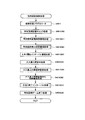
[2.機能フロー]
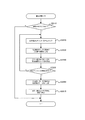
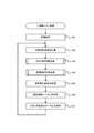
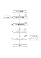
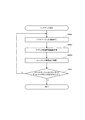
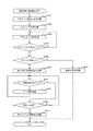
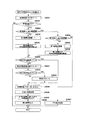
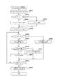
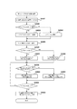
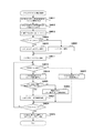
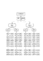
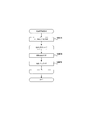
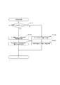
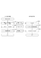
次に、図10を用いて、本発明の一実施形態に係るパチンコ遊技機の機能フローについて説明する。図10は、本発明の一実施形態に係るパチンコ遊技機の機能フローを示す図である。
[2. Function flow]
Next, a functional flow of the pachinko gaming machine according to the embodiment of the present invention will be described with reference to FIG. FIG. 10 is a diagram showing a functional flow of the pachinko gaming machine according to the embodiment of the present invention.
図10に示すように、パチンコゲームは、ユーザの操作により遊技球が発射され、その遊技球が各種入賞した場合に遊技球の払出制御処理が行われるゲームである。また、パチンコゲームには、特別図柄を用いる特別図柄ゲーム、普通図柄を用いる普通図柄ゲームが含まれる。 As shown in FIG. 10, the pachinko game is a game in which a game ball is shot by a user's operation and a payout control process of the game ball is performed when the game ball receives various prizes. Further, the pachinko game includes a special symbol game using a special symbol and a normal symbol game using a normal symbol.
特別図柄ゲームにおいて「大当り」となったときや、普通図柄ゲームにおいて「普通当り」となったときには、相対的に、遊技球が入賞する可能性が増大し、遊技球の払出制御処理が行われ易くなる。 When it becomes a "big hit" in the special symbol game, or when it becomes a "normal hit" in the normal symbol game, the possibility that the game ball will win is relatively increased, and the payout control process of the game ball is performed. It will be easier.
また、各種入賞には、特別図柄ゲームにおいて特別図柄の変動表示が行われるための一つの条件である特別図柄始動入賞や、普通図柄ゲームにおいて普通図柄の変動表示が行われるための一つの条件である普通図柄始動入賞も含まれる。 In addition, in various prizes, a special symbol starting prize which is one condition for performing variable display of special symbols in the special symbol game, and one condition for performing variable display of ordinary symbols in the ordinary symbol game It also includes a normal symbol starting prize.
以下、特別図柄ゲーム及び普通図柄ゲームの処理フローの概要を説明する。特別図柄ゲーム及び普通図柄ゲームは、メインCPU101により制御処理として実行される。
Hereinafter, the outline of the processing flow of the special symbol game and the normal symbol game will be described. The special symbol game and the normal symbol game are executed as control processing by the
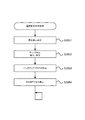
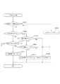
(1)特別図柄ゲームにおいて特別図柄始動入賞があった場合には、各種カウンタ(例えば大当り判定用カウンタや図柄決定用カウンタ)からそれぞれ各種乱数値(例えば大当り判定用乱数値や図柄決定用乱数値)が抽出(取得)され、抽出された各乱数値が記憶される(図10に示す特別図柄ゲーム中の特別図柄始動入賞処理のフロー参照)。 (1) When there is a special symbol start prize in the special symbol game, various random number values (for example, a big hit determination random number value and a symbol determination random number value) from various counters (for example, a big hit determination counter or a symbol determination counter). ) Is extracted (acquired), and each extracted random number value is stored (see the flow of the special symbol start winning process in the special symbol game shown in FIG. 10).
また、図10に示すように、特別図柄ゲーム中の特別図柄制御処理では、最初に、特別図柄の変動表示を開始する条件が成立したか否かが判別される。この判別処理では、特別図柄始動入賞によって乱数値等の各種データが記憶されているか否かを参照し、乱数値等の各種データが記憶されていることを一つの条件として、特別図柄の変動表示を開始する条件が成立したと判別する。 Further, as shown in FIG. 10, in the special symbol control process during the special symbol game, first, it is determined whether or not the condition for starting the variable display of the special symbol is satisfied. In this determination process, referring to whether or not various data such as a random number value is stored due to a special symbol starting winning, one condition that various data such as a random number value is stored is a variable display of the special symbol. It is determined that the condition for starting is satisfied.
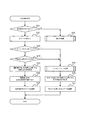
次いで、特別図柄の変動表示を開始する場合、大当り判定用カウンタから抽出された大当り判定用乱数値が参照され、「大当り」とするか否かの大当り判定が行われる。その後、停止図柄決定処理が行われる。この処理では、図柄決定用カウンタから抽出された図柄決定用乱数値と、上述した大当り判定の結果とが参照され、停止表示させる特別図柄を決定する。 Next, when the variable display of the special symbol is started, the random number value for jackpot determination extracted from the jackpot determination counter is referred to, and a jackpot determination as to whether or not to make a "jackpot" is performed. Then, a stop symbol determination process is performed. In this process, the random number for symbol determination extracted from the symbol determination counter and the result of the above-described jackpot determination are referred to, and the special symbol to be stopped and displayed is determined.
次いで、変動パターン決定処理が行われる。この処理では、変動パターン決定用カウンタから乱数値が抽出され、その乱数値と、上述した大当り判定の結果と、上述した停止表示させる特別図柄とが参照され、特別図柄の変動パターン(可変表示パターン)を決定する。 Then, the variation pattern determination process is performed. In this process, a random number value is extracted from the variation pattern determination counter, the random number value, the result of the above-described jackpot determination, and the above-mentioned special symbol to be stopped and displayed are referred to, and the variation pattern of the special symbol (variable display pattern ) Is determined.
次いで、演出パターン決定処理が行われる。この処理では、演出パターン決定用カウンタから乱数値が抽出され、その乱数値と、上述した大当り判定の結果と、上述した停止表示させる特別図柄と、上述した特別図柄の変動パターンとが参照され、特別図柄の変動表示に伴って実行する演出パターンを決定する。 Next, an effect pattern determination process is performed. In this process, a random number value is extracted from the effect pattern determination counter, the random number value, the result of the jackpot determination described above, the special symbol to be stopped and displayed, and the variation pattern of the special symbol described above are referred to, The effect pattern to be executed along with the variable display of the special symbol is determined.
次いで、決定された大当り判定の結果、停止表示させる特別図柄、特別図柄の変動パターン、及び、特別図柄の変動表示に伴う演出パターンが参照され、特別図柄の変動表示の制御を行う変動表示制御処理、及び、所定の演出を行う演出制御処理が実行される。 Then, as a result of the determined jackpot, the special symbol to be stopped and displayed, the variation pattern of the special symbol, and the effect pattern accompanying the variation display of the special symbol are referred to, and the variable display control process for controlling the variable display of the special symbol is performed. , And an effect control process for performing a predetermined effect is executed.
そして、変動表示制御処理及び演出表示制御処理が終了すると、「大当り」となるか否かが判定される。この判定処理において、「大当り」となったと判定されると、大当り遊技状態を行う大当り遊技状態制御処理が実行される。なお、大当り遊技状態では、上述した各種入賞の可能性が増大する。一方、「大当り」とならなかったと判定されると、大当り遊技状態制御処理が実行されない。 Then, when the variable display control process and the effect display control process are completed, it is determined whether or not a “big hit” will occur. In this determination process, when it is determined that the "big hit" is reached, a big hit game state control process for performing a big hit game state is executed. In the jackpot gaming state, the above-mentioned various winning possibilities increase. On the other hand, if it is determined that the "big hit" has not occurred, the big hit game state control process is not executed.
「大当り」とならなかったと判定された場合、又は、大当り遊技状態制御処理が終了した場合には、遊技状態を移行させるための遊技状態移行制御処理が行われる。この遊技状態移行制御処理では、大当り遊技状態とは異なる通常時の遊技状態の管理が行われる。 When it is determined that the "big hit" is not reached, or when the big hit game state control process is finished, a game state transition control process for shifting the game state is performed. In this game state transition control process, a normal game state different from the big hit game state is managed.
通常時の遊技状態としては、例えば、上述した大当り判定において、所定の確率で「大当り」と判定される遊技状態(以下、「通常遊技状態」という)や、「大当り」と判定される確率が通常遊技状態よりも増大する遊技状態(以下、「高確率遊技状態」という)や、後述する普通当り判定の結果として特別図柄始動入賞が得られやすくなる遊技状態(以下、「時短遊技状態」という)などが挙げられる。その後、再度、特別図柄の変動表示を開始させるか否かの判別処理を行い、その後は、上述した特別図柄制御処理の各種処理が繰り返される。 As the game state at the time of normal operation, for example, in the above-described big hit determination, a game state determined to be a “big hit” with a predetermined probability (hereinafter referred to as “normal game state”) or a probability determined to be a “big hit” A gaming state that increases more than the normal gaming state (hereinafter referred to as "high-probability gaming state"), or a gaming state in which a special symbol start winning is easily obtained as a result of an ordinary hit determination described later (hereinafter referred to as "time saving gaming state") ) And the like. After that, again, the determination process of whether to start the variable display of the special symbol is performed, and thereafter, the various processes of the special symbol control process described above are repeated.
なお、本実施形態のパチンコ遊技機において、特別図柄の変動表示中に遊技球が始動入賞した場合には、該始動入賞時に抽出される各種データ(大当り判定用乱数値、図柄決定用乱数値等)が、特別図柄の変動表示を開始する条件が成立するまで記憶される。このように、特別図柄の変動表示を開始する条件が成立するまで各種データ(例えば大当り判定用乱数値等)を記憶することを「保留」といい、保留される各種データを始動記憶という。 In the pachinko gaming machine of the present embodiment, when the game ball wins during the variable display of the special symbol, various data extracted at the time of winning the start (random number value for jackpot determination, random number value for symbol determination, etc.) ) Is stored until the condition for starting the variable display of the special symbol is satisfied. In this way, storing various data (for example, a big hit determination random number value) until the condition for starting the variable display of the special symbol is called "holding", and the various data held is called starting storage.
すなわち、特別図柄の変動表示中に遊技球が始動入賞した場合には、該始動入賞に対応する特別図柄の変動表示の実行が保留され、現在実行されている特別図柄の変動表示終了後に保留されている特別図柄の変動表示が順に開始される。以下では、保留されている特別図柄についての各種データを「保留球」ともいう。 That is, when the game ball wins during the variable display of the special symbol, the execution of the variable display of the special symbol corresponding to the starting prize is suspended, and is suspended after the end of the variable display of the currently executed special symbol. The variable display of the special symbols being displayed is sequentially started. In the following, various types of data regarding special symbols that are being held are also referred to as “holding balls”.
また、本実施形態のパチンコ遊技機では、後述するように、2種類の特別図柄始動入賞(第1始動口入賞及び第2始動口入賞)を設け、各特別図柄始動入賞に対して最大4個まで特別図柄の変動表示の実行を保留することができる。すなわち、本実施形態では、第1特別図柄の4個と第2特別図柄の4個とで合計最大8個まで、特別図柄の変動表示の実行を保留することができる。 Further, in the pachinko gaming machine of the present embodiment, as will be described later, two types of special symbol start prizes (first start mouth prize and second start mouth prize) are provided, and a maximum of four for each special symbol start prize. Until the execution of variable display of special symbols can be suspended. That is, in the present embodiment, it is possible to suspend the execution of the variable display of the special symbols, up to a total of 8 of the first special symbols and the second special symbols.
なお、図10には示されていないが、本実施形態のパチンコ遊技機1は、上述した保留球の情報に基づいて保留球の当落(「大当り」当選の有無)を判定し、さらに、その判定結果に基づいて所定の演出を行う機能、すなわち先読み演出機能を備えている。
Although not shown in FIG. 10, the
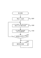
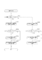
(2)普通図柄ゲームにおいて普通図柄始動入賞があった場合には、普通当り判定用カウンタから乱数値が抽出され、その乱数値が記憶される(図10に示す普通図柄ゲーム中の普通図柄始動入賞処理のフロー参照)。 (2) If there is a normal symbol start winning in the normal symbol game, a random number value is extracted from the normal hit determination counter, and the random number value is stored (normal symbol start in the normal symbol game shown in FIG. 10). Refer to the winning process flow).
また、図10に示すように、普通図柄ゲーム中の普通図柄制御処理では、最初に、普通図柄の変動表示を開始する条件が成立したか否かが判別される。この判別処理では、普通図柄始動入賞によって乱数値が記憶されているか否かが参照され、乱数値が記憶されていることを一つの条件として、普通図柄の変動表示を開始する条件が成立したと判別する。 Further, as shown in FIG. 10, in the normal symbol control process during the normal symbol game, first, it is determined whether or not the condition for starting the variable display of the normal symbol is satisfied. In this determination process, it is referred to whether or not a random number value is stored by the normal symbol start winning, and one condition that the random number value is stored is that the condition for starting the variable display of the normal symbol is satisfied. To determine.
次いで、普通図柄の変動表示を開始する場合、普通当り判定用カウンタから抽出された乱数値が参照され、「普通当り」とするか否かの普通当り判定が行われる。その後、変動パターン決定処理が行われる。この処理では、普通当り判定の結果が参照され、普通図柄の変動パターンを決定する。 Next, when the variable display of the normal symbol is started, the random number value extracted from the normal hit determination counter is referred to, and the normal hit determination of whether or not the "normal hit" is performed is performed. After that, the variation pattern determination process is performed. In this process, the result of the normal hit determination is referred to, and the variation pattern of the normal symbol is determined.
次いで、決定された普通当り判定の結果、及び、普通図柄の変動パターンが参照され、普通図柄の変動表示の制御を行う変動表示制御処理、及び、所定の演出を行う演出制御処理が実行される。 Then, the result of the determined normal hit determination, and the variation pattern of the ordinary symbol is referred to, and the variable display control process for controlling the variable display of the ordinary symbol, and the effect control process for performing a predetermined effect are executed. ..
変動表示制御処理及び演出表示制御処理が終了すると、「普通当り」となるか否かが判定される。この判定処理において、「普通当り」となると判定されると、普通当り遊技を行う普通当り遊技制御処理が実行される。 When the variable display control process and the effect display control process are completed, it is determined whether or not the "normal hit" is achieved. In this determination process, when it is determined that the "normal hit", the normal hit game control process for playing the normal hit game is executed.
普通当り遊技制御処理では、上述した各種入賞の可能性、特に、特別図柄ゲームにおける遊技球の特別図柄始動入賞の可能性が増大する。一方、「普通当り」とならないと判定されると、普通当り遊技制御処理が実行されない。その後、再度、普通図柄の変動表示を開始させるか否かの判別処理を行い、その後は、上述した普通図柄制御処理の各種処理が繰り返される。 In the normal hit game control process, the possibility of the various prizes described above, particularly the possibility of the special symbol starting prize of the game ball in the special symbol game increases. On the other hand, if it is determined that the "normal hit" is not achieved, the normal hit game control process is not executed. After that, again, the determination process of whether to start the variable display of the normal symbol is performed, and thereafter, the various processes of the above-mentioned normal symbol control process are repeated.
上述のように、パチンコゲームでは、特別図柄ゲームにおいて「大当り」となるか否か、遊技状態の移行状況、普通図柄ゲームにおいて「普通当り」となるか否か等の条件により、遊技球の払出制御処理の行われ易さが変化する。 As described above, in the pachinko game, the payout of the game ball is performed according to conditions such as whether or not a "big hit" occurs in the special symbol game, the transition state of the game state, and whether or not the "normal hit" occurs in the ordinary symbol game The ease with which control processing is performed changes.
なお、本実施形態において、各種の乱数値の抽出方式としては、メインCPU101によりプログラムを実行することによって所定の範囲(幅)内で乱数値を生成するソフト乱数方式を用いる。しかしながら、本発明はこれに限定されず、例えば、パチンコ遊技機が、所定周期で乱数が更新される乱数発生器を備える場合には、その乱数発生器におけるカウンタ(いわゆる、リングカウンタ)から乱数値を抽出するハード乱数方式を、上述した各種乱数値の抽出方式として採用してもよい。
In the present embodiment, as a method for extracting various random number values, a soft random number method that generates a random number value within a predetermined range (width) by executing a program by the
なお、ハード乱数方式を用いる場合は、所定周期とは異なるタイミングで、乱数値の初期値を決定することによって、所定周期で同じ乱数値が抽出されることを防止することができる。 In the case of using the hard random number method, it is possible to prevent the same random number value from being extracted in the predetermined cycle by determining the initial value of the random number value at a timing different from the predetermined cycle.
[3.パチンコ遊技機の基本仕様]
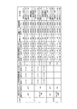
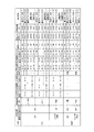
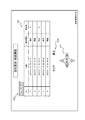
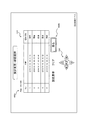
次に、図11〜図14を用いて、パチンコ遊技機1の基本仕様について説明する。図11はパチンコ遊技機1の大当りの確率を示すテーブルの一例を示す図であり、図12は、特別図柄の大当り判定の結果が大当りであるときの当り種別(以下「メイン図柄」と称する)の選択率についての一例を示す図であり、図13はメインROM102に記憶される特別図柄の変動時間(可変表示時間)決定テーブルの一例を示す図である。図14は、サブ制御回路200のプログラムROM202に記憶される装飾図柄決定テーブルの一例を示す図である。なお、以下の説明において、図11〜図14に示されていないメインCPU101およびメインRAM103の用語を用いているが、これらは図9に示されている。
[3. Basic specifications of pachinko machines]
Next, the basic specifications of the
図11に示される大当りの確率について説明するにあたり、先ず、パチンコ遊技機1における大当りについて簡単に説明する。
In explaining the jackpot probability shown in FIG. 11, first, the jackpot in the
メインCPU101は、第1始動口420(例えば図5参照)への遊技球の入賞を検出すると、大当り判定用カウンタから第1特別図柄の大当り判定用乱数を抽出し、メインRAM103に記憶される第1特別図柄大当り乱数判定テーブル(図示せず)を参照して、抽出された大当り判定用乱数についての大当り判定(以下、「第1特別図柄の大当り判定」と称する)を行う。なお、第1特別図柄の大当り判定用乱数の抽出は、大当り遊技状態に制御されているときであっても行われる。
When the
同様に、メインCPU101は、第2始動口440(例えば図5参照)への遊技球の入賞を検出すると、大当り判定用カウンタから第2特別図柄の大当り判定用乱数を抽出し、メインRAM103に記憶される第2特別図柄大当り乱数判定テーブル(図示せず)を参照して、抽出された大当り判定用乱数についての大当り判定(以下、「第2特別図柄の大当り判定」と称する)を行う。なお、第2特別図柄の大当り判定用乱数の抽出は、大当たり遊技状態に制御されているときであっても行われる。
Similarly, the
第1特別図柄の大当り判定が行われると、「大当り」および「ハズレ」のいずれかに決定される。また、第2特別図柄の大当り判定が行われると、第1特別図柄の大当り判定と同様に、「大当り」および「ハズレ」のいずれかに決定される。メインRAM103に記憶される第1特別図柄の大当り乱数判定テーブルおよび第2特別図柄の大当り乱数判定テーブルには、それぞれ、確変フラグの値(「0(=オフ)」又は「1(=オン)」)毎に、「大当り」又は「ハズレ」に決定される大当り判定用乱数の範囲(幅)と、それに対応する判定値データ(「大当り判定値データ」及び「ハズレ判定値データ」)との関係が規定されている。
When the big hit determination of the first special symbol is performed, it is determined to be either "big hit" or "miss". Further, when the big hit determination of the second special symbol is performed, like the big hit determination of the first special symbol, it is determined to be either “big hit” or “miss”. The jackpot random number determination table of the first special symbol and the jackpot random number determination table of the second special symbol stored in the
本実施形態では、第1特別図柄および第2特別図柄ともに、総乱数は65536である。すなわち、上記の大当り判定用乱数は0〜65535の範囲(幅)で発生する。この範囲は固定値として設定されている。大当り確率は、大当り判定用乱数の範囲に対する大当り判定値データの数によって定められる。なお、大当り判定用乱数の範囲(幅)は、適宜変更することができる。 In the present embodiment, the total random number is 65536 for both the first special symbol and the second special symbol. That is, the big hit determination random numbers are generated in the range (width) of 0 to 65535. This range is set as a fixed value. The jackpot probability is determined by the number of jackpot determination value data for the range of random numbers for jackpot determination. The range (width) of the random numbers for jackpot determination can be changed as appropriate.
なお、確変フラグは、メインRAM103に格納される管理フラグの一つであり、遊技状態が「高確率遊技状態」であるか否かを管理するためのフラグである。遊技状態が「高確率遊技状態」である場合には、確変フラグは「1」となり、「低確率遊技状態」である場合には、確変フラグは「0」となる。
The probability variation flag is one of the management flags stored in the
また、時短フラグは、メインRAM103に格納される管理フラグの一つであり、遊技状態が「時短遊技状態」であるか否かを管理するためのフラグである。遊技状態が「時短遊技状態」である場合には、時短フラグは「1」となり、「非時短遊技状態」である場合には、時短フラグは「0」となる。なお、時短遊技状態では、時短回数もメインCPU101によって管理されており、特別図柄が1回変動する毎に、時短回数が1減算される。
The time saving flag is one of the management flags stored in the
なお、時短フラグがON設定される時短遊技状態では、非時短遊技状態と比べて、普通当り判定において普通当りと判別される確率(普通当り確率)が高められる。そのため、時短遊技状態では、非時短遊技状態と比べて、普通電動役物46が閉鎖状態から開放状態になる頻度、すなわち第2始動口440への遊技球の入賞頻度が高められる。ただし、時短遊技状態において、非時短遊技状態と比べて普通当り確率を高めることに代えて、例えば、普通当り抽選の実行頻度を高める(普通図柄の変動時間が短くする)ことで、普通電動役物46が閉鎖状態から開放状態になる頻度を高めるようにしても良いし、普通電動役物46の開放態様を変えることで当該普通電動役物46に入賞しやすくしても良い。また、上記の三態様のうち二態様または三態様を組み合わせても良い。 In the time saving game state in which the time saving flag is set to ON, the probability of being judged as a normal hit in the normal hit determination (ordinary hit probability) is increased as compared with the non-time saving game state. Therefore, in the time saving game state, as compared with the non-time saving game state, the frequency of the normal electric auditors object 46 changing from the closed state to the open state, that is, the winning frequency of the game ball to the second starting opening 440 is increased. However, in the time saving game state, instead of increasing the normal hit probability compared to the non-time saving game state, for example, by increasing the execution frequency of the normal hit lottery (shortening the variation time of the normal symbol), the normal electric role The frequency of the object 46 changing from the closed state to the open state may be increased, or the ordinary electric auditors product 46 may be changed in the opening mode to facilitate winning the ordinary electric auditors product 46. Moreover, you may combine 2 aspects or 3 aspects among said 3 aspects.
本実施形態のパチンコ遊技機1では、確変フラグおよび時短フラグのいずれもがOFFの通常遊技状態と、確変フラグON且つ時短フラグONの確変時短遊技状態と、確変フラグOFF且つ時短フラグONの時短遊技状態とのうち、いずれかの遊技状態にメインCPU101により制御されるように構成されている。
In the
メインCPU101は、第1始動口420(例えば図5参照)への遊技球の入賞を検出して第1特別図柄の大当り判定用乱数を抽出すると、当該抽出した第1特別図柄の大当り判定用乱数値を、第1特別図柄の変動表示が開始されるまで始動記憶として保留する。そして、第1特別図柄の変動表示を開始するときに、第1特別図柄の大当り判定を行い、大当りであるかハズレであるかを決定する。
When the
メインCPU101は、第2始動口440(例えば図5参照)への遊技球の入賞を検出して第2特別図柄の大当り判定用乱数を抽出すると、当該抽出した第2特別図柄の大当り判定用乱数値を、第2特別図柄の変動表示が開始されるまで始動記憶として保留する。そして、第2特別図柄の変動表示を開始するときに、第2特別図柄の大当り判定を行い、大当りであるかハズレであるかを決定する。
When the
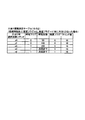
[3−1.大当り確率]
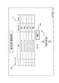
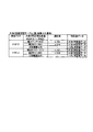
図11に示されるように、第1特別図柄の大当り判定においては、セットされている設定値に応じて大当り確率が異なっている。大当り確率が相対的に低い低確率遊技状態(確変フラグOFF)であるとき、設定値毎の大当り確率は、設定1で約300分の1、設定2で約290分の1、設定3で約280分の1、設定4で約270分の1、設定5で約260分の1、設定6で約250分の1となっている。また、大当り確率が相対的に高い高確率遊技状態(確変フラグON)であるとき、設定値毎の大当り確率は、設定1で約30分の1、設定2で約29分の1、設定3で約28分の1、設定4で約27分の1、設定5で約26分の1、設定6で約25分の1となっている。
[3-1. Jackpot probability]
As shown in FIG. 11, in the jackpot determination of the first special symbol, the jackpot probability is different depending on the set value being set. When the jackpot probability is relatively low and the gaming state is low (probability variation flag OFF), the jackpot probability for each set value is approximately 1/300 in setting 1, approximately 1/290 in setting 2, and approximately 3 in setting 3. The value is 1/280, the setting 4 is about 1/270, the setting 5 is about 260/, and the
すなわち、上述したとおり、本実施形態では大当り判定用乱数の範囲(幅)が0〜65535の範囲に固定値として設定されているため、第1特別図柄の大当り判定値データの数を設定値に応じて変えることで、設定値に応じて大当り確率を異ならせている。例えば、第1特別図柄における低確率遊技状態では、固定値である大当り判定用乱数の範囲(0〜65535)に対して、大当り判定値データの数を、設定1で218個、設定2で226個、設定3で234個、設定4で243個、設定5で252個、設定6で262個とすることで、設定値に応じて大当り確率を異ならせている。また、高確率遊技状態における大当り判定値データの数は、設定1で21個、設定2で22個、設定3で23個、設定4で24個、設定5で25個、設定6で26個となっている。
That is, as described above, in the present embodiment, since the range (width) of the big hit determination random number is set as a fixed value in the range of 0 to 65535, the number of big hit determination value data of the first special symbol is set to the set value. Depending on the set value, the jackpot probability is changed according to the set value. For example, in the low probability game state in the first special symbol, the number of big hit determination value data is 218 in the
また、第2特別図柄の大当り判定においても、セットされている設定値に応じて大当り確率が異なっている。大当り確率が相対的に低い低確率遊技状態(確変フラグOFF)であるとき、設定値毎の大当り確率は、設定1で300分の1、設定2で290分の1、設定3で280分の1、設定4で270分の1、設定5で260分の1、設定6で250分の1となっている。また、大当り確率が相対的に高い高確率遊技状態(確変フラグON)であるとき、設定値毎の大当り確率は、設定1で30分の1、設定2で29分の1、設定3で28分の1、設定4で27分の1、設定5で26分の1、設定6で25分の1となっている。 Further, also in the jackpot determination of the second special symbol, the jackpot probability is different depending on the set value that is set. When the probability of jackpot is relatively low (probability variation flag OFF), the jackpot probability for each set value is 1/300 in setting 1, 1/190 in setting 2, and 280 in setting 3 1, setting 4 is 1/270, setting 5 is 1/260, and setting 6 is 1/250. When the high-probability game state is relatively high in probability of jackpot (probability change flag ON), the jackpot probability for each set value is 1/30 in setting 1, 1/29 in setting 2, and 28 in setting 3. 1/27, setting 4/27, setting 5/26, and setting 6/25.
すなわち、第2特別図柄の大当り確率についても、大当り判定値データの数を設定値に応じて変えることで、設定値に応じて大当り確率を異ならせている。例えば、第2特別図柄における低確率遊技状態では、固定値である大当り判定用乱数の範囲(0〜65535)に対して、大当り判定値データの数を、設定1で218個、設定2で226個、設定3で234個、設定4で243個、設定5で252個、設定6で262個とすることで、設定値に応じて大当り確率を異ならせている。また、高確率遊技状態における大当り判定値データの数についても、設定1で21個、設定2で22個、設定3で23個、設定4で24個、設定5で25個、設定6で26個となっている。
That is, as for the jackpot probability of the second special symbol, the jackpot probability is changed according to the set value by changing the number of jackpot determination value data according to the set value. For example, in the low-probability game state in the second special symbol, the number of big hit determination value data is 218 in the
なお、第1特別図柄の大当り判定と第2特別図柄の大当り判定とでは、設定に応じて定められる大当り確率が同じである。すなわち、設定値が同じであれば、第1特別図柄の大当り判定における大当り確率と、第2特別図柄の大当り判定における大当り確率とが同じである。例えば設定3であれば、第1特別図柄の大当り判定における大当り確率は低確率遊技状態で280分の1(高確率遊技状態で28分の1)であり、この大当り確率は、第2特別図柄の大当り判定における大当り確率(低確率遊技状態で280分の1、高確率遊技状態で28分の1)と同じである。 In addition, the big hit determination of the first special symbol and the big hit determination of the second special symbol have the same big hit probability determined according to the setting. That is, if the setting values are the same, the big hit probability in the big hit judgment of the first special symbol and the big hit probability in the big hit judgment of the second special symbol are the same. For example, if setting 3, the jackpot probability in the jackpot determination of the first special symbol is 1/280 in the low-probability gaming state (1/28 in the high-probability gaming state), and this jackpot probability is the second special symbol. It is the same as the jackpot probability in the jackpot determination (1/280 in the low-probability gaming state, 1/28 in the high-probability gaming state).
本実施形態では、設定値が設定1〜設定6の6段階であるが、必ずしも6段階である必要はなく、複数段階であれば任意に定めることができる。 In the present embodiment, the setting value has six levels of setting 1 to setting 6, but the setting value does not necessarily have to be 6 levels, and can be arbitrarily set as long as it has a plurality of levels.
また、本実施形態では、設定値が異なると大当り確率も異なるように構成しているが、これに限られず、複数の設定値で共通の大当り確率となるようにしても良い。例えば、設定1と設定2とで共通の大当り確率(第1の確率)とし、設定3と設定4とで共通の大当り確率(第1の確率よりも高い第2の確率)とし、設定5と設定6とで共通の大当り確率(第2の確率よりも高い第3の確率)となるようにしても良い。 Further, in the present embodiment, the big hit probability is different when the set value is different, but the present invention is not limited to this, and a plurality of set values may have a common big hit probability. For example, setting 1 and setting 2 have a common jackpot probability (first probability), setting 3 and setting 4 have a common jackpot probability (second probability higher than the first probability), and setting 5 The setting 6 may have a common jackpot probability (a third probability higher than the second probability).
また、本実施形態では、メインCPU101により発生される大当り判定用乱数の範囲(幅)が0〜65535の範囲に固定値として設定されており、固定値であるこの大当り判定用乱数の範囲に対して、大当り判定値データの数を設定値に応じて変えることで、設定値毎に大当り確率を異ならせているが、設定値毎に大当り確率を異ならせる手法はこれに限られず、大当り判定値データの数を全設定共通とし、総乱数としての大当り判定用乱数の範囲(幅)を設定値に応じて変えることで、設定値に応じて大当り確率を異ならせるようにしても良い。例えば、大当り判定値データの数を全設定共通の218個とし、大当り判定用乱数の範囲(幅)を、設定1で0〜65535の範囲(大当り確率が約300分の1)、設定2で0〜63219の範囲(大当り確率が290分の1)、設定3で0〜61039の範囲(大当り確率が280分の1)、設定4で0〜58859の範囲(大当り確率が270分の1)、設定5で0〜56679の範囲(大当り確率が260分の1)、設定6で0〜54499の範囲(大当り確率が250分の1)とし、メインCPU101が設定値に応じた範囲で大当り判定用乱数を発生させることで、設定値に応じて大当り確率を変えることができる。しかも、この手法によれば、分子(大当り判定値データの数)よりも桁数が多い分母(大当り判定用乱数の範囲)を変えることで大当り確率を変えることになるため、大当り判定用乱数の範囲を固定値として大当り判定値データの数を設定値に応じて変える手法と比べて、設定値毎の大当り確率を細かく設定することが可能となる。
Further, in the present embodiment, the range (width) of the big hit determination random number generated by the
なお、上記では、大当り判定値データの数を全設定共通とし、総乱数としての大当り判定用乱数の範囲(幅)を設定値に応じて変えているが、大当り判定値データの数を全設定共通とすることは必ずしも必須ではない。例えば、設定1では、大当り判定値データの数218個、大当り判定用乱数の範囲(幅)を0〜65535の範囲(大当り確率が約300分の1)とし、設定2では、大当り判定値データの数219個、大当り判定用乱数の範囲(幅)を0〜63509の範囲(大当り確率が約290分の1)とし、設定3では、大当り判定値データの数220個、大当り判定用乱数の範囲(幅)を0〜61599の範囲(大当り確率が約280分の1)とし、設定4では、大当り判定値データの数221個、大当り判定用乱数の範囲(幅)を0〜59669の範囲(大当り確率が約270分の1)とし、設定5では、大当り判定値データの数222個、大当り判定用乱数の範囲(幅)を0〜57719の範囲(大当り確率が約260分の1)とし、設定6では、大当り判定値データの数223個、大当り判定用乱数の範囲(幅)を0〜55749の範囲(大当り確率が約250分の1)としたように、大当り判定値データおよび大当り判定用乱数の範囲(幅)の両方を設定値に応じて変えた場合であっても、大当り判定用乱数の範囲を固定値として大当り判定値データの数を設定値に応じて変える手法と比べて、設定値毎の大当り確率を細かく設定することが可能となる。
In the above, the number of big hit judgment value data is common to all settings, and the range (width) of the big hit judgment random number as a total random number is changed according to the set value. Commonality is not always essential. For example, in setting 1, the number of big hit judgment value data is 218, and the range (width) of the big hit judgment random number is in the range of 0 to 65535 (big hit probability is about 1/300), and in setting 2, big hit judgment value data 219, the range (width) of the big hit determination random number is in the range of 0 to 63509 (the big hit probability is about 1/290), and in the
なお、メインCPU101は、上記の総乱数としての大当り判定用乱数の範囲(幅)を設定値に応じて変えた場合には、後述するステップS72やステップS82の設定チェック処理(図31参照)において、設定値データが「0」〜「5」の範囲内であるか否かの判別に加えてまたはこれに代えて、例えば、総乱数としての大当り判定用乱数の範囲(幅)が設定値に応じた範囲であるか否か、または/および、大当り判定値データの数が設定値に規定された数であるか否か等をチェックするようにしても良い。そして、当該チェックで正常でない(例えば、総乱数としての大当り判定用乱数の範囲(幅)または/および大当り判定値データの数が設定値に応じた範囲外)と判別された場合(後述するステップS721におけるNOに相当する場合)には、メインCPU101は、遊技許可フラグをOFFにし(後述するステップS722)、遊技を進行させることが不可能となる。
When the range (width) of the big hit determination random number as the total random number is changed according to the set value, the
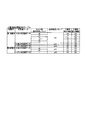
[3−2.大当り振分け]
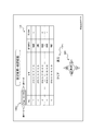
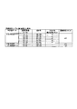
次に、図12を参照して、特別図柄の大当り判定の結果が大当りであるときの大当り振分け、すなわち、特別図柄の停止図柄(メイン図柄)の選択率について説明する。図12に示される例では、メイン図柄の振分は全設定共通となっている。なお、図12に示されるテーブルの内容はメインROM102に記憶されている。
[3-2. Jackpot distribution]
Next, with reference to FIG. 12, a jackpot distribution when the result of the jackpot determination of the special symbol is a big hit, that is, the selection rate of the stop symbol (main symbol) of the special symbol will be described. In the example shown in FIG. 12, the distribution of the main symbols is common to all settings. The contents of the table shown in FIG. 12 are stored in the
図12に示されるように、第1特別図柄の大当り判定の結果が大当りであるとき、メインCPU101は、抽出した図柄決定用乱数に基づいて、メイン図柄を、特図1−1(振分確率25.0%)、特図1−2(振分確率25.0%)、特図1−3(振分確率25.0%)、および特図1−4(振分確率25.0%)のうちいずれかに決定する。特図1−1は、ラウンド数4、確変フラグOFF、時短回数100回の大当りである。特図1−2は、ラウンド数4、確変フラグON、次回の大当り遊技状態が実行されるまで時短が継続する(時短フラグは次回の大当り遊技状態が開始されたときにOFFに設定される)大当りである。特図1−3は、ラウンド数10、確変フラグOFF、時短回数100回の大当りである。特図1−4は、ラウンド数10、確変フラグON、次回の大当り遊技状態が実行されるまで時短が継続する大当りである。第1特別図柄の大当り判定の結果が大当りであるとき、メインCPU101は、第1特別図柄を、後述する図13を参照して決定される変動時間にわたって変動表示したのち、上記決定されたメイン図柄で停止させる制御を実行する。
As shown in FIG. 12, when the result of the big hit determination of the first special symbol is a big hit, the
なお、本実施形態では、特別図柄の大当り判定の結果が大当りであるとき、所定の条件が成立すると(本実施形態では、特図1−2や特図1−4のように確変フラグONとなる大当りであると)、大当り遊技状態が終了したのち、次回の大当り遊技状態が開始されるまで高確率遊技状態が継続する所謂「確変ループ機」と呼ばれるものである。このような確変ループ機では、高確率遊技状態における特別図柄の大当り判定の結果が大当りであって、所定の条件が成立すると、大当り遊技状態が終了したのち、再び、次回の大当り遊技状態が開始されるまで高確率遊技状態が継続する。そして、高確率遊技状態における特別図柄の大当り判定の結果が大当りであって、所定の条件が成立しなければ(本実施形態では、特図1−1や特図1−3のように確変フラグONとならない大当りであると)、大当り遊技状態が終了したのち、高確率遊技状態に制御されずに低確率遊技状態に制御される。 In the present embodiment, when the result of the big hit determination of the special symbol is a big hit, when a predetermined condition is satisfied (in the present embodiment, the probability variation flag is ON as in special figures 1-2 and 1-4). It is a so-called "probability variation loop machine" in which the high-probability game state continues until the next big-hit game state is started after the big-hit game state ends. In such a probability variation loop machine, the result of the big hit judgment of the special symbol in the high-probability game state is a big hit, and if the predetermined condition is satisfied, the big hit game state ends again and the next big hit game state starts again. The high probability game state continues until it is played. And the result of the big hit determination of the special symbol in the high-probability game state is a big hit, and if the predetermined condition is not satisfied (in the present embodiment, the probability change flag as in special figures 1-1 and 1-3). If it is a big hit that does not turn on), after the big hit game state ends, it is controlled to a low probability game state without being controlled to a high probability game state.
第2特別図柄の大当り判定の結果が大当りであるとき、メインCPU101は、抽出した図柄決定用乱数に基づいて、メイン図柄を、特図2−1(振分確率50.0%)または特図2−2(振分確率50.0%)に決定する。特図2−1は、ラウンド数10、確変フラグOFF、時短回数100回の大当りである。特図2−2は、ラウンド数10、確変フラグON、次回の大当り遊技状態が実行されるまで時短が継続する大当りである。第2特別図柄の大当り判定の結果が大当りであるとき、メインCPU101は、第2特別図柄を、後述する図13を参照して決定される変動時間にわたって変動表示したのち、上記決定されたメイン図柄で停止させる制御を実行する。
When the result of the big hit determination of the second special symbol is a big hit, the
なお、特別図柄の大当り判定の結果がハズレであるとき、メインCPU101は、ハズレ図柄を決定し、当該決定されたハズレ図柄で特別図柄を停止させる制御を実行する。
When the result of the jackpot determination of the special symbol is a loss, the
また、ラウンド数とは、大当り遊技状態において実行されるラウンド遊技のラウンド数である。また、確変フラグがONであれば大当り遊技状態が終了したのちの遊技状態が高確率遊技状態(確変フラグがONに設定される遊技状態)に制御され、確変フラグがOFFであれば大当り遊技状態が終了したのちの遊技状態が低確率遊技状態(確変フラグがOFFに設定される遊技状態)に制御される。以下において、ラウンド数4、確変フラグOFF、時短回数100回の大当り(例えば、特図1−1の大当り)を「4R通常大当り」と称し、ラウンド数4、確変フラグON、次回の大当たり遊技が実行されるまで時短が継続する大当り(例えば、特図1−2の大当り)を「4R確変大当り」と称し、ラウンド数10、確変フラグOFF、時短回数100回の大当り(例えば、特図1−3、特図2−1の大当り)を「10R通常大当り」と称し、ラウンド数10、確変フラグON、次回の大当たり遊技が実行されるまで時短が継続する大当り(例えば、特図1−4、特図2−2の大当り)を「10R確変大当り」と称する。
Further, the number of rounds is the number of rounds of the round game executed in the big hit game state. Also, if the probability variation flag is ON, the gaming state after the jackpot gaming state is finished is controlled to a high-probability game state (a gaming state in which the probability variation flag is set to ON), and if the probability variation flag is OFF, the jackpot gaming state. The game state after the end is controlled to a low-probability game state (a game state in which the probability variation flag is set to OFF). In the following, the number of
また、本実施形態では、大当り判定の結果が大当りであるときは、常に時短フラグがONに設定されるようになっているが、必ずしもこれに限られず、抽出した図柄決定用乱数に基づいて決定されるメイン図柄に応じて、時短フラグをONに設定するかOFFに設定するかを決定するようにしても良い。 Further, in the present embodiment, when the result of the big hit determination is a big hit, the time saving flag is always set to ON, but the present invention is not limited to this, and it is determined based on the extracted random number for symbol determination. It may be determined whether to set the time saving flag to ON or OFF according to the main symbol to be performed.
[3−3.特別図柄の変動時間]
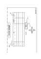
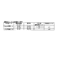
次に、図13を参照して、特別図柄の変動時間が決定されるまでの流れについて説明する。特別図柄の変動時間は、特別図柄の変動パターンと対応しているため、メインCPU101は、特別図柄の変動時間と特別図柄の変動パターンとを同時に決定することとなる。また、特別図柄の変動パターンは、サブ制御回路200(サブCPU201)により液晶表示装置16(例えば図5参照)に表示される演出内容(例えば装飾図柄の変動パターン)とも対応している。本実施形態のパチンコ遊技機1では、決定される特別図柄の変動パターンが(すなわち変動時間や演出内容についても)設定値に応じて異なりうるように構成されている。なお、図13に示されるテーブルの内容はメインROM102に記憶されている。また、特別図柄の保留個数に応じてリーチ演出の実行確率を変えたり、特別図柄の保留個数が多くなるにつれて通常変動における変動時間が短くなるものもあるが、図13ではこれらを省略している。
[3-3. Special symbol variation time]
Next, with reference to FIG. 13, a flow until the variation time of the special symbol is determined will be described. Since the variation time of the special symbol corresponds to the variation pattern of the special symbol, the
図13に示されるように、メインCPU101は、第1特別図柄の大当り判定の結果にもとづいて第1特別図柄の変動時間を決定し、第2特別図柄の大当り判定の結果にもとづいて第2特別図柄の変動時間を決定する。
As shown in FIG. 13, the
図13に示されるように、本実施形態では、第1特別図柄と第2特別図柄とで共通のテーブルを用いて特別図柄の変動時間が決定されるようになっている。ただし、これに代えて、第1特別図柄と第2特別図柄とで別のテーブルを用いて特別図柄の変動時間が決定されるようにしても良い。 As shown in FIG. 13, in the present embodiment, the variation time of the special symbol is determined by using a table common to the first special symbol and the second special symbol. However, instead of this, the variable time of the special symbol may be determined using different tables for the first special symbol and the second special symbol.
また、特別図柄の変動時間決定テーブルは、特別図柄の大当り判定の結果と、遊技状態と、リーチ判定用乱数範囲と、特別図柄の大当り判定の結果が大当りであるときのメイン図柄と、演出選択用乱数範囲と、変動パターン(可変表示パターン)と、変動パターン指定コマンドと、変動時間と、演出内容との関係を規定している。ただし、特別図柄の変動時間を決定するにあたり、確変時短遊技状態と時短遊技状態とは識別されない。また、特別図柄の変動時間を決定する際のリーチ判定用乱数範囲と演出選択用乱数範囲とについては、設定値に応じて異なる乱数範囲が設定されている。 In addition, the variation time determination table of the special symbol, the result of the special symbol big hit determination, the game state, the random number range for reach determination, the main symbol when the result of the special symbol big hit determination is a big hit, and the production selection It defines the relationship among the random number range for use, the variation pattern (variable display pattern), the variation pattern designation command, the variation time, and the effect contents. However, in determining the variation time of the special symbol, the probability variation short time gaming state and short time gaming state are not distinguished. Further, for the reach determination random number range and the effect selection random number range when determining the variation time of the special symbol, different random number ranges are set according to the set values.
リーチ判定用乱数範囲は、特別図柄の大当り判定の結果がハズレである場合に、設定値毎に、リーチ演出を実行するか否かの決定に供される乱数である。メインCPU101は、第1始動口420や第2始動口440(いずれも例えば図5参照)に遊技球が入賞したときに、リーチ判定用カウンタからリーチ判定用乱数を抽出し、当該抽出したリーチ判定用乱数をメインRAM103に格納する。上述したとおり、メインCPU101は、特別図柄の変動表示を開始するときに大当り判定用乱数値を用いて大当り判定を行うが、この大当り判定の結果がハズレであるときに、メインRAM103に格納されたリーチ判定用乱数を用いてリーチ演出を実行するか否かを決定する。本実施形態では、リーチ判定用カウンタから抽出されるリーチ判定用乱数値が0〜249の範囲に設定されているが、この範囲は適宜変更することができる。
The reach determination random number range is a random number provided for determining whether or not to execute the reach effect for each set value when the result of the special symbol big hit determination is a loss. The
例えば、通常遊技状態(確変フラグOFF且つ時短フラグOFF)における特別図柄の大当り判定の結果がハズレの場合、リーチ演出を実行する旨が決定されるリーチ判定用乱数範囲は、設定1・2では0〜25に規定されており、設定3・4では0〜26に規定されており、設定5・6では0〜27に規定されている。また、確変時短遊技状態(確変フラグON且つ時短フラグON)における特別図柄の大当り判定の結果がハズレの場合には、リーチ演出を実行する旨が決定されるリーチ判定用乱数範囲は、設定1・2では0〜10に規定されており、設定3・4では0〜11に規定されており、設定5・6では0〜12に規定されている。
For example, if the result of the big hit determination of the special symbol in the normal game state (probability variation flag OFF and time saving flag OFF) is a loss, the reach determination random number range for determining that the reach effect is executed is 0 in the setting 1.2. -25, the
このように、本実施形態のパチンコ遊技機1における特別図柄の大当り判定の結果がハズレの場合、リーチ演出は、設定1・2よりも設定3・4の方が実行されやすく、さらに、設定3・4よりも設定5・6の方が実行されやすくなっている。すなわち、設定値に応じてリーチ演出の実行頻度が異なっており、設定値がより高いほどリーチ演出の実行頻度が高くなる。
In this way, when the result of the big hit determination of the special symbol in the
なお、本実施形態では、リーチ演出を実行するか否かの決定に際し、リーチ判定用乱数範囲は、設定1と設定2とで共通し、設定3と設定4とで共通し、設定5と設定6とで共通しているが、これに限られず、全ての設定で異なるようにしても良い。 In the present embodiment, when determining whether or not the reach effect is executed, the reach determination random number range is common to setting 1 and setting 2, common to setting 3 and setting 4, and setting 5 and setting. However, the present invention is not limited to this and may be different for all settings.
また、上述したリーチ演出を実行するか否かの決定は、特別図柄の大当り判定の結果がハズレである場合についての説明であるが、特別図柄の大当り判定の結果が大当りである場合、メインCPU101は、リーチ判定用カウンタから抽出されたリーチ判定用乱数の値がいずれであるかにかかわらずリーチ演出を実行する旨を決定する。
Further, the determination as to whether or not to execute the reach effect described above is the case where the result of the big hit determination of the special symbol is loss, but when the result of the big hit determination of the special symbol is the big hit, the
演出選択用乱数範囲は、設定値毎に、特別図柄の変動時間の決定に供される乱数である。メインCPU101は、第1始動口420や第2始動口440(いずれも例えば図5参照)に遊技球が入賞したときに、演出選択用カウンタから演出選択用乱数を抽出し、当該抽出した演出選択用乱数をメインRAM103に格納する。メインCPU101は、遊技状態と、リーチ演出を実行するか否かの決定(特別図柄の大当り判定の結果がハズレである場合のみ)の結果とに応じて、メインRAM103に格納された演出選択用乱数を用いて特別図柄の変動時間を決定する。本実施形態では、演出選択用カウンタから抽出される演出選択用乱数値が0〜99の範囲に設定されているが、この範囲は適宜変更することができる。なお、メインCPU101は、特別図柄の大当り判定の結果が大当りである場合には、遊技状態に応じて、メインRAM103に格納された演出選択用乱数を用いて特別図柄の変動時間を決定する。
The effect selection random number range is a random number provided for determining the variation time of the special symbol for each set value. The
具体的には、通常遊技状態(確変フラグOFF且つ時短フラグOFF)における特別図柄の大当り判定の結果がハズレであって且つリーチ演出を実行する旨が決定された場合の特別図柄の変動時間は、次のように決定される。すなわち、特別図柄の変動時間が20000msec(通常中ノーマルリーチ)に決定される演出選択用乱数範囲は、設定1・2では0〜57に規定されており、設定3・4では0〜58に規定されており、設定5・6では0〜59に規定されている。また、特別図柄の変動時間が30000msec(通常中スーパーリーチA)に決定される演出選択用乱数範囲は、設定1・2では58〜89に規定されており、設定3・4では59〜89に規定されており、設定5・6では60〜89に規定されている。さらに、特別図柄の変動時間が40000msec(通常中スーパーリーチB)に決定される演出選択用乱数範囲は、設定1〜6共通で90〜99に規定されている。
Specifically, the variation time of the special symbol when the result of the big hit determination of the special symbol in the normal gaming state (probability change flag OFF and time saving flag OFF) is a loss and it is determined to execute the reach effect, It is decided as follows. That is, the random number range for effect selection in which the variation time of the special symbol is set to 20000 msec (normal reach during normal operation) is defined as 0 to 57 in setting 1 and 2, and is set to 0 to 58 in setting 3 and 4. The
また、通常遊技状態(確変フラグOFF且つ時短フラグOFF)における特別図柄の大当り判定の結果がハズレであって且つリーチ演出を実行しない旨が決定された場合の特別図柄の変動時間は、次のように決定される。すなわち、特別図柄の変動時間が10000msec(通常変動A)に決定される演出選択用乱数範囲は、設定1・2では0〜51に規定されており、設定3・4では0〜50に規定されており、設定5・6では0〜49に規定されている。また、特別図柄の変動時間が5000msec(通常変動B)に決定される演出選択用乱数範囲は、設定1・2では52〜99に規定されており、設定3・4では51〜99に規定されており、設定5・6では50〜99に規定されている。
In addition, the variation time of the special symbol when the result of the big hit determination of the special symbol in the normal game state (probability change flag OFF and time saving flag OFF) is a loss and it is determined that the reach effect is not executed, is as follows. Is decided. That is, the random number range for effect selection in which the variation time of the special symbol is set to 10000 msec (normal variation A) is defined as 0 to 51 in the
また、確変時短遊技状態(確変フラグON且つ時短フラグON)や通常時短遊技状態(確変フラグOFF且つ時短フラグON)における特別図柄の大当り判定の結果がハズレであって且つリーチ演出を実行する旨が決定された場合の特別図柄の変動時間は、次のように決定される。すなわち、特別図柄の変動時間が25000msec(時短中ノーマルリーチ)に決定される演出選択用乱数範囲は、設定1・2では0〜57に規定されており、設定3・4では0〜58に規定されており、設定5・6では0〜59に規定されている。また、特別図柄の変動時間が35000msec(時短中スーパーリーチA)に決定される演出選択用乱数範囲は、設定1・2では58〜89に規定されており、設定3・4では59〜89に規定されており、設定5・6では60〜89に規定されている。さらに、特別図柄の変動時間が45000msec(時短中スーパーリーチB)に決定される演出選択用乱数範囲は、設定1〜6共通で90〜99に規定されている。
In addition, the probability of the special symbol big hit judgment in the probability variation short time gaming state (probability variation flag ON and time saving flag ON) or the normal time shortening gaming state (probability variation flag OFF and time saving flag ON) is missing and the reach effect is executed. The variation time of the special symbol when determined is determined as follows. That is, the random number range for effect selection in which the variation time of the special symbol is determined to be 25000 msec (normal reach in time saving) is defined as 0 to 57 in setting 1 and 2 and 0 to 58 in setting 3 and 4. The
また、確変時短遊技状態(確変フラグON且つ時短フラグON)や通常時短遊技状態(確変フラグOFF且つ時短フラグON)における特別図柄の大当り判定の結果がハズレであって且つリーチ演出を実行しない旨が決定された場合の特別図柄の変動時間は、次のように決定される。すなわち、特別図柄の変動時間が4000msec(短縮変動A)に決定される演出選択用乱数範囲は、設定1・2では0〜51に規定されており、設定3・4では0〜50に規定されており、設定5・6では0〜49に規定されている。また、特別図柄の変動時間が2000msec(短縮変動B)に決定される演出選択用乱数範囲は、設定1・2では52〜99に規定されており、設定3・4では51〜99に規定されており、設定5・6では50〜99に規定されている。
In addition, the probability that the special symbol big hit judgment in the probability variation short time gaming state (probability variation flag ON and time saving flag ON) or the normal time shortening gaming state (probability variation flag OFF and time saving flag ON) is a loss and that the reach effect is not executed The variation time of the special symbol when determined is determined as follows. That is, the random number range for effect selection in which the variation time of the special symbol is determined to be 4000 msec (shortening variation A) is defined as 0 to 51 in the
なお、メイン図柄は、特別図柄の大当り判定の結果が大当りであるときに決定されるものであるため、特別図柄の大当り判定の結果がハズレであるときは、特別図柄の変動時間の決定とはかかわらない。 Since the main symbol is decided when the result of the big hit judgment of the special symbol is a big hit, when the result of the big hit judgment of the special symbol is lost, what is the determination of the variation time of the special symbol? not involved.
通常遊技状態(確変フラグOFF且つ時短フラグOFF)における特別図柄の大当り判定の結果が大当りである場合の特別図柄の変動時間は、全てのメイン図柄について共通で、次のように決定される。すなわち、特別図柄の変動時間が20000msec(通常中ノーマルリーチ)に決定される演出選択用乱数範囲は、設定1・2では0〜1に規定されており、設定3・4では0〜2に規定されており、設定5・6では0〜3に規定されている。また、特別図柄の変動時間が30000msec(通常中スーパーリーチA)に決定される演出選択用乱数範囲は、設定1・2では2〜49に規定されており、設定3・4では3〜49に規定されており、設定5・6では4〜49に規定されている。さらに、特別図柄の変動時間が40000msec(通常中スーパーリーチB)に決定される演出選択用乱数範囲は、設定1〜6共通で90〜99に規定されている。
The variation time of the special symbol when the result of the big symbol determination of the special symbol in the normal game state (probability change flag OFF and time saving flag OFF) is a big hit is common to all the main symbols and is determined as follows. That is, the random number range for effect selection in which the variation time of the special symbol is set to 20000 msec (normal reach during normal operation) is defined as 0 to 1 in the
また、確変時短遊技状態(確変フラグON且つ時短フラグON)や通常時短遊技状態(確変フラグOFF且つ時短フラグON)における特別図柄の大当り判定の結果が大当りである場合の特別図柄の変動時間は、全てのメイン図柄について共通で、次のように決定される。すなわち、特別図柄の変動時間が25000msec(時短中ノーマルリーチ)に決定される演出選択用乱数範囲は、設定1・2では0〜1に規定されており、設定3・4では0〜2に規定されており、設定5・6では0〜3に規定されている。また、特別図柄の変動時間が35000msec(時短中スーパーリーチA)に決定される演出選択用乱数範囲は、設定1・2では2〜49に規定されており、設定3・4では3〜49に規定されており、設定5・6では4〜49に規定されている。さらに、特別図柄の変動時間が45000msec(時短中スーパーリーチB)に決定される演出選択用乱数範囲は、設定1〜6共通で50〜99に規定されている。
In addition, the variation time of the special symbol when the result of the big hit determination of the special symbol in the probability variation short time gaming state (probability variation flag ON and time saving flag ON) or the normal time shortening game state (probability variation flag OFF and time saving flag ON) is a big hit, It is common to all main symbols and is determined as follows. That is, the random number range for effect selection, in which the variation time of the special symbol is determined to be 25000 msec (normal reach during saving time), is defined as 0 to 1 in
このように、本実施形態のパチンコ遊技機1において、遊技状態と、特別図柄の大当り判定の結果と、リーチ演出を実行するか否かの決定の結果とが同じである限り、特別図柄の変動時間は、設定1・2よりも設定3・4の方が短い変動時間に決定されやすく、さらに、設定3・4よりも設定5・6の方が短い変動時間に決定されやすくなっている。そのため、設定値がより高いほど特別図柄の変動時間の平均が短くなり、単位時間あたりの特別図柄の変動回数(すなわち抽選回数)が多くなる。ひいては、単位時間で見たときの大当り遊技状態の実行回数が多くなる期待度が高く、また、単位時間内に大当り遊技状態が実行される確率も高くなり、設定値が高いほど、遊技者にとって有利なゲームの実行が可能となる。
In this way, in the
なお、本実施形態では、特別図柄の変動時間の決定に際し、演出選択用乱数範囲は、設定1と設定2とで共通し、設定3と設定4とで共通し、設定5と設定6とで共通しているが、これに限られず、全ての設定値で異なるようにしても良い。 In the present embodiment, when determining the variation time of the special symbol, the random number range for effect selection is common to setting 1 and setting 2, common to setting 3 and setting 4, and setting 5 and setting 6. Although it is common, the present invention is not limited to this and may be different for all setting values.
また、特別図柄の大当り判定の結果が大当りである場合の特別図柄の変動時間は、全てのメイン図柄について共通で決定されるようにしているが、これに限られず、メイン図柄に応じて特別図柄の変動時間が異なるように構成しても良い。 In addition, the variation time of the special symbol when the result of the special symbol big hit judgment is a big hit is set to be common to all the main symbols, but it is not limited to this, and the special symbol is determined according to the main symbol. It may be configured such that the fluctuation times of the above are different.
変動パターンは、変動時間および演出内容を表すデータである。例えば、変動パターン「02H」は、変動時間40000msecの通常中スーパーリーチBを表す。 The fluctuation pattern is data representing the fluctuation time and the effect contents. For example, the fluctuation pattern “02H” represents the normal medium super reach B having a fluctuation time of 40,000 msec.
変動パターン指定コマンドは、変動時間及び演出内容を表すデータとして、主制御回路100からサブ制御回路200へ送信される。例えば、メインCPU101により決定された変動パターンが「05H」であれば、「83H05H」の変動パターン指定コマンドが主制御回路100からサブ制御回路200へ送信される。このとき、主制御回路100(メインCPU101)により決定されたメイン図柄を特定する図柄指定コマンドもサブ制御回路200へ送信される。
The variation pattern designation command is transmitted from the
[3−4.装飾図柄の停止図柄]
次に、図14を参照して、特別図柄の大当り判定の結果が大当りであるときに、図12に示される選択率でメイン図柄が決定された場合の装飾図柄の停止図柄の一例について説明する。なお、図14に示されるテーブルの内容はサブ制御回路200のプログラムROM202に記憶されている。
[3-4. Decorative design stop design]
Next, with reference to FIG. 14, an example of a stop symbol of a decorative symbol when the main symbol is determined by the selection rate shown in FIG. 12 when the result of the special symbol jackpot determination is a jackpot will be described. .. The contents of the table shown in FIG. 14 are stored in the
サブ制御回路200(サブCPU201)は、主制御回路100から送信された図柄指定コマンドを受信すると、設定値にかかわらず、当該図柄指定コマンドにより特定されるメイン図柄にもとづいて装飾図柄の停止図柄を決定する。例えば、主制御回路100から送信された図柄指定コマンドにより特定されるメイン図柄が特図1−2であるとき、サブCPU201は、全ての装飾図柄が同一の特定図柄(例えば「7」図柄)となる態様の振分確率が0%であるから、全ての装飾図柄(本実施形態では3つの装飾図柄)が同一の偶数図柄となる態様(振分確率30.0%)、または、全ての装飾図柄が同一の奇数図柄となる態様(振分確率70.0%)に決定する。本実施形態では、特定図柄を「7」図柄としているが、これに限られず、遊技者からみて利益度合いの高い大当りであると認識できれば他の図柄(例えば、「V」図柄)を特定図柄としても良い。
When the sub-control circuit 200 (sub-CPU 201) receives the symbol designating command transmitted from the
なお、上述したとおり、図14に示されるメイン図柄は特別図柄の大当り判定の結果が大当りであるときに決定されるものである。したがって、サブCPU201は、特別図柄の大当り判定の結果が大当りであるときに図14を参照して装飾図柄の停止図柄を決定し、特別図柄の大当り判定の結果がハズレであるときは、図14に示される図柄以外の図柄を、装飾図柄の停止図柄として決定する。図14に示される図柄以外の図柄とは、例えば、全ての装飾図柄のうち少なくとも一つの装飾図柄が他の装飾図柄と異なる図柄等が相当する。
As described above, the main symbol shown in FIG. 14 is determined when the result of the special symbol big hit determination is a big hit. Therefore, when the result of the big hit determination of the special symbol is a big hit, the
このように、図14によると、特別図柄の大当り判定の結果が大当りである場合、全ての装飾図柄が停止したときの態様は、第1特別図柄と第2特別図柄とのうちいずれの大当り判定の結果であるのか、大当り遊技状態が終了したのちの遊技状態が高確率遊技状態に制御される大当りであるか否か、大当り遊技状態において実行されるラウンド遊技のラウンド数が10Rであるか否か、によって異なりうる。 Thus, according to FIG. 14, when the result of the big hit determination of the special symbol is a big hit, the mode when all the decorative symbols are stopped is one of the first special symbol and the second special symbol. Whether or not the result is that the gaming state after the jackpot gaming state is a jackpot controlled to a high probability gaming state, whether the number of rounds of the round game executed in the jackpot gaming state is 10R Or it can vary.
すなわち、図12を参照して決定されたメイン図柄が特図1−1、特図1−3または特図2−1(確変フラグがON設定されない4R通常大当りまたは10R通常大当り)であるときには、設定値に関係なく、必ず、全ての装飾図柄が同一の偶数図柄となる態様(以下「第1態様」と称する)で停止する。 That is, when the main symbol determined with reference to FIG. 12 is special figure 1-1, special figure 1-3 or special figure 2-1 (4R normal big hit or 10R normal big hit in which the probability variation flag is not set to ON), Regardless of the set value, all the decorative symbols always stop in the same even number pattern (hereinafter referred to as "first mode").
また、メイン図柄が特図1−2(4R確変大当り)であるときには、設定値に関係なく、第1態様、または、全ての装飾図柄が同一の奇数図柄(特定図柄である「7」図柄以外の奇数図柄)となる態様(以下「第2態様」と称する)で停止する。 In addition, when the main symbol is special figure 1-2 (4R probability variation big hit), regardless of the setting value, the first mode, or all the decorative symbols are the same odd symbol (other than the special symbol "7" symbol) (An odd number pattern) (hereinafter referred to as "second mode").
また、メイン図柄が特図1−4(10R確変大当り)であるときには、設定値に関係なく、全ての装飾図柄が同一の奇数図柄となる態様、または、全ての装飾図柄が同一の特定図柄となる態様(以下「特定態様」と称する)で停止する。 In addition, when the main design is special figure 1-4 (10R probability variation big hit), regardless of the setting value, all the decorative designs are the same odd design, or all the decorative designs are the same specific design. It stops in the following manner (hereinafter referred to as "specific aspect").
さらに、メイン図柄が特図2−2(10R確変大当り)であるときには、設定値に関係なく、特定態様で停止する。特図1−4および特図2−2はいずれも10R確変大当りであるが、特図1−4は第1始動口420への遊技球の入賞に基づく大当りであるから、通常遊技状態において大当りに当選した可能性が高い。また、特図2−2は第2始動口440への遊技球の入賞に基づく大当りであるから、高確率遊技状態または時短遊技状態において大当りに当選した可能性が高い。
Furthermore, when the main symbol is the special figure 2-2 (10R probability variation big hit), it stops in the specific mode regardless of the set value. Special Figure 1-4 and Special Figure 2-2 are both 10R probability variation big hit, but Special Figure 1-4 is a big hit based on the winning of the game ball into the
このように、特定態様で停止すると、遊技者にとっての利益度合いが最も大きい10R確変大当りが確定し、全ての装飾図柄が同一の奇数図柄となる態様で停止すると、確変大当り(4R確変大当りまたは10R確変大当り)が確定する。一方、第1態様で停止した場合には、遊技者にとっての利益度合いが最も大きい10R確変大当りでないことは確定するものの、4R確変大当りの可能性は残されている。 In this way, when stopped in a specific mode, the 10R certainty variation jackpot with the highest degree of profit for the player is settled, and when stopped in such a manner that all decorative symbols are the same odd number symbol, the certain variation jackpot (4R probability variation jackpot or 10R Definite variation jackpot) is confirmed. On the other hand, when it is stopped in the first mode, it is confirmed that the 10R certainty variation jackpot is not the largest profit degree for the player, but the possibility of the 4R certainty variation jackpot remains.
なお、特別図柄の大当り判定の結果が大当りであった場合、当該大当りがいずれの大当りであるかについては、装飾図柄が全て停止したときに遊技者に報知するようにしても良いし、大当り遊技状態の実行中に報知するようにしても良いし、大当り遊技状態が終了する際に報知するようにしても良い。また、本実施形態のパチンコ遊技機1では採用されていないが、大当り遊技状態が終了したのちの遊技状態が高確率遊技状態に制御される大当りであったにもかかわらず、当該高確率遊技状態に制御されることを遊技者に明示しない所謂「潜伏確変状態」に制御するようにしても良い。
If the result of the jackpot determination of the special symbol is a jackpot, which jackpot is the jackpot may be notified to the player when all the decorative symbols are stopped, or a jackpot game. It may be notified during execution of the state, or may be notified when the jackpot gaming state ends. Further, although not adopted in the
[4.パチンコ遊技機の基本仕様の他の例] [4. Other examples of basic specifications for pachinko machines]
なお、本実施形態におけるパチンコ遊技機1の基本仕様は上述したとおりであるが、上述の仕様に限られず、適宜変更することができる。以下に、基本仕様を適宜変更した例について説明する。ただし、以下の説明は一例であり、これに限られないことは言うまでもない。
[4−1.特別図柄の変動時間の変形例]
次に、図15を参照して、特別図柄の変動時間(すなわち特別図柄の変動パターン)の変形例について説明する。図15は、メインROM102に記憶される特別図柄の変動時間決定テーブルの他の例を示す図である。なお、上述したとおり、特別図柄の保留個数に応じてリーチ演出の実行確率を変えたり、特別図柄の保留個数が多くなるにつれて通常変動における変動時間が短くなるものもあるが、図15においてもこれらを省略している。
The basic specifications of the
[4-1. Variation of special symbol variation time]
Next, with reference to FIG. 15, a variation of the variation time of the special symbol (that is, the variation pattern of the special symbol) will be described. FIG. 15 is a diagram showing another example of the variable time determination table of the special symbol stored in the
また、図15を参照して説明する特別図柄の変動特別図柄の変形例にかかるパチンコ遊技機のメインCPUは、特別図柄の変動回数(すなわち特別図柄の抽選回数)の実行回数をカウントする抽選回数カウント手段(図示せず)を備えている。この抽選回数カウント手段は、例えば大当り遊技状態の開始時にリセットし、大当り遊技状態が終了したときを起点として特別図柄の変動回数のカウントを開始する。 In addition, the main CPU of the pachinko gaming machine according to the variation of the special symbol variation special symbol described with reference to FIG. 15, the number of lottery times that counts the number of times of variation of the special symbol (that is, the number of lottery times of the special symbol). It is provided with counting means (not shown). This lottery number counting means, for example, is reset at the start of the big hit game state, and when the big hit game state ends, the counting of the number of fluctuations of the special symbol is started.
図15に示されるように、他の例では、通常遊技状態(確変フラグOFF且つ時短フラグOFF)における特別図柄の大当り判定の結果がハズレの場合、リーチ演出を実行するか否かの決定は、大当り遊技状態が終了した時点を起点としてカウントされる特別図柄の変動回数と、設定値との両方に応じて行われる。 As shown in FIG. 15, in another example, when the result of the special symbol big hit determination in the normal game state (probability change flag OFF and time saving flag OFF) is a loss, the determination of whether to execute the reach effect is made. It is performed according to both the set number and the number of times of variation of the special symbol counted from the time when the big hit game state ends.
具体的には、特定の時点(例えば大当り遊技状態が終了した時点)を起点とする特別図柄の変動回数が0〜1000回の場合、リーチ演出を実行する旨が決定されるリーチ判定用乱数範囲は、設定1・2では0〜25に規定されており、設定3・4では0〜26に規定されており、設定5・6では0〜27に規定されている。これらは図13と同じである。
Specifically, if the number of fluctuations of the special symbol starting from a specific time point (for example, the time point when the jackpot gaming state ends) is 0 to 1000 times, the reach determination random number range in which it is determined to execute the reach effect Is set to 0 to 25 in the
一方、大当り遊技状態が終了した時点を起点とする特別図柄の変動回数が1001回以上になると、リーチ演出を実行する旨が決定されるリーチ判定用乱数範囲は、設定1・2では0〜10に規定されており、設定3・4では0〜5に規定されており、設定5・6では0〜1に規定されている。すなわち、特別図柄の大当り判定の結果がハズレであれば、設定1・2では設定3・4と比べてリーチ演出の実行確率が2倍と高く、設定3・4では設定5・6と比べてリーチ演出の実行確率が5倍と高い(設定1・2では設定5・6と比べてリーチ演出の実行確率が10と高い)。
On the other hand, when the number of fluctuations of the special symbol starting from the time when the big hit game state ends is 1001 times or more, the reach determination random number range in which it is determined to execute the reach effect is 0 to 10 in the setting 1.2. The
このように、大当り遊技状態が終了した時点を起点とする特別図柄の変動回数が1001回以上になると、大当り遊技状態が終了した時点を起点とする特別図柄の変動回数が0〜1000回の場合と比べて、リーチ演出の実行確率が設定に応じて顕著に異なっている。 In this way, when the number of changes in the special symbol starting from the time when the big hit game state ends becomes 1001 times or more, the number of times the special symbol changes from the time when the big hit game state ends to 0 to 1000 times Compared with, the execution probability of the reach effect is significantly different depending on the setting.
また、通常遊技状態(確変フラグOFF且つ時短フラグOFF)における特別図柄の大当り判定の結果がハズレであって且つリーチ演出を実行する旨が決定された場合、特別図柄の変動時間についても、大当り遊技状態が終了した時点を起点とする特別図柄の変動回数が0〜1000回の場合と1001回以上の場合とで、設定差が顕著となっている。 In addition, when the result of the big hit determination of the special symbol in the normal gaming state (probability change flag OFF and time saving flag OFF) is a loss and it is determined that the reach effect is to be executed, the variation time of the special symbol is also a big hit game. The setting difference is significant between the case where the number of fluctuations of the special symbol starting from the time when the state ends is 0 to 1000 times and the case where it is 1001 times or more.
具体的には、大当り遊技状態が終了した時点を起点とする特別図柄の変動回数が0〜1000回の場合、特別図柄の変動時間が20000msec(通常中ノーマルリーチ)に決定される演出選択用乱数範囲は、設定1・2では0〜57に規定されており、設定3・4では0〜58に規定されており、設定5・6では0〜59に規定されている。また、特別図柄の変動時間が30000msec(通常中スーパーリーチA)に決定される演出選択用乱数範囲は、設定1・2では58〜89に規定されており、設定3・4では59〜89に規定されており、設定5・6では60〜89に規定されている。さらに、特別図柄の変動時間が40000msec(通常中スーパーリーチB)に決定される演出選択用乱数範囲は、設定1〜6共通で90〜99に規定されている。これらは図13と同じである。
Specifically, if the number of fluctuations of the special symbol starting from the time when the big hit game state ends is 0 to 1000 times, the variation time of the special symbol is determined to be 20000 msec (normal reach during normal reach) Is defined as 0 to 57 in the
一方、大当り遊技状態が終了した時点を起点とする特別図柄の変動回数が1001回以上になると、特別図柄の変動時間が20000msec(通常中ノーマルリーチ)に決定される演出選択用乱数範囲は、設定1〜4では規定されておらず、設定5・6では0〜99に規定されている。また、特別図柄の変動時間が30000msec(通常中スーパーリーチA)に決定される演出選択用乱数範囲は、設定1〜4では0〜89に規定されており、設定5・6では規定されていない。さらに、特別図柄の変動時間が40000msec(通常中スーパーリーチB)に決定される演出選択用乱数範囲は、設定1〜4共通で90〜99に規定されており、設定5・6では規定されていない。したがって、大当り遊技状態が終了した時点を起点とする特別図柄の変動回数が1001回以上といった所謂大ハマリした状況下では、実行されるリーチ演出により、セットされている設定値を遊技者に示唆することが可能となる。
On the other hand, when the number of fluctuations of the special symbol starting from the time point when the big hit game state ends is 1001 times or more, the variation time of the special symbol is set to 20000 msec (normal reach during normal operation). No. 4 to No. 4 and setting Nos. 5 and 6 are 0 to 99. Further, the random number range for effect selection in which the variation time of the special symbol is determined to be 30000 msec (normal super reach A) is defined as 0 to 89 in the
また、通常遊技状態(確変フラグOFF且つ時短フラグOFF)における特別図柄の大当り判定の結果がハズレであって且つリーチ演出を実行する旨が決定された場合、大当り遊技状態が終了した時点を起点とする特別図柄の変動回数が1001回以上では、設定値が高いほどリーチ演出の実行確率が低い。また、リーチ演出が実行されたとしても、設定値が高いほど特別図柄の変動時間が短いリーチ演出の実行確率が高い。 In addition, when the result of the big hit judgment of the special symbol in the normal game state (probability change flag OFF and time saving flag OFF) is lost and it is determined that the reach effect is to be executed, the time point when the big hit game state ends is the starting point. When the number of fluctuations of the special symbol is 1001 or more, the higher the set value, the lower the probability of executing the reach effect. In addition, even if the reach effect is executed, the higher the set value, the higher the probability that the reach effect will be executed in which the variation time of the special symbol is short.
このように、大当り遊技状態の終了を起点とする特別図柄の変動回数が1001回以上になると、より設定値が高いほど、1回あたりの特別図柄の変動時間の平均がより一層短くなり、単位時間あたりの特別図柄の変動回数(すなわち抽選回数)がより一層多くなる。ひいては、単位時間で見たときの大当り遊技の実行回数が多くなる期待度がより一層高く、また、単位時間内に大当り遊技が実行される確率もより一層高くなる。 In this way, when the number of fluctuations of the special symbol starting from the end of the jackpot gaming state is 1001 times or more, the higher the set value, the shorter the average variation time of the special symbol per unit, and the unit The number of fluctuations of the special symbol per time (that is, the number of lottery) is further increased. As a result, the expectation that the number of executions of the big hit game per unit time will be higher, and the probability that the big hit game will be executed within the unit time will be higher.
また、大当り遊技状態の終了を起点とする特別図柄の変動回数が1000回未満においては、リーチ演出の実行頻度から、セットされている設定値を推測することは極めて困難であるが、大当り遊技状態の終了を起点とする特別図柄の変動回数が1001回以上になると、設定値に応じてリーチ演出の実行頻度が顕著に異なってくるため、所謂大ハマリしたときには、セットされている設定値を推測できる余地が生じうる。これにより、所謂大ハマリしたときには、ホールに対して直接的な損失を与えることなく(例えば遊技球を遊技者に付与する等を行うことなく)、遊技者に対してセットされている設定値を推測しうる機会を与えることで、遊技者に楽しみを与えることが可能となる。しかも、本来であればリーチ演出になって欲しいと遊技者が考えるところ、本実施形態では、所謂大ハマリしたときにリーチ演出の実行頻度が低いほど、設定値が高いのではないかといった期待を遊技者が抱くことができるため、リーチ演出の実行頻度が低くても遊技の続行意欲の低下を軽減することができる。 In addition, when the number of fluctuations of the special symbol starting from the end of the big hit game state is less than 1000 times, it is extremely difficult to estimate the set value that has been set from the execution frequency of the reach effect, but the big hit game state. When the number of fluctuations of the special symbol starting from the end of is 1001 times or more, the execution frequency of the reach effect remarkably differs according to the set value, so when the so-called large summary is set, the set value set is inferred. There can be room for it. As a result, when a so-called large summarization occurs, the set value set for the player can be set without directly giving a loss to the hole (for example, without giving a game ball to the player). By giving a speculative opportunity, it becomes possible to give the player enjoyment. Moreover, the player thinks that it should be a reach effect if it should be, but in the present embodiment, the expectation is that the lower the execution frequency of the reach effect is, the higher the set value will be when the so-called large summary is reached. Since the player can hold the game, it is possible to reduce a decrease in willingness to continue the game even if the reach effect is executed less frequently.
なお、本実施形態では、特別図柄の変動回数がカウントされる起点を、大当り遊技状態が終了した時点としたが、これに限られず、例えば、予め決められた期間を経過すると高確率遊技状態が終了する所謂ST機と呼ばれるパチンコ機において高確率遊技状態が終了したときや、時短遊技状態が終了したときなど、任意の時点を起点とすることができる。 In the present embodiment, the starting point where the number of times the special symbols are changed is counted as the point when the jackpot gaming state ends, but the invention is not limited to this. For example, when a predetermined period elapses, the high probability gaming state becomes It is possible to start at an arbitrary time point, such as when the high-probability game state ends in a so-called ST machine that ends, or when the time saving game state ends.
また、本実施形態では、特定の時点を起点とする特別図柄の変動回数が1001回以上になると、リーチ演出の実行確率および特別図柄の変動時間が設定値に応じて顕著に異なるが、必ずしも1001回以上である必要はない。例えば、遊技者にとってハマリであると感じられる程度であれば、その回数は特定の回数に限られない。 Further, in the present embodiment, when the number of fluctuations of the special symbol starting from a specific time becomes 1001 times or more, the reach production execution probability and the variation time of the special symbol remarkably differ depending on the set value, but not necessarily 1001. It does not have to be more than once. For example, the number of times is not limited to a specific number as long as it is a feeling that the player feels uncomfortable.
また、本実施形態では、特定の時点を起点とする特別図柄の変動回数が規定回数以上になると、リーチ演出の実行確率および特別図柄の変動時間が設定値に応じて顕著に異なるが、設定値に応じて顕著に異なるのは、必ずしもリーチ演出の実行確率や特別図柄の変動時間に限られない。例えば、メインCPU101は、特別図柄の大当り抽選の結果が大当りであることが決定されてから実際に大当り遊技状態に制御するまでの間に所定の待機時間(以下「オープニング時間」と称する)を設けている。また、メインCPU101は、大当り遊技状態が終了してから特別図柄の変動表示を開始するまでの間にも所定の待機時間(以下「エンディング時間」と称する)を設けている。サブCPU201(表示制御回路204)は、上記のオープニング時間においてオープニング演出を液晶表示装置16に表示し、上記のエンディング時間においてエンディング演出を液晶表示装置16に表示する。オープニング演出では、例えば、特別抽選の結果が大当りであった旨を示す演出や、特別抽選の結果が大当りであった旨を祝福する演出、大当り遊技状態での遊技手法(例えば右打ち等)を教示する演出等が行われる。エンディング演出では、大当り遊技状態において払い出された賞球量を示す演出、大当り遊技状態が継続された回数(連荘回数)を示す演出、大当り遊技状態が終了したのちの遊技状態が高確率遊技状態に制御されることを示す演出、大当り遊技状態が終了したのちの遊技状態での遊技手法(例えば左打ちに戻す等)を教示する演出、パチンコ遊技機1の製造メーカーのロゴを表示する演出等が行われる。
Further, in the present embodiment, when the number of fluctuations of the special symbol starting from a specific point of time becomes equal to or more than a specified number, the execution probability of the reach effect and the variation time of the special symbol remarkably differ according to the set value, but the set value It is not necessarily limited to the execution probability of the reach effect or the variation time of the special symbol depending on the above. For example, the
具体的には、上記オープニング時間、上記インターバル時間、および、上記エンディング時間のうち、全部または少なくとも一つの時間を設定値が高くなるほど短くすることによって、設定値が高くなるほど大当り遊技状態に要する時間を短くすることができる。その結果、単位時間あたりの特別図柄の変動回数(すなわち抽選回数)の平均を多くすることが可能となり、設定値が高いほど、遊技者にとって有利なゲームの実行が可能となる。 Specifically, by shortening all or at least one of the opening time, the interval time, and the ending time as the set value becomes higher, the time required for the jackpot gaming state becomes higher as the set value becomes higher. Can be shortened. As a result, it is possible to increase the average of the number of times the special symbol fluctuates per unit time (that is, the number of times of lottery), and the higher the set value, the more advantageous the game can be executed for the player.
また、例えば、高設定値ほど出玉期待値が高い(例えば高設定値ほど大当り確率が高い等)パチンコ遊技機1にあっては、低設定値と比べて短時間で多量の賞球が払い出される可能性があることに鑑みれば、上記オープニング時間、上記インターバル時間、および、上記エンディング時間のうち、全部または少なくとも一つの時間を設定値が高くなるほど長くなるように構成しても良い。この場合、出玉期待値が高い高設定値ほど、上記オープニング時間、上記インターバル時間、および、上記エンディング時間のうち、全部または少なくとも一つの時間が長くなるため、高設定値による遊技の面白みを担保しつつ、単位時間で払い出される賞球を抑制することが可能となる。
Further, for example, in the
なお、メインCPU101は、上記のオープニング時間、エンディング時間および大当り遊技状態に制御されているときであっても、始動口(第1始動口420,第2始動口440)への遊技球の入賞を検出すると各種乱数を抽出し、後述するステップSステップS74やステップS82の設定チェック処理(図31参照)を実行する。そして、この設定チェック処理において設定値データが「0」〜「5」の範囲外であると判別された場合(後述するステップS721におけるNO)には、たとえ大当り遊技状態に制御されていたとしても、メインCPU101は、遊技許可フラグをOFFにし(後述するステップS722)、遊技を進行させることが不可能となる。
It should be noted that the
[4−2.大当り振分けおよび装飾図柄の停止図柄の変形例]
次に、図16〜図18を参照して、特別図柄の大当り判定の結果が大当りであるときの大当り振分け(メイン図柄の選択率)についての第1変形例および第2変形例と、これら第1変形例および第2変形例のときの装飾図柄の停止図柄について説明する。第1変形例および第2変形例では、メイン図柄の選択率が設定値に応じて異なっている。なお、図16は特別図柄の大当り判定の結果が大当りであるときのメイン図柄の選択率についての第1変形例を示す図であり、図17は特別図柄の大当り判定の結果が大当りであるときのメイン図柄の選択率についての第2変形例を示す図である。また、図18は、サブ制御回路200のプログラムROM202に記憶される装飾図柄決定テーブルの変形例であり、第1変形例および第2変形例に共通で用いられる。
[4-2. Modified example of stop design of jackpot distribution and decorative design]
Next, with reference to FIG. 16 to FIG. 18, a first modification example and a second modification example of the jackpot distribution (selection rate of the main symbol) when the jackpot determination result of the special symbol is a jackpot, and these The stop design of the decorative design in the first modification and the second modification will be described. In the first modified example and the second modified example, the selection rate of the main symbol differs depending on the set value. Note that FIG. 16 is a diagram showing a first modified example of the selection rate of the main symbol when the result of the special symbol big hit determination is a big hit, and FIG. 17 shows the result of the special symbol big hit determination when it is a big hit. It is a figure which shows the 2nd modification about the selection rate of the main symbol. 18 is a modification of the decorative symbol determination table stored in the
[4−2−1.第1変形例]
先ず、図16および図18を参照して、上記第1変形例について説明する。なお、図16に示されるテーブルの内容はメインROM102に記憶されており、図18に示されるテーブルの内容はサブ制御回路200のプログラムROM202に記憶されている。
[4-2-1. First Modification]
First, the first modification will be described with reference to FIGS. 16 and 18. The contents of the table shown in FIG. 16 are stored in the
図16に示されるように、第1変形例では、特別図柄の大当り判定の結果が大当りであるとき、メインCPU101は、抽出した図柄決定用乱数に基づいて、メイン図柄を、設定値に応じた確率で、特図1−1、特図1−2、特図1−3、特図1−4、特図1−5、特図1−6、特図1−7、および、特図1−8のうちいずれかに決定する。ただし、この第1変形例では、特図1−1と特図1−3とが「4R通常大当り」、特図1−2と特図1−4とが「4R確変大当り」、特図1−5と特図1−7と特図2−1と特図2−3とが「10R通常大当り」、特図1−6と特図1−8と特図2−2と特図2−4とが「10R確変大当り」となっている。
As shown in FIG. 16, in the first modified example, when the result of the big hit determination of the special symbol is a big hit, the
具体的には、メインCPU101は、設定1〜設定4では共通確率で、メイン図柄を、特図1−1(振分確率12.5%)、特図1−2(振分確率12.5%)、特図1−3(振分確率12.5%)、特図1−4(振分確率12.5%)、特図1−5(振分確率12.5%)、特図1−6(振分確率12.5%)、特図1−7(振分確率12.5%)、および、特図1−8(振分確率12.5%)、のうちいずれかに決定する。これに対して、設定5では、メイン図柄を、特図1−1(振分確率10.0%)、特図1−2(振分確率10.0%)、特図1−3(振分確率15.0%)、特図1−4(振分確率15.0%)、特図1−5(振分確率10.0%)、特図1−6(振分確率10.0%)、特図1−7(振分確率15.0%)、および、特図1−8(振分確率15.0%)、のうちいずれかに決定する。また、設定6では、メイン図柄を、特図1−1(振分確率5.0%)、特図1−2(振分確率5.0%)、特図1−3(振分確率20.0%)、特図1−4(振分確率20.0%)、特図1−5(振分確率5.0%)、特図1−6(振分確率5.0%)、特図1−7(振分確率20.0%)、および、特図1−8(振分確率20.0%)、のうちいずれかに決定する。
Specifically, the
すなわち、大当り種別が共通する特図1−2および特図1−4(いずれも4R確変大当り)は、両者の合成確率は設定に関係なくいずれも25.0%であるものの、高設定値(例えば設定5・6)では、特図1−2の選択率(設定5で10.0%、設定6で5.0%)よりも特図1−4の選択率(設定5で15.0%、設定6で20.0%)の方が高い(設定1〜4では共通)。
That is, in the special figures 1-2 and 1-4 (both 4R probability variation big hits) in which the big hit type is common, the combination probability of both is 25.0% regardless of the setting, but the high set value ( For example, in the
同様に、大当り種別が共通する特図1−6および特図1−8(いずれも10R確変大当り)は、両者の合成確率は設定に関係なくいずれも25.0%であるものの、高設定値(例えば設定5・6)では、特図1−6の選択率(設定5で10.0%、設定6で5.0%)よりも特図1−8の選択率(設定5で15.0%、設定6で20.0%)の方が高い(設定1〜4では共通)。
Similarly, in special figures 1-6 and special figures 1-8 (both 10R probability variation big hits) in which the big hit type is common, the combination probability of both is 25.0% regardless of the setting, but the high setting value In (for example,
さらに、大当り種別が共通する特図2−2および特図2−4(いずれも10R確変大当り)についても、両者の合成確率は設定に関係なくいずれも50.0%であるものの、高設定値(例えば設定5・6)では、特図2−2の選択率(設定5で20.0%、設定6で10.0%)よりも特図2−4の選択率(設定5で30.0%、設定6で40.0%)の方が高い。 Further, regarding special figures 2-2 and 2-4 (both 10R probability variation big hits) in which the big hit type is common, the combination probability of both is 50.0% regardless of the setting, but the high setting value In (for example, setting 5 and 6), the selection rate in special figure 2-4 (30% in setting 5) is higher than that in special figure 2-2 (20.0% in setting 5 and 10.0% in setting 6). 0%, 40.0% with setting 6) is higher.
ところで、特別図柄の大当り判定の結果が大当りである場合、サブCPU201は、図18に示されるように、特図1−1、特図1−3、特図1−5、特図1−7、特図2−1、特図2−3(確変フラグがON設定されない4R通常大当りまたは10R通常大当り)であるときには、設定値に関係なく、必ず、例えば液晶表示装置16に表示される装飾図柄が第1態様で停止するよう制御する。
By the way, when the result of the big hit determination of the special symbol is a big hit, the
一方、特図1−2(4R確変大当り)であるときには、サブCPU201は、設定値に関係なく、第1態様(選択率50.0%)、または、第2態様(選択率50.0%)で停止するよう制御する。また、メイン図柄が特図1−4(4R確変大当り)であるときには、サブCPU201は、設定値に関係なく、第1態様(選択率25.0%)、または、第2態様(選択率75.0%)で停止するよう制御する。ここで、高設定値(例えば設定5・6)では、特図1−2の選択率(設定5で10.0%、設定6で5.0%)よりも特図1−4の選択率(設定5で15.0%、設定6で20.0%)の方が高い。そのため、特図1−2と特図1−4とは大当り種別(いずれも4R確変大当り)が同じであるにもかかわらず、高設定値では、低設定値(例えば設定1〜4)と比べて、装飾図柄が第2態様(遊技者にとって第1態様よりも高い期待度を有する態様)で停止する確率が高くなる。
On the other hand, when it is the special figure 1-2 (4R probability variation big hit), the
同様に、特図1−6(10R確変大当り)であるときには、サブCPU201は、設定値に関係なく、必ず、第2態様で停止するよう制御する。また、メイン図柄が特図1−8(10R確変大当り)であるときには、サブCPU201は、設定値に関係なく、第2態様(選択率50.0%)、または、特定態様(選択率50.0%)で停止するよう制御する。ここで、上述したとおり、高設定値(例えば設定5・6)では、特図1−6の選択率(設定5で10.0%、設定6で5.0%)よりも特図1−8の選択率(設定5で15.0%、設定6で20.0%)の方が高い。そのため、特図1−6と特図1−8とは大当り種別(いずれも10R確変大当り)が同じであるにもかかわらず、高設定値では、低設定値(例えば設定1〜4)と比べて、装飾図柄が特定態様(遊技者にとって最も高い期待度を有する態様)で停止する確率が高くなる。
Similarly, when it is the special figure 1-6 (10R probability variation big hit), the
さらに同様に、特図2−2(10R確変大当り)であるときには、サブCPU201は、設定値に関係なく、第2態様(選択率50.0%)または特定態様(選択率50.0%)で停止するよう制御する。また、メイン図柄が特図2−4(10R確変大当り)であるときには、サブCPU201は、設定値に関係なく、必ず、特定態様で停止するよう制御する。ここで、上述したとおり、高設定値(例えば設定5・6)では、特図2−2の選択率(設定5で20.0%、設定6で10.0%)よりも特図2−4の選択率(設定5で30.0%、設定6で40.0%)の方が高い。そのため、特図2−2と特図2−4とは大当り種別(いずれも10R確変大当り)が同じであるにもかかわらず、高設定値では、低設定値(例えば設定1〜4)と比べて、装飾図柄が特定態様で停止する確率が高くなる。
Further, similarly, when it is the special figure 2-2 (10R probability variation big hit), the
このように、特別図柄の大当り判定の結果が大当りである場合には、大当り種別が同じであったとしても、設定値に応じて装飾図柄の停止態様が異なりうるようにすることが実現可能となる。とくに高設定値(例えば設定5・6)であるときには、特別図柄の大当り判定の結果が大当りであるときに特定の大当り種別(例えば10R確変大当り)に決定される合成確率が同じであったとしても、低設定値(例えば設定1〜4)であるときと比べて、高い確率で、遊技者にとって相対的に高い期待度を有する態様(例えば特定態様)で装飾図柄を停止させることが可能となる。
In this way, when the result of the big hit determination of the special symbol is a big hit, it is possible to realize that the stop mode of the decorative symbol may be different depending on the set value even if the big hit types are the same. Become. Especially when it is a high setting value (for example, setting 5 and 6), when the result of the big hit determination of the special symbol is a big hit, the combination probability determined to be a particular big hit type (for example, 10R probability variation big hit) is the same. Also, compared to when the setting value is low (for example,
[4−2−2.第2変形例]
次に、図17および図18を参照して、上記第2変形例について説明する。なお、図17に示されるテーブルの内容はメインROM102に記憶されている。
[4-2-2. Second Modification]
Next, the second modification will be described with reference to FIGS. 17 and 18. The contents of the table shown in FIG. 17 are stored in the
第1変形例では、特別図柄の大当り判定の結果が大当りであるときに決定されるメイン図柄に応じて、確変フラグがON設定されるか否かが決定される。これに対して、第2変形例では、特別図柄の大当り判定の結果が大当りであるときに決定されるメイン図柄に応じて、確変フラグがON設定されるか否かがただちに決定されるわけではない。詳述すると、第2変形例では、第1変形例と異なり、確変アタッカー(図示せず)を例えば大入賞口540(例えば図5参照)の内部に備えている。そして、例えば大当り遊技状態に制御されているときに、確変アタッカーへの遊技球の進入が検出されると当該大当り遊技状態が終了したのちの遊技状態が高確率遊技状態に制御され、確変アタッカーへの遊技球の進入が検出されることなく大当り遊技状態が終了したときには当該大当り遊技状態が終了したのちの遊技状態が低確率遊技状態に制御されるようにしたものである。このように、確変アタッカーへの遊技球の進入にもとづいて高確率遊技状態に制御されるパチンコ遊技機も所謂「確変ループ機」である。 In the first modified example, whether or not the probability variation flag is set to ON is determined according to the main symbol that is determined when the result of the special symbol big hit determination is a big hit. On the other hand, in the second modified example, whether or not the probability variation flag is set to ON is not immediately determined depending on the main symbol determined when the result of the special symbol large hit determination is a big hit. Absent. More specifically, unlike the first modification, the second modification includes a positive variation attacker (not shown) inside the special winning opening 540 (see, for example, FIG. 5). Then, for example, when the jackpot gaming state is controlled, when the entry of the game ball into the probability variation attacker is detected, the gaming state after the jackpot gaming state is finished is controlled to the high probability game state, and the probability variation attacker is detected. When the big hit game state ends without the entry of the game ball being detected, the game state after the big hit game state ends is controlled to a low-probability game state. In this way, the pachinko gaming machine that is controlled to the high-probability game state based on the entry of the game ball into the probability variation attacker is a so-called "probability variation loop machine".
図17に示されるように、第2変形例では、特別図柄の大当り判定の結果が大当りであるときに決定されるメイン図柄に応じて、確変アタッカーへの遊技球の進入のしやすさが異なっている。例えば、特図1−1では確変アタッカーへの遊技球の進入が困難な態様で大当り遊技状態に制御され、特図1−2では確変アタッカーへの遊技球の進入が容易な態様で大当り遊技状態に制御される。本実施形態において、「確変アタッカーへの遊技球の進入が困難な態様」での大当りであるときの時短回数は100回であり、「確変アタッカーへの遊技球の進入が容易な態様」での大当りであるときは次回の大当たり遊技が実行されるまで時短が継続する。 As shown in FIG. 17, in the second modified example, the ease of entry of the game ball into the probability variation attacker differs depending on the main symbol that is determined when the result of the special symbol big hit determination is a big hit. ing. For example, in the special figure 1-1, the big hit game state is controlled in a mode in which it is difficult for the game ball to enter the probability variation attacker, and in the special figure 1-2, the big hit game state is easy in which the game ball enters the probability variation attacker. Controlled by. In the present embodiment, the short-time count is 100 times when it is a big hit in the "problem in which the game ball is difficult to enter the probability variation attacker" is 100 times. When it is a big hit, time saving continues until the next big hit game is executed.
本実施形態において、「確変アタッカーへの遊技球の進入が困難な態様」は、大当り遊技状態に制御されている間に確変アタッカーに遊技球が進入する可能性がほぼないに等しい(ほぼ100%に近い確率で低確率遊技状態に制御される)態様である。また、「確変アタッカーへの遊技球の進入が容易な態様」は、確変アタッカーの配置部位(例えば大入賞口540(例えば図5参照))に向けて遊技球を発射する限り、大当り遊技状態に制御されている間に確変アタッカーに遊技球がほぼ進入する(ほぼ100%に近い確率で高確率遊技状態に制御される)態様である。したがって、この第2変形例では、「確変アタッカーへの遊技球の進入が困難な態様」での大当りを「通常大当り」と称し、「確変アタッカーへの遊技球の進入が容易な態様」での大当りを「確変大当り」と称する。 In the present embodiment, "a mode in which it is difficult for the game ball to enter the probability variation attacker" is almost unlikely to enter the probability variation attacker while being controlled to the jackpot game state (almost 100%). Is controlled to a low probability game state with a probability close to. In addition, "a mode in which the game ball can easily enter the probability variation attacker" is a big hit game state as long as the game ball is fired toward the location of the probability variation attacker (eg, the special winning opening 540 (see, eg, FIG. 5)). This is a mode in which the game ball almost enters the probability variation attacker while being controlled (controlled to a high probability game state with a probability close to 100%). Therefore, in this second modified example, the jackpot in the "mode in which it is difficult to enter the game ball into the probability variation attacker" is referred to as "normal jackpot", and in the "mode in which it is easy to enter the game ball into the probability variation attacker". The big hit is called "probable variation big hit".
ただし、「確変アタッカーへの遊技球の進入が容易な態様」であれば100%に近い確率で高確率遊技状態に制御され、「確変アタッカーへの遊技球の進入が困難な態様」であれば100%に近い確率で低確率遊技状態に制御されることに代えて、「確変アタッカーへの遊技球の進入が容易な態様」であるときに、「確変アタッカーへの遊技球の進入が困難な態様」よりも相対的に高い確率で高確率遊技状態に制御される態様であっても良い。 However, if it is "a mode in which it is easy for the game ball to enter the probability variation attacker," it is controlled to a high-probability game state with a probability close to 100%. Instead of being controlled to a low-probability game state with a probability close to 100%, it is "difficult for the game ball to enter the probability variation attacker when it is a mode in which the game ball can easily enter the probability variation attacker". The mode may be controlled to a high-probability game state with a relatively higher probability than the “mode”.
確変アタッカーへの遊技球の進入が困難な態様と容易な態様とを作り出す方法として、例えば、確変アタッカーを内部に備える大入賞口540(例えば図5参照)とは別に、確変アタッカーを備えていない他の大入賞口(図示せず)を設けることが考えられる。そして、確変アタッカーへの遊技球の進入が容易な態様(例えば、特図1−2、特図1−4、特図1−6、特図1−8、特図2−2、特図2−4)であるときには大入賞口540を開放する大当り遊技状態に制御し、確変アタッカーへの遊技球の進入が困難な態様(例えば、特図1−1、特図1−3、特図1−5、特図1−7、特図2−1、特図2−3)であるときには大入賞口540を開放せずに他の大入賞口を開放する大当り遊技状態に制御することで、確変アタッカーへの遊技球の進入が困難な態様と容易な態様とを作り出すことができる。なお、確変アタッカーへの遊技球の進入が困難な態様と容易な態様とを作り出すことができれば、上記の態様に限定されない。
As a method of creating a mode in which it is difficult and easy for the game ball to enter the probability variation attacker, for example, apart from the special winning opening 540 (see, for example, FIG. 5) having the probability variation attacker inside, the probability variation attacker is not provided. It is conceivable to provide another special winning opening (not shown). Then, a mode in which the game ball can easily enter the probability variation attacker (for example, special figure 1-2, special figure 1-4, special figure 1-6, special figure 1-8, special figure 2-2, special figure 2 -4) is a big hit game state that opens the special winning
また、上記のように、確変アタッカーを内部に備える大入賞口540と、確変アタッカーを備えていない他の大入賞口(図示せず)とを設けた場合、大当り遊技状態において開放される大入賞口に設定差をもたせるようにしても良い。例えば、設定1などの低設定値では、大入賞口540よりも他の大入賞口が開放される大当り遊技状態が選択されやすく、設定6などの高設定値では、他の大入賞口よりも大入賞口540が開放される大当り遊技状態が選択されやすいといったように、高設定値であるほど大入賞口540が開放される大当り遊技状態が選択されやすいようにすることができる。
Further, as described above, in the case where the special winning
図17に示されるように、このような第2変形例では、特別図柄の大当り判定の結果が大当りであるとき、メインCPU101は、抽出した図柄決定用乱数に基づいて、メイン図柄を、設定値に応じた確率で、特図1−1、特図1−2、特図1−3、特図1−4、特図1−5、特図1−6、特図1−7、および、特図1−8のうちいずれかに決定する。ただし、この第2変形例では、特図1−1と特図1−3とが「4R通常大当り」、特図1−2と特図1−4とが「4R確変大当り」、特図1−5と特図1−7と特図2−1と特図2−3とが「10R通常大当り」、特図1−6と特図1−7と特図2−2と特図2−4とが「10R確変大当り」となっている。
As shown in FIG. 17, in such a second modified example, when the result of the big hit determination of the special symbol is a big hit, the
具体的には、メインCPU101は、設定1〜設定4では共通確率で、メイン図柄を、特図1−1(振分確率12.5%)、特図1−2(振分確率12.5%)、特図1−3(振分確率12.5%)、特図1−4(振分確率12.5%)、特図1−5(振分確率12.5%)、特図1−6(振分確率12.5%)、特図1−7(振分確率12.5%)、および、特図1−8(振分確率12.5%)、のうちいずれかに決定する。これに対して、設定5では、メイン図柄を、特図1−1(振分確率10.0%)、特図1−2(振分確率10.0%)、特図1−3(振分確率15.0%)、特図1−4(振分確率15.0%)、特図1−5(振分確率10.0%)、特図1−6(振分確率10.0%)、特図1−7(振分確率15.0%)、および、特図1−8(振分確率15.0%)、のうちいずれかに決定する。また、設定6では、メイン図柄を、特図1−1(振分確率5.0%)、特図1−2(振分確率5.0%)、特図1−3(振分確率20.0%)、特図1−4(振分確率20.0%)、特図1−5(振分確率5.0%)、特図1−6(振分確率5.0%)、特図1−7(振分確率20.0%)、および、特図1−8(振分確率20.0%)、のうちいずれかに決定する。
Specifically, the
すなわち、大当り種別が共通する特図1−2および特図1−4(いずれも4R確変大当り)は、両者の合成確率は設定に関係なくいずれも25.0%であるものの、高設定値(例えば設定5・6)では、特図1−2の選択率(設定5で10.0%、設定6で5.0%)よりも特図1−4の選択率(設定5で15.0%、設定6で20.0%)の方が高い(設定1〜4では共通)。
That is, in the special figures 1-2 and 1-4 (both 4R probability variation big hits) in which the big hit type is common, the combination probability of both is 25.0% regardless of the setting, but the high set value ( For example, in the
同様に、大当り種別が共通する特図1−6および特図1−8(いずれも10R確変大当り)は、両者の合成確率は設定に関係なくいずれも25.0%であるものの、高設定値(例えば設定5・6)では、特図1−6の選択率(設定5で10.0%、設定6で5.0%)よりも特図1−8の選択率(設定5で15.0%、設定6で20.0%)の方が高い(設定1〜4では共通)。
Similarly, in special figures 1-6 and special figures 1-8 (both 10R probability variation big hits) in which the big hit type is common, the combination probability of both is 25.0% regardless of the setting, but the high setting value In (for example,
さらに、大当り種別が共通する特図2−2および特図2−4(いずれも10R確変大当り)についても、両者の合成確率は設定に関係なくいずれも50.0%であるものの、高設定値(例えば設定5・6)では、特図2−2の選択率(設定5で20.0%、設定6で10.0%)よりも特図2−4の選択率(設定5で30.0%、設定6で40.0%)の方が高い。 Further, regarding special figures 2-2 and 2-4 (both 10R probability variation big hits) in which the big hit type is common, the combination probability of both is 50.0% regardless of the setting, but the high setting value In (for example, setting 5 and 6), the selection rate in special figure 2-4 (30% in setting 5) is higher than that in special figure 2-2 (20.0% in setting 5 and 10.0% in setting 6). 0%, 40.0% with setting 6) is higher.
ところで、特別図柄の大当り判定の結果が大当りである場合、サブCPU201は、図18に示されるように、特図1−1、特図1−3、特図1−5、特図1−7、特図2−1、特図2−3(確変フラグがON設定されない4R通常大当りまたは10R通常大当り)であるときには、設定値に関係なく、必ず、例えば液晶表示装置16に表示される装飾図柄が第1態様で停止するよう制御する。
By the way, when the result of the big hit determination of the special symbol is a big hit, the
一方、特図1−2(4R確変大当り)であるときには、サブCPU201は、設定値に関係なく、第1態様(選択率50.0%)、または、第2態様(選択率50.0%)で停止するよう制御する。また、メイン図柄が特図1−4(4R確変大当り)であるときには、サブCPU201は、設定値に関係なく、第1態様(選択率25.0%)、または、第2態様(選択率75.0%)で停止するよう制御する。ここで、高設定値(例えば設定5・6)では、特図1−2の選択率(設定5で10.0%、設定6で5.0%)よりも特図1−4の選択率(設定5で15.0%、設定6で20.0%)の方が高い。そのため、特図1−2と特図1−4とは大当り種別(いずれも4R確変大当り)が同じであるにもかかわらず、高設定値では、低設定値(例えば設定1〜4)と比べて、装飾図柄が第2態様(遊技者にとって第1態様よりも高い期待度を有する態様)で停止する確率が高くなる。
On the other hand, when it is the special figure 1-2 (4R probability variation big hit), the
同様に、特図1−6(10R確変大当り)であるときには、サブCPU201は、設定値に関係なく、必ず、第2態様で停止するよう制御する。また、メイン図柄が特図1−8(10R確変大当り)であるときには、サブCPU201は、設定値に関係なく、第2態様(選択率50.0%)、または、特定態様(選択率50.0%)で停止するよう制御する。ここで、上述したとおり、高設定値(例えば設定5・6)では、特図1−6の選択率(設定5で10.0%、設定6で5.0%)よりも特図1−8の選択率(設定5で15.0%、設定6で20.0%)の方が高い。そのため、特図1−6と特図1−8とは大当り種別(いずれも10R確変大当り)が同じであるにもかかわらず、高設定値では、低設定値(例えば設定1〜4)と比べて、装飾図柄が特定態様(遊技者にとって最も高い期待度を有する態様)で停止する確率が高くなる。
Similarly, when it is the special figure 1-6 (10R probability variation big hit), the
さらに同様に、特図2−2(10R確変大当り)であるときには、サブCPU201は、設定値に関係なく、第2態様(選択率50.0%)または特定態様(選択率50.0%)で停止するよう制御する。また、メイン図柄が特図2−4(10R確変大当り)であるときには、サブCPU201は、設定値に関係なく、必ず、特定態様で停止するよう制御する。ここで、上述したとおり、高設定値(例えば設定5・6)では、特図2−2の選択率(設定5で20.0%、設定6で10.0%)よりも特図2−4の選択率(設定5で30.0%、設定6で40.0%)の方が高い。そのため、特図2−2と特図2−4とは大当り種別(いずれも10R確変大当り)が同じであるにもかかわらず、高設定値では、低設定値(例えば設定1〜4)と比べて、装飾図柄が特定態様で停止する確率が高くなる。
Further, similarly, when it is the special figure 2-2 (10R probability variation big hit), the
このように、第2変形例においても、第1変形例と同様に、特別図柄の大当り判定の結果が大当りである場合には、大当り種別が同じであったとしても、設定値に応じて装飾図柄の停止態様が異なりうるようにすることが実現可能となる。とくに高設定値(例えば設定5・6)であるときには、特別図柄の大当り判定の結果が大当りであるときに特定の大当り種別(例えば10R確変大当り)に決定される合成確率が同じであったとしても、低設定値(例えば設定1〜4)であるときと比べて、高い確率で、遊技者にとって相対的に高い期待度を有する態様(例えば特定態様)で装飾図柄を停止させることが可能となる。
In this way, also in the second modified example, as in the first modified example, when the result of the big hit determination of the special symbol is a big hit, even if the big hit types are the same, the decoration is performed according to the set value. It is feasible that the stop mode of the symbols can be different. Especially when it is a high setting value (for example, setting 5 and 6), when the result of the big hit determination of the special symbol is a big hit, the combination probability determined to be a particular big hit type (for example, 10R probability variation big hit) is the same. Also, compared to when the setting value is low (for example,
なお、上述の第1変形例および第2変形例のいずれにおいても、設定値に応じてメイン図柄の選択率を異ならせることで、設定値に応じて装飾図柄の停止図柄が異なりうるように構成している。すなわち、サブCPU201は、設定値に応じて装飾図柄の停止図柄を制御しているのではなく、メイン図柄に応じて装飾図柄の停止図柄を制御し、その結果として、設定値に応じて装飾図柄の停止図柄が異なりうるようになっている。ただし、これに限られず、サブCPU201による制御によって、設定値に応じて装飾図柄の停止図柄が異なりうるように構成しても良い。
In each of the above-described first modified example and second modified example, by changing the selection rate of the main symbol depending on the set value, the stop symbol of the decorative symbol can be changed according to the set value. doing. That is, the
上述の第1変形例および第2変形例によれば、設定値に応じて特別図柄の選択率に差を設けること、すなわち、ラウンド数、確変突入率、時短突入率に設定差を設けることが可能となる。 According to the first modified example and the second modified example described above, it is possible to provide a difference in the selection rate of the special symbol according to the set value, that is, to provide a setting difference in the number of rounds, the probability variation inrush rate, and the shortened time inrush rate. It will be possible.
[5.主制御回路による処理]
次に、図19〜図40を参照して、パチンコ遊技機1のメインCPU101で実行される各種の処理について説明する。ただし、以下の説明(メインCPU101における処理の説明)において、電源スイッチ35、設定スイッチ332、設定キー328、性能表示モニタ334、エラー報知モニタ336、外部端子板323、ホールコンピュータ700の各用語を用いているが、これらは図9に示されている。
[5. Processing by main control circuit]
Next, various processes executed by the
[5−1.電源投入処理]
図19は、メインCPU101による電源投入処理の一例を示すフローチャートである。例えばホール関係者が電源スイッチ35をON操作すると、パチンコ遊技機1の電源が投入される。パチンコ遊技機1の電源が投入されると、同図に示すように、メインCPU101は、電源投入時処理(ステップS10)と、設定値にかかわる設定処理(ステップS20)と、遊技復帰処理(ステップS30)とを、順に実行する。以下に、これらの各処理について説明する。なお、図示はしていないが、メインCPU101は、所定レベルまで電圧が降下していないかを常にチェックしており、停電発生時や電源スイッチ35のOFF操作等により電圧が所定レベルまで降下すると、後述する電源断発生時処理を行う。
[5-1. Power-on process]
FIG. 19 is a flowchart showing an example of power-on processing by the
[5−1−1.電源投入時処理]
図20は、電源投入時処理の一例を示すフローチャートである。パチンコ遊技機1の電源が投入されると、同図に示すように、メインCPU101は、初期値をスタックポインタに設定する(ステップS11)。
[5-1-1. Power-on processing]
FIG. 20 is a flowchart showing an example of processing at power-on. When the power of the
次に、メインCPU101は、RWM(メインRAM103)に対するアクセスを許可(ステップS12)したのち、サブ制御回路200が信号を受け付け可能になるまで待機するサブ制御受信受付ウェイト処理を行う(ステップS13)。そしてその後、メインCPU101は、CPU内蔵の各種デバイスについて初期化処理を行う(ステップS14)。
Next, the
次に、メインCPU101は、設定値にかかわるスイッチを有効化する(ステップS15)。設定値にかかわるスイッチとは、ステップS20の設定処理を行う際に用いるスイッチであり、例えば、設定処理を開始・終了させるための設定キー328や、設定値を変更するための設定スイッチ332等が相当する。そして、メインCPU101は、設定にかかわるスイッチを有効化(ステップS15)したのち、各スイッチの読込処理(ステップS16)を行い、その後、遊技許可処理(ステップS17)を行う。
Next, the
図21は、遊技許可処理の一例を示すフローチャートである。ステップS17(図20参照)の遊技許可処理では、遊技の実行を許可するための遊技許可フラグの管理が行われる。遊技許可フラグは、遊技の実行を許可するか否かを示すフラグであり、例えば、RWM(メインRAM103)の作業領域が正常でないとき等、遊技を実行することができないときにOFFに設定される。以下に遊技許可処理(ステップS17)について説明する。 FIG. 21 is a flowchart showing an example of the game permission process. In the game permission process of step S17 (see FIG. 20), the game permission flag for permitting the execution of the game is managed. The game permission flag is a flag indicating whether or not the execution of the game is permitted, and is set to OFF when the game cannot be executed, for example, when the work area of the RWM (main RAM 103) is not normal. .. The game permission process (step S17) will be described below.
メインCPU101は、先ず、電断時状況識別フラグがONであるか否かを判別する(ステップS1710)。電断時状況識別フラグとは、前回の電断発生時の状況を識別するフラグである。すなわち、例えば後述する設定変更処理中等に電断が発生すると、設定変更処理が適正に完了する前に電断している可能性が高いため、電源を投入したときに、そのまま遊技の実行を許可することができない。そこで、電源を投入したときに、前回の電断発生時の状況を識別できるようにしている。本実施形態では、例えば、通常遊技中や後述する設定確認処理中に電断が発生したときには、電断されるまでの間に、電断時状況識別フラグがONに設定される。一方、後述する設定変更処理中に電断が発生したときには、電断されるまでの間に、電断時状況識別フラグがOFFに設定される。また、後述するステップS722〜ステップS727の異常状態中に電断が発生したときにも、電断時状況識別フラグがOFFに設定される。なお、未だ電源投入されたことがない初期状態、または長期間にわたって電源が投入されなかったためにメインRAM103のデータが消失したとき、電断時状況識別フラグはOFFである。上記の「通常遊技中」とは、設定変更処理および設定確認処理のいずれも行われていない遊技中を意味し、確変フラグおよび時短フラグのいずれもがOFFの通常遊技状態を意味するものではない(以下、同じ)。
First, the
ステップS1710において、メインCPU101は、電断時状況識別フラグがON(ステップS1710におけるYES)であるとステップS1720に移り、電断時状況識別フラグがOFF(ステップS1710におけるNO)であると遊技許可フラグをOFF(ステップS1750)にしたのちステップS1720に移る。
In step S1710, the
ステップS1720において、メインCPU101は、メインRAM103の作業領域のチェックを行う。この作業領域のチェックには、セットされている設定値データが規定の範囲内(本実施形態では「0」〜「5」の範囲内)であるか否かのチェックも含まれる。
In step S1720, the
なお、メインRAM103の作業領域は、後述するバックアップクリア処理が行われたときにデータがクリアされる一般作業領域と、後述するバックアップクリア処理が行われてもデータが原則クリアされずに保持される特定作業領域とに分かれている。この特定作業領域には、例えば、性能表示データやセットされている設定値データ等が記憶されている。設定値を示すデータである。本実施形態では、6段階の設定値「1」〜「6」のそれぞれに、「0」〜「5」の設定値データが対応している。すなわち、例えばセットされている設定値が「4」であれば、メインRAM103に記憶される設定値データは「3」である。
Note that the work area of the
ステップS1730において、メインCPU101は、メインRAM103の作業領域が正常であるか否かを判別し、正常(ステップS1730におけるYES)であるとステップS1740に移り、正常でないすなわち異常(ステップS1730におけるNO)であると遊技許可フラグをOFF(ステップS1760)にしたのちステップS1740に移る。例えば、設定値データが規定の範囲内(本実施形態では「0」〜「5」の範囲内)でないとき、メインCPU101は、メインRAM103の作業領域が正常でないと判別する。
In step S1730, the
ステップS1740において、メインCPU101は、遊技許可フラグがONであるか否かを判別する。このステップS1740では、通常遊技中や後述する設定確認処理中に電断が発生し(ステップS1710におけるYES)、メインRAM103の作業領域が正常であれば(ステップS1730におけるYES)、遊技許可フラグがONであると判別される。一方、設定変更処理中や異常状態中に電断が発生したとき(ステップS1710におけるNO)、および、メインRAM103の作業領域が正常でなければ(ステップS1730におけるNO)、遊技許可フラグがOFFであると判別される。そして、遊技許可フラグがON(ステップS1740におけるYES)である場合には、遊技許可処理を終了する。遊技許可フラグがOFF(ステップS1740におけるNO)である場合には、ステップS1770に移る。
In step S1740, the
なお、この明細書において、通常遊技中に発生する電断、設定確認処理中に発生する電断および設定変更処理中に発生する電断を、正常な電断とし、後述するステップS722〜ステップS727において発生する電断を異常な電断とする。 In this specification, the power interruptions that occur during normal games, the power interruptions that occur during the setting confirmation processing, and the power interruptions that occur during the setting change processing are referred to as normal power interruptions, and steps S722 to S727 to be described later. The power cut that occurs in is referred to as an abnormal power cut.
ステップS1770において、メインCPU101は、設定キー328がON操作された状態で電源投入された(電源スイッチ35がONとなる操作が行われた)か否か、すなわち設定キースイッチ信号がONであるか否かを判別し、設定キースイッチ信号がON(ステップS1770におけるYES)であるとステップS1780に移り、設定キースイッチ信号がOFF(ステップS1770におけるNO)であるとステップS1810に移る。
In step S1770, the
ステップS1780において、メインCPU101は、バックアップクリアスイッチ330の押下操作が行われたか否か、すなわちバックアップクリア信号がONであるか否かを判別し、バックアップクリア信号がON(ステップS1780におけるYES)であるとステップS1790に移り、バックアップクリア信号がOFFであるとステップS1810に移る。
In step S1780, the
ステップS1790において、メインCPU101は、遊技許可フラグをONに設定し、ステップS1800に移る。
In step S1790, the
このようにメインCPU101は、前回の電断発生時の状況やメインRAM103の作業領域が正常でないこと等によって遊技許可フラグがOFFであったとしても(ステップS1740におけるNO)、設定キースイッチ信号ON(ステップS1770におけるYES)且つバックアップクリア信号ON(ステップS1780におけるYES)であると、ステップS1790において遊技許可フラグをONに設定する。すなわち、設定キー328がON操作された状態で電源投入操作とバックアップクリアスイッチ330の押下操作との両方が行われた場合には、遊技許可フラグがたとえOFFであったとしても遊技許可フラグがONに設定されるが、設定キースイッチ信号とバックアップクリア信号とのうち少なくともいずれか一つでもOFFであれば、遊技許可フラグがOFFからONに設定されることがない。
In this way, the
ステップS1800において、メインCPU101は、バックアップクリアフラグをONに設定し、遊技許可処理を終了する。バックアップクリアフラグは、後述するバックアップクリア処理を行う必要があるか否かを示すフラグであり、バックアップクリア処理を行う必要があるときはバックアップクリアフラグがONに設定され、バックアップクリア処理が行われるとバックアップクリアフラグがOFFに設定される。
In step S1800, the
ステップS1810において、メインCPU101は、遊技の実行が許可されない(遊技許可フラグがOFFである)ことを示すエラーコードがエラー報知モニタ336に表示されるように報知設定する。メインCPU101は、ステップS1810の処理を行うと、遊技許可処理を終了する。このように、エラーコードをエラー報知モニタ336に表示することで、ホール関係者は、エラー報知モニタ336に表示されたエラーコードを確認することで、遊技を実行できる状態でない(遊技許可フラグがOFFである)ことを把握することができる。本実施形態では、遊技許可フラグがOFFであるとき、設定キースイッチ328がON操作された状態で電源投入操作とバックアップクリアスイッチ330の押下操作との両方が行われた場合に限り、遊技許可フラグをONに設定することが可能となっている。すなわち、遊技許可フラグがOFFであるときは、電断操作を行って電力の供給を一旦停止し、後述する設定変更処理が実行されない限り、遊技許可フラグがONにならない。なお、上記ではステップS1810の処理を行うと遊技許可処理を終了するようにしているが、これに代えて、ステップS1810の処理を行った後、ステップS1740に戻り、遊技許可フラグをONにする条件が成立するまで(図21で言えば、ステップS1780においてYESと判別されるまで)、ステップS1740〜ステップS1810の処理をループするようにしても良い。
In step S1810, the
[5−1−2.設定処理]
図22(a)は、ステップS20(図19参照)の設定処理の一例を示すフローチャートであり、図22(b)は、ステップS20の設定処理の他の例を示すフローチャートである。図22(a)と図22(b)とで異なる点は、ステップS21において遊技許可フラグがOFFである(ステップS21におけるNO)と判別されたときの処理が異なるだけで、その他の処理(ステップS22〜ステップS28の処理)は両者で共通する。以下に、設定処理について説明する。
[5-1-2. Setting process]
22A is a flowchart showing an example of the setting process of step S20 (see FIG. 19), and FIG. 22B is a flowchart showing another example of the setting process of step S20. The difference between FIG. 22A and FIG. 22B is that the processing when the game permission flag is determined to be OFF in step S21 (NO in step S21) is different, and the other processing (step) The processing of S22 to step S28) is common to both. The setting process will be described below.
図22(a)に示されるように、メインCPU101は、先ず、ステップS21において、遊技許可フラグがONであるか否かを判別する。メインCPU101は、遊技許可フラグがON(ステップS21におけるYES)であるとステップS22に移り、遊技許可フラグがOFF(ステップS21におけるNO)であると、設定変更処理(ステップS24)および設定確認処理(ステップS26)のいずれも実行せずに設定処理を終了する。
As shown in FIG. 22A, the
メインCPU101は、設定キースイッチ信号ON(ステップS22におけるYES)且つバックアップクリア信号ON(ステップS23におけるYES)であると、設定変更処理(ステップS24)を行い、設定キースイッチ信号ON(ステップS22におけるYES)且つバックアップクリア信号OFF(ステップS23におけるNO)であると、設定確認処理(ステップS26)を行う。したがって、設定キー328がON操作された状態で電源投入されると、バックアップクリア信号がONであれば設定変更処理(ステップS24)が実行され、バックアップクリア信号がOFFであれば設定確認処理(ステップS26)が実行される。
When the setting key switch signal is ON (YES in step S22) and the backup clear signal is ON (YES in step S23), the
なお、メインCPU101は、設定キースイッチ信号OFF(ステップS22におけるNO)且つバックアップクリア信号ON(ステップS27におけるYES)であると、バックアップクリアフラグをONに設定し(ステップS28)、設定変更処理(ステップS24)および設定確認処理(ステップS26)のいずれも実行せずに設定処理を終了する。また、メインCPU101は、設定キースイッチ信号OFF(ステップS22におけるNO)且つバックアップクリア信号OFF(ステップS27におけるNO)であると、ステップS28の処理を実行せずに、設定処理を終了する(設定変更処理(ステップS24)および設定確認処理(ステップS26)についても実行されない)。
When the setting key switch signal is OFF (NO in step S22) and the backup clear signal is ON (YES in step S27), the
すなわち、前回の電断が通常遊技中や後述する設定確認処理中に発生した正常な電断であって、且つ、メインRAM103の作業領域が正常であれば、ステップS21においてYESと判別される。このとき、メインCPU101は、電源が投入されたときの設定キー328の操作状況およびバックアップクリアスイッチ330の押下操作の操作状況に応じて、設定変更処理(ステップS24)、設定確認処理(ステップS26)またはバックアップクリアフラグ処理(ステップS28)を実行する。なお、設定キー328およびバックアップクリアスイッチ330のいずれも操作されずに電源が投入された場合には、設定変更処理(ステップS24)、設定確認処理(ステップS26)およびバックアップクリアフラグ処理(ステップS28)のいずれも実行することなく、遊技復帰処理(ステップS30)に移り、この遊技復帰処理(ステップS30)が実行されたのち、遊技の実行が可能となる。
That is, if the previous power failure was a normal power failure that occurred during the normal game or during the setting confirmation processing described later, and if the work area of the
一方、前回の電断が異常な電断であったり、前回の電断が正常な電断であったとしても設定変更処理中に発生した電断であれば、ステップS21においてNOと判別される。このとき、メインCPU101は、電源が投入されたときの設定キー328の操作状況やバックアップクリアスイッチ330の押下操作の操作状況にかかわらず、設定変更処理(ステップS24)、設定確認処理(ステップS26)およびバックアップクリアフラグON(ステップS28)のいずれも実行せずに、設定処理を終了する。したがって、設定変更処理中に電断が発生したり前回の電断が異常な電断である場合には、設定キースイッチ信号ON(ステップS1770におけるYES)且つバックアップクリア信号ON(ステップS1780におけるYES)と判別されて(すなわち、設定キー328がON操作された状態で電源投入操作とバックアップクリアスイッチ330の押下操作との両方が行われて設定変更状態に制御されて)設定値が確定されたときに限り、設定変更処理(ステップS24)が実行されてステップS30の遊技復帰処理に移り、この遊技復帰処理(ステップS30)が実行されたのち、遊技の実行が可能となる。そのため、設定キー328およびバックアップクリアスイッチ330のいずれも操作されなかったり、操作されたとしてもいずれか一方のみが操作されただけであるときには、設定変更処理(ステップS24)、設定確認処理(ステップS26)およびバックアップクリアフラグ処理(ステップS28)のいずれも実行されずに遊技復帰処理(ステップS30)に移る。ただし、この遊技復帰処理(ステップS30)では、異常時処理(後述の図26のステップS38参照)が実行されることとなり、遊技を実行することができず、遊技停止状態となる。
On the other hand, if the previous power failure was abnormal power failure, or if the power failure occurred during the setting change process even if the last power failure was normal power failure, NO is determined in step S21. .. At this time, the
このように、図22(a)のフローチャートで示される設定処理の一例では、設定変更処理中に電断が発生したり前回の電断が異常な電断である場合には、電源が投入されたときの設定キー328の操作状況やバックアップクリアスイッチ330の押下操作の操作状況にかかわらず、設定変更処理(ステップS24)、設定確認処理(ステップS26)およびバックアップクリアフラグON(ステップS28)のいずれも実行せずに、設定処理を終了している。ただし、これに限られず、図22(b)のフローチャートで示される設定処理の他の例のように、設定変更処理中に電断が発生した場合または/および前回の電断が異常な電断である場合に、メインCPU101は、電源が投入されたときの設定キー328の操作状況やバックアップクリアスイッチ330の押下操作の操作状況にかかわらず、強制的に設定変更処理(ステップS24)を実行するようにしてもよい。設定変更処理中に電断が発生したり前回の電断が異常な電断である場合に、電源が投入されたときの設定キー328の操作状況やバックアップクリアスイッチ330の押下操作の操作状況にかかわらず強制的に設定変更処理(ステップS24)が実行されるようにすることで、設定キー328やバックアップクリアスイッチ330の操作をし忘れた状態で電源を投入してしまったときに、再び電断を強いるような煩わしさを軽減することが可能となる。
As described above, in the example of the setting process shown in the flowchart of FIG. 22A, the power is turned on when the power cut occurs during the setting change process or when the previous power cut is an abnormal power cut. Regardless of the operation status of the setting key 328 or the operation status of the pressing operation of the backup
なお、図22(a)に示されるフローチャートでは、ステップS21においてNOと判別されると、設定キー328の操作状況およびバックアップクリアスイッチ330の押下操作の操作状況のいずれも判別することなく設定処理を終了している。同様に、図22(b)に示されるフローチャートにおいても、ステップS21においてNOと判別されると、設定キー328の操作状況およびバックアップクリアスイッチ330の押下操作の操作状況のいずれも判別することなく設定変更処理(ステップS24)を実行している。ただし、これらに代えて、設定キー328の操作状況または/およびバックアップクリアスイッチ330の押下操作の操作状況を判別し、この判別結果にかかわらず、設定処理を終了したり設定変更処理(ステップS24)を実行したりしてもよい。
Note that in the flowchart shown in FIG. 22A, if NO is determined in step S21, the setting process is performed without determining either the operation status of the setting key 328 or the operation status of the pressing operation of the backup
[5−1−2−1.設定変更処理]
図23は、設定変更処理の一例を示すフローチャートである。ステップS24(図22参照)の設定変更処理は、セットされている設定値を変更するための処理であるが、セットされている設定値と同じ設定値にして設定変更処理を終了することもできる。また、上述したように、遊技許可フラグがOFFであるときには、電断操作を行って電力の供給を一旦停止した上で設定変更処理を実行しない限り、遊技許可フラグがONにならない。
[5-1-2-1. Setting change processing]
FIG. 23 is a flowchart showing an example of the setting change process. The setting change process of step S24 (see FIG. 22) is a process for changing the set setting value, but the setting change process can be ended with the same setting value as the set setting value. .. Further, as described above, when the game permission flag is OFF, the game permission flag does not turn ON unless the power is cut off to temporarily stop the power supply and then the setting change process is executed.
メインCPU101は、先ず、ステップS2410において、遊技許可フラグがONであるか否かを判別する。遊技許可フラグがOFF(ステップS2410におけるNO)であると、メインCPU101は、設定変更処理を実行することなく当該処理を終了する。なお、電源が投入された時点で遊技許可フラグがOFFであったとしても、設定キースイッチ信号ON且つバックアップクリア信号ONであるときは、ステップS1790(図21参照)において遊技許可フラグがONに設定されるため、設定変更処理が実行される。
First, in step S2410, the
メインCPU101は、遊技許可フラグがONであると(ステップS2410におけるYES)、ステップS2420に移り、バックアップクリア処理を実行する。このバックアップクリア処理については後述する。
When the game permission flag is ON (YES in step S2410), the
メインCPU101は、ステップS2420のバックアップクリア処理を実行したのち、ステップS2430に移り、メインRAM103に記憶されている設定値データをレジスタに格納し、ステップS2440に移る。なお、バックアップクリア処理は、設定変更処理が開始されてから終了するまでの間であれば、どのタイミングで実行しても良い。
After executing the backup clear processing of step S2420, the
ステップS2440において、メインCPU101は、設定変更セキュリティ信号の出力設定を行う。この設定変更セキュリティ信号は、上述の外部端子板323を介してホールコンピュータ700に送信される。なお、設定変更セキュリティ信号は、同信号の出力期間内で一定時間以上(例えば50msec以上)出力される。
In step S2440, the
ステップS2450において、メインCPU101は、設定値情報が性能表示モニタ334に表示されるように報知設定する。この性能表示モニタ334には、レジスタに格納されている設定値データが設定値に変換されて表示される。例えば、レジスタに格納されている設定値データが「3」であるとき、性能表示モニタ334には、設定値データ「3」に対応する設定値「4」が表示される。ただし、レジスタに格納されている設定値データとセットされている設定値とが対応していれば、必ずしも、性能表示モニタには数字が表示される必要はない。例えば、設定値データ「0」〜「5」をそれぞれ「A」〜「F」と対応させて、レジスタに格納されている設定値データが例えば「3」であるときにはこれに対応する「D」が性能表示モニタ334に表示されるようにしても良い。なお、このステップ2450において、性能表示モニタ334には、レジスタに格納されている設定値データが設定値に変換されて表示されることとしたが、前のデータが破棄されることにより、予め定められた初期値(例えば「1」)が表示されるようにしても良い。また、このパチンコ遊技機1に初めて電源が投入されたときには、メインCPU101は、予め定められた初期値(例えば「1」)や、通常では表示されない値(例えば「8」)などが性能表示モニタ334に表示されるように制御してもよい。メインCPU101は、通常では表示されない値を性能表示モニタ334に表示するときには、ステップS2510において設定スイッチ332が押下されたと判定されない限り、正当な設定値を設定せず、遊技許可フラグをOFFにするようにしてもよい。
In step S2450, the
ステップS2460において、メインCPU101は、設定変更中であることを示す設定変更中コードがエラー報知モニタ336に表示されるように報知設定する。これにより、ホール関係者は、エラー報知モニタ336の表示を確認することで、設定変更処理中であることを把握することができる。
In step S2460, the
ステップS2470において、メインCPU101は、設定キースイッチ信号がOFFであるか否かを判別し、設定キースイッチ信号がOFFでなければ(ステップS2470におけるNO)、ステップS2510に移る。
In step S2470, the
ステップS2510において、メインCPU101は、設定スイッチ332が押下されたか否かを判別し、設定スイッチ332が押下されていれば(ステップS251におけるYES)、ステップS2520に移り、レジスタに格納されている設定値データを更新したのち、ステップS2440に戻る。一方、設定スイッチ332が押下されなければ(ステップS2510におけるNO)、ステップS2440に戻る。すなわち、設定変更処理では、設定キースイッチ信号がONであると判別されない限り(ステップS2470においてYESでない限り)、ステップS2510、ステップS2520、ステップS2440〜ステップS2470をループする(ステップS2510、ステップS2520、ステップS2440〜ステップS2470の処理が繰り返される)こととなる。
In step S2510, the
なお、メインCPU101は、設定スイッチ332が押下された(ステップS2510においてYESと判別した)とき、その後のステップS2450において、更新された設定値情報が性能表示モニタ334に表示されるように報知設定する。
When the setting
また、メインCPU101は、設定キースイッチ信号がOFFである(ステップS2470におけるYES)と判別しない限り、設定スイッチ332が押下される都度、レジスタに格納されている設定値データを「0」〜「5」まで循環増加させる(設定値データが「5」であるときに設定スイッチ332が押下されると「0」に戻る)。これにより、設定スイッチ332が押下される都度、性能表示モニタ334における表示も循環表示される。ただし、設定スイッチ332が押下される都度、レジスタに格納されている設定値データを「5」〜「0」まで循環減少させるようにしても良いし、設定スイッチ332の押下態様によって循環増加と循環減少との両方を実行できるようにしても良い。
In addition, unless the
ステップS2470において、メインCPU101は、設定キースイッチ信号がOFF(ステップS2470におけるYES)と判別すると、ステップS2480に移る。ステップS2480に移ると、メインCPU101は、ステップS2510、ステップS2520、およびステップS2440〜ステップS2470のループを終了する。
When the
ステップS2480において、メインCPU101は、レジスタに格納されている設定値データをメインRAM103に記憶する。ステップS2480の処理が実行されると、設定値が確定する。すなわち、設定変更処理では、設定キースイッチ信号がOFFとなる操作が実行されたこと(ステップS2470においてYESと判別されたこと)にもとづいて設定値が確定し、設定キースイッチ信号がOFFとなる操作を実行せずに設定スイッチ332が押下されるだけ(ステップS2510、ステップS2520、ステップS2440〜ステップS2470をループするだけ)であれば、レジスタに格納されている設定値データが更新されるだけで、メインRAM103に記憶されている設定値データの更新は行われない。
In step S2480, the
なお、ステップS2470において設定キースイッチ信号がOFF(ステップS2470におけるYES)と判別された後、再び設定キー328を戻す操作を行っても、当該操作は検出されず(設定キースイッチ信号がONと検出されず)、電源断操作(電源スイッチ35のOFF操作)を行わない限り、設定値を変更することができない。なお、その際(ステップS2470において設定キースイッチ信号がOFF(ステップS2470におけるYES)と判別された後、再び設定キー328を戻す操作を行った際)、メインCPU101は、レジスタに格納されている設定値データを性能表示モニタ334に表示し、設定確認ができる(設定確認処理を行う)ようにしても良い。その際(設定確認処理を行うようにした際)、メインCPU101は、遊技許可フラグを、設定キースイッチ信号がOFFになるまでOFFとするようにしてもよい。
Even if the setting key switch signal is determined to be OFF in step S2470 (YES in step S2470), even if the setting
ところで、設定変更処理中に電断が発生したり前回の電断が異常な電断であるときに、その後に電源が投入されたとき(電断復帰時)の設定キー328の操作状況やバックアップクリアスイッチ330の押下操作の操作状況(設定キースイッチ信号やバックアップクリア信号の状態)にかかわらず強制的に設定変更処理(図23参照)を実行するようにした場合(図22(b)参照)には、設定キー328がON操作されなくとも(設定キースイッチ信号がOFFのまま)設定変更処理が実行される。このように、設定キー328がON操作されずに設定変更処理(ステップS24)が実行されたときには、設定キースイッチ信号がOFFのままであることがあるため、メインCPU101は、ステップS2470において設定キースイッチ信号がOFF(ステップS2470におけるYES)であるとただちに判別せずに、設定キー328が一旦ON操作された上でOFF操作されたことをもって、設定キースイッチ信号がOFFであると判別し、ステップS2480に移る(設定値を確定する)。なおこの場合、メインCPU101は、設定キースイッチ信号がONとなったことを検出し、さらに設定キースイッチ信号がOFFとなったことを検出したことをもって、ステップS2480においてYESと判別するようにしてもよいし、設定キースイッチ信号がONとなったことを検出しなくとも、設定キースイッチ信号がONからOFFとなったことを検出したことをもって、ステップS2480においてYESと判別するようにしてもよい。なお、上記において、設定変更処理中に電断が発生したり前回の電断が異常な電断であるとき、電断復帰時の設定キースイッチ信号やバックアップクリア信号の状態にかかわらず強制的に設定変更処理を実行すると記載したが、これに限られない。例えば、メインCPU101により、電断復帰時の設定キースイッチ信号やバックアップクリア信号の状態にかかわらず状態を強制的に設定変更状態に変更することとしてもよい。また、電断復帰時の設定キースイッチ信号やバックアップクリア信号の状態にかかわらず電断が発生したときの設定変更状態で電断復帰する(すなわち、電断発生時にその状態を保持し、その後の電断復帰時に、電断復帰時の設定キースイッチ信号やバックアップクリア信号の状態にかかわらず、保持した状態に戻す処理を実行する)ようにしてもよい。
By the way, when a power failure occurs during the setting change process or the previous power failure was an abnormal power failure, the operation status of the setting
ステップS2490において、メインCPU101は、性能表示データが性能表示モニタ334に表示されるように報知設定し、ステップS2500において、初期化コードがエラー報知モニタ336に表示されるように報知設定し、設定変更処理を終了する。
In step S2490, the
なお、ステップS2470において設定キースイッチ信号がOFF(ステップS2470におけるYES)と判別されることで、設定キースイッチ信号がOFFになったことを示すコマンド、すなわち設定変更処理が終了したことを示すコマンドとして初期化コマンドがサブCPU201に送信されることとなる。
It is to be noted that when the setting key switch signal is determined to be OFF (YES in step S2470) in step S2470, the command indicating that the setting key switch signal is turned OFF, that is, the command indicating that the setting change process has ended The initialization command will be transmitted to the
ステップS24(図22参照)の設定変更処理が終了すると、ステップS20(図19参照)の設定処理が終了し、ステップS30(図19参照)の遊技復帰処理に移る。 When the setting change process of step S24 (see FIG. 22) ends, the setting process of step S20 (see FIG. 19) ends, and the process returns to the game return process of step S30 (see FIG. 19).
なお、ステップS24(図22参照)の設定変更処理が実行されたのちに後述の遊技復帰処理を経て遊技の実行が可能となった場合、遊技が開始されたのちの一定期間において、または、遊技が開始されたのちの所定のタイミングにおいて、設定変更処理が実行された可能性があることを示唆する情報、設定変更処理によってより高設定値に変更された可能性があることを示唆する情報、設定変更処理によってより低設定値に変更された可能性があることを示唆する情報、設定変更処理によって設定値が複数段階以上変更された(例えば設定6から設定4といったように2段階以上変更された)可能性があることを示唆する情報等、設定変更処理にかかわる情報を、例えば液晶表示装置16等に表示するようにしても良い。例えば、液晶表示装置16等で行われる演出や装飾図柄の変動パターンを、設定変更処理が実行されたときと実行されていないときとで異なりうるようにしたり、設定変更処理によってより高設定値に変更されたときと低設定値に変更されたときとで異なりうるようにしたり、設定変更処理によって設定値が複数段階以上変更されたときと複数段階以上変更されていないときとで異なりうるようにしても良い。
In addition, when the game can be executed through the game return process described later after the setting change process of step S24 (see FIG. 22) is executed, a certain period after the game is started, or the game is started. At a predetermined timing after the start of, information indicating that the setting change process may have been executed, information indicating that the setting change process may have changed to a higher setting value, Information suggesting that the setting value may have been changed to a lower setting value, or the setting value has been changed in multiple steps or more (eg, setting 6 to setting 4 or more in two or more steps). Information relating to the setting change processing, such as information indicating that there is a possibility, may be displayed on the liquid
また、上述した設定変更セキュリティ信号の出力期間、およびエラー報知モニタ336に設定変更中コードが表示される期間は、設定変更処理が開始されてから当該設定変更処理の終了処理が実行されるまでとなっている。ただし、これらの期間を完全に一致させる必要はない。 The above-mentioned setting change security signal output period and the period during which the setting change code is displayed on the error notification monitor 336 are from the start of the setting change process to the end of the setting change process. Has become. However, these periods do not have to match exactly.
なお、上記の設定変更処理は、内部的に遊技許可フラグがONおよびOFFのいずれであったとしても実行される処理である。また、上記ステップS24における設定変更処理が開始されたこと、ステップS2510において設定スイッチが押下されるごと、ステップS2480の処理を実行する際など、所定のタイミングにおいてサブ制御回路200に対しコマンドを送信することにより液晶表示装置16やスピーカ24、LED25などにおいて、設定変更中である旨の報知、設定値が変更されている旨の報知、設定変更が完了した旨の報知などを行うようにしてもよい。
The above setting change process is a process that is executed regardless of whether the game permission flag is ON or OFF internally. A command is transmitted to the
[5−1−2−1−1.バックアップクリア処理]
図24は、ステップS2420(図23参照)のバックアップクリア処理の一例を示すフローチャートである。このバックアップクリア処理は、メインRAM103の作業領域に記憶されている情報をクリアする処理である。ただし、このバックアップクリア処理では、上述したとおり、一般作業領域に記憶されている情報はクリアされるが、特定作業領域に記憶されている情報は原則としてクリアされない。
[5-1-2-1-1. Backup clear processing]
FIG. 24 is a flowchart showing an example of the backup clear process of step S2420 (see FIG. 23). This backup clear process is a process of clearing the information stored in the work area of the
メインCPU101は、先ず、ステップS2421において、バックアップクリアフラグがOFFであるか否かを判別する。メインCPU101は、バックアップクリアフラグがOFF(ステップS2421におけるYES)であるときはバックアップクリア処理を実行することなく当該処理を終了し、バックアップクリアフラグがON(ステップS2421におけるNO)であるときはステップS2422に移る。
The
ステップS2422において、メインCPU101は、RWM(メインRAM103)の作業領域をクリアする。ただし、前回の電断が設定変更処理中に発生していれば、前回の電断が発生した設定変更処理中にバックアップクリア処理の全部または一部が実行されている可能性がある。そのため、前回の電断が設定変更処理中に発生した場合には、前回の電断が発生した設定変更処理中に実行されたバックアップクリア処理とあわせてメインRAM103の作業領域をクリアするようにし、今回のバックアップクリア処理では部分的にクリアするだけとしても良い。
In step S2422, the
なお、ステップS2422の処理では、上述したように、特定作業領域に記憶されている性能表示データや設定値データは原則としてクリアされない。ただし、RWM(メインRAM103)に記憶されている設定値データが異常である(例えば、セットされている設定値データが規定の範囲外である)と判別されたときは、設定値データもクリアされる。また、RWM(メインRAM103)に記憶されている性能表示データが異常であると判別されたときは、性能表示データもクリアされる。なお、設定値データが異常であるときには設定値データもクリアされるようにしているが、その際は遊技許可フラグをOFFにして、設定変更処理(例えば、図23参照)を行わない限り遊技許可フラグをONにしないようにしてもよい。 In the process of step S2422, as described above, the performance display data and the set value data stored in the specific work area are not cleared in principle. However, when it is determined that the set value data stored in the RWM (main RAM 103) is abnormal (for example, the set set value data is out of the specified range), the set value data is also cleared. It If it is determined that the performance display data stored in the RWM (main RAM 103) is abnormal, the performance display data is also cleared. It should be noted that when the set value data is abnormal, the set value data is also cleared, but in that case, the game permission is turned off unless the game permission flag is turned off and the setting change process (see, eg, FIG. 23) is performed. The flag may not be turned on.
ステップS2423において、メインCPU101は、バックアップクリア処理が実行されたことを示す情報(メインRAM103の作業領域がクリアされたことを示す情報)が表示されるように報知設定する。その後、ステップS2424において、メインCPU101は、バックアップクリアフラグをOFFに設定し、バックアップクリア処理を終了する。なお、上記の報知設定(バックアップクリア処理が実行されたことを示す情報)は例えばサブ制御回路200へコマンド送信され、表示制御回路204(図9参照)により、バックアップクリア処理が実行されたことを示す画像が例えば液晶表示装置16に表示される。
In step S2423, the
なお、設定変更処理(例えば、図23参照)に伴ってバックアップクリア処理が実行される場合、設定変更処理のステップS2450において、メインCPU101は、設定値情報が性能表示モニタ334に表示されるように報知設定する。これと同様に、設定変更処理を伴わずにバックアップクリア処理が実行される場合にも、設定値情報が性能表示モニタ334に表示されるように報知設定するようにするとよい。
When the backup clear process is executed along with the setting change process (see FIG. 23, for example), the
[5−1−2−2.設定確認処理]
図25は、設定確認処理の一例を示すフローチャートである。ステップS26(図22参照)の設定確認処理は、セットされている設定値を確認するための処理である。セットされている設定値はメインRAM103に格納される。
[5-1-2-2. Setting confirmation process]
FIG. 25 is a flowchart showing an example of the setting confirmation process. The setting confirmation process in step S26 (see FIG. 22) is a process for confirming the set setting value. The set value that has been set is stored in the
メインCPU101は、先ず、ステップS2610において、遊技許可フラグがONであるか否かを判別する。遊技許可フラグがOFF(ステップS2610におけるNO)であると、メインCPU101は、設定確認処理を実行することなく当該処理を終了する。
First, in step S2610, the
メインCPU101は、遊技許可フラグがONであると(ステップS2610におけるYES)、ステップS2620に移り、設定確認セキュリティ信号の出力設定を行う。この設定確認セキュリティ信号は、上述の外部端子板323を介してホールコンピュータ700に送信される。なお、設定確認セキュリティ信号は、同信号の出力期間内で一定時間以上(例えば50msec以上)出力される。
When the game permission flag is ON (YES in step S2610), the
ステップS2630において、メインCPU101は、設定値情報が性能表示モニタ334に表示されるように報知設定する。この性能表示モニタ334に表示される設定値情報は、セットされている設定値データを示す情報である。例えば、メインRAM103に記憶されている設定値データが「3」であるとき、性能表示モニタ334には、設定値データ「3」に対応する「4」が設定値を示す情報として表示される。
In step S2630, the
ステップS2640において、メインCPU101は、設定確認中であることを示す設定確認中コードがエラー報知モニタ336に表示されるように報知設定する。これにより、ホール関係者は、エラー報知モニタ336の表示を確認することで、設定確認処理中であることを把握することができる。
In step S2640, the
ステップS2650において、メインCPU101は、設定キースイッチ信号がOFFであるか否かを判別し、設定キースイッチ信号がOFFでなければ(ステップS2650におけるNO)、ステップS2620に戻る。すなわち、設定確認処理では、設定キースイッチ信号がONであると判別されない限り(ステップS2650においてYESでない限り)、ステップS2620〜ステップS2650の処理をループする(ステップS2620〜ステップS2650の処理が繰り返される)こととなる。
In step S2650, the
ステップS2650において、メインCPU101は、設定キースイッチ信号がOFF(ステップS2650におけるYES)と判別すると、ステップS2660に移る。ステップS2660に移ると、メインCPU101は、ステップS2620〜ステップS2650の各処理を終了する。
When the
なお、ステップS2650において設定キースイッチ信号がOFF(ステップS2650におけるYES)と判別されることで、後述するステップS37において、設定確認処理が終了したことを示すコマンドとして電断復帰コマンドがサブCPU201に送信されることとなる。
When the setting key switch signal is determined to be OFF in step S2650 (YES in step S2650), the power failure recovery command is transmitted to the
ステップS2660において、メインCPU101は、性能表示データが性能表示モニタ334に表示されるように報知設定し、ステップS2670において、エラー報知モニタ336に何らの情報も表示されないよう非報知設定し、設定確認処理を終了する。
In step S2660, the
ステップS26(図22参照)の設定確認処理が終了すると、ステップS20(図19参照)の設定処理が終了し、ステップS30(図19参照)の遊技復帰処理に移る。 When the setting confirmation process of step S26 (see FIG. 22) ends, the setting process of step S20 (see FIG. 19) ends, and the process returns to the game return process of step S30 (see FIG. 19).
[5−1−3.遊技復帰処理]
図26は、遊技復帰処理の一例を示すフローチャートである。ステップS30(図19参照)の設定処理では、遊技許可フラグがONであることを前提として、遊技が実行できる状態に復帰させる処理が行われる。以下に、遊技復帰処理について説明する。
[5-1-3. Game return processing]
FIG. 26 is a flowchart showing an example of the game return processing. In the setting process of step S30 (see FIG. 19), a process of returning to a state where the game can be executed is performed on the assumption that the game permission flag is ON. The game return processing will be described below.
メインCPU101は、先ず、ステップS31において、遊技許可フラグがONであるか否かを判別する。遊技許可フラグがOFF(ステップS31におけるNO)であると、メインCPU101は、ステップS38の異常時処理を実行する。この異常時処理については後述する。
First, in step S31, the
メインCPU101は、遊技許可フラグがON(ステップS31におけるYES)であると、ステップS32に移り、全スイッチを有効化する処理を行う。
When the game permission flag is ON (YES in step S31), the
ステップS33において、メインCPU101は、バックアップクリア信号がOFFであるか否かを判別する。メインCPU101は、バックアップクリア信号がOFFであると(ステップS33におけるYES)、ステップS34に移る。
In step S33, the
ステップS34において、メインCPU101は、電断時状況識別フラグがONであるか否かを判別する。メインCPU101は、電断時状況識別フラグがONであれば(ステップS34におけるYES)、ステップS35に移る。上述したとおり、電断時状況識別フラグは、通常遊技中(設定変更処理および設定確認処理のいずれも行われていない遊技中)や設定確認処理中に電断が発生するとONに設定され、設定変更処理中に電断が発生するとOFFに設定される。したがって、前回の電断が通常遊技中や設定確認処理中に発生した場合に、ステップS35の処理が行われる。
In step S34, the
ステップS35において、メインCPU101は、電断復旧時に初期値を必要とする作業領域の初期設定を行う。
In step S35, the
次に、ステップS36において、メインCPU101は、電断復旧時の遊技状態が高確率遊技状態である場合には、高確率遊技状態であることを示す報知設定を行う。
Next, in step S36, when the gaming state at the time of restoration of the power interruption is the high-probability gaming state, the
次に、ステップS37において、メインCPU101は、電断復帰時のコマンド(電断復帰コマンド)をサブ制御回路200に対して送信する処理を行う。このコマンドには、セットされている設定値についての設定値情報も含まれる。この処理を終了すると、メインCPU101は、ステップS30(図19参照)の遊技復帰処理を終了し、一連の電源投入処理が終了する。これにより、遊技の実行が可能となる。上記の電断復帰コマンドは、電断復帰時であることを示すコマンド、または、設定確認処理が終了したことを示すコマンドとして機能する。
Next, in step S37, the
ステップS33において、メインCPU101は、バックアップクリア信号がON(ステップS33におけるNO)であると判別すると、ステップS39のバックアップクリア処理に移る。このバックアップクリア処理は、図23に示すステップS2420のバックアップクリア処理(図24に示すバックアップクリア処理)と同様であるため、説明を省略する。
When the
ステップS39のバックアップクリア処理が終了すると、メインCPU101は、ステップS40に移り、RWM(メインRAM103)の初期化時に初期値を必要とする作業領域の初期設定を行う。
When the backup clear processing of step S39 is completed, the
次に、ステップS41において、メインCPU101は、RWM初期化時のコマンド(初期化コマンド)をサブ制御回路200に対して送信する処理を行う。この処理を終了すると、メインCPU101は、ステップS30(図19参照)の遊技復帰処理を終了し、一連の電源投入処理が終了する。これにより、遊技の実行が可能となる。なお、上記の初期化コマンドは、設定変更処理が終了した(バックアップクリア処理も実行されている)ことを示すコマンド、または、設定変更処理を伴わないバックアップクリア処理が実行されたことを示すコマンドとして機能する。
Next, in step S41, the
また、上記した設定確認セキュリティ信号の出力期間、およびエラー報知モニタ336に設定確認中コードが表示される期間は、設定確認処理が開始されてから当該設定確認処理の終了処理が実行されるまでとなっている。ただし、これらの期間を完全に一致させる必要はない。 In addition, the above-mentioned setting confirmation security signal output period and the period during which the setting confirmation code is displayed on the error notification monitor 336 are from the start of the setting confirmation process to the end of the setting confirmation process. Has become. However, these periods do not have to match exactly.
[5−1−3−1.異常時処理]
図27は、異常時処理の一例を示すフローチャートである。ステップS38(図26参照)の異常時処理は、上述したとおり、ステップS31(図26参照)の処理において、遊技許可フラグがOFF(ステップS31におけるNO)であると判別されたときに実行される処理である。
[5-1-3-1. Abnormal processing]
FIG. 27 is a flowchart showing an example of abnormal time processing. As described above, the abnormal time process of step S38 (see FIG. 26) is executed when the game permission flag is determined to be OFF (NO in step S31) in the process of step S31 (see FIG. 26). Processing.
先ず、ステップS381において、メインCPU101は、遊技許可フラグがOFFであること、すなわち遊技を実行することができないことを示す異常コマンドを、サブ制御回路200に対して送信する処理を行う。サブCPU201は、異常コマンドを受信するとバックアップ不良と判断し、パチンコ遊技機1が正常でない旨の情報をサブCPU201(表示制御回路204)の制御により液晶表示装置16に表示することが可能となる。
First, in step S381, the
なお、メインCPU101は、必ずしも異常コマンドを送信しなくてもよい。例えば、サブCPU201は、サブ制御回路200(図9参照)への電源供給が開始されてから所定時間(例えば30秒)、メインCPU101からの正常なコマンドを受信できなかった場合にバックアップ不良と判断するようにしてもよい。
The
ステップS382において、メインCPU101は、異常セキュリティ信号の出力設定を行う。この異常セキュリティ信号は、上述の外部端子板323を介してホールコンピュータ700に送信される。
In step S382, the
ステップS383において、メインCPU101は、遊技の実行が許可されない(遊技許可フラグがOFFである)ことを示すエラーコードがエラー報知モニタ336に表示されるように報知設定する。これにより、ホール関係者は、エラー報知モニタ336の表示を確認することで、遊技を実行できる状態でない(遊技許可フラグがOFFである)ことを把握することができる。
In step S383, the
ステップS384において、メインCPU101は、電断検知信号がONであるか否かを判別する。電断検知信号は、電圧が所定レベルまで降下するとONとなる信号である。そして、メインCPU101は、電断検知信号がON(ステップS384におけるYES)であると判別すると、ステップS385に移り、電源断発生時処理が実行される。一方、電断検知信号がOFFの場合(ステップS384におけるNO)、メインCPU101は、ステップS382〜ステップS384をループする(ステップS382〜ステップS384の処理が繰り返される)。
In step S384, the
[5−1−3−1−1.電源断発生時処理]
図28は、電源断発生時処理の一例を示すフローチャートである。上述したように、メインCPU101は、所定レベルまで電圧が降下していないかを常にチェックしており、電圧が所定レベルまで降下すると、電源断発生時処理を行う。
[5-1-3-1-1. Processing when power failure occurs]
FIG. 28 is a flowchart showing an example of processing when a power failure occurs. As described above, the
メインCPU101は、先ず、割込処理が実行されないように割込禁止設定を行う(ステップS3851)。そして、メインRAM103の作業領域におけるチェックサムを算出し、この算出結果と各種の遊技データをメインRAM103のバックアップ領域に記憶(保存)する(ステップS3852)。このチェックサムは、復電時に、停電前のメインRAM103の内容が適正に保持されているか否かをチェックするために使用される。このようにして、電力の供給が停止されたとしても、メインRAM103に記憶されている各種の遊技データを保持することが可能となっている。
The
次いで、メインCPU101は、メインRAM103の所定領域に設けられたバックアップフラグに、電断時状況識別フラグを設定する(ステップS3853)。すなわち、上述したとおり、メインCPU101は、電断が通常遊技中(設定変更処理および設定確認処理のいずれも行われていない遊技中)や設定確認処理中に発生したのであれば電断時状況識別フラグをONに設定し、設定変更処理中に発生したのであればOFFに設定する。
Next, the
メインCPU101は、ステップS3851〜ステップS3853の処理を終えると、ステップS3854に移り、RWM(メインRAM103)へのアクセスを禁止し、無限ループに入って電力供給の停止に備える。
After finishing the processes of steps S3851 to S3853, the
このように遊技許可フラグがOFFであるときは、上述したとおり、電断操作を行って電力の供給を一旦停止し、後述する設定変更処理が実行されない限り、遊技許可フラグがONにならないようになっている。 In this way, when the game permission flag is OFF, as described above, the game permission flag is not turned ON unless the power is cut off to temporarily stop the power supply and the setting change process described later is executed. Has become.
ところで、この処理では、ごく短時間の停電等(以下「瞬停」と称する)により電源電圧が不安定になって電源断発生時処理が開始されてしまうと、無限ループから復帰することができなくなるおそれがある。かかる弊害を回避するため、本実施例のメインCPU101には、図示しないウォッチドックタイマが設けられており、所定時間、ウォッチドックタイマが更新されないとリセットがかかるように構成されている。ウォッチドックタイマは、正常に処理が行われている間は定期的に更新されるが、電源断発生時処理に入ると、更新が行われなくなる。その結果、瞬停によって電源断発生時処理に入り、図28の無限ループに入った場合でも所定期間経過後にリセットがかかり、電源投入時と同じプロセスでメインCPU101が起動することになる。
By the way, in this process, if the power supply voltage becomes unstable due to a power failure or the like for a very short time (hereinafter referred to as "instantaneous power failure") and the process at the time of power failure occurs, it is possible to recover from the infinite loop. It may disappear. In order to avoid such an adverse effect, the
なお、RWM(メインRAM103)のバックアップ領域に代えて、書き換え可能な不揮発性メモリ(EEPROMなど)を備えるようにしてもよい。この場合、データをバックアップさせるために常時の電力供給を必要としないといったメリットがある。 A rewritable non-volatile memory (EEPROM or the like) may be provided instead of the backup area of the RWM (main RAM 103). In this case, there is an advantage that it is not necessary to constantly supply power to back up the data.
若しくは、RWM(メインRAM103)の全領域を、電力の常時供給によってデータがバックアップされるバックアップ領域としてもよい。この場合、電源遮断時において、メインRAM103に記憶されているデータを他の領域に退避させる必要がなくなる。また、電源復帰時にも、退避データを処理領域に読み出す必要がなくなるため、これらの処理に要する負荷が軽減されるようになる。
Alternatively, the entire area of the RWM (main RAM 103) may be used as a backup area in which data is backed up by constant power supply. In this case, it is not necessary to save the data stored in the
[5−1−4.操作者側から見た電源投入処理の流れ]
以上がメインCPU101による電源投入処理の制御フローであるが、操作を行う者(例えばホール関係者等)から見た電源投入処理の流れについて簡単に説明する。
[5-1-4. Power-on process flow seen from operator side]
The above is the control flow of the power-on process by the
[5−1−4−1.設定変更処理の流れ]
先ず、設定変更処理、すなわちセットされている設定値を変更するための流れについて説明する。セットされている設定値を変更するためには、先ずは電源断操作(電源スイッチ35のOFF操作)を行う必要がある。そして、電源が投入されていない状態で、設定キー328をON操作し、バックアップクリアスイッチ330の押下操作および電源スイッチ35のON操作の両方を行う。
[5-1-4-1. Flow of setting change processing]
First, the setting changing process, that is, the flow for changing the set setting value will be described. In order to change the set value that has been set, it is first necessary to perform a power-off operation (
電源スイッチ35をON操作すると、全スイッチの操作が無効化を経て、全スイッチのうち設定にかかわる操作(例えば、設定キー328の操作、設定スイッチ332の操作)のみが有効化されて、設定変更処理が開始され、設定変更を行うことが可能な状態となる。
When the
設定変更処理が開始されると、設定変更処理中であることを示す設定変更中コードがエラー報知モニタ336に表示される。さらに、性能表示モニタ334の表示は、電源スイッチ35がON操作された後、消灯状態から、セットされている設定値を示す情報に切り替わる。
When the setting change process is started, a setting change code indicating that the setting change process is in progress is displayed on the
設定変更処理において、バックアップクリア処理、すなわちメインRAM103の初期化処理(メインRAM103の作業領域のクリア、メインRAM103の作業領域のクリア報知、メインRAM103の作業領域の初期設定、RWMの初期化時のコマンド送信)が実行されると、バックアップクリア処理が実行された旨の音声がスピーカ24から出力される。なお、後述するとおり、バックアップクリア処理が実行された旨の表示は行われないが、スピーカ24からの音声出力に代えてまたは加えて、バックアップクリア処理が実行された旨を液晶表示装置16の表示領域に表示するようにしてもよい。
In the setting change processing, backup clear processing, that is, initialization processing of the main RAM 103 (clearing the work area of the
設定変更処理では、設定スイッチ332を押下する毎に、性能表示モニタ334に表示されている設定値を示す情報が循環増加表示される。すなわち、設定値を示す情報は、設定値が「1」〜「5」であるときは設定スイッチ332を押下する毎に1ずつ増加するが、設定値が「6」であるときは設定スイッチ332を押下すると「1」に戻って表示される。
In the setting change process, every time the setting
設定変更処理中に設定キー328をOFF操作すると設定変更状態が終了し、性能表示モニタ334に表示されている設定値がセットされる。また、エラー報知モニタ336の表示は設定変更中コードから初期化コードに変更され、性能表示モニタ334には性能表示(ベース値)が表示され、全スイッチの操作が有効化される。
If the setting
このように、設定変更処理中は、全スイッチのうち設定にかかわる操作(例えば、設定キー328の操作、設定スイッチ332の操作)のみが有効化され、その他のスイッチは全て無効化されたままである。そして、設定キー328をOFF操作すると、全スイッチが有効化される。
Thus, during the setting change process, only the operation related to the setting (for example, the operation of the setting
[5−1−4−2.設定確認処理の流れ]
次に、設定確認処理、すなわちセットされている設定値を確認するための流れについて説明する。設定確認処理は、内部的に遊技許可フラグがONであることを条件として実行される処理であり、内部的に遊技許可フラグがOFFであるときには実行されない。
[5-1-4-2. Flow of setting confirmation processing]
Next, the setting confirmation process, that is, the flow for confirming the set setting value will be described. The setting confirmation process is a process executed on condition that the game permission flag is internally turned on, and is not executed internally when the game permission flag is turned off.
セットされている設定値を確認するためには、内部的に遊技許可フラグがONであることを条件として、電源が投入されていない状態で、設定キー328をON操作し、バックアップクリアクリアスイッチ330を押下操作せずに、電源スイッチ35のON操作を行う。
In order to confirm the set value that has been set, on condition that the game permission flag is internally turned on, the setting
電源スイッチ35をON操作すると、全スイッチの操作が無効化を経て、全スイッチのうち設定キー328の操作のみが有効化されて、設定確認処理が開始され、セットされている設定を確認できる状態となる。
When the
設定確認処理が開始されると、設定確認処理中であることを示す設定確認中コードがエラー報知モニタ336に表示される。さらに、性能表示モニタ334の表示は、電源スイッチ35がON操作された後、消灯状態から、セットされている設定値を示す情報に切り替わる。
When the setting confirmation process is started, a setting confirmation code indicating that the setting confirmation process is being performed is displayed on the
なお、設定確認処理中は、設定スイッチ332を押下操作したとしても、性能表示モニタ334に表示されている設定値を示す情報は変化しない。
During the setting confirmation process, even if the setting
設定確認処理中に設定キー328をOFF操作すると設定確認状態が終了し、エラー報知モニタ336の表示は設定確認中コードから非表示に変更され、性能表示モニタ334には性能表示(ベース値)が表示され、全スイッチの操作が有効化される。
If the setting
このように、設定確認処理中は、全スイッチのうち設定キー328のみが有効化され、その他のスイッチは全て無効化されたままである。したがって、設定スイッチ332も無効化されたままである。そして、設定キー328をOFF操作すると、全スイッチが有効化される。なお、上記の通り設定確認処理においては電源スイッチ35の操作に関係なく、通常遊技中において実行可能な処理としてもよい。
As described above, during the setting confirmation process, only the setting
[5−1−4−3.異常時処理における流れ] [5-1-4-3. Flow in abnormal process]
上述したとおり、内部的に遊技許可フラグがOFFであるとき、設定変更処理を実行することはできるものの設定確認処理を実行することができない。そのため、内部的に遊技許可フラグがOFFであるときに、設定変更処理を実行するための操作(電源が投入されていない状態で、設定キー328をON操作し、バックアップクリアクリアスイッチ330を押下操作し且つ電源スイッチ35のON操作)を行わずに、設定確認処理を実行するための操作を行った場合、設定変更処理を伴わないバックアップ処理(詳細は後述する)を行った場合、または、ただ単に電源を投入する操作だけを行った場合には、異常時処理が実行される。以下に、異常時処理における流れを説明する。
As described above, when the game permission flag is OFF internally, the setting change process can be executed but the setting confirmation process cannot be executed. Therefore, when the game permission flag is OFF internally, an operation for executing the setting change process (the setting
電源スイッチ35をON操作した後、全スイッチの操作が無効化を経て、全スイッチのうち設定にかかわる操作(例えば、設定キー328の操作、設定スイッチ332の操作)のみが有効化される(内部的には異常時処理が開始される)。設定にかかわる操作が有効化される理由は、設定変更処理の実行により遊技許可フラグをONにすることができるようにするためである。
After turning on the
異常時処理が開始されると、遊技を実行できない状態であることを示すエラーコードがエラー報知モニタ336に表示される。これにより、操作者は、遊技を実行できない状態であることを確認できる。さらに、性能表示モニタ334には、エラーであることを示す情報が表示される。
When the abnormal time process is started, an error code indicating that the game cannot be executed is displayed on the
さらに、異常時処理が開始されると、設定にかかわる操作についても無効化される。すなわち、全スイッチの操作が無効化される。したがって、異常時処理が開始されると、いずれの操作を実行しても反応しなくなり、電源スイッチ35をOFF操作した上で上述の設定変更処理を行わない限り、遊技を実行できる状態にパチンコ遊技機1を復旧させることができない。なお、全スイッチの操作が無効化とは、サブ制御回路200により制御される各デバイスも一切停止する遊技が一切できない状況であるもの、一部のサブ制御回路200により制御される各デバイス(例えばLED25)は制御可能な状態であるものも含む。
Further, when the abnormal time process is started, the operation related to the setting is also invalidated. That is, the operation of all switches is invalidated. Therefore, when the abnormal time process is started, any operation will not react, and unless the above-mentioned setting change process is performed after the
[5−2.システムタイマ割込処理]
図29は、メインCPU101によるシステムタイマ割込処理を示すフローチャートである。システムタイマ割込処理は、例えば2msごとに実行される。同図に示すように、メインCPU101は、各レジスタの値をメインRAM103のスタックエリアに退避する(ステップS51)。
[5-2. System timer interrupt processing]
FIG. 29 is a flowchart showing the system timer interrupt processing by the
次に、メインCPU101は、各種の乱数値を更新する乱数更新処理を行う(ステップS52)。
Next, the
次に、メインCPU101は、各種スイッチからの入力信号を検出するためのスイッチ入力検出処理を実行する(ステップS353。スイッチ入力検出処理については、図30を参照して後述する。
Next, the
次に、メインCPU101は、各種タイマの値を更新するタイマ更新処理を行う(ステップS54)。
Next, the
次に、メインCPU101は、サブ制御回路200に各種コマンドを出力(送信)するコマンド出力処理を行う(ステップS55)。
Next, the
次に、メインCPU101は、サブ制御回路200に各種遊技情報を出力(送信)する遊技情報出力処理を行う(ステップS56)。遊技情報は、主制御回路100、サブ制御回路200、払出・発射制御回路300などにおいて処理される遊技に関わる情報であり、サブ制御回路200や払出・発射制御回路300、ホールコンピュータ700に送信される。
Next, the
次に、メインCPU101は、退避した各レジスタの値を復帰させる処理を行う(ステップS57)。この処理を終了すると、メインCPU101は、システムタイマ割込処理を終了する。
Next, the
[5−2−1.スイッチ入力検出処理]
図30は、メインCPU101によるスイッチ入力検出処理を示すフローチャートである。スイッチ入力検出処理は、先述したシステムタイマ割込処理の実行中にサブルーチンとして呼び出される。同図に示すように、メインCPU101は、始動口入賞検出処理を実行する(ステップS61)。始動口入賞検出処理については、図31を参照して後述する。
[5-2-1. Switch input detection processing]
FIG. 30 is a flowchart showing the switch input detection processing by the
次に、メインCPU101は、一般入賞口通過検出処理を行う(ステップS62)。一般入賞口通過検出処理では、例えば一般入賞口53・54・55・56への入賞時に払出個数等を示す払出情報をセットする。
Next, the
次に、メインCPU101は、大入賞口通過検出処理を行う(ステップS63)。大入賞口通過検出処理では、例えば大入賞口540への入賞時に払出個数等を示す払出情報をセットする。
Next, the
次に、メインCPU101は、球通過検出器通過検出処理を行う(ステップS64)。球通過検出器通過検出処理では、通過ゲート49(例えば図5参照)への遊技球の通過検出を球通過検出器(図示せず)に検出されたことに基づいて普通図柄ゲームの抽選結果(乱数値)を抽出する。この処理を終了すると、メインCPU101は、スイッチ入力検出処理を終了する。
Next, the
[5−2−1−1.始動口入賞検出処理]
図31は、メインCPU101による始動口入賞検出処理を示すフローチャートである。始動口入賞検出処理は、先述したスイッチ入力検出処理の実行中にサブルーチンとして呼び出される。同図に示すように、まず、メインCPU101は、第1始動口スイッチ421で遊技球を検出したか否かを判別する(ステップS71)。第1始動口スイッチ421で遊技球を検出した場合(ステップS71におけるYES)、メインCPU101は、ステップS52の処理に移る。第1始動口スイッチ421で遊技球を検出していない場合(ステップS71におけるNO)、メインCPU101は、ステップS81の処理に移る。
[5-2-1-1. Starting mouth winning detection processing]
FIG. 31 is a flowchart showing the starting mouth winning detection process by the
ステップS72において、メインCPU101は、設定チェック処理を行う。この設定チェック処理については後述する。
In step S72, the
ステップS73において、メインCPU101は、第1特別図柄についての大当り判定乱数及び図柄決定用乱数等の各種乱数を抽出するとともに、第1始動口入賞に応じた払出情報をセットする処理を行う。
In step S73, the
次に、メインCPU101は、第1始動口入賞の保留個数(第1特別図柄の保留個数)が4個未満であるか否かを判別する(ステップS74)。当該保留個数が4個未満の場合(ステップS74におけるYES)、メインCPU101は、ステップS75の処理に移る。当該保留個数が4個の場合(ステップS74におけるNO)、メインCPU101は、第1始動口420への遊技球の入賞に基づいて抽出した各種乱数を破棄し、ステップS80の処理に移る。
Next, the
ステップS75において、メインCPU101は、第1始動口入賞の保留個数を1加算する処理を行う。
In step S75, the
次に、メインCPU101は、第1始動口420への遊技球の入賞に基づいて抽出した各種乱数を、第1特別図柄の変動開始条件(始動条件)が成立するまでメインRAM103に格納する処理を行う(ステップS76)。これにより、抽出した乱数についての第1特別図柄の変動表示が、始動条件が成立するまで保留される。
Next, the
次に、メインCPU101は、第1特別停止図柄判断処理を行う(ステップS77)。第1特別停止図柄判断処理では、第1特別図柄について抽出された大当り判定用乱数値及び図柄決定用乱数値に基づいて、第1特別図柄用の大当り乱数判定テーブル、図柄判定テーブルおよび大当り種類決定テーブルを参照し、メイン図柄(停止表示される予定の第1特別図柄)に係る図柄指定コマンドや当り時選択図柄コマンド等を決定する。
Next, the
次に、メインCPU101は、変動パターン決定処理を実行する(ステップS78)。変動パターン決定処理は、先述した始動口入賞検出処理の実行中にサブルーチンとして呼び出される。また、メインCPU101は、図13(または図15)の特別図柄の変動時間決定テーブルを参照し、大当り判定の結果、リーチ判定用乱数値および演出選択用乱数値に基づいて、変動パターンを選択し、決定する処理を行う。
Next, the
なお、図13や図15に示されるように、変動パターンには、装飾図柄の変動表示時間が対応付けて記憶されているため、上記の変動パターン決定処理において決定された変動パターンに対応する変動パターン指定コマンドは、実質的に、変動時間を表すことが可能な情報となる。 As shown in FIG. 13 and FIG. 15, since the variation pattern is stored in association with the variation display time of the decorative pattern, the variation corresponding to the variation pattern determined in the above variation pattern determination process. The pattern designation command is information that can substantially represent the fluctuation time.
次に、メインCPU101は、第1始動口入賞の保留個数増加コマンドをセットする処理を行う(ステップS79)。第1始動口入賞の保留個数増加コマンドは、第1特別図柄の保留個数を1増加する旨を示すコマンドであり、ステップS78の処理で決定された変動パターンを示すコマンド等とともにサブ制御回路200へと送信される。
Next, the
ステップS80において、メインCPU101は、第1始動口入賞の保留個数オーバーフローコマンドをセットする処理を行い、ステップS81に移る。第1始動口入賞の保留個数オーバーフローコマンドは、第1特別図柄の保留個数が上限(例えば4個)であるときに第1始動口入賞があった旨を示すコマンドであり、サブ制御回路200へと送信される。
In step S80, the
なお、図31からも明らかであるが、第1始動口入賞の保留個数オーバーフローコマンドがサブ制御回路200に送信されるのは、後述するステップS72の設定チェック処理において設定値データが正常で判別されることが前提である。
As is clear from FIG. 31, the reason why the first start opening winning number hold number overflow command is transmitted to the
ステップS81において、メインCPU101は、第2始動口スイッチ441で遊技球を検出したか否かを判別する(ステップS81)。第2始動口スイッチ441で遊技球を検出した場合(ステップS81におけるYES)、メインCPU101は、ステップS82の処理に移る。第2始動口スイッチ441で遊技球を検出していない場合(ステップS81におけるNO)、メインCPU101は、始動口入賞検出処理を終了する。
In step S81, the
ステップS82において、メインCPU101は、設定チェック処理を行う。この設定チェック処理については後述するが、ステップS72と同様の処理である。
In step S82, the
ステップS83において、メインCPU101は、第2特別図柄についての大当り判定乱数及び図柄決定用乱数等の各種乱数を抽出するとともに、第2始動口入賞に応じた払出情報をセットする処理を行う。
In step S83, the
次に、メインCPU101は、第2始動口入賞の保留個数(第2特別図柄の保留個数)が4個未満であるか否かを判別する(ステップS84)。当該保留個数が4個未満の場合(ステップS84におけるYES)、メインCPU101は、ステップS85の処理に移る。当該保留個数が4個の場合(ステップS84におけるNO)、メインCPU101は、第2始動口440への遊技球の入賞に基づいて抽出した各種乱数を破棄し、始動口入賞検出処理を終了する。
Next, the
ステップS85において、メインCPU101は、第2始動口入賞の保留個数を1加算する処理を行う。
In step S85, the
次に、メインCPU101は、第2始動口440への遊技球の入賞に基づいて抽出した各種乱数を、第2特別図柄の変動開始条件(始動条件)が成立するまでメインRAM103に格納する処理を行う(ステップS86)。これにより、抽出した乱数についての第2特別図柄の変動表示が、始動条件が成立するまで保留される。
Next, the
次に、メインCPU101は、第2特別停止図柄判断処理を行う(ステップS87)。第2特別停止図柄判断処理も、第1特別停止図柄判断処理と同様に、第2特別図柄について抽出された抽出された大当り判定用乱数値及び図柄決定用乱数値に基づいて、第2特別図柄用の大当り乱数判定テーブル、図柄判定テーブルおよび大当り種類決定テーブルを参照し、メイン図柄(停止表示される予定の第2特別図柄)に係る図柄指定コマンドや大当り時選択図柄コマンド等を決定する。
Next, the
次に、メインCPU101は、変動パターン決定処理を実行する(ステップS88)。この変動パターン決定処理は、ステップS78と同様に、先述した始動口入賞検出処理の実行中にサブルーチンとして呼び出され、メインCPU101は、図13(または図15)の特別図柄の変動時間決定テーブルを参照し、大当り判定の結果、リーチ判定用乱数値および演出選択用乱数値に基づいて、変動パターンを選択する処理を行う。
Next, the
次に、メインCPU101は、第2始動口入賞の保留個数増加コマンドをセットする処理を行う(ステップS89)。第2始動口入賞の保留個数増加コマンドは、第2特別図柄の保留個数を1増加する旨を示すコマンドであり、ステップS88の処理で決定された変動パターンを示すコマンド等とともにサブ制御回路200へと送信される。この処理を終了すると、メインCPU101は、始動口入賞検出処理を終了する。
Next, the
なお、第1始動口420への遊技球入賞と第2始動口440への遊技球入賞とが同時検出された場合には、ステップS72の設定チェック処理とステップS82の設定チェック処理とのうちいずれか一方のみを行うようにしても良い。
When the game ball winning in the
また、本実施形態では、第2始動口スイッチ441で遊技球が検出された場合(ステップS81におけるYES)に、第2始動口入賞の保留個数が4個(ステップS84におけるNO)であったとしても、メインCPU101は、第2始動口入賞の保留個数オーバーフローコマンドをサブ制御回路200に送信せずに、第2始動口440への遊技球の入賞に基づいて抽出した各種乱数を破棄して始動口入賞検出処理を終了している。これは、後述する設定値示唆演出を効果的に行うことができるのは、非時短遊技状態のときであるからである。
In addition, in the present embodiment, when the game ball is detected by the second starting port switch 441 (YES in step S81), it is assumed that the number of the second starting port winnings held is four (NO in step S84). Also, the
[5−2−1−1−1.設定チェック処理]
図32は、メインCPU101による設定チェック処理の一例を示すフローチャートであり、この設定チェック処理はステップS72とステップS82(いずれも図31参照)とで同じ処理である。設定チェック処理は、セットされている設定値が正常であるか否かのチェックを行う処理である。この設定チェック処理では、例えばステップS1720(図21参照)において実行されるRWM(メインRAM103)の作業領域チェックと同様の処理を行っても良いが、本実施形態では、セットされている設定値が正常であるか否かのチェックに重点をおいている。
[5-2-1-1-1. Setting check process]
FIG. 32 is a flowchart showing an example of the setting check processing by the
同図に示すように、メインCPU101は、先ず、ステップS721において、メインRAM103に記憶されている設定値データが適正(例えば規定の範囲内)であるか否かをチェックする。上述したとおり、本実施形態では、設定値「1」〜「6」に対応する設定値データとして「0」〜「5」がメインRAM103に記憶されているため、ここでは、設定値データが「0」〜「5」の範囲内であるか否かが判別される。設定値データが「0」〜「5」の範囲内である場合(ステップS721におけるYES)には、設定チェック処理を終了する。設定値データが「0」〜「5」の範囲外である場合(ステップS721におけるNO)には、ステップS722に移る。
As shown in the figure, the
ステップS722において、メインCPU101は、遊技許可フラグをOFFに設定し、ステップS723に移る。
In step S722, the
ステップS723において、メインCPU101は、特別図柄が変動表示中であるか否かを判別する。メインCPU101は、特別図柄が変動表示中であると判別すると(ステップS723におけるYES)、ステップS724に移り、特別図柄が変動表示中でないと判別すると(ステップS723におけるNO)、ステップS725に移る。
In step S723, the
ステップS724において、メインCPU101は、変動表示中の特別図柄の停止を禁止する。すなわち、図13(または図15)に示される特別図柄の変動時間決定テーブルを参照してステップS78またはステップS88(いずれも図31参照)で決定された特別図柄の変動時間が経過したとしても、特別図柄の変動表示が継続され、特別図柄が停止表示されない。そしてその後、ステップS726に移る。
In step S724, the
例えば、メインCPU101により特別図柄の変動表示が行われているときに始動口5442,440に遊技球が入賞すると、当該特別図柄の変動表示中(当該特別図柄の変動表示が終了する前)にステップS72(またはステップS82)の設定チェック処理が実行される場合がある。メインCPU101は、この設定チェック処理において正常でない(ステップS721におけるNO)と判別すると、たとえ特別図柄の変動表示中であったとしても(変動表示中の特別図柄の大当り判定の結果が表示されていなくても)、遊技許可フラグをOFFにし、異常時処理を実行する。この場合、電源を一旦落として設定変更処理を実行しない限り遊技を実行することができないため、変動表示中の特別図柄の大当り判定の結果は、保留中のデータも含めてバックアップクリア処理においてクリアされることとなる。
For example, when a game ball is won in the starting
ステップS726において、メインCPU101は、遊技球の発射を禁止する。すなわち、払出・発射制御回路300(図9参照)から発射ソレノイド(図示せず)に電力の供給が行われないよう制御される。したがって、遊技者が発射ハンドル32を握持して時計回り方向へ回動操作したとしても、遊技球が発射されず、遊技を行うことが不可能な状態となる。
In step S726, the
メインCPU101は、ステップS726において遊技球の発射を禁止すると、ステップS727の異常時処理に移る。
When the
ステップS725において、メインCPU101は、特別図柄の変動表示を禁止し、次の新しい変動表示が開始されないようにする。例えば、特別図柄が変動表示中でないときに特別図柄の変動表示が保留されたり、特別図柄の変動表示が停止して次の変動表示の開始待ちであったとしても、特別図柄の変動表示が開始されない。メインCPU101は、ステップS725の処理を終了すると、ステップS726に移る。
In step S725, the
ステップS727の異常時処理において、メインCPU101は、ステップS38(図26参照)の異常時処理と同様の処理を行う。すなわち、電断検知信号ONが検出されるまで図27に示されるステップS381〜ステップS384の処理が行われ、電断検知信号ONが検出されると、ステップS385の電源断発生時処理、すなわち図28に示されるステップS3851〜ステップS3854の処理が行われる。
In the abnormal time process of step S727, the
このように、本実施形態のパチンコ遊技機1では、第1始動口420への遊技球の入賞時と第2始動口440への遊技球の入賞時とに設定チェック処理を行い、メインRAM103に記憶されている設定値データが正常でなければ遊技の実行が禁止されるようになっている。そのため、遊技の実行中であっても、設定値データが正常でないときは遊技を継続して行うことが不可能となり、電源を一旦落として再び電源を投入して設定変更処理を行わない限り、遊技を実行することができない。これにより、例えば設定が正常でない状態で遊技が継続して行われてしまうことを防止できる。
Thus, in the
また、メインCPU101は、ステップS721において設定値データが適正でないと判別したときには、特別図柄の変動表示が未だ開始されずに保留されていたとしても、上述したとおり、電源を一旦落として再び電源を投入して設定変更処理を行わない限り遊技を実行することができないため、メインRAM103に記憶されている上記保留にかかる各種データ(例えば大当り判定用乱数等)は全てクリアされることとなる。すなわち、保留されている各種データが、第1始動口420への遊技球の入賞に基づくものであるか、第2始動口440への遊技球の入賞に基づくものであるかにかかわらず、全てクリアされる。これにより、上記保留にかかる各種データが正常でない設定値に基づいて処理が行われてしまうことを防止でき、セキュリティ性を高めることが可能となる。
Further, when the
また、上述したとおり、設定チェック処理は、ステップS72とステップS82(いずれも図31参照)とで同じ処理が行われる。したがって、第1始動口420に遊技球が入賞したときに行われた設定チェック処理(ステップS72)において設定値データが正常でないと判別されたとき(ステップS721におけるNO)、ステップS724において、メインCPU101は、変動表示中の特別図柄が第1特別図柄であるときのみならず第2特別図柄であるときも、当該変動表示中の第2特別図柄の停止を禁止する。同様に、第2始動口440に遊技球が入賞したときに行われた設定チェック処理(ステップS82)において設定値データが正常でないと判別されたとき(ステップS721におけるNO)も、ステップS724において、メインCPU101は、変動表示中の特別図柄が第2特別図柄であるときのみならず第1特別図柄であるときも、当該変動表示中の第1特別図柄の停止を禁止する。
As described above, the setting check process is the same in step S72 and step S82 (see FIG. 31). Therefore, when it is determined that the set value data is not normal in the setting check process (step S72) performed when the game ball wins the first starting opening 420 (NO in step S721), the
また、同様に、第1始動口420に遊技球が入賞したときに行われた設定チェック処理(ステップS72)において設定値データが正常でないと判別されたとき(ステップS721におけるNO)、ステップS725において、メインCPU101は、変動表示が保留されている特別図柄が第1特別図柄であるときのみならず第2特別図柄であるときも、当該第2特別図柄の変動表示を禁止する。同様に、第2始動口440に遊技球が入賞したときに行われた設定チェック処理(ステップS82)において設定値データが正常でないと判別されたとき(ステップS721におけるNO)も、ステップS725において、メインCPU101は、変動表示が保留されている特別図柄が第2特別図柄であるときのみならず第1特別図柄であるときも、当該第1特別図柄の変動表示を禁止する。
Similarly, when it is determined that the set value data is not normal in the setting check process (step S72) performed when the game ball wins the first starting opening 420 (NO in step S721), in step S725. The
また、本実施形態では、電源投入時(図21のステップS1730参照)の他、第1始動口420・第2始動口440への遊技球の入賞時に設定チェック処理を行っているが、これに限られず、例えば、設定確認処理時(図22のステップS24参照)、設定変更処理時(図22のステップS26参照)、バックアップクリア処理の実行時(図24参照)、特別図柄の変動表示が開始されるとき、特別図柄の変動停止時、通過ゲートスイッチ49a(図9参照)による通過検出時、普通図柄の変動開始時、普通図柄の変動停止時等、所定のタイミングを契機として設定チェック処理を行うようにしても良い。なお、上記の所定のタイミングは例示列挙である。また、設定チェック処理は、特定のタイミングを契機として行うだけでなく、複数のタイミング(例えば、上記の全てまたは一部のタイミング)を契機として行うようにしても良い。このような場合であっても、例えば設定が正常でない状態で遊技が継続して行われてしまうことを防止できる。
In addition, in the present embodiment, the setting check process is performed at the time of turning on the power (see step S1730 of FIG. 21) and at the time of winning the game ball to the
また、本実施形態では、設定チェック処理において設定値データが正常でないと判別されると、大当り遊技状態中であるか否かにかかわらずただちに遊技許可フラグをOFFにして遊技を進行させることが不可能となるようにしているが、これに限られず、設定チェック処理において設定値データが正常でないと判別したタイミングと、遊技の実行を不可能にするタイミングとをずらすようにしても良い。これにより、第1始動口420または第2始動口440に遊技球が入賞したにもかかわらず変動表示が行われないことによって生じうる遊技者の損失感を軽減することができる。ただし、設定値データが正常でない状態で各種判定処理(例えば大当り判定処理等)が行われることは好ましくないため、各種判定処理を行わず、所定時間にわたって特別図柄の変動表示を行ったのち、当該特別図柄をハズレで停止させるようにすることが好ましい。 In addition, in the present embodiment, when it is determined that the set value data is not normal in the setting check process, it is impossible to immediately turn off the game permission flag to proceed with the game regardless of whether it is in the big hit game state or not. Although it is made possible, the timing is not limited to this, and the timing at which the setting value data is not normal in the setting check processing and the timing at which the execution of the game is disabled may be shifted. As a result, it is possible to reduce the player's sense of loss that may be caused by the fact that the variable display is not performed even though the game ball has won in the first starting opening 420 or the second starting opening 440. However, since it is not preferable that various determination processes (eg, big hit determination process) be performed in a state where the set value data is not normal, various determination processes are not performed, and after the variable display of the special symbol is performed for a predetermined time, It is preferable to stop the special pattern by losing.
なお、図32では示されていないが、ステップS722において遊技許可フラグがOFFに設定されると、普通図柄が変動表示中であれば当該普通図柄についても停止が禁止されるようにすることが好ましい。また、普通図柄が変動表示中でない場合には、普通図柄の変動表示を禁止にすることが好ましい。 Although not shown in FIG. 32, when the game permission flag is set to OFF in step S722, it is preferable that the stop of the normal symbol is also prohibited if the normal symbol is being variably displayed. .. Further, when the normal symbol is not being displayed in a variable manner, it is preferable to prohibit the variable display of the normal symbol.
[5−3.主制御メイン処理]
図33は、メインCPU101による主制御メイン処理を示すフローチャートである。パチンコ遊技機1に電源が投入されると、同図に示すように、メインCPU101は、初期設定処理を行う(ステップS91)。この処理において、メインCPU101は、先述の電源投入時処理等の処理を行う。
[5-3. Main control main processing]
FIG. 33 is a flowchart showing the main control main processing by the
次に、メインCPU101は、初期値乱数更新処理を行う(ステップS92)。この処理において、メインCPU101は、初期値乱数カウンタを更新する処理を行う。
Next, the
次に、メインCPU101は、特別図柄制御処理を行う(ステップS93)。特別図柄制御処理については、図34を参照して後述する。
Next, the
次に、メインCPU101は、普通図柄制御処理を行う(ステップS94)。普通図柄制御処理については、図40を参照して後述する。
Next, the
次に、メインCPU101は、図柄表示部制御処理を行う(ステップS95)。この処理において、メインCPU101は、ステップS93及びステップS94でメインRAM103に記憶された特別図柄制御処理の結果及び普通図柄制御処理の結果に応じて、特別図柄表示部(第1特別図柄表示部73、第2特別図柄表示部74)及び普通図柄表示部71を駆動するための制御信号をメインRAM103に記憶する処理を行う。これにより、メインCPU101は、特別図柄表示部(第1特別図柄表示部73、第2特別図柄表示部74)及び普通図柄表示部71に制御信号を送信し、特別図柄表示部(第1特別図柄表示部73、第2特別図柄表示部74)及び普通図柄表示部71は、受信した制御信号に基づいて特別図柄や普通図柄についての変動表示及び停止表示を行う。
Next, the
次に、メインCPU101は、遊技情報データ生成処理を行う(ステップS96)。この処理において、メインCPU101は、サブ制御回路200や払出・発射制御回路300、ホールコンピュータ700に送信するための遊技情報データに関する遊技状態コマンドを生成し、メインRAM103に記憶する。
Next, the
次に、メインCPU101は、記憶・遊技状態データ生成処理を行う(ステップS97)。この処理において、メインCPU101は、確変フラグの値及び時短フラグの値に基づいて、サブ制御回路200に送信する記憶・遊技状態データを生成し、当該記憶・遊技状態データをメインRAM103に記憶する。この処理を終了すると、メインCPU101は、ステップS92の処理に戻る。
Next, the
[5−3−1.特別図柄制御処理]
図34は、メインCPU101による特別図柄制御処理を示すフローチャートである。特別図柄制御処理は、先述した主制御メイン処理の実行中にサブルーチンとして呼び出される。なお、同図に示す各処理の左方に括弧書きで記載した数値(「00」〜「08」)は、制御状態フラグの値を示す。この制御状態フラグは、メインRAM103内の所定の記憶領域に格納される。メインCPU101は、制御状態フラグの数値に応じた処理を実行することにより、特別図柄ゲームを進行させる。
[5-3-1. Special symbol control processing]
FIG. 34 is a flowchart showing a special symbol control process by the
図34に示すように、メインCPU101は、制御状態フラグをロードする処理を行う(ステップS101)。この処理において、メインCPU101は、メインRAM103に記憶された制御状態フラグの値を読み出す。メインCPU101は、読み出した制御状態フラグの値に基づいて、後述のステップS102〜S110の各処理を実行するか否かを判定する。この制御状態フラグは、特別図柄ゲームの状態を示すものであり、ステップS102〜S110のいずれかの処理を実行可能にするものである。また、メインCPU101は、ステップS102〜S110の各処理に対して設定された待ち時間などに応じて決定された所定のタイミングで各処理を実行する。なお、この所定のタイミングに至る前は、各処理を実行せずに、他のサブルーチンに係る処理を実行する。もちろん、所定の周期で先述のシステムタイマ割込処理(図29参照)も実行する。
As shown in FIG. 34, the
次に、メインCPU101は、特別図柄記憶チェック処理を行う(ステップS102)。この処理において、メインCPU101は、制御状態フラグが特別図柄記憶チェック処理を示す値(「00」)である場合に、特別図柄の変動表示の保留個数をチェックし、保留個数が「0」でない場合(保留球がある場合)には、始動口入賞検出処理で得られた大当り判定の結果、メイン図柄の決定結果、特別図柄の変動パターンの決定結果等を取得する。また、メインCPU101は、この処理において、制御状態フラグに、後述の特別図柄可変表示時間管理処理(ステップS93)を示す値(「01」)にセットし、今回の処理で取得された変動パターンに対応する特別図柄の変動表示時間を待ち時間タイマにセットする。すなわち、始動口入賞検出処理で決定された変動パターンに対応する特別図柄の変動表示時間が経過した後、後述の特別図柄変動時間管理処理が実行されるように設定される。一方、保留個数が「0」である場合(保留球がない場合)、メインCPU101は、デモ画面を表示するためのデモ表示処理を行う。この特別図柄記憶チェック処理については、図35を参照して詳述する。
Next, the
次に、メインCPU101は、特別図柄変動時間管理処理を行う(ステップS103)。この処理において、メインCPU101は、制御状態フラグが特別図柄変動時間管理処理を示す値(「01」)であり、特別図柄の変動表示時間が経過した場合に、制御状態フラグに、後述の特別図柄表示時間管理処理(ステップS104)を示す値(「02」)をセットし、確定後待ち時間を待ち時間タイマにセットする。すなわち、このステップS103の処理でセットされた確定後待ち時間が経過した後、後述の特別図柄表示時間管理処理が実行されるように設定される。
Next, the
次に、メインCPU101は、特別図柄表示時間管理処理を行う(ステップS104)。この処理において、メインCPU101は、制御状態フラグが特別図柄表示時間管理処理を示す値(「02」)であり、ステップS103の処理でセットされた確定後待ち時間が経過した場合に、大当り判定の結果が「大当り」であるか否かを判別する。そして、大当り判定の結果が「大当り」である場合、メインCPU101は、制御状態フラグに、後述の大当り開始インターバル管理処理(ステップS105)を示す値(「03」)をセットし、大当り開始インターバルに対応する時間を待ち時間タイマにセットする。すなわち、このステップS104の処理でセットされた大当り開始インターバルに対応する時間が経過した後、後述の大当り開始インターバル管理処理が実行されるように設定される。一方、大当り判定の結果が「大当り」でない場合、メインCPU101は、制御状態フラグに、後述の特別図柄ゲーム終了処理(ステップS110)を示す値(「08」)をセットする。すなわち、この場合には、後述の特別図柄ゲーム終了処理が実行されるように設定される。この特別図柄表示時間管理処理については、図36を参照して後述する。
Next, the
次に、メインCPU101は、大当り開始インターバル管理処理を行う(ステップS105)。この処理において、メインCPU101は、制御状態フラグが大当り開始インターバル管理処理を示す値(「03」)であり、ステップS104の処理でセットされた大当り開始インターバルに対応する時間が経過した場合に、大入賞口540を開放させるため、メインROM102から読み出されたデータに基づいて、メインRAM103に位置付けられた変数を更新する。また、この処理において、メインCPU101は、制御状態フラグに、後述の大入賞口開放中処理(ステップS106)を示す値(「04)」をセットするとともに、大入賞口540の開放上限時間(例えば30秒)を大入賞口開放時間タイマにセットする。すなわち、この処理により、後述の大入賞口開放中処理が実行されるように設定される。
Next, the
次に、メインCPU101は、大入賞口開放中処理を行う(ステップS106)。この処理において、まず、メインCPU101は、制御状態フラグが大入賞口開放中処理を示す値(「04」)である場合に、大入賞口入賞カウンタが所定数以上であるという条件、及び、開放上限時間を経過した(大入賞口開放時間タイマが「0」である)という条件の一方が満たされた(所定の閉鎖条件が成立した)か否かを判別する。一方の条件が満たされた場合、メインCPU101は、大入賞口540を閉鎖させるため、メインRAM103に位置付けられた変数を更新する。そして、メインCPU101は、制御状態フラグに、後述の大入賞口内残留球監視処理(ステップS107)を示す値(「05」)をセットするとともに、大入賞口内残留球監視時間を待ち時間タイマにセットする。すなわち、この処理により、ステップS107でセットされた大入賞口内残留球監視時間が経過した後、後述の大入賞口内残留球監視処理が実行されるように設定される。なお、この大入賞口開放中処理の終了直前には、サブ制御回路200に対してラウンド間表示コマンドが送信される。
Next, the
次に、メインCPU101は、大入賞口内残留球監視処理を行う(ステップS107)。この処理において、メインCPU101は、制御状態フラグが大入賞口内残留球監視処理を示す値(「05」)であり、大入賞口内残留球監視時間が経過した場合に、大入賞口開放回数カウンタの値が大入賞口開放回数の最大値以上である(最終ラウンドである)という条件が満たされたか否かを判別する。上記条件を満たさないと判別した場合、メインCPU101は、大入賞口再開放待ち時間管理処理を示す値(「06」)を制御状態フラグにセットする。また、メインCPU101は、ラウンド間インターバルに対応する時間を待ち時間タイマにセットする。すなわち、この処理により、ラウンド間インターバルに対応する時間が経過した後、後述の大入賞口再開放前待ち時間管理処理が実行されるように設定される。一方、ステップS107において、上記条件を満たしたと判別した場合、メインCPU101は、大当り終了インターバル処理を示す値(「07」)を制御状態フラグにセットし、大当り終了インターバルに対応する時間(大当り終了インターバル時間)を待ち時間タイマにセットする。すなわち、この処理でセットされた大当り終了インターバルに対応する時間が経過した後、後述の大当り終了インターバル処理が実行されるように設定される。
Next, the
次に、メインCPU101は、大入賞口開放回数カウンタの値が大入賞口開放回数の最大値以上ではないと判別した場合、大入賞口再開放前待ち時間管理処理を行う(ステップS108)。この処理において、メインCPU101は、制御状態フラグが大入賞口再開放前待ち時間管理処理を示す値(「06」)であり、ラウンド間インターバルに対応する時間が経過した場合に、大入賞口開放回数カウンタの値を「1」増加するように記憶更新する。また、メインCPU101は、大入賞口開放中処理を示す値(「04」)を制御状態フラグにセットする。そして、メインCPU101は、開放上限時間(例えば30秒)を大入賞口開放時間タイマにセットする。すなわち、この処理で上述した大入賞口開放中処理(ステップS106)が再度実行されるように設定される。なお、大入賞口再開放前待ち時間管理処理の終了直前には、サブ制御回路200に対して大入賞口開放中表示コマンドが送信される。
Next, when the
また、メインCPU101は、大入賞口開放回数カウンタの値が大入賞口開放回数の最大値以上であると判別した場合に、大当り終了インターバル処理を行う(ステップS109)。この処理において、メインCPU101は、制御状態フラグが大当り終了インターバル処理を示す値(「07」)であり、大当り終了インターバルに対応する時間が経過した場合に、特別図柄ゲーム終了処理を示す値(「08」)を制御状態フラグにセットする。すなわち、この処理により、ステップS109の処理後に後述の特別図柄ゲーム終了処理が実行されるように設定される。なお、上述したメイン図柄が特図1−2、特図1−8および特図2−2のうちのいずれかである場合、メインCPU101は、遊技状態を高確率遊技状態に移行させる制御を行い、上述したメイン図柄が特図1−1、特図1−3および特図2−1のうちのいずれかである場合には、遊技状態を低確率遊技状態(確変フラグOFF)にする制御を行う。
In addition, when the
次に、メインCPU101は、大当り遊技状態が終了した場合、又は、大当り判定の結果が「ハズレ」であった場合、特別図柄ゲーム終了処理を行う(ステップS110)。この処理において、メインCPU101は、制御状態フラグが特別図柄ゲーム終了処理を示す値(「08」)である場合に、保留個数を示すデータ(始動記憶情報)を「1」減少するように記憶更新する。また、メインCPU101は、次回の特別図柄の変動表示を行うために、特別図柄記憶領域の更新を行う。さらに、メインCPU101は、特別図柄記憶チェック処理を示す値(「00」)を制御状態フラグにセットする。すなわち、この処理により、ステップS110の処理後、上述した特別図柄記憶チェック処理(ステップS102)が実行されるように設定される。この特別図柄ゲーム終了処理を終了すると、メインCPU101は、特別図柄制御処理を終了する。
Next, the
上述したように、本実施形態のパチンコ遊技機1では、制御状態フラグに各種値を順次セットすることにより、特別図柄ゲームを進行させる。具体的に、遊技状態が大当り遊技状態でなく、大当り判定の結果が「ハズレ」である場合に、メインCPU101は、制御状態フラグを「00」、「01」、「02」、「08」の順にセットする。これにより、メインCPU101は、上述した特別図柄記憶チェック処理(ステップS102)、特別図柄変動時間管理処理(ステップS103)、特別図柄表示時間管理処理(ステップS104)及び特別図柄ゲーム終了処理(ステップS110)をこの順で所定のタイミングで実行する。
As described above, in the
また、メインCPU101は、遊技状態が大当り遊技状態でなく、大当り判定の結果が「大当り」である場合、制御状態フラグを「00」、「01」、「02」、「03」の順でセットする。これにより、メインCPU101は、上述した特別図柄記憶チェック処理(ステップS102)、特別図柄変動時間管理処理(ステップS103)、特別図柄表示時間管理処理(ステップS104)及び大当り開始インターバル管理処理(ステップS105)をこの順で所定のタイミングで実行し、大当り遊技状態への移行制御を実行する。
Further, the
さらに、メインCPU101は、大当り遊技状態への移行制御が実行された場合、制御状態フラグを「04」、「05」、「06」の順でセットする。これにより、メインCPU101は、上述した大入賞口開放中処理(ステップS106)、大入賞口内残留球監視処理(ステップS107)及び大入賞口再開放前待ち時間管理処理(ステップS108)をこの順で所定のタイミングで実行し、大当り遊技状態を実行する。
Further, the
なお、大当り遊技状態中に、当該大当り遊技状態の終了条件が成立した場合、メインCPU101は、制御状態フラグを「04」、「05」、「07」、「08」の順でセットする。これにより、メインCPU101は、上述した大入賞口開放中処理(ステップS106)、大入賞口内残留球監視処理(ステップS107)、大当り終了インターバル処理(ステップS109)及び特別図柄ゲーム終了処理(ステップS110)をこの順で所定のタイミングで実行し、大当り遊技状態を終了する。
When the termination condition of the big hit game state is satisfied during the big hit game state, the
上述したように、特別図柄制御処理では、ステータスに応じて処理フローを分岐させている。また、図33に示す主制御メイン処理中のステップS94の普通図柄制御処理(後述の図40参照)もまた、特別図柄制御処理と同様に、ステータスに応じて処理フローを分岐させる。 As described above, in the special symbol control process, the process flow is branched according to the status. The normal symbol control process of step S94 during the main control main process shown in FIG. 33 (see FIG. 40 described later) also branches the process flow according to the status, as in the special symbol control process.
本実施形態の処理プログラムは、ステータスに応じて処理を分岐させて行う場合にコール命令で、小モジュールから親モジュールへの純粋な戻り処理が可能となるように、プログラミングされている。その結果、上記処理を実行するためにジャンプテーブルを配置する場合と比較して、本実施形態では、プログラムの容量を削減することができる。 The processing program of the present embodiment is programmed so that a pure return processing from the small module to the parent module is possible with a call instruction when the processing is branched depending on the status. As a result, the capacity of the program can be reduced in the present embodiment as compared with the case where the jump table is arranged to execute the above processing.
[5−3−1−1.特別図柄記憶チェック処理]
図35は、メインCPU101による特別図柄記憶チェック処理を示すフローチャートである。特別図柄記憶チェック処理は、先述した特別図柄制御処理の実行中にサブルーチンとして呼び出される。同図に示すように、まず、メインCPU101は、メインRAM103内の所定の記憶領域から制御状態フラグをロード処理によって読み出す(ステップS111)。
[5-3-1-1. Special symbol memory check processing]
FIG. 35 is a flowchart showing a special symbol storage check process by the
次に、メインCPU101は、読み出した制御状態フラグが特別図柄記憶チェック処理を示す値(「00」)であるか否かを判別する(ステップS112)。制御状態フラグが「00」でないと判別した場合(ステップS112におけるNO)、メインCPU101は、特別図柄記憶チェック処理を終了する。一方、制御状態フラグが「00」であると判別した場合(ステップS112におけるYES)、メインCPU101は、ステップS113の処理に移る。
Next, the
ステップS113において、メインCPU101は、第2始動口入賞(第2特別図柄の変動表示)の保留個数(第2始動記憶数)が「0」であるか否かを判別する。メインCPU101は、第2始動口入賞の保留個数が「0」であると判別した場合(ステップS113におけるYES)、ステップS114の処理に移り、第2始動口入賞の保留個数が「0」でないと判別した場合(ステップS113におけるNO)、ステップS121の処理に移る。
In step S113, the
ステップS114において、メインCPU101は、第1始動口入賞(第1特別図柄の変動表示)の保留個数(第1始動記憶数)が「0」であるか否かを判別する。メインCPU101は、第1始動口入賞の保留個数が「0」でないと判別した場合(ステップS114におけるNO)、ステップS115の処理に移り、第1始動口入賞の保留個数が「0」であると判別した場合(ステップS114におけるYES)、ステップS120の処理に移る。
In step S114, the
ステップS115において、メインCPU101は、第1始動口入賞の保留個数に対応する第1始動記憶数の値を「1」減算する。本実施形態において、メインCPU101は、メインRAM103に設けられた第1特別図柄始動記憶領域(0)〜第1特別図柄始動記憶領域(4)にデータが記憶されているか否かを判別して、変動表示中又は保留中の第1特別図柄の変動表示に対応する特別図柄ゲームの始動記憶があるか否かを判別する。第1特別図柄始動記憶領域(0)には、変動表示中の第1特別図柄の変動表示に対応する特別図柄ゲームのデータ(情報)が始動記憶情報として記憶される。そして、第1特別図柄始動記憶領域(1)〜第1特別図柄始動記憶領域(4)には、保留されている4回分の第1特別図柄の変動表示(保留球)に対応する特別図柄ゲームのデータ(情報)が始動記憶情報として記憶される。なお、各第1特別図柄始動記憶領域の始動記憶情報には、例えば、第1始動口420の入賞時に抽出した大当り判定用乱数値や図柄決定用乱数値、決定された変動パターン等を示すデータが含まれる。
In step S115, the
次に、ステップS116において、メインCPU101は、第1始動口入賞に基づいて特別図柄記憶転送処理を行う。この処理において、メインCPU101は、第1特別図柄始動記憶領域(1)〜(4)のデータを、それぞれ第1特別図柄始動記憶領域(0)〜(3)にシフトする。このときまた、メインCPU101は、サブ制御回路200に対して保留減算コマンドを送信する。その後、メインCPU101は、ステップS117の処理に移る。
Next, in step S116, the
ステップS117において、メインCPU101は、制御状態フラグに特別図柄変動時間管理処理を示す値(「01」)をセットする処理を行う。このときまた、メインCPU101は、サブ制御回路200に対して特別図柄演出開始コマンドを送信する。
In step S117, the
ステップS118において、メインCPU101は、大当り判定処理を行う。この処理において、メインCPU101は、始動口入賞時に抽出され、かつ、第1特別図柄始動記憶領域(0)又は第2特別図柄始動記憶領域(0)において先にセットされた大当り判定用乱数値に基づき、入賞始動口の種別に対応する大当り判定テーブル(図示せず)を参照して、判定値データを取得する。そして、メインCPU101は、取得した判定値データに基づいて、「大当り」であるか「ハズレ」であるかを判定(大当り判定)する。
In step S118, the
次に、ステップS119において、メインCPU101は、ステップS78またはステップS88(いずれも図31参照)の変動パターン決定処理で決定された特別図柄の変動パターンに対応する変動表示時間を待ち時間タイマにセットする。この処理を終了すると、メインCPU101は、特別図柄記憶チェック処理を終了する。
Next, in step S119, the
また、ステップS120において、メインCPU101は、デモ画面を表示するためのデモ表示処理を行う。この処理において、メインCPU101は、サブ制御回路200に対してデモ表示コマンドを送信する。この処理を終了すると、メインCPU101は、特別図柄記憶チェック処理を終了する。
Further, in step S120, the
また、ステップS121において、メインCPU101は、第2始動口入賞の保留個数に対応する第2始動記憶数の値を「1」減算する。本実施形態において、メインCPU101は、メインRAM103に設けられた第2特別図柄始動記憶領域(0)〜第2特別図柄始動記憶領域(4)にデータが記憶されているか否かを判別して、変動表示中又は保留中の第2特別図柄の変動表示に対応する特別図柄ゲームの始動記憶があるか否かを判別する。第2特別図柄始動記憶領域(0)には、変動表示中の第2特別図柄の変動表示に対応する特別図柄ゲームのデータ(情報)が始動記憶情報として記憶される。そして、第2特別図柄始動記憶領域(1)〜第2特別図柄始動記憶領域(4)には、保留されている4回分の第2特別図柄の変動表示(保留球)に対応する特別図柄ゲームのデータ(情報)が始動記憶情報として記憶される。なお、各第2特別図柄始動記憶領域の始動記憶情報には、例えば、第2始動口440の入賞時に抽出した大当り判定用乱数値や図柄決定用乱数値、決定された変動パターン等を示すデータが含まれる。
In addition, in step S121, the
次に、メインCPU101は、第2始動口入賞に基づいて特別図柄記憶転送処理を行う(ステップS122)。この処理において、メインCPU101は、第2特別図柄始動記憶領域(1)〜(4)のデータを、それぞれ第2特別図柄始動記憶領域(0)〜(3)にシフトする。このときまた、メインCPU101は、サブ制御回路200に対して保留減算コマンドを送信する。その後、メインCPU101は、ステップS117の処理に移り、ステップS118およびステップS119の処理を実行したのち、特別図柄記憶チェック処理を終了する。
Next, the
[5−3−2.特別図柄表示時間管理処理]
図36は、メインCPU101による特別図柄表示時間管理処理を示すフローチャートである。特別図柄表示時間管理処理は、先述した特別図柄制御処理の実行中にサブルーチンとして呼び出される。同図に示すように、メインCPU101は、制御状態フラグが特別図柄表示時間管理処理を示す値(「02」)であるか否かを判別する(ステップS131)。制御状態フラグが特別図柄表示時間管理処理を示す値(「02」)でないと判別した場合(ステップS131におけるNO)、メインCPU101は、特別図柄表示時間管理処理を終了する。一方、制御状態フラグが特別図柄表示時間管理処理を示す値(「02」)であると判別した場合(ステップS131におけるYES)、メインCPU101は、ステップS132の処理に移る。
[5-3-2. Special symbol display time management processing]
FIG. 36 is a flowchart showing a special symbol display time management process by the
ステップS132において、メインCPU101は、待ち時間タイマの値(待ち時間)が「0」であるか否かを判別する。この処理において、メインCPU101は、待ち時間タイマにセットされた変動表示確定後の待ち時間(変動表示開始待ち時間)が消化されたか否かを判別する。待ち時間タイマの値が「0」でないと判別した場合(ステップS132におけるNO)、メインCPU101は、特別図柄表示時間管理処理を終了する。一方、待ち時間タイマの値が「0」であると判別した場合(ステップS132におけるYES)、メインCPU101は、ステップS133の処理に移る。
In step S132, the
ステップS133において、メインCPU101は、特別図柄ゲームが「大当り」であるか否かを判別する。特別図柄ゲームが「大当り」であると判別した場合(ステップS133におけるYES)、メインCPU101は、ステップS134の処理に移る。一方、特別図柄ゲームが「大当り」でないと判別した場合(ステップS133におけるNO)、メインCPU101は、ステップS140の処理に移る。
In step S133, the
ステップS134において、メインCPU101は、大当りを示す大当りフラグをセットする処理を行う。この処理を終了すると、メインCPU101は、ステップS135の処理に移る。
In step S134, the
ステップS135において、メインCPU101は、時短回数カウンタ、並びに時短フラグ及び確変フラグをクリアする処理を行う。この処理を終了すると、メインCPU101は、ステップS136の処理に移る。
In step S135, the
ステップS136において、メインCPU101は、制御状態フラグに大当り開始インターバル管理処理を示す値(「03」)をセットする処理を行う。
In step S136, the
次に、メインCPU101は、特別図柄(第1特別図柄又は第2特別図柄)に対応する大当り開始インターバル時間(例えば、5000ms)を待ち時間タイマにセットする処理を行う(ステップS137)。
Next, the
次に、メインCPU101は、特別図柄に対応する大当り開始コマンドをメインRAM103にセットする処理を行う(ステップS138)。これにより、サブ制御回路200には、大当り開始コマンドが送信される。
Next, the
次に、メインCPU101は、大当り種類決定テーブル(図12、図16または図17参照)を参照し、特別図柄(図柄指定コマンドの種別)に対応するラウンド数上限値(大入賞口開放回数上限値)をメインRAM103にセットし、ラウンド数表示LEDパターンフラグをセットする(ステップS139)。なお、ラウンド数表示LEDパターンフラグは、残りラウンド数を所定パターンで表示するか否かを示すフラグである。この処理を終了すると、メインCPU101は、特別図柄表示時間管理処理を終了する。
Next, the
ステップS140において、メインCPU101は、時短回数減算処理を行う。この時短回数減算処理については、図37を参照して後述する。
In step S140, the
次に、メインCPU101は、制御状態フラグに特別図柄ゲーム終了処理を示す値(「08」)をセットする処理を行う(ステップS141)。この処理を終了すると、メインCPU101は、特別図柄表示時間管理処理を終了する。
Next, the
[5−3−2−1.時短回数減算処理]
図37は、メインCPU101による時短回数減算処理を示すフローチャートである。時短回数減算処理は、先述した特別図柄表示時間管理処理あるいは後述の大当り終了インターバル処理の実行中にサブルーチンとして呼び出される。同図に示すように、メインCPU101は、時短回数カウンタの値が0であるか否かを判別する(ステップS151)。時短回数カウンタは、セットされた時短回数が0になるまで計数する減算カウンタである。時短回数カウンタの値が0である場合(ステップS151におけるYES)、メインCPU101は、ステップS154の処理に移る。時短回数カウンタの値が0でない場合(ステップS151におけるNO)、メインCPU101は、時短回数減算処理を終了する。なお、詳細は後述するが、本実施形態において時短回数カウンタとしてセットされる回数は100回または10000回である。
[5-3-2-1. Time reduction processing]
FIG. 37 is a flowchart showing the time saving count subtraction processing by the
ステップS152において、メインCPU101は、時短回数カウンタの値を1減算する処理を行う。
In step S152, the
次に、メインCPU101は、再び時短回数カウンタの値が0であるか否かを判別する(ステップS153)。時短回数カウンタの値が0である場合(ステップS153におけるYES)、メインCPU101は、ステップS154の処理に移る。時短回数カウンタの値が0でない場合(ステップS153におけるNO)、メインCPU101は、時短回数減算処理を終了する。
Next, the
ステップS154において、メインCPU101は、時短フラグとして「0」をセットする処理を行う。この処理を終了すると、メインCPU101は、時短回数減算処理を終了する。
In step S154, the
[5−3−3.大当り終了インターバル処理]
図38は、メインCPU101による大当り終了インターバル処理を示すフローチャートである。大当り終了インターバル処理は、先述した特別図柄制御処理の実行中にサブルーチンとして呼び出される。同図に示すように、メインCPU101は、制御状態フラグが大当り終了インターバル処理を示す値(「07」)であるか否かを判別する(ステップS161)。制御状態フラグが大当り終了インターバル処理を示す値(「07」)でないと判別した場合(ステップS161におけるNO)、メインCPU101は、大当り終了インターバル処理を終了する。一方、制御状態フラグが大当り終了インターバル処理を示す値(「07」)であると判別した場合(ステップS161におけるYES)、メインCPU101は、ステップS162の処理に移る。
[5-3-3. Big hit end interval processing]
FIG. 38 is a flowchart showing the big hit end interval processing by the
ステップS162において、メインCPU101は、待ち時間タイマの値が「0」であるか否かを判別する。この処理において、メインCPU101は、待ち時間タイマにセットされた大当り終了インターバル時間が消化されたか否かを判別する。待ち時間タイマの値が「0」でないと判別した場合(ステップS161におけるNO)、メインCPU101は、大当り終了インターバル処理を終了する。一方、待ち時間タイマの値が「0」であると判別した場合(ステップS161におけるYES)、メインCPU101は、ステップS163の処理に移る。
In step S162, the
ステップS163において、メインCPU101は、大入賞口開放回数表示LEDパターンフラグをクリアする。大入賞口開放回数表示LEDパターンフラグは、大当り時のラウンド数をLEDの発光パターンによって表示するか否かを示す管理フラグとして用いられる。
In step S163, the
次に、メインCPU101は、ラウンド数振り分けフラグをクリアする(ステップS164)。このラウンド数振り分けフラグは、メインRAM103に格納される管理フラグの一つであり、1ラウンド中にあっても予め決められた回数だけ大入賞口540を周期的に開閉させるか否かを示すためのフラグである。1ラウンド中でも大入賞口540を周期的に開閉させる場合は、ラウンド数振り分けフラグが「1」となる。このときまた、メインCPU101は、サブ制御回路200に対して特別図柄大当り終了表示コマンドを送信する。
Next, the
次に、メインCPU101は、制御状態フラグに特別図柄ゲーム終了処理を示す値(「08」)をセットする処理を行う(ステップS165)。
Next, the
次に、メインCPU101は、特別図柄ゲームが「大当り」であるか否かを判別する(ステップS166)。特別図柄ゲームが「大当り」であると判別した場合(ステップS166におけるYES)、メインCPU101は、ステップS167の処理に移る。一方、特別図柄ゲームが「大当り」でないと判別した場合(ステップS166におけるNO)、メインCPU101は、ステップS174の処理に移る。
Next, the
ステップS167において、メインCPU101は、メインRAM34の所定領域に大当りフラグをONに設定する処理を行う。
In step S167, the
次に、メインCPU101は、確変大当りか否かを判別する(ステップS168)。確変大当りである場合(ステップS168におけるYES)、メインCPU101は、ステップS169の処理に移る。確変大当りでない場合(ステップS168におけるNO)、メインCPU101は、ステップS171の処理に移る。
Next, the
ステップS169において、メインCPU101は、確変フラグとして「1」をセットする処理を行う。
In step S169, the
次に、メインCPU101は、時短フラグとして「1」をセットする処理を行う(ステップS171)。
Next, the
次に、メインCPU101は、時短回数カウンタに規定の時短回数をセットする処理を行う(ステップS172)。本実施形態では、大当り種類決定テーブル(図12、図16または図17)を参照して、時短回数100回の大当り(例えば、特図1−1、特図1−3、特図2−1など)であるときには時短回数カウンタに100回をセットし、次回の大当り遊技状態が実行されるまで時短が継続する大当り(例えば、特図1−2、特図1−8、特図2−2など)であるときには時短回数カウンタに10000回をセットする。ただし、次回の大当り遊技状態が実行されるまで時短が継続する大当りであるときにセットされる時短回数カウンタは10000回に限定されるものではなく、ホールの開店から閉店まで遊技を継続したとしても現実的に起こりえない回数であれば良い。このように、ホールの開店から閉店まで遊技を継続したとしても現実的に起こりえない回数を時短回数カウンタにセットすることで、実質的に、次回の大当り遊技状態が実行されるまで時短が継続することとなる。さらには、時短回数100回の大当りであるときにはカウンタ処理を行い(時短回数カウンタに100回をセットし)、次回の大当り遊技状態が実行されるまで時短が継続する大当りであるときにはフラグ処理を行う(時短フラグがONである限り時短遊技状態を継続する)ようにしても良い。
Next, the
次に、メインCPU101は、変動パターンテーブル設定処理を実行する(ステップS173)。変動パターンテーブル設定処理については、図39を参照して後述する。この処理を終了すると、メインCPU101は、大当り終了インターバル処理を終了する。
Next, the
ステップS174において、メインCPU101は、大当りフラグをクリアする処理、すなわち、メインRAM34の所定領域にON設定されている大当りフラグをOFFに設定する処理を行う。
In step S174, the
ステップS175において、メインCPU101は、上述の時短回数減算処理を実行する(ステップS175)。この処理を終了すると、メインCPU101は、大当り終了インターバル処理を終了する。
In step S175, the
[5−3−3−1.変動パターンテーブル設定処理]
図39は、メインCPU101による変動パターンテーブル設定処理を示すフローチャートである。変動パターンテーブル設定処理は、先述した電源投入時処理あるいは大当り終了インターバル処理の実行中にサブルーチンとして呼び出される。同図に示すように、メインCPU101は、電源投入時であるか否かを判別する(ステップS181)。電源投入時である場合(ステップS181におけるYES)、メインCPU101は、ステップS182の処理に移る。電源投入時でない場合(ステップS181におけるNO)、メインCPU101は、ステップS183の処理に移る。
[5-3-3-1. Fluctuation pattern table setting process]
FIG. 39 is a flowchart showing the variation pattern table setting process by the
ステップS182において、メインCPU101は、図13(または図15)に示される特別図柄の変動時間決定テーブルを参照する際のテーブルパターンとして、テーブルパターン1をセットする処理を行う。テーブルパターン1は、図13(または図15)に示される特別図柄の変動時間決定テーブルのうち、確変フラグおよび時短フラグのいずれもがONの場合(大当りおよびハズレの両方)のテーブルパターンが相当する。
In step S182, the
次に、メインCPU101は、時短フラグがONであるか否かを判別する(ステップS183)。時短フラグがONである場合(ステップS183におけるYES)、メインCPU101は、ステップS184の処理に移る。時短フラグがOFFである場合(ステップS183におけるNO)、メインCPU101は、ステップS185の処理に移る。
Next, the
ステップS184において、メインCPU101は、図13(または図15)に示される特別図柄の変動時間決定テーブルを参照する際のテーブルパターンとして、テーブルパターン2をセットする処理を行う。この処理を終了すると、メインCPU101は、変動パターンテーブル設定処理を終了する。テーブルパターン2は、図13(または図15)に示される特別図柄の変動時間決定テーブルのうち、時短フラグがOFFの場合(大当りおよびハズレの両方)のテーブルパターンが相当する。
In step S184, the
ステップS185において、メインCPU101は、図13(または図15)に示される特別図柄の変動時間決定テーブルを参照する際のテーブルパターンとして、テーブルパターン3をセットする処理を行う。この処理を終了すると、メインCPU101は、変動パターンテーブル設定処理を終了する。テーブルパターン3は、図13(または図15)に示される特別図柄の変動時間決定テーブルのうち、時短フラグがONの場合(大当りおよびハズレの両方)のテーブルパターンが相当する。
In step S185, the
[5−4.普通図柄制御処理]
図40は、メインCPU101による普通図柄制御処理を示すフローチャートである。普通図柄制御処理は、先述した主制御メイン処理の実行中にサブルーチンとして呼び出される。なお、図40に示すフローチャート中の各処理の右方に括弧書きで記載した数値(「00」〜「04」)は、普通図柄制御状態フラグを示し、この普通図柄制御状態フラグは、メインRAM103内の所定の記憶領域に格納される。メインCPU101は、普通図柄制御状態フラグの数値に対応する各処理を実行することにより、普通図柄ゲームを進行させる。
[5-4. Ordinary symbol control processing]
FIG. 40 is a flowchart showing a normal symbol control process by the
図40に示すように、メインCPU101は、普通図柄制御状態フラグをロードする処理を行う(ステップS191)。この処理において、メインCPU101は、メインRAM103に記憶された普通図柄制御状態フラグを読み出す。メインCPU101は、読み出した普通図柄制御状態フラグの値に基づいて、後述のステップS192〜S196の各種の処理を実行するか否かを判定する。この普通図柄制御状態フラグは、普通図柄ゲームの遊技の状態を示すものであり、ステップS162〜S166のいずれかの処理を実行可能にするものである。また、メインCPU101は、ステップS162〜S166の各処理に対して設定された待ち時間などに応じて決定される所定のタイミングで各処理を実行する。なお、この所定のタイミングに至る前は、各処理を実行せずに他のサブルーチン処理を実行する。もちろん、所定の周期で先述のシステムタイマ割込処理(図29参照)も実行する。
As shown in FIG. 40, the
次に、メインCPU101は、普通図柄記憶チェック処理を行う(ステップS192)。この処理において、メインCPU101は、普通図柄制御状態フラグが普通図柄記憶チェック処理を示す値(「00」)である場合に、普通図柄の変動表示の保留個数をチェックし、保留個数が「0」でないときには、大当り判定等の処理を行う。また、この処理において、メインCPU101は、普通図柄制御状態フラグに後述の普通図柄変動時間監視処理(ステップS193)を示す値(「01」)をセットし、今回の処理で決定された変動時間を待ち時間タイマにセットする。すなわち、ステップS192の処理により、決定された普通図柄の変動時間が経過した後、後述の普通図柄変動時間監視処理が実行されるように設定される。
Next, the
次に、メインCPU101は、普通図柄変動時間監視処理を行う(ステップS193)。この処理において、メインCPU101は、普通図柄制御状態フラグが普通図柄変動時間監視処理を示す値(「01」)であり、普通図柄の変動時間が経過した場合に、普通図柄制御状態フラグに後述の普通図柄表示時間監視処理(ステップS194)を示す値(「02」)をセットし、確定後待ち時間(例えば0.5秒)を待ち時間タイマにセットする。すなわち、ステップS193の処理により、セットされた確定後待ち時間が経過した後、後述の普通図柄表示時間監視処理が実行されるように設定される。
Next, the
次に、メインCPU101は、普通図柄表示時間監視処理を行う(ステップS194)。この処理において、メインCPU101は、普通図柄制御状態フラグが普通図柄表示時間監視処理を示す値(「02」)であり、ステップS193の処理でセットされた確定後待ち時間が経過した場合に、大当り判定の結果が「大当り」であるか否かを判別する。そして、大当り判定の結果が「大当り」である場合、メインCPU101は、普通電動役物開放設定処理を行い、普通図柄制御状態フラグに後述の普通電動役物開放処理(ステップS195)を示す値(「03」)をセットする。すなわち、この処理により、後述の普通電動役物開放処理が実行されるように設定される。一方、大当り判定の結果が「大当り」でない場合、メインCPU101は、普通図柄制御状態フラグに後述の普通図柄ゲーム終了処理(ステップS195)を示す値(「04」)をセットする。すなわち、この場合には、後述の普通図柄ゲーム終了処理が実行されるように設定される。
Next, the
次に、メインCPU101は、ステップS194において大当り判定の結果が「大当り」であると判定された場合、普通電動役物開放処理を行う(ステップS195)。この処理において、メインCPU101は、普通図柄制御状態フラグが普通電動役物開放処理を示す値(「03」)である場合に、普通電動役物460の開放中において所定数の入賞があったという条件、及び、普通電動役物460の開放上限時間を経過した(普通電役開放時間タイマが「0」である)という条件の一方が満たされたか否かを判別する。上記一方の条件が満たされた場合、メインCPU101は、普通電動役物460の羽根部材4620(例えば、図5を参照)を閉鎖状態にするため、メインRAM103に位置付けられた変数を更新する。そして、メインCPU101は、普通図柄制御状態フラグに後述の普通図柄ゲーム終了処理(ステップS196)を示す値(「04」)をセットする。すなわち、この処理により、後述の普通図柄ゲーム終了処理が実行されるように設定される。
Next, when the result of the big hit determination is “big hit” in step S194, the
次に、メインCPU101は、普通図柄ゲーム終了処理を行う(ステップS196)。この処理において、メインCPU101は、普通図柄制御状態フラグが普通図柄ゲーム終了処理を示す値(「04」)である場合に、普通図柄の変動表示の保留個数を示すデータを「1」減少させるように記憶更新する。また、メインCPU101は、次回の普通図柄の変動表示を行うために、普通図柄記憶領域の更新を行う。さらに、メインCPU101は、普通図柄制御状態フラグに普通図柄記憶チェック処理を示す値(「00」)をセットする。すなわち、ステップS196の処理後、上述した普通図柄記憶チェック処理(ステップS192)が実行されるように設定される。この処理を終了すると、メインCPU101は、普通図柄制御処理を終了する。
Next, the
[6.サブ制御回路メイン処理]
一方、サブCPU201は、サブ制御回路メイン処理を実行することとなる。このサブ制御回路メイン処理について図41を用いて説明する。図41は、サブCPU201によるメイン処理の一例を示すフローチャートである。なお、このサブ制御回路メイン処理は、電源が投入されたときに開始される処理である。
[6. Sub control circuit main processing]
On the other hand, the
図41に示すように、サブCPU201は、RAMアクセス許可、作業領域の初期化、ハードウェア初期化、デバイス初期化、アプリケーション初期化、バックアップ復帰初期化等といった初期化処理を行う(ステップS201)。
As shown in FIG. 41, the
次に、サブCPU201は、ウォッチドッグタイマのカウンタ値をクリアする処理を行う(ステップS202)。ウォッチドッグタイマは、起動時にリセット時間(例えば2000ms)が設定され、サービスパルスの書き込みが行われなかった場合(タイムアウト時)に電断処理が実行されることとなる。
Next, the
次に、サブCPU201は、操作手段入力処理を実行する(ステップS203)。
Next, the
次に、サブCPU201は、コマンド解析処理を実行する(ステップS204)。コマンド解析処理については、図42を参照して後述する。
Next, the
次に、サブCPU201は、演出態様決定処理を実行する(ステップS205)。演出態様決定処理は、主制御回路100から送信された各種コマンドに基づいて、液晶表示装置16に表示される演出態様を決定する処理である。
Next, the
上記の演出態様決定処理(ステップS205)で決定される演出態様には、セットされている設定値を示唆する設定示唆演出も含まれる。この設定示唆演出について、第1の例および第2の例を挙げて説明する。 The effect mode determined in the effect mode determination process (step S205) includes a setting suggestion effect that suggests the set value that has been set. This setting suggestion effect will be described with reference to the first example and the second example.
(第1の例)
設定示唆演出の第1の例は、第1始動口420(例えば図5参照)への遊技球の入賞が保留上限を超えて行われたことを条件に行われる。例えば、サブCPU201は、第1始動入賞口オーバーフローポイントをカウントしており、第1始動口入賞の保留個数オーバーフローコマンドが主制御回路100から送信されると、第1始動入賞口オーバーフローポイントに1加算する。そして、この第1始動入賞口オーバーフローポイントが所定のポイント(例えば50ポイント)に達すると、メインCPU101は、上記の演出態様決定処理において、設定示唆演出を実行する旨を決定する。通常遊技状態等の時短フラグがOFFの非時短遊技状態では、第1始動口420への遊技球の入賞が容易でないため、第1始動入賞口オーバーフローが発生すると、遊技者の落胆ははかりしれない。そこで、非時短遊技状態において第1始動入賞口オーバーフローが発生したことを条件に設定示唆演出を行うようにすることで、ホールに直接的な損失を与えることなく遊技者の落胆を抑制することが可能となる。また、遊技者のなかには、第1始動口420への遊技球の入賞が保留上限であると、遊技球の発射を中断する遊技者もいる。この点、第1始動口420の遊技球の入賞が保留上限を超えたことを条件に設定示唆演出を行うようにすることで、遊技を促進させることも可能となる。
(First example)
The first example of the setting suggestion effect is performed on the condition that the winning of the game ball into the first starting opening 420 (see, for example, FIG. 5) has been performed beyond the holding upper limit. For example, the
なお、上記設定示唆演出の第1の例では、第1始動入賞口オーバーフローポイントが所定のポイントに達したときに設定示唆演出を行っているが、必ずしもこれに限られず、第1始動口入賞の保留個数オーバーフローコマンドが主制御回路100から送信されたことをもって設定示唆演出を行うようにしても良い。この場合、設定示唆演出の実行頻度が高くなるため、例えば、設定示唆演出が1回行われただけでは設定を推測することが困難な演出であることが好ましい。例えば、1回の設定示唆演出から得られる情報だけでは設定を推測することが困難であるが、複数回の設定示唆演出から得られる複数の情報を集めることで設定を推測することが可能となるようにすることが考えられる。
In the first example of the setting suggestion effect, the setting suggestion effect is performed when the first start winning opening overflow point reaches a predetermined point, but the setting suggesting effect is not necessarily limited to this. The setting suggestion effect may be performed when the reserved number overflow command is transmitted from the
また、上述したとおり、第1始動口入賞の保留個数オーバーフローコマンドがサブ制御回路200に送信されるのは、ステップS72の設定チェック処理において設定値データが正常であると判別されることが前提である。そのため、設定チェック処理において設定値データが正常であると判別されなかったときには、たとえ、第1始動口420(例えば図5参照)への遊技球の入賞が保留上限を超えて行われたとしても、サブCPU201は、第1始動入賞口オーバーフローポイントへの加算を行わない。したがって、第1始動口420(例えば図5参照)への遊技球の入賞が保留上限を超えて行われると第1始動入賞口オーバーフローポイントが所定のポイントに達するような状況下(例えば所定のポイント50ポイントに対して49ポイントであるとき)において、第1始動口420(例えば図5参照)への遊技球の入賞が保留上限を超えて行われたときにステップS72の設定チェック処理(図31参照)において正常でないと判別されると、サブCPU201による設定示唆演出が行われることなく、メインCPU101は、遊技許可フラグをOFFにし(後述するステップS722)、遊技を進行させることが不可能となる。
In addition, as described above, the reason why the first start winning combination hold number overflow command is transmitted to the
また、上記設定示唆演出の第1の例では、第2始動口440(例えば図5参照)への遊技球の入賞が保留上限を超えて行われたとしても設定示唆演出が行われないが(図31参照)、第2始動口440への遊技球の入賞が保留上限を超えたことを条件に、第1始動口420への遊技球の入賞が保留上限を超えたときと同様に、設定示唆演出を行うようにしても良い。 In the first example of the setting suggestion effect, the setting suggestion effect is not performed even if the winning of the game ball into the second starting opening 440 (for example, see FIG. 5) exceeds the hold upper limit. (See FIG. 31 ), on the condition that the winning of the game ball into the second starting opening 440 exceeds the holding upper limit, the setting is made in the same manner as when the winning of the gaming ball into the first starting opening 420 exceeds the holding upper limit. You may make it suggestive production.
(第2の例)
設定示唆演出の第2の例は、リーチ演出の実行中に、特定の入賞口に遊技球が入賞したときに行われる。例えば、サブCPU201は、リーチ演出の開始時に、第1始動口420、第2始動口440および各一般入賞口53・54・55(いずれも例えば図5参照)のうち特定の入賞口を、例えば抽選によりランダムに決定する。そして、リーチ演出の実行中に、上記決定された特定の入賞口への遊技球の入賞コマンドが主制御回路100から送信されると、設定示唆演出を実行する旨を決定する。例えば、遊技者のなかには、変動時間が長いリーチ演出が実行されると、遊技球の発射を中断する遊技者がいる。そこで、リーチ演出の実行中に、特定の入賞口への遊技球の入賞検出に基づいて設定示唆演出を実行することで、リーチ演出中であっても遊技球の発射を促すことが可能となる。また、リーチ演出には、リーチ演出が開始された時点で期待度が低いことがただちに分かる場合もある。このような場合、遊技者にとっては、リーチ演出が終了するまで次に変動表示が開始されず、興趣が低下する虞がある。この点、リーチ演出の実行中に、特定の入賞口への遊技球の入賞検出に基づいて設定示唆演出を実行することで、興趣の低下を抑制することが可能となる。しかも、設定値を遊技機管理責任者が設定できるようになると、遊技者は、自らが遊技を行うパチンコ遊技機の設定値が低いのではないかと疑心暗鬼になるおそれがあるが、この第2の例によれば、そのようなおそれを軽減することができ、興趣の低下を抑制することが可能となる。
(Second example)
The second example of the setting suggestion effect is performed when a game ball wins a specific winning opening during the execution of the reach effect. For example, at the start of the reach effect, the
なお、上記特定の入賞口を、第1始動口420、第2始動口440および各一般入賞口53・54・55(いずれも例えば図5参照)のなかから例えば抽選によりランダムに決定した場合、いずれが特定の入賞口であるかを開示せずに秘匿にすることが好ましい。これにより、遊技者は、いずれの入賞口を狙えばいいかといった点に面白みが生まれる。
In the case where the specific winning opening is randomly determined from the
また、上記設定示唆演出の第2の例では、上記特定の入賞口を、第1始動口420、第2始動口440および各一般入賞口53・54・55(いずれも例えば図5参照)のなかから例えば抽選によりランダムに決定するようにしているが、必ずしも特定の入賞口をランダムに決定することに限られず、固定の入賞口を特定の入賞口としても良い。
Further, in the second example of the setting suggestion effect, the specific winning openings are the
また、上記設定示唆演出の第1の例および第2の例では、いずれも、サブCPU201が設定示唆演出を実行する旨を決定しているが、メインCPU101が決定するようにしても良い。
Further, in both the first example and the second example of the setting suggestion effect, the
なお、リーチ演出の実行中に、特定の入賞口に遊技球が入賞した場合、当該特定の入賞口が始動口であればステップS72またはステップS82(いずれも図31参照)の設定チェック処理が行われる。そしてこの場合の設定示唆演出は、上記の設定チェック処理で正常であると判別されたとき(ステップS721におけるYES)に限り行われる。メインCPU101は、上記の設定チェック処理で正常でないと判別したとき(ステップS721におけるNO)は、設定示唆演出を行わないのみならず、ステップS734の処理によって変動表示中の特別図柄についても停止を禁止する。また、サブCPU201についても、リーチ演出を伴う装飾図柄の変動演出中であったとしても、当該装飾図柄の変動演出を継続する。ただし、サブCPU201は、音声制御回路205による音演出の出力を停止しても良いし、出力される音量を小さくしても良い。
In addition, when a game ball is won in a specific winning opening during execution of the reach effect, if the specific winning opening is the starting opening, the setting check process of step S72 or step S82 (see FIG. 31) is performed. Be seen. The setting suggestion effect in this case is performed only when it is determined that the setting check process is normal (YES in step S721). When the
次に、サブCPU201は、コマンド送信処理を実行する(ステップS206)。コマンド送信処理については、図43を参照して後述する。
Next, the
次に、表示制御回路204は、描画制御処理を実行する(ステップS207)。この処理において、表示制御回路204は、サブCPU201から送信されたメッセージ(演出指定情報)に基づいて液晶表示装置16に画像を表示させるための描画制御を行う。
Next, the
次に、音声制御回路205は、音声制御処理を実行する(ステップS208)。この処理において、音声制御回路205は、サブCPU201から送信されたメッセージ(演出指定情報)に基づいてスピーカ24に音声を出力させるための音声制御を行う。
Next, the
次に、LED制御回路206は、LED25の発光態様についての制御処理を実行する(ステップS209)。この処理において、LED制御回路206は、サブCPU201から送信されたメッセージ(演出指定情報)に基づいてLED25を点灯あるいは点滅させるための発光制御を行う。
Next, the
次に、役物制御回路207は、役物制御処理を実行する(ステップS210)。この処理において、役物制御回路207は、サブCPU201から送信されたメッセージ(演出指定情報)に基づいて可動役物ユニットを作動させる演出用駆動モータを動作させるための駆動制御を行う。このようなサブ制御回路メイン処理においては、ステップS201の初期化処理が終了した後、ステップS202〜S210の各処理が繰り返し実行される。
Next, the
[6−1.コマンド解析処理]
図42は、サブCPU201によるコマンド解析処理を示すフローチャートである。コマンド解析処理は、先述したサブ制御回路メイン処理の実行中にサブルーチンとして呼び出される。同図に示すように、サブCPU201は、主制御回路100(メインCPU101)から受信後、ワークRAM203の受信バッファに格納されたコマンドを解析する処理を行う(ステップS241)。
[6-1. Command analysis processing]
FIG. 42 is a flowchart showing command analysis processing by the
次に、サブCPU201は、受信したコマンドに対して整合性チェックを行う(ステップS242)。整合性チェックは、コマンド受信に際して目的とするデータが存在し、そのデータに誤りや欠けが無いことを検証するために行われる。
Next, the
次に、サブCPU201は、サブ抽選処理を行う(ステップS243)。この処理において、サブCPU201は、受信したコマンドが変動パターン指定コマンドである場合に、当該変動パターン指定コマンドに基づいて抽選により演出パターンを選択する。この処理を終了すると、サブCPU201は、コマンド解析処理を終了する。なお、サブ抽選処理においては、演出パターンを含む演出に係る全ての事項について抽選で選択するようにしてもよいし、演出パターンとして演出の種類(セリフ予告の有無やSU予告の有無等)のみを抽選で選択し、当該演出において実行される演出内容(エフェクトの種類やカットインの種類等)は、別途サブルーチン化された他の処理で演出情報として選択されるようにしてもよい。本実施形態では、サブ抽選処理において演出の種類を示す演出パターンが選択され、その後、当該演出パターンに基づいて実行される演出内容が演出情報として後述の演出態様決定処理により選択されるようになっている。
Next, the
ところで、本実施形態のパチンコ遊技機1では、遊技の実行中、ステップS72およびステップS82(図31参照)において設定チェック処理を行い、この設定チェック処理において、設定値データが「0」〜「5」の範囲内でなければ(図32のステップS721におけるNO)、ステップS722〜ステップS726の処理を実行した上で、ステップS727の異常時処理を実行している。ただし、例えば、主制御基板30が不正に取り替えられたりした場合には、ステップS72またはステップS82の設定チェック処理が実行されない可能性が高い。また、不正信号が入力されてセットされている設定値が変更されるような場合には、設定値データが「0」〜「5」の範囲内である可能性がある。そこで、本実施形態のパチンコ遊技機1では、ステップS72またはステップS82において設定チェック処理が実行されない場合や、設定値が不正に変更された可能性があるにもかかわらず設定値データが「0」〜「5」の範囲内である場合(例えば、ステップS721においてYESと判別される場合)を想定し、サブCPU201により設定値情報の適否を判定する設定判定処理を実行するようにしている。この設定判定処理について、図示せずに以下に説明する。
By the way, in the
先ず、メインCPU101は、特定のタイミング(例えば、第1始動口420・第2始動口440への遊技球の入賞時、特別図柄の変動表示が保留されているとき、特別図柄の変動表示が開始されるときなど)で、メインRAM103に記憶されている設定値情報を示すコマンドを送信する。そして、このコマンドを受信したサブCPU201は、今回受信したコマンドで示される設定値情報(以下「今回設定値」と称する)の適否判定を行う。この適否判定は、例えば、前回受信したコマンドで示される設定値情報(以下「前回設定値」と称する)と今回設定値とが一致しているか否かを判別する処理である。
First, the
そして、サブCPU201は、前回設定値と今回設定値とが一致していれば設定値が正常であると判定し、前回設定値と今回設定値とが一致していなければ設定値が異常であると判定する。
Then, the
また、受信した設定値情報が異常であるとき、サブCPU201は、設定値異常時処理を実行する。この異常時実行処理は、例えば、液晶表示装置16の表示領域に、設定値が異常である旨を報知する画像を表示したり、これに代えてまたは加えて、設定値が異常である旨を報知する音声を出力する処理である。
Further, when the received setting value information is abnormal, the
なお、上述した設定値情報の適否判定は、前回設定値と今回設定値とが一致しているか否かの判定に限られず、例えば、3回以上にわたって受信した設定値情報の全てが一致しているか否かを判定するようにしてもよいし、複数回にわたって受信した設定値情報のうち一部(例えば、前々回受信したコマンドで示される設定値および今回設定値)の設定値情報が一致しているか否かを判定するようにしてもよい。ただし、設定変更処理(図22のステップS24参照)が実行された旨を示すコマンド(例えば、設定変更開始コマンドや初期化コマンド)をサブCPU201が受信したときには、今回設定値をワークRAM203に記憶するだけで、前回設定値を含む過去の設定値と今回設定値とが一致しているか否かの判定は行わない。
The above-mentioned determination of suitability of the set value information is not limited to the determination of whether or not the previous set value and the present set value are the same. For example, all the set value information received three or more times are the same. It may be determined whether or not there is a match between some of the set value information received multiple times (for example, the set value indicated by the command received two times before and the set value information this time). It may be determined whether or not there is. However, when the
また、上述の設定判定処理(設定値情報の適否判定)は、遊技の実行中に限らず、電断後に電源投入された場合であっても、設定変更処理が実行されない限り実行することが好ましい。電断後に電源投入された場合に実行される設定判定処理については、図56を参照して後述する。 Further, the above-described setting determination processing (determination of suitability of setting value information) is preferably performed not only during execution of a game but also when power is turned on after power is cut off unless setting change processing is performed. .. The setting determination process executed when the power is turned on after the power is cut off will be described later with reference to FIG. 56.
上述のサブCPU201により実行される設定判定処理は、コマンド解析処理(ステップS204)において実行してもよいし、コマンド解析処理のサブルーチンを抜けた後に実行してもよい。
The setting determination process executed by the
[6−2.コマンド送信処理]
図43は、サブCPU201によるコマンド送信処理を示すフローチャートである。コマンド送信処理は、先述したサブ制御回路メイン処理の実行中にサブルーチンとして呼び出される。同図に示すように、サブCPU201は、各制御回路204〜207に対して制御用のコマンド(メッセージ)を送信する際、メッセージ設定処理を実行する(ステップS251)。この処理において、サブCPU201は、演出態様決定処理で得られた演出情報に基づいてメッセージ(演出指定情報)を生成し、当該メッセージを一時的にワークRAM203のディレクトバッファに格納する処理を行う。このメッセージ設定処理については、図44を参照して後述する。
[6-2. Command transmission processing]
FIG. 43 is a flowchart showing the command transmission processing by the
次に、サブCPU201は、ディレクトテーブル登録処理を実行する(ステップS252)。この処理において、サブCPU201は、ディレクトバッファに格納されたメッセージと演出情報とに基づいて、これらに対応するディレクトテーブルをワークRAM203の所定領域にセットする処理を行う。このディレクトテーブル登録処理については、図45を参照して後述する。
Next, the
次に、サブCPU201は、メッセージ送信処理を実行する(ステップS253)。この処理において、サブCPU201は、ディレクトバッファに格納されたメッセージをディレクトテーブルに基づく所定のタイミングで読み出し、当該メッセージを所定の制御回路204〜207に送信する処理を行う。この処理を終了すると、サブCPU201は、コマンド送信処理を終了する。このメッセージ送信処理については、図46を参照して後述する。
Next, the
[6−2−1.メッセージ設定処理]
図44は、サブCPU201によるメッセージ設定処理を示すフローチャートである。メッセージ設定処理は、先述したコマンド送信処理の実行中にサブルーチンとして呼び出される。同図に示すように、サブCPU201は、演出情報に基づいて送信するデバイス(制御回路204〜207)の設定を行う(ステップS261)。
[6-2-1. Message setting process]
FIG. 44 is a flowchart showing the message setting process by the
次に、サブCPU201は、システム動作の有無を設定する処理を行う(ステップS262)。
Next, the
次に、サブCPU201は、ステージ情報や各演出情報の設定を行う(ステップS263)。
Next, the
次に、サブCPU201は、予告パターンの設定を行う(ステップS264)。これにより、ディレクトバッファには、送信先となるデバイス(制御回路204〜207)や、システム動作の有無、ステージ情報や各演出情報、予告パターンを示すメッセージが格納される。この処理を終了すると、サブCPU201は、メッセージ設定処理を終了する。
Next, the
[6−2−2.ディレクトテーブル登録処理]
図45は、サブCPU201によるディレクトテーブル登録処理を示すフローチャートである。ディレクトテーブル登録処理は、先述したコマンド送信処理の実行中にサブルーチンとして呼び出される。同図に示すように、サブCPU201は、シングルテーブルを登録する処理を行う(ステップS271)。
[6-2-2. Direct table registration process]
FIG. 45 is a flowchart showing the direct table registration processing by the
次に、サブCPU201は、演出態様決定処理で決定された演出情報に基づいてマスターテーブルを登録する処理を行う(ステップS272)。
Next, the
次に、サブCPU201は、マスターテーブルで使用するスレーブテーブルを登録する処理を行う(ステップS273)。
Next, the
次に、サブCPU201は、ディレクトバッファにセットされたメッセージに対応するディレクトテーブルをスレーブテーブルとして登録する処理を行う(ステップS274)。この処理を終了すると、サブCPU201は、ディレクトテーブル登録処理を終了する。
Next, the
[6−2−3.メッセージ送信処理]
図46は、サブCPU201によるメッセージ送信処理を示すフローチャートである。メッセージ送信処理は、先述したコマンド送信処理の実行中にサブルーチンとして呼び出される。同図に示すように、サブCPU201は、ディレクトテーブルに対応するディレクトバッファにメッセージが登録されていれば、当該メッセージに設定された「送信先デバイス」に従い各デバイス(制御回路204〜207)にメッセージを送信する処理を行う(ステップS281)。
[6-2-3. Message transmission processing]
FIG. 46 is a flowchart showing the message transmission processing by the
次に、サブCPU201は、メッセージの送信完了後、不要なディレクトテーブルを破棄する処理を行う(ステップS282)。この処理を終了すると、サブCPU201は、メッセージ送信処理を終了する。
Next, the
[7.本実施形態に係る遊技機の拡張性]
上述したとおり、本実施形態のパチンコ遊技機1では、セットされている設定値に応じて、大当り確率、リーチ確率、特別図柄の変動時間、メイン図柄の選択率(ラウンド数、確変突入率、時短突入率)を変えるようにしたが、必ずしも、設定値に応じてこれらの全部を変える必要はなく、設定値に応じてこれらのうち1つだけ変えても良いし複数を変えても良い。
[7. Extensibility of the gaming machine according to the present embodiment]
As described above, in the
また、本実施形態のパチンコ遊技機1では、普通図柄表示部71において、停止表示された普通図柄が所定の態様(「普通当り」の態様)である場合には、普通電動役物46が所定の期間だけ閉鎖状態から開放状態になる。そこで、普通電動役物46が閉鎖状態から開放状態となるタイミングや開放状態から閉鎖状態となるタイミング(すなわち遊技球の発射タイミング)を遊技者に報知するようにしても良い。この場合、遊技球の発射タイミングの報知を行う頻度を、設定値に応じて変える(高設定値ほど発射タイミングの報知頻度を高める)ようにしても良い。
Further, in the
また、本実施形態のパチンコ遊技機1では、バックアップクリア処理(例えばステップS39)を行うと、メインRAM103の作業領域のうちの一般作業領域に記憶されているデータがクリアされる。このバックアップクリア処理は、設定変更処理(ステップS24)を実行したときにも必ず行われるため、バックアップクリア処理を行うと、必ず、メインRAM103の作業領域のうちの一般作業領域に記憶されているデータがクリアされる。ただし、これに代えて、設定変更処理を実行したときに行われるバックアップクリア処理と、設定変更処理を実行せずに行われるバックアップクリア処理とで、データがクリアされるメインRAM103のクリアアドレス範囲を異ならせるようにしても良い。例えば、大当り遊技状態が終了したのち、所定数のゲームが実行されるまで(特別図柄が所定回数変動表示されるまで)は高確率遊技状態とし、所定数のゲームの実行が終了したのちは低確率遊技状態に移行するパチンコ遊技機(所謂「ST機」と呼ばれるパチンコ遊技機)において、高確率遊技状態に制御されているとき(所定数のゲームの実行が終了する前)に、設定変更処理を伴わずにバックアップクリア処理が行われたときには確変フラグをOFF設定し、設定変更処理の実行にともなってバックアップクリア処理が行われたときには確変フラグのON設定を継続する(高確率遊技状態の残りゲーム数の記憶を保持する)ようにしても良い。さらには、設定変更処理の実行にともなってバックアップクリア処理が行われたときには、前回と同じ設定値にセットされたときは確変フラグのON設定を継続し、前回と異なる設定値にセットされたときは確変フラグをOFF設定するようにしても良い。
Further, in the
また、本実施形態のパチンコ遊技機1では、大当り遊技状態における各ラウンドゲームにおいて、大入賞口540は、当該大入賞口540に入賞した遊技球のカウントが10球に達したときと、開放状態の時間が30secに達したときとのうちいずれか一方の条件を満たすと、閉鎖状態となる。そこで、大当り遊技状態における各ラウンドゲームにおいて、大入賞口540が開放状態から閉鎖状態となる条件を、設定値に応じて変えるようにしても良い。例えば、大入賞口540が開放状態から閉鎖状態となる条件を複数用意し(例えば、1ラウンドの間に大入賞口540に遊技球を入賞させることができる遊技球数の期待値が異なる複数の条件を用意し)、設定値に応じてかかる条件を変えることで、高設定値ほど上記期待値が高い条件が選択されやすいようにしても良い。具体例としては、設定値に応じて、ラウンドゲームにおける大入賞口540の開放時間を抽選により決定することで、高設定値ほど大入賞口540の開放時間が長くなりやすいようにすることが考えられる。また、設定値に応じて、ラウンドゲームにおいて大入賞口540が開放状態から閉鎖状態となる遊技球のカウントを変えることで、高設定値ほど大入賞口540への遊技球数が多くなりやすいようにすることも考えられる。
Further, in the
また、本実施形態のパチンコ遊技機1では、停止表示された普通図柄が普通当りの態様である場合には、普通電動役物46が所定の期間だけ閉鎖状態から開放状態になるが、普通電動役物46が開放状態となる時間(開放時間)を、設定値に応じて異ならせることで、高設定値ほど、普通電動役物46の開放時間が長くなりやすいようにしても良い。
Further, in the
また、本実施形態のパチンコ遊技機1では、特図1−2や特図1−4のように確変フラグONとなる大当りであるとき、大当り遊技状態が終了したのち、次回の大当り遊技が実行されるまで高確率遊技状態が継続するが、必ずしもこれに限られず、特定のタイミング(例えば、第1始動口420・第2始動口440への遊技球の入賞時、特別図柄の変動表示が保留されているとき、特別図柄の変動表示が開始されるとき)で、高確率遊技状態から低確率遊技状態に移行させるか否かの移行抽選を、実行するようにしても良い。この場合、高確率遊技状態から低確率遊技状態への移行確率を設定値に応じて異ならることで、高設定値ほど高確率遊技状態の継続確率を高める(高確率遊技状態から低確率遊技状態への移行確率を低くする)ようにしても良い。なお、本実施形態のパチンコ遊技機1では、例えば第1始動口420・第2始動口440への遊技球の入賞時に設定チェック処理(ステップS72、ステップS82)を行っているが、この設定チェック処理で正常でないと判別されたとき(ステップS721におけるNO)は、設定変更処理(ステップS24)の実行によりバックアップクリア処理(ステップS2420)において上記移行抽選の結果もクリアされる(確変フラグもOFFに設定される)。
Further, in the
上記のとおり、本実施形態では、セットされている設定値に応じて、大当り確率、リーチ確率、特別図柄の変動時間、メイン図柄の選択率(ラウンド数、確変突入率、時短突入率)を変えるようにしたパチンコ遊技機1について説明したが、設定差を設けることは上述の実施形態に限られず、一部構成を変更しても良い。以下に、一部構成を変更した他の拡張例について説明する。なお、以下の他の拡張例の説明において特に言及しない構成については、本実施形態の構成と同様であるが、以下では、ステップ番号を除いて、例えばメインCPU等の各部材にあえて符号を付していない。
As described above, in the present embodiment, the jackpot probability, the reach probability, the variation time of the special symbol, and the selection rate of the main symbol (the number of rounds, the probability variation plunge rate, the shorter hour plunge rate) are changed according to the set value that is set. Although the
[7−1.拡張例1]
拡張例1のパチンコ遊技機は、特別図柄の大当り判定の結果が大当りであるとき、所定の条件が成立すると、大当り遊技状態が終了したのち、次回の大当り遊技状態が開始されるまで高確率遊技状態が継続する所謂「確変ループ機」を例に挙げて説明する。この拡張例1では、大当り遊技状態と高確率遊技状態とが繰り返し実行される回数(以下「ループ回数」と称する)に上限を設け、ループ回数がこの上限に達すると、大当り遊技状態が終了したのちの遊技状態を低確率遊技状態に制御するとともに、設定値に応じて、上記ループ回数の上限(以下「リミッタ回数」と称する)が異なりうるようにしている(このような遊技機は「リミッタ機」とも呼ばれる)。これについて、図47を参照して説明する。なお、図47は、拡張例1のパチンコ遊技機におけるリミッタ回数の選択率の一例を設定値毎に示すテーブルである。
[7-1. Expansion example 1]
The pachinko gaming machine of the expansion example 1 is a high-probability game until the next big-hit gaming state is started after the big-hit gaming state ends when a predetermined condition is satisfied when the result of the special symbol big-hit determination is a big hit. A so-called “probability variation loop machine” in which the state continues will be described as an example. In this extended example 1, an upper limit is set for the number of times that the big hit game state and the high-probability game state are repeatedly executed (hereinafter referred to as "loop count"), and when the loop count reaches this upper limit, the big hit game state ends. After that, the game state is controlled to a low-probability game state, and the upper limit of the number of loops (hereinafter referred to as “limiter number”) can be changed according to the set value (such a game machine has a “limiter”). Also called "machine"). This will be described with reference to FIG. Note that FIG. 47 is a table showing an example of the selection ratio of the limiter count in the pachinko gaming machine of the extended example 1 for each set value.
拡張例1にかかるパチンコ遊技機のメインCPUは、特別図柄の大当り判定の結果が大当りであるとループ回数をチェックするループ回数チェック手段と、ループ回数が0であるとリミッタ回数抽選を行うリミッタ回数抽選手段と、ループ回数が規定の範囲内(本例では1〜4の範囲内)であるとループ回数をインクリメントするループ回数カウント手段と、ループ回数が規定値(本例ではリミッタ上限の5)であると、大当り遊技状態が終了したのちの遊技状態を低確率状態に制御する遊技状態制御手段と、ループ回数が規定値であるとループ回数をリセットするループ回数リセット手段とを備える。なお、リミッタ回数抽選は、大当り判定の結果が大当りであると判別したとき、大当り遊技状態の開始時、大当り遊技状態中、大当り遊技状態の終了時のどのタイミングで行っても良い。 The main CPU of the pachinko gaming machine according to the extended example 1 has a loop number check means for checking the number of loops when the result of the special symbol big hit determination is a big hit, and a limiter number for performing a limiter number lottery when the number of loops is 0 The lottery means, the loop number counting means for incrementing the loop number when the loop number is within the specified range (in the range of 1 to 4 in this example), and the loop number is a specified value (the limiter upper limit is 5 in this example). Then, the game state control means for controlling the game state after the big hit game state is finished to a low probability state, and the loop number resetting means for resetting the loop number when the loop number is a prescribed value are provided. The limiter number lottery may be performed at any timing when the big hit determination result is a big hit, at the start of the big hit game state, during the big hit game state, and at the end of the big hit game state.
図47に示すように、設定1では、リミッタ回数が、例えば、25%の確率で1回に決定され、30%の確率で2回に決定され、25%の確率で3回に決定され、15%の確率で4回に決定され、5%の確率で5回に決定される。設定2では、リミッタ回数が、例えば、25%の確率で1回に決定され、25%の確率で2回に決定され、25%の確率で3回に決定され、20%の確率で4回に決定され、5%の確率で5回に決定される。設定3では、リミッタ回数が、例えば、15%の確率で1回に決定され、25%の確率で2回に決定され、25%の確率で3回に決定され、20%の確率で4回に決定され、15%の確率で5回に決定される。設定4では、リミッタ回数が、例えば、15%の確率で1回に決定され、20%の確率で2回に決定され、25%の確率で3回に決定され、25%の確率で4回に決定され、15%の確率で5回に決定される。設定5では、リミッタ回数が、例えば、5%の確率で1回に決定され、20%の確率で2回に決定され、25%の確率で3回に決定され、25%の確率で4回に決定され、25%の確率で5回に決定される。設定6では、リミッタ回数が、例えば、5%の確率で1回に決定され、10%の確率で2回に決定され、25%の確率で3回に決定され、30%の確率で4回に決定され、25%の確率で5回に決定される。すなわち、高設定値になるほど、より大きなリミッタ回数に決定される期待度が高くなる。
As shown in FIG. 47, in the
このように、設定値に応じてリミッタ回数に対する期待度を異ならせて、高設定値ほど、大当り遊技状態と高確率遊技状態とがより多く繰り返されうるようにすることで、ワンチャンス(大当りに1回当選したときに低確率遊技状態に制御されるまでの機会)で遊技者に付与される賞球量を設定値に応じて異ならせることが可能となる。しかも、設定値に応じてリミッタ回数に対する期待値を異ならせてはいるものの、リミッタ回数を抽選により決定しているため、リミッタ回数によって設定値が遊技者に推測されてしまうといったことも防止可能となっている。 In this way, by changing the degree of expectation for the number of limiters according to the set value so that the higher the set value, the larger the jackpot gaming state and the higher-probability gaming state can be repeated more, one chance ( It is possible to change the prize ball amount given to the player in accordance with the set value in the opportunity until the low probability game state is controlled when the player wins once. Moreover, although the expected value for the number of limiters is changed according to the set value, since the number of limiters is determined by lottery, it is possible to prevent the player from guessing the set value due to the number of limiters. Has become.
なお、上記拡張例1では、リミッタ回数を設置値に応じて抽選により決定しているが、必ずしも抽選は必須ではなく、例えば、設定値が遊技者に推測されてしまうといった懸念はあるものの、設定1・2では3回、設定3・4では4回、設定5・6では5回といったように、設定値に応じてリミッタ回数を一義的に決定するようにしても良い。 In the extended example 1, the number of limiters is determined by lottery according to the installation value, but the lottery is not always necessary. For example, there is a concern that the player may guess the set value, but the setting The number of times of limiter may be uniquely determined according to the set value, such as 3 times for 1.2, 4 times for setting 3 and 4 and 5 times for setting 5 and 6.
なお、上記のリミッタ回数は、第1特別図柄と第2特別図柄とのそれぞれに対して別に定めても良いし、第1特別図柄と第2特別図柄との両方に対してあわせて定めても良い。 The number of limiters may be set separately for each of the first special symbol and the second special symbol, or may be set for both the first special symbol and the second special symbol. good.
例えば、上記のリミッタ回数を第1特別図柄と第2特別図柄とのそれぞれに対して別に定める場合、第1特別図柄の大当り判定の結果が大当りであれば第1特別図柄についての第1リミッタ回数を決定し、ループ中に第1特別図柄の大当り判定の結果に基づく大当り遊技状態に制御されると、第1特別図柄についてのループ回数をインクリメントする。ただし、上記ループ中に第2特別図柄の大当り判定の結果に基づく大当り遊技状態に制御されたときには、第1特別図柄についてのループ回数をインクリメントせずに、第2特別図柄についての第2リミッタ回数を決定する。この場合、第1リミッタ回数と第2リミッタ回数とのうちいずれかがリミッタ回数に達したときにループを終了(低確率遊技状態に制御)しても良いし、第1リミッタ回数と第2リミッタ回数との両方がリミッタ回数に達したときにループを終了するようにしても良い。 For example, if the above limiter number is separately defined for each of the first special symbol and the second special symbol, if the result of the big hit determination of the first special symbol is a big hit, the first limiter number for the first special symbol Is determined and is controlled to a big hit game state based on the result of the big hit determination of the first special symbol during the loop, the number of loops for the first special symbol is incremented. However, when the big hit game state based on the result of the big hit judgment of the second special symbol during the loop is controlled, without incrementing the loop number for the first special symbol, the second limiter number for the second special symbol To decide. In this case, the loop may be ended (controlled to a low probability game state) when either the first limiter number or the second limiter number reaches the limiter number, or the first limiter number and the second limiter number. The loop may be terminated when both the number of times and the number of times reach the limiter number.
また、例えば、上記のリミッタ回数を第1特別図柄と第2特別図柄との両方に対してあわせて定める場合、第1特別図柄であるか第2特別図柄であるかを問わず大当り判定の結果が大当りであったときにリミッタ回数を決定し、ループ中に、第1特別図柄であるか第2特別図柄であるかを問わず大当り判定の結果に基づく大当り遊技状態に制御されると、ループ回数をインクリメントする。そして、このループ回数がリミッタ回数に達するとループを終了する。 Further, for example, when the number of the limiter is determined for both the first special symbol and the second special symbol, the result of the jackpot determination regardless of whether it is the first special symbol or the second special symbol. Is determined when the number of big hits is a big hit, during the loop, regardless of whether it is the first special symbol or the second special symbol is controlled to the big hit game state based on the result of the big hit determination, the loop Increment the number of times. When the loop count reaches the limiter count, the loop is ended.
さらに、上述した拡張例1のパチンコ遊技機は、所謂確変ループ機であるが、必ずしも確変ループ機である必要はなく、例えば、所謂「ST機」と呼ばれるパチンコ遊技機に上記の技術思想を適用することもできる。「ST機」とは、大当り遊技状態が終了したのちの遊技状態を必ずまたは所定の抽選結果に基づいて高確率遊技状態に制御し、当該高確率遊技状態を所定回数(以下「ST回数」と称する)の特別図柄の変動表示が行われるまで継続し、上記所定回数の特別図柄の変動表示が行われると高確率遊技状態を終了して低確率遊技状態に制御するパチンコ遊技機である。このような「ST機」であっても、設定値に応じてリミッタ回数に対する期待度を異ならせることができる。すなわち、高設定値ほど、大当り遊技状態と高確率遊技状態とがより多く繰り返されうるようにすることで、ワンチャンス(大当りに1回当選したときに低確率遊技状態に制御されるまでの機会)で遊技者に付与される賞球量を設定値に応じて異ならせることが可能である。 Further, the pachinko gaming machine of the above-described extended example 1 is a so-called probability variation loop machine, but it is not necessarily a probability variation loop machine, and for example, the above technical idea is applied to a so-called "ST machine" pachinko gaming machine. You can also do it. The "ST machine" means to control the gaming state after the jackpot gaming state ends to a high-probability gaming state without fail or based on a predetermined lottery result, and set the high-probability gaming state to a predetermined number of times (hereinafter referred to as "ST number"). It is a pachinko game machine that continues until variable display of special symbols is performed, and ends the high-probability game state and controls to a low-probability game state when the variable display of the special symbols is performed a predetermined number of times. Even with such an "ST machine", the degree of expectation for the number of limiters can be changed according to the set value. In other words, the higher the set value, the larger the jackpot gaming state and the high-probability gaming state can be repeated, so that there is one chance (the opportunity until the low-probability gaming state is controlled when the jackpot is won once. ), it is possible to make the prize ball amount given to the player different according to the set value.
なお、所謂「ST機」では、「ST回数」を予め定められた回数(例えば70回)に設定することが可能であるが、設定値に応じてST回数が異なりうるようにすることもできる。例えば、「ST機」のメインCPUは、ST回数を抽選により決定し、設定値に応じて決定されるST回数の期待値が異なるようにすることができる。具体例としては、抽選により決定されるST回数の期待値を、設定1で60回、設定2で63回、設定3で66回、設定4で69回、設定5で72回、設定6で75回とすることで、高設定値ほどST回数の期待値を高くすることができる。ただし、上記のST回数を抽選で決定することは必須ではなく、設定値に応じてST回数が一義的に決定されるようにしても良い。なお、設定値に応じてST回数が異なるようにしたときには、時短回数を全設定値で共通にすると好ましい。例えば、ST回数またはST回数の期待値が、設定1で60回、設定2で63回、設定3で66回、設定4で69回、設定5で72回、設定6で75回であるとき、全設定共通で時短回数を例えば60回にすることが考えられる。そして、サブCPUは、ST回数が一定ゲーム数(例えば60ゲーム)に達するまでは高確率遊技状態であることを把握できる演出を例えば液晶表示装置16で行い、ST回数が一定ゲーム数に達すると、高確率遊技状態であるか否かにかかわらず、高確率遊技状態であることを把握し難い演出を例えば液晶表示装置で行うことが好ましい。これにより、遊技者に設定値を察知されないようにしつつ、設定値に応じてST回数やST回数の期待値を異ならせることが可能となる。
In the so-called “ST machine”, the “ST number” can be set to a predetermined number (for example, 70 times), but the ST number can be set to be different depending on the set value. .. For example, the main CPU of the “ST machine” can determine the number of STs by lottery, and make the expected value of the number of STs determined according to the set value different. As a specific example, the expected value of the number of STs determined by lottery is 60 times in setting 1, 63 times in setting 2, 66 times in setting 3, 69 times in setting 4, 72 times in setting 5, and 6 times in setting 5. By setting the number of times to 75, the expected value of the number of STs can be increased as the set value becomes higher. However, it is not essential to determine the number of STs by lottery, and the number of STs may be uniquely determined according to the set value. In addition, when the number of STs is set to be different depending on the set value, it is preferable to make the number of time reductions common to all the set values. For example, when the ST count or the expected value of the ST count is 60 times in setting 1, 63 times in setting 2, 66 times in setting 3, 69 times in setting 4, 72 times in setting 5, and 75 times in setting 6. It is conceivable that the number of time saving is common to all settings, for example, 60 times. Then, the sub CPU performs, on the liquid
また、拡張例1のパチンコ遊技機においても、例えば第1始動口・第2始動口への遊技球の入賞時等に設定チェック処理(ステップS72、ステップS82)が行われる。そして、この設定チェック処理で正常でないと判別されたとき(ステップS721におけるNO)は、たとえループ中(すなわち、大当り遊技状態と高確率遊技状態とが繰り返し実行されているとき)であっても、ループ回数がリミッタ回数にいたることなく、設定変更処理(ステップS24)の実行によりバックアップクリア処理(ステップS2420)において上記ループ回数もクリアされる(確変フラグもOFFに設定される)。 Further, also in the pachinko gaming machine of the extended example 1, the setting check processing (step S72, step S82) is performed, for example, when a game ball is won in the first starting opening and the second starting opening. Then, when it is determined that the setting check process is not normal (NO in step S721), even in a loop (that is, when the jackpot gaming state and the high-probability gaming state are repeatedly executed), The number of loops does not reach the limiter number, and the number of loops is also cleared in the backup clear process (step S2420) by executing the setting change process (step S24) (the probability variation flag is also set to OFF).
[7−2.拡張例2−1]
拡張例2のパチンコ遊技機は、特定口が設けられる特定領域を有している。この特定領域は、例えば役物によって遊技球の流下領域と区画形成されており、通常は特定領域内への遊技球の進入が困難(または不可能)とされている。また、特別図柄の大当り判定の結果として、大当りの他に小当りも用意されている。
[7-2. Extended example 2-1]
The pachinko game machine of the expansion example 2 has a specific area in which a specific opening is provided. This specific area is defined by a role object, for example, as a flow-down area of the game ball, and normally it is difficult (or impossible) for the game ball to enter the specific area. In addition to the big hit, a small hit is also prepared as a result of the big hit judgment of the special symbol.
具体的には、メインCPUは、設定値に応じて定められた大当り確率で特別図柄の大当り判定を行い、この大当り判定の結果がハズレであるときに小当りの当落判定を行う。そして、小当りの当落判定の結果が小当りであるときに小当り遊技を実行する。すなわち、上記大当りは条件装置の作動を伴う当りであるが、上記小当りは条件装置の作動を伴う当りではない。 Specifically, the main CPU makes a big hit determination of a special symbol with a big hit probability determined according to a set value, and when the result of this big hit determination is a loss, makes a small hit determination. Then, the small hit game is executed when the result of the determination of the small hit is a small hit. That is, the big hit is a hit accompanied by the operation of the condition device, but the small hit is not a hit accompanied by the operation of the condition device.
また、この拡張例2において、例えば、時短フラグがOFFに設定される非時短遊技状態等の通常遊技状態では、第1始動口への遊技球の入賞に基づく第1特別図柄ゲームと、第2始動口への遊技球の入賞に基づく第2特別図柄ゲームとのうち、第1特別図柄ゲームが主として行われる。一方、時短フラグがONに設定される時短遊技状態等の例えば確変時短遊技状態では、第1特別図柄ゲームと第2特別図柄ゲームとのうち、第2特別図柄ゲームが主として行われる。また、第2特別図柄ゲームでは、大当り判定の結果がハズレであるときに、所定の確率で小当りに当選する。なお、第1特別図柄ゲームにおける大当り判定の結果がハズレであるとき、小当りの当落判定を行っても行わなくて良い。 In addition, in this extended example 2, for example, in a normal game state such as a non-time saving game state in which the time saving flag is set to OFF, the first special symbol game based on the winning of the game ball into the first starting opening, and the second Of the second special symbol game based on the winning of the game ball to the starting opening, the first special symbol game is mainly performed. On the other hand, for example, in the probability variation time saving game state such as the time saving game state in which the time saving flag is set to ON, the second special symbol game is mainly performed among the first special symbol game and the second special symbol game. In addition, in the second special symbol game, when the result of the big hit determination is lost, the small hit is won with a predetermined probability. In addition, when the result of the big hit determination in the first special symbol game is lost, the small hit may or may not be determined.
また、メインCPUは、始動口への遊技球の進入(受け入れ)に基づいて行われる特別図柄についての大当り判定の結果が小当りであると、所定の可動片を作動させて特定領域を閉鎖態様から開放態様にする小当り遊技を実行する小当り遊技実行手段と、小当り遊技の実行により開放態様となった特定領域に遊技球が入賞したことに基づいて、払出・発射制御回路を介して所定個数(例えば10球)の遊技球を賞球として払い出す払出手段とを備える。 In addition, the main CPU, when the result of the big hit determination for the special symbol performed based on the entry (acceptance) of the game ball into the starting opening is a small hit, activates a predetermined movable piece to close the specific area. From the small hitting game execution means which executes the small hitting game which makes the opening mode from, and the fact that the game ball wins in the specific territory which becomes the opening mode by the execution of the small hitting game, through the payout/firing control circuit A payout means for paying out a predetermined number (for example, 10 balls) of game balls as prize balls is provided.
また、この拡張例2では、時短回数が例えば5回に設定されるとともに、特定領域内に特定口が設けられている。そして、例えば5回の時短遊技状態において普通当りとなって始動口に遊技球が入賞した結果、小当りになると、所定の可動片が作動し、特定領域が開放する。このとき、特定領域内に進入した遊技球がさらに特定口に進入したことが検出されると、メインCPUは、大当り遊技を実行する。また、5回の時短遊技状態において普通当りとならなかった場合には、メインCPUは時短遊技状態を終了し、非時短遊技状態に制御する。なお、時短遊技状態では、遊技領域の右側領域に向けて遊技球を発射させる右打ちで遊技が行われ、非時短遊技状態では、遊技領域の左側領域に向けて遊技球を発射させる左打ちで遊技が行われる。 In addition, in this extended example 2, the number of time saving is set to, for example, 5 times, and the specific opening is provided in the specific region. Then, for example, when the game ball wins in the starting opening as a normal hit in the time saving game state of 5 times, when a small hit occurs, a predetermined movable piece operates and the specific area is opened. At this time, when it is detected that the game ball that has entered the specific area has further entered the specific opening, the main CPU executes the big hit game. Further, when the normal winning does not occur in the time saving game state of 5 times, the main CPU ends the time saving game state and controls to the non-time saving game state. In the time saving game state, the game is played by hitting the game ball toward the right side area of the game area, and in the non-time saving game state, by hitting the game ball toward the left side area of the game area by left hitting. A game is played.
このようなパチンコ遊技機にあって、この拡張例2では、少なくとも第2特別図柄ゲームにおける小当り確率を設定値に応じて異ならせることで、第2特別図柄ゲームが主として行われる例えば時短遊技状態において、特定領域の開放頻度ひいては出玉を設定値に応じて異ならせることが可能となる。 In such a pachinko gaming machine, in this extended example 2, at least the second special symbol game is mainly performed by making the small hit probability in the second special symbol game different according to the set value, for example, a time saving game state. In the above, it is possible to vary the opening frequency of the specific area and thus the payout according to the set value.
例えば、小当りの確率を、設定1で9分の1、設定2で8分の1、設定3で7分の1、設定4で6分の1、設定5で5分の1、設定6で4分の1とする。この場合、普通図柄の変動時間が高設定であるほど長かったり、普通電動役物の開放態様が高設定ほど始動口に遊技球が入賞し難い態様であったりしない限り、高設定値であるほど始動口に遊技球が入賞しやすくなる。その結果、高設定値であるほど特定領域への遊技球の入賞頻度が高くなり、ひいては、設定値に応じて出玉スピードに差を設けることが可能となる。 For example, the probability of a small hit is 1/9 for setting 1, 1/8 for setting 2, 1/7 for setting 3, 1/6 for setting 4, 1/5 for setting 5, and 6 for setting. And make it 1/4. In this case, as long as the variation time of the normal symbol is longer, the higher the setting value of the ordinary electric auditors is, the higher the setting value of the ordinary electric accessory is, the more difficult it is for the game ball to win the starting opening. It becomes easier for the game ball to win the starting opening. As a result, the higher the set value is, the higher the frequency of winning the game balls in the specific area is, and it is possible to provide a difference in the payout speed depending on the set value.
なお、この拡張例2では、時短遊技状態において、確変フラグをONに設定しても良いが、必ずしも確変フラグをONに設定する必要はない。 In this extended example 2, the probability variation flag may be set to ON in the time saving game state, but it is not always necessary to set the probability variation flag to ON.
また、メインCPUにより特別図柄の変動表示が行われているときに第1始動口または第2始動口に遊技球が入賞すると、この場合も、ステップS72またはステップS82の設定チェック処理が実行される。メインCPUは、この設定チェック処理において正常でない(ステップS721におけるNO)と判別すると、変動表示中の特別図柄についての大当り判定の結果がたとえ小当りであったとしても、遊技許可フラグをOFFにし、異常時処理を実行する。したがって、変動表示中の特別図柄についての大当り判定の結果が小当りであったとしても、設定チェック処理で正常でないと判別されたときには、メインCPUは、上記小当りに基づく小当り遊技を実行することなく、遊技許可フラグをOFFにし、異常時処理を実行する。したがって、変動表示中の特別図柄についての大当り判定の結果が小当りであった旨も含めて各種データがバックアップクリア処理においてクリアされない限り、遊技許可フラグがONに設定されないこととなる。 In addition, when the game ball is won in the first starting opening or the second starting opening while the variable display of the special symbol is being performed by the main CPU, the setting check process of step S72 or step S82 is also executed in this case. .. When the main CPU determines that it is not normal in this setting check process (NO in step S721), it turns off the game permission flag even if the result of the big hit determination for the special symbol in the variable display is a small hit, Execute abnormal processing. Therefore, even if the result of the big hit determination for the special symbol in the variable display is the small hit, when it is determined that the setting check process is not normal, the main CPU executes the small hit game based on the small hit. Without doing so, the game permission flag is turned off, and the abnormal time process is executed. Therefore, the game permission flag will not be set to ON unless various data are cleared in the backup clear processing, including that the result of the big hit determination for the special symbols in the variable display is the small hit.
[7−3.拡張例2−2]
拡張例2−2のパチンコ遊技機は、第1始動口および第2始動口を備えている。メインCPUは、第1始動口への遊技球の入賞に基づいて第1特別図柄の大当り判定(以下、「第1特別抽選」と称する)を行い、第2始動口への遊技球の入賞に基づいて第2特別図柄の大当り判定(以下、「第2特別抽選」と称する)を行う。
[7-3. Extended example 2-2]
The pachinko game machine of the expansion example 2-2 is provided with a first starting port and a second starting port. The main CPU makes a jackpot determination of the first special symbol (hereinafter referred to as "first special lottery") based on the winning of the game ball into the first starting opening, and winning of the game ball into the second starting opening. Based on the jackpot determination of the second special symbol (hereinafter, referred to as "second special lottery").
また、メインCPUは、第1特別抽選と第2特別抽選とのうち、第1特別図柄の抽選(以下、「第1特別抽選」と称する)が主として行われる第1遊技状態(例えば、確変フラグおよび時短フラグの両方がOFFに設定される通常遊技状態)と、第2特別図柄の抽選(以下、「第2特別抽選」と称する)が主として行われる第2遊技状態(例えば、確変フラグがONに設定され且つ時短フラグがOFFに設定される有利遊技状態)とを含む複数の遊技状態のうちいずれかに制御可能な遊技状態制御手段を備える。このパチンコ遊技機では、第1遊技状態において特定の図柄で大当りに当選すると、大当り遊技が終了したのち、第2遊技状態に制御される。 Further, the main CPU, in the first special lottery and the second special lottery, the first game state (for example, probability change flag) in which the lottery of the first special symbol (hereinafter, referred to as “first special lottery”) is mainly performed. And the normal game state in which both the time saving flag is set to OFF), and the second game state (for example, the probability variation flag is ON) in which the lottery of the second special symbol (hereinafter, referred to as "second special lottery") is mainly performed. And an advantage game state in which the time saving flag is set to OFF) and a game state control means capable of controlling any of a plurality of game states. In this pachinko gaming machine, when a big hit is won with a specific symbol in the first gaming state, after the big hit game is finished, it is controlled to the second gaming state.
また、遊技領域の右側領域には普図ゲートが設けられており、普通ゲートに遊技球が通過すると普通抽選が行われる。この普通抽選の結果が特定の結果(例えば普通当り)であると、メインCPUは、所定の可動部材(例えば電動チューリップ)を開放し、これによって第2始動口への遊技球の入賞が容易化される。したがって、遊技領域の右側領域に向けて遊技球を発射させて遊技を行った場合には、遊技領域の左側領域に向けて遊技球を発射させて遊技を行った場合と比べて第2始動口への遊技球の入賞頻度が高められる。 Further, a public figure gate is provided on the right side of the game area, and when a game ball passes through the normal gate, a normal lottery is performed. When the result of the normal lottery is a specific result (for example, normal win), the main CPU opens a predetermined movable member (for example, electric tulip), thereby facilitating the winning of the game ball into the second starting opening. To be done. Therefore, when the game ball is fired toward the right side region of the game region and the game is performed, the second starting opening is compared with the case where the game ball is fired toward the left side region of the game region and the game is performed. The winning frequency of the game ball to is increased.
メインCPUは、第1特別抽選において、設定値に応じて定められた大当り確率で第1特別図柄の大当り判定を行い、この大当り判定の結果が大当りであるときには、所定の大入賞口が複数ラウンド数にわたって開放される大当り遊技を実行する第1大当り遊技実行手段を備える。 In the first special lottery, the main CPU makes a jackpot determination of the first special symbol with a jackpot probability determined according to the set value, and when the result of the jackpot determination is a jackpot, the predetermined jackpot is a plurality of rounds. It is provided with a first big hit game executing means for executing a big hit game that is released over a number.
また、メインCPUは、第2特別抽選において、設定値に応じて定められた大当り確率で第2特別図柄の大当り判定を行い、この大当り判定の結果が大当りであるときには、所定の大入賞口が複数ラウンド数にわたって開放される大当り遊技を実行する第2大当り遊技実行手段を備える。また、メインCPUは、上記第2特別抽選において、上記第2特別図柄の大当り判定の結果がハズレであるときには小当りの当落判定を行い、この小当りの当落判定の結果が小当りであるときに小当り遊技を実行する小当り遊技実行手段も備える。 Further, the main CPU, in the second special lottery, performs a big hit determination of the second special symbol with a big hit probability determined according to the set value, when the result of this big hit determination is a big hit, a predetermined big winning opening A second jackpot game executing means for executing a jackpot game opened over a plurality of rounds is provided. Further, the main CPU, in the second special lottery, when the result of the big hit determination of the second special symbol is a loss, it makes a win determination of a small hit, when the result of the win determination of this small hit is a small hit It also has a small hit game executing means for executing a small hit game.
なお、第1特別抽選における大当り確率と第2特別抽選における大当り確率とは共通している。確変フラグがOFFに設定される第1遊技状態における大当り確率は、例えば、設定1で300分の1、設定2で290分の1、設定3で280分の1、設定4で270分の1、設定5で260分の1、設定6で250分の1とされている。また、確変フラグがONに設定される第2遊技状態における大当り確率は、例えば、設定1で30分の1、設定2で29分の1、設定3で28分の1、設定4で27分の1、設定5で26分の1、設定6で25分の1とされている。
The jackpot probability in the first special lottery and the jackpot probability in the second special lottery are common. The jackpot probability in the first gaming state in which the probability variation flag is set to OFF is, for example, 1/300 in setting 1, 1/290 in setting 2, 1/280 in setting 3, and 1/270 in setting 4. The setting 5 is 1/260, and the
メインCPUは、第1特別抽選の結果が大当りであるときに、所定の大入賞口が複数ラウンド数にわたって開放される大当り遊技を実行する第1大当り遊技実行手段と、第2特別抽選の結果が大当りであるときに、所定の大入賞口が複数ラウンド数にわたって開放される大当り遊技を実行する第2大当り遊技実行手段とを有している。第1特別抽選の結果が大当りであるときに開放される大入賞口と、第2特別抽選の結果が大当りであるときに開放される大入賞口とは、共通の大入賞口であっても良いし、異なる大入賞口であっても良い。 When the result of the first special lottery is a big hit, the main CPU executes a big hit game in which a predetermined big winning opening is opened over a plurality of rounds, and a result of the second special lottery. When it is a big hit, it has a second big hit game executing means for executing a big hit game in which a predetermined big winning opening is opened over a plurality of rounds. Even if the big winning opening that is opened when the result of the first special lottery is a big hit and the big winning opening that is opened when the result of the second special lottery is a big hit, Good or different big prize holes.
また、第1特別抽選における小当り確率は、確変フラグがONおよびOFFのいずれであっても0(設定1〜設定6で共通)である。また、第2特別抽選における小当り確率は、確変フラグがONおよびOFFのいずれであっても、例えば、設定1で9分の1、設定2で8分の1、設定3で7分の1、設定4で6分の1、設定5で6分の1とされている。このように、第2特別抽選における小当り確率は、セットされている設定値に応じて異なるものの、いずれの設定値であっても第1特別抽選における小当り確率より高い。
Further, the small hit probability in the first special lottery is 0 (common to the
また、メインCPUは、第2特別抽選の結果が小当りであるとき、小当り遊技を実行する小当り遊技実行手段を有している。小当り遊技では、第2特別抽選の結果が大当りであるときに開放される大入賞口と同じ大入賞口が開放される遊技である。この大入賞口に遊技球が入賞すると、払出・発射制御回路は、払出装置を作動させて、所定数の遊技球が賞として払い出されるよう制御する。ただし、小当り遊技では、大入賞口に入賞させることができる遊技球数が大当り遊技よりも少ないため、遊技者にとっての有利度合いは、大当り遊技よりも小当り遊技の方が低い。 Further, the main CPU has a small hit game executing means for executing a small hit game when the result of the second special lottery is a small hit. The small hit game is a game in which the same big winning opening as the big winning opening that is opened when the result of the second special lottery is a big hit. When a game ball wins the special winning opening, the payout/launch control circuit operates the payout device and controls so that a predetermined number of game balls are paid out as a prize. However, in the small hit game, the number of game balls that can be won in the big winning opening is smaller than that in the big hit game, so that the degree of advantage for the player is lower in the small hit game than in the big hit game.
また、上述したとおり、第1特別抽選における小当り確率は0である。すなわち、メインCPUは、第1特別図柄の大当り判定の結果がハズレであるときに、小当り確率が0の小当り判定を行っている。ただし、これに代えて、第1特別図柄の大当り判定の結果がハズレであるときに、メインCPUは、小当り判定そのものを行わないようにしても良い。 Further, as described above, the small hit probability in the first special lottery is 0. That is, the main CPU makes a small hit determination with a small hit probability of 0 when the result of the big hit determination of the first special symbol is a loss. However, instead of this, when the result of the big hit determination of the first special symbol is a loss, the main CPU may not perform the small hit determination itself.
なお、上記大当りは条件装置の作動を伴う当りであるが、上記小当りは条件装置の作動を伴う当りではない。 The big hit is a hit accompanied by the operation of the condition device, but the small hit is not a hit accompanied by the operation of the condition device.
また、メインCPUは、第1始動口への遊技球の入賞に基づいて第1特別図柄の変動表示を行う第1特別図柄変動表示制御手段と、第2始動口への遊技球の入賞に基づいて第2特別図柄の変動表示を行う第2特別図柄変動表示制御手段とを備える。第1特別図柄変動表示制御手段は、第1特別図柄を所定時間にわたって変動表示させた後、第1特別抽選の結果が表示されるように第1特別図柄を停止させる。また、第2特別図柄変動表示制御手段は、第2特別図柄を所定時間にわたって変動表示させた後、第2特別抽選の結果が表示されるように第2特別図柄を停止させる。 Further, the main CPU, based on the winning of the game ball to the first starting opening, based on the winning display of the game ball to the second starting opening, and the first special symbol fluctuation display control means for displaying the variation of the first special symbol. The second special symbol variable display control means for performing variable display of the second special symbol. The first special symbol variation display control means, after the first special symbol is variably displayed for a predetermined time, the first special symbol is stopped so that the result of the first special lottery is displayed. Further, the second special symbol variation display control means, after the second special symbol is variably displayed over a predetermined time, the second special symbol is stopped so that the result of the second special lottery is displayed.
第1特別図柄変動表示制御手段による第1特別図柄の変動表示と、第2特別図柄変動表示制御手段による第2特別図柄の変動表示とは、同じタイミングで行うことが可能に構成されている。すなわち、第1始動口への遊技球の入賞に基づいて第1特別図柄の変動表示が行われているときに第2始動口に遊技球が入賞すると、第1特別図柄が変動表示中であっても第2特別図柄の変動表示が開始される。第2始動口への遊技球の入賞に基づいて第2特別図柄の変動表示が行われているときに第1始動口に遊技球が入賞すると、第2特別図柄が変動表示中であっても第1特別図柄の変動表示が開始される。 The variation display of the first special symbol by the first special symbol variation display control means and the variation display of the second special symbol by the second special symbol variation display control means can be performed at the same timing. That is, when the game ball is won in the second starting port while the variable display of the first special symbol is being performed based on the winning of the game ball in the first starting port, the first special symbol is being variably displayed. Even if the variable display of the second special symbol is started. Based on the winning of the game ball to the second starting port, when the game ball wins at the first starting port while the variable display of the second special symbol is being performed, even if the second special symbol is being variable displayed. The variable display of the first special symbol is started.
また、第1特別図柄変動表示制御手段により実行される第1特別図柄の変動時間の平均時間は、確変フラグがONである場合とOFFである場合とでほぼ同じであるが、第2特別図柄変動表示制御手段により実行される第2特別図柄の変動時間の平均時間は、確変フラグがONである場合とOFFである場合とで顕著に異なっている。例えば、第1特別図柄の変動時間の平均時間は、第1遊技状態で10sec、第2遊技状態で10secである一方、第2特別図柄の変動時間の平均時間は、第1遊技状態で1000sec、第2遊技状態で1secとされている。特別抽選(第1特別抽選、第2特別抽選)は、特別図柄(第1特別図柄、第2特別図柄)の変動表示が開始されるときに行われるが、特別抽選の結果が表示されるのは特別図柄の変動表示が停止したときである。したがって、第1遊技状態において第2始動口に遊技球が入賞したとき、第2特別抽選はすでに行われているものの、当該第2特別抽選の結果が表示されるまでに相当の時間を要することとなる。 Moreover, the average time of the variation time of the first special symbol executed by the first special symbol variation display control means is almost the same when the probability variation flag is ON and when it is OFF, but the second special symbol. The average time of the variation time of the second special symbol executed by the variation display control means is significantly different when the probability variation flag is ON and when it is OFF. For example, the average time of the variation time of the first special symbol is 10 seconds in the first game state, 10 seconds in the second game state, while the average time of the variation time of the second special symbol is 1000 seconds in the first game state, It is set to 1 sec in the second game state. Special lottery (first special lottery, second special lottery) is performed when the variable display of special symbols (first special symbol, second special symbol) is started, but the result of the special lottery is displayed. Is when the variable display of special symbols has stopped. Therefore, in the first gaming state, when the game ball is won in the second starting opening, although the second special lottery has already been performed, it takes a considerable time until the result of the second special lottery is displayed. Becomes
このように、確変フラグがOFFに設定される第1遊技状態では、遊技領域の例えば右側領域に向けて遊技球を発射させて第2始動口に遊技球が入賞したとしても、第2特別図柄の変動表示が停止されるまでに時間を要してしまう。しかも、第2特別図柄は、変動時間が異なる複数のパターンのうちいずれかのパターンで変動表示されるため、仮に第2特別図柄が小当りを示す態様で停止して(小当りであることが確定して)大入賞口が所定時間(例えば1.8秒)開放したとしても、第2特別図柄が小当りであることが確定するタイミングを掴みづらくなっている。そのため、第2特別図柄が小当りであることが確定するタイミングを狙って大入賞口に遊技球を入賞させるといった、所謂狙い打ちを行うことも困難となっている。さらに、第1遊技状態では、遊技領域の例えば右側領域に向けて遊技球を発射させた場合には、例えばサブCPUの制御によってスピーカから警告音が出力される。そのため、第1遊技状態では、遊技領域の例えば左側領域に向けて遊技球を発射させて遊技が行われる。一方、第2遊技状態では、普図ゲートに遊技球を通過させることによって普通抽選をつうじて第2始動口への遊技球の入賞が容易化されるだけでなく第2特別図柄の変動時間も1secと短く、しかも第2特別抽選ではいずれの設定値であっても10分の1よりも高い確率で小当りに当選するため、遊技領域の例えば右側領域に向けて遊技球を発射させる遊技が行われる。 In this way, in the first game state in which the probability variation flag is set to OFF, even if the game ball is launched toward the second starting port by firing the game ball toward the right side region of the game region, for example, the second special symbol It will take some time before the variable display of is stopped. Moreover, since the second special symbol is variably displayed in any one of a plurality of patterns with different variation times, the second special symbol is temporarily stopped in a mode indicating a small hit (it may be a small hit. Even if the special winning opening is opened for a predetermined time (for example, 1.8 seconds), it is difficult to grasp the timing when the second special symbol is determined to be a small hit. Therefore, it is difficult to carry out so-called aiming, such as winning a game ball in the big winning opening with the aim of determining that the second special symbol is a small hit. Further, in the first game state, when the game ball is shot toward the right side area of the game area, for example, a warning sound is output from the speaker under the control of the sub CPU. Therefore, in the first game state, a game is played by shooting a game ball toward, for example, the left side region of the game region. On the other hand, in the second game state, by passing the game ball through the universal figure gate, it is easy to win the game ball to the second starting opening through the ordinary lottery, and the variation time of the second special symbol is also increased. It is as short as 1 sec, and in any of the second special lottery wins a small hit with a probability higher than 1/10 no matter which setting value is set. Done.
第1遊技状態における第2特別図柄の変動時間の平均時間(例えば、1000sec)は、第1遊技状態における第1特別図柄の変動時間の平均時間(例えば、10sec)の例えば50倍以上であることが好ましいが、少なくとも10倍以上であることが好ましい。 The average time (for example, 1000 sec) of the variation time of the second special symbol in the first game state is, for example, 50 times or more of the average time (for example, 10 sec) of the variation time of the first special symbol in the first game state. However, it is preferably at least 10 times or more.
なお、サブCPUは、特別図柄(第1特別図柄、第2特別図柄)の変動表示と同期して、装飾図柄の変動表示が例えば液晶表示装置に表示されるよう制御する装飾図柄変動表示制御手段を備える。ただし、この装飾図柄変動表示制御手段は、第1遊技状態では、第2始動口に遊技球が入賞したとしても、第2特別図柄に同期させる装飾図柄の変動表示を目立つ態様で行わず、第1始動口に遊技球が入賞したときに第1特別図柄に同期させる装飾図柄の変動表示を目立つ態様で行う。 In addition, the sub CPU, in synchronization with the variable display of the special symbol (first special symbol, second special symbol), the decorative symbol variable display control means for controlling the variable display of the decorative symbol to be displayed on the liquid crystal display device, for example. Equipped with. However, the decorative symbol variable display control means does not perform the variable display of the decorative symbol in synchronization with the second special symbol in a conspicuous manner in the first gaming state, even if the game ball wins the second starting opening. The variation display of the decorative symbol synchronized with the first special symbol when the game ball wins the 1 start opening is performed in a conspicuous manner.
上記の「目立つ態様」の例について詳述すると、液晶表示装置は、例えば、表示領域の略中央において、左図柄(第1図柄)、中図柄(第2図柄)および右図柄(第3図柄)を変動表示させて特別抽選の結果を表示可能となっている。また、表示領域の四隅のうちの例えば一隅の小さな領域において、第1特別図柄および第2特別図柄それぞれに同期して変動表示(例えば点滅)させることが可能な第4図柄(例えば○や△のような形状)を表示可能となっている。第1図柄〜第3図柄が表示領域を占める割合は、第4図柄が表示領域を占める割合と比べると極めて大きいため、遊技者の注視は、第4図柄よりも第1図柄〜第3図柄に向くこととなる。そして、例えば、サブCPUは、第1遊技状態において、第2始動口に遊技球が入賞したときは第1図柄〜第3図柄を変動表示させずに第4図柄のみ変動表示を行う一方、第1始動口に遊技球が入賞したときは第1図柄〜第3図柄を変動表示させるとともに第4図柄の変動表示も行う。このようにして、第1遊技状態では、第2始動口に遊技球が入賞したとしても、第2特別図柄に同期させる装飾図柄の変動表示を目立つ態様で行わず、第1始動口に遊技球が入賞したときに第1特別図柄に同期させる装飾図柄の変動表示を目立つ態様で行うといったことを実現できる。 To elaborate on the example of the above “conspicuous aspect”, the liquid crystal display device has, for example, in the approximate center of the display area, a left symbol (first symbol), a middle symbol (second symbol) and a right symbol (third symbol). It is possible to display the result of the special lottery by variably displaying. Further, in a small area, for example, one corner of the four corners of the display area, a fourth symbol (for example, ◯ or Δ) that can be variably displayed (for example, blinking) in synchronization with each of the first special symbol and the second special symbol Such a shape) can be displayed. The proportion of the first symbol to the third symbol occupying the display area is extremely large compared to the proportion of the fourth symbol occupying the display area, so the player's gaze is to the first symbol to the third symbol rather than the fourth symbol. It will turn. Then, for example, the sub CPU, in the first gaming state, when the game ball is won in the second starting opening, does not variably display the first to third symbols but variably displays only the fourth symbol, while When the game ball wins the 1 start opening, the first to third symbols are variably displayed and the fourth symbol is also variably displayed. In this way, in the first game state, even if the game ball is won in the second starting port, the variable display of the decorative symbol synchronized with the second special symbol is not performed in a conspicuous manner, and the game ball is in the first starting port. It is possible to realize that the variable display of the decorative symbol synchronized with the first special symbol when the player wins is performed in a conspicuous manner.
上述した拡張例2−2のパチンコ遊技機によれば、第1遊技状態では、たとえ第2始動口に遊技球が入賞したとしても第2特別抽選の結果がほとんど表示されないが、第2遊技状態では、第2始動口への遊技球の入賞が容易化されるだけでなく第2特別図柄の変動時間の平均時間が1secと短い。しかも、第2遊技状態では、第2始動口に遊技球が入賞したときに、第2特別抽選の結果が小当りとなる確率(設定に応じて9分の1〜4分の1)が大当りとなる確率(設定に応じて30分の1〜25分の1)よりも高いため、小当り遊技による大入賞口の開放が高い頻度で行われ、時短フラグをセットすることなく(すなわち普通抽選の実行頻度を高めることなく)、賞としての遊技球が払い出される機会を増加させることが可能となる。しかも、第2特別抽選の結果が小当りとなる確率はセットされている設定に応じて異なるため、大当り遊技が実行されていない状態であっても、セットされている設定値に応じて出玉を異ならせることが可能となる。 According to the pachinko gaming machine of the extended example 2-2 described above, in the first gaming state, the result of the second special lottery is hardly displayed even if the gaming ball wins the second starting opening, but the second gaming state. Then, not only the winning of the game ball to the second starting opening is facilitated, but also the average time of the fluctuation time of the second special symbol is as short as 1 sec. Moreover, in the second gaming state, when a game ball is won in the second starting opening, the probability of the result of the second special lottery being a small hit (one ninth to one fourth depending on the setting) is a big hit. Since it is higher than the probability (1/3 to 1/25 depending on the setting), the big winning opening by the small hit game is performed with a high frequency, without setting the time saving flag (that is, the normal lottery). It is possible to increase the chances of paying out game balls as a prize without increasing the execution frequency of. Moreover, since the probability that the result of the second special lottery will be a small hit varies depending on the set setting, even if the big hit game is not executed, the payout is given according to the set value set. Can be different.
また、メインCPUにより特別図柄の変動表示が行われているときに第1始動口または第2始動口に遊技球が入賞すると、この場合も、ステップS72またはステップS82の設定チェック処理が実行される。したがって、メインCPUは、例えば第2遊技状態において、第2特別図柄の変動表示中に第1始動口に遊技球が入賞した場合にも、ステップS72またはステップS82の設定チェック処理を行う。そして、メインCPUは、この設定チェック処理において正常でない(ステップS721におけるNO)と判別すると、遊技許可フラグをOFFにし、異常時処理を実行する。すなわち、第2遊技状態において、変動表示中の第2特別図柄についての大当り判定の結果がたとえ小当りであったとしても、設定チェック処理で正常でないと判別されたときには、メインCPUは、上記小当りに基づく小当り遊技を実行することなく、遊技許可フラグをOFFにし、異常時処理を実行する。したがって、第2遊技状態において変動表示中の第2特別図柄についての大当り判定の結果がたとえ小当りであったとしても、第2遊技状態である旨の情報および小当りである旨の情報も含めて各種データがバックアップクリア処理においてクリアされない限り、遊技許可フラグがONに設定されないこととなる。 In addition, when the game ball is won in the first starting opening or the second starting opening while the variable display of the special symbol is being performed by the main CPU, the setting check process of step S72 or step S82 is also executed in this case. .. Therefore, the main CPU also performs the setting check process of step S72 or step S82 even when the game ball is won in the first starting opening during the variable display of the second special symbol in the second game state, for example. When the main CPU determines that the setting check processing is not normal (NO in step S721), it turns off the game permission flag and executes the abnormal time processing. That is, in the second gaming state, even if the result of the big hit judgment for the second special symbol that is being variably displayed is a small hit, when it is determined that it is not normal in the setting check process, the main CPU causes the above small hit. Without executing the small hit game based on the hit, the game permission flag is turned off and the abnormal time process is executed. Therefore, even if the result of the big hit determination for the second special symbol that is being displayed in a variation in the second game state is a small hit, it also includes information indicating that it is the second game state and information indicating that it is a small hit. Unless the various data are cleared in the backup clear process, the game permission flag will not be set to ON.
[7−4.拡張例3]
拡張例3のパチンコ遊技機は、大当り遊技状態に制御されるためのルートが2つあるパチンコ遊技機であり、そのために、特定口が設けられる特定領域を有している。この特定領域は、例えば役物によって遊技球の流下領域と区画形成されており、通常は特定領域内への遊技球の進入が困難(または不可能)とされている。また、特別図柄の大当り判定の結果として、大当りの他に小当りも用意されている。
[7-4. Expansion example 3]
The pachinko gaming machine of the expansion example 3 is a pachinko gaming machine having two routes for controlling the jackpot gaming state, and therefore has a specific area in which a specific opening is provided. This specific area is defined by a role object, for example, as a flow-down area of the game ball, and normally it is difficult (or impossible) for the game ball to enter the specific area. In addition to the big hit, a small hit is also prepared as a result of the big hit judgment of the special symbol.
具体的には、メインCPUは、設定値に応じて定められた大当り確率で特別図柄の大当り判定を行い、この大当り判定の結果がハズレであるときに小当りの当落判定を行う。そして、小当りの当落判定の結果が小当りであるときに小当り遊技を実行する。すなわち、上記大当りは条件装置の作動を伴う当りであるが、上記小当りは条件装置の作動を伴う当りではない。 Specifically, the main CPU makes a big hit determination of a special symbol with a big hit probability determined according to a set value, and when the result of this big hit determination is a loss, makes a small hit determination. Then, the small hit game is executed when the result of the determination of the small hit is a small hit. That is, the big hit is a hit accompanied by the operation of the condition device, but the small hit is not a hit accompanied by the operation of the condition device.
また、この拡張例3において、例えば、時短フラグがOFFに設定される非時短遊技状態等の通常遊技状態では、第1始動口への遊技球の入賞に基づく第1特別図柄ゲームと、第2始動口への遊技球の入賞に基づく第2特別図柄ゲームとのうち、第1特別図柄ゲームが主として行われる。一方、時短フラグがONに設定される時短遊技状態等の例えば確変時短遊技状態では、第1特別図柄ゲームと第2特別図柄ゲームとのうち、第2特別図柄ゲームが主として行われる。また、第2特別図柄ゲームでは、大当り判定の結果がハズレであるときに、所定の確率で小当りに当選する。なお、第1特別図柄ゲームにおける大当り判定の結果がハズレであるとき、小当りの当落判定を行っても行わなくて良い。 Further, in this extended example 3, for example, in a normal game state such as a non-time saving game state in which the time saving flag is set to OFF, the first special symbol game based on the winning of the game ball into the first starting opening, and the second Of the second special symbol game based on the winning of the game ball to the starting opening, the first special symbol game is mainly performed. On the other hand, for example, in the probability variation time saving game state such as the time saving game state in which the time saving flag is set to ON, the second special symbol game is mainly performed among the first special symbol game and the second special symbol game. In addition, in the second special symbol game, when the result of the big hit determination is lost, the small hit is won with a predetermined probability. In addition, when the result of the big hit determination in the first special symbol game is lost, the small hit may or may not be determined.
また、メインCPUは、始動口への遊技球の進入(受け入れ)に基づいて行われる特別図柄についての大当り判定の結果が小当りであると、所定の可動片を作動し、上記特定領域の内部への遊技球の進入を許容する小当り遊技を実行する小当り遊技実行手段を備える。このように所定の可動片が作動したことによって上記特定領域の内部に遊技球の進入し、当該特定領域の内部に進入した遊技球が上記特定口に進入(受け入れ)が検出されると、メインCPUは、大当り遊技状態に制御する。すなわち、メインCPUは、始動口への遊技球の入賞に基づいて行われた大当り判定処理の結果が大当りであるときに、大入賞口を開放するラウンド遊技が複数ラウンドにわたって行われる第1大当り遊技状態に制御する第1大当り遊技制御手段と、上記小当り遊技が実行されたときに上記特定口に遊技球が進入したことに基づいて、上記所定の可動片を作動させるラウンド遊技が複数ラウンドにわたって行われる第2大当り遊技状態に制御する第2大当り遊技制御手段とを備える。 Further, the main CPU, when the result of the big hit determination for the special symbol performed based on the entry (acceptance) of the game ball into the starting opening is a small hit, activates a predetermined movable piece, and the inside of the specific area. The small hitting game execution means which executes the small hitting game which permits the entry of the game ball to is provided. When the game ball enters the inside of the specific area by the operation of the predetermined movable piece in this way, and the game ball entering the inside of the specific area is detected (entered) in the specific mouth, the main The CPU controls the big hit game state. That is, the main CPU, when the result of the big hit determination processing performed based on the winning of the game ball to the starting opening is a big hit, the first big hit game in which a round game for opening the big winning opening is performed over a plurality of rounds. Based on the first big hit game control means for controlling the state, and the game ball entering the specific opening when the small hit game is executed, a round game for activating the predetermined movable piece over a plurality of rounds. The second big hit game control means for controlling the second big hit game state is provided.
このようなパチンコ遊技機にあって、この拡張例3では、始動口への遊技球の入賞のしやすさ(例えば、小当り遊技の実行頻度や、普通電動役物の開放パターン)を設定値に応じて異ならせている。なお、この拡張例3においても、メインCPUは、遊技者が右打ちしたときに遊技球が通過しうるゲートへの通過を検出したことに基づいて行われる普通図柄判定の結果が普通当りであるときに、普通電動役物を閉鎖状態から開放状態に制御する。普通電動役物が開放状態になると始動口への遊技球の入賞が容易化される。設定値に応じて小当り遊技の実行頻度を異ならせる手法としては、例えば、普通図柄判定における普通当りの確率を設定値に応じて異ならせたり、普通図柄の変動時間を設定値に応じて異ならせたりすることで実現できる。 In such a pachinko gaming machine, in this extended example 3, the ease of winning the game ball to the starting opening (for example, the execution frequency of the small hit game and the opening pattern of the ordinary electric auditors) is set as a set value. It is different according to. In addition, also in this extended example 3, the main CPU is the result of the normal symbol determination based on the detection of the passage to the gate through which the game ball can pass when the player makes a right hit, is a normal hit. At times, the ordinary electric accessory is controlled from the closed state to the open state. When the ordinary electric accessory is opened, it is easy to win the game ball to the starting opening. As a method of changing the execution frequency of the small hit game depending on the set value, for example, if the probability of a normal hit in the normal symbol determination is changed according to the set value, or if the variation time of the normal symbol is different according to the set value, It can be realized by making it happen.
始動口への遊技球の入賞のしやすさを設定値に応じて異ならせる手法として、普通図柄判定における普通当りの確率を設定値に応じて異ならせる手法を例に挙げて説明する。 As a method of varying the ease of winning the game ball to the starting opening according to the set value, a method of varying the probability of normal hit in the normal symbol determination according to the set value will be described as an example.
例えば、普通当りの確率を、設定1で60分の1、設定2で50分の1、設定3で40分の1、設定4で30分の1、設定5で20分の1、設定6で10分の1とする。この場合、普通図柄の変動時間が高設定であるほど長かったり、普通電動役物の開放態様が高設定ほど始動口に遊技球が入賞し難い態様であったりしない限り、高設定値であるほど始動口に遊技球が入賞しやすくなる。その結果、高設定値であるほど、小当り遊技の実行頻度が高くなり、ひいては、第2大当り遊技制御手段により大当り遊技状態に制御される機会が促進される。このようにして、設定値に応じて出玉スピードに差を設けることが可能となる。
For example, the probability of a normal hit is 1/60 in setting 1, 1/50 in setting 2, 1/40 in setting 3, 1/30 in setting 4, 1/20 in setting 5, and 6/
なお、この拡張例3においても、インCPU101により特別図柄の変動表示が行われているときに第1始動口または第2始動口に遊技球が入賞すると、ステップS72またはステップS82の設定チェック処理が実行される。メインCPU101は、この設定チェック処理において正常でない(ステップS721におけるNO)と判別すると、変動表示中の特別図柄についての大当り判定の結果がたとえ小当りであったとしても、遊技許可フラグをOFFにし、異常時処理を実行する。したがって、変動表示中の特別図柄についての大当り判定の結果が小当りであったとしても、設定チェック処理で正常でないと判別されたときには、メインCPU101は、上記小当りに基づく小当り遊技を実行することなく、遊技許可フラグをOFFにし、異常時処理を実行する。したがって、変動表示中の特別図柄についての大当り判定の結果が小当りであった旨も含めて各種データがバックアップクリア処理においてクリアされない限り、遊技許可フラグがONに設定されないこととなる。
In addition, also in this extended example 3, when the game ball is won in the first starting opening or the second starting opening while the variable display of the special symbol is being performed by the in-
[7−5.拡張例4]
拡張例4のパチンコ遊技機は、特別図柄の大当り判定の結果が大当りであったとしても、それだけをもってただちに大当り遊技状態に制御されるのではなく、特別図柄の大当り判定の結果が大当りであることに基づいて条件装置が作動し、条件装置が作動したことを前提として遊技球が所定の領域を通過(または進入)したことに基づいて役物連続作動装置が作動するようにしたものである。以下、図48および図49を参照して説明する。図48は役物連続作動右ゲートを遊技球が通過する態様の一例を示す図であり、図49は役物連続作動左ゲートを遊技球が通過する態様の一例を示す図である。
[7-5. Expansion example 4]
Even if the result of the jackpot judgment of the special symbol is a big hit, the pachinko game machine of the expansion example 4 is not immediately controlled to the big hit game state, but the result of the big hit determination of the special symbol is a big hit. The condition device operates based on the condition device, and the accessory continuous operation device operates based on the fact that the game ball has passed (or entered) a predetermined area on the assumption that the condition device has operated. Hereinafter, description will be given with reference to FIGS. 48 and 49. FIG. 48 is a diagram showing an example of a mode in which the game ball passes through the role continuously operating right gate, and FIG. 49 is a diagram showing an example of a mode in which the game ball passing through the role continuously operating left gate.
図48および図49に示されるように、この拡張例4のパチンコ遊技機は、遊技領域に、役物連続作動左ゲート1100および役物連続作動右ゲート1110を備えている。また、遊技領域を流下する遊技球を、役物連続作動左ゲート1100と役物連続作動右ゲート1110とのうちいずれかに振り分けることが可能な振分装置1120が、役物連続作動ゲート1100・1110の上方に配置されている。
As shown in FIG. 48 and FIG. 49, the pachinko gaming machine of the expanded example 4 is provided with a character continuously operating left
役物連続作動左ゲート1100および役物連続作動右ゲート1110には、それぞれ、遊技球の通過を検出可能な左ゲートセンサおよび右ゲートセンサ(いずれも図示せず)が設けられている。この左ゲートセンサおよび右ゲートセンサは、通常時は遊技球の通過検出が無効化されており、条件装置が作動したことに基づいて有効化される。また、左ゲートセンサおよび右ゲートセンサは、条件装置が作動したことに基づいて有効化されたのち、役物連続作動左ゲート1100と役物連続作動右ゲート1110とのうちいずれかを遊技球が通過したことを検出したことに基づいて無効化される。
The accessory continuous operation left
左ゲートセンサが役物連続作動左ゲート1100への遊技球の通過を検出すると、メインCPUは、例えば8ラウンドのラウンド遊技が実行される8R大当り遊技状態に制御する。また、右ゲートセンサが役物連続作動右ゲート1110への遊技球の通過を検出すると、メインCPUは、2ラウンドのラウンド遊技が実行される2R大当り遊技状態(選択率50%)と、16ラウンドのラウンド遊技が実行される16R大当り遊技状態(選択率50%)とのうちいずれを実行するかを抽選で決定し、当該抽選で決定された大当り遊技状態に制御する。
When the left gate sensor detects the passage of the game ball to the accessory continuous operation left
なお、左ゲートセンサが役物連続作動左ゲート1100への遊技球の通過を検出したときと、右ゲートセンサが役物連続作動右ゲート1110への遊技球の通過を検出したときとで、大当り遊技状態において払い出される賞球量の期待値は同じとなっている。
In addition, when the left gate sensor detects the passage of the game ball to the role object continuous operation left
また、役物連続作動左ゲート1100または役物連続作動右ゲート1110を通過した遊技球は、そのまま遊技領域を流下するが、これに代えて、アウト口からパチンコ遊技機の機外に排出されるように構成しても良い。
In addition, the game ball that has passed through the role continuously operating left
振分装置1120は、規則的な動作により、当該振分装置1120の上方に到達した遊技球を、役物連続作動左ゲート1100と役物連続作動右ゲート1110とのうちいずれかに振り分ける。振分装置1120が左側に傾いた第1姿勢では遊技球が役物連続作動右ゲート1110を通過しやすく(図48参照)、振分装置1120が右側に傾いた第2姿勢では遊技球が役物連続作動左ゲート1100を通過しやすい(図49参照)。
The
この拡張例4では、設定値に応じて、役物連続作動左ゲート1100と役物連続作動右ゲート1110とで遊技球の通過のしやすさを異ならせている。例えば、振分装置1120の動作を、設定1では第1姿勢0.5秒と第2姿勢1.5秒とを繰り返す動作、設定2では第1姿勢0.7秒と第2姿勢1.3秒とを繰り返す動作、設定3では第1姿勢0.9秒と第2姿勢1.1秒とを繰り返す動作、設定4では第1姿勢1.1秒と第2姿勢0.9秒とを繰り返す動作、設定5では第1姿勢1.3秒と第2姿勢0.7秒とを繰り返す動作、設定6では第1姿勢1.5秒と第2姿勢0.5秒とを繰り返す動作とすることで、設定値に応じて、大当り遊技状態の態様に変化をもたせることが可能となる。
In the extended example 4, the ease of passing a game ball is different between the accessory continuous operation left
なお、この拡張例4では、左ゲートセンサが役物連続作動左ゲート1100への遊技球の通過を検出したときと、右ゲートセンサが役物連続作動右ゲート1110への遊技球の通過を検出したときとで、大当り遊技状態において払い出される賞球量の期待値が同じである。すなわち、設定値に応じて大当り遊技状態の態様に変化を持たせることはできるものの、設定値に応じて大当り遊技状態において払い出される賞球量に差がないが、これに限られず、左ゲートセンサが役物連続作動左ゲート1100への遊技球の通過を検出したときと、右ゲートセンサが役物連続作動右ゲート1110への遊技球の通過を検出したときとで、大当り遊技状態において払い出される賞球量の期待値を異ならせても良い。例えば、左ゲートセンサが役物連続作動左ゲート1100への遊技球の通過を検出したときは、2R大当り遊技状態(選択率70%)と16R大当り遊技状態(選択率30%)とのうちいずれを実行するかを上記の選択率で行なわれる抽選で決定し、右ゲートセンサが役物連続作動右ゲート1110への遊技球の通過を検出したときは、2R大当り遊技状態(選択率30%)と16R大当り遊技状態(選択率70%)とのうちいずれを実行するかを上記の選択率で行なわれる抽選で決定するようにしても良い。この場合、設定値に応じて大当り遊技状態において払い出される賞球量に差をもたせることができ、高設定値ほど、多量の遊技球が賞球として払い出される期待値の高い大当り遊技状態に制御される可能性を高めることが可能となる。
In this extended example 4, when the left gate sensor detects the passage of the game ball to the character continuously operating left
また、この拡張例4では、条件装置が作動した状況下で二つのゲート(役物連続作動右ゲート1100,役物連続作動右ゲート1110)のうちいずれかを遊技球が通過すると役物連続作動装置が作動して大当り遊技状態に制御されるように構成されている。ただし、始動口への遊技球の入賞に基づいて行われた特別図柄の大当り判定の結果が大当りであることに基づいて条件装置が作動したとしても、遊技球が上記二つのゲートのいずれをも通過する前に始動口に遊技球が入賞することがある。この場合、条件装置が作動したもものの未だ上記二つのゲートのいずれにも遊技球が通過していない状況下で、メインCPU101は、始動口への遊技球の入賞に基づいて設定チェック処理(例えば図31のステップS72参照)を実行し、当該設定チェック処理において正常でない(例えば図32のステップS721におけるNO)と判別されることがある。この場合、たとえ条件装置が作動したいたとしても、メインCPU101は、遊技許可フラグをOFFにし(後述するステップS722)、遊技を進行させることが不可能となる。
Further, in this extended example 4, when the game ball passes through either of the two gates (role continuous operation
また、この拡張例4では、振分装置1120の下方に、条件装置が作動していることを前提として遊技球の通過を検出すると役物連続作動装置が作動する二つのゲート(役物連続作動右ゲート1100,役物連続作動右ゲート1110)が設けられているが、振分装置1120の下方に設けるのは必ずしも役物連続作動ゲートに限られず、例えば、始動口および一般入賞口であっても良い。すなわちこの場合、振分装置1120は、規則的な動作により、当該振分装置1120の上方に到達した遊技球を、特別図柄の大当り判定契機となる始動口と、当該大当り判定契機とならない一般入賞口とのうちいずれかに振り分ける。そして、振分装置1120の動作を、例えば、設定1では第1姿勢0.5秒と第2姿勢1.5秒とを繰り返す動作、設定2では第1姿勢0.7秒と第2姿勢1.3秒とを繰り返す動作、設定3では第1姿勢0.9秒と第2姿勢1.1秒とを繰り返す動作、設定4では第1姿勢1.1秒と第2姿勢0.9秒とを繰り返す動作、設定5では第1姿勢1.3秒と第2姿勢0.7秒とを繰り返す動作、設定6では第1姿勢1.5秒と第2姿勢0.5秒とを繰り返す動作とすることで、設定値に応じて、始動口への入賞率を異ならせることが可能となる。しかも、このようなパチンコ遊技機によれば、設定値に応じて始動口への入賞率を異ならせることが可能ではあるものの、いかなる設定値であったとしても遊技者による遊技球の発射タイミングで始動口への入賞を狙うことができるという面白みをもたせることが可能となる。
In addition, in this extended example 4, two gates under which the condition device is operating below the
[7−6.拡張例5]
拡張例5のパチンコ遊技機は、パチンコ遊技機の基本仕様にかかるデータを設定値に応じて異ならせるものではなく、パチンコ遊技機のゲーム性を設定値に応じて変更できるようにしたものである。なお、この拡張例5では、設定値を設定1〜設定5の5段階のうちいずれかにセットすることができるように構成されているが、必ずしも5段階である必要はなく、複数段階であれば任意に定めることができる。
[7-6. Expansion example 5]
The pachinko gaming machine of the extended example 5 does not change the data related to the basic specifications of the pachinko gaming machine according to the set value, but allows the game characteristics of the pachinko gaming machine to be changed according to the set value. .. In addition, in the extended example 5, the setting value can be set to any one of the five levels of setting 1 to setting 5, but the setting value does not necessarily have to be five levels, and may be a plurality of levels. It can be set arbitrarily.
具体的には、設定値が設定1にセットされた場合、メインCPUは、例えば99分の1の確率特別図柄の大当り判定を行い、当該大当り判定の結果が大当りであると、例えば5ラウンドの大当り遊技状態に制御する。すなわち、設定値が設定1にセットされると、大当り確率が100分の1未満と比較的高い代わりに、1回の大当り遊技状態で払い出される賞球量が比較的少ない、所謂甘デジと呼ばれるゲーム性での遊技を実行することが可能となる。
Specifically, when the set value is set to the
また、設定値が設定2にセットされた場合、メインCPUは、例えば300分の1の確率特別図柄の大当り判定を行い、当該大当り判定の結果が大当りであると、例えば12ラウンド(例えば出玉約1500個)の大当り遊技状態に制御する。すなわち、設定値が設定2にセットされると、大当り確率が300分の1、1回の大当り遊技状態で払い出される賞球量が約1500個といった、一般的なデジパチと呼ばれるゲーム性での遊技を実行することが可能となる。そしてこの遊技機において、メインCPUは、大当り遊技状態が終了したのちの遊技状態を高確率遊技状態に制御し、予め決められた期間を経過すると高確率遊技状態が終了して低確率遊技状態に制御する。すなわち、設定値が設定2にセットされると、所謂ST機と呼ばれるゲーム性での遊技を実行することが可能となる。
Further, when the setting value is set to the
また、設定値が設定3にセットされた場合、メインCPUは、例えば300分の1の確率特別図柄の大当り判定を行い、当該大当り判定の結果が大当りであると、例えば12ラウンド(例えば出玉約1500個)の大当り遊技状態に制御する。すなわち、設定値が設定2にセットされると、大当り確率が300分の1、1回の大当り遊技状態で払い出される賞球量が約1500個といった、一般的なデジパチと呼ばれるゲーム性での遊技を実行することが可能となる。そしてこの遊技機において、メインCPUは、大当り判定の結果が大当りであるとき、例えば図柄乱数を用いて確変フラグをON設定するか否かを決定し、確変フラグがON設定されると、大当り遊技状態が終了したのちの遊技状態を、次回の大当り遊技状態が実行されるまで高確率遊技状態に制御する。すなわち、設定値が設定3にセットされると、所謂確変ループ機と呼ばれるゲーム性での遊技を実行することが可能となる。
Further, when the setting value is set to the
また、設定値が設定4にセットされた場合、メインCPUは、例えば300分の1の確率特別図柄の大当り判定を行い、当該大当り判定の結果が大当りであると、例えば12ラウンド(例えば出玉約1500個)の大当り遊技状態に制御する。すなわち、設定値が設定2にセットされると、大当り確率が300分の1、1回の大当り遊技状態で払い出される賞球量が約1500個といった、一般的なデジパチと呼ばれるゲーム性での遊技を実行することが可能となる。そしてこの遊技機において、メインCPUは、大当り判定の結果が大当りであるとき、例えば図柄乱数を用いて確変フラグをON設定するか否かを決定し、確変フラグがON設定されると、大当り遊技状態が終了したのちの遊技状態を、次回の大当り遊技状態が実行されるまで高確率遊技状態に制御する。ただし、大当り遊技状態と高確率遊技状態とが繰り返し実行される回数(上述した「ループ回数」)に上限を設け、ループ回数がこの上限に達すると、メインCPUは、大当り遊技状態が終了したのちの遊技状態を低確率遊技状態に制御する。すなわち、設定値が設定4にセットされると、所謂リミッタ機と呼ばれるゲーム性での遊技を実行することが可能となる。なお、上記のゲーム性では、大当り遊技状態が終了したのちの遊技状態が高確率遊技状態であれば、当該高確率遊技状態は次回の大当り遊技状態が実行されるまで継続するようにしているが、これに限られず、大当り遊技状態が終了したのちの高確率遊技状態を、予め決められた期間が経過すると終了して低確率遊技状態に制御される所謂ST機であっても良い。
Further, when the setting value is set to the
また、設定値が設定5にセットされた場合、メインCPUは、例えば300分の1の確率特別図柄の大当り判定を行い、当該大当り判定の結果が大当りであると、例えば12ラウンド(例えば出玉約1500個)の大当り遊技状態に制御する。すなわち、設定値が設定2にセットされると、大当り確率が300分の1、1回の大当り遊技状態で払い出される賞球量が約1500個といった、一般的なデジパチと呼ばれるゲーム性での遊技を実行することが可能となる。そしてこの遊技機において、メインCPUは、大当り遊技状態が終了すると、必ずまたは一定の確率で確変フラグをON設定し、確変フラグがON設定されると、大当り遊技状態が終了したのちの遊技状態を、高確率遊技状態に制御する。また、メインCPUは、高確率遊技状態において、特別図柄の大当り判定を行う際に遊技状態移行抽選を行い、当該遊技状態移行抽選において遊技状態を移行する旨を決定すると、確変フラグをOFF設定し、高確率遊技状態から低確率遊技状態に移行させる制御を実行する。すなわち、設定値が設定5にセットされると、高確率遊技状態において低確率遊技状態への移行抽選が行われるゲーム性での遊技を実行することが可能となる。
Further, when the setting value is set to the
このように、拡張例5のパチンコ遊技機では、設定値に応じて、例えば大当り確率のようなスペックではなく、パチンコ遊技機のゲーム性を変えることができ、バリエーションに富んだゲーム性でのパチンコゲームを1台で実行することが可能となる。 As described above, in the pachinko gaming machine of the extended example 5, the game characteristics of the pachinko gaming machine can be changed according to the set value, instead of the specifications such as the jackpot probability. It becomes possible to execute the game by one unit.
なお、上記では、設定1では所謂甘デジと呼ばれるゲーム性での遊技が実行可能であり、設定2では所謂ST機と呼ばれるゲーム性での遊技を実行することが可能であり、設定3では所謂確変ループ機と呼ばれるゲーム性での遊技を実行することが可能であり、設定4では所謂リミッタ機と呼ばれるゲーム性での遊技を実行することが可能であり、設定5では高確率遊技状態において低確率遊技状態への移行抽選が行われるゲーム性での遊技を実行することが可能であるが、これらの全部のゲーム性を設定値に応じて実行できるようにすることは必須ではない。ただし、設定値に応じて、所謂ST機と呼ばれるゲーム性と、所謂確変ループ機と呼ばれるゲーム性とを切り替えて実行できる方が好ましい。所謂ST機と呼ばれるゲーム性および所謂確変ループ機と呼ばれるゲーム性は、いずれも、大当り遊技状態終了後に高確率遊技状態に制御される可能性がある点で共通するものの、当該高確率遊技状態が次回の大当り遊技状態まで継続するか中途で終了するかで大きく異なる。このように、一見は似ているものの実質的には異なる2つのゲーム性を切り替えて実行できるようにすることで、遊技機の管理責任者等によるパチンコ遊技機の活用の仕方に幅を持たせつつ興趣の向上を図ることが可能なパチンコ遊技機を提供することができる。
In the above, in setting 1, it is possible to execute a game with a so-called amu-digi game characteristic, in setting 2 it is possible to execute a game with a so-called ST machine game characteristic, and in setting 3, it is so-called. It is possible to execute a game with a game property called a probability variation loop machine, it is possible to execute a game with a game property called a limiter machine in the
[7−7.その他の拡張例]
本実施形態のパチンコ遊技機1は、遊技媒体を用いて遊技を行い、その遊技の結果に基づいて特典が付与される形態全ての遊技機について、本発明を適用することができる。すなわち、物理的な遊技者の動作によって遊技媒体が発射されたり投入されたりすることで遊技を行い、その遊技の結果に基づいて遊技媒体が払い出される形態のみならず、主制御回路100自体が、遊技者が保有する遊技媒体を電磁的に管理し、封入された遊技球を循環させて行う遊技やメダルレスで行う遊技を可能とするものであってもよい。また、遊技者が保有する遊技媒体を電磁的に管理するのは、主制御回路100に装着され(接続され)、遊技媒体を管理する遊技媒体管理装置であってもよい。
[7-7. Other extended examples]
The
主制御回路100に接続された遊技媒体管理装置が管理する場合、遊技媒体管理装置は、ROMおよびRWM(あるいはRAM)を有して、遊技機に設けられる装置であって、図示しない外部の遊技媒体取扱い装置と所定のインターフェイスを介して双方向通信機能に接続されるものであり、遊技媒体の貸出動作(すなわち、遊技者が遊技媒体の投入操作を行う上で、必要な遊技媒体を提供する動作)若しくは遊技媒体の払出に係る役に入賞(当該役が成立)した場合の、遊技媒体の払出動作(すなわち、遊技者に対して遊技媒体の払出を行上で、必要な遊技媒体を獲得させる動作)、または遊技の用に供する遊技媒体を電磁的に記録する動作を行い得るものとすればよい。また、遊技媒体管理装置は、これら実際の遊技媒体数の管理のみならず、例えば、その遊技媒体数の管理結果に基づいて、パチンコ遊技機1の前面に、保有する遊技媒体数を表示する保有遊技媒体数表示装置(不図示)を設けることとし、この保有遊技媒体数表示装置に表示される遊技媒体数を管理するものであってもよい。すなわち、遊技媒体管理装置は、遊技者が遊技の用に供することができる遊技媒体の総数を電磁的方法により記録し、表示することができるものとすればよい。
When the game medium management device connected to the
また、この場合、遊技媒体管理装置は、遊技者が、記録された遊技媒体数を示す信号を、外部の遊技媒体取扱装置に対して自由に送信させることができる性能を有し、また、遊技者が直接操作する場合の他、記録された遊技媒体数を減ずることができない性能を有し、また、外部の遊技媒体取扱装置との間に外部接続端子板(不図示)が設けられている場合には、その外部接続端子板を介してでなければ、遊技者が、記録された遊技媒体数を示す信号を送信できない性能を有することが望ましい。 Further, in this case, the game medium management device has the capability of allowing the player to freely transmit a signal indicating the recorded number of game media to an external game medium handling device, and the game is managed. In addition to the case where a person directly operates, the number of recorded game media cannot be reduced, and an external connection terminal board (not shown) is provided between the game machine handling device and an external game media handling device. In this case, it is desirable that the player has the capability of not transmitting a signal indicating the number of recorded game media, except through the external connection terminal board.
遊技機には上記の他、遊技者が操作可能な貸出操作手段、返却(精算)操作手段、外部接続端子板が設けられ、遊技媒体取扱装置には紙幣等の有価価値の投入口、記録媒体(例えばICカード)の挿入口、携帯端末から電子マネー等の入金を行うための非接触通信アンテナ等、その他貸出操作手段、返却操作手段等各種操作手段、遊技媒体取扱装置側外部接続端子板が設けられるようにしてもよい(いずれも不図示)。 In addition to the above, the game machine is provided with a lending operation means, a return (settlement) operation means, and an external connection terminal board that can be operated by the player. (For example, an IC card), a non-contact communication antenna for depositing electronic money or the like from a mobile terminal, various lending operation means, various operation means such as return operation means, and a game medium handling device-side external connection terminal board It may be provided (all are not shown).
その際の遊技の流れとしては、例えば、遊技者が遊技媒体取扱装置に対しいずれかの方法で有価価値を入金し、上記いずれかの貸出操作手段の操作に基づいて所定数の有価価値を減算し、遊技媒体取扱装置から遊技媒体管理装置に対し減算した有価価値に対応する遊技媒体を増加させる。そして遊技者は遊技を行い、さらに遊技媒体が必要な場合には上記操作を繰り返し行う。その後遊技の結果所定数の遊技媒体を獲得し、遊技を終了する際にはいずれかの返却操作手段を操作することにより遊技媒体管理装置から遊技媒体取扱装置に対し遊技媒体数を送信し、遊技媒体取扱装置はその遊技媒体数を記録した記録媒体を排出する。遊技媒体管理装置は遊技媒体数を送信したときに自身が記憶する遊技媒体数をクリアする。遊技者は排出された記録媒体を景品交換するために景品カウンタ等に持っていくか、または他の台で記録された遊技媒体に基づいて遊技を行うために遊技台を移動する。 As the flow of the game at that time, for example, the player deposits a valuable value into the game medium handling device by any method, and subtracts a predetermined number of valuable values based on the operation of any one of the above lending operation means. Then, the game media corresponding to the subtracted valuable value from the game media handling device to the game media management device is increased. Then, the player plays the game and repeats the above operation when a game medium is required. After that, a predetermined number of game media are obtained as a result of the game, and when the game is finished, one of the return operation means is operated to transmit the number of game media from the game medium management device to the game medium handling device, thereby playing the game. The medium handling device ejects the recording medium on which the number of game media is recorded. The game medium management device clears the number of game media stored therein when transmitting the number of game media. The player brings the ejected recording medium to a prize counter or the like in order to exchange the prize, or moves the game table to play a game based on the game medium recorded on another table.
なお、上記例では全遊技媒体を遊技媒体取扱装置に対して送信したが、遊技機または遊技媒体取扱装置側で遊技者が所望する遊技媒体数のみを送信し、遊技者が所持する遊技媒体を分割して処理することとしてもよい。また、記録媒体を排出するだけに限らず、現金または現金等価物を排出するようにしてもよいし、携帯端末等に記憶させるようにしてもよい。また、遊技媒体取扱装置は遊技場の会員記録媒体を挿入可能とし、会員記録媒体に貯留して後日再遊技可能とするようにしてもよい。 In the above example, all the game media are transmitted to the game medium handling device, but only the number of game media desired by the player is transmitted on the game machine or the game medium handling device side, and the game medium possessed by the player is changed. It may be divided and processed. Further, not only the recording medium is ejected, but cash or cash equivalent may be ejected, or may be stored in a mobile terminal or the like. Further, the game medium handling device may be configured so that the member recording medium of the game hall can be inserted and stored in the member recording medium so that the game can be played again later.
また、遊技機または遊技媒体取扱装置において、図示しない所定の操作手段を操作することにより遊技媒体取扱装置または遊技媒体管理装置に対し遊技媒体または有価価値のデータ通信をロックするロック操作を実行可能としてもよい。その際にはワンタイムパスワード等遊技者にしか知り得ない情報を設定することや遊技媒体取扱装置に設けられた撮像手段により遊技者を記録するようにしてもよい。 Further, in the game machine or the game medium handling device, a lock operation for locking the data communication of the game medium or the valuable value can be executed by operating a predetermined operating means (not shown) to the game medium handling device or the game medium management device. Good. In that case, information such as a one-time password that is only known to the player may be set, or the player may be recorded by the image pickup means provided in the game medium handling device.
また、上記では、遊技媒体管理装置を、パチンコ遊技機に適用する場合について説明しているが、パチスロ機や、遊技球を用いるスロットマシンや、封入式遊技機においても同様に遊技媒体管理装置を設け、遊技者の遊技媒体が管理されるようにすることもできる。 Further, in the above, the case where the game medium management device is applied to a pachinko game machine is described, but a pachi-slot machine, a slot machine using a game ball, or an enclosed game machine also has a game medium management device. It may be provided so that the game medium of the player is managed.
このように、上述した遊技媒体管理装置を設けることにより、遊技媒体が物理的に遊技に供される場合と比べて、遊技機内部の部品点数を減らすことができ、遊技機の原価および製造コストを削減できるのみならず、遊技者が直接遊技媒体に接触しないようにすることもでき、遊技環境が改善し、騒音も減らすことができるとともに、部品を減らしたことにより遊技機の消費電力を減らすことにもなる。また、遊技媒体や遊技媒体の投入口や払出口を介した不正行為を防止することができる。すなわち、遊技機をとりまく種々の環境を改善することができる遊技機を提供することが可能となる。 As described above, by providing the above-mentioned game medium management device, the number of components inside the game machine can be reduced as compared with the case where the game medium is physically provided for the game, and the cost and manufacturing cost of the game machine can be reduced. It is possible to prevent the player from directly contacting the game medium, improve the gaming environment, reduce noise, and reduce the power consumption of the gaming machine by reducing the number of parts. It will also happen. In addition, it is possible to prevent fraudulent activity via the game medium or the game medium insertion port or payout port. That is, it becomes possible to provide a gaming machine capable of improving various environments surrounding the gaming machine.
また、遊技媒体が外部に排出されずに遊技可能に構成された封入式の遊技機と、該遊技機に対して、遊技媒体の消費、貸出および払出に伴う遊技媒体の増減に関するデータを通信ケーブルを介して光信号によって送受信が可能に接続された遊技媒体管理装置と、を有する遊技システムに本発明を適用した場合には、遊技システムを以下のように構成してもよい。 In addition, an enclosed game machine configured so that the game media can be played without being ejected to the outside, and data relating to the consumption of the game media, the increase/decrease of the game media associated with the rent, and the payout of the game media are transmitted to the communication cable. When the present invention is applied to a game system having a game medium management device connected via an optical signal via a game medium management device, the game system may be configured as follows.
以下に、封入式の遊技機の概略を説明する。封入式の遊技機において、発射装置は、遊技領域の上方に位置し、遊技領域に対して上方から遊技媒体としての遊技球を発射する。遊技者がハンドルを操作すると、払出制御回路により球送りソレノイドが駆動させられ、球送り杵が発射台の方向へと、待機状態の遊技球を押し出す。これにより、遊技球が発射台へ移動する。また、待機位置から発射台への経路には減算センサが設けられており、発射台へ移動する遊技球を検出する。減算センサによって遊技球が検出された場合には、持ち球数が1減算される。このように、遊技領域に対して上方から遊技媒体としての遊技球を発射するように構成されているため、封入式の遊技機ではいわゆる戻り球(ファール球)を回避することができる。そして、遊技領域を転動した後に遊技領域から排出された遊技球は、球磨き装置によって磨かれる。球磨き装置によって磨かれた遊技球は、揚送装置によって上方へと搬送され、発射装置に導かれる。遊技球は封入式の遊技機の外部に排出されずに、当該遊技機において一定数(例えば、50個)の遊技球が一連の経路を循環するように構成されている。 The outline of the enclosed game machine will be described below. In the enclosed game machine, the launching device is located above the game area and launches a game ball as a game medium from above the game area. When the player operates the handle, the ball feed solenoid is driven by the payout control circuit, and the ball feed punch pushes the game ball in the standby state toward the launch pad. As a result, the game ball moves to the launch pad. Further, a subtraction sensor is provided on the path from the standby position to the launch pad, and detects a game ball moving to the launch pad. When the game ball is detected by the subtraction sensor, 1 is subtracted from the number of balls held. As described above, since the game ball as the game medium is launched from above in the game area, the so-called return ball (foul ball) can be avoided in the enclosed game machine. The game ball discharged from the game area after rolling in the game area is polished by the ball polishing device. The game ball polished by the ball polishing device is conveyed upward by the lifting device and guided to the launch device. The game balls are not discharged to the outside of the enclosed game machine, and a certain number (for example, 50) of game balls are circulated in a series of paths in the game machine.
封入式の遊技機では、遊技球が遊技機の外部に排出されないため、遊技球を一時的に保持するための上皿や下皿は設けられていない。封入式の遊技機では遊技球が外部に排出されないことから、遊技者の手元に遊技球が実際にあるわけではなく、遊技を行うことにより遊技球が現実に増減するわけではない。封入式の遊技機において、遊技者は遊技媒体管理装置からの貸出により持ち球を得てから遊技を開始する。ここで、持ち球を得るとは、遊技者が、データ管理上、遊技媒体を得ることをいう。そして、発射装置から遊技球が発射されることにより持ち球が消費され、持ち球数が減少する。また、遊技球が遊技領域に設けられた各入賞口等を通過することにより、入賞口に応じて設定された条件に従った数だけ払出が行われ、持ち球数が増加する。さらに、遊技媒体管理装置からの貸出によっても、持ち球数が増加する。なお、「遊技媒体の消費、貸出および払出」とは、持ち球の消費、貸出および払出が行われることを示す。また、「遊技媒体の増減」とは、消費、貸出および払出によって持ち球数が増減することを示す。また、「遊技媒体の消費、貸出および払出に伴う遊技媒体の増減に関するデータ」とは遊技球が発射されることによる持ち球の減少と、貸出および払出による持ち球の増加とに関するデータである。 Since the game ball is not discharged to the outside of the game machine in the enclosed game machine, an upper plate and a lower plate for temporarily holding the game ball are not provided. Since the game sphere is not discharged to the outside in the enclosed game machine, the game sphere does not actually exist at the player's hand, and the game sphere does not actually increase or decrease by playing the game. In an enclosed game machine, a player starts a game after he or she has got a ball from a game medium management device. Here, to obtain a possession ball means that the player obtains a game medium for data management. Then, the game balls are shot from the launching device, the balls that are held are consumed, and the number of balls that are held is reduced. Further, when the game balls pass through the respective winning openings or the like provided in the game area, the number of balls to be held is increased by paying out according to the conditions set according to the winning openings. Furthermore, the number of balls held also increases by lending from the game medium management device. It should be noted that "consumption, lending and payout of game media" means that consumption, lending and payout of balls are performed. Further, "increasing or decreasing the number of game media" indicates that the number of balls held increases or decreases due to consumption, lending and payout. In addition, "data regarding consumption of game media, increase/decrease in game media accompanying lending and payout" is data relating to decrease in balls held due to firing of game balls and increase in balls held due to lending and payout.
封入式の遊技機は、払出制御回路およびタッチパネル式である液晶表示装置を有している。払出制御回路は、遊技球が各入賞口等の通過を検出する各種センサに接続されている。払出制御回路は、持ち球数を管理している。例えば、遊技球が各入賞口を通過した場合には、そのことによる遊技球の払出個数を持ち球数に加算する。また、遊技球が発射されると持ち球数を減算する。払出制御回路は、遊技者の操作により、持ち球数に関するデータを遊技媒体管理装置へ送信する。また、上記の液晶表示装置は遊技機の上部に位置し、遊技媒体管理装置で管理する遊技価値から持ち球への変換(球貸し)や、持ち球の計数(返却)の要求を受け付ける。そして、これらの要求を遊技媒体管理装置を介して払出制御回路に伝え、払出制御回路が現在の持ち球数に関するデータを遊技媒体管理装置に送信するように指示する。ここで、「遊技価値」とは、貨幣・紙幣、プリペイド媒体、トークン、電子マネーおよびチケット等であり、遊技媒体管理装置によって持ち球に変換することが可能であるものを示す。なお、本実施形態において、遊技媒体管理装置は、いわゆるCRユニットであり、紙幣およびプリペイド媒体等を受付可能に構成されている。また、計数された持ち球は、遊技システムが設置される遊技場などにおいて、景品交換等に用いることができる。 The enclosed game machine has a payout control circuit and a touch panel type liquid crystal display device. The payout control circuit is connected to various sensors for detecting the passage of the game ball through each winning opening. The payout control circuit manages the number of balls held. For example, when a game ball passes through each winning opening, the payout number of the game ball due to that is added to the number of balls owned. Also, when a game ball is launched, the number of possessed balls is subtracted. The payout control circuit transmits data relating to the number of balls to the game medium management device by the player's operation. Further, the above liquid crystal display device is located above the gaming machine, and accepts a request for converting a game value managed by the game medium management device into a ball (ball lending) or counting (returning) the ball. Then, these requests are transmitted to the payout control circuit via the game medium management device, and the payout control circuit instructs the game medium management device to transmit the data regarding the current number of balls held. Here, the "gaming value" refers to money/banknotes, prepaid media, tokens, electronic money, tickets, and the like, which can be converted into holding balls by the gaming media management device. In the present embodiment, the game medium management device is a so-called CR unit, and is configured to accept bills, prepaid media, and the like. In addition, the counted possessed balls can be used for prize exchange or the like at a game hall where a game system is installed.
また、封入式の遊技機は、バックアップ電源を有している。これにより、夜間等に電源をOFFにした場合であっても、OFFにする直前のデータを保持することができる。また、このバックアップ電源により、例えば、扉開放センサによる扉枠開放の検出を継続して実行させてもよい。これにより、夜間に不正行為を行われることも防止することができる。なお、この場合は、扉枠が開放された回数等の情報を記憶するものであってもよい。さらに、電源が投入された際に、扉枠が開放された回数等の情報を、遊技機の液晶表示装置等に出力するものであってもよい。 Further, the enclosed game machine has a backup power source. Thus, even when the power is turned off at night or the like, the data immediately before being turned off can be retained. Further, the backup power supply may be used to continuously detect the door frame opening by the door opening sensor, for example. Accordingly, it is possible to prevent fraudulent acts at night. In this case, information such as the number of times the door frame has been opened may be stored. Further, when the power is turned on, information such as the number of times the door frame has been opened may be output to a liquid crystal display device or the like of the gaming machine.
遊技媒体管理装置は、遊技機接続基板を有している。遊技媒体管理装置は、遊技機接続基板を介して、遊技機とのデータ(送信信号)の送受信を行うように構成されている。送受信されるデータは、主制御回路に設けられたCPUの固有ID、払出制御回路に設けられたCPUの固有ID、遊技機に記憶された遊技機製造業者コード、セキュリティチップの製造業者コード、遊技機の型式コードなどの情報である。そして、遊技機および前記遊技媒体管理装置のいずれか一方を送信元とし他方を送信先として、送信元が送信信号を送信した際に、上記送信信号を受信した送信先が上記送信信号と同じ信号である確認用信号を上記送信元に送信し、上記送信元は、上記送信信号と上記確認用信号とを比較して、これらが同一か否かを判別するようにしている。 The game medium management device has a game machine connection board. The game medium management device is configured to transmit and receive data (transmission signal) to and from the game machine via the game machine connection board. The data transmitted and received is the unique ID of the CPU provided in the main control circuit, the unique ID of the CPU provided in the payout control circuit, the game machine manufacturer code stored in the gaming machine, the security chip manufacturer code, and the game. Information such as the model code of the machine. Then, when one of the gaming machine and the game medium management device is the transmission source and the other is the transmission destination, when the transmission source transmits the transmission signal, the transmission destination that receives the transmission signal is the same signal as the transmission signal. Is transmitted to the transmission source, and the transmission source compares the transmission signal with the confirmation signal to determine whether or not they are the same.
このように、送信元において、送信先から送信された確認用信号を送信信号と比較して、これらが同一か否かを判別することにより、送信元から送信した信号が改ざんされることなく、送信元に送信されていることを確認することができる。これにより、遊技機と遊技媒体管理装置との間での送受信信号を改ざんする等の不正行為を抑制することができる。 In this way, at the transmission source, by comparing the confirmation signal transmitted from the transmission destination with the transmission signal and determining whether or not they are the same, the signal transmitted from the transmission source is not tampered with, It can be confirmed that it is sent to the sender. As a result, it is possible to suppress fraudulent acts such as falsification of transmission/reception signals between the game machine and the game medium management device.
また、上記遊技システムにおいて、上記送信元は信号を変調する変調部を有し、該変調部により変調された信号を上記送信信号として送信し、上記送信先は上記変調部により変調された信号を復調する復調部を有することとしてもよい。 Further, in the above gaming system, the transmission source has a modulator that modulates a signal, the signal modulated by the modulator is transmitted as the transmission signal, and the destination receives the signal modulated by the modulator. A demodulation unit that demodulates may be included.
これにより、仮に、遊技機と遊技媒体管理装置との間での送受信信号を読み取られたとしても、この信号の解読は困難であり、遊技機と遊技媒体管理装置との間での送受信信号を改ざんする等の不正行為を抑制することができる。 As a result, even if a transmission/reception signal between the gaming machine and the game medium management device is read, it is difficult to decipher this signal, and a transmission/reception signal between the gaming machine and the game medium management device is transmitted. Unauthorized acts such as falsification can be suppressed.
また、上記遊技システムにおいて、上記送信先は、上記送信元からの上記送信信号を受信した際に、上記送信信号を受信したことを示す信号である承認信号を、上記確認用信号とは別に上記送信元に送信することとしてもよい。 Further, in the above gaming system, the transmission destination, when receiving the transmission signal from the transmission source, sends an approval signal, which is a signal indicating that the transmission signal has been received, separately from the confirmation signal. It may be transmitted to the transmission source.
これにより、送信信号と確認用信号とを比較することにより、正規の信号の送受信が行われたことを確認するだけでなく、承認信号に基づいて正規の信号の送受信が行われたことを確認することができるので、不正行為の抑制をより強化することができる。 With this, by comparing the transmission signal with the confirmation signal, not only is it confirmed that the regular signal was transmitted and received, but also that the regular signal was transmitted and received based on the approval signal. Therefore, it is possible to further suppress fraud.
[8.ホールメニュータスク]
先ず、図50〜図53を参照してホールメニュータスクについて説明する。ホールメニュータスクはホールメニューを制御するタスクである。ホールメニュータスクは、サブCPU201によって、所定の周期、本実施形態では33msec毎に行われる。
[8. Hall menu task]
First, the hole menu task will be described with reference to FIGS. The hole menu task is a task that controls the hole menu. The hall menu task is performed by the
図50は、サブCPU201により実行されるホールメニュータスクの一例を示すフローチャートである。
FIG. 50 is a flowchart showing an example of a hole menu task executed by the
図50に示されるように、サブCPU201は、先ず、設定変更処理中または設定確認処理中であるかを判別する(ステップS301)。具体的には、サブCPU201は、電源投入時にメインCPU101から送信される設定操作コマンド(設定変更開始コマンド、設定確認開始コマンド)を受信したか否かを判別する。
As shown in FIG. 50, the
サブCPU201は、設定変更処理中または設定確認処理中であると判別、すなわち設定操作コマンドを受信したと判別すると(ステップS301におけるYES)、ステップS302のホールメニュー表示処理を実行する。このホールメニュー表示処理(ステップS302)は、後述のホールメニュー画面を表示制御回路204により液晶表示装置16の表示領域に表示する処理である。なお、ホールメニュー画面は、後述のステップS310の処理が実行されたときも液晶表示装置16の表示領域に表示されるが、ステップS302において表示されるホールメニュー画面と、ステップS310において表示されるホールメニュー画面とでは異なる点があり、これについては後述する。
If the
ステップS302のホールメニュー表示処理が実行されたときに液晶表示装置16の表示領域に表示される画像(画面)について、図51〜図53を参照して説明する。図51は、ステップS302のホールメニュー表示処理が実行されたときに、ホールメニュー画面が液晶表示装置16の表示領域に表示されたときの一例を示す図である。図52および図53は、ステップS302のホールメニュー表示処理が実行されたときに、液晶表示装置16の表示領域に表示されるホールメニュー画面の一例を示す図である。
An image (screen) displayed in the display area of the liquid
図51〜図53に示されるように、ホールメニュー表示処理(ステップS302)が実行されると、液晶表示装置16の表示領域にはホールメニュー画面が表示される。ホールメニュー画面は、図52および図53に示されるように、画面左側領域のホールメニュー項目表示領域1610と、画面下方の左右方向略中央の操作説明領域1620と、画面略中央に配置されるプレビュー表示領域1630と、を有する。
As shown in FIGS. 51 to 53, when the hole menu display process (step S302) is executed, the hole menu screen is displayed in the display area of the liquid
ホールメニュー項目表示領域1610には、ホールメニューの各項目が表示される。図51〜図53には、便宜上、ホールメニュー項目として、時刻設定、賞球情報、設定履歴・設定確認履歴、エラー情報履歴、監視履歴、警告表示設定のみが図示されているが、これらの項目の他に、報知設定、省電力設定(省電力モード)、メンテナンス、役物動作確認、液晶輝度設定、液晶確認、音量調節設定等の項目が表示されるようにしてもよい。ただし、ステップS302は、設定変更処理中または設定確認処理中の処理であるため、ホールメニュー画面の表示を終了して遊技画面に復帰させることができない。そのため、ホールメニューの項目の中に、ホールメニュー終了の項目はない。
In the hole menu
操作説明領域1620には、操作ボタン群66(図3参照)に対応する画像、すなわちメインボタン662および上下左右の各セレクトボタン664a〜664dに対応する画像が表示される。なお、ホールメニュー画面では、操作ボタン群66のうち有効化されている操作ボタンと無効化されている操作ボタンとを区別することができるように表示される。例えば図51〜図53では、有効化されている操作ボタンが白塗りで表示されており(メインボタン662および上下セレクトボタン664a,664bが有効化されており)、無効化されている操作ボタンが黒塗りで表示されている(左右セレクトボタン664c,664dが無効化されている)。
In the
有効化されているセレクトボタン(上下セレクトボタン664a,664b)を操作者が操作することで、複数のホールメニューの項目のうちいずれかを選択することができる。図51および図52では、実線で囲まれたホールメニュー項目が選択されているホールメニュー項目である。例えば、図51では、実線で囲まれた「時刻設定」が選択されていることを示している。また、図53では、実線で囲まれた「設定変更・確認履歴」が選択されていることを示している。
The operator can select any one of the items in the plurality of hole menus by operating the activated select buttons (up/down
本実施形態のパチンコ遊技機1において、サブCPU201は、選択されている項目をハイライト表示する。ただし、選択されている項目を操作者が把握しやすい態様であれば必ずしもハイライト表示に限られない。なお、時刻設定の項目が選択されている画面(図51および図52参照)が、ホールメニュー画面の初期画面である。
In the
プレビュー表示領域1630には、複数のホールメニューの項目のうち選択されている項目についてのプレビュー画面が表示される。例えば、「時刻設定」の項目が選択されているときは、時刻設定画面がプレビュー表示され(図51および図52参照)、「設定変更・確認履歴」の項目が選択されているときは、設定変更・確認履歴画面がプレビュー表示される(図53参照)。ただし、設定変更・確認履歴画面のプレビュー画面では、設定値が表示されないようにすることが好ましい。なお、上記のプレビュー画面内では操作を行うことができない。例えば、時刻設定画面がプレビュー表示されているとき、プレビュー表示されている時刻設定画面において時刻を設定する操作を行うことができず、ホールメニュー項目として表示されている時刻設定が選択決定されたことによって表示される時刻設定画面において時刻を設定する操作を行うことができる。
In the
さらに、サブCPU201は、液晶表示装置16の表示領域に、ホールメニュー画面とあわせて、ホールメニュー画面における操作を阻害しないように例えば右下の極小領域に、「設定変更中です」または「設定確認中です」といった文字を表示する。また同時に、サブCPU201は、音声制御回路205(図9参照)を介して「設定変更中です」または「設定確認中です」といった音声がスピーカ24から出力されるよう制御する。さらに、サブCPU201は、LED制御回路206(図9参照)を介してLED25(例えば、図1参照)を白色で全点灯させる制御を実行する。このようにして、設定変更中であるか設定確認中であるかを、ホールメニュー画面における操作を阻害することなく操作者に把握させるようにしている。
Further, the sub-CPU 201, in the display area of the liquid
次に、図50に戻り、サブCPU201は、ステップS303において、ホールメニュー処理を実行する。このホールメニュー処理(ステップS303)についての詳細は後述する。
Next, returning to FIG. 50, the
サブCPU201は、ホールメニュー処理(ステップS303)を実行したのち、設定変更処理または設定確認処理が終了したか否か、すなわち、設定変更処理が終了したことを示すコマンド(初期化コマンド)または設定確認処理が終了したことを示すコマンド(電断復帰コマンド)を、メインCPU101から受信したか否かを判別する(ステップS304)。サブCPU201は、初期化コマンドおよび電断復帰コマンドのいずれをも受信していなければ(ステップS304におけるNO)、ステップS303のホールメニュー処理を継続して実行する。
After executing the hole menu process (step S303), the
また、メインCPU101は、初期化コマンドを送信する場合には、当該コマンドと同じタイミングで、変更後の設定値情報についてもサブCPU201に送信する。
When transmitting the initialization command, the
なお、変更後の設定値情報は、初期化コマンドと必ずしも同じタイミングで送信される必要はなく、設定変更処理と対応付けることができれば異なるタイミングで送信されるようにしてもよい。 Note that the changed setting value information does not necessarily have to be transmitted at the same timing as the initialization command, and may be transmitted at different timing as long as it can be associated with the setting change processing.
また、メインCPU101は、電断復帰コマンドを送信する場合には、設定値が変更されていないため設定値情報をサブCPU201に送信する必要はないが、設定値情報についてもサブCPU201に送信するようにしてもよい。
Further, the
サブCPU201は、ステップS304において、設定変更処理または設定確認処理が終了、すなわち初期化コマンドまたは電断復帰コマンドをメインCPU101から受信すると(ステップS304におけるYES)、ワークRAM203に記憶されている履歴数が所定数N以上であるか否かを判別する(ステップS305)。これは、ワークRAM203に記憶されている履歴数に応じて、データの上書きを行うか、空き領域にデータを書き込むかを適宜決定することで、極力多くの履歴データを残しつつ、履歴を記録したいときに記録できないといった事態が発生してしまうことを未然に防止するようにしたものである。なお、所定数Nは、ワークRAM203に記憶できる容量に応じて適宜設定することができるが、本実施形態では例えば500に設定されている。
In step S304, the
ワークRAM203に記憶されている履歴情報の履歴数が所定数N以上であれば(ステップS305におけるYES)、ステップS306に移り、履歴情報の上書き処理(ステップS306)を実行する。ステップS306の履歴情報の上書き処理は、ワークRAM203に記憶されている履歴のうち、最も先に記憶された履歴(最も古い履歴情報)から順に上書きされる。
If the number of histories of history information stored in
なお、ステップS306の履歴情報の上書き処理では、ワークRAM203にすでに記憶されている履歴情報に対して新たな履歴情報を上書きすることで、ワークRAM203に記憶されている履歴情報が結果的に消去されるようにしているが、これに限られない。例えば、初期化コマンドまたは電断復帰コマンドを受信したときに、新たな履歴情報をワークRAM203に記憶させると所定の上限を超えるおそれがあれば、ワークRAM203に記憶されている履歴情報の少なくとも一部を消去した上で、歴情報を記憶するようにしてもよい。また、初期化コマンドまたは電断復帰コマンドを受信していなくとも、これ以上の履歴情報をワークRAM203に記憶させると上限を超えるおそれがあるときに、ワークRAM203記憶されている設定履歴情報の少なくとも一部を消去するようにしてもよい。
In the history information overwrite processing in step S306, the history information stored in the
サブCPU201は、ワークRAM203に記憶されている履歴数が所定数N未満であれば(ステップS305におけるNO)、ステップS307に移り、ワークRAM203の空き領域に履歴情報を記録する履歴情報記録処理(ステップS307)を実行する。
If the number of histories stored in the
なお、本明細書において、ステップS306の履歴情報の上書き処理およびステップS307の履歴情報記録処理を総称して、履歴記録処理と称する場合がある。 In this specification, the history information overwrite processing of step S306 and the history information recording processing of step S307 may be collectively referred to as history recording processing.
なお、履歴情報とは、初期化コマンドまたは電断復帰コマンドをメインCPU101から受信したときの、RTC209により計時されている時間情報、操作種別情報(設定変更処理が実行された旨の情報または設定確認処理が実行された旨の情報)、および、設定値情報等の情報である。具体的には、初期化コマンドを受信した場合には、初期化コマンドを受信した時間情報と、設定変更処理が実行された旨の情報と、メインCPU101から送信された設定変更後の設定値情報とを対応付けた情報が履歴情報である。また、電断復帰コマンドを受信した場合には、電断復帰コマンドを受信した時間情報と、設定確認処理が実行された旨の情報と、メインCPU101から送信された現在の設定値情報とを対応付けた情報が履歴情報である。電断復帰コマンドを受信した場合に、メインCPU101から送信された現在の設定値情報を履歴情報に含むことは必須ではないが、上述した設定判定処理を実行するために、メインCPU101から送信された現在の設定値情報を履歴情報に含むことが好ましい。また、閲覧履歴も上記の履歴情報に含まれ、ホールメニュー処理(ステップS303)において設定変更・確認履歴の閲覧が行われていれば、ステップS306において閲覧履歴が履歴情報として上書き処理されるか、またはステップS307においてワークRAM203の空き領域に閲覧履歴が履歴情報として記録される。
The history information is time information counted by the
なお、正常な状態では、電源が投入されると、サブCPU201が起動した後にメインCPU101からはすぐに何らかのコマンド(例えば、電断復帰コマンド、設定操作コマンドなど)が送信されることとなるが、サブCPU201は、起動してから所定時間(例えば30秒)経過してもメインCPU101からのコマンドが受信されないときには異常と判断し、サブ制御回路200側において遊技停止状態とする。サブ制御回路200側において遊技停止状態となったときの表示出力、音声出力およびLED25の各態様については後述する。
In a normal state, when the power is turned on, some command (for example, power failure recovery command, setting operation command, etc.) will be immediately transmitted from the
また、ワークRAM203に記憶させる履歴情報の1つである時間情報は、日時の情報のみならず、時分までの情報あるいは時分秒までの情報まで記憶させることが好ましい。
Further, it is preferable that the time information, which is one of the history information stored in the
サブCPU201は、ステップS306またはステップS307の処理を実行したのち、ステップS308に移る。
After executing the processing of step S306 or step S307, the
サブCPU201は、ステップS308において、設定変更が行われたか否か、すなわち、ステップS304において初期化コマンドを受信したか否かを判別する(ステップS308)。なお、ステップS301において受信した設定操作コマンドが設定変更開始コマンドであるときは、ステップS304において電断復帰コマンドを受信することはなく、ステップS301において受信した設定操作コマンドが設定確認開始コマンドであるときは、ステップS304において初期化コマンドを受信することはない。また、ステップS308の処理では、設定変更が行われたことをサブCPU201が判別できればよいため、ステップS304において受信したコマンドが初期化コマンドであるか否かの判別に代えて、例えば変更後の設定値情報を受信したことをもって設定変更処理が行われたと判別するようにしてもよい。
The
サブCPU201は、設定変更が行われたと判別すると(ステップS308におけるYES)、設定変更初期化処理を行い(ステップS309)、ステップS310に移る。
When the
サブCPU201は、ステップS310において、ホールメニュー再表示処理を実行する。このとき、再表示されるホールメニュー画面は、設定変更中または設定確認中に表示されるホールメニュー画面(ステップS302において表示されるホールメニュー画面)とは異なり、設定変更処理が終了して遊技の実行が可能な状態(またはステップS30の遊技復帰処理中)に表示される画面であり、例えば図54に示されるように、ホールメニューの項目の中の一つに、ホールメニュー終了の項目が表示される。なお、図54は、ステップS310のホールメニュー再表示処理が実行されたときに、液晶表示装置16の表示領域に表示されるホールメニュー画面の一例を示す図である。
In step S310, the
すなわち、設定変更中または設定確認中に表示されるホールメニュー画面(ステップS302において表示されるホールメニュー画面)では、操作者の意思でホールメニュー画面の表示を終了することはできないが、設定変更処理が終了したのちに再表示されるホールメニュー画面(ステップS310において表示されるホールメニュー画面)では、操作者の意思でホールメニュー画面の表示を終了することができるように構成されている。なお、ステップS302において表示されるホールメニュー画面(例えば、図52参照)とステップS310において表示されるホールメニュー画面(図54参照)とは、各項目のうちのいずれかを選択決定して操作できるといった機能面(例えば、設定変更・確認履歴画面を閲覧できるといった機能面)等は共通する。 That is, on the hall menu screen (the hall menu screen displayed in step S302) displayed during the setting change or the setting confirmation, the display of the hall menu screen cannot be terminated by the intention of the operator, but the setting change process The hole menu screen (the hole menu screen displayed in step S310) that is re-displayed after is finished is configured so that the display of the hall menu screen can be ended by the intention of the operator. The hole menu screen displayed in step S302 (see, for example, FIG. 52) and the hole menu screen displayed in step S310 (see FIG. 54) can be operated by selecting and deciding any one of the items. Such a functional aspect (for example, a functional aspect of being able to browse the setting change/confirmation history screen) is common.
また、サブCPU201は、ステップS308において設定変更が行われたと判別したとき(ステップS308におけるYES)、ステップS310のホールメニュー再表示処理において、液晶表示装置16の表示領域に、ホールメニュー画面とあわせて、ホールメニュー画面における操作を阻害しないように例えば右下の極小領域に、「設定が変更されました」といった文字を表示する。選択されたホールメニュー項目の画面(例えば、設定変更・確認履歴画面)が表示されたときにも、同様に、当該画面における操作を阻害しないように例えば右下の極小領域に、「設定が変更されました」といった文字を表示する。また同時に、サブCPU201は、音声制御回路205(図9参照)を介して「設定が変更されました。RAMが初期化されました」といった音声がスピーカ24から出力されるよう制御する。これにより、設定が変更されたこと(あわせてバックアップクリア処理が実行されたこと)を、ホールメニュー画面または選択されたホールメニュー項目の画面における操作を阻害することなく操作者に把握させることが可能となる。さらに、サブCPU201は、LED制御回路206(図9参照)を介してLED25(例えば、図1参照)を赤色で全点灯させる制御を実行する。
When the
一方、ステップS308において設定確認が行われたと判別したとき(ステップS308におけるNO)、すなわちステップS304において受信したコマンドが設定確認処理の終了を示す電断復帰コマンドであるとき、サブCPU201は、ステップS309〜ステップS314の処理を実行せずに、ステップS315の遊技画面復帰処理を実行する。したがって、設定確認処理が終了したときは、ホールメニュー再表示処理(ステップS310)は実行されない。また、液晶表示装置16の表示領域に設定確認が終了した旨を示す文字も表示しない。さらに、設定確認が終了した旨を示す音声も出力しない。ただし、LED制御回路206(図9参照)を介してLED25(例えば、図1参照)を赤色で全点灯させる制御がサブCPU201により実行される。
On the other hand, when it is determined in step S308 that the setting has been confirmed (NO in step S308), that is, when the command received in step S304 is the power failure recovery command indicating the end of the setting confirmation process, the
ところで、ステップS302の処理が実行されるときおよびステップS310の処理が実行されるときは、いずれも、液晶表示装置16の表示領域にホールメニュー画面が表示されるが、ステップS302の処理が実行されるときは設定確認中または設定変更中であるため遊技を実行することができないのに対し、ステップS310の処理が実行されるときは遊技を実行することができる。しかし、上述したように、ステップS302の処理が実行されるときとステップS310の処理が実行されるときとで、液晶表示装置16の表示領域への文字表示の態様(設定確認終了時は表示されない)、スピーカ24から出力させる音声の態様、および、LED25の発光態様が大きく異なっている。そのため、液晶表示装置16の表示領域にホールメニュー画面や選択されたホールメニュー項目の画面が表示されていたとしても、ホールメニュー画面や選択されたホールメニュー項目の画面における操作(例えば、ホールメニュー項目を選択する操作やページ更新するための操作等)を阻害することなく、パチンコ遊技機1が遊技を実行することが可能な状態であるか不可能な状態であるかを、外観で容易に把握することが可能となっている。
By the way, the hole menu screen is displayed in the display area of the liquid
サブCPU201は、ステップS310の処理を実行すると、ステップS311に移り、ホールメニュー処理を実行する。このステップS311のホールメニュー処理は、基本的にステップS303と同様の処理であるが、後述する図60のステップS3072におけるYESのときの処理が異なっており、これについては後述する。
After executing the process of step S310, the
サブCPU201は、ステップS312において、再表示されたホールメニュー画面において、「ホールメニュー終了」が選択されたか否かを判別する。「ホールメニュー終了」が選択されたと判別すると(ステップS312におけるYES)、サブCPU201は、遊技画面復帰表示処理(ステップS315)を行う。この遊技画面復帰表示処理において、サブCPU201は、液晶表示装置16の表示領域に、遊技を行う際に表示する演出用の映像や、パチンコ遊技機1(例えば発射ハンドル32)が所定期間操作されなかった場合に表示される初期映像を表示する。そして、サブCPU201は、ステップS315の遊技画面復帰処理を実行した後、ステップS316に移る。
In step S312, the
一方、ステップS312において「ホールメニュー終了」が選択されていないと判別すると(ステップS312におけるNO)、サブCPU201は、所定時間(例えば30秒)が経過していないか否かを判別する(ステップS313)。図50では図示を省略しているが、設定変更処理または設定確認処理が終了したとき(ステップS304におけるYES)、ホールメニュー再表示処理(ステップS310)を実行したとき、ホールメニュー処理(ステップS311)においていずれかのホールメニュー項目が選択されたとき等、操作者が何らかの操作を行ったことにもとづいて計時を開始しており、ステップS313の処理は、この計時時間が所定時間経過していないか否かを判別する処理であり、操作者が所定時間以上にわたって何らの操作も実行しなければ、サブCPU201は、ステップS313においてYESと判別する。
On the other hand, if it is determined in step S312 that "Hole menu end" is not selected (NO in step S312), the
サブCPU201は、無操作のまま所定時間(例えば30秒)が経過したと判別すると(ステップS313におけるYES)、再表示されたホールメニュー画面の表示を終了し、ステップS315の遊技画面復帰表示処理を実行する。
When the
また、無操作のまま所定時間(例えば30秒)が経過していなければ(ステップS313におけるNO)、サブCPU201は、演出制御オブジェクトを生成するコマンドを受信したか否かを判別する(ステップS314)。演出制御オブジェクトを生成するコマンドは、遊技が実行されると受信可能となるコマンドであり、例えば、図柄の変動開始コマンド、図柄の変動確定(変動停止)コマンド、大当り遊技の実行開始コマンド、大当り遊技におけるラウンド数を示すコマンド、大当り遊技におけるラウンドインターバルコマンド、大当り遊技の終了コマンド、初期化コマンド、電断復帰コマンド等である。サブCPU201は、ステップS314において、これらの演出制御オブジェクトを生成するコマンドのうちいずれかのコマンドを受信したと判別すると、再表示されたホールメニュー画面の表示を終了し、ステップS315の遊技画面復帰表示処理を実行する。これにより、メインCPU101による遊技の進行にあわせた遊技画面が液晶表示装置16の表示領域に表示されることとなり、例えばメインCPU101による遊技が進行しているにもかかわらず遊技とは無関係の画像が表示される等といった、遊技の進行が阻害されることを防止することが可能となる。一方、演出制御オブジェクトを生成するコマンドを受信していないと判別すると(ステップS314におけるNO)、ステップS311に戻る。
If the predetermined time (for example, 30 seconds) has not elapsed without any operation (NO in step S313), the
サブCPU201は、遊技画面復帰表示処理(ステップS315)を実行すると、ステップS316に移り、ホールメニュー表示禁止処理を実行する。このホールメニュー表示禁止処理は、液晶表示装置16の表示領域に、ホールメニュー画面が再び表示されることを禁止する処理である。すなわち、ホールメニュー表示禁止処理(ステップS316)が実行されると、設定キー328を再びON操作したとしてもホールメニュー画面が表示されず、電源OFF操作を行って設定変更処理または設定確認処理が実行されない限りホールメニュー表示処理(ステップS302)を実行することができない。
After executing the game screen return display processing (step S315), the
このように、ホールメニュー画面は、原則的には設定変更処理または設定確認処理の実行中に液晶表示装置16の表示領域に表示される画面である。ただし、設定変更処理が実行されたときには、この設定変更処理が終了したとしても、例えば、ホールメニュー画面において操作者自身が「ホールメニュー終了」の項目を選択しないこと(ステップS312におけるNO)、無操作時間が所定時間経過しないこと(ステップS313におけるNO)、演出制御オブジェクトを生成するコマンドを受信していないこと(ステップS314におけるNO)といった一定条件下では、ステップS311〜ステップS314の処理が繰り返し実行され、ホールメニュー画面が継続して表示されることとなる。したがって、ホールメニュー画面または選択されたホールメニュー項目の画面(例えば設定変更・確認履歴画面)において操作者が何らかの操作を行っていれば、ホールメニュー画面または選択されたホールメニュー項目の画面の表示が終了することなく継続して表示されることとなる。これにより、設定変更処理または設定確認処理が終了したとしても、操作者がホームメニュー画面または選択されたホールメニュー項目の画面を操作する時間に猶予を持たせることが可能となる。しかも、操作者が「ホールメニュー終了」を選択し忘れたとしても、所定時間(例えば30秒)にわたって無操作であるとホールメニュー画面または選択されたホールメニュー項目の画面の表示が終了して遊技画面復帰処理(ステップS315)が実行されるため、権限を有しない者(例えば遊技機管理者でないホール係員や遊技者)が設定変更履歴、設定確認履歴、閲覧履歴などの秘匿情報を容易に閲覧することができず、セキュリティ性を担保することが可能となる。
As described above, the hole menu screen is basically a screen displayed in the display area of the liquid
なお、本実施形態では、ステップS314において、演出制御オブジェクトを生成するコマンドを受信したと判別したときに遊技画面復帰処理(ステップS315)およびホールメニュー表示禁止処理(ステップS316)を行っているが、必ずしもこれに限られず、例えば、発射ハンドル32が操作されたことを示すコマンドを受信したこと等、遊技の実行が開始されると受信可能となる特定のコマンドを受信したことにもとづいて、遊技画面復帰処理(ステップS315)およびホールメニュー表示禁止処理(ステップS316)を行うようにしてもよい。 In the present embodiment, when it is determined in step S314 that the command for generating the effect control object is received, the game screen restoration process (step S315) and the hole menu display prohibition process (step S316) are performed. The game screen is not limited to this, but is based on the reception of a specific command that can be received when the execution of the game is started, for example, the command indicating that the firing handle 32 has been operated is received. You may make it perform a return process (step S315) and a hole menu display prohibition process (step S316).
ここで、設定変更処理を伴わないバックアップクリア処理を含めて、エラーが発生したときの報知態様について、図55を参照して説明する。図55は、液晶表示装置16の表示領域にエラー内容が表示された画面の一例であり、(a)設定変更処理を伴わないバックアップクリア処理が実行されたことを示す画面、(b)始動口異常入賞エラーが発生したことおよび設定変更処理を伴わないバックアップクリア処理が実行されたことを示す画面、(c)設定変更処理を伴わないバックアップクリア処理が実行されたことおよび始動口異常入賞エラーの両方が発生している状態で、バックアップクリア処理が実行されたことを示す報知期間(例えば30秒)が経過したのちの画面、を示す図である。
Here, with reference to FIG. 55, a notification mode when an error occurs, including the backup clear process without the setting change process, will be described. FIG. 55 is an example of a screen in which the error content is displayed in the display area of the liquid
図55に示されるように、複数のエラーが発生した場合、サブCPU201は、液晶表示装置16の表示領域に発生したエラー内容を全て表示するとともに、優先順位の高いエラー順に、音声制御回路205(図9参照)を介してスピーカ24から音声を出力するとともに、LED制御回路206(図9参照)を介してLED25の発光制御を実行する。
As shown in FIG. 55, when a plurality of errors occur, the
設定変更処理を伴わないバックアップクリア処理が実行されたとき、他にエラーが発生していない場合には、サブCPU201は、図55(a)に示されるように、液晶表示装置16の表示領域内に「RAMがクリアされました」といった文字が表示されるよう制御するとともに、「RAMがクリアされました」といった音声がスピーカ24から出力されるよう制御し、さらに、LED制御回路206(図9参照)を介してLED25(例えば、図1参照)を赤色で全点灯させる制御を実行する。なお、「RAMがクリアされました」といった文字は、「設定が変更されました」といった文字が表示される上述の極小領域(図54参照)よりも大きな領域を用いて表示される。
When no other error occurs when the backup clear process without the setting change process is executed, the
すなわち、本実施形態では、設定変更処理を行うときはバックアップクリア処理も必ず実行され(図23参照)、設定変更処理終了後に実行されるステップS310のホールメニュー再表示処理では、上述したとおり、「設定が変更されました」といった文字が液晶表示装置16の表示領域に表示されるものの、バックアップクリア処理が実行されたことについては表示されず、「設定が変更されました。RAMが初期化されました」といった音声がスピーカ24から出力されるだけにとどまる。これに対し、設定変更処理を伴わずにバックアップクリア処理が実行されたとき、サブCPU201は、液晶表示装置16の表示領域内において、上述の極小領域(図54参照)よりも大きな領域を用いて「RAMがクリアされました」といった文字が表示されるよう制御するとともに、「RAMがクリアされました」といった音声がスピーカ24から出力されるよう制御する(図55(a)参照)。ここで、設定変更処理を伴うバックアップクリア処理における主たる目的は設定値を変更することである(バックアップクリア処理ではない)のに対し、設定変更処理を伴わないバックアップクリア処理ではバックアップクリア処理が主たる目的であると考えられる。そのため、設定変更処理を伴うバックアップクリア処理が実行されたときは、再表示されるホールメニュー画面の操作を阻害しない態様で、バックアップクリア処理が実行されたことを控えめに報知するようにしている。これに対し、設定変更処理を伴わないバックアップクリア処理が実行されたときは、バックアップクリア処理が実行されたことを、設定変更処理を伴うバックアップクリア処理が実行されたときよりも目立つ態様で報知することで、バックアップクリア処理が不正に実行されることを抑制できるようにしている。
That is, in the present embodiment, the backup clear process is always executed when the setting change process is performed (see FIG. 23), and in the hole menu redisplay process of step S310 executed after the setting change process ends, as described above, Although the message “Settings have been changed” is displayed in the display area of the liquid
なお、バックアップクリア処理が実行されたあと、他のエラーとして例えば始動口異常入賞エラーも発生していれば、例えば図55(b)に示されるように、始動口異常入賞エラーが発生したことと、バックアップクリア処理が実行されたこととの両方が、液晶表示装置16の表示領域に文字として表示される。このとき、始動口異常入賞エラーよりもバックアップクリア処理が実行されたことの方が優先順位が高いため、発生した順にかかわらず、バックアップクリア処理が実行された旨を示す文字が上位に表示される。また、優先順位が高いバックアップクリア処理が実行されたことを報知する音声がスピーカ24から出力されるとともに、バックアップクリア処理が実行されたことを示す態様でLED25が発光される。
After the backup clear process is executed, if another error, for example, an abnormal start opening prize is generated, it is determined that an abnormal start opening winning error has occurred, as shown in FIG. 55(b), for example. Both that the backup clear process has been executed are displayed as characters in the display area of the liquid
また、バックアップクリア処理が実行されたことおよび始動口異常入賞エラーの両方が発生している状態で、バックアップクリア処理が実行されたことについての報知期間(例えば30秒)が経過すると、バックアップクリア処理が実行されたことを示す文字が液晶表示装置16の表示領域から削除され、他のエラーが発生していなければ、始動口異常入賞エラーを示す文字のみが液晶表示装置16の表示領域に表示される。また、スピーカ24から出力される音声は、バックアップクリア処理が実行されたことを報知する音声から始動口異常入賞エラーが発生したことを報知する音声に変化するとともに、LED25の発光態様も、バックアップクリア処理が実行されたことを示す態様から始動口異常入賞エラーが発生したことを示す態様に変化する。このようにして、発生しているエラー内容を容易に把握することができるようになっている。
Further, when the notification period (for example, 30 seconds) about the execution of the backup clear process is executed in a state where both the backup clear process is executed and the starting mouth abnormal winning error is occurring, the backup clear process is executed. Is displayed in the display area of the liquid
なお、上記では、設定変更処理中または設定確認処理中であると判別、すなわち設定操作コマンドを受信したと判別したとき(ステップS301におけるYES)に、ホールメニュー表示処理(ステップS302)を実行する旨を説明したが、設定変更処理を伴わないバックアップクリア処理が実行されたときにも実行するようにするとよい。設定変更処理を伴わないバックアップクリア処理は、電源が投入されていない状態で、設定キー328をON操作せずに、バックアップクリアスイッチ330の押下操作および電源スイッチ35のON操作の両方が行われると実行される(図22参照)。バックアップクリア処理が実行されると、メインCPU101は初期化コマンドをサブCPU201に送信するので、設定操作コマンドを受信せずに初期化コマンドを受信したサブCPU201は、設定変更処理を伴わないバックアップクリア処理が実行されたと判別することができ、ホールメニュー表示処理(ステップS302)およびホールメニュー処理(ステップS303)を実行することができる。
In the above description, when it is determined that the setting change process or the setting confirmation process is being performed, that is, the setting operation command is received (YES in step S301), the hall menu display process (step S302) is executed. However, it is preferable to execute the backup clear process without the setting change process. In the backup clear processing without the setting change processing, when the power is not turned on and both the pressing operation of the backup
[9.ホールメニュータスクの他の例]
ところで、本実施形態のパチンコ遊技機のメインCPU101は、電源投入時処理(図20参照)の遊技許可処理(ステップS17)において、メインRAM103の作業領域が正常であるか否かを判別しており(図21のステップS1730参照)、例えば、設定値データが規定の範囲内(本実施形態では「0」〜「5」の範囲内)でないとき、メインRAM103の作業領域が正常でないと判別し(ステップS1730におけるNO)、遊技許可フラグをOFFにし(ステップS1760参照)、遊技を実行できないようにしている。ただし、例えば、主制御基板30が不正に取り替えられたりした場合には、RAM103の作業領域チェック処理(ステップS1720)が実行されない可能性が高い。また、不正信号が入力されてセットされている設定値が変更されるような場合には、設定値データが「0」〜「5」の範囲内である可能性がある。そこで、遊技の実行中に実行される上述の設定判定処理と同様に、ステップS1720において作業領域チェック処理が実行されない場合や、設定値が不正に変更された可能性があるにもかかわらず設定値データが「0」〜「5」の範囲内である場合(例えば、ステップS1730においてYESと判別される場合)を想定し、サブCPU201により設定値情報の適否を判定する設定判定処理(ステッ317およびステップS318の処理)を実行するようにしてもよい。この場合のホールメニュータスクを図56に示す。図56は、サブCPU201により実行されるホールメニュータスクの他の例であって、サブCPU201により設定値情報の適否を判定する設定判定処理を実行する場合のフローチャートである。以下において、ホールメニュータスクの他の例について説明する。ただし、図50と共通する処理についての説明は省略し、設定判定処理についてのみ説明する。
[9. Another example of hole menu task]
By the way, the
先ず、メインCPU101は、設定確認処理が終了したことを示す電断復帰コマンドを送信する場合であっても、遊技の進行に用いられる現在の設定値としてメインRAM103に記憶されている設定値情報をサブCPU201に送信する。
First, the
一方、電断復帰コマンドを受信したサブCPU201は、設定変更が行われていないと判別し(ステップS308におけるNO)、ステップS317に移る。このステップS317において、サブCPU201は、設定値チェック処理を実行する。この設定値チェック処理(ステップS317)は、現在の設定値情報(電断前にメインCPU101から送信された、ワークRAM203に記憶されている設定値情報)およびメインCPU101から送信された設定値情報(電断後にメインCPU101から送信された設定値情報)を確認する処理である。なお、ステップS308において設定変更が行われていないと判別したとき(ステップS308におけるNO)、ステップS309〜ステップS314の処理は実行しない。
On the other hand, the
設定値チェック処理(ステップS317)において現在の設定値情報およびメインCPU101から送信された設定値情報を確認した後、サブCPU201は、設定値適否判断処理すなわち設定値が適正であるか否かを判断する(ステップS318)。このとき、現在の設定値情報とメインCPU101から送信された設定値情報とが一致していれば適正と判断し(ステップS318におけるYES)、ステップS315に移る。ステップS315以降の処理は上述したとおりである。
After confirming the current setting value information and the setting value information transmitted from the
一方、現在の設定値情報とメインCPU101から送信された設定値情報とが一致していなければ不適であると判断し(ステップS318におけるNO)、ステップS319に移り、サブCPU201は、設定値異常時処理を実行する。
On the other hand, if the current setting value information and the setting value information transmitted from the
上記の設定値異常時処理は、液晶表示装置16の表示領域に、設定値が異常である旨を報知する画像を表示する処理である。なお、この設定値異常時処理(ステップS319)では、設定値が異常である旨を報知する画像を表示する処理に代えてまたは加えて、設定値が異常である旨を報知する音声を出力する処理を実行するようにしてもよい。
The above-mentioned abnormal setting value process is a process of displaying an image notifying that the setting value is abnormal in the display area of the liquid
このように、メインCPU101から送信されたコマンドが設定確認処理の終了を示す電断復帰コマンドである場合に、サブCPU201は、設定判定処理(ステッ317およびステップS318の処理)を実行し、設定値が適正でないと判断したときには(ステップS318におけるNO)設定値異常時処理(ステップS319)を実行することで、設定値が適正でないことを遊技機管理者に報知することが可能となる。
As described above, when the command transmitted from the
なお、上述の設定判定処理(ステップS317およびステップS318の処理)は、設定確認処理が終了したときに実行しているが、設定変更処理および設定確認処理のいずれも実行せずに、設定変更処理を伴わないバックアップ処理(電源が投入されていない状態で、設定キー328をON操作せずに、バックアップクリアスイッチ330の押下操作し且つ電源スイッチ35のON操作)を実行した場合や、ただ単に電源を投入しただけの場合にも実行することが好ましい。設定変更処理が実行されない限り、電断前に受信した設定値情報と電断後に受信した設定値情報とが一致しているか否かの判定を実行することで、サブCPU201により設定値情報の適否を判定することが可能だからである。
Although the above-described setting determination processing (the processing of step S317 and step S318) is executed when the setting confirmation processing ends, neither the setting change processing nor the setting confirmation processing is executed, and the setting change processing is executed. When the backup process without the power supply (the power is not turned on and the setting
[10.ホールメニュー処理]
次に、図57を参照して、ホールメニュータスク(図50、図56参照)におけるホールメニュー処理(ステップS303)について説明する。図57は、サブCPU201により実行されるホールメニュー処理の一例を示すフローチャートである。
[10. Hall menu processing]
Next, the hole menu processing (step S303) in the hole menu task (see FIGS. 50 and 56) will be described with reference to FIG. FIG. 57 is a flowchart showing an example of the hole menu process executed by the
まず、サブCPU201は、セレクトボタン664または/およびメインボタン662が操作者に操作されたことに基づいて各種情報・設定の確認や各種設定の変更を行う対象であるホールメニュー項目を選択するホールメニュー選択処理を行う(ステップS3001)。なお、図57のホールメニュー選択処理では、ホールメニュー項目が、時刻設定、賞球情報、設定履歴・設定確認履歴、エラー情報履歴、監視履歴、警告表示設定、報知設定、省電力モード、メンテナンス、役物動作確認、液晶輝度設定、音量調節設定の場合について説明するが、ホールメニュー項目は、上述したとおりこれらに限られない。
First, the
次に、サブCPU201は、ステップS3001で選択したホールメニューは「時刻設定」であるか否かを判別する(ステップS3002)。ステップS3002において、選択したホールメニューが「時刻設定」であると判別した場合(ステップS3002におけるYES)、サブCPU201は、時刻設定処理を行う(ステップS3003)。この時刻設定処理では、サブCPU201は、液晶表示装置16の表示領域に時刻設定画面(不図示)を表示し、操作者が、設定されている時刻の確認及び変更を行うことを可能とする。
Next, the
サブCPU201は、ステップS3001で選択したホールメニューが「時刻設定」でないと判別した場合(ステップS3002におけるNO)、ステップS3001で選択されたホールメニューが「賞球情報」であるか否かを判別する(ステップS3004)。サブCPU201は、選択したホールメニューが「賞球情報」であると判別した場合(ステップS3004におけるYES)、賞球情報処理を行う(ステップS3005)。この賞球情報処理では、サブCPU201は、液晶表示装置16の表示領域に賞球情報画面(不図示)を表示し、操作者によって、賞球情報の確認が行われることを可能とする。賞球情報は、例えば、本日払い出された賞球数情報、本日払い出された賞球数と発射された遊技球数との差分情報、過去数日間に払い出された日毎の賞球数情報、過去数日間に払い出された賞球数と発射された賞球数との差分情報(日毎)等である。
When the
サブCPU201は、ステップS3001で選択したホールメニューが「賞球情報」でないと判別した場合(ステップS3004におけるNO)、ステップS3001で選択したホールメニューが「設定変更・確認履歴」であるか否かを判別する(ステップS3006)。サブCPU201は、選択したホールメニューが「設定変更・確認履歴」であると判別した場合(ステップS3006におけるYES)、設定変更・確認履歴処理を行う(ステップS3007)。この設定変更・確認履歴処理では、サブCPU201は、液晶表示装置16の表示領域に、後述する設定変更・確認履歴画面(例えば、後述の図61参照)を表示し、操作者が、設定の確認履歴、変更履歴及び閲覧履歴を確認することを可能とする。
When the
また、サブCPU201は、セレクトボタン664が操作されて「設定変更・確認履歴」が選択されている状態で、メインボタン662が操作されたことを検知すると、液晶表示装置16の表示領域に、設定変更・確認履歴画面(例えば、後述の図61参照)を表示し、操作者が、設定(設定値)の変更履歴、設定(設定値)の確認履歴、閲覧履歴、確認した設定(設定値)及び変更後の設定(設定値)を確認することを可能とする。なお、設定変更・確認履歴処理の詳細については、図59および図60を参照して後述する。
When the
サブCPU201は、ステップS3001で選択したホールメニューが「設定変更・確認履歴」でないと判別した場合(ステップS3006におけるNO)、ステップS3001で選択したホールメニューが「エラー情報履歴」であるか否かを判別する(ステップS3008)。サブCPU201は、選択したホールメニューが「エラー情報履歴」であると判別した場合(ステップS3008におけるYES)、エラー情報履歴処理を行う(ステップS3009)。このエラー情報履歴処理において、サブCPU201は、液晶表示装置16の表示領域にエラー情報履歴画面(例えば、図58参照)を表示し、操作者がエラー情報履歴の確認や変更を行うことを可能とする。
When the
なお、エラー情報履歴処理において表示されるエラー履歴は、例えば、サブCPU201がバックアップ不良と判断したときにエラー履歴としてワークRAM203に記憶された情報等である。サブCPU201がバックアップ不良と判断するのは、上述したとおり、メインCPU101から異常コマンドを受信したときであってもよいし、メインCPU101から異常コマンドを送信せずに、サブ制御回路200(図9参照)への電源供給が開始されてから所定時間(例えば30秒)、メインCPU101からの正常なコマンドを受信できなかったときであってもよい。
The error history displayed in the error information history process is, for example, information stored in the
図58に示すように、エラー情報履歴画面の略中央には、エラー情報履歴表が配置されている。エラー情報履歴表は、エラーコードが表示されるエラー内容列、エラーコードが記録された日時が表示される発生日時列、エラーが解除された日時が表示される解除日時列を有している。また、エラー情報履歴画面の左下部には、エラー情報履歴画面における操作方法が表示されている。例えば、セレクトボタン664a〜664d(図3参照)を操作することでカーソル(不図示)を上下左右に移動することができる旨が示されており、メインボタン662を操作することで決定することができる旨が示されている。
As shown in FIG. 58, an error information history table is arranged in the approximate center of the error information history screen. The error information history table has an error content column in which an error code is displayed, an occurrence date/time column in which the date/time when the error code is recorded, and a release date/time column in which the date/time when the error is released are displayed. Further, the operation method on the error information history screen is displayed at the lower left of the error information history screen. For example, it is shown that a cursor (not shown) can be moved up, down, left, and right by operating the
サブCPU201は、ステップS3001で選択したホールメニューが「エラー情報履歴」でないと判別した場合(ステップS3008におけるNO)、ステップS3001で選択したホールメニューが「監視履歴」であるか否かを判別する(ステップS3010)。選択したホールメニューが「監視履歴」であると判別した場合(ステップS3010におけるYES)、サブCPU201は、監視履歴処理を行う(ステップS3011)。この監視履歴処理では、サブCPU201は、液晶表示装置16の表示領域に監視履歴処理画面(不図示)を表示し、操作者が監視履歴の確認を行うことを可能とする。
If the
サブCPU201は、ステップS3001で選択したホールメニューが「監視履歴」でないと判別した場合(ステップS3010におけるNO)、ステップS3001で選択したホールメニューが「警告表示設定」であるか否かを判別する(ステップS3012)。選択したホールメニューが「警告表示設定」であると判別した場合(ステップS3012におけるYES)、サブCPU201は、警告表示設定処理を行う(ステップS3013)。この警告表示設定処理では、サブCPU201は、液晶表示装置16の表示領域に警告表示設定画面(不図示)を表示し、操作者が警告表示設定の確認及び変更を行うことを可能とする。
When the
サブCPU201は、ステップS3001で選択したホールメニューが「警告表示設定」でないと判別した場合(ステップS3012におけるNO)、ステップS3001で選択したホールメニューが「報知設定」であるか否かを判別する(ステップS3014)。選択したホールメニューが「報知設定」であると判別した場合(ステップS3014におけるYES)、サブCPU201は、報知設定処理を行う(ステップS3015)。この報知設定処理では、サブCPU201は、液晶表示装置16の表示領域に報知設定画面(不図示)を表示し、操作者が報知設定の確認及び変更を行うことを可能とする。
When the
サブCPU201は、ステップS3001で選択したホールメニューが「報知設定」でないと判別した場合(ステップS3014におけるNO)、ステップS3001で選択したホールメニューが「省電力モード」であるか否かを判別する(ステップS3016)。選択したホールメニューが「省電力モード」であると判別した場合(ステップS3016におけるYES)、サブCPU201は、省電力モード処理を行う(ステップS3017)。この省電力モード処理では、サブCPU201は、液晶表示装置16の表示領域に省電力モード画面(不図示)を表示し、操作者が省電力モードの設定の確認及び変更を行うことを可能とする。
When the
サブCPU201は、ステップS3001で選択したホールメニューが「省電力モード」でないと判別した場合(ステップS3016におけるNO)、ステップS3001で選択したホールメニューが「メンテナンス」であるか否かを判別する(ステップS3018)。選択したホールメニューが「メンテナンス」であると判別した場合(ステップS3018におけるYES)、サブCPU201は、メンテナンス処理を行う(ステップS3019)。メンテナンス処理の詳細については図72を参照して後述する。
When the
サブCPU201は、ステップS3001で選択したホールメニューが「メンテナンス」でないと判別した場合(ステップS3018におけるNO)、ステップS3001で選択したホールメニューが「役物動作確認」であるか否かを判別する(ステップS3020)。選択したホールメニューが「役物動作確認」であると判別した場合(ステップS3020におけるYES)、サブCPU201は、役物動作確認処理を行う(ステップS3021)。この役物動作確認処理では、サブCPU201は、液晶表示装置16の表示領域に役物動作確認画面(不図示)を表示し、操作者が役物の動作の確認を行うことを可能とする。
When determining that the hole menu selected in step S3001 is not "maintenance" (NO in step S3018), the
サブCPU201は、ステップS3001で選択したホールメニューが「役物動作確認」でないと判別した場合(ステップS3020におけるNO)、ステップS3001で選択したホールメニューが「液晶輝度設定」であるか否かを判別する(ステップS3022)。選択したホールメニューが「液晶輝度設定」であると判別した場合(ステップS3022におけるYES)、サブCPU201は、液晶輝度設定処理を行う(ステップS3023)。この液晶輝度設定処理では、サブCPU201は、液晶表示装置16の表示領域に液晶輝度設定画面(不図示)を表示し、操作者が液晶表示装置16の輝度の設定確認及び変更を行うことを可能とする。
When determining in step S3001 that the hall menu selected in step S3001 is not “confirm accessory operation” (NO in step S3020), the
サブCPU201は、ステップS3001で選択したホールメニューが「液晶輝度設定」でないと判別した場合(ステップS3022におけるNO)、ステップS3001で選択したホールメニューが「音量調整設定」であるか否かを判別する(ステップS3024)。選択したホールメニューが「音量調整設定」であると判別した場合(ステップS3024におけるYES)、サブCPU201は、音量調整設定処理を行う(ステップS3025)。この音量調整設定処理では、サブCPU201は、液晶表示装置16に音量調整設定画面(不図示)を表示し、操作者がスピーカ24から出力される音の音量の設定確認及び変更を行うことを可能とする。
When the
ステップS3003、ステップS3005、ステップS3007、ステップS3009、ステップS3011、ステップS3013、ステップS3015、ステップS3017、ステップS3019、ステップS3021、ステップS3023、ステップS3025の処理後、及びステップS3001で選択したホールメニューが「音量調整設定」でないと判別した場合(ステップS3024におけるNO)、サブCPU201は、ホールメニュー処理を終了し、処理をホールメニュータスク(図50参照)のステップS304に戻す。
After the processing of step S3003, step S3005, step S3007, step S3009, step S3011, step S3013, step S3015, step S3017, step S3019, step S3021, step S3023, step S3025, and the hole menu selected in step S3001 is "volume. When it is determined that it is not the “adjustment setting” (NO in step S3024), the
[11.設定変更時・設定確認時における各種デバイスの態様等]
設定変更時・設定確認時における各種デバイス(液晶表示装置16、スピーカ24、LED25、メインRAM103、性能表示モニタ334)の態様等については上述したとおりであるが、理解しやすいように以下にまとめて説明する。
[11. Aspects of various devices when changing or confirming settings]
The modes of the various devices (the liquid
先ず、設定変更時について、各種操作が実行される順に沿って説明する。電源投入前の電源OFF状態では、電源スイッチ35はOFFとなっている。このとき、液晶表示装置16、スピーカ24、LED25および性能表示モニタ334は消灯している。設定変更処理を開始するためには、電源を投入する前に設定キー328をON操作する必要があるが、設定キー328をON操作したとしても、電源が投入されない限り、液晶表示装置16、スピーカ24、LED25および性能表示モニタ334は消灯したままである。
First, at the time of changing the setting, it will be described in the order in which various operations are executed. In the power-off state before power-on, the
次に、設定キー328をON操作した状態でバックアップクリアスイッチ330および電源スイッチ35の両方をON操作すると、メインCPU101は、設定変更状態に制御し、設定操作コマンド(設定変更開始コマンド)を送信する。サブCPU201は、メインCPU101から送信された設定操作コマンド(設定変更開始コマンド)を受信したことに基づいて、設定変更状態に制御された(設定変更状態が開始された)と判断する。設定変更状態に制御されると、遊技を実行できない状態となり、サブCPU201は、表示制御回路204により、液晶表示装置16の表示領域に、ホールメニュー画面を表示するとともに「設定変更中です」といった文字を表示する。また同時に、サブCPU201は、音声制御回路205により「設定変更中です」といった音声をスピーカ24から出力するとともに、LED制御回路206によりLED25を白色で全点灯する。また、メインCPU101は、設定変更セキュリティ信号を、外部端子板323を介してホールコンピュータ700に送信する。さらに、メインCPU101は、メインRAM103の作業領域がクリアされるバックアップクリア処理を実行する。なお、性能表示モニタ334には、セットされている設定値がメインCPU101により表示される。
Next, when both the backup
次に、設定変更状態において設定スイッチ332を操作すると、設定値が更新される。ただし、この段階ではまだ設定値が確定していない。性能表示モニタ334には更新された設定値が表示される。また、液晶表示装置16の表示領域には、ホールメニュー画面が表示されるとともに、「設定変更中です」といった文字が継続して表示されている。また同時に、「設定変更中です」といった音声がスピーカ24から継続して出力されるとともに、LED25が継続して白色で全点灯している。本実施形態では、設定値が更新されたとしても、確定するまではレジスタに格納されているだけでメインRAM103には記憶されていないが、設定値が確定しなくとも、更新された設定値をメインRAM103の作業領域に記憶するようにしてもよい。また、本実施形態では、設定スイッチ332を操作することによって設定値が更新されるようにしているが、他の操作手段(例えば、バックアップクリアスイッチ330)を操作することによって設定値が更新されるようにしてもよい。
Next, when the setting
次に、設定キー328をOFF操作すると、メインCPU101は、設定変更状態を終了し、初期化コマンドを送信する。サブCPU201は、メインCPU101から送信された初期化コマンドを受信したことに基づいて、設定変更状態が終了したと判断する。設定変更状態が終了すると、遊技を実行できる状態となる。ただし、設定変更状態が終了したとしても、遊技の実行が開始されない限り(例えば演出制御オブジェクトを生成するコマンドを受信しない限り)、サブCPU201は、少なくとも所定期間(例えば30秒)は、表示制御回路204により液晶表示装置16の表示領域に、ホールメニュー画面または選択されたホールメニュー項目の画面(例えば、設定変更・確認履歴画面)を表示するとともに、「設定が変更されました」といった文字を液晶表示装置16の表示領域に表示する。ただし、バックアップクリア処理が実行されたことについは表示されない。また同時に、サブCPU201は、少なくとも所定期間(例えば30秒)は、音声制御回路205により「設定が変更されました。RAMが初期化されました。」といった音声をスピーカ24から出力するとともに、LED制御回路206によりLED25を赤色で全点灯する。このような、液晶表示装置16の表示領域における表示、スピーカ24からの出力およびLED25の赤色での全点灯は、ホールメニュー画面または選択されたホールメニュー項目の画面において何らかの操作が行われる限り継続され、無操作期間が所定期間継続するか、遊技の実行が開始されると終了する。なお、性能表示モニタ334には、ベース値がメインCPU101により表示される。ところで、上記ではバックアップクリア処理が実行されたことについては表示されないこととしたが、サブCPU201は、「設定が変更されました」という表示に加え、「RAMがクリアされました」という表示を併記するようにしてもよい。
Next, when the setting
このように、設定変更状態が終了したとしても、「設定が変更されました」といった文字表示、「設定が変更されました。RAMが初期化されました。」といった音声出力、LED25の赤色全点灯を少なくとも所定期間(例えば30秒)にわたって行うことで、例えば設定変更・確認履歴画面等が閲覧される等の不正が、権限を有しない第三者によって行われることを抑制することが可能となる。また、設定変更状態中と設定変更状態が終了したときとで少なくともLED25の発光態様が明確に異なるため、遊技を実行できる状態であるか否かを外観で容易に把握することができる。
In this way, even if the setting change state is completed, the character display such as "Setting changed", voice output such as "Setting changed. RAM is initialized." By turning on the light for at least a predetermined period (for example, 30 seconds), it is possible to prevent fraud such as browsing of the setting change/confirmation history screen from being performed by an unauthorized third party. Become. In addition, since at least the light emission mode of the
以上が、設定変更時における各種デバイス(液晶表示装置16、スピーカ24、LED25、メインRAM103、性能表示モニタ334)の態様等である。
The above is the mode of the various devices (the liquid
次に、設定確認時について、各種操作が実行される順に沿って説明する。電源投入前の電源OFF状態では、電源スイッチ35はOFFとなっている。このとき、液晶表示装置16、スピーカ24、LED25および性能表示モニタ334は消灯している。設定確認処理を開始するためには、電源を投入する前に設定キー328をON操作する必要があるが、設定キー328をON操作したとしても、電源が投入されない限り、液晶表示装置16、スピーカ24、LED25および性能表示モニタ334は消灯したままである。
Next, the time of confirming the settings will be described in the order in which various operations are executed. In the power-off state before power-on, the
次に、設定キー328をON操作した状態で電源スイッチ35をON操作すると(バックアップクリアスイッチ330はON操作しない)、メインCPU101は、設定確認状態に制御し、設定操作コマンド(設定確認開始コマンド)を送信する。サブCPU201は、メインCPU101から送信された設定操作コマンド(設定確認開始コマンド)を受信したことに基づいて、設定確認状態に制御された(設定確認状態が開始された)と判断する。設定確認状態に制御されると、遊技を実行できない状態となり、サブCPU201は、表示制御回路204により、液晶表示装置16の表示領域に、ホールメニュー画面を表示するとともに、「設定確認中です」といった文字を表示する。また同時に、サブCPU201は、音声制御回路205により「設定確認中です」といった音声をスピーカ24から出力するとともに、LED制御回路206によりLED25を白色で全点灯する。また、メインCPU101は、設定確認セキュリティ信号を、外部端子板323を介してホールコンピュータ700に送信する。なお、性能表示モニタ334には、セットされている設定値がメインCPU101により表示される。
Next, when the
次に、設定キー328をOFF操作すると、メインCPU101は、設定確認状態を終了し、電断復帰コマンドを送信する。サブCPU201は、メインCPU101から送信された電断復帰コマンドを受信したことに基づいて、設定確認状態が終了したと判断する。設定確認状態が終了すると、遊技を実行できる状態となる。また、サブCPU201は、メインCPU101から送信された電断復帰コマンドを受信したことに基づいて、遊技画面復帰表示処理(ステップS316)を実行する。このとき、サブCPU201は、設定確認が終了した旨を示す文字については表示せず、設定確認が終了した旨を示す音声も出力しない。ただし、サブCPU201は、所定期間(例えば30秒)にわたってLED25を赤色で全点灯し、遊技の実行が開始されるとLED25の赤色全点灯を終了する。なお、性能表示モニタ334には、メインCPU101によりベース値が表示される。
Next, when the setting
このように、設定確認状態が終了したとしても、LED25の赤色全点灯を少なくとも所定期間(例えば30秒)にわたって行うことで、例えば設定変更・確認履歴画面等が閲覧される等の不正が、権限を有しない第三者によって行われることを抑制することが可能となる。また、設定変更状態中と設定変更状態が終了したときとで、少なくともLED25の発光態様が明確に異なるため、遊技を実行できる状態であるか否かを外観で容易に把握することができる。
In this way, even if the setting confirmation state is completed, all the red lights of the
なお、上述したとおり、サブCPU201は、起動してから所定時間(例えば30秒)経過してもメインCPU101から何らコマンドが受信されずに異常と判断したときには、遊技停止状態であると判断する。サブCPU201は、遊技停止状態であると判断すると、表示制御回路204および音声制御回路205により「設定値を決定してください」と表示出力および音声出力し、LED制御回路206によりLED25(例えば、図1参照)を白全点滅とする。この状態は、再度メインCPU101により設定変更状態に制御され、この設定変更状態の終了に基づく初期化コマンドをサブCPU201が受信するまで継続する。
As described above, the
以上が、設定確認時における各種デバイス(液晶表示装置16、スピーカ24、LED25、メインRAM103、性能表示モニタ334)の態様等である。
The above is the mode of various devices (the liquid
[12.設定変更・確認履歴処理]
次に、ホールメニュー処理(図50のステップS303参照)における設定変更・確認履歴処理(ステップS3007)について説明する。設定変更・確認履歴処理においては、設定値の設定変更の履歴、設定値の確認の履歴、設定変更および確認を行った閲覧履歴を液晶表示装置16の表示領域に設定変更・確認履歴情報(後述の「設定変更履歴情報」および「設定確認履歴情報」の総称)として表示する。以下において、設定変更・確認履歴処理を説明する前に、まず、設定変更、設定確認および閲覧について説明する。
[12. Setting change/confirmation history processing]
Next, the setting change/confirmation history process (step S3007) in the hole menu process (see step S303 in FIG. 50) will be described. In the setting change/confirmation history processing, setting change/confirmation history information (to be described later) is displayed in the display area of the liquid
本実施形態において、設定変更操作は、上述したとおり、設定変更処理において行うことができる。この設定変更処理は、電源が投入されていない状態で、設定キー328をON操作し、バックアップクリアスイッチ330の押下操作および電源スイッチ35のON操作の両方を行うことで開始される。設定変更処理が開始されると、性能表示モニタ334に設定値が表示されることは上述したとおりである。そして、例えば設定スイッチ332を押下することにより、性能表示モニタ334に表示される設定値を「1」〜「6」の範囲で増減させ、所望の設定値となったときに設定キースイッチ信号がOFFとなるように操作すると、複数の設定値のうち遊技の進行に供される一の設定値が決定され、設定変更処理が終了する。
In the present embodiment, the setting change operation can be performed in the setting change process as described above. This setting change process is started by turning on the setting
設定変更の履歴を表示可能とするため、上述したとおり、メインCPU101は、設定変更処理を実行した後、設定変更処理が終了したことを示す初期化コマンドと、変更後の設定値情報とを、サブCPU201に送信する。
In order to be able to display the history of setting changes, as described above, the
一方、サブCPU201は、設定変更処理が終了したことを示す初期化コマンドを受信すると、操作種別情報(設定変更処理が実行された旨の情報)、設定変更後の設定値を示す設定値情報、および、RTC209により現在計時されている日時データすなわち初期化コマンドを受信した日時データを、設定変更履歴情報としてワークRAM203に記憶させる。このときに記憶される設定変更履歴情報は、例えば、後述する図61に表示される設定変更・確認履歴画面中の「No.3」および「No.4」の欄に表示される情報に相当する。
On the other hand, when the
また、本実施形態において、設定値の確認を行うときは、上述したとおり、メインCPU101によって設定確認処理が実行される必要がある。この設定確認処理は、電源が投入されていない状態で、設定キー328をON操作することで実行される。設定確認処理が開始されると、性能表示モニタ334に設定値が表示されることは上述したとおりである。そして、設定キースイッチ信号がOFFとなるように操作されると、設定確認処理が終了する。なお、設定キースイッチ信号がOFFとなるように操作された後、再び設定キースイッチ信号がONとなるように操作された場合に、再び設定確認処理が実行されるようにしてもよいことは上述したとおりである。
Further, in the present embodiment, when confirming the setting value, the setting confirming process needs to be executed by the
また、設定確認の履歴を表示可能とするため、上述したとおり、メインCPU101は、設定確認処理を実行した後、設定確認処理が終了したことを示すコマンドとして電断復帰コマンドを、サブCPU201に送信する。このとき、設定値は変更されていないが、上述の設定判定処理(ステップS317およびステップS318の処理、図56参照)を実行するために、設定値情報についても、メインCPU101からサブCPU201に送信されることが好ましい。
Further, in order to display the history of setting confirmation, as described above, the
一方、サブCPU201は、設定確認処理が終了したことを示す電断復帰コマンドを受信すると、操作種別情報(設定確認処理が実行された旨の情報)、および、RTC209により現在計時されている日時データすなわち電断復帰コマンドを受信した日時データを、設定確認履歴情報としてワークRAM203に記憶させる。このときに記憶される設定確認履歴情報は、例えば、後述する図61に表示される設定変更・確認履歴画面中の「No.1」の欄に示される情報に相当する。なお、図61に表示される設定変更・確認履歴画面中の「No.1」の欄に示されるように、設定確認処理が実行された旨の情報および時間情報と対応付けて、設定値情報についてもあわせて表示するようにしてもよい。
On the other hand, when the
なお、本実施形態に係るワークRAM203は、無通電状態であっても書き込まれた情報を記憶保持可能な記憶保持格納領域を構成している。したがって、操作者によってパチンコ遊技機1の電源が断された場合や停電等によって電断された場合であっても、ワークRAM203に記憶される例えば設定変更・確認履歴情報の記憶が保持される。
The
本実施形態において、閲覧とは、ホールメニュー画面(図52、図53を参照)において、「設定変更・確認履歴」がハイライト表示されている状態でメインボタン662が押下されて、ワークRAM203に記憶されている設定変更・確認履歴情報が示される設定変更・確認履歴画面(例えば、後述する図61参照)が表示されることをいう。
In the present embodiment, browsing means that the
閲覧の履歴(閲覧履歴)を表示可能とするため、サブCPU201は、以下の処理を実行する。すなわち、設定変更処理中または設定確認処理中であるとき(ステップS301におけるYES)、サブCPU201は、液晶表示装置16の表示領域にホールメニュー画面を表示する(ステップS301)。そして、ホールメニュー処理(ステップS303)において「設定変更・確認履歴」が選択決定されると(ステップS3006におけるYES)、サブCPU201は、「設定変更・確認履歴」をハイライト表示する(図53参照)。この状態で、メインボタン662が押下されると、サブCPU201は、ワークRAM203に記憶されている設定変更・確認履歴情報を読み出し、設定変更・確認履歴画面(例えば、後述する図61参照)を液晶表示装置16の表示領域に表示するとともに、閲覧が行われたことを示す操作種別情報(閲覧されたことを示す情報)と、RTC209により現在計時されている日時データ、すなわち、閲覧されたとき(メインボタン662が押下されたとき)の日時データとを対応付けてワークRAM203に記憶させる。これが、上述の履歴記録処理(ステップS306、ステップS307)において閲覧履歴が記録されるときの処理である。すなわち、閲覧履歴は、設定変更処理中および設定確認処理中のいずれであっても、設定変更・確認履歴画面が液晶表示装置16の表示領域に表示されると、ワークRAM203に記録される。サブCPU201は、閲覧履歴をワークRAM203に記憶させるとき、例えば、上記閲覧履歴を既に記憶されている設定変更・確認履歴情報に統合してワークRAM203に記憶させる。このときに記憶される閲覧履歴は、例えば、後述する図61に表示される設定変更・確認履歴画面中の「No.2」および「No.5」の欄に表示される情報に相当する。
In order to display the browsing history (browsing history), the
ここで、ステップS306、ステップS307の履歴記録処理についてまとめると、以下のとおりである。先ず、ホールメニュー処理(ステップS303)において「設定変更・確認履歴」が選択決定され(ステップS3006におけるYES)、且つ、ステップS304において受信したコマンドが設定変更処理の終了を示す初期化コマンドであるときは、サブCPU201は、設定の変更履歴および閲覧履歴の両方を行う。また、ホールメニュー処理(ステップS303)において「設定変更・確認履歴」が選択決定され(ステップS3006におけるYES)、且つ、ステップS304において受信したコマンドが設定確認処理の終了を示す電断復帰コマンドであるときは、サブCPU201は、設定の確認履歴および閲覧履歴の両方を行う。また、ホールメニュー処理(ステップS303)において「設定変更・確認履歴」が選択決定されず(ステップS3006におけるNO)、且つ、ステップS304において受信したコマンドが初期化コマンドであるときは、サブCPU201は、設定の変更履歴と閲覧履歴とのうち閲覧履歴については行わず設定の変更履歴のみを行う。さらに、ホールメニュー処理(ステップS303)において「設定変更・確認履歴」が選択決定されず(ステップS3006におけるNO)、且つ、ステップS304において受信したコマンドが電断復帰コマンドであるときは、サブCPU201は、設定の確認履歴と閲覧履歴とのうち閲覧履歴については行わず設定の確認履歴のみを行う。したがって、ステップS306、ステップS307の履歴記録処理では、ステップS304で受信したコマンドが初期化コマンドであるか電断復帰コマンドであるかにかかわらず、ホールメニュー処理(ステップS303)において「設定変更・確認履歴」が選択決定されると(ステップS3006におけるYES)、閲覧記録が行われる。
Here, the history recording processing in steps S306 and S307 can be summarized as follows. First, when "setting change/confirmation history" is selected and decided in the hall menu process (step S303) (YES in step S3006), and the command received in step S304 is an initialization command indicating the end of the setting change process. , The
なお、設定変更処理中または設定確認処理中であるとき以外にも、上述したように設定変更処理を伴わないバックアップクリア処理が実行されたときにホールメニュー表示処理(ステップS302)やホールメニュー処理(ステップS303)を実行する場合には、上記の閲覧記録が行われるようにすることで、遊技店店員の不正監視にもなる。すなわち、設定変更処理または設定確認処理を行うためには専用の鍵(設定キー328の対応箇所にのみ切欠きがあり、遊技機管理責任者が管理する鍵)が必要となり、この専用の鍵を持たない例えば一般の店員では閲覧を行うことができないが、設定変更処理を伴わないバックアップクリア処理については、専用の鍵を持たない一般の遊技店店員や不正遊技者がバックアップ処理を行うことにより閲覧することが可能となる。そこで、設定変更処理を伴わないバックアップクリア処理が実行されたときにもサブCPU201による閲覧記録が行われるようにすることで、その時刻に対応する防犯カメラ(通常店内に設置されている防犯カメラ)等の映像と照合し、閲覧を行った人物を特定することが可能となる。
Note that the hall menu display processing (step S302) and the hall menu processing (step S302) are performed when the backup clear processing without the setting change processing is executed as described above, other than during the setting change processing or the setting confirmation processing. When step S303) is executed, the above-mentioned browsing record is performed, which also serves as fraudulent monitoring of a game shop clerk. That is, in order to perform the setting change process or the setting confirmation process, a dedicated key (a key which is notched only in the corresponding portion of the setting
なお、ステップS306、ステップS307の履歴記録処理において、ステップS304で受信したコマンドが設定変更処理の終了を示す初期化コマンドであるか設定確認処理の終了を示す電断復帰コマンドであるかにかかわらず、ホールメニュー処理(ステップS303)において「設定変更・確認履歴」が選択決定されると(ステップS3006におけるYES)、閲覧記録が行われることは上述したとおりであるが、必ずしもこれに限られない。例えば、サブCPU201は、ホールメニュー処理(ステップS303)において「設定変更・確認履歴」が選択決定され(ステップS3006におけるYES)、且つ、ステップS304において受信したコマンドが電断復帰コマンドであるときは、設定の確認履歴および閲覧履歴の両方を行うが、ホールメニュー処理(ステップS303)において「設定変更・確認履歴」が選択決定され(ステップS3006におけるYES)、且つ、ステップS304において受信したコマンドが初期化コマンドであるときは、設定の変更履歴と閲覧履歴とのうち設定の変更履歴のみを記録し、閲覧履歴については記録しないようにしてもよい。これにより、閲覧履歴の記録回数を極力抑えることが可能となり、閲覧履歴が不必要に増えて不正を発見しづらくなってしまうことを抑制できる。これについて説明すると、設定変更を伴う不正が行われたときは、遊技機管理責任者の記憶にない設定の変更履歴をもって不正の可能性があることを察知可能であるが、設定の確認履歴を伴う不正については設定の確認履歴だけで不正の可能性があることを察知し難い。そこで、設定変更が行われたときは閲覧されたか否かにかかわらず閲覧履歴を記録せずに、設定確認が行われたときは閲覧(少なくとも設定値情報が閲覧)されていれば閲覧履歴を記録するようにしたものである。不正を行う者は、設定変更後に閲覧するよりも、設定確認後に閲覧することの方が主であると考えられるからである。すなわち、同じ時間帯において、閲覧履歴がなく設定確認履歴だけであれば不正の可能性が低いが、設定確認履歴および閲覧履歴の両方の履歴回数が多いと、不正の可能性があると考えられる。なお、ステップS304において受信したコマンドが初期化コマンドであるか電断復帰コマンドであるかにかかわらず、ホールメニュー処理(ステップS303)において「設定変更・確認履歴」が選択決定されていれば(ステップS3006におけるYES)、設定の変更履歴または設定の確認履歴と閲覧履歴との両方を記録するようにし、液晶表示装置16の表示領域に設定変更・確認履歴画面を表示する際に、設定確認処理が実行された旨の操作種別情報であるときは閲覧履歴についてもあわせて表示するようにし、設定変更処理が実行された旨の操作種別情報であるときは閲覧履歴を表示しないようにしてもよい。
In the history recording process of steps S306 and S307, regardless of whether the command received in step S304 is an initialization command indicating the end of the setting change process or an interruption recovery command indicating the end of the setting confirmation process. As described above, when the “setting change/confirmation history” is selected and determined in the hall menu process (step S303) (YES in step S3006), the browsing record is performed, but it is not necessarily limited thereto. For example, when the “setting change/confirmation history” is selected and determined in the hall menu process (step S303) (YES in step S3006) and the command received in step S304 is the power interruption recovery command, the
また、ステップS306、ステップS307の履歴記録処理は、ステップS302のホールメニュー表示処理が開始されてからステップS315の遊技画面復帰表示処理が実行されるまでの間に、複数回にわたって閲覧が行われたとしても、閲覧記録は、設定変更処理または設定確認処理が終了したときに実行されるステップS306またはステップS307の1回に限り実行される。例えば、ホールメニュー画面(例えば、図53参照)において「設定変更・確認履歴」を選択して決定すると(ステップS3046におけるYES)、設定変更・確認履歴画面(例えば、図61参照)が表示されるが、この設定変更・確認履歴画面において「戻る」を選択して決定すると再びホールメニュー画面に戻る。そして、このホールメニュー画面において「設定変更・確認履歴」を選択して決定すると再び設定変更・確認履歴画面が表示される。このように、ステップS302〜ステップS315の間に複数回にわたって設定変更・確認履歴画面が閲覧されたとしても、閲覧記録は1回となる。 In addition, the history recording processing in steps S306 and S307 is browsed a plurality of times between the start of the hole menu display processing in step S302 and the execution of the game screen return display processing in step S315. Even so, the browsing record is executed only once in step S306 or step S307, which is executed when the setting change process or the setting confirmation process is completed. For example, if "setting change/confirmation history" is selected and determined on the hall menu screen (see, for example, FIG. 53) (YES in step S3046), the setting change/confirmation history screen (see, for example, FIG. 61) is displayed. However, when "Return" is selected on this setting change/confirmation history screen to make a decision, the screen returns to the hall menu screen again. Then, when "setting change/confirmation history" is selected and determined on this hole menu screen, the setting change/confirmation history screen is displayed again. In this way, even if the setting change/confirmation history screen is browsed multiple times during Steps S302 to S315, the browsing record is once.
ステップS302〜ステップS315の間に行われる閲覧記録を1回に限ることが好ましい理由は次のとおりである。すなわち、例えば不正を目的として設定変更、設定確認または閲覧を行った者は、意図的に閲覧記録を増やして履歴数を多くし、不正の発見を困難ならしめる行為を行う可能性がある。そこで、このような行為が行われたとしても、ステップS301〜ステップS312の間に、設定変更、設定確認または閲覧が複数回にわたって行われたとしてもこれらの履歴を1回に限り記録し、電源を一旦OFFにして再投入しない限り履歴が記録されないようにすることで、これらの履歴が徒に増えることを防止することが可能となる。 The reason why it is preferable to limit the number of times of the browsing record performed between step S302 and step S315 to one is as follows. That is, for example, a person who changes the setting, confirms the setting, or browses for the purpose of fraud may intentionally increase the number of browsing records and increase the number of histories, and perform an action that makes it difficult to detect fraud. Therefore, even if such an action is performed, even if the setting change, the setting confirmation, or the browsing is performed a plurality of times during step S301 to step S312, these histories are recorded only once, and the power is supplied. It is possible to prevent these histories from unnecessarily increasing by turning off and turning off the history so that the history is not recorded.
また、本実施形態のパチンコ遊技機1では、設定変更処理の終了後はホールメニュー再表示処理(ステップS310)が実行され、設定確認処理の終了後はホールメニュー再表示処理が実行されずに遊技画面復帰処理(ステップS315)が実行されるが、例えば、設定キー328をOFF操作して設定変更処理または設定確認処理が終了した後であっても、設定キー328を再びON操作すればホールメニュー画面が表示されるような仕様である場合には、遊技画面に復帰した後、再びホールメニュー画面を表示することができる。この場合、再び表示されたホールメニュー画面において「設定変更・確認履歴」を選択決定したり、設定キー328のON・OFF操作を繰り返し実行する都度、閲覧したことになるが、このような場合であっても閲覧記録を1回にすることが好ましい。
Further, in the
なお、パチンコ遊技機1は、メインボタン662、セレクトボタン664の他に、電源スイッチ35、発射ハンドル32、ボリュームスイッチ108、設定スイッチ332、設定キー328、バックアップクリアスイッチ330等の操作手段を有している。このうち、メインボタン662、セレクトボタン664および発射ハンドル32は遊技者が操作することができる操作部であるが、電源スイッチ35、ボリュームスイッチ108、設定スイッチ332、設定キー328およびバックアップクリアスイッチ330については、遊技者が操作することができず、遊技機管理者といった特定の者のみが操作できる操作部である。
In addition to the
また、本実施形態では、設定値を確認可能な設定変更・確認履歴画面(例えば、図61参照)が表示されたことを閲覧履歴として記憶するようにしているが、設定値が表示されない設定変更・確認履歴画面(例えば、後述の図66参照)が表示されたことを閲覧履歴として記憶する構成としてもよい。 Further, in the present embodiment, the fact that the setting change/confirmation history screen (see, eg, FIG. 61) capable of confirming the setting value is displayed is stored as the browsing history, but the setting change in which the setting value is not displayed is stored. The display of the confirmation history screen (see, for example, FIG. 66 described later) may be stored as the browsing history.
次に、図59、図60および図61〜図65を参照して、サブCPU201により実行される設定変更・確認履歴処理と、設定変更・確認履歴処理が実行されたときに液晶表示装置16の表示領域に表示される設定変更・確認履歴画面とを対比しつつ説明する。
59, 60 and 61 to 65, the setting change/confirmation history process executed by the
なお、図59は、サブCPU201により実行される設定変更・確認履歴処理の一例を示すフローチャートである。図60は、サブCPU201により実行される設定変更・確認履歴処理の一例であって、図59から続くフローチャートである。図61は、液晶表示装置16の表示領域に表示される設定変更・確認履歴画面の初期画面(設定変更・確認履歴画面に移行したときの画面)の一例を示す図である。図62は、設定変更・確認履歴画面において「Page」が選択されたときの一例を示す図である。図63は、設定変更・確認履歴画面において、ページ更新を行うことができるページ更新画面の一例を示す図である。図64は、設定変更・確認履歴画面において「クリア」が選択されたときの一例を示す図である。図65は、設定変更・確認履歴画面において、各履歴データがクリアされたデータクリア画面の一例を示す図である。
59. FIG. 59 is a flowchart showing an example of the setting change/confirmation history process executed by the
ホールメニュー処理(図57参照)において「設定変更・確認履歴」が選択されると(図57のステップS3006におけるYES)、サブCPU201は、設定変更・確認履歴画面表示処理を行う(ステップS3051)。このとき、液晶表示装置16の表示領域には、設定変更・確認履歴画面の初期画面(図61参照)が表示される。この設定変更・確認履歴画面の初期画面では、「戻る」がハイライト表示されている。
When "setting change/confirmation history" is selected in the hall menu process (see FIG. 57) (YES in step S3006 of FIG. 57), the
なお、液晶表示装置16の表示領域に表示される設定変更・確認履歴画面(例えば図61参照)は、設定変更・確認履歴表示領域1640と、操作説明領域1650と、第1選択領域1660aと、第2選択領域1660bとを有する。図61では、第1選択領域1660aには「Page」が表示され、第2選択領域1660bには「クリア」および「戻る」が表示されている例が示されている。
The setting change/confirmation history screen (see, eg, FIG. 61) displayed in the display area of the liquid
例えば図61に示されるように、設定変更・確認履歴表示領域1640には、時間情報と、操作種別情報と、設定値情報とが対応付けられて、一覧で表示される。日時の欄には、設定変更・設定確認・閲覧が行われた日時が表示される。操作種別の欄には、操作種別(設定変更、設定確認、閲覧)が表示される。設定値の欄には、設定変更が行われたときは変更後の設定値が表示され、設定確認が行われたときはそのときの設定値が表示される。なお、操作種別の欄には、設定変更の場合は単に「変更」と表示され、設定確認の場合は単に「確認」と表示される。
For example, as shown in FIG. 61, in the setting change/confirmation
このように、本実施形態のパチンコ遊技機1では、設定変更・確認履歴画面の初期画面において、時間情報と、操作種別情報(設定変更、設定確認、閲覧)とが対応付けられて表示される。さらに、操作種別が設定変更であるときには設定後の設定値が、設定確認であるときとにはそのときの設定値が、それぞれ、日時および操作種別と対応付けて表示される。
Thus, in the
サブCPU201は、設定変更・確認履歴画面表示処置(ステップS3051)を実行したのち、計時処理を実行する(ステップS3052)。この計時処理は、サブCPU201に内蔵されるタイマの計時を開始する処理である。ここで、タイマの計時を開始するのは、設定変更・確認履歴画面表示処理(ステップS3051)が実行されてから(液晶表示装置16の表示領域に設定変更・確認履歴画面の初期画面(図61参照)が表示されてから)、所定時間(例えば30秒)以内に何らの処理も行われなかったときに、ホールメニュー画面(例えば、図52参照)が表示されるようにするためである。
After executing the setting change/confirmation history screen display procedure (step S3051), the
サブCPU201は、ステップS3053において、セレクトボタン664が操作されたか否かを判別する。セレクトボタン664が操作されなければ(ステップS3053におけるNO)、後述するステップS3071に移り、設定変更・確認履歴画面の初期画面(図61参照)において「戻る」に決定されたか否かを判別する。設定変更・確認履歴画面の初期画面では、上述したとおり「戻る」がハイライト表示(選択)されているため、セレクトボタン664が操作されずにメインボタン662を押下操作すると、「戻る」に決定される。
The
サブCPU201は、セレクトボタン664が操作されたと判別すると(ステップS3053におけるYES)、選択された項目をハイライト表示する(ステップS3054)。例えば、「戻る」がハイライト表示されている設定変更・確認履歴画面の初期画面(図61参照)において上セレクトボタン664aを操作すると、ハイライト表示が「戻る」から「Page」に移動する(図62参照)。
When determining that the
サブCPU201は、選択された項目をハイライト表示(ステップS3054)した後、計時処理を実行する(ステップS3055)。この計時処理は、ステップS3052で開始されたタイマの計時をクリアし、再び、サブCPU201に内蔵されるタイマの計時を開始する処理である。タイマの計時をクリアして再び計時を開始するのは、設定変更・確認履歴画面において選択された項目がハイライト表示(ステップS3054)されてから所定時間(例えば30秒)以内に何らの処理も行われなかったときに、ホールメニュー画面(例えば、図52参照)が表示されるようにするためである。
The
サブCPU201は、ステップS3056において、「Page」に決定されたか否かを判別する。液晶表示装置16の表示領域に表示される設定変更・確認履歴画面において「Page」が選択された状態(ハイライト表示された状態)で操作者がメインボタン662を押下すると、サブCPU201は、「Page」に決定されたと判別する。
The
サブCPU201は、「Page」に決定されたと判別すると(ステップS3056におけるYES)、ページ更新画面表示処理を実行する(ステップS3057)。ページ更新画面表示処理が実行されると、液晶表示装置16の表示領域には、設定変更・確認履歴画面におけるページ更新画面(図63参照)が表示される。この設定変更・確認履歴画面におけるページ更新画面では、「Page」の表記の左右に、左右セレクトボタン664c,664dを模した画像と、「次ページ」および「前ページ」とが表示される。これにより、左セレクトボタン664cを操作すると設定変更・確認履歴画面が前ページに更新され、下セレクトボタン664dを操作すると設定変更・確認履歴画面が次ページに更新されることを、操作者が把握することができる。なお、設定変更・確認履歴画面の1ページ目が表示されているときに左セレクトボタン664cを操作すると最終ページが表示され、最終ページが表示されているときに右セレクトボタン664dを操作すると1ページ目が表示されるように循環表示すると、利便性を高めることができる。
If the
一方、「Page」に決定されていなければ(ステップS3056におけるNO)、サブCPU201は、後述するステップS3065に移り、設定変更・確認履歴画面において「クリア」に決定されたか否かを判別する。
On the other hand, if "Page" has not been determined (NO in step S3056), the
サブCPU201は、ページ更新画面表示処理(ステップ3057)を実行すると、計時処理を実行する(ステップS3058)。この計時処理は、ステップS3055で開始されたタイマの計時をクリアし、再び、サブCPU201に内蔵されるタイマの計時を開始する処理である。タイマの計時をクリアして再び計時を開始するのは、ページ更新画面表示処理(ステップS3057)が実行されてから(設定変更・確認履歴画面におけるページ更新画面(図63参照)が表示されてから)、所定時間(例えば30秒)以内に何らの処理も行われなかったときに、ホールメニュー画面(例えば、図52参照)が表示されるようにするためである。
After executing the page update screen display process (step 3057), the
サブCPU201は、ステップS3059において、ページ更新操作が行われたか否かを判別する。ページ更新操作が行われていなければ(ステップS3059におけるNO)、後述するステップS3062に移る。
In step S3059, the
サブCPU201は、ページ更新操作が行われたと判別すると(ステップS3059におけるYES)、ページ更新処理を実行する(ステップS3060)。液晶表示装置16の表示領域に表示される設定変更・確認履歴画面におけるページ更新画面(図63参照)において左右セレクトボタン664c,664dが操作されると、サブCPU201は、ページ更新処理が行われたと判別し、液晶表示装置16の表示領域に表示される設定変更・確認履歴画面を、次ページまたは前ページの設定変更・確認履歴画面に更新して表示する。なお、次ページまたは前ページの設定変更・確認履歴画面に更新されたときの設定変更・確認履歴画面の図示は省略している。
When determining that the page update operation has been performed (YES in step S3059), the
なお、本実施形態において、サブCPU201は、液晶表示装置16の表示領域に表示される設定変更・確認履歴画面におけるページ更新画面(図63参照)において左右セレクトボタン664c,664dが操作されるとページ更新処理を行うようにしているが、ページ更新処理を行うための操作はこれに限られない。例えば、上下セレクトボタン664a,664bを操作することによって設定変更・確認履歴画面中の「No.1」〜「No.5」のうちいずれかを選択できるようにし、下セレクトボタン664bが操作され、且つ、最後の行であると判別されたときにページ更新処理を行うようにしてもよい。後述する設定変更・確認履歴処理の変形例におけるページ更新処理も同様である。
In the present embodiment, the
サブCPU201は、ページ更新処理(ステップ3060)を実行すると、計時処理を実行する(ステップS3061)。この計時処理は、ステップS3058で開始されたタイマの計時をクリアし、再び、サブCPU201に内蔵されるタイマの計時を開始する処理である。タイマの計時をクリアして再び計時を開始するのは、ページ更新処理(ステップS3060)が実行されてから(次ページまたは前ページの設定変更・確認履歴画面が表示されてから)、所定時間(例えば30秒)以内に何らの処理も行われなかったときに、ホールメニュー画面(例えば、図52参照)が表示されるようにするためである。
After executing the page updating process (step 3060), the
サブCPU201は、ステップS3061の計時処理を実行した後、ステップS3059に戻り、ページ更新操作が行われたか否かを判別する。
After executing the time counting process in step S3061, the
サブCPU201は、ステップS3062において、セレクトボタン664が操作されたか否かを判別する。セレクトボタン664が操作されなければ(ステップS3062におけるNO)、後述するステップS3072に移る。この場合、ステップS3071ではなくステップS3072に移るのは、設定変更・確認履歴画面のページ更新画面では、設定変更・確認履歴画面の初期画面のように「戻る」がハイライト表示(選択)されているわけではないからである。
The
サブCPU201は、セレクトボタン664が操作されたと判別すると(ステップS3062におけるYES)、選択された項目をハイライト表示する(ステップS3063)。例えば、設定変更・確認履歴画面(図63参照)において下セレクトボタン664bを操作すると、ハイライト表示が「Page」から「クリア」に移動する(図64参照)。
When determining that the
サブCPU201は、選択された項目をハイライト表示(ステップS3063)した後、計時処理を実行する(ステップS3064)。この計時処理は、ステップS3061で開始されたタイマの計時をクリアし、再び、サブCPU201に内蔵されるタイマの計時を開始する処理である。タイマの計時をクリアして再び計時を開始するのは、設定変更・確認履歴画面において選択された項目がハイライト表示されてから所定時間(例えば30秒)以内に何らの処理も行われなかったときに、ホールメニュー画面(例えば、図52参照)が表示されるようにするためである。
The
サブCPU201は、ステップS3064の計時処理を実行した後、ステップS3065に移り、「クリア」に決定されたか否かを判別する。液晶表示装置16の表示領域に表示される設定変更・確認履歴画面において「クリア」が選択された状態(ハイライト表示された状態)で操作者がメインボタン662を押下すると、サブCPU201は、「クリア」に決定されたと判別する。
After executing the time counting process of step S3064, the
サブCPU201は、「クリア」に決定されたと判別すると(ステップS3065におけるYES)、設定変更・確認履歴データクリア処理を実行する(ステップS3066)。この設定変更・確認履歴データクリア処理は、ワークRAM203に記憶されている設定変更履歴、設定確認履歴および閲覧履歴の全てのデータを消去する処理である。設定変更・確認履歴データクリア処理が実行されると、液晶表示装置16の表示領域における設定変更・確認履歴表示領域1640に表示されていた各履歴データが全て消去される(図65参照)。ステップS3065の設定変更・確認履歴データクリア処理が実行されると、「戻る」の項目がハイライト表示される。
When the
なお、上記の設定変更・確認履歴データクリア処理(ステップS3066)では、ワークRAM203に記憶されている設定変更履歴、設定確認履歴および閲覧履歴の全てのデータを消去しているが、必ずしも全てのデータを消去することに限られず、一部のデータのみを消去できるようにしてもよい。一部のデータを消去する態様としては、例えば、図64のNo.1〜No.5のうちの特定のNoに対応する時間(日時)情報と操作種別情報と設定値情報とを消去する態様、設定変更・確認履歴画面をページ毎に消去する態様、複数の操作種別(設定変更、設定確認、閲覧)のうち特定の操作種別に対応する日時(時間)情報と操作種別情報と設定値情報とを消去する態様、時間(日時)情報と操作種別情報と設定値情報とのうち特定の情報(例えば設定値情報)のみを消去する態様などが考えられる。
In the setting change/confirmation history data clearing process (step S3066), all the data of the setting change history, the setting confirmation history, and the browsing history stored in the
また、設定変更・確認履歴データクリア処理(ステップS3066)は、特定の条件を満たした者だけで実行されるようにすることが好ましい。例えば、設定変更・確認履歴画面において「クリア」が選択された状態(ハイライト表示された状態)では、例えばパスワードの入力を、メインボタン662の押下が有効化される条件としてもよい。この場合、パスワードを入力せずに操作者がメインボタン662を押下すると、パスワードを要求する画面が表示され、正しいパスワードが入力された場合に限り、設定変更・確認履歴データクリア処理が実行されるようにすることができる。これにより、設定変更履歴、設定確認履歴および閲覧履歴のデータを誤ってクリアしてしまうことを防止できる。また、例えば、不正を目的として設定変更処理や閲覧を行った者は、自らの不正を隠すために設定変更履歴、設定確認履歴および閲覧履歴のデータを消去するおそれがあると考えられる。そこで、例えばパスワードを知っている者等、特定の者だけが設定変更・確認履歴データクリア処理を実行できるようにすることで、不正を目的として設定変更処理や閲覧を行うことを抑制することが可能となる。
Further, it is preferable that the setting change/confirmation history data clear process (step S3066) is executed only by a person who satisfies a specific condition. For example, in the state where “clear” is selected (highlighted state) on the setting change/confirmation history screen, for example, the input of the password may be a condition for enabling the depression of the
サブCPU201は、設定変更・確認履歴データクリア処理(ステップS3066)を実行すると、計時処理を実行する(ステップS3067)。この計時処理は、ステップS3064で開始されたタイマの計時をクリアし、再び、サブCPU201に内蔵されるタイマの計時を開始する処理である。タイマの計時をクリアして再び計時を開始するのは、設定変更・確認履歴データクリア処理(ステップS3066)が実行されてから(設定変更・確認履歴表示領域1640に表示されていた各履歴データが全て消去されてから)、所定時間(例えば30秒)以内に何らの処理も行われなかったときに、ホールメニュー画面(例えば、図52参照)が表示されるようにするためである。
After executing the setting change/confirmation history data clearing process (step S3066), the
サブCPU201は、ステップS3068において、セレクトボタン664が操作されたか否かを判別する。セレクトボタン664が操作されなければ(ステップS3068におけるNO)、後述するステップS3072に移る。この場合、ステップS3072ではなくステップS3071に移るのは、各履歴データがクリアされたデータクリア画面では、セレクトボタン664が操作されない限り、「戻る」がハイライト表示(選択)されているからである。したがって、各履歴データがクリアされたデータクリア画面において「戻る」がハイライト表示されない仕様であれば、ステップS3072に移る。
The
サブCPU201は、セレクトボタン664が操作されたと判別すると(ステップS3068におけるYES)、選択された項目をハイライト表示する(ステップS3069)。
When determining that the
サブCPU201は、選択された項目をハイライト表示(ステップS3069)した後、計時処理を実行する(ステップS3070)。この計時処理は、ステップS3067で開始されたタイマの計時をクリアし、再び、サブCPU201に内蔵されるタイマの計時を開始する処理である。タイマの計時をクリアして再び計時を開始するのは、設定変更・確認履歴画面において選択された項目がハイライト表示(ステップS3069)されてから所定時間(例えば30秒)以内に何らの処理も行われなかったときに、ホールメニュー画面(例えば、図52参照)が表示されるようにするためである。
The
サブCPU201は、ステップS3071において、「戻る」に決定されたか否かを判別する。液晶表示装置16の表示領域に表示される設定変更・確認履歴画面において「戻る」が選択された状態(ハイライト表示された状態)で操作者がメインボタン662を押下すると、サブCPU201は、「戻る」に決定されたと判別する。
The
サブCPU201は、「戻る」に決定されたと判別すると(ステップS3071におけるYES)、ホールメニュー画面表示処理を実行し(ステップS3073)、設定変更・確認履歴処理を終了する。このホールメニュー画面表示処理は、液晶表示装置16の表示領域に、設定変更・確認履歴画面に代えて、ホールメニュー画面の初期画面(図52参照)を表示する処理である。
When the
なお、ステップS3071において「戻る」に決定されなければ(ステップS3071におけるNO)、サブCPU201は、所定時間経過したか否かを判別する(ステップS3072)。
If it is not determined to be “return” in step S3071 (NO in step S3071), the
サブCPU201は、ステップS3072において所定時間経過したと判別すると(ステップS3072におけるYES)、ステップS3073に移り、液晶表示装置16の表示領域に表示されている設定変更・確認履歴画面を終了し、ホールメニュー画面の初期画面(図52参照)を表示する。すなわち、操作者の意思で「戻る」の項目を選択決定しなくても、無操作期間が所定期間継続すると、設定変更・確認履歴画面の表示が終了し、ホールメニュー画面の初期画面が表示されることとなる。
If the
一方、ステップS3072において所定時間経過していなければ(ステップS3072におけるNO)、サブCPU201は、ステップS3053に戻り、ステップS3053以降の処理を継続する。
On the other hand, if the predetermined time has not elapsed in step S3072 (NO in step S3072), the
このように、設定変更中または設定確認中に液晶表示装置16に表示される設定変更・確認履歴画面では、何らの操作も行われることなく所定時間が経過すると、設定変更・確認履歴画面が終了し、ホールメニュー画面が表示されるように構成されている。ただし、ホールメニュー画面では、たとえ無操作であったとしても設定変更中または設定確認中である限りホールメニュー画面が終了することなく、サブCPU201は、ホールメニュー画面の表示が継続するよう制御する。この場合、ホールメニュー画面には、ホールメニュー終了の項目は表示されない。
As described above, on the setting change/confirmation history screen displayed on the liquid
なお、ステップS3072において所定時間経過した(ステップS3072におけるYES)と判別されたときにステップS3073に移る処理は、上述のステップS303(図50、図56参照)のホールメニュー処理(すなわち設定変更中または設定確認中)における処理であり、ステップS311(図50、図56参照)のホールメニュー処理(すなわち設定変更または設定確認が終了したのち)では異なる処理を実行する(不図示)。具体的には、ステップS311のホールメニュー処理における設定変更・確認履歴処理(ステップS3007)において無操作のまま所定時間経過したとき(ステップS311のホールメニュー処理におけるステップS3072において所定時間経過した(ステップS3072におけるYES)と判別されたとき)、サブCPU201は、ステップS315(図50、図56参照)に移り、設定変更・確認履歴画面の表示を終了して遊技画面復帰表示処理(ステップS315)およびホールメニュー表示禁止処理(ステップS316)を実行する。すなわち、設定変更中または設定確認中における設定変更・確認履歴画面では、無操作時間が所定時間にわたって継続するとホールメニュー画面に戻るだけである(再び設定変更・確認履歴画面を閲覧することができる)が、設定変更処理が終了して再表示されたホールメニュー画面を経由して表示される設定変更・確認履歴画面では、無操作時間が所定時間にわたって継続すると、再び設定変更・確認履歴画面を閲覧することができなくなる。
When it is determined in step S3072 that the predetermined time has passed (YES in step S3072), the process of moving to step S3073 is the hole menu process of step S303 (see FIG. 50 and FIG. 56) described above (that is, during setting change or This is a process during setting confirmation), and a different process is executed (not shown) in the hole menu process of step S311 (see FIG. 50, FIG. 56) (that is, after the setting change or the setting confirmation is completed). Specifically, in the setting change/confirmation history process (step S3007) in the hole menu process of step S311, when a predetermined time has elapsed without any operation (the predetermined time has elapsed in step S3072 of the hole menu process of step S311 (step S3072). When it is determined to be YES), the
また、ステップS3072において所定時間経過していない(ステップS3072におけるNO)と判別されたときにステップS3053に戻る処理についても、上述のステップS303(図50、図56参照)のホールメニュー処理(すなわち設定変更中または設定確認中)における処理であり、ステップS311(図50、図56参照)のホールメニュー処理(すなわち設定変更または設定確認が終了したのち)では異なる処理を実行する(不図示)。具体的には、ステップS311のホールメニュー処理における設定変更・確認履歴処理(ステップS3007)において無操作期間が所定期間に至っていなくても(ステップS3072におけるNO)、例えば、演出制御オブジェクトを生成するコマンドを受信したと判別されたとき等の所定の終了条件が成立したことにもとづいて、遊技画面復帰処理(ステップS315)およびホールメニュー表示禁止処理(ステップS316)を実行する。すなわち、設定変更中または設定確認中における設定変更・確認履歴画面では、無操作時間が所定時間にわたって継続するとホールメニュー画面に戻るだけである(再び設定変更・確認履歴画面を閲覧することができる)が、設定変更処理が終了して再表示されたホールメニュー画面を経由して表示される設定変更・確認履歴画面では、無操作時間が所定時間にいたっていなくても、再び設定変更・確認履歴画面を閲覧することができなくなる。言い換えると、設定変更処理が終了したのちに再表示されたホールメニュー画面を経由して表示される設定変更・確認履歴画面では、所定期間にわたって無操作期間が継続されず、上記の所定の終了条件が成立しない限り、ステップS3053〜ステップS3072の処理が繰り返し実行されることとなる。 Also, regarding the processing that returns to step S3053 when it is determined that the predetermined time has not elapsed in step S3072 (NO in step S3072), the hole menu processing (that is, the setting in step S303 (see FIGS. 50 and 56) described above). This is the process in the process of changing or confirming the setting), and a different process is executed (not shown) in the hole menu process of step S311 (see FIG. 50 and FIG. 56) (that is, after the setting change or the setting confirmation is completed). Specifically, in the setting change/confirmation history process (step S3007) in the hall menu process of step S311, even if the non-operation period has not reached the predetermined period (NO in step S3072), for example, an effect control object is generated. Based on the satisfaction of a predetermined termination condition such as when it is determined that a command has been received, a game screen restoration process (step S315) and a hole menu display prohibition process (step S316) are executed. That is, in the setting change/confirmation history screen during setting change or setting confirmation, if no operation time continues for a predetermined time, it will only return to the hall menu screen (the setting change/confirmation history screen can be browsed again). However, on the setting change/confirmation history screen that is displayed via the hall menu screen that has been redisplayed after the setting change process has been completed, the setting change/confirmation history will be displayed again even if the no-operation time has not reached the specified time. You will not be able to browse the screen. In other words, in the setting change/confirmation history screen that is displayed via the hall menu screen that is redisplayed after the setting change process is completed, the no-operation period does not continue for a predetermined period, and Unless the above condition is satisfied, the processes of steps S3053 to S3072 are repeatedly executed.
このように、設定変更処理が実行されたときには、この設定変更処理が終了したとしても、設定変更や設定確認の履歴といった秘匿情報を操作者が閲覧する時間に猶予を持たせつつ、所定時間(例えば30秒)にわたって無操作であると設定変更・確認履歴画面の表示が終了して遊技画面復帰処理(ステップS315)およびホールメニュー禁止処理(ステップS316)が実行されるため、権限を有しない者(例えば遊技機管理者でないホール係員や遊技者)が設定変更履歴、設定確認履歴、閲覧履歴などの秘匿情報を容易に閲覧することができず、セキュリティ性を担保することが可能となる。 As described above, when the setting change process is executed, even if the setting change process is completed, the operator may view the confidential information such as the history of the setting change and the setting confirmation while waiting for a predetermined time ( For example, if there is no operation for 30 seconds, the setting change/confirmation history screen is displayed and the game screen restoration process (step S315) and the hall menu prohibition process (step S316) are executed, so that the person who does not have the authority (For example, a hall staff member or a player who is not a game machine administrator) cannot easily view confidential information such as setting change history, setting confirmation history, and browsing history, and security can be ensured.
また、本実施形態のパチンコ遊技機1では、例えば図61に示される設定変更・確認履歴画面では、操作種別(設定変更、設定確認、閲覧)にかかわらず、時間情報と操作種別情報と設定値情報との全部が示される一覧画面が表示される。すなわち、設定変更されたときの時間情報と設定値情報とが表示される第1の情報(例えば、図61のNo.3)と、設定確認されたときの時間情報と設定値情報とが表示される第2の情報(例えば、図61のNo.3、No.4)と、閲覧されたときの時間情報と設定値情報とが表示される第3の情報(例えば、図61のNo.2、No.5)とが一覧で表示される。しかし、操作者(例えば遊技機管理者)は、特定の操作種別情報にターゲットを絞り込んで表示させたい場合がある。そこで、時間情報と操作種別情報と設定値情報とが一覧で表示される画面(例えば、図61参照)と、上記の第1の情報と上記の第2の情報と上記の第3の情報とのうち特定の情報のみに絞り込まれた絞込画面とを、操作者の意思によって選択的に液晶表示装置16の表示領域に表示可能に構成するとよい。これにより、操作者の利便性を高めることが可能となる。とくに上記の第1の情報は、不正発見のみならず、その設定値で何日間営業を行ったか等の情報を知ることができるため、営業上における利便性も高い。上記の絞込画面は、特定の操作種別情報にターゲットを絞り込んで表示できればよいため、操作種別とは関係のない情報(例えば、現在時刻情報など)が表示されていてもよい。
Further, in the
[13.設定変更・確認履歴処理において表示される表示画面の他の例]
次に、設定変更・確認履歴処理において液晶表示装置16の表示領域に表示される表示画面の他の例について、図66〜図70を参照して説明する。ただし、サブCPU201により実行される設定変更・確認履歴処理は、図59および図60と同様であるため、この他の例では、液晶表示装置16の表示領域に表示される画面について説明し、サブCPU201により実行される設定変更・確認履歴処理についての説明は省略する。
[13. Another example of display screen displayed in setting change/confirmation history processing]
Next, another example of the display screen displayed in the display area of the liquid
図66は、液晶表示装置16の表示領域に表示される設定変更・確認履歴画面の他の例であって、初期画面の例を示す図である。図67は、液晶表示装置16の表示領域に表示される設定変更・確認履歴画面の他の例であって、「設定表示」が選択されたときの一例を示す図である。図68は、液晶表示装置16の表示領域に表示される設定変更・確認履歴画面の他の例であって、設定値が新たに加えて表示されたときの一例を示す図である。図69は、液晶表示装置16の表示領域に表示される設定変更・確認履歴画面の他の例であって、「Page」が選択されたときの一例を示す図である。図70は、液晶表示装置16の表示領域に表示される設定変更・確認履歴画面の他の例であって、ページ更新を行うことができるページ更新画面の例を示す図である。
FIG. 66 is another example of the setting change/confirmation history screen displayed in the display area of the liquid
例えば図66に示されるように、設定変更・確認履歴画面は、設定変更・確認履歴表示領域1670と、操作説明領域1680と、第1選択領域1690aと、第2選択領域1690bとを有する。
For example, as shown in FIG. 66, the setting change/confirmation history screen has a setting change/confirmation
図66に示される設定変更・確認履歴画面の初期画面では、確認設定変更・確認履歴表示領域1670に、時間情報および操作種別情報は表示されるものの、設定値情報については表示されない。すなわち、図66に示される設定変更・確認履歴画面は、時間情報と操作種別情報と設定値情報とのうち時間情報および操作種別情報のみが表示される画面である。なお、時間情報が表示される日時の欄には、設定変更・設定確認・閲覧が行われた日時が表示され、操作種別情報が表示される操作種別の欄には、操作種別(設定変更、設定確認、閲覧)が表示される。
In the initial screen of the setting change/confirmation history screen shown in FIG. 66, the confirmation setting change/confirmation
また、設定変更・確認履歴画面の初期画面では、第2選択領域1690bに、「クリア」および「戻る」の他に、「設定表示」も表示される。なお、設定変更・確認履歴の初期画面では、「戻る」が選択表示(ハイライト表示)されている。この他の例においても、セレクトボタン664を操作することによって、ハイライト表示される項目を選択することができるようになっている。
Further, in the initial screen of the setting change/confirmation history screen, “setting display” is displayed in the
セレクトボタン664を操作して「設定表示」を選択すると、「設定表示」がハイライト表示される(図67参照)。そして、「設定表示」が選択(ハイライト表示)されている状態で、メインボタン662が押下されたことをサブCPU201が検知すると、時間情報および操作種別情報は表示されるものの設定値情報については表示されない設定変更・確認履歴画面の初期画面に代えて、時間情報と操作種別情報と設定値情報とが一覧で表示された設定変更・確認履歴画面(一覧画面)が表示される(図68参照)。このように、この他の例では、設定変更・確認履歴画面の初期画面では設定値が表示されていないものの、「設定表示」を選択して決定することで、日時および操作種別と対応付けて新たに設定値が一覧で表示されることとなる。なお、設定変更・確認履歴画面の初期画面に代えて、時間情報と操作種別情報と設定値情報とが表示された設定変更・確認履歴画面が表示されると、図68に示されるように「戻る」がハイライト表示される。
When the
時間情報と操作種別情報と設定値情報とが表示された設定変更・確認履歴画面(図68参照)において、セレクトボタン664を操作して「Page」を選択すると、「Page」がハイライト表示される(図69参照)。そして、「Page」が選択(ハイライト表示)されている状態でメインボタン662が押下されたことをサブCPU201が検知すると、サブCPU201によってページ更新処理が実行される。このページ更新処理が実行されると、液晶表示装置16の表示領域には、設定変更・確認履歴画面におけるページ更新画面(図70参照)が表示される。このページ更新画面では、左右セレクトボタン664c,664dを操作することで、次ページまたは前ページに更新することができる。
On the setting change/confirmation history screen (see FIG. 68) in which time information, operation type information, and setting value information are displayed, select page by operating the
また、時間情報および操作種別情報は表示されるものの設定値情報が表示されない設定変更・確認履歴画面の初期画面(図66参照)において、「Page」を選択してメインボタン662を押下した場合にも、サブCPU201によってページ更新処理が実行される。ただし、このページ更新処理が実行されたときは、液晶表示装置16の表示領域に、時間情報および操作種別情報は表示されるものの、設定値情報が表示されない設定変更・確認履歴画面におけるページ更新画面が表示される。このページ更新画面では、左右セレクトボタン664c,664dを操作すると、設定値が表示されない設定変更・確認履歴画面の次ページまたは前ページに更新することができる。ただし、時間情報および操作種別情報は表示されるものの設定値情報が表示されない設定変更・確認履歴画面では、ページ更新処理を実行できないように構成してもよい。
In addition, when "Page" is selected and the
なお、この他の例では、例えば図66のように時間情報と操作種別情報と設定値情報とのうち時間情報および操作種別情報のみが画面と、例えば図68のように時間情報と操作種別情報と設定値情報とが一覧で表示される画面とを選択的に表示可能となっているが、図66の画面は、時間情報と操作種別情報と設定値情報とのうちいずれか一または二の情報のみが表示される画面であればよい。 Note that in this other example, only the time information and the operation type information among the time information, the operation type information, and the set value information are displayed on the screen as shown in FIG. 66, and the time information and the operation type information are displayed as shown in FIG. 68, for example. Although it is possible to selectively display a screen displaying a list of the setting value information and the setting value information, the screen of FIG. 66 displays one or two of time information, operation type information, and setting value information. It may be a screen that displays only information.
また、時間情報と操作種別情報と設定値情報とが一覧で表示された設定変更・確認履歴画面は、特定の条件を満たした者(例えば、適正なパスワードを入力した者など)だけが閲覧できるようにしてもよいが、これについては後述する。 Moreover, the setting change/confirmation history screen in which time information, operation type information, and setting value information are displayed in a list can be viewed only by a person who satisfies a specific condition (for example, a person who inputs a proper password). However, this will be described later.
図71は、本発明の一実施形態に係るパチンコ遊技機1の液晶表示装置16の表示領域に表示されるホールメニュー画面において、設定値を確認することが可能な設定変更・確認履歴画面が表示されるまでの操作手順の一例を示すフロー図である。図71に示すように、本実施形態に係るパチンコ遊技機1は、設定変更・確認履歴情報を閲覧するための第1の手順として、設定変更処理または設定確認処理が実行されたときにホールメニュー画面を表示する。上述したとおり、設定変更処理は、電源が投入されていない状態で、設定キー328をON操作し、バックアップクリアスイッチ330の押下操作および電源スイッチ35のON操作の両方を行うことで実行できる。また、設定確認処理は、電源が投入されていない状態で、設定キー328をON操作することで実行できる。なお、設定キー328は、一方向に回す操作を行うことにより設定キースイッチ信号をオンにすることができ、逆方向に回す(元の位置に戻す)ことで設定キースイッチ信号をオフにすることができる構成となっている。
FIG. 71 is a hall menu screen displayed in the display area of the liquid
なお、本実施形態のパチンコ遊技機1において、設定キー328のON操作は、設定変更処理および設定確認処理のいずれを実行する場合であっても行われる操作であるが、これに限られず、設定変更処理および設定確認処理のうち少なくともいずれか一方の処理を実行するときに行われる操作であってもよい。後述するいずれの変形例においても同様である。
In the
第2の手順として、パチンコ遊技機1は、ホールメニュー画面(例えば、図53参照)で、ホールメニューの中の「設定変更・確認履歴」が選択決定されることにより、「設定変更・確認履歴」がハイライト表示され、かつ、日時データおよび操作種別(設定変更、確認、閲覧のうちの対応する操作種別)のみが表示された設定変更・確認履歴情報を含む設定変更・確認履歴画面のプレビュー画面(図53参照)を表示する(設定値は表示されていない)。
As the second procedure, the
第3の手順として、パチンコ遊技機1は、第2の手順で表示されたホールメニュー画面(図53参照)において、「設定変更・確認履歴」がハイライト表示されている状態でメインボタン662が押下されることにより設定変更・確認履歴画面(図61参照)を、液晶表示装置16の表示領域に表示する。この設定変更・確認履歴画面には、日時データと操作種別(設定変更、確認、閲覧のうちの対応する操作種別)と設定値とが対応付けられている。
As a third procedure, in the
よって、設定キー328の使用及び操作することができる者(権限を有する者)は、上記第1〜第3の手順を経て表示される設定変更・確認履歴画面(図61参照)の設定変更・確認履歴を見ることで、出玉率を規定する設定値の設定変更、設定変更の確認、設定変更および確認の閲覧の各履歴と対応する設定値とを一目で確認することができるようになる。なお、権限を有する者とは、設定変更、設定変更の確認等に関する権限が与えられた者であって、ホールの店長等を意味する。以下、「権限を有する者」は、「管理権限者」と称することもある。 Therefore, a person who can use and operate the setting key 328 (a person who has the authority) can change the setting on the setting change/confirmation history screen (see FIG. 61) displayed through the first to third steps. By viewing the confirmation history, it becomes possible to check at a glance the history of each change of the setting value that defines the payout rate, the confirmation of the setting change, the history of the setting change and the browsing of the confirmation, and the corresponding setting value. .. The authorized person means a person who is authorized to change the setting, confirm the setting change, and the like, and is a store manager of the hall. Hereinafter, the “authorized person” may be referred to as a “management authority person”.
上述したように、本発明に係る遊技機を構成するパチンコ遊技機1は、各種画像を表示する液晶表示装置16と、メインボタン662及びセレクトボタン664等の操作ボタン群66と、遊技に関わる制御を行う制御部であるメインCPU101と、液晶表示装置16の表示の制御を行う表示制御部であるサブCPU201と、を備え、制御部は、設定値(例えば、設定1〜6)の変更又は確認を可能にする設定手段である設定スイッチ332と、サブCPU201に各種データを送信するデータ送信手段と、を備え、表示制御部は、データ送信手段からの各種データを受信する受信手段と、無通電状態であっても書き込まれた情報を記憶保持可能なバックアップメモリとして機能するワークRAM203と、日時を計時するRTC209と、を備え、メインCPU101は、データ送信手段によって、設定変更又は設定確認と設定値とをサブCPU201に送信し、サブCPU201は、データ受信手段によって受信されたデータが設定変更又は設定確認の場合には、ワークRAM203に設定変更又は設定確認、設定値及びRTC209からの日時データを設定変更・確認履歴情報として記憶し、メインRAM203に記憶された設定変更又は設定確認と日時データとを液晶表示装置16に表示する設定表示機能を備え、設定変更又は設定確認と日時データとが表示された状態で、メインボタン662が操作された場合にワークRAM203に記憶された設定値を表示する構成を有している。
As described above, the
この構成により、ワークRAM203に設定変更又は設定確認、設定値及びRTC209からの日時データを設定変更・確認履歴情報として記憶するので、設定変更又は設定確認及び日時データが表示された状態で、メインボタン662が操作された場合にワークRAM203に記憶された設定値を表示することができる。したがって、ホールメニューの「設定変更・確認履歴」が選択された場合に、設定値に関する各履歴を確認することができ、不正な設定変更又は設定確認が行われたか否かを判断することができるようになる。
With this configuration, the setting change or setting confirmation, the setting value, and the date/time data from the
また、本実施形態に係るパチンコ遊技機1は、設定値を受信した日時データをRTC209から取得し、設定値と、日時データと、設定変更を表す情報と、を対応づけて記憶する構成としてもよい。
Further, the
この構成により、変更後の設定値と、変更された日時データと、設定変更を表す情報と、を対応づけて記憶するので、権限を有する者が設定値の変更が行われた日時を特定することができ、設定値を変更する等の不正が行われていた場合にその不正を特定することが可能になる。 With this configuration, the changed setting value, the changed date and time data, and the information indicating the setting change are stored in association with each other, so that the authorized person specifies the date and time when the setting value was changed. Therefore, when a fraud such as changing the setting value is performed, the fraud can be identified.
また、本実施形態に係るパチンコ遊技機1は、設定値を確認したこと表す情報を受信した日時をRTC209から取得し、日時データと、設定確認を表す情報と、を対応づけて記憶する構成としてもよい。
Further, the
この構成により、設定値を確認した日時データと、設定確認を表す情報と、を対応づけて記憶するので、権限を有する者が設定値の確認が行われた日時を特定することができ、設定値を確認する等の不正が行われていた場合にその不正を特定することが可能になる。 With this configuration, the date and time data for confirming the setting value and the information indicating the setting confirmation are stored in association with each other, so that the authorized person can specify the date and time when the setting value is confirmed. When a fraud such as checking the value is performed, the fraud can be identified.
また、本実施形態に係るパチンコ遊技機1は、ワークRAM203の設定変更・確認履歴情報のうち設定変更又は設定確認と、設定値と、日時データとが表示された場合には、表示された日時データを閲覧履歴としてワークRAM203に記憶し、液晶表示装置16に閲覧履歴を表示する構成としてもよい。
Further, in the
この構成により、設定変更・確認履歴情報のうち設定変更又は設定確認と、設定値と、日時データとが表示された場合には、表示された日時データを閲覧履歴としてワークRAM203に記憶し、閲覧履歴を表示することができる。したがって、設定値が表示されないホールメニューの「設定変更・確認履歴」が選択された状態において、設定変更・確認履歴情報のうち設定変更又は設定確認、設定値および日時データの表示に加えて、閲覧履歴を表示することができるので、ゴト行為などの不正の目的で設定変更又は設定確認の閲覧履歴の閲覧が行われたか否かを判断することができる。
With this configuration, when the setting change or confirmation of the setting change/confirmation history information, the set value, and the date/time data are displayed, the displayed date/time data is stored in the
上記構成によって、本実施形態では、設定変更又は設定確認と、設定値と、日時データとをそれぞれ対応づけた設定変更・確認履歴情報を保存および表示することができるので、設定値に関する各履歴を確認することができ、不正な設定変更又は設定確認が行われたか否かを判断することができるパチンコ遊技機1を提供することができる。
With the above configuration, in the present embodiment, since the setting change/confirmation history information, the setting change/confirmation history information in which the setting value and the date/time data are associated with each other can be stored and displayed, each history regarding the setting value can be stored. It is possible to provide the
また、本発明に係る遊技機を構成するパチンコ遊技機1は、各種画像を表示する液晶表示装置16と、メインボタン662及びセレクトボタン664等の操作部と、遊技に関わる制御を行う制御部であるメインCPU101と、液晶表示装置11の表示の制御を行う表示制御部であるサブCPU201と、を備え、制御部は、設定値(例えば、設定1〜6)の変更又は確認を可能にする設定手段である設定スイッチ332と、サブCPU201に各種データを送信するデータ送信手段と、を備え、表示制御部は、データ送信手段からの各種データを受信する受信手段と、無通電状態であっても書き込まれた情報を記憶保持可能なワークRAM203と、日時を計時するRTC209と、を備え、メインCPU101は、データ送信手段によって、設定変更又は設定確認と設定値とをサブCPU201に送信し、サブCPU201は、データ受信手段によって受信されたデータが設定変更又は設定確認の場合には、ワークRAM203に設定変更又は設定確認、設定値及びRTC209からの日時データを設定変更・確認履歴情報として記憶し、ワークRAM203に記憶された設定変更・確認履歴情報を液晶表示装置16に表示する設定表示機能を備え、ワークRAM203に記憶された設定変更・確認履歴情報が液晶表示装置16に表示された場合には日時データを閲覧履歴としてワークRAM203に記憶し、液晶表示装置16に閲覧履歴を表示する構成を有している。
In addition, the
この構成により、ワークRAM203の設定変更・確認履歴情報が表示された場合には、表示された日時データを閲覧履歴としてワークRAM203に記憶し、液晶表示装置16の表示領域に閲覧履歴を表示することができる。したがって、不自然な操作がされたか否かを判断することができるばかりか、不正行為を調査する契機か否かを判断できる。
With this configuration, when the setting change/confirmation history information of the
また、本実施形態に係るパチスロ1は、設定変更・確認履歴情報が液晶表示装置16に表示された日時データをRTC209から取得し、日時データと、閲覧履歴を表す情報と、を対応づけて記憶する構成としてもよい。
In addition, the pachi-
この構成により、日時データと、閲覧履歴を表す情報と、を対応づけて記憶するので、設定値に関する情報の閲覧が行われた日時を特定することができ、設定値を変更する等の不正が行われていた場合にその不正を特定することが可能になる。 With this configuration, since the date and time data and the information indicating the browsing history are stored in association with each other, it is possible to specify the date and time when the information regarding the setting value was browsed, and it is possible to prevent fraud such as changing the setting value. It is possible to identify the fraud if it has been done.
また、本実施形態に係るパチンコ遊技機1は、ワークRAM203の設定変更・確認履歴情報のうち設定変更又は設定確認と、設定値と、日時データとが表示された場合には、表示された日時データを閲覧履歴としてワークRAM203に記憶し、液晶表示装置16に閲覧履歴を表示する構成としてもよい。
Further, in the
この構成により、設定変更・確認履歴情報のうち設定変更又は設定確認と、設定値と、日時データとが表示された場合には、表示された日時データを閲覧履歴としてワークRAM203に記憶し、液晶表示装置16に閲覧履歴を表示することができる。したがって、設定値が表示されないホールメニューの「設定変更・確認履歴」が選択された状態において、設定変更・確認履歴情報のうち設定変更又は設定確認、設定値および日時データの表示に加えて、閲覧履歴を表示することができるので、ゴト行為などの不正の目的で設定変更又は設定確認の閲覧履歴の閲覧が行われたか否かを判断することができる。
With this configuration, when the setting change or confirmation of the setting change/confirmation history information, the set value, and the date/time data are displayed, the displayed date/time data is stored in the
上述した構成によって、本実施形態では、設定変更確認・履歴情報を閲覧した閲覧履歴と日時データとを対応づけた閲覧履歴情報を保存および表示することができるので、設定値に関する不自然な操作がされたか否かを判断することができるばかりか、不正行為を調査する契機か否かを判断できるパチンコ遊技機1を提供することができる。
With the above-described configuration, in the present embodiment, since it is possible to store and display the browsing history information in which the browsing history of browsing the setting change confirmation/history information and the date and time data are associated with each other, an unnatural operation regarding the setting value It is possible to provide the
[14.メンテナンス処理]
次に、図72〜図74を参照して、サブCPU201により実行されるメンテナンス処理(ステップS3019)と、メンテナンス処理が実行されたときに液晶表示装置16の表示領域に表示されるメンテナンス画面とを対比しつつ説明する。なお、図72は、サブCPU201により実行されるメンテナンス処理の一例を示すフローチャートである。図73は、メンテナンス画面が液晶表示装置16の表示領域に表示されたときの一例を示す図である。図74は、液晶表示装置16の表示領域に表示されるメンテナンス画面の一例である。
[14. Maintenance process]
Next, referring to FIGS. 72 to 74, a maintenance process (step S3019) executed by
メンテナンス処理において、サブCPU201は、メンテナンス画面(図73および図74参照)を液晶表示装置16の表示領域に表示する。このメンテナンス処理では、例えば、演出ボタンスイッチ621、上部役物1000等の演出役物といった、サブCPU201に接続されたデバイス(例えば、各種センサ、作動する各種役物等)をメンテナンス処理の対象とし、これらのデバイスが正常に作動するか否かを操作者に確認させることができる。
In the maintenance process, the
図73および図74に示すように、サブCPU201は、メンテナンス画面(図73および図74参照)の略中央に、各種装置(各種センサや各種役物等)の動作状態表示表を表示する。この動作状態表示表は、例えば28個の各種装置の名称が表示されている名称列と、名称列に表示されている各種装置に付された通し番号(1〜28)が表示されている番号列と、各種装置の動作状態を示す動作状態列と、を有している。動作状態列の「OFF」表示は、各種装置からの入力がない旨を表している。各種装置から入力があると、動作状態列の表示は、「OFF」表示から「ON」表示に変更される。例えば、メンテナンス画面の表示中に、演出ボタン1が操作されると、サブCPU201は、演出ボタン1の動作状態列の表示を、「OFF」表示から「ON」表示に変更する。なお、「ON」表示は赤字で表示される。上記の「各装置から入力」とは、サブCPU201による入力ポート等の検出に基づくものである。また、演出役物のそれぞれには少なくとも通常位置(待機位置)に存在することを検出するセンサがあり、通常位置を検出するセンサがONの場合に表示をOFFとして、通常位置を検出するセンサがOFFの場合すなわち演出役物が移動した場合に表示をONとするものとする。
As shown in FIGS. 73 and 74, the
また、サブCPU201は、メンテナンス画面の下方に、メンテナンス画面における操作方法を表示する。具体的には、メインボタン662と上セレクトボタン664aと下セレクトボタン664bとを同時に押下すると、ホールメニュー画面の初期画面(図52参照)に戻る(再表示される)旨が表示されており、さらにその下方には、メインボタン662およびセレクトボタン664夫々に対応する画像が表示されている。図74では、全部のセレクトボタン664a〜624dに対応する画像が有効であることを示す白抜きで表示されている。
The
メンテナンス処理(図72参照)において、サブCPU201は、先ず、サブデバイス入力情報を取得する(ステップS3081)。サブデバイス入力情報は、図74に示す動作状態表示表の通し番号21〜28が付された各種装置の作動状態の検出結果である。サブデバイス入力情報には、上記各種装置において入力がある状態であるオン状態か入力がない状態であるオフ状態かを示すサブ入力状態情報が含まれている。
In the maintenance process (see FIG. 72), the
次に、サブCPU201は、取得したサブデバイス入力情報におけるサブ入力状態情報を読み出すサブ入力状態情報編集処理を行う(ステップS3082)。
Next, the
次に、サブCPU201は、ステップS3082で読み出したサブ入力状態情報に基づいて、メンテナンス画面(図73、図74参照)を液晶表示装置16の表示領域に表示するメンテナンス画面表示処理を行う(ステップS3083)。この処理で、メンテナンス画面の表示及び表示の更新(例えば、「OFF」表示から「ON」表示への変更)が行われる。
Next, the
次に、サブCPU201は、メインボタン662と上セレクトボタン664aと下セレクトボタン664bとが同時に操作されたか否かを判別する(ステップS3084)。メインボタン662と上セレクトボタン664aと下セレクトボタン664bとが同時に操作されたと判別した場合(ステップS3084におけるYES)、サブCPU201は、メンテナンス処理及びホールメニュー処理(図57参照)を終了し、処理をホールメニュータスク(図50参照)のステップS304に戻す。
Next, the
一方、メインボタン662と上セレクトボタン664aと下セレクトボタン664bとが同時に操作されていないと判別した場合(ステップS3084におけるNO)、サブCPU201は、処理をステップS3081に戻す。
On the other hand, when determining that the
ところで、近年のパチンコ遊技機やパチスロでは、1デバイスで複数の機能を有するものもある。例えば、本実施形態のパチンコ遊技機1でいえば、演出ボタン62に、操作ボタンとしての機能と、演出ボタンとしての機能とを持たせたような場合である。演出ボタンの機能としては、例えば、特別図柄の抽選結果にもとづいて上方に向けて突出移動するような機能が相当する。そして、図74に示される通し番号21の「演出ボタン1」が選択決定されると、サブCPU201は、演出ボタン62の操作機能についてのメンテナンスを実行する。また、図74に示される通し番号22の「演出ボタン2」が選択決定されると、サブCPU201は、演出ボタン62を上方に突出移動させて、演出機能についてのメンテナンスを実行する。メンテナンス操作の結果が正常判定であれば、サブCPU201は、メンテナンス画面表示処理(ステップS3083)を実行し、メンテナンス画面の表示処理を実行する(「OFF」表示から「ON」表示に変更する)。なお、「メインボタン2」が選択決定されたことによって上方に突出した演出ボタン62は、例えば、正常判定された場合、セレクトボタン664を操作して図74に示される他の通し番号の項目が選択された場合、メインボタン662と上セレクトボタン664aと下セレクトボタン664bとが同時に押下されてメンテナンスモードが終了した場合に、通常状態(上方に突出する前の状態)に戻るようサブCPU201により制御される。
By the way, recent pachinko game machines and pachislot machines may have a plurality of functions in one device. For example, in the
また、近年のパチンコ遊技機やパチスロでは、駆動手段が異なる複数の演出役物が備えられているものもあり、このような遊技機では、駆動手段が異なる複数の演出役物を同時に作動させてメンテナンスを実行してもよいし、駆動手段が異なる複数の演出役物の夫々を異なるタイミングで作動させてメンテナンスを実行してもよいし、単独で作動させてメンテナンスを実行してもよい。例えば、駆動手段が夫々異なる演出役物1〜演出役物3を備える遊技機において、例えば図74に示される通し番号14の「演出役物1+2」が選択決定されると、サブCPU201は、演出役物1および演出役物2を同時に作動させてメンテナンスを実行する。また、例えば図74に示される通し番号17の「演出役物1→2」が選択決定されると、サブCPU201は、先ずは演出役物1を作動させ、その後に演出役物2を作動させてメンテナンスを実行する。さらに例えば図74に示される通し番号11の「演出役物1」が選択決定されると、サブCPU201は、演出役物1を単独で作動させてメンテナンスを実行する。なお、例えば演出1と演出3とが同時に作動すると干渉し合って作動不能となる場合には、例えば図74の通し番号15の「演出役物1+3」を選択できないか、または選択しても決定できない(メインボタン662の操作が有効化されない)ように構成されている。図74では、通し番号15の「演出役物1+3」を、選択できない項目として網掛け表示している。ただし、例えば演出1と演出3とが同時に作動した場合には干渉し合って作動不能となるものの、タイミングを異ならせて作動させた場合(例えば、先ずは演出役物1を作動させ、その後に演出役物3を作動させる場合)に干渉しなければ、例えば図74に示される通し番号18の「演出役物1→3」が選択決定できるようにするとよい。このように、複数の演出役物を、複数で作動させたり、タイミングを異ならせて作動させたり、単独で作動させたりすることを可能にするとともに、同時に作動すると干渉するような場合には同時に作動できないようにすることで、トラブルの発生を回避しつつメンテナンス性の向上を図ることが可能となる。
Further, in recent pachinko gaming machines and pachi-slots, there are some which are provided with a plurality of effect character objects having different driving means. In such a game machine, a plurality of effect character objects having different driving means are simultaneously operated. The maintenance may be performed, the maintenance may be performed by activating each of the plurality of directing actors having different driving means at different timings, or may be independently activated to perform the maintenance. For example, in the gaming machine in which the driving means includes the
なお、図74には示されていないが、遊技球やメダルの払出センサ、払出担保球センサ、貸出ボタン(球貸ボタンとも称される)、CRカードの返却ボタン、パチスロの精算ボタン、封入された遊技球を循環させることで遊技を可能にしたパチンコ遊技機にあっては、遊技球の発射検出センサなどについても、メンテナンスの対象にすることが好ましい。また、本実施形態のパチンコ遊技機1では、サブCPU201に接続されるデバイス(各種センサ、各種役物等)をメンテナンス処理の対象として説明したが、これに限られず、メインCPU101に接続されるデバイス(例えば、電源スイッチ35、第1始動口スイッチ421、第2始動口スイッチ441等)をメンテナンス処理の対象としてもよい。さらには、CR機において、貸出ボタンやCRカードの返却ボタンが操作されたことにもとづいて球貸機とパチンコ遊技機との間(CRパチスロの場合は球貸機とパチスロとの間)で擬似的な信号通信を行い、この信号通信の通常状態を検出し、正常であればメンテナンス画面の表示処理を実行する(「OFF」表示から「ON」表示に変更する)ようにしてもよい。
Although not shown in FIG. 74, a payout sensor for gaming balls and medals, a payout security ball sensor, a lending button (also referred to as a ball lending button), a CR card return button, a pachi-slot settlement button, and an enclosed button are included. In a pachinko gaming machine that enables a game by circulating the game ball, it is preferable that the launch detection sensor of the game ball and the like be also subject to maintenance. Further, in the
[15.携帯端末連携機能]
次に、図75〜図77を参照してパチンコ遊技機1の携帯端末連携機能を例に説明する。
[15. Mobile device cooperation function]
Next, a mobile terminal cooperation function of the
パチンコ遊技機1の携帯端末連携機能は、パチンコ遊技機1と携帯端末とを連携させる機能である。パチンコ遊技機1の携帯端末連携機能を使用すると、遊技者が行った遊技に関する詳細な情報を記録したり、所定の条件を満たすことによりパチンコ遊技機1の遊技結果に影響を与えない機能をカスタマイズしたりすることができる。
The mobile terminal cooperation function of the
所定の条件としては、例えば、特別図柄の大当り判定の結果が条件装置の作動を伴わない小当りに決定されることや、特定の演出が実行されたことなどを挙げることができる。また、パチンコ遊技機1の遊技結果に影響を与えない機能をカスタマイズすることとしては、例えば、大当り遊技中や高確率遊技状態中に出力される音楽を特別な曲に変更したり、液晶表示装置16に表示されるキャラクタの衣装を変更したりすること等が挙げられる。
As the predetermined condition, for example, the result of the big hit determination of the special symbol may be determined to be a small hit without the operation of the condition device, or a specific effect may be executed. Further, as customization of the function that does not affect the game result of the
携帯端末連携機能を使用する場合は、まず、液晶表示装置16の表示領域にガイドメニュー画面(ガイド初期画像)を表示させる。液晶表示装置16の表示領域に表示される装飾図柄の変動表示が行われていない状態で例えばメインボタン662に対する押圧操作を行うと、液晶表示装置16の表示領域にガイド初期画像が表示される。
When using the mobile terminal cooperation function, first, a guide menu screen (guide initial image) is displayed in the display area of the liquid
図75は、液晶表示装置16の表示領域にガイド初期画像が表示されたときの一例を示す図である。ガイド初期画像は、「ユニメモ(登録商標)」という文字と、「好きなメニューを選んで下さい」という文字と、ガイドメニューとを含む。
FIG. 75 is a diagram showing an example when the guide initial image is displayed in the display area of the liquid
図75に示すように、ガイドメニューの項目は、「ユニメモを始める」と、「大当り図柄・ラウンド数」と、「機種サイト」と、「遊技に戻る」とを含む。ガイド初期画像では、「ユニメモを始める」がハイライト表示されている。そして、これら複数のガイドメニューの項目のうちハイライト表示される項目を、上下セレクトボタン664a,664bを操作することによって選択できる。また、メインボタン662を操作すると、ハイライト表示されている項目に決定される。図75では、複数の各項目が実線の枠で囲まれており、ハイライト表示されている「ユニメモを始める」がより太い実線の枠で囲まれている。
As shown in FIG. 75, the items of the guide menu include “start uni-memo”, “big hit symbol/round number”, “model site”, and “return to game”. In the initial image of the guide, "Begin uni-memo" is highlighted. Then, among the plurality of guide menu items, the highlighted item can be selected by operating the up/down
ガイドメニューの「ユニメモを始める」を選択すると、液晶表示装置16の表示領域にユニメモ初期画像が表示される。また、「大当り図柄・ラウンド数」を選択すると、液晶表示装置16の表示領域に大当り図柄・ラウンド数が表示される(不図示)。そして、「機種サイト」を選択すると、液晶表示装置16の表示領域に機種サイト用登録コードが表示される(不図示)。
When "start uni-memo" is selected in the guide menu, a uni-memo initial image is displayed in the display area of the liquid
「ゲームに戻る」を選択すると、液晶表示装置16の表示領域に表示されるガイド初期画像の表示が終了する(ガイドメニューの表示も終了する)。そして、液晶表示装置16の表示領域には、遊技を行う際に表示される演出用の映像や、発射ハンドル32が所定期間操作されなかったり、第1始動口420及び第2始動口440のいずれにも所定期間入賞しなかったりした場合に表示されるデモ映像が表示される。また、ガイドメニューの項目の何れも選択せずに所定の時間が経過した場合も、液晶表示装置16の表示領域には、遊技を行う際に表示する演出用の映像や、上記のデモ映像が表示される。
When "Return to game" is selected, the display of the guide initial image displayed in the display area of the liquid
図76は、液晶表示装置16の表示領域にユニメモ初期画像が表示されたときの一例を示す図である。ユニメモ初期画像は、「ユニメモ」という文字と、「好きなキャラクタをカスタマイズしよう」という文字と、ユニメモメニューとが表示される。ユニメモメニューの項目は、「パスワード入力」と、「記録する」と、「記録して終了する」と、「会員登録」と、「遊技に戻る」と、「戻る」とを含む。ユニメモ初期画像では、「パスワード入力」がハイライト表示されている。そして、これら複数のユニメモメニューの項目のうちハイライト表示される項目を、セレクトボタン664a〜664dを操作することによって選択できる。また、メインボタン662を操作すると、ハイライト表示されている項目に決定される。図76では、複数の各項目が実線の枠で囲まれており、ハイライト表示されている「パスワード入力」がより太い実線の枠で囲まれている。
FIG. 76 is a diagram showing an example when a uni-memo initial image is displayed in the display area of the liquid
そして、「パスワード入力」が選択されて決定されると、液晶表示装置16の表示領域にパスワード要求画面が表示される(図77参照)。 Then, when “INPUT PASSWORD” is selected and determined, a password request screen is displayed in the display area of the liquid crystal display device 16 (see FIG. 77).
図77は、液晶表示装置16の表示領域にパスワード要求画面が表示されたときの一例を示す図である。パスワード表示画像は、「パスワードを入力して下さい」という文字と、パスワード入力メニューとを含む。
FIG. 77 is a diagram showing an example when a password request screen is displayed in the display area of the liquid
パスワード入力メニューには、複数のパスワード入力メニューの項目が表示される。パスワード入力メニューの項目は、「決定」と、「削除」と、「0」〜「9」の数字と、「A」〜「F」のアルファベットと、「遊技に戻る」と、「戻る」とを含む。パスワード表示画像では、「0」〜「9」及び「A」〜「F」のうち、ハイライト表示される項目を、セレクトボタン664a〜664dを操作することによって選択でき、メインボタン662を操作すると、ハイライト表示されている数字またはアルファベットに決定される。決定された数字またはアルファベットは、パスワード表示画像に表示される。パスワード入力メニューの「決定」が選択されて決定されると、パスワード表示画像に表示された複数の文字を、入力するパスワードとして決定する。そして、パスワード入力メニューの「削除」が選択されると、最後に入力した文字から1文字ずつ、パスワード表示画像から削除される。
In the password input menu, a plurality of items of the password input menu are displayed. The items on the password input menu are "OK", "Delete", numbers "0" to "9", alphabets "A" to "F", "return to game", and "return". including. In the password display image, the highlighted item among "0" to "9" and "A" to "F" can be selected by operating the
パスワード入力メニューの「遊技に戻る」が選択されると、液晶表示装置16の表示領域には、遊技を行う際に表示する演出用の映像や、発射ハンドル32が所定期間操作されなかったり、第1始動口420及び第2始動口440のいずれにも所定期間入賞しなかったりした場合に表示されるデモ映像が表示される。また、パスワード入力メニューの「戻る」が選択されると、液晶表示装置16の表示領域にユニメモ初期画像が表示される。
When "Return to game" is selected in the password input menu, the display area of the liquid
[16.設定変更・確認履歴処理の変形例]
以下に、設定変更・確認履歴処理の変形例1〜3について説明する。
[16−1.設定変更・確認履歴処理の変形例1]
先ず、設定変更・確認履歴処理の変形例1について、図78〜図83を参照して、設定変更・確認履歴の変形例1について説明する。
[16. Modification of setting change/confirmation history processing]
[16-1.
First, a modified example 1 of the setting change/confirmation history processing will be described with reference to FIGS. 78 to 83.
この変形例1における設定変更・確認履歴処理は、設定値を閲覧するための認証機能を有する点以外は、図59および図60を参照して上述した設定変更・確認履歴処理と略同一である。以下においては、図59および図60を参照して上述した設定変更・確認履歴処理と異なる点について詳述する。なお、図59および図60を参照して上述した設定変更・確認履歴処理では、所定時間(例えば30秒)以内に何らの処理も行われなかったときにホールメニュー画面(例えば、図52参照)が表示されるようにするために計時処理(図59のステップS3052等を参照)を行う旨を説明した。この変形例1においても、図59および図60を参照して上述した設定変更・確認履歴処理と同様に計時処理を行い、所定時間(例えば30秒)以内に何らの処理も行われなかったときにホールメニュー画面を表示するようにしてもよいが、以下の説明では、計時処理の説明を省略する。
The setting change/confirmation history process in the first modification is substantially the same as the setting change/confirmation history process described above with reference to FIGS. 59 and 60, except that the setting change/confirmation history process has an authentication function for browsing the set value. .. In the following, differences from the setting change/confirmation history processing described above with reference to FIGS. 59 and 60 will be described in detail. In the setting change/confirmation history processing described above with reference to FIGS. 59 and 60, the hall menu screen (see, for example, FIG. 52) is displayed when no processing is performed within a predetermined time (for example, 30 seconds). It has been described that the timing process (see step S3052 in FIG. 59 and the like) is performed in order to display. Also in this
図78は、サブCPU201により実行される設定変更・確認履歴処理の変形例1を示すフローチャートである。この設定変更・確認履歴処理は、図57のステップS3006において表示中のホールメニュー画面(図52、図53参照)の中から「設定変更・確認履歴」が選択(ハイライト表示)されている状態でメインボタン662が押下されることを条件に開始される。
FIG. 78 is a flowchart showing a modified example 1 of the setting change/confirmation history process executed by the
設定変更・確認履歴処理が開始されると、サブCPU201は、管理者権限を認証する認証処理を行う(ステップS3100)。この認証処理について、図79を参照して説明する。図79は、サブCPU201により実行される設定変更・確認履歴処理の変形例1において、認証処理の例を示すフローチャートである。
When the setting change/confirmation history process is started, the
図79に示されるように、認証処理において、サブCPU201は、先ず、ホールメニュー画面が表示されている液晶表示装置16の表示領域に、例えば図80および図81に示されるように、パスワードを要求するパスワード要求画面をさらに表示する(ステップS3101)。図80は、サブCPU201により実行される設定変更・確認履歴処理の変形例1において、設定変更・確認履歴処理が実行されたときに、パスワード要求画面が液晶表示装置16の表示領域に表示される例を示す図である。図81は、サブCPU201により実行される設定変更・確認履歴処理の変形例1において、液晶表示装置16の表示領域に表示されるパスワード要求画面の例である。
As shown in FIG. 79, in the authentication process, the
なお、本変形例1では、設定変更・確認履歴処理が開始されると(ホールメニュー画面において「設定変更・確認履歴」が選択(ハイライト表示)されている状態でメインボタン662が押下されると)、例えば図80および図81に示されるように、ホールメニュー画面が表示されている状態でパスワード要求画面が表示されるが、必ずしもこれに限られない。例えば、設定変更・確認履歴が開始されると、時間情報と操作種別情報と設定値情報とのうち時間情報および操作種別情報のみが表示される(設定値が表示されない)設定変更・確認履歴画面を表示し、この設定変更・確認履歴画面が表示されている状態でパスワード要求画面が表示されるようにしてもよいし、ホールメニューおよび設定変更・確認履歴画面のいずれも表示することなくパスワード要求画面のみが表示されるようにしてもよい。
In the first modification, when the setting change/confirmation history process is started (“setting change/confirmation history” is selected (highlighted) on the hole menu screen, the
パスワードが入力されると、サブCPU201は、パスワード入力処理を実行し(ステップS3102)、ステップS3103に移る。
When the password is input, the
サブCPU201は、ステップS3103において、入力されたパスワードが適正であるか否かを判別し、入力されたパスワードが適正であれば(ステップS3103におけるYES)、認証処理を終了する。一方、入力されたパスワードが適正でないと判別すると(ステップS3103におけるNO)、サブCPU201は、認証NG表示処理を実行する(ステップS3104)。認証NG表示処理が実行されると、液晶表示装置16の表示領域には、例えば図82に示される画面が表示される。ここで、図82は、サブCPU201により実行される設定変更・確認履歴処理の変形例1において、入力したパスワードが不適であったときに液晶表示装置16の表示領域に表示される画面の例を示す図である。
In step S3103, the
サブCPU201は、ステップS3100の認証処理を実行すると、認証結果が正しい、つまり、パスワードが適正であると判別した場合(ステップS3103におけるYES)には認証OKと判別し(ステップS3110におけるYES)、ステップS3120に移る。一方、パスワードが適正でないと判別した場合(ステップS3103におけるNO)に、サブCPU201は、認証OKでないと判別し(ステップS3110におけるNO)、設定変更・確認履歴処理を終了する。
When the
なお、サブCPU201は、パスワード要求画面においてパスワードが入力された後、例えばメインボタン662が押下されると、入力されたパスワードの適否を判別する。入力されたパスワードが不適であったり、パスワードを入力せずにメインボタン662を押下した場合には、上述したステップS3103の認証NG処理が実行される。そして、正しいパスワードが入力されて例えばメインボタン662が押下されたた場合に限り、時間情報と操作種別情報と設定値情報とが表示された設定変更・確認履歴画面が表示されるようにすることができる。これにより、不正を目的として設定値の履歴情報が閲覧されてしまうことを防止することが可能となる。
It should be noted that the
サブCPU201は、ステップS3120において、設定変更・確認履歴画面表示処理を行う。このとき、液晶表示装置16の表示領域には、日時データと操作種別と設定値とが対応付けて示される設定変更・確認履歴画面(例えば、図61参照)が表示される。
In step S3120, the
ステップS3120の設定変更・確認履歴画面表示処理の後、サブCPU201は、ページ更新操作されたか否かを判別する(ステップS3130)。ページ更新操作が行われたと判別すると(ステップS3130におけるYES)、ページ更新処理を実行し(ステップS3140)、その後、ステップS3130に移る。一方、ページ更新操作が行われていなければ(ステップS3130におけるNO)、ステップS3150に移る。
After the setting change/confirmation history screen display processing in step S3120, the
サブCPU201は、ステップS3150において、「クリア」に決定されたか否かを判別する。液晶表示装置16の表示領域に表示される設定変更・確認履歴画面(例えば、図64参照)において「クリア」が選択された状態(ハイライト表示された状態)で操作者がメインボタン662を押下すると、サブCPU201は、「クリア」に決定されたと判別する。
The
サブCPU201は、「クリア」に決定されたと判別すると(ステップS3150におけるYES)、設定変更・確認履歴データクリア処理を実行し(ステップS3160)、ステップS3180に移る。上記の設定変更・確認履歴データクリア処理は、ワークRAM203に記憶されている設定変更履歴、設定確認履歴および閲覧履歴のデータを消去する処理である。設定変更・確認履歴データクリア処理が実行されると、液晶表示装置16の表示領域に表示されていた各履歴データが全て消去される(例えば、図65参照)。一方、「クリア」に決定されていなければ(ステップS3150におけるNO)、ステップS3170に移る。
If the
サブCPU201は、ステップS3170において、「戻る」に決定されたか否かを判別する。液晶表示装置16の表示領域に表示される設定変更・確認履歴画面(例えば、図61参照)において「戻る」が選択された状態(ハイライト表示された状態)で操作者がメインボタン662を押下すると、サブCPU201は、「戻る」に決定されたと判別する。
The
サブCPU201は、「戻る」に決定されたと判別すると(ステップS3170におけるYES)、ホールメニュー画面表示処理を実行し(ステップS3180)、設定変更・確認履歴処理を終了する。一方、「戻る」に決定されなければ(ステップS3170におけるNO)、ステップS3130に移り、ステップS3130移行の処理を継続する。
When the
図83は、サブCPU201により実行される設定変更・確認履歴処理の変形例1における液晶表示装置16の表示領域に表示されるホールメニュー画面において、設定値を確認することが可能な設定変更・確認履歴画面が表示されるまでの操作手順の一例を示すフロー図である。図83に示すように、本実施形態に係るパチンコ遊技機1は、設定変更・確認履歴情報を閲覧するための第1の手順として、設定変更処理または設定確認処理が実行されたときにホールメニュー画面を表示する。上述したとおり、設定変更処理は、電源が投入されていない状態で、設定キー328をON操作し、バックアップクリアスイッチ330の押下操作および電源スイッチ35のON操作の両方を行うことで実行できる。また、設定確認処理は、電源が投入されていない状態で、設定キー328をON操作することで実行できる。なお、設定キー328は、一方向に回す操作を行うことにより設定キースイッチ信号をオンにすることができ、逆方向に回す(元の位置に戻す)ことで設定キースイッチ信号をオフにすることができる構成となっている。
FIG. 83 is a hall menu screen displayed in the display area of the liquid
第2の手順として、パチンコ遊技機1は、ホールメニュー画面(例えば、図53参照)で、ホールメニューの中の「設定変更・確認履歴」が選択決定されることにより、「設定変更・確認履歴」がハイライト表示され、かつ、日時データおよび操作種別(設定変更、確認、閲覧のうちの対応する操作種別)のみが表示された設定変更・確認履歴情報を含む設定変更・確認履歴画面のプレビュー画面(図53参照)を表示する(設定値は表示されていない)。
As the second procedure, the
第3の手順として、パチンコ遊技機1は、パスワードの入力を要求し(図80、図81参照)、入力されたパスワードの適否判定を行う。
As a third procedure, the
第4の手順として、パチンコ遊技機1は、第3の手順で入力されたパスワードが適正であれば、設定値情報、より詳しくは、日時データと操作種別(設定変更、確認、閲覧のうちの対応する操作種別)と設定値とが対応付けられている設定変更・確認履歴画面(例えば、図68参照)を、液晶表示装置16の表示領域に表示する。
As a fourth procedure, if the password entered in the third procedure is correct, the
よって、設定キー328の使用及び操作することができる者(権限を有する者)は、上記第1〜第4の手順を経て表示される設定変更・確認履歴画面(図61参照)の設定変更・確認履歴を見ることで、出玉率を規定する設定値の設定変更、設定変更の確認、設定変更および確認の閲覧の各履歴と対応する設定値とを一目で確認することができるようになる。なお、権限を有する者とは、設定変更、設定変更の確認等に関する権限が与えられた者であって、ホールの店長等を意味する。以下、「権限を有する者」は、「管理権限者」と称することもある。 Therefore, the person who has the authority to use and operate the setting key 328 (the person who has the authority) changes the setting on the setting change/confirmation history screen (see FIG. 61) displayed through the first to fourth steps. By viewing the confirmation history, it becomes possible to check at a glance the history of each change of the setting value that defines the payout rate, the confirmation of the setting change, the history of the setting change and the browsing of the confirmation, and the corresponding setting value. .. The authorized person means a person who is authorized to change the setting, confirm the setting change, and the like, and is a store manager of the hall. Hereinafter, the “authorized person” may be referred to as a “management authority person”.
上述したように、本発明に係る遊技機を構成するパチンコ遊技機1は、各種画像を表示する液晶表示装置16と、メインボタン662及びセレクトボタン664等の操作ボタン群66と、遊技に関わる制御を行う制御部であるメインCPU101と、液晶表示装置16の表示の制御を行う表示制御部であるサブCPU201と、を備え、制御部は、設定値(例えば、設定1〜6)の変更又は確認を可能にする設定手段である設定スイッチ332と、サブCPU201に各種データを送信するデータ送信手段と、を備え、表示制御部は、データ送信手段からの各種データを受信する受信手段と、無通電状態であっても書き込まれた情報を記憶保持可能なバックアップメモリとして機能するワークRAM203と、日時を計時するRTC209と、を備え、メインCPU101は、データ送信手段によって、設定変更又は設定確認と設定値とをサブCPU201に送信し、サブCPU201は、データ受信手段によって受信されたデータが設定変更又は設定確認の場合には、ワークRAM203に設定変更又は設定確認、設定値及びRTC209からの日時データを設定変更・確認履歴情報として記憶し、メインRAM203に記憶された設定変更又は設定確認と日時データとを液晶表示装置16に表示する設定表示機能を備え、設定変更又は設定確認と日時データとが表示された状態で、メインボタン662が操作された場合にワークRAM203に記憶された設定値を表示する構成を有している。
As described above, the
この構成により、ワークRAM203に設定変更又は設定確認、設定値及びRTC209からの日時データを設定変更・確認履歴情報として記憶するので、設定変更又は設定確認及び日時データが表示された状態で、メインボタン662が操作された場合にワークRAM203に記憶された設定値を表示することができる。したがって、ホールメニューの「設定変更・確認履歴」が選択された場合に、設定値に関する各履歴を確認することができ、不正な設定変更又は設定確認が行われたか否かを判断することができるようになる。
With this configuration, the setting change or setting confirmation, the setting value, and the date/time data from the
また、本実施形態に係るパチンコ遊技機1は、設定値を受信した日時データをRTC209から取得し、設定値と、日時データと、設定変更を表す情報と、を対応づけて記憶する構成としてもよい。
Further, the
この構成により、変更後の設定値と、変更された日時データと、設定変更を表す情報と、を対応づけて記憶するので、権限を有する者が設定値の変更が行われた日時を特定することができ、設定値を変更する等の不正が行われていた場合にその不正を特定することが可能になる。 With this configuration, the changed setting value, the changed date and time data, and the information indicating the setting change are stored in association with each other, so that the authorized person specifies the date and time when the setting value was changed. Therefore, when a fraud such as changing the setting value is performed, the fraud can be identified.
また、本実施形態に係るパチンコ遊技機1は、設定値を確認したこと表す情報を受信した日時をRTC209から取得し、日時データと、設定確認を表す情報と、を対応づけて記憶する構成としてもよい。
Further, the
この構成により、設定値を確認した日時データと、設定確認を表す情報と、を対応づけて記憶するので、権限を有する者が設定値の確認が行われた日時を特定することができ、設定値を確認する等の不正が行われていた場合にその不正を特定することが可能になる。 With this configuration, the date and time data for confirming the setting value and the information indicating the setting confirmation are stored in association with each other, so that the authorized person can specify the date and time when the setting value is confirmed. When a fraud such as checking the value is performed, the fraud can be identified.
また、本実施形態に係るパチンコ遊技機1は、ワークRAM203の設定変更・確認履歴情報のうち設定変更又は設定確認と、設定値と、日時データとが表示された場合には、表示された日時データを閲覧履歴としてワークRAM203に記憶し、液晶表示装置16に閲覧履歴を表示する構成としてもよい。
Further, in the
この構成により、設定変更・確認履歴情報のうち設定変更又は設定確認と、設定値と、日時データとが表示された場合には、表示された日時データを閲覧履歴としてワークRAM203に記憶し、閲覧履歴を表示することができる。したがって、設定値が表示されないホールメニューの「設定変更・確認履歴」が選択された状態において、設定変更・確認履歴情報のうち設定変更又は設定確認、設定値および日時データの表示に加えて、閲覧履歴を表示することができるので、ゴト行為などの不正の目的で設定変更又は設定確認の閲覧履歴の閲覧が行われたか否かを判断することができる。
With this configuration, when the setting change or confirmation of the setting change/confirmation history information, the set value, and the date/time data are displayed, the displayed date/time data is stored in the
上記構成によって、本実施形態では、設定変更又は設定確認と、設定値と、日時データとをそれぞれ対応づけた設定変更・確認履歴情報を保存および表示することができるので、設定値に関する各履歴を確認することができ、不正な設定変更又は設定確認が行われたか否かを判断することができるパチンコ遊技機1を提供することができる。
With the above configuration, in the present embodiment, since the setting change/confirmation history information, the setting change/confirmation history information in which the setting value and the date/time data are associated with each other can be stored and displayed, each history regarding the setting value can be stored. It is possible to provide the
また、本発明に係る遊技機を構成するパチンコ遊技機1は、各種画像を表示する液晶表示装置16と、メインボタン662及びセレクトボタン664等の操作部と、遊技に関わる制御を行う制御部であるメインCPU101と、液晶表示装置11の表示の制御を行う表示制御部であるサブCPU201と、を備え、制御部は、設定値(例えば、設定1〜6)の変更又は確認を可能にする設定手段である設定スイッチ332と、サブCPU201に各種データを送信するデータ送信手段と、を備え、表示制御部は、データ送信手段からの各種データを受信する受信手段と、無通電状態であっても書き込まれた情報を記憶保持可能なワークRAM203と、日時を計時するRTC209と、を備え、メインCPU101は、データ送信手段によって、設定変更又は設定確認と設定値とをサブCPU201に送信し、サブCPU201は、データ受信手段によって受信されたデータが設定変更又は設定確認の場合には、ワークRAM203に設定変更又は設定確認、設定値及びRTC209からの日時データを設定変更・確認履歴情報として記憶し、ワークRAM203に記憶された設定変更・確認履歴情報を液晶表示装置16に表示する設定表示機能を備え、ワークRAM203に記憶された設定変更・確認履歴情報が液晶表示装置16に表示された場合には日時データを閲覧履歴としてワークRAM203に記憶し、液晶表示装置16に閲覧履歴を表示する構成を有している。
In addition, the
この構成により、ワークRAM203の設定変更・確認履歴情報が表示された場合には、表示された日時データを閲覧履歴としてワークRAM203に記憶し、液晶表示装置16の表示領域に閲覧履歴を表示することができる。したがって、不自然な操作がされたか否かを判断することができるばかりか、不正行為を調査する契機か否かを判断できる。
With this configuration, when the setting change/confirmation history information of the
また、本実施形態に係るパチスロ1は、設定変更・確認履歴情報が液晶表示装置16に表示された日時データをRTC209から取得し、日時データと、閲覧履歴を表す情報と、を対応づけて記憶する構成としてもよい。
In addition, the pachi-
この構成により、日時データと、閲覧履歴を表す情報と、を対応づけて記憶するので、設定値に関する情報の閲覧が行われた日時を特定することができ、設定値を変更する等の不正が行われていた場合にその不正を特定することが可能になる。 With this configuration, since the date and time data and the information indicating the browsing history are stored in association with each other, it is possible to specify the date and time when the information regarding the setting value was browsed, and it is possible to prevent fraud such as changing the setting value. It is possible to identify the fraud if it has been done.
また、本実施形態に係るパチンコ遊技機1は、ワークRAM203の設定変更・確認履歴情報のうち設定変更又は設定確認と、設定値と、日時データとが表示された場合には、表示された日時データを閲覧履歴としてワークRAM203に記憶し、液晶表示装置16に閲覧履歴を表示する構成としてもよい。
Further, in the
この構成により、設定変更・確認履歴情報のうち設定変更又は設定確認と、設定値と、日時データとが表示された場合には、表示された日時データを閲覧履歴としてワークRAM203に記憶し、液晶表示装置16に閲覧履歴を表示することができる。したがって、設定値が表示されないホールメニューの「設定変更・確認履歴」が選択された状態において、設定変更・確認履歴情報のうち設定変更又は設定確認、設定値および日時データの表示に加えて、閲覧履歴を表示することができるので、ゴト行為などの不正の目的で設定変更又は設定確認の閲覧履歴の閲覧が行われたか否かを判断することができる。
With this configuration, when the setting change or confirmation of the setting change/confirmation history information, the set value, and the date/time data are displayed, the displayed date/time data is stored in the
上述した構成によって、本実施形態では、設定変更確認・履歴情報を閲覧した閲覧履歴と日時データとを対応づけた閲覧履歴情報を保存および表示することができるので、設定値に関する不自然な操作がされたか否かを判断することができるばかりか、不正行為を調査する契機か否かを判断できるパチンコ遊技機1を提供することができる。
With the above-described configuration, in the present embodiment, since it is possible to store and display the browsing history information in which the browsing history of browsing the setting change confirmation/history information and the date and time data are associated with each other, an unnatural operation regarding the setting value It is possible to provide the
[16−2.設定変更・確認履歴処理の変形例2]
次に、設定変更・確認履歴処理の変形例2について、図84〜図88を参照して、設定変更・確認履歴の変形例2について説明する。
[16-2.
Next, a modified example 2 of the setting change/confirmation history process will be described with reference to FIGS. 84 to 88.
この設定変更・確認履歴処理の変形例2における設定変更・確認履歴処理は、認証機能の構成が異なる以外は変形例1のものと基本的な構成は略同一である。以下においては、特に変形例1との相違点について詳述する。
The setting change/confirmation history process according to the second modification of the setting change/confirmation history process is basically the same as that of the
設定変更・確認履歴処理の変形例2に係るパチンコ遊技機1は、スピーカ24の音量を調整する音量調整手段として例えばスライドスイッチを備えるようにし、複数の音量位置(ボリューム位置)、例えば音量「大」、「中」、「小」に対応する3つのボリューム位置のいずれかに切換操作するとともに、所定の操作順序で複数のボリューム位置に切り換え操作するように構成し、その切り換え操作順が予め設定した順序と一致するときに管理者権限を有するユーザとして認証するようにしている。なお、スピーカ24の音量を調整する音量調整手段は、スライドスイッチに限られず、例えば、ジョグダイヤルを回して音量を調整し、ジョグダイヤルを押圧すると音量が確定するようにしてもよい。
The
このように、設定変更・確認履歴処理の変形例2に係るパチンコ遊技機1は、ボリューム位置の変更順序に対応するボリュームパスワードに基づいて認証を行う認証処理機能を有する。この変形例2では、例えば音声制御回路204に上記認証処理機能が付加された制御プログラムが記憶され、サブCPU201が、その制御プログラムにしたがってボリュームパスワードに基づく認証処理を実行する。
As described above, the
図84は、サブCPU201により実行される設定変更・確認履歴処理の変形例2において、認証処理(図85参照)に適用されるボリュームパスワードを発生するボリュームスイッチ108の構成例を示す図である。ボリュームスイッチ108は、例えば、サブ制御回路200の回路基板内に配置されており、初期設定値を設定するスライド操作が可能になっている。例えば、ボリュームスイッチ108は、音量「小」、「中」、「大」に対応する3つのボリューム位置603a、603b、603c(以下、ボリューム位置1、2、3ということもある)のいずれかに切換操作されるとともに、所定の操作順序で複数のボリューム位置1、2、3に順次切り換え操作されるようになっている。具体的には、初期設定値を設定する場合、ボリュームスイッチ108を「大」→「中」→「小」→「中」のようにスライドさせることで、設定できる。すなわち、サブCPU201は、ボリュームスイッチ108のボリューム位置1、2、3を検出する位置検出部を構成する。
FIG. 84 is a diagram showing a configuration example of the
一方、管理者権限を有するユーザ(管理権限者)を設定する場合、所定の管理者設定手順に従って、ボリュームスイッチ108を初期設定時とは異なる順序で、複数のボリューム位置を経由する所定の認証操作パターンで操作し、その複数のボリューム位置および操作順序をメモリに記憶させておく。そして、設定値の変更履歴の閲覧等のために管理者権限が必要な場合に、ボリュームスイッチ108を所定の認証操作パターンで操作し、設定値の変更履歴の閲覧等を可能にする。
On the other hand, when setting a user having administrator authority (administrator authority), a predetermined authentication operation via a plurality of volume positions in a different order from the initial setting of the
上記認証操作パターンとしては、例えば、図84におけるボリューム位置2(音量「中」)からボリューム位置1(音量「小」)への位置変更を表す操作パターン、またはボリューム位置2からからボリューム位置3(音量「大」)への位置変更を表す操作パターン等を予め保持しておくことができる。
As the authentication operation pattern, for example, an operation pattern indicating a position change from volume position 2 (volume “medium”) to volume position 1 (volume “small”) in FIG. 84, or
これにより、サブCPU201は、ボリュームスイッチ108の上記各ボリューム位置を示すボリューム位置情報から操作パターンを認識し、該操作パターンが予め設定されている認証操作パターンと一致するか否かによって管理権限者から否かを判定することができる。
Thereby, the
このように、設定変更・確認履歴処理の変形例2において、ボリュームスイッチ108は、ボリューム位置の操作パターンに対応したボリュームパスワードを入力する操作部として機能する。この設定変更・確認履歴処理の変形例2におけるボリュームスイッチ108は、設定スイッチ332、設定キー328、電源スイッチ35、バックアップクリアスイッチ330と同様に、遊技者が操作することができない操作部である。これに対し、例えば、メインボタン662、セレクトボタン664、発射ハンドル32等は、遊技者が操作することができる操作部である。
As described above, in the second modification of the setting change/confirmation history process, the
図85は、サブCPU201により実行される設定変更・確認履歴処理の変形例2において、認証処理の一例を示すフローチャートである。この認証処理は、図57のステップS3006において表示中のホールメニュー(図52参照)の中から「設定変更・確認履歴」が選択され(ステップS3006におけるYES)、ホールメニュー画面で「設定変更・確認履歴」がハイライト表示されている状態(図53参照)でメインボタン662が押下されることにより開始される。
FIG. 85 is a flowchart showing an example of the authentication process in the second modification of the setting change/confirmation history process executed by the
この認証処理が開始されると、サブCPU201は、ホールメニュー画面が表示されている液晶表示装置16の表示領域に、ボリュームパスワードの入力を促す画面を表示するボリュームパスワード要求表示処理(ステップS3201)を実行する。
When this authentication process is started, the
図86は、サブCPU201により実行される設定変更・確認履歴処理の変形例2において、設定変更・確認履歴処理が実行されたときに、パスワード要求画面が液晶表示装置16の表示領域に表示される例を示す図である。図87は、サブCPU201により実行される設定変更・確認履歴処理の変形例2において、液晶表示装置16の表示領域に表示されるボリュームパスワード要求表示画面の例である。図86、図87に示すように、図85のステップS3201のボリュームパスワード要求表示処理において、サブCPU201は、液晶表示装置16の表示領域に、例えば、「※ボリュームスイッチを操作してパスワードを入力してください。パスワード入力後に設定値が表示されます。」等のメッセージを、設定変更・確認履歴情報とともに表示する。
FIG. 86 shows a password request screen displayed in the display area of the liquid
なお、本変形例2では、設定変更・確認履歴処理が開始されると(ホールメニュー画面において「設定変更・確認履歴」が選択(ハイライト表示)されている状態でメインボタン662が押下されると)、例えば図86および図87に示されるように、ホールメニュー画面が表示されている状態でボリュームパスワード要求画面が表示されるが、必ずしもこれに限られない。例えば、設定変更・確認履歴が開始されると、時間情報と操作種別情報と設定値情報とのうち時間情報および操作種別情報のみが表示される(設定値が表示されない)設定変更・確認履歴画面を表示し、この設定変更・確認履歴画面が表示されている状態でボリュームパスワード要求画面が表示されるようにしてもよいし、ホールメニューおよび設定変更・確認履歴画面のいずれも表示することなくボリュームパスワード要求画面のみが表示されるようにしてもよい。
In the second modification, when the setting change/confirmation history processing is started (“setting change/confirmation history” is selected (highlighted) on the hole menu screen, the
上記ボリュームパスワード要求表示画面の表示後、サブCPU201は、ボリュームスイッチ108のボリューム位置情報の変更順序、すなわち操作パターンを監視する操作パターン取得処理を継続的に実行する(ステップS3202)。
After displaying the volume password request display screen, the
上記ボリューム位置情報の入力監視中にボリューム位置情報が入力されると、サブCPU201は、そのボリューム位置情報から当該ボリューム位置情報に対応する操作パターンを抽出して予め設定している認証操作パターンと照合し、両者が一致するか否かにより正しい操作がされたか否かを判定する(ステップS3203)。ここで、正しい操作が行われたことが判定された場合(ステップS3203におけるYES)、サブCPU201は、図78におけるステップS3120以降の処理を実行する。
When the volume position information is input during the input monitoring of the volume position information, the
これに対し、正しい操作が行われなかったことが判定された場合(ステップS3203におけるNO)、サブCPU201は、液晶表示装置16の表示領域に認証がNGである旨を表示する認証NG表示処理を行う(ステップS3204)。これにより、サブCPU201は、認証処理を終了して図78におけるステップS3110の処理に移行する。なお、上記認証NG表示処理では、液晶表示装置16の表示領域に、例えば、「ボリュームパスワードが間違っています。最初からやり直して下さい。」等のメッセージが表示される。
On the other hand, if it is determined that the correct operation has not been performed (NO in step S3203), the
なお、図84においては、本発明に係る操作スイッチとして3つのボリューム位置を有するボリュームスイッチ108を用いる例を挙げているが、これに限らず、例えば、操作スイッチは、少なくとも3つ以上の任意の位置を取り得ることが可能なスイッチであってもよい。この場合、サブCPU201に、操作スイッチの各ボリューム位置を検出可能な位置検出機能を設け、この位置検出機能によって検出された位置情報(ボリューム位置情報を取得し、取得された順序とワークRAM203に予め記憶された所定の操作順序と一致したことを条件に、ワークRAM203に記憶された設定変更・確認履歴情報を表示するように構成してもよい。
Although FIG. 84 shows an example in which the
図88は、サブCPU201により実行される設定変更・確認履歴処理の変形例2において、設定変更・確認履歴情報の設定値確認手順の一例を示すフロー図である。図88に示すように、設定変更・確認履歴処理の変形例2では、設定変更・確認履歴情報の設定値確認の第1の手順として、設定変更処理または設定確認処理が実行されたときにホールメニュー画面を表示する。上述したとおり、設定変更処理は、電源が投入されていない状態で、設定キー328をON操作し、バックアップクリアスイッチ330の押下操作および電源スイッチ35のON操作の両方を行うことで実行できる。また、設定確認処理は、電源が投入されていない状態で、設定キー328をON操作することで実行できる。なお、設定キー328は、一方向に回す操作を行うことにより設定キースイッチ信号をオンにすることができ、逆方向に回す(元の位置に戻す)ことで設定キースイッチ信号をオフにすることができる構成となっている。
FIG. 88 is a flowchart showing an example of a setting change confirmation procedure of the setting change/confirmation history information in
第2の手順として、パチンコ遊技機1は、ホールメニュー画面(例えば、図53参照)で、ホールメニューの中の「設定変更・確認履歴」が選択決定されることにより、「設定変更・確認履歴」がハイライト表示され、かつ、日時データおよび操作種別(設定変更、確認、閲覧のうちの対応する操作種別)のみが表示された設定変更・確認履歴情報を含む設定変更・確認履歴画面のプレビュー画面(図53参照)を表示する(設定値は表示されていない)。
As the second procedure, the
第3の手順として、パチンコ遊技機1は、ボリュームパスワードの入力を要求し(図86、図87参照)、入力されたボリュームパスワードを取り込み、取り込んだボリュームパスワードの適否判断を行う。ボリュームパスワードの適否判断は、取り込んだボリュームパスワードと認証操作パターン(認証用パスワード)とを照合することで行われ、両者が一致して認証OKが得られた場合に、ボリュームパスワードが適正であると判断する。
As a third procedure, the
第4の手順として、パチンコ遊技機1は、第3の手順で入力されたボリュームパスワードが適正であれば、設定値情報、より詳しくは、日時データと操作種別(設定変更、確認、閲覧のうちの対応する操作種別)と設定値とが対応付けられている設定変更・確認履歴画面(例えば、図68参照)を、液晶表示装置16の表示領域に表示する。
As the fourth procedure, if the volume password entered in the third procedure is appropriate, the
上述したように、本発明に係る遊技機を構成するパチンコ遊技機1は、各種画像を表示する液晶表示装置16と、少なくとも遊技者の操作を受け付ける操作部であるメインボタン662及びセレクトボタン664と、遊技者が操作することのない非遊技操作部と、遊技に関わる制御を行う制御部であるメインCPU101と、液晶表示装置16の表示の制御を行う表示制御部であるサブCPU201と、を備え、制御部は、設定値(例えば、設定1〜6)の変更又は確認を可能にする設定スイッチ332と、表示制御部に各種データを送信するデータ送信手段と、を備え、表示制御部は、データ送信手段からの各種データを受信する受信手段と、無通電状態であっても書き込まれた情報を記憶保持可能なワークRAM203と、日時を計時するRTC209と、を備え、メインCPU101は、データ送信手段によって、設定変更又は設定確認と設定値をサブCPU201に送信し、サブCPU201は、データ受信手段によって受信されたデータが設定変更又は設定確認の場合には、ワークRAM203に設定変更又は設定確認、設定値及びRTC209からの日時データを設定変更・確認履歴情報として記憶し、ワークRAM203に記憶された設定変更・確認履歴情報を液晶表示装置16に表示する設定表示機能を備え、非遊技操作部を所定の順序で操作されたことを条件にワークRAM203に記憶された設定変更・確認履歴情報を表示する構成を有している。
As described above, the
この構成により、非遊技操作部を所定の順序で操作されたことを条件にワークRAM203に記憶された設定変更・確認履歴情報を表示することができる。したがって、所定の操作順序を知った権限を有する者のみ、設定変更・確認履歴情報を保存および表示することができるので、設定値に関する不自然な操作がされたか否かを判断することができるばかりか、不正行為を調査する契機か否かを判断できるようになる。
With this configuration, it is possible to display the setting change/confirmation history information stored in the
また、本実施形態に係るパチンコ遊技機1は、ワークRAM203の設定変更・確認履歴情報が表示された場合には、表示された日時データを閲覧履歴としてワークRAM203に記憶し、液晶表示装置16に閲覧履歴を表示する構成としてもよい。
In addition, when the setting change/confirmation history information of the
この構成により、ワークRAM203の設定変更・確認履歴情報が表示された場合には、表示された日時データを閲覧履歴としてワークRAM203に記憶し、液晶表示装置16に閲覧履歴を表示することができる。したがって、不自然な操作がされたか否かを判断することができるばかりか、不正行為を調査する契機か否かを判断できる。
With this configuration, when the setting change/confirmation history information of the
また、本実施形態に係るパチンコ遊技機1において、非遊技操作部は、音量を調整する操作スイッチ、例えば、ボリュームスイッチ108である構成としてもよい。
Further, in the
この構成により、権限を有する者のみが知っている操作順序で認証することができるので、権限を有するものを識別する操作スイッチを追加することがなく、コストを低減することができる。なお、この操作順序は、パチンコ遊技機1をホールに納品する際に示され、権限を有するもののみが設定変更や設定確認の際に用いる。
With this configuration, since it is possible to authenticate in the operation order known only to the authorized person, it is possible to reduce the cost without adding an operation switch for identifying the authorized person. It should be noted that this operation sequence is shown when the
また、本実施形態に係るパチンコ遊技機1において、操作スイッチは、少なくとも3つ以上の任意の位置を取り得ることが可能なスイッチであって、サブCPU201が、操作スイッチの各ボリューム位置を検出可能な位置検出機能をさらに備え、設定表示機能は、位置検出機能によって検出されたボリューム位置情報を取得し、取得されたボリューム位置情報の順序と予め記憶された所定の操作順序と一致したことを条件に、ワークRAM203に記憶された設定変更・確認履歴情報を表示する構成としてもよい。
Further, in the
この構成により、3つ以上の任意のボリューム位置の操作順序を予め所定の操作順序として記憶しておき、当該操作順序を予め権限を有する者に知らしめておくことで、権限を有するものを識別する操作スイッチを追加することがなく、権限を有する者のみが知っている操作順序で認証することができる。 With this configuration, the operation order of three or more arbitrary volume positions is stored in advance as a predetermined operation order, and the person having the authority is informed of the operation order in advance to identify the person having the authority. Without adding an operation switch, it is possible to authenticate in an operation order known only to authorized persons.
上述した構成によって、本実施形態では、権限を有する者のみ設定変更・確認履歴情報を保存および表示することができるので、設定値に関する不自然な操作がされたか否かを判断することができるばかりか、不正行為を調査する契機か否かを判断できるパチンコ遊技機1を提供することができる。
With the above-described configuration, in the present embodiment, only the authorized person can save and display the setting change/confirmation history information, so that it is possible to determine whether or not an unnatural operation regarding the setting value is performed. Alternatively, it is possible to provide the
本実施形態に係るパチンコ遊技機1は、上述したように、設定変更・確認履歴情報を表示する際に、ホールにおける設定値に関する権限を有する者のみ、表示できるようボリュームスイッチ108による操作により認証する構成について説明したが、以下に説明する設定変更・確認履歴処理の変形例3に係るパチンコ遊技機1のように、設定変更・確認履歴情報を表示する際に、パチンコ遊技機1における入力部から入力されるパスワードを用いた認証するよう構成してもよい。
As described above, the
[16−3.設定変更・確認履歴処理の変形例3]
次に、設定変更・確認履歴処理の変形例3について、図89〜図96を参照して、設定変更・確認履歴の変形例3について説明する。
[16-3.
Next, a modified example 3 of the setting change/confirmation history process will be described with reference to FIGS. 89 to 96.
図89は、サブCPU201により実行される設定変更・確認履歴処理の変形例3に係る遊技システム210の構成例を示す図である。この遊技システム210は、パチンコ遊技機1Aと、携帯無線通信端末220と、ネットワーク230に配置されるサーバ装置240と、を備えて構成される。遊技システム210は、後述するように、パチンコ遊技機1A、携帯無線通信端末220、サーバ装置240が協働して設定変更・確認履歴情報の確認に係る認証処理を行う。
FIG. 89 is a diagram showing a configuration example of a
遊技システム210において、パチンコ遊技機1Aは、上述したパチンコ遊技機1の各機能に加えて、設定変更・確認履歴情報およびURL(Uniform Resource Locator)を含む二次元コードを生成する機能、該二次元コードを液晶表示装置16A(図92参照)の表示領域に表示する機能を備えている。二次元コードに含まれる設定変更・確認履歴情報は、具体的には、例えば図61に示す設定変更・確認履歴画面に表示されるような情報内容であり、設定値を含んでいる。パチンコ遊技機1AにおけるサブCPUは、本発明に係る二次元コードを生成する生成手段を構成する。
In the
携帯無線通信端末220は、スマートホン等の移動通信端末であり、制御部221、表示操作部222、カメラ部(図示せず)等を備えて構成される。表示操作部222は、表示部および操作部の機能を備えたものであり、タッチパネル等により構成される。カメラ部は、パチンコ遊技機1Aの液晶表示装置16Aの表示領域に表示された二次元コード161a(登録商標)等(図92参照)を読み取る(撮像する)機能部である。表示操作部222、カメラ部は、それぞれ、本発明における操作表示部、撮像手段を構成する。
The mobile
制御部221は、CPU、ストレージデバイス(フラッシュメモリ、microSDメモリカード等)、RAM、通信回路等を有し、CPUが例えばストレージデバイス又はR AMに記憶されている制御プログラムに従った各種動作の制御を行う。本実施形態において、制御部221は、撮像された二次元コードを解析し、設定変更・確認履歴情報およびURLを抽出する抽出部、操作表示部222にパスワードを入力するパスワード入力画面(後述の図95参照)を表示する入力画面表示制御部、パスワード入力画面で入力された入力パスワードを上記URLに基づいてサーバ装置240に送信し、サーバ装置240から通知される認証結果を取得する認証結果取得部、取得した認証結果が正しい場合、設定変更・確認履歴情報を設定値を含む態様で表示操作部222に表示する履歴情報表示制御部を有する。抽出部、表示制御部、認証結果取得部、履歴情報表示制御部は、上記ストレージデバイス等に予めインストールした専用アプリケーションに従って作動するCPUにより実現可能な機能である。本実施形態に係る制御部221の構成要素である抽出部、入力画面表示制御部、認証結果取得部、履歴情報表示制御部は、それぞれ、本発明における抽出手段、入力画面表示制御手段、認証結果取得手段、履歴情報表示制御手段を構成する。
The
サーバ装置240は、コンピュータにより実現され、上記URLで識別される認証サービスの専用サイトを管理する機能、上記URLへアクセスした携帯無線通信端末220からの入力パスワードを受信し、予め設定されているパスワードと照合してパスワードが正しいか否かを判定し、その認証結果を携帯無線通信端末220に通知する認証サービス機能等を備えている。サーバ装置240は、本発明に認証手段を構成する。
The
図90は、変形例3に係る遊技システム210を構成するパチンコ遊技機1Aにおける設定変更・確認履歴処理の一例を示すフローチャートである。この設定変更・確認履歴処理は、パチンコ遊技機1Aの液晶表示装置16Aの表示領域に表示されたホールメニュー画面(例えば図51参照)に表示される複数のホールメニューの項目の中から「設定変更・確認履歴」が選択決定され、ホールメニュー画面において「設定変更・確認履歴」がハイライト表示されている状態(例えば図53参照)でメインボタン662が押下されることを条件に開始される。
FIG. 90 is a flowchart showing an example of setting change/confirmation history processing in the
なお、図59および図60を参照して上述した設定変更・確認履歴処理では、所定時間(例えば30秒)以内に何らの処理も行われなかったときにホールメニュー画面(例えば、図52参照)が表示されるようにするために計時処理(図59のステップS3052等を参照)を行う旨を説明した。この変形例3においても、図59および図60を参照して上述した設定変更・確認履歴処理と同様に計時処理を行い、所定時間(例えば30秒)以内に何らの処理も行われなかったときにホールメニュー画面を表示するようにしてもよいが、この変形例3における説明では、計時処理の説明を省略している。
In the setting change/confirmation history processing described above with reference to FIGS. 59 and 60, the hall menu screen (see, for example, FIG. 52) is displayed when no processing is performed within a predetermined time (for example, 30 seconds). It has been described that the timing process (see step S3052 in FIG. 59 and the like) is performed in order to display. Also in this
この設定変更・確認履歴処理が開始されると、サブCPUは、ワークRAMから設定変更・確認履歴情報を読み出し、この設定変更・確認履歴情報と認証サービスの専用サイトのURLとを含む二次元コード161a(図92参照)を生成する二次元コード生成処理を行う(ステップS3301)。次いで、サブCPU201は、ステップS3301で読み出した設定変更・確認履歴情報と生成した二次元コード161aとを、例えば図92に示す態様で液晶表示装置16Aの表示領域に表示する二次元コード表示処理を実行する(ステップS3302)。
When the setting change/confirmation history process is started, the sub CPU reads the setting change/confirmation history information from the work RAM, and the two-dimensional code including the setting change/confirmation history information and the URL of the dedicated site for the authentication service. A two-dimensional code generation process for generating 161a (see FIG. 92) is performed (step S3301). Next, the
上記ステップS3302における二次元コード表示処理の実行後、サブCPU201は、メインボタン662、セレクトボタン664の操作に基づくデータクリア要求、カーソル移動(改ページ)要求、処理戻し要求を受け付け可能な受付可能状態に移行する。メインボタン662は処理戻し要求を行うためのボタンである。セレクトボタン664は、カーソル移動(改ページ)要求を行うためのボタンである。また、メインボタン662とセレクトボタン664を一緒に操作することにより、データクリア要求を指示することができる。
After the execution of the two-dimensional code display process in step S3302, the
上記受付可能状態に移行後、サブCPU201は、ステップS3303〜ステップS3305の処理を行う。なお、図90においては、図59に示されるステップS3056〜ステップS3064の処理が省略されているが、これらの処理を行うためには、図90のステップS3302とステップS3303との間に、図59に示されるステップS3056〜ステップS3064の処理を追加することになる。
After shifting to the acceptable state, the
図90において、ステップS3302の二次元コード表示処理の後、サブCPU201は、ステップS3303において、「クリア」に決定されたか否かを判別する。液晶表示装置16の表示領域に表示される設定変更・確認履歴画面(例えば図92参照)において「クリア」が選択された状態(ハイライト表示された状態)で操作者がメインボタン662を押下すると、サブCPU201は、「クリア」に決定されたと判別する。
In FIG. 90, after the two-dimensional code display process in step S3302, the
サブCPU201は、「クリア」に決定されたと判別すると(ステップS3303におけるYES)、設定変更・確認履歴データクリア処理を実行し(ステップS3304)、ステップS3306に移る。上記の設定変更・確認履歴データクリア処理は、ワークRAM203に記憶されている設定変更履歴、設定確認履歴および閲覧履歴のデータを消去する処理である。設定変更・確認履歴データクリア処理が実行されると、液晶表示装置16の表示領域の設定変更・確認履歴表示領域に表示されていた各履歴データが全て消去される(図65参照)。一方、「クリア」に決定されていなければ(ステップS3303におけるNO)、ステップS3305に移る。
If the
サブCPU201は、ステップS3305において、「戻る」に決定されたか否かを判別する。液晶表示装置16の表示領域に表示される設定変更・確認履歴画面(例えば、図92参照)において「戻る」が選択された状態(ハイライト表示された状態)で操作者がメインボタン662を押下すると、サブCPU201は、「戻る」に決定されたと判別する。
The
サブCPU201は、「戻る」に決定されたと判別すると(ステップS3305におけるYES)、ホールメニュー画面表示処理を実行し(ステップS3306)、設定変更・確認履歴処理を終了する。一方、「戻る」に決定されなければ(ステップS3305におけるNO)、ステップS3303に移り、ステップS3303以降の処理を継続する。
When the
このように、本実施形態において、サブCPU201は、「クリア」に決定されたと判別すると(ステップS3303におけるYES)、二次元コード161a(図92参照)とともに表示している設定変更・確認履歴情報をクリアするようにしてもよい。この場合、パチンコ遊技機1Aは、二次元コード161aを表示しているが、認証結果を取得していないため、認証結果がOKもしくはNGにかかわらず、設定変更・確認履歴情報をクリアすることができるようになっている。
As described above, in the present embodiment, when the
図91は、変形例3に係る遊技システム210の携帯無線通信端末220およびサーバ装置240における設定変更・確認履歴処理の一例を示すフローチャートである。この処理は、パチンコ遊技機1Aの液晶表示装置16Aの表示領域に表示された二次元コード161aを携帯無線通信端末220で撮影することを条件に開始される。
FIG. 91 is a flowchart showing an example of setting change/confirmation history processing in the portable
携帯無線通信端末220で二次元コード161aの撮影が行われると、制御部221は、撮影により得られた画像データを読み込み、該画像データに基づき表示操作部222に例えば図94に示す態様で二次元コード222aを表示する二次元コード読込み表示処理を行う(ステップS3401)。
When the two-
引き続き、携帯無線通信端末220では、制御部221が、読み込んだ二次元コードを解析し、その中に含まれる設定変更・確認履歴情報とURLを抽出して例えばRAM内の所定の記憶領域に一時的に保持する二次元コード取得処理を実行する(ステップS3402)。次いで、制御部221は、上記URLに基づき認証サービスの専用サイトにアクセスしてパスワード入力画面(図95参照)を表示し、パスワードを受け付けるパスワード入力表示処理を実行する(ステップS3403)。
Subsequently, in the mobile
ステップS3403でパスワード入力表示処理を実行した後、携帯無線通信端末220の制御部221は、サーバ装置240と連携し、以下のステップS3404およびステップS3405を経てパスワードの認証処理を行う。
After executing the password input display processing in step S3403, the
パスワードの認証処理において、携帯無線通信端末220の制御部221は、まず、パスワード表示欄222c(図95参照)に対してパスワードが入力されたか否かを監視しながら(ステップS3404)、テンキー222bからのパスワードの入力を受け付ける処理を行う。ここで、パスワードが入力された場合(ステップS3404におけるYES)、制御部221は、入力されたパスワードをサーバ装置240へ伝送する。
In the password authentication process, the
サーバ装置240では、携帯無線通信端末220から送られてきたパスワードを予め登録されている登録パスワードと照合し、両者が一致するか否かによって認証OKか認証NGかを判定する。サーバ装置240では、上記判定結果を携帯無線通信端末220に通知する。このように、本実施形態では、認証だけサーバ装置240で行っている。つまり、サーバ装置240は、認証結果のみを携帯無線通信端末220に返すようになっている。
In the
これに対し、携帯無線通信端末220の制御部221は、ステップS3404で受け付けた入力パスワードを伝送した後、サーバ装置240からの認証結果の通知を待ち、通知された認証結果が認証OKか認証NGかによってパスワードは正しいか否かを判定する(ステップS3405)。
On the other hand, the
ここで、パスワードは正しくないと判定された場合(ステップS3405におけるNO)、制御部221は、表示操作部222にパスワードが認証NGであることを示すメッセージ等を表示する認証NG表示処理を行い(ステップS3410)、その後、処理を終了する。認証NG表示処理では、メッセージ欄222dに例えば、「パスワードが間違っています。最初からやり直して下さい。」等のメッセージが表示される。
Here, when it is determined that the password is not correct (NO in step S3405), the
これに対し、パスワードは正しいと判定された場合(ステップS3405におけるYES)、制御部221は、ステップS3402で一時的に保持しておいた設定変更・確認履歴情報を表示操作部222に表示する設定変更・確認履歴表示処理を行う(ステップS3406)。この設定変更・確認履歴表示処理において、制御部221は、上記ステップS3402で保持しておいた設定変更・確認履歴情報を予め設定されている表示フォーマットに従って埋め込んだ(配置した)表示用の情報を作成し、この表示用の情報に基づき設定変更・確認履歴情報を表示操作部222に表示する(図96参照)処理を行う。
On the other hand, when the password is determined to be correct (YES in step S3405), the
図92は、変形例3に係る遊技システム210のパチンコ遊技機1Aにおける二次元コードを含む設定変更・確認履歴画面の一例を示す図である。
FIG. 92 is a diagram showing an example of a setting change/confirmation history screen including a two-dimensional code in the
図92に示すように、パチンコ遊技機1Aにおいて、サブCPU201は、図90の二次元コード表示処理(ステップS3302)において、パチンコ遊技機1Aの液晶表示装置16Aの表示領域に設定変更・確認履歴情報と二次元コード161aとを含む設定変更・確認履歴画面を表示する。設定変更・確認履歴画面116gに表示される二次元コード161aは、上述したように、表液晶表示装置16Aの表示領域に表示中の設定変更・確認履歴情報と、認証サービスの専用サイトのURLとを含んでいる。
As shown in FIG. 92, in the
なお、ステップS3302の二次元コード表示処理(図90参照)で二次元コード161aを表示する際、サブCPU201が、表液晶表示装置16Aの表示領域に、例えば、「※二次元コードを携帯端末で読み取って認証サービスにアクセスしてください。」等、認証サービスへの移行を促すメッセージを表示する構成としてもよい。
When the two-
図93は、変形例3に係る遊技システム210における設定変更・確認履歴情報の設定値確認手順の一例を示すフロー図である。この設定値確認手順については、便宜上、本実施形態の最後に説明する。
FIG. 93 is a flowchart showing an example of a setting change confirmation procedure of setting change/confirmation history information in the
図94は、変形例3に係る遊技システム210の携帯無線通信端末220における二次元コード表示画面の一例を示す図である。携帯無線通信端末220は、上記S1101の二次元コード読込み表示処理において、図94に示すような二次元コード222aを表示操作部222に表示する。
FIG. 94 is a diagram showing an example of a two-dimensional code display screen in the portable
図95は、変形例3に係る遊技システム210の携帯無線通信端末220におけるパスワード入力画面の一例を示す図である。上記ステップS3403のパスワード入力表示処理(図91参照)では、携帯無線通信端末220が、上記URLへアクセスし、図95に示すパスワード入力画面を表示操作部222に表示する。
95: is a figure which shows an example of the password input screen in the portable radio|
図95に示すように、パスワード入力画面には、「0」〜「9」及び「※」、「♯」のキーを有するテンキー222bと、テンキー222bにより入力されるパスワードを表示するパスワード表示欄222cと、メッセージ欄222dが表示される。メッセージ欄222dには、例えば、「※パスワードを入力してください。パスワード入力後に設定値が表示されます。」等、パスワードの入力を促すメッセージが表示されている。携帯無線通信端末220では、図95に示すパスワードワード入力画面において、テンキー22 2bを操作してパスワードを入力したパスワード表示欄222cに隠し文字「*」に変換したパスワードを表示させることができる。
As shown in FIG. 95, on the password input screen, a ten key 222b having keys of "0" to "9" and "*" and "#", and a
図96は、変形例3に係る遊技システム210の携帯無線通信端末220における設定変更・確認履歴画面222gの一例を示す図である。図96に示すように、設定変更・確認履歴画面222gは、上記S1102で一時的に保持したおいた設定変更・確認履歴情報が、例えば、図133に示す設定変更・確認履歴画面と同等の表示フォーマットで表示されたものである。すなわち、図96において、設定変更・確認履歴情報は、設定変更・確認日時に対応して設定値が表示されている。
FIG. 96 is a diagram showing an example of a setting change/confirmation history screen 222g in the mobile
携帯無線通信端末220において、予めインストールした専用アプリケーションは、上述した表示フォーマット、図96に示す設定変更・確認履歴画面222gの上記表示フォーマット、設定変更・確認履歴情報のスクロール、一括削除の処理機能をサポートしている。これにより、制御部221は、図91における設定変更・確認履歴処理中、S11 07での設定変更・確認履歴表示処理を後、設定変更・確認履歴情報とともに表示操作部222に表示されている決定ボタン222e、セレクトボタン222fの操作に基づくページ更新要求を受け付け可能な受付可能状態に移行する。
In the portable
上記受付可能状態に移行後、携帯無線通信端末220の制御部221では、ページ更新操作が行われたか否かを判別する(ステップS3407)。ページ更新操作が行われたか否かの判別は、セレクトボタン222fが操作され、且つ、最後の行に至ったと判別されると、ページ更新操作が行われたと判別し(ステップS3407におけるYES)、ページ更新処理を実行する(ステップS3408)。ここで、セレクトボタン222fが操作されてページ更新操作が行われたと判別される限り(すなわち、セレクトボタン222fが操作され、且つ、最後の行に至ったと判別される限り)、ページのスクロールを続行するページ更新処理を行う(ステップS3408)。
After shifting to the acceptable state, the
制御部222は、ページ更新操作が停止されたと判別すると(ステップS3407におけるNO)、すなわち、セレクトボタン222fの操作が停止され、決定ボタン222eが押下されていないと判別すると、ステップS3409に移る。このステップS3409において、「戻る」に決定されたと判別すると(ステップS3071におけるYES)、制御部222は、ホールメニュー画面表示処理(ステップS3410)を実行し、設定変更・確認履歴処理を終了する。一方、「戻る」に決定されていないと判別すると(ステップS3409におけるNO)、制御部222は、ステップS340に戻る。
If the
なお、本実施形態に係る遊技システム210では、パチンコ遊技機1A側で設定変更・確認履歴情報を所謂生データのままで二次元コードに変換して表液晶表示装置16Aの表示領域に表示し(図90のステップS3301、ステップS3302参照)、携帯無線通信端末220側でパチンコ遊技機1Aの表液晶表示装置16Aの表示領域に表示された二次元コードを撮影して設定変更・確認履歴情報を生データに戻す処理を行っている(図91のステップS3401、ステップS3402参照)。
In the
一方で、近年の移動通信端末は、二次元コードを読み取って解析する機能が標準装備されているものも多い。 On the other hand, many mobile communication terminals in recent years are equipped with a function of reading and analyzing a two-dimensional code as standard equipment.
この点について、本実施形態に係る遊技システム210では、携帯無線通信端末220に専用のアプリケーションをインストールし、この専用アプリケーションによってパチンコ遊技機1A側と同等の表示フォーマットで表示することを可能としている。
Regarding this point, in the
言い換えると、専用アプリケーションをインストールしていない移動通信端末では、設定変更・確認履歴情報を生データとして見ることができても、パチンコ遊技機1A側と同等の表示フォーマットで表示された状態で見ることができず、設定変更・確認履歴情報を認識することは困難である。
In other words, on a mobile communication terminal that does not have the dedicated application installed, even if the setting change/confirmation history information can be viewed as raw data, it must be viewed in the same display format as on the
よって、本実施形態において、携帯無線通信端末220に専用アプリケーションをインストールして用いることで、権限のある者だけが設定値付きの設定変更・確認履歴情報をみることができるという、十分な機密性を確保することができる。
Therefore, in this embodiment, by installing and using the dedicated application in the mobile
上述したように、本実施形態では、二次元コードを読み取った段階で、それによって得られるデータはすべて携帯無線通信端末220に取り込まれるが、専用アプリケーションが有する表示フォーマットに従って上記データが図96のように表示される。したがって、当該表示フォーマットを有する専用アプリケーションを有しなければ、汎用のバーコードリーダで読み取ったとしても、二次元コードを読み取った文字列がどのような表示であるかを理解させることができないので、一定の機密性を確保できる。当該アプリケーションは、パチンコ遊技機1Aの納品時に配布され、権限を有する者だけが取得できるようになっている。
As described above, in the present embodiment, when the two-dimensional code is read, all the data obtained by the two-dimensional code is taken into the mobile
本実施形態において、パスワードの認証をサーバ装置240からの認証結果の通知を受け、通知された認証結果が認証OKか認証NGかによってパスワードは正しいか否かを判定したが、これに限定されず、サーバ装置240からパスワードを携帯無線通信端末220が受け取り、入力したパスワードとサーバ装置240から受け取ったパスワードとの一致を判断して入力されたパスワードが正しいか否かを判断してもよく、又、機密性をさらに確保したい場合には、パチンコ遊技機1A側で設定変更・確認履歴情報を暗号化してから二次元コードを生成して表示し、携帯無線通信端末220にインストールする専用アプリケーションには上記暗号化に対応する設定変更・確認履歴情報の復号化機能を追加する構成としてもよい。
In the present embodiment, the authentication of the password is notified from the
次に、本実施形態に係る遊技システム210における設定変更・確認履歴情報の設定値確認手順について図93のフロー図を参照して説明する。
Next, a setting change/confirmation history information setting value confirmation procedure in the
図93に示すように、本実施形態に係る遊技システム210における設定変更・確認履歴情報の設定値確認のための第1の手順として、パチンコ遊技機1Aは、設定変更処理または設定確認処理が実行されたときにホールメニュー画面を表示する。上述したとおり、設定変更処理は、電源が投入されていない状態で、設定キー328をON操作し、バックアップクリアスイッチ330の押下操作および電源スイッチ35のON操作の両方を行うことで実行できる。また、設定確認処理は、電源が投入されていない状態で、設定キー328をON操作することで実行できる。なお、設定キー328は、一方向に回す操作を行うことにより設定キースイッチ信号をオンにすることができ、逆方向に回す(元の位置に戻す)ことで設定キースイッチ信号をオフにすることができる構成となっている。
As shown in FIG. 93, the
第2の手順として、パチンコ遊技機1Aは、ホールメニュー画面(例えば、図53参照)で、ホールメニューの中の「設定変更・確認履歴」が選択決定されることにより、「設定変更・確認履歴」がハイライト表示され、かつ、日時データおよび操作種別(設定変更、確認、閲覧のうちの対応する操作種別)のみが表示された設定変更・確認履歴情報を含む設定変更・確認履歴画面のプレビュー画面(図53参照)を表示する(設定値は表示されていない)。
As the second procedure, the
第3の手順として、パチンコ遊技機1Aは、設定変更・確認履歴画面のプレビュー画面(図53参照)において「設定変更・確認履歴」が選択されている(ハイライト表示されている)状態でメインボタン662が押下されると、ワークRAM203に保持している設定変更・確認履歴情報およびURLを含む二次元コードを生成し、該二次元コードを設定変更・確認履歴情報とともに表示させる(図92参照)。
As the third procedure, the
第4の手順として、携帯無線通信端末220は、パチンコ遊技機1Aに表示された二次元コードを撮影する(図94参照)。二次元コードの撮影後、携帯無線通信端末220は、二次元コードに含まれる設定変更・確認履歴情報およびURLを抽出する。
As the fourth procedure, the mobile
第5の手順として、携帯無線通信端末220は、第3の手順で抽出したURLに基づき認証サービスの専用サイトにアクセスし、この専用サイトによって提供されるパスワード入力画面(図95参照)からパスワードの入力を行う。
As a fifth step, the mobile
このパスワードは、例えば、遊技システム210のメーカーから取扱い説明書等で開示され、遊技システム210、あるいは個々のパチンコ遊技機1A等に関連付けて登録されているパスワードである。専用サイトでは、サーバ装置240が携帯無線通信端末220からの入力パスワードを受け付け、登録パスワードと照合してパスワード認証を行う。ここで、サーバ装置240は、認証OKの場合にその旨を携帯無線通信端末220に通知する。
This password is, for example, a password disclosed by the manufacturer of the
第6の手順として、携帯無線通信端末220は、第5の手順で認証OKが得られた場合に、第4の手順で抽出した設定変更・確認履歴情報を所定の表示フォーマットの画面(図96参照)として設定値を含む内容で表示操作部222に表示する。これにより、パスワードを入力した管理権限者は、携帯無線通信端末220の表示操作部222に表示された画面上でこの設定変更・確認履歴情報を設定値とともに確認することができる。
As a sixth procedure, when the authentication is obtained in the fifth procedure, the portable
上述したように、本実施形態に係るパチンコ遊技機1Aは、各種画像を表示する液晶表示装置16Aと、各種操作を受け付ける操作部であるメインボタン662及びセレクトボタン664と、遊技に関わる制御を行う制御部であるメインCPU101と、液晶表示装置16Aの表示の制御を行う表示制御部であるサブCPU201と、を備え、制御部は、設定値(例えば、設定1〜6)の変更又は確認を可能にする設定スイッチ332、表示制御部に各種データを送信するデータ送信手段と、を備え、表示制御部は、データ送信手段からの各種データを受信する受信手段と、無通電状態であっても書き込まれた情報を記憶保持可能なワークRAM203と、日時を計時するRTC209と、を備え、メインCPU101は、データ送信手段によって、設定変更又は設定確認と設定値とをサブCPU201に送信し、サブCPU201は、データ受信手段によって受信されたデータが設定変更又は設定確認の場合には、ワークRAM203に設定変更又は設定確認、設定値及びRTC209からの日時データを設定変更・確認履歴情報として記憶し、ワークRAM203に記憶された設定変更・確認履歴情報を液晶表示装置16Aの表示領域に表示する設定表示機能を備え、設定表示機能によって設定変更又は設定確認及び日時データが表示された状態で、操作部であるメインボタン662が操作された場合に設定変更・確認履歴情報を二次元コードにより表示する構成を有している。
As described above, the
この構成により、ワークRAM203に設定変更又は設定確認、設定値及び日時計時手段からの日時データを設定変更・確認履歴情報として記憶するので、設定変更又は設定確認及び日時データが表示された状態で、メインボタン662が操作された場合にワークRAM203に記憶された設定変更・確認履歴情報を二次元コードにより表示することができる。したがって、携帯無線通信端末220において二次元コードを読み取って、パスワード認証した後に表示を許可するようにすれば、所定のパスワードを知った権限を有する者のみ、設定変更・確認履歴情報を保存および表示することができるので、設定値に関する不自然な操作がされたか否かを判断することができるばかりか、不正行為を調査する契機か否かを判断できる。
With this configuration, the setting change or setting confirmation, the setting value and the date and time data from the sundial time means are stored as the setting change/confirmation history information in the
また、本実施形態に係るパチンコ遊技機1Aにおいて、サブCPU201は、設定表示機能によってワークRAM203の設定変更・確認履歴情報が表示された場合には、表示された日時データを閲覧履歴としてワークRAM203に記憶し、液晶表示装置16Aの表示領域に閲覧履歴を表示する構成としてもよい。
In addition, in the
この構成により、ワークRAM203の設定変更・確認履歴情報が表示された場合には、表示された日時データを閲覧履歴としてワークRAM203に記憶し、液晶表示装置16Aの表示領域に閲覧履歴を表示することができる。したがって、不自然な操作がされたか否かを判断することができるばかりか、不正行為を調査する契機か否かを判断できる。
With this configuration, when the setting change/confirmation history information of the
また、本実施形態に係るパチンコ遊技機1Aは、表示制御機能によって表示される二次元コードが携帯無線通信端末220で読み込まれることを契機として所定のサーバ装置240からの情報に基づいて携帯無線通信端末220に設定変更・確認履歴情報を表示する構成としてもよい。
Further, the
この構成により、表示制御機能によって表示される二次元コードが携帯無線通信端末2 20で読み込まれることを契機として所定のサーバ装置240からの情報、例えば予め定められたパスワードと、携帯無線通信端末220で入力されたパスワードとが一致したことを条件に、携帯無線通信端末220に設定変更・確認履歴情報を表示することができる。したがって、権限を有する者のみが知っているパスワードで認証することができるので、権限を有するものを識別する入力手段をパチンコ遊技機1A側に追加することがなく、コストを低減することができる。なお、このパスワードは、パチンコ遊技機1Aをホールに納品する際に示され、権限を有するもののみが設定変更や設定確認の際に用いる。
With this configuration, when the two-dimensional code displayed by the display control function is read by the mobile
また、本実施形態に係る遊技システム210は、上述したパチンコ遊技機1Aと、ネットワーク230に接続され、認証のためのサイトを管理するサーバ装置240と、を有し、パチンコ遊技機1Aは、ワークRAM203に記憶された設定変更・確認履歴情報およびサイトのURLの二次元コードを生成する生成機能をさらに有し、サーバ装置240は、携帯無線通信端末220からのパスワードを予め設定されたパスワードと比較して認証し、認証結果を携帯無線通信端末220に通知する認証サービス機を有し、携帯無線通信端末220は、表示および操作機能を備える表示操作部222と、液晶表示装置16Aの表示領域に表示された二次元コードを撮像するカメラ部と、撮像された二次元コードを解析し、設定変更・確認履歴情報およびURLを抽出する抽出部と、パスワードを入力するパスワード入力画面を表示する入力画面表示制御部と、パスワード入力画面での入力パスワードをURLに基づいてサーバ装置240に送信し、サーバ装置240から通知される認証結果を取得する認証結果取得部と、取得した認証結果が正しい場合、設定変更・確認履歴情報を表示操作部222に表示する履歴情報表示制御部と、を有する構成である。
Further, the
この構成により、本実施形態に係る遊技システムは、パチンコ遊技機1Aの表示制御機能によって表示される二次元コードを携帯無線通信端末220で読み取り、サーバ装置240による認証を経て携帯無線通信端末220に設定変更・確認履歴情報を表示できる。したがって、所定のパスワードを知った権限を有する者のみ、設定変更確認情報を保存および表示することができるので、設定値に関する不自然な操作がされたか否かを判断することができるばかりか、不正行為を調査する契機か否かを判断できるようになる。
With this configuration, in the gaming system according to the present embodiment, the mobile
上述した構成により、本実施形態では、権限を有する者のみ設定変更・確認履歴情報を保存および表示することができるので、設定値に関する不自然な操作がされたか否かを判断することができるばかりか、不正行為を調査する契機か否かを判断できるパチンコ遊技機1Aおよび遊技システム210を提供することができる。
With the configuration described above, in the present embodiment, since only the authorized person can save and display the setting change/confirmation history information, it is possible to determine whether or not an unnatural operation related to the setting value is performed. Alternatively, it is possible to provide the
以上、本発明の各実施形態に係る遊技機について、その作用効果も含めて説明した。しかし、本発明は、ここで説明した実施形態に限定されるものではなく、特許請求の範囲に記載した本発明の要旨を逸脱しない限り、種々の実施形態を含むことは言うまでもない。 Heretofore, the gaming machine according to each of the embodiments of the present invention has been described, including the effects thereof. However, it is needless to say that the present invention is not limited to the embodiments described here and includes various embodiments without departing from the gist of the present invention described in the claims.
[17.パチスロへの適用例]
例えば、本実施形態に係る発明をパチスロに適用することもできる。本実施形態に係る発明をパチスロに適用する場合、設定変更処理および設定確認処理を実行する手順がパチンコ遊技機1と異なる。
[17. Application example to pachislot]
For example, the invention according to this embodiment can be applied to a pachi-slot. When the invention according to the present embodiment is applied to a pachi-slot, the procedure for executing the setting change processing and the setting confirmation processing is different from that of the
パチスロでは、電源OFFの状態で設定キーをOFFからONに操作したことを条件に設定変更処理に移行し、設定値の変更が可能となる。そして、スタートレバーの操作が検知されたか、もしくは設定キーがONからOFFになったことが検知された場合に、設定変更が確定する。 In the pachi-slot, the setting value can be changed by shifting to the setting changing process on condition that the setting key is operated from OFF to ON while the power is OFF. Then, when the operation of the start lever is detected or the setting key is changed from ON to OFF, the setting change is confirmed.
設定変更の履歴を表示可能とするため、パチスロのメインCPUは、上述した設定変更が行われ、設定キーの操作によって設定スイッチから発生する信号を入力し、次いで、スタートレバーが操作されたことを示す信号を受信すると、設定変更が行われたことを表すデータと、現在の設定値を示すコマンドとを、サブCPUに送信する。なお、パチスロのメインCPUは、遊技の進行に関わる制御を行う制御部を構成している。メインCPUはまた表示制御部に各種データを送信するデータ送信手段を構成している。 In order to be able to display the history of setting changes, the main CPU of the pachi-slot confirms that the above-mentioned setting changes were made, the signal generated from the setting switch was input by operating the setting key, and then the start lever was operated. When the signal indicating the above is received, the data indicating that the setting has been changed and the command indicating the current setting value are transmitted to the sub CPU. The main CPU of the pachi-slot constitutes a control unit that controls the progress of the game. The main CPU also constitutes data transmission means for transmitting various data to the display control unit.
一方、サブCPUは、メインCPUから受信されたデータが設定変更が行われたことを表す初期化コマンドである場合、設定変更であることを示す操作種別情報(設定変更を表す情報)と、RTCにより現在計時されている日時データ、すなわち、初期化コマンドを受信した日時データとを設定変更確認履歴情報としてワークRAM203に記憶する。パチスロのサブCPUは、表示部の表示の制御を行う表示制御部を構成している。また、サブCPUは、データ送信手段からの各種データを受信する受信手段を構成している。
On the other hand, when the data received from the main CPU is an initialization command indicating that the setting has been changed, the sub CPU, operation type information indicating that the setting has been changed (information indicating the setting change), and the RTC. Then, the date and time data currently measured, that is, the date and time data when the initialization command is received is stored in the
パチスロにおいて、設定値の確認とは、設定キーを操作(右方向に回動)し、設定用鍵型スイッチから発生する信号に基づいて7セグ表示機に現在の設定値を表示することをいう。このように、パチスロ1は、電源ON状態で設定キーをOFFからONに操作したことを条件に設定確認処理に移行し、7セグ表示機に設定値が表示されるようになっている。パチスロの設定スイッチは、メインCPUとともに設定値の変更又は確認を可能にする設定手段を構成している。
In the pachi-slot, confirming the set value means operating the setting key (turning to the right) and displaying the current set value on the 7-segment display based on the signal generated from the setting key type switch. .. As described above, the pachi-
設定値の確認の履歴を表示可能とするため、メインCPUは、上述した操作により設定値の確認が行われ、設定キーの操作によって設定スイッチから発生する信号を入力すると、設定値を確認したことを表すデータと、現在の設定値である設定確認コマンドをサブCPUに送信する。 In order to display the history of setting value confirmation, the main CPU confirms the setting value when the setting value is confirmed by the above-described operation and the signal generated from the setting switch is input by the operation of the setting key. And the setting confirmation command, which is the current setting value, are transmitted to the sub CPU.
一方、サブCPUは、メインCPUから受信されたデータが設定値を確認したことを表す設定確認コマンドである場合、設定値の確認であることを示す操作種別情報(設定確認を表す情報)と、RTCにより現在計時されている日時データ、すなわち、設定値を確認したこと表す設定確認コマンドを受信した日時データとを設定変更確認履歴情報として、バックアップメモリとして機能するワークRAM203に記憶する。このワークRAM203は、無通電状態であっても書き込まれた情報を記憶保持可能となっている。
On the other hand, the sub CPU, when the data received from the main CPU is a setting confirmation command indicating that the setting value has been confirmed, operation type information (information indicating setting confirmation) indicating confirmation of the setting value, The date and time data currently measured by the RTC, that is, the date and time data when the setting confirmation command indicating that the set value has been confirmed is received is stored in the
設定変更開始コマンドまたは設定確認コマンドを受信したサブCPUは、設定キーがOFFからONになったと判別する。そして、サブCPUは、設定キーがOFFからONになったと判別すると、パチスロが備える液晶表示装置のメイン画面に、ホールメニュー画面を表示するホールメニュー表示処理を行う。パチスロで表示されるホールメニュー画面は、本実施形態のパチンコ遊技機1の液晶表示装置16に表示されるホールメニュー画面(例えば図52参照)に表示されている「賞球情報」に代えて「トータルメダル情報」が表示されるなど細かい点で異なる箇所はあるものの、基本的には、本実施形態のパチンコ遊技機1の液晶表示装置16に表示されるホールメニュー画面と同様の画面である。
Upon receiving the setting change start command or the setting confirmation command, the sub CPU determines that the setting key has changed from OFF to ON. When the sub CPU determines that the setting key has been turned from OFF to ON, the sub CPU performs the hall menu display process of displaying the hall menu screen on the main screen of the liquid crystal display device included in the pachi-slot. The hole menu screen displayed on the pachi-slot is replaced with "prize ball information" displayed on the hole menu screen (see, for example, FIG. 52) displayed on the liquid
パチスロにおいて、閲覧とは、設定キーを操作(右方向に回動)し、液晶表示装置のメイン画面に表示されるホールメニュー画面中の「設定変更・確認履歴」が選択(ハイライト表示)されている状態でメインボタンが押下されることを条件に、ワークRAM203に記憶されている設定変更確認履歴情報を、例えば、設定変更・確認履歴画面として表示する。
On the pachi-slot, browse means operating the setting key (rotating to the right) and selecting (highlighting) the “setting change/confirmation history” in the hall menu screen displayed on the main screen of the liquid crystal display device. On condition that the main button is pressed in the state of being displayed, the setting change confirmation history information stored in the
なお、パチスロのサブCPUは、ホールメニュー処理、設定変更・確認履歴処理、メンテナンス処理、認証処理など、本実施形態のパチンコ遊技機1のサブCPU201によって実行される処理と同様の処理を実行することができる。また、パチンコ遊技機1の実施形態をパチスロに適用した場合、パチンコ遊技機1の実施形態において説明したホールメニュー画面、設定変更・確認履歴画面、エラー情報履歴画面、ガイドメニューの画面、パスワード要求画面、入力したパスワードが不適であったときに表示される画面、携帯無線通信端末に表示される画面などと同様の画面が、パチスロの液晶表示装置のメイン画面や携帯無線通信端末に表示される。
The sub CPU of the pachi-slot should execute the same processing as the processing executed by the
なお、パチスロでは、ボーナス抽選により「ボーナス当選」が決定されると、ボーナス振り分け抽選によって「SBB」、「BB」、「RB」の何れかを決定する。しかし、本発明の遊技機としては、ボーナス振り分け抽選によって「SBB又はBB」、「RB」の何れかを決定し、前兆ゲームの終了時に「SBB」、「BB」の何れかを決定するようにしてもよい。 In the pachi-slot, when "bonus winning" is determined by the bonus lottery, any one of "SBB", "BB", and "RB" is determined by the bonus distribution lottery. However, in the gaming machine of the present invention, either "SBB or BB" or "RB" is determined by the bonus distribution lottery, and either "SBB" or "BB" is determined at the end of the precursor game. May be.
また、パチスロでは、「SBB」又は「BB」の前兆ゲームが行われている場合に、「BB前兆フラグ」がオンになっている。つまり、「SBB」と「BB」の前兆ゲームは、「BB前兆フラグ」で管理している。しかし、本発明の遊技機としては、「SBB」用の前兆フラグと「BB」用の前兆フラグを設ける構成としてもよい。この場合は、「SBB」に対応する前兆ゲームの演出と、「BB」に対応する前兆ゲームの演出を異ならせてもよい。 Further, in the pachi-slot, the “BB precursor flag” is turned on when the precursor game of “SBB” or “BB” is being played. That is, the precursor games of “SBB” and “BB” are managed by the “BB precursor flag”. However, the gaming machine of the present invention may be provided with a precursor flag for "SBB" and a precursor flag for "BB". In this case, the effect of the aura game corresponding to “SBB” may be different from the effect of the aura game corresponding to “BB”.
また、パチスロでは、第1のART(「SBB」、「BB」、「RB」)及び第2のARTが、それぞれ滞在ゲーム数の遊技を消化したことを条件に終了するが、第1のART及び第2のARTとしては、所定回数のナビ(表示補助情報の報知)が行われたことを条件に終了する構成にしてもよい。 Further, in the pachi-slot, the first ART (“SBB”, “BB”, “RB”) and the second ART are finished on condition that they have played the games of the number of stay games, respectively. The second ART may be configured to end on the condition that a predetermined number of times of navigation (notification of display auxiliary information) has been performed.
また、パチスロでは、第1のARTにおける「SBB」の滞在ゲーム数を例えば「100」に固定してもよいし、「BB」と同様に、「SBB」中に滞在ゲーム数に上乗せゲーム数が加算(上乗せ)される構成であってもよい。 Further, in the pachi-slot, the number of stay games of “SBB” in the first ART may be fixed to, for example, “100”, or, like “BB”, the number of games added to the number of stay games in “SBB” may be added. The configuration may be such that addition (addition) is performed.
また、パチスロでは、BRで発生する可能性がある追加上乗せA,B,Cの演出を行うゲーム数を例えば「2」に固定してもよい。すなわち、追加上乗せA,B,Cの演出が決定されると、追加上乗せゲーム数カウンタに「2」をセットする構成としてもよい。しかし、追加上乗せA,B,Cの演出を行うゲーム数としては、可変にしてもよい。例えば、追加上乗せ演出の種別(追加上乗せA,B,C)に応じて、追加上乗せゲーム数カウンタにセットする値を異ならせてもよい。 In addition, in the pachi-slot, the number of games for which the additional additions A, B, and C that may occur in BR may be fixed to, for example, “2”. That is, when the effects of the additional addition A, B, and C are determined, the additional addition game number counter may be set to "2". However, the number of games in which the additional additions A, B, and C are produced may be variable. For example, the value to be set in the additional-addition game number counter may be changed according to the type of additional-addition effect (additional addition A, B, C).
また、パチスロでは、第2のARTの滞在ゲーム数として、例えば「50」といった固定のゲーム数に決定されるようにしてもよいし、これに代えて、所定のゲーム数を1セットとし(例えば、1セット「50」ゲーム)、第2のARTのゲーム数を、抽選によって決定した複数のセット数で設定してもよい。例えば、第2のARTの滞在ゲーム数を、1セット「50」ゲームを2セット、すなわち合計「100」ゲームに設定してもよい。また、この場合、セット間に停止順序を報知せず、且つ、遊技毎にARTゲーム数カウンタの値を減算しない所定の期間を設けてもよい。また、この所定の期間における遊技毎に上乗せゲーム数抽選を行ってもよい。そして、この所定の期間が終了する前(この所定の期間を遊技回数が所定の遊技回数に達したときに終了させる場合は、この所定の遊技回数に達する前)に、順押し以外の停止順序で停止操作(変則押し)が行われた場合は、所定の期間を強制的に終了し、変則押しが行われた遊技の次の遊技からARTゲーム数カウンタの値を遊技毎に「1」減算してもよい。 Further, in the pachi-slot, the number of stay games of the second ART may be set to a fixed number of games, for example, “50”. Alternatively, a predetermined number of games may be set as one set (for example, , One set of “50” games) and the number of games of the second ART may be set by a plurality of sets determined by lottery. For example, the number of stay games in the second ART may be set to two sets of one set “50” games, that is, a total of “100” games. Further, in this case, a predetermined period may be provided between sets without notifying the stop order and not subtracting the value of the ART game number counter for each game. In addition, an additional game number lottery may be performed for each game in this predetermined period. Then, before the predetermined period ends (when the predetermined period ends when the number of games reaches the predetermined number of games, before the predetermined number of games is reached), the stop order other than the forward push If a stop operation (irregular push) is performed, the predetermined period is forcibly ended, and the value of the ART game number counter is decremented by "1" for each game from the game following the game for which the irregular press is performed. You may.
また、パチスロでは、パチンコ遊技機1に設ける役物として、ステッピングモータの駆動によって回転する回転役物123を有する回転役物ユニット122を例に説明した。しかし、これに限らず、パチンコ遊技機1に、例えば、ステッピングモータやソレノイドなどの駆動によって左右方向や上下方向又は前後方向に移動する役物を設けてもよい。
Further, in the pachi-slot, the rotary accessory unit 122 having the
[18.付記]
以上説明した実施形態のパチンコ遊技機によれば、以下のような遊技機を提供することができる。
[18. Note]
According to the pachinko gaming machine of the embodiment described above, the following gaming machine can be provided.
[18−1.第1〜第8の遊技機]
従来、パチンコ機等の遊技機において、所定の条件が成立すると抽選が行われ、この抽選の結果にもとづいて、例えば液晶表示器などに演出画像が表示される。抽選の結果が大当りであると、大当り遊技が開始されて、大入賞口が所定の開閉パターンで開閉する。上記の大当りが確変大当りであると、大当り遊技が終了したのち、高確率遊技状態に制御される。
[18-1. First to eighth gaming machines]
Conventionally, in a gaming machine such as a pachinko machine, a lottery is performed when a predetermined condition is satisfied, and an effect image is displayed on a liquid crystal display or the like based on the result of the lottery. When the result of the lottery is a big hit, the big hit game is started, and the big winning opening is opened and closed in a predetermined opening/closing pattern. If the above big hit is a probability variation big hit, after the big hit game is over, it is controlled to a high-probability game state.
この種の遊技機として、入球口への入球率や出玉傾向を左右する遊技要素(構造的要素や制御的要素)の状態を、あらかじめ所定の設定入力手段によって入力された遊技設定値に対応する状態に設定するぱちんこ遊技機が開示されている(例えば、特開2015−065977号公報参照)。 As this type of gaming machine, the state of the game element (structural element or control element) that influences the rate of entry to the entrance and the tendency of exiting the game is set by a preset setting input means. There is disclosed a pachinko game machine which is set in a state corresponding to (for example, refer to Japanese Patent Laid-Open No. 2015-065977).
このような特開2015−065977号公報に記載の遊技機によれば、遊技台ごとの出玉傾向を任意に設定できるため、遊技釘や役物などの遊技盤構成に対する調整や整備ができなくなったとしても、遊技店ごとまたは遊技台ごとの出玉傾向の均一化を防止できる。 According to the gaming machine described in Japanese Unexamined Patent Publication No. 2015-065977, it is possible to arbitrarily set the payout tendency for each gaming table, so that it is impossible to adjust or maintain the gaming board configuration such as gaming nails and accessories. Even in this case, it is possible to prevent the tendency of payout from becoming uniform for each game shop or each game table.
(第1の課題)
しかし、特開2015−065977号公報に記載の遊技機によれば、遊技台ごとの出玉傾向を任意に設定できるものの、入球口への入球率や出玉傾向を左右する構造的要素または制御的要素の状態を設定値に応じて変えることができるだけで、遊技興趣の向上への貢献度合いが必ずしも大きいとは言えない。
(First issue)
However, according to the gaming machine described in Japanese Patent Laid-Open No. 2015-065977, although the payout tendency for each gaming table can be arbitrarily set, a structural element that influences the entrance rate to the entrance and the tendency toward payout. Alternatively, the state of the control element can only be changed according to the set value, and it cannot be said that the degree of contribution to the improvement of the amusement of the game is necessarily large.
本発明は、そのような点に鑑みてなされたものであり、その目的は、興趣の向上を図りつつ設定に応じて遊技要素の状態を好適に変えることが可能な遊技機を提供することにある。 The present invention has been made in view of such a point, and an object thereof is to provide a gaming machine capable of suitably changing the state of a gaming element according to the setting while improving the interest. is there.
上記第1の課題を解決するために、以下のような構成の第1の遊技機を提供する。 In order to solve the first problem described above, a first gaming machine having the following configuration is provided.
[18−1−1.第1の遊技機]
(1)本発明に係る遊技機は、
所定の操作(例えば、電源が投入されていないときに設定キー328をON操作した状態で、バックアップクリアスイッチ330の押下操作および電源スイッチ35のON操作)にもとづいて、遊技の進行にかかわるデータが異なる複数の設定値(例えば、設定1〜設定6の6段階の設定値)のうちいずれかにセット可能な設定変更制御手段(例えば、ステップS24の処理を実行可能なメインCPU101)と、
所定条件の成立にもとづいて抽選を実行可能な抽選手段(例えば、ステップS73、ステップS83、ステップS118の処理を実行可能なメインCPU101)と、
所定の変動時間にわたって所定の変動パターンで図柄(例えば、特別図柄)の変動表示が行われる表示手段(例えば、第1特別図柄表示部73,第2特別図柄表示部74)と、
前記表示手段において行われる変動パターンを、前記抽選の結果に基づいて決定する変動パターン決定手段(例えば、ステップS78の処理を実行可能なメインCPU101)と、
前記変動パターンの決定に供される変動パターンテーブルを記憶する変動パターンテーブル記憶手段(例えば、メインROM102)と、
前記変動パターン決定手段により決定された変動パターンに対応する変動時間にわたって前記図柄の変動表示(例えば、特別図柄の変動表示)を行い、前記抽選の結果を示す態様で停止表示する図柄表示制御手段(例えば、ステップS93の処理を実行可能なメインCPU101)と、
を備え、
前記変動パターンテーブル記憶手段は、
前記設定変更制御手段によりセットされた設定値が高くなるにつれて変動時間が相対的に短変動パターン(例えば通常変動B)に決定される確率が高くなるように規定された変動パターンテーブル(例えば、図13に示される特別図柄の変動時間決定テーブルテーブル)を記憶している
ことを特徴とする。
[18-1-1. First gaming machine]
(1) The gaming machine according to the present invention,
Based on a predetermined operation (for example, pressing the backup
A lottery means capable of executing a lottery based on the establishment of a predetermined condition (for example, a
With a display means (for example, a first special
A fluctuation pattern determination means (for example, a
A fluctuation pattern table storage unit (for example, a main ROM 102) that stores a fluctuation pattern table used for determining the fluctuation pattern,
The symbol display control means (the variable display of the symbol is performed over the variation time corresponding to the variation pattern determined by the variation pattern determination means (for example, the variation display of the special symbol), and the stop display is performed in a mode showing the result of the lottery ( For example, a main CPU 101) capable of executing the process of step S93,
Equipped with
The fluctuation pattern table storage means,
A fluctuation pattern table (for example, the figure The variable time determination table table of the special symbol shown in 13) is stored.
上記(1)の遊技機によれば、設定変更制御手段によりセットされた設定値が高くなるほど変動時間が短くなるため、高設定値ほど単位時間あたりの抽選回数が多くなり、ひいては抽選の結果に対する期待度が高められ、遊技興趣を向上させることが可能となる。 According to the gaming machine of the above (1), the higher the set value set by the setting change control means, the shorter the variation time. Therefore, the higher the set value, the larger the number of times of lottery per unit time, and eventually the result of the lottery. Expectations are increased, and it becomes possible to improve the enjoyment of the game.
(2)上記(1)に記載の遊技機において、
特定時からの前記抽選の実行回数をカウントする抽選回数カウント手段(例えば、メインCPU101)をさらに備えるとともに、
前記変動パターンテーブル記憶手段は、
前記設定変更制御手段によりセットされた設定値が高くなるにつれて前記短変動パターンに決定される確率が、前記変動パターンテーブルよりも高くなるように規定された他の変動パターンテーブル(例えば、図15に示される変動回数が1001以上であるときの特別図柄の変動時間決定テーブルテーブル)をさらに記憶しており、
前記変動パターン決定手段は、
前記抽選回数カウント手段によりカウントされた前記抽選の実行回数が所定の条件を満たしたとき(例えば、大当り遊技状態が終了してから1001回以上の特別図柄の大当り抽選が行われたとき)は、前記他の変動パターンテーブルを用いて前記変動パターンを決定可能に構成されている
ことを特徴とする。
(2) In the gaming machine described in (1) above,
In addition to a lottery number counting means (for example, the main CPU 101) that counts the number of times the lottery is executed from a specific time,
The fluctuation pattern table storage means,
Another variation pattern table defined such that the probability of being determined as the short variation pattern becomes higher than the variation pattern table as the set value set by the setting change control means becomes higher (for example, in FIG. 15). The fluctuation time determination table table of the special symbol when the number of fluctuations shown is 1001 or more is further stored,
The fluctuation pattern determining means,
When the number of executions of the lottery counted by the lottery number counting means satisfies a predetermined condition (for example, when the jackpot lottery of 1001 or more special symbols is performed after the jackpot game state is finished), It is configured such that the variation pattern can be determined using the other variation pattern table.
上記(2)の遊技機によれば、抽選回数カウント手段によりカウントされた抽選の実行回数が所定の条件を満たしたときは、他の変動パターンテーブルを用いて変動パターンが決定可能とされているため、高設定値ほど単位時間あたりの抽選回数が顕著に多くなり、抽選の実行回数が特定の実行回数においては遊技者の期待度が高められ、遊技興趣を向上させることが可能となる。なお、「所定の条件」は、例えば、大当り遊技状態が終了してから所定以上(例えば1001回以上)の特別図柄の大当り抽選が行われたとき等が相当するが、これに限られない。 According to the gaming machine of the above (2), when the number of executions of the lottery counted by the lottery number counting means satisfies a predetermined condition, the variation pattern can be determined by using another variation pattern table. Therefore, the higher the set value is, the more the number of times of lottery per unit time is remarkably increased, and the expectation of the player is increased when the number of times of execution of lottery is a specific number of times of execution, which makes it possible to improve the enjoyment of the game. The "predetermined condition" corresponds to, for example, a case where a big hit lottery of a special symbol of a predetermined number or more (for example, 1001 times or more) is performed after the big hit game state ends, but is not limited thereto.
(3)上記(2)に記載の遊技機において、
前記設定変更制御手段によりセットされた設定値を含む遊技の進行にかかわる遊技情報(例えば、保留記憶手段に記憶される保留記憶の数、保留記憶や変動表示についての抽選結果、設定値)を記憶可能な遊技情報記憶手段(例えば、RWM(メインRAM103))と、
所定のタイミングで前記遊技情報記憶手段に記憶されている前記遊技情報についての適・不適を判別する適正判定手段(ステップS72,ステップS82の処理を行うメインCPU101)と、
前記図柄の変動表示が行われているときに、前記遊技情報記憶手段に記憶されている前記遊技情報が前記適正判定手段により不適であると判別されると、前記図柄の変動表示についての抽選の結果を示す態様で前記図柄が停止表示されていなかったとしても、遊技を進行できないよう制御する遊技制御手段(例えば、ステップS722の処理を実行するメインCPU101)と、
を備えることを特徴とする。
(3) In the gaming machine described in (2) above,
Stores game information relating to the progress of the game including the set value set by the setting change control means (for example, the number of hold storages stored in the hold storage means, a lottery result for the hold storage and variable display, and a set value) With possible game information storage means (for example, RWM (main RAM 103)),
Adequacy determination means (
When the game information stored in the game information storage means is determined to be inappropriate by the adequacy determining means while the variable display of the symbols is being performed, a lottery for the variable display of the symbols is performed. Even if the symbol is not stopped and displayed in a manner showing the result, a game control means (for example, the
It is characterized by including.
上記(3)の遊技機によれば、図柄の変動表示(例えば、特別図柄の変動表示)が行われているときに、遊技情報記憶手段に記憶されている遊技情報についての適・不適が判別されることがある。この場合、たとえ、図柄の変動表示についての抽選の結果を示す態様で図柄が停止表示されていなかったとしても、遊技情報についての適・不適の判別において不適であると判別された場合には、遊技を進行できないよう構成されている。これにより、セキュリティを担保することが可能となる。 According to the gaming machine of the above (3), when variable display of symbols (for example, variable display of special symbols) is being performed, it is determined whether the game information stored in the game information storage means is appropriate or not. It may be done. In this case, even if the symbols are not stopped and displayed in a manner showing the result of the lottery for the variable display of the symbols, if it is determined to be unsuitable in the suitability/unsuitability determination of the game information, It is structured so that the game cannot proceed. This makes it possible to ensure security.
上記第1の課題を解決するために、以下のような構成の第2の遊技機を提供する。 In order to solve the first problem, a second gaming machine having the following configuration is provided.
[18−1−2.第2の遊技機]
(1)本発明に係る遊技機は、
所定の操作(例えば、電源が投入されていないときに設定キー328をON操作した状態で、バックアップクリアスイッチ330の押下操作および電源スイッチ35のON操作)にもとづいて、遊技の進行にかかわるデータが異なる複数の設定値(例えば、設定1〜設定6の6段階の設定値)のうちいずれかにセット可能な設定変更制御手段(例えば、ステップS24の処理を実行可能なメインCPU101)と、
所定条件の成立にもとづいて抽選を実行可能な抽選手段(例えば、ステップS73、ステップS83、ステップS118の処理を実行可能なメインCPU101)と、
所定の図柄による図柄演出(例えば、装飾図柄の変動演出)が行われ、前記図柄の停止態様によって前記抽選の結果が示されうる表示手段(例えば、液晶表示装置16)と、
前記表示手段において示されうる前記図柄の停止態様を、前記抽選の結果に基づいて決定する停止態様決定手段(例えば、ステップS205の処理を実行可能なサブCPU201)と、
前記停止態様決定手段による前記図柄の停止態様の決定に供される停止態様テーブル(例えば、図14の装飾図柄決定テーブル)を記憶する停止態様テーブル記憶手段(例えば、プログラムROM202)と、
前記停止態様決定手段により決定された停止態様で前記図柄が停止されるよう制御する図柄演出制御手段(例えば、ステップS207の処理を実行可能なサブCPU201)と、
前記抽選の結果が特定の結果(例えば、大当り)であることを示す態様(例えば、第1態様、第2態様、特定態様)で前記図柄が表示されると、遊技者に有利な複数の利益(例えば、4R通常大当り、4R確変大当り、10R通常大当り、10R確変大当り)のうちいずれかの利益を付与する利益付与手段(例えば、図10の大当り遊技制御を実行するメインCPU101)と、
を備え、
前記利益付与手段は、
前記抽選の結果が前記特定の結果(例えば、大当り)であることを示す停止態様で前記図柄が表示され、当該停止態様が特定停止態様(例えば、特定態様)であるとき、前記複数の利益のなかで相対的に有利度が高い特定利益(例えば、10R確変大当り)を付与可能に構成されており、
前記停止態様決定手段は、
前記抽選の結果が前記特定の結果(例えば、大当り)であるとき、前記設定変更制御手段によりセットされた設定値が高くなるにつれて、前記図柄の停止態様が前記特定停止態様で停止される確率が高められるように前記図柄の停止態様を決定可能に構成されている ことを特徴とする。
[18-1-2. Second game machine]
(1) The gaming machine according to the present invention,
Based on a predetermined operation (for example, pressing the backup
A lottery means capable of executing a lottery based on the establishment of a predetermined condition (for example, a
Display means (for example, liquid crystal display device 16) in which a symbol effect (for example, a variation effect of a decorative symbol) by a predetermined symbol is performed, and the result of the lottery can be shown by the stop mode of the symbol,
A stop mode determination means (for example, a
Stop mode table storage means (for example, program ROM 202) that stores a stop mode table (for example, the decorative pattern determination table of FIG. 14) that is used for determining the stop mode of the symbol by the stop mode determination means,
A symbol effect control unit (for example, a
When the symbols are displayed in a mode (for example, the first mode, the second mode, the specific mode) indicating that the result of the lottery is a specific result (for example, a big hit), a plurality of profits advantageous to the player (For example, 4R normal big hit, 4R certainty big hit, 10R normal big hit, 10R certainty big hit) Profit giving means (for example, the
Equipped with
The profit giving means is
When the symbol is displayed in a stop mode indicating that the result of the lottery is the specific result (for example, a big hit), and the stop mode is a specific stop mode (for example, a specific mode), the plurality of profits Among them, it is configured to be able to give a specific profit that has a relatively high degree of advantage (for example, 10R probability variation big hit),
The stop mode determination means,
When the result of the lottery is the specific result (for example, a big hit), as the set value set by the setting change control means becomes higher, the probability that the stop mode of the symbol is stopped in the specific stop mode is It is characterized in that the stop mode of the symbol can be determined so as to be enhanced.
上記(1)の遊技機によれば、設定変更制御手段によりセットされた設定値が高くなるほど、図柄の停止態様を、複数の利益のなかで相対的に有利度が高い特定停止態様で停止される確率を高めることが可能となり、遊技興趣を向上させることが可能となる。 According to the gaming machine of the above (1), as the set value set by the setting change control means becomes higher, the stop mode of the symbol is stopped in a specific stop mode having a relatively high advantage among a plurality of profits. It is possible to increase the probability that the game will be played, and it is possible to improve the interest of the game.
(2)上記(1)に記載の遊技機において、
前記停止態様決定手段は、
前記抽選の結果が前記特定の結果(例えば、大当り)であるとき、前記設定値によらず前記特定利益が付与される確率が同じでありながらも、前記設定変更制御手段によりセットされた設定値が高くなるにつれて、前記図柄の停止態様が前記特定停止態様で停止される確率が高められるように前記図柄の停止態様を決定可能に構成されている
ことを特徴とする。
(2) In the gaming machine described in (1) above,
The stop mode determination means,
When the result of the lottery is the specific result (for example, a big hit), the setting value set by the setting change control means is the same regardless of the setting value, even though the probability that the specific profit is given is the same. It is characterized in that the stop mode of the symbol can be determined so that the probability that the stop mode of the symbol will be stopped in the specific stop mode is increased as is higher.
上記(2)の遊技機によれば、抽選の結果が前記特定の結果(例えば、大当り)であるとき、設定がいずれであっても特定利益が付与される確率を同じとしつつも、設定変更制御手段によりセットされた設定値が高くなるにつれて特定停止態様で停止される確率が高められるため、遊技興趣を向上させることが可能となる。 According to the gaming machine of (2) above, when the result of the lottery is the specific result (for example, a big hit), the setting is changed while the probability that the specific profit is given is the same regardless of the setting. Since the probability of being stopped in the specific stop mode is increased as the set value set by the control means is increased, it is possible to improve the enjoyment of the game.
(3)上記(1)または(2)に記載の遊技機において、
前記設定変更制御手段によりセットされた設定値を含む遊技の進行にかかわる遊技情報(例えば、保留記憶手段に記憶される保留記憶の数、保留記憶や変動表示についての抽選結果、設定値)を記憶可能な遊技情報記憶手段(例えば、RWM(メインRAM103))と、
所定のタイミングで前記遊技情報記憶手段に記憶されている前記遊技情報についての適・不適を判別する適正判定手段(ステップS72,ステップS82の処理を行うメインCPU101)と、
前記図柄演出が行われているときに、前記遊技情報記憶手段に記憶されている前記遊技情報が前記適正判定手段により不適であると判別されると、前記抽選の結果が前記特定の結果であって且つ前記図柄の停止態様が前記特定停止態様で停止される旨が前記停止態様決定手段により決定されていたとしても、遊技を進行できないよう制御する遊技制御手段(例えば、ステップS722の処理を実行するメインCPU101)と、
を備えることを特徴とする。
(3) In the gaming machine described in (1) or (2) above,
Stores game information relating to the progress of the game including the set value set by the setting change control means (for example, the number of hold storages stored in the hold storage means, a lottery result for the hold storage and variable display, and a set value) With possible game information storage means (for example, RWM (main RAM 103)),
Adequacy determination means (
When the game information stored in the game information storage means is determined to be unsuitable by the adequacy determining means while the symbol effect is being performed, the result of the lottery is the specific result. And even if the stop mode determining means determines that the stop mode of the symbol is stopped in the specific stop mode, the game control means for controlling the game so that it cannot proceed (for example, the process of step S722 is executed. Main CPU 101),
It is characterized by including.
上記(3)の遊技機によれば、図柄演出(例えば、装飾図柄の変動演出)が行われているときに、遊技情報記憶手段に記憶されている遊技情報についての適・不適が判別されることがある。この場合、たとえ、抽選の結果が特定の結果であって且つ図柄の停止態様が特定停止態様で停止される旨が決定されていたとしても、遊技情報についての適・不適の判別において不適であると判別された場合には、遊技を進行できないよう構成されている。これにより、セキュリティを担保することが可能となる。 According to the gaming machine of (3) above, when a symbol effect (for example, a variation effect of a decorative symbol) is being performed, it is determined whether or not the game information stored in the game information storage means is appropriate. Sometimes. In this case, even if the result of the lottery is a specific result and it is determined that the stop mode of the symbol is stopped in the specific stop mode, it is unsuitable for determining whether the game information is appropriate or not. If it is determined that the game is not progressed. This makes it possible to ensure security.
上記第1の課題を解決するために、以下のような構成の第3の遊技機を提供する。 In order to solve the first problem described above, a third gaming machine having the following configuration is provided.
[18−1−3.第3の遊技機]
(1)本発明に係る遊技機は、
所定の操作(例えば、電源が投入されていないときに設定キー328をON操作した状態で、バックアップクリアスイッチ330の押下操作および電源スイッチ35のON操作)にもとづいて、遊技の進行にかかわるデータが異なる複数の設定値(例えば、設定1〜設定6の6段階の設定値)のうちいずれかにセット可能な設定変更制御手段(例えば、ステップS24の処理を実行可能なメインCPU101)と、
所定条件の成立にもとづいて抽選を実行可能な抽選手段(例えば、ステップS73、ステップS83、ステップS118の処理を実行可能なメインCPU101、大当り抽選とメイン図柄決定抽選との両方を含む)と、
前記抽選に用いられる抽選テーブル(例えば、図16または図17の特別図柄の大当り判定の結果が大当りであるときのメイン図柄の選択率を示すテーブル)を記憶する抽選テーブル記憶手段と、
少なくとも図柄の変動表示が行われる表示手段(例えば、第1特別図柄表示部73,第2特別図柄表示部74)と、
前記図柄の変動表示を行い、前記抽選の結果を示す態様で停止表示する図柄表示制御手段(例えば、ステップS93の処理を実行可能なメインCPU101)と、
前記抽選の結果が特定の結果(例えば、大当り)であることを示す態様(例えば、特図1−1〜特図1−8,特図2−1〜特図2−4)で前記図柄が表示されると、遊技者に有利な複数の利益(例えば、4R通常大当り、4R確変大当り、10R通常大当り、10R確変大当り)のうちいずれかの利益を付与する利益付与手段(例えば、図10の大当り遊技制御を実行するメインCPU101)と、
を備え、
前記抽選テーブル記憶手段は、
前記複数の利益のうち相対的に有利度が高い特定利益(例えば、10R確変大当り)についての抽選確率が設定値に応じて異なる複数の抽選テーブルを記憶しており、
前記抽選手段は、
前記設定変更制御手段によりセットされた設定値に応じた抽選テーブルを用いて前記抽選を行いうるよう構成されている
ことを特徴とする。
[18-1-3. Third gaming machine]
(1) The gaming machine according to the present invention,
Based on a predetermined operation (for example, pressing the backup
A lottery means capable of executing a lottery based on the establishment of a predetermined condition (for example, including a
Lottery table storage means for storing a lottery table used in the lottery (for example, a table showing the selection rate of the main symbol when the result of the jackpot determination of the special symbol of FIG. 16 or FIG. 17 is a jackpot),
At least display means for performing variable display of symbols (for example, first special
A symbol display control unit (for example, a
In the mode (for example, special figure 1-1 to special figure 1-8, special figure 2-1 to special figure 2-4) showing that the result of the lottery is a specific result (for example, big hit), the symbol is When displayed, a profit giving means for giving one of a plurality of profits advantageous to the player (for example, 4R normal big hit, 4R probability big hit, 10R normal big hit, 10R probability big hit) (eg, FIG. 10). With the main CPU101) which executes the big hit game control,
Equipped with
The lottery table storage means,
A plurality of lottery tables are stored in which the lottery probabilities for specific profits (for example, 10R certainty variation big hits) having a relatively high degree of advantage among the plurality of profits differ according to set values,
The lottery means,
The lottery table is configured to be able to perform the lottery using a lottery table corresponding to the set value set by the setting change control means.
上記(1)の遊技機によれば、相対的に有利度が高い特定利益についての抽選確率が設定値に応じて異なる複数の抽選テーブルを用いて抽選が行われるため、設定変更制御手段によりセットされた設定値に応じて遊技者に付与される利益度合いを異ならせることが可能となり、遊技興趣を向上させることが可能となる。 According to the gaming machine of the above (1), the lottery is performed by using a plurality of lottery tables in which the lottery probability for the specific profit having a relatively high degree of advantage is different depending on the set value. It is possible to change the degree of profit given to the player according to the set value, and it is possible to improve the interest of the game.
(2)上記(1)に記載の遊技機において、
前記利益付与手段は、
前記特定利益として、遊技者に有利な特別遊技状態と、当該特別遊技状態が終了したのちの遊技状態を相対的に高い確率で前記利益が付与される高確率遊技状態と、を少なくとも付与するものであり、
前記抽選テーブル記憶手段は、
前記高確率遊技状態に制御される確率が設定値に応じて異なる複数のテーブルを記憶している
ことを特徴とする。
(2) In the gaming machine described in (1) above,
The profit giving means is
As the specific profit, at least a special game state advantageous to the player and a high-probability game state in which the profit is provided with a relatively high probability of the game state after the special game state is finished are given. And
The lottery table storage means,
It is characterized in that a plurality of tables in which the probability of being controlled to the high-probability game state differs depending on a set value are stored.
上記(2)の遊技機によれば、高確率遊技状態に制御される確率が設定値に応じて異なるため、遊技興趣を向上させることが可能となる。 According to the gaming machine of the above (2), the probability of being controlled in the high-probability gaming state varies depending on the set value, so that it becomes possible to improve the gaming interest.
(3)上記(1)または(2)に記載の遊技機において、
前記利益付与手段は、
前記特定利益として、前記抽選が促進される特定遊技状態(例えば、時短遊技状態)をさらに付与するものであり、
前記抽選テーブル記憶手段は、
前記特定遊技状態に制御される確率が設定値に応じて異なる複数のテーブルを記憶している
ことを特徴とする。
(3) In the gaming machine described in (1) or (2) above,
The profit giving means is
As the specific profit, a specific game state in which the lottery is promoted (for example, a time saving game state) is further given,
The lottery table storage means,
It is characterized in that a plurality of tables in which the probability of being controlled to the specific game state varies depending on a set value are stored.
上記(2)の遊技機によれば、特定遊技状態に制御される確率が設定値に応じて異なるため、遊技興趣を向上させることが可能となる。 According to the gaming machine of the above (2), the probability of being controlled to the specific gaming state varies depending on the set value, so that it becomes possible to improve the gaming interest.
(4)上記(1)〜(3)のいずれか一つに記載の遊技機において、
前記設定変更制御手段によりセットされた設定値を含む遊技の進行にかかわる遊技情報(例えば、保留記憶手段に記憶される保留記憶の数、保留記憶や変動表示についての抽選結果、設定値)を記憶可能な遊技情報記憶手段(例えば、RWM(メインRAM103))と、
所定のタイミングで前記遊技情報記憶手段に記憶されている前記遊技情報についての適・不適を判別する適正判定手段(ステップS72,ステップS82の処理を行うメインCPU101)と、
前記図柄の変動表示が行われているときに、前記適正判定手段により前記遊技情報記憶手段に記憶されている前記遊技情報が不適であると判別されると、前記図柄の変動表示にかかる抽選の結果が前記特定利益の付与する旨の結果であったとしても、遊技を進行できないよう制御する遊技制御手段(例えば、ステップS722の処理を実行するメインCPU101)と、
ことを特徴とする。
(4) In the gaming machine described in any one of (1) to (3) above,
Stores game information relating to the progress of the game including the set value set by the setting change control means (for example, the number of hold storages stored in the hold storage means, a lottery result for the hold storage and variable display, and a set value) With possible game information storage means (for example, RWM (main RAM 103)),
Adequacy determination means (
When the game information stored in the game information storage means is determined to be unsuitable by the appropriateness determination means while the variable display of the symbols is being performed, the lottery related to the variable display of the symbols is performed. Even if the result is the result of giving the specific profit, a game control means (for example, the
It is characterized by
上記(4)の遊技機によれば、図柄の変動表示が行われているときに、遊技情報記憶手段に記憶されている遊技情報についての適・不適が判別されることがある。この場合、たとえ図柄の変動表示にかかる抽選の結果が特定利益の付与する旨の結果であったとしても、遊技を進行できないよう構成されている。これにより、セキュリティを担保することが可能となる。 According to the above-mentioned (4) gaming machine, the suitability/unsuitability of the game information stored in the game information storage means may be determined while the variable display of the symbols is being performed. In this case, even if the result of the lottery related to the variable display of the symbols is the result of giving the specific profit, the game cannot be advanced. This makes it possible to ensure security.
上記第1の課題を解決するために、以下のような構成の第4の遊技機を提供する。 In order to solve the first problem described above, a fourth gaming machine having the following configuration is provided.
[18−1−4.第4の遊技機]
(1)本発明に係る遊技機は、
所定の操作(例えば、電源が投入されていないときに設定キー328をON操作した状態で、バックアップクリアスイッチ330の押下操作および電源スイッチ35のON操作)にもとづいて、遊技の進行にかかわるデータが異なる複数の設定値(例えば、設定1〜設定6の6段階の設定値)のうちいずれかにセット可能な設定変更制御手段(例えば、ステップS24の処理を実行可能なメインCPU101)と、
遊技領域に設けられる第1の始動口及び第2の始動口を含む複数の始動口と、
前記複数の始動口のそれぞれへの遊技球の進入(例えば、受け入れ)にもとづいて異なる抽選態様で特別抽選を行う特別抽選手段(例えば、ステップS73、ステップS83、ステップS118の処理を実行可能なメインCPU101)と、
前記特別抽選の結果が特別の結果(例えば、大当り)であることにもとづいて作動する特別遊技を実行可能な特別遊技実行手段(例えば、図10の大当り遊技制御を実行するメインCPU101)と、
前記特別抽選の結果が特定の結果(例えば、小当り)であることにもとづいて、前記特別遊技よりも有利度合の低い特定遊技を実行可能な特定遊技実行手段(例えば、メインCPU101)と、
を備え、
前記特別抽選手段は、
前記始動口への遊技球の進入(例えば、受け入れ)にもとづいて前記特別抽選を行うに際し、当該特別抽選を、前記特定の結果となる確率が前記設定変更制御手段によりセットされた設定値に応じて異なりうるように行うことが可能であるとともに、
前記特定遊技実行手段は、
前記設定変更制御手段によりセットされた設定値にかかわらず、前記第1の始動口に遊技球が進入したときよりも、前記第2の始動口に遊技球が進入したときの方が高い頻度で前記特定遊技を実行可能に構成されている
ことを特徴とする。
[18-1-4. Fourth gaming machine]
(1) The gaming machine according to the present invention,
Based on a predetermined operation (for example, pressing the backup
A plurality of starting openings including a first starting opening and a second starting opening provided in the game area,
A special lottery means (for example, step S73, step S83, step S118 that can perform a special lottery in a different lottery mode based on the entry (eg, acceptance) of a game ball into each of the plurality of starting openings. CPU 101),
Special game execution means (for example, the
Based on the result of the special lottery being a specific result (for example, a small hit), a specific game execution means (for example, the main CPU 101) capable of executing a specific game having a lower degree of advantage than the special game,
Equipped with
The special lottery means,
When performing the special lottery based on the entry (for example, acceptance) of the game ball into the starting opening, the probability that the particular result will be the specific lottery depends on the set value set by the setting change control means. Can be done differently, and
The specific game execution means,
Regardless of the set value set by the setting change control means, it is more frequent when the game ball enters the second starting opening than when the game ball enters the first starting opening. The specific game is configured to be executable.
上記(1)の遊技機によれば、特定の結果となる確率が設定変更制御手段によりセットされた設定値に応じて異なりうるとともに、設定変更制御手段によりセットされた設定値にかかわらず、第1始動口に遊技球が進入したときよりも、第2始動口に遊技球が進入したときの方が高い頻度で特定遊技が実行される。すなわち、第2始動口に遊技球を入賞させると、高い頻度で特定遊技が実行されることを前提とした上で、設定値に応じて特定遊技の実行頻度を異ならせることが可能となり、遊技興趣を向上させることが可能となる。 According to the gaming machine of (1) above, the probability of a specific result may differ depending on the set value set by the setting change control means, and regardless of the set value set by the setting change control means, The specific game is executed with a higher frequency when the game ball enters the second starting opening than when the game ball enters the starting opening. That is, when a game ball is won in the second starting opening, it is possible to change the execution frequency of the specific game according to the set value, on the assumption that the specific game is executed with high frequency. It is possible to improve the interest.
なお、「前記第1の始動口に遊技球が進入したときよりも、前記第2の始動口に遊技球が進入したときの方が高い頻度で前記特定遊技を実行可能」とは、第1の始動口に遊技球が進入したときに、特定の結果についての当落判定(確率0を含む)を行うものの当該当落判定において特定の結果となる確率が第2の始動口に遊技球が進入したときよりも低い態様のみならず、第1の始動口に遊技球が進入したときに、特定の結果についての当落判定事態を行わない態様も含む。 It should be noted that "the specific game can be executed at a higher frequency when the game ball enters the second starting opening than when the game ball enters the first starting opening" When the game ball enters the starting opening, the winning judgment (including the probability 0) for the specific result is performed, but the probability that the specific result is obtained in the winning judgment is that the game ball enters the second starting opening. Not only a mode lower than the time, but also a mode in which when the game ball enters the first starting opening, the winning/deciding condition for a specific result is not included.
(2)上記(1)に記載の遊技機において、
遊技領域に設けられる普通始動口(例えば、通過ゲート49)と、
前記普通始動口への遊技球の進入(例えば、通過)にもとづいて普通抽選を行う普通抽選手段(例えば、図10の普通ゲームにおいて普通当り判定を行うメインCPU101)と、
前記普通抽選の結果が所定の結果(例えば、普通当り)であることにもとづいて、前記始動口への遊技球の進入(例えば、受け入れ)を容易化させることが可能な始動可変制御手段(例えば、メインCPU101)と、
前記第1の始動口(第1始動口420)への遊技球の進入にもとづいて第1特別図柄の変動表示を行い、前記第2の始動口(第1始動口440)への遊技球の進入にもとづいて第2特別図柄の変動表示を行う特別図柄変動表示制御手段(例えば、メインCPU101)と、
前記第2特別図柄の変動表示の時間(例えば、平均時間1000sec)が遊技の進行に影響をおよぼす程度に長い第1遊技状態(例えば、確変フラグおよび時短フラグの両方がOFFに設定される通常遊技状態)、または、前記第1特別図柄の変動表示の時間(例えば、平均時間10sec)よりも前記第2特別図柄の変動表示(例えば、平均時間1sec)の方が短い第2遊技状態(例えば、確変フラグがONに設定され且つ時短フラグがOFFに設定される有利遊技状態)に制御可能な遊技状態制御手段(例えば、メインCPU101)と、
をさらに備えることを特徴とする。
(2) In the gaming machine described in (1) above,
Ordinary starting opening provided in the game area (for example, passage gate 49),
An ordinary lottery means (for example, a
Based on the result of the normal lottery being a predetermined result (e.g., normal winning), a variable starter control means (e.g., accepting) that facilitates entry (e.g., acceptance) of the game ball into the starting opening. , Main CPU 101),
Based on the entry of the game ball into the first starting port (first starting port 420), the variable display of the first special symbol is performed, and the game ball to the second starting port (first starting port 440) Special symbol variable display control means (for example, main CPU 101) that performs variable display of the second special symbol based on the entry,
A first game state (for example, both probability variation flag and time saving flag are set to OFF) which is long enough to affect the progress of the game by the time (for example,
Is further provided.
上記(2)の遊技機によれば、第2遊技状態では、第1特別図柄の変動表示の時間よりも第2特別図柄の変動表示の方が短いため、高い頻度で特定遊技を実行しつつ、設定値に応じて特定遊技の実行頻度を異ならせることを、普通抽選の実行頻度を高めることなく実現することが可能となる。 According to the gaming machine of the above (2), in the second game state, since the variable display of the second special symbol is shorter than the variable display time of the first special symbol, the specific game is executed with high frequency. , It is possible to realize that the execution frequency of the specific game is changed according to the set value without increasing the execution frequency of the normal lottery.
(3)上記(1)または(2)に記載の遊技機において、
前記設定変更制御手段によりセットされた設定値を含む遊技の進行にかかわる遊技情報(例えば、保留記憶手段に記憶される保留記憶の数、保留記憶や変動表示についての抽選結果、設定値)を記憶可能な遊技情報記憶手段(例えば、RWM(メインRAM103))と、
前記特別抽選の結果を表示する表示手段(例えば、第1特別図柄表示部73、第2特別図柄表示部74)と、
所定のタイミングで前記遊技情報記憶手段に記憶されている前記遊技情報についての適・不適を判別する適正判定手段(ステップS72,ステップS82の処理を行うメインCPU101)と、
前記始動口(例えば、第2始動口)に遊技球が進入したものの前記特別抽選の結果が表示される前に、前記適正判定手段により前記遊技情報記憶手段に記憶されている前記遊技情報が不適であると判別されると、前記特別抽選(例えば、第2特別抽選)の結果が前記特定の結果であったとしても、前記特定遊技実行手段により前記特定遊技を実行することなく遊技を進行できないよう制御する遊技制御手段(例えば、ステップS722の処理を実行するメインCPU101)と、
を備えることを特徴とする。
(3) In the gaming machine described in (1) or (2) above,
Stores game information relating to the progress of the game including the set value set by the setting change control means (for example, the number of hold storages stored in the hold storage means, a lottery result for the hold storage and variable display, and a set value) With possible game information storage means (for example, RWM (main RAM 103)),
Display means for displaying the result of the special lottery (for example, the first special
Adequacy determination means (
The game information stored in the game information storage means by the adequacy determination means is inadequate before the result of the special lottery is displayed although the game ball has entered the start opening (for example, the second start opening). When it is determined that, even if the result of the special lottery (for example, the second special lottery) is the specific result, the specific game execution means cannot execute the specific game without executing the specific game. And a game control means (for example, the
It is characterized by including.
上記(3)の遊技機によれば、始動口(例えば、第2始動口)に遊技球が進入したとしても、当該始動口への遊技球の進入にもとづいて行われた特別抽選(例えば、第2特別抽選)の結果が示される前(例えば、特別図柄の変動表示中)に、遊技情報記憶手段に記憶されている遊技情報についての適・不適が判別されることがある。この場合、たとえ始動口(例えば、第2始動口)への遊技球の進入にもとづいて行われた特別抽選(例えば、第2特別抽選)の結果が特定の結果(例えば、小当り)であったとしても、遊技情報についての適・不適の判別において不適であると判別された場合には、特定遊技(例えば、小当り遊技)が実行される前に遊技を進行できないよう構成されている。これにより、セキュリティを担保することが可能となる。 According to the gaming machine of the above (3), even if the game ball enters the starting opening (for example, the second starting opening), a special lottery (for example, a lottery based on the entrance of the game ball into the starting opening) is performed. Before the result of the second special lottery) is displayed (for example, during the variable display of the special symbol), the suitability/unsuitability of the game information stored in the game information storage means may be determined. In this case, the result of the special lottery (for example, the second special lottery) performed based on the entry of the game ball into the starting opening (for example, the second starting opening) is a specific result (for example, a small hit). Even if it is determined that it is unsuitable in the suitability/unsuitability of the game information, the game cannot be advanced before the specific game (for example, the small hit game) is executed. This makes it possible to ensure security.
上記第1の課題を解決するために、以下のような構成の第5の遊技機を提供する。 In order to solve the first problem described above, a fifth gaming machine having the following configuration is provided.
[18−1−5.第5の遊技機]
(1)本発明に係る遊技機は、
所定の操作(例えば、電源が投入されていないときに設定キー328をON操作した状態で、バックアップクリアスイッチ330の押下操作および電源スイッチ35のON操作)にもとづいて、遊技の進行にかかわるデータが異なる複数の設定値(例えば、設定1〜設定6の6段階の設定値)のうちいずれかにセット可能な設定変更制御手段(例えば、ステップS24の処理を実行可能なメインCPU101)と、
遊技領域に設けられる始動口と、
前記始動口への遊技球の進入(例えば、受け入れ)にもとづいて特別抽選を行う特別抽選手段と、
前記特別抽選の結果が特別の結果(例えば、大当り)であることにもとづいて作動する第1特別遊技を実行可能な第1特別遊技実行手段と、
遊技領域に設けられる普通始動口(例えば、通過ゲート49)と、
前記普通始動口への遊技球の進入(例えば、通過)にもとづいて普通抽選を行う普通抽選手段(例えば、図10の普通ゲームにおいて普通当り判定を行うメインCPU101)と、
前記普通抽選の結果が所定の結果(例えば、普通当り)であることにもとづいて、前記始動口への遊技球の進入(例えば、受け入れ)を容易化させることが可能な始動可変制御手段(例えば、メインCPU101)と、
前記始動口への遊技球の進入(例えば、受け入れ)にもとづいて行われた前記特別抽選の結果が特定の結果(例えば、小当り)であることにもとづいて、特定口が設けられる特定領域内への遊技球の進入(例えば、受け入れ)が容易となるよう所定の可動片を作動させることが可能な特定領域可変制御手段(例えば、メインCPU101)と、
前記特定領域内に設けられた前記特定口に遊技球が受け入れられたことにもとづいて作動する第2特別遊技を実行可能な第2特別遊技実行手段と、
を備え、
前記特定領域可変制御手段は、
前記特定領域内への遊技球の進入の容易さが前記設定変更制御手段によりセットされた設定値に応じて異なりうるように前記所定の可動片を作動させることが可能に構成されている
ことを特徴とする。
[18-1-5. Fifth gaming machine]
(1) The gaming machine according to the present invention,
Based on a predetermined operation (for example, pressing the backup
A starting opening provided in the game area,
Special lottery means for performing a special lottery based on the entry (for example, acceptance) of the game ball into the starting opening,
A first special game execution means capable of executing a first special game that operates based on a result of the special lottery being a special result (for example, a big hit);
Ordinary starting opening provided in the game area (for example, passage gate 49),
An ordinary lottery means (for example, a
Based on the result of the normal lottery being a predetermined result (e.g., normal winning), a variable starter control means (e.g., accepting) that facilitates entry (e.g., acceptance) of the game ball into the starting opening. , Main CPU 101),
Based on that the result of the special lottery performed based on the entrance (for example, acceptance) of the game ball into the starting opening is a specific result (for example, a small hit), within a specific area where the specific opening is provided. Specific region variable control means (for example, main CPU 101) capable of operating a predetermined movable piece so that game balls can easily enter (for example, be received)
Second special game execution means capable of executing a second special game that operates based on the fact that a game ball is received in the specific mouth provided in the specific area,
Equipped with
The specific region variable control means,
It is configured such that the predetermined movable piece can be actuated so that the ease of entry of the game ball into the specific area can differ depending on the set value set by the setting change control means. Characterize.
上記(1)の遊技機によれば、特定の結果となる確率が設定変更制御手段によりセットされた設定値に応じて異なりうるように行われるため、当該セットされた設定値に応じて所定の可動片の作動頻度が異なり、ひいては特典が付与される機会を当該セットされた設定値に応じて異ならせることが可能となり、遊技興趣を向上させることが可能となる。 According to the gaming machine of the above (1), since the probability of a specific result can be changed depending on the set value set by the setting change control means, a predetermined value is set according to the set value set. The operation frequency of the movable piece is different, and thus the opportunity to be given the privilege can be made different according to the set value set, and the enjoyment of the game can be improved.
(2)上記(1)に記載の遊技機において、
前記特定領域可変制御手段による前記所定の可動片の作動は、
前記始動口への遊技球の進入(例えば、受け入れ)の容易化さを前記設定変更制御手段によりセットされた設定値に応じて異ならせて(例えば、普通当りの確率を異ならせる、普通図柄の変動時間を短くする等)前記特別抽選の実行頻度が当該セットされた設定値に応じて異なるようにすることで、前記特定領域内への遊技球の進入の容易さが当該セットされた設定値に応じて異なりうるように行われる
ことを特徴とする。
(2) In the gaming machine described in (1) above,
The operation of the predetermined movable piece by the specific region variable control means,
The ease of entry (for example, acceptance) of the game ball into the starting opening is changed according to the set value set by the setting change control means (for example, the probability of a normal hit is different, a normal symbol is By changing the execution frequency of the special lottery according to the set value, the ease of entry of the game ball into the specific area is set. It is characterized in that it is carried out in a different manner depending on the situation.
上記(2)の遊技機によれば、始動口(例えば、第2始動口440)への遊技球の進入の容易さが設定変更制御手段によりセットされた設定値に応じて異なりうるように普通抽選がおこなわれるので、特定領域への遊技球の進入にもとづいて付与される特典の量が当該セットされた設定値に応じて異なることとなり、遊技興趣を向上させることが可能となる According to the gaming machine of the above (2), the ease with which the game ball enters the starting opening (for example, the second starting opening 440) may vary depending on the set value set by the setting change control means. Since the lottery is performed, the amount of privilege granted based on the entry of the game ball into the specific area varies depending on the set value, which makes it possible to improve the enjoyment of the game.
(3)上記(1)または(2)に記載の遊技機において、
前記特定領域可変制御手段による前記所定の可動片の作動は、
前記特別抽選において前記特定の結果(例えば、小当り)となる確率を前記設定変更制御手段によりセットされた設定値に応じて異ならせることで、前記特定領域内への遊技球の進入の容易さが当該セットされた設定値に応じて異なりうるように行われる
ことを特徴とする。
(3) In the gaming machine described in (1) or (2) above,
The operation of the predetermined movable piece by the specific region variable control means,
Ease of entry of the game ball into the specific area by changing the probability of the specific result (for example, a small hit) in the special lottery according to the set value set by the setting change control means. Is performed so that it can be changed according to the set value that has been set.
上記(3)の遊技機によれば、始動口(例えば、第2始動口440)への遊技球の進入の容易さが設定変更制御手段によりセットされた設定値に応じて異なりうるように普通抽選がおこなわれるので、特定領域への遊技球の進入にもとづいて付与される特典の量が当該セットされた設定値に応じて異なることとなり、遊技興趣を向上させることが可能となる。 According to the gaming machine of (3) above, the ease with which the game ball enters the starting opening (for example, the second starting opening 440) may vary depending on the set value set by the setting change control means. Since the lottery is carried out, the amount of the privilege given based on the entry of the game ball into the specific area varies depending on the set value set, so that it is possible to improve the enjoyment of the game.
(4)上記(1)〜(3)のいずれか一に記載の遊技機において、
前記設定変更制御手段によりセットされた設定値を含む遊技の進行にかかわる遊技情報(例えば、保留記憶手段に記憶される保留記憶の数、保留記憶や変動表示についての抽選結果、設定値)を記憶可能な遊技情報記憶手段(例えば、RWM(メインRAM103))と、
前記特別抽選の結果を表示する表示手段(例えば、第1特別図柄表示部73、第2特別図柄表示部74)と、
所定のタイミングで前記遊技情報記憶手段に記憶されている前記遊技情報についての適・不適を判別する適正判定手段(ステップS72,ステップS82の処理を行うメインCPU101)と、
前記始動口に遊技球が進入したものの前記特別抽選の結果が表示される前に、前記適正判定手段により前記遊技情報記憶手段に記憶されている前記遊技情報が不適であると判別されると、前記特別抽選の結果が特定の結果であったとしても、前記特定領域可変制御手段により前記所定の可動片を作動させることなく遊技を進行できないよう制御する遊技制御手段(例えば、ステップS722の処理を実行するメインCPU101)と、
を備えることを特徴とする。
(4) In the gaming machine described in any one of (1) to (3) above,
Stores game information relating to the progress of the game including the set value set by the setting change control means (for example, the number of hold storages stored in the hold storage means, a lottery result for the hold storage and variable display, and a set value) With possible game information storage means (for example, RWM (main RAM 103)),
Display means for displaying the result of the special lottery (for example, the first special
Adequacy determination means (
When the game information stored in the game information storage means is determined to be inappropriate by the adequacy determination means before the result of the special lottery is displayed although the game ball has entered the starting opening, Even if the result of the special lottery is a specific result, the game control means for controlling the specific area variable control means so that the game cannot proceed without activating the predetermined movable piece (for example, the processing of step S722 is performed. Main CPU 101) to execute,
It is characterized by including.
上記(4)の遊技機によれば、始動口に遊技球が進入したとしても、当該始動口への遊技球の進入にもとづいて行われた特別抽選の結果が示される前(例えば、特別図柄の変動表示中)に、遊技情報記憶手段に記憶されている遊技情報についての適・不適が判別されることがある。この場合、たとえ始動口への遊技球の進入にもとづいて行われた特別抽選の結果が特定の結果であったとしても、遊技情報についての適・不適の判別において不適であると判別された場合には、所定の可動片が作動する前に遊技を進行できないよう構成されている。これにより、セキュリティを担保することが可能となる。 According to the (4) gaming machine, even if the game ball enters the starting opening, before the result of the special lottery performed based on the entry of the game ball into the starting opening is shown (for example, a special symbol). During the variable display), the suitability/unsuitability of the game information stored in the game information storage means may be determined. In this case, even if the result of the special lottery performed based on the entry of the game ball into the starting opening is a specific result, it is determined to be inappropriate in the determination of suitability of game information. Is configured so that the game cannot proceed before a predetermined movable piece operates. This makes it possible to ensure security.
上記第1の課題を解決するために、以下のような構成の第6の遊技機を提供する。 In order to solve the first problem described above, a sixth gaming machine having the following configuration is provided.
[18−1−6.第6の遊技機]
(1)本発明に係る遊技機は、
所定の操作(例えば、電源が投入されていないときに設定キー328をON操作した状態で、バックアップクリアスイッチ330の押下操作および電源スイッチ35のON操作)にもとづいて、遊技の進行にかかわるデータが異なる複数の設定値(例えば、設定1〜設定6の6段階の設定値)のうちいずれかにセット可能な設定変更制御手段(例えば、ステップS24の処理を実行可能なメインCPU101)と、
所定条件の成立にもとづいて抽選を実行可能な抽選手段(例えば、ステップS73、ステップS83、ステップS118の処理を実行可能なメインCPU101)と、
前記抽選の結果が特別の結果(例えば、大当り)であることにもとづいて特別遊技状態(例えば、大当り遊技状態)に制御可能な特別遊技状態制御手段(例えば、図10の大当り遊技制御を実行するメインCPU101)と、
前記特別遊技状態が終了されたのちの遊技状態を、通常遊技状態よりも遊技者に有利な有利遊技状態(例えば、高確率遊技状態)に制御可能な遊技状態制御手段(例えば、ステップS169において確変フラグをセットした上で遊技を進行するメインCPU101)と、
前記特別遊技状態に制御されたのち、前記通常遊技状態に制御されることなく前記特別遊技状態と前記有利遊技状態とが繰り返された回数(例えば、ループ回数)をカウントするカウント手段(例えば、メインCPU101)と、
を備え、
前記遊技状態制御手段は、
前記有利遊技状態における前記抽選の結果が前記特別の結果であるときにも、前記特別遊技状態に制御可能に構成されているとともに、
前記カウント手段によりカウントされた回数が規定回数となったときに、前記特別遊技状態が終了したのちの遊技状態を前記通常遊技状態に制御し、
前記規定回数は、
前記設定変更制御手段によりセットされた設定値に応じて異なりうるように構成されている
ことを特徴とする。
[18-1-6. Sixth gaming machine]
(1) The gaming machine according to the present invention,
Based on a predetermined operation (for example, pressing the backup
A lottery means capable of executing a lottery based on the establishment of a predetermined condition (for example, a
Based on the result of the lottery being a special result (eg, big hit), a special game state control means (eg, big hit game control in FIG. 10) that can be controlled to a special game state (eg, big hit game state) is executed. Main CPU 101),
A game state control means (eg, step S169) that can control the game state after the special game state is finished to an advantageous game state that is more advantageous to the player than the normal game state (for example, a high-probability game state) With the main CPU 101) that advances the game after setting the flag,
Counting means for counting the number of times (for example, the number of loops) in which the special game state and the advantageous game state are repeated without being controlled to the normal game state after being controlled to the special game state (for example, main CPU 101),
Equipped with
The game state control means,
Even when the result of the lottery in the advantageous game state is the special result, the special game state is controllable,
When the number of times counted by the counting means reaches a prescribed number, the game state after the special game state is finished is controlled to the normal game state,
The specified number of times is
It is characterized in that it can be changed according to the set value set by the setting change control means.
上記(1)の遊技機によれば、特別遊技状態と有利遊技状態とを規定回数まで繰り返しことが可能であり、この規定回数が設定変更制御手段によりセットされた設定値に応じて異なるため、遊技興趣を向上させることが可能となる。 According to the gaming machine of the above (1), it is possible to repeat the special game state and the advantageous game state up to a prescribed number of times, and the prescribed number of times differs according to the set value set by the setting change control means, It is possible to improve the interest in playing games.
(2)上記(1)に記載の遊技機において、
前記規定回数を抽選により決定する規定回数決定手段(例えば、リミッタ回数抽選を行うメインCPU101)をさらに備え、
前記規定回数決定手段は、
前記規定回数を決定する抽選を、前記設定変更制御手段によりセットされた設定値に応じて前記規定回数に対する期待値が異なるように行うよう構成されている
ことを特徴とする。
(2) In the gaming machine described in (1) above,
A predetermined number determination means (for example, a
The specified number of times determining means,
The lottery for determining the specified number of times is configured such that the expected value for the specified number of times is different according to the set value set by the setting change control means.
上記(2)の遊技機によれば、特別遊技状態と有利遊技状態とを繰り返すことができる規定回数が抽選により決定され、しかもこの規定回数に対する期待値が設定変更制御手段によりセットされた設定値に応じて異なるため、遊技興趣を向上させることが可能となる。 According to the gaming machine of (2) above, the prescribed number of times that the special gaming state and the advantageous gaming state can be repeated is determined by lottery, and the expected value for this prescribed number of times is set by the setting change control means. It is possible to improve the enjoyment of the game because it depends on the game.
(3)上記(1)または(2)に記載の遊技機において、
前記設定変更制御手段によりセットされた設定値を含む遊技の進行にかかわる遊技情報(例えば、保留記憶手段に記憶される保留記憶の数、保留記憶や変動表示についての抽選結果、設定値)を記憶可能な遊技情報記憶手段(例えば、RWM(メインRAM103))と、
所定のタイミングで前記遊技情報記憶手段に記憶されている前記遊技情報についての適・不適を判別する適正判定手段(ステップS72,ステップS82の処理を行うメインCPU101)と、
前記適正判定手段により前記遊技情報記憶手段に記憶されている前記遊技情報が不適であると判別されると、前記カウント手段によりカウントされた回数が前記規定回数未満であったとしても、前記カウント手段によりカウントされる回数が前記規定回数にいたることなく遊技を進行できないよう制御する遊技制御手段と(例えば、ステップS722の処理を実行するメインCPU101)、
を備えることを特徴とする。
(3) In the gaming machine described in (1) or (2) above,
Stores game information relating to the progress of the game including the set value set by the setting change control means (for example, the number of hold storages stored in the hold storage means, a lottery result for the hold storage and variable display, and a set value) With possible game information storage means (for example, RWM (main RAM 103)),
Adequacy determination means (
When the adequacy determining unit determines that the game information stored in the game information storing unit is inappropriate, the counting unit counts even if the number of times counted by the counting unit is less than the specified number. And a game control means for controlling the game so that it cannot proceed without the number of times counted by the predetermined number of times (for example, the
It is characterized by including.
上記(3)の遊技機によれば、通常遊技状態に制御されることなく特別遊技状態と有利遊技状態とが繰り返された回数(すなわちループ回数)が規定回数にいたっていないとき(すなわちループ中)に、遊技情報記憶手段に記憶されている遊技情報についての適・不適が判別されることがある。この場合、たとえループ中であったとしても、遊技情報についての適・不適の判別において不適であると判別された場合には、ループ回数が規定回数にいたることなく遊技を進行できないよう構成されている。これにより、セキュリティを担保することが可能となる。 According to the gaming machine of the above (3), when the number of times the special gaming state and the advantageous gaming state are repeated without being controlled to the normal gaming state (that is, the number of loops) does not reach the prescribed number of times (that is, in the loop). ), the suitability/unsuitability of the game information stored in the game information storage means may be determined. In this case, even if it is in the loop, if it is determined that the game information is not suitable in the suitability/unsuitability determination, it is configured so that the game cannot proceed without the loop count reaching the specified number. There is. This makes it possible to ensure security.
上記第1の課題を解決するために、以下のような構成の第7の遊技機を提供する。 In order to solve the first problem described above, a seventh gaming machine having the following configuration is provided.
[18−1−7.第7の遊技機]
(1)本発明に係る遊技機は、
所定の操作(例えば、電源が投入されていないときに設定キー328をON操作した状態で、バックアップクリアスイッチ330の押下操作および電源スイッチ35のON操作)にもとづいて、遊技の進行にかかわるデータが異なる複数の設定値(例えば、設定1〜設定6の6段階の設定値)のうちいずれかにセット可能な設定変更制御手段(例えば、ステップS24の処理を実行可能なメインCPU101)と、
所定条件の成立(例えば、第1始動口440への遊技球の受け入れ)にもとづいて抽選を実行可能な抽選手段(例えば、ステップS73、ステップS83、ステップS118の処理を実行可能なメインCPU101)と、
前記抽選の結果が特別の結果(例えば、大当り)であることにもとづいて特別遊技状態に制御することも含めて、遊技の進行を制御可能な遊技制御手段(例えば、図10の大当り遊技制御を実行するメインCPU101)と、
前記特別遊技状態の開始に際して行われるオープニング演出と、当該特別遊技状態の終了に際して行われるエンディング演出とを少なくとも実行可能な演出制御手段(例えば、サブCPU201(表示制御回路204))と、
を備え、
前記抽選手段は、
前記設定変更制御手段によりセットされた設定値が高いほど有利度が高い態様で前記抽選を行うとともに、
前記演出制御手段は、
前記オープニング演出に要する時間と前記エンディング演出に要する時間とのうち少なくともいずれか一方を前記設定変更制御手段によりセットされた設定値が高いほど長くなりうるように、前記オープニング演出および前記エンディング演出を実行するよう構成されている
ことを特徴とする。
[18-1-7. Seventh gaming machine]
(1) The gaming machine according to the present invention,
Based on a predetermined operation (for example, pressing the backup
With a lottery means capable of executing a lottery based on the establishment of a predetermined condition (for example, acceptance of a game ball into the first starting opening 440) (for example, a
Game control means capable of controlling the progress of the game including controlling the special game state based on the result of the lottery being a special result (for example, the big hit game control in FIG. 10). Main CPU 101) to execute,
Production control means (for example, sub CPU 201 (display control circuit 204)) capable of at least executing an opening production performed at the start of the special game state and an ending production performed at the end of the special game state,
Equipped with
The lottery means,
While performing the lottery in a mode in which the higher the set value set by the setting change control means, the higher the degree of advantage,
The effect control means,
The opening effect and the ending effect are executed such that at least one of the time required for the opening effect and the time required for the ending effect can be lengthened as the set value set by the setting change control unit increases. It is characterized by being configured.
上記(1)の遊技機によれば、セットされた設定値が高いほど有利度が高い態様で抽選が行われる一方で、オープニング演出に要する時間とエンディング演出に要する時間とのうち少なくともいずれか一方はセットされた設定値が高いほど長くなりうる。そのため、高設定にでは、遊技興趣の向上を図りつつ、単位時間で払い出される賞球を抑制することが可能となる。 According to the gaming machine of (1) above, the higher the set value that is set, the more advantageous the lottery is, while at least one of the time required for the opening effect and the time required for the ending effect. Can be longer as the set value is set higher. Therefore, in the high setting, it is possible to suppress the prize balls paid out per unit time while improving the enjoyment of the game.
(2)上記(1)に記載の遊技機において、
前記抽選の結果にもとづいて図柄の変動表示を行う図柄変動表示制御手段(例えば、ステップS93の処理を実行可能なメインCPU101)と、
前記設定変更制御手段によりセットされた設定値を含む遊技の進行にかかわる遊技情報(例えば、保留記憶手段に記憶される保留記憶の数、保留記憶や変動表示についての抽選結果、設定値)を記憶可能な遊技情報記憶手段(例えば、RWM(メインRAM103))と、
所定のタイミングで前記遊技情報記憶手段に記憶されている前記遊技情報についての適・不適を判別する適正判定手段(ステップS72,ステップS82の処理を行うメインCPU101)と、
をさらに備え、
前記抽選手段は、
前記特別遊技状態に制御されているときであるか否かにかかわらず、前記始動口への遊技球の入賞にもとづいて乱数を抽出可能であるとともに、
前記適正判定手段は、
前記特別遊技状態に制御されているときであったとしても、前記遊技情報についての適・不適を判別可能に構成されており、
前記遊技制御手段は、
前記適正判定手段により前記遊技情報記憶手段に記憶されている前記遊技情報が不適であると判別されると、前記特別遊技状態に制御されていたとしても遊技を進行できないよう制御する遊技進行不許可手段(例えば、ステップS722の処理を実行するメインCPU101)を有する
ことを特徴とする。
(2) In the gaming machine described in (1) above,
A symbol variable display control means (for example, a
Stores game information relating to the progress of the game including the set value set by the setting change control means (for example, the number of hold storages stored in the hold storage means, a lottery result for the hold storage and variable display, and a set value) With possible game information storage means (for example, RWM (main RAM 103)),
Adequacy determination means (
Further equipped with,
The lottery means,
Regardless of whether or not it is controlled to the special game state, it is possible to extract a random number based on the winning of the game ball into the starting opening,
The adequacy determining means,
Even when it is controlled to the special game state, it is configured to be able to determine whether the game information is appropriate or not,
The game control means,
When the adequacy determining unit determines that the game information stored in the game information storage unit is inappropriate, the game progress disapproval is performed so that the game cannot be progressed even if the special game state is controlled. It is characterized by having means (for example, the
上記(2)の遊技機によれば、特別遊技状態に制御されているときであったとしても遊技情報についての適・不適の判別が実行されることがある。このような場合において、遊技情報記憶手段に記憶されている遊技情報が不適であると判別されると、特別遊技状態に制御されていたとしても遊技を進行できないようになるため、セキュリティを担保しつつ、遊技興趣の向上を図ることが可能となる。 According to the gaming machine of (2), the suitability/unsuitability of the game information may be determined even when the gaming machine is being controlled to the special gaming state. In such a case, if it is determined that the game information stored in the game information storage means is inappropriate, the game cannot proceed even if it is controlled to the special game state, so security is ensured. At the same time, it becomes possible to improve the enjoyment of the game.
上記第1の課題を解決するために、以下のような構成の第8の遊技機を提供する。 In order to solve the above first problem, an eighth gaming machine having the following configuration is provided.
[18−1−8.第8の遊技機]
(1)本発明に係る遊技機は、
所定の操作(例えば、電源が投入されていないときに設定キー328をON操作した状態で、バックアップクリアスイッチ330の押下操作および電源スイッチ35のON操作)にもとづいて、遊技の進行にかかわるデータが異なる複数の設定値(例えば、設定1〜設定6の6段階の設定値)のうちいずれかにセット可能な設定変更制御手段(例えば、ステップS24の処理を実行可能なメインCPU101)と、
少なくとも第1進入口(例えば、役物連続作動左ゲート1100)および第2進入口(例えば、役物連続作動右ゲート1110)を有する複数の進入口と、
前記複数の進入口のうちいずれかに遊技球が進入可能となるように構成される進入許容手段(例えば、振分装置1120)と、
前記第1進入口に遊技球が進入したときと前記第2進入口に遊技球が進入したときとで異なる利益(例えば、ラウンド数が異なる、進入口の下方に始動口がある場合は抽選が実行されるか否か異なる等)を遊技者に付与可能な利益付与手段(例えば、図10の大当り遊技制御を実行するメインCPU101)と、
を備え、
前記進入許容手段は、
前記第1進入口と前記第2進入口とのうち前記遊技球の進入のしやすさが前記設定変更制御手段によりセットされた設定値に応じて異なりうるように構成されている
ことを特徴とする。
[18-1-8. Eighth game machine]
(1) The gaming machine according to the present invention,
Based on a predetermined operation (for example, pressing the backup
A plurality of entrances having at least a first entrance (e.g., character continuously operating left gate 1100) and a second entrance (e.g., character continuously operating right gate 1110);
An entry permitting means (for example, a sorting device 1120) configured to allow a game ball to enter any of the plurality of entrances,
Different profits when the game ball enters the first entrance and when the game ball enters the second entrance (for example, if the number of rounds is different, or if there is a starting entrance below the entrance, a lottery will be conducted). Profit giving means (for example, the
Equipped with
The approach permitting means is
Of the first entrance and the second entrance, the ease of entry of the game ball can be changed according to the set value set by the setting change control means. To do.
上記(1)の遊技機によれば、第1進入口に遊技球が進入したときと第2進入口に遊技球が進入したときとで遊技者に付与される利益が異なる可能性があるなかで、第1進入口と第2進入口とのうち遊技球の進入のしやすさが設定変更制御手段によりセットされた設定値に応じて異なりうるように構成されている。しかも、第1進入口と第2進入口とのうちいずれに遊技球が進入するかについては、遊技者が狙うことができうるため、遊技興趣の向上を図りつつ設定に応じて遊技要素の状態を好適に変えることが可能となる。 According to the gaming machine of (1) above, there is a possibility that the profit to be given to the player will be different depending on whether the game ball enters the first entrance or the second entrance. In the first entrance and the second entrance, the accessibility of the game ball can be changed depending on the set value set by the setting change control means. Moreover, since the player can aim as to which of the first entrance and the second entrance the game ball enters, the state of the game element according to the setting while aiming to improve the enjoyment of the game. Can be suitably changed.
なお、「前記第1進入口に遊技球が進入したときと前記第2進入口に遊技球が進入したときとで異なる利益を遊技者に付与可能」とは、例えば、第1進入口に遊技球が進入したときと第2進入口に遊技球が進入したときとで大当り遊技状態におけるラウンド数が異なる場合の他、一方の進入口は抽選契機となる始動口である他方の進入口は抽選契機とならない一般入賞口である場合等が相当する。 In addition, "it is possible to give the player different profits when the game ball enters the first entrance and when the game ball enters the second entrance" is, for example, a game at the first entrance. Other than when the number of rounds in the big hit game state is different when the ball enters and when the game ball enters the second entrance, one entrance is the starting opening that triggers the lottery For example, the case where the prize is a general winning opening that is not a trigger.
(2)上記(1)に記載の遊技機において、
遊技領域に設けられる始動口(例えば、第1始動口5442、第2始動口440)と、
前記始動口に遊技球が受け入れられたことにもとづいて抽選を行う抽選手段(例えば、ステップS73、ステップS83、ステップS118の処理を実行可能なメインCPU101)と、
前記抽選の結果にもとづいて図柄の変動表示が行われる表示手段(例えば、第1特別図柄表示部73,第2特別図柄表示部74)と、
前記設定変更制御手段によりセットされた設定値の情報を含む遊技の進行にかかわる遊技情報(例えば、保留記憶手段に記憶される保留記憶の数、保留記憶や変動表示についての抽選結果、設定値)を記憶可能な遊技情報記憶手段(例えば、RWM(メインRAM103))と、
所定のタイミングで前記遊技情報記憶手段に記憶されている前記遊技情報についての適・不適を判別する適正判定手段(例えば、ステップS72,ステップS82の処理を行うメインCPU101)と、
前記適正判定手段により前記遊技情報記憶手段に記憶されている前記遊技情報が不適であると判別されると、前記第1進入口または前記第2進入口に遊技球が進入したとしても遊技者に利益を付与することなく遊技を進行できないよう制御する遊技制御手段(例えば、ステップS722の処理を実行するメインCPU101)と、
を備えることを特徴とする。
(2) In the gaming machine described in (1) above,
A starting opening (for example, a
A lottery means for performing a lottery based on the fact that a game ball has been received in the starting opening (for example, a
A display means (for example, a first special
Game information related to the progress of the game including information on the setting value set by the setting change control means (for example, the number of holding storages stored in the holding storage means, a lottery result for the holding storages and variable displays, setting values) A game information storage means (for example, RWM (main RAM 103)) capable of storing
An adequacy determining unit (for example, the
When the adequacy determining unit determines that the game information stored in the game information storage unit is inappropriate, even if a game ball enters the first entrance or the second entrance, the player is informed. Game control means (for example, the
It is characterized by including.
上記(2)の遊技機によれば、図柄の変動表示中、第1進入口または第2進入口に遊技球が進入したものの未だ利益が付与されていないとき等に、遊技情報記憶手段に記憶されている遊技情報についての適・不適が判別されることがある。この場合、遊技者に利益が付与される可能性があるにもかかわらず遊技情報についての適・不適の判別において不適であると判別されたときには、遊技者に利益を付与することなく遊技を進行できないよう構成されている。これにより、セキュリティを担保することが可能となる。 According to the gaming machine of the above (2), during the variable display of the symbols, when the game ball has entered the first entrance or the second entrance, but the profit is not yet given, etc., it is stored in the game information storage means. Appropriate/unsuitable for the game information being played may be determined. In this case, if it is determined that the player is not profitable in the suitability/unsuitability of the game information despite the possibility of being profitable, the game proceeds without giving a profit to the player. It is configured so that it cannot be done. This makes it possible to ensure security.
(3)上記(2)に記載の遊技機において、
前記抽選の結果が特別の結果であることにもとづいて、少なくとも前記第1進入口と前記第2進入口とについて遊技球の進入を有効化する進入有効化手段(例えば、条件装置を作動させるメインCPU101)をさらに備え、
前記利益付与手段は、
前記第1進入口に遊技球が進入したときは所定の利益(例えば、8R大当り遊技状態)を遊技者に付与可能であるとともに、
前記第2進入口に遊技球が進入したときは前記所定の利益よりも利益度が大きい特定利益(例えば、16R大当り遊技状態)を遊技者に付与可能に構成されている
ことを特徴とする。
(3) In the gaming machine described in (2) above,
Based on the result of the lottery being a special result, at least the first entrance and the second entrance, the entry validating means for validating the entry of the game ball (for example, a main device for activating a condition device). CPU101) is further provided,
The profit giving means is
When a game ball enters the first entrance, a predetermined profit (for example, 8R jackpot game state) can be given to the player,
When a game ball enters the second entrance, a specific profit (for example, 16R big hit game state) having a profit ratio higher than the predetermined profit can be given to the player.
上記(3)の遊技機によれば、遊技者は、より利益が大きい特定利益が付与される可能性がある第2進入口を狙って遊技を行うこととなり、遊技興趣を向上させることが可能となる。 According to the gaming machine of the above (3), the player plays the game by aiming at the second entrance where there is a possibility that a specific profit with a larger profit may be given, and thus it is possible to improve the interest of the game. Becomes
上記構成の本発明の第1〜第8の遊技機によれば、興趣の向上を図りつつ設定に応じて遊技要素の状態を好適に変えることが可能となる。 According to the first to eighth gaming machines of the present invention having the above-described configuration, it is possible to appropriately change the state of the gaming element according to the setting while improving the interest.
[18−2.第9の遊技機]
従来、パチンコ機等の遊技機において、所定の条件が成立すると抽選が行われ、この抽選の結果にもとづいて、例えば液晶表示器などに演出画像が表示される。抽選の結果が大当りであると、大当り遊技が開始されて、大入賞口が所定の開閉パターンで開閉する。上記の大当りが確変大当りであると、大当り遊技が終了したのち、高確率遊技状態に制御される。
[18-2. Ninth gaming machine]
Conventionally, in a gaming machine such as a pachinko machine, a lottery is performed when a predetermined condition is satisfied, and an effect image is displayed on a liquid crystal display or the like based on the result of the lottery. When the result of the lottery is a big hit, the big hit game is started, and the big winning opening is opened and closed in a predetermined opening/closing pattern. If the above big hit is a probability variation big hit, after the big hit game is over, it is controlled to a high-probability game state.
この種の遊技機として、入球口への入球率や出玉傾向を左右する遊技要素(構造的要素や制御的要素)の状態を、あらかじめ所定の設定入力手段によって入力された遊技設定値に対応する状態に設定するぱちんこ遊技機が開示されている(例えば、特開2015−065977号公報参照)。 As this type of gaming machine, the state of the game element (structural element or control element) that influences the rate of entry to the entrance and the tendency of exiting the game is set by a preset setting input means. There is disclosed a pachinko game machine which is set in a state corresponding to (for example, refer to Japanese Patent Laid-Open No. 2015-065977).
このような特開2015−065977号公報に記載の遊技機によれば、遊技台ごとの出玉傾向を任意に設定できるため、遊技釘や役物などの遊技盤構成に対する調整や整備ができなくなったとしても、遊技店ごとまたは遊技台ごとの出玉傾向の均一化を防止できる。 According to the gaming machine described in Japanese Unexamined Patent Publication No. 2015-065977, it is possible to arbitrarily set the payout tendency for each gaming table, so that it is impossible to adjust or maintain the gaming board configuration such as gaming nails and accessories. Even in this case, it is possible to prevent the tendency of payout from becoming uniform for each game shop or each game table.
(第2の課題)
しかし、特開2015−065977号公報に記載の遊技機によれば、遊技台ごとの出玉傾向を任意に設定できるものの、例えば遊技設定値等に異常が発生する場合があり、セキュリティが万全とは言い難い。
(Second task)
However, according to the gaming machine described in JP-A-2005-065977, although the payout tendency for each gaming table can be arbitrarily set, for example, an abnormality may occur in the game set value or the like, and security is perfect. Is hard to say.
本発明は、そのような点に鑑みてなされたものであり、その目的は、セキュリティの向上を図りつつ設定に応じて遊技要素の状態を変えることが可能な遊技機を提供することにある。 The present invention has been made in view of such a point, and an object thereof is to provide a gaming machine capable of changing the state of a gaming element according to settings while improving security.
上記第2の課題を解決するために、以下のような構成の第9の遊技機を提供する。 In order to solve the second problem, a ninth gaming machine having the following configuration is provided.
(1)本発明に係る遊技機は、
所定の操作(例えば、電源が投入されていないときに設定キー328をON操作した状態で、バックアップクリアスイッチ330の押下操作および電源スイッチ35のON操作)にもとづいて、遊技の進行にかかわるデータが異なる複数の設定値(例えば、設定1〜設定6の6段階の設定値)のうちいずれかにセット可能な設定変更制御手段(例えば、ステップS24の処理を実行可能なメインCPU101)と、
前記設定変更制御手段によりセットされた設定値を含む遊技の進行にかかわる遊技情報(例えば、保留記憶手段に記憶される保留記憶の数、保留記憶や変動表示についての抽選結果、設定値)を記憶する遊技情報記憶手段(例えば、RWM(メインRAM103))と、
所定条件の成立(例えば、第1始動口440への遊技球の受け入れ)にもとづいて抽選を行う抽選手段(例えば、ステップS73、ステップS83、ステップS118の処理を実行可能なメインCPU101)と、
前記抽選の結果にもとづいて図柄の変動表示を行う図柄変動表示制御手段(例えば、ステップS93の処理を実行可能なメインCPU101)と、
所定のタイミング(例えば、第1始動口440への遊技球の受け入れタイミング)で前記遊技情報についての適・不適を判別する適正判定手段(例えば、ステップS72,ステップS82の処理を行うメインCPU101)と、
前記図柄の変動表示が行われているときに、前記適正判定手段により前記遊技情報に記憶されている前記遊技情報が不適であると判別されると、前記図柄の変動表示が行われていたとしても遊技を進行できないよう制御する遊技制御手段(例えば、ステップS722の処理を実行するメインCPU101)と、
を備えることを特徴とする。
(1) The gaming machine according to the present invention,
Based on a predetermined operation (for example, pressing the backup
Stores game information relating to the progress of the game including the set value set by the setting change control means (for example, the number of hold storages stored in the hold storage means, a lottery result for the hold storage and variable display, and a set value) And game information storage means (for example, RWM (main RAM 103)),
A lottery means (for example, a
A symbol variable display control means (for example, a
An adequacy determining unit (for example, the
When the game information stored in the game information is determined to be inappropriate by the adequacy determining means while the variable display of the symbols is being performed, it is determined that the variable display of the symbols is being performed. Game control means (for example, the
It is characterized by including.
上記(1)の遊技機によれば、図柄の変動表示が行われているときに遊技情報についての適・不適の判別が行われることがある。このような場合において、遊技情報記憶手段に記憶されている遊技情報が不適であると判別されると、図柄の変動表示が行われていたとしても遊技の進行を不許可とするので、セキュリティを向上することが可能となる。 According to the gaming machine of the above (1), the suitability/unsuitability of the game information may be determined while the variable display of the symbols is being performed. In such a case, if it is determined that the game information stored in the game information storage means is unsuitable, the progress of the game is not permitted even if the variable display of the symbols is displayed, so security is improved. It is possible to improve.
上記構成の本発明の第9の遊技機によれば、セキュリティの向上を図りつつ設定に応じて遊技要素の状態を変えることが可能となる。 According to the ninth gaming machine of the present invention having the above-mentioned configuration, it is possible to change the state of the gaming element according to the setting while improving the security.
[18−3.第10の遊技機]
従来、パチンコ機等の遊技機において、所定の条件が成立すると抽選が行われ、この抽選の結果にもとづいて、例えば液晶表示器などに演出画像が表示される。抽選の結果が大当りであると、大当り遊技が開始されて、大入賞口が所定の開閉パターンで開閉する。上記の大当りが確変大当りであると、大当り遊技が終了したのち、高確率遊技状態に制御される。
[18-3. Tenth game machine]
Conventionally, in a gaming machine such as a pachinko machine, a lottery is performed when a predetermined condition is satisfied, and an effect image is displayed on a liquid crystal display or the like based on the result of the lottery. When the result of the lottery is a big hit, the big hit game is started, and the big winning opening is opened and closed in a predetermined opening/closing pattern. If the above big hit is a probability variation big hit, after the big hit game is over, it is controlled to a high-probability game state.
この種の遊技機として、入球口への入球率や出玉傾向を左右する遊技要素(構造的要素や制御的要素)の状態を、あらかじめ所定の設定入力手段によって入力された遊技設定値に対応する状態に設定するぱちんこ遊技機が開示されている(例えば、特開2015−065977号公報参照)。 As this type of gaming machine, the state of the game element (structural element or control element) that influences the rate of entry to the entrance and the tendency of exiting the game is set by a preset setting input means. There is disclosed a pachinko game machine which is set in a state corresponding to (for example, refer to Japanese Patent Laid-Open No. 2015-065977).
このような特開2015−065977号公報に記載の遊技機によれば、遊技台ごとの出玉傾向を任意に設定できるため、遊技釘や役物などの遊技盤構成に対する調整や整備ができなくなったとしても、遊技店ごとまたは遊技台ごとの出玉傾向の均一化を防止できる。 According to the gaming machine described in Japanese Unexamined Patent Publication No. 2015-065977, it is possible to arbitrarily set the payout tendency for each gaming table, so that it is impossible to adjust or maintain the gaming board configuration such as gaming nails and accessories. Even in this case, it is possible to prevent the tendency of payout from becoming uniform for each game shop or each game table.
(第3の課題)
しかし、特開2015−065977号公報に記載の遊技機によれば、遊技台ごとの出玉傾向を任意に設定できるものの、設定値に応じて出玉傾向を変えることは、必ずしも設計負荷が軽いとは言い難い。
(Third subject)
However, according to the gaming machine described in JP-A-2005-065977, although the payout tendency for each gaming machine can be arbitrarily set, changing the payout tendency according to the set value does not necessarily impose a light design load. It is hard to say.
本発明は、そのような点に鑑みてなされたものであり、その目的は、設計負荷の軽減を図りつつ設定に応じて遊技要素の状態を好適に変えることが可能な遊技機を提供することにある。 The present invention has been made in view of such a point, and an object thereof is to provide a gaming machine capable of suitably changing the state of a gaming element according to settings while reducing the design load. It is in.
上記第3の課題を解決するために、以下のような構成の第10の遊技機を提供する。 In order to solve the third problem, a tenth gaming machine having the following configuration is provided.
(1)本発明に係る遊技機は、
所定の操作(例えば、電源が投入されていないときに設定キー328をON操作した状態で、バックアップクリアスイッチ330の押下操作および電源スイッチ35のON操作)にもとづいて、遊技の進行にかかわるデータが異なる複数の設定値(例えば、設定1〜設定6の6段階の設定値)のうちいずれかにセット可能な設定変更制御手段(例えば、ステップS24の処理を実行可能なメインCPU101)と、
所定幅で乱数を発生させる乱数発生手段(例えば、プログラムを実行することによって乱数値を生成するメインCPU101)と、
所定条件の成立にもとづいて乱数を抽出する乱数抽出手段(例えば、ステップS73の処理を実行するメインCPU101)と、
総乱数(例えば、大当り判定用乱数の範囲)と特定乱数(例えば、大当り判定値データ)とを規定する抽選テーブル(例えば、大当り乱数判定テーブル)を記憶するテーブル記憶手段(例えば、メインRAM103)と、
前記乱数抽出手段により抽出された乱数を用いて抽選(例えば、ステップS118の処理)を行い、前記抽出された乱数が特定乱数(例えば、大当り判定値データ)であるときに、特別遊技状態に制御可能な特別遊技状態制御手段と、
を備え、
前記テーブル記憶手段は、
前記設定変更制御手段によりセットされた設定値に応じて少なくとも前記総乱数の数が異なる抽選テーブルを記憶しており、
前記乱数発生手段は、
前記設定変更制御手段によりセットされた設定値に応じて前記抽選テーブルに規定されている数の総乱数を発生させるよう構成されている
ことを特徴とする。
(1) The gaming machine according to the present invention,
Based on a predetermined operation (for example, pressing the backup
Random number generating means for generating a random number within a predetermined width (for example, the
Random number extraction means for extracting random numbers based on the establishment of a predetermined condition (for example, the
Table storage means (for example, main RAM 103) that stores a lottery table (for example, jackpot random number determination table) that defines total random numbers (for example, a range of jackpot determination random numbers) and specific random numbers (for example, jackpot determination value data) ,
A lottery is performed using the random number extracted by the random number extraction means (for example, the process of step S118), and when the extracted random number is a specific random number (for example, jackpot determination value data), a special game state is controlled. Possible special game state control means,
Equipped with
The table storage means,
Stores a lottery table in which at least the total number of random numbers is different according to the setting value set by the setting change control means,
The random number generating means,
The number of total random numbers specified in the lottery table is generated according to the set value set by the setting change control means.
上記(1)の遊技機によれば、分子(大当り判定値データの数)よりも桁数が多い分母(大当り判定用乱数の範囲)を変えることで、特別遊技状態に制御される確率(すなわち大当り確率)を変えることになるため、大当り判定用乱数の範囲を固定値として大当り判定値データの数を設定値に応じて変える手法と比べて、設定値毎の大当り確率を細かく設定することが可能となる。 According to the gaming machine of (1) above, by changing the denominator (range of random numbers for jackpot determination) having a larger number of digits than the numerator (number of jackpot determination value data), the probability of being controlled to a special gaming state (that is, Since the jackpot probability) is changed, the jackpot probability for each set value can be set more finely than the method of changing the number of jackpot determination value data according to the set value with the range of random numbers for jackpot determination fixed. It will be possible.
(2)上記(1)に記載の遊技機において、
前記抽選の結果にもとづいて図柄の変動表示を行う図柄変動表示制御手段(例えば、ステップS93の処理を実行可能なメインCPU101)と、
前記設定変更制御手段によりセットされた設定値を含む遊技の進行にかかわる遊技情報(例えば、保留記憶手段に記憶される保留記憶の数、保留記憶や変動表示についての抽選結果、設定値)を記憶可能な遊技情報記憶手段(例えば、RWM(メインRAM103))と、
前記所定条件の成立にもとづいて乱数が抽出されると、前記図柄の変動表示が開始されるまでに、前記乱数発生手段により発生された総乱数についての適・不適を判別する適正判定手段(ステップS72,ステップS82の処理を行うメインCPU101)と、
前記乱数発生手段により発生された総乱数が前記適正判定手段により不適であると判別されると、遊技を進行できないよう制御する遊技制御手段(例えば、ステップS722の処理を実行するメインCPU101)と、
を備えることを特徴とする。
(2) In the gaming machine described in (1) above,
A symbol variable display control means (for example, a
Stores game information relating to the progress of the game including the set value set by the setting change control means (for example, the number of hold storages stored in the hold storage means, a lottery result for the hold storage and variable display, and a set value) With possible game information storage means (for example, RWM (main RAM 103)),
When a random number is extracted based on the establishment of the predetermined condition, the appropriateness determining means (step) for determining whether the total random number generated by the random number generating means is suitable or not before the variable display of the symbol is started (step A main CPU 101) that performs the processing of S72 and step S82,
When the total random number generated by the random number generation means is determined to be inappropriate by the appropriateness determination means, a game control means (for example, the
It is characterized by including.
上記(2)の遊技機によれば、乱数発生手段により発生された総乱数が不適であると判別されたときには、遊技を進行できないように構成されているため、セキュリティを担保しつつ、設定値毎の大当り確率を細かく設定することが可能となる。 According to the gaming machine of (2), when it is determined that the total random number generated by the random number generating means is unsuitable, the game cannot proceed, so that the set value is ensured while ensuring security. It is possible to finely set the jackpot probability for each.
上記構成の本発明の第10の遊技機によれば、設計負荷の軽減を図りつつ設定に応じて遊技要素の状態を好適に変えることが可能となる。 According to the tenth gaming machine of the present invention having the above configuration, it is possible to suitably change the state of the gaming element in accordance with the setting while reducing the design load.
[18−4.第11および第12の遊技機]
従来、パチンコ機等の遊技機において、所定の条件が成立すると抽選が行われ、この抽選の結果にもとづいて、例えば液晶表示器などに演出画像が表示される。抽選の結果が大当りであると、大当り遊技が開始されて、大入賞口が所定の開閉パターンで開閉する。上記の大当りが確変大当りであると、大当り遊技が終了したのち、高確率遊技状態に制御される。
[18-4. Eleventh and twelfth gaming machines]
Conventionally, in a gaming machine such as a pachinko machine, a lottery is performed when a predetermined condition is satisfied, and an effect image is displayed on a liquid crystal display or the like based on the result of the lottery. When the result of the lottery is a big hit, the big hit game is started, and the big winning opening is opened and closed in a predetermined opening/closing pattern. If the above big hit is a probability variation big hit, after the big hit game is over, it is controlled to a high-probability game state.
この種の遊技機として、入球口への入球率や出玉傾向を左右する遊技要素(構造的要素や制御的要素)の状態を、あらかじめ所定の設定入力手段によって入力された遊技設定値に対応する状態に設定するぱちんこ遊技機が開示されている(例えば、特開2015−065977号公報参照)。 As this type of gaming machine, the state of the game element (structural element or control element) that influences the rate of entry to the entrance and the tendency of exiting the game is set by a preset setting input means. There is disclosed a pachinko game machine which is set in a state corresponding to (for example, refer to Japanese Patent Laid-Open No. 2015-065977).
このような特開2015−065977号公報に記載の遊技機によれば、遊技台ごとの出玉傾向を任意に設定できるため、遊技釘や役物などの遊技盤構成に対する調整や整備ができなくなったとしても、遊技店ごとまたは遊技台ごとの出玉傾向の均一化を防止できる。 According to the gaming machine described in Japanese Unexamined Patent Publication No. 2015-065977, it is possible to arbitrarily set the payout tendency for each gaming table, so that it is impossible to adjust or maintain the gaming board configuration such as gaming nails and accessories. Even in this case, it is possible to prevent the tendency of payout from becoming uniform for each game shop or each game table.
(第4の課題)
しかし、特開2015−065977号公報に記載の遊技機によれば、遊技台ごとの出玉傾向を任意に設定できる一方、遊技者にとっては、出玉傾向を任意に設定できることによって疑心暗鬼になり、興趣が低下するおそれがある。
(Fourth task)
However, according to the gaming machine described in Japanese Patent Laid-Open No. 2015-065977, it is possible to arbitrarily set the payout tendency for each gaming machine, while the player is suspicious of being able to arbitrarily set the payout tendency. , The interest may be reduced.
本発明は、そのような点に鑑みてなされたものであり、その目的は、設定に応じて遊技要素の状態を変えつつ、好適に興趣の低下を抑制することが可能な遊技機を提供することにある。 The present invention has been made in view of such a point, and an object thereof is to provide a gaming machine capable of suitably suppressing a decrease in interest while changing a state of a gaming element according to a setting. Especially.
上記第4の課題を解決するために、以下のような構成の第11の遊技機を提供する。 In order to solve the fourth problem, an eleventh gaming machine having the following configuration is provided.
[18−4−1.第11の遊技機]
(1)本発明に係る遊技機は、
所定の操作(例えば、電源が投入されていないときに設定キー328をON操作した状態で、バックアップクリアスイッチ330の押下操作および電源スイッチ35のON操作)にもとづいて、遊技の進行にかかわるデータが異なる複数の設定値(例えば、設定1〜設定6の6段階の設定値)のうちいずれかにセット可能な設定変更制御手段(例えば、ステップS24の処理を実行可能なメインCPU101)と、
遊技領域に設けられ、始動口を含む複数の入賞口(例えば、第1始動口5442、第2始動口440、一般入賞口53〜56)と、
前記複数の入賞口のうちいずれかに遊技球が受け入れられたことにもとづいて特典(例えば、賞球)を付与する特典付与手段(例えば、払出装置350)と、
前記始動口に遊技球が受け入れられたことにもとづいて抽選を実行可能な抽選手段(例えば、ステップS73、ステップS83、ステップS118の処理を実行可能なメインCPU101)と、
前記抽選の結果にもとづいて行われる図柄の変動演出が少なくとも行われる表示手段(例えば、液晶表示装置16)と、
前記抽選の結果が特定の結果である可能性があることを示す特定態様(例えば、リーチ演出)で前記図柄の変動演出が行われているときに、前記複数の入賞口のうち特定の入賞口に遊技球が受け入れられたことにもとづいて、前記設定変更制御手段によりセットされた設定値についての設定値情報を示唆可能な設定示唆手段(例えば、サブCPU201)と、
ことを特徴とする。
[18-4-1. Eleventh gaming machine]
(1) The gaming machine according to the present invention,
Based on a predetermined operation (for example, pressing the backup
A plurality of winning openings provided in the game area and including a starting opening (for example, a
A privilege giving means (for example, a payout device 350) for giving a privilege (for example, a prize ball) based on the fact that the game ball is received in any one of the plurality of winning openings;
A lottery means capable of executing a lottery based on the fact that a game ball has been received in the starting opening (for example, a
Display means (for example, the liquid crystal display device 16) for performing at least symbol variation effect based on the result of the lottery,
When a variation effect of the symbol is being performed in a specific mode (for example, reach effect) indicating that the result of the lottery may be a specific result, a specific prize hole of the plurality of prize holes Setting suggesting means (for example, the sub CPU 201) capable of suggesting setting value information about the setting value set by the setting change control means based on the fact that the game ball is accepted
It is characterized by
上記(1)の遊技機によれば、特定態様(例えば、リーチ演出)で図柄の変動演出が行われているときに特定の入賞口に遊技球が受け入れられたことにもとづいて、設定変更制御手段によりセットされた設定値についての設定値情報が示唆される可能性があるため、遊技者が疑心暗鬼になることを軽減することができる。また、特定態様で図柄の変動演出が行われると、遊技者が遊技球の発射をやめてしまうおそれもあるが、そのようなことも抑制することが可能となる。 According to the gaming machine of the above (1), the setting change control is performed based on the fact that the game ball is accepted in the specific winning opening when the variation effect of the symbol is performed in the specific mode (for example, reach effect). Since there is a possibility that the setting value information about the setting value set by the means will be suggested, it is possible to prevent the player from becoming suspicious. Further, when the variation effect of the symbols is performed in the specific mode, the player may stop the firing of the game ball, but such a situation can be suppressed.
(2)上記(1)に記載の遊技機において、
前記規定回数を抽選により決定する規定回数決定手段(例えば、リミッタ回数抽選を行うメインCPU101)をさらに備え、
前記図柄の変動演出を前記特定態様(例えば、リーチ演出)で行うか否かを決定する特定態様決定手段(例えば、ステップS78の処理を実行するメインCPU101)と、
前記特定態様決定手段により前記図柄の変動演出を前記特定態様で行う旨が決定されたとき、前記複数の入賞口のうちのいずれかを前記特定の入賞口にランダムに決定する特定入賞口決定手段(例えば、メインCPU101)と、
をさらに備えることを特徴とする。
(2) In the gaming machine described in (1) above,
A predetermined number determination means (for example, a
A specific mode determining unit (for example, the
When it is determined by the specific aspect determination means that the variation effect of the symbol is to be performed in the specific aspect, a specific winning opening determination means that randomly determines any one of the plurality of winning openings as the specific winning opening. (For example, the main CPU 101),
Is further provided.
上記(2)の遊技機によれば、特定入賞口は、固定の入賞口ではなく複数の入賞口のうちのいずれかにランダムに決定されるため、遊技興趣を高めることが可能となる。なお、ランダムに決定された特定入賞口は、開示せずに秘匿にすることが好ましい。これにより、遊技者は、いずれの入賞口を狙えばいいかといった点に面白みが生まれる。 According to the gaming machine of (2) above, the specific winning opening is randomly determined to be one of a plurality of winning openings instead of a fixed winning opening, so that it is possible to enhance the enjoyment of the game. It should be noted that it is preferable to keep the specific winning openings randomly determined secret, without disclosing it. As a result, the player has an interesting point in which of the winning openings should be aimed.
(3)上記(1)または(2)に記載の遊技機において、
前記設定変更制御手段によりセットされた設定値を含む遊技の進行にかかわる遊技情報(例えば、保留記憶手段に記憶される保留記憶の数、保留記憶や変動表示についての抽選結果、設定値)を記憶可能な遊技情報記憶手段(例えば、RWM(メインRAM103))と、
所定のタイミングで前記遊技情報記憶手段に記憶されている前記遊技情報についての適・不適を判別する適正判定手段(ステップS72,ステップS82の処理を行うメインCPU101)と、
前記適正判定手段により前記遊技情報記憶手段に記憶されている前記遊技情報が不適であると判別されると、前記特定の入賞口に遊技球が受け入れられたとしても、前記設定変更制御手段によりセットされた設定値についての設定値情報を示唆することなく遊技を進行できないよう制御する遊技制御手段(例えば、ステップS722の処理を実行するメインCPU101)と、
を備えることを特徴とする。
(3) In the gaming machine described in (1) or (2) above,
Stores game information relating to the progress of the game including the set value set by the setting change control means (for example, the number of hold storages stored in the hold storage means, a lottery result for the hold storage and variable display, and a set value) With possible game information storage means (for example, RWM (main RAM 103)),
Adequacy determination means (
If the adequacy determining unit determines that the game information stored in the game information storing unit is inappropriate, the setting change control unit sets the game ball even if the game ball is received in the specific winning opening. A game control means (for example, the
It is characterized by including.
上記(3)の遊技機によれば、図柄の変動演出が行われているときや、特定の入賞口に遊技球が受け入れられたものの未だ設定値情報が示唆されていないときに、遊技情報記憶手段に記憶されている遊技情報についての適・不適が判別されることがある。この場合、設定値情報が示唆される可能性があったとしても、遊技情報についての適・不適の判別において不適であると判別された場合には、設定変更制御手段によりセットされた設定値についての設定値情報を示唆することなく遊技を進行できないよう構成されている。これにより、セキュリティを担保することが可能となる。 According to the gaming machine of the above (3), when the variation effect of the symbol is performed, or when the game ball is received in the specific winning opening but the set value information is not yet suggested, the game information storage The suitability/unsuitability of the game information stored in the means may be determined. In this case, even if there is a possibility that the setting value information may be suggested, if it is determined to be unsuitable in the suitability/unsuitability determination of the game information, the setting value set by the setting change control means It is configured so that the game cannot proceed without suggesting the set value information of. This makes it possible to ensure security.
上記第4の課題を解決するために、以下のような構成の第12の遊技機を提供する。 In order to solve the fourth problem described above, a twelfth gaming machine having the following configuration is provided.
[18−4−2.第12の遊技機]
(1)本発明に係る遊技機は、
所定の操作(例えば、電源が投入されていないときに設定キー328をON操作した状態で、バックアップクリアスイッチ330の押下操作および電源スイッチ35のON操作)にもとづいて、遊技の進行にかかわるデータが異なる複数の設定値(例えば、設定1〜設定6の6段階の設定値)のうちいずれかにセット可能な設定変更制御手段(例えば、ステップS24の処理を実行可能なメインCPU101)と、
遊技領域に設けられる始動口(例えば、第1始動口5442、第2始動口440)と、
前記始動口に遊技球が受け入れられたことにもとづいて抽選を行う抽選手段(例えば、ステップS73、ステップS83、ステップS118の処理を実行可能なメインCPU101)と、
前記抽選の結果にもとづいて図柄の変動表示が行われる表示手段(例えば、第1特別図柄表示部73,第2特別図柄表示部74)と、
前記抽選の結果が特別の結果(例えば、大当り)であることにもとづいて特別遊技状態に制御することも含めて、遊技の進行を制御可能な遊技制御手段(例えば、図10の大当り遊技制御を実行するメインCPU101)と、
前記始動口への遊技球の受け入れにかかわる所定の条件を満たしたこと(例えば、オーバーフローポイントが所定ポイントに達したこと等)にもとづいて、前記設定変更制御手段によりセットされた設定値についての設定値情報を示唆可能な設定示唆手段(例えば、サブCPU201)と、
を備えることを特徴とする。
[18-4-2. 12th game machine]
(1) The gaming machine according to the present invention,
Based on a predetermined operation (for example, pressing the backup
A starting opening (for example, a
A lottery means for performing a lottery based on the fact that a game ball has been received in the starting opening (for example, a
A display means (for example, a first special
Game control means capable of controlling the progress of the game including controlling the special game state based on the result of the lottery being a special result (for example, the big hit game control in FIG. 10). Main CPU 101) to execute,
Setting of the set value set by the setting change control means based on satisfying a predetermined condition for accepting the game ball to the starting opening (for example, the overflow point has reached a predetermined point) Setting suggesting means (for example, sub CPU 201) capable of suggesting value information,
It is characterized by including.
上記(1)の遊技機によれば、始動口への遊技球の受け入れにかかわる所定の条件を満たしたことにもとづいて、現在の設定値(設定変更制御手段によりセットされた設定値)についての設定値情報が示唆されうるため、遊技者が疑心暗鬼になることを軽減することができる。また、始動口に遊技球が受け入れられるように遊技の実行が促される。なお、「始動口への遊技球の受け入れにかかわる所定の条件を満たしたこと」とは、例えば、始動口に遊技球が受け入れられたにもかからず保留上限であったがために保留されなかった場合や、始動口に遊技球が受け入れられたにもかからず保留上限であったがために保留されなかったときにポイントを貯めて当該ポイントが所定ポイントに達した場合等が想定されるが、これらに限られない。 According to the gaming machine of the above (1), the current set value (the set value set by the setting change control means) is satisfied based on the fact that the predetermined condition for receiving the game ball into the starting opening is satisfied. Since the set value information can be suggested, it is possible to prevent the player from becoming suspicious. In addition, the execution of the game is prompted so that the game ball is accepted in the starting opening. It should be noted that "to satisfy the predetermined condition regarding acceptance of the game ball into the starting opening" is, for example, held even though the game ball is accepted into the starting opening, because the holding upper limit has been reached. It is assumed that there is not, or when the game ball is accepted at the starting opening and it is not held because it was the upper limit for holding, and points are accumulated and the point reaches a predetermined point. But not limited to these.
(2)上記(1)に記載の遊技機において、
前記設定変更制御手段によりセットされた設定値を含む遊技の進行にかかわる遊技情報(例えば、保留記憶手段に記憶される保留記憶の数、保留記憶や変動表示についての抽選結果、設定値)を記憶可能な遊技情報記憶手段(例えば、RWM(メインRAM103))と、
所定のタイミングで前記遊技情報記憶手段に記憶されている前記遊技情報についての適・不適を判別する適正判定手段(ステップS72,ステップS82の処理を行うメインCPU101)と、
をさらに備え、
前記遊技制御手段は、
前記適正判定手段により前記遊技情報記憶手段に記憶されている前記遊技情報が不適であると判別されると、前記始動口に遊技球が受け入れられると前記所定の条件を満たす可能性があった(例えば、オーバーフローポイントが所定ポイントに達した等)としても、前記設定変更制御手段によりセットされた設定値についての設定値情報を示唆することなく遊技を進行できないよう制御する遊技進行不許可手段(例えば、ステップS722の処理を実行するメインCPU101)を有する
ことを特徴とする。
(2) In the gaming machine described in (1) above,
Stores game information relating to the progress of the game including the set value set by the setting change control means (for example, the number of hold storages stored in the hold storage means, a lottery result for the hold storage and variable display, and a set value) With possible game information storage means (for example, RWM (main RAM 103)),
Adequacy determination means (
Further equipped with,
The game control means,
If the adequacy determining unit determines that the game information stored in the game information storage unit is inappropriate, there is a possibility that the predetermined condition may be satisfied when the game ball is received in the starting opening ( For example, even if the overflow point has reached a predetermined point, etc.), a game progress disapproval means (for example, a game progress disapproval means for controlling the game so that the game cannot proceed without suggesting the set value information about the set value set by the setting change control means) , The main CPU 101) that executes the process of step S722.
上記(2)の遊技機によれば、図柄の変動表示が行われているときに、遊技情報記憶手段に記憶されている遊技情報についての適・不適が判別されることがある。この場合、始動口に遊技球が受け入れられると所定の条件を満たす可能性があったとしても、当該遊技球が始動口に受け入れられたことによって行われた遊技情報についての適・不適の判別において不適であると判別された場合には、設定変更制御手段によりセットされた設定値についての設定値情報を示唆することなく遊技を進行できないよう構成されている。これにより、セキュリティを担保することが可能となる。 According to the gaming machine of the above (2), the suitability/unsuitability of the game information stored in the game information storage means may be determined while the variable display of the symbols is being performed. In this case, even if there is a possibility that the predetermined condition will be satisfied when the game ball is received in the starting opening, in the determination of suitability or unsuitability regarding the game information made by the game ball being received in the starting opening. When it is determined that the game is not suitable, the game cannot proceed without suggesting the set value information about the set value set by the setting change control means. This makes it possible to ensure security.
上記構成の本発明の第11の遊技機、第12の遊技機によれば、設定に応じて遊技要素の状態を変えつつ好適に興趣の低下を抑制することが可能となる。 According to the eleventh gaming machine and the twelfth gaming machine of the present invention having the above-described configurations, it is possible to suitably suppress the decrease in interest while changing the states of the gaming elements according to the settings.
[18−5.第13の遊技機] [18-5. 13th gaming machine]
従来、パチンコ機等の遊技機において、所定の条件が成立すると抽選が行われ、この抽選の結果にもとづいて、例えば液晶表示器などに演出画像が表示される。抽選の結果が大当りであると、大当り遊技が開始されて、大入賞口が所定の開閉パターンで開閉する。上記の大当りが確変大当りであると、大当り遊技が終了したのち、高確率遊技状態に制御される。 Conventionally, in a gaming machine such as a pachinko machine, a lottery is performed when a predetermined condition is satisfied, and an effect image is displayed on a liquid crystal display or the like based on the result of the lottery. When the result of the lottery is a big hit, the big hit game is started, and the big winning opening is opened and closed in a predetermined opening/closing pattern. If the above big hit is a probability variation big hit, after the big hit game is over, it is controlled to a high-probability game state.
この種の遊技機として、入球口への入球率や出玉傾向を左右する遊技要素(構造的要素や制御的要素)の状態を、あらかじめ所定の設定入力手段によって入力された遊技設定値に対応する状態に設定するぱちんこ遊技機が開示されている(例えば、特開2015−065977号公報参照)。 As this type of gaming machine, the state of the game element (structural element or control element) that influences the rate of entry to the entrance and the tendency of exiting the game is set by a preset setting input means. There is disclosed a pachinko game machine which is set in a state corresponding to (for example, refer to Japanese Patent Laid-Open No. 2015-065977).
このような特開2015−065977号公報に記載の遊技機によれば、遊技台ごとの出玉傾向を任意に設定できるため、遊技釘や役物などの遊技盤構成に対する調整や整備ができなくなったとしても、遊技店ごとまたは遊技台ごとの出玉傾向の均一化を防止できる。 According to the gaming machine described in Japanese Unexamined Patent Publication No. 2015-065977, it is possible to arbitrarily set the payout tendency for each gaming table, so that it is impossible to adjust or maintain the gaming board configuration such as gaming nails and accessories. Even in this case, it is possible to prevent the tendency of payout from becoming uniform for each game shop or each game table.
(第5の課題)
しかし、特開2015−065977号公報に記載の遊技機によれば、遊技台ごとの出玉傾向を任意に設定できるものの、出玉管理が容易でなくなるおそれがある。
(Fifth task)
However, according to the gaming machine described in Japanese Patent Laid-Open No. 2015-065977, although the payout tendency for each gaming table can be arbitrarily set, payout management may not be easy.
本発明は、そのような点に鑑みてなされたものであり、その目的は、出玉管理を容易に行うことが可能な遊技機を提供することにある。 The present invention has been made in view of such a point, and an object thereof is to provide a gaming machine that can easily perform payout management.
上記第5の課題を解決するために、以下のような構成の第13の遊技機を提供する。 In order to solve the fifth problem, a thirteenth gaming machine having the following configuration is provided.
(1)本発明に係る遊技機は、
所定の操作(例えば、電源が投入されていないときに設定キー328をON操作した状態で、バックアップクリアスイッチ330の押下操作および電源スイッチ35のON操作)にもとづいて、遊技の進行にかかわるデータが異なる複数の設定値(例えば、設定1〜設定6の6段階の設定値)のうちいずれかにセット可能な設定変更制御手段(例えば、ステップS24の処理を実行可能なメインCPU101)と、
前記設定変更制御手段によりセットされた設定値にもとづいて遊技の進行を制御する遊技制御手段(例えば、メインCPU101)と、
遊技の結果として入賞にもとづいて遊技媒体を払い出す払出手段(例えば、払出装置350)と、
所定条件の成立にもとづいて行われた抽選の結果が特定の結果(例えば、大当り)であったことにもとづいて、前記入賞の頻度が高められる特別遊技を実行可能な特別遊技実行手段(例えば、図10の大当り遊技制御を実行するメインCPU101)と、
前記払出手段により払い出された遊技媒体にかかわるデータを集計可能なデータ集計手段(例えば、払出・発射制御回路300)と、
前記データ集計手段により集計されたデータを所定の表示領域(性能表示モニタ334)に表示するデータ表示制御手段(メインCPU101)と、
を備え、
前記データ集計手段は、
全遊技履歴にもとづいて前記データを集計する全履歴集計手段と、
前記設定値毎の遊技履歴にもとづいて前記データを集計する設定値別履歴集計手段とを有し、
前記データ表示制御手段は、
前記全履歴集計手段により集計されたデータまたは/および前記設定値別履歴集計手段により集計されたデータを表示可能に構成されている
ことを特徴とする遊技機。
ことを特徴とする。
(1) The gaming machine according to the present invention,
Based on a predetermined operation (for example, pressing the backup
Game control means (for example, main CPU 101) for controlling the progress of the game based on the set value set by the setting change control means,
A payout means (for example, a payout device 350) for paying out a game medium based on a winning as a result of the game,
Based on that the result of the lottery performed based on the establishment of the predetermined condition is a specific result (for example, a big hit), special game executing means (for example, a special game executing means capable of executing a special game in which the frequency of winning is increased). With the main CPU 101) that executes the jackpot game control of FIG.
A data totaling unit (for example, a payout/launch control circuit 300) capable of totaling data relating to the game media paid out by the payout unit,
A data display control unit (main CPU 101) for displaying the data aggregated by the data aggregation unit in a predetermined display area (performance display monitor 334);
Equipped with
The data aggregation means,
All history totaling means for totaling the data based on the entire game history,
And a set value-based history totalizing means for totaling the data based on the game history for each set value,
The data display control means,
A gaming machine, which is configured to be able to display data aggregated by the all history aggregate means and/or data aggregated by the set value-based history aggregate means.
It is characterized by
上記(1)の遊技機によれば、全履歴集計手段により集計されたデータと、設定値別履歴集計手段により集計されたデータとのうちいずれか一方または両方を表示することができるため、出玉管理を容易に行うことが可能となる。 According to the gaming machine of the above (1), it is possible to display either one or both of the data aggregated by the all history aggregation unit and the data aggregated by the set value-based history aggregation unit. It becomes possible to easily perform ball management.
上記構成の本発明の第13の遊技機によれば、出玉管理を容易に行うことが可能な遊技機を提供することにある。 According to the thirteenth gaming machine of the present invention having the above-described configuration, it is to provide a gaming machine capable of easily managing payout.
[18−6.第14の遊技機]
従来、パチンコ機等の遊技機において、所定の条件が成立すると抽選が行われ、この抽選の結果にもとづいて、例えば液晶表示器などに演出画像が表示される。抽選の結果が大当りであると、大当り遊技が開始されて、大入賞口が所定の開閉パターンで開閉する。上記の大当りが確変大当りであると、大当り遊技が終了したのち、高確率遊技状態に制御される。
[18-6. Fourteenth gaming machine]
Conventionally, in a gaming machine such as a pachinko machine, a lottery is performed when a predetermined condition is satisfied, and an effect image is displayed on a liquid crystal display or the like based on the result of the lottery. When the result of the lottery is a big hit, the big hit game is started, and the big winning opening is opened and closed in a predetermined opening/closing pattern. If the above big hit is a probability variation big hit, after the big hit game is over, it is controlled to a high-probability game state.
この種の遊技機として、スペックを変更することができる遊技機が開示されている(例えば、特開2011−010833号公報参照)。 As this type of gaming machine, a gaming machine whose specifications can be changed has been disclosed (for example, see JP 2011-010833 A).
このような特開2011−010833号公報に記載の遊技機によれば、容易に遊技機のスペックを変更することができるため、演出を実行するために必要な演出データを記憶した記憶手段の交換が不要となり、無駄を排除することが可能である。 According to the gaming machine described in Japanese Unexamined Patent Application Publication No. 2011-010833, the specifications of the gaming machine can be easily changed, so that the storage means storing the effect data necessary for executing the effect is replaced. Is unnecessary and waste can be eliminated.
(第6の課題)
しかし、特開2011−010833号公報に記載の遊技機によれば、無駄を排除することは可能ではあるものの、スペックを変更するだけでは面白みに欠けるおそれがある。
(Sixth task)
However, according to the gaming machine described in Japanese Patent Laid-Open No. 2011-010833, although it is possible to eliminate waste, there is a possibility that it will be uninteresting just by changing the specifications.
本発明は、そのような点に鑑みてなされたものであり、その目的は、興趣の低下を抑制することが可能な遊技機を提供することにある。 The present invention has been made in view of such a point, and an object thereof is to provide a gaming machine capable of suppressing a decrease in interest.
上記第6の課題を解決するために、以下のような構成の第14の遊技機を提供する。
(1)本発明に係る遊技機は、
所定の操作(例えば、電源が投入されていないときに設定キー328をON操作した状態で、バックアップクリアスイッチ330の押下操作および電源スイッチ35のON操作)にもとづいて、設定値に応じてゲーム性が異なる複数の設定値(例えば、設定1〜設定6の6段階の設定値)のうちいずれかにセット可能な設定変更制御手段(例えば、ステップS24の処理を実行可能なメインCPU101)と、
前記設定変更制御手段によりセットされた設定値にもとづくゲーム性での遊技の進行を制御する遊技制御手段(例えば、メインCPU101)と、
を備え、
前記遊技制御手段は、
前記設定変更制御手段によりセットされた設定値に応じたゲーム性にもとづいて抽選(例えば、ステップS73、ステップS83、ステップS118の処理)を実行可能な抽選手段と、
前記抽選の結果にもとづいて、前記設定変更制御手段によりセットされた設定値に応じた特典が付与される特別遊技(例えば、図10の大当り遊技制御)を実行可能な特別遊技実行手段と、
を少なくとも有する
ことを特徴とする。
In order to solve the sixth problem, a fourteenth gaming machine having the following configuration is provided.
(1) The gaming machine according to the present invention,
Based on a predetermined operation (for example, a pressing operation of the backup
Game control means (for example, the main CPU 101) for controlling the progress of the game with the game property based on the set value set by the setting change control means,
Equipped with
The game control means,
A lottery means capable of executing a lottery (for example, the processing of step S73, step S83, step S118) based on the game property according to the set value set by the setting change control means,
Based on the result of the lottery, special game execution means capable of executing a special game (for example, big hit game control in FIG. 10) in which a privilege according to the set value set by the setting change control means is given,
It is characterized by having at least.
上記(1)の遊技機によれば、設定変更制御手段によりセットされた設定値にもとづく異なるゲーム性での遊技を1台の遊技機で実行することが可能となり、遊技機管理責任者等による遊技機の活用の仕方に幅を持たせることが可能となる。 According to the gaming machine of the above (1), it becomes possible for one gaming machine to execute a game with different game characteristics based on the set value set by the setting change control means. It is possible to have a wide range of ways of using the gaming machine.
(2)上記(1)に記載の遊技機において、
前記遊技制御手段は、
前記複数の設定値のうち第1の設定値に設定されたときは、相対的に高い確率で前記抽選が行われる高確率状態において、所定期間内に前記抽選に当選しなければ当該高確率状態を終了するゲーム性(例えば、ST仕様)のもとで遊技を実行する第1遊技制御手段(例えば、メインCPU101)と、
前記複数の設定値のうち第2の設定値に設定されたときは、相対的に高い確率で前記抽選が行われる高確率状態において、前記抽選に当選するまで当該高確率状態が終了せずに継続するゲーム性(例えば、確変ループ仕様)のもとで遊技を実行する第2遊技制御手(例えば、メインCPU101)段と、
を少なくとも有する
ことを特徴とする。
(2) In the gaming machine described in (1) above,
The game control means,
When set to the first set value among the plurality of set values, in the high probability state in which the lottery is performed with a relatively high probability, the high probability state unless the lottery is won within a predetermined period. A first game control means (for example, main CPU 101) that executes a game under a game property (for example, ST specification) for ending
When the second setting value among the plurality of setting values is set, in a high probability state in which the lottery is performed with a relatively high probability, the high probability state does not end until the lottery is won. A second game control hand (for example, the main CPU 101) for executing a game under a continuous game property (for example, a probability variation loop specification),
It is characterized by having at least.
上記(2)の遊技機によれば、第1遊技制御手段によるゲーム性および第2遊技制御手段によるゲーム性のいずれも高確率遊技状態に制御される点で共通するものの、第1遊技制御手段によるゲーム性では高確率遊技状態が次回の大当り遊技状態まで継続することなく中途で終了することがあり、第2遊技制御手段によるゲーム性では高確率遊技状態が次の特別遊技状態に制御されるまで継続して実行される点で大きく異なる。このように、一見は似ているものの実質的には異なる2つのゲーム性を切り替えて実行できるようにすることで、遊技機の管理責任者等によるパチンコ遊技機の活用の仕方に幅をもたせつつ興趣の向上を図ることが可能な遊技機を提供することができる。 According to the gaming machine of the above (2), both the game property by the first game control means and the game property by the second game control means are common in that they are controlled to a high probability game state, but the first game control means. Depending on the game nature, the high-probability game state may end midway without continuing until the next big hit game state, and in the game nature by the second game control means, the high-probability game state is controlled to the next special game state. The difference is that it is continuously executed until. In this way, by allowing two game features that are similar in appearance but are substantially different from each other to be executed by being switched, it is possible to allow the manager of the game machine to use the pachinko machine. It is possible to provide a gaming machine capable of improving interests.
上記構成の本発明の第14の遊技機によれば、興趣の低下を抑制することが可能な遊技機を提供することが可能となる。 According to the fourteenth gaming machine of the present invention having the above structure, it is possible to provide a gaming machine capable of suppressing a decrease in interest.
[18−7.第15〜第26の遊技機]
従来より、所定の条件が成立すると抽選を行い、この抽選の結果にもとづいて図柄の可変表示を行う遊技機が知られている。そして、抽選の結果が特定の結果であることを示す特定の表示結果で表示されると、遊技者に有利な遊技状態に制御される。
[18-7. 15th to 26th gaming machines]
2. Description of the Related Art Conventionally, there has been known a gaming machine that performs a lottery when a predetermined condition is satisfied, and variably displays symbols based on the result of the lottery. Then, when the result of the lottery is displayed with a specific display result indicating that it is a specific result, the game state is controlled to be advantageous to the player.
この種の遊技機では、上記抽選の結果が特定の結果となる確率等、遊技において遊技者の有利不利に関わる確率を示す複数の設定値のうちいずれか1つの設定値を設定し、以後、設定された設定値にもとづいて遊技の進行が制御される遊技機が知られている(例えば、特開2011−206588号公報の段落[0063]参照)。上記の設定値は、例えばホールの遊技機管理者等、権限を有する者が設定することができる。 In this type of gaming machine, any one of a plurality of setting values indicating the probability that the result of the lottery is a specific result, which is related to the advantage or disadvantage of the player in the game, is set. A gaming machine is known in which the progress of the game is controlled based on the set value that has been set (see, for example, paragraph [0063] of Japanese Patent Laid-Open No. 2011-206588). The above set values can be set by a person who has the authority, such as a game machine manager of a hall.
(第7の課題)
しかし、設定された設定値にもとづいて遊技の進行が制御される遊技機では、例えば、権限を有しない者によって不正に設定値の変更や設定値の確認が行われたり、ノイズ等により設定値が変更されてしまう等といった様々な問題が発生することが懸念される。
(Seventh task)
However, in the gaming machine in which the progress of the game is controlled based on the set value that has been set, for example, an unauthorized person may illegally change or check the set value, or noise may cause the set value to change. There is a concern that various problems such as changes in the number will occur.
また、上記の設定値は、ホールおよび遊技者のいずれにとっても重要な要素であるから、権限を有する者によって厳重に管理されるべきものであり、その管理には利便性も要求される。 Further, since the above set values are important elements for both the hall and the player, they must be strictly managed by a person who has the authority, and the management is required to be convenient.
本発明は、そのような点に鑑みてなされたものであり、その目的は、設定値にかかわる問題に対応可能な利便性の高い遊技機を提供することにある。 The present invention has been made in view of such a point, and an object thereof is to provide a highly convenient gaming machine that can deal with a problem related to a set value.
上記第7の課題を解決するために、以下のような構成の第15の遊技機を提供する。 In order to solve the seventh problem, a fifteenth gaming machine having the following configuration is provided.
[18−7−1.第15の遊技機]
(1)本発明に係る遊技機は、
複数の設定値のうちいずれか一の設定値にもとづいて遊技の進行にかかわる制御を実行可能な第1制御手段(例えば、主制御回路100)と、
所定の表示手段(例えば、液晶表示装置16)と、
前記表示手段に表示される画像の表示制御を少なくとも実行可能な第2制御手段(例えば、サブ制御回路200)と、
前記一の設定値にかかわる操作に用いられる設定操作手段(例えば、設定キー328)と、
電源が投入されると、前記第1制御手段および前記第2制御手段に電力を供給可能な電力供給手段(例えば、電源供給回路338)と、
を備え、
前記第1制御手段は、
少なくとも前記設定操作手段が操作された状態(例えば、設定キーがON状態)で電源が投入されると、前記一の設定値を変更または確認することが可能な設定状態に制御する設定状態制御手段(例えば、ステップS24またはステップS26の処理を実行可能なメインCPU101)と、
少なくとも前記一の設定値についての設定値情報を記憶可能な第1記憶手段(例えば、メインRAM103)と、
各種情報を前記第2制御手段に送信可能であり、少なくとも、前記一の設定値の変更または確認が行われたことを示す設定操作情報(例えば、設定操作コマンド)を送信可能な送信手段(例えば、コマンド出力ポート106やステップS55の処理を実行可能なメインCPU101)と、を有し、
前記第2制御手段は、
前記送信手段から送信された情報を受信可能な受信手段(例えば、コマンド入力ポート208)と、
前記設定操作情報を前記受信手段により受信すると、少なくとも、前記受信手段により受信した設定操作情報と、当該設定操作情報にかかわる時間情報(例えば、初期化コマンドまたは電断復帰コマンドを受信した時間情報)とを、履歴情報として記憶可能な第2記憶手段(例えば、ワークRAM203)と、
所定の操作にもとづいて、前記履歴情報が示される情報画面(例えば、設定変更・確認履歴画面)を表示可能な表示制御手段(例えば、表示制御回路204)と、を有する
ことを特徴とする。
[18-7-1. Fifteenth gaming machine]
(1) The gaming machine according to the present invention,
First control means (for example, main control circuit 100) capable of executing control relating to the progress of the game based on any one of the plurality of set values,
A predetermined display means (for example, the liquid crystal display device 16),
Second control means (for example, sub-control circuit 200) capable of at least executing display control of the image displayed on the display means,
Setting operation means (for example, a setting key 328) used for an operation related to the one set value,
Power supply means (for example, a power supply circuit 338) capable of supplying power to the first control means and the second control means when the power is turned on,
Equipped with
The first control means is
When the power is turned on while at least the setting operation means is operated (for example, the setting key is in the ON state), the setting state control means controls the setting value to change or confirm the one set value. (For example, the
First storage means (for example, main RAM 103) capable of storing at least the setting value information for the one setting value,
Various kinds of information can be transmitted to the second control means, and at least a transmitting means (for example, setting operation command) indicating that the one set value is changed or confirmed (for example, a setting operation command). , The
The second control means is
A receiving unit (for example, a command input port 208) capable of receiving the information transmitted from the transmitting unit,
When the setting operation information is received by the receiving unit, at least the setting operation information received by the receiving unit and time information related to the setting operation information (for example, time information when the initialization command or the power interruption recovery command is received). And a second storage means (for example, work RAM 203) capable of storing as the history information,
A display control unit (for example, a display control circuit 204) capable of displaying an information screen (for example, a setting change/confirmation history screen) on which the history information is displayed based on a predetermined operation.
上記(1)の遊技機によれば、所定の操作を行うことで、設定操作情報と当該設定操作情報にかかわる時間情報とが履歴情報として示される情報画面を閲覧可能することができるため、設定値にかかわる様々な問題に対応することが可能となる。とくに、例えば権限を有しない第三者による不正を目的とした設定値の変更や設定値の確認が行われた可能性があるときには、情報画面を閲覧することで、上記不正が行われたか否かの追跡を行うことが可能となる。また、過去の履歴情報を閲覧することで、例えばホールの営業に活用できる等、利便性も高められる。 According to the gaming machine of (1) above, by performing a predetermined operation, it is possible to browse the information screen in which the setting operation information and the time information related to the setting operation information are displayed as history information. It is possible to deal with various problems related to values. In particular, if there is a possibility that a setting value was changed or confirmed for the purpose of fraud by an unauthorized third party, for example, by browsing the information screen, it can be determined whether or not the above fraud has been made. It is possible to trace Further, by browsing the past history information, it is possible to improve convenience, for example, it can be utilized for sales of a hall.
なお、設定操作情報は、設定値の変更が行われたときは設定値の変更が行われた旨を示す設定値変更情報であり、設定値の確認が行われたときは設定値の確認が行われた旨を示す設定値確認情報である。また、設定操作情報が設定値変更情報であるとき、設定値情報は、変更後の一の設定値についての設定値情報である。設定操作情報が設定値確認情報であるときは、設定されている一の設定値についての設定値情報を第2制御手段に送信してもよいが、一の設定値の変更が行われていないため、設定値情報を第2制御手段に送信することは必須ではない。 The setting operation information is set value change information indicating that the set value has been changed when the set value has been changed, and the set value has been confirmed when the set value has been checked. It is the setting value confirmation information indicating that it has been performed. Further, when the setting operation information is the setting value change information, the setting value information is the setting value information for one changed setting value. When the setting operation information is the setting value confirmation information, the setting value information for the one setting value that has been set may be transmitted to the second control means, but the one setting value has not been changed. Therefore, it is not essential to transmit the setting value information to the second control means.
また、「当該設定操作情報にかかわる時間情報」は、設定操作情報を第1制御手段から第2制御手段に送信した時間情報であってもよいし、設定操作情報を第2制御手段が受信した時間であってもよい。 The “time information related to the setting operation information” may be time information when the setting operation information is transmitted from the first control means to the second control means, or the setting operation information is received by the second control means. It may be time.
(2)上記(1)に記載の遊技機において、
前記表示制御手段は、
前記設定操作手段が操作された状態で電源が投入されると前記情報画面を表示可能であり、遊技の実行中は前記所定の操作が行われたとしても前記情報画面の表示を制限する情報画面制限手段(例えば、ステップS301においてNOと判別したときにホールメニュータスクを終了するサブCPU201、ステップS314においてYESと判別したときにステップS315の処理を実行するサブCPU201)を有する
ことを特徴とする。
(2) In the gaming machine described in (1) above,
The display control means,
The information screen can be displayed when the power is turned on while the setting operation means is operated, and the information screen that restricts the display of the information screen even if the predetermined operation is performed during the execution of the game. It is characterized by having a limiting means (for example, the
上記(2)の遊技機によれば、情報画面は、設定操作手段が操作された状態で電源が投入されると表示される画面であり、遊技の実行中は所定の操作が行われたとしても表示が制限される画面である。すなわち、設定操作手段が操作された状態(例えば、設定キーがON状態)で電源が投入されないと、情報画面が表示されない。そのため、権限のない第三者が不正を目的として情報画面を容易に閲覧することが困難であり、セキュリティを担保することが可能となる。 According to the gaming machine of (2) above, the information screen is a screen that is displayed when the power is turned on while the setting operation means is operated, and it is assumed that a predetermined operation is performed during execution of the game. Is a screen whose display is restricted. That is, unless the power is turned on while the setting operation means is operated (for example, the setting key is ON), the information screen is not displayed. Therefore, it is difficult for an unauthorized third party to easily browse the information screen for the purpose of fraud, and security can be ensured.
上記第7の課題を解決するために、以下のような構成の第16の遊技機を提供する。 In order to solve the seventh problem, a sixteenth gaming machine having the following configuration is provided.
[18−7−2.第16の遊技機]
(1)本発明に係る遊技機は、
複数の設定値のうちいずれか一の設定値にもとづいて遊技の進行にかかわる制御を実行可能な第1制御手段(例えば、主制御回路100)と、
所定の表示手段(例えば、液晶表示装置16)と、
前記表示手段に表示される画像の表示制御を少なくとも実行可能な第2制御手段(例えば、サブ制御回路200)と、
前記一の設定値にかかわる操作に用いられる設定操作手段(例えば、設定キー328)と、
電源が投入されると、前記第1制御手段および前記第2制御手段に電力を供給可能な電力供給手段(例えば、電源供給回路338)と、
を備え、
前記第1制御手段は、
少なくとも前記設定操作手段が操作された状態(例えば、設定キーがON状態)で電源が投入されると、前記一の設定値を変更または確認することが可能な設定状態に制御する設定状態制御手段(例えば、ステップS24またはステップS26の処理を実行可能なメインCPU101)と、
少なくとも前記一の設定値についての設定値情報を記憶可能な第1記憶手段(例えば、メインRAM103)と、
各種情報を前記第2制御手段に送信可能であり、少なくとも、前記一の設定値の変更または確認が行われたことを示す設定操作情報(例えば、設定操作コマンド)と、前記一の設定値についての設定値情報とを送信可能な送信手段(例えば、コマンド出力ポート106やステップS55の処理を実行可能なメインCPU101)と、を有し、
前記第2制御手段は、
前記送信手段から送信された情報を受信可能な受信手段(例えば、コマンド入力ポート208)と、
前記設定操作情報を前記受信手段により受信すると、少なくとも、前記受信手段により受信した設定操作情報と、当該設定操作情報にかかわる時間情報(例えば、初期化コマンドまたは電断復帰コマンドを受信した時間情報)と、前記設定値情報とを、履歴情報として記憶可能な第2記憶手段(例えば、ワークRAM203)と、
所定の操作にもとづいて、前記履歴情報が示される情報画面を表示可能な表示制御手段(例えば、表示制御回路204)と、を有し、
前記表示制御手段は、
前記所定の操作にもとづいて、前記履歴情報のうち前記設定値情報を含まない履歴情報が示される第1画面(例えば、図66の設定変更・確認履歴画面)を表示する第1画面表示制御手段(例えば、図66の設定変更・確認履歴画面を表示するサブCPU201)と、
前記第1画面が表示されたことを条件に、少なくとも前記設定値情報を含む履歴情報が示される第2画面(例えば、図68の設定変更・確認履歴画面)を表示する第2画面表示制御手段(例えば、図68の設定変更・確認履歴画面を表示するサブCPU201)と、を有する
ことを特徴とする。
[18-7-2. Sixteenth gaming machine]
(1) The gaming machine according to the present invention,
First control means (for example, main control circuit 100) capable of executing control relating to the progress of the game based on any one of the plurality of set values,
A predetermined display means (for example, the liquid crystal display device 16),
Second control means (for example, sub-control circuit 200) capable of at least executing display control of the image displayed on the display means,
Setting operation means (for example, a setting key 328) used for an operation related to the one set value,
Power supply means (for example, a power supply circuit 338) capable of supplying power to the first control means and the second control means when the power is turned on,
Equipped with
The first control means is
When the power is turned on while at least the setting operation means is operated (for example, the setting key is in the ON state), the setting state control means controls the setting value to change or confirm the one set value. (For example, the
First storage means (for example, main RAM 103) capable of storing at least the setting value information for the one setting value,
Various kinds of information can be transmitted to the second control means, and at least the setting operation information (for example, a setting operation command) indicating that the one setting value is changed or confirmed, and the one setting value. And a transmission unit (for example, the
The second control means is
A receiving unit (for example, a command input port 208) capable of receiving the information transmitted from the transmitting unit,
When the setting operation information is received by the receiving unit, at least the setting operation information received by the receiving unit and time information related to the setting operation information (for example, time information when an initialization command or an interruption recovery command is received). And second setting means (for example, work RAM 203) capable of storing the set value information as history information,
A display control unit (for example, a display control circuit 204) capable of displaying an information screen showing the history information based on a predetermined operation,
The display control means,
First screen display control means for displaying a first screen (for example, the setting change/confirmation history screen of FIG. 66) showing history information that does not include the setting value information among the history information based on the predetermined operation. (For example, the
Second screen display control means for displaying a second screen (for example, the setting change/confirmation history screen of FIG. 68) in which history information including at least the setting value information is displayed on condition that the first screen is displayed. (For example, the
上記(1)の遊技機によれば、所定の操作を行うことで、設定操作情報と当該設定操作情報にかかわる時間情報と設定値情報とが履歴情報として示される情報画面を閲覧可能することができるため、設定値にかかわる様々な問題に対応することが可能となる。とくに、例えば権限を有しない第三者による不正を目的とした設定値の変更や設定値の確認が行われた可能性があるときには、情報画面を閲覧することで、上記不正が行われたか否かの追跡を行うことが可能となる。また、過去の履歴情報を閲覧することで、例えばホールの営業に活用できる等、利便性も高められる。 According to the gaming machine of the above (1), by performing a predetermined operation, it is possible to browse the information screen in which the setting operation information, the time information related to the setting operation information, and the set value information are shown as history information. Therefore, it is possible to deal with various problems related to the set value. In particular, if there is a possibility that a setting value was changed or confirmed for the purpose of fraud by an unauthorized third party, for example, by browsing the information screen, it can be determined whether or not the above fraud has been made. It is possible to trace Further, by browsing the past history information, it is possible to improve convenience, for example, it can be utilized for sales of a hall.
しかも、所定の操作が行われると、先ずは、履歴情報のうち設定値情報を含まない履歴情報が示される第1画面(例えば、図66の設定変更・確認履歴画面)を表示し、第1画面が表示されたことを条件に、設定値情報を含む履歴情報が示される第2画面(例えば、図68の設定変更・確認履歴画面)が表示されるように構成されている。 Moreover, when a predetermined operation is performed, first, the first screen (for example, the setting change/confirmation history screen of FIG. 66) showing the history information that does not include the setting value information among the history information is displayed. On condition that the screen is displayed, the second screen (for example, the setting change/confirmation history screen of FIG. 68) showing the history information including the setting value information is displayed.
なお、各種情報を第2制御手段に送信可能な送信手段は、設定操作情報と設定値情報とを、ともに送信してもよいし別々に送信してもよい。設定操作情報は、設定値の変更が行われたときは設定値の変更が行われた旨を示す設定値変更情報であり、設定値の確認が行われたときは設定値の確認が行われた旨を示す設定値確認情報である。また、設定操作情報が設定値変更情報であるとき、設定値情報は、変更後の一の設定値についての設定値情報である。設定操作情報が設定値確認情報であるときは、設定されている一の設定値についての設定値情報を第2制御手段に送信してもよいが、一の設定値の変更が行われていないため、設定値情報を第2制御手段に送信することは必須ではない。 The transmitting means capable of transmitting various kinds of information to the second control means may transmit the setting operation information and the setting value information together or separately. The setting operation information is set value change information indicating that the set value has been changed when the set value has been changed, and the set value has been confirmed when the set value has been confirmed. This is the setting value confirmation information indicating that Further, when the setting operation information is the setting value change information, the setting value information is the setting value information for one changed setting value. When the setting operation information is the setting value confirmation information, the setting value information for the one setting value that has been set may be transmitted to the second control means, but the one setting value has not been changed. Therefore, it is not essential to transmit the setting value information to the second control means.
また、「当該設定操作情報にかかわる時間情報」は、設定操作情報を第1制御手段から第2制御手段に送信した時間情報であってもよいし、設定操作情報を第2制御手段が受信した時間であってもよい。 The “time information related to the setting operation information” may be time information when the setting operation information is transmitted from the first control means to the second control means, or the setting operation information is received by the second control means. It may be time.
(2)上記(1)に記載の遊技機において、
前記第2画面表示制御手段は、
前記第2画面を、特定の条件を満たした場合に限り表示するよう構成されてなる
ことを特徴とする。
(2) In the gaming machine described in (1) above,
The second screen display control means,
The second screen is configured to be displayed only when a specific condition is satisfied.
上記(2)の遊技機によれば、特定の条件を満たした場合に限り、設定値情報を含む履歴情報が示される第2画面が表示されるので、設定値情報を容易に閲覧することができず、不正を目的として設定値情報が閲覧されることを抑制できる。なお、特定の条件とは、例えば、適正なパスワードが入力された場合等である。 According to the gaming machine of (2) above, the second screen showing the history information including the setting value information is displayed only when the specific condition is satisfied, so that the setting value information can be easily browsed. This prevents the setting value information from being browsed for the purpose of fraud. The specific condition is, for example, the case where a proper password is input.
(3)上記(1)または(2)の遊技機において、
前記表示制御手段は、
前記設定操作手段が操作された状態で電源が投入されたときに前記情報画面を表示可能であり、遊技の実行中は前記所定の操作が行われたとしても前記情報画面の表示を制限する情報画面制限手段を有する
ことを特徴とする。
(3) In the gaming machine of (1) or (2) above,
The display control means,
Information that can display the information screen when the power is turned on while the setting operation means is operated, and information that limits the display of the information screen even when the predetermined operation is performed during the game. It is characterized by having a screen limiting means.
上記(3)の遊技機によれば、情報画面は、設定操作手段が操作された状態で電源が投入されると表示される画面であり、遊技の実行中は所定の操作が行われたとしても表示が制限される画面である。すなわち、設定操作手段が操作された状態(例えば、設定キーがON状態)で電源が投入されないと、情報画面が表示されない。そのため、権限のない第三者が不正を目的として情報画面を容易に閲覧することが困難であり、セキュリティを担保することが可能となる。 According to the gaming machine of (3) above, the information screen is a screen that is displayed when the power is turned on while the setting operation means is operated, and it is assumed that a predetermined operation is performed during execution of the game. Is a screen whose display is restricted. That is, unless the power is turned on while the setting operation means is operated (for example, the setting key is ON), the information screen is not displayed. Therefore, it is difficult for an unauthorized third party to easily browse the information screen for the purpose of fraud, and security can be ensured.
上記第7の課題を解決するために、以下のような構成の第17の遊技機を提供する。 In order to solve the seventh problem, a seventeenth gaming machine having the following configuration is provided.
[18−7−3.第17の遊技機]
(1)本発明に係る遊技機は、
複数の設定値のうちいずれか一の設定値にもとづいて遊技の進行にかかわる制御を実行可能な第1制御手段(例えば、主制御回路100)と、
所定の表示手段(例えば、液晶表示装置16)と、
前記表示手段に表示される画像の表示制御を少なくとも実行可能な第2制御手段(例えば、サブ制御回路200)と、
前記一の設定値にかかわる操作に用いられる設定操作手段(例えば、設定キー328)と、
電源が投入されると、前記第1制御手段および前記第2制御手段に電力を供給可能な電力供給手段(例えば、電源供給回路338)と、
を備え、
前記第1制御手段は、
少なくとも前記設定操作手段が操作された状態(例えば、設定キーがON状態)で電源が投入されると、前記一の設定値を変更または確認することが可能な設定状態に制御する設定状態制御手段(例えば、ステップS24またはステップS26の処理を実行可能なメインCPU101)と、
少なくとも前記一の設定値についての設定値情報を記憶可能な第1記憶手段(例えば、メインRAM103)と、
各種情報を前記第2制御手段に送信可能であり、少なくとも、前記一の設定値の変更または確認が行われたことを示す設定操作情報(例えば、設定操作コマンド)を送信可能な送信手段(例えば、コマンド出力ポート106やステップS55の処理を実行可能なメインCPU101)と、を有し、
前記第2制御手段は、
前記送信手段から送信された情報を受信可能な受信手段(例えば、コマンド入力ポート208)と、
前記設定操作情報を前記受信手段により受信すると、少なくとも、前記受信手段により受信した設定操作情報と当該設定操作情報にかかわる時間情報(例えば、初期化コマンドまたは電断復帰コマンドを受信した時間情報)とを、履歴情報として記憶可能な第2記憶手段(例えば、ワークRAM203)と、
所定の操作にもとづいて、前記履歴情報が示される情報画面(例えば、設定変更・確認履歴画面)を表示可能な表示制御手段と、
前記情報画面が表示されたのち、所定条件が成立するまで(例えば、演出制御オブジェクトを生成するコマンドを受信するまで)は前記情報画面を表示可能であるものの、前記所定条件が成立すると、前記情報画面の表示を制限する情報画面表示制限手段(例えば、ステップS316のホールメニュー表示禁止処理を実行するサブCPU201)と、を有する
ことを特徴とする。
[18-7-3. Seventeenth gaming machine]
(1) The gaming machine according to the present invention,
First control means (for example, main control circuit 100) capable of executing control relating to the progress of the game based on any one of the plurality of set values,
A predetermined display means (for example, the liquid crystal display device 16),
Second control means (for example, sub-control circuit 200) capable of at least executing display control of the image displayed on the display means,
Setting operation means (for example, a setting key 328) used for an operation related to the one set value,
Power supply means (for example, a power supply circuit 338) capable of supplying power to the first control means and the second control means when the power is turned on,
Equipped with
The first control means is
When the power is turned on while at least the setting operation means is operated (for example, the setting key is in the ON state), the setting state control means controls the setting value to change or confirm the one set value. (For example, the
First storage means (for example, main RAM 103) capable of storing at least the setting value information for the one setting value,
Various kinds of information can be transmitted to the second control means, and at least a transmitting means (for example, setting operation command) indicating that the one set value is changed or confirmed (for example, a setting operation command). , The
The second control means is
A receiving unit (for example, a command input port 208) capable of receiving the information transmitted from the transmitting unit,
When the setting operation information is received by the receiving unit, at least the setting operation information received by the receiving unit and time information related to the setting operation information (for example, time information when the initialization command or the power interruption recovery command is received) A second storage means (for example, work RAM 203) capable of storing as history information,
Display control means capable of displaying an information screen (for example, setting change/confirmation history screen) showing the history information based on a predetermined operation;
After the information screen is displayed, the information screen can be displayed until a predetermined condition is satisfied (for example, until a command for generating a performance control object is received), but when the predetermined condition is satisfied, the information is displayed. An information screen display limiting unit (for example, the
上記(1)の遊技機によれば、所定の操作を行うことで、設定操作情報と当該設定操作情報にかかわる時間情報とが履歴情報として示される情報画面を閲覧可能することができるため、設定値にかかわる様々な問題に対応することが可能となる。とくに、例えば権限を有しない第三者による不正を目的とした設定値の変更や設定値の確認が行われた可能性があるときには、情報画面を閲覧することで、上記不正が行われたか否かの追跡を行うことが可能となる。また、過去の履歴情報を閲覧することで、例えばホールの営業に活用できる等、利便性も高められる。 According to the gaming machine of (1) above, by performing a predetermined operation, it is possible to browse the information screen in which the setting operation information and the time information related to the setting operation information are displayed as history information. It is possible to deal with various problems related to values. In particular, if there is a possibility that a setting value was changed or confirmed for the purpose of fraud by an unauthorized third party, for example, by browsing the information screen, it can be determined whether or not the above fraud has been made. It is possible to trace Further, by browsing the past history information, it is possible to improve convenience, for example, it can be utilized for sales of a hall.
しかも、表示された情報画面は、所定条件が成立するまでは表示可能であるものの、所定条件が成立すると表示が制限されるよう構成されている。そのため、所定条件が一旦成立すると、情報画面を閲覧することができなくなるため、権限を有しない者が不正に閲覧を行おうとしても容易に閲覧することができず、セキュリティを担保することが可能となる。 Moreover, the displayed information screen can be displayed until a predetermined condition is satisfied, but the display is limited when the predetermined condition is satisfied. Therefore, once the predetermined condition is met, the information screen cannot be viewed, so even if an unauthorized person attempts to view it illegally, it cannot be viewed easily and security can be ensured. Becomes
なお、設定操作情報は、設定値の変更が行われたときは設定値の変更が行われた旨を示す設定値変更情報であり、設定値の確認が行われたときは設定値の確認が行われた旨を示す設定値確認情報である。また、設定操作情報が設定値変更情報であるとき、設定値情報は、変更後の一の設定値についての設定値情報である。設定操作情報が設定値確認情報であるときは、設定されている一の設定値についての設定値情報を第2制御手段に送信してもよいが、一の設定値の変更が行われていないため、設定値情報を第2制御手段に送信することは必須ではない。 The setting operation information is set value change information indicating that the set value has been changed when the set value has been changed, and the set value has been confirmed when the set value has been checked. It is the setting value confirmation information indicating that it has been performed. Further, when the setting operation information is the setting value change information, the setting value information is the setting value information for one changed setting value. When the setting operation information is the setting value confirmation information, the setting value information for the one setting value that has been set may be transmitted to the second control means, but the one setting value has not been changed. Therefore, it is not essential to transmit the setting value information to the second control means.
また、「当該設定操作情報にかかわる時間情報」は、設定操作情報を第1制御手段から第2制御手段に送信した時間情報であってもよいし、設定操作情報を第2制御手段が受信した時間であってもよい。 The “time information related to the setting operation information” may be time information when the setting operation information is transmitted from the first control means to the second control means, or the setting operation information is received by the second control means. It may be time.
上記第7の課題を解決するために、以下のような構成の第18の遊技機を提供する。 In order to solve the seventh problem, an eighteenth gaming machine having the following configuration is provided.
[18−7−4.第18の遊技機]
(1)本発明に係る遊技機は、
複数の設定値のうちいずれか一の設定値にもとづいて遊技の進行にかかわる制御を実行可能な第1制御手段(例えば、主制御回路100)と、
所定の表示手段(例えば、液晶表示装置16)と、
前記表示手段に表示される画像の表示制御を少なくとも実行可能な第2制御手段(例えば、サブ制御回路200)と、
前記一の設定値にかかわる操作に用いられる設定操作手段(例えば、設定キー328)と、
電源が投入されると、前記第1制御手段および前記第2制御手段に電力を供給可能な電力供給手段(例えば、電源供給回路338)と、
を備え、
前記第1制御手段は、
少なくとも前記設定操作手段が操作された状態(例えば、設定キーがON状態)で電源が投入されると、前記一の設定値を変更または確認することが可能な設定状態に制御する設定状態制御手段(例えば、ステップS24またはステップS26の処理を実行可能なメインCPU101)と、
少なくとも前記一の設定値についての設定値情報を記憶可能な第1記憶手段(例えば、メインRAM103)と、
各種情報を前記第2制御手段に送信可能であり、少なくとも、前記一の設定値の変更または確認が行われたことを示す設定操作情報(例えば、設定操作コマンド)を送信可能な送信手段(例えば、コマンド出力ポート106やステップS55の処理を実行可能なメインCPU101)と、を有し、
前記第2制御手段は、
前記送信手段から送信された情報を受信可能な受信手段(例えば、コマンド入力ポート208)と、
前記設定操作情報を前記受信手段により受信すると、少なくとも、前記受信手段により受信した設定操作情報と、当該設定操作情報にかかわる時間情報(例えば、初期化コマンドまたは電断復帰コマンドを受信した時間情報)とを、履歴情報として記憶可能な第2記憶手段(例えば、ワークRAM203)と、
不特定の者(例えば、遊技者)が閲覧することが可能な通常画面(例えば、ガイド初期画像)と、特定の者(例えば、遊技機管理者)に限り閲覧することが可能であって前記履歴情報が示される情報画面(例えば、設定変更・確認履歴画面)とを含む複数の画面のうち、いずれかの画面を前記表示手段に表示可能な表示制御手段(例えば、表示制御回路204)と、を有し、
前記表示制御手段は、
前記通常画面については電源が投入されている限り表示可能である一方、前記情報画面については、少なくとも前記設定操作手段が操作された状態(例えば、設定キーがON状態)で電源が投入されたときに表示するよう構成されてなる
ことを特徴とする。
[18-7-4. 18th gaming machine]
(1) The gaming machine according to the present invention,
First control means (for example, main control circuit 100) capable of executing control relating to the progress of the game based on any one of the plurality of set values,
A predetermined display means (for example, the liquid crystal display device 16),
Second control means (for example, sub-control circuit 200) capable of at least executing display control of the image displayed on the display means,
Setting operation means (for example, a setting key 328) used for an operation related to the one set value,
Power supply means (for example, a power supply circuit 338) capable of supplying power to the first control means and the second control means when the power is turned on,
Equipped with
The first control means is
When the power is turned on while at least the setting operation means is operated (for example, the setting key is in the ON state), the setting state control means controls the setting value to change or confirm the one set value. (For example, the
First storage means (for example, main RAM 103) capable of storing at least the setting value information for the one setting value,
Various kinds of information can be transmitted to the second control means, and at least a transmitting means (for example, setting operation command) indicating that the one set value is changed or confirmed (for example, a setting operation command). , The
The second control means is
A receiving unit (for example, a command input port 208) capable of receiving the information transmitted from the transmitting unit,
When the setting operation information is received by the receiving unit, at least the setting operation information received by the receiving unit and time information related to the setting operation information (for example, time information when the initialization command or the power interruption recovery command is received). And a second storage means (for example, work RAM 203) capable of storing as the history information,
A normal screen (for example, a guide initial image) that can be viewed by an unspecified person (for example, a player) and a specific screen (for example, game machine manager) A display control unit (for example, a display control circuit 204) capable of displaying any one of a plurality of screens including an information screen showing history information (for example, a setting change/confirmation history screen) on the display unit; Has,
The display control means,
The normal screen can be displayed as long as the power is turned on, while the information screen is turned on at least when the setting operation means is operated (for example, the setting key is ON). It is characterized in that it is configured to display.
上記(1)の遊技機によれば、所定の表示手段には、不特定の者(例えば、遊技者)が閲覧することが可能な通常画面と、特定の者(例えば、遊技機管理者)に限り閲覧することが可能な情報画面とが表示される。そして、通常画面については電源が投入されている限り表示可能である一方、情報画面については、電源が投入されているだけでは表示されず、少なくとも設定操作手段が操作された状態で電源が投入されなければ表示されないように構成されている。そのため、情報画面については、権限を有しない不特定の者が容易に閲覧することができず、不正に閲覧されることを抑制できるようになっている。 According to the gaming machine of (1) above, the predetermined display means has a normal screen that can be viewed by an unspecified person (for example, a player) and a specific person (for example, a gaming machine manager). Only the information screen that can be viewed is displayed. The normal screen can be displayed as long as the power is turned on, while the information screen is not displayed only when the power is turned on, and the power is turned on at least when the setting operation means is operated. It is configured not to be displayed unless it is displayed. Therefore, the information screen cannot be easily viewed by an unspecified person who does not have the authority, and it is possible to prevent unauthorized viewing.
ところで、上記の通常画面は、例えば会員登録を行った遊技者だけしか閲覧できないような場合には不特定の者が閲覧することが可能であると解釈できないかもしれないが、会員登録さえ行えば(すなわち、閲覧したいという意思さえあれば)誰でも閲覧することができるため、不特定の者が閲覧することが可能な通常画面であるといえる。これに対し、情報画面は、閲覧したいという意思があったとしても閲覧できるものではなく、例えば遊技機管理者のような権限を持つ者だけが閲覧できる画面である。 By the way, the above-mentioned normal screen may not be construed as being viewable by an unspecified person, for example, when only the player who has registered as a member can view it. It can be said that it is a normal screen that can be viewed by an unspecified person, because anyone can view it (ie, if there is an intention to view it). On the other hand, the information screen is not a screen that can be viewed even if there is an intention to view it, and is a screen that can be viewed only by a person who has the authority such as a gaming machine administrator.
さらに、特定の者に限り閲覧できる情報画面では、設定操作情報と当該設定操作情報にかかわる時間情報とが履歴情報として示されるため、設定値にかかわる様々な問題に対応することが可能となる。とくに、例えば権限を有しない第三者による不正を目的とした設定値の変更や設定値の確認が行われた可能性があるときには、情報画面を閲覧することで、上記不正が行われたか否かの追跡を行うことが可能となる。また、過去の履歴情報を閲覧することで、例えばホールの営業に活用できる等、利便性も高められる。 Further, since the setting operation information and the time information related to the setting operation information are displayed as history information on the information screen that can be viewed only by a specific person, it is possible to deal with various problems related to the setting value. In particular, if there is a possibility that a setting value was changed or confirmed for the purpose of fraud by an unauthorized third party, for example, by browsing the information screen, it can be determined whether or not the above fraud has been made. It is possible to trace Further, by browsing the past history information, it is possible to improve convenience, for example, it can be utilized for sales of a hall.
なお、設定操作情報は、設定値の変更が行われたときは設定値の変更が行われた旨を示す設定値変更情報であり、設定値の確認が行われたときは設定値の確認が行われた旨を示す設定値確認情報である。また、設定操作情報が設定値変更情報であるとき、設定値情報は、変更後の一の設定値についての設定値情報である。設定操作情報が設定値確認情報であるときは、設定されている一の設定値についての設定値情報を第2制御手段に送信してもよいが、一の設定値の変更が行われていないため、設定値情報を第2制御手段に送信することは必須ではない。 The setting operation information is set value change information indicating that the set value has been changed when the set value has been changed, and the set value has been confirmed when the set value has been checked. It is the setting value confirmation information indicating that it has been performed. Further, when the setting operation information is the setting value change information, the setting value information is the setting value information for one changed setting value. When the setting operation information is the setting value confirmation information, the setting value information for the one setting value that has been set may be transmitted to the second control means, but the one setting value has not been changed. Therefore, it is not essential to transmit the setting value information to the second control means.
また、「当該設定操作情報にかかわる時間情報」は、設定操作情報を第1制御手段から第2制御手段に送信した時間情報であってもよいし、設定操作情報を第2制御手段が受信した時間であってもよい。 The “time information related to the setting operation information” may be time information when the setting operation information is transmitted from the first control means to the second control means, or the setting operation information is received by the second control means. It may be time.
(2)上記(1)に記載の遊技機において、
前記表示制御手段は、
前記設定操作手段が操作された状態で電源が投入されると前記情報画面を表示可能であり、遊技の実行中は前記情報画面の表示を制限する情報画面制限手段(例えば、ステップS301においてNOと判別したときにホールメニュータスクを終了するサブCPU201、ステップS314においてYESと判別したときにステップS315の処理を実行するサブCPU201)を有する
ことを特徴とする。
(2) In the gaming machine described in (1) above,
The display control means,
The information screen can be displayed when the power is turned on while the setting operation means is operated, and the information screen restriction means for restricting the display of the information screen during execution of the game (for example, NO in step S301) It is characterized by having a
上記(2)の遊技機によれば、情報画面は、設定操作手段が操作された状態で電源が投入されると表示される画面であり、遊技の実行中は所定の操作が行われたとしても表示が制限される画面である。すなわち、設定操作手段が操作された状態(例えば、設定キーがON状態)で電源が投入されないと、情報画面が表示されない。そのため、権限のない第三者が不正を目的として情報画面を容易に閲覧することが困難であり、セキュリティを担保することが可能となる。 According to the gaming machine of (2) above, the information screen is a screen that is displayed when the power is turned on while the setting operation means is operated, and it is assumed that a predetermined operation is performed during execution of the game. Is a screen whose display is restricted. That is, unless the power is turned on while the setting operation means is operated (for example, the setting key is ON), the information screen is not displayed. Therefore, it is difficult for an unauthorized third party to easily browse the information screen for the purpose of fraud, and security can be ensured.
上記第7の課題を解決するために、以下のような構成の第19の遊技機を提供する。 In order to solve the seventh problem, a nineteenth gaming machine having the following configuration is provided.
[18−7−5.第19の遊技機]
(1)本発明に係る遊技機は、
複数の設定値のうちいずれか一の設定値にもとづいて遊技の進行にかかわる制御を実行可能な第1制御手段(例えば、主制御回路100)と、
所定の表示手段(例えば、液晶表示装置16)と、
前記表示手段に表示される画像の表示制御を少なくとも実行可能な第2制御手段(例えば、サブ制御回路200)と、
前記一の設定値にかかわる操作に用いられる設定操作手段(例えば、設定キー328)と、
電源が投入されると、前記第1制御手段および前記第2制御手段に電力を供給可能な電力供給手段(例えば、電源供給回路338)と、
を備え、
前記第1制御手段は、
少なくとも前記設定操作手段が操作された状態(例えば、設定キーがON状態)で電源が投入されると、前記一の設定値を変更または確認することが可能な設定状態に制御する設定状態制御手段(例えば、ステップS24またはステップS26の処理を実行可能なメインCPU101)と、
少なくとも前記一の設定値についての設定値情報を記憶可能な第1記憶手段(例えば、メインRAM103)と、
各種情報を前記第2制御手段に送信可能であり、少なくとも、前記一の設定値の変更または確認が行われたことを示す設定操作情報(例えば、設定操作コマンド)を送信可能な送信手段(例えば、コマンド出力ポート106やステップS55の処理を実行可能なメインCPU101)と、を有し、
前記第2制御手段は、
前記送信手段から送信された情報を受信可能な受信手段(例えば、コマンド入力ポート208)と、
前記設定操作情報を前記受信手段により受信すると、少なくとも、前記受信手段により受信した設定操作情報と、当該設定操作情報にかかわる時間情報(例えば、初期化コマンドまたは電断復帰コマンドを受信した時間情報)とを、履歴情報として記憶可能な第2記憶手段(例えば、ワークRAM203)と、
所定の操作にもとづいて、前記履歴情報が示される情報画面(例えば、設定変更・確認履歴画面)を表示可能な表示制御手段(例えば、表示制御回路204)と、
特定の操作を受け付けると、前記履歴情報を前記第2記憶手段から消去する情報消去手段(例えば、ステップS3066やステップS3160などの処理を実行するサブCPU201)と、を有し、
前記情報消去手段は、
特定の条件を満たしたときに限り前記特定の操作を受け付けるよう構成されてなる
ことを特徴とする。
[18-7-5. 19th game machine]
(1) The gaming machine according to the present invention,
First control means (for example, main control circuit 100) capable of executing control relating to the progress of the game based on any one of the plurality of set values,
A predetermined display means (for example, the liquid crystal display device 16),
Second control means (for example, sub-control circuit 200) capable of at least executing display control of the image displayed on the display means,
Setting operation means (for example, a setting key 328) used for an operation related to the one set value,
Power supply means (for example, a power supply circuit 338) capable of supplying power to the first control means and the second control means when the power is turned on,
Equipped with
The first control means is
When the power is turned on while at least the setting operation means is operated (for example, the setting key is in the ON state), the setting state control means controls the setting value to change or confirm the one set value. (For example, the
First storage means (for example, main RAM 103) capable of storing at least the setting value information for the one setting value,
Various kinds of information can be transmitted to the second control means, and at least a transmitting means (for example, setting operation command) indicating that the one set value is changed or confirmed (for example, a setting operation command). , The
The second control means is
A receiving unit (for example, a command input port 208) capable of receiving the information transmitted from the transmitting unit,
When the setting operation information is received by the receiving unit, at least the setting operation information received by the receiving unit and time information related to the setting operation information (for example, time information when the initialization command or the power interruption recovery command is received). And a second storage means (for example, work RAM 203) capable of storing as the history information,
Display control means (for example, display control circuit 204) capable of displaying an information screen (for example, setting change/confirmation history screen) showing the history information based on a predetermined operation;
An information erasing unit (for example, the
The information erasing means,
It is configured such that the specific operation is accepted only when a specific condition is satisfied.
上記(1)の遊技機によれば、所定の操作を行うことで、設定操作情報と当該設定操作情報にかかわる時間情報とが履歴情報として示される情報画面を閲覧可能することができるため、設定値にかかわる様々な問題に対応することが可能となる。とくに、例えば権限を有しない第三者による不正を目的とした設定値の変更や設定値の確認が行われた可能性があるときには、情報画面を閲覧することで、上記不正が行われたか否かの追跡を行うことが可能となる。また、過去の履歴情報を閲覧することで、例えばホールの営業に活用できる等、利便性も高められる。 According to the gaming machine of (1) above, by performing a predetermined operation, it is possible to browse the information screen in which the setting operation information and the time information related to the setting operation information are displayed as history information. It is possible to deal with various problems related to values. In particular, if there is a possibility that a setting value was changed or confirmed for the purpose of fraud by an unauthorized third party, for example, by browsing the information screen, it can be determined whether or not the above fraud has been made. It is possible to trace Further, by browsing the past history information, it is possible to improve convenience, for example, it can be utilized for sales of a hall.
しかも、特定の操作(例えば、「クリア」の項目を選択した上でメインボタン662の押下操作)を受け付けると、履歴情報が消去されるよう構成されており、さらに上記特定の操作は、特定の条件を満たしたとき(例えば、入力されたパスワードが適正であったとき)に限り受け付け可能となっている。そのため、例えば権限を有しない者が不正を目的として設定値の変更や設定値の確認や閲覧が行われた履歴を消去しようとしても、特定の条件を満たさないとかかる消去を実行することができないため、不正の履歴が意図的に消去されてしまうことを防止できる。また、権限を有する者にとっては、履歴情報を消去することができるため利便性を高めることができる。
Moreover, the history information is erased when a specific operation (for example, an operation of pressing the
なお、設定操作情報は、設定値の変更が行われたときは設定値の変更が行われた旨を示す設定値変更情報であり、設定値の確認が行われたときは設定値の確認が行われた旨を示す設定値確認情報である。また、設定操作情報が設定値変更情報であるとき、設定値情報は、変更後の一の設定値についての設定値情報である。設定操作情報が設定値確認情報であるときは、設定されている一の設定値についての設定値情報を第2制御手段に送信してもよいが、一の設定値の変更が行われていないため、設定値情報を第2制御手段に送信することは必須ではない。 The setting operation information is set value change information indicating that the set value has been changed when the set value has been changed, and the set value has been confirmed when the set value has been checked. It is the setting value confirmation information indicating that it has been performed. Further, when the setting operation information is the setting value change information, the setting value information is the setting value information for one changed setting value. When the setting operation information is the setting value confirmation information, the setting value information for the one setting value that has been set may be transmitted to the second control means, but the one setting value has not been changed. Therefore, it is not essential to transmit the setting value information to the second control means.
また、「当該設定操作情報にかかわる時間情報」は、設定操作情報を第1制御手段から第2制御手段に送信した時間情報であってもよいし、設定操作情報を第2制御手段が受信した時間であってもよい。 The “time information related to the setting operation information” may be time information when the setting operation information is transmitted from the first control means to the second control means, or the setting operation information is received by the second control means. It may be time.
(2)上記(1)に記載の遊技機において、
前記送信手段は、
前記一の設定値についての設定値情報をさらに送信可能であり、
前記第2記憶手段は、
前記設定値情報についても前記履歴情報として記憶可能であるとともに、
前記表示制御手段は、
前記履歴情報に前記設定値情報が含まれる情報画面(例えば、図68の設定変更・確認履歴画面)を表示可能であり、
前記情報消去手段は、
前記設定値情報が含まれる履歴情報を、前記第2記憶手段から消去するよう構成されてなる
ことを特徴とする。
(2) In the gaming machine described in (1) above,
The transmitting means is
It is possible to further transmit setting value information about the one setting value,
The second storage means,
The set value information can also be stored as the history information,
The display control means,
It is possible to display an information screen (for example, the setting change/confirmation history screen of FIG. 68) in which the history information includes the setting value information,
The information erasing means,
The history information including the setting value information is deleted from the second storage means.
上記(2)の遊技機によれば、情報画面が表示されると、設定値情報といったより有益な情報を閲覧することが可能となる。しかも、このような有益な情報についても、権限を有する者が消去することができるため利便性を高めることができる。 According to the gaming machine of (2) above, when the information screen is displayed, it is possible to browse more useful information such as set value information. Moreover, such useful information can be erased by the authorized person, so that the convenience can be improved.
なお、送信手段は、設定操作情報と設定値情報とを、ともに送信してもよいし別々に送信してもよい。 The transmitting means may transmit the setting operation information and the setting value information together or separately.
(3)上記(1)または(2)に記載の遊技機において、
前記情報消去手段は、
前記履歴情報を前記第2記憶手段から消去するにあたり、履歴情報として前記第2記憶手段に記憶されている履歴情報のうちの一部のみを消去可能に構成されてなる
ことを特徴とする。
(3) In the gaming machine described in (1) or (2) above,
The information erasing means,
When erasing the history information from the second storage unit, only a part of the history information stored in the second storage unit as history information can be erased.
上記(3)の遊技機によれば、第2記憶手段に記憶されている履歴情報のうち消去する履歴情報を、権限を有する者が取捨選択できるため、利便性が高められる。例えば、履歴情報は、一の設定操作情報と一の日時情報と一の設定値情報とが対応付けられて表示される(例えば、図68参照)。情報消去手段は、対応付けられた履歴情報(例えば、図68に示されるNo毎)に消去してもよいし、履歴情報に含まれる複数項目の情報のうち項目毎に消去してもよい(例えば、図68に示される日時の項目、操作種別の項目、設定値の項目のうちいずれかの項目の全部を消去してもよい)。 According to the gaming machine of the above (3), the history information to be deleted among the history information stored in the second storage means can be selected by the authorized person, so that the convenience is enhanced. For example, the history information is displayed by associating one setting operation information, one date and time information, and one setting value information (for example, see FIG. 68). The information erasing unit may erase the associated history information (for example, for each No shown in FIG. 68) or may erase for each item among information of a plurality of items included in the history information ( For example, all of any one of the items of the date and time, the item of the operation type, and the item of the set value shown in FIG. 68 may be deleted).
上記第7の課題を解決するために、以下のような構成の第20の遊技機を提供する。 In order to solve the seventh problem, a twentieth gaming machine having the following configuration is provided.
[18−7−6.第20の遊技機]
(1)本発明に係る遊技機は、
複数の設定値のうちいずれか一の設定値にもとづいて遊技の進行にかかわる制御を実行可能な第1制御手段(例えば、主制御回路100)と、
所定の表示手段(例えば、液晶表示装置16)と、
前記表示手段に表示される画像の表示制御を少なくとも実行可能な第2制御手段(例えば、サブ制御回路200)と、
前記一の設定値にかかわる操作に用いられる設定操作手段(例えば、設定キー328)と、
電源が投入されると、前記第1制御手段および前記第2制御手段に電力を供給可能な電力供給手段(例えば、電源供給回路338)と、
を備え、
前記第1制御手段は、
少なくとも前記設定操作手段が操作された状態(例えば、設定キーがON状態)で電源が投入されると、前記一の設定値を変更または確認することが可能な設定状態に制御する設定状態制御手段(例えば、ステップS24またはステップS26の処理を実行可能なメインCPU101)と、
少なくとも前記一の設定値についての設定値情報を記憶可能な第1記憶手段(例えば、メインRAM103)と、
各種情報を前記第2制御手段に送信可能であり、少なくとも、前記一の設定値の変更または確認が行われたことを示す設定操作情報(例えば、設定操作コマンド)を送信可能な送信手段(例えば、コマンド出力ポート106やステップS55の処理を実行可能なメインCPU101)と、を有し、
前記第2制御手段は、
前記送信手段から送信された情報を受信可能な受信手段(例えば、コマンド入力ポート208)と、
前記設定操作情報を前記受信手段により受信すると、少なくとも、前記受信手段により受信した設定操作情報と、当該設定操作情報にかかわる時間情報(例えば、初期化コマンドまたは電断復帰コマンドを受信した時間情報)とを、履歴情報として記憶可能な第2記憶手段(例えば、ワークRAM203)と、
所定の操作にもとづいて、前記履歴情報が示される情報画面を表示可能な表示制御手段(例えば、表示制御回路204)と、を有し、
前記設定操作情報は、
前記一の設定値の変更が行われたことを示す情報であるか、前記一の設定値の確認が行われたことを示す情報であるかの操作種別を区別することが可能な情報であり、
前記表示制御手段は、
前記設定操作情報の種別にかかわらず、前記設定操作情報、前記時間情報および前記設定値情報の全部が履歴情報として示される一覧の情報画面(例えば、一覧画面)と、
前記設定操作情報のうち特定の種別に対応する、前記設定操作情報、前記時間情報および前記設定値情報が履歴情報として示される特定の情報画面(例えば、絞込画面)とを選択的に表示可能に構成されてなる
ことを特徴とする。
[18-7-6. 20th game machine]
(1) The gaming machine according to the present invention,
First control means (for example, main control circuit 100) capable of executing control relating to the progress of the game based on any one of the plurality of set values,
A predetermined display means (for example, the liquid crystal display device 16),
Second control means (for example, sub-control circuit 200) capable of at least executing display control of the image displayed on the display means,
Setting operation means (for example, a setting key 328) used for an operation related to the one set value,
Power supply means (for example, a power supply circuit 338) capable of supplying power to the first control means and the second control means when the power is turned on,
Equipped with
The first control means is
When the power is turned on while at least the setting operation means is operated (for example, the setting key is in the ON state), the setting state control means controls the setting value to change or confirm the one set value. (For example, the
First storage means (for example, main RAM 103) capable of storing at least the setting value information for the one setting value,
Various kinds of information can be transmitted to the second control means, and at least a transmitting means (for example, setting operation command) indicating that the one set value is changed or confirmed (for example, a setting operation command). , The
The second control means is
A receiving unit (for example, a command input port 208) capable of receiving the information transmitted from the transmitting unit,
When the setting operation information is received by the receiving unit, at least the setting operation information received by the receiving unit and time information related to the setting operation information (for example, time information when the initialization command or the power interruption recovery command is received). And a second storage means (for example, work RAM 203) capable of storing as the history information,
A display control unit (for example, a display control circuit 204) capable of displaying an information screen showing the history information based on a predetermined operation,
The setting operation information is
It is information capable of distinguishing the operation type, which is information indicating that the one setting value has been changed or information indicating that the one setting value has been confirmed. ,
The display control means,
Regardless of the type of the setting operation information, a list information screen (for example, a list screen) in which all of the setting operation information, the time information, and the setting value information are shown as history information,
It is possible to selectively display a specific information screen (for example, a narrowing screen) in which the setting operation information, the time information, and the setting value information corresponding to a specific type of the setting operation information are displayed as history information. It is characterized by being configured into.
上記(1)の遊技機によれば、所定の操作を行うことで、設定操作情報と当該設定操作情報にかかわる時間情報とが履歴情報として示される情報画面を閲覧可能することができるため、設定値にかかわる様々な問題に対応することが可能となる。とくに、例えば権限を有しない第三者による不正を目的とした設定値の変更や設定値の確認が行われた可能性があるときには、情報画面を閲覧することで、上記不正が行われたか否かの追跡を行うことが可能となる。また、過去の履歴情報を閲覧することで、例えばホールの営業に活用できる等、利便性も高められる。 According to the gaming machine of (1) above, by performing a predetermined operation, it is possible to browse the information screen in which the setting operation information and the time information related to the setting operation information are displayed as history information. It is possible to deal with various problems related to values. In particular, if there is a possibility that a setting value was changed or confirmed for the purpose of fraud by an unauthorized third party, for example, by browsing the information screen, it can be determined whether or not the above fraud has been made. It is possible to trace Further, by browsing the past history information, it is possible to improve convenience, for example, it can be utilized for sales of a hall.
しかも、設定操作情報の種別にかかわらず、前記設定操作情報、前記時間情報および前記設定値情報の全部が履歴情報として示される一覧の情報画面と、設定操作情報のうち特定の種別に対応する、前記設定操作情報、前記時間情報および前記設定値情報が履歴情報として示される特定の情報画面とを選択的に表示可能であるため、操作者(例えば、遊技機管理者)の利便性を高めることができる。 Moreover, regardless of the type of the setting operation information, the setting operation information, the time information and the set value information all correspond to a specific type of setting operation information, and an information screen of a list showing as history information, Since the setting operation information, the time information, and the specific information screen in which the setting value information is displayed as history information can be selectively displayed, the convenience of the operator (for example, a gaming machine manager) is improved. You can
なお、設定操作情報は、設定値の変更が行われたときは設定値の変更が行われた旨を示す設定値変更情報であり、設定値の確認が行われたときは設定値の確認が行われた旨を示す設定値確認情報である。また、設定操作情報が設定値変更情報であるとき、設定値情報は、変更後の一の設定値についての設定値情報である。設定操作情報が設定値確認情報であるときは、設定されている一の設定値についての設定値情報を第2制御手段に送信してもよいが、一の設定値の変更が行われていないため、設定値情報を第2制御手段に送信することは必須ではない。 The setting operation information is set value change information indicating that the set value has been changed when the set value has been changed, and the set value has been confirmed when the set value has been checked. It is the setting value confirmation information indicating that it has been performed. Further, when the setting operation information is the setting value change information, the setting value information is the setting value information for one changed setting value. When the setting operation information is the setting value confirmation information, the setting value information for the one setting value that has been set may be transmitted to the second control means, but the one setting value has not been changed. Therefore, it is not essential to transmit the setting value information to the second control means.
また、「当該設定操作情報にかかわる時間情報」は、設定操作情報を第1制御手段から第2制御手段に送信した時間情報であってもよいし、設定操作情報を第2制御手段が受信した時間であってもよい。 The “time information related to the setting operation information” may be time information when the setting operation information is transmitted from the first control means to the second control means, or the setting operation information is received by the second control means. It may be time.
(2)上記(1)に記載の遊技機において、
前記表示制御手段は、
特定の条件を満たした場合に限り、前記一覧の情報画面と前記特定の情報画面とを選択的に表示可能に構成されてなる
ことを特徴とする。
(2) In the gaming machine described in (1) above,
The display control means,
Only when a specific condition is satisfied, the information screen of the list and the specific information screen can be selectively displayed.
上記(2)の遊技機によれば、特定の条件を満たした場合に限り、一覧の情報画面と特定の情報画面とを選択的に表示可能となるので、不正を目的として履歴情報が閲覧されることを抑制できる。なお、特定の条件とは、例えば、適正なパスワードが入力された場合等である。 According to the gaming machine of (2) above, the list information screen and the specific information screen can be selectively displayed only when a specific condition is satisfied, so that the history information is browsed for the purpose of fraud. Can be suppressed. The specific condition is, for example, the case where a proper password is input.
(3)上記(1)または(2)の遊技機において、
前記送信手段は、
前記一の設定値についての設定値情報をさらに送信可能であり、
前記第2記憶手段は、
前記設定値情報についても前記履歴情報として記憶可能であるとともに、
前記表示制御手段は、
前記履歴情報に前記設定値情報が含まれる情報画面を表示可能に構成されてなる
ことを特徴とする。
(3) In the gaming machine of (1) or (2) above,
The transmitting means is
It is possible to further transmit setting value information about the one setting value,
The second storage means,
The set value information can also be stored as the history information,
The display control means,
An information screen in which the set value information is included in the history information can be displayed.
上記(3)の遊技機によれば、情報画面が表示されると、設定値情報といったより有益な情報を閲覧することが可能となる。しかも、このような有益な情報についても、権限を有する者が消去することができるため利便性を高めることができる。 According to the gaming machine of (3) above, when the information screen is displayed, it is possible to browse more useful information such as setting value information. Moreover, such useful information can be erased by the authorized person, so that the convenience can be improved.
なお、送信手段は、設定操作情報と設定値情報とを、ともに送信してもよいし別々に送信してもよい。 The transmitting means may transmit the setting operation information and the setting value information together or separately.
上記第7の課題を解決するために、以下のような構成の第21の遊技機を提供する。 In order to solve the seventh problem, a twenty-first gaming machine having the following configuration is provided.
[18−7−7.第21の遊技機]
(1)本発明に係る遊技機は、
複数の設定値のうちいずれか一の設定値にもとづいて遊技の進行にかかわる制御を実行可能な第1制御手段(例えば、主制御回路100)と、
所定の表示手段(例えば、液晶表示装置16)と、
前記表示手段に表示される画像の表示制御を少なくとも実行可能な第2制御手段(例えば、サブ制御回路200)と、
前記一の設定値にかかわる操作に用いられる設定操作手段(例えば、設定キー328)と、
電源が投入されると、前記第1制御手段および前記第2制御手段に電力を供給可能な電力供給手段(例えば、電源供給回路338)と、
を備え、
前記第1制御手段は、
少なくとも前記設定操作手段が操作された状態(例えば、設定キーがON状態)で電源が投入されると、前記一の設定値を変更または確認することが可能な設定状態に制御する設定状態制御手段(例えば、ステップS24またはステップS26の処理を実行可能なメインCPU101)と、
少なくとも前記一の設定値についての設定値情報を記憶可能な第1記憶手段(例えば、メインRAM103)と、
各種情報を前記第2制御手段に送信可能であり、少なくとも、前記一の設定値の変更または確認が行われたことを示す設定操作情報(例えば、設定操作コマンド)を送信可能な送信手段(例えば、コマンド出力ポート106やステップS55の処理を実行可能なメインCPU101)と、を有し、
前記第2制御手段は、
前記送信手段から送信された情報を受信可能な受信手段(例えば、コマンド入力ポート208)と、
前記設定操作情報を前記受信手段により受信すると、少なくとも、前記受信手段により受信した設定操作情報と、当該設定操作情報にかかわる時間情報(例えば、初期化コマンドまたは電断復帰コマンドを受信した時間情報)とを、履歴情報として記憶可能な第2記憶手段(例えば、ワークRAM203)と、
所定の操作にもとづいて、前記履歴情報が示されない通常画面(例えば、ホールメニュー画面)を表示可能であるとともに、当該通常画面において所定の操作が行われると、前記履歴情報が示される情報画面(例えば、設定変更・確認履歴画面)を表示可能な表示制御手段(例えば、表示制御回路204)と、
所定条件が成立するまで(例えば、ステップS312、ステップS313またはステップS314においてYESと判別されるまで)は前記情報画面を表示可能であるものの、前記所定条件が成立すると、前記情報画面の表示を制限する情報画面表示制限手段(例えば、ステップS312、ステップS313またはステップS314においてYESと判別されたときにステップS315の処理を実行するサブCPU201)と、を有し、
前記第2記憶手段は、
前記通常画面において前記所定の操作が行われることによって前記情報画面が表示されると、前記情報画面が閲覧されたことを示す閲覧履歴を、前記履歴情報の一つとして記憶可能であるとともに、
前記情報画面の表示が制限されるまでの間に、前記通常画面において前記所定の操作が行われることによって前記情報画面が表示される回数が複数回にわたったとしても、1回の閲覧履歴として記憶するよう構成される
ことを特徴とする。
[18-7-7. 21st game machine]
(1) The gaming machine according to the present invention,
First control means (for example, main control circuit 100) capable of executing control relating to the progress of the game based on any one of the plurality of set values,
A predetermined display means (for example, the liquid crystal display device 16),
Second control means (for example, sub-control circuit 200) capable of at least executing display control of the image displayed on the display means,
Setting operation means (for example, a setting key 328) used for an operation related to the one set value,
Power supply means (for example, a power supply circuit 338) capable of supplying power to the first control means and the second control means when the power is turned on,
Equipped with
The first control means is
When the power is turned on while at least the setting operation means is operated (for example, the setting key is in the ON state), the setting state control means controls the setting value to change or confirm the one set value. (For example, the
First storage means (for example, main RAM 103) capable of storing at least the setting value information for the one setting value,
Various kinds of information can be transmitted to the second control means, and at least a transmitting means (for example, setting operation command) indicating that the one set value is changed or confirmed (for example, a setting operation command). , The
The second control means is
A receiving unit (for example, a command input port 208) capable of receiving the information transmitted from the transmitting unit,
When the setting operation information is received by the receiving unit, at least the setting operation information received by the receiving unit and time information related to the setting operation information (for example, time information when the initialization command or the power interruption recovery command is received). And a second storage means (for example, work RAM 203) capable of storing as the history information,
Based on a predetermined operation, a normal screen (for example, a hall menu screen) in which the history information is not displayed can be displayed, and when a predetermined operation is performed on the normal screen, an information screen (the information screen that displays the history information is displayed. For example, a display control unit (for example, display control circuit 204) capable of displaying a setting change/confirmation history screen,
Although the information screen can be displayed until the predetermined condition is satisfied (for example, until YES is determined in step S312, step S313, or step S314), when the predetermined condition is satisfied, the display of the information screen is restricted. An information screen display limiting unit (for example, the
The second storage means,
When the information screen is displayed by performing the predetermined operation on the normal screen, a browsing history indicating that the information screen has been browsed can be stored as one of the history information,
Even if the number of times the information screen is displayed by performing the predetermined operation on the normal screen is multiple until the display of the information screen is limited, it is regarded as one browsing history. It is characterized by being configured to store.
上記(1)の遊技機によれば、所定の操作を行うことで、設定操作情報と当該設定操作情報にかかわる時間情報とが履歴情報として示される情報画面を閲覧可能することができるため、設定値にかかわる様々な問題に対応することが可能となる。とくに、例えば権限を有しない第三者による不正を目的とした設定値の変更や設定値の確認が行われた可能性があるときには、情報画面を閲覧することで、上記不正が行われたか否かの追跡を行うことが可能となる。また、過去の履歴情報を閲覧することで、例えばホールの営業に活用できる等、利便性も高められる。 According to the gaming machine of (1) above, by performing a predetermined operation, it is possible to browse the information screen in which the setting operation information and the time information related to the setting operation information are displayed as history information. It is possible to deal with various problems related to values. In particular, if there is a possibility that a setting value was changed or confirmed for the purpose of fraud by an unauthorized third party, for example, by browsing the information screen, it can be determined whether or not the above fraud has been made. It is possible to trace Further, by browsing the past history information, it is possible to improve convenience, for example, it can be utilized for sales of a hall.
また、情報画面は、所定条件が成立するまでは表示可能であるものの、所定条件が成立すると表示が制限される。そのため、権限のない第三者が不正を目的として情報画面を容易に閲覧することが困難であり、セキュリティを担保することが可能となる。 The information screen can be displayed until a predetermined condition is satisfied, but the display is limited when the predetermined condition is satisfied. Therefore, it is difficult for an unauthorized third party to easily browse the information screen for the purpose of fraud, and security can be ensured.
また、情報画面は、通常画面において所定の操作が行われることによって表示される。そしてこのとき、閲覧履歴が第2記憶手段に記憶される。ただし、情報画面の表示が制限されるまでの間に、通常画面において所定の操作が行われることによって情報画面が表示される回数が複数回にわたったとしても、1回の設定履歴情報として記録される。これにより、不正を目的として設定変更、設定確認、情報画面の閲覧等を行った者が、数多くの閲覧履歴を意図的に作ることを困難ならしめることが可能となる。とくに、閲覧履歴の場合は、設定値の変更や確認と異なり、設定操作手段が操作された状態(例えば、設定キーがON状態)で電源が投入されるといった過程を経ることなく複数回にわたって閲覧することが可能であり、それ故数多くの履歴を意図的に作りやすいため、その効果は大きい。 The information screen is displayed by performing a predetermined operation on the normal screen. At this time, the browsing history is stored in the second storage means. However, even if the information screen is displayed more than once due to a predetermined operation on the normal screen until the display of the information screen is limited, it is recorded as one setting history information. To be done. As a result, it is possible for a person who has changed the setting, confirmed the setting, browsed the information screen, etc. for the purpose of fraud to intentionally create many browsing histories. In particular, in the case of browsing history, unlike changing or confirming the set value, browsing is performed a plurality of times without going through a process in which the power is turned on while the setting operation means is operated (for example, the setting key is in the ON state). It is possible to do so, and therefore it is easy to intentionally create a large number of histories, so that the effect is great.
なお、設定操作情報は、設定値の変更が行われたときは設定値の変更が行われた旨を示す設定値変更情報であり、設定値の確認が行われたときは設定値の確認が行われた旨を示す設定値確認情報である。また、設定操作情報が設定値変更情報であるとき、設定値情報は、変更後の一の設定値についての設定値情報である。設定操作情報が設定値確認情報であるときは、設定されている一の設定値についての設定値情報を第2制御手段に送信してもよいが、一の設定値の変更が行われていないため、設定値情報を第2制御手段に送信することは必須ではない。 The setting operation information is set value change information indicating that the set value has been changed when the set value has been changed, and the set value has been confirmed when the set value has been checked. It is the setting value confirmation information indicating that it has been performed. Further, when the setting operation information is the setting value change information, the setting value information is the setting value information for one changed setting value. When the setting operation information is the setting value confirmation information, the setting value information for the one setting value that has been set may be transmitted to the second control means, but the one setting value has not been changed. Therefore, it is not essential to transmit the setting value information to the second control means.
また、「当該設定操作情報にかかわる時間情報」は、設定操作情報を第1制御手段から第2制御手段に送信した時間情報であってもよいし、設定操作情報を第2制御手段が受信した時間であってもよい。 The “time information related to the setting operation information” may be time information when the setting operation information is transmitted from the first control means to the second control means, or the setting operation information is received by the second control means. It may be time.
上記第7の課題を解決するために、以下のような構成の第22の遊技機を提供する。 In order to solve the seventh problem, a twenty-second gaming machine having the following configuration is provided.
[18−7−8.第22の遊技機]
(1)本発明に係る遊技機は、
複数の設定値のうちいずれか一の設定値にもとづいて遊技の進行にかかわる制御を実行可能な第1制御手段(例えば、主制御回路100)と、
所定の表示手段(例えば、液晶表示装置16)と、
前記表示手段に表示される画像の表示制御を少なくとも実行可能な第2制御手段(例えば、サブ制御回路200)と、
前記一の設定値にかかわる操作に用いられる設定操作手段(例えば、設定キー328)と、
電源が投入されると、前記第1制御手段および前記第2制御手段に電力を供給可能な電力供給手段(例えば、電源供給回路338)と、
を備え、
前記第1制御手段は、
少なくとも前記設定操作手段が操作された状態(例えば、設定キーがON状態)で電源が投入されると、前記一の設定値を変更または確認することが可能な設定状態に制御する設定状態制御手段(例えば、ステップS24またはステップS26の処理を実行可能なメインCPU101)と、
少なくとも前記一の設定値についての設定値情報を記憶可能な第1記憶手段(例えば、メインRAM103)と、
各種情報を前記第2制御手段に送信可能であり、少なくとも、前記一の設定値の変更が行われたのか前記一の設定値の確認が行われたのかを区別可能な設定操作情報(例えば、設定操作コマンド)を送信可能な送信手段(例えば、コマンド出力ポート106やステップS55の処理を実行可能なメインCPU101)と、を有し、
前記第2制御手段は、
前記送信手段から送信された情報を受信可能な受信手段(例えば、コマンド入力ポート208)と、
前記設定操作情報を前記受信手段により受信すると、少なくとも、前記受信手段により受信した設定操作情報と、当該設定操作情報にかかわる時間情報(例えば、初期化コマンドまたは電断復帰コマンドを受信した時間情報)とを、設定変更履歴情報または設定確認履歴情報を含む履歴情報として記憶可能な第2記憶手段(例えば、ワークRAM203)と、
所定の操作にもとづいて、前記履歴情報が示されない通常画面(例えば、ホールメニュー画面)を表示可能であるとともに、当該通常画面において所定の操作が行われると、前記履歴情報が示される情報画面(例えば、設定変更・確認履歴画面)を表示可能な表示制御手段(例えば、表示制御回路204)と、を有し、
前記第2記憶手段は、
前記通常画面において前記所定の操作が行われることによって前記情報画面が表示されると、当該情報画面が閲覧されたことを示す閲覧履歴情報を、前記履歴情報の一つとして記憶可能であり、
さらに、前記設定操作手段が操作された状態で電源が投入された場合において、
前記一の設定値の確認と前記情報画面の閲覧とが行われたときは、前記設定確認履歴情報と前記閲覧履歴情報とのいずれもが表示される一方、
前記一の設定値の変更と前記情報画面の閲覧とが行われたときは、前記設定変更履歴情報と前記閲覧履歴情報とのうち前記閲覧履歴情報のみが表示されるよう構成されてなる
ことを特徴とする。
[18-7-8. 22nd game machine]
(1) The gaming machine according to the present invention,
First control means (for example, main control circuit 100) capable of executing control relating to the progress of the game based on any one of the plurality of set values,
A predetermined display means (for example, the liquid crystal display device 16),
Second control means (for example, sub-control circuit 200) capable of at least executing display control of the image displayed on the display means,
Setting operation means (for example, a setting key 328) used for an operation related to the one set value,
Power supply means (for example, a power supply circuit 338) capable of supplying power to the first control means and the second control means when the power is turned on,
Equipped with
The first control means is
When the power is turned on while at least the setting operation means is operated (for example, the setting key is in the ON state), the setting state control means controls the setting value to change or confirm the one set value. (For example, the
First storage means (for example, main RAM 103) capable of storing at least the setting value information for the one setting value,
Various kinds of information can be transmitted to the second control means, and at least setting operation information capable of distinguishing whether the one setting value is changed or the one setting value is confirmed (for example, A transmission means capable of transmitting a setting operation command (for example, the
The second control means is
A receiving unit (for example, a command input port 208) capable of receiving the information transmitted from the transmitting unit,
When the setting operation information is received by the receiving unit, at least the setting operation information received by the receiving unit and time information related to the setting operation information (for example, time information when an initialization command or an interruption recovery command is received). And a second storage means (for example, work RAM 203) capable of storing as and history information including setting change history information or setting confirmation history information,
Based on a predetermined operation, a normal screen (for example, a hall menu screen) in which the history information is not displayed can be displayed, and when a predetermined operation is performed on the normal screen, an information screen (the information screen that displays the history information is displayed. For example, a display control unit (for example, a display control circuit 204) capable of displaying a setting change/confirmation history screen),
The second storage means,
When the information screen is displayed by performing the predetermined operation on the normal screen, browsing history information indicating that the information screen has been browsed can be stored as one of the history information,
Furthermore, when the power is turned on while the setting operation means is operated,
When the confirmation of the one setting value and the browsing of the information screen are performed, both the setting confirmation history information and the browsing history information are displayed,
When the one setting value is changed and the information screen is browsed, only the browsing history information of the setting change history information and the browsing history information is displayed. Characterize.
上記(1)の遊技機によれば、所定の操作を行うことで、設定操作情報と当該設定操作情報にかかわる時間情報とが履歴情報として示される情報画面を閲覧可能することができるため、設定値にかかわる様々な問題に対応することが可能となる。とくに、例えば権限を有しない第三者による不正を目的とした設定値の変更や設定値の確認が行われた可能性があるときには、情報画面を閲覧することで、上記不正が行われたか否かの追跡を行うことが可能となる。また、過去の履歴情報を閲覧することで、例えばホールの営業に活用できる等、利便性も高められる。 According to the gaming machine of (1) above, by performing a predetermined operation, it is possible to browse the information screen in which the setting operation information and the time information related to the setting operation information are displayed as history information. It is possible to deal with various problems related to values. In particular, if there is a possibility that a setting value was changed or confirmed for the purpose of fraud by an unauthorized third party, for example, by browsing the information screen, it can be determined whether or not the above fraud has been made. It is possible to trace Further, by browsing the past history information, it is possible to improve convenience, for example, it can be utilized for sales of a hall.
ところで、設定変更を伴う不正が行われたときは、遊技機管理責任者の記憶にない設定の変更履歴をもって不正の可能性があることを察知可能であるが、設定の確認履歴を伴う不正については、設定の確認履歴だけで不正の可能性があることを察知し難い。また、不正を行う者は、設定変更後に閲覧するよりも、設定確認後に閲覧することの方が主であると考えられる。そこで、設定操作手段が操作された状態で電源が投入された場合において、一の設定値の確認と情報画面の閲覧とが行われたときは、設定確認履歴情報と閲覧履歴情報とのいずれもが表示されるようにし、一の設定値の変更と情報画面の閲覧とが行われたときは、設定変更履歴情報と閲覧履歴情報とのうち閲覧履歴情報のみが表示されるようにしている。これにより、表示手段に表示される履歴情報量を極力抑えることが可能となり、履歴総数が不必要に増えて不正を発見しづらくなってしまうことを抑制できる。 By the way, when a fraud accompanied by a setting change is made, it is possible to detect that there is a possibility of fraud with a change history of the setting that is not remembered by the gaming machine administrator. Is hard to detect that there is a possibility of fraud only with the setting confirmation history. Further, it is considered that a person who commits fraud mainly browses after confirming the setting rather than browsing after changing the setting. Therefore, when the setting value is checked and the information screen is browsed when the power is turned on while the setting operation means is operated, both the setting confirmation history information and the browsing history information are displayed. Is displayed, and when one set value is changed and the information screen is browsed, only the browsing history information of the setting change history information and the browsing history information is displayed. As a result, the amount of history information displayed on the display unit can be suppressed as much as possible, and it is possible to prevent the total number of history records from unnecessarily increasing and making it difficult to detect fraud.
なお、「前記一の設定値の変更と前記情報画面の閲覧とが行われたときは、前記設定変更履歴情報と前記閲覧履歴情報とのうち前記閲覧履歴情報のみが表示される」は、「設定変更履歴情報と閲覧履歴情報とのうち閲覧履歴情報のみを第2記憶手段に記憶することで、閲覧履歴情報のみが表示される態様」および「設定変更履歴情報および閲覧履歴情報のいずれもが第2記憶手段に記憶されるものの、これらの情報のうち閲覧履歴情報のみが表示制御手段による制御によって表示される態様」のいずれであってもよいが、第2記憶手段の負荷を軽減させる観点からいえば前者の方が好ましい。 It should be noted that "when the one setting value is changed and the information screen is browsed, only the browsing history information is displayed among the setting change history information and the browsing history information" By storing only the browsing history information of the setting change history information and the browsing history information in the second storage means, only the browsing history information is displayed” and “both the setting change history information and the browsing history information are displayed. Although it is stored in the second storage means, only the browsing history information among these pieces of information may be displayed under the control of the display control means", but from the viewpoint of reducing the load on the second storage means. From the viewpoint, the former is preferable.
また、「当該設定操作情報にかかわる時間情報」は、設定操作情報を第1制御手段から第2制御手段に送信した時間情報であってもよいし、設定操作情報を第2制御手段が受信した時間であってもよい。 The “time information related to the setting operation information” may be time information when the setting operation information is transmitted from the first control means to the second control means, or the setting operation information is received by the second control means. It may be time.
上記第7の課題を解決するために、以下のような構成の第23の遊技機を提供する。 In order to solve the seventh problem, a twenty-third gaming machine having the following configuration is provided.
[18−7−9.第23の遊技機]
(1)本発明に係る遊技機は、
複数の設定値のうちいずれか一の設定値にもとづいて遊技の進行にかかわる制御を実行可能な第1制御手段(例えば、主制御回路100)と、
所定の表示手段(例えば、液晶表示装置16)と、
前記表示手段に表示される画像の表示制御を少なくとも実行可能な第2制御手段(例えば、サブ制御回路200)と、
前記一の設定値にかかわる操作に用いられる設定操作手段(例えば、設定キー328)と、
電源が投入されると、前記第1制御手段および前記第2制御手段に電力を供給可能な電力供給手段(例えば、電源供給回路338)と、
を備え、
前記第1制御手段は、
少なくとも前記設定操作手段が操作された状態(例えば、設定キーがON状態)で電源が投入されると、前記一の設定値を変更または確認することが可能な設定状態に制御する設定状態制御手段(例えば、ステップS24またはステップS26の処理を実行可能なメインCPU101)と、
少なくとも前記一の設定値についての設定値情報を記憶可能な第1記憶手段(例えば、メインRAM103)と、
各種情報を前記第2制御手段に送信可能であり、少なくとも、前記一の設定値の変更または確認が行われたことを示す設定操作情報(例えば、設定操作コマンド)を送信可能な送信手段(例えば、コマンド出力ポート106やステップS55の処理を実行可能なメインCPU101)と、を有し、
前記第2制御手段は、
前記送信手段から送信された情報を受信可能な受信手段(例えば、コマンド入力ポート208)と、
前記設定操作情報を前記受信手段により受信すると、少なくとも、前記受信手段により受信した設定操作情報と、当該設定操作情報にかかわる時間情報(例えば、初期化コマンドまたは電断復帰コマンドを受信した時間情報)とを、履歴情報として記憶可能な第2記憶手段(例えば、ワークRAM203)と、
所定の操作にもとづいて、前記履歴情報が示される情報画面(例えば、設定変更・確認履歴画面)を表示可能な表示制御手段(例えば、表示制御回路204)と、
前記第2記憶手段に記憶されている履歴情報量が所定量を超えるとき、当該第2記憶手段に記憶されている履歴情報のうちの少なくとも一部を消去する制御を実行する履歴消去手段(例えば、ステップS306の処理を実行するサブCPU201)と、を有する
ことを特徴とする。
[18-7-9. 23rd game machine]
(1) The gaming machine according to the present invention,
First control means (for example, main control circuit 100) capable of executing control relating to the progress of the game based on any one of the plurality of set values,
A predetermined display means (for example, the liquid crystal display device 16),
Second control means (for example, sub-control circuit 200) capable of at least executing display control of the image displayed on the display means,
Setting operation means (for example, a setting key 328) used for an operation related to the one set value,
Power supply means (for example, a power supply circuit 338) capable of supplying power to the first control means and the second control means when the power is turned on,
Equipped with
The first control means is
When the power is turned on while at least the setting operation means is operated (for example, the setting key is in the ON state), the setting state control means controls the setting value to change or confirm the one set value. (For example, the
First storage means (for example, main RAM 103) capable of storing at least the setting value information for the one setting value,
Various kinds of information can be transmitted to the second control means, and at least a transmitting means (for example, setting operation command) indicating that the one set value is changed or confirmed (for example, a setting operation command). , The
The second control means is
A receiving unit (for example, a command input port 208) capable of receiving the information transmitted from the transmitting unit,
When the setting operation information is received by the receiving unit, at least the setting operation information received by the receiving unit and time information related to the setting operation information (for example, time information when the initialization command or the power interruption recovery command is received). And a second storage means (for example, work RAM 203) capable of storing as the history information,
Display control means (for example, display control circuit 204) capable of displaying an information screen (for example, setting change/confirmation history screen) showing the history information based on a predetermined operation;
When the amount of history information stored in the second storage means exceeds a predetermined amount, a history erasing means (for example, a history erasing means for executing control to erase at least a part of the history information stored in the second storage means) , A
上記(1)の遊技機によれば、所定の操作を行うことで、設定操作情報と当該設定操作情報にかかわる時間情報とが履歴情報として示される情報画面を閲覧可能することができるため、設定値にかかわる様々な問題に対応することが可能となる。とくに、例えば権限を有しない第三者による不正を目的とした設定値の変更や設定値の確認が行われた可能性があるときには、情報画面を閲覧することで、上記不正が行われたか否かの追跡を行うことが可能となる。また、過去の履歴情報を閲覧することで、例えばホールの営業に活用できる等、利便性も高められる。 According to the gaming machine of (1) above, by performing a predetermined operation, it is possible to browse the information screen in which the setting operation information and the time information related to the setting operation information are displayed as history information. It is possible to deal with various problems related to values. In particular, if there is a possibility that a setting value was changed or confirmed for the purpose of fraud by an unauthorized third party, for example, by browsing the information screen, it can be determined whether or not the above fraud has been made. It is possible to trace Further, by browsing the past history information, it is possible to improve convenience, for example, it can be utilized for sales of a hall.
ところで、上記の履歴情報は第2記憶手段(例えば、ワークRAM203)に記憶されるが、第2記憶手段に記憶可能な履歴情報量には上限があるため、第2記憶手段に記憶されている履歴情報量が多くなると、履歴情報を第2記憶手段に記録したいときに記録できないといった事態が発生してしまうおそれがある。そこで、第2記憶手段に記憶されている履歴情報が所定量を超えるとき、第2記憶手段に記憶されている履歴情報のうちの少なくとも一部を消去することで、新たな履歴情報を記録することができないといった事態が生じることを防止している。 By the way, the above history information is stored in the second storage means (for example, the work RAM 203), but since the history information amount that can be stored in the second storage means has an upper limit, it is stored in the second storage means. When the amount of history information increases, there is a possibility that history information cannot be recorded when it is desired to record it in the second storage means. Therefore, when the history information stored in the second storage means exceeds a predetermined amount, at least a part of the history information stored in the second storage means is erased to record new history information. It prevents the occurrence of situations such as being unable to do so.
なお、「前記第2記憶手段に記憶されている履歴情報量が所定量を超えるとき、当該第2記憶手段に記憶されている履歴情報のうちの少なくとも一部を消去する」とは、第2記憶手段にすでに記憶されている履歴情報に対して新たな履歴情報を上書きすることで結果的に履歴情報が消去されるようにしてもよいし、新たな履歴情報を第2記憶手段に記憶させるに際して所定量を超えるおそれがあるときは、第2記憶手段に記憶されている履歴情報の少なくとも一部を消去した上で履歴情報を記憶するようにしてもよい。また、新たな履歴情報を第2記憶手段に記憶させるときでなくとも、これ以上の履歴情報を第2記憶手段に記憶させると上限を超えるおそれがあるときに、第2記憶手段に記憶されている履歴情報の少なくとも一部を消去するようにしてもよい。 Note that "when the amount of history information stored in the second storage means exceeds a predetermined amount, at least a part of the history information stored in the second storage means is erased" means The history information may be erased as a result by overwriting the history information already stored in the storage means with new history information, or the new history information may be stored in the second storage means. At this time, if there is a possibility that the amount exceeds the predetermined amount, at least a part of the history information stored in the second storage means may be erased before storing the history information. Further, even when new history information is not stored in the second storage means, if more history information is stored in the second storage means and the upper limit may be exceeded, the history information is stored in the second storage means. You may make it erase|eliminate at least one part of the historical information which exists.
また、設定操作情報は、設定値の変更が行われたときは設定値の変更が行われた旨を示す設定値変更情報であり、設定値の確認が行われたときは設定値の確認が行われた旨を示す設定値確認情報である。また、設定操作情報が設定値変更情報であるとき、設定値情報は、変更後の一の設定値についての設定値情報である。設定操作情報が設定値確認情報であるときは、設定されている一の設定値についての設定値情報を第2制御手段に送信してもよいが、一の設定値の変更が行われていないため、設定値情報を第2制御手段に送信することは必須ではない。 The setting operation information is set value change information indicating that the set value has been changed when the set value has been changed, and the set value has been confirmed when the set value has been checked. It is the setting value confirmation information indicating that it has been performed. Further, when the setting operation information is the setting value change information, the setting value information is the setting value information for one changed setting value. When the setting operation information is the setting value confirmation information, the setting value information for the one setting value that has been set may be transmitted to the second control means, but the one setting value has not been changed. Therefore, it is not essential to transmit the setting value information to the second control means.
また、「当該設定操作情報にかかわる時間情報」は、設定操作情報を第1制御手段から第2制御手段に送信した時間情報であってもよいし、設定操作情報を第2制御手段が受信した時間であってもよい。 The “time information related to the setting operation information” may be time information when the setting operation information is transmitted from the first control means to the second control means, or the setting operation information is received by the second control means. It may be time.
(2)上記(1)に記載の遊技機において、
前記表示制御手段は、
前記設定操作手段が操作された状態で電源が投入されたときに前記情報画面を表示可能であり、遊技の実行中は前記所定の操作が行われたとしても前記情報画面の表示を制限する情報画面制限手段(例えば、ステップS301においてNOと判別したときにホールメニュータスクを終了するサブCPU201、ステップS314においてYESと判別したときにステップS315の処理を実行するサブCPU201)を有する
ことを特徴とする。
(2) In the gaming machine described in (1) above,
The display control means,
Information that can display the information screen when the power is turned on while the setting operation means is operated, and information that limits the display of the information screen even when the predetermined operation is performed during the game. A screen limiting means (for example, a
上記(2)の遊技機によれば、情報画面は、設定操作手段が操作された状態で電源が投入されると表示される画面であり、遊技の実行中は所定の操作が行われたとしても表示が制限される画面である。すなわち、設定操作手段が操作された状態(例えば、設定キーがON状態)で電源が投入されないと、情報画面が表示されない。そのため、権限のない第三者が不正を目的として情報画面を容易に閲覧することが困難であり、セキュリティを担保することが可能となる。 According to the gaming machine of (2) above, the information screen is a screen that is displayed when the power is turned on while the setting operation means is operated, and it is assumed that a predetermined operation is performed during execution of the game. Is a screen whose display is restricted. That is, unless the power is turned on while the setting operation means is operated (for example, the setting key is ON), the information screen is not displayed. Therefore, it is difficult for an unauthorized third party to easily browse the information screen for the purpose of fraud, and security can be ensured.
上記第7の課題を解決するために、以下のような構成の第24の遊技機を提供する。 In order to solve the seventh problem, a twenty-fourth gaming machine having the following configuration is provided.
[18−7−10.第24の遊技機]
(1)本発明に係る遊技機は、
複数の設定値のうちいずれか一の設定値にもとづいて遊技の進行にかかわる制御を実行可能な第1制御手段(例えば、主制御回路100)と、
所定の表示手段(例えば、液晶表示装置16)と、
前記表示手段に表示される画像の表示制御を少なくとも実行可能な第2制御手段(例えば、サブ制御回路200)と、
前記一の設定値にかかわる操作に用いられる設定操作手段(例えば、設定キー328)と、
電源が投入されると、前記第1制御手段および前記第2制御手段に電力を供給可能な電力供給手段(例えば、電源供給回路338)と、
を備え、
前記第1制御手段は、
少なくとも前記設定操作手段が操作された状態(例えば、設定キーがON状態)で電源が投入されると、前記一の設定値を変更することが可能な設定変更状態または前記一の設定値を確認することが可能な設定確認状態に制御する設定状態制御手段(例えば、ステップS24またはステップS26の処理を実行可能なメインCPU101)と、
少なくとも前記一の設定値についての設定値情報を記憶可能な第1記憶手段(例えば、メインRAM103)と、
各種情報を前記第2制御手段に送信可能であり、少なくとも、前記一の設定値の変更または確認が行われることを示す設定操作情報(例えば、設定操作コマンド)を送信可能な送信手段(例えば、コマンド出力ポート106やステップS55の処理を実行可能なメインCPU101)と、を有し、
前記第2制御手段は、
前記送信手段から送信された情報を受信可能な受信手段(例えば、コマンド入力ポート208)と、
前記設定操作情報を前記受信手段により受信すると、少なくとも、前記受信手段により受信した設定操作情報と、当該設定操作情報にかかわる時間情報(例えば、初期化コマンドまたは電断復帰コマンドを受信した時間情報)とを、履歴情報として記憶可能な第2記憶手段(例えば、ワークRAM203)と、
前記設定変更状態または/および前記設定確認状態において前記履歴情報が示される情報画面(例えば、設定変更・確認履歴画面)を前記表示手段に表示可能であるとともに、前記設定変更状態または/および前記設定確認状態が終了すると前記情報画面が表示されないよう当該情報画面の表示を制限可能な表示制御手段(例えば、表示制御回路204)と、を有し、
前記表示制御手段は、
少なくとも前記設定変更状態が終了したときには、当該設定変更状態が終了したとしても所定時間が経過するまでは前記情報画面の表示を制限せずに前記情報画面を表示可能(例えば、ステップS310、ステップS311の処理を実行可能)であるとともに、
前記設定変更状態が終了したとしても、当該設定変更状態が終了したのちに表示される情報画面において当該情報画面にかかる所定の操作が行われる限り、前記情報画面の表示が制限されないよう制御可能(ステップS311〜ステップS314の処理を繰り返し可能)に構成される
ことを特徴とする。
[18-7-10. 24th game machine]
(1) The gaming machine according to the present invention,
First control means (for example, main control circuit 100) capable of executing control relating to the progress of the game based on any one of the plurality of set values,
A predetermined display means (for example, the liquid crystal display device 16),
Second control means (for example, sub-control circuit 200) capable of at least executing display control of the image displayed on the display means,
Setting operation means (for example, a setting key 328) used for an operation related to the one set value,
Power supply means (for example, a power supply circuit 338) capable of supplying power to the first control means and the second control means when the power is turned on,
Equipped with
The first control means is
When the power is turned on while at least the setting operation means is operated (for example, the setting key is ON), the setting change state capable of changing the one setting value or the one setting value is confirmed. A setting state control means (for example, the
First storage means (for example, main RAM 103) capable of storing at least the setting value information for the one setting value,
Various kinds of information can be transmitted to the second control means, and at least a transmitting means (for example, setting operation command) indicating that the one set value is changed or confirmed (for example, a setting operation command). The
The second control means is
A receiving unit (for example, a command input port 208) capable of receiving the information transmitted from the transmitting unit,
When the setting operation information is received by the receiving unit, at least the setting operation information received by the receiving unit and time information related to the setting operation information (for example, time information when the initialization command or the power interruption recovery command is received). And a second storage means (for example, work RAM 203) capable of storing as the history information,
An information screen (for example, a setting change/confirmation history screen) showing the history information in the setting change state or/and the setting confirmation state can be displayed on the display means, and the setting change state or/and the setting A display control means (for example, a display control circuit 204) capable of limiting the display of the information screen so that the information screen is not displayed when the confirmation state ends,
The display control means,
At least when the setting change state ends, even if the setting change state ends, the information screen can be displayed without restricting the display of the information screen until a predetermined time elapses (for example, step S310, step S311). Process can be executed) and
Even if the setting change state ends, control can be performed so that the display of the information screen is not limited as long as a predetermined operation is performed on the information screen displayed after the setting change state ends ( The processing in steps S311 to S314 can be repeated).
上記(1)の遊技機によれば、少なくとも、設定操作情報と当該設定操作情報にかかわる時間情報とが履歴情報として示される情報画面を閲覧可能することができるため、設定値にかかわる様々な問題に対応することが可能となる。とくに、例えば権限を有しない第三者による不正を目的とした設定値の変更や設定値の確認が行われた可能性があるときには、情報画面を閲覧することで、上記不正が行われたか否かの追跡を行うことが可能となる。また、過去の履歴情報を閲覧することで、例えばホールの営業に活用できる等、利便性も高められる。 According to the gaming machine of the above (1), it is possible to browse at least the information screen in which the setting operation information and the time information related to the setting operation information are displayed as the history information, so that various problems related to the setting value are caused. It becomes possible to cope with. In particular, if there is a possibility that a setting value was changed or confirmed for the purpose of fraud by an unauthorized third party, for example, by browsing the information screen, it can be determined whether or not the above fraud has been made. It is possible to trace Further, by browsing the past history information, it is possible to improve convenience, for example, it can be utilized for sales of a hall.
また、上記の情報画面は設定変更状態または/および設定確認状態において表示されるため、例えば権限を有しない第三者が容易に情報画面を閲覧することができないといったセキュリティ性が担保されている。しかも、少なくとも設定変更状態に制御されたときには、設定変更状態が終了してから所定時間が経過するまでは、情報画面にかかる所定の操作が行われる限り情報画面の表示が制限されないようにしたので、操作者の利便性を高めることも可能となる。 Further, since the above information screen is displayed in the setting change state and/or the setting confirmation state, security is ensured, for example, that an unauthorized third party cannot easily view the information screen. Moreover, at least when the setting change state is controlled, the display of the information screen is not restricted until a predetermined time elapses after the setting change state ends, as long as a predetermined operation is performed on the information screen. It is also possible to improve the convenience of the operator.
(2)上記(1)に記載の遊技機において、
前記送信手段は、
少なくとも前記一の設定値の変更が行われたときには、前記一の設定値についての設定値情報についても送信可能であり、
前記表示制御手段は、
前記設定変更状態または/および前記設定確認状態において、前記一の設定値についての設定値情報が前記履歴情報に含まれる情報画面を前記表示手段に表示可能に構成されてなる
ことを特徴とする。
(2) In the gaming machine described in (1) above,
The transmitting means is
When at least the one set value is changed, it is possible to transmit the set value information about the one set value,
The display control means,
In the setting change state and/or the setting confirmation state, an information screen in which the setting value information about the one setting value is included in the history information can be displayed on the display unit.
上記(2)の遊技機によれば、履歴画面を表示するにあたり、一の設定値についての設定値情報も表示されるため、権限を有する者がより詳しい履歴情報を閲覧することが可能となる。とくに、一の設定値についての設定値情報は営業上にも有益な情報であるため、ホール経営に役立てることが可能となる。 According to the gaming machine of (2) above, when the history screen is displayed, the setting value information for one setting value is also displayed, so that an authorized person can browse more detailed history information. .. In particular, the set value information about one set value is useful for sales, and therefore can be used for hall management.
(3)上記(1)または(2)に記載の遊技機において、
前記表示制御手段は、
前記設定変更状態が終了したのちに表示される情報画面において当該情報画面にかかる所定の操作が行われていたとしても、前記受信手段により遊技の進行にかかわる特定の情報を受信すると、前記情報画面の表示を終了する強制終了手段(例えば、ステップS314においてYESとは判別したときにステップS315の処理を実行するサブCPU201)を有する
ことを特徴とする。
(3) In the gaming machine described in (1) or (2) above,
The display control means,
Even if a predetermined operation related to the information screen is performed on the information screen displayed after the setting change state is finished, when the receiving unit receives the specific information related to the progress of the game, the information screen is displayed. It has a forced termination means for terminating the display of (for example, the
上記(3)の遊技機によれば、情報画面において当該情報画面に係る所定の操作が行われていたとしても、受信手段により遊技の進行にかかわる特定の情報を受信すると情報画面の表示が強制的に終了するため、遊技の実行が阻害されない。そのため、遊技が実行できる状態を担保しつつ、権限を有する者による操作の利便性を確保できたり、権限を有しない第三者による不正を抑制できたりすることが可能となる。 According to the gaming machine of the above (3), even if the predetermined operation related to the information screen is performed on the information screen, the display of the information screen is forced when the receiving device receives the specific information related to the progress of the game. The game is not interrupted because the game ends. Therefore, it is possible to secure the convenience of the operation by the authorized person while suppressing the state in which the game can be executed, and to prevent the fraud by the unauthorized third party.
(4)上記(1)〜(3)のいずれかに記載の遊技機において、
前記設定変更状態が終了したのちに表示される情報画面において、当該情報画面にかかる前記所定の操作を阻害することなく、遊技を実行可能な状態であることを把握可能に構成されてなる(例えば、設定変更中または設定確認中はLED25が白色で全点灯されるのに対し、設定変更または設定確認が終了したときにLED25が赤色で全点灯される) ことを特徴とする。
(4) In the gaming machine according to any one of (1) to (3) above,
On the information screen displayed after the setting change state is finished, it is possible to grasp that the game can be executed without disturbing the predetermined operation on the information screen (for example, While all the
上記(4)の遊技機によれば、設定変更状態が終了したのちに表示される情報画面において、当該情報画面にかかる所定の操作が行われることを阻害することなく、遊技を実行可能な状態であることを把握することが可能であるため、遊技を実行できるにもかかわらずそれを把握できずに遊技が実行されないといった不具合の発生を防止することが可能となる。 According to the above-mentioned (4) gaming machine, in the information screen displayed after the setting change state is finished, a state in which the game can be executed without hindering the predetermined operation on the information screen from being performed. Since it is possible to understand that, it is possible to prevent the occurrence of a problem that the game cannot be executed even though the game can be executed and the game cannot be executed.
上記第7の課題を解決するために、以下のような構成の第25の遊技機を提供する。 In order to solve the seventh problem, a twenty-fifth gaming machine having the following configuration is provided.
[18−7−11.第25の遊技機]
(1)本発明に係る遊技機は、
複数の設定値のうちいずれか一の設定値にもとづいて遊技の進行にかかわる制御を実行可能な第1制御手段(例えば、主制御回路100)と、
所定の表示手段(例えば、液晶表示装置16)と、
前記表示手段に表示される画像の表示制御を少なくとも実行可能な第2制御手段(例えば、サブ制御回路200)と、
前記一の設定値にかかわる操作に用いられる設定操作手段(例えば、設定キー328)と、
電源が投入されると、前記第1制御手段および前記第2制御手段に電力を供給可能な電力供給手段(例えば、電源供給回路338)と、
を備え、
前記第1制御手段は、
少なくとも前記設定操作手段が操作された状態(例えば、設定キーがON状態)で電源が投入されると、前記一の設定値を変更または確認することが可能な設定状態に制御する設定状態制御手段(例えば、ステップS24またはステップS26の処理を実行可能なメインCPU101)と、
少なくとも前記一の設定値についての設定値情報を記憶可能な第1記憶手段(例えば、メインRAM103)と、
各種情報を前記第2制御手段に送信可能であり、少なくとも、前記一の設定値の変更または確認が行われることを示す設定操作情報(例えば、設定操作コマンド)を送信可能な送信手段(例えば、コマンド出力ポート106やステップS55の処理を実行可能なメインCPU101)と、を有し、
前記第2制御手段は、
前記送信手段から送信された情報を受信可能な受信手段(例えば、コマンド入力ポート208)と、
前記設定操作情報を前記受信手段により受信すると、少なくとも、前記受信手段により受信した設定操作情報と、当該設定操作情報にかかわる時間情報(例えば、初期化コマンドまたは電断復帰コマンドを受信した時間情報)とを、履歴情報として記憶可能な第2記憶手段(例えば、ワークRAM203)と、
前記設定状態において、種々の情報が示されうる情報画面(例えば、ホールメニュー画面、ホールメニュー項目の画面)を前記表示手段に表示可能な表示制御手段(例えば、表示制御回路204)と、を有し、
前記情報画面は、
前記履歴情報が示される履歴画面(例えば、設定変更・確認履歴画面)と、前記履歴情報は示されないものの所定の操作を行うことで前記履歴情報が示されることとなる非履歴画面(例えば、ホールメニュー画面)とを少なくとも含む複数の情報画面を有し、
前記表示制御手段は、
前記表示手段に前記複数の情報画面のうちのいずれか一の情報画面が表示されているときに所定の操作が行われると他の情報画面が表示されるよう制御する画面更新手段(例えば、ステップS3051、ステップS3057、ステップS3073等の処理を実行するサブCPU201)と、
前記設定状態において、前記非履歴画面が表示されているときは前記所定の操作が行なわれなくとも当該非履歴画面を継続して表示する(例えば、ステップS302のホールメニュー表示処理が実行されたのちのステップS303の処理においていずれの項目も選択されなかったときはホールメニュー画面を継続して表示する)一方、前記履歴画面が表示されているときは前記所定の操作が所定時間以上にわたって行われなければ当該履歴画面の表示が終了されるよう制御する特定表示制御手段(例えば、ステップS3072においてYESと判別したときにステップS315の処理を実行するサブCPU201)と、を有する
ことを特徴とする。
[18-7-11. 25th game machine]
(1) The gaming machine according to the present invention,
First control means (for example, main control circuit 100) capable of executing control relating to the progress of the game based on any one of the plurality of set values,
A predetermined display means (for example, the liquid crystal display device 16),
Second control means (for example, sub-control circuit 200) capable of at least executing display control of the image displayed on the display means,
Setting operation means (for example, a setting key 328) used for an operation related to the one set value,
Power supply means (for example, a power supply circuit 338) capable of supplying power to the first control means and the second control means when the power is turned on,
Equipped with
The first control means is
When the power is turned on while at least the setting operation means is operated (for example, the setting key is in the ON state), the setting state control means controls the setting value to change or confirm the one set value. (For example, the
First storage means (for example, main RAM 103) capable of storing at least the setting value information for the one setting value,
Various kinds of information can be transmitted to the second control means, and at least a transmitting means (for example, setting operation command) indicating that the one set value is changed or confirmed (for example, a setting operation command). The
The second control means is
A receiving unit (for example, a command input port 208) capable of receiving the information transmitted from the transmitting unit,
When the setting operation information is received by the receiving unit, at least the setting operation information received by the receiving unit and time information related to the setting operation information (for example, time information when the initialization command or the power interruption recovery command is received). And a second storage means (for example, work RAM 203) capable of storing as the history information,
A display control unit (for example, a display control circuit 204) capable of displaying an information screen (for example, a hole menu screen, a screen for a hole menu item) on the display unit in which various kinds of information can be displayed in the setting state. Then
The information screen is
A history screen (for example, a setting change/confirmation history screen) showing the history information, and a non-history screen (for example, a hall screen) where the history information is shown by performing a predetermined operation although the history information is not shown. A plurality of information screens including at least a menu screen),
The display control means,
A screen updating unit that controls to display another information screen when a predetermined operation is performed while any one of the plurality of information screens is displayed on the display unit (for example, step A sub CPU 201) that executes the processes of S3051, S3057, S3073, etc.;
In the setting state, when the non-history screen is displayed, the non-history screen is continuously displayed even if the predetermined operation is not performed (for example, the hole menu display process of step S302 is executed. If none of the items is selected in the process of step S303, the hall menu screen is continuously displayed. On the other hand, when the history screen is displayed, the predetermined operation must be performed for a predetermined time or longer. For example, a specific display control unit that controls the display of the history screen to be ended (for example, the
上記(1)の遊技機によれば、少なくとも、設定操作情報と当該設定操作情報にかかわる時間情報とが履歴情報として示される履歴画面を閲覧可能することができるため、設定値にかかわる様々な問題に対応することが可能となる。とくに、例えば権限を有しない第三者による不正を目的とした設定値の変更や設定値の確認が行われた可能性があるときには、履歴画面を閲覧することで、上記不正が行われたか否かの追跡を行うことが可能となる。また、過去の履歴情報を閲覧することで、例えばホールの営業に活用できる等、利便性も高められる。 According to the gaming machine of the above (1), since at least the history screen in which the setting operation information and the time information related to the setting operation information are shown as history information can be browsed, various problems related to the setting value are caused. It becomes possible to cope with. In particular, for example, when there is a possibility that the setting value was changed or the setting value was confirmed for the purpose of fraud by an unauthorized third party, the history screen is browsed to check whether the above-mentioned fraud has been performed. It is possible to trace Further, by browsing the past history information, it is possible to improve convenience, for example, it can be utilized for sales of a hall.
また、履歴情報が示されない非履歴画面については所定の操作が行われなくとも継続して表示されるが、履歴情報が示される履歴画面については所定の操作が所定時間以上にわたって行われなければ終了する。そのため、履歴情報が継続して表示され続けてしまうことによって権限のない第三者によって閲覧されてしまうということを防止できる。なお、上記の「継続して表示」には、一旦表示を終了して再表示することも含まれる。すなわち、所定の操作が所定時間以上にわたって行われなかった場合であっても表示されるのか、表示がなされなくなるのかが重要である。 In addition, non-history screens that do not show history information are continuously displayed even if a predetermined operation is not performed, but history screens that show history information are terminated unless a predetermined operation is performed for a predetermined time or longer. To do. Therefore, it is possible to prevent the history information from being continuously displayed and being viewed by an unauthorized third party. It should be noted that the above-mentioned “continuously displaying” also includes ending the display once and displaying again. That is, it is important whether the predetermined operation is displayed or not even if the predetermined operation is not performed for a predetermined time or longer.
(2)上記(1)に記載の遊技機において、
前記送信手段は、
少なくとも前記一の設定値の変更が行われたときには、前記一の設定値についての設定値情報についても送信可能であり、
前記表示制御手段は、
前記設定状態において前記履歴画面を前記表示手段に表示するにあたり、前記一の設定値についての設定値情報についても表示するよう構成されてなる
ことを特徴とする。
(2) In the gaming machine described in (1) above,
The transmitting means is
When at least the one set value is changed, it is possible to transmit the set value information about the one set value,
The display control means,
When the history screen is displayed on the display unit in the setting state, the setting value information about the one setting value is also displayed.
上記(2)の遊技機によれば、履歴画面を表示するにあたり、一の設定値についての設定値情報も表示されるため、権限を有する者がより詳しい履歴情報を閲覧することが可能となる。とくに、一の設定値についての設定値情報は営業上にも有益な情報であるため、ホール経営に役立てることが可能となる。 According to the gaming machine of (2) above, when the history screen is displayed, the setting value information for one setting value is also displayed, so that an authorized person can browse more detailed history information. .. In particular, the set value information about one set value is useful for sales, and therefore can be used for hall management.
上記第7の課題を解決するために、以下のような構成の第26の遊技機を提供する。 In order to solve the seventh problem, a twenty-sixth gaming machine having the following configuration is provided.
[18−7−12.第26の遊技機]
(1)本発明に係る遊技機は、
複数の設定値のうちいずれか一の設定値にもとづいて遊技の進行にかかわる制御を実行可能であり、前記一の設定値についての設定値情報を含む遊技の進行にかかわる情報を記憶可能な第1記憶手段を有する第1制御手段(例えば、主制御回路100)と、
所定の表示手段(例えば、液晶表示装置16)と、
前記表示手段に表示される画像の表示制御を少なくとも実行可能な第2制御手段(例えば、サブ制御回路200)と、
前記一の設定値にかかわる操作に用いられる設定操作手段(例えば、設定キー328)と、
前記第1記憶手段に記憶される情報を消去する操作に用いられる特定操作手段(例えば、バックアップクリアスイッチ330)と、
電源が投入されると、前記第1制御手段および前記第2制御手段に電力を供給可能な電力供給手段(例えば、電源供給回路338)と、
を備え、
前記第1制御手段は、
前記設定操作手段が操作された状態(例えば、設定キーがON状態)で前記特定操作手段が操作され且つ電源が投入されると、前記一の設定値を変更することが可能な設定変更状態に制御する設定変更状態制御手段(例えば、ステップS24の処理を実行可能なメインCPU101)と、
各種情報を前記第2制御手段に送信可能であり、少なくとも、前記一の設定値の変更が行われることを示す設定変更情報(例えば、設定変更開始コマンド)、前記一の設定値についての設定値情報(例えば、設定値の変更が行われたときの変更後の設定値情報)、および、前記第1記憶手段に記憶される情報を消去する消去処理が実行されたときには当該消去処理が実行されたことを示す情報(例えば、初期化コマンド)を送信可能な送信手段(例えば、コマンド出力ポート106やステップS55の処理を実行可能なメインCPU101)と、を有し、
前記第2制御手段は、
前記送信手段から送信された情報を受信可能な受信手段(例えば、コマンド入力ポート208)と、
前記設定変更情報を前記受信手段により受信すると、少なくとも、前記受信手段により受信した設定変更情報と、当該設定変更情報にかかわる時間情報(例えば、初期化コマンドまたは電断復帰コマンドを受信した時間情報)とを、履歴情報として記憶可能な第2記憶手段(例えば、ワークRAM203)と、
少なくとも前記設定変更状態において前記履歴情報が示される情報画面を前記表示手段に表示可能な情報表示制御手段(例えば、表示制御回路204)と、
前記消去処理が実行されたことを報知可能な消去実行情報報知手段(例えば、表示制御回路104、スピーカ24の音声出力を制御する音声制御回路205およびLED25の点灯態様を制御するLED制御回路206)と、を有し、
前記消去実行情報報知手段は、
前記設定変更状態に制御されることなく前記消去処理(例えば、バックアップクリア処理)が実行されたとき、当該消去処理が実行されたことを把握できる第1態様(例えば、液晶表示装置16の表示領域内に「RAMがクリアされました」といった文字表示、「RAMがクリアされました」といった音声出力、LED25の赤色全点灯)で報知する第1報知手段(サブCPU201)と、
前記設定変更状態に制御されたことにともなって前記消去処理が実行されたとき、前記情報画面の視認が阻害されないよう当該消去処理が実行されたことを前記第1態様よりも把握し難い第2態様(例えば、液晶表示装置16での表示を行わず、「設定が変更されました。RAMが初期化されました」といった音声出力およびLED25の赤色全点灯のみ)で報知する第2報知手段(サブCPU201)と、を有する
ことを特徴とする。
[18-7-12. The 26th gaming machine]
(1) The gaming machine according to the present invention,
A control related to the progress of the game can be executed based on any one of the plurality of set values, and information about the progress of the game including the set value information about the one set value can be stored. First control means having one storage means (for example, main control circuit 100),
A predetermined display means (for example, the liquid crystal display device 16),
Second control means (for example, sub-control circuit 200) capable of at least executing display control of the image displayed on the display means,
Setting operation means (for example, a setting key 328) used for an operation related to the one set value,
Specific operation means (for example, a backup clear switch 330) used for an operation of deleting the information stored in the first storage means,
Power supply means (for example, a power supply circuit 338) capable of supplying power to the first control means and the second control means when the power is turned on,
Equipped with
The first control means is
When the specific operating means is operated and the power is turned on while the setting operating means is operated (for example, the setting key is in an ON state), a setting change state in which the one set value can be changed is set. Setting change state control means for controlling (for example, the
Various information can be transmitted to the second control means, and at least the setting change information (for example, a setting change start command) indicating that the one setting value is changed, and the setting value for the one setting value. When the erasing process for erasing the information (for example, the changed setting value information when the setting value is changed) and the information stored in the first storage means is executed, the erasing process is executed. A transmission unit (for example, the
The second control means is
A receiving unit (for example, a command input port 208) capable of receiving the information transmitted from the transmitting unit,
When the setting change information is received by the receiving unit, at least the setting change information received by the receiving unit and time information related to the setting change information (for example, time information when an initialization command or an interruption recovery command is received). And a second storage means (for example, work RAM 203) capable of storing as the history information,
At least an information display control means (for example, a display control circuit 204) capable of displaying an information screen showing the history information on the display means in the setting change state,
Erase execution information informing means capable of informing that the erase process has been executed (for example, the
The erasure execution information notification means,
When the erase process (for example, backup clear process) is executed without being controlled to the setting change state, it is possible to know that the erase process is executed (for example, the display area of the liquid crystal display device 16). A first notification means (sub CPU 201) for displaying a character display such as "RAM cleared", a voice output such as "RAM cleared", and LED 25 (all red lighting).
It is more difficult to understand that the erasing process is executed so that the visibility of the information screen is not hindered when the erasing process is executed due to being controlled to the setting change state. Second notification means (for example, not displaying on the liquid
上記(1)の遊技機によれば、少なくとも、設定変更情報と当該設定変更情報にかかわる時間情報とが履歴情報として示される情報画面を閲覧可能することができるため、設定値にかかわる様々な問題に対応することが可能となる。とくに、例えば権限を有しない第三者による不正を目的とした設定値の変更等が行われた可能性があるときには、情報画面を閲覧することで、上記不正が行われたか否かの追跡を行うことが可能となる。また、過去の履歴情報を閲覧することで、例えばホールの営業に活用できる等、利便性も高められる。 According to the gaming machine of the above (1), at least the information screen in which the setting change information and the time information related to the setting change information are shown as history information can be browsed, so that various problems related to the setting value are caused. It becomes possible to cope with. In particular, when there is a possibility that unauthorized persons have changed the setting values for the purpose of fraud, for example, by browsing the information screen, it is possible to trace whether or not the above fraud has been performed. It becomes possible to do it. Further, by browsing the past history information, it is possible to improve convenience, for example, it can be utilized for sales of a hall.
また、第1記憶手段に記憶される情報を消去する消去処理(例えば、バックアップクリア処理)は、設定変更状態に制御されることなく実行される場合と、設定変更状態に制御されたことにともなって実行される場合とがある。設定変更状態に制御されることなく消去処理が実行されたときは、消去処理が実行されたことを把握できる第1態様で報知されるため、例えば権限を有しない第三者によって消去処理が実行されることを抑制することが可能となる。これに対し、設定変更状態に制御されたことにともなって消去処理が実行されたときは、一の設定値を変更することが主たる目的であり、消去処理はそれにともなって実行されただけであると考えられるため、第1態様よりも把握し難い第2態様で報知されるようにしている。さらに、設定変更状態に制御されたことにともなって消去処理が実行されたときは、履歴情報が示される情報画面が表示されるが、第2態様では、かかる情報画面の視認が阻害されないように消去処理の実行が報知されるため、利便性も担保することが可能となる。 Further, the erasing process (for example, the backup clear process) for erasing the information stored in the first storage means is executed without being controlled to the setting change state and is controlled to the setting change state. It may be executed by When the erasing process is executed without being controlled to the setting change state, the first mode that allows the user to know that the erasing process has been executed is notified. For example, the erasing process is executed by an unauthorized third party. Can be suppressed. On the other hand, when the erasing process is executed due to being controlled to the setting change state, the main purpose is to change one set value, and the erasing process is only executed accordingly. Therefore, the notification is made in the second mode, which is harder to understand than the first mode. Further, when the erasing process is executed due to the control to the setting change state, the information screen showing the history information is displayed, but in the second mode, the visual confirmation of the information screen is not disturbed. Since the execution of the erasing process is notified, it is possible to ensure convenience.
(2)上記(1)に記載の遊技機において、
所定の音声を出力可能な音声出力手段(例えば、スピーカ24)をさらに備えるとともに、
前記第2制御手段は、
前記音声出力手段から出力される音声を制御可能な音声制御手段(例えば、音声制御回路206)をさらに有しており、
前記第1報知手段は、
前記消去処理が実行されたことを、前記表示手段と前記音声出力手段との両方を用いて報知し、
前記第2報知手段は、
前記消去処理が実行されたことを、前記表示手段と前記音声出力手段とのうち前記音声出力手段のみを用いて報知するよう構成されてなる
ことを特徴とする。
(2) In the gaming machine described in (1) above,
In addition to a voice output means (for example, a speaker 24) capable of outputting a predetermined voice,
The second control means is
It further has a voice control means (for example, a voice control circuit 206) capable of controlling the voice output from the voice output means,
The first notification means,
Notifying that the erasing process has been performed using both the display unit and the voice output unit,
The second notification means,
The fact that the erasing process is executed is configured to be informed by using only the audio output means of the display means and the audio output means.
上記(2)の遊技機によれば、設定変更状態に制御されることなく消去処理(例えば、バックアップクリア処理)が実行されたときは、表示手段と音声出力手段との両方を用いて報知するため、消去処理が実行されたことを明確に把握することが可能となる。これに対し、設定変更状態に制御されたことにともなって消去処理が実行されたときは、表示手段と音声出力手段とのうち音声出力手段のみを用いて報知するため、情報画面の視認が阻害されないようにしつつも、消去処理の実行を把握することが可能となり、利便性を高めつつ、例えば権限を有しない第三者によって消去処理が実行されることを抑制することが可能となる。 According to the above-mentioned (2) gaming machine, when the erasing process (for example, the backup clear process) is executed without being controlled to the setting change state, both the display means and the voice output means are used for notification. Therefore, it is possible to clearly understand that the erasing process has been executed. On the other hand, when the erasing process is executed as a result of the control being changed to the setting change state, only the audio output means of the display means and the audio output means is used to notify, so that the visibility of the information screen is obstructed. It is possible to grasp the execution of the erasing process while preventing the deletion, and it is possible to suppress the execution of the erasing process by, for example, an unauthorized third party while improving the convenience.
上記構成の本発明の第15〜第26の遊技機によれば、設定値にかかわる問題に対応可能な利便性の高い遊技機を提供することが可能となる。 According to the fifteenth to twenty-sixth gaming machines of the present invention having the above configuration, it is possible to provide a highly convenient gaming machine that can deal with a problem related to a set value.
[18−8.第27の遊技機]
従来より、所定の条件が成立すると抽選を行い、この抽選の結果にもとづいて図柄の可変表示を行う遊技機が知られている。そして、抽選の結果が特定の結果であることを示す特定の表示結果で表示されると、遊技者に有利な遊技状態に制御される。
[18-8. 27th Gaming Machine]
2. Description of the Related Art Conventionally, there has been known a gaming machine that performs a lottery when a predetermined condition is satisfied, and variably displays symbols based on the result of the lottery. Then, when the result of the lottery is displayed with a specific display result indicating that it is a specific result, the game state is controlled to be advantageous to the player.
この種の遊技機では、上記抽選の結果が特定の結果となる確率等、遊技において遊技者の有利不利に関わる確率を示す複数の設定値のうちいずれか1つの設定値を設定し、以後、設定された設定値にもとづいて遊技の進行が制御される遊技機が知られている(例えば、特開2011−206588号公報の段落[0063]参照)。上記の設定値は、例えばホールの遊技機管理者等、権限を有する者が設定することができる。 In this type of gaming machine, any one of a plurality of setting values indicating the probability that the result of the lottery is a specific result, which is related to the advantage or disadvantage of the player in the game, is set. A gaming machine is known in which the progress of the game is controlled based on the set value that has been set (see, for example, paragraph [0063] of Japanese Patent Laid-Open No. 2011-206588). The above set values can be set by a person who has the authority, such as a game machine manager of a hall.
(第8の課題)
しかし、設定された設定値にもとづいて遊技の進行が制御される遊技機では、例えば、権限を有しない者によって不正に設定値の変更や設定値の確認が行われたり、ノイズ等により設定値が変更されてしまったり、制御基板が不正に取り替えられる等といった様々な問題が発生することが懸念される。
(Eighth task)
However, in the gaming machine in which the progress of the game is controlled based on the set value that has been set, for example, an unauthorized person may illegally change or check the set value, or noise may cause the set value to change. There is a concern that various problems may occur, such as that the control is changed or the control board is illegally replaced.
また、上記の設定値は、ホールおよび遊技者のいずれにとっても重要な要素であるから、権限を有する者によって厳重に管理されるべきものである。 Further, since the above set values are important factors for both the hall and the player, they should be strictly managed by authorized persons.
本発明は、そのような点に鑑みてなされたものであり、その目的は、設定値にかかわる問題に対応可能な遊技機を提供することにある。 The present invention has been made in view of such a point, and an object thereof is to provide a gaming machine capable of dealing with a problem related to a set value.
上記第8の課題を解決するために、以下のような構成の第27の遊技機を提供する。 In order to solve the eighth problem, a twenty-seventh gaming machine having the following configuration is provided.
(1)本発明に係る遊技機は、
複数の設定値のうちいずれか一の設定値にもとづいて遊技の進行にかかわる制御を実行可能な第1制御手段(例えば、主制御回路100)と、
所定の表示手段(例えば、液晶表示装置16)と、
前記表示手段に表示される画像の表示制御を少なくとも実行可能な第2制御手段(例えば、サブ制御回路200)と、
前記一の設定値にかかわる操作に用いられる設定操作手段(例えば、設定キー328)と、
を備え、
前記第1制御手段は、
少なくとも前記設定操作手段が操作されると、前記一の設定値を変更または確認することが可能な設定状態に制御する設定状態制御手段(例えば、ステップS24またはステップS26の処理を実行可能なメインCPU101)と、
少なくとも前記一の設定値についての設定値情報を記憶可能な記憶手段(例えば、メインRAM103)と、
各種情報を前記第2制御手段に送信可能であり、少なくとも前記一の設定値についての設定値情報を送信可能な送信手段(例えば、コマンド出力ポート106やステップS55の処理を実行可能なメインCPU101)と、を有し、
前記第2制御手段は、
前記送信手段から送信された前記設定値情報を受信可能な受信手段(例えば、コマンド入力ポート208)と、
前記受信手段により前記設定値情報を受信したことにもとづいて、当該受信した設定値情報と、当該設定値情報に先だって受信した設定値情報とを用いて、前記一の設定値についての適否を判定する設定判定手段(例えば、前回設定値と今回設定値とが一致しているか否かを判別するサブCPU201)と、
前記設定判定手段により前記一の設定値が不適であると判定されると異常時処理を実行する異常時処理実行手段(例えば、設定値異常時処理を実行するサブCPU201)と、を有する
ことを特徴とする。
(1) The gaming machine according to the present invention,
First control means (for example, main control circuit 100) capable of executing control relating to the progress of the game based on any one of the plurality of set values,
A predetermined display means (for example, the liquid crystal display device 16),
Second control means (for example, sub-control circuit 200) capable of at least executing display control of the image displayed on the display means,
Setting operation means (for example, a setting key 328) used for an operation related to the one set value,
Equipped with
The first control means is
When at least the setting operation means is operated, a setting state control means (for example, the
Storage means (for example, main RAM 103) capable of storing setting value information for at least the one setting value,
Transmission means capable of transmitting various kinds of information to the second control means and capable of transmitting at least the setting value information for the one setting value (for example, the
The second control means is
A receiving unit (for example, a command input port 208) capable of receiving the setting value information transmitted from the transmitting unit,
Based on the reception of the setting value information by the receiving means, the propriety of the one setting value is determined by using the received setting value information and the setting value information received prior to the setting value information. Setting determination means (for example, the
An abnormal condition process executing unit that executes an abnormal condition process when the one of the set values is determined to be inappropriate by the setting judgment unit (for example, a
上記(1)の遊技機によれば、第1制御手段から複数回にわたって送信された一の設定値についての設定値情報を用いて、第2制御手段が一の設定値についての適否を判定することが可能となる。すなわち、第1制御手段において一の設定値についての適否を判定することが可能であったとしても、例えば第1制御手段が不正に交換された場合等には、一の設定値が正常であるか異常であるかにかかわらず、第1制御手段では一の設定値が正常であると判定されてしまう。そこで、第2制御手段が一の設定値についての適否を判定することができるようにすることで、例えば第1制御手段が不正に交換された場合等であっても、一の設定値についての適否をただちに発見することが可能となる。 According to the gaming machine of (1) above, the second control means determines the suitability of the one set value by using the set value information about the one set value transmitted from the first control means a plurality of times. It becomes possible. That is, even if the first control means can determine the suitability of the one set value, the one set value is normal when, for example, the first control means is illegally replaced. Whether the setting value is normal or abnormal, the first control unit determines that the one set value is normal. Therefore, by allowing the second control means to determine the suitability of the one set value, even if the first control means is illegally replaced, for example, even if the first control means is illegally replaced, It becomes possible to immediately discover the suitability.
(2)上記(1)に記載の遊技機において、
前記送信手段は、
前記一の設定値の変更または確認が行われたことを示す設定操作情報(例えば、設定操作コマンド)についても送信可能であり、
前記第2制御手段は、
前記設定操作情報を前記受信手段により受信すると、少なくとも、前記受信手段により受信した設定操作情報と、当該設定操作情報にかかわる時間情報とを、履歴情報として記憶可能な前記記憶手段とは別の記憶手段(例えば、ワークRAM203)と、
所定の操作にもとづいて、前記履歴情報が示される情報画面(例えば、設定変更・確認履歴画面)を所定の表示手段に表示可能な表示制御手段(例えば、表示制御回路204)と、を有する
ことを特徴とする。
(2) In the gaming machine described in (1) above,
The transmitting means is
It is also possible to transmit setting operation information (for example, a setting operation command) indicating that the one set value has been changed or confirmed.
The second control means is
When the setting operation information is received by the receiving unit, at least the setting operation information received by the receiving unit and time information related to the setting operation information are stored separately from the storage unit capable of storing history information. Means (eg, work RAM 203),
A display control unit (for example, a display control circuit 204) capable of displaying an information screen (for example, a setting change/confirmation history screen) showing the history information on a predetermined display unit based on a predetermined operation. Is characterized by.
上記(2)の遊技機によれば、所定の操作を行うことで、設定操作情報と当該設定操作情報にかかわる時間情報とが履歴情報として示される情報画面を閲覧可能することができるため、設定値にかかわる様々な問題に対応することが可能となる。とくに、例えば権限を有しない第三者による不正を目的とした設定値の変更や設定値の確認が行われた可能性があるときには、情報画面を閲覧することで、上記不正が行われたか否かの追跡を行うことが可能となる。また、過去の履歴情報を閲覧することで、例えばホールの営業に活用できる等、利便性も高められる。 According to the gaming machine of (2) above, by performing a predetermined operation, it is possible to browse the information screen in which the setting operation information and the time information related to the setting operation information are displayed as history information. It is possible to deal with various problems related to values. In particular, if there is a possibility that a setting value was changed or confirmed for the purpose of fraud by an unauthorized third party, for example, by browsing the information screen, it can be determined whether or not the above fraud has been made. It is possible to trace Further, by browsing the past history information, it is possible to improve convenience, for example, it can be utilized for sales of a hall.
なお、各種情報を第2制御手段に送信可能な送信手段は、設定操作情報および設定値情報の両方を送信する場合、これらの情報をともに送信してもよいし別々に送信してもよい。設定操作情報は、設定値の変更が行われたときは設定値の変更が行われた旨を示す設定値変更情報であり、設定値の確認が行われたときは設定値の確認が行われた旨を示す設定値確認情報である。また、設定操作情報が設定値変更情報であるとき、設定値情報は、変更後の一の設定値についての設定値情報である。設定操作情報が設定値確認情報であるときは、設定されている一の設定値についての設定値情報を第2制御手段に送信してもよいが、一の設定値の変更が行われていないため、設定値情報を第2制御手段に送信することは必須ではない。 In addition, when transmitting both the setting operation information and the setting value information, the transmitting unit capable of transmitting various information to the second control unit may transmit these information together or separately. The setting operation information is set value change information indicating that the set value has been changed when the set value has been changed, and the set value has been confirmed when the set value has been confirmed. This is the setting value confirmation information indicating that Further, when the setting operation information is the setting value change information, the setting value information is the setting value information for one changed setting value. When the setting operation information is the setting value confirmation information, the setting value information for the one setting value that has been set may be transmitted to the second control means, but the one setting value has not been changed. Therefore, it is not essential to transmit the setting value information to the second control means.
また、「当該設定操作情報にかかわる時間情報」は、設定操作情報を第1制御手段から第2制御手段に送信した時間情報であってもよいし、設定操作情報を第2制御手段が受信した時間であってもよい。 The “time information related to the setting operation information” may be time information when the setting operation information is transmitted from the first control means to the second control means, or the setting operation information is received by the second control means. It may be time.
上記構成の本発明の第27の遊技機によれば、設定値にかかわる問題に対応可能な遊技機を提供することが可能となる。 According to the twenty-seventh gaming machine of the present invention having the above configuration, it is possible to provide a gaming machine that can deal with a problem related to a set value.
[18−9.第28の遊技機] [18-9. 28th gaming machine]
従来より、所定条件の成立にもとづいて抽選を行い、この抽選の結果にもとづいて遊技者に有利な遊技が実行される遊技機が知られている。 2. Description of the Related Art Conventionally, there has been known a gaming machine in which a lottery is performed based on establishment of a predetermined condition, and a game advantageous to a player is executed based on the result of the lottery.
この種の遊技機として、1つのデバイスで複数の機能を有する遊技機が提案されている。例えば、特開2012−170505号公報には、遊技者によって押下されるとともに、遊技者にインパクトを与えるために、遊技者の操作とは無関係に遊技機の本体から大きく突出した位置へ飛び出すようにした押しボタンが開示されている。 As this type of gaming machine, a gaming machine having one device having a plurality of functions has been proposed. For example, in Japanese Unexamined Patent Application Publication No. 2012-170505, a player is pushed down and, in order to give an impact to the player, pops out to a position that largely protrudes from the main body of the game machine, regardless of the operation of the player. A push button is disclosed.
(第9の課題) (9th subject)
ところで、役物や各種センサ等の動作確認を行う場合、例えば特開2012−170505号公報に記載された押ボタンのように1つのデバイスで複数の機能を有するものについては、メンテナンス性が低下する虞が懸念される。 By the way, when confirming the operation of the accessory, various sensors, etc., the maintainability of the push button described in Japanese Unexamined Patent Publication No. 2012-170505, which has a plurality of functions in one device, deteriorates. There is a concern.
本発明は、そのような点に鑑みてなされたものであり、その目的は、1つのデバイスで複数の機能を有するものについてのメンテナンス性の向上を図ることが可能な遊技機を提供することにある。 The present invention has been made in view of the above circumstances, and an object thereof is to provide a gaming machine capable of improving the maintainability of one device having a plurality of functions. is there.
上記第9の課題を解決するために、以下のような構成の第28の遊技機を提供する。 In order to solve the ninth problem, a twenty-eighth gaming machine having the following configuration is provided.
(1)本発明に係る遊技機は、
所定条件の成立にもとづいて抽選(例えば、特別抽選)を行い、当該抽選の結果にもとづいて遊技者に有利な遊技を実行可能な遊技機であって、
前記抽選の結果にもとづいて動作可能な役物(例えば、役物1000)と、
一つで複数の機能を有する複合手段(例えば、演出ボタン62)と、
遊技の進行に供される各種センサ(例えば、第1始動口スイッチ421等)と、
所定の表示手段(例えば、液晶表示装置16)と、
少なくとも、前記役物の動作確認、前記複合手段の機能確認および前記各種センサの検出確認を含む複数のメンテナンス項目のうち実行されるメンテナンス項目を決定するメンテナンス項目決定手段(例えば、ステップS3084の処理を実行可能なサブCPU201)と、
前記メンテナンス項目を決定するにあたり、前記役物の動作確認、前記複合手段の機能確認および前記各種センサの検出確認を含む複数のメンテナンス項目のうちいずれかを選択可能な選択画面(例えば、図74のメンテナンス画面)を少なくとも表示するメンテナンス画面表示制御手段(例えば、ステップS3083の処理を実行可能なサブCPU201)と、
を備え、
前記メンテナンス項目決定手段は、
前記メンテナンス画面表示制御手段により表示された前記選択画面において選択されたメンテナンス項目に決定可能であり、
前記メンテナンス画面表示制御手段は、
一つでありながらも複数の機能を有する前記複合手段については、前記選択画面において、機能毎に項目を選択できるよう表示可能に構成される(例えば、図74の「演出ボタン1」の項目と「演出ボタン2」の項目とのうちいずれかを選択できるように表示される)
ことを特徴とする。
(1) The gaming machine according to the present invention,
A gaming machine capable of performing a lottery (for example, a special lottery) based on the establishment of a predetermined condition and executing a game advantageous to a player based on the result of the lottery,
An accessory (eg, an accessory 1000) that can be operated based on the result of the lottery;
A composite means (for example, a production button 62) having one or more functions,
Various sensors (for example, the first
A predetermined display means (for example, the liquid crystal display device 16),
At least a maintenance item determination unit that determines a maintenance item to be executed out of a plurality of maintenance items including operation confirmation of the accessory, function confirmation of the complex unit, and detection confirmation of the various sensors (for example, the process of step S3084). Executable sub CPU 201),
In deciding the maintenance item, a selection screen that allows selection of any of a plurality of maintenance items including operation confirmation of the accessory, function confirmation of the complex unit, and detection confirmation of the various sensors (for example, in FIG. 74). A maintenance screen display control means for displaying at least a maintenance screen (for example, the
Equipped with
The maintenance item determination means,
It is possible to determine the maintenance item selected on the selection screen displayed by the maintenance screen display control means,
The maintenance screen display control means,
With respect to the compounding means having a plurality of functions even though it is one, the selection screen is configured to be displayable so that an item can be selected for each function (for example, an item of "
It is characterized by
上記(1)の遊技機によれば、一つでありながらも複数の機能を有する複合手段については、複数のメンテナンス項目のうちいずれかを選択可能な選択画面において機能毎に項目を選択できるよう表示されるため、メンテナンス性の向上を図ることが可能となる。 According to the gaming machine of the above (1), with regard to the compound means having one function, but having a plurality of functions, it is possible to select an item for each function on the selection screen in which any one of a plurality of maintenance items can be selected. Since it is displayed, it is possible to improve the maintainability.
(2)上記(1)に記載の遊技機において、
前記複合手段は、
少なくとも、操作機能と、前記抽選の結果にもとづいて実行されうる演出機能とを有しており、
前記メンテナンス項目決定手段は、
前記選択画面において、前記操作機能の項目(例えば、演出ボタン1)が選択されたときは当該操作機能にかかるメンテナンス項目に決定し、前記演出機能の項目(例えば、演出ボタン2)が選択されたときは当該演出機能にかかるメンテナンス項目に決定可能に構成される
ことを特徴とする。
(2) In the gaming machine described in (1) above,
The composite means is
At least, it has an operation function and a production function that can be executed based on the result of the lottery,
The maintenance item determination means,
When the item of the operation function (for example, effect button 1) is selected on the selection screen, it is determined as the maintenance item for the operation function, and the item of the effect function (for example, effect button 2) is selected. In this case, the maintenance item related to the performance function can be determined.
上記(2)の遊技機によれば、操作機能の項目が選択されたときは当該操作機能にかかるメンテナンス項目に決定し、演出機能の項目が選択されたときは当該演出機能にかかるメンテナンス項目に決定可能に構成されるため、操作機能および演出機能のいずれについても適切にメンテナンスを行うことが可能となる。 According to the gaming machine of the above (2), when the item of the operation function is selected, the maintenance item related to the operation function is determined, and when the item of the effect function is selected, the maintenance item related to the effect function is selected. Since it is configured to be determinable, it is possible to appropriately perform maintenance on both the operation function and the effect function.
上記構成の本発明の第28の遊技機によれば、1つのデバイスで複数の機能を有するものについてのメンテナンス性の向上を図ることが可能な遊技機を提供することができる。[18−10.第29の遊技機] According to the twenty-eighth gaming machine of the present invention having the above structure, it is possible to provide a gaming machine capable of improving the maintainability of one device having a plurality of functions. [18-10. 29th game machine]
従来より、所定条件の成立にもとづいて行われる抽選の結果にもとづいて遊技者に有利な遊技を実行する遊技機において、抽選の結果にもとづいて動作する可動役物を備える遊技機が知られている。 2. Description of the Related Art Conventionally, in a gaming machine that executes a game advantageous to a player based on the result of a lottery performed based on the establishment of a predetermined condition, a game machine including a movable accessory that operates based on the result of the lottery is known. There is.
この種の遊技機として、抽選の結果にもとづいて動作する可動役物として、駆動源がそれぞれ異なる第1可動役物および第2可動役物を備える遊技機が開示されている(例えば、特開2018−15273号公報参照)。 As this type of gaming machine, there is disclosed a gaming machine provided with a first movable accessory and a second movable accessory each having a different drive source as a movable accessory that operates based on the result of the lottery (for example, Japanese Patent Laid-Open No. 2004-242242). See JP-A-2018-15273).
(第10の課題)
ところで、駆動源が異なる複数の可動役物を備える例えば特開2018−15273号公報に記載された遊技機では、メンテナンス作業が煩雑で煩わしい虞がある。とくに駆動源が異なる複数の可動役物が互いに干渉する可能性があるときにはそれが顕著である。
(Tenth task)
By the way, for example, in the gaming machine described in Japanese Unexamined Patent Application Publication No. 2018-15273, which includes a plurality of movable accessory having different drive sources, maintenance work may be complicated and troublesome. This is particularly noticeable when there is a possibility that a plurality of movable accessory objects having different drive sources will interfere with each other.
本発明は、そのような点に鑑みてなされたものであり、その目的は、駆動源が異なる複数の可動役物を備える場合であっても、メンテナンス作業の煩わしさを軽減することが可能な遊技機を提供することにある。 The present invention has been made in view of such a point, and an object thereof is to be able to reduce the troublesomeness of maintenance work even when a plurality of movable accessory members having different drive sources are provided. Providing a gaming machine.
上記第10の課題を解決するために、以下のような構成の第29の遊技機を提供する。 In order to solve the tenth problem, a twenty-ninth gaming machine having the following configuration is provided.
(1)本発明に係る遊技機は、
所定条件の成立にもとづいて抽選(例えば、特別抽選)を行い、当該抽選の結果にもとづいて遊技者に有利な遊技を実行可能な遊技機であって、
前記抽選の結果にもとづいて動作可能であり、駆動源がそれぞれ異なる第1役物および第2役物と、
遊技の進行に供される各種センサ(例えば、第1始動口スイッチ421等)と、
所定の表示手段(例えば、液晶表示装置16)と、
少なくとも、前記第1役物の動作確認、前記第2役物の動作確認および前記各種センサの検出確認を含む複数のメンテナンス項目のうち実行されるメンテナンス項目を決定するメンテナンス項目決定手段(例えば、ステップS3084の処理を実行可能なサブCPU201)と、
前記メンテナンス項目を決定するにあたり、前記第1役物の動作確認、前記第2役物の動作確認および前記各種センサの検出確認を含む複数のメンテナンス項目のうちいずれかを選択可能な選択画面(例えば、図74のメンテナンス画面)を少なくとも表示するメンテナンス画面表示制御手段(例えば、ステップS3083の処理を実行可能なサブCPU201)と、
を備え、
前記メンテナンス項目決定手段は、
前記メンテナンス画面表示制御手段により表示された前記選択画面において選択されたメンテナンス項目に決定可能であり、
前記メンテナンス画面表示制御手段は、
前記第1役物および前記第2役物それぞれ単独での動作確認のみならず、前記第1役物および前記第2役物の両方を動作させたときの動作確認についても、前記選択画面において選択できるよう表示可能に構成されてなる(例えば、図74の「演出役物1+2」の項目等が表示されてなる)
ことを特徴とする。
(1) The gaming machine according to the present invention,
A gaming machine capable of performing a lottery (for example, a special lottery) based on the establishment of a predetermined condition and executing a game advantageous to a player based on the result of the lottery,
A first accessory and a second accessory that are operable based on the result of the lottery and have different drive sources,
Various sensors (for example, the first
A predetermined display means (for example, the liquid crystal display device 16),
Maintenance item determining means for determining a maintenance item to be executed among a plurality of maintenance items including at least operation confirmation of the first accessory, operation confirmation of the second accessory, and detection confirmation of the various sensors (for example, step A sub CPU 201) capable of executing the process of S3084,
In determining the maintenance item, a selection screen capable of selecting any of a plurality of maintenance items including operation confirmation of the first accessory, operation confirmation of the second accessory, and detection confirmation of the various sensors (for example, , Maintenance screen display control means for displaying at least the maintenance screen of FIG. 74 (for example, the
Equipped with
The maintenance item determination means,
It is possible to determine the maintenance item selected on the selection screen displayed by the maintenance screen display control means,
The maintenance screen display control means,
Not only the operation confirmation of each of the first accessory and the second accessory, but also the operation confirmation when both the first accessory and the second accessory are operated are selected on the selection screen. It is configured so that it can be displayed (for example, the item of “
It is characterized by
上記(1)の遊技機によれば、第1役物および第2役物それぞれ単独での動作確認のみならず、第1役物および第2役物の両方を動作させたときの動作確認についても選択画面において選択できるため、メンテナンス作業の煩わしさを軽減することが可能となる。 According to the gaming machine of the above (1), not only the operation check of the first accessory and the second accessory alone, but also the operation check when both the first accessory and the second accessory are operated Can also be selected on the selection screen, so that it is possible to reduce the troublesomeness of maintenance work.
(2)上記(1)に記載の遊技機において、
前記メンテナンス画面表示制御手段は、
前記第1役物を動作したのちに前記第2役物を動作させたときの動作確認を、前記選択画面において選択できるよう構成されてなる(例えば、図74の「演出役物1→2」の項目等が表示されてなる)
ことを特徴とする。
(2) In the gaming machine described in (1) above,
The maintenance screen display control means,
The operation confirmation when the second accessory is operated after the first accessory is operated can be selected on the selection screen (for example, "
It is characterized by
上記(2)の遊技機によれば、第1役物の動作開始タイミングと第2役物の動作開始タイミングが異なりうる場合であっても、第1役物を動作したのちに第2役物を動作させたときの動作確認を選択画面において選択できるため、メンテナンス作業の煩わしさを軽減し、さらにはメンテナンス性を向上させることが可能となる。 According to the gaming machine of the above (2), even if the operation start timing of the first accessory and the operation start timing of the second accessory can be different, the second accessory is operated after the first accessory is operated. Since it is possible to select the operation confirmation when the is operated on the selection screen, it is possible to reduce the troublesomeness of the maintenance work and further improve the maintainability.
(3)上記(1)または(2)に記載の遊技機において、
前記抽選の結果にもとづいて動作可能であり、前記第1役物および前記第2役物のいずれとも駆動源が異なる第3役物をさらに備え、
前記メンテナンス画面表示制御手段は、
前記第1役物または/および前記第2役物と前記第3役物とがいずれも動作したときに互いに干渉する可能性があるときは、前記第1役物または/および前記第2役物と前記第3役物とのいずれをも動作させることができない態様で前記選択画面を表示可能に構成されてなる(例えば、図74の「演出役物1+3」の項目を選択できないように表示されてなる)
ことを特徴とする。
(3) In the gaming machine described in (1) or (2) above,
A third accessory that is operable based on the result of the lottery and has a driving source different from that of both the first accessory and the second accessory;
The maintenance screen display control means,
When there is a possibility that they will interfere with each other when the first accessory or/and the second accessory and the third accessory operate, the first or/and the second accessory The selection screen can be displayed in a mode in which neither of the above and the third accessory can be operated (for example, it is displayed so that the item of "
It is characterized by
上記(3)の遊技機によれば、第1役物または/および第2役物と第3役物とがいずれも動作したときに互いに干渉する可能性があるときは、選択画面において、第1役物または/および第2役物と第3役物とのいずれをも動作させる態様を選択することができないため、メンテナンス性の向上を図ることが可能となる。 According to the gaming machine of (3) above, when there is a possibility that the first accessory or/and the second accessory and the third accessory both interfere with each other, the first screen or Since it is not possible to select the mode in which both the first accessory and/or the second accessory and the third accessory are operated, it is possible to improve the maintainability.
上記構成の本発明の第29の遊技機によれば、1つのデバイスで複数の機能を有するものについてのメンテナンス性の向上を図ることが可能な遊技機を提供することができる。 According to the twenty-ninth gaming machine of the present invention having the above configuration, it is possible to provide a gaming machine capable of improving the maintainability of one device having a plurality of functions.
[18−11.第30および第31の遊技機] [18-11. 30th and 31st game machines]
従来より、所定の条件が成立すると抽選を行い、この抽選の結果にもとづいて図柄の可変表示を行う遊技機が知られている。そして、抽選の結果が特定の結果であることを示す特定の表示結果で表示されると、遊技者に有利な遊技状態に制御される。 2. Description of the Related Art Conventionally, there has been known a gaming machine that performs a lottery when a predetermined condition is satisfied and performs variable display of symbols based on the result of the lottery. Then, when the result of the lottery is displayed with a specific display result indicating that it is a specific result, the game state is controlled to be advantageous to the player.
この種の遊技機では、上記抽選の結果が特定の結果となる確率等、遊技において遊技者の有利不利に関わる確率を示す複数の設定値のうちいずれか1つの設定値を設定し、以後、設定された設定値にもとづいて遊技の進行が制御される遊技機が知られている(例えば、特開2011−206588号公報の段落[0063]参照)。上記の設定値は、例えばホールの遊技機管理者等、権限を有する者が設定することができる。 In this type of gaming machine, any one of a plurality of setting values indicating the probability that the result of the lottery is a specific result, which is related to the advantage or disadvantage of the player in the game, is set. A gaming machine is known in which the progress of the game is controlled based on the set value that has been set (see, for example, paragraph [0063] of Japanese Patent Laid-Open No. 2011-206588). The above set values can be set by a person who has the authority, such as a game machine manager of a hall.
(第11の課題) (11th subject)
ところで、設定された設定値にもとづいて遊技の進行が制御される遊技機において、設定値は、出玉にかかわるため、ホールおよび遊技者のいずれにとっても重要な要素である。しかし、例えば電断等の発生により設定値に異常が生じる虞がある。 By the way, in the gaming machine in which the progress of the game is controlled based on the set value that has been set, the set value is an important element for both the hall and the player because it relates to payout. However, there is a possibility that the set value may become abnormal due to, for example, the occurrence of power failure.
本発明は、そのような点に鑑みてなされたものであり、その目的は、設定値が適正に維持されることが可能な遊技機を提供することにある。 The present invention has been made in view of such a point, and an object thereof is to provide a gaming machine capable of properly maintaining a set value.
上記第11の課題を解決するために、以下のような構成の第30の遊技機を提供する。 In order to solve the eleventh problem, a thirty gaming machine having the following configuration is provided.
[18−11−1.第30の遊技機]
(1)本発明に係る遊技機は、
複数の設定値のうちいずれか一の設定値にもとづいて遊技の進行にかかわる制御を実行可能であり、前記一の設定値についての設定値情報を含む遊技の進行にかかわる情報を記憶可能な記憶手段(例えば、メインRAM103)を有する制御手段(例えば、主制御回路100)と、
前記一の設定値にかかわる操作に用いられる設定操作手段(例えば、設定キー328)と、
前記記憶手段に記憶される情報を消去する操作に用いられる特定操作手段(例えば、バックアップクリアスイッチ330)と、
電源が投入されると前記制御手段に電力を供給可能な電力供給手段(例えば、電源供給回路338)と、
を備え、
前記制御手段は、
前記設定操作手段がON操作された状態で前記特定操作手段がON操作され且つ電源が投入されると、前記一の設定値を変更することが可能な設定変更状態に制御する状態制御手段(例えば、ステップS24の処理を実行可能なメインCPU101)を有し、
前記状態制御手段は、
前記設定変更状態において電源の供給が停止されたとき、前記設定操作手段のON操作または/および前記特定操作手段のON操作が行われることなく電源が投入されたとしても、前記設定変更状態に制御可能又は電源の供給が停止されたときの前記設定変更状態で復電可能である(例えば、ステップS21においてNOと判別したときにステップS24の処理を実行する)
ことを特徴とする。
[18-11-1. 30th game machine]
(1) The gaming machine according to the present invention,
A memory that can execute control related to the progress of the game based on any one of the plurality of set values, and can store information related to the progress of the game including the set value information about the one set value. Control means (for example, main control circuit 100) having means (for example, main RAM 103),
Setting operation means (for example, a setting key 328) used for an operation related to the one set value,
A specific operation unit (for example, a backup clear switch 330) used for an operation of deleting the information stored in the storage unit,
Power supply means (for example, a power supply circuit 338) capable of supplying power to the control means when the power is turned on,
Equipped with
The control means is
When the specific operation means is turned on and the power is turned on while the setting operation means is turned on, the state control means controls the setting change state in which the one set value can be changed (for example, , The main CPU 101) capable of executing the processing of step S24,
The state control means,
When the power supply is stopped in the setting change state, even if the power is turned on without the ON operation of the setting operation means and/or the ON operation of the specific operation means, the control is performed in the setting change state. Possible or power can be restored in the setting change state when the power supply is stopped (for example, the process of step S24 is executed when NO is determined in step S21).
It is characterized by
上記(1)の遊技機によれば、設定変更状態に制御されているときに例えば電断等が発生したとしても、その後に電源投入されると、設定変更状態に制御されるか又は電源の供給が停止されたときの設定変更状態で復電されるため、必ず設定値が設定され、設定値が適正に維持されることとなる。すなわち、例えば設定変更状態において意図しない電断等の発生により設定値が設定されていないといった事態の発生を防止することが可能となる。 According to the gaming machine of the above (1), even if, for example, an electric power cutoff occurs while being controlled to the setting change state, if the power is turned on after that, the setting control is performed or the power is turned on. Since the power is restored in the setting changed state when the supply is stopped, the set value is always set and the set value is properly maintained. That is, for example, it is possible to prevent the occurrence of a situation in which the set value is not set due to the occurrence of unintended power interruption or the like in the setting change state.
(2)上記(1)に記載の遊技機において、
前記制御手段は、
前記設定変更状態において前記一の設定値が変更されたのち、前記設定操作手段がOFF操作されると、前記一の設定値を、変更されたのちの設定値に確定する設定値確定手段(例えば、ステップS2480の処理を実行するメインCPU101)をさらに有し、
前記設定値確定手段は、
前記設定操作手段がON操作されることなく前記設定変更状態に制御されるか又は電源の供給が停止されたときの前記設定変更状態で復電されたときは、前記設定操作手段がON操作された後さらにOFF操作されたときに、前記一の設定値を、変更されたのちの設定値に確定するよう構成されてなる
ことを特徴とする。
(2) In the gaming machine described in (1) above,
The control means is
When the setting operation means is turned off after the one set value is changed in the setting change state, the set value setting means (for example, the set value setting means for setting the one set value to the changed set value). , Further having a main CPU 101) that executes the processing of step S2480,
The set value determination means,
When the setting operation means is controlled to the setting change state without being turned on, or when the power is restored in the setting change state when the power supply is stopped, the setting operation means is turned on. When the OFF operation is further performed after that, the one set value is configured to be fixed to the changed set value.
上記(2)の遊技機によれば、設定操作手段がON操作されることなく設定変更状態に制御されるか又は電源の供給が停止されたときの設定変更状態で復電された場合、設定操作手段を一旦ON操作する必要があるものの、設定操作手段をOFF操作するといった通常と変わらない操作を行うことで、一の設定値を確定させることが可能となる。これにより、設定操作手段がON操作されることなく設定変更状態に制御されるか又は電源の供給が停止されたときの設定変更状態で復電された場合であっても、煩雑な操作を行うことなく、好適に、設定値が設定されていないといった事態の発生を防止することが可能となる。 According to the above-mentioned (2) gaming machine, when the setting operation means is controlled to the setting change state without being turned on or the power is restored in the setting change state when the power supply is stopped, the setting is performed. Although it is necessary to turn on the operation means once, it is possible to confirm one set value by performing an operation that is the same as usual, such as turning off the setting operation means. Thus, even if the setting operation means is controlled to the setting change state without being turned on or the power is restored in the setting change state when the power supply is stopped, the complicated operation is performed. Without this, it is possible to preferably prevent the occurrence of a situation in which the set value is not set.
上記第11の課題を解決するために、以下のような構成の第31の遊技機を提供する。 In order to solve the eleventh problem, a thirty-first gaming machine having the following configuration is provided.
[18−11−2.第31の遊技機] [18-11-2. 31st game machine]
(1)本発明に係る遊技機は、
複数の設定値のうちいずれか一の設定値にもとづいて遊技の進行にかかわる制御を実行可能であり、前記一の設定値についての設定値情報を含む遊技の進行にかかわる情報を記憶可能な記憶手段を有する制御手段(例えば、主制御回路100)と、
前記一の設定値にかかわる操作に用いられる設定操作手段(例えば、設定キー328)と、
前記記憶手段に記憶される情報を消去する操作に用いられる特定操作手段(例えば、バックアップクリアスイッチ330)と、
電源が投入されると前記制御手段に電力を供給可能な電力供給手段(例えば、電源供給回路338)と、
を備え、
前記制御手段は、
前記設定操作手段の操作状態と前記特定操作手段の操作状態とに応じて、電源が投入されたのちの状態を、前記一の設定値を変更することが可能な設定変更状態および前記一の設定値を確認することが可能な設定確認状態を含む複数の状態のうちいずれかに制御可能な状態制御手段(例えば、ステップS24、ステップS26、ステップS28等の処理を実行可能なメインCPU101)を有し、
前記状態制御手段は、
前記設定確認状態において電源の供給が停止され、その後電源が投入されたとき、前記設定操作手段の操作状態と前記特定操作手段の操作状態とに応じて、前記複数の状態のうちいずれかに制御し(例えば、ステップS22〜ステップS28の処理を実行し)、
前記設定変更状態において電源の供給が停止され、その後電源が投入されたとき、前記設定操作手段および前記特定操作手段の操作状態にかかわらず前記設定変更状態に制御可能又は電源の供給が停止されたときの設定変更状態で復電可能である(例えば、ステップS21においてNOと判別したときにステップS24の処理を実行する)
ことを特徴とする。
(1) The gaming machine according to the present invention,
A memory that can execute control related to the progress of the game based on any one of the plurality of set values, and can store information related to the progress of the game including the set value information about the one set value. Control means having means (for example, the main control circuit 100),
Setting operation means (for example, a setting key 328) used for an operation related to the one set value,
A specific operation unit (for example, a backup clear switch 330) used for an operation of deleting the information stored in the storage unit,
Power supply means (for example, a power supply circuit 338) capable of supplying power to the control means when the power is turned on,
Equipped with
The control means is
According to the operating state of the setting operating means and the operating state of the specific operating means, the state after the power is turned on is a setting change state and the one setting in which the one set value can be changed. It has a state control means (for example, a
The state control means,
When the power supply is stopped in the setting confirmation state and then the power is turned on, control is performed to any one of the plurality of states according to the operation state of the setting operation unit and the operation state of the specific operation unit. (For example, the processing of steps S22 to S28 is executed),
When the power supply is stopped in the setting change state and then the power is turned on, control is possible in the setting change state or the power supply is stopped regardless of the operation states of the setting operation means and the specific operation means. Power can be restored in the setting change state at that time (for example, the process of step S24 is executed when NO is determined in step S21).
It is characterized by
上記(1)の遊技機によれば、操作者の利便性を確保しつつ、電断等の発生により設定値が設定されていないといった事態の発生を防止することが可能となる。すなわち、設定確認状態は、一の設定値を確認することができるだけで一の設定値の変更を行うことができない状態であるため、例えば意図しない電断等が発生したとしても、一の設定値に影響を及ぼすことは考えにくい。その一方、設定変更状態は、一の設定値を変更することができる状態であるため、例えば意図しない電断等が発生すると、一の設定値に影響を及ぼす虞がある。そこで、設定確認状態において電源の供給が停止されたときは、その後電源が投入されたときに、設定操作手段の操作状態と特定操作手段の操作状態とに応じて複数の状態のうちいずれかに制御されるようにし、設定変更状態において電源の供給が停止されたときは、その後に電源投入されると、設定変更状態に制御されるか又は電源の供給が停止されたときの設定変更状態で復電されるようにすることで、操作者の利便性を確保しつつ、意図しない電断等の発生により設定値が設定されていないといった事態の発生の防止を図るようにしたものである。 According to the gaming machine of the above (1), it is possible to prevent the occurrence of a situation in which the set value is not set due to the occurrence of power interruption or the like, while ensuring the convenience of the operator. In other words, the setting confirmation state is a state in which only one set value can be confirmed but the one set value cannot be changed. Is unlikely to affect. On the other hand, the setting change state is a state in which one set value can be changed, and therefore, for example, if an unintended power interruption or the like occurs, the one set value may be affected. Therefore, when the power supply is stopped in the setting confirmation state, when the power is subsequently turned on, one of a plurality of states is set depending on the operation state of the setting operation means and the operation state of the specific operation means. When the power supply is stopped in the setting change state when the power is turned on after that, it is controlled to the setting change state or the setting change state when the power supply is stopped. The power is restored so that the convenience of the operator is ensured and the situation in which the set value is not set due to unintentional power interruption or the like is prevented from occurring.
(2)上記(1)に記載の遊技機において、
前記状態制御手段は、
前記設定操作手段がON操作された状態で前記特定操作手段がON操作され且つ電源が投入されると、前記設定変更状態に制御するものであり、
前記制御手段は、
前記設定変更状態において前記一の設定値が変更されたのち、前記設定操作手段がOFF操作されると、前記一の設定値を、変更されたのちの設定値に確定する設定値確定手段をさらに有し、
前記設定値確定手段は、
前記設定操作手段がON操作されることなく前記設定変更状態に制御されるか又は電源の供給が停止されたときの前記設定変更状態で復電されたときは、前記設定操作手段がON操作された後さらにOFF操作されたときに、前記一の設定値を、変更されたのちの設定値に確定するよう構成されてなる
ことを特徴とする。
(2) In the gaming machine described in (1) above,
The state control means,
When the specific operation means is turned on and the power is turned on while the setting operation means is turned on, the setting change state is controlled.
The control means is
When the setting operation means is turned off after the one set value is changed in the setting change state, a set value confirming means for confirming the one set value to the changed set value is further provided. Have,
The set value determination means,
When the setting operation means is controlled to the setting change state without being turned on, or when the power is restored in the setting change state when the power supply is stopped, the setting operation means is turned on. When the OFF operation is further performed after that, the one set value is configured to be fixed to the changed set value.
上記(2)の遊技機によれば、設定操作手段がON操作されることなく設定変更状態に制御されるか又は電源の供給が停止されたときの設定変更状態で復電された場合、設定操作手段を一旦ON操作する必要があるものの、設定操作手段をOFF操作するといった通常と変わらない操作を行うことで、一の設定値を確定させることが可能となる。これにより、設定操作手段がON操作されることなく設定変更状態に制御されるか又は電源の供給が停止されたときの設定変更状態で復電された場合であっても、煩雑な操作を行うことなく、好適に、設定値が設定されていないといった事態の発生を防止することが可能となる。 According to the above-mentioned (2) gaming machine, when the setting operation means is controlled to the setting change state without being turned on or the power is restored in the setting change state when the power supply is stopped, the setting is performed. Although it is necessary to turn on the operation means once, it is possible to confirm one set value by performing an operation that is the same as usual, such as turning off the setting operation means. Thus, even if the setting operation means is controlled to the setting change state without being turned on or the power is restored in the setting change state when the power supply is stopped, the complicated operation is performed. Without this, it is possible to preferably prevent the occurrence of a situation in which the set value is not set.
上記構成の本発明の第30および第31の遊技機によれば、設定値が適正に維持されることが可能な遊技機を提供することができる。 According to the thirtieth and thirty-first gaming machines of the present invention having the above configuration, it is possible to provide a gaming machine in which the set value can be appropriately maintained.
[18−12.第32の遊技機] [18-12. 32nd game machine]
従来より、所定の条件が成立すると抽選を行い、この抽選の結果にもとづいて図柄の可変表示を行う遊技機が知られている。そして、抽選の結果が特定の結果であることを示す特定の表示結果で表示されると、遊技者に有利な遊技状態に制御される。 2. Description of the Related Art Conventionally, there has been known a gaming machine that performs a lottery when a predetermined condition is satisfied and performs variable display of symbols based on the result of the lottery. Then, when the result of the lottery is displayed with a specific display result indicating that it is a specific result, the game state is controlled to be advantageous to the player.
この種の遊技機では、上記抽選の結果が特定の結果となる確率等、遊技において遊技者の有利不利に関わる確率を示す複数の設定値のうちいずれか1つの設定値を設定し、以後、設定された設定値にもとづいて遊技の進行が制御される遊技機が知られている(例えば、特開2011−206588号公報の段落[0063]参照)。上記の設定値は、例えばホールの遊技機管理者等、権限を有する者が設定することができる。 In this type of gaming machine, any one of a plurality of setting values indicating the probability that the result of the lottery is a specific result, which is related to the advantage or disadvantage of the player in the game, is set. A gaming machine is known in which the progress of the game is controlled based on the set value that has been set (see, for example, paragraph [0063] of Japanese Patent Laid-Open No. 2011-206588). The above set values can be set by a person who has the authority, such as a game machine manager of a hall.
(第12の課題)
ところで、設定された設定値にもとづいて遊技の進行が制御される遊技機において、設定値は、出玉にかかわるため、ホールおよび遊技者のいずれにとっても重要な要素である。しかし、例えばノイズの発生や不正行為等により設定値に異常が生じる虞がある。
(Twelfth task)
By the way, in the gaming machine in which the progress of the game is controlled based on the set value that has been set, the set value is an important element for both the hall and the player because it relates to payout. However, there is a possibility that the set value may become abnormal due to, for example, the generation of noise or illegal acts.
本発明は、そのような点に鑑みてなされたものであり、その目的は、設定値が適正に維持されることが可能な遊技機を提供することにある。 The present invention has been made in view of such a point, and an object thereof is to provide a gaming machine capable of properly maintaining a set value.
上記第12の課題を解決するために、以下のような構成の第32の遊技機を提供する。 In order to solve the twelfth problem, a thirty-second gaming machine having the following configuration is provided.
(1)本発明に係る遊技機は、
複数の設定値のうちいずれか一の設定値にもとづいて遊技の進行にかかわる制御を実行可能であり、前記一の設定値についての設定値情報を含む遊技の進行にかかわる情報を記憶可能な記憶手段(例えば、メインRAM103)を有する制御手段(例えば、主制御回路100)と、
前記一の設定値にかかわる操作に用いられる設定操作手段(例えば、設定キー328)と、
前記記憶手段に記憶される情報を消去する操作に用いられる特定操作手段(例えば、バックアップクリアスイッチ330)と、
電源が投入されると前記制御手段に電力を供給可能な電力供給手段(例えば、電源供給回路338)と、
を備え、
前記制御手段は、
前記設定操作手段がON操作された状態で前記特定操作手段がON操作され且つ電源が投入されると、前記一の設定値を変更することが可能な設定変更状態に制御する設定変更状態制御手段(例えば、ステップS24の処理を実行可能なメインCPU101)と、
前記記憶手段に記憶されている情報の適・不適を判別する適正判定手段(例えば、ステップS721の処理を実行可能なメインCPU101)と、
前記記憶手段に記憶されている情報が不適であると判別されると異常状態(例えば、ステップS722〜ステップS727の処理が実行される状態)に制御する異常制御手段(ステップS722〜ステップS727の処理を実行するメインCPU101)と、
前記異常状態において電源の供給が停止された場合において、電源投入後に前記設定変更状態に制御されなかったときは、前記記憶手段に記憶される情報を消去する操作が行われたとしても遊技を実行できないよう制御する(例えば、ステップS1770においてNOと判別したときにステップS1790の処理を実行しない)一方、電源投入後に前記設定変更状態に制御されたときに遊技を実行できるよう制御する(例えば、ステップS1770においてYES且つステップS1780においてYESと判別したときにステップS1790の処理を実行する)する遊技実行手段(例えば、ステップS17の処理を実行するメインCPU101)と、を有する
ことを特徴とする。
(1) The gaming machine according to the present invention,
A memory that can execute control related to the progress of the game based on any one of the plurality of set values, and can store information related to the progress of the game including the set value information about the one set value. Control means (for example, main control circuit 100) having means (for example, main RAM 103),
Setting operation means (for example, a setting key 328) used for an operation related to the one set value,
A specific operation unit (for example, a backup clear switch 330) used for an operation of deleting the information stored in the storage unit,
Power supply means (for example, a power supply circuit 338) capable of supplying power to the control means when the power is turned on,
Equipped with
The control means is
Setting change state control means for controlling to a setting change state capable of changing the one set value when the specific operation means is turned on and the power is turned on while the setting operation means is turned on. (For example, the
An adequacy determination unit (for example, a
When it is determined that the information stored in the storage unit is inappropriate, the abnormality control unit (the process of Steps S722 to S727) that controls to an abnormal state (for example, the state in which the processes of Steps S722 to S727 are executed) Main CPU 101) that executes
When the power supply is stopped in the abnormal state, if the setting change state is not controlled after the power is turned on, the game is executed even if the operation of erasing the information stored in the storage means is performed. On the other hand, it is controlled so that it cannot be performed (for example, the processing of step S1790 is not executed when it is determined to be NO in step S1770), while the game is controlled to be executed when it is controlled to the setting change state after the power is turned on (for example, step It is characterized by having a game execution means (for example, the
上記(1)の遊技機によれば、例えばノイズの発生や不正行為等により異常状態が発生し、かかる異常状態において電源の供給が停止された場合において、電源投入後に設定変更状態に制御されなかったときは、たとえ、記憶手段に記憶される情報を消去する操作が行われたとしても遊技を実行することができず、電源投入後に設定変更状態に制御されたときに遊技を実行可能となる。異常状態が発生したとき、記憶手段に記憶される一の設定値情報が異常である可能性が高いため、一の設定値が必ず変更されるように設定変更状態に制御されたときに限り、遊技を実行することができるようにし、設定値が適正に維持されるようにしたものである。 According to the gaming machine of the above (1), when an abnormal state occurs due to, for example, generation of noise or cheating, and the supply of power is stopped in such an abnormal state, the setting change state is not controlled after the power is turned on. In that case, the game cannot be executed even if the operation of erasing the information stored in the storage means is performed, and the game can be executed when the setting is changed after the power is turned on. .. When an abnormal state occurs, it is highly possible that the one set value information stored in the storage means is abnormal.Therefore, only when the one set value is controlled to the setting change state so that it is changed. The game is allowed to be executed, and the set value is appropriately maintained.
上記構成の本発明の第32の遊技機によれば、設定値が適正に維持されることが可能な遊技機を提供することができる。 According to the 32nd gaming machine of the present invention having the above configuration, it is possible to provide a gaming machine in which the set value can be appropriately maintained.
[18−13.第33の遊技機] [18-13. 33rd game machine]
従来より、所定の条件が成立すると抽選を行い、この抽選の結果にもとづいて図柄の可変表示を行う遊技機が知られている。そして、抽選の結果が特定の結果であることを示す特定の表示結果で表示されると、遊技者に有利な遊技状態に制御される。 2. Description of the Related Art Conventionally, there has been known a gaming machine that performs a lottery when a predetermined condition is satisfied and performs variable display of symbols based on the result of the lottery. Then, when the result of the lottery is displayed with a specific display result indicating that it is a specific result, the game state is controlled to be advantageous to the player.
この種の遊技機では、上記抽選の結果が特定の結果となる確率等、遊技において遊技者の有利不利に関わる確率を示す複数の設定値のうちいずれか1つの設定値を設定し、以後、設定された設定値にもとづいて遊技の進行が制御される遊技機が知られている(例えば、特開2011−206588号公報の段落[0063]参照)。上記の設定値は、例えばホールの遊技機管理者等、権限を有する者が設定することができる。 In this type of gaming machine, any one of a plurality of setting values indicating the probability that the result of the lottery is a specific result, which is related to the advantage or disadvantage of the player in the game, is set. A gaming machine is known in which the progress of the game is controlled based on the set value that has been set (see, for example, paragraph [0063] of Japanese Patent Laid-Open No. 2011-206588). The above set values can be set by a person who has the authority, such as a game machine manager of a hall.
(第13の課題)
しかし、設定された設定値にもとづいて遊技の進行が制御される遊技機では、例えば、権限を有しない者によって不正に設定値の変更や設定値の確認が行われたり、ノイズ等により設定値が変更されてしまう等といった様々な問題が発生することが懸念される。
(Thirteenth task)
However, in the gaming machine in which the progress of the game is controlled based on the set value that has been set, for example, an unauthorized person may illegally change or check the set value, or noise may cause the set value to change. There is a concern that various problems such as changes in the number will occur.
また、上記の設定値は、ホールおよび遊技者のいずれにとっても重要な要素であるから、権限を有する者によって厳重に管理されるべきものである。 Further, since the above set values are important factors for both the hall and the player, they should be strictly managed by authorized persons.
本発明は、そのような点に鑑みてなされたものであり、その目的は、設定値にかかわる問題に対応可能な遊技機を提供することにある。 The present invention has been made in view of such a point, and an object thereof is to provide a gaming machine capable of dealing with a problem related to a set value.
上記第13の課題を解決するために、以下のような構成の第33の遊技機を提供する。 In order to solve the thirteenth problem, a thirty-third gaming machine having the following configuration is provided.
(1)本発明に係る遊技機は、
複数の設定値のうちいずれか一の設定値にもとづいて遊技の進行にかかわる制御を実行可能な第1制御手段(例えば、主制御回路100)と、
所定の表示手段(例えば、液晶表示装置16)と、
前記表示手段に表示される画像の表示制御を少なくとも実行可能な第2制御手段(例えば、サブ制御回路200)と、
前記一の設定値にかかわる操作に用いられる設定操作手段(例えば、設定キー328)と、
電源が投入されると、前記第1制御手段および前記第2制御手段に電力を供給可能な電力供給手段(例えば、電源供給回路338)と、
を備え、
前記第1制御手段は、
少なくとも前記設定操作手段がON操作された状態(例えば、設定キーがON状態)で電源が投入されると、前記一の設定値を変更または確認することが可能な設定状態に制御する状態制御手段(例えば、ステップS24、ステップS26、ステップS28などの処理を実行可能なメインCPU101)と、
前記設定状態では遊技を実行できないものの前記設定状態が終了すると遊技を実行できるよう制御可能な遊技実行手段(例えば、ステップS30の遊技復帰処理が未だ実行されていないステップS20の設定処理では遊技を実行できないもののステップS20の設定処理が終了するとステップS30の遊技復帰処理が実行されて遊技の実行を可能とする電源投入時処理を実行するメインCPU101)と、
各種情報を前記第2制御手段に送信可能であり、少なくとも、前記一の設定値の変更または確認が行われることを示す設定操作情報(例えば、操作種別情報)を送信可能な送信手段(例えば、コマンド出力ポート106やステップS55の処理を実行可能なメインCPU101)と、を有し、
前記第2制御手段は、
前記送信手段から送信された情報を受信可能な受信手段(例えば、コマンド入力ポート208)と、
前記受信手段により前記設定操作情報を受信したとき、前記一の設定値の変更または確認が行われたことを示す演出を、遊技を実行できない前記設定状態において実行可能な設定操作演出実行手段(例えば、LED制御回路206を介してLED25を赤色で全点灯させる制御を実行するサブCPU201)と、を有し、
前記設定操作演出実行手段は、
前記設定状態が終了して遊技を実行できる状態になったとしても、所定期間が経過するまでは、前記一の設定値の変更または確認が行われたことを示す演出を実行可能に構成される
ことを特徴とする。
(1) The gaming machine according to the present invention,
First control means (for example, main control circuit 100) capable of executing control relating to the progress of the game based on any one of the plurality of set values,
A predetermined display means (for example, the liquid crystal display device 16),
Second control means (for example, sub-control circuit 200) capable of at least executing display control of the image displayed on the display means,
Setting operation means (for example, a setting key 328) used for an operation related to the one set value,
Power supply means (for example, a power supply circuit 338) capable of supplying power to the first control means and the second control means when the power is turned on,
Equipped with
The first control means is
At least when the power is turned on while the setting operation means is turned on (for example, the setting key is turned on), the state control means controls the setting value so that the one set value can be changed or confirmed. (For example, the
Although the game cannot be executed in the setting state, a game executing means that can be controlled so that the game can be executed when the setting state ends (for example, the game is executed in the setting process of step S20 in which the game return process of step S30 is not yet executed). Although not possible, when the setting process of step S20 ends, the game return process of step S30 is executed to execute the power-on process that enables execution of the game, and the main CPU 101),
Various kinds of information can be transmitted to the second control means, and at least transmission means (for example, operation type information) indicating that the one set value is changed or confirmed (for example, operation type information). The
The second control means is
A receiving unit (for example, a command input port 208) capable of receiving the information transmitted from the transmitting unit,
When the setting operation information is received by the receiving unit, an effect indicating that the one set value has been changed or confirmed can be executed in the setting state in which the game cannot be executed (for example, setting operation effect executing unit). , A sub CPU 201) that executes a control to turn on all the
The setting operation effect execution means,
Even if the setting state ends and the game can be executed, it is possible to execute an effect indicating that the one set value is changed or confirmed until a predetermined period elapses. It is characterized by
上記(1)の遊技機によれば、受信手段により設定操作情報を受信したとき、一の設定値の変更または確認が行われることを示す演出を、遊技を実行できない設定状態において実行する。さらには、設定状態が終了して遊技を実行できる状態になったとしても、所定期間が経過するまでは、一の設定値の変更または確認が行われたことを示す演出が実行される。そのため、不正に設定値の変更や設定値の確認が行われるような場合にかかる不正を容易に発見することが可能であるとともに、不正が行われることそのものを抑制することが可能となる。 According to the gaming machine of (1) above, when the setting operation information is received by the receiving means, an effect indicating that one set value is changed or confirmed is executed in a setting state in which the game cannot be executed. Further, even if the setting state is finished and the game can be executed, an effect indicating that one set value is changed or confirmed is executed until a predetermined period elapses. Therefore, it is possible to easily detect the fraud when the setting value is changed or the setting value is checked fraudulently, and it is possible to suppress the fraud itself.
(2)上記(1)に記載の遊技機において、
前記設定操作演出実行手段は、
前記設定状態が終了して遊技を実行できる状態になったのち、前記一の設定値の変更または確認が行われたことを示す演出を、遊技を実行できる状態であることを外観で把握できる態様で実行可能に構成される
ことを特徴とする。
(2) In the gaming machine described in (1) above,
The setting operation effect execution means,
A mode in which after the setting state is finished and a game can be executed, an effect indicating that the one set value has been changed or confirmed can be visually recognized that the game can be executed. It is characterized by being configured to be executable with.
上記(2)の遊技機によれば、遊技を実行できる状態であることを外観で把握できる態様で一の設定値の変更または確認が行われたことを示す演出が実行されるため、一の設定値の変更または確認が行われたことを示す演出が実行されつつも、遊技の進行が阻害されることを防止することが可能となる。 According to the gaming machine of the above (2), since an effect indicating that one set value has been changed or confirmed is executed in a manner in which it is possible to visually recognize that a game can be executed, It is possible to prevent the progress of the game from being hindered while the effect indicating that the setting value has been changed or confirmed has been executed.
(3)上記(1)または(2)に記載の遊技機において、
前記状態制御手段は、
前記一の設定値を変更することが可能な設定変更状態に制御する設定変更状態制御手段(例えば、ステップS24の処理を実行可能なメインCPU101)を有するとともに、
前記第2制御手段は、
前記設定操作情報を前記受信手段により受信すると、少なくとも、前記受信手段により受信した設定操作情報と、当該設定操作情報にかかわる時間情報(例えば、初期化コマンドまたは電断復帰コマンドを受信した時間情報)とを、履歴情報として記憶可能な記憶手段(例えば、ワークRAM203)と、
前記設定状態において前記履歴情報が示される情報画面(例えば、設定変更・確認履歴画面)を前記表示手段に表示可能であるとともに、前記設定状態が終了すると前記情報画面が表示されないよう前記情報画面の表示を制限可能な表示制御手段(例えば、表示制御回路204)と、をさらに有し、
前記表示制御手段は、
前記受信手段により前記設定変更状態が終了したことを示す設定操作情報を受信したとき、前記設定変更状態が終了したとしても、所定時間が経過するまでは前記情報画面の表示を制限せずに前記情報画面を表示可能(例えば、ステップS310〜ステップS314の処理を実行可能)に構成される
ことを特徴とする。
(3) In the gaming machine described in (1) or (2) above,
The state control means,
In addition to having setting change state control means (for example, the
The second control means is
When the setting operation information is received by the receiving unit, at least the setting operation information received by the receiving unit and time information related to the setting operation information (for example, time information when an initialization command or an interruption recovery command is received). And a storage means (for example, work RAM 203) capable of storing as history information,
An information screen (for example, a setting change/confirmation history screen) showing the history information in the setting state can be displayed on the display means, and the information screen is not displayed when the setting state ends. A display control unit (for example, a display control circuit 204) capable of limiting the display,
The display control means,
When the setting operation information indicating that the setting change state has ended is received by the receiving unit, even if the setting change state ends, the display of the information screen is not limited until a predetermined time elapses. It is characterized in that the information screen can be displayed (for example, the processes of steps S310 to S314 can be executed).
上記(3)の遊技機によれば、設定状態では履歴情報が示される情報画面を表示手段に表示可能であるとともに、設定状態が終了すると情報画面の表示が制限される。そのため、設定状態では、履歴情報が示される情報画面を閲覧することにより、設定値にかかわる様々な問題に対応することが可能となる。とくに、例えば権限を有しない第三者による不正を目的とした設定値の変更や設定値の確認が行われた可能性があるときには、情報画面を閲覧することで、上記不正が行われたか否かの追跡を行うことが可能となる。また、過去の履歴情報を閲覧することで、例えばホールの営業に活用できる等、利便性も高められる。さらに、設定状態が終了すると情報画面の表示が制限されるなかで、設定変更状態が終了したことを示す設定操作情報を受信したときには、設定変更状態が終了したとしても、所定時間が経過するまでは情報画面を表示可能となっている。そのため、仮に不正が行われたとしてもかかる不正を容易に発見することが可能であるとともに、不正が行われることそのものを抑制することが可能となる。 According to the gaming machine of (3), the information screen showing the history information can be displayed on the display means in the setting state, and the display of the information screen is limited when the setting state ends. Therefore, in the set state, by browsing the information screen showing the history information, it becomes possible to deal with various problems related to the set value. In particular, if there is a possibility that a setting value was changed or confirmed for the purpose of fraud by an unauthorized third party, for example, by browsing the information screen, it can be determined whether or not the above fraud has been made. It is possible to trace Further, by browsing the past history information, it is possible to improve convenience, for example, it can be utilized for sales of a hall. Further, when the setting operation state information display is limited when the setting state ends, when the setting operation information indicating that the setting change state has ended is received, even if the setting change state ends, until the predetermined time elapses. Can display the information screen. Therefore, even if a fraud is performed, it is possible to easily find such a fraud, and it is possible to suppress the fraud itself.
上記構成の本発明の第33の遊技機によれば、設定値にかかわる問題に対応可能な遊技機を提供することが可能となる。 According to the thirty-third gaming machine of the present invention having the above configuration, it is possible to provide a gaming machine that can deal with a problem related to a set value.
なお、本実施形態ではパチンコ遊技機に適用した場合の実施形態について説明したが、本明細書に記載された全ての発明は、その発明の趣旨を逸脱しない範囲で、パチンコ機、ゲームマシン、スロットマシンその他の全ての遊技機において適用することができる。 In addition, in the present embodiment, the embodiment when applied to a pachinko gaming machine has been described, but all the inventions described in this specification are within a range not departing from the spirit of the invention, a pachinko machine, a game machine, and a slot. It can be applied to machines and all other game machines.
[第2実施形態]
以下、本発明の一実施形態に係るパチンコ遊技機(遊技機)の構成及び各種動作について、図面を参照しながら説明する。
[Second Embodiment]
Hereinafter, the configuration and various operations of a pachinko gaming machine (gaming machine) according to an embodiment of the present invention will be described with reference to the drawings.
<機能フロー>
まず、図97を参照して、本実施形態に係るパチンコ遊技機の機能について説明する。図97は、本実施形態に係るパチンコ遊技機の機能フローを示す図である。
<Function flow>
First, the function of the pachinko gaming machine according to the present embodiment will be described with reference to FIG. 97. FIG. 97 is a diagram showing a functional flow of the pachinko gaming machine according to the present embodiment.
パチンコゲームは、図97に示すように、ユーザの操作により遊技球が発射され、その遊技球が各種入賞した場合に遊技球の払出制御処理が行われるゲームである。また、パチンコゲームには、特別図柄を用いる特別図柄ゲーム、普通図柄を用いる普通図柄ゲームが含まれる。特別図柄ゲームにおいて「大当り」となったときや、普通図柄ゲームにおいて「当り」となったときには、相対的に、遊技球が入賞する可能性が増大し、遊技球の払出制御処理が行われ易くなる。 As shown in FIG. 97, the pachinko game is a game in which a game ball is shot by a user's operation and the payout control process of the game ball is performed when the game ball wins various prizes. Further, the pachinko game includes a special symbol game using a special symbol and a normal symbol game using a normal symbol. When it becomes a "big hit" in the special symbol game, or when it becomes a "hit" in the normal symbol game, the possibility of winning the game ball relatively increases, and the payout control process of the game ball is easily performed. Become.
また、各種入賞には、特別図柄ゲームにおいて特別図柄の可変表示が行われるための一つの条件である特別図柄始動入賞や、普通図柄ゲームにおいて普通図柄の可変表示が行われるための一つの条件である普通図柄始動入賞も含まれる。 In addition, various prizes are one condition for the special symbol starting prize, which is one condition for the variable display of the special symbol in the special symbol game, and one condition for the variable display of the ordinary symbol in the ordinary symbol game. It also includes a normal symbol starting prize.
なお、本明細書でいう「可変表示」とは、変動可能に表示される概念であり、例えば、実際に変動して表示される「変動表示」、実際に停止して表示される「停止表示」等を可能にするものである。また、「可変表示」では、例えば特別図柄ゲームの結果として特別図柄(識別情報)が表示される「導出表示」を行うことができる。すなわち、本明細書では、「変動表示」の開始から「導出表示」までの動作を1回の「可変表示」と称する。さらに、本明細書において、「識別情報」とは、特別図柄、普通図柄、装飾図柄、識別図柄等のパチンコ遊技で使用される「図柄」や、パチスロ又はスロット遊技で使用される識別図柄や装飾図柄などの、遊技者が遊技を行う上で、遊技の結果を表示又は示唆する際に使用される図柄を含み得る意味であり、以下に記載する実施形態及び各種変形例中の各種図柄もまた含み得る。 The "variable display" in the present specification is a concept that is variably displayed. For example, a "variable display" that is actually changed and displayed, and a "stop display" that is actually stopped and displayed. And so on. Further, in the "variable display", for example, "deriving display" in which special symbols (identification information) are displayed as a result of the special symbol game can be performed. That is, in this specification, the operation from the start of the “variable display” to the “derivative display” is referred to as one “variable display”. Further, in the present specification, "identification information" means a "design" used in a pachinko game such as a special design, an ordinary design, a decorative design, an identification design, an identification design or a decoration used in a pachi-slot or slot game. When the player plays a game, such as a pattern, it is meant to include a pattern used when displaying or suggesting the result of the game, and various patterns in the embodiments and various modifications described below are also included. May be included.
以下、特別図柄ゲーム及び普通図柄ゲームの処理フローの概要を説明する。 Hereinafter, the outline of the processing flow of the special symbol game and the normal symbol game will be described.
(1)特別図柄ゲーム
特別図柄ゲームにおいて特別図柄始動入賞があった場合には、大当り判定用カウンタ及び図柄決定用カウンタからそれぞれ乱数値(大当り判定用乱数値及び図柄決定用乱数値)が抽出され、抽出された各乱数値が記憶される(図97に示す特別図柄ゲーム中の特別図柄始動入賞処理のフロー参照)。
(1) Special symbol game When there is a special symbol start prize in the special symbol game, random numbers (random numbers for jackpot determination and symbol determination) are extracted from the jackpot determination counter and the symbol determination counter, respectively. , The extracted random number values are stored (see the flow of the special symbol start winning process in the special symbol game shown in FIG. 97).
また、図97に示すように、特別図柄ゲーム中の特別図柄制御処理では、最初に、特別図柄の可変表示を開始する条件が成立したか否かが判定される。この判定処理では、特別図柄始動入賞によって乱数値が記憶されているか否かを参照し、乱数値が記憶されていることを一つの条件として、特別図柄の可変表示を開始する条件が成立したと判定する。 Further, as shown in FIG. 97, in the special symbol control process during the special symbol game, it is first determined whether or not the condition for starting the variable display of the special symbol is satisfied. In this determination process, referring to whether or not a random number value is stored by the special symbol start winning, one condition that the random number value is stored is that the condition for starting the variable display of the special symbol is satisfied. judge.
次いで、特別図柄の可変表示を開始する場合、大当り判定用カウンタから抽出された大当り判定用乱数値が参照され、「大当り」とするか否かの大当り判定が行われる。その後、停止図柄決定処理が行われる。この処理では、図柄決定用カウンタから抽出された図柄決定用乱数値と、上述した大当り判定の結果とが参照され、停止表示させる特別図柄を決定する。 Next, when the variable display of the special symbol is started, the random number value for jackpot determination extracted from the jackpot determination counter is referred to, and a jackpot determination as to whether or not to be a “jack” is made. Then, a stop symbol determination process is performed. In this process, the random number for symbol determination extracted from the symbol determination counter and the result of the above-described jackpot determination are referred to, and the special symbol to be stopped and displayed is determined.
次いで、変動パターン決定処理が行われる。この処理では、変動パターン決定用カウンタから乱数値が抽出され、その乱数値と、上述した大当り判定の結果と、上述した停止表示させる特別図柄とが参照され、特別図柄の変動パターンを決定する。 Then, the variation pattern determination process is performed. In this process, a random number value is extracted from the fluctuation pattern determination counter, the random number value, the result of the above-described big hit determination, and the above-mentioned special symbol to be stopped and displayed are referred to to determine the variation pattern of the special symbol.
次いで、演出パターン決定処理が行われる。この処理では、演出パターン決定用カウンタから乱数値が抽出され、その乱数値と、上述した大当り判定の結果と、上述した停止表示させる特別図柄と、上述した特別図柄の変動パターンとが参照され、特別図柄の可変表示に伴って実行する演出パターンを決定する。 Next, an effect pattern determination process is performed. In this process, a random number value is extracted from the effect pattern determination counter, the random number value, the result of the jackpot determination described above, the special symbol to be stopped and displayed, and the variation pattern of the special symbol described above are referred to, The effect pattern to be executed is determined along with the variable display of the special symbol.
次いで、決定された大当り判定の結果、停止表示させる特別図柄、特別図柄の変動パターン、及び、特別図柄の可変表示に伴う演出パターンが参照され、特別図柄の可変表示の制御を行う可変表示制御処理、及び、所定の演出を行う演出制御処理が実行される。 Next, as a result of the determined jackpot, the special symbol to be stopped and displayed, the variation pattern of the special symbol, and the effect pattern accompanying the variable display of the special symbol are referred to, and the variable display control process for controlling the variable display of the special symbol is performed. , And an effect control process for performing a predetermined effect is executed.
そして、可変表示制御処理及び演出表示制御処理が終了すると、「大当り」となるか否かが判定される。この判定処理において、「大当り」となったと判定されると、大当り遊技を行う大当り遊技制御処理が実行される。なお、大当り遊技では、上述した各種入賞の可能性が増大する。一方、「大当り」とならなかったと判定されると、大当り遊技制御処理が実行されない。 Then, when the variable display control process and the effect display control process are completed, it is determined whether or not a "big hit" will occur. In this determination process, when it is determined that the "big hit" has been reached, a big hit game control process for playing a big hit game is executed. In the jackpot game, the possibility of various prizes described above increases. On the other hand, if it is determined that the "big hit" has not occurred, the big hit game control process is not executed.
「大当り」とならなかったと判定された場合、又は、大当り遊技制御処理が終了した場合には、遊技状態を移行させるための遊技状態移行制御処理が行われる。この遊技状態移行制御処理では、大当り遊技状態とは異なる通常時の遊技状態の管理が行われる。通常時の遊技状態としては、例えば、上述した大当り判定において、「大当り」と判定される確率が増大する遊技状態(以下、「確変遊技状態」という)や、特別図柄始動入賞が得られやすくなる遊技状態(以下、「時短遊技状態」という)などが挙げられる。その後、再度、特別図柄の可変表示を開始させるか否かの判定処理を行い、その後は、上述した特別図柄制御処理の各種処理が繰り返される。 When it is determined that the "big hit" has not occurred, or when the big hit game control process is completed, a game state transition control process for shifting the game state is performed. In this game state transition control process, a normal game state different from the big hit game state is managed. As the normal game state, for example, in the above-mentioned big hit determination, a game state in which the probability of being judged as a "big hit" increases (hereinafter referred to as "probability variation game state"), or a special symbol start winning is easily obtained. A game state (hereinafter, referred to as a "time saving game state") and the like can be mentioned. After that, again, the determination process of whether or not to start the variable display of the special symbol is performed, and thereafter, the various processes of the special symbol control process described above are repeated.
なお、本実施形態のパチンコ遊技機において、特別図柄の変動表示中に遊技球が始動入賞した場合には、該始動入賞時に取得される各種データ(大当り判定用乱数値、図柄決定用乱数値等)が保留される。すなわち、特別図柄の変動表示中に遊技球が始動入賞した場合には、該始動入賞に対応する特別図柄の可変表示(変動表示)が保留され、現在実行されている特別図柄の変動表示終了後に保留されている特別図柄の可変表示が開始される。以下では、保留されている特別図柄の可変表示を「保留球」ともいう。 In the pachinko gaming machine of the present embodiment, when the game ball wins during the variable display of the special symbol, various data acquired at the time of winning the start (random number value for jackpot determination, random number value for symbol determination, etc.) ) Is suspended. That is, when the game ball starts winning during the variable display of the special symbol, the variable display (variable display) of the special symbol corresponding to the starting winning is suspended, and after the variable display of the special symbol currently being executed ends. The variable display of the special symbols that have been held is started. In the following, the variable display of the special symbols that are being held is also referred to as “holding ball”.
また、本実施形態のパチンコ遊技機では、後述するように、2種類の特別図柄始動入賞(第1始動口入賞及び第2始動口入賞)を設け、各特別図柄始動入賞に対して最大4個の保留球を取得することができる。すなわち、本実施形態では、最大8個の保留球を取得することができる。 Further, in the pachinko gaming machine of the present embodiment, as will be described later, two types of special symbol start prizes (first start mouth prize and second start mouth prize) are provided, and a maximum of four for each special symbol start prize. It is possible to obtain a reserved ball of. That is, in the present embodiment, a maximum of eight reserved balls can be acquired.
さらに、本実施形態のパチンコ遊技機は、図97には示さないが、上述した保留球の情報に基づいて保留球の当落(「大当り」当選の有無)を判定し、さらに、その判定結果に基づいて所定の演出を行う機能、すなわち、先読み演出機能も備える。 Further, although not shown in FIG. 97, the pachinko gaming machine of the present embodiment determines the winning or losing of the reserved ball (whether or not the “big hit” is won) based on the information of the reserved ball described above, and further, the determination result It also has a function of performing a predetermined effect based on this, that is, a look-ahead effect function.
(2)普通図柄ゲーム
普通図柄ゲームにおいて普通図柄始動入賞があった場合には、当り判定用カウンタから乱数値が抽出され、その乱数値が記憶される(図97に示す普通図柄ゲーム中の普通図柄始動入賞処理のフロー参照)。
(2) Normal symbol game When there is a normal symbol start winning in the ordinary symbol game, a random number value is extracted from the hit determination counter and the random number value is stored (ordinary in the ordinary symbol game shown in FIG. 97. Refer to the flow of the symbol start winning process).
また、図97に示すように、普通図柄ゲーム中の普通図柄制御処理では、最初に、普通図柄の可変表示を開始する条件が成立したか否かが判定される。この判定処理では、普通図柄始動入賞によって乱数値が記憶されているか否かが参照され、乱数値が記憶されていることを一つの条件として、普通図柄の可変表示を開始する条件が成立したと判定する。 Further, as shown in FIG. 97, in the normal symbol control process during the normal symbol game, it is first determined whether or not the condition for starting the variable display of the normal symbol is satisfied. In this determination process, it is referred to whether or not a random number value is stored by the normal symbol start winning, and one condition that the random number value is stored is that the condition for starting the variable display of the normal symbol is satisfied. judge.
次いで、普通図柄の可変表示を開始する場合、当り判定用カウンタから抽出された乱数値が参照され、「当り」とするか否かの当り判定が行われる。その後、変動パターン決定処理が行われる。この処理では、当り判定の結果が参照され、普通図柄の変動パターンを決定する。 Next, when the variable display of the normal symbols is started, the random number value extracted from the hit determination counter is referred to, and a hit determination as to whether or not to make a "hit" is performed. After that, the variation pattern determination process is performed. In this process, the result of the hit determination is referred to, and the variation pattern of the normal symbol is determined.
次いで、決定された当り判定の結果、及び、普通図柄の変動パターンが参照され、普通図柄の可変表示の制御を行う可変表示制御処理、及び、所定の演出を行う演出制御処理が実行される。 Next, the result of the determined hit determination and the variation pattern of the ordinary symbol are referred to, and the variable display control process for controlling the variable display of the ordinary symbol and the effect control process for performing a predetermined effect are executed.
可変表示制御処理及び演出表示制御処理が終了すると、「当り」となるか否かが判定される。この判定処理において、「当り」となると判定されると、当り遊技を行う当り遊技制御処理が実行される。当り遊技制御処理では、上述した各種入賞の可能性、特に、特別図柄ゲームにおける遊技球の特別図柄始動入賞の可能性が増大する。一方、「当り」とならないと判定されると、当り遊技制御処理が実行されない。その後、再度、普通図柄の可変表示を開始させるか否かの判定処理を行い、その後は、上述した普通図柄制御処理の各種処理が繰り返される。 When the variable display control process and the effect display control process are completed, it is determined whether or not a “hit” is achieved. In this determination process, when it is determined that a "hit" is achieved, a hit game control process for performing a hit game is executed. In the winning game control processing, the possibility of the various prizes described above, especially the possibility of the special symbol starting prize of the game ball in the special symbol game increases. On the other hand, if it is determined that the "hit" is not achieved, the hit game control process is not executed. Then, again, the determination process of whether to start the variable display of the normal symbol is performed again, and thereafter, the various processes of the above-mentioned normal symbol control process are repeated.
上述のように、パチンコゲームでは、特別図柄ゲームにおいて「大当り」となるか否か、遊技状態の移行状況、普通図柄ゲームにおいて「当り」となるか否か等の条件により、遊技球の払出制御処理の行われ易さが変化する。 As described above, in the pachinko game, the payout control of the game ball is performed depending on conditions such as whether or not a "big hit" occurs in the special symbol game, the transition state of the game state, and whether or not the "hit" occurs in the normal symbol game. The ease with which processing is performed changes.
なお、本実施形態において、各種の乱数値の抽出方式としては、プログラムを実行することによって乱数値を生成するソフト乱数方式を用いる。しかしながら、本発明はこれに限定されず、例えば、パチンコ遊技機が、所定周期で乱数が更新される乱数発生器を備える場合には、その乱数発生器におけるカウンタ(いわゆる、リングカウンタ)から乱数値を抽出するハード乱数方式を、上述した各種乱数値の抽出方式として採用してもよい。なお、ハード乱数方式を用いる場合は、所定周期とは異なるタイミングで、乱数値の初期値を決定することによって、所定周期で同じ乱数値が抽出されることを防止することができる。 In this embodiment, a soft random number method that generates a random number value by executing a program is used as an extraction method of various random number values. However, the present invention is not limited to this. For example, when the pachinko gaming machine is provided with a random number generator in which random numbers are updated in a predetermined cycle, a random number value from a counter (so-called ring counter) in the random number generator. A hard random number method for extracting the above may be adopted as the above-mentioned various random number value extraction method. In the case of using the hard random number method, it is possible to prevent the same random number value from being extracted in the predetermined cycle by determining the initial value of the random number value at a timing different from the predetermined cycle.
<パチンコ遊技機の構造>
次に、図98及び図99を参照して、本実施形態におけるパチンコ遊技機の構造について説明する。なお、図98は、パチンコ遊技機の外観を示す斜視図である。また、図99は、パチンコ遊技機の分解斜視図である。
<Structure of pachinko machine>
Next, with reference to FIG. 98 and FIG. 99, the structure of the pachinko gaming machine in the present embodiment will be described. Note that FIG. 98 is a perspective view showing the outer appearance of the pachinko gaming machine. FIG. 99 is an exploded perspective view of a pachinko gaming machine.
パチンコ遊技機7001は、図98及び図99に示すように、本体7002と、本体7002に対して開閉自在に取り付けられたベースドア7003と、ベースドア7003に対して開閉自在に取り付けられたガラスドア7004とを備える。
As shown in FIGS. 98 and 99, the
[本体]
本体7002は、長方形状の開口7002aを有する枠状部材で構成される(図99参照)。この本体7002は、例えば、木材等の材料により形成される。
[Body]
The
[ベースドア]
ベースドア7003は、本体7002の外形形状と略等しい長方形の外形形状を有する板状部材で構成される。ベースドア7003は、本体7002の前方(パチンコ遊技機7001の正面側)に配置されており、ベースドア7003を本体7002の一方の側辺端部を軸にして回動させることにより、本体7002の開口7002aが開閉される。ベースドア7003には、図99に示すように、四角形状の開口7003aが設けられる。この開口7003aは、ベースドア7003の略中央部から上側の領域に渡って形成され、該領域の大部分を占有する大きさで形成される。
[Base door]
The
また、ベースドア7003には、スピーカ7011と、遊技盤7012と、表示装置7013と、皿ユニット7014と、発射装置7015と、払出装置7016と、基板ユニット7017とが取り付けられる。
In addition, a
スピーカ7011は、ベースドア7003の上部(上端部付近)に配置される。遊技盤7012は、ベースドア7003の前方(パチンコ遊技機7001の正面側)に配置され、ベースドア7003の開口7003aを覆うように配置される。
The
遊技盤7012は、光透過性を有する板形状の樹脂部材で構成される。なお、光透過性を有する樹脂としては、例えば、アクリル樹脂、ポリカーボネート樹脂、メタクリル樹脂などを用いることができる。
The
また、遊技盤7012の前面(パチンコ遊技機7001の正面側の表面)には、発射装置7015から発射された遊技球が転動する遊技領域7012aが形成される。この遊技領域7012aは、ガイドレール7041(具体的には後述の図100に示す外レール7041a)に囲まれた領域であり、その外周形状は略円状である。さらに、遊技領域7012aには、複数の遊技釘(後述の図100参照)が打ちこまれている。なお、遊技盤7012(遊技領域7012a)の構成については、後述の図100を参照しながら後で詳述する。
Further, on the front surface of the game board 7012 (the surface on the front side of the pachinko gaming machine 7001), a
表示装置7013は、遊技盤7012の背面側(パチンコ遊技機7001の正面側とは反対側)に取り付けられる。この表示装置7013は、画像を表示する表示領域7013aを有する。表示領域7013aの大きさは、遊技盤7012の表面の全部又は一部の領域を占めるような大きさに設定される。この表示装置7013の表示領域7013aには、演出用の識別図柄、演出画像、装飾用画像(装飾図柄)などの各種画像が後述する特別図柄の抽選処理の結果にもとづいて表示される。遊技者は、遊技盤7012を介して、表示装置7013の表示領域7013aに表示された各種画像を視認することができる。
The
なお、本実施形態では、表示装置7013としては、液晶表示装置を用いる。しかしながら、本発明はこれに限定されず、表示装置7013として、例えば、プラズマディスプレイ、リアプロジェクションディスプレイ、CRT(Cathode Ray Tube)ディスプレイなどの表示機器を適用してもよい。
Note that a liquid crystal display device is used as the
また、遊技盤7012の背面側(パチンコ遊技機7001の正面側とは反対側)には、スペーサ7019が設けられる。このスペーサ7019は、遊技盤7012の背面(パチンコ遊技機7001の背面側の表面)と表示装置7013の前面(パチンコ遊技機7001の正面側の表面)との間に設けられ、遊技盤7012の遊技領域7012aを転動する遊技球の流路となる空間を形成する。スペーサ7019は、光透過性を有する材料で形成される。なお、本発明はこれに限定されず、スペーサ7019は、例えば、一部が光透過性を有する材料で形成されていてもよいし、光透過性を有さない材料で形成されていてもよい。
Further, a
皿ユニット7014は、遊技盤7012の下方に配置される。この皿ユニット7014は、上皿7021と、その下方に配置された下皿7022とを有する。上皿7021及び下皿7022には、図98に示すように、遊技球の貸し出し、遊技球の払出し(賞球)を行うための払出口7021a及び払出口7022aがそれぞれ形成される。所定の払出条件が成立した場合には、払出口7021a及び払出口7022aから遊技球が排出されて、それぞれ、上皿7021及び下皿7022に貯留される。また、上皿7021に貯留された遊技球は、発射装置7015によって遊技領域7012aに発射される。
The
また、皿ユニット7014には、演出ボタン7023が設けられる。この演出ボタン7023は、上皿7021上に取り付けられる。また、演出ボタン7023の周縁には、ダイヤル操作部(ジョグダイヤル)7024が演出ボタン7023に対して回転可能に取り付けられる。本実施形態のパチンコ遊技機7001は、演出ボタン7023及び/又はダイヤル操作部7024を用いて行う所定の演出機能を有し、所定の演出を行う場合には、表示装置7013の表示領域7013aに、演出ボタン7023及び/又はダイヤル操作部7024の操作を促す画像が表示される。
Further, the
発射装置7015は、ベースドア7003の前面において、右下の領域(右下角部付近)に配置される。この発射装置7015は、遊技者によって操作可能な発射ハンドル7025と、皿ユニット7014の右下部に係合するパネル体7026とを備える。発射ハンドル7025は、パネル体7026の前面側に配置され、パネル体7026に回動可能に支持される。
The
なお、図98及び図99には示さないが、パネル体7026の背面側には、遊技球の発射動作を制御するソレノイドアクチュエータ(駆動装置)が設けられる。また、図98及び図99には示さないが、発射ハンドル7025の周縁部には、タッチセンサが設けられ、発射ハンドル7025の内部には、発射ボリュームが設けられる。発射ボリュームは、発射ハンドル7025の回動量に応じて抵抗値を変化させ、ソレノイドアクチュエータに供給する電力を変化させる。
Although not shown in FIGS. 98 and 99, a solenoid actuator (driving device) that controls the firing operation of the game ball is provided on the back side of the
本実施形態のパチンコ遊技機7001では、遊技者の手が発射ハンドル7025のタッチセンサに接触すると、タッチセンサは検知信号を出力する。これにより、遊技者が発射ハンドル7025を握持したことが検知され、ソレノイドアクチュエータによる遊技球の発射が可能になる。そして、遊技者が発射ハンドル7025を把持して時計回り(遊技者側から見て右回り)の方向へ回動操作すると、発射ハンドル7025の回動角度に応じて発射ボリュームの抵抗値が変化し、その抵抗値に対応する電力がソレノイドアクチュエータに供給される。その結果、上皿7021に貯留された遊技球が順次発射され、発射された遊技球は、ガイドレール7041(後述の図100参照)に案内されて遊技盤7012の遊技領域7012aへ放出される。
In the
また、図98及び図99には示さないが、発射ハンドル7025の側部には、発射停止ボタンが設けられる。発射停止ボタンは、ソレノイドアクチュエータによる遊技球の発射を停止させるために設けられたボタンである。遊技者が発射停止ボタンを押下すると、発射ハンドル7025を把持して回動させた状態であっても、遊技球の発射が停止される。
Although not shown in FIGS. 98 and 99, a firing stop button is provided on a side portion of the
払出装置7016及び基板ユニット7017は、ベースドア7003の背面側に配置される。払出装置7016には、貯留ユニット(不図示)から遊技球が供給される。払出装置7016は、貯留ユニットから供給された遊技球の中から、払出条件の成立に基づいて、所定個数の遊技球を上皿7021又は下皿7022に払い出す。基板ユニット7017は、各種制御基板を有する。各種制御基板には、後述する主制御回路7070や副制御回路7200などが設けられる(後述の図101参照)。
The
[ガラスドア]
ガラスドア7004は、表面が略四角形状の板状部材で構成される。また、ガラスドア7004は、遊技盤7012の前面側に配置され、遊技盤7012を覆う大きさを有する。このガラスドア7004の前面において、スピーカ7011と対向する上部領域には、スピーカカバー7029が設けられる。
[Glass door]
The
また、ガラスドア7004の中央部において、遊技盤7012の遊技領域7012aと対向する領域には、少なくとも遊技領域7012aを露出させるような大きさの開口7004aが形成される。ガラスドア7004の開口7004aは、光透過性を有する保護ガラス7028が取り付けられ、これにより、開口7004aが塞がれる。したがって、ガラスドア7004をベースドア7003に対して閉じると、保護ガラス7028は、遊技盤7012の少なくとも遊技領域7012aに対面するように配置される。
Further, in the central portion of the
[遊技盤]
次に、遊技盤7012の構成について、図100を参照して説明する。図100は、遊技盤7012の構成を示す正面図である。
[Game board]
Next, the structure of the
遊技盤7012の前面には、図100に示すように、ガイドレール7041と、球通過検出器7043と、第1始動口7044と、第2始動口7045(始動領域)と、普通電動役物7046とが設けられる。また、遊技盤7012の前面には、一般入賞口7051,52と、第1大入賞口7053(可変入賞装置)と、第2大入賞口7054(可変入賞装置)と、アウト口7055と、複数の遊技釘7056とが設けられる。さらに、遊技盤7012の前面において、その略中央に配置された表示装置7013の表示領域7013aの上部には、特別図柄表示装置7061と、普通図柄表示装置7062と、普通図柄保留表示装置7063と、第1特別図柄保留表示装置7064と、第2特別図柄保留表示装置7065とが設けられる。
On the front surface of the
なお、図100には示さないが、遊技盤7012の前面には、演出用7セグカウンタも設けられる。演出用7セグカウンタは、二桁の数字や2つの英字を表示可能な表示カウンタで構成される。また、本実施形態では、特別図柄の停止表示の結果が「大当り」である場合に点灯する報知LED(Light Emitting Diode)や、大当り遊技中のラウンド数を表示するラウンド数表示LEDなどを設けてもよい。
Although not shown in FIG. 100, a production 7-segment counter is also provided on the front surface of the
[遊技領域の各種構成部材]
ガイドレール7041は、遊技領域7012aを区画する円弧状に延在した外レール7041aと、この外レール7041aの内側(内周側)に配置された、円弧状に延在した内レール7041bとで構成される。遊技領域7012aは、外レール7041aの内側に形成される。外レール7041a及び内レール7041bは、遊技者側から見て、遊技領域7012aの左側端部付近において互いに対向するように配置され、これにより、外レール7041aと内レール7041bとの間に、発射装置7015によって発射された遊技球を遊技領域7012aの上部へ案内するガイド経路7041cが形成される。
[Various components in the game area]
The
また、遊技領域7012aの左側上部に位置する内レール7041bの先端部には、該内レール7041bの先端部と、それと対向する外レール7041aの一部とにより、玉放出口7041dが形成される。そして、内レール7041bの先端部には、玉放出口7041dを塞ぐようにして、玉戻り防止片7042が設けられる。この玉戻り防止片7042は、玉放出口7041dから遊技領域7012aに放出された遊技球が、再び玉放出口7041dを通過してガイド経路7041cに進入することを防止する。
Further, at the tip of the
玉放出口7041dから放出された遊技球は、遊技領域7012aの上部から下部に向かって流下する。この際、遊技球は、複数の遊技釘7056、第1始動口7044、第2始動口7045等の遊技領域7012aに設けられた各種部材に衝突して、その進行方向を変えながら遊技領域7012aの上部から下部に向かって流下する。
The game ball discharged from the
遊技領域7012aの略中央には、表示装置7013の表示領域7013aが設けられる。この表示領域7013aの上端には、障害物7013bが設けられる。障害物7013bを設けることにより、遊技球は、遊技領域7012a内の表示領域7013aと重なる領域上を通過しない。
A
球通過検出器7043は、遊技者側から見て、表示領域7013aの右側端部付近に配置される。球通過検出器7043には、球通過検出器7043を通過する遊技球を検出するための通過球センサ7043a(後述の図101参照)が設けられる。また、球通過検出器7043を遊技球が通過することにより、「当り」か否かの抽選が行われ、該抽選の結果に基づいて普通図柄の変動表示が開始される。
The
第1始動口7044は、表示領域7013aの下方に配置され、第2始動口7045は、第1始動口7044の下方に配置される。第1始動口7044及び第2始動口7045は、遊技球を受け入れ可能な部材で構成される。以下、遊技球が第1始動口7044又は第2始動口7045に入ること又は通過することを「入賞」という。そして、遊技球が第1始動口7044又は第2始動口7045に入賞すると、第1所定数(本実施形態では3個)の遊技球が払い出される。また、第1始動口7044に遊技球が入球することにより、「大当り」及び「小当り」のいずれかであるか否かの抽選が行われ、該抽選の結果に基づいて特別図柄の変動表示が開始される。さらに、第2始動口7045に遊技球が入球することにより、「大当り」か否かの抽選が行われ、該抽選の結果に基づいて特別図柄の変動表示が開始される。
The
第1始動口7044には、第1始動口7044に入賞した遊技球を検出するための第1始動口入賞球センサ7044a(後述の図101参照)が設けられる。また、第2始動口7045には、第2始動口7045に入賞した遊技球を検出するための第2始動口入賞球センサ7045a(後述の図101参照)が設けられる。なお、第1始動口7044及び第2始動口7045に入賞した遊技球は、遊技盤7012に設けられた回収口(不図示)を通過して遊技球の回収部(不図示)に搬送される。
The
普通電動役物7046は、第2始動口7045に設けられる。普通電動役物7046は、第2始動口7045の両側に回動可能に取り付けられた一対の羽根部材と、一対の羽根部材を駆動させる普通電動役物ソレノイド7046a(後述の図101参照)とを有する。この普通電動役物7046は、普通電動役物ソレノイド7046aにより駆動され、一対の羽根部材を拡げて第2始動口7045に遊技球を入賞し易くする開放状態、及び、一対の羽根部材を閉じて第2始動口7045に遊技球を入賞不可能にする閉鎖状態の一方の状態を発生させる。なお、本実施形態では、普通電動役物7046が閉鎖状態である場合、一対の羽根部材の開口形態を、入賞不可能にする形態でなく、遊技球の入賞が困難になるような形態にしてもよい。
The ordinary
一般入賞口7051は、遊技者側から見て、遊技領域7012aの左下部付近に配置される。また、一般入賞口7052は、球通過検出器7043の下方に配置され、且つ、遊技者側から見て、遊技領域7012aの右下部付近に配置される。一般入賞口7051及び一般入賞口7052は、遊技球を受け入れ可能な部材で構成される。以下では、遊技球が一般入賞口7051又は一般入賞口7052に入ること又は通過することもまた、「入賞」という。一般入賞口7051又は一般入賞口7052に遊技球が入賞すると、第2所定数(本実施形態では10個)の遊技球が払い出される。
The
一般入賞口7051には、一般入賞口7051に入賞した遊技球を検出するための一般入賞球センサ7051a(後述の図101参照)が設けられる。また、一般入賞口7052には、一般入賞口7052に入賞した遊技球を検出するための一般入賞球センサ7052a(後述の図101参照)が設けられる。
The
第1大入賞口7053及び第2大入賞口7054は、球通過検出器7043の下方で、且つ、第1始動口7044と一般入賞口7052との間に配置される。そして、第1大入賞口7053及び第2大入賞口7054は、遊技球の流路に沿って上下方向に配置され、第1大入賞口7053は、第2大入賞口7054の上方に配置される。第1大入賞口7053及び第2大入賞口7054は、ともに、いわゆるアタッカー式の開閉装置であり、開閉可能なシャッタ7053a及び7054aと、シャッタを駆動させるソレノイドアクチュエータ(後述の図101中の第1大入賞口ソレノイド7053b及び第2大入賞口ソレノイド7054b)とを有する。
The first special winning
第1大入賞口7053及び第2大入賞口7054のそれぞれは、対応するシャッタが開いている状態(開放状態)のときに遊技球を受け入れ、シャッタが閉じている状態(閉鎖状態)のときには遊技球を受け入れない。以下では、遊技球が第1大入賞口7053又は第2大入賞口7054に入ること又は通過することもまた、「入賞」という。第1大入賞口7053に遊技球が入賞すると、第3所定数球(本実施形態では10個)の遊技球が払い出される。一方、第2大入賞口7054に遊技球が入賞すると、第4所定数球(本実施形態では15個)の遊技球が払い出される。
Each of the first big winning
また、第1大入賞口7053には、第1大入賞口7053に入賞した遊技球を計数するためのカウントセンサ7053c(後述の図101参照)が設けられる。さらに、第2大入賞口7054には、第2大入賞口7054に入賞した遊技球を計数するためのカウントセンサ7054c(後述の図101参照)が設けられる。
In addition, the first big winning
アウト口7055は、遊技領域7012aの最下部に設けられる。このアウト口7055は、第1始動口7044、第2始動口7045、一般入賞口7051、一般入賞口7052、第1大入賞口7053及び第2大入賞口7054のいずれにも入賞しなかった遊技球を受け入れる。
The
本実施形態の遊技領域7012aにおける各種構成部材の配置を図100に示すような配置にすると、遊技者により遊技領域7012aの右側の領域に遊技球が打ち込まれた場合(右打ちされた場合)、遊技釘7056等により遊技球が第2始動口7045に誘導される。この場合、第1始動口7044に入賞する可能性はほとんどなくなる。なお、本実施形態では、後述するように、第2始動口7045に入賞した方が、第1始動口7044に入賞した場合より、遊技者にとって有利な「大当り」の抽選を受け易くなる。それゆえ、第2始動口7045への入賞が比較的容易になる後述の「時短遊技状態」では、右打ちを行うことにより、第1始動口7044への入賞の可能性(遊技者にとって不利な遊技状態となる可能性)を低くすることができる。
When the arrangement of various components in the
[特別図柄表示装置]
特別図柄表示装置7061は、図100に示すように、表示装置7013の表示領域7013aの上部の略中央に配置される。
[Special symbol display device]
As shown in FIG. 100, the special
特別図柄表示装置7061は特別図柄ゲームにおいて、特別図柄を可変表示(変動表示及び停止表示)する表示装置である。本実施形態では、図100に示すように、特別図柄を数字や記号等からなる図柄で表示する装置により特別図柄表示装置7061を構成する。なお、本発明はこれに限定されず、特別図柄表示装置7061を、例えば、複数のLEDにより構成してもよい。この場合には、複数のLEDの点灯・消灯によって構成される表示パターンを特別図柄として表す。
The special
特別図柄表示装置7061は、遊技球が第1始動口7044又は第2始動口7045に入賞したこと(特別図柄始動入賞)を契機に、特別図柄(識別情報)の変動表示を行う。そして、特別図柄表示装置7061は、所定時間、特別図柄の変動表示を行った後、特別図柄の停止表示を行う。以下では、遊技球が第1始動口7044に入賞したときに、特別図柄表示装置7061において変動表示される特別図柄を、第1特別図柄という。また、遊技球が第2始動口7045に入賞したときに、特別図柄表示装置7061において変動表示される特別図柄を、第2特別図柄という。
The special
特別図柄表示装置7061において、停止表示された第1特別図柄又は第2特別図柄が特定の態様(「大当り」の態様)である場合には、遊技状態が、通常遊技状態から遊技者に有利な状態である大当り遊技状態に移行する。すなわち、特別図柄表示装置7061において、第1特別図柄又は第2特別図柄が大当り遊技状態に移行する態様で停止表示されることが、「大当り」である。
In the special
大当り遊技状態では、第1大入賞口7053又は第2大入賞口7054が開放状態になる。具体的には、本実施形態では、遊技球が第1始動口7044に入賞し、特別図柄表示装置7061において第1特別図柄が特定の態様で停止表示された場合には、第1大入賞口7053が開放状態となる。一方、遊技球が第2始動口7045に入賞し、特別図柄表示装置7061において第2特別図柄が特定の態様で停止表示された場合には、第2大入賞口7054が開放状態となる。
In the big hit game state, the first big winning
各大入賞口の開放状態は、遊技球が所定個数入賞するまで、又は、一定期間(例えば30sec)が経過するまで維持される。そして、各大入賞口の開放状態の経過期間が、このいずれかの条件を満たすと、開放状態であった大入賞口が閉鎖状態になる。 The open state of each special winning opening is maintained until a predetermined number of game balls are won, or until a certain period (for example, 30 sec) elapses. Then, when the elapsed period of the open state of each special winning opening satisfies any one of these conditions, the big winning opening that has been open is closed.
以下では、第1大入賞口7053又は第2大入賞口7054が遊技球を受け入れやすい状態(開放状態)となっている遊技をラウンドゲームという。ラウンドゲーム間は、大入賞口が閉鎖状態となる。また、ラウンドゲームは、1ラウンド、2ラウンド等のラウンド数として計数される。例えば、1回目のラウンドゲームを第1ラウンド、2回目のラウンドゲームを第2ラウンドと称する。
Hereinafter, a game in which the first big winning
なお、特別図柄表示装置7061において、停止表示された特別図柄が特定の態様以外の態様(「ハズレ」の態様)である場合には、転落抽選に当選した場合を除き遊技状態は移行しない。すなわち、特別図柄ゲームは、特別図柄表示装置7061により、特別図柄が変動表示され、その後、特別図柄が停止表示され、その結果によって遊技状態が移行又は維持されるゲームである。
In the special
また、本実施形態のパチンコ遊技機7001では、第1特別図柄又は第2特別図柄の変動表示中に遊技球が第1始動口7044に入賞した場合、該入賞に対応する第1特別図柄の可変表示(保留球)が保留される。そして、現在、変動表示中の第1特別図柄又は第2特別図柄が停止表示されると、保留されていた第1特別図柄の変動表示が開始される。本実施形態では、保留される第1特別図柄の可変表示の数(いわゆる、「保留個数(保留球の個数)」)を、最大4回(個)に規定する。
Further, in the
さらに、本実施形態では、第1特別図柄又は第2特別図柄の変動表示中に遊技球が第2始動口7045に入賞した場合、該入賞に対応する第2特別図柄の可変表示(保留球)が保留される。そして、現在、変動表示中の第1特別図柄又は第2特別図柄が停止表示されると、保留されていた第2特別図柄の変動表示が開始される。本実施形態では、保留される第2特別図柄の可変表示の数(保留個数)を、最大4回(個)に規定する。したがって、本実施形態では、特別図柄の可変表示の保留個数は、合わせて最大8個となる。 Further, in the present embodiment, when the game ball wins the second starting opening 7045 during the variable display of the first special symbol or the second special symbol, the variable display of the second special symbol corresponding to the winning (holding ball) Is suspended. Then, when the first special symbol or the second special symbol that is currently displayed in a variable manner is stopped and displayed, the variable display of the second special symbol that has been held is started. In the present embodiment, the number of variable displays of the second special symbols to be held (holding number) is defined to be a maximum of four times (pieces). Therefore, in this embodiment, the total number of variable display of special symbols is 8 at maximum.
また、本実施形態では、第1特別図柄の保留球及び第2特別図柄の保留球が混在した場合、一方の特別図柄の変動表示を、他方の特別図柄の変動表示よりも優先的に実行する。なお、本発明はこれに限定されず、第1特別図柄の保留球及び第2特別図柄の保留球が混在した場合、保留された順番に特別図柄の変動表示を実行するようにしてもよい。 Further, in the present embodiment, when the holding balls of the first special symbol and the holding balls of the second special symbol are mixed, the variable display of one special symbol is executed preferentially to the variable display of the other special symbol. .. Note that the present invention is not limited to this, and when the reserved balls of the first special symbol and the reserved balls of the second special symbol are mixed, the variable display of the special symbols may be executed in the reserved order.
[普通図柄表示装置]
普通図柄表示装置7062は、図100に示すように、表示装置7013の表示領域7013aの上部の略中央に配置される。そして、本実施形態では、普通図柄表示装置7062は、遊技者側から見て、特別図柄表示装置7061の右側に配置される。
[Normal symbol display device]
As shown in FIG. 100, the normal
普通図柄表示装置7062は、普通図柄ゲームにおいて、普通図柄を可変表示(変動表示及び停止表示)する表示装置である。本実施形態では、図100に示すように、普通図柄表示装置7062を、上下方向に配列された2つのLED(普通図柄表示LED)により構成する。そして、普通図柄表示装置7062では、各普通図柄表示LEDの点灯・消灯によって構成される表示パターンを普通図柄として表す。
The ordinary
普通図柄表示装置7062は、遊技球が球通過検出器7043を通過したことを契機に、2つの普通図柄表示LEDを交互に点灯・消灯して、普通図柄の変動表示を行う。そして、普通図柄表示装置7062は、所定時間、普通図柄の変動表示を行った後、普通図柄の停止表示を行う。
The normal
普通図柄表示装置7062において、停止表示された普通図柄が所定の態様(「当り」の態様)である場合には、普通電動役物7046が所定の期間だけ閉鎖状態から開放状態になる。一方、停止表示された普通図柄が所定の態様以外の態様(「ハズレ」の態様)である場合には、普通電動役物7046は閉鎖状態を維持する。すなわち、普通図柄ゲームは、普通図柄表示装置7062により、普通図柄が変動表示されて、その後、普通図柄が停止表示され、その結果に応じて普通電動役物7046が動作するゲームである。
In the normal
なお、普通図柄の変動表示中に遊技球が球通過検出器7043を通過した場合には、普通図柄の可変表示が保留される。そして、現在、変動表示中の普通図柄が停止表示されると、保留されていた普通図柄の変動表示が開始される。本実施形態では、保留される普通図柄の可変表示の数(すなわち、「保留個数」)を、最大4回(個)に規定する。
If the game ball passes the
[普通図柄保留表示装置]
普通図柄保留表示装置7063は、図100に示すように、表示装置7013の表示領域7013aの上部の略中央に配置される。そして、本実施形態では、普通図柄保留表示装置7063は、特別図柄表示装置7061及び普通図柄表示装置7062の下方に配置される。
[Ordinary symbol hold display device]
As shown in FIG. 100, the normal symbol
普通図柄保留表示装置7063は、普通図柄の可変表示の保留個数を表示する装置である。本実施形態では、図100に示すように、普通図柄保留表示装置7063を、左右方向に配列された4つのLED(普通図柄保留表示LED)により構成する。そして、普通図柄保留表示装置7063では、各普通図柄保留表示LEDの点灯・消灯により、普通図柄の可変表示の保留個数を表示する。
The normal symbol
具体的には、普通図柄の可変表示の保留個数が1個である場合、遊技者側から見て、最も左側に位置する普通図柄保留表示LED(左から1つ目の普通図柄保留表示LED)が点灯し、その他の普通図柄保留表示LEDが消灯する。普通図柄の可変表示の保留個数が2個の場合には、左から1つ目及び2つ目の普通図柄保留表示LEDが点灯し、その他の普通図柄保留表示LEDが消灯する。普通図柄の可変表示の保留個数が3個の場合は、左から1つ目〜3つ目の普通図柄保留表示LEDが点灯し、その他の普通図柄保留表示LEDが消灯する。そして、普通図柄の可変表示の保留個数が4個の場合には、全ての普通図柄保留表示LEDが点灯する。 Specifically, if the number of variable display of normal symbols is one, when viewed from the player side, the normal symbol hold display LED located on the leftmost side (the first normal symbol hold display LED from the left) Lights up, and other ordinary symbol hold display LEDs go out. When the number of variable displays of the normal symbols is two, the first and second normal symbol hold display LEDs are turned on from the left, and the other normal symbol hold display LEDs are turned off. If the number of variable display hold of the normal symbols is three, the first to third normal symbol hold display LEDs from the left are turned on, and the other normal symbol hold display LEDs are turned off. Then, when the number of variable display holding of the normal symbols is 4, all the normal symbol holding display LEDs are turned on.
[第1特別図柄保留表示装置]
第1特別図柄保留表示装置7064は、図100に示すように、表示装置7013の表示領域7013aの上部において、遊技者側から見て、特別図柄表示装置7061の左側に配置される。
[First special symbol hold display device]
As shown in FIG. 100, the first special symbol
第1特別図柄保留表示装置7064は、保留されている第1特別図柄の可変表示(第1特別図柄の保留球)に関する情報を表示する装置である。本実施形態では、図100に示すように、第1特別図柄保留表示装置7064は、第1特別図柄保留個数表示部7064aと、第1特別図柄保留情報表示部7064bとで構成される。そして、第1特別図柄保留情報表示部7064bは、特別図柄表示装置7061の左側に配置され、第1特別図柄保留個数表示部7064aは、第1特別図柄保留情報表示部7064bの左側に配置される。
The first special symbol
第1特別図柄保留個数表示部7064aは、左右方向に配列された4つのLED(第1特別図柄保留表示LED)を有する。なお、第1特別図柄保留個数表示部7064aの表示態様は、普通図柄保留表示装置7063の表示態様と同様である。すなわち、第1特別図柄の可変表示が保留されている場合には、遊技者側から見て、最も左側に位置する第1特別図柄保留表示LEDから保留個数目までの第1特別図柄保留表示LEDが点灯する。
The first special symbol reservation number display unit 7064a has four LEDs arranged in the left-right direction (first special symbol reservation display LED). The display mode of the first special symbol reservation number display unit 7064a is the same as the display mode of the normal symbol
また、第1特別図柄保留情報表示部7064bは、第1特別図柄の保留球に関する情報を表示する。例えば、第1特別図柄保留情報表示部7064bは、次に変動表示させる第1特別図柄の保留球に関する情報(識別情報)を数字や記号等からなる図柄で表示する。なお、第1特別図柄保留表示装置7064の構成は、図100に示す例に限定されず、少なくとも第1特別図柄の可変表示の保留個数を表示できる構成であれば、任意に構成することができる。
Further, the first special symbol reservation
[第2特別図柄保留表示装置]
第2特別図柄保留表示装置7065は、図100に示すように、表示装置7013の表示領域7013aの上部において、遊技者側から見て、普通図柄表示装置7062の右側に配置される。
[Second special symbol hold display device]
As shown in FIG. 100, the second special symbol
第2特別図柄保留表示装置7065は、保留されている第2特別図柄の可変表示(第2特別図柄の保留球)に関する情報を表示する装置である。本実施形態では、図100に示すように、第2特別図柄保留表示装置7065は、第2特別図柄保留個数表示部7065aと、第2特別図柄保留情報表示部7065bとで構成される。そして、第2特別図柄保留情報表示部7065bは、普通図柄表示装置7062の右側に配置され、第2特別図柄保留個数表示部7065aは、第2特別図柄保留情報表示部7065bの右側に配置される。
The second special symbol
第2特別図柄保留個数表示部7065aは、左右方向に配列された4つのLED(第2特別図柄保留表示LED)を有する。なお、第2特別図柄保留個数表示部7065aの表示態様は、普通図柄保留表示装置7063の表示態様と同様である。すなわち、第2特別図柄の可変表示が保留されている場合には、遊技者側から見て、最も左側に位置する第2特別図柄保留表示LEDから保留個数目までの第2特別図柄保留表示LEDが点灯する。
The second special symbol reservation
また、第2特別図柄保留情報表示部7065bは、第2特別図柄の保留球に関する情報を表示する。例えば、第2特別図柄保留情報表示部7065bは、次に変動表示させる第2特別図柄の保留球に関する情報(識別情報)を数字や記号等からなる図柄で表示する。なお、第2特別図柄保留表示装置7065の構成は、図100に示す例に限定されず、少なくとも第2特別図柄の可変表示の保留個数を表示できる構成であれば、任意に構成することができる。
In addition, the second special symbol reservation
[表示装置]
表示装置7013は、上述のように液晶表示装置で構成され、その表示領域7013aにおいて各種画像表示演出を行う。
[Display device]
The
具体的には、本実施形態では、特別図柄表示装置7061に表示される特別図柄と関連する演出画像が表示領域7013aに表示される。この際、例えば、特別図柄表示装置7061において特別図柄が変動表示中であるときには、特定の場合を除いて、例えば、1〜8までの数字や各種文字などからなる複数の演出用識別図柄(装飾図柄)が表示領域7013aに変動表示される。そして、特別図柄表示装置7061において特別図柄が停止表示されると、表示領域7013aにも、特別図柄に対応する複数の装飾図柄(後述の大当り図柄等)が停止表示される。
Specifically, in the present embodiment, the effect image associated with the special symbol displayed on the special
そして、特別図柄表示装置7061において停止表示された特別図柄が特定の態様である(停止表示の結果が「大当り」である)場合には、「大当り」であることを遊技者に把握させるための演出画像が表示領域7013aに表示される。「大当り」であることを遊技者に把握させるための演出としては、例えば、まず、停止表示された複数の装飾図柄が特定の態様(例えば、同一の装飾図柄が所定の方向に沿って並ぶ態様)となり、その後、「大当り」を報知する画像を表示するような演出が挙げられる。
Then, in the case where the special symbol stopped and displayed in the special
また、本実施形態では、表示装置7013の表示領域7013aに、第1特別図柄保留表示装置7064及び第2特別図柄保留表示装置7065の表示内容と関連する演出画像が表示される。例えば、表示領域7013aには、特別図柄の可変表示の保留個数を報知する保留情報(例えば、保留個数と同じ数の保留用図柄)が表示される。また、例えば、本実施形態のパチンコ遊技機7001では、特別図柄の保留球の情報に基づいて先読み演出を行うが、この際の予告報知も表示領域7013aに表示される。
Further, in the present embodiment, in the
なお、本実施形態では、普通図柄表示装置7062において停止表示された普通図柄が所定の態様であった場合に、その情報を遊技者に把握させる演出画像を表示装置7013の表示領域7013aに表示させる機能をさらに設けてもよい。
In the present embodiment, when the ordinary symbol stopped and displayed on the ordinary
<パチンコ遊技機が備える回路の構成>
次に、図101を参照しながら、本実施形態のパチンコ遊技機7001が備える各種回路の構成について説明する。なお、図101は、パチンコ遊技機7001の回路構成を示すブロック図である。
<Circuit configuration of pachinko gaming machine>
Next, the configuration of various circuits included in the
パチンコ遊技機7001は、図101に示すように、主に遊技動作の制御を行う主制御回路7070と、払出・発射制御回路7123と、遊技の進行に応じた演出動作の制御を行う副制御回路7200とを有する。
As shown in FIG. 101, the
[主制御回路]
主制御回路7070は、ワンチップマイコン7077と、クロック発生回路7074と、初期リセット回路7075とを備える。なお、上述のように、本実施形態では、第1始動口7044又は第2始動口7045の入賞時に特別図柄の抽選処理を行うが、この処理は、主制御回路7070により制御される。すなわち、主制御回路7070は、遊技状態を遊技者にとって有利な状態に移行させるか否かの抽選処理を行う手段(抽選手段)も兼ねる。
[Main control circuit]
The
ワンチップマイコン7077は、メインCPU(Central Processing Unit)7071と、メインROM(Read Only Memory)7072と、メインRAM(Random Access Memory)7073と、シリアル通信部7076とにより構成される。なお、メインCPU7071、メインROM7072、メインRAM7073及びシリアル通信部7076は、それぞれ別個に設けられていてもよい。
The one-
また、本実施形態では、主制御回路7070の基板にメインROM7072を内蔵する構成を説明するが、本発明はこれに限定されない。例えば、主制御回路7070の基板に、メインROM7072を搭載したROM基板を接続してもよい。さらに、本実施形態では、主制御回路7070内の各種回路は、一体的に形成されていてもよいし、別体として形成されていてもよい。また、メインROM7072は、遊技機に設置される構成で無くてもよく、遊技機と通信可能となるような構成であってもよい。
Further, in the present embodiment, a configuration in which the
ワンチップマイコン7077には、クロック発生回路7074及び初期リセット回路7075が接続される。メインROM7072には、メインCPU7071によりパチンコ遊技機7001の動作を制御するための各種プログラム(後述の図124〜図131参照)や、各種データテーブル(後述の図112〜図122参照)等が記憶されている。
A
メインCPU7071は、メインROM7072に記憶されたプログラムに従って、各種処理を実行する。メインRAM7073は、メインCPU7071が各種処理を実行する際の一時記憶領域として作用し、メインCPU7071が各種処理に必要となる種々のフラグや変数の値が記憶される。なお、本実施形態では、メインCPU7071の一時記憶領域としてメインRAM7073を用いるが、本発明はこれに限定されず、読み書き可能な記憶媒体であれば任意の記録媒体を一時記憶領域として用いることができる。
The
クロック発生回路7074は、後述するシステムタイマ割込処理を実行するために、所定の周期(例えば2msec)でクロックパルスを発生する。初期リセット回路7075は、電源投入時にリセット信号を生成する。そして、シリアル通信部7076は、副制御回路7200に対してコマンドを供給する。
The
また、主制御回路7070には、図101に示すように、主制御回路7070から送られた出力信号に応じて動作する各種の装置が接続される。
Further, as shown in FIG. 101, the
具体的には、主制御回路7070には、特別図柄表示装置7061、普通図柄表示装置7062、普通図柄保留表示装置7063、第1特別図柄保留表示装置7064及び第2特別図柄保留表示装置7065が接続される。これらの各装置は、主制御回路7070から送られた出力信号に基づいて所定の動作を行う。例えば、主制御回路7070から特別図柄表示装置7061に所定の出力信号が送信されると、特別図柄表示装置7061は、その出力信号に基づいて、特別図柄ゲームにおける特別図柄の可変表示の動作制御を行う。
Specifically, the
また、主制御回路7070には、普通電動役物ソレノイド7046a、第1大入賞口ソレノイド7053b及び第2大入賞口ソレノイド7054bが接続される。そして、主制御回路7070は、普通電動役物ソレノイド7046aを駆動制御して、普通電動役物7046の一対の羽根部材を開放状態又は閉鎖状態にする。また、主制御回路7070は、第1大入賞口ソレノイド7053b及び第2大入賞口ソレノイド7054bをそれぞれ駆動制御して、第1大入賞口7053及び第2大入賞口7054を開放状態又は閉鎖状態にする。
Further, to the
さらに、主制御回路7070には、図101に示すように、各種センサに接続され、各種センサの出力信号を受信する。具体的には、主制御回路7070には、カウントセンサ7053c,7054c、一般入賞球センサ7051a,7052a、通過球センサ7043a、第1始動口入賞球センサ7044a、第2始動口入賞球センサ7045a、バックアップクリアスイッチ7121などが接続される。
Further, as shown in FIG. 101, the
カウントセンサ7053cは、第1大入賞口7053に入賞した遊技球を計数し、その結果を示す所定の出力信号を主制御回路7070に出力する。カウントセンサ7054cは、第2大入賞口7054に入賞した遊技球を計数し、その結果を示す所定の出力信号を主制御回路7070に出力する。一般入賞球センサ7051aは、一般入賞口7051に遊技球が入賞した場合に、所定の検知信号を主制御回路7070に出力し、一般入賞球センサ7052aは、一般入賞口7052に遊技球が入賞した場合に、所定の検知信号を主制御回路7070に出力する。
The
また、通過球センサ7043aは、遊技球が球通過検出器7043を通過した場合に、所定の検知信号を主制御回路7070に出力する。第1始動口入賞球センサ7044aは、遊技球が第1始動口7044に入賞した場合に、所定の検知信号を主制御回路7070に出力する。第2始動口入賞球センサ7045aは、遊技球が第2始動口7045に入賞した場合に、所定の検知信号を主制御回路7070に出力する。また、バックアップクリアスイッチ7121は、電断時等にバックアップデータが遊技店の管理者等の操作に応じてクリアされた場合に、所定の検知信号を主制御回路7070及び払出・発射制御回路7123に出力する。
Further, the passing
さらに、主制御回路7070には、払出・発射制御回路7123が接続される。なお、払出・発射制御回路7123及びそれに接続された各種周辺装置の内容については、後で詳述する。
Further, a payout/
[払出・発射制御回路及びその周辺装置]
払出・発射制御回路7123は、賞球ケースユニット7170、払出状態報知表示装置7178、下皿満タンスイッチ7179、発射装置7015、外部端子板7140及びカードユニット7150に接続される。また、外部端子板7140は、データ表示器7141に接続され、カードユニット7150は、貸し出し用操作部7151に接続される。
[Payment/launch control circuit and its peripherals]
The payout/
払出・発射制御回路7123は、主制御回路7070から送信される各種コマンド等に基づいて、これらの周辺装置に対して信号等を入出力し、各周辺装置の動作制御を行う。例えば、払出・発射制御回路7123は、主制御回路7070から送信される賞球制御コマンド、カードユニット7150から送信される後述の貸し球制御信号を受信し、賞球ケースユニット7170に対して所定の信号を送信する。これにより、賞球ケースユニット7170は、遊技球を払い出す。
The payout/
賞球ケースユニット7170は、遊技球の払出を行う装置であり、第1の15球担保スイッチ7172a、第2の15球担保スイッチ7172b、第1の計数スイッチ7181a、第2の計数スイッチ7181b及び払出モータ7174を有する。なお、賞球ケースユニット7170に含まれるこれらの構成部は、それぞれ払出・発射制御回路7123に接続される。
The prize
また、ここでは図示しないが、賞球ケースユニット7170の内部には、2つの球供給通路が設けられる。そして、第1の15球担保スイッチ7172aは、一方の球供給通路に補給された遊技球を検出し、その検出結果を示す所定の出力信号を払出・発射制御回路7123に出力する。また、第2の15球担保スイッチ7172bは、他方の球供給通路に補給された遊技球を検出し、その検出結果を示す所定の出力信号を払出・発射制御回路7123に出力する。
Although not shown here, two ball supply passages are provided inside the prize
さらに、ここでは図示しないが、賞球ケースユニット7170の内部には、2つの払出通路が設けられる。そして、第1の計数スイッチ7181aは、一方の払出通路に払出された遊技球を検出し、その検出結果を示す所定の出力信号を払出・発射制御回路7123に出力する。また、第2の計数スイッチ7181bは、他方の払出通路に払出された遊技球を検出し、その検出結果を示す所定の出力信号を払出・発射制御回路7123に出力する。
Further, although not shown here, two payout passages are provided inside the prize
払出モータ7174は、ステッピングモータで構成され、払出・発射制御回路7123から入力された制御信号に応じて駆動される。払出モータ7174は、賞球ケースユニット7170内に設けられた図示しないスプロケット(回転部材)を回転駆動する。そして、このスプロケットの回転動作により、各球供給路に蓄積された遊技球が1球ずつ、対応する払出通路に移動する。
The
払出状態報知表示装置7178は、遊技球の払出に関して異常が発生した場合に、その異常の種別を報知するための装置であり、7セグメントディスプレイにより構成される。払出状態報知表示装置7178は、遊技店(遊技場)の管理者のみが視認可能となるような位置に取り付けられ、例えば、パチンコ遊技機7001の裏面の所定箇所に取り付けられる。
The payout state
下皿満タンスイッチ7179は、下皿7022に貯留された遊技球が満タンになった場合に、これを検知し、その検知結果を払出・発射制御回路7123に出力する。
The lower plate
なお、払出・発射制御回路7123は、下皿満タンスイッチ7179から下皿満タン状態であることを示す信号が入力されると、下皿満タン状態である旨を払出状態報知表示装置7178を用いて報知するとともに、主制御回路7070に下皿満タン状態であることを示す信号を出力する。その後、主制御回路7070から副制御回路7200に演出制御コマンドが送信されると、副制御回路7200は、例えばスピーカ7011、ランプ群7018、表示装置7013等を用いて下皿7022が満タン状態であることを報知する。
Note that, when a signal indicating that the lower plate is full is input from the lower plate
発射装置7015は、上皿7021に貯留された遊技球を遊技領域7012aに発射する際に遊技者に回動操作可能な発射ハンドル7025を有する。払出・発射制御回路7123は、発射ハンドル7025が遊技者によって把持され、且つ、時計回り方向へ回動操作されたときに、その回動角度に応じて発射装置7015のソレノイドアクチュエータ(不図示)に電力を供給する。これにより、発射装置7015は、遊技球を発射する。なお、発射装置7015の駆動手段としては、ソレノイドアクチュエータの代わりにモータを用いてもよい。
The
外部端子板7140は、遊技店内の全てのパチンコ遊技機を管理するホールコンピュータにデータ送信するために用いられる。データ表示器7141は、例えばパチンコ遊技機7001の上部に遊技店の付帯設備として設置され、ホール係員を呼び出す機能や当り回数を表示する機能を有する。
The
貸し出し用操作部7151は、遊技者に操作されると、カードユニット7150に遊技球の貸し出しを要求する信号を出力する。カードユニット7150は、貸し出し用操作部7151から出力される遊技球の貸し出しを要求する信号に基づいて、賞球ケースユニット7170を介して払出される遊技球の数(貸し球数)を決定する。そして、カードユニット7150は、貸し出し用操作部7151から遊技球の貸し出しを要求する信号を受信すると、決定された貸し球数の情報を含む貸し球制御信号を払出・発射制御回路7123に送信する。
When rented out, the
[副制御回路]
副制御回路7200は、主制御回路7070のシリアル通信部7076に接続される。そして、副制御回路7200(後述のホスト制御回路7210)は、主制御回路7070から送信される各種のコマンド(遊技の進行に関する情報)に従って、副制御回路7200全体の制御を行う。そして、副制御回路7200は、主制御回路7070から送信される各種のコマンドに基づいて、スピーカ7011による音声再生動作の制御、表示装置7013による画像表示動作の制御、LEDを含むランプ群7018によるランプ点灯/消灯動作の制御、役物7020(装飾部材)による演出動作の制御等を行う。すなわち、副制御回路7200は、主制御回路7070からの指令に基づいて、各種演出装置を制御し、遊技の進行に応じた各種演出を実行する。なお、本実施形態では、副制御回路7200から主制御回路7070に対して信号を供給できない構成とするが、本発明はこれに限定されず、副制御回路7200から主制御回路7070に信号送信可能な構成を備えていてもよい。
[Sub control circuit]
The
次に、図102を参照しながら、副制御回路7200の内部構成について、より詳細に説明する。なお、図102は、副制御回路7200内部の回路構成、並びに、副制御回路7200とその各種周辺装置との接続関係を示すブロック図である。
Next, the internal configuration of the
副制御回路7200は、図102に示すように、中継基板7201と、サブ基板7202(第1基板)と、制御ROM基板7203と、CGROM(Character Generator ROM)基板7204(第2基板)とを備える。そして、サブ基板7202は、中継基板7201、制御ROM基板7203及びCGROM基板7204に接続される。なお、副制御回路7200内において、サブ基板7202と各種ROM基板(制御ROM基板7203及びCGROM基板7204)とは、ボード・トゥ・ボードコネクタ(不図示)を介して接続される。
As shown in FIG. 102, the
中継基板7201は、主制御回路7070から送信されたコマンドを受信し、該受信したコマンドをサブ基板7202に送信するための中継基板である。
The
サブ基板7202には、ホスト制御回路7210、音声・LED制御回路7220、表示制御回路7230、SDRAM(Synchronous Dynamic RAM)7250及び内蔵中継基板7260が設けられる。このうち、少なくとも、ホスト制御回路7210、音声・LED制御回路7220および表示制御回路7230については1ボード基板として構成されている。
The sub-board 7202 is provided with a
ホスト制御回路7210は、主制御回路7070から送信される各種のコマンドに基づいて、副制御回路7200全体の動作を制御する回路であり、CPUプロセッサ、サブワークRAM7210a、SRAM7210b、RTC(リアルタイムクロック)、ウォッチドッグタイマを含んで構成される。ホスト制御回路7210は、サブ基板7202内において、音声・LED制御回路7220、表示制御回路7230及び内蔵中継基板7260に接続される。また、ホスト制御回路7210は、制御ROM基板7203に接続される。
The
また、ホスト制御回路7210は、サブワークRAM7210a及びSRAM(Static RAM)7210bを有する。サブワークRAM7210aは、ホスト制御回路7210が各種処理を実行する際の作業用一時記憶領域と作用する記憶装置であり、ホスト制御回路7210が各種処理を実行する際に必要となる種々のフラグや変数の値などを記憶する。SRAM7210bは、サブワークRAM7210a内の所定のデータをバックアップする記憶装置である。なお、本実施形態では、ホスト制御回路7210の一時記憶領域としてRAMを用いるが、本発明はこれに限定されず、読み書き可能な記憶媒体であれば任意の記録媒体を一時記憶領域として用いてよい。
Further, the
音声・LED制御回路7220は、内蔵中継基板7260を介してスピーカ7011及びランプ群7018に接続され、ホスト制御回路7210から入力される制御信号(後述のサウンドリクエスト及びランプリクエスト)に基づいて、スピーカ7011による音声再生動作の制御及びランプ群7018による発光動作の制御を行う回路である。それゆえ、機能的には、音声・LED制御回路7220は、音声コントローラ7220aと、ランプコントローラ7220bとを有する。音声コントローラ7220a及びランプコントローラ7220bは、実質、後述のサウンド・ランプ制御モジュール7226に含まれる。音声・LED制御回路7220の内部構成については、後で図面を参照しながら詳述する。
The voice/
なお、本実施形態では、音声・LED制御回路7220から出力された制御信号及びデータ(例えば、後述のLEDデータ等)が内蔵中継基板7260を介してランプ群7018に送信される際、音声・LED制御回路7220及びランプ群7018間の通信は、SPI(Serial Periperal Interface)の通信方式(シリアル通信方式の一種)で行われる。また、本実施形態では、ランプ群7018には、1個以上のLED、及び、各LEDを制御するための1個以上のLEDドライバが含まれる。
In the present embodiment, when the control signal and data (for example, LED data described later) output from the voice/
表示制御回路7230は、表示装置7013に接続され、ホスト制御回路7210から入力される制御信号(描画リクエスト)に基づいて演出に関する画像(装飾図柄画像、背景画像、演出用画像等)を表示装置7013で表示させる際の各種処理動作を制御するための回路である。なお、表示制御回路7230は、ディスプレイコントローラ(後述の第1ディスプレイコントローラ7238及び第2ディスプレイコントローラ7239)と、内蔵VRAM(Video RAM)7237とを有する。
The
また、表示制御回路7230は、サブ基板7202内においてSDRAM7250に接続される。さらに、表示制御回路7230は、CGROM基板7204に接続される。また、表示制御回路7230内のディスプレイコントローラは、中継基板を介さず直接、表示装置7013に接続される。なお、表示制御回路7230の内部構成については、後で図面を参照しながら詳述する。
Further, the
SDRAM7250は、DDR2(Double-Date Rate2) SDRAMで構成される。また、SDRAM7250には、表示装置7013により表示される画像(動画及び静止画)の描画処理において、各種画像データを一時的に格納する各種バッファが設けられる。具体的には、例えば、SDRAM7250には、テクスチャバッファ、ムービバッファ、ブレンドバッファ、2つのフレームバッファ(第1フレームバッファ及び第2フレームバッファ)、モーションバッファ等が設けられる。
The
内蔵中継基板7260は、ホスト制御回路7210及び音声・LED制御回路7220から出力された各種信号及び各種データを受信し、該受信した各種信号及び各種データをスピーカ7011、ランプ群7018及び役物7020に送信する中継基板である。
The built-in
また、内蔵中継基板7260は、I2C(Inter-Integrated Circuit)コントローラ7261及びデジタルオーディオパワーアンプ7262(増幅手段)を有する。なお、本実施形態では、I2Cコントローラ7261及びデジタルオーディオパワーアンプ7262が同じ中継基板に搭載された例を示すが、本発明はこれに限定されず、I2Cコントローラ7261を搭載した中継基板を、デジタルオーディオパワーアンプ7262を搭載した中継基板とは別個に設けてもよい。
Further, the built-in
I2Cコントローラ7261は、ホスト制御回路7210、及び、役物7020のモータコントローラ7270に接続される。すなわち、ホスト制御回路7210は、I2Cコントローラ7261及びモータコントローラ7270を介して役物7020に接続される。そして、ホスト制御回路7210から出力された制御信号及びデータ(例えば後述の励磁データ等)は、I2Cコントローラ7261及びモータコントローラ7270を介して役物7020に入力される。
The
なお、本実施形態では、I2Cコントローラ7261及びモータコントローラ7270間の通信は、I2Cの通信方式(シリアル通信方式の一種)で行われる。また、本実施形態では、役物7020内には、1個以上のモータが含まれ、モータコントローラ7270内には、各モータを駆動するための1個以上のモータドライバが含まれる。なお、図102には、役物7020が1つだけ設けられた例を示すが、本発明はこれに限定されず、複数の役物7020が設けられていてもよい。
In this embodiment, the communication between the
また、本実施形態の構成において、モータコントローラ7270を使用せずにホスト制御回路7210が直接、役物7020のモータを駆動する構成にしてもよいし、モータ制御用の制御回路を別途設けてもよい。さらに、本実施形態では、1つの制御回路で複数のモータドライバ(モータ)を制御するようにしているが、本発明はこれに限定されない。本実施形態において、1以上(1又は複数)の制御回路により1以上(1又は複数)のモータ(モータドライバ)を制御する構成にしてもよいし、1以上(1又は複数)の制御回路により1つのモータ(モータドライバ)を制御する構成にしてもよいし、1つの制御回路により1つのモータ(モータドライバ)を制御する構成にしてもよい。
Further, in the configuration of the present embodiment, the
また、デジタルオーディオパワーアンプ7262は、音声・LED制御回路7220、及び、スピーカ7011に接続される。すなわち、音声・LED制御回路7220は、デジタルオーディオパワーアンプ7262を介してスピーカ7011に接続される。それゆえ、音声・LED制御回路7220から出力された音声信号等は、デジタルオーディオパワーアンプ7262を介してスピーカ7011に入力される。
The digital
制御ROM基板7203には、サブメインROM7205が設けられる。サブメインROM7205には、ホスト制御回路7210によりパチンコ遊技機7001の演出動作を制御するための各種プログラムや、各種データテーブル(後述の例えば図122参照)が記憶される。そして、ホスト制御回路7210は、サブメインROM7205に記憶されたプログラムに従って、各種の処理を実行する。
A
なお、本実施形態では、ホスト制御回路7210で用いるプログラムや各種テーブル等を記憶する記憶手段として、サブメインROM7205を適用したが、本発明はこれに限定されない。このような記憶手段としては、制御手段を備えたコンピュータにより読み取り可能な記憶媒体であれば別態様の記憶媒体を用いてもよく、例えば、ハードディスク装置、CD−ROM及びDVD−ROM、ROMカートリッジ等の記憶媒体を適用してもよい。また、プログラムの各々が別々の記憶媒体に記録されていてもよい。さらに、プログラムは、予め記録媒体に記録されていてもよいし、電源投入後に外部等からダウンロードされ、サブメインROM7205に記録されてもよい。
In the present embodiment, the
CGROM基板7204には、CGROM7206が設けられる。CGROM7206は、NOR型又はNAND型のフラッシュメモリにより構成される。また、CGROM7206には、例えば表示装置7013で表示される画像データや、スピーカ7011により再生される音声データ(この明細書においてサウンドデータと称することもある)などが記憶される。なお、この際、各種データは圧縮(符号化)されてCGROM7206に格納されるが、本発明はこれに限定されず、各種データが圧縮されずにCGROM7206に格納されていてもよい。
A
なお、本実施形態では、副制御回路7200内において、各種ROM基板(制御ROM基板7203及びCGROM基板7204)とサブ基板7202とがボード・トゥ・ボードコネクタで接続される構成を説明したが、本発明はこれに限定されない。例えば、各種ROMをサブ基板7202に設けられたソケット等のポートに直接挿入して、ROM機能を備えた又はROMそのものを備えた一枚の基板によりサブ基板7202を構成してもよい。すなわち、サブ基板7202と各種ROMとを一体的に構成してもよい。また、ROM機能を備えた又はROMそのものを備えた一枚の基板によりサブ基板7202が構成されている場合には、副制御回路7200は、CGROMとして使用されるメモリの種類に応じて使用するサブ基板上の回路を物理的或いは電気的に切り替える切り替え手段、又は、メモリの種類に応じて使用するサブ基板上の回路の情報を切り替える切り替え手段を備えていてもよい。
Note that, in the present embodiment, the configuration in which various ROM boards (control
また、本実施形態では、各種記憶手段(サブメインROM7205、CGROM7206、内蔵VRAM7237、SDRAM7250)のそれぞれと、対応する制御回路との間におけるデータの通信速度の大小関係は、内蔵VRAM7237>SDRAM7250>サブメインROM7205≒CGROM7206となる。すなわち、本実施形態では、内蔵VRAM7237と表示制御回路7230内の各種回路との間の通信速度が最も早く、次いで、SDRAM7250と表示制御回路7230との間の通信速度が早くなる。そして、サブメインROM7205とホスト制御回路7210との間の通信速度、及び、CGROM7206と表示制御回路7230との間の通信速度が最も遅くなる。しかしながら、本発明はこれに限定されず、各種記憶手段のそれぞれと、対応する制御回路との間の通信速度の大小関係は任意に設定することができる。例えば、各種記憶手段のそれぞれと、対応する制御回路との間の通信速度の大小関係が、本実施形態と異なっていてもよいし、各記憶手段と、対応する制御回路との間の通信速度が全て同じであってもよい。
Further, in the present embodiment, the relationship of data communication speed between each of the various storage means (
ここで、上述した各種記憶手段の取り得る構成について説明する。本実施形態では、画像データに関する情報(圧縮(符号化)された画像データ)の記憶手段が、画像データに対して透明度を設定する際に使用可能な透明度データに関する情報(後述のアルファテーブル)の記憶手段と同じ(CGROM7206)である構成例を説明した。すなわち、「第1情報格納手段」が、「第2情報格納手段」と物理的に同じである構成例を説明した。しかしながら、本発明は、これに限定されない。例えば「第1情報格納手段」が、「第2情報格納手段」と物理的に異なる記憶手段(記憶媒体)で構成されていてもよい。 Here, a configuration that can be taken by the various storage means described above will be described. In the present embodiment, the storage unit of information about image data (compressed (encoded) image data) stores information about transparency data (alpha table described below) that can be used when setting transparency for image data. The configuration example that is the same as the storage means (CGROM 7206) has been described. That is, the configuration example in which the “first information storage means” is physically the same as the “second information storage means” has been described. However, the present invention is not limited to this. For example, the "first information storage means" may be configured by a storage means (storage medium) that is physically different from the "second information storage means".
また、本明細書でいう「情報格納手段」は、CGROM7206等の記憶手段だけでなく、該記憶手段に記憶されているテーブルや、記憶手段内のデータ記憶領域などを意味するものであってもよい。それゆえ、例えば、「第1情報格納手段」及び「第2情報格納手段」が、同じ記憶手段内における、互いに異なるデータ記憶領域であってもよいし、互いに異なるテーブルであってもよいし、また、互いに異なるレジスタアドレスに記憶されている態様であってもよい。すなわち、本明細書でいう「情報格納手段」が異なるとは、物理的に記憶手段(記憶媒体)が異なる場合だけでなく、物理的には同じ記憶手段(例えば、ROM、RAM等)であるが、該記憶手段内においてデータ領域(アドレス、レジスタ、テーブル、構造体などによって区別される記憶領域)が異なる場合も含む意味である。
Further, the "information storage means" referred to in the present specification means not only the storage means such as the
なお、上述した本明細書における「情報格納手段」に関する意味は、上述した「第3情報格納手段」(SDRAM7250)及び「第4情報格納手段」(内蔵VRAM7237)にも適用可能である。それゆえ、例えば、「第1情報格納手段」〜「第4情報格納手段」は、物理的に互いに異なる記憶手段(記憶媒体)で構成されていてもよいし、「第1情報格納手段」〜「第4情報格納手段」が、一つの記憶手段内において、互いに異なるデータ領域(アドレス、レジスタ、テーブル、構造体などによって区別される記憶領域)で構成されていてもよい。 The meaning of the “information storage means” in the present specification described above is also applicable to the “third information storage means” (SDRAM 7250) and “fourth information storage means” (built-in VRAM 7237) described above. Therefore, for example, the "first information storage means" to the "fourth information storage means" may be physically configured by different storage means (storage media), or "first information storage means" to The “fourth information storage means” may be configured with different data areas (storage areas distinguished by addresses, registers, tables, structures, etc.) in one storage means.
また、本実施形態では、「第1情報格納手段」及び「第2情報格納手段」を、一つの記憶手段(CGROM7206)内において、互いに異なるデータ領域で構成し、「第3情報格納手段」を、「第1情報格納手段」及び「第2情報格納手段」を含む記憶手段(CGROM7206)と物理的に異なる記憶手段(SDRAM7250)で構成し、且つ、「第4情報格納手段」を、「第1情報格納手段」及び「第2情報格納手段」を含む記憶手段(CGROM7206)、並びに、「第3情報格納手段」(SDRAM7250)と物理的に異なる記憶手段(内蔵VRAM7237)で構成する例を説明したが、本発明はこれに限定されない。「情報格納手段」をデータ領域及び記憶手段のいずれで構成するか、並びに、データ領域として定義される「情報格納手段」と、記憶手段として定義される「情報格納手段」との組み合わせをどのような態様にするかは、例えば遊技機に設けられる記憶手段の構成(個数や種別など)等に応じて適宜に設定することができる。例えば、本実施形態において、「第1情報格納手段」〜「第3情報格納手段」を、一つの記憶手段内の互いに異なるデータ領域で構成し、且つ、「第4情報格納手段」を「第1情報格納手段」〜「第3情報格納手段」を含む記憶手段と物理的に異なる記憶手段で構成してもよい。 In addition, in the present embodiment, the “first information storage means” and the “second information storage means” are configured with different data areas in one storage means (CGROM 7206), and the “third information storage means” is formed. , A storage means (SDRAM 7250) physically different from the storage means (CGROM 7206) including the “first information storage means” and the “second information storage means”, and the “fourth information storage means” is An example will be described in which a storage unit (CGROM 7206) including "1 information storage unit" and "second information storage unit" and a storage unit (built-in VRAM 7237) that is physically different from the "third information storage unit" (SDRAM 7250) are included. However, the present invention is not limited to this. Which of the data area and the storage means constitutes the "information storage means", and how is the combination of the "information storage means" defined as the data area and the "information storage means" defined as the storage means? It can be set appropriately depending on the configuration (number, type, etc.) of the storage means provided in the gaming machine, for example. For example, in the present embodiment, the "first information storage means" to the "third information storage means" are configured with different data areas in one storage means, and the "fourth information storage means" is referred to as the "fourth information storage means". It may be configured by a storage means physically different from the storage means including "1 information storage means" to "third information storage means".
[音声・LED制御回路]
次に、図103を参照しながら、音声・LED制御回路7220の内部構成について説明する。図103は、音声・LED制御回路7220の内部の回路構成、並びに、音声・LED制御回路7220とその各種周辺装置及び周辺回路部との接続関係を示すブロック図である。なお、図103では、説明を簡略化するため、音声・LED制御回路7220と各種周辺装置及び回路部との間に設けられる中継基板等の図示は省略する。
[Voice/LED control circuit]
Next, the internal configuration of the audio/
音声・LED制御回路7220は、図103に示すように、LSI(Large−Scale Integration)インターフェイス7221と、メモリインターフェイス7222と、デジタルオーディオインターフェイス7223と、ペリフェラルインターフェイス7224と、コマンドレジスタ7225と、サウンド・ランプ制御モジュール7226と、メインジェネレータ7227と、マルチエフェクタ7228とを備える。音声・LED制御回路7220内における各部の接続関係は、次の通りである。
As shown in FIG. 103, the voice/
音声・LED制御回路7220内において、サウンド・ランプ制御モジュール7226は、メモリインターフェイス7222、ペリフェラルインターフェイス7224、コマンドレジスタ7225、メインジェネレータ7227及びマルチエフェクタ7228に接続される。また、コマンドレジスタ7225は、サウンド・ランプ制御モジュール7226以外に、LSIインターフェイス7221に接続される。また、メインジェネレータ7227は、サウンド・ランプ制御モジュール7226以外に、メモリインターフェイス7222及びマルチエフェクタ7228に接続される。さらに、マルチエフェクタ7228は、サウンド・ランプ制御モジュール7226及びメインジェネレータ7227以外に、メモリインターフェイス7222及びデジタルオーディオインターフェイス7223に接続される。
In the sound/
次に、音声・LED制御回路7220内の各部の構成について説明する。
Next, the configuration of each unit in the voice/
LSIインターフェイス7221は、ホスト制御回路7210とコマンドレジスタ7225との間で制御信号等(例えば、サウンドリクエスト、ランプリクエスト等)の入出力動作を行う際に用いられるインターフェイス回路である。すなわち、コマンドレジスタ7225は、LSIインターフェイス7221を介してホスト制御回路7210に接続される。
The
メモリインターフェイス7222は、サブメインROM7205と、サウンド・ランプ制御モジュール7226、メインジェネレータ7227及びマルチエフェクタ7228のそれぞれとの間で音声データ等の入出力動作を行う際に用いられるインターフェイス回路である。
The
デジタルオーディオインターフェイス7223は、マルチエフェクタ7228からスピーカ7011に音声信号等を出力する際に用いられるインターフェイス回路である。また、デジタルオーディオインターフェイス7223は、オーディオ入力信号をマルチエフェクタ7228に出力する。
The
ペリフェラルインターフェイス7224は、ランプ群7018とサウンド・ランプ制御モジュール7226との間でランプ信号等(後述のLEDデータ等)の入出力動作を行う際に用いられるインターフェイス回路である。また、ペリフェラルインターフェイス7224には、ランプ群7018に含まれるLEDドライバにデータ出力を行う際の物理系統(SPIチャンネル)として、3つの物理系統が設けられている。なお、本実施形態では、後述のように、2つの物理系統(物理系統0(SPIチャンネル0)及び物理系統1(SPIチャンネル1))を用いる。
The
コマンドレジスタ7225は、ホスト制御回路7210からアクセスされる多数のレジスタ群(例えば、多数の音声制御レジスタ)で構成される。コマンドレジスタ7225は、サウンド・ランプ制御モジュール7226、メインジェネレータ7227及びマルチエフェクタ7228の機能制御の設定を行う。また、コマンドレジスタ7225は、各インターフェイス(LSIインターフェイス7221、メモリインターフェイス7222、デジタルオーディオインターフェイス7223、ペリフェラルインターフェイス7224)の動作条件の設定も行う。
The
なお、コマンドレジスタ7225を構成する各レジスタには、IC(Integrated Circuit)が搭載され、メモリ・アクセス制御により動作を安定させたメモリチップにより各レジスタが構成される。このような構成のレジスタを用いた場合、各レジスタが接続された信号バスへの負担が小さくなるので、メモリ・チップ(レジスタ)を増やすことにより、容易に、メモリ・モジュール1枚当りの容量(コマンドレジスタ7225の容量)を増加させることができる。
An IC (Integrated Circuit) is mounted on each register forming the
サウンド・ランプ制御モジュール7226は、音声再生動作等を統括的に制御するものであり、コマンドレジスタ7225の設定内容に従い、音声・LED制御回路7220内の各構成部(各ブロック)の動作を制御する。サウンド・ランプ制御モジュール7226は、図103に示すように、シンプルアクセスコントローラ7226a、シーケンサ7226b、ランプ制御部7226c及びペリフェラル制御部7226dを有する。
The sound/
シンプルアクセスコントローラ7226aは、コマンドを一括処理する回路部である。シーケンサ7226bは、ランプ点灯や音声などの自動再生動作を制御するための各種シーケンサ(自動再生機能部)を有する。そして、各シーケンサは、タイマーやステップ条件(例えば、後述のLEDアニメーションや音声などのシーケンス再生中のステップ処理毎に設定される条件)に従って、各種動作を制御する。
The
ランプ制御部7226cは、後述のLEDデータが設定可能な全チャンネル(8つのチャンネル)において、セットされる輝度値の計算を行い、その算出結果を外部(LEDドライバ)に送信する。また、ペリフェラル制御部7226dは、ランプ制御部7226cから出力された算出結果のデータをLEDドライバに送信する際の物理的な送信制御を行う。
The
メインジェネレータ7227は、音声信号を生成する回路部である。具体的には、メインジェネレータ7227は、サウンド・ランプ制御モジュール7226から入力された制御信号に基づいて、CGROM7206に記憶されている所定の音声データを取得し、該取得した音声データを所定の音声信号に変換する。このメインジェネレータ7227は、再生チャンネルCH1〜CH32に区分されて圧縮データを再生するデコーダ7227aと、音量を調整するチャンネルボリューム7227b(V1〜V4)と、デコーダ7227aの再生音を混合するチャンネルミックス部7227cと、最終的な混合動作を実行する再ミックス部7227dと、を有して構成されている。
The
マルチエフェクタ7228は、メインジェネレータ7227から入力される音声信号とデジタルオーディオインターフェイス7223から入力されるオーディオ入力信号とを合成するミキサーと、音声に対して各種音響効果を与えるための各種エフェクターとを有する。そして、マルチエフェクタ7228は、ミキサーで合成された音声信号、エフェクターからの出力信号等をデジタルオーディオインターフェイス7223を介してスピーカ7011に出力する。
The multi-effector 7228 has a mixer for synthesizing an audio signal input from the
図104は、音声・LED制御回路の出力信号を説明する図面である。CGROM7206には、最高8192種類のシーケンスコード群と、最高8192種類のSACデータ群が格納されている。シーケンスコードやSACデータは、各々、13ビット長のシーケンスコード番号やSAC番号で特定されており、8192=213の関係にある。
FIG. 104 is a diagram for explaining output signals of the audio/LED control circuit. The
本実施例の場合、シーケンサ7226bとして、並列的に動作する16系列(SQ0〜SQ15)が設けられ、また、シンプルアクセルコントローラ7226aとして、並列的に動作する4系列(SAC0〜SAC3)が設けられている。この構成に対応して、コマンドレジスタ7225には、シーケンサ(SQ0〜SQ15)制御用の音声制御レジスタRGj2と、SAC(SAC0〜SAC3)制御用の音声制御レジスタRGj1とが設けられている。
In the case of this embodiment, 16 sequences (SQ0 to SQ15) operating in parallel are provided as the
そして、CPUプロセッサにより構成されるホスト制御回路7210が、音声コマンドの送信動作に基づいて、SAC制御用の所定の音声制御レジスタRGj1に、SAC番号と、その付属情報を書込むと、対応するシンプルアクセスコントローラ7226aが機能を開始し、そのシンプルアクセスコントローラ7226aは、SAC番号で特定される一群の設定データを、SACデータが指示する一群の音声制御レジスタに書込むことになる。本実施形態では、煩雑な設定動作を一のSAC番号とその付属情報の送信で終えることができる。
Then, when the
一方、CPUプロセッサにより構成されるホスト制御回路7210が、音声コマンドの送信動作に基づいて、シーケンサ7226b(SQ0〜SQ7)制御用の所定の音声制御レジスタRGj2に、シーケンスコード番号と、その付属情報を書込むと、対応するシーケンサSQiが機能を開始して、シーケンスコードで特定される一群の設定データを、シーケンスコードが指示する一群の音声制御レジスタに書込むことになる。
On the other hand, the
ここで、シーケンサ(SQ0〜SQ7)制御用の所定の音声制御レジスタRGj2には、任意のシーケンサSQiに対して、複数(最高8個)のシーケンスコード番号と、各シーケンスコード番号の演出に対するループ情報を記入できるようになっている。したがって、例えば、シーケンサSQiに対して、n+1個のシーケンスコード番号(X0,X1,・・・,Xn)が指定された場合には、シーケンスコード番号X0の設定動作→シーケンスコード番号X1の設定動作→・・・・シーケンスコード番号Xnの設定動作が順番に実行されることになり、設定動作に対応する音声演出が実行されることになる。 Here, in a predetermined voice control register RGj2 for controlling the sequencer (SQ0 to SQ7), a plurality of (up to eight) sequence code numbers for any sequencer SQi and loop information for the effect of each sequence code number. You can fill in. Therefore, for example, when n+1 sequence code numbers (X0, X1,..., Xn) are designated for the sequencer SQi, the setting operation of the sequence code number X0 → the setting operation of the sequence code number X1. →... The setting operation of the sequence code number Xn is sequentially executed, and the voice effect corresponding to the setting operation is executed.
また、繰り返し回数などのループ情報は、シーケンスコード番号ごとに指定可能であるので、シーケンスコード番号で特定される音声演出を、所定回数繰り返した後に、次のシーケンスコード番号で特定される音声演出に移行することができる。 In addition, loop information such as the number of repetitions can be specified for each sequence code number, so that after repeating the audio effect specified by the sequence code number a predetermined number of times, the audio effect specified by the next sequence code number is added. Can be migrated.
このように、シーケンサSQiに設定すべきデータは多岐にわたっており、これらシーケンスコード番号及び付随データを、シーケンサ制御用の音声制御レジスタRGj2に適宜に設定する必要がある。そこで、本実施例では、シーケンスコード番号および付随データの全体を1バイト単位で分割すると共に、分割された1バイトデータと、この1バイトデータを設定すべきシーケンサ制御用レジスタRGj2のレジスタアドレスとを一組とする一群のSACデータを、CGROM7206に確保している(以下、これをシーケンサ起動用SACデータという)。 As described above, there are various kinds of data to be set in the sequencer SQi, and it is necessary to appropriately set these sequence code numbers and associated data in the voice control register RGj2 for controlling the sequencer. Therefore, in this embodiment, the entire sequence code number and associated data is divided in 1-byte units, and the divided 1-byte data and the register address of the sequencer control register RGj2 in which this 1-byte data is to be set are stored. A group of SAC data, which is a set, is secured in the CGROM 7206 (hereinafter, this is referred to as sequencer starting SAC data).
そして、ホスト制御回路7210は、SAC制御用の音声制御レジスタRGj1に、所定のSAC番号を指定することで、シンプルアクセスコントローラ7226aを起動させている。ここで、SAC番号は、シーケンサ起動用SACデータを特定しているのは勿論である。そして、SAC(Simple Access Controller)の動作に基づいて、必要なデータを、シーケンサ制御用レジスタRGj2に展開させている。したがって、シーケンサSQ0〜SQ15の起動用データの設定動作が容易である。
Then, the
ところで、図104に関して先に説明した通り、一のシーケンスコード番号で特定される一群のシーケンスコードには、ステップ終了コード(FFFEH)で区切った複数の動作単位(シーケンスステップ)が記載されているので、結局、一のシーケンスコード番号で特定される複数のシーケンスステップを全て実行した後に、次のシーケンスコード番号で特定される複数のシーケンスステップが実行されることになる。 By the way, as described above with reference to FIG. 104, a plurality of operation units (sequence steps) separated by a step end code (FFFEH) are described in a group of sequence codes specified by one sequence code number. After all, after executing all the plurality of sequence steps specified by one sequence code number, the plurality of sequence steps specified by the next sequence code number are executed.
そして、各シーケンサには待機時間を設定することもできるので、最初のシーケンスステップ(一群の設定データの書込み動作)は、CPUプロセッサにより構成されるホスト制御回路7210から指摘された待機時間後に開始され、ステップ終了コード(FFFEH)まで実行すると、更に、待機時間の後に、次の一群の設定データが一群の音声制御レジスタに書込まれる。なお、待機時間は、シーケンサ(SQ0〜SQ7)毎に、単一の時間情報が設定可能であるが、例えば、先行するシーケンスステップにおいて、これに連続する後続シーケンスステップに適用される待機時間を設定することで、シーケンスステップ毎の待機時間を任意に設定できる。
Since the waiting time can be set in each sequencer, the first sequence step (writing operation of a group of setting data) is started after the waiting time pointed out by the
さらに、音声・LED制御回路7220の内部構成の説明を続けると、図103に示すように、チャンネルミックス部7227cの6チャンネルの出力信号(混合L0,混合R0,混合L1,混合R1,混合SUB0,混合SUB1)は、マルチエフェクタ7228において、コマンドレジスタ7225の所定の音声制御レジスタに規定された動作パラメータに基づくデジタルフィルタ処理がされた後、トータルボリューム7229(TV0〜TV3)に供給され、トータルボリューム値TVに基づいて増幅される。
Further, continuing the description of the internal configuration of the audio/
トータルボリューム値TVは、対応する音声制御レジスタに書込まれる動作パラメータで規定されるが、この動作パラメータは、先に説明した通り、本実施例では、原則として、係員が操作する設定スイッチ(ハードウェアスイッチ)に基づいて規定される。但し、遊技者が遊技動作中(但し、音声演出待機中)に、音量スイッチを操作(画面操作)した場合には、その設定値に基づいてトータルボリュームTVが規定(変更)される。なお、遊技者が音量スイッチを操作した場合に、その設定値に基づいてトータルボリュームTVが規定されることに代えてまたは加えて、チャンネルボリューム7227b(V1〜V4)が規定(変更)されるようにしても良い。
The total volume value TV is defined by the operation parameter written in the corresponding audio control register. As described above, this operation parameter is, in principle, set switch (hardware) operated by the staff in this embodiment. Wear switch). However, when the player operates the volume switch (screen operation) during the game operation (while waiting for the audio effect), the total volume TV is defined (changed) based on the set value. When the player operates the volume switch, the
[スピーカのボリューム制御]
次に、ホスト制御回路7210により実行される各スピーカ7011のボリューム制御について、図105を参照して説明する。図105は、ホスト制御回路によるボリューム制御の一例を説明するための制御ブロック図である。
[Speaker volume control]
Next, volume control of each
各スピーカ7011(L0/R0/L1/R1、SUB0、SUB1)から出力される遊技音等の音は、全チャンネルに出力されるトータルボリュームTV0〜3の音声信号と、全チャンネルのうちそれぞれ個々のチャンネルに出力される再生チャンネル毎の音声信号とを掛け合わせることで、音声信号のボリューム値を段階的に遷移させるボリューム遷移動作により音量制御される。 Sounds such as game sounds output from the respective speakers 7011 (L0/R0/L1/R1, SUB0, SUB1) are the audio signals of the total volume TV0 to 3 output to all channels, and the individual audio signals of all channels. The volume is controlled by a volume transition operation for gradually changing the volume value of the audio signal by multiplying the audio signal for each reproduction channel output to the channel.
なお、「音声信号」は、音量情報(例えばワット数等の情報)を有しており、単に「音量」と呼ぶこともできる。例えば、この明細書において、「再生チャンネル毎の音声信号」を、「再生チャンネル毎の音量」と呼ぶことがある。 The "audio signal" has volume information (for example, information such as wattage) and can be simply called "volume". For example, in this specification, the “audio signal for each reproduction channel” may be referred to as the “volume for each reproduction channel”.
トータルボリュームTV0〜3の音声信号は、ハードウェアスイッチによるボリューム制御7281による音声信号およびボリューム設定画面によるユーザーボリューム制御7282により出力される音声信号の総合値と、デバッグ時のデバッグボリューム制御7283により出力される音声信号とを掛け合わせて規定される。ハードウェアスイッチによるボリューム制御7281、ボリューム設定画面によるユーザーボリューム制御7282およびデバッグ時のデバッグボリューム制御7283を実行するホスト制御回路7210は、本願発明の「第1ボリューム制御手段」に相当する。
The audio signals of the
また、再生チャンネル毎のボリュームは、一次ボリュームの音声信号と二次ボリュームの音声信号とが掛け合わされる。一次ボリュームの音声信号は、ボリューム調整の影響を受ける第1の再生チャンネル一次制御7284により出力される音声信号およびボリューム調整の影響を受けない第2の再生チャンネル一次制御7285により出力される音声信号の総合値により規定される。第1の再生チャンネル一次制御7284では、例えば遊技者等により音量を変更する操作が行われたことにもとづいて、通常の遊技音の音量(すなわち音声信号(以下同じ))を変更する制御が行われる。第2の再生チャンネル一次制御7285では、音量を変更する操作が行われたか否かにかかわらず、特定の遊技音(例えば、エラー音や違法行為時の警報音)を一定の音量で出力する制御が行われる。この一定の音量は、常に最大音量であっても良い。このように、ボリューム調整の影響を受けない第2の再生チャンネル一次制御7285では特定の遊技音が一定の音量で出力されるよう制御されることにより、全体ではなく特定の再生チャンネルにおいてのみ、特定の遊技音の音量を一定にする制御を実行することが可能となる。また、二次ボリュームの音声信号は、SAC番号で指定される音声データに組み込まれている音量であり、ボリューム制御7286,7287,7288により出力される。第1の再生チャンネル一次制御7284、第2の再生チャンネル一次制御7285、および、音声データに組み込まれているボリューム制御7286,7287,7288を実行するホスト制御回路7210は、本願発明の「第2ボリューム制御手段」に相当する。
The volume of each reproduction channel is obtained by multiplying the audio signal of the primary volume and the audio signal of the secondary volume. The audio signal of the primary volume includes the audio signal output by the first reproduction channel
このように、各スピーカ7011(L0/R0/L1/R1、SUB0、SUB1)から出力される音は、トータルボリュームTV0〜3の音量と、再生チャンネル毎のボリュームである一次ボリュームの音量および二次ボリュームの音量とを掛け合わせて規定されるため、遊技音のボリュームに多様性を持たせることが可能となる。とくに、トータルボリュームTV0〜3の音量は、デバッグ時のデバッグボリューム制御7283により出力される音量によっても規定されるので、デバッグ時に、遊技で使用される遊技音データをそのまま用いることができ、デバッグ時の作業効率を向上させることが可能となる。
In this way, the sound output from each speaker 7011 (L0/R0/L1/R1, SUB0, SUB1) is the volume of the total volume TV0 to 3 and the volume of the primary volume which is the volume of each reproduction channel and the secondary volume. Since the volume is defined by being multiplied by the volume of the volume, it is possible to give variety to the volume of the game sound. In particular, since the volume of the total volume TV0 to 3 is also defined by the volume output by the
また、通常の遊技音の音量については、遊技者等により音量を変更する操作が行われたことにもとづいて音量を変更することができるが、エラー音や違法行為時の警報音等の特定の遊技音については、音量を変更する操作が行われたか否かにかかわらず、第2の再生チャンネル一次制御7285では一定の音量が出力される。そのため、エラーの発生や違法行為があったことを隠すことができず、セキュリティを高めることが可能となる。
Regarding the volume of the normal game sound, the volume can be changed based on the operation of changing the volume by a player or the like, but a specific sound such as an error sound or an alarm sound at the time of illegal activity can be changed. Regarding the game sound, a constant volume is output by the second reproduction channel
本実施形態のパチンコ遊技機7001では、ハードウェアスイッチによるボリューム制御7281は例えば大・中・小の3段階がある。また、ボリューム設定画面によるユーザーボリューム制御7282は7段階あり、ハードウェアスイッチと連動して[小]=[1]、[中]=「4]、[大]=「7]となっている。
In the
以上説明したように、本実施形態のパチンコ遊技機7001では、例えばエラー音等の特定音については、第2の再生チャンネル一次制御7285による制御だけでボリュームを維持することができるため、特定音については音量を維持しつつその他の通常音についてはボリューム調整に応じて音量を変更するといった音量制御を容易に行うことが可能となる。なお、ボリューム調整が行われた場合のホスト制御回路7210による処理については、図157〜図161を参照して後述する。
As described above, in the
[デジタルオーディオパワーアンプ及びスピーカ間の接続構成]
次に、図106を参照しながら、内蔵中継基板7260内に設けられたデジタルオーディオパワーアンプ7262及びその周辺回路と、スピーカ7011との間の接続構成について説明する。図106は、内蔵中継基板7260及びスピーカ7011間の接続構成図である。なお、図106では、接続部分の構成をより明確にするため、スピーカ7011が内蔵中継基板7260に接続されていない状態を示す。
[Connection structure between digital audio power amplifier and speaker]
Next, the connection configuration between the digital
本実施形態のパチンコ遊技機7001では、図106に示すように、スピーカ7011が設けられたスピーカボックス7011aは、ハーネス7300を介して内蔵中継基板7260に接続される。
In the
内蔵中継基板7260は、デジタルオーディオパワーアンプ7262と、LC回路7263と、4つの接続端子(第1接続端子〜第4接続端子)を含む接続端子群7264と、2つの抵抗7265,7266と、コンデンサ7267と、NOT回路(論理回路)7268とを有する。
The built-in
デジタルオーディオパワーアンプ7262は、入力された音声信号(オーディオデータ)を増幅し、該増幅された音声信号をスピーカ7011に出力して、スピーカ7011を駆動する。LC回路7263は、コイル及びコンデンサを含む共振回路で構成される。また、NOT回路7268は入力された信号のレベルを反転して出力する論理回路である。
The digital
デジタルオーディオパワーアンプ7262のクロック入力端子(MCK)及びデータ入力端子(SDATA)は、音声・LED制御回路7220に接続される。そして、デジタルオーディオパワーアンプ7262のクロック入力端子(MCK)には、音声・LED制御回路7220から出力されたクロック信号(マスタークロック信号)が入力され、データ入力端子(SDATA)には、音声・LED制御回路7220から出力された音声信号(オーディオデータ)が入力される。
A clock input terminal (MCK) and a data input terminal (SDATA) of the digital
また、デジタルオーディオパワーアンプ7262の第1出力端子(OUTM1)及び第2出力端子(OUTM2)は、LC回路7263を介して、それぞれ、内蔵中継基板7260の接続端子群7264内の第1接続端子及び第2接続端子に接続される。なお、本実施形態では、デジタルオーディオパワーアンプ7262の出力端子を2つ設ける例を示すが、本発明はこれに限定されず、例えば、スピーカ7011が有する機能や仕様などに応じて適宜変更することができる。
The first output terminal (OUTM1) and the second output terminal (OUTM2) of the digital
さらに、デジタルオーディオパワーアンプ7262は、ミュート端子(MUTE:音声出力制御端子)を有する。デジタルオーディオパワーアンプ7262は、ミュート端子に印加される電圧信号のレベル(振幅値)がLOWレベルである場合には、第1出力端子(OUTM1)及び第2出力端子(OUTM2)からの音声信号の出力を停止する、又は、これらの出力端子を高抵抗を介して接地した状態にする機能(以下、ミュート機能という)を有する。すなわち、デジタルオーディオパワーアンプ7262は、ミュート端子に印加される電圧信号のレベルがLOWレベルである場合に、第1出力端子(OUTM1)及び第2出力端子(OUTM2)から内蔵中継基板7260の第1接続端子及び第2接続端子への音声信号の出力が停止されるような状態を生成する機能を有する。
Furthermore, the digital
一方、ミュート端子(MUTE)に印加される電圧信号のレベル(振幅値)がHIGHレベルである場合には、デジタルオーディオパワーアンプ7262は、第1出力端子(OUTM1)及び第2出力端子(OUTM2)から音声信号を出力する。
On the other hand, when the level (amplitude value) of the voltage signal applied to the mute terminal (MUTE) is the HIGH level, the digital
内蔵中継基板7260の接続端子群7264内の第3接続端子は、抵抗7266を介して、NOT回路7268の入力端子に接続される。また、NOT回路7268の出力端子は、デジタルオーディオパワーアンプ7262のミュート端子(MUTE)に接続される。なお、内蔵中継基板7260の第3接続端子及び抵抗7266間の信号配線は、抵抗7265を介して内蔵中継基板7260内に設けられた電源電圧(+5V)端子に接続される。また、NOT回路7268の入力端子及び抵抗7266間の信号配線は、コンデンサ7267を介して内蔵中継基板7260内に設けられた接地(GND)端子に接続される(接地される)。さらに、内蔵中継基板7260の第4接続端子は、接地(GND)端子に接続される。
The third connection terminal in the
スピーカ7011は、図106に示すように、木枠で構成されたスピーカボックス7011aに取り付けられている。また、スピーカボックス7011aには、4つの接続端子(第1接続端子〜第4接続端子)を含む接続端子群7011bが設けられる。そして、スピーカボックス7011aの第1接続端子及び第2接続端子は、信号配線を介してスピーカ7011に接続される。また、スピーカボックス7011aの第3接続端子(特定の接続端子)は、信号配線W1により、第4接続端子に電気的に接続される。
As shown in FIG. 106, the
ハーネス7300は、図106に示すように、4本の信号配線を束にして構成される。そして、4本の信号配線の一方の4つの接続端子(第1接続端子〜第4接続端子)は、内蔵中継基板7260の第1接続端子〜第4接続端子にそれぞれ接続される。一方、4本の信号配線の他方の4つの接続端子(第5接続端子〜第8接続端子)は、スピーカボックス7011aの第1接続端子〜第4接続端子にそれぞれ接続される。すなわち、内蔵中継基板7260の第1接続端子とスピーカボックス7011aの第1接続端子との間は、ハーネス7300内の第1接続端子及び第5接続端子間の信号配線により接続され、内蔵中継基板7260の第2接続端子とスピーカボックス7011aの第2接続端子との間は、ハーネス7300内の第2接続端子及び第6接続端子間の信号配線により接続される。また、内蔵中継基板7260の第3接続端子とスピーカボックス7011aの第3接続端子との間は、ハーネス7300内の第3接続端子及び第7接続端子間の信号配線により接続され、内蔵中継基板7260の第4接続端子とスピーカボックス7011aの第4接続端子との間は、ハーネス7300内の第4接続端子及び第8接続端子間の信号配線により接続される。これにより、スピーカ7011は、ハーネス7300を介して内蔵中継基板7260に接続される。
As shown in FIG. 106, the
なお、ハーネス7300に含まれる信号配線の本数は4本に限定されず、例えば、デジタルオーディオパワーアンプ7262及びスピーカ7011の各仕様、両者間の接続構成等に応じて適宜変更される。ハーネス7300には、少なくとも、デジタルオーディオパワーアンプ7262の出力端子とスピーカ7011とを接続するための信号配線、及び、デジタルオーディオパワーアンプ7262のミュート端子をスピーカボックス7011aを介して接地するための信号配線が含まれていればよい。
Note that the number of signal wirings included in the
上述のようにして、内蔵中継基板7260とスピーカ7011とをハーネス7300を介して接続すると、デジタルオーディオパワーアンプ7262の第1出力端子(OUTM1)及び第2出力端子(OUTM2)は、ハーネス7300を介して、スピーカ7011に接続される。また、デジタルオーディオパワーアンプ7262のミュート端子(MUTE)は、NOT回路7268、ハーネス7300、並びに、スピーカボックス7011aの第3接続端子及び第4接続端子間の信号配線W1を介して接地される。
When the built-in
この結果、スピーカ7011がハーネス7300を介して内蔵中継基板7260(デジタルオーディオパワーアンプ7262)に接続されている状態では、LOWレベルの電圧信号がNOT回路7268に入力されるので、デジタルオーディオパワーアンプ7262のミュート端子(MUTE)に入力される電圧信号のレベル(振幅値)はHIGHレベルとなる。この場合、デジタルオーディオパワーアンプ7262の第1出力端子(OUTM1)及び第2出力端子(OUTM2)からスピーカ7011に音声信号が出力される。
As a result, in the state where the
一方、スピーカ7011が内蔵中継基板7260(デジタルオーディオパワーアンプ7262)に接続されていない場合には、内蔵中継基板7260の第3接続端子が開放状態となる。この場合、電源電圧(+5V)がNOT回路7268に入力されるので、デジタルオーディオパワーアンプ7262のミュート端子(MUTE)に入力される電圧信号のレベル(振幅値)はLOWレベルとなり、デジタルオーディオパワーアンプ7262の上述したミュート機能が作動する。
On the other hand, when the
すなわち、スピーカ7011が内蔵中継基板7260(デジタルオーディオパワーアンプ7262)から外れている場合には、デジタルオーディオパワーアンプ7262の第1出力端子(OUTM1)及び第2出力端子(OUTM2)から内蔵中継基板7260の第1接続端子及び第2接続端子への音声信号の出力が停止されるような状態が生成される。この結果、デジタルオーディオパワーアンプ7262(出力端子)と、内蔵中継基板7260の第1及び第2接続端子との間における共振現象の発生を抑制し、デジタルオーディオパワーアンプ7262の故障等の不具合発生を防止することができる。
That is, when the
上述のように、本実施形態では、ホスト制御回路7210及び音声・LED制御回路7220によるソフトウェア上の制御とは関係無く、デジタルオーディオパワーアンプ7262のミュート機能を作動させることができる。それゆえ、例えば、スピーカ7011が内蔵中継基板7260から外れている状況において、ホスト制御回路7210及び音声・LED制御回路7220が音声信号の出力停止制御を行っていると認識していてもプログラム上のバグ(不具合)等により誤って音声信号が出力されているような場合や、スピーカ7011をハーネス7300から外さなければ遊技盤の付け替えることができない構造のパチンコ遊技機7001において、遊技盤の付け替え終了後に誤ってスピーカ7011とハーネス7300とを接続せずに扉を閉じ、音声出力を開始した場合などの状況が発生しても、ハード的に、上述したデジタルオーディオパワーアンプ7262のミュート機能が作動する。この場合、確実に、デジタルオーディオパワーアンプ7262を保護することができ、パチンコ遊技機7001の安全性を向上させることができる。
As described above, in this embodiment, the mute function of the digital
さらに、本実施形態では、上述のように、内蔵中継基板7260の第3接続端子は、ハーネス7300、並びに、スピーカボックス7011aの第3接続端子及び第4接続端子間の信号配線W1を介して、内蔵中継基板7260内に設けられた接地(GND)端子に接続される。このような構成では、内蔵中継基板7260の第3接続端子の信号レベルがLOWになっている場合に、この要因が内蔵中継基板7260の第4接続端子が接地されていることによるものであるか否かを、内蔵中継基板7260の第4接続端子の信号レベルを計測することにより判定することができるので、デジタルオーディオパワーアンプ7262からのデジタル出力動作をより正確に管理することができる。
Further, in the present embodiment, as described above, the third connection terminal of the built-in
[表示制御回路]
次に、図107を参照しながら、表示制御回路7230の内部構成について説明する。図107は、表示制御回路7230内部の回路構成、並びに、表示制御回路7230とその各種周辺装置及び周辺回路部との接続関係を示すブロック図である。
[Display control circuit]
Next, the internal configuration of the
表示制御回路7230は、図107に示すように、メモリコントローラ7231と、コマンドメモリ7232と、コマンドパーサ7233と、動画デコーダ7234と、静止画デコーダ7235と、SDRAMコントローラ7236と、内蔵VRAM7237と、第1ディスプレイコントローラ7238と、第2ディスプレイコントローラ7239と、3D(Dimension)ジオメトリエンジン7240と、レンダリングエンジン7241とを備える。表示制御回路7230内における各部の接続関係、並びに、表示制御回路7230とその各種周辺装置及び周辺回路との接続関係は、次の通りである。
As shown in FIG. 107, the
表示制御回路7230内において、メモリコントローラ7231は、コマンドパーサ7233、動画デコーダ7234及び静止画デコーダ7235に接続される。コマンドパーサ7233は、メモリコントローラ7231以外に、コマンドメモリ7232、動画デコーダ7234、静止画デコーダ7235及び3Dジオメトリエンジン7240に接続される。動画デコーダ7234は、メモリコントローラ7231及びコマンドパーサ7233以外に、SDRAMコントローラ7236に接続される。静止画デコーダ7235は、メモリコントローラ7231及びコマンドパーサ7233以外に、内蔵VRAM7237に接続される。
In the
また、表示制御回路7230内において、SDRAMコントローラ7236は、動画デコーダ7234以外に、内蔵VRAM7237、第1ディスプレイコントローラ7238及び第2ディスプレイコントローラ7239に接続される。内蔵VRAM7237は、静止画デコーダ7235及びSDRAMコントローラ7236以外に、第1ディスプレイコントローラ7238、第2ディスプレイコントローラ7239及びレンダリングエンジン7241に接続される。さらに、3Dジオメトリエンジン7240は、コマンドパーサ7233以外に、レンダリングエンジン7241に接続される。
Further, in the
なお、SDRAM7250は、表示制御回路7230内のメモリコントローラ7231及びSDRAMコントローラ7236に接続される。また、CGROM基板7204は、表示制御回路7230内のメモリコントローラ7231に接続される。また、ホスト制御回路7210は、表示制御回路7230内のメモリコントローラ7231及びコマンドメモリ7232に接続される。さらに、表示装置7013は、表示制御回路7230内の第1ディスプレイコントローラ7238及び第2ディスプレイコントローラ7239に接続される。
The
次に、表示制御回路7230内の各部の構成について説明する。
Next, the configuration of each unit in the
メモリコントローラ7231は、主に、外部の各種メモリ(CGROM基板7204及びSDRAM7250)と表示制御回路7230との間の通信制御を行う。例えば、メモリコントローラ7231は、制御対象となる外部のメモリのアドレス指定信号の送受信や、メモリのレディ、ビジー管理等の処理を行い、各種メモリに対して指定したアドレスに格納されたデータ(演出データ、コマンドデータなど)を取得する処理を行う。
The
コマンドメモリ7232は、コマンドリストを格納する内蔵メモリである。なお、コマンドリストは、コマンドメモリ7232以外に、SDRAM7250、CGROM基板7204(CGROM7206)に格納することもできる。
The
コマンドパーサ7233は、指定されたメモリ(コマンドメモリ7232、SDRAM7250又はCGROM7206)からコマンドリストを取得する。具体的には、本実施形態では、ホスト制御回路7210により表示制御回路7230内のシステム制御レジスタ(不図示)に、コマンドリストが配置されたメモリの種別(コマンドメモリ7232、SDRAM7250又はCGROM7206)と、その開始アドレスとが設定される。そして、コマンドパーサ7233は、システム制御レジスタ(不図示)に指定されたメモリ内の開始アドレスにアクセスしてコマンドリストを取得する。
The
また、コマンドパーサ7233は、取得したコマンドリストを解析して具体的な制御コードを生成し、該制御コードを動画デコーダ7234、静止画デコーダ7235、3Dジオメトリエンジン7240に出力する。本実施形態では、コマンドパーサ7233により出力された制御コードに基づいて、表示制御回路7230内の各画像処理モジュールが作動する。
The
動画デコーダ7234は、CGROM基板7204又はSDRAM7250から取得された動画圧縮データを復号(デコード)する。そして、動画デコーダ7234は、復号した動画データをSDRAM7250(外付けRAM)に出力する。なお、動画デコーダ7234から出力された動画データ(デコード結果)は、SDRAM7250内に設けられたムービバッファに格納される。
The moving
静止画デコーダ7235は、CGROM基板7204又はSDRAM7250から取得された静止画圧縮データを復号する。そして、静止画デコーダ7235は、復号した静止画データを内蔵VRAM7237に出力する。なお、静止画デコーダ7235から出力された静止画データ(デコード結果)は、内蔵VRAM7237内に設けられた後述のスプライトバッファに一時的に格納される。
The
SDRAMコントローラ7236は、デコードされた動画データ及び静止画データのRAMへの格納処理や、内蔵VRAM7237とCGROM基板7204又はSDRAM7250との間における画像データの転送処理などの動作を制御するコントローラである。
The
内蔵VRAM7237は、表示制御回路7230による描画処理において、デコード処理やレンダリング処理などの各種処理を実行する際のワークRAMとして動作する。また、後述の描画処理内の各処理過程において行われる、内蔵VRAM7237とCGROM基板7204又はSDRAM7250との間の画像データの転送処理において、各種画像データが内蔵VRAM7237に一時的に格納される。
The built-in
第1ディスプレイコントローラ7238及び第2ディスプレイコントローラ7239のそれぞれは、レンダリングエンジン7241により生成されたレンダリング結果(描画結果)を取得し、該レンダリング結果を表示装置7013に出力する。これにより、表示装置7013の表示画面に、所定の画像が表示される。なお、本実施形態のパチンコ遊技機7001のように、2つのディスプレイコントローラを設けた場合には、一つの表示制御回路7230(1チップ)により、2つの画面を表示装置7013に設けて各画面を独立して制御することができる。
Each of the
3Dジオメトリエンジン7240は、コマンドパーサ7233から入力された制御コードに基づいて、3次元情報を2次元情報に変換する処理(投影変換処理)や、図形の拡大、縮小、回転及び移動等のアフィン変換(図形変換)処理を行う。そして、3Dジオメトリエンジン7240は、変換処理の結果をレンダリングエンジン7241に出力する。
The
レンダリングエンジン7241は、伸張された静止画データ及び動画データが格納されたテクスチャソース(本実施形態ではSDRAM7250)を参照し、該画像データに対してレンダリング(描画)処理を施する。そして、レンダリングエンジン7241は、レンダリング結果をレンダリングターゲット(本実施形態では、内蔵VRAM7237又はSDRAM7250)に書き出す。
The
なお、本明細書でいう「レンダリング(描画)する」とは、動画の拡大縮小や回転などの指定情報(本実施形態では、3Dジオメトリエンジン7240から出力された情報)に従ってデコードされたデータを編集することである。また、ここでいう「レンダリングエンジン」には、例えば、「ラスタライザ」、「ピクセルシェーダ」なども含まれる。それゆえ、レンダリングエンジン7241では、ピクセルシェーダと同様に、画像データに対してピクセル単位で、ARGB値(A:透明度(不透明度)を示すアルファ値、R:赤色成分の輝度値、G:緑色成分の輝度値、B:青色成分の輝度値)の演算処理も行われる。
It should be noted that the term “rendering (drawing)” in this specification means that the decoded data is edited according to specified information (in this embodiment, information output from the 3D geometry engine 7240) such as scaling and rotation of a moving image. It is to be. Further, the "rendering engine" here includes, for example, a "rasterizer" and a "pixel shader". Therefore, in the
[表示制御回路及びCGROM間の接続構成]
本実施形態のパチンコ遊技機7001では、表示制御回路7230に接続されるCGROMの種別(NOR型又はNAND型)が異なっていても対処可能な構成を有する。ここで、図108及び図109を参照しながら、サブ基板7202内に設けられた表示制御回路7230及びその周辺回路と、CGROM基板に搭載されたCGROMとの間の接続構成について説明する。
[Connection between display control circuit and CGROM]
The
図108は、CGROMがNOR型のCGROM7206a(NOR型フラッシュメモリ)である場合におけるサブ基板7202及びCGROM基板7204a間の接続構成図である。また、図109は、CGROMがNAND型のCGROM7206b(NAND型フラッシュメモリ)である場合におけるサブ基板7202及びCGROM基板7204b間の接続構成図である。なお、図108及び図109では、接続部分の構成をより明確にするため、CGROM基板がサブ基板7202から外れた状態を示すが、実際には、両基板はボード・トゥ・ボードコネクタを介して接続される。
FIG. 108 is a connection configuration diagram between the sub-board 7202 and the
(1)サブ基板の構成
まず、サブ基板7202の内部構成を説明する。なお、図108と図109との比較から明らかなように、CGROM基板7204aにNOR型のCGROM7206aを搭載した場合におけるサブ基板7202の構成は、CGROM基板7204bにNAND型のCGROM7206bを搭載した場合のそれと同様である。
(1) Configuration of Sub Substrate First, the internal configuration of the
サブ基板7202には、図108及び図109に示すように、表示制御回路7230が設けられるとともに、その周辺回路として、双方向バランストランシーバ7301及びAND回路7302(ANDゲート)が設けられる。また、サブ基板7202には、各種信号配線(バス)と、各種バスを介して表示制御回路7230に直接的又は間接的に接続された複数の接続端子を含む端子群7303とが設けられる。
As shown in FIGS. 108 and 109, the sub-substrate 7202 is provided with a
双方向バランストランシーバ7301は、一方の4つの入出力端子(図108中の端子A0〜端子A3)と、該一方の4つの入出力端子(端子A0〜端子A3)にそれぞれ接続された他方の4つの入出力端子(図108中の端子B0〜端子B3)とを有する。また、双方向バランストランシーバ7301は、入出力端子A0〜入出力端子A3及び入出力端子B0〜入出力端子B3間における信号の通信方向を切替制御するための2つの制御端子(図108中の端子OE及び端子DIR)を有する。
The bidirectional
双方向バランストランシーバ7301は、制御端子OE及び制御端子DIRにそれぞれ印加される電圧信号の信号レベルの組み合わせに応じて、入出力端子A0〜入出力端子A3及び入出力端子B0〜入出力端子B3間における信号の通信方向を切り替える。これにより、何らかの原因により通信方向(通信動作)に不整合が発生した場合であっても、表示制御回路7230及びCGROM間における通信動作の安全性を確保することができる。なお、双方向バランストランシーバ7301における通信方向の切替制御動作については、後で詳述する。また、本実施形態で用いる双方向バランストランシーバ7301は、3.3V及び5Vの2電源を有するシステムにも対応可能である。
The
表示制御回路7230には、4つの入出力兼用端子(図108中の端子GMA31/GRB3〜端子GMA28/GRB0)が設けられる。この入出力兼用端子GMA31/GRB3〜入力出力兼用端子GMA28/GRB0は、CGROMがNOR型のCGROM7206aである場合にはアドレスバスの出力端子として作用し、CGROMがNAND型のCGROM7206bである場合にはレディ/ビジー信号の入力端子として作用する。また、表示制御回路7230には、CGROM内のデータ格納領域のアドレスに関するデータ(アドレスの指定データ等)の出力端子として作用する26個の出力端子(図108中の端子GMA27〜端子GMA2)が設けられる。
The
また、表示制御回路7230には、2つのCGメモリチップイネーブル出力端子(図108中の端子GCE_0,端子GCE_1)が設けられる。なお、本実施形態では、表示制御回路7230は、2つのCGメモリチップイネーブル出力端子(GCE_0,GCE_1:特定の出力端子)に対応した2つのメモリ空間を有し、各メモリ空間には、メモリの種類、バス幅、アクセスタイミング等の情報が設定される。ただし、本実施形態では、表示制御回路7230は、同期モードのROMと非同期モードのROMとを混在した場合には対応(使用)できない構成になっている。
Further, the
さらに、表示制御回路7230には、CGROMから画像データ(動画/静止画の圧縮データ)をデータバスを介して取得するための複数のデータバス入力端子が設けられる。
Further, the
なお、サブ基板7202に設けられた上記構成部の電気的な接続関係は次の通りである。 The electrical connection relationship of the above-mentioned components provided on the sub-board 7202 is as follows.
表示制御回路7230の入出力兼用端子GMA31/GRB3〜入力出力兼用端子GMA28/GRB0は、図108及び図109に示すように、双方向バランストランシーバ7301の入出力端子B0〜入出力端子B3にそれぞれ接続される。そして、双方向バランストランシーバ7301の入出力端子A0〜入出力端子A3は、端子群7303の第1接続端子〜第4接続端子にそれぞれ接続される。すなわち、表示制御回路7230の入出力兼用端子GMA31/GRB3〜入力出力兼用端子GMA28/GRB0は、双方向バランストランシーバ7301を介して、端子群7303の第1接続端子〜第4接続端子にそれぞれ接続される。
Input/output terminals GMA31/GRB3 to input/output terminals GMA28/GRB0 of the
また、表示制御回路7230の出力端子GMA27〜出力端子GMA2は、端子群7303の第9接続端子〜第34接続端子にそれぞれ接続され、CGメモリチップイネーブル出力端子GCE_0及びCGメモリチップイネーブル出力端子GCE_1は、端子群7303の第35接続端子及び第36接続端子にそれぞれ接続される。さらに、表示制御回路7230の複数のデータバス入力端子は、端子群7303の第37接続端子以降の対応する接続端子にそれぞれ接続される。
The output terminals GMA27 to GMA2 of the
双方向バランストランシーバ7301の制御端子DIRは、端子群7303の第5接続端子に接続され、制御端子OEは、AND回路7302の出力端子に接続される。AND回路7302の一方の入力端子は、CGメモリチップイネーブル出力端子GCE_0に接続され、AND回路7302の他方の入力端子は、CGメモリチップイネーブル出力端子GCE_1に接続される。また、サブ基板7202の端子群7303の第6接続端子及び第7接続端子は、サブ基板7202に設けられた電源電圧(+3.3V)端子に接続され、第8接続端子は、サブ基板7202に設けられた接地(GND)端子に接続される。
The control terminal DIR of the
(2)CGROM基板(NOR型)の構成
次に、NOR型のCGROM7206aを搭載したCGROM基板7204aの内部構成を、図108を参照しながら説明する。
(2) Configuration of CGROM Substrate (NOR Type) Next, the internal configuration of the
CGROM基板7204aにNOR型のCGROM7206aを搭載した場合、CGROM基板7204aには、NOR型のCGROM7206aとともに、各種信号配線(バス)と、各種バスを介してCGROM7206aに接続された複数の接続端子を含む端子群7311とが設けられる。
When the NOR type CGROM 7206a is mounted on the
CGROM基板7204aに設けられた端子群7311中の第1接続端子〜第4接続端子及び第9接続端子以降の接続端子は、CGROM7206aに接続される。
The connection terminals from the first connection terminal to the fourth connection terminal and the ninth connection terminal and after in the
なお、図108に示す例では、CGROM7206aは、NOR型フラッシュメモリ(ランダムアクセス方式のフラッシュメモリ)であるので、端子群7311中の第1接続端子〜第4接続端子及び第9接続端子〜第34接続端子は、CGROM7206aのアドレスバスの入力端子(不図示)に接続される。また、端子群7311中の第35接続端子及び第36接続端子は、CGROM7206aのCGメモリチップイネーブル入力端子(不図示)に接続され、第37接続端子以降の接続端子は、表示制御回路7230がCGROM7206aから画像データ(動画/静止画の圧縮データ)を取得する際に用いられるCGROM7206aのデータ出力端子に接続される。
Note that in the example illustrated in FIG. 108, the CGROM 7206a is a NOR flash memory (a random access flash memory), and thus the first connection terminal to the fourth connection terminal and the ninth connection terminal to the 34th connection terminal in the
また、CGROM基板7204aに設けられた端子群7311中の第5接続端子(所定の接続端子)は、信号配線W2を介して第8接続端子に接続され、第8接続端子は、CGROM基板7204aに設けられた接地(GND)端子に接続される。すなわち、CGROM7206aがNOR型フラッシュメモリである場合には、第5接続端子は、信号配線W2を介して接地される。さらに、端子群7311中の第6接続端子及び第7接続端子は、CGROM基板7204aに設けられた電源電圧(+3.3V)端子に接続される。
Further, the fifth connection terminal (predetermined connection terminal) in the
端子群7311に含まれる接続端子の数は、サブ基板7202に設けられたCGROM基板接続用の端子群7303の接続端子の数と同じである。そして、CGROM基板7204aをサブ基板7202に接続(装着)する際には、CGROM基板7204aの接続端子が同じ端子番号のサブ基板7202の接続端子と接続されるように、両基板が接続される。すなわち、図108に示すように、CGROM基板7204aの第1接続端子、第2接続端子、…、第37接続端子、…が、サブ基板7202の第1接続端子、第2接続端子、…、第37接続端子、…にそれぞれ接続される。
The number of connection terminals included in the
(3)CGROM基板(NAND型)の構成
次に、NAND型のCGROM7206bを搭載したCGROM基板7204bの内部構成を、図109を参照しながら説明する。なお、図109に示すCGROM基板7204bの構成において、図108に示すNOR型のCGROM7206aを搭載したCGROM基板7204aと同じ構成には同じ符号を付して示す。
(3) Configuration of CGROM Substrate (NAND Type) Next, the internal configuration of the
CGROM基板7204bにNAND型のCGROM7206bを搭載した場合、CGROM基板7204bには、NAND型のCGROM7206bとともに、その周辺回路として、トランジスタ回路7312が設けられる。また、CGROM基板7204bには、各種信号配線(バス)と、各種バスを介してCGROM7206bに直接的又は間接的に接続された複数の接続端子を含む端子群7311とが設けられる。
When the
CGROM基板7204bの端子群7311中の第1接続端子〜第4接続端子は、トランジスタ回路7312のドレイン端子に接続される。なお、トランジスタ回路7312のゲート端子はCGROM7206bに接続され、ソース端子は、CGROM基板7204bに設けられた接地(GND)端子に接続される。すなわち、第1接続端子〜第4接続端子はトランジスタ回路7312を介してCGROM7206bに接続される。
The first to fourth connection terminals in the
なお、図109に示す例では、CGROM7206bは、NAND型フラッシュメモリ(シーケンシャルアクセス方式のフラッシュメモリ)であるので、トランジスタ回路7312のゲート端子、すなわち、端子群7311中の第1接続端子〜第4接続端子は、CGROM7206bに設けられたレディ/ビジー出力端子(不図示)に接続される。
Note that, in the example illustrated in FIG. 109, the
また、CGROM基板7204bの端子群7311中の第5接続端子(所定の接続端子)は、信号配線W3を介して第6接続端子及び第7接続端子に接続され、第6接続端子及び第7接続端子は、CGROM基板7204bに設けられた電源電圧(+3.3V)端子に接続される。すなわち、CGROM7206bがNAND型フラッシュメモリである場合には、第5接続端子は、信号配線W3を介して電源電圧(+3.3V)端子に接続される。
Further, the fifth connection terminal (predetermined connection terminal) in the
また、CGROM基板7204bの端子群7311中の第8接続端子は、CGROM基板7204bに設けられた接地(GND)端子に接続される。
The eighth connection terminal in the
さらに、CGROM基板7204bの端子群7311中の第9接続端子以降の接続端子は、CGROM7206bに接続される。この際、第9接続端子〜第34接続端子は、CGROM7206bに設けられたアドレスに関するデータの入力端子(不図示)に接続され、第35接続端子及び第36接続端子は、CGROM7206bに設けられたCGメモリチップイネーブル入力端子に接続される。また、第37接続端子以降の接続端子は、表示制御回路7230がCGROM7206bから画像データ(動画/静止画の圧縮データ)を取得する際に使用されるCGROM7206bのデータ出力端子(不図示)に接続される。
Furthermore, the connection terminals after the ninth connection terminal in the
なお、CGROM基板7204bにNAND型のCGROM7206bが搭載された場合においても、CGROM基板7204bの端子群7311に含まれる接続端子の数は、サブ基板7202に設けられたCGROM基板接続用の端子群7303の接続端子の数と同じである。そして、CGROM基板7204bをサブ基板7202に接続(装着)する際には、CGROM基板7204bの接続端子が同じ端子番号のサブ基板7202の接続端子と接続されるように、両基板が接続される。すなわち、図109に示すように、CGROM基板7204bの第1接続端子、第2接続端子、…、第37接続端子、…が、サブ基板7202の第1接続端子、第2接続端子、…、第37接続端子、…にそれぞれ接続される。
Even when the
[表示制御回路及びCGROM間の通信動作]
次に、図108〜図111を参照しながら、表示制御回路7230がCGROMから画像データ(動画/静止画の圧縮データ)を取得する際の動作を説明する。なお、図110は、サブ基板7202に設けられたAND回路7302における入力信号と出力信号との対応関係を示す真理値表であり、図111は、サブ基板7202に設けられた双方向バランストランシーバ7301における、制御端子OE及び制御端子DIRに印加される信号レベルと、通信方向との対応関係を示す真理値表である。
[Communication operation between display control circuit and CGROM]
Next, the operation when the
(1)AND回路及び双方向バランストランシーバの動作
AND回路7302は、図110に示すように、両方の入力端子にHIGHレベルの信号(電圧信号)が入力された場合にのみ、双方向バランストランシーバ7301の制御端子OEにHIGHレベルの信号を出力し、それ以外の入力条件では、制御端子OEにLOWレベルの信号を出力する。
(1) Operation of AND Circuit and Bidirectional Balance Transceiver The AND
双方向バランストランシーバ7301は、図111に示すように、制御端子OEにLOWレベルの信号(電圧信号)が入力され、且つ、制御端子DIRにLOWレベルの信号が入力された場合、双方向バランストランシーバ7301の入出力端子A0〜入出力端子A3を出力端子として作用させ、入出力端子B0〜入出力端子B3を入力端子として作用させる。この場合には、表示制御回路7230及びCGROM間の通信方向は、表示制御回路7230からCGROMに向かう方向になる。
As shown in FIG. 111, the bidirectional
また、双方向バランストランシーバ7301は、制御端子OEにLOWレベルの信号が入力され、且つ、制御端子DIRにHIGHレベルの信号が入力された場合、双方向バランストランシーバ7301の入出力端子A0〜入出力端子A3を入力端子として作用させ、入出力端子B0〜入出力端子B3を出力端子として作用させる。この場合には、表示制御回路7230及びCGROM間の通信方向は、CGROMから表示制御回路7230に向かう方向になる。
Further, in the bidirectional
なお、双方向バランストランシーバ7301の制御端子OEに入力される信号レベルと制御端子DIRに入力される信号レベルとの組み合わせが上記以外の組み合わせである場合(双方向バランストランシーバ7301の制御端子OEにHIGHレベルの信号が入力された場合)には、双方向バランストランシーバ7301の入出力端子A0〜入出力端子A3及び入出力端子B0〜入出力端子B3は、HIGHインピーダンス状態(図111中の「Z」)、すなわち、開放状態と同等の状態となり、表示制御回路7230及びCGROM間で通信は行われない。
When the combination of the signal level input to the control terminal OE of the
(2)表示制御回路及びCGROM(NOR型)間の通信動作
ここで、まず、NOR型のCGROM7206aを搭載したCGROM基板7204aをサブ基板7202に接続(装着)した場合を考える。
(2) Communication Operation Between Display Control Circuit and CGROM (NOR Type) Here, first, consider a case where the
この場合、本実施形態では、表示制御回路7230の2つのCGメモリチップイネーブル出力端子GCE_0,GCE_1の少なくとも一方からLOWレベルの信号が出力されるので、双方向バランストランシーバ7301の制御端子OEにはLOWレベルの信号が入力される。なお、CGメモリチップイネーブル出力端子GCE_0,GCE_1の信号レベルは、ハードウェアの初期化処理(後述の図134参照)において設定される。
In this case, in this embodiment, since a LOW level signal is output from at least one of the two CG memory chip enable output terminals GCE_0 and GCE_1 of the
本実施形態では、CGROMの種類に応じて、副制御回路7200により予め設定される、CGメモリチップイネーブル出力端子GCE_0,GCE_1(特定の端子)からの出力信号の振幅値が異なるので、表示制御回路7230に設けられたCGメモリチップイネーブル出力端子GCE_0,GCE_1から出力される信号の振幅値が記憶手段の種類に応じて出力される変化する。しかしながら、「CGROMの種類の応じて出力される信号の振幅値が変化する」態様は、この態様に限定されない。後述の変形例7で説明するように、表示制御回路7230が、接続された記憶手段の種類を検出し、該検出結果に基づいて、CGメモリチップイネーブル出力端子GCE_0,GCE_1(特定の端子)から出力される信号の振幅値を設定してもよい。
In the present embodiment, since the amplitude values of the output signals from the CG memory chip enable output terminals GCE_0 and GCE_1 (specific terminals), which are preset by the
また、双方向バランストランシーバ7301の制御端子DIRが接続されたサブ基板7202の第5接続端子は、図108に示すように、CGROM基板7204aの第5接続端子及び信号配線W2を介して接地されるので、制御端子DIRにはLOWレベルの信号が入力される。
The fifth connection terminal of the sub-board 7202 to which the control terminal DIR of the
それゆえ、NOR型のCGROM7206aを搭載したCGROM基板7204aをサブ基板7202に接続した場合には、図111に示すように、双方向バランストランシーバ7301の入出力端子A0〜入出力端子A3は出力端子として作用し、入出力端子B0〜入出力端子B3は入力端子として作用する。すなわち、双方向バランストランシーバ7301における表示制御回路7230及びCGROM7206a間の通信方向は、表示制御回路7230からCGROM7206aに向かう方向になる。
Therefore, when the
この場合、サブ基板7202の第1接続端子〜第4接続端子及びCGROM基板7204aの第1接続端子〜第4接続端子を介して接続された信号配線をアドレスバスとして使用することができ、表示制御回路7230は、NOR型のCGROM7206aに対して正常に、メモリのアドレス指定動作を実行することができる。その結果、表示制御回路7230は、アドレスバスを介して直接アドレス指定を行い、データの読み出し動作を行うことができる。
In this case, the signal wiring connected through the first to fourth connection terminals of the sub-board 7202 and the first to fourth connection terminals of the
(3)表示制御回路及びCGROM(NAND型)間の通信動作
次に、NAND型のCGROM7206bを搭載したCGROM基板7204bをサブ基板7202に接続(装着)した場合を考える。
(3) Communication Operation Between Display Control Circuit and CGROM (NAND Type) Next, consider a case where the
この場合においても、本実施形態では、表示制御回路7230の2つのCGメモリチップイネーブル出力端子CGE_0,CGE_1の少なくとも一方からLOWレベルの信号が出力されるので、双方向バランストランシーバ7301の制御端子OEにはLOWレベルの信号が入力される。すなわち、本実施形態では、CGROMの種類がNOR型及びNAND型のいずれであっても、双方向バランストランシーバ7301の制御端子OEにはLOWレベルの信号が入力される。また、双方向バランストランシーバ7301の制御端子DIRが接続されたサブ基板7202の第5接続端子は、図109に示すように、CGROM基板7204bの第5接続端子及び信号配線W3を介して電源電圧(+3.3V)端子に接続されるので、制御端子DIRにはHIGHレベルの信号が入力される。
Also in this case, in the present embodiment, since the LOW level signal is output from at least one of the two CG memory chip enable output terminals CGE_0 and CGE_1 of the
それゆえ、NAND型のCGROM7206bを搭載したCGROM基板7204bをサブ基板7202に接続した場合には、図111に示すように、双方向バランストランシーバ7301の入出力端子A0〜入出力端子A3は入力端子として作用し、入出力端子B0〜入出力端子B3は出力端子として作用する。すなわち、双方向バランストランシーバ7301における表示制御回路7230及びCGROM7206b間の通信方向は、CGROM7206bから表示制御回路7230に向かう方向になる。
Therefore, when the
この場合、サブ基板7202の第1接続端子〜第4接続端子及びCGROM基板7204bの第1接続端子〜第4接続端子を介して接続された信号配線をレディ/ビジー信号の通信配線として使用することができる。すなわち、この場合、NAND型のCGROM7206bからシーケンシャルアクセス方式でデータを読み出す際に表示制御回路7230が参照するレディ/ビジー信号のCGROM7206から表示制御回路7230への送信処理が実行可能になる。この結果、表示制御回路7230は、NAND型のCGROM7206bに対して正常に、メモリの状態(レディ/ビジー状態)の取得動作を実行することができる。
In this case, the signal wirings connected via the first to fourth connection terminals of the sub-board 7202 and the first to fourth connection terminals of the
上述のように、本実施形態では、CGROMの種類が変わっても、サブ基板7202の構成を変えることなく、表示制御回路7230及びCGROM間の通信動作を正常に実行することができる。それゆえ、本実施形態では、例えば、データ容量、通信速度、価格等を考慮して、最適なCGROMを選択することができる。また、例えば、新たなパチンコ遊技機7001を作製する際に、データ容量、通信速度等の条件から過去に作製されたパチンコ遊技機で使用されたサブ基板7202を流用し、CGROMの種類だけを変更するような場合であっても、容易に対処することができる。すなわち、本実施形態のパチンコ遊技機7001では、実施態様に合わせてCGROMを選択することが可能になり、パチンコ遊技機7001の拡張性を担保することができる。
As described above, in this embodiment, even if the type of CGROM is changed, the communication operation between the
さらに、本実施形態では、双方向バランストランシーバ7301を用いることにより、サブ基板7202の端子群7303中の第1接続端子〜第4接続端子、並びに、CGROM基板7204の端子群7311中の第1接続端子〜第4接続端子を、データの入出力兼用端子として用いることができる。この場合、サブ基板7202及びCGROM基板7204の第1接続端子〜第4接続端子に対応するデータの入力用端子及び出力用端子を別個に設ける必要がなく、サブ基板7202及びCGROM基板7204の省スペース化を図ることができる。
Further, in this embodiment, by using the
なお、上述のように、本実施形態では、双方向バランストランシーバ7301により、CGROMの種類に応じて、表示制御回路7230及びCGROM間の「通信形態」を切り替えることができる。ただし、本明細書でいう表示制御回路7230及びCGROM間の「通信形態」とは、表示制御回路7230及びCGROM間における各種情報の送受信態様全般を意味する。
As described above, in the present embodiment, the
例えば、本明細書でいう表示制御回路7230及びCGROM間における「通信形態」には、表示装置7013で演出動作に関する情報を表示する際に必要となるデータ(画像データ(動画/静止画の圧縮データ))の表示制御回路7230及びCGROM間における送受信態様だけでなく、CGROM内に格納されている該データのアドレスを指定する情報を表示制御回路7230及びCGROM間で通信する際の送受信態様や、表示制御回路7230がCGROMからレディ/ビジー信号を受信する際の送受信態様なども含む意味である。なお、本発明はこれに限定されず、本明細書でいう「通信形態」が、CGROMの種類に応じて情報の送受信態様が変化する部分の通信形態のみを意味するものであってもよい。
For example, in the “communication form” between the
<遊技状態の種別>
次に、メインCPU7071で制御及び管理される遊技状態の種別について説明する。
<Type of game state>
Next, the types of game states controlled and managed by the
本実施形態において、メインCPU7071で制御及び管理される遊技状態の種別としては、賞球の期待度が互いに異なる「大当り遊技状態」(特別遊技状態)及び「小当り遊技状態」(特定遊技状態)がある。「大当り遊技状態」は、第1大入賞口7053又は第2大入賞口7054のシャッタの開放期間(すなわち、1ラウンドの期間)が長い(例えば30sec等)ラウンドゲームが発生する遊技状態であり、遊技者にとって大きな賞球が期待できる遊技状態である。すなわち、「大当り遊技状態」では、大入賞口のシャッタの開放状態及び閉鎖状態の繰り返し態様が遊技者によって有利な状態となる。
In the present embodiment, the types of game states controlled and managed by the
一方、「小当り遊技状態」は、「大当り遊技状態」に比べて1ラウンドの期間が短い(例えば1.8sec等)ラウンドゲームが発生する遊技状態であり、遊技者にとって大きな賞球が期待できない遊技状態である。すなわち、「小当り遊技状態」では、大入賞口のシャッタの開放状態及び閉鎖状態の繰り返し態様が遊技者によって不利な状態となる。 On the other hand, the "small hitting gaming state" is a gaming state in which a round game occurs in which the period of one round is shorter than that of the "big hitting gaming state" (for example, 1.8 sec), and a large prize ball cannot be expected for the player. It is in a game state. That is, in the "small hitting game state", the repeated state of the open state and the closed state of the shutter of the special winning opening is disadvantageous to the player.
また、本実施形態において、メインCPU7071で制御及び管理される遊技状態の種別としては、「大当り」の当選確率が互いに異なる「確変遊技状態」(高確率遊技状態)及び「通常遊技状態」(低確率遊技状態)がある。
Further, in the present embodiment, the types of game states controlled and managed by the
「確変遊技状態」は、「大当り」の当選確率(本実施形態では1/131)が高い遊技状態である。一方、「通常遊技状態」は、「確変遊技状態」に比べて「大当り」の当選確率(本実施形態では1/392)が低い遊技状態である。 The “probability variation gaming state” is a gaming state in which the winning probability of “big hit” (1/131 in this embodiment) is high. On the other hand, the “normal game state” is a game state in which the winning probability of “big hit” (1/392 in the present embodiment) is lower than that in the “probability variation game state”.
さらに、本実施形態において、メインCPU7071で制御及び管理される遊技状態の種別としては、普通図柄の当選確率(普通図柄が「当り」の態様になる確率)が互いに異なる「時短遊技状態」(高入賞遊技状態)及び「非時短遊技状態」(低入賞遊技状態)がある。
Further, in the present embodiment, as the type of game state controlled and managed by the
本明細書でいう「時短遊技状態」とは、普通図柄の当選確率が高い遊技状態のことである。すなわち、「時短遊技状態」は、第2始動口7045に設けられた普通電動役物7046(羽根部材)が開放状態になり易い遊技状態(第2始動口入賞が発生し易い遊技状態)であり、遊技者にとって有利な遊技状態である。なお、「時短遊技状態」は、「大当り」が決定された場合、又は、後述する所定の時短回数分の特別図柄の変動表示が実行された場合に終了する。また、時短遊技状態では、該状態中に実行される特別図柄の変動表示を行う時間である変動時間として、通常遊技状態中に選択される変動時間よりも短い変動時間が選択され易くなるように制御されていてもよい。このような制御により、時短遊技状態において通常遊技状態中よりも変動時間の短縮を行い、単位時間当たりの遊技回数を増やすことによって、遊技者に有利な遊技状態を付与してもよい。
The "time saving game state" in this specification is a game state in which the winning probability of a normal symbol is high. That is, the "time saving game state" is a game state in which the ordinary electric auditors role 7046 (blade member) provided in the
一方、「非時短(時短なし)遊技状態」とは、普通図柄の当選確率が「時短遊技状態」に比べて低い遊技状態のことである。それゆえ、「非時短遊技状態」は、普通電動役物7046(羽根部材)が開放状態になり難い遊技状態(第2始動口入賞が発生し難い遊技状態)であり、遊技者にとって不利な遊技状態である。 On the other hand, the "non-time saving (no time saving) gaming state" is a gaming state in which the winning probability of a normal symbol is lower than that in the "time saving gaming state". Therefore, the "non-time saving game state" is a game state in which the normal electric accessory 7046 (vane member) is unlikely to be in the open state (a game state in which the second starting winning a prize is unlikely to occur), and is a disadvantageous game for the player. It is in a state.
そして、本実施形態では、「大当り遊技状態」及び「小当り遊技状態」以外の上述した遊技状態の各種組合せの遊技状態が設けられる。具体的には、本実施形態では、「確変遊技状態」と「時短遊技状態」とが同時に発生する遊技状態(以下、「高確時短あり」の状態という)、及び、「確変遊技状態」と「非時短遊技状態」とが同時に発生する遊技状態(以下、「高確時短なし」の状態という)が設けられる。なお、「高確時短なし」の状態では、遊技状態が「確変遊技状態」であるか否かを遊技者が判別することが難しいので、ここでは、このような遊技状態を「潜確遊技状態」ともいう。また、本実施形態では、「通常遊技状態」と「非時短遊技状態」とが同時に発生する遊技状態(以下、「低確時短なし」の状態という)、及び、「通常遊技状態」と「時短遊技状態」とが同時に発生するような遊技状態(以下、「低確時短あり」の状態という)も設けられる。 And in this embodiment, the game state of various combinations of the above-mentioned game states other than the "big hit game state" and the "small hit game state" is provided. Specifically, in the present embodiment, a "probability variation game state" and a "time saving game state" that occur at the same time (hereinafter referred to as a "high-probability time saving state"), and a "probability variation game state" A gaming state in which a "non-time saving game state" occurs at the same time (hereinafter, referred to as a "highly accurate time saving state") is provided. In addition, since it is difficult for the player to determine whether or not the game state is the “probability variation game state” in the state of “no high-accuracy time saving”, here, such a game state is referred to as “substantial probability game state”. Also called. Further, in the present embodiment, a gaming state in which a “normal gaming state” and a “non-time saving gaming state” occur at the same time (hereinafter, referred to as “state with no low accurate time saving”), and a “normal gaming state” and “time saving” A gaming state in which a "gaming state" occurs at the same time (hereinafter, referred to as "state of low accuracy and short time") is also provided.
<メインROMに記憶されているデータテーブルの構成>
次に、図112〜図121を参照しながら、主制御回路7070のメインROM7072に記憶される各種データテーブルの構成について説明する。
<Structure of data table stored in main ROM>
Next, the configuration of various data tables stored in the
[大当り乱数判定テーブル(第1始動口入賞時)]
まず、図112を参照して、大当り乱数判定テーブル(第1始動口入賞時)について説明する。大当り乱数判定テーブル(第1始動口入賞時)は、第1始動口7044に遊技球が入球(入賞)した際に取得される大当り判定用乱数値に基づいて「大当り」、「小当り」及び「ハズレ」のいずれかを抽選により決定する際に参照されるテーブルである。
[Big hit random number determination table (at the time of winning the first starting mouth)]
First, with reference to FIG. 112, a jackpot random number determination table (at the time of winning at the first starting opening) will be described. The big hit random number determination table (at the time of winning the first starting opening) is based on the big hit determination random number value obtained when the game ball enters the first starting opening 7044 (winning), "big hit", "small hit" It is a table that is referred to when any of "and" is lost by lottery.
なお、大当り判定用乱数値は、始動口入賞を契機に行われる抽選結果を判定するための乱数値であり、より具体的には、特別図柄(第1特別図柄及び第2特別図柄)の抽選結果を示す乱数値である。また、本実施形態では、大当り判定用乱数値(特別図柄の抽選用乱数値)は、0〜65535(65536種類)の中から選ばれる。 The jackpot determination random number value is a random number value for determining a lottery result that is triggered by the winning of the starting mouth, and more specifically, a lottery for special symbols (first special symbol and second special symbol) It is a random number value indicating the result. Further, in the present embodiment, the big hit determination random number value (random number for special symbol lottery) is selected from 0 to 65535 (65536 types).
本実施形態では、第1始動口7044に遊技球が入賞した場合、「大当り」、「小当り」及び「ハズレ」のいずれかが抽選により決定される。それゆえ、大当り乱数判定テーブル(第1始動口入賞時)には、図112に示すように、確変フラグの値(「0(=オフ)」又は「1(=オン)」)毎に、「大当り」、「小当り」及び「ハズレ」のそれそれの当選が決定される大当り判定用乱数値の範囲と、それに対応する判定値データ(「大当り判定値データ」、「小当り判定値データ」及び「ハズレ判定値データ」のいずれか)との関係が規定される。なお、確変フラグは、メインRAM7073に格納された管理フラグの一つであり、遊技状態が「確変遊技状態」であるか否かを管理するためのフラグである。遊技状態が「確変遊技状態」である場合には、確定フラグは「1」となる。
In the present embodiment, when a game ball wins the
本実施形態では、図112に示すように、第1始動口7044入賞時に、確変フラグが「0」であり、大当り判定用乱数値が「777」〜「943」のいずれかである場合には、「大当り」が当選し、「大当り判定値データ」が決定される。すなわち、この場合における「大当り」の当選確率(図112中の「選択率」)は、167/65536となる。
In the present embodiment, as shown in FIG. 112, at the time of winning the
また、第1始動口7044入賞時に、確変フラグが「0」であり、大当り判定用乱数値が「1」〜「300」のいずれかである場合には、「小当り」が当選し、「小当り判定値データ」が決定される。すなわち、この場合における「小当り」の当選確率は、300/65536となる。
In addition, when the probability variation flag is “0” and the big hit determination random number value is any of “1” to “300” at the time of winning the
さらに、第1始動口7044入賞時に、確変フラグが「0」であり、大当り判定用乱数値が「1」〜「300」及び「777」〜「943」のいずれでもない場合には、「ハズレ」が当選し、「ハズレ判定値データ」が決定される。
Furthermore, at the time of winning the
一方、第1始動口7044入賞時に、確変フラグが「1」であり、大当り判定用乱数値が「777」〜「1277」のいずれかである場合には、図112に示すように、「大当り」が当選し、「大当り判定値データ」が決定される。すなわち、この場合における「大当り」の当選確率(図112中の「選択率」)は、500/65536となり、確変フラグが「0」である場合のそれより高くなる。
On the other hand, at the time of winning the
また、第1始動口7044入賞時に、確変フラグが「1」であり、大当り判定用乱数値が「1」〜「300」のいずれかである場合には、「小当り」が当選し、「小当り判定値データ」が決定される。すなわち、この場合における「小当り」の当選確率は、300/65536となり、確変フラグが「0」である場合のそれと同じになる。
Further, when the probability variation flag is "1" and the big hit determination random value is any of "1" to "300" at the time of winning the
さらに、第1始動口7044入賞時に、確変フラグが「1」であり、大当り判定用乱数値が「1」〜「300」及び「777」〜「1277」のいずれでもない場合には、「ハズレ」が当選し、「ハズレ判定値データ」が決定される。
Further, when the
上述のように、本実施形態では、第1始動口7044に遊技球が入賞した場合には、入賞時の遊技状態が「確変遊技状態」であるか否かによって、選択率(大当り確率)が変動する。具体的には、遊技状態が「確変遊技状態」である時に第1始動口7044に遊技球が入賞した場合の大当り確率は、遊技状態が「確変遊技状態」でない時のそれの約3倍程度高くなる。
As described above, in the present embodiment, when a game ball is won in the
[大当り乱数判定テーブル(第2始動口入賞時)]
次に、図113を参照して、大当り乱数判定テーブル(第2始動口入賞時)について説明する。大当り乱数判定テーブル(第2始動口入賞時)は、第2始動口7045に遊技球が入球(入賞)した際に取得される大当り判定用乱数値に基づいて「大当り」か否かの抽選を行う場合に参照されるテーブルである。
[Big hit random number determination table (at the time of winning the second starting mouth)]
Next, with reference to FIG. 113, a jackpot random number determination table (at the time of winning at the second starting opening) will be described. The big hit random number determination table (at the time of winning at the second starting opening) is a lottery of whether or not it is a "big hit" based on the random value for the big hit determination obtained when the game ball enters (wins) at the
本実施形態では、第2始動口7045に遊技球が入賞した場合、「大当り」及び「ハズレ」のいずれかが抽選により決定される。なお、第2始動口7045に遊技球が入賞した場合には、「小当り」は当選しない。それゆえ、大当り乱数判定テーブル(第2始動口入賞時)には、図113に示すように、確変フラグの値(「0(=オフ)」又は「1(=オン)」)毎に、「大当り」及び「ハズレ」のそれぞれの当選が決定される大当り判定用乱数値の範囲と、それに対応する判定値データ(「大当り判定値データ」及び「ハズレ判定値データ」のいずれか)との関係が規定される。
In the present embodiment, when a game ball wins the second start opening 7045, either "big hit" or "miss" is determined by lottery. If a game ball wins the
本実施形態では、図113に示すように、第2始動口7045入賞時に、確変フラグが「0」であり、大当り判定用乱数値が「777」〜「943」のいずれかである場合には、「大当り」が当選し、「大当り判定値データ」が決定される。すなわち、この場合における「大当り」の当選確率(図113中の「選択率」)は、167/65536となる。
In the present embodiment, as shown in FIG. 113, when the probability variation flag is “0” and the big hit determination random number value is any of “777” to “943” when the
また、第2始動口7045入賞時に、確変フラグが「0」であり、大当り判定用乱数値が「777」〜「943」のいずれでもない場合には、「ハズレ」が当選し、「ハズレ判定値データ」が決定される。
In addition, when the probability variation flag is “0” and the big hit determination random number value is neither “777” to “943” at the time of winning the
一方、第2始動口7045入賞時に、確変フラグが「1」であり、大当り判定用乱数値が「777」〜「1277」のいずれかである場合には、図113に示すように、「大当り」が当選し、「大当り判定値データ」が決定される。すなわち、この場合における「大当り」の当選確率(大当り確率)は、500/65536となり、確変フラグが「0」である場合のそれより高くなる。 On the other hand, at the time of winning the second start opening 7045, if the probability variation flag is "1" and the big hit determination random number value is any of "777" to "1277", as shown in FIG. Is won and the “big hit judgment value data” is determined. That is, the winning probability (big hit probability) of the “big hit” in this case is 500/65536, which is higher than that when the probability variation flag is “0”.
また、第2始動口7045入賞時に、確変フラグが「1」であり、大当り判定用乱数値が「777」〜「1277」のいずれでもない場合には、「ハズレ」となり、「ハズレ判定値データ」が決定される。 In addition, when the probability variation flag is "1" and the big hit determination random number value is neither "777" to "1277" at the time of winning the second start opening 7045, the result is "miss" and "miss determination value data". Is determined.
上述のように、本実施形態では、第2始動口7045に遊技球が入賞した場合にもまた、入賞時の遊技状態が「確変遊技状態」であるか否かによって、選択率(大当り確率)が変動する。具体的には、第1始動口7044入賞時と同様に、第2始動口7045入賞時においても、遊技状態が「確変遊技状態」である時に第2始動口7045に遊技球が入賞した場合の大当り確率は、遊技状態が「確変遊技状態」でない時のそれの約3倍程度高くなる。
As described above, in the present embodiment, even when a game ball is won in the
[図柄判定テーブル(第1始動口入賞時)]
次に、図114を参照して、図柄判定テーブル(第1始動口入賞時)について説明する。
[Pattern determination table (at the time of winning the first starting opening)]
Next, with reference to FIG. 114, the symbol determination table (at the time of winning the first starting opening) will be described.
本実施形態では、第1始動口7044に遊技球が入賞した際に行われる大当り判定用乱数値に基づく抽選の当選種別(「大当り」、「小当り」又は「ハズレ」)と、第1始動口入賞時に取得される図柄乱数値(図柄決定用乱数値)とに基づいて、特別図柄が選択される。図柄判定テーブル(第1始動口入賞時)は、その特別図柄を選択する際に参照されるテーブルである。なお、図柄乱数値は、特別図柄を決定するための乱数値であり、大当り判定用乱数値に基づく抽選の当選種別に関係なく、0〜99(100種類)の中から選ばれる。
In the present embodiment, the winning type (“big hit”, “small hit” or “miss”) of the lottery based on the random number value for big hit determination performed when the game ball wins the
図柄判定テーブル(第1始動口入賞時)には、図114に示すように、大当り判定用乱数値に基づく抽選の当選種別を示す判定値データ毎に、特別図柄を指定するための図柄指定コマンド(「zA1」〜「zA3」)と、該図柄指定コマンドが選択される図柄乱数値との関係が規定される。 As shown in FIG. 114, the symbol determination table (at the time of winning at the first starting opening) is a symbol designating command for designating a special symbol for each determination value data indicating the winning type of the lottery based on the random number value for jackpot determination. The relationship between (“zA1” to “zA3”) and the symbol random number value for which the symbol designation command is selected is defined.
なお、大当り判定用乱数値に基づく抽選の当選種別が「小当り」(小当り判定値データ)である場合には、選択される図柄指定コマンドは1種類(zA2)であり、必ずその図柄指定コマンド(zA2)が決定される。また、大当り判定用乱数値に基づく抽選の当選種別が「ハズレ」(ハズレ判定値データ)である場合にも、選択される図柄指定コマンドは1種類(zA3)であり、必ずその図柄指定コマンド(zA3)が決定される。 In addition, when the winning type of the lottery based on the big hit determination random number value is "small hit" (small hit determination value data), the symbol designation command to be selected is one type (zA2), and the symbol is always designated. The command (zA2) is determined. In addition, even when the winning type of the lottery based on the jackpot determination random number value is “miss” (miss determination value data), the symbol designating command selected is one type (zA3), and the symbol designating command (always). zA3) is determined.
一方、大当り判定用乱数値に基づく抽選の当選種別が「大当り」(大当り判定値データ)である場合には、図114に示すように、選択される特別図柄の種別は複数あり、「大当り」時の図柄指定コマンド(図114中の大当り時選択図柄コマンド)も複数種(「z0」〜「z4」)用意されている。そして、「大当り」時には、取得される図柄乱数値に応じて、決定される大当り時選択図柄コマンドも変化する。例えば、「大当り」時に取得された図柄乱数値が「40」〜「59」のいずれかである場合には、大当り時選択図柄コマンド「z2」が選択され、その選択率は、20/100となる。 On the other hand, when the winning type of the lottery based on the big hit determination random number value is “big hit” (big hit determination value data), there are a plurality of types of special symbols to be selected, as shown in FIG. 114, and “big hit”. A plurality of types (“z0” to “z4”) of time symbol designating commands (big hit selection symbol commands in FIG. 114) are also prepared. Then, at the time of "big hit", the big hit selection symbol command that is decided also changes according to the obtained symbol random number value. For example, when the symbol random number value acquired at the time of "big hit" is any of "40" to "59", the big hit selection symbol command "z2" is selected, and the selection rate is 20/100. Become.
[図柄判定テーブル(第2始動口入賞時)]
次に、図115を参照して、図柄判定テーブル(第2始動口入賞時)について説明する。
[Design determination table (at the time of winning the second starting opening)]
Next, with reference to FIG. 115, the symbol determination table (at the time of winning the second starting opening) will be described.
本実施形態では、第2始動口7045に遊技球が入賞した際に行われる大当り判定用乱数値に基づく抽選の当選種別(「大当り」又は「ハズレ」)と、第2始動口入賞時に取得される図柄乱数値(図柄決定用乱数値)とに基づいて、特別図柄が選択される。図柄判定テーブル(第2始動口入賞時)は、その特別図柄を選択する際に参照されるテーブルである。
In the present embodiment, the winning type (“big hit” or “miss”) of the lottery based on the random number value for jackpot judgment performed when the game ball wins the
図柄判定テーブル(第2始動口入賞時)には、図115に示すように、大当り判定用乱数値に基づく抽選の当選種別を示す判定値データ毎に、特別図柄を指定するための図柄指定コマンド(「zA1」及び「zA3」)と、該図柄指定コマンドが選択される図柄乱数値との関係が規定される。 In the symbol determination table (at the time of winning the second starting mouth), as shown in FIG. 115, a symbol designating command for designating a special symbol for each determination value data indicating the lottery winning type based on the big hit determination random number value (“ZA1” and “zA3”) and the relation between the symbol random number value for which the symbol designation command is selected are defined.
なお、大当り判定用乱数値に基づく抽選の当選種別が「ハズレ」(ハズレ判定値データ)である場合にも、選択される図柄指定コマンドは1種類(zA3)であり、必ずその図柄指定コマンド(zA3)が決定される。 Even when the winning type of the lottery based on the big hit determination random number value is “miss” (miss determination value data), the selected symbol designating command is one type (zA3), and the symbol designating command (always). zA3) is determined.
一方、大当り判定用乱数値に基づく抽選の当選種別が「大当り」(大当り判定値データ)である場合には、図115に示すように、選択される特別図柄の種別は複数あり、「大当り」時の図柄指定コマンド(図115中の大当り時選択図柄コマンド)も複数種(「z0」及び「z4」)用意されている。そして、「大当り」時には、取得される図柄乱数値に応じて、決定される大当り時選択図柄コマンドも変化する。例えば、「大当り」時に取得された図柄乱数値が「29」〜「99」のいずれかである場合には、大当り時選択図柄コマンド「z4」が選択され、その選択率は、80/100となる。 On the other hand, when the winning type of the lottery based on the big hit determination random number value is “big hit” (big hit determination value data), as shown in FIG. 115, there are a plurality of types of special symbols to be selected, “big hit”. A plurality of types (“z0” and “z4”) of time symbol designating commands (big hit selection symbol commands in FIG. 115) are also prepared. Then, at the time of "big hit", the big hit selection symbol command that is decided also changes according to the obtained symbol random number value. For example, when the symbol random number value acquired at the time of "big hit" is any of "29" to "99", the big hit selection symbol command "z4" is selected, and the selection rate is 80/100. Become.
[大当り種類決定テーブル]
次に、図116〜図119を参照して、大当り種類決定テーブルについて説明する。本実施形態では、図柄判定テーブル(図114及び図115参照)を参照して大当り時選択図柄コマンド(「z0」〜「z4」のいずれか)が決定されると、該決定された大当り時選択図柄コマンドに基づいて、「大当り」の種類(大当り遊技の内容)を決定する。大当り種類決定テーブルは、大当り時選択図柄コマンドに基づいて、「大当り」の種類(大当り遊技の内容)を決定する際に参照されるテーブルである。
[Big hit type determination table]
Next, the jackpot type determination table will be described with reference to FIGS. 116 to 119. In the present embodiment, when the big hit selection symbol command (one of "z0" to "z4") is determined by referring to the symbol determination table (see FIGS. 114 and 115), the determined big hit selection Based on the symbol command, determine the type of "big hit" (contents of big hit game). The jackpot type determination table is a table that is referred to when determining the type of jackpot (contents of the jackpot game) based on the jackpot selection symbol command.
また、本実施形態では、「大当り」当選時の遊技状態毎に大当り種類決定テーブルを設ける。図116は、遊技状態が「低確時短なし」であるときに「大当り」に当選した場合に参照される大当り種類決定テーブル(その1)であり、図117は、遊技状態が「低確時短あり」であるときに「大当り」に当選した場合に参照される大当り種類決定テーブル(その2)である。また、図118は、遊技状態が「高確時短なし」であるときに「大当り」に当選した場合に参照される大当り種類決定テーブル(その3)であり、図119は、遊技状態が「高確時短あり」であるときに「大当り」に当選した場合に参照される大当り種類決定テーブル(その4)である。 Further, in the present embodiment, a jackpot type determination table is provided for each gaming state at the time of winning the "jackpot". FIG. 116 is a jackpot type determination table (No. 1) that is referred to when the “big hit” is won when the gaming state is “no low certainty hour/hour”, and FIG. 117 is a gaming state “low certainty hour/hour”. It is a jackpot type determination table (No. 2) that is referred to when the "big hit" is won when the answer is "Yes". FIG. 118 is a jackpot type determination table (No. 3) that is referred to when the “big hit” is won when the gaming state is “no high-accuracy time/short”, and FIG. 119 shows that the gaming state is “high”. It is a jackpot type determination table (No. 4) that is referred to when the "big hit" is won when "there is an accurate time reduction".
各大当り種類決定テーブルには、大当り時選択図柄コマンド(「z0」〜「z4」)と、「大当り」の種類を決定する各種パラメータとの関係が規定される。「大当り」の種類(大当り遊技の内容)を決定する各種パラメータとしては、時短フラグの値、時短回数、確変フラグの値及び大当り遊技におけるラウンド数が規定される。 In each jackpot type determination table, the relation between the jackpot selection symbol command (“z0” to “z4”) and various parameters for determining the type of “jackpot” is defined. As various parameters for determining the type of "big hit" (contents of the big hit game), the value of the time saving flag, the number of time saving, the value of the probability variation flag, and the number of rounds in the big hit game are defined.
例えば、「高確時短あり」の状態で「大当り」に当選し、且つ、大当り時選択図柄コマンドとして「z1」が決定された場合には、図119に示すように、「大当り」の種類(大当り遊技の内容)を決定する各種パラメータとして、時短フラグ「1」、時短回数「100」、確変フラグ「0」、ラウンド数「10」がセットされる。 For example, when the "big hit" is won in the state of "high accuracy time saving", and "z1" is determined as the big hit selection symbol command, as shown in FIG. 119, the kind of "big hit" ( As various parameters for determining the jackpot game contents, a time saving flag “1”, a time saving frequency “100”, a probability variation flag “0”, and a round number “10” are set.
なお、各大当り種類決定テーブルに規定されている「ラウンド数」は、大当り遊技において、大入賞口の開放時間が比較的長くなるラウンドの数である。また、「時短フラグ」は、メインRAM7073に格納された管理フラグの一つであり、遊技状態が「時短遊技状態」であるか否かを管理するためのフラグである。遊技状態が「時短遊技状態」である場合には、時短フラグは「1(オン)」となる。また、「時短回数」は、「時短遊技状態」において与えられる特別図柄の変動表示の回数である。
The "round number" defined in each jackpot type determination table is the number of rounds in which the opening time of the special winning opening is relatively long in the big hit game. The "time saving flag" is one of the management flags stored in the
[入賞時演出情報決定テーブル]
次に、図120を参照して、入賞時演出情報決定テーブルについて説明する。
[Demonstration information determination table when winning]
Next, with reference to FIG. 120, a winning effect information determination table will be described.
本実施形態では、主制御回路7070(メインCPU7071)は、入賞時(始動口入賞時)に決定された当選種別(「大当り」、「小当り」又は「ハズレ」)と、図柄指定コマンド又は大当り時選択図柄コマンドとに基づいて、副制御回路7200が演出内容を決定する際に使用する情報を決定する。例えば、副制御回路7200において、特別図柄の保留球を示す保留用図柄の色変化演出に関する内容、先読み演出に関する内容等を決定する際に使用される情報が決定される。入賞時演出情報決定テーブルは、入賞時(始動口入賞時)に主制御回路7070で取得された情報に基づいて、副制御回路7200で実行される演出内容の概要を決定する際に参照されるテーブルである。
In the present embodiment, the main control circuit 7070 (main CPU 7071), the winning type (“big hit”, “small hit” or “miss”) determined at the time of winning (starting winning), and a symbol designating command or big hit. Based on the time selection symbol command, the
入賞時演出情報決定テーブルには、入賞時(始動口入賞時)に決定される各種情報の組合せと、副制御回路7200で実行される演出内容の概要を示す「入賞時演出情報1」及び「入賞時演出情報2」との関係が規定される。なお、本実施形態では、入賞時(始動口入賞時)に決定される各種情報として、始動口の種別、判定値データの種別、大当り時選択図柄コマンドの種別及び図柄指定コマンドの種別が、入賞時演出情報決定テーブルに規定される。
In the winning effect information determination table, "winning
入賞時演出情報決定テーブルに規定されている入賞時演出情報1(「1A」〜「1D」)は、副制御回路7200において、主に、特別図柄の保留球を示す保留用図柄の色変化演出に関する内容を決定する際に用いられる演出情報である。副制御回路7200が入賞時演出情報決定テーブルに基づいて決定された入賞時演出情報1を受信すると、副制御回路7200は、該入賞時演出情報1の分類に含まれる保留用図柄の色変化演出に関する複数種の演出パターンから一つの演出パターンを選択する。
The winning effect information 1 (“1A” to “1D”) defined in the winning effect information determination table is mainly used in the
また、入賞時演出情報決定テーブルに規定されている入賞時演出情報2(「2A」〜「2D」)は、副制御回路7200において、主に、特別図柄の保留球に基づく先読み演出(先読み連続演出)に関する内容を決定する際に用いられる演出情報である。副制御回路7200が入賞時演出情報決定テーブルに基づいて決定された入賞時演出情報2を受信すると、副制御回路7200は、該入賞時演出情報2の分類に含まれる先読み演出の複数種の演出パターンから一つの演出パターンを選択する。
In addition, the winning effect information 2 (“2A” to “2D”) defined in the winning effect information determination table is pre-reading effect (pre-reading continuous) mainly in the
本実施形態の入賞時演出情報決定テーブルを参照した場合、例えば、第1始動口入賞時に「大当り」が当選したときには、大当り選択図柄コマンドの種別に関係なく、入賞時演出情報1として「1A」が決定され、入賞時演出情報2として「2A」が決定される。
When referring to the winning effect information determination table of the present embodiment, for example, when the "big hit" is won at the time of winning the first starting mouth, regardless of the type of the big hit selection symbol command, "1A" as the winning
[変動演出パターン決定テーブル]
次に、図121を参照して、変動演出パターン決定テーブルについて説明する。
[Variable production pattern determination table]
Next, the variation effect pattern determination table will be described with reference to FIG. 121.
本実施形態では、主制御回路7070(メインCPU7071)は、特別図柄の変動表示開始時に、当選種別(「大当り」、「小当り」又は「ハズレ」)、図柄指定コマンド、大当り時選択図柄コマンド、変動時間等の情報に基づいて、特別図柄の変動演出パターンを決定する。変動演出パターン決定テーブルは、この特別図柄の変動演出パターンを決定する際に参照されるテーブルである。 In the present embodiment, the main control circuit 7070 (main CPU 7071), at the start of the variable display of the special symbol, the winning type (“big hit”, “small hit” or “miss”), symbol designating command, big hit selection symbol command, The variation effect pattern of the special symbol is determined based on the information such as the variation time. The variation effect pattern determination table is a table that is referred to when determining the variation effect pattern of this special symbol.
なお、変動演出パターン決定テーブルに基づいて決定された変動演出パターン(後述の特別図柄演出開始コマンドに含まれる情報)は、主制御回路7070から副制御回路7200(ホスト制御回路7210)に送信される。そして、副制御回路7200は、変動演出パターンの情報を受信すると、該受信した変動演出パターンや遊技状態などの情報に基づいて、演出の種類を決定する。
The variable effect pattern (information included in a special symbol effect start command described later) determined based on the variable effect pattern determination table is transmitted from the
変動演出パターン決定テーブルには、図121に示すように、入賞時(始動口入賞時)に決定される図柄指定コマンド、大当り選択図柄コマンド及び特別図柄の変動時間の組合せと、特別図柄の変動表示中に副制御回路7200で実行される演出の種類(変動演出パターン)との関係が規定される。
As shown in FIG. 121, in the variation effect pattern determination table, a combination of the symbol designating command, the jackpot selection symbol command, and the variation time of the special symbol determined at the time of winning (starting winning a prize), and the variation display of the special symbol The relationship with the type of effect (variable effect pattern) executed by the
本実施形態では、変動演出パターンは、2桁の数文字で表され、図121中の変動演出パターン欄に記載の「上位」(1桁目)のパラメータと「下位」(2桁目)のパラメータとの組合せで表される。例えば、入賞時(始動口入賞時)に決定される図柄指定コマンドが「zA1」であり、大当り選択図柄コマンドが「z0」であり、特別図柄の変動時間が「15000msec」である場合の変動演出パラメータは「C1」(上位の「C」と下位「1」との組合せ)となる。 In this embodiment, the fluctuating effect pattern is represented by a two-digit number, and the parameters of “upper” (first digit) and “lower” (second digit) described in the fluctuating effect pattern column in FIG. It is expressed as a combination with parameters. For example, the symbol designating command determined at the time of winning (starting winning a prize) is "zA1", the jackpot selection symbol command is "z0", and the variation time of the special symbol is "15000 msec". The parameter is “C1” (combination of high-order “C” and low-order “1”).
なお、本実施形態では、変動演出パラメータの情報は、後述の特別図柄演出開始コマンドに含まれる。この際、変動演出パターン欄に規定されている「上位」のパラメータと、「下位」のパラメータとは、互いに異なるパラメータ領域に格納される。それゆえ、変動演出パターン決定テーブルでは、変動演出パターンの「上位」のパラメータと「下位」のパラメータとを別個に規定している。 In addition, in this embodiment, the information of the variable effect parameter is included in the special symbol effect start command described later. At this time, the “upper” parameter and the “lower” parameter defined in the variation effect pattern column are stored in different parameter areas. Therefore, in the variation effect pattern determination table, the “upper” parameter and the “lower” parameter of the variation effect pattern are separately defined.
<サブメインROMに記憶されているデータテーブルの構成>
次に、副制御回路7200のサブメインROM7205に記憶される各種データテーブルの構成について、図122を参照して説明する。
<Structure of data table stored in sub-main ROM>
Next, the configuration of various data tables stored in the sub
[変動演出テーブル]
まず、図122を参照して、変動演出テーブルについて説明する。
[Variable production table]
First, the variation effect table will be described with reference to FIG. 122.
本実施形態のパチンコ遊技機7001では、上述のように、副制御回路7200(ホスト制御回路7210)の制御により、特別図柄の変動表示中に様々な演出が実行される。この際に行われる演出の内容(演出パターン)は、特別図柄の変動表示開始時に、主制御回路7070から副制御回路7200に送信される後述の特別図柄演出開始コマンドに含まれる特別図柄の変動演出パターンの情報などに基づいて決定される。変動演出テーブルは、この演出内容(演出パターン)を変動演出パターンや遊技状態などの情報に基づいて決定する際に参照される。
In the
変動演出テーブルには、図122に示すように、入賞時(始動口入賞時)に決定される各種情報(変動演出パターンの情報を含む)の組合せと、抽選により決定される演出パターン(「EN00」〜「EN44」)及び演出内容と、各演出パターンを選択(決定)するための乱数値及び選択率(当選確率)との対応関係が規定される。なお、本実施形態では、入賞時(始動口入賞時)に決定される各種情報として、特別図柄の変動演出パターンの種別(「A0」〜「A4」、「B1」〜「B3」及び「C1」〜「CF」)、特別図柄の変動時間、当選種別(「大当り」、「小当り」又は「ハズレ」)、図柄指定コマンド及び大当り時選択図柄コマンドが、変動演出テーブルに規定される。 As shown in FIG. 122, in the variation effect table, a combination of various information (including information of the variation effect pattern) determined at the time of winning (at the time of starting mouth winning) and the effect pattern determined by the lottery (“EN00 ~"EN44") and effect contents, and a random number value for selecting (determining) each effect pattern and a selection rate (probability of winning) are defined. In addition, in this embodiment, as various information determined at the time of winning (at the time of starting mouth winning), types of special symbol variation effect patterns (“A0” to “A4”, “B1” to “B3” and “C1”). ~ "CF"), the variation time of the special symbol, the winning type ("big hit", "small hit" or "miss"), the symbol designating command and the big hit selection symbol command are defined in the variation effect table.
本実施形態では、変動演出テーブルに規定されている特別図柄の変動時間は対応する演出パターンの演出時間とほぼ同じであるとする。また、変動演出テーブルに規定されている乱数値は、サブ抽選処理で取得される乱数値であり、「0」〜「999」(1000種類)のいずれかである。 In the present embodiment, the variation time of the special symbol defined in the variation effect table is almost the same as the effect time of the corresponding effect pattern. Further, the random number value defined in the variation effect table is a random number value acquired in the sub lottery process, and is any one of "0" to "999" (1000 types).
本実施形態の変動演出テーブルを参照して演出パターンを決定する際、例えば、特別図柄の変動表示開始時に決定された特別図柄の変動パターンが「C1」であり、且つ、演出パターンを選択する際に取得された乱数値が「0」〜「499」のいずれかの値である場合には、演出パターンとして「EN15」が選択される。この場合には、特別図柄の変動表示期間(15000msec)に、「ノーマルリーチ演出A」と称する演出が行われる。そして、「ノーマルリーチ演出A」の終了とともに、表示装置7013の表示領域7013aに「大当り」態様の表示が行われ、特別図柄が変動停止する。
When determining the effect pattern with reference to the variation effect table of the present embodiment, for example, when the variation pattern of the special symbol determined when the variation display of the special symbol is started is “C1”, and when selecting the effect pattern When the random number value acquired in any one of the values is "0" to "499", "EN15" is selected as the effect pattern. In this case, an effect called "normal reach effect A" is performed during the variable display period (15000 msec) of the special symbol. Then, with the end of the "normal reach effect A", the "big hit" mode is displayed in the
<描画制御手法の概要>
次に、ホスト制御回路7210から表示制御回路7230に描画リクエストが出力された際に、表示制御回路7230が実行する描画処理の概要を、図123を参照しながら説明する。なお、図123は、描画処理時における画像データ(動画データ及び静止画データ)のフローを示す図である。
<Outline of drawing control method>
Next, an outline of the drawing process executed by the
本実施形態では、表示装置7013の液晶画面に表示する画像(動画及び/又は静止画)のデータ(圧縮データ)は、CGROM基板7204内のCGROM7206に格納されている。そして、描画リクエストが表示制御回路7230に入力されると、表示制御回路7230は、まず、CGROM7206から画像圧縮データを読み出しデコード(伸張)する。この際、動画圧縮データが読み出された場合には、表示制御回路7230内の動画デコーダ7234により動画圧縮データがデコードされ、静止画圧縮データが読み出された場合には、表示制御回路7230内の静止画デコーダ7235により静止画圧縮データがデコードされる。
In this embodiment, data (compressed data) of images (moving images and/or still images) displayed on the liquid crystal screen of the
次いで、表示制御回路7230は、画像データのデコード結果(画像伸張データ)をテクスチャソースに指定された所定のバッファに書き出す。なお、本実施形態では、テクスチャソースとして、SDRAM7250(外部RAM)内に設けられたムービバッファ、テクスチャバッファや、内蔵VRAM7237内のスプライトバッファが指定される。例えば、動画1枚を表示する場合には、伸張された動画データ(デコード結果)は、SDRAM7250内のムービバッファに書き出される。また、例えば、静止画1枚を表示する場合には、伸張された静止画データは、内蔵VRAM7237内のスプライトバッファに書き出される。
Next, the
次いで、表示制御回路7230は、画像データのレンダリング(描画)結果を書き出すレンダリングターゲットを指定する。なお、レンダリングターゲットとしては、例えば、SDRAM7250(外部RAM)内に設けられたフレームバッファや、内蔵VRAM7237内に設けられたフレームバッファなどを指定することができる。
Next, the
次いで、表示制御回路7230は、レンダリングエンジン7241を作動させて、テクスチャソースに書き出された画像データのデコード結果に対してレンダリング処理を施し、そのレンダリング結果をレンダリングターゲットに書き出す。なお、この処理では、動画の拡大縮小や回転などの指定情報(3Dジオメトリエンジン7240から入力される各種情報)に従ってレンダリング処理が行われる。
Next, the
次いで、表示制御回路7230は、レンダリングターゲットに書き出されたレンダリング結果(表示出力データ)を、表示装置7013の表示画面に表示する。
Next, the
なお、本実施形態では、レンダリングターゲットとして、2つのフレームバッファを用意する。そして、レンダリングエンジン7241からレンダリング結果をフレームバッファに書き出す際、レンダリング結果が書き出されるフレームバッファがフレーム毎に切り替えられる。例えば、所定のフレームにおいて、一方のフレームバッファにレンダリング結果を書き出した場合には、次フレームでは、他方のフレームバッファにレンダリング結果を書き出し、次々フレームでは、一方のフレームバッファにレンダリング結果を書き出す。すなわち、本実施形態では、一方のフレームバッファへのレンダリング結果の書き出し処理と、他方のフレームバッファへのレンダリング結果の書き出し処理とがフレーム毎に交互に切り替えて実行される。
In this embodiment, two frame buffers are prepared as rendering targets. Then, when writing the rendering result from the
また、上述したレンダリング結果の書き出し処理及び表示処理の流れの中において、所定のフレームで一方のフレームバッファに書き出されたレンダリング結果は、次フレームで表示装置7013の表示画面に表示される(一方のフレームバッファの機能が描画機能から表示機能に切り替えられる)。また、次フレームで他方のフレームバッファに書き出されたレンダリング結果は、次々フレームで表示装置7013の表示画面に表示される(他方のフレームバッファの機能が描画機能から表示機能に切り替えられる)。すなわち、本実施形態では、一方のフレームバッファにおけるレンダリング結果の表示処理と、他方のフレームバッファにおけるレンダリング結果の表示処理とがフレーム毎に交互に切り替えて実行される。
Further, in the above-described rendering result writing process and display process flow, the rendering result written in one frame buffer in a predetermined frame is displayed on the display screen of the
<音声再生制御手法の概要>
次に、ホスト制御回路7210から音声・LED制御回路7220にサウンドリクエストが出力された際に、音声・LED制御回路7220が実行する音声再生処理の概要を、図104に戻って説明する。
<Outline of voice reproduction control method>
Next, the outline of the audio reproduction process executed by the audio/
本実施形態では、スピーカ7011に出力する音声データは、CGROM7206に格納されている。CGROM7206に記憶された音声データは、13ビット長のフレーズ番号NUM(000H〜1FFFH)で特定されるフレーズ(phrase)圧縮データであり、一連の背景音楽の一曲分(BGM)や、ひと纏まりの演出音(予告音)などが、最高8192種類(=213)、各々、フレーズ番号NUMに対応して記憶されている。そして、このフレーズ番号NUMは、ホスト制御回路7210から音声・LED制御回路7220のコマンドレジスタ7225に伝送される音声コマンドの設定値(動作パラメータ)によって特定される。
In the present embodiment, the audio data output to the
音声コマンドは、音声・LED制御回路7220に内蔵された多数の音声制御レジスタの何れか一の音声制御レジスタに、1バイト長の設定値を伝送するIndividual Write用途か、又は、連続する一連N個の音声制御レジスタ群に、一群N個の設定値を伝送するBlock Write 用途で使用される。
The voice command is used for Individual Write for transmitting a 1-byte length set value to any one of the many voice control registers built in the voice/
何れにしても、アクセス対象となる音声制御レジスタは、1バイト長のレジスタアドレスで特定され、各音声制御レジスタの記憶容量は1バイトである。そして、本実施例では、7個のレジスタバンクに区分して、多数の音声制御レジスタが確保されている。すなわち、レジスタバンクが7区分されていることから、音声制御レジスタの総数は、原理的には最大7×256個となる。 In any case, the voice control register to be accessed is specified by a 1-byte register address, and the storage capacity of each voice control register is 1 byte. Further, in this embodiment, a large number of voice control registers are secured by dividing into seven register banks. That is, since the register bank is divided into seven sections, the total number of voice control registers is theoretically 7×256 at maximum.
本実施例では、全てのレジスタバンクにおいて、特定のレジスタアドレスは、レジスタバンク設定用の音声制御レジスタとなっている。そのため、7×256個の音声制御レジスタの何れか一個を特定するには、先行する音声コマンドによって、バンク設定用の音声制御レジスタにレジスタバンクを書込んだ上で、そのレジスタバンクに属する音声制御レジスタを、1バイト長のレジスタアドレスで特定することになる。 In this embodiment, the specific register address is the voice control register for register bank setting in all the register banks. Therefore, in order to specify any one of the 7×256 voice control registers, the register control bank is written in the voice control register for bank setting by the preceding voice command, and then the voice control belonging to the register control bank is written. A register is specified by a register address having a 1-byte length.
ところで、音声制御レジスタへの設定値の設定動作は、必ずしも、設定対象となる音声制御レジスタのレジスタアドレスを直接指定する必要はなく、CGROM7206に格納されているSACデータ(Simple Access Code Data )や、シーケンスコード(Sequence Code )を指定して、一群の音声制御レジスタに対する、一連の設定動作を完了させることもできる。そして、このような動作を実現するため、音声・LED制御回路7220には、図104に示すシンプルアクセスコントローラ7226a(simple Access Controller)4個と、シーケンサ7226b(Sequencer )16個とが内蔵されている。
By the way, in the operation of setting the set value to the voice control register, it is not always necessary to directly specify the register address of the voice control register to be set, and SAC data (Simple Access Code Data) stored in the
シンプルアクセスコントローラ7226aを機能させるためのSAC(Simple Access Code)データから説明すると、SACデータは、音声制御レジスタのレジスタアドレス(1バイト)と、その音声制御レジスタへの設定値(1バイト)とを対応させた最大512組(=1024バイト)のデータ群であって、SAC終了コード(FFFFH)で終端される集合体を意味する(図104参照)。
Explaining from SAC (Simple Access Code) data for operating the
本実施例の場合、このようなSACデータを、最高8192種類(=213)設けることができ、ホスト制御回路7210は、13ビット長のSAC番号を、SAC制御用の音声制御レジスタ(図104参照)に書込むことで、シンプルアクセスコントローラ7226aを機能させることができる。機能を開始したシンプルアクセスコントローラ7226aは、SAC番号で特定される一群のSACデータを、CGROM7206から順番に読出し、SACデータが示す音声制御レジスタに、SACデータが示す設定値を設定することになる。
In the case of the present embodiment, up to 8192 kinds (=213) of such SAC data can be provided, and the
そのため、ホスト制御回路7210は、SAC制御用の音声制御レジスタに、SAC番号を書込む(登録する)だけで足り、音声制御レジスタのレジスタアドレスを個々的に指定することなく、一連の設定動作を指示することができる。なお、SAC制御用の音声制御レジスタには、一連の設定動作の開始タイミングを規定する待機時間(付属データとしての待機情報)を設定することもでき、SAC制御用の音声制御レジスタへのSAC番号の書込みタイミングから、シンプルアクセスコントローラ7226aによる音声制御レジスタへの設定開始タイミングを遅延させることもできる。
Therefore, the
続いて、シーケンサ7226bを機能させるためのシーケンスコード(Sequence Code )について説明する。シーケンスコードも、SACデータと同様、音声制御レジスタのレジスタアドレス(1バイト)と、その音声制御レジスタへの設定値(1バイト)とを対応させた複数組のデータである(図104参照)。但し、SACデータとは異なり、シーケンスコードは、所定の待機時間を経て、間欠的に実行可能な複数の動作ステップ(複数のシーケンスステップ)を規定することができる。
Next, a sequence code (Sequence Code) for causing the
また、シーケンサ(Sequencer )制御用の音声制御レジスタには、各シーケンサSQ0〜SQ15について、設定動作の開始タイミングを規定する待機時間(待機情報)や、繰り返し動作の有無、及びその繰り返し回数(ループ情報)を、含ませることができる。したがって、シーケンスコードは、所定時間を要して実行される一連の音声演出を特定することになる。 The sequencer (Sequencer) control voice control register includes, for each of the sequencers SQ0 to SQ15, a standby time (standby information) that defines the start timing of the setting operation, the presence/absence of a repetitive operation, and the number of repetitions (loop information). ) Can be included. Therefore, the sequence code specifies a series of sound effects that are executed over a predetermined time.
図104に示す通り、複数の動作ステップは、ステップ終了コード(FFFEH)で区切られており、複数の動作ステップの最後は、シーケンス終了コード(FFFFH)で終端されている。本実施例の場合、シーケンスコードも、最高8192種類(=213)設けることができ、ホスト制御回路7210は、13ビット長のシーケンスコード番号と、シーケンサの動作を規定する付属データを、シーケンサ(Sequencer )制御用の音声制御レジスタに書込むことで、一連の設定動作を、シーケンサ7226bに指示することができる。
As shown in FIG. 104, the plurality of operation steps are separated by a step end code (FFFEH), and the end of the plurality of operation steps are terminated by a sequence end code (FFFFH). In the case of the present embodiment, a maximum of 8192 kinds (=213) of sequence codes can be provided, and the
本実施例では、このようなSACデータやシーケンスコードが、必要組だけ、予めCGROM7206に記憶されており、一群のSACデータや、一群のシーケンスコードは、SAC番号やシーケンスコード番号で特定される。したがって、本実施例の場合、Write 用途の音声コマンドは、音声制御レジスタへの直接的な設定動作を規定する場合だけでなく、シンプルアクセスコントローラ7226aやシーケンサ7226bを経由した間接的な設定動作を規定する場合も含まれる。
In the present embodiment, such SAC data and sequence codes are stored in advance in the
上記の動作を実現するため、ホスト制御回路7210および音声・LED制御回路7220は、1バイトデータを送受信可能なパラレル信号線(データバス)と、動作管理データを送信可能な2ビット長の動作管理データ線(アドレスバス)と、読み書き(read/write)動作を制御可能な2ビット長の制御信号線と、音声・LED制御回路7220を選択するチップセレクト信号線とで接続されている。
In order to realize the above operation, the
パラレル信号線は、ホスト制御回路7210のデータバスで実現され、また、動作管理データ線は、ホスト制御回路7210のアドレスバスで実現されている。そして、音声・LED制御回路7220には、上位6ビットが共通し、下位2ビットが00,01,10となる3個のポート番号PORTが付与されており、ホスト制御回路7210が、これらのポート番号PORTに対するI/OREAD命令や、I/OWRITE命令を実行すると、何れの場合も、チップセレクト信号CSがアクティブレベルになるよう回路構成されている。
The parallel signal line is realized by the data bus of the
そして、I/OREAD命令や、I/OWRITE命令の実行時にアドレスバスの下位2ビットA0〜A1に出力されるデータは、音声・LED制御回路7220に対する動作管理データA0〜A1となり、この2ビットA0〜A1に基づいて、その時のデータバスの1バイトデータが、レジスタアドレスであるか、それとも、書込みデータ又は読み出しデータであるかが特定されるようになっている。
The data output to the lower 2 bits A0 to A1 of the address bus when the I/OREAD instruction or the I/OWRITE instruction is executed becomes the operation management data A0 to A1 for the voice/
すなわち、アドレスデータが[00]であれば、そのタイミングのデータバスのデータがレジスタアドレスと評価され、一方、アドレスデータが[01]であれば、そのタイミングのデータバスのデータが書込みデータ又は読み出しデータとなる。なお、I/OREAD命令を実行した場合が読み出しデータ、I/OWRITE命令を実行した場合が書込みデータである。 That is, if the address data is [00], the data bus data at that timing is evaluated as a register address, while if the address data is [01], the data bus data at that timing is write data or read data. It becomes data. Note that when the I/OREAD instruction is executed, it is read data, and when the I/OWRITE instruction is executed, it is write data.
したがって、所定の設定値を、所定の音声制御レジスタに書込む音声コマンドの送信動作は、音声・LED制御回路7220のポート番号PORTの下位2ビットA0,A1を推移させつつ、I/OWRITE命令を連続的に実行することで実現される。具体的には、アドレスデータの下位2ビットA0〜A1を、[00]→[01]と推移させる一方で、データバスの1バイトデータを、[音声制御レジスタのレジスタアドレス]→[音声制御レジスタへの書込みデータ]と推移させることで、所定の音声コマンドの送信動作が実現される。
Therefore, the operation of transmitting the voice command for writing the predetermined set value in the predetermined voice control register is performed by changing the lower 2 bits A0 and A1 of the port number PORT of the voice/
SAC番号(13ビット)やシーケンスコード番号(13ビット)、及び、これに付随する制御データ(待機情報やループ情報など)を送信する場合のように、書込みデータが複数バイト長であって、制御レジタのレジスタアドレスが連続する場合には、[01]の動作管理データA0〜A1を、[00]→[01]→[01]→[01]と繰り返しつつ、複数バイトの書込みデータを送信する。 When transmitting the SAC number (13 bits), the sequence code number (13 bits), and the control data (standby information, loop information, etc.) that accompanies this, the write data has a multi-byte length, When the register address of the register is continuous, the operation management data A0 to A1 of [01] is repeated in the order of [00]→[01]→[01]→[01], and the write data of a plurality of bytes is transmitted. ..
このようにして送信された音声コマンドは、通信異常がない限り、その後、音声・LED制御回路7220内部で実効化される。但し、複数バイト長のデータが互いに整合しないなど、通信異常が認められる場合には、その音声コマンドが実効化させることはない。そして、音声制御レジスタのエラーフラグがセットされるが、このエラーフラグ(ステイタス情報STS)は、アドレスバスの動作管理データA0〜A1を、[01]から[10]に推移させたI/OREAD命令の実行によって受信することができる。
The voice command transmitted in this manner is subsequently executed in the voice/
このように、この実施例では、動作管理データA0〜A1を、[00]→[01]→・・・[01]→[10]と推移させる最終サイクルにおいて、複数ビット長のエラー情報(異常時はFFH)を取得することができる。そして、適正にパラレル送信できなかった音声コマンドを再送することで、音声演出を適切に進行させることができる。したがって、本実施例の構成によれば、音声演出が突然、途絶えるような不自然さを解消することができる。 As described above, in this embodiment, in the final cycle in which the operation management data A0 to A1 are transited from [00]→[01]→... [01]→[10], error information (abnormality) of a plurality of bit lengths is obtained. FFH) can be obtained. Then, by retransmitting the voice command that could not be properly transmitted in parallel, the voice effect can be appropriately advanced. Therefore, according to the configuration of the present embodiment, it is possible to eliminate the unnaturalness in which the voice effect suddenly stops.
一方、I/OREAD動作によるデータ読み込み動作は、音声・LED制御回路7220のポート番号PORTの下位2ビットA0,A1を推移させつつ、I/OWRITE命令と、I/OREAD命令を連続的に実行することで実現される。なお、読み出しデータが複数バイト長の場合には、必要バイト数だけI/OREAD命令を連続させる。
On the other hand, in the data read operation by the I/OREAD operation, the lower 2 bits A0 and A1 of the port number PORT of the voice/
具体的に確認すると、先ず、I/OWRITE動作として、アドレスデータの下位2ビットA0〜A1が[00]となるポート番号PORTに対して、[動作ステイタスなどを記憶する音声制御レジスタのレジスタアドレス(1バイト長)]を出力する。次に、アドレスデータの下位2ビットA0〜A1が[01]となるポート番号PORTに対して、I/OREAD命令を実行すれば、所定の音声制御レジスタから動作ステイタスなどの必要データを取得することができる。 Specifically, first, as an I/OWRITE operation, for the port number PORT in which the lower two bits A0 to A1 of the address data are [00], [register address of voice control register for storing operation status ( 1 byte length)] is output. Next, if the I/OREAD instruction is executed for the port number PORT in which the lower two bits A0 to A1 of the address data are [01], the necessary data such as the operation status can be obtained from the predetermined voice control register. You can
以上のような構成を有する音声・LED制御回路7220が再生した音声は、音声・LED制御回路7220のデジタル音声信号として、5ビット信号(SCLK,LRO,SD0,SD1,SD2)の形式でデジタルオーディオパワーアンプ7262に伝送され、デジタルオーディオパワーアンプ7262でD級増幅され、アナログ音声信号として各スピーカに供給される。具体的には、デジタルオーディオパワーアンプ7262の増幅出力(アナログ音声信号)は、低音用の下方スピーカに供給されており、デジタルオーディオパワーアンプ7262の増幅出力(アナログ音声信号)は、遊技者に対して上下左右位置にほぼ整列配置された4個の通常用スピーカ(例えば図105参照(L0,R0,L1,R1)と2個の重低音用(振動用)スピーカ(例えば図105参照(SUB0,SUB1)とに供給されている。
The audio reproduced by the audio/
<主制御回路の動作説明>
次に、図124〜図131を参照して、主制御回路7070のメインCPU7071により実行される各種処理の内容について説明する。
<Description of operation of main control circuit>
Next, the contents of various processes executed by the
[主制御メイン処理]
まず、図124を参照して、メインCPU7071の制御による主制御メイン処理について説明する。なお、図124は、本実施形態における主制御メイン処理の手順を示すフローチャートである。
[Main control main processing]
First, the main control main processing under the control of the
パチンコ遊技機7001に電源が投入されると、最初に、メインCPU7071は、初期設定処理を行う(S4001)。この処理では、メインCPU7071は、例えば、メインRAM7073へのアクセス許可、バックアップ復帰、作業領域の初期化等の処理を行う。次いで、メインCPU7071は、初期値乱数の更新処理を行う(S4002)。この処理では、メインCPU7071は、初期乱数カウンタ値を更新する。
When the
次いで、メインCPU7071は、特別図柄制御処理を行う(S4003)。この処理では、メインCPU7071は、特別図柄ゲームの進行、特別図柄表示装置7061に表示される特別図柄(第1特別図柄及び第2特別図柄)に関する所定の制御処理を行う。なお、特別図柄制御処理の詳細については、後述の図125を参照しながら後で説明する。
Next, the
次いで、メインCPU7071は、普通図柄制御処理を行う(S4004)。この処理では、メインCPU7071は、普通図柄ゲームの進行、及び、普通図柄表示装置7062に表示される普通図柄に関する所定の制御処理を行う
Next, the
次いで、メインCPU7071は、図柄表示装置の制御処理を行う(S4005)。この処理では、メインCPU7071は、特別図柄制御処理(S4003)及び普通図柄制御処理(S4004)の実行結果に基づいて、特別図柄(第1特別図柄及び第2特別図柄)、並びに、普通図柄の可変表示の表示制御を行う。
Next, the
次いで、メインCPU7071は、遊技情報データ生成処理を行う(S4006)。この処理では、メインCPU7071は、払出・発射制御回路7123、副制御回路7200、遊技店のホールコンピュータ等に送信する遊技情報データを生成し、該遊技情報データをメインRAM7073に格納する。
Next, the
次いで、メインCPU7071は、記憶・遊技状態データ生成処理を行う(S4007)。この処理では、メインCPU7071は、確変フラグの値及び時短フラグの値に基づいて、副制御回路7200に送信する記憶・遊技状態データを生成し、該記憶・遊技状態データをメインRAM7073に格納する。
Next, the
そして、S4007の処理後、メインCPU7071は、処理をS4002の処理に戻し、上述したS4002以降の処理を繰り返す。
After the processing of S4007, the
[特別図柄制御処理]
次に、図125を参照して、主制御メイン処理(図124参照)中のS4003で行う特別図柄制御処理について説明する。図125は、本実施形態における特別図柄制御処理の手順を示すフローチャートである。なお、図125に示す各処理ステップの符号に並記した括弧書きの数値(「00」〜「08」)は制御状態フラグの値を示し、この制御状態フラグは、メインRAM7073内の所定の記憶領域に格納される。メインCPU7071は、制御状態フラグの数値に対応する各処理ステップを実行することにより、特別図柄ゲームを進行させる。
[Special symbol control processing]
Next, with reference to FIG. 125, the special symbol control process performed in S4003 in the main control main process (see FIG. 124) will be described. FIG. 125 is a flowchart showing the procedure of special symbol control processing in this embodiment. Note that the parenthesized numerical values (“00” to “08”) written in parallel to the reference numerals of the processing steps shown in FIG. It is stored in the area. The
まず、メインCPU7071は、制御状態フラグをロードする(S4011)。この処理では、メインCPU7071は、メインRAM7073に記憶された制御状態フラグの値を読み出す。
First, the
メインCPU7071は、S4011でロードされた制御状態フラグの値に基づいて、後述のS4012〜S4020の各種処理を実行するか否かを判定する。この制御状態フラグは、特別図柄ゲームの遊技の状態を示すものであり、S4012〜S4020のいずれかの処理を実行可能にするものである。
The
また、メインCPU7071は、S4012〜S4020の各処理に対して設定された待ち時間などに応じて決定される所定のタイミングで、各ステップの処理を実行する。なお、この所定のタイミングに至る前の期間では、各ステップの処理を実行せずに、他のサブルーチン処理を実行する。また、所定の周期で後述のシステムタイマ割込処理(後述の図129参照)も実行される。
Further, the
そして、S4011の処理が終了すると、メインCPU7071は、特別図柄記憶チェック処理を行う(S4012)。
Then, when the processing of S4011 ends, the
この処理では、メインCPU7071は、制御状態フラグが特別図柄記憶チェック処理を示す値(「00」)である場合に、特別図柄の可変表示の保留個数をチェックし、保留個数が「0」でない場合(保留球がある場合)には、当り判定、特別図柄の決定、特別図柄の変動パターンの決定等の処理を行う。また、メインCPU7071は、この処理において、制御状態フラグに、後述の特別図柄変動時間管理処理(S4013)を示す値(「01」)にセットし、今回の処理で決定された変動パターンに対応する特別図柄の変動時間を待ち時間タイマにセットする。すなわち、この処理により、S4012の処理で決定された変動パターンに対応する特別図柄の変動時間が経過した後、後述の特別図柄変動時間管理処理が実行されるように設定される。
In this process, the
一方、保留個数が「0」である場合(保留球がない場合)には、メインCPU7071は、デモ画面を表示するためのデモ表示処理を行う。なお、特別図柄記憶チェック処理の詳細については、後述の図126を参照しながら後で説明する。
On the other hand, when the number of held balls is “0” (when there is no held ball), the
次いで、メインCPU7071は、特別図柄変動時間管理処理を行う(S4013)。この処理では、メインCPU7071は、制御状態フラグが特別図柄変動時間管理処理を示す値(「01」)であり、特別図柄の変動時間が経過した場合に、制御状態フラグに、後述の特別図柄表示時間管理処理(S4014)を示す値(「02」)をセットし、確定後待ち時間を待ち時間タイマにセットする。すなわち、この処理により、S4013の処理でセットされた確定後待ち時間が経過した後、後述の特別図柄表示時間管理処理が実行されるように設定される。
Next, the
次いで、メインCPU7071は、特別図柄表示時間管理処理を行う(S4014)。この処理では、メインCPU7071は、制御状態フラグが特別図柄表示時間管理処理を示す値(「02」)であり、S4013の処理でセットされた確定後待ち時間が経過した場合に、当り判定の結果が「大当り」又は「小当り」であるか否かを判断する。そして、当り判定の結果が「大当り」又は「小当り」である場合、メインCPU7071は、制御状態フラグに、後述の大当り開始インターバル管理処理(S4015)を示す値(「03」)をセットし、大当り開始インターバルに対応する時間を待ち時間タイマにセットする。すなわち、この処理により、S4014の処理でセットされた大当り開始インターバルに対応する時間が経過した後、後述の大当り開始インターバル管理処理が実行されるように設定される。
Next, the
一方、当り判定の結果が「大当り」又は「小当り」でない場合、メインCPU7071は、制御状態フラグに、後述の特別図柄ゲーム終了処理(S4020)を示す値(「08」)をセットする。すなわち、この場合には、後述の特別図柄ゲーム終了処理が実行されるように設定される。なお、特別図柄表示時間管理処理の詳細については、後述の図127を参照しながら後で説明する。
On the other hand, when the result of the hit determination is not “big hit” or “small hit”, the
次いで、メインCPU7071は、S4014において当り判定の結果が「大当り」又は「小当り」であると判定された場合、大当り開始インターバル管理処理を行う(S4015)。この処理では、メインCPU7071は、制御状態フラグが大当り開始インターバル管理処理を示す値(「03」)であり、S4014の処理でセットされた大当り開始インターバルに対応する時間が経過した場合に、第1大入賞口7053又は第2大入賞口7054を開放させるため、メインROM7072から読み出されたデータに基づいて、メインRAM7073に位置付けられた変数を更新する。
Next, when the
また、この処理では、メインCPU7071は、制御状態フラグに、後述の大入賞口開放中処理(S4016)を示す値(「04」)をセットするとともに、大入賞口の開放上限時間(例えば30sec)を大入賞口開放時間タイマにセットする。すなわち、この処理により、後述の大入賞口開放中処理が実行されるように設定される。
Further, in this processing, the
次いで、メインCPU7071は、大入賞口開放中処理を行う(S4016)。この処理では、まず、メインCPU7071は、制御状態フラグが大入賞口開放中処理を示す値(「04」)である場合に、大入賞口入賞カウンタが所定数以上であるという条件、及び、開放上限時間を経過した(大入賞口開放時間タイマが「0」である)という条件の一方が満たされた(所定の閉鎖条件が成立した)か否かを判断する。
Next, the
S4016において、一方の条件が満たされた場合には、メインCPU7071は、所定の大入賞口(第1大入賞口又は第2大入賞口)を閉鎖させるため、メインRAM7073に位置付けられた変数を更新する。そして、メインCPU7071は、制御状態フラグに、後述の大入賞口内残留球監視処理(S4017)を示す値(「05」)をセットするとともに、大入賞口内残留球監視時間を待ち時間タイマにセットする。すなわち、この処理により、S4017でセットされた大入賞口内残留球監視時間が経過した後、後述の大入賞口内残留球監視処理が実行されるように設定される。
When one of the conditions is satisfied in S4016, the
また、メインCPU7071は、S4016において、大入賞口開放中処理の終了直前に、副制御回路7200にラウンド間表示コマンドを送信する。
In addition, in S4016, the
次いで、メインCPU7071は、大入賞口内残留球監視処理を行う(S4017)。この処理では、メインCPU7071は、制御状態フラグが大入賞口内残留球監視処理を示す値(「05」)であり、大入賞口内残留球監視時間が経過した場合に、大入賞口開放回数カウンタの値が大入賞口開放回数の最大値以上である(最終ラウンドである)という条件が満たされたか否かを判断する。
Next, the
S4017において、メインCPU7071が上記条件を満たさないと判別した場合には、メインCPU7071は、大入賞口再開放待ち時間管理処理を示す値(「06」)を制御状態フラグにセットする。また、メインCPU7071は、ラウンド間インターバルに対応する時間を待ち時間タイマにセットする。すなわち、この処理により、ラウンド間インターバルに対応する時間が経過した後、後述の大入賞口再開放前待ち時間管理処理が実行されるように設定される。
When the
一方、S4017において、メインCPU7071が上記条件を満たしたと判別した場合には、メインCPU7071は、大当り終了インターバル処理を示す値(「07」)を制御状態フラグにセットし、大当り終了インターバルに対応する時間(大当り終了インターバル時間)を待ち時間タイマにセットする。すなわち、この処理により、S4017でセットされた大当り終了インターバルに対応する時間が経過した後、後述の大当り終了インターバル処理が実行されるように設定される。
On the other hand, when the
次いで、S4017において、メインCPU7071が、大入賞口開放回数カウンタの値が大入賞口開放回数の最大値以上ではないと判別した場合、メインCPU7071は大入賞口再開放前待ち時間管理処理を行う(S4018)。この処理では、メインCPU7071は、制御状態フラグが大入賞口再開放前待ち時間管理処理を示す値(「06」)であり、ラウンド間インターバルに対応する時間が経過した場合に、大入賞口開放回数カウンタの値を「1」増加するように記憶更新する。また、メインCPU7071は、大入賞口開放中処理を示す値(「04」)を制御状態フラグにセットする。そして、メインCPU7071は、開放上限時間(例えば30sec)を大入賞口開放時間タイマにセットする。すなわち、この処理により、S4018の処理後に上述した大入賞口開放中処理(S4016)が再度実行されるように設定される。
Next, in S4017, when the
さらに、メインCPU7071は、S4018において、大入賞口再開放前待ち時間管理処理の終了直前に、副制御回路7200に大入賞口開放中表示コマンドを送信する。
Further, in S4018, the
また、S4017において、メインCPU7071が、大入賞口開放回数カウンタの値が大入賞口開放回数の最大値以上であると判別した場合に、大当り終了インターバル処理を行う(S4019)。この処理では、メインCPU7071は、制御状態フラグが大当り終了インターバル処理を示す値(「07」)であり、大当り終了インターバルに対応する時間が経過した場合に、特別図柄ゲーム終了処理を示す値(「08」)を制御状態フラグにセットする。すなわち、この処理により、S4019の処理後に後述の特別図柄ゲーム終了処理が実行されるように設定される。なお、大当り終了インターバル処理の詳細については、後述の図128を参照しながら後で説明する。
Further, in S4017, when the
そして、メインCPU7071は、大当り図柄が確変図柄である場合には、遊技状態を確変遊技状態に移行させる制御を行い、大当り図柄が非確変図柄である場合には、遊技状態を通常遊技状態に移行させる制御を行う。なお、大当り図柄が「小当り」に対応する図柄である場合には、メインCPU7071は、「小当り」遊技終了後の遊技状態が、「小当り」が当選した時に制御されていた遊技状態よりも有利な遊技状態に移行しないように制御する。
Then, the
次いで、メインCPU7071は、大当り遊技状態或いは小当り遊技状態が終了した場合、又は、「ハズレ」に当選した場合には、特別図柄ゲーム終了処理を行う(S4020)。
Next, the
この処理では、メインCPU7071は、制御状態フラグが特別図柄ゲーム終了処理を示す値(「08」)である場合に、保留個数を示すデータ(始動記憶情報)を「1」減少するように記憶更新する。また、メインCPU7071は、次回の特別図柄の変動表示を行うために、特別図柄記憶領域の更新を行う。さらに、メインCPU7071は、特別図柄記憶チェック処理を示す値(「00」)を制御状態フラグにセットする。すなわち、この処理により、S4020の処理後、上述した特別図柄記憶チェック処理(S4012)が実行されるように設定される。
In this process, when the control state flag is the value (“08”) indicating the special symbol game ending process, the
そして、S4020の処理後、メインCPU7071は、特別図柄制御処理を終了し、処理を主制御メイン処理(図124参照)のS4004に移す。
After the processing of S4020, the
上述したように、本実施形態のパチンコ遊技機7001では、制御状態フラグに各種値を順次セットすることにより、特別図柄ゲームを進行させる。具体的には、遊技状態が大当り遊技状態及び小当り遊技状態のいずれでもなく且つ当り判定の結果が「ハズレ」である場合には、メインCPU7071は、制御状態フラグを「00」、「01」、「02」、「08」の順にセットする。これにより、メインCPU7071は、上述した特別図柄記憶チェック処理(S4012)、特別図柄変動時間管理処理(S4013)、特別図柄表示時間管理処理(S4014)及び特別図柄ゲーム終了処理(S4020)をこの順で所定のタイミングで実行する。
As described above, in the
また、メインCPU7071は、遊技状態が大当り遊技状態及び小当り遊技状態のいずれでもなく且つ当り判定の結果が「大当り」又は「小当り」である場合には、制御状態フラグを「00」、「01」、「02」、「03」の順でセットする。これにより、メインCPU7071は、上述した特別図柄記憶チェック処理(S4012)、特別図柄変動時間管理処理(S4013)、特別図柄表示時間管理処理(S4014)及び大当り開始インターバル管理処理(S4015)をこの順で所定のタイミングで実行し、大当り遊技状態又は小当り遊技状態への移行制御を実行する。
Further, when the game state is neither the big hit game state nor the small hit game state and the result of the hit determination is "big hit" or "small hit", the
さらに、メインCPU7071は、大当り遊技状態又は小当り遊技状態への移行制御が実行された場合には、制御状態フラグを「04」、「05」、「06」の順でセットする。これにより、メインCPU7071は、上述した大入賞口開放中処理(S4016)、大入賞口内残留球監視処理(S4017)及び大入賞口再開放前待ち時間管理処理(S4018)をこの順で所定のタイミングで実行し、大当り遊技又は小当り遊技を実行する。
Furthermore, the
なお、大当り遊技中に、大当り遊技状態の終了条件が成立した場合には、メインCPU7071は、制御状態フラグを「04」、「05」、「07」、「08」の順でセットする。これにより、メインCPU7071は、上述した大入賞口開放中処理(S4016)、大入賞口内残留球監視処理(S4017)、大当り終了インターバル処理(S4019)及び特別図柄ゲーム終了処理(S4020)をこの順で所定のタイミングで実行し、大当り遊技状態を終了する。
It should be noted that during the big hit game, when the ending condition of the big hit game state is satisfied, the
上述したように、特別図柄制御処理では、ステータスに応じて処理フローを分岐させている。また、図124に示す主制御メイン処理中のS4004の普通図柄制御処理もまた、後述するように、特別図柄制御処理と同様に、ステータスに応じて処理フローを分岐させる。 As described above, in the special symbol control process, the process flow is branched according to the status. Further, the normal symbol control process of S4004 during the main control main process shown in FIG. 124 also branches the process flow according to the status, as in the special symbol control process, as described later.
本実施形態の処理プログラムは、ステータスに応じて処理を分岐させて行う場合にコール命令で、小モジュールから親モジュールへの純粋な戻り処理が可能となるように、プログラミングされている。その結果、上記処理を実行するためにジャンプテーブルを配置する場合と比較して、本実施形態では、プログラムの容量を削減することができる。 The processing program of the present embodiment is programmed so that a pure return processing from the small module to the parent module is possible with a call instruction when the processing is branched depending on the status. As a result, the capacity of the program can be reduced in the present embodiment as compared with the case where the jump table is arranged to execute the above processing.
[特別図柄記憶チェック処理]
次に、図126を参照して、特別図柄制御処理(図125参照)中のS4012で行う特別図柄記憶チェック処理について説明する。なお、図126は、本実施形態における特別図柄記憶チェック処理の手順を示すフローチャートである。
[Special symbol memory check processing]
Next, with reference to FIG. 126, the special symbol storage check process performed in S4012 of the special symbol control process (see FIG. 125) will be described. Note that FIG. 126 is a flowchart showing the procedure of the special symbol storage check process in this embodiment.
まず、メインCPU7071は、制御状態フラグをロードする(S4031)。この処理では、メインCPU7071は、メインRAM7073に記憶された制御状態フラグの値を読み出す。
First, the
次いで、メインCPU7071は、制御状態フラグが特別図柄記憶チェック処理を示す値(「00」)であるか否かを判別する(S4032)。S4032において、メインCPU7071が、制御状態フラグが「00」でないと判別した場合(S4032がNO判定の場合)、メインCPU7071は、特別図柄記憶チェック処理を終了し、処理を特別図柄制御処理(図125参照)に戻す。
Next, the
一方、S4032において、メインCPU7071が、制御状態フラグが「00」であると判別した場合(S4032がYES判定の場合)、メインCPU7071は、第2始動口入賞(第2特別図柄の可変表示)の保留個数(第2始動記憶数)が「0」であるか否かを判別する(S4033)。
On the other hand, in S4032, when the
S4033において、メインCPU7071が、第2始動口入賞の保留個数が「0」でないと判別した場合(S4033がNO判定の場合)、メインCPU7071は、第2始動口入賞の保留個数に対応する第2始動記憶数の値を「1」減算する(S4034)。
In S4033, when the
本実施形態では、メインCPU7071は、メインRAM7073に設けられた第2特別図柄始動記憶領域(0)〜第2特別図柄始動記憶領域(4)にデータが記憶されているか否かを判別して、変動中又は保留中の第2特別図柄の可変表示に対応する特別図柄ゲームの始動記憶があるか否かを判別する。第2特別図柄始動記憶領域(0)には、変動中の第2特別図柄の可変表示に対応する特別図柄ゲームのデータ(情報)が始動記憶として記憶される。そして、第2特別図柄始動記憶領域(1)〜第2特別図柄始動記憶領域(4)には、保留されている4回分の第2特別図柄の可変表示(保留球)に対応する特別図柄ゲームのデータ(情報)が始動記憶として記憶される。なお、各第2特別図柄始動記憶領域に記憶されている始動記憶に含まれるデータは、例えば、第2始動口7045の入賞時に取得した大当り判定用乱数値及び大当り図柄乱数値等のデータである。
In the present embodiment, the
S4034の処理後、メインCPU7071は、第2始動口入賞に基づいて特別図柄記憶転送処理を行う(S4035)。この処理では、メインCPU7071は、第2特別図柄始動記憶領域(1)〜(4)のデータを、それぞれ第2特別図柄始動記憶領域(0)〜(3)に転送(記憶)する。そして、S4035の処理後、メインCPU7071は、後述のS4040の処理を行う。
After the processing of S4034, the
ここで、再度、S4033の処理に戻って、S4033において、メインCPU7071が、第2始動口入賞の保留個数が「0」であると判別した場合(S4033がYES判定の場合)、メインCPU7071は、第1始動口入賞(第1特別図柄の可変表示)の保留個数(第1始動記憶数)が「0」であるか否かを判別する(S4036)。
Here, returning to the process of S4033 again, in S4033, when the
S4036において、メインCPU7071が、第1始動口入賞の保留個数が「0」であると判別した場合(S4036がYES判定の場合)、メインCPU7071は、デモ表示処理を行う(S4037)。そして、S4037の処理後、メインCPU7071は、特別図柄記憶チェック処理を終了し、処理を特別図柄制御処理(図125参照)に戻す。
In S4036, when the
なお、S4037のデモ表示処理では、メインCPU7071は、メインRAM7073にデモ表示許可値をセットする。すなわち、メインCPU7071は、第1始動口入賞及び第2始動口入賞の保留個数が「0」になった状態(特別図柄ゲームの始動記憶が「0」になった状態)が所定時間(例えば、30sec)維持されると、デモ表示許可値として所定値をセットする。また、S4037のデモ表示処理においてデモ表示許可値が所定値であった場合には、メインCPU7071は、デモ表示コマンドデータをメインRAM7073にセットする。そして、デモ表示コマンドデータは、主制御回路7070のメインCPU7071から副制御回路7200内のホスト制御回路7210に送信される。副制御回路7200は、デモ表示コマンドデータを受信すると、表示装置7013の表示領域7013aにデモ画面を表示させる。
In the demo display processing of S4037, the
一方、S4036において、メインCPU7071が、第1始動口入賞の保留個数が「0」でないと判別した場合(S4036がNO判定の場合)、メインCPU7071は、第1始動口入賞の保留個数に対応する第1始動記憶数の値を「1」減算する(S4038)。
On the other hand, when the
本実施形態では、メインCPU7071は、メインRAM7073に設けられた第1特別図柄始動記憶領域(0)〜第1特別図柄始動記憶領域(4)にデータが記憶されているか否かを判別して、変動中又は保留中の第1特別図柄の可変表示に対応する特別図柄ゲームの始動記憶があるか否かを判別する。第1特別図柄始動記憶領域(0)には、変動中の第1特別図柄の可変表示に対応する特別図柄ゲームのデータ(情報)が始動記憶として記憶される。そして、第1特別図柄始動記憶領域(1)〜第1特別図柄始動記憶領域(4)には、保留されている4回分の第1特別図柄の可変表示(保留球)に対応する特別図柄ゲームのデータ(情報)が始動記憶として記憶される。なお、各第1特別図柄始動記憶領域に記憶されている始動記憶に含まれるデータは、例えば、第1始動口7044の入賞時に取得した大当り判定用乱数値及び大当り図柄乱数値等のデータである。
In the present embodiment, the
S4038の処理後、メインCPU7071は、第1始動口入賞に基づいて特別図柄記憶転送処理を行う(S4039)。この処理では、メインCPU7071は、第1特別図柄始動記憶領域(1)〜(4)のデータを、それぞれ第1特別図柄始動記憶領域(0)〜(3)に転送(記憶)する。そして、S4039の処理後、メインCPU7071は、後述のS4040の処理を行う。
After the processing of S4038, the
次いで、S4035又はS4039の処理後、メインCPU7071は、時短状態変動回数カウンタの値が「0」であるか否かを判別する(S4040)。
Next, after the processing of S4035 or S4039, the
S4040において、メインCPU7071が、時短状態変動回数カウンタの値が「0」であると判別した場合(S4040がYES判定の場合)、メインCPU7071は、後述のS4044の処理を行う。一方、S4040において、メインCPU7071が、時短状態変動回数カウンタの値が「0」でないと判別した場合(S4040がNO判定の場合)、メインCPU7071は、時短状態変動回数カウンタの値を「1」減算する(S4041)。
In S4040, when the
S4041の処理後、メインCPU7071は、時短状態変動回数カウンタの値が「0」であるか否かを判別する(S4042)。
After the processing of S4041, the
S4042において、メインCPU7071が、時短状態変動回数カウンタの値が「0」でないと判別した場合(S4042がNO判定の場合)、メインCPU7071は、後述のS4044の処理を行う。一方、S4042において、メインCPU7071が、時短状態変動回数カウンタの値が「0」であると判別した場合(S4042がYES判定の場合)、メインCPU7071は、時短フラグに「0」をセットする(S4043)。
In S4042, when the
S4043の処理後、S4040がYES判定の場合、又は、S4042がNO判定の場合、メインCPU7071は、制御状態フラグに特別図柄変動時間管理処理を示す値(「01」)をセットする(S4044)。また、この処理では、メインCPU7071は、副制御回路7200に、保留減算コマンド及び特別図柄演出開始コマンドを送信する。
After the processing of S4043, if S4040 is YES, or if S4042 is NO, the
次いで、メインCPU7071は、大当り判断処理を行う(S4045)。この処理では、メインCPU7071は、始動口入賞時に取得された大当り判定用乱数値に基づいて、抽選により「大当り」、「小当り」及び「ハズレ」にいずれに当選したか判断(決定)する。
Next, the
次いで、メインCPU7071は、前回の変動表示に用いられた記憶領域の情報(データ)をクリアする(S4046)。次いで、メインCPU7071は、決定された特別図柄の変動パターンに対応する変動時間を待ち時間タイマにセットする(S4047)。そして、S4047の処理後、メインCPU7071は、特別図柄記憶チェック処理を終了し、処理を特別図柄制御処理(図125参照)に戻す。
Next, the
[特別図柄表示時間管理処理]
次に、図127を参照して、特別図柄制御処理(図125参照)中のS4014で行う特別図柄表示時間管理処理について説明する。なお、図127は、本実施形態における特別図柄表示時間管理処理の手順を示すフローチャートである。
[Special symbol display time management process]
Next, with reference to FIG. 127, the special symbol display time management process performed in S4014 during the special symbol control process (see FIG. 125) will be described. Note that FIG. 127 is a flowchart showing the procedure of special symbol display time management processing in the present embodiment.
まず、メインCPU7071は、制御状態フラグが特別図柄表示時間管理処理を示す値(「02」)であるか否かを判別する(S4051)。S4051において、メインCPU7071が、制御状態フラグが特別図柄表示時間管理処理を示す値(「02」)でないと判別した場合(S4051がNO判定の場合)、メインCPU7071は、特別図柄表示時間管理処理を終了し、処理を特別図柄制御処理(図125参照)に戻す。
First, the
一方、S4051において、メインCPU7071が、制御状態フラグが特別図柄表示時間管理処理を示す値(「02」)であると判別した場合(S4051がYES判定の場合)、メインCPU7071は、待ち時間タイマの値(待ち時間)が「0」であるか否かを判別する(S4052)。この処理では、メインCPU7071は、待ち時間タイマにセットされた変動確定後の待ち時間(変動開始待ち時間)が消化されたか否かを判別する。
On the other hand, in S4051, when the
S4052において、メインCPU7071が、待ち時間タイマの値が「0」でないと判別した場合(S4052がNO判定の場合)、メインCPU7071は、特別図柄表示時間管理処理を終了し、処理を特別図柄制御処理(図125参照)に戻す。一方、S4052において、メインCPU7071が、待ち時間タイマの値が「0」であると判別した場合(S4052がYES判定の場合)、メインCPU7071は、特別図柄ゲームが「大当り」であるか否かを判別する(S4053)。また、この処理では、メインCPU7071は、同時に、特別演出停止コマンドを副制御回路7200に送信する。
In S4052, if the
S4053において、メインCPU7071が、特別図柄ゲームが「大当り」でないと判別した場合(S4053がNO判定の場合)、メインCPU7071は、制御状態フラグに特別図柄ゲーム終了処理を示す値(「08」)をセットする(S4054)。そして、S4054の処理後、メインCPU7071は、特別図柄表示時間管理処理を終了し、処理を特別図柄制御処理(図125参照)に戻す。
In S4053, when the
一方、S4053において、メインCPU7071が、特別図柄ゲームが「大当り」であると判別した場合(S4053がYES判定の場合)、メインCPU7071は、大当りフラグをオン状態にセットする(S4055)。なお、大当りフラグは、大当り遊技を行うか否かを示すフラグである。
On the other hand, in S4053, when the
次いで、メインCPU7071は、時短状態変動回数カウンタの値、時短フラグの値及び確変フラグの値をクリアする(S4056)。次いで、メインCPU7071は、制御状態フラグに大当り開始インターバル管理処理を示す値(「03」)をセットする(S4057)。
Next, the
次いで、メインCPU7071は、特別図柄(第1特別図柄又は第2特別図柄)に対応する大当り開始インターバル時間(例えば、5000msec)を待ち時間タイマにセットする(S4058)。次いで、メインCPU7071は、特別図柄に対応する大当り開始コマンド(特別図柄当り開始表示コマンド)をメインRAM7073にセットする(S4059)。また、この処理では、メインCPU7071は、同時に、特別図柄当り開始表示コマンドを副制御回路7200に送信する。
Next, the
次いで、メインCPU7071は、ラウンド数表示LEDパターンフラグをオン状態にセットする(S4060)。なお、ラウンド数表示LEDパターンフラグは、残りラウンド数を所定パターンで表示するか否かを示すフラグである。そして、S4060の処理後、メインCPU7071は、特別図柄表示時間管理処理を終了し、処理を特別図柄制御処理(図125参照)に戻す。
Next, the
[大当り終了インターバル処理]
次に、図128を参照して、特別図柄制御処理(図125参照)中のS4019で行う大当り終了インターバル処理について説明する。なお、図128は、本実施形態における大当り終了インターバル処理の手順を示すフローチャートである。
[Big hit end interval processing]
Next, with reference to FIG. 128, the jackpot end interval process performed in S4019 during the special symbol control process (see FIG. 125) will be described. Note that FIG. 128 is a flowchart showing the procedure of the big hit end interval process in the present embodiment.
まず、メインCPU7071は、制御状態フラグが大当り終了インターバル処理を示す値(「07」)であるか否かを判別する(S4071)。
First, the
S4071において、メインCPU7071が、制御状態フラグが大当り終了インターバル処理を示す値(「07」)でないと判別した場合(S4071がNO判定の場合)、メインCPU7071は、大当り終了インターバル処理を終了し、処理を特別図柄制御処理(図125参照)に戻す。一方、S4071において、メインCPU7071が、制御状態フラグが大当り終了インターバル処理を示す値(「07」)であると判別した場合(S4071がYES判定の場合)、メインCPU7071は、待ち時間タイマの値が「0」であるか否かを判別する(S4072)。この処理では、メインCPU7071は、待ち時間タイマにセットされた大当り終了インターバル時間が消化されたか否かを判別する。
In S4071, when the
S4072において、メインCPU7071が、待ち時間タイマの値が「0」でないと判別した場合(S4072がNO判定の場合)、メインCPU7071は、大当り終了インターバル処理を終了し、処理を特別図柄制御処理(図125参照)に戻す。一方、S4072において、メインCPU7071が、待ち時間タイマの値が「0」であると判別した場合(S4072がYES判定の場合)、メインCPU7071は、大入賞口開放回数表示LEDパターンフラグをクリアする(S4073)。
In S4072, when the
次いで、メインCPU7071は、ラウンド数振り分けフラグをクリアする(「0」にする)(S4074)。
Next, the
次いで、メインCPU7071は、制御状態フラグに、特別図柄ゲーム終了処理を示す値(「08」)をセットする(S4075)。また、この処理では、メインCPU7071は、同時に、特別図柄当り終了表示コマンドを副制御回路7200に送信する。次いで、メインCPU7071は、大当りフラグをクリアする(S4076)。
Next, the
次いで、メインCPU7071は、大当り種類決定テーブル(図116〜図119参照)を参照し、大当り当選時の遊技状態及び大当り時選択図柄コマンドの種別に基づいて、確変フラグの値をセットする(S4077)。次いで、メインCPU7071は、大当り種類決定テーブル(図116〜図119参照)を参照し、大当り当選時の遊技状態及び大当り時選択図柄コマンドの種別に基づいて、時短フラグの値をセットする(S4078)。
Next, the
次いで、メインCPU7071は、時短フラグの値が「1」であるか(時短フラグがオン状態であるか)否かを判別する(S4079)。S4079において、メインCPU7071が、時短フラグの値が「1」でないと判別した場合(S4079がNO判定の場合)、メインCPU7071は、大当り終了インターバル処理を終了し、処理を特別図柄制御処理(図125参照)に戻す。
Next, the
一方、S4079において、メインCPU7071が、時短フラグの値が「1」であると判別した場合(S4079がYES判定の場合)、メインCPU7071は、大当り種類決定テーブル(図116〜図119参照)を参照し、大当り当選時の遊技状態及び大当り時選択図柄コマンドの種別に基づいて、対応する時短回数の値を時短状態変動回数カウンタにセットする(S4080)。そして、S4080の処理後、メインCPU7071は、大当り終了インターバル処理を終了し、処理を特別図柄制御処理(図125参照)に戻す。
On the other hand, when the
[システムタイマ割込処理]
本実施形態のパチンコ遊技機7001では、メインCPU7071は、メイン処理の実行中であっても、所定周期でメイン処理を中断し、システムタイマ割込処理を実行する。具体的には、メインCPU7071は、クロック発生回路7074から所定周期(例えば2msec)で発生されるクロックパルスに応じて、システムタイマ割込処理を実行する。ここで、図129を参照して、メインCPU7071により実行されるシステムタイマ割込処理について説明する。なお、図129は、本実施形態におけるシステムタイマ割込処理の手順を示すフローチャートである。
[System timer interrupt processing]
In the
まず、メインCPU7071は、各レジスタのデータ(情報)を退避させる(S4121)。次いで、メインCPU7071は、乱数更新処理を行う(S4122)。この処理では、メインCPU7071は、大当り判定用カウンタ、図柄決定用カウンタ、当り判定用カウンタ、転落判定用カウンタ、変動パターン決定用カウンタ、演出パターン決定用カウンタなどから抽出される各種乱数値を更新する。なお、大当り判定用カウンタ及び図柄決定用カウンタは、カウンタ値の更新タイミングが不定であると、公正さに欠ける。そのため、大当り判定用カウンタ及び図柄決定用カウンタは、公正さを担保するために2msec周期で決まったタイミングで更新を行う。
First, the
次いで、メインCPU7071は、スイッチ入力検出処理を行う(S4123)。この処理では、メインCPU7071は、各種始動口、各種入賞口及び球通過検出器7043への入賞又は通過を検出する。なお、スイッチ入力検出処理の詳細については、後述の図130を参照しながら後で説明する。
Next, the
次いで、メインCPU7071は、タイマ更新処理を行う(S4124)。具体的には、メインCPU7071は、主制御回路7070と副制御回路7200との同期をとるための待ち時間タイマ、大入賞口の開放時間を計測するための大入賞口開放時間タイマ等の各種タイマの更新処理を行う。
Next, the
次いで、メインCPU7071は、コマンド出力処理を行う(S4125)。この処理では、メインCPU7071は、副制御回路7200のホスト制御回路7210に、例えば、入賞コマンド、変動コマンド等の各種コマンドを出力する。
Next, the
次いで、メインCPU7071は、遊技情報出力処理を行う(S4126)。この処理では、メインCPU7071は、主制御回路7070、副制御回路7200、払出・発射制御回路7123等で処理される遊技に係る各種情報を、遊技店のホールコンピュータに出力する。
Next, the
次いで、メインCPU7071は、S4121で退避させた各レジスタのデータを復帰させる(S4127)。そして、S4127の処理後、メインCPU7071は、システムタイマ割込処理を終了する。
Next, the
[スイッチ入力検出処理]
次に、図130を参照して、システムタイマ割込処理(図129参照)中のS4123で行うスイッチ入力検出処理について説明する。なお、図130は、本実施形態におけるスイッチ入力検出処理の手順を示すフローチャートである。
[Switch input detection processing]
Next, with reference to FIG. 130, the switch input detection processing performed in S4123 during the system timer interrupt processing (see FIG. 129) will be described. Note that FIG. 130 is a flowchart showing the procedure of the switch input detection processing in this embodiment.
まず、メインCPU7071は、始動口入賞検出処理を行う(S4131)。この処理では、メインCPU7071は、第1始動口7044又は第2始動口7045に遊技球が入球(通過)したか否かを判別する。すなわち、メインCPU7071は、第1始動口入賞球センサ7044a又は第2始動口入賞球センサ7045aにより遊技球の入賞が検出されたか否かを検出する。なお、始動口入賞検出処理の詳細については、後述の図131を参照しながら後で説明する。
First, the
次いで、メインCPU7071は、一般入賞口通過検出処理を行う(S4132)。この処理では、メインCPU7071は、一般入賞口7051又は7052に遊技球が入球したか否かを判別する。すなわち、メインCPU7071は、一般入賞球センサ7051a又は7052aにより遊技球の入賞が検出されたか否かを検出する。そして、一般入賞口7051又は7052への遊技球の入賞が検出された場合には、メインCPU7071は、該入賞に対応する所定の各種処理を行う。
Next, the
次いで、メインCPU7071は、大入賞口通過検出処理を行う(S4133)。この処理では、メインCPU7071は、第1大入賞口7053又は第2大入賞口7054に遊技球が入球したか否かを判別する。すなわち、メインCPU7071は、第1大入賞口ソレノイド7053b又は第2大入賞口ソレノイド7054bにより遊技球の入賞が検出されたか否かを検出する。そして、第1大入賞口7053又は第2大入賞口7054への遊技球の入賞が検出された場合には、メインCPU7071は、該入賞に対応する所定の各種処理を行う。
Next, the
次いで、メインCPU7071は、ゲート通過検出処理を行う(S4134)。この処理では、メインCPU7071は、遊技球が球通過検出器7043を通過したか否かを判別する。すなわち、メインCPU7071は、通過球センサ7043aにより遊技球の通過が検出されたか否かを検出する。次いで、遊技球が球通過検出器7043を通過したことが検出された場合には、メインCPU7071は、該通過に対応する所定の各種処理を行う。そして、S4134の処理後、メインCPU7071は、スイッチ入力検出処理を終了し、処理をシステムタイマ割込処理(図129参照)のS4124に移す。
Next, the
[始動口入賞検出処理]
次に、図131を参照して、スイッチ入力検出処理(図130参照)中のS4131で行う始動口入賞検出処理について説明する。なお、図130は、本実施形態における始動口入賞検出処理の手順を示すフローチャートである。
[Starting mouth winning detection processing]
Next, with reference to FIG. 131, the starting mouth winning detection process performed in S4131 of the switch input detection process (see FIG. 130) will be described. Note that FIG. 130 is a flowchart showing the procedure of the starting mouth winning detection process in the present embodiment.
まず、メインCPU7071は、第1始動口入賞球センサ7044aの出力信号に基づいて、第1始動口7044への遊技球の入賞が検出されたか否かを判別する(S4141)。
First, the
S4141において、メインCPU7071が、第1始動口7044への遊技球の入賞が検出されていないと判別した場合(S4141がNO判定の場合)、メインCPU7071は、後述のS4149の処理を行う。一方、S4141において、メインCPU7071が、第1始動口7044への遊技球の入賞が検出されたと判別した場合(S4141がYES判定の場合)、メインCPU7071は、第1始動口入賞に対応する払出情報をメインRAM7073にセットする(S4142)。本実施形態では、遊技球が第1始動口7044に入賞すると所定数の遊技球が払い出される。それゆえ、S4142の処理では、所定数の遊技球の払出情報がセットされる。
When the
S4142の処理後、メインCPU7071は、第1始動口入賞(第1特別図柄の可変表示)の保留個数(保留球の個数)が「4」未満であるか否かを判別する(S4143)。
After the processing of S4142, the
S4143において、メインCPU7071が、第1始動口入賞の保留個数が「4」未満でないと判別した場合(S4143がNO判定の場合)、メインCPU7071は、後述のS4149の処理を行う。一方、S4143において、メインCPU7071が、第1始動口入賞の保留個数が「4」未満であると判別した場合(S4143がYES判定の場合)、メインCPU7071は、第1始動口入賞の保留個数を「1」加算する処理を行う(S4144)。
In S4143, when the
S4144の処理後、メインCPU7071は、抽選に用いる各種乱数値を取得し、取得した各種乱数値をメインRAM7073の所定領域に格納する(S4145)。具体的には、メインCPU7071は、大当り判定用乱数値、図柄乱数値、転落判定用乱数値等の各種乱数値を取得する。
After the processing of S4144, the
次いで、メインCPU7071は、第1特別停止図柄判定処理を行う(S4146)。この処理では、メインCPU7071は、大当り乱数判定テーブル(第1始動口)(図112参照)及び図柄判定テーブル(第1始動口)(図114参照)を参照し、S4145で取得した大当り判定用乱数値及び図柄乱数値に基づいて、「大当り」か否かの判定を行うとともに、「大当り」の場合には、表示装置7013の表示画面に表示される予定の大当り図柄(演出用識別図柄)の選択(判定)を行う。
Next, the
次いで、メインCPU7071は、転落の有無の判断処理を行う(S4147)。この処理では、メインCPU7071は、S4145で取得した転落判定用乱数値に基づいて、転落抽選を行い、転落の発生の有無を判定する。これにより、メインCPU7071は、転落抽選情報(「0」:転落無し、又は、「1」:転落有り)を取得する。
Next, the
次いで、メインCPU7071は、第1始動口入賞時の保留加算コマンドデータをメインRAM7073にセットする(S4148)。
Next, the
この処理では、メインCPU7071は、大当り乱数判定テーブル(第1始動口)(図112参照)、図柄判定テーブル(第1始動口)(図114参照)、大当り種類決定テーブル(図116〜図119参照)及び入賞時演出情報決定テーブル(図120参照)を参照して得られる、遊技状態(「通常」、「確変」、「時短」)、当選種別(「大当り」、「小当り」、「ハズレ」)、始動記憶数(第1特別図柄の保留個数)、図柄指定コマンド、大当り時選択図柄コマンド、入賞時演出情報、大当り判定の結果情報、転落抽選情報などの情報に基づいて、保留加算コマンドに含ませる情報(送信内容)を決定する。
In this process, the
なお、この際、遊技状態は、確変フラグ及び時短フラグの値を参照して取得され、当選種別は、大当り乱数判定テーブル(第1始動口)(図112参照)を参照することにより取得され、図柄指定コマンド及び大当り時選択図柄コマンドは、図柄判定テーブル(第1始動口)(図114参照)を参照することにより取得され、入賞時演出情報は、入賞時演出情報決定テーブル(図120参照)を参照することにより取得される。また、大当り判定の結果情報は、S4146の処理で取得され、転落抽選情報は、S4147の処理で取得される。 At this time, the gaming state is obtained by referring to the values of the probability variation flag and the time saving flag, and the winning type is obtained by referring to the jackpot random number determination table (first starting opening) (see FIG. 112), The symbol designation command and the big hit selection symbol command are acquired by referring to the symbol determination table (first starting opening) (see FIG. 114), and the winning effect information is the winning effect information determination table (see FIG. 120). It is obtained by referring to. The result information of the jackpot determination is acquired in the process of S4146, and the falling lottery information is acquired in the process of S4147.
また、本実施形態では、S4148の処理において、第1始動口入賞時の保留加算コマンドがメインCPU7071から副制御回路7200(ホスト制御回路7210)に送信される。そして、この第1始動口入賞時の保留加算コマンドに基づいて、副制御回路7200は、保留演出及び先読み演出の演出パターンを選択する。
Further, in the present embodiment, in the processing of S4148, the hold addition command at the time of winning the first starting opening is transmitted from the
S4148の処理後、又は、S4141或いはS4143がNO判定の場合、メインCPU7071は、第2始動口入賞球センサ7045aの出力信号に基づいて、第2始動口7045への遊技球の入賞が検出されたか否かを判別する(S4149)。
After the processing of S4148, or if S4141 or S4143 is NO determination, whether the
S4149において、メインCPU7071が、第2始動口7045への遊技球の入賞が検出されていないと判別した場合(S4149がNO判定の場合)、メインCPU7071は、始動口入賞検出処理を終了し、処理をスイッチ入力検出処理(図130参照)のS4132に移す。一方、S4149において、メインCPU7071が、第2始動口7045への遊技球の入賞が検出されたと判別した場合(S4149がYES判定の場合)、メインCPU7071は、第2始動口入賞に対応する払出情報をメインRAM7073にセットする(S4150)。本実施形態では遊技球が第2始動口7045に入賞すると、所定数の遊技球が払い出される。それゆえ、S4150の処理では、所定数の遊技球の払出情報がセットされる。
In S4149, when the
S4150の処理後、メインCPU7071は、第2始動口入賞(第2特別図柄の可変表示)の保留個数(保留球の個数)が「4」未満であるか否かを判別する(S4151)。
After the processing of S4150, the
S4151において、メインCPU7071が、第2始動口入賞の保留個数が「4」未満でないと判別した場合(S4151がNO判定の場合)、メインCPU7071は、始動口入賞検出処理を終了し、処理をスイッチ入力検出処理(図130参照)のS4132に移す。一方、S4151において、メインCPU7071が、第2始動口入賞の保留個数が「4」未満であると判別した場合(S4151がYES判定の場合)、メインCPU7071は、第2始動口入賞の保留個数を「1」加算する処理を行う(S4152)。S4152の処理後、メインCPU7071は、抽選に用いる各種乱数値を取得し、取得した各種乱数値をメインRAM7073の所定領域に格納する(S4153)。具体的には、メインCPU7071は、大当り判定用乱数値、図柄乱数値、転落判定用乱数値等の各種乱数値を取得する。
When the
次いで、メインCPU7071は、第2特別停止図柄判定処理を行う(S4154)。この処理では、メインCPU7071は、大当り乱数判定テーブル(第2始動口)(図113参照)及び図柄判定テーブル(第2始動口)(図115参照)を参照し、S4153で取得した大当り判定用乱数値及び図柄乱数値に基づいて、「大当り」か否かの判定を行うとともに、大当りの場合には、表示装置7013の表示画面に表示される予定の大当り図柄(演出用識別図柄)の選択(判定)を行う。
Next, the
次いで、メインCPU7071は、転落の有無の判断処理を行う(S4155)。この処理では、メインCPU7071は、S4153で取得した転落判定用乱数値に基づいて、転落抽選を行い、転落の発生の有無を判定する。これにより、メインCPU7071は、転落抽選情報(「0」:転落無し、又は、「1」:転落有り)を取得する。
Next, the
次いで、メインCPU7071は、第2始動口入賞時の保留加算コマンドデータをメインRAM7073にセットする(S4156)。
Next, the
この処理では、メインCPU7071は、大当り乱数判定テーブル(第2始動口)(図113参照)、図柄判定テーブル(第2始動口)(図115参照)、大当り種類決定テーブル(図116〜図119参照)及び入賞時演出情報決定テーブル(図120参照)を参照して得られる、遊技状態(「通常」、「確変」、「時短」)、当選種別(「大当り」、「ハズレ」)、始動記憶数(第2特別図柄の保留個数)、図柄指定コマンド、大当り時選択図柄コマンド、入賞時演出情報、大当り判定の結果情報、転落抽選情報などの情報に基づいて、保留加算コマンドに含ませる情報(送信内容)を決定する。
In this process, the
なお、この際、遊技状態は、確変フラグ及び時短フラグの値を参照して取得され、当選種別は、大当り乱数判定テーブル(第2始動口)(図113参照)を参照することにより取得され、図柄指定コマンド及び大当り時選択図柄コマンドは、図柄判定テーブル(第2始動口)(図115参照)を参照することにより取得され、入賞時演出情報は、入賞時演出情報決定テーブル(図120参照)を参照することにより取得される。また、大当り判定の結果情報は、S4154の処理で取得され、転落抽選情報は、S4155の処理で取得される。 At this time, the gaming state is obtained by referring to the values of the probability variation flag and the time saving flag, and the winning type is obtained by referring to the jackpot random number determination table (second starting port) (see FIG. 113), The symbol designating command and the big hit selection symbol command are acquired by referring to the symbol determination table (second starting opening) (see FIG. 115), and the winning effect information is the winning effect information determination table (see FIG. 120). It is obtained by referring to. The result information of the jackpot determination is acquired in the process of S4154, and the falling lottery information is acquired in the process of S4155.
また、本実施形態では、S4156の処理において、第2始動口入賞時の保留加算コマンドがメインCPU7071から副制御回路7200(ホスト制御回路7210)に送信される。副制御回路7200は、この第2始動口入賞時の保留加算コマンドに基づいて、保留演出及び先読み演出の演出パターンを選択する。そして、S4156の処理後、メインCPU7071は、始動口入賞検出処理を終了し、処理をスイッチ入力検出処理(図130参照)のS4132に移す。
In addition, in the present embodiment, in the processing of S4156, the hold addition command at the time of winning the second starting opening is transmitted from the
<副制御回路の動作説明>
次に、図132〜図170を参照して、副制御回路7200のサブ基板7202(いずれも、例えば図102参照)内の各種制御回路により実行される各種処理の内容について説明する。なお、副制御回路7200は、主制御回路7070(例えば、図102参照)から送信された各種コマンドを受信し、この各種コマンドに基づいて各種処理を行う。
<Explanation of operation of sub-control circuit>
Next, with reference to FIGS. 132 to 170, contents of various processes executed by various control circuits in the
[副制御メイン処理]
最初に、図132を参照して、ホスト制御回路7210(例えば図102参照、以下同じ)により実行される副制御メイン処理について説明する。図132は、本実施形態における副制御メイン処理の一例を示すフローチャートである。なお、副制御メイン処理は、電源が投入されたときに開始される処理である。なお、図132を参照して説明する副制御メイン処理および後述の副制御メイン処理(図143、図144、図145参照)において、同じ処理であっても、説明の便宜上、異なる符号を付している。例えば、各種初期化処理を例に説明すると、図132の各種初期化処理(ステップS4201)と、図143の各種初期化処理(ステップS4381)と、図144の各種初期化処理(ステップS4391)と、図144の各種初期化処理(ステップS4401)とは、実質的には同じ処理であるが異なる符号を付している。
[Sub-control main processing]
First, with reference to FIG. 132, the sub-control main processing executed by the host control circuit 7210 (see, for example, FIG. 102, the same applies hereinafter) will be described. FIG. 132 is a flowchart showing an example of the sub-control main processing according to this embodiment. The sub-control main process is a process that is started when the power is turned on. Note that, in the sub-control main processing described with reference to FIG. 132 and the sub-control main processing described later (see FIGS. 143, 144, and 145), the same processing is given different reference numerals for convenience of description. ing. For example, various initialization processes will be described as examples. Various initialization processes of FIG. 132 (step S4201), various initialization processes of FIG. 143 (step S4381), and various initialization processes of FIG. 144 (step S4391). The various initialization processes (step S4401) in FIG. 144 are substantially the same processes, but different reference numerals are given.
まず、ホスト制御回路7210は、各種初期化処理を行う(ステップS4201)。この処理では、ホスト制御回路7210は、例えば、ハードウェアの初期化処理、デバイスの初期化処理、各種アプリケーションの初期化処理、バックアップデータの復帰初期化処理、RTC取得処理等の各種初期設定処理を行う。なお、RAMクリアによりゲームデータが消去されているときには乱数初期化処理も行う。また、ホスト制御回路7210は、各初期化処理が終了する都度、ウォッチドッグタイマのカウンタをクリアする。なお、起動時には、ウォッチドッグタイマのリセット時間が設定され、その後、サービスパルスの書き込みが行われなかった場合(タイムアウト時)には、電断処理が行われる。また、ウォッチドッグタイマをクリアするタイミングは、副制御メイン処理内のメインループにおける各処理の開始時、各初期化処理の開始時および電断処理への移行時である。
First, the
次いで、ホスト制御回路7210は、メインループに入り、RTC時刻にもとづいてRTC取得処理、すなわち現在の時刻を取得する処理を行う(ステップS4202)。
Next, the
ホスト制御回路7210は、ステップS4203において、乱数初期化処理を行う。この乱数初期化処理については後述する。
The
ホスト制御回路7210は、ステップS4204において役物の制御コードを取得し、役物とソレノイドとの同期処理を行う(ステップS4205)。これらの処理については、後述の「役物ソレノイド制御処理」において説明する。
The
ホスト制御回路7210は、ステップS4206において、サブデバイス入力処理を行う。この処理では、ホスト制御回路7210は、操作手段等の入力状態(遊技者により例えばボタン等の操作手段に対して操作が行われたか否かの判定処理)にもとづいて、操作内容の情報取得処理等を行う。このサブデバイス入力処理(ステップS4206)には、遊技者等の操作によるLED等の輝度調整等が含まれる。
The
ホスト制御回路7210は、ステップS4207において、各種リクエスト制御処理を行う。この処理では、ホスト制御回路7210は、例えば、サウンドリクエスト制御処理、LEDリクエスト制御処理、役物リクエスト制御処理等の各種リクエスト制御処理を行う。なお、サウンドリクエスト、LEDリクエストおよび役物リクエスト等は、バッファに保存され、後述するステップS4213のバンクフリップ後に各デバイスに出力される。これにより、描画との同期を図ることができる。なお、バンクフリップとは、一方のフレームバッファの機能を描画機能から表示機能に切り替えるとともに、他方のフレームバッファの機能を表示機能から描画機能に切り替える処理である。
The
次いで、ホスト制御回路7210は、メインループ内のパケット受信分ループに入り、メイン・サブ間コマンド制御処理を行う(ステップS4208)。この処理では、ホスト制御回路7210は、メインCPU7071からコマンドデータを受信した際のコマンドデータの読み込み処理(コマンド受信処理)及びサブワークRAM7210aへのコマンドデータの格納処理(受信データ記憶処理)を行う。
Next, the
ホスト制御回路7210は、ステップS4209において、ゲームデータバックアップ処理を行う。本実施形態のパチンコ遊技機7001では、RAMクリア判定に使用するゲームデータとして第1データ(マジックコード、プログラムバージョンおよびSUM値)および第2データ(いずれもホールメニューで設定された情報であるマジックコードおよびSUM値)を用意する。そして、ゲームデータバックアップ処理では、第1データをゲームデータ内に保存した後、SRAM7210b(図102参照)にバックアップする。また、SRAM7210bの別の領域にもゲームデータをバックアップ(ミラーリング)する。電源投入後は、SRAM7210bにバックアップされたデータからゲームデータが復帰される。このとき、第1データを使用して、バックアップされたデータに破損がないか否かをチェックする。バックアップされたデータに破損があれば、第2データに破損がないか否かをチェックする。このとき、ホールメニュー情報などの全てのSRAM7210bに保存されているデータも初期化する。
The
次いで、ホスト制御回路7210は、アニメーションリクエスト構築処理を行う(ステップS4210)。この処理では、ホスト制御回路7210は、コマンド解析・状態設定・抽選の処理を行い、これらを受けて、表示装置7013を用いて演出制御を行う際に必要なアニメーションリクエストを生成し、このアニメーションリクエストに基づいて実行される表示装置7013における演出制御(表示)に対応して、各種演出装置を動作させるための各種リクエスト(サウンドリクエスト、ランプリクエスト及び役物リクエスト)を生成する。
Next, the
ホスト制御回路7210は、上記ステップS4202〜ステップS4205の処理を、受信コマンド数分実行するまで実行し、受信コマンド数分実行するとパケット受信分ループを抜ける。その後、ホスト制御回路7210は、アニメーション更新処理(ステップS4211)、描画制御処理(ステップS4212)およびバンクフリップ/バンクフリップ終了待ち(ステップS4213)を経て、メインループにおける各処理が繰り返される。
The
ホスト制御回路7210は、上述したステップS4202〜ステップS4213の一例の処理(メインループ処理)を、所定のFPS周期で繰り返し実行する。なお、FPS周期は、例えば、約16.7msec(60FPS)、約33.3msec(30FPS)等に設定される。所定のFPS周期は、ステップS4213において時間調整される。
The
以下に、タイマ割り込み処理、サブデバイス入力処理、バックライト制御処理、バックライトおよび各種LEDの輝度調整、RTC取得処理、コンポジション再生制御、サウンドアンプ制御処理、サウンドリクエスト制御処理(同一チャンネルに対して複数のサウンドリクエストがある場合)、サウンドリクエスト制御処理(ボリューム調整が行われた場合)、LED輝度調整処理、役物ソレノイド制御処理、データロード処理及びサブ乱数処理について、この順で説明する。なお、上記各処理の説明順は、説明の便宜上、処理順とは異なる。 The following are timer interrupt processing, sub-device input processing, backlight control processing, backlight and various LED brightness adjustment, RTC acquisition processing, composition playback control, sound amplifier control processing, sound request control processing (for the same channel The sound request control processing (when volume adjustment is performed), the LED brightness adjustment processing, the accessory solenoid control processing, the data loading processing, and the sub-random number processing will be described in this order. Note that the order of description of each of the above-mentioned processes is different from the order of processing for convenience of description.
[タイマ割り込み処理]
本実施形態のパチンコ遊技機7001では、ホスト制御回路7210は、1msec周期で割り込み処理を行う。割り込み処理については、後述する各処理でも説明するが、ここでは、代表的な割り込み処理の一例について、図133を参照して簡単に説明する。図133は、ホスト制御回路(副制御回路)により実行されるタイマ割り込み処理の一例を示すフローチャートである。なお、図133を参照して簡単に説明するタイマ割り込み処理および後述のタイマ割り込み処理(図140および図142参照)において、同じ処理であっても、説明の便宜上、異なる符号を付している。例えば、役物モータ制御を例に説明すると、図133の役物モータ制御(ステップS4251)と、図140の役物モータ制御(ステップS4352)と、図142の役物モータ制御(ステップS4371)とは、実質的には同じ処理であるが異なる符号を付している。
[Timer interrupt processing]
In the
図133を参照して、タイマ割り込み処理において、ホスト制御回路7210は、先ず、役物モータ制御を行う(ステップS4251)。次に、ホスト制御回路7210は、サブデバイスの入力情報にもとづいて、入力状態判定処理を行う(ステップS4252)。次に、ホスト制御回路7210は、輝度値にもとづいて、例えば表示装置7013として用いられる液晶表示装置のバックライト等の制御処理を行う(ステップS4253)。次に、ホスト制御回路7210は、サウンドアンプチェック処理(ステップS4254)を行う。
Referring to FIG. 133, in the timer interrupt processing, the
[サブデバイス入力処理]
本実施形態において、ホスト制御回路7210は、1msec毎のタイマ割り込みで検出されたサブデバイスの入力状態にもとづいて、33.3msec毎のメイン処理でサブデバイス入力判別情報を作成し、この作成されたサブデバイス入力判別情報にもとづいてサブデバイスを制御する。
[Sub device input processing]
In the present embodiment, the
ホスト制御回路7210は、サブデバイスの入力状態を1msec毎のタイマ割り込みで検出すると、この検出結果にもとづいてメイン処理で作成される上記のサブデバイス入力判別情報として、サブデバイス入力情報と、サブデバイス入力ONエッジ情報と、サブデバイス入力ONエッジ情報(リピート機能付き)と、サブデバイス入力OFFエッジ情報とを作成する。
When the
以下に、図132に示されるサブデバイス入力処理について、図134〜図137を参照して説明する。サブデバイスは、例えば、押しボタンなどのように、入力(例えば操作)情報にもとづいてホスト制御回路7210によって制御される。なお、図134は、作成されるサブデバイス入力判別情報を説明するための一例を示す図であり、(a)タイマ割り込みで検出したサブデバイスの入力状態を示す図、(b)メイン処理で作成されるサブデバイス入力情報を示す図、(c)メイン処理で作成されるサブデバイス入力ONエッジ情報を示す図、(c)メイン処理で作成されるサブデバイス入力ONエッジ情報(リピート機能付き)を示す図、(d)メイン処理で作成されるサブデバイスOFFエッジ情報を示す図である。図135は、サブデバイス入力処理の一例を示すフローチャートである。図136は、サブデバイス入力ONエッジ情報(リピート機能付き)処理の一例を示すフローチャートである。図137は、サブデバイス入力ONエッジ情報(リピート機能付き)処理の一例を示しており、図136から続くフローチャートである。
The sub device input processing shown in FIG. 132 will be described below with reference to FIGS. 134 to 137. The sub-device is controlled by the
メイン処理で作成されるサブデバイス入力情報は、図134(b)に示されるように、タイマ割り込みで検出されたサブデバイス入力状態(図134(a)参照)にあわせて作成される。すなわち、タイマ割り込みで検出されたサブデバイス入力状態がONの場合、1が設定される。また、タイマ割り込みで検出されたサブデバイス入力状態がOFFの場合、0が設定される。 The sub device input information created in the main process is created in accordance with the sub device input state detected by the timer interrupt (see FIG. 134(a)), as shown in FIG. 134(b). That is, if the subdevice input state detected by the timer interrupt is ON, 1 is set. When the sub device input state detected by the timer interrupt is OFF, 0 is set.
サブデバイス入力ONエッジ情報は、図134(c)に示されるように、タイマ割り込みで検出されたサブデバイス入力状態がOFFからONになったことが検出されると、メイン処理で1フレームのみ1が設定される。 As shown in FIG. 134(c), when the sub device input ON edge information is detected that the sub device input state detected by the timer interrupt is changed from OFF to ON, only 1 frame is set to 1 in the main process. Is set.
サブデバイス入力ONエッジ情報(リピート機能付き)は、例えばデバック時や操作ボタンが長押しされたときの制御に使用される情報であり、図134(d)に示されるように、タイマ割り込みで検出されたサブデバイス入力状態がOFFからONになったことが検出されると、メイン処理で1フレームについて1が設定される。そして、それ以降もサブデバイスの入力状態のON状態が続く場合には、キーリピート開始までの一定時間として例えばメイン処理で10フレーム経過後に1フレームに1が設定され、それ以降は例えばメイン処理で4フレーム毎に1が設定される。このように、最初のフレームのみ10フレームと長くしているのは、サブデバイスが長押しされたか否かを判別できるようにするためであり、最初のフレームが短ければ長押しでないと判別することができる。 The sub device input ON edge information (with a repeat function) is information used for control during debugging or when the operation button is pressed for a long time, for example, and is detected by a timer interrupt as shown in FIG. 134(d). When it is detected that the input state of the sub device is changed from OFF to ON, 1 is set for one frame in the main process. If the ON state of the input state of the sub device continues thereafter, for example, 1 is set to 1 frame after 10 frames have elapsed in the main process as the fixed time until the key repeat starts, and thereafter, in the main process, for example. 1 is set for every 4 frames. In this way, the reason why the first frame is made as long as 10 frames is to make it possible to determine whether or not the sub device has been pressed for a long time, and it is determined that the sub device is not pressed for a long time if the first frame is short. You can
サブデバイス入力OFFエッジ情報は、図134(e)に示されるように、タイマ割り込みで検出されたサブデバイス入力状態がONからOFFになったことが検出されると、メイン処理で1フレームのみ1が設定される。 As shown in FIG. 134(e), when the sub device input OFF edge information is detected that the sub device input state detected by the timer interrupt is changed from ON to OFF, only one frame is set to 1 in the main process. Is set.
本実施形態では、サブデバイスが複数あることを想定し、ホスト制御回路7210は、bit単位でサブデバイス入力判別情報を管理している。例えば、bit0はメインボタン、bit1は左ボタン、bit2は右ボタンといったように、最大で例えば32個のデバイスについてのサブデバイス入力判別情報を管理できるようになっている。
In this embodiment, assuming that there are a plurality of sub devices, the
次に、図135を参照して、サブデバイス入力処理(例えば、図132のステップS4206参照)について説明する。このサブデバイス入力処理は、サブデバイスの入力判別情報として、サブデバイス入力情報、サブデバイス入力ONエッジ情報、サブデバイス入力ONエッジ情報(リピート機能付き)、および、サブデバイス入力OFFエッジ情報といった例えば4種類の情報を作成する処理である。 Next, with reference to FIG. 135, the sub device input processing (for example, see step S4206 in FIG. 132) will be described. In this sub-device input processing, for example, sub-device input information, sub-device input ON-edge information, sub-device input ON-edge information (with a repeat function), and sub-device input OFF-edge information, for example, 4 This is a process of creating type information.
ホスト制御回路7210は、先ず、現在のサブデバイスの入力状態にもとづいて、現在のサブデバイスの入力情報を作成する(ステップS4301)。具体的には、サブデバイスがON状態であれば1を設定し、サブデバイスがOFF状態であれば0を設定する。
The
次に、ホスト制御回路7210は、サブデバイスの入力情報を、現在のサブデバイス入力情報すなわちステップS4301で作成されたサブデバイスの入力情報に合わせて更新する(ステップS4302)。
Next, the
次に、ホスト制御回路7210は、前回のサブデバイス入力情報が0かつ今回のサブデバイス入力情報が1であるか否かを判別する(ステップS4303)。前回のサブデバイス入力情報が0かつ今回のサブデバイス入力情報が1であれば(ステップS4303におけるYES)、ホスト制御回路7210は、サブデバイス入力ONエッジ情報を1に設定し(ステップS4304)、ステップS4306に移る。一方、前回のサブデバイス入力情報が0かつ今回のサブデバイス入力情報が1でなければ(すなわち、前回のサブデバイス入力情報が1または/および今回のサブデバイス入力情報が0であれば)、ホスト制御回路7210は、サブデバイス入力ONエッジ情報を0に設定し(ステップS4305)、ステップS4306に移る。
Next, the
ホスト制御回路7210は、ステップS4306において、前回のサブデバイス入力情報が1かつ今回のサブデバイス入力情報が0であるか否かを判別する。前回のサブデバイス入力情報が1かつ今回のサブデバイス入力情報が0であれば(ステップS4306におけるYES)、ホスト制御回路7210は、サブデバイス入力OFFエッジ情報を1に設定し(ステップS4307)、ステップS4309に移る。一方、前回のサブデバイス入力情報が1かつ今回のサブデバイス入力情報が0でなければ(すなわち、前回のサブデバイス入力情報が0または/および今回のサブデバイス入力情報が1であれば)、ホスト制御回路7210は、サブデバイス入力OFFエッジ情報を0に設定し(ステップS4308)、ステップS4309に移る。
In step S4306, the
ホスト制御回路7210は、ステップS4309において、サブデバイス入力ONエッジ情報(リピート機能付き)処理を行う。このサブデバイス入力ONエッジ情報(リピート機能付き)処理についての詳細は後述する。
In step S4309, the
ステップS4309のサブデバイス入力ONエッジ情報(リピート機能付き)処理を終了すると、ホスト制御回路7210は、現在のサブデバイスの入力情報を前回のサブデバイス入力情報に設定し(ステップS4310)、サブデバイス入力処理を終了する。
When the sub device input ON edge information (with repeat function) processing in step S4309 is completed, the
次に、図136および図137を参照して、サブデバイス入力ONエッジ情報(リピート機能付き)処理について説明する。 Next, with reference to FIGS. 136 and 137, the sub device input ON edge information (with repeat function) processing will be described.
図136に示されるように、サブデバイス入力ONエッジ情報(リピート機能付き)処理において、ホスト制御回路7210は、先ず、前回のサブデバイス入力情報が0であるか否かを判別する(ステップS4321)。前回のサブデバイス入力情報が0であれば(ステップS4321におけるYES)、ステップS4322に移る。
As shown in FIG. 136, in the sub device input ON edge information (with repeat function) processing, the
ホスト制御回路7210は、ステップS4322において、今回のサブデバイス入力情報が1であるか否かを判別する。今回のサブデバイス入力情報が1であれば(ステップS4322におけるYES)、すなわち、前回のサブデバイス入力情報が0であってかつ今回のサブデバイス入力情報が1であれば、ステップS4323に移る。一方、今回のサブデバイス入力情報が1でなければ(ステップS4322におけるNO)、すなわち、前回のサブデバイス入力情報が0であってかつ今回のサブデバイス入力情報が0であれば、サブデバイス入力ONエッジ情報(リピート機能付き)処理を終了する。
In step S4322, the
次に、ホスト制御回路7210は、サブデバイス入力ONエッジ情報(リピート機能付き)を1に設定する(ステップS4323)とともに、経過フレームとして10フレームをセットし(ステップS4324)、サブデバイス入力ONエッジ情報(リピート機能付き)処理を終了する。
Next, the
ステップS4321において、前回のサブデバイス入力情報が1であれば(ステップS4321におけるNO)、ホスト制御回路7210は、図137のステップS4325に移る。
If the previous subdevice input information is 1 in step S4321 (NO in step S4321), the
図137を参照し、ホスト制御回路7210は、ステップS4325において、今回のサブデバイス入力情報が1であるか否かを判別する。今回のサブデバイス入力情報が1であれば(ステップS4325におけるYES)、すなわち、前回のサブデバイス入力情報が1であってかつ今回のサブデバイス入力情報が1であれば、経過フレームから1減算し(ステップS4326)、ステップS4327に移る。
137, in step S4325, the
ホスト制御回路7210は、ステップS4327において、経過フレームが0であるか否かを判別する。経過フレームが0であれば(ステップS4327におけるYES)、サブデバイス入力ONエッジ情報(リピート機能付き)を1にセットする(ステップS4328)とともに、経過フレームを4にセットし(ステップS4329)、サブデバイス入力ONエッジ情報(リピート機能付き)処理を終了する。
The
ステップS4325において、今回のサブデバイス入力情報が1でなければ(ステップS4325におけるNO)、すなわち、前回のサブデバイス入力情報が1であってかつ今回のサブデバイス入力情報が0であれば、ホスト制御回路7210は、経過フレームを0にセットし(ステップS4330)、ステップS4331に移る。
In step S4325, if the current sub device input information is not 1 (NO in step S4325), that is, if the previous sub device input information is 1 and the current sub device input information is 0, host control is performed. The
ホスト制御回路7210は、ステップS4331において、サブデバイス入力ONエッジ情報(リピート機能付き)を0にセットすると、サブデバイス入力ONエッジ情報(リピート機能付き)処理を終了する。
When the
このように、ホスト制御回路7210は、1msec毎のタイマ割り込みで検出されたサブデバイスの入力状態にもとづいて、33.3msec毎のメイン処理で上述の4種類のサブデバイス入力判別情報を作成し、これら4種類のサブデバイス入力判別情報にもとづいてサブデバイスを制御することで、サブデバイスの連打演出の制御、長押し演出の制御、時刻設定時の制御、その他の操作の制御などを容易に行うことが可能となる。
As described above, the
[バックライト制御処理]
次に、バックライト制御処理(例えば液晶表示器等のバックライトを制御するバックライト制御処理)について、図138および図139を参照して説明する。図138は、バックライト制御処理を概念的に説明するための一例を示す図である。図139は、バックライト制御処理の一例を示すフローチャートである。
[Backlight control processing]
Next, a backlight control process (for example, a backlight control process for controlling a backlight of a liquid crystal display or the like) will be described with reference to FIGS. 138 and 139. FIG. 138 is a diagram illustrating an example for conceptually explaining the backlight control process. FIG. 139 is a flowchart showing an example of the backlight control process.
本実施形態のバックライト制御処理は、SPI非同期データライト(SPI+DMA)の機能を用いて例えばシリアル・ペリフェラル・インタフェース(Serial Peripheral Interface、以下「SPI」と称する)のシリアル出力端子から連続して絶え間なくパルス幅変調(pulse width modulation、以下「PWM」と称する)相当の信号を出力し、デューティ(輝度)を変更できるようにしたものである。これにより、バックライト制御用のドライバを介さずにバックライト制御を行うことが可能となる。 The backlight control process of the present embodiment uses the SPI asynchronous data write (SPI+DMA) function to continuously and continuously from a serial output terminal of a serial peripheral interface (hereinafter referred to as “SPI”), for example. A signal equivalent to pulse width modulation (hereinafter referred to as “PWM”) is output so that the duty (luminance) can be changed. As a result, it becomes possible to perform backlight control without going through a driver for backlight control.
本実施形態では、例えば、SPIクロックの周波数100kHz、SPI1クロックが0.01msec、SPIで16ビット(輝度データの1データが16bit)のデータ送信に要する時間が0.16msec、ホスト制御回路7210の定時割り込みが1msec、ホスト制御回路7210の定時割り込み間でSPIから送信される輝度データの数が100bitである。そのため、ホスト制御回路7210の定時割り込み間で送信される輝度データの個数は6.25(100/16)個である(図138参照)。したがって、例えば16bitの輝度データを64個をセット(格納)できるFIFO(First In First Out)のデータ領域に輝度データが32個補充されるまでに実行される定時割り込み回数は5〜6回であると考えられる。なお、この回数は、ホスト制御回路7210の定時割り込みの時間によって異なる。
In the present embodiment, for example, the frequency of the SPI clock is 100 kHz, the SPI1 clock is 0.01 msec, the time required to transmit 16 bits of SPI (1 bit of luminance data is 16 bits) is 0.16 msec, The interrupt is 1 msec, and the number of brightness data transmitted from the SPI between the regular interrupts of the
例えば16bitの輝度データを64個をセット(格納)できるFIFO(First In First Out)のデータ領域にセット(記憶)されている輝度データが32個を下回るとコールバック関数が呼ばれるため、FIFOのデータ領域が常に埋められているわけではない。そのため、33.3msec周期で実行されるメイン処理における他の処理で時間を要してFIFOのデータ領域に輝度データをセットする(記憶させる)処理が回ってこないと、FIFOのデータ領域が空になる(バックライトが真っ暗になる)可能性がある。 For example, when the brightness data set (stored) in the data area of the FIFO (First In First Out) capable of setting (storing) 64 pieces of 16-bit brightness data is less than 32, the callback function is called, so the FIFO data The area is not always filled. Therefore, if the process of setting (storing) the luminance data in the data area of the FIFO does not come around in the other processing in the main processing executed at the cycle of 33.3 msec, the data area of the FIFO becomes empty. There is a possibility that it becomes (the backlight becomes dark).
そこで、本実施形態では、電源投入後に、先ず、1データ16bitの輝度データを最初に64個セットしてFIFOのデータ領域を埋め、その後、FIFOのデータ領域にセットされている輝度データが32個を下回るとコールバック関数が呼ばれ、コールバック関数の中で32個のデータをセットし、FIFOのデータ領域が空にならないようにしている。 Therefore, in the present embodiment, after the power is turned on, first, 64 pieces of luminance data of 1 data are first set to fill the data area of the FIFO, and then 32 pieces of luminance data are set in the data area of the FIFO. When it falls below, the callback function is called, 32 data is set in the callback function, and the data area of the FIFO is prevented from becoming empty.
図139に示されるように、バックライト制御処理において、ホスト制御回路7210は、先ず、初期設定時の処理であるか否かを判別する(ステップS4341)。ホスト制御回路7210は、初期設定時の処理(すなわち、図132のステップ4201のうちの一処理)であると判別すると(ステップS4341におけるYES)、輝度0の輝度データをFIFOのデータ領域に64個セットし(ステップS4342)、ステップS4343に移る。一方、初期設定時の処理でない(すなわち、図133のステップS4253の処理)であると判別すると(ステップS4341におけるNO)、ステップS4342の処理をスキップし、ステップS4343に移る。
As shown in FIG. 139, in the backlight control process, the
ホスト制御回路7210は、ステップS4343において、輝度値が変更されたか否かを判別する。ホスト制御回路7210は、輝度値が変更されたと判別すると(ステップS4343におけるYES)、FIFOのデータ領域にセットする輝度データを変更し(ステップS4344)、ステップS4345に移る。一方、輝度値が変更されていないと判別すると(ステップS4343におけるNO)、ステップS4344の処理をスキップし、ステップS4345に移る。
The
ホスト制御回路7210は、ステップS4345において、FIFOのデータ領域にセットされている輝度データの数が32個より少ないか否かを判別し、FIFOのデータ領域にセットされている輝度データの数が32個より少なければ(ステップS4345におけるYES)、FIFOのデータ領域に32個の輝度データをセット、すなわち補充し(ステップS4346)、バックライト制御処理を終了する。一方、FIFOのデータ領域にセットされている輝度データの数が32個より多ければ(ステップS4345におけるNO)、ホスト制御回路7210は、バックライト処理を終了する。
In step S4345, the
このように、FIFOのデータ領域にセットされている輝度データが空にならないように処理することで、SPIのシリアルデータ出力端子から連続して絶え間なくPWM相当の信号を出力することができ、バックライト制御用のドライバを介さずにバックライト制御を行うことが可能となる。 In this way, by processing the brightness data set in the data area of the FIFO so as not to become empty, it is possible to continuously and continuously output a signal corresponding to PWM from the serial data output terminal of the SPI. It is possible to perform backlight control without going through a light control driver.
なお、本実施形態のバックライト制御処理のステップS4343〜ステップS4346の処理を、次のように代えることもできる。すなわち、輝度0のデータを64個セット(ステップS4342を参照)した後、FIFOのデータ領域にセットされている輝度データの数が32個より少ないか否かを判別する処理を行う。その後、輝度値が変更されたか否かを判別し、輝度値が変更されたと判別すると設定に応じた輝度データをFIFOのデータ領域に32個セットし、輝度値が変更されていないと判別すると前回と同じ輝度データをFIFOのデータ領域に32個セットする。このようにして輝度データをFIFOのデータ領域にセットし、バックライト制御処理を終了するようにしても良い。
Note that the processing of steps S4343 to S4346 of the backlight control processing of this embodiment can be replaced as follows. That is, after setting 64 pieces of data of luminance 0 (see step S4342), it is determined whether or not the number of pieces of luminance data set in the data area of the FIFO is less than 32 pieces. After that, it is determined whether or not the brightness value has been changed, and when it is determined that the brightness value has been changed, 32 pieces of brightness data corresponding to the setting are set in the data area of the FIFO, and when it is determined that the brightness value has not changed, the
また、本実施形態では、FIFOのデータ領域にセットされている輝度データが32個(FIFOにセットできるデータ数の半分)を下回ると32個の輝度データを補充するようにしているが、輝度データを補充するタイミングおよび補充する輝度データの数はこれに限られず、FIFOのデータ領域にセットされている輝度データが所定数を下回ると当該所定数の輝度データを補充するようにすればよい。また、FIFOのデータ領域に補充される輝度データは上記の所定数である必要はなく、例えば、FIFOのデータ領域にセットされている輝度データが第1の数を下回ると、第2の数の輝度データを補充するようにしても良い。ただし、FIFOのデータ領域に輝度データをセットする頻度が多くなりすぎず且つFIFOのデータ領域にセットされている輝度データが空にならないようにする観点から言えば、上記の所定数または第1の数は、FIFOのデータ領域にセットできるデータ数の半分程度の輝度データ数であることが好ましいが、上記の通りこれに限られるものではない。なお、上記の「半分程度」とは、FIFOのデータ領域に輝度データをセットする頻度が多くなりすぎず且つFIFOのデータ領域にセットされている輝度データが空にならない範囲であればよく、FIFOのデータ領域にセットされている輝度データの消費スピード等に応じて半分以下や半分未満等、様々な判断方法がある。例えば、本実施形態におけるFIFOのデータ領域は16bitの輝度データを64個までセットできるため、FIFOのデータ領域にセットされている輝度データが1〜64個であるときに新たにに1個以上の輝度データをセットするようにしても良いが、バックライトが暗くなってしまう(FIFOのデータ領域にセットされている輝度データが0になってしまう)ことを防止する観点から言えば、FIFOのデータ領域にセットされている輝度データが2個以上であるときに新たに1個以上の輝度データをセットすることが好ましい。また、FIFOのデータ領域にセットできる輝度データの数は64個に限られず、少なくとも2個以上の輝度データをセットできれば良い。このようにFIFOのデータ領域にセットできる輝度データが例えば2個以上であるとき、FIFOのデータ領域にセットされている輝度データが第1の数(例えば2個)を下回ると、第2の数(例えば1個)の輝度データを補充するようにしても良い。 Further, in the present embodiment, when the brightness data set in the data area of the FIFO falls below 32 (half the number of data that can be set in the FIFO), 32 brightness data are supplemented. Is not limited to this, and the number of luminance data to be supplemented is not limited to this, and when the luminance data set in the data area of the FIFO falls below a predetermined number, the predetermined number of luminance data may be supplemented. Further, the luminance data to be replenished in the FIFO data area does not have to be the above-mentioned predetermined number. For example, when the luminance data set in the FIFO data area falls below the first number, The brightness data may be supplemented. However, from the viewpoint that the luminance data set in the FIFO data area does not become too frequent and the luminance data set in the FIFO data area does not become empty, the above predetermined number or the first The number is preferably about half the number of luminance data that can be set in the data area of the FIFO, but is not limited to this as described above. It should be noted that the above “about half” may be a range in which the frequency of setting the brightness data in the data area of the FIFO does not become too high and the brightness data set in the data area of the FIFO does not become empty. There are various determination methods such as less than half or less than half depending on the consumption speed of the brightness data set in the data area of. For example, since up to 64 pieces of 16-bit luminance data can be set in the FIFO data area in the present embodiment, when the luminance data set in the FIFO data area is 1 to 64 pieces, one or more new pieces of luminance data are newly set. The brightness data may be set, but from the viewpoint of preventing the backlight from becoming dark (the brightness data set in the FIFO data area becomes 0), the FIFO data When there are two or more pieces of brightness data set in the area, it is preferable to newly set one or more pieces of brightness data. Further, the number of brightness data that can be set in the data area of the FIFO is not limited to 64, and it is sufficient if at least two brightness data can be set. When the number of pieces of luminance data that can be set in the FIFO data area is two or more, if the number of pieces of luminance data set in the FIFO data area is less than the first number (two, for example), the second number is set. The brightness data (for example, one piece) may be supplemented.
[バックライト制御処理の変形例]
次に、バックライト制御処理の変形例について、図140および図141を参照して説明する。図140は、バックライト制御処理の変形例にともなうタイマ割り込み処理の一例を示すフローチャートである。図141は、バックライト制御処理の変形例を示すフローチャートである。
[Modification of backlight control processing]
Next, a modified example of the backlight control process will be described with reference to FIGS. 140 and 141. FIG. 140 is a flowchart showing an example of timer interrupt processing according to a modification of the backlight control processing. FIG. 141 is a flowchart showing a modified example of the backlight control process.
バックライト制御処理の変形例では、1msecのタイマ割り込み処理において処理に時間を要する可能性があるときに、バックライト制御処理においてFIFOのデータ領域にデータをセットしてから所定時間以上経過したか否かを判定し、所定時間以上経過した場合にFIFOのデータ領域にデータをセットするようにしたものである。 In the modified example of the backlight control process, when it is possible that the timer interrupt process of 1 msec takes time, whether or not a predetermined time or more has elapsed since the data was set in the FIFO data area in the backlight control process. It is determined whether or not a predetermined time has elapsed and data is set in the data area of the FIFO.
図140のタイマ割り込み処理では、ホスト制御回路7210は、先ず、バックライト制御処理を行う(ステップS4351)。以下、説明の便宜上、ステップS4352以降の処理について説明する前に、ステップS4351のバックライト制御処理について、図141を参照して説明する。
In the timer interrupt process of FIG. 140, the
図141に示されるように、バックライト制御処理において、ホスト制御回路7210は、先ず、初期設定時の処理であるか否かを判別する(ステップS4361)。ホスト制御回路7210は、初期設定時の処理(すなわち、図132のステップ201のうちの一処理)であると判別すると(ステップS4361におけるYES)、輝度0の輝度データをFIFOのデータ領域に64個セットし(ステップS4362)、その後、ステップS4366に移る。一方、初期設定時の処理でない(すなわちステップS4351の処理)であると判別すると(ステップS4361におけるNO)、ステップS4363に移る。
As shown in FIG. 141, in the backlight control process, the
ホスト制御回路7210は、ステップS4363において、FIFOのデータ領域にセットされている輝度データの数が32個より少ないか否かを判別し、FIFOのデータ領域にセットされている輝度データの数が32個より少なければ(ステップS4363におけるYES)、FIFOのデータ領域に32個の輝度データをセットすなわち補充し(ステップS4364)、ステップS4365に移る。一方、FIFOのデータ領域にセットされている輝度データの数が32個より多ければ(ステップS4363におけるNO)、ステップS4366に移る。上記の32個は、上述したとおり、FIFOにセットできるデータ数の半分である。
In step S4363, the
ホスト制御回路7210は、ステップS4365において、経過時間をリセットし(ステップS4365)、経過時間の計時を開始する(ステップS4366)。ステップS4366において経過時間の計時を開始すると、ホスト制御回路7210は、バックライト制御処理を終了する。
In step S4365, the
図140に戻り、ホスト制御回路7210は、ステップS4351のバックライト制御処理を終了したのち、役物モータ制御を行う(ステップS4352)。
Returning to FIG. 140, the
この変形例において、ホスト制御回路7210は、役物モータ制御のように処理に時間を要する可能性がある処理を行ったのち、ステップS4366で計時を開始した経過時間が所定時間以上経過したか否かを判別する(ステップS4353)。所定時間以上経過していれば(ステップS4353におけるYES)、FIFOのデータ領域に32個の輝度データをセットする(ステップS4354)。一方、所定時間以上経過していなければ(ステップS4353におけるNO)、FIFOのデータ領域に輝度データを補充する必要がないため、ステップS4357に移る。
In this modification, the
なお、上述したとおり、SPIで16ビット(輝度データの1データが16bit)のデータ送信に要する時間が0.16msecであるから、32個の輝度データを送信するためには5.12msec要すると考えられる。そこで、この変形例では、ステップS4353において、所定時間として5.12msec以上経過したか否かを判別している。 As described above, it takes 0.16 msec to transmit 16-bit data (1 bit of luminance data is 16 bits) by SPI. Therefore, it is thought that 5.12 msec is required to transmit 32 luminance data. To be Therefore, in this modification, in step S4353, it is determined whether or not 5.12 msec or more has elapsed as the predetermined time.
ホスト制御回路7210は、ステップS4354の処理を行ったのち、経過時間をリセットし(ステップS4355)、経過時間の計時を再び開始する(ステップS4356)。そして、ステップS4356において経過時間の計時を開始すると、ホスト制御回路7210は、入力状態判定処理(ステップS4357)を行い、タイマ割り込み処理を終了する。
After performing the processing of step S4354, the
このように、FIFOのデータ領域に輝度データをセットしたときに計時を開始し、時間を要する可能性のある処理のあとに、上記の計時時間が所定時間以上経過していれば輝度データを補充することで、FIFOのデータ領域にある輝度データが空になることを防止することが可能となる。 In this way, when the luminance data is set in the FIFO data area, timing is started, and after the processing that may take time, the luminance data is replenished if the above-mentioned clocking time has exceeded the predetermined time. By doing so, it is possible to prevent the brightness data in the data area of the FIFO from becoming empty.
なお、この変形例では、ステップS4353〜ステップS4357の処理を、役物モータ制御(ステップS4352)のあとに行う例について説明したが、これはあくまでも一例である。すなわち、FIFOのデータ領域にセットされている輝度データが空になることを防止する観点からいえば、ステップS4353〜ステップS4357の処理を、処理に時間を要する可能性のある処理のあとに行えばよく、かかる処理は特定の処理に限定されるものではない。 In this modification, an example in which the processing of steps S4353 to S4357 is performed after the accessory motor control (step S4352) has been described, but this is merely an example. That is, from the viewpoint of preventing the brightness data set in the data area of the FIFO from becoming empty, if the processing of steps S4353 to S4357 is performed after the processing that may take a long time, Of course, such processing is not limited to a specific processing.
[バックライトおよび各種LEDの輝度調整]
次に、バックライトおよび各種LEDの輝度調整のバリエーションについて説明する。各種LEDとは、盤側LED(例えば、遊技盤7012に配されるLED)や枠側LED等が相当し、本明細書ではLEDを含むランプ群7018等(例えば、図101参照)がこれにあたる。さらに本明細書では、バックライトおよび各種LEDの輝度調整のバリエーションとして、第1実施例〜第3実施例の3つのバリエーションについて、それぞれ、図142〜図145を参照して説明する。図142は、バックライト制御処理を示すタイマ割り込み処理の一例を示すフローチャートである。図143は、バックライトおよび各種LEDの輝度調整の処理の第1実施例を説明するためのホスト制御回路7210により実行される副制御メイン処理(全体フロー)である。図144は、バックライトおよび各種LEDの輝度調整の処理の第2実施例を説明するためのホスト制御回路7210により実行される副制御メイン処理(全体フロー)である。図145は、バックライトおよび各種LEDの輝度調整の処理の第3実施例を説明するためのホスト制御回路7210により実行される副制御メイン処理(全体フロー)である。ただし、図143〜図145では、説明に必要な処理のみを示しており、その他の処理については省略している。なお、以下に説明する第1実施例〜第3実施例においても、上述したように、ホスト制御回路7210は、FIFOのデータ領域にセットされている輝度データが半分程度になるとFIFOのデータ領域に輝度データを補充する。
[Brightness adjustment of backlight and various LEDs]
Next, variations in the brightness adjustment of the backlight and various LEDs will be described. Various LEDs correspond to a board side LED (for example, an LED arranged on the game board 7012), a frame side LED, and the like, and in this specification, a
なお、FIFOのデータ領域に輝度データを補充するタイミングは、FIFOのデータ領域にセットされている輝度データが半分程度になったときに限られない。本実施形態におけるFIFOのデータ領域は、例えば16bitの輝度データを64個までセットできるため、FIFOのデータ領域にセットされている輝度データが1〜64個であるときに新たにに1個以上の輝度データをセットすれば良い。ただし、バックライトが暗くなってしまう(FIFOのデータ領域にセットされている輝度データが0になってしまう)ことを防止する観点から言えば、FIFOのデータ領域にセットされている輝度データが2個以上であるときに新たに1個以上の輝度データをセットすることが好ましい。また、FIFOのデータ領域にセットできる輝度データの数は64個に限られず、少なくとも2個以上の輝度データをセットできれば良い。このようにFIFOのデータ領域にセットできる輝度データが例えば2個以上であるとき、FIFOのデータ領域にセットされている輝度データが第1の数(例えば2個)を下回ると、第2の数(例えば1個)の輝度データを補充するようにしても良い。 The timing of replenishing the brightness data in the FIFO data area is not limited to the time when the brightness data set in the FIFO data area becomes about half. In the FIFO data area in the present embodiment, for example, up to 64 pieces of 16-bit luminance data can be set. Therefore, when there are 1 to 64 pieces of luminance data set in the FIFO data area, one or more new pieces of luminance data are newly set. It is sufficient to set the brightness data. However, from the viewpoint of preventing the backlight from becoming dark (brightness data set in the FIFO data area becomes 0), the brightness data set in the FIFO data area is 2 It is preferable to newly set one or more pieces of luminance data when the number of pieces is more than one. Further, the number of brightness data that can be set in the data area of the FIFO is not limited to 64, and it is sufficient if at least two brightness data can be set. When the number of pieces of luminance data that can be set in the FIFO data area is two or more, if the number of pieces of luminance data set in the FIFO data area is less than the first number (two, for example), the second number is set. The brightness data (for example, one piece) may be supplemented.
(第1実施例)
例えば遊技者等の操作によってバックライト(例えば液晶表示器等のバックライト)の輝度調整が行われた場合、バックライトの輝度が変更されるが、このとき、盤側LEDや枠側LEDの制御に影響を与える場合がある。本実施形態は、このような場合において、バックライトの輝度設定と、盤側LEDおよび枠側LEDの輝度設定とを共通設定とし、当該設定に応じてバックライト、盤側LEDおよび枠側LEDの制御を行うようにしたものである。これにより、バックライト制御の更新タイミングと、盤側LEDおよび枠側LEDの制御の更新タイミングとが異なっていたとしても、処理を容易にすることが可能となる。
(First embodiment)
For example, when the brightness of the backlight (for example, the backlight of a liquid crystal display or the like) is adjusted by an operation of a player or the like, the brightness of the backlight is changed. At this time, control of the board side LED and the frame side LED May affect the. In this case, in the present embodiment, the backlight brightness setting and the brightness setting of the board-side LED and the frame-side LED are set in common, and the backlight, the board-side LED, and the frame-side LED are set according to the settings. The control is performed. Thereby, even if the update timing of the backlight control is different from the update timing of the control of the board-side LED and the frame-side LED, the processing can be facilitated.
図142のタイマ割り込み処理において、ホスト制御回路7210は、役物モータ制御(ステップS4371)、入力状態判定処理(ステップS4372)、およびバックライト制御処理(ステップS4373)を、この順で行う。
In the timer interrupt process of FIG. 142, the
図143に示されるように、ホスト制御回路7210は、初期化処理(ステップS4381)を行ったのち、メインループに移り、LEDリクエスト制御処理を行う(ステップS4382)。ステップS4382で行われるLEDリクエストは、1フレーム前のアニメーション構築処理(後述するステップS4386)において作成されたものである。
As shown in FIG. 143, the
ホスト制御回路7210は、ステップS4382の処理を行うと、サブデバイスの入力状態にもとづいて、上述したサブデバイス(ボタン)入力判別情報の生成処理(ステップS4383)を行い、ステップS4384に移る。
After performing the process of step S4382, the
ホスト制御回路7210は、ステップS4384において、サブデバイスの入力状態(例えば、表示装置7013として用いられる液晶表示装置に表示される輝度設定画面を遊技者等が操作したこと)にもとづいてバックライトの輝度を設定する。バックライトの輝度は、例えば、強・中・弱の3段階設定となっている。
In step S4384, the
ステップS4384の処理を行うと、ホスト制御回路7210は、パケット受信ループに移り、先ずは、実行される演出態様と輝度値の設定とに応じて、盤側LEDおよび枠側LEDの輝度値を設定する(ステップS4385)。盤側LEDおよび枠側LEDの輝度も、バックライトと同様に、例えば、強・中・弱の3段階設定となっている。
When the process of step S4384 is performed, the
ここで、盤側LEDおよび枠側LEDの輝度の設定と、バックライトの輝度の設定とを共通設定とすることで、制御負荷の増大を抑制しつつ、盤側LEDおよび枠側LEDの輝度の設定とバックライトの輝度の設定との両方を遊技者等の操作によって変更できるようになっている。例えば、表示装置7013として用いられる液晶表示装置に表示される輝度設定画面を遊技者等が操作したことにもとづいて、ホスト制御回路7210は、バックライトの輝度値を変更する(ステップS4384)とともに、盤側LEDおよび枠側LEDの輝度値も変更する(ステップS4385)。このとき、バックライトの輝度値の段階と、盤側LEDおよび枠側LEDの輝度値の段階とも共通となっている。例えば、バックライトの輝度値の段階が中であれば、盤側LEDおよび枠側LEDの輝度値の段階とも中である。なお、図143に示されるように、バックライトの輝度更新タイミングと、盤側LEDおよび枠側LEDの輝度更新タイミングが異なるため、バックライトの輝度が更新されたのち、盤側LEDおよび枠側LEDの輝度が更新されるようになっている。ただし、バックライトの輝度更新タイミングと、盤側LEDおよび枠側LEDの輝度更新タイミングとが同じとなるように制御しても良い。
Here, by setting the brightness of the board-side LED and the frame-side LED and the brightness of the backlight in common, the brightness of the board-side LED and the frame-side LED can be suppressed while suppressing an increase in control load. Both the setting and the setting of the brightness of the backlight can be changed by the operation of the player or the like. For example, the
なお、バックライトの輝度、盤側LEDおよび枠側LEDの輝度は、表示装置7013として用いられる液晶表示装置に表示される輝度設定画面を遊技者等が操作したことにもとづいて変更されるようになっているが、これに限られず、例えば、演出用の押しボタンを操作したことにもとづいて、バックライトの輝度、盤側LEDおよび枠側LEDの輝度が変更されるようにしても良い。この場合、演出用の押しボタンとして機能する期間(押しボタン有効期間)であるか否かを判断しなければならないため、メインフローの中で盤側LEDおよび枠側LEDの輝度を調整してこれらのLEDの輝度に合わせてバックライトを制御する必要がある。
Note that the brightness of the backlight, the brightness of the board-side LED, and the brightness of the frame-side LED are changed based on the operation of the brightness setting screen displayed on the liquid crystal display device used as the
ホスト制御回路7210は、ステップS4386において、アニメーション構築処理を行う。ステップS4386のアニメーション構築処理では、LEDリクエストが作成される。この作成されたLEDリクエストは、バッファで待機されたのち、次のフレームのLEDリクエスト制御処理(ステップS4382参照)で出力される。
The
ホスト制御回路7210は、ステップS4385およびステップS4386の処理を、受信したパケットに応じて繰り返し行う。
The
ホスト制御回路7210は、パケット受信ループを抜けると、アニメーション更新処理を行い(ステップS4387)、その後、バンクフリップ/バンクフリップ終了待ちを行う(ステップS4388)。
Upon exiting the packet reception loop, the
ホスト制御回路7210は、メインループにおけるステップS4382〜ステップS4388の各処理を、33.3msec周期で繰り返し行う。
The
(第2実施例)
例えば遊技者等による輝度調整操作が行われた場合、上述したように、盤側LEDおよび枠側LEDの制御に影響を与える場合がある。本実施形態は、このような場合において、例えば遊技者等による輝度調整操作が行われた場合、バックライトの輝度値はただちに変更するものの、盤側LEDや枠側LEDの制御は、特別図柄の変動終了後やバンクフリップ間で実行するようにしたものである。
(Second embodiment)
For example, when a brightness adjustment operation is performed by a player or the like, it may affect the control of the board-side LEDs and the frame-side LEDs as described above. In the present embodiment, in such a case, for example, when a brightness adjusting operation is performed by a player or the like, the brightness value of the backlight is immediately changed, but the control of the board-side LED and the frame-side LED is a special symbol. This is executed after the end of fluctuation or between bank flips.
ホスト制御回路7210は、上述したとおり、図142のタイマ割り込み処理において、役物モータ制御(ステップS4371)、入力状態判定処理(ステップS4372)、およびバックライト制御処理(ステップS4373)を、この順で行う。
As described above, the
図144に示されるように、ホスト制御回路7210は、初期化処理(ステップS4391)を行ったのち、メインループに移り、LEDリクエスト制御処理を行う(ステップS4392)。ステップS4392で行われるLEDリクエストは、1フレーム前のアニメーション構築処理(後述するステップS4395)において作成されたものである。
As shown in FIG. 144, after performing the initialization process (step S4391), the
ホスト制御回路7210は、ステップS4392の処理を行うと、サブデバイスの入力状態(例えば、遊技者等による輝度調整操作)にもとづいて、上述したサブデバイス(ボタン)入力判別情報の生成処理(ステップS4393)を行い、ステップS4394に移る。
When the
ホスト制御回路7210は、ステップS4394において、サブデバイスの入力状態(例えば、遊技者等による輝度調整操作)にもとづいてバックライトの輝度を設定する。バックライトの輝度は、例えば、強・中・弱の3段階設定となっている。
In step S4394, the
ステップS4394の処理を行うと、ホスト制御回路7210は、パケット受信ループに移り、アニメーション構築処理を行う(ステップS4395)。ステップS4395のアニメーション構築処理では、LEDリクエストが作成される。この作成されたLEDリクエストは、バッファで待機されたのち、次のフレームのLEDリクエスト制御処理(ステップS4392参照)で出力される。
When the processing of step S4394 is performed, the
ホスト制御回路7210は、ステップS4395の処理を、受信したパケットに応じて繰り返し行う。
The
ホスト制御回路7210は、パケット受信ループを抜けると、アニメーション更新処理を行い(ステップS4396)、その後、バンクフリップ/バンクフリップ終了待ちを行い(ステップS4397)、ステップS4398に移る。
Upon exiting the packet reception loop, the
ホスト制御回路7210は、ステップS4398において、表示装置7013としての液晶表示装置に表示される演出用識別の変動が終了したか否か、すなわち演出用識別図柄の変動時間が経過したか否か判別する(ステップS4398)。演出用識別図柄の変動が終了していれば(ステップS4398におけるYES)、ホスト制御回路7210は、その時の設定値に応じて盤側LEDおよび枠側LEDの輝度を変更する(ステップS4399)。一方、特別図柄の変動が終了していなければ(ステップS4398におけるNO)、33.3msec周期のメインループにおけるステップS4392〜ステップS4399の処理を繰り返し行う。なお、ステップS4399の処理は、特別図柄の変動が終了したときに代えてまたは加えて、ステップS4397のバンクフリップの間に行うようにしても良い。
In step S4398, the
このように、第2実施例では、ホスト制御回路7210は、サブデバイスの入力状態(例えば、遊技者等による輝度調整操作)にもとづいて、遊技者の目に直接影響を及ぼすバックライトの輝度についてはただちに変更されるように制御するが、盤側LEDおよび枠側LEDの輝度については、バックライトの輝度が変更された後であって且つ演出用識別図柄の変動が終了してから変更されるように制御する。また、演出用識別図柄の変動中に遊技者等による輝度調整操作が行われた場合、盤側LEDおよび枠側LEDの輝度については、LEDリクエスト制御処理によって変更する必要があるが、バックライトについてはただちに変更することができる。そのため、サブデバイスの入力状態にもとづいて、バックライトの輝度についてはただちに変更されるように制御するが、盤側LEDおよび枠側LEDの輝度についてはLEDリクエスト制御処理によって変更することによって、制御負荷を最小限に抑えることが可能となる。すなわち、例えば遊技者等による輝度調整操作が1回行われるだけで、制御負荷を最小限に抑えつつ、バックライトの輝度および盤側LEDおよび枠側LEDの輝度を変更することが可能となる。
As described above, in the second embodiment, the
なお、サブデバイスの入力状態(例えば、遊技者等による輝度調整操作)にもとづいてバックライトの輝度が変更されたとき、ホスト制御回路7210は、上記変更後の輝度にかかる輝度データを、FIFOのデータ領域にセットする。
When the brightness of the backlight is changed based on the input state of the sub device (for example, the brightness adjustment operation by the player or the like), the
(第3実施例)
例えば遊技者等による輝度調整操作が行われた場合、上述したように、盤側LEDおよび枠側LEDの制御に影響を与える場合がある。本実施形態は、このような場合において、例えば遊技者等による輝度調整操作が行われた場合、バックライトの輝度値を変更するとともに、盤側LEDおよび枠側LEDの演出については限定的に行うようにしたものである。限定的に行うとは、例えば、盤側LEDおよび枠側LEDの演出において発光するLEDの数を限定したり、盤側LEDおよび枠側LEDによって行われる演出の数を限定すること等が相当する。演出の数を限定するとは、例えば、本来、演出1〜演出5を行うところ、演出1〜3のみ行い、演出4および演出5については省略して行わないようにすること等が相当する。これにより、直接的に輝度値を変更しなくとも、盤側LEDおよび枠側LEDの演出が制限されるため、盤側LEDおよび枠側LEDから遊技者が受ける光の強度が抑制されることとなる。また、バックライト制御の更新タイミングと、盤側LEDおよび枠側LEDの制御の更新タイミングとが異なっていたとしても、処理を容易にすることが可能となる。
(Third embodiment)
For example, when a brightness adjustment operation is performed by a player or the like, it may affect the control of the board-side LEDs and the frame-side LEDs as described above. In the present embodiment, in such a case, for example, when a brightness adjustment operation is performed by a player or the like, the brightness value of the backlight is changed, and the effects of the board-side LED and the frame-side LED are limitedly performed. It was done like this. Limitedly performing means, for example, limiting the number of LEDs that emit light in the effects of the board-side LEDs and the frame-side LEDs, and limiting the number of effects performed by the board-side LEDs and the frame-side LEDs. .. Limiting the number of effects corresponds to, for example, originally performing
ホスト制御回路7210は、上述したとおり、図142のタイマ割り込み処理において、役物モータ制御(ステップS4371)、入力状態判定処理(ステップS4372)、およびバックライト制御処理(ステップS4373)を、この順で行う。
As described above, the
図145に示されるように、ホスト制御回路7210は、初期化処理(ステップS4401)を行ったのち、メインループに移り、LEDリクエスト制御処理を行う(ステップS4402)。ステップS4402で行われるLEDリクエストは、1フレーム前のアニメーション構築処理(後述するステップS4407)において作成されたものである。
As shown in FIG. 145, the
ホスト制御回路7210は、ステップS4402の処理を行うと、サブデバイスの入力状態にもとづいて、上述したサブデバイス(ボタン)入力判別情報の生成処理(ステップS4403)を行い、ステップS4404に移る。
After performing the process of step S4402, the
ホスト制御回路7210は、ステップS4404において、サブデバイスの入力状態(例えば、遊技者等による輝度調整操作)にもとづいてバックライトの輝度を設定する。バックライトの輝度は、例えば、強・中・弱の3段階設定となっている。
In step S4404, the
ステップS4404の処理を行うと、ホスト制御回路7210は、輝度の設定変更があったか否かを判別する(ステップS4405)。輝度の設定変更があれば(ステップS4405におけるYES)、ホスト制御回路7210は、その時に設定時に応じて盤側LEDおよび枠側LEDの輝度を限定し(ステップS4406)、パケット受信ループに移る。一方、輝度値の設定変更がなければ(ステップS4405におけるNO)、ホスト制御回路7210は、ステップS4406の処理を行わずにパケット受信ループに移る。
When the process of step S4404 is performed, the
パケット受信ループに移ると、ホスト制御回路7210は、アニメーション構築処理を行う(ステップS4407)。ステップS4407のアニメーション構築処理では、LEDリクエストが作成される。この作成されたLEDリクエストは、バッファで待機されたのち、次のフレームのLEDリクエスト制御処理(ステップS4402参照)で出力される。
Upon moving to the packet reception loop, the
ホスト制御回路7210は、ステップS4407の処理を、受信したパケットに応じて繰り返し行う。
The
ホスト制御回路7210は、パケット受信ループを抜けると、アニメーション更新処理を行い(ステップS4408)、その後、バンクフリップ/バンクフリップ終了待ちを行う(ステップS4409)。
Upon exiting the packet reception loop, the
ホスト制御回路7210は、33.3msec周期のメインループにおけるステップS4402〜ステップS4409の処理を繰り返し行う。
The
なお、上述したバックライトおよび各種LEDの輝度調整(第1実施例〜第3実施例)について、本実施形態のバックライト制御処理は、上述したとおり、SPI非同期データライト(SPI+DMA)の機能を用いて例えばSPIのシリアル出力端子から連続して絶え間なくPWM相当の信号が出力される。これに対し、盤側LEDや枠側LEDについては、例えば図143のステップS4382に示されるように、メインループの1フレーム前に作成されたLEDリクエストにもとづいてLEDが制御される。そのため、バックライトおよび各種LEDの輝度調整が行われたとしても、バックライトの輝度が変更されるタイミングと、盤側LEDや枠側LEDの輝度が変更されるタイミングとは異なる。 Regarding the above-described backlight and brightness adjustment of various LEDs (first to third examples), the backlight control process of the present embodiment uses the SPI asynchronous data write (SPI+DMA) function as described above. For example, a signal corresponding to PWM is continuously and continuously output from the serial output terminal of SPI. On the other hand, as for the board side LED and the frame side LED, for example, as shown in step S4382 of FIG. 143, the LED is controlled based on the LED request created one frame before the main loop. Therefore, even if the brightness of the backlight and various LEDs is adjusted, the timing of changing the brightness of the backlight and the timing of changing the brightness of the panel-side LED and the frame-side LED are different.
[RTC取得処理]
次に、RTC取得処理について、図146を参照して説明する。上述したとおり、RTC取得処理は、各種初期化処理(図132のステップS4201参照)内およびメインループ内(図132のステップS4201参照)の両方で行われる。なお、図146は、RTC取得処理の一例を示すフローチャートである。
[RTC acquisition process]
Next, the RTC acquisition process will be described with reference to FIG. 146. As described above, the RTC acquisition process is performed both in various initialization processes (see step S4201 in FIG. 132) and in the main loop (see step S4201 in FIG. 132). Note that FIG. 146 is a flowchart showing an example of the RTC acquisition process.
例えば、RTCとの通信を行うことができなかったり、RTC自体に異常が発生しているとき等、RTC異常により正確な時刻を取得できない場合、時刻が更新されずに前回時刻のままとなる。そのため、RTC時刻にもとづいてRTC演出(例えば、クリスマスの時期にクリスマスに関連する演出等)を実行する場合、RTC異常が発生すると、RTC演出を実行することができなくなってしまうおそれがある。さらには、RTC以上が発生するとRTC時刻が更新されないため、RTC演出が実行されたままであったり、予期しないときにRTC演出が実行されるといったことが発生するおそれがある。 For example, when it is not possible to communicate with the RTC or when an abnormality occurs in the RTC itself, or when an accurate time cannot be acquired due to the RTC abnormality, the time is not updated and remains the previous time. Therefore, when an RTC effect (for example, an effect related to Christmas at Christmas time) is executed based on the RTC time, if the RTC abnormality occurs, there is a possibility that the RTC effect cannot be executed. Furthermore, when the RTC or more occurs, the RTC time is not updated, so that the RTC effect may be still executed, or the RTC effect may be executed at an unexpected time.
そこで、本実施形態のRTC取得処理では、RTC異常である場合、すなわち前回のRTC時刻と現在のRTC時刻とが異なる場合に、現在の時刻にもとづいてRTC演出を実行するようにしている。なお、RTCには二次電池が設けられており、ホスト制御回路7210の電源が切断された状態でも時刻を管理することが可能となっている。また、ホスト制御回路7210は、RTCから時刻を取得し、エラー発生時刻などの管理を行っている。
Therefore, in the RTC acquisition process of the present embodiment, when the RTC is abnormal, that is, when the previous RTC time is different from the current RTC time, the RTC effect is executed based on the current time. Note that the RTC is provided with a secondary battery, so that the time can be managed even when the
図146に示されるように、RTC取得処理において、ホスト制御回路7210は、先ず、RTC時刻を取得し(ステップS4412)、その後、ステップS4413に移る。
As shown in FIG. 146, in the RTC acquisition process, the
ホスト制御回路7210は、ステップS4413において、前回時刻の更新を行う。この前回時刻の更新では、後述するステップS4416で更新された現在時刻を前回時刻として更新する。その後、ホスト制御回路7210は、RTCが異常であるか否かを判別する(ステップS4414)。RTCが異常であれば(ステップS4414におけるYES)、現在時刻を維持し(ステップS4415)、ステップS4417に移る。一方、RTCが異常でなければ(ステップS4414におけるNO)、現在時刻の更新を行い(ステップS4416)、ステップS4417に移る。
The
なお、本実施形態のRTC取得処理では、前回時刻を更新(ステップS4413)した後にRTCが異常であるか否かを判別している(ステップS4414)が、これに代えて、前回時刻を更新する前にRTCが異常であるか否かを判別し、RTCが異常でなければ前回時刻を更新して現在時刻が維持されないように制御しても良い。 In the RTC acquisition process of the present embodiment, it is determined whether or not the RTC is abnormal after updating the previous time (step S4413) (step S4414), but instead, update the previous time. It may be determined whether the RTC is abnormal or not before, and if the RTC is not abnormal, the previous time may be updated so that the current time is not maintained.
ホスト制御回路7210は、ステップS4417において、現在時刻が指定時刻(例えば、RTC演出を実行する時刻)であるか否かを判別する。現在時刻が指定時刻であれば(ステップS4417におけるYES)、ステップS4418に移り、現在時刻が指定時刻でなければ(ステップS4417におけるNO)、ステップS4420に移る。
In step S4417, the
ホスト制御回路7210は、ステップS4418において、前回時刻と現在時刻とが不一致であるか否かを判別する。RTC異常である場合、前回時刻と現在時刻とが不一致(ステップS4418におけるYES)となる。前回時刻と現在時刻とが不一致であれば(ステップS4418におけるYES)、RTC演出実行フラグを1にセットする(ステップS4419)。すなわち、RTC異常である場合には、現在時刻が指定時刻となったときにRTC演出を実行することとなる。そして、ステップS4419の処理を行うと、ホスト制御回路7210は、RTC取得処理を終了する。一方、前回時刻と現在時刻とが不一致でなければ(ステップS4418におけるNO)、ステップS4420に移る。
In step S4418, the
ホスト制御回路7210は、ステップS4420において、RTC演出実行フラグを0にセットする。そして、ステップS4420の処理を行うと、ホスト制御回路7210は、RTC取得処理を終了する。
The
このように、本実施形態では、RTC異常であったとしても、現在時刻が指定時刻となったときにRTC演出を実行することで、RTC演出が実行されないといった事態を回避することが可能となる。 As described above, in the present embodiment, even if the RTC is abnormal, by executing the RTC effect when the current time becomes the designated time, it is possible to avoid the situation where the RTC effect is not executed. ..
[コンポジション再生制御]
次に、コンポジション再生制御について、図147および図148を参照して説明する。
[Composition playback control]
Next, composition reproduction control will be described with reference to FIGS. 147 and 148.
コンポジションは、例えば表示装置7013として用いられる液晶表示装置に表示される画像(ムービー)を構成するための素材データを組み合わせたシーンデータであり、一般的には複数のレイヤーから成る。レイヤーには、アニメーションやベクトルグラフィックス、静止画、ライトなどが含まれる。
The composition is, for example, scene data in which material data for forming an image (movie) displayed on a liquid crystal display device used as the
図147は、表示制御回路7230により実行されるアニメーション制御メイン処理の一例を示すフローチャートである。図147に示されるように、表示制御回路7230は、先ず、コンポジション再生情報をクリアする(ステップS4431)。そして、表示制御回路7230は、コンポジション再生制御処理を実行する(ステップS4432)。このコンポジション再生制御処理については後述する。その後、表示制御回路7230は、最上位直接描画関数を実行し(ステップS4433)、アニメーション制御メイン処理を終了する。
FIG. 147 is a flowchart showing an example of animation control main processing executed by the
図148は、表示制御回路7230により実行されるコンポジション再生制御処理の一例を示すフローチャートである。図148に示されるように、表示制御回路7230は、先ず、判定したプライオリティ数がプライオリティ数の上限未満(または上限以下)であるか否かを判別する(ステップS4441)。判定したプライオリティ数がプライオリティ数の上限未満(または上限以下)であれば(ステップS4441におけるYES)、ステップS4442に移る。プライオリティ数は同時に再生するコンポジションのレイヤーの数であり、プライオリティ数の上限は再生されるコンポジションにもとづいて予め決められている。したがって、ホスト制御回路7210による処理が正常である限り、判定したプライオリティ数がプライオリティ数の上限を超えることはない。よって、表示制御回路7230は、判定したプライオリティ数がプライオリティ数の上限を超える場合(ステップS4441におけるNO)には、コンポジション再生制御処理を終了する。
FIG. 148 is a flowchart showing an example of the composition reproduction control process executed by the
表示制御回路7230は、ステップS4442において、判定したディスプレイ数が使用可能なディスプレイ数未満(または以下)であるか否か、すなわち、判定したディスプレイ数がシステム上使用可能な(例えば搭載された)ディスプレイ数未満(または以下)であるか否かを判別する(ステップS4442)。判定したディスプレイ数が使用可能なディスプレイ数未満(または以下)であれば(ステップS4442におけるYES)、ステップS4443に移る。
In step S4442, the
表示制御回路7230は、ステップS4443において、使用したディスプレイ番号が0でないか否か、すなわち、使用可能なディスプレイ番号の存在有無を判別する。使用したディスプレイ番号が0でなければ(ステップS4443におけるYES)、すなわち、使用可能なディスプレイ番号が存在していれば、表示制御回路7230は、ステップS4444に移る。一方、使用したディスプレイ番号が0であれば(ステップS4443におけるNO)、すなわち、使用可能なディスプレイ番号が存在していなければ、表示制御回路7230は、ステップS4459に移る。
In step S4443, the
ところで、本実施形態のパチンコ遊技機7001では、コンポジションが登録されるフレームバッファとして、2つのフレームバッファを備えている。これら2つのフレームバッファは、バンクフリップにより、一方のフレームバッファの機能を描画機能から表示機能に切り替えるとともに、他方のフレームバッファの機能を表示機能から描画機能に切り替えて使用される。以下、この明細書において、表示機能を有するフレームバッファを単に「フレームバッファ」と称し、描画機能を有するフレームバッファを「描画結果出力先バッファ」と称する。
By the way, the
表示制御回路7230は、ステップS4444において、描画結果出力先バッファにコンポジションが登録されているか否かを判別する。なお、このステップS4444の判別処理では、コンポジションが全部登録されているか否か(すなわち、未登録のものがないか)を判別している。描画結果出力先バッファにコンポジションが全部登録されていれば(ステップS4444におけるYES)、表示制御回路7230は、描画ターゲットを設定する(ステップS4445)。描画ターゲットを設定とは、描画を行う先のディスプレイを設定する処理である。描画結果出力先バッファにコンポジションが登録されていなければ(ステップS4444におけるNO)、すなわち未登録のコンポジションがあれば、表示制御回路7230は、ステップS4450に移る。
In step S4444, the
表示制御回路7230は、ステップS4446において、描画結果出力先バッファをフレームバッファに設定する。すなわち、このステップS4446の処理は、バンクフリップにより、描画結果出力先バッファがフレームバッファに切り替えられる処理である。このとき、フレームバッファから切り替えられた描画結果出力先バッファに登録されているコンポジションはクリアされる。その後、表示制御回路7230は、ステップS4446のバンクフリップで描画出力先バッファから切り替えられたフレームバッファに登録されているコンポジションにポーズフラグがあるか否かを判別する(ステップS4447)。ポーズフラグは画像を一時停止させるデバッグ機能のフラグであり、このポーズフラグがある場合(ステップS4447におけるYES)、表示制御回路7230は、ステップS4446のバンクフリップでフレームバッファから切り替えられた描画出力先バッファに、コンポジション再生情報を登録する(ステップS4448)とともにコンポジションの再生を行う(ステップS4449)。一方、ポーズフラグがなければ(ステップS4447におけるNO)、ステップS4459に移る。なお、コンポジションの再生情報とは、例えば、フレームバッファのサイズ、コンポジションのサイズ、再生される画像の4頂点の座標、コンポジション登録情報、再生するループコンポジション、コンポジション長さ、開始フレーム設定、ループ再生フラグ等である。また、コンポジションの再生情報の登録とは、コンポジションの再生情報を集めることであり、コンポジション再生とは、集めたコンポジションの再生情報を登録することである。コンポジションの再生情報が登録されるとき、前の再生情報はクリアされる。
In step S4446, the
表示制御回路7230は、ステップS4450において、描画結果出力先バッファに再生したフレーム数が上限以上であるか否か(すなわち、再生したフレーム数が、コンポジションが持つフレーム数を超えたか否か)を判別する。表示制御回路7230は、描画結果出力先バッファに再生したフレーム数が上限以上でなければ(ステップS4450におけるNO)、ステップS4457に移り、描画結果出力先バッファに、コンポジション再生情報を登録する(ステップS4457)とともにコンポジションの再生を行う(ステップS4458)。
In step S4450, the
表示制御回路7230は、ステップS4450において、描画結果出力先バッファに再生したフレーム数が上限以上であると判別すると(ステップS4450におけるYES)、ステップS4451に移る。
When the
表示制御回路7230は、ステップS4451において、フレームバッファに登録されているコンポジションの再生モードがループ再生であるか否かを判別する。フレームバッファに登録されているコンポジションの再生モードがループ再生であれば(ステップS4451におけるYES)、表示制御回路7230は、ループ再生時に最初から再生を行い(ステップS4452)、その後、ステップS4457に移る。フレームバッファに登録されているコンポジションの再生モードがループ再生でなければ(ステップS4451におけるNO)、表示制御回路7230は、ステップS4453に移る。
In step S4451, the
表示制御回路7230は、ステップS4453において、フレームバッファに登録されているコンポジションの再生モードがフレーム継続表示であるか否かを判別する。フレームバッファに登録されているコンポジションの再生モードがフレーム継続表示であれば(ステップS4453におけるYES)、表示制御回路7230は、フレーム継続表示時に最終フレームを再生し(ステップS4454)、その後、ステップS4457に移る。フレームバッファに登録されているコンポジションの再生モードがフレーム継続表示でなければ(ステップS4453におけるNO)、表示制御回路7230は、ステップS4455に移る。
In step S4453, the
表示制御回路7230は、ステップS4455において、フレームバッファに登録されているコンポジションの再生モードがショット再生であるか否かを判別する。再生モードがショット再生であれば(ステップS4455におけるYES)、表示制御回路7230は、ショット再生時にコンポジションをクリアし(ステップS4456)、その後、ステップS4459に移る。フレームバッファに登録されているコンポジションの再生モードがショット再生でなければ(ステップS4455におけるNO)、表示制御回路7230は、ステップS4457に移る。
In step S4455, the
なお、ステップS4457のコンポジション再生情報登録は、原則として、描画結果出力先バッファにコンポジションが登録されていないとき(ステップS4444においてNOと判別された場合)に行われる処理である。ただし、表示制御回路7230は、上述したとおり、ステップS4446のバンクフリップで描画出力先バッファから切り替えられたフレームバッファにポーズフラグがある場合にも(ステップS4447におけるYES)、ステップS4446のバンクフリップでフレームバッファから切り替えられた描画出力先バッファに、コンポジション再生情報を登録する(ステップS4448)とともにコンポジションの再生を行う(ステップS4449)。このように、ステップS4446のバンクフリップで描画出力先バッファから切り替えられたフレームバッファにポーズフラグがある場合には(ステップS4447におけるYES)、ただちに描画出力先バッファにコンポジション再生情報が登録される(ステップS4448)とともにコンポジションの再生が行われる(ステップS4449)ので、迅速な処理を行うことが可能となる。
Note that, in principle, the composition reproduction information registration in step S4457 is a process performed when the composition is not registered in the drawing result output destination buffer (when NO is determined in step S4444). However, as described above, the
表示制御回路7230は、ステップS4459において、判定したディスプレイ数に1を加算し、ステップS4442に戻る。
In step S4459, the
なお、表示制御回路7230は、ステップS4442において、判定したディスプレイ数が使用可能なディスプレイ数の上限を超えると判別した場合(ステップS4442におけるNO)、直接描画するデータがあれば直接描画関数を実行する(ステップS4460)。その後、表示制御回路7230は、判定したプライオリティ数に1を加算し(ステップS4461)、ステップS4441に戻る。
If the
このように、本実施形態のコンポジション再生制御では、描画出力先バッファにコンポジションが登録されている状態では、原則として新たなコンポジションの再生情報を登録しない。ただし、特定条件が成立しているとき(ステップS4447においてYESと判別されたとき、すなわち描画出力先バッファに登録されているコンポジションにポーズフラグがあるとき)に限り、コンポジションが登録されていないときの処理(コンポジション再生情報登録)を行うことが可能となる。つまり、描画出力先バッファにコンポジションが登録されている状態において、再度、任意のタイミングでコンポジションの登録を行うことが可能であるため、再度(新たに)登録されたコンポジションの内容によるが、演出の上書きや、演出のスキップ、演出の停止を行うことが可能となる。 As described above, in the composition reproduction control of the present embodiment, as a general rule, reproduction information of a new composition is not registered when the composition is registered in the drawing output destination buffer. However, the composition is not registered only when the specific condition is satisfied (when YES is determined in step S4447, that is, when the composition registered in the drawing output destination buffer has a pause flag). It becomes possible to perform the process (composition reproduction information registration). In other words, while the composition is registered in the drawing output destination buffer, it is possible to register the composition again at an arbitrary timing, so it depends on the content of the (new) registered composition. It is possible to overwrite effects, skip effects, and stop effects.
また、ステップS4441の処理(判定したプライオリティ数がプライオリティ数の上限未満(または上限以下)であるか否かを判別する処理(判定したディスプレイ数が使用可能なディスプレイ数未満(または以下)であるか否かを判別する処理)がステップS4442の処理よりも上位の処理である。そのため、ステップS4459の処理からステップS4442に戻って処理を行うことで、ステップS4441で判定したプライオリティ数を複数のディスプレイに対して共通化することができ、処理負荷の軽減を図ることが可能となる。 Further, the process of step S4441 (process for determining whether the determined number of priorities is less than (or less than or equal to) the upper limit of the number of priorities (whether the determined number of displays is less than (or less than) the number of usable displays) The process of determining whether or not) is a higher-level process than the process of step S4442. Therefore, by returning from the process of step S4459 to step S4442 and performing the process, the priority number determined in step S4441 is displayed on a plurality of displays. It can be shared, and the processing load can be reduced.
[サウンドアンプチェック処理]
次に、図133に示されるサウンドアンプチェック処理について、図149〜図151を参照して説明する。このサウンドアンプチェック処理では、デジタルオーディオパワーアンプ7262(以下、「サウンドアンプ」と称する)が異常状態でないかどうか(例えば、過電流異常、高温異常、音声信号が変化しないDC検出異常等)の判定や、サウンドアンプの設定情報の確認等が行われる。図149は、サウンドアンプチェック処理の一例を示すフローチャートである。図150は、通常用アンプチェック処理の一例を示すフローチャートである。図151は、重低音用アンプチェック処理の一例を示すフローチャートである。
[Sound amplifier check processing]
Next, the sound amplifier check processing shown in FIG. 133 will be described with reference to FIGS. 149 to 151. In this sound amplifier check processing, it is determined whether or not the digital audio power amplifier 7262 (hereinafter, referred to as "sound amplifier") is in an abnormal state (for example, overcurrent abnormality, high temperature abnormality, DC detection abnormality in which audio signal does not change, etc.). Also, the setting information of the sound amplifier is confirmed. FIG. 149 is a flowchart showing an example of the sound amplifier check processing. FIG. 150 is a flowchart showing an example of the normal amplifier check processing. FIG. 151 is a flowchart showing an example of the deep bass amplifier check processing.
本実施形態のパチンコ遊技機7001では、サウンドアンプとして、通常の音声データを増幅する通常用アンプと、重低音の音声データを増幅する重低音用アンプとを備えている。
The
図149に示されるように、ホスト制御回路7210は、通常用アンプチェック処理(ステップS4471)と、重低音用アンプチェック処理(ステップS4472)とを行う。
As shown in FIG. 149, the
図150に示されるように、通常用アンプチェック処理では、ホスト制御回路7210は、先ず、バイナリファイルから設定が行われたか否かを判別する(ステップS4481)。初期化時にバイナリファイルがあれば、バイナリファイルから設定が行われる。なお、初期化時の処理は、電源投入時のみならず、アンプチェックで問題が発見されて再設定する際にも実行される。また、本実施形態では、バイナリファイルから設定が行われるようにしたが、これに限られず、バイナリファイルのように読み出した設定と異なる記憶領域であれば良い。
As shown in FIG. 150, in the normal amplifier check process, the
ホスト制御回路7210は、バイナリファイルから設定が行われたと判別すると(ステップS4481におけるYES)、チェックするレジスタ値の基準となるレジスタが正常であるか否かの判定処理を行い(ステップS4482)、その後、ステップS4483に移る。ステップS4482の判定処理では、番地順にレジスタの値をチェックしていくので、チェックを開始するレジスタの値が存在するか否か、またその値が正常であるか否かを判定する。
When the
ホスト制御回路7210は、ステップS4483において、バイナリファイルからの受信データの並び替え処理を行う。その後、ホスト制御回路7210は、レジスタのRAMの値と受信データとを比較し(ステップS4484)、通常用アンプの値が正常であるか否かの判定処理を行う(ステップS4485)。ホスト制御回路7210は、ステップS4485の判定処理を行うと、通常用アンプチェック処理を終了する。
The
一方、ステップS4481においてバイナリファイルから設定が行われていなければ(ステップS4481におけるNO)、ホスト制御回路7210は、デフォルト値と設定値とを比較する処理(ステップS4486)を行い、通常用アンプチェック処理を終了する。通常用アンプチェック処理を終了すると、ホスト制御回路7210は、重低音用アンプチェック処理を行う。
On the other hand, if the setting is not performed from the binary file in step S4481 (NO in step S4481), the
図151に示されるように、重低音用アンプチェック処理では、ホスト制御回路7210は、先ず、バイナリファイルから設定が行われたか否かを判別する(ステップS4491)。
As shown in FIG. 151, in the deep bass amplifier check processing, the
ホスト制御回路7210は、バイナリファイルから設定が行われたと判別すると(ステップS4491におけるYES)、チェックするレジスタが正常であるか否かを判定する処理を行い(ステップS4492)、その後、ステップS4493に移る。
When the
ホスト制御回路7210は、ステップS4493において、ハード不具合により値が読めない場合を考慮し、レジスタ0x17−0x25を適当な値(バイナリファイル情報)でクリアする。
In step S4493, the
ホスト制御回路7210は、ステップS4494において、バイナリファイルからの受信データの並び替え処理を行う。その後、ホスト制御回路7210は、レジスタのRAMの値と受信データとを比較し(ステップS4495)、RAMアドレスの更新処理を行う(ステップS4496)。ホスト制御回路7210は、ステップS4496の更新処理を行うと、重低音用アンプチェック処理を終了する。
The
一方、ステップS4491においてバイナリファイルから設定が行われていなければ(ステップS4491におけるNO)、ホスト制御回路7210は、デフォルト値と設定値とを比較する処理(ステップS4497)を行い、重低音用アンプチェック処理を終了する。
On the other hand, if the setting is not made from the binary file in step S4491 (NO in step S4491), the
このように本実施形態では、ホスト制御回路7210は、1msecの割り込み処理において、サウンドアンプチェック処理を行うようにしている。ところで、このようなサウンドアンプチェック処理は、メインループで行うことも可能である。しかし、サウンドアンプチェック処理をメインループで行う場合、サウンドアンプチェック処理に時間を要すると他の処理を圧迫するおそれがある。そこで、本実施形態のように割り込み処理においてサウンドアンプチェック処理を行うことで、メインループにおける他の処理を圧迫することなくサウンドアンプチェック処理を行うことが可能となる。
As described above, in this embodiment, the
また、タイマ割り込み処理(図133参照)に示されるサウンドアンプチェック処理は、例えば図152に示されるように、1msecの割り込み処理において、通常用アンプ/重低音用アンプ(一括)チェック処理(ステップS4497)を行うようにしても良い。この通常用アンプ/重低音用アンプ(一括)チェック処理(ステップS4497)は、通常用アンプチェック処理(図150参照)および重低音用アンプチェック処理(図151参照)を一括で行う処理である。 In the sound amplifier check processing shown in the timer interrupt processing (see FIG. 133), for example, as shown in FIG. 152, in the interrupt processing of 1 msec, the normal amplifier/deep bass amplifier (collective) check processing (step S4497). ) May be performed. The normal amplifier/heavy bass amplifier (collective) check processing (step S4497) is a processing in which the normal amplifier check processing (see FIG. 150) and the heavy bass amplifier check processing (see FIG. 151) are collectively performed.
ところが、1msecの割り込み処理においてサウンドアンプチェック処理を行うと、このサウンドアンプチェック処理の全部を実行できない場合が生じうる。そこで、サウンドアンプチェック処理のより好ましい実施の形態について、図153〜図155を参照して説明する。図153は、サウンドアンプチェック処理のより好ましい形態の一例を示すフローチャートである。図154は、通常用アンプ・重低音用アンプチェック処理のより好ましい形態の一例を示すフローチャートである。図155は、通常用アンプ・重低音用アンプチェック処理のより好ましい形態の一例を示しており、図154から続くすフローチャートである。 However, if the sound amplifier check processing is performed in the interrupt processing of 1 msec, there is a possibility that the entire sound amplifier check processing cannot be executed. Therefore, a more preferable embodiment of the sound amplifier check process will be described with reference to FIGS. 153 to 155. FIG. 153 is a flowchart showing an example of a more preferable form of the sound amplifier check processing. FIG. 154 is a flowchart showing an example of a more preferable form of the normal amplifier/deep bass amplifier check processing. FIG. 155 shows an example of a more preferable form of the normal amplifier/deep bass amplifier check processing, and is a flowchart continued from FIG. 154.
サウンドアンプチェック処理のより好ましい実施の形態では、図153に示されるように、ホスト制御回路7210は、通常用アンプ・重低音用アンプ(分割)チェック処理を行う(ステップS4498)。この通常用アンプ・重低音用アンプ(分割)チェック処理は、詳細は後述するが、通常用アンプの各チェック処理および重低音用アンプの各チェック処理を分割し、1msecの割り込み処理内でできる範囲内でチェック処理を行い、次回以降のフレームで続きの処理を行うようにしたものである。つまり、通常用アンプの全チェック処理および重低音用アンプの全チェック処理のうち、1回割り込み処理では一部のチェック処理しか行わないが、複数回の割り込み処理にまたがって全部のチェックを行うようにしたものである。このようにすることで、割り込み処理において、通常用アンプのチェック処理および重低音用アンプのチェック処理が途中で終了することなく全部を実行することが可能となる。
In a more preferred embodiment of the sound amplifier check processing, as shown in FIG. 153, the
図154に示されるように、通常用アンプ・重低音用アンプ(分割)チェック処理では、ホスト制御回路7210は、先ず、バイナリファイルから設定が行われたか否かを判別する(ステップS4501)。
As shown in FIG. 154, in the normal/deep bass amplifier (division) check processing, the
ホスト制御回路7210は、バイナリファイルから設定が行われたと判別すると(ステップS4501におけるYES)、チェックステータスが0であるか否かを判別する(ステップS4502)。チェックステータスが0であると(ステップS4502におけるYES)、ホスト制御回路7210は、通常用アンプのチェックするレジスタ値が正常であるか否かの判定処理を行う(ステップS4503)。ステップS4503の処理を行ったのち、ホスト制御回路7210は、チェックステータスを1にセットし(ステップS4504)、通常用アンプ・重低音用アンプ(分割)チェック処理を終了する。なお、ホスト制御回路7210は、ステップS4502においてチェックステータスが0でないと判別すると(ステップS4502におけるNO)、ステップS4505に移る。なお、ステップS4503の処理は、複数のレジスタのうちの各レジスタ値が正常であるか否かの判定を、レジスタ毎にさらに分割して行うようにしても良い。
When the
ホスト制御回路7210は、ステップS4505において、チェックステータスが1であるか否かを判別する。チェックステータスが1であると(ステップS4505におけるYES)、ホスト制御回路7210は、バイナリファイルからの受信データの並び替え処理を行う(ステップS4506)。その後、ホスト制御回路7210は、通常用アンプのレジスタのRAMの値と受信データとを比較し(ステップS4507)、通常用アンプの分割数分の処理を実行したか否かを判別する(ステップS4508)。通常用アンプの分割数分の処理が実行されていれば(ステップS4508におけるYES)、ホスト制御回路7210は、チェックステータスを2にセットし(ステップS4509)、通常用アンプ・重低音用アンプ(分割)チェック処理を終了する。一方、通常用アンプの分割数分の処理が実行されていなければ(ステップS4508におけるNO)、ホスト制御回路7210は、チェックステータスを更新せずに通常用アンプ・重低音用アンプ(分割)チェック処理を終了する。すなわち、チェックステータスが更新されずに1で維持されているため、ホスト制御回路7210は、次回以降のフレームにおいて、チェックステータスが1の場合の処理を再び行う。なお、ホスト制御回路7210は、ステップS4505においてチェックステータスが1でないと判別すると(ステップS4505におけるNO)、ステップS4510に移る。なお、ステップS4508の処理は、複数のレジスタのうちの各レジスタのRAMの値と受信データとを比較する処理を、レジスタ毎にさらに分割して行うようにしても良い。
The
ホスト制御回路7210は、ステップS4510において、チェックステータスが2であるか否かを判別する。チェックステータスが2であると(ステップS4510におけるYES)、ホスト制御回路7210は、通常用アンプの値が正常であるか否かの判定処理を行う(ステップS4511)。その後、ホスト制御回路7210は、通常用アンプの分割数分の処理を実行したか否かを判別する(ステップS4512)。通常用アンプの分割数分の処理が実行されていれば(ステップS4512におけるYES)、ホスト制御回路7210は、チェックステータスを3にセットし(ステップS4513)、通常用アンプ・重低音用アンプ(分割)チェック処理を終了する。一方、通常用アンプの分割数分の処理が実行されていなければ(ステップS4512におけるNO)、ホスト制御回路7210は、チェックステータスを更新せずに通常用アンプ・重低音用アンプ(分割)チェック処理を終了する。すなわち、チェックステータスが更新されずに2で維持されているため、ホスト制御回路7210は、次回以降のフレームにおいて、チェックステータスが2の場合の処理を再び行う。なお、ホスト制御回路7210は、ステップS4510においてチェックステータスが2でないと判別すると(ステップS4510におけるNO)、ステップS4514(図155参照)に移る。
The
図155を参照して、ホスト制御回路7210は、ステップS4514において、チェックステータスが3であるか否かを判別する。チェックステータスが3であると(ステップS4514におけるYES)、ホスト制御回路7210は、重低音用アンプのチェックするレジスタ値が正常であるか否かの判定処理を行う(ステップS4515)。その後、ホスト制御回路7210は、重低音用アンプの分割数分の処理を実行したか否かを判別する(ステップS4516)。重低音用アンプの分割数分の処理が実行されていれば(ステップS4516におけるYES)、ホスト制御回路7210は、チェックステータスを4にセットし(ステップS4517)、通常用アンプ・重低音用アンプ(分割)チェック処理を終了する。一方、重低音用アンプの分割数分の処理が実行されていなければ(ステップS4516におけるNO)、ホスト制御回路7210は、チェックステータスを更新せずに通常用アンプ・重低音用アンプ(分割)チェック処理を終了する。すなわち、チェックステータスが更新されずに3で維持されているため、ホスト制御回路7210は、次回以降のフレームにおいて、チェックステータスが3の場合の処理を再び行う。なお、ホスト制御回路7210は、ステップS4514においてチェックステータスが3でないと判別すると(ステップS4514におけるNO)、ステップS4518に移る。
Referring to FIG. 155, the
ホスト制御回路7210は、ステップS4518において、チェックステータスが4であるか否かを判別する。チェックステータスが4であると(ステップS4518におけるYES)、ホスト制御回路7210は、重低音用アンプのレジスタの値を適当な値でクリアする(ステップS4519)。その後、ホスト制御回路7210は、チェックステータスを5にセットし(ステップS4520)、通常用アンプ・重低音用アンプ(分割)チェック処理を終了する。なお、ホスト制御回路7210は、ステップS4518においてチェックステータスが4でないと判別すると(ステップS4518におけるNO)、ステップS4521に移る。
The
ホスト制御回路7210は、ステップS4521において、チェックステータスが5であるか否かを判別する。チェックステータスが5であると(ステップS4521におけるYES)、ホスト制御回路7210は、バイナリファイルからの受信データの並び替え処理を行う(ステップS4522)。その後、ホスト制御回路7210は、重低音用アンプのレジスタのRAMの値と受信データとを比較し(ステップS4523)、RAMアドレスの更新を行う(ステップS4524)。その後、ホスト制御回路7210は、重低音用アンプの分割数分の処理を実行したか否かを判別する(ステップS4525)。重低音用アンプの分割数分の処理が実行されていれば(ステップS4525におけるYES)、ホスト制御回路7210は、RAMアドレスの更新が終了したか否かを判別し(ステップS4526)、チェックステータスを0にセットし(ステップS4527)、通常用アンプ・重低音用アンプ(分割)チェック処理を終了する。ステップS4525において重低音用アンプの分割数分の処理が実行されていない場合(ステップS4525におけるNO)、および、ステップS4526においてRAMアドレスの更新が終了していないと判別した場合(ステップS4526におけるNO)、ホスト制御回路7210は、チェックステータスを更新せずに通常用アンプ・重低音用アンプ(分割)チェック処理を終了する。すなわち、チェックステータスが更新されずに5で維持されているため、ホスト制御回路7210は、次回以降のフレームにおいて、チェックステータスが5の場合の処理を再び行う。なお、ホスト制御回路7210は、ステップS4521においてチェックステータスが5でないと判別すると(ステップS4521におけるNO)、通常用アンプ・重低音用アンプ(分割)チェック処理を終了する。
The
このように、サウンドアンプチェック処理のより好ましい実施の形態では、通常用アンプの各チェック処理および重低音用アンプの各チェック処理を分割し、1msecの割り込み処理内(すなわち、1フレーム内)でできる範囲内でチェック処理を行い、次回以降のフレームで続きの処理を行うようにしている。このように、1フレーム内で通常用アンプのチェック処理および重低音用アンプのチェック処理の一部ずつが複数フレームにわたって行われるため、各アンプのチェック処理の全部を、複数フレームにわたって実行することが可能となる。 As described above, in a more preferable embodiment of the sound amplifier check processing, each check processing of the normal amplifier and each check processing of the heavy bass amplifier are divided and can be performed within the interrupt processing of 1 msec (that is, within one frame). The check processing is performed within the range, and the subsequent processing is performed in the next and subsequent frames. As described above, a part of the check processing of the normal amplifier and the check processing of the heavy bass amplifier is performed over a plurality of frames within one frame. Therefore, all the check processing of each amplifier can be performed over a plurality of frames. It will be possible.
なお、チェックステータスが4であるとき、ホスト制御回路7210は、分割数分の処理を実行したか否かの判定(例えば、チェックステータスが3であればステップS4516の処理が相当する)を行っていない。これは、チェックステータスが4であるときに行われるステップS4519の処理が、1msecの割り込み処理に影響を与えない程度に短いで行うことが可能だからである。言い換えると、チェックステータスが4であるときに行われる処理(ステップS4519)は、チェックステータスが0であるときに行われる処理(ステップS4503)、チェックステータスが1であるときに行われる処理(ステップS4506およびステップS4507)、チェックステータスが2であるときに行われる処理(ステップS4511)、チェックステータスが3であるときに行われる処理(ステップS4515)、チェックステータスが5であるときに行われる処理(ステップS4522〜ステップS4524)と比べて処理に要する時間が短く、1msecの割り込み処理に影響を与えないからである。このように、本実施形態のパチンコ遊技機7001では、処理に要する時間(1msecの割り込み処理に影響を及ぼすか否か)を鑑みて、分割数分の処理を実行したか否かの判定を行うか否かを決めている。ただし、1msecの割り込み処理に影響を与えないような処理(例えばチェックステータスが4であるときに行われるステップS4519のような処理)であっても、分割数分の処理を実行したか否かの判定を行うようにしても良い。
Note that when the check status is 4, the
なお、ステップS4503、ステップS4511およびステップS4515の各処理は、複数のレジスタのうちの各レジスタ値が正常であるか否かの判定を、レジスタ毎にさらに分割して行うようにしても良い。この場合、さらに分割した判定の進捗を、第2のチェックステータスにより管理するようにしても良い。すなわち、図154および図155に示される大分類の処理にかかるチェックステータス(第1のチェックステータス)と、大分類の処理をさらに分割した小分類の処理にかかるチェックステータス(第2のチェックステータス)とにより、処理の進捗を管理することができる。同様に、ステップS4506〜S4507およびステップS4522〜S4523の各処理についても、複数のレジスタのうちの各レジスタのRAMの値と受信データとを比較する処理を、レジスタ毎にさらに分割して行うようにしても良い。この場合、さらに分割した処理の進捗を、第2のチェックステータスにより管理するようにしても良い。すなわち、図154および図155に示される大分類の処理にかかるチェックステータス(第1のチェックステータス)と、大分類の処理をさらに分割した小分類の処理にかかるチェックステータス(第2のチェックステータス)とにより、処理の進捗を管理することができる。例えば、小分類の処理や判定の途中で電断が発生した場合にも、電源復帰後に、小分類の処理や判定の進捗状況を第1のチェックステータスと第2のチェックステータスとによってチェックし、各処理や各判定を再開するように制御しても良い。 Note that in each of the processes of steps S4503, S4511, and S4515, it may be possible to determine whether each register value of the plurality of registers is normal by further dividing each register. In this case, the progress of the further divided determination may be managed by the second check status. That is, the check status (first check status) related to the large classification processing shown in FIGS. 154 and 155 and the check status related to the small classification processing (second check status) obtained by further dividing the large classification processing. With, the progress of processing can be managed. Similarly, in each of the processes of steps S4506 to S4507 and steps S4522 to S4523, the process of comparing the RAM value of each register of the plurality of registers with the received data is further divided for each register. May be. In this case, the progress of the further divided processing may be managed by the second check status. That is, the check status (first check status) related to the large classification processing shown in FIGS. 154 and 155 and the check status related to the small classification processing (second check status) obtained by further dividing the large classification processing. With, the progress of processing can be managed. For example, even if an electric power interruption occurs in the middle of the small classification process or the judgment, the progress status of the small classification process or the judgment is checked by the first check status and the second check status after the power is restored. You may control so that each process and each determination may be restarted.
また、チェックステータスは、電源投入時は0、処理途中で電断したときは、電源復帰後に前回の電断時のチェックステータスから開始する等、様々な設定を行うことが可能である。無論、電断が発生した場合、電源が投入された場合、バックアップクリア(ラムクリア)処理が行われた場合には、電源復帰後にチェックステータスを0に設定し、全ての処理や判定を再度行う(または、初期化処理のうちの一処理として、全ての処理や判定または一部の処理や判定を再度行う)ように制御しても良い。 The check status can be set to 0 when the power is turned on, and when the power is cut off during the process, starting from the check status at the previous power cut after the power is restored. Of course, if power is cut off, power is turned on, or backup clear (ram clear) processing is performed, the check status is set to 0 after the power is restored, and all processing and determination are performed again ( Alternatively, as one of the initialization processes, all the processes or the determination or a part of the processes or the determination may be performed again).
[サウンドリクエスト制御処理(同一チャンネルに対して複数のサウンドリクエストがある場合)]
次に、図132に示されるサウンドリクエスト制御処理に関し、同一チャンネルに対して複数のサウンドリクエスト(SACリクエストとも称する)がある場合のサウンドリクエスト制御処理について、図156を参照して説明する。図156は、同一チャンネルに対して複数のサウンドリクエストがある場合のサウンドリクエスト制御処理の一例を示すフローチャートである。
[Sound request control processing (when there are multiple sound requests for the same channel)]
Next, regarding the sound request control processing shown in FIG. 132, the sound request control processing when there are a plurality of sound requests (also referred to as SAC requests) for the same channel will be described with reference to FIG. 156. FIG. 156 is a flowchart showing an example of a sound request control process when there are a plurality of sound requests for the same channel.
本実施形態のパチンコ遊技機7001では、33.3msec周期で行われるメインループの同一フレームにおいて同一の再生チャンネルに複数のSACリクエストを行う場合、SACリクエストとSACリクエストとの間に例えば2msecの消音コマンドを付して登録を行っている。これにより、SACリクエストにもとづいて出力される遊技音が他の遊技音に被ってしまうことを防止でき、精度の高い遊技音を出力することが可能となっている。ただしこの場合、遊技音が上書きされないというメリットはあるものの、処理に時間を要してしまうおそれがある。そこで、本実施形態のパチンコ遊技機7001では、メインループの同一フレームにおいて同一仮想トラックに複数のSAC番号を指定(登録)する場合、先着のSACリクエストとの間に間隔をあけて後着のSACリクエストを行う場合と、先着のSAC番号との間に間隔をあけずに後着のSACリクエストを行う場合とを設けるようにしている。具体的には以下において説明する。
In the
図156に示されるように、サウンドリクエスト制御処理(同一チャンネルに対して複数のサウンドリクエストがある場合)において、ホスト制御回路7210は、先ず、SAC番号と再生チャンネルの確認を行い(ステップS4541)、その後、ステップS4542に移る。
As shown in FIG. 156, in the sound request control process (when there are a plurality of sound requests for the same channel), the
ホスト制御回路7210は、ステップS4542において、同一の再生チャンネルに対してSACリクエストが複数あるか否かを判別する。例えば、SHOT再生とLOOP再生とではSAC番号が異なるため、間隔をあけずに同一の再生チャンネルに複数のSAC番号が指定される場合がある。同一の再生チャンネルに対してSACリクエストが複数ある場合(ステップS4542におけるYES)、ホスト制御回路7210は、ステップS4543に移る。一方、同一の再生チャンネルに対してSACリクエストが複数なければ(ステップS4542におけるNO)、サウンドリクエスト制御処理を終了する。なお、本実施形態では、一つの再生チャンネルに対して一つの仮想トラックが対応しているので、ステップS4542の判別処理は、同一の仮想トラックに対してSACリクエストがあるか否かの判別と同義である。すなわち、「トラック」は「フレーズ」をデコード再生するためのインターフェースであり、「再生チャンネル」は「フレーズ」を再生する概念である。つまり、「再生チャンネル」を指定して「フレーズ」を再生リクエストすると、対応する「トラック」に割り当てられてフレーズが再生される。また、「仮想トラック」は「フレーズ再生制御用のインターフェイス」のことである。なお、仮想トラックは128チャンネルあり、自動的に32チャンネルのフレーズ再生チャンネルに振り分けることが出来るが、本実施形態ではこの機能を使用していないため、「仮想トラック」=「再生チャンネル」となる。
In step S4542, the
ホスト制御回路7210は、ステップS4543において、SHOT再生およびLOOP再生のチェイン再生であるか否かを判別する。SHOT再生およびLOOP再生のチェイン再生である場合(ステップS4543におけるYES)、ホスト制御回路7210は、LOOP再生のSACリクエストを1フレーム後(33.3msec後)に実行し(ステップS4544)、サウンドリクエスト制御処理を終了する。SHOT再生およびLOOP再生のチェイン再生である場合に、LOOP再生のSACリクエストを1フレーム遅らせて実行することで、SHOT再生の音が上書きされないようにし、SHOT再生の音が聞き取りにくくなることを防止することが可能となる。一方、SHOT再生およびLOOP再生のチェイン再生でなければ(ステップS4543におけるNO)、ホスト制御回路7210は、ステップS4545に移る。
In step S4543, the
ホスト制御回路7210は、ステップS4545において、SAC間の消音コマンドが全ての再生チャンネルの消音設定であるか否かを判別する。例えば、特別図柄や装飾図柄の変動表示が終了するとき等には、全ての再生チャンネルに対して一律にSAC間に消音コマンドが設定されている。そして、SAC間の消音コマンドが全ての再生チャンネルの消音設定である場合(ステップS4545におけるYES)には、消音が実行されるように、ホスト制御回路7210は、先着のSACリクエストに対応するSACデータに対して消音コマンドを上書きせずに、後着のSACリクエストに対応するSACデータをセットし(ステップS4546)、サウンドリクエスト制御処理を終了する。一方、SAC間の消音コマンドが全ての再生チャンネルの消音設定でない場合(ステップS4545におけるNO)には、迅速な処理が行われるように、各再生チャンネルの消音コマンドを後着のSACリクエストに対応するSACデータで上書きしてセットし(ステップS4547)、サウンドリクエスト制御処理を終了する。
In step S4545, the
このように、本実施形態のパチンコ遊技機7001では、メインループの同一フレームにおいて同一の再生チャンネルに複数のSACリクエストを行う場合、この複数のSACリクエストがSHOT再生およびLOOP再生のチェイン再生であるときには、SHOT再生に対してLOOP再生の音が被らないようにLOOP再生のSAC番号を1フレーム(例えば33.3msec)遅らせて実行する。SHOT再生とは例えばフレーズの1回再生であり、LOOP再生とは例えばフレーズをLOOP再生(複数回再生)すること等である。
As described above, in the
また、SAC間の消音コマンドが全ての再生チャンネルの消音設定である場合には、消音が実行されるように、消音コマンドを後着のSACデータを上書きせずにSAC番号に対応するSACデータを登録する。これにより、例えば特別図柄の変動表示が終了したときに、次の特別図柄の変動表示が開始されるまでの間(ま)を確保することができる。さらに、SAC間の消音コマンドが全ての再生チャンネルの消音設定でない場合には、各再生チャンネルの消音コマンドを後着のSACリクエストに対応するSACデータで上書きして消音が実行されないようにしている。このように、状況に応じて消音を実行したり実行しないようにすることで、消音による遊技音効果を生かしつつ、処理の迅速性(消音が上書きされることによる迅速性)を担保できるようにしている。 Also, when the mute command between SACs is the mute setting for all playback channels, the mute command does not overwrite the SAC data of the last arrival so that the mute command does not overwrite the SAC data corresponding to the SAC number. sign up. Thereby, for example, when the variable display of the special symbol is finished, it is possible to secure a time until the variable display of the next special symbol is started. Further, when the mute command between SACs is not the mute setting for all reproduction channels, the mute command for each reproduction channel is overwritten with the SAC data corresponding to the SAC request that arrives later so that mute is not executed. In this way, by executing or not executing the muffling depending on the situation, it is possible to ensure the swiftness of the processing (the swiftness due to the muffling being overwritten) while making the most of the game sound effect of the muffling. ing.
[サウンドリクエスト制御処理(ボリューム調整が行われた場合)]
次に、図132に示されるサウンドリクエスト制御処理に関し、ボリューム調整が行われた場合のサウンドリクエスト制御処理のバリエーションについて説明する。本明細書では、ボリューム調整が行われた場合のサウンドリクエスト制御処理のバリエーションとして、第1実施例〜第5実施例の5つのバリエーションについて、それぞれ、図157〜図161を参照して説明する。図157は、ボリューム調整が行われた場合のサウンドリクエスト制御処理の第1実施例を示すフローチャートである。図158は、ボリューム調整が行われた場合のサウンドリクエスト制御処理の第2実施例を示すフローチャートである。図159は、ボリューム調整が行われた場合のサウンドリクエスト制御処理の第3実施例を示すフローチャートである。図160は、ボリューム調整が行われた場合のサウンドリクエスト制御処理の第4実施例を示すフローチャートである。図161は、ボリューム調整が行われた場合のサウンドリクエスト制御処理の第5実施例を示すフローチャートである。
[Sound request control processing (when volume adjustment is performed)]
Next, regarding the sound request control processing shown in FIG. 132, variations of the sound request control processing when volume adjustment is performed will be described. In this specification, as variations of the sound request control process when the volume adjustment is performed, five variations of the first embodiment to the fifth embodiment will be described with reference to FIGS. 157 to 161 respectively. FIG. 157 is a flowchart showing the first embodiment of the sound request control process when the volume adjustment is performed. FIG. 158 is a flowchart showing a second embodiment of the sound request control processing when the volume adjustment is performed. FIG. 159 is a flowchart showing a third embodiment of the sound request control processing when the volume adjustment is performed. FIG. 160 is a flowchart showing the fourth embodiment of the sound request control processing when the volume adjustment is performed. FIG. 161 is a flowchart showing the fifth embodiment of the sound request control process when the volume adjustment is performed.
(第1実施例)
図157に示されるように、サウンドリクエスト制御処理(ボリューム調整が行われた場合)の第1実施例において、ホスト制御回路7210は、先ず、SAC番号で指定された音声データの入力処理を行う(ステップS4551)。その後、ステップS4552に移る。なお、SAC番号は、ホスト制御回路7210により各チャンネルに登録される。
(First embodiment)
As shown in FIG. 157, in the first embodiment of the sound request control processing (when volume adjustment is performed), the
ホスト制御回路7210は、ステップS4552において、SAC番号で指定された音声データにもとづいて、出力先のスピーカを指定し、ステップS4553に移る。この第1実施例において、SAC番号で指定された音声データには、どのスピーカから出力するかの情報が組み込まれている。スピーカは、例えば、汎用的に使用される(特定の音以外の音である通常音の出力に使用される)共用スピーカと、特定音(エラー音や警告音等)の出力に使用される専用スピーカ(例えば、重低音用のスピーカ)とを有する。なお、ホスト制御回路7210は、複数のスピーカのうちいずれを専用スピーカとするかの設定を、各種初期化処理(例えば、図132の各種初期化処理(ステップS4201)参照)において行う。
In step S4552, the
ホスト制御回路7210は、ステップS4553において、ハードウェアスイッチによるボリューム制御であるか否かを判別する。ハードウェアスイッチによるボリューム制御であれば(ステップS4553におけるYES)、ハードウェアスイッチによるボリューム制御(図105の符号7281参照)を行い(ステップS4554)、ステップS4556に移る。一方、ハードウェアスイッチによるボリューム制御でなければ(ステップS4553におけるNO)、ユーザーボリューム制御(図105の符号7282参照)を行い(ステップS4555)、ステップS4556に移る。
In step S4553, the
ホスト制御回路7210は、ステップS4556において、デバッグ時のデバッグボリューム制御(図105の符号7283参照)を行い、その後、ステップS4557に移る。
In step S4556, the
ホスト制御回路7210は、ステップS4557において、特定音のボリューム制御であるか否かを判別する。特定音は、例えばエラー音等のようにボリューム調整の影響を受けたくない音が相当する。また、SAC番号で指令される音声データには、通常音の出力先が共用スピーカである旨の情報が組み込まれているとともに、特定音の出力先が専用スピーカである旨の情報が組み込まれている。
In step S4557, the
ステップS4558において特定音のボリューム制御でないと判別すると(ステップS4557におけるNO)、ホスト制御回路7210は、チャンネルに設定されている通常音についてのボリューム制御(図105の符号7284参照)を行い(ステップS4558)、ステップS4560に移る。ステップS4558のボリューム制御では、ボリューム調整に応じた音量に変更する制御が行われる。
If it is determined in step S4558 that the volume control is not for the specific sound (NO in step S4557), the
一方、ステップS4557において特定音のボリューム制御であると判別すると(ステップS4557におけるYES)、ホスト制御回路7210は、チャンネルに設定されている特定音についてのボリューム制御(図105の符号285)を行い(ステップS4559)、ステップS4560に移る。ステップS4559のボリューム制御では、ボリューム調整が行われたか否かにかかわらず、ボリューム調整の影響を受けずに一定の音量が出力される制御(すなわち、ボリューム変更操作が行われたとしても、当該操作が行われる前後において一定の音量が出力される制御)が行われる。
On the other hand, if it is determined in step S4557 that the volume control is for the specific sound (YES in step S4557), the
ホスト制御回路7210は、ステップS4560において、チャンネル数分(本実施形態では1CH〜32CHの32チャンネル)のボリューム制御が行われたか否かを判別する。
In step S4560, the
ステップS4560においてチャンネル数分のボリューム設定が行われていれば(ステップS4560におけるYES)、SAC番号で指定された音声データに組み込まれているボリューム制御を行い(ステップS4561)、サウンドリクエスト制御処理を終了する。 If volume settings for the number of channels have been made in step S4560 (YES in step S4560), the volume control incorporated in the audio data designated by the SAC number is performed (step S4561), and the sound request control process ends. To do.
ステップS4560においてチャンネル数分のボリューム制御が行われていなければ(ステップS4560におけるNO)、ホスト制御回路7210は、ステップS4557に戻り、チャンネル数分のボリューム制御が行われるまで(ステップS4560においてYESと判別されるまで)、ステップS4557〜ステップS4560の処理が行われる。なお、図157には示されていないが、各チャンネルに対応してSAC番号の指定が行われていることに鑑みれば、ステップS4561の処理についてもチャンネル数分のボリューム制御が行われるようにすると良い。
If the volume control for the number of channels is not performed in step S4560 (NO in step S4560), the
(第2実施例)
図158に示されるように、サウンドリクエスト制御処理(ボリューム調整が行われた場合)の第2実施例において、ホスト制御回路7210は、先ず、SAC番号で指定された音声データの入力処理を行う(ステップS4571)。その後、ステップS4572に移る。なお、SAC番号は、ホスト制御回路7210により各チャンネルに登録される。
(Second embodiment)
As shown in FIG. 158, in the second embodiment of the sound request control process (when volume adjustment is performed), the
なお、この第2実施例では、例えば、汎用的に使用される(特定の音以外の音である通常音の出力に使用される)共用チャンネルと、特定音(エラー音や警告音等)の出力に使用される専用チャンネルとが用意されている。なお、ホスト制御回路7210は、複数のチャンネル(1〜32CH)のうち特定の音の出力に使用される専用チャンネル(CH31、CH32)と、特定の音以外の音に使用される共用チャンネル(CH1〜CH30)とを、各種初期化処理(例えば、図132の各種初期化処理(ステップS4201)参照)において設定する。
In the second embodiment, for example, a shared channel that is used for general purposes (used to output a normal sound that is a sound other than a specific sound) and a specific sound (error sound, warning sound, etc.) There is a dedicated channel used for output. The
ホスト制御回路7210は、ステップS4572において、ハードウェアスイッチによるボリューム制御であるか否かを判別する。ハードウェアスイッチによるボリューム制御であれば(ステップS4572におけるYES)、ハードウェアスイッチによるボリューム制御(図105の符号7281参照)を行い(ステップS4573)、ステップS4575に移る。一方、ハードウェアスイッチによるボリューム制御でなければ(ステップS4572におけるNO)、ユーザーボリューム制御(図105の符号7282参照)を行い(ステップS4574)、ステップS4575に移る。
In step S4572, the
ホスト制御回路7210は、ステップS4576において、デバッグ時のデバッグボリューム制御(図105の符号7283参照)を行い、その後、ステップS4576に移る。
In step S4576, the
ホスト制御回路7210は、ステップS4576において、特定音のボリューム制御であるか否かを判別する。第2実施例においても、特定音は、例えばエラー音等のようにボリューム調整の影響を受けたくない音が相当する。
In step S4576, the
ステップS4576において特定音のボリューム制御でないと判別すると(ステップS4576におけるNO)、ホスト制御回路7210は、チャンネルに設定されている通常音についてのボリューム制御(図105の符号284参照)を行い(ステップS4577)、ステップS4578に移る。ステップS4577のボリューム制御では、ボリューム調整に応じた音量に変更する制御が行われる。
If it is determined in step S4576 that the volume control is not for the specific sound (NO in step S4576), the
一方、ステップS4576において特定音のボリューム制御であると判別すると(ステップS4576におけるYES)、ホスト制御回路7210は、チャンネルに設定されている特定音についてのボリューム制御(図105の符号7285)を行い(ステップS4579)、ステップS4582に移る。ステップS4579のボリューム制御では、ボリューム調整が行われたか否かにかかわらず、ボリューム調整の影響を受けずに一定の音量が出力される制御(すなわち、ボリューム変更操作が行われたとしても、当該操作が行われる前後において一定の音量が出力される制御)が行われる。
On the other hand, if it is determined in step S4576 that the volume control is for the specific sound (YES in step S4576), the
ホスト制御回路7210は、ステップS4578において、ボリューム調整の影響を受けない再生チャンネルでの再生であるか否かを判別する。ボリューム調整の影響を受けない再生チャンネル(例えばCH31、CH32)での再生であれば(ステップS4578におけるYES)、一定の音量を指定する(ステップS4580)。ボリューム調整を受ける再生チャンネル(例えば、CH1〜CH30)での再生であれば(ステップS4578におけるNO)、ユーザーボリュームに応じた音量を設定する(ステップS4581)。ステップS4580の処理が終了するとまたはステップS4581の処理が終了すると、ホスト制御回路7210は、ステップS4582に移る。
In step S4578, the
ホスト制御回路7210は、ステップS4582において、チャンネル数分(本実施形態では1CH〜32CHの32チャンネル)のボリューム制御が行われたか否かを判別する。
In step S4582, the
ステップS4632においてチャンネル数分のボリューム設定が行われていれば(ステップS4582におけるYES)、SAC番号で指定された音声データに組み込まれているボリューム制御を行い(ステップS4583)、サウンドリクエスト制御処理を終了する。 If volume setting for the number of channels has been performed in step S4632 (YES in step S4582), volume control incorporated in the audio data designated by the SAC number is performed (step S4583), and the sound request control process ends. To do.
ステップS4582においてチャンネル数分のボリューム制御が行われていなければ(ステップS4582におけるNO)、ホスト制御回路7210は、ステップS4576に戻り、チャンネル数分のボリューム制御が行われるまで(ステップS4582においてYESと判別されるまで)、ステップS4576〜ステップS4582の処理が行われる。なお、図158には示されていないが、ステップS4583の処理についてもチャンネル数分のボリューム制御が行われるようにすると良い。
If volume control for the number of channels is not performed in step S4582 (NO in step S4582), the
(第3実施例)
図159に示されるように、サウンドリクエスト制御処理(ボリューム調整が行われた場合)の第3実施例において、ホスト制御回路7210は、先ず、SAC番号で指定された音声データの入力処理を行う(ステップS4591)。その後、ステップS4592に移る。
(Third embodiment)
As shown in FIG. 159, in the third embodiment of the sound request control processing (when volume adjustment is performed), the
ホスト制御回路7210は、ステップS4592において、ハードウェアスイッチによるボリューム制御であるか否かを判別する。ハードウェアスイッチによるボリューム制御であれば(ステップS4592におけるYES)、ハードウェアスイッチによるボリューム制御(図105の符号7281参照)を行い(ステップS4593)、ステップS4595に移る。一方、ハードウェアスイッチによるボリューム制御でなければ(ステップS4592におけるNO)、ユーザーボリューム制御(図105の符号7282参照)を行い(ステップS4594)、ステップS4595に移る。
In step S4592, the
ホスト制御回路7210は、ステップS4595において、デバッグ時のデバッグボリューム制御(図105の符号7283参照)を行い、その後、ステップS4596に移る。
In step S4595, the
ホスト制御回路7210は、ステップS4596において、特定音のボリューム制御であるか否かを判別する。第3実施例においても、特定音は、例えばエラー音等のようにボリューム調整の影響を受けたくない音が相当する。
In step S4596, the
ステップS4596において特定音のボリューム制御でないと判別すると(ステップS4596におけるNO)、ホスト制御回路7210は、チャンネルに設定されている通常音についてのボリューム制御(図105の符号7284参照)を行い(ステップS4597)、ステップS4599に移る。ステップS4597のボリューム制御では、ボリューム調整に応じた音量に変更する制御が行われる。
When it is determined that the volume control of the specific sound is not performed in step S4596 (NO in step S4596), the
一方、ステップS4596において特定音のボリューム制御であると判別すると(ステップS4596におけるYES)、ホスト制御回路7210は、チャンネルに設定されている特定音についてのボリューム制御(図105の符号285)を行い(ステップS4598)、ステップS4599に移る。ステップS4598のボリューム制御では、ボリューム調整が行われたか否かにかかわらず、ボリューム調整の影響を受けずに一定の音量が出力される制御(すなわち、ボリューム変更操作が行われたとしても、当該操作が行われる前後において一定の音量が出力される制御)が行われる。
On the other hand, when it is determined in step S4596 that the volume control is for the specific sound (YES in step S4596), the
ホスト制御回路7210は、ステップS4599において、現在、再生チャンネルにあるデータ(再生中のデータ)がボリューム調整の影響を受けないデータであるか否かを判別する。再生チャンネルにあるデータがボリューム調整の影響を受けないデータであれば(ステップS4599におけるYES)、次回、再生チャンネルに一定の音量を指定する(ステップS4600)。再生チャンネルにあるデータがボリューム調整を受けるデータであれば(ステップS4599におけるNO)、次回、再生チャンネルにボリューム調整に応じた音量を設定する(ステップS4601)。ステップS4600の処理が終了するとまたはステップS4601の処理が終了すると、ホスト制御回路7210は、ステップS4602に移る。
In step S4599, the
ホスト制御回路7210は、ステップS4602において、チャンネル数分(本実施形態では1CH〜32CHの32チャンネル)のボリューム制御が行われたか否かを判別する。
In step S4602, the
ステップS4602においてチャンネル数分のボリューム設定が行われていれば(ステップS4602におけるYES)、SAC番号で指定された音声データに組み込まれているボリューム制御を行い(ステップS4603)、サウンドリクエスト制御処理を終了する。 If the volume setting for the number of channels has been made in step S4602 (YES in step S4602), the volume control incorporated in the audio data designated by the SAC number is performed (step S4603), and the sound request control process ends. To do.
ステップS4602においてチャンネル数分のボリューム制御が行われていなければ(ステップS4602におけるNO)、ホスト制御回路7210は、ステップS4599に戻り、チャンネル数分のボリューム制御が行われるまで(ステップS4602においてYESと判別されるまで)、ステップS4599〜ステップS4602の処理が行われる。なお、図159には示されていないが、ステップS4603の処理についてもチャンネル数分のボリューム制御が行われるようにすると良い。
If the volume control for the number of channels is not performed in step S4602 (NO in step S4602), the
なお、この第3実施例では、ステップS4599において、現在、再生チャンネルにあるデータ(再生中のデータ)がボリューム調整の影響を受けないデータであるか否かを判別し、ステップS4599の判別結果がYESであれば、次回再生チャンネルに一定の音量を設定し(ステップS4600)、ステップS4599の判別結果がNOであれば、次回再生チャンネルにボリューム調整に応じた音量を設定しているが、これに代えて、以下に説明する変形例のようにしても良い。すなわち、この変形例では、ステップS4597およびステップS4598の次のステップの処理として、今回設定される音声データと、当該音声データが設定される再生チャンネルで既に再生中の音声データとが、ボリューム調整の影響を受けないデータであるか否かを確認する処理を行った後、今回の音声データのボリューム調整の設定と前回の音声データのボリューム調整の設定とが同じであるか否かを判別する処理を行う。今回の音声データのボリューム調整の設定と前回の音声データのボリューム調整の設定とが同じである場合には、ボリューム調整の影響を受けないデータであるか否かを判別する処理を行う。今回の音声データのボリューム調整の設定と前回の音声データのボリューム調整の設定とが同じない場合には、今回設定される音声データのボリューム調整の設定を行った後、ボリューム調整の影響を受けないデータであるか否かを判別する処理に移る。ボリューム調整の影響を受けないデータであるか否かを判別する処理に移る。そして、ボリューム調整の影響を受けないデータである場合には、再生チャンネルに一定の音量を設定する処理を行い、ボリューム調整の影響を受けるデータである場合には、再生チャンネルにボリューム調整に応じた音量を設定する処理を行う。その後、ステップS4602のように、チャンネル数分設定したか否かを判別する処理に移ると良い。なお、この変形例において第3実施例と異なる処理は上述した処理だけであり、その他の処理は第3実施例の処理(図159に示されるステップS4592〜ステップS4598の処理、ステップS4602の処理、およびステップS4603の処理)と同じである。 In the third embodiment, in step S4599, it is determined whether or not the data currently in the reproduction channel (data being reproduced) is data that is not affected by the volume adjustment, and the result of the determination in step S4599 is If YES, a certain volume is set for the next playback channel (step S4600), and if the determination result of step S4599 is NO, the volume for the next playback channel is set according to the volume adjustment. Instead, a modified example described below may be used. That is, in this modified example, as the processing of the step subsequent to step S4597 and step S4598, the audio data set this time and the audio data already being reproduced on the reproduction channel in which the audio data is set are subjected to volume adjustment. After performing processing to confirm whether the data is not affected, processing to determine whether the volume adjustment setting for the current audio data and the volume adjustment setting for the previous audio data are the same. I do. When the volume adjustment setting for the current audio data is the same as the volume adjustment setting for the previous audio data, processing is performed to determine whether the data is not affected by the volume adjustment. If the volume adjustment settings for the audio data this time are not the same as the volume adjustment settings for the previous audio data, the volume adjustments for the audio data set this time are not affected by the volume adjustments. The process moves to the process of determining whether or not it is data. The process moves to the process of determining whether the data is not affected by the volume adjustment. Then, if the data is not affected by the volume adjustment, a process for setting a certain volume to the playback channel is performed, and if the data is affected by the volume adjustment, the volume is adjusted to the playback channel. Perform the process to set the volume. After that, as in step S4602, the process of determining whether or not the number of channels has been set may be performed. In this modified example, the processing different from the third embodiment is only the above-described processing, and the other processing is the processing of the third embodiment (the processing of steps S4592 to S4598 shown in FIG. 159, the processing of step S4602, And the process of step S4603).
(第4実施例)
図160に示されるように、サウンドリクエスト制御処理(ボリューム調整が行われた場合)の第4実施例において、ホスト制御回路7210は、先ず、SAC番号がボリューム調整の影響を受けるSAC番号であるかどうかを確認する(ステップS4611)。その後、ステップS4612に移る。
(Fourth embodiment)
As shown in FIG. 160, in the fourth embodiment of the sound request control process (when volume adjustment is performed), the
ホスト制御回路7210は、ステップS4612において、SAC番号がボリューム調整の影響を受けるか否かを示すフラグを更新し、SAC番号で指定された音声データの入力を行う(ステップS4613)。具体的には、SAC番号がボリューム調整の影響を受ける場合にはフラグをONに設定する(SAC番号がボリューム調整の影響を受けない場合にはフラグはOFF)。
In step S4612, the
ホスト制御回路7210は、ステップS4614において、ハードウェアスイッチによるボリューム制御であるか否かを判別する。ハードウェアスイッチによるボリューム制御であれば(ステップS4614におけるYES)、ハードウェアスイッチによるボリューム制御(図105の符号7281参照)を行い(ステップS4615)、ステップS4617に移る。一方、ハードウェアスイッチによるボリューム制御でなければ(ステップS4614におけるNO)、ユーザーボリューム制御(図105の符号7282参照)を行い(ステップS4610)、ステップS4617に移る。
In step S4614, the
ホスト制御回路7210は、ステップS4617において、デバッグ時のデバッグボリューム制御(図105の符号7283参照)を行い、その後、ステップS4618に移る。
In step S4617, the
ホスト制御回路7210は、ステップS4618において、特定音のボリューム制御であるか否かを判別する。第4実施例においても、特定音は、例えばエラー音等のようにボリューム調整の影響を受けたくない音が相当する。
In step S4618, the
ステップS4618において特定音のボリューム制御でないと判別すると(ステップS4618におけるNO)、ホスト制御回路7210は、チャンネルに設定されている通常音についてのボリューム制御(図105の符号7284参照)を行い(ステップS4619)、ステップS4620に移る。ステップS4619のボリューム制御では、ボリューム調整に応じた音量に変更する制御が行われる。
If it is determined in step S4618 that the volume control is not for the specific sound (NO in step S4618), the
一方、ステップS4618において特定音のボリューム制御であると判別すると(ステップS4618におけるYES)、ホスト制御回路7210は、チャンネルに設定されている特定音についてのボリューム制御(図105の符号7285)を行い(ステップS4622)、ステップS4624に移る。ステップS4622のボリューム制御では、ボリューム調整が行われたか否かにかかわらず、ボリューム調整の影響を受けずに一定の音量が出力される制御(すなわち、ボリューム変更操作が行われたとしても、当該操作が行われる前後において一定の音量が出力される制御)が行われる。
On the other hand, if it is determined in step S4618 that the volume control is for the specific sound (YES in step S4618), the
ホスト制御回路7210は、ステップS4620において、ボリューム調整の影響を受けない再生チャンネルでの再生か否かを判別する。すなわち、ステップS4612でフラグがONに設定されているか否かを判別する。ボリューム調整の影響を受けない再生チャンネルでの再生である場合(ステップS4620におけるYES)、再生チャンネルに一定の音量を指定し(ステップS4621)、ステップS4624に移る。ボリューム調整の影響を受けない再生チャンネルでの再生でない場合(ステップS4620におけるNO)、再生チャンネルにボリューム調整に応じた音量を設定し(ステップS4623)、ステップS4624に移る。
In step S4620, the
ホスト制御回路7210は、ステップS4624において、チャンネル数分(本実施形態では1CH〜32CHの32チャンネル)のボリューム制御が行われたか否かを判別する。
The
ステップS4624においてチャンネル数分のボリューム設定が行われていれば(ステップS4624におけるYES)、SAC番号で指定された音声データに組み込まれているボリューム制御を行い(ステップS4625)、サウンドリクエスト制御処理を終了する。 If the volume setting for the number of channels is performed in step S4624 (YES in step S4624), the volume control incorporated in the audio data designated by the SAC number is performed (step S4625), and the sound request control process ends. To do.
ステップS4624においてチャンネル数分のボリューム制御が行われていなければ(ステップS4624におけるNO)、ホスト制御回路7210は、ステップS4618に戻り、チャンネル数分のボリューム制御が行われるまで(ステップS4624においてYESと判別されるまで)、ステップS4618〜ステップS4624の処理が行われる。なお、図160には示されていないが、ステップS4625の処理についてもチャンネル数分のボリューム制御が行われるようにすると良い。
If the volume control for the number of channels is not performed in step S4624 (NO in step S4624), the
(第5実施例)
図161に示されるように、サウンドリクエスト制御処理(ボリューム調整が行われた場合)の第5実施例において、ホスト制御回路7210は、先ず、SAC番号で指定された音声データの入力処理を行う(ステップS4631)。その後、ステップS4632に移る。
(Fifth embodiment)
As shown in FIG. 161, in the fifth embodiment of the sound request control processing (when volume adjustment is performed), the
ホスト制御回路7210は、音声データが各チャンネルがボリューム調整を受ける音声データであるかどうかを確認する(ステップS4633)。具体的には、SAC番号により指定される音声データがボリューム調整の影響を受ける音声データである場合にはフラグをONに設定する(SAC番号により指定される音声データがボリューム調整の影響を受けない音声データである場合にはフラグはOFF)。
The
ホスト制御回路7210は、ステップS4633において、ハードウェアスイッチによるボリューム制御であるか否かを判別する。ハードウェアスイッチによるボリューム制御であれば(ステップS4633におけるYES)、ハードウェアスイッチによるボリューム制御(図105の符号281参照)を行い(ステップS4634)、ステップS4636に移る。一方、ハードウェアスイッチによるボリューム制御でなければ(ステップS4633におけるNO)、ユーザーボリューム制御(図105の符号7282参照)を行い(ステップS4635)、ステップS4636に移る。
In step S4633, the
ホスト制御回路7210は、ステップS4636において、デバッグ時のデバッグボリューム制御(図105の符号7283参照)を行い、その後、ステップS4637に移る。
In step S4636, the
ホスト制御回路7210は、ステップS4637において、特定音のボリューム制御であるか否かを判別する。第5実施例においても、特定音は、例えばエラー音等のようにボリューム調整の影響を受けたくない音が相当する。
In step S4637, the
ステップS4637において特定音のボリューム制御でないと判別すると(ステップS4637におけるNO)、ホスト制御回路7210は、チャンネルに設定されている通常音についてのボリューム制御(図105の符号7284参照)を行い(ステップS4638)、ステップS4639に移る。ステップS4638のボリューム制御では、ボリューム調整に応じた音量に変更する制御が行われる。
If it is determined in step S4637 that the volume control is not for the specific sound (NO in step S4637), the
一方、ステップS4637において特定音のボリューム制御であると判別すると(ステップS4637におけるYES)、ホスト制御回路7210は、チャンネルに設定されている特定音についてのボリューム制御(図105の符号285)を行い(ステップS4640)、ステップS4643に移る。ステップS4640のボリューム制御では、ボリューム調整が行われたか否かにかかわらず、ボリューム調整の影響を受けずに一定の音量が出力される制御(すなわち、ボリューム変更操作が行われたとしても、当該操作が行われる前後において一定の音量が出力される)が行われる。
On the other hand, if it is determined in step S4637 that the volume control is for the specific sound (YES in step S4637), the
ホスト制御回路7210は、ステップS4639において、ボリューム調整の影響を受けないチャンネルであるか否かを判別する。すなわち、ステップS4632でフラグがONに設定されているか否かを判別する。ボリューム調整の影響を受けないチャンネルであれば(ステップS4639におけるYES)、再生チャンネルに一定の音量を設定する(ステップS4641)。ボリューム調整の影響を受けるチャンネルであれば(ステップS4639におけるNO)、再生チャンネルにボリューム調整に応じた音量を設定する(ステップS4642)。ステップS4641の処理が終了するとまたはステップS4642の処理が終了すると、ホスト制御回路7210は、ステップS4643に移る。
In step S4639, the
ホスト制御回路7210は、ステップS4643において、チャンネル数分(本実施形態では1CH〜32CHの32チャンネル)のボリューム制御が行われたか否かを判別する。
In step S4643, the
ステップS4643においてチャンネル数分のボリューム設定が行われていれば(ステップS4643におけるYES)、SAC番号で指定された音声データに組み込まれているボリューム制御を行い(ステップS4644)、サウンドリクエスト制御処理を終了する。 If volume settings for the number of channels have been made in step S4643 (YES in step S4643), the volume control incorporated in the audio data designated by the SAC number is performed (step S4644), and the sound request control process ends. To do.
ステップS4643においてチャンネル数分のボリューム制御が行われていなければ(ステップS4643におけるNO)、ホスト制御回路7210は、ステップS4637に戻り、チャンネル数分のボリューム制御が行われるまで(ステップS4643においてYESと判別されるまで)、ステップS4637〜ステップS4643の処理が行われる。なお、図161には示されていないが、ステップS4644の処理についてもチャンネル数分のボリューム制御が行われるようにすると良い。
If the volume control for the number of channels is not performed in step S4643 (NO in step S4643), the
上述したボリューム調整が行われた場合のサウンドリクエスト制御処理(第1実施例〜第5実施例)によれば、ボリューム調整が行われたときに、通常音についてはボリューム調整に応じた音量を出力しつつ、例えばエラー音等の重大な特定音についてはボリューム調整が行われたとしても一定の音量をスピーカから出力するといった音声制御を容易に行うことが可能となる。 According to the sound request control processing when the above-described volume adjustment is performed (first to fifth embodiments), when the volume adjustment is performed, the volume corresponding to the volume adjustment is output for the normal sound. On the other hand, for a serious specific sound such as an error sound, it is possible to easily perform voice control such that a certain volume is output from the speaker even if the volume is adjusted.
[LED輝度調整処理]
次に、LEDの輝度調整について、図132および図162を参照して説明する。図162は、強・中・弱のLEDの発光強度に応じた各色(赤、緑、青)の輝度減衰値の一例を示す減衰テーブルである。この減衰テーブルは、サブメインROM7205(例えば、図102参照)に記憶されている。
[LED brightness adjustment processing]
Next, the brightness adjustment of the LED will be described with reference to FIGS. 132 and 162. FIG. 162 is an attenuation table showing an example of the brightness attenuation value of each color (red, green, blue) according to the emission intensity of the strong, medium, and weak LEDs. This attenuation table is stored in the sub-main ROM 7205 (for example, refer to FIG. 102).
本実施形態のパチンコ遊技機7001では、例えば遊技者等の操作によって、LEDの輝度を3段階で調整できるように構成されている。具体的には、表示装置7013として用いられる液晶表示装置に表示される輝度設定画面において輝度調整の操作が行われると、ホスト制御回路7210は、図162に示される減衰テーブルの切り替え処理を行う。例えば、3段階の輝度のうち強から中に変更する操作が行われると、ホスト制御回路7210は、参照テーブルを、図162の減衰テーブルの強から中に切り替える処理を行う。
The
なお、遊技者等の操作によって輝度を調整できるLEDは、例えばガラスドア7004(例えば図99参照)に設けられたLEDであっても良いし、例えば表示装置7013として用いられる液晶表示装置のバックライトであっても良い。なお、LEDの輝度調整は、3段階に限られず、例えばより多くの段階で調整できるように構成されていても良い。
Note that the LED whose brightness can be adjusted by an operation of a player or the like may be, for example, an LED provided on a glass door 7004 (see, for example, FIG. 99), or for example, a backlight of a liquid crystal display device used as the
LEDの出力値は、以下の式(1)で示される。
LEDの出力値=LEDデータによる輝度値×(100−輝度減衰値)/100・・・式(1)
上記式(1)のLEDの出力値は、LEDの再生チャンネル毎に設定することもできる。なお、遊技者の操作によって変更されるパラメータは、輝度減衰値である。例えば、輝度減衰値が0であれば輝度が最も強く、輝度減衰値が100であれば輝度が最も弱く消灯する。また、LEDの出力値の計算は、シーケンサ7226b(図103参照)の内部で行われる。
The output value of the LED is represented by the following equation (1).
LED output value=luminance value based on LED data×(100−luminance attenuation value)/100 (1)
The output value of the LED of the above formula (1) can be set for each reproduction channel of the LED. The parameter changed by the player's operation is the brightness attenuation value. For example, when the brightness attenuation value is 0, the brightness is strongest, and when the brightness attenuation value is 100, the brightness is weakest and the light is turned off. The calculation of the output value of the LED is performed inside the
なお、LEDデータおよび再生パターン等を定義するLEDデータテーブルは、ActiveLED(UE)およびLEDMaker(UE)といったツールを用いてBLDファイル(LEDアニメーション)を作成し、この作成されたBLDファイルに情報を付加しつつLEDリスト(Excelマクロ)(UE)で変換して作成される。 In addition, the LED data table that defines the LED data and the reproduction pattern is created by using a tool such as ActiveLED (UE) and LEDMaker (UE) to create a BLD file (LED animation), and information is added to the created BLD file. While being created, it is created by converting with the LED list (Excel macro) (UE).
ところで、3原色フルカラーLEDの場合、赤、緑および青の輝度減衰値を一律で同じとした場合、ホワイトバランスがくずれてしまい、例えば白色だったものが黄色になったりする場合がある。例えば、LEDの輝度を落とした場合、赤、緑および青のうち、青の輝度減衰値を最も大きくする必要があり、赤の輝度減衰値を最も小さくすることが好ましい。 By the way, in the case of the three primary color full-color LEDs, if the luminance attenuation values of red, green, and blue are made to be the same, the white balance may be lost, and for example, what is white may become yellow. For example, when the brightness of the LED is reduced, it is necessary to maximize the brightness attenuation value of blue among red, green, and blue, and it is preferable to minimize the brightness attenuation value of red.
そこで、本実施形態のパチンコ遊技機7001では、例えば遊技者等の操作によってLEDの輝度が変更された場合であっても、例えば1024個の各ポート毎に輝度減衰値を設定することで、ホワイトバランスを極力維持できるように構成されている。
Therefore, in the
具体的には、遊技者等の操作によってLEDの輝度が強・中・弱のうちのいずれかに調整されると、音声・LED制御回路7220は、図162の減衰テーブルを参照し、赤、緑および青のそれぞれについて設定された輝度減衰値にもとづいてLEDの輝度を制御する。なお、減衰テーブルは、例えば1024個のポート毎(LED毎)に用意されているため、各ポート毎に減衰値を設定することができる。
Specifically, when the brightness of the LED is adjusted to one of high, medium, and low by the operation of the player or the like, the sound/
例えば、遊技者等の操作によってLEDの輝度が強に設定されると、音声・LED制御回路7220のシーケンサ7226bは、赤の輝度減衰値0、緑の輝度減衰値5および青の輝度減衰値25を上記の式(1)に代入し、LEDの出力値を算出する。同様に、音声・LED制御回路7220のシーケンサ7226bは、遊技者等の操作によってLEDの輝度が中に設定されると、赤の輝度減衰値50、緑の輝度減衰値53および青の輝度減衰値63を上記の式(1)に代入し、遊技者等の操作によってLEDの輝度が弱に設定されると、赤の輝度減衰値80、緑の輝度減衰値81および青85の輝度減衰値を上記の式(1)に代入し、LEDの出力値を算出する。そして、音声・LED制御回路7220は、このようにして算出されたLEDの出力値にもとづいてLEDの発光を制御する。
For example, when the brightness of the LED is set to be high by the operation of the player or the like, the
このように、音声・LED制御回路7220は、赤、緑および青それぞれに対応して設定された輝度減衰値にもとづいてLEDの出力値を算出し、この算出されたLEDの出力値にもとづいてLEDの発光を制御することで、例えば遊技者等の操作によってLEDの輝度が変更されたとしても、ホワイトバランスを極力維持することが可能となる。
In this way, the audio/
[役物ソレノイド制御処理]
次に、役物ソレノイド制御処理について、図132、図133および図163を参照して説明する。図163は、LEDポートと、LEDおよびソレノイドとの接続状態の一例を示すブロック図である。
[Handle solenoid control processing]
Next, the accessory solenoid control process will be described with reference to FIGS. 132, 133, and 163. FIG. 163 is a block diagram showing an example of a connection state of the LED port and the LED and the solenoid.
本実施形態のパチンコ遊技機7001は、例えば遊技領域に設けられた可動体(役物)の動きが多様化しており、それにともなって可動体の制御が複雑化している。そこで、可動体の多種多様な動きのなかでも簡単な動きについては、ソレノイドで役物を構成する部材を動作させたり、ロックする機構を役物に設けたりして、可動体の制御負荷の抑制を図っている。役物ドライバーは、モータ動作のリクエストを受けると、モータ動作データの内容を順番に出力する。モータドライバーの出力およびモータ動作終了の判定は、図133に示されるように1msecのタイマ割込処理で行われる。タイマ割込処理では、役物モータの出力判定と終了判定(すなわち、開始と終了の判定)とが行われ、複数のモータの同期制御も行われる。
In the
また、本実施形態のパチンコ遊技機7001の音声・LED制御回路7220は、図163に示されるように、ホスト制御回路7210からの指令にもとづいて、各LEDポートに接続された枠側のLEDおよび盤面側のLED(例えば、遊技盤7012に配されるLEDや表示装置7013として用いられる液晶表示装置のバックライト)等を、LEDドライバーを介して発光を制御している。そして、LEDドライバーにより制御されるLEDポート(Port0〜Port23)のうち、Port6に上記のソレノイドを接続し、それ以外のPortにLEDを接続している。
Further, the voice/
音声・LED制御回路7220は、ホスト制御回路7210からの指令を受けて、枠側LEDおよび盤面側LEDの各ポートに接続されるLEDの発光を、LEDドライバーを介して実行しているが、例えばポート7006にソレノイドを接続することで、LEDドライバーを介してソレノイドの作動も実行することができる。これにより、役物の動きの多様化によりソレノイドの数が増えたとしても、かかる役物の動きの多様性を維持しつつ、役物を作動させるための制御負荷を抑制することが可能となる。
The audio/
ところで、図163に示されるようにLEDドライバーを介して上記のソレノイドの作動を実行する場合、役物を作動させるモータと上記ソレノイドの作動とを同期制御する必要がある。なお、役物の作動は、複数のモータの同期制御も含めて1msecの割り込み処理で行われている。 By the way, as shown in FIG. 163, when the operation of the solenoid is executed through the LED driver, it is necessary to synchronously control the operation of the solenoid for operating the accessory and the operation of the solenoid. The operation of the accessory is performed by interrupt processing of 1 msec including synchronous control of a plurality of motors.
そこで、本実施形態のパチンコ遊技機7001では、役物シーケンステーブルに制御コードを追加し、上記ソレノイドと役物を作動させる複数のモータとを同期制御したい場合には制御コードに0より大きな値をセットするようにしている。そして、ホスト制御回路7210は、メインループの処理において、役物デバイスで再生中の役物の制御コードを取得し(図132のステップS4204参照)、この取得した制御コードが0より大きな値をもつ場合に、制御コードに対応するLEDポート(例えば、上記のソレノイドが接続されるPort6)の制御を実行する(図132のステップS4205参照)。これにより、上記ソレノイドと役物を作動させる複数のモータとの同期制御を実行することが可能となる。
Therefore, in the
なお、制御コードに対応するLEDポートの制御をメインループで実行するのは、1msecの割り込み処理で実行される通常のLED制御に影響を及ぼさないようにするためである。 The control of the LED port corresponding to the control code is executed in the main loop so that the normal LED control executed in the interrupt process of 1 msec is not affected.
また、本実施形態のパチンコ遊技機7001では、LEDポート(Port0〜Port23)のうち一部のポートにソレノイドを接続しているため、例えば遊技者等の操作によって上述したLEDの輝度調整が行われると、ソレノイドへの電圧も再設定されることになるが、ソレノイドの動作がON/OFFだけであるためソレノイドに与える影響は小さいものと考えられる。また、LEDの発光とソレノイドの動作とを同期させる同期演出を実行する場合には、かかる同期演出を容易に実行することも可能となる。
Further, in the
[データロード処理]
本実施形態のパチンコ遊技機7001では、電源が投入されたときに実行される各種初期化処理(図132のステップS4201参照)の一つとして、データロード処理が行われる。また、遊技中にデータロード処理が行われることもある。これらのデータロード処理は、ROMからRAMやバッファへのデータ転送(例えば、サブメインROM7205からSRAM7210bへのデータ転送、CGROM7206から内蔵VRAM7237へのデータ転送など(例えば、いずれも図102参照))、すなわち、ROMに記憶されているデータをRAMやバッファにロードする処理(データロード処理)である。
[Data load processing]
In the
上記のデータロード処理は、転送されるデータ量が多いとロードに時間を要し、ウォッチドッグにリセットがかかってデータロード処理が終了してしまうおそれがある。ウォッチドッグにリセットがかかった場合、当該リセットがかかった原因が、単にデータ量が多くて時間を要したためであるのか、データロード時にエラーが発生したためであるのかを判別することが困難である。また、データロード処理が終了してしまった場合、ホスト制御回路7210は、ロード完了であるのかロード失敗であるのかを判別できずにロード完了を待ち続けることとなってしまい、自動復帰できない状態となるおそれがある。
In the above data loading process, if the amount of data to be transferred is large, it takes time to load the data, and there is a risk that the watchdog is reset and the data loading process ends. When the watchdog is reset, it is difficult to determine whether the reset is caused simply because the amount of data is large and it takes time or when an error occurs during data loading. Further, when the data loading process is completed, the
そこで本実施形態では、データロード処理に要する時間が所定の上限値を超えた場合にはエラーとしてデータロード処理を終了し、再ロードするようにしている。以下、図164を参照して、データロード処理について説明する。図164は、ホスト制御回路7210により各種初期化処理の一つとして実行されるデータロード処理の一例を示すフローチャートである。
Therefore, in the present embodiment, if the time required for the data loading process exceeds a predetermined upper limit value, an error occurs, the data loading process is terminated, and the data is reloaded. The data loading process will be described below with reference to FIG. FIG. 164 is a flowchart showing an example of a data load process executed as one of various initialization processes by the
図164に示されるように、ホスト制御回路7210は、先ず、転送時間の上限をセットする(ステップS4651)。転送時間とは、ROMからRAMへのデータロードに要する時間である。転送時間の上限は、転送されるデータ量によって変わるが、本実施形態では、以下の式(2)により決定している。
転送時間の上限値=(単位時間あたりの転送データ量)×(転送時間目安+α)・・・式(2)
上記式(2)の単位時間あたりの転送データ量および転送時間目安は、転送されるデータ量にもとづいて予め設定しておいても良いし、転送されるデータ量にもとづいて例えばホスト制御回路7210により算出するようにしても良い。なお、αは、データロードに余裕を持たせるための時間である。
As shown in FIG. 164, the
Upper limit of transfer time = (transfer data amount per unit time) x (transfer time guide + α)...Equation (2)
The transfer data amount per unit time and the transfer time reference of the above equation (2) may be set in advance based on the transferred data amount, or based on the transferred data amount, for example, the
ステップS4651の処理が終了すると、ホスト制御回路7210は、ステップS4652に移り、ROMからRAMへのデータロードを開始する。
Upon the processing in step S4651 ending, the
ホスト制御回路7210は、データロードを開始(ステップS4652)したのち、データロードを完了したか否かを判別する(ステップS4653)。データロードを完了していなければ(ステップS4653におけるNO)、ホスト制御回路7210は、ステップS4654に移る。一方データロードを完了していれば(ステップS4653におけるYES)、ホスト制御回路7210は、データロード処理を終了する。
After starting the data loading (step S4652), the
ホスト制御回路7210は、ステップS4654において、データ転送時間が上限値を超えていないか否かを判別する。データ転送時間が上限値を超えていれば(ステップS4654におけるYES)、一定時間毎にウォッチドッグタイマのクリア処理を行う(ステップS4655)。一方、データ転送時間が上限値を超えていれば(ステップS4654におけるNO)、ホスト制御回路7210は、エラーが発生したと判定し、エラー処理を実行する。ここで実行されるエラー処理は、ウォッチドッグタイマのクリア処理を行わずにウォッチドッグリセットによりロードデータをリセットし(ステップS4656)、再ロードする処理である。その後、ホスト制御回路7210は、ステップS4654に戻る。すなわち、データ転送時間が上限値を超えた場合(ステップS4654におけるNO)には、エラー処理として再ロードされることとなる。
In step S4654, the
このように、データロード処理を行う場合、正常なロード中にウォッチドッグリセットがかからないように、ホスト制御回路7210は、ロード完了待ちの間、一定時間毎にウォッチドッグタイマのクリア処理を行い続けるようにしている。ただし、データロード処理が所定の上限値を超えたときには、ホスト制御回路7210は、ロードデータをリセットして再ロードするようにしている。これにより、データロード処理に時間を要した場合であっても、再ロードにより自動復帰されることとなる。
In this way, when performing the data loading process, the
[サブ乱数処理]
次に、ホスト制御回路7210によるメインループにおいて実行されるサブ乱数処理について説明する。
[Sub random number processing]
Next, sub random number processing executed in the main loop by the
サブ乱数処理には、電源が投入されたときに各種初期化処理(図132のステップS4201参照)の一つとして実行される乱数初期化処理と、定期的に実行される乱数定期更新処理と、乱数が使用されたときに実行される乱数取得処理とが含まれる。サブ乱数処理は、出玉にかかわるメインCPU7071(例えば、図101参照)による特別図柄の抽選とは異なり、出玉に影響を及ぼさない例えば演出態様の決定等に用いられる乱数についての処理である。ただし、以下に説明するサブ乱数処理を、メインCPU7071により実行される乱数処理に適用しても良い。上述のこれらのサブ乱数処理について、図165〜図168を参照して説明する。図165は、ホスト制御回路7210により各種初期化処理のうちの一つとして実行される乱数初期化処理の一例を示すフローチャートである。図166は、乱数定期更新処理の一例を示すフローチャートである。図167は、(a)乱数1取得処理の一例を示すフローチャート、(b)乱数2取得処理の一例を示すフローチャート、(c)乱数3取得処理の一例を示すフローチャート、(d)乱数4取得処理の一例を示すフローチャートである。図168は、乱数が使用されたときに実行される乱数取得処理の一例を示すフローチャートである。
The sub-random number process includes a random number initialization process that is executed as one of various initialization processes (see step S4201 of FIG. 132) when the power is turned on, a random number periodic update process that is periodically executed, A random number acquisition process that is executed when a random number is used is included. The sub-random number process is, unlike the special symbol lottery by the main CPU 7071 (for example, refer to FIG. 101) related to the payout, a process for a random number that does not affect the payout, for example, is used for determining a production mode. However, the sub-random number process described below may be applied to the random number process executed by the
本実施形態のパチンコ遊技機7001では、4つの乱数を用いられており(乱数1〜乱数4)、この4つの乱数についての初期化処理は、図132に示されるように、ゲームデータRAMクリアと同じタイミングで実行される。
In the
図165に示されるように、乱数初期化処理において、ホスト制御回路7210は、先ず、RTC時刻(分・秒)を取得し(ステップS4671)、その後、乱数個数分ループに入る。
As shown in FIG. 165, in the random number initialization process, the
乱数個数分ループにおいて、ホスト制御回路7210は、先ず、乱数SEEDを作成する(ステップS4672)。乱数初期化処理における乱数SEED作成は、以下の式(3)にもとづいて実行される。
SEED(乱数1〜4)=(RTC時間(秒)+(RTC時間(分)×60)+乱数番号(乱数1〜4))×初期時の素数・・・式(3)
In the loop for the number of random numbers, the
SEED (
ホスト制御回路7210は、ステップS4672において乱数SEEDを作成したのち、乱数バックアップ、すなわち、SRAM7210b(例えば、図102参照)に、ステップS4672において作成した乱数SEEDを保存する(ステップS4673)。ここでバックアップされる乱数SEEDは、今回作成された乱数SEEDであるが、前回までにバックアップされた情報については消去しても良いし引き続き記憶させても良い。
After creating the random number SEED in step S4672, the
ホスト制御回路7210は、ステップS4672およびステップS4673の処理を乱数個数分(本実施形態では乱数1〜乱数4の4個分)実行すると、乱数個数分ループを抜け、乱数初期化処理を終了する。
When the
このように、乱数初期化処理では、RTC時刻の分および秒が使用されている。したがって、初期化時の乱数SEEDには、電源を投入した時間が分・秒単位まで関与することとなる。 Thus, in the random number initialization process, the RTC time minutes and seconds are used. Therefore, the random number SEED at the time of initialization involves the time when the power is turned on in units of minutes and seconds.
次に、図166を参照して、乱数定期更新処理について説明する。乱数定期更新処理はは、図132に示されるバンクフリップ終了待ちにおいて、乱数1〜乱数4のいずれも使用されなかったとしても定期的に乱数1〜乱数4を更新する処理である。
Next, the random number periodic update processing will be described with reference to FIG. The random number regular update process is a process of periodically updating the
図166に示されるように、乱数定期更新処理において、ホスト制御回路7210は、乱数1取得処理(ステップS4681)、乱数2取得処理(ステップS4682)、乱数3取得処理(ステップS4683)、乱数4取得処理(ステップS4684)をこの順に行う。なお、乱数定期更新処理は、バンクフリップ終了待ちをしている間、常に実行される。また、メインループのいずれかの処理落ちによってバンクフリップ終了待ちが発生しない場合でも、ホスト制御回路7210は、1フレームにおいて1回は乱数定期更新処理を行う。
As shown in FIG. 166, in the random number periodic update process, the
図167(a)に示されるように、乱数1取得処理は、乱数1更新(ステップS4685)、すなわち、乱数1を取得したのち乱数1の更新を行う。その後、乱数1バックアップ、すなわち、SRAM7210b(例えば、図102参照)に、取得された乱数1を保存する(ステップS4686)。同様に、図167(b)に示されるように、乱数2取得処理は、乱数2更新(ステップS4687)、および、乱数2バックアップする(ステップS4688)。また、同様に、図167(c)に示されるように、乱数3取得処理は、乱数3更新(ステップS4689)、および、乱数3バックアップする(ステップS4690)。また、同様に、図167(d)に示されるように、乱数4取得処理は、乱数4更新(ステップS4691)、および、乱数4バックアップする(ステップS4692)。なお、ステップS4686、ステップS4688、ステップS4690およびステップS4692においてバックアップされる乱数は、今回取得された乱数であるが、前回までにバックアップされた情報については消去しても良いし引き続き記憶させても良い。
As shown in FIG. 167(a), in the
なお、乱数1〜乱数4は、いずれも、0〜32767の範囲内で発生する乱数のなかからいずれかが取得されるが、発生する乱数の範囲はこれに限られない。
Note that any of the
図168に示されるように、乱数が使用されたときに実行される乱数取得処理において、ホスト制御回路7210は、先ず、乱数3取得処理を行う(ステップS4693)。この乱数3取得処理は、乱数1、乱数2および乱数4のうち使用する乱数の決定に供するための乱数を取得する処理である。ステップS4693の乱数3取得処理を実行すると、ホスト制御回路7210は、ステップS4694に移る。
As shown in FIG. 168, in the random number acquisition process executed when a random number is used, the
ホスト制御回路7210は、ステップS4694において、ステップS4693の乱数3取得処理で取得された乱数を4で割ったときの余り数(以下、単に「余り数」と称する)が0または1であるか否かを判別する。余り数が0または1であれば(ステップS4694におけるYES)、乱数1取得処理を行う(ステップS4695)。一方、余り数が0および1のいずれでもなければ(ステップS4694におけるNO)、ステップS4696に移る。
In step S4694, the
ホスト制御回路7210は、ステップS4696において、余り数が2であるか否かを判別する。余り数が2であれば(ステップS4696におけるYES)、乱数2取得処理を行う(ステップS4697)。一方、余り数が2でなければ(ステップS4696におけるNO)、ステップS4698に移る。
The
ホスト制御回路7210は、ステップS4698において、余り数が3であるか否かを判別する。余り数が3であれば(ステップS4698におけるYES)、乱数4取得処理を行う(ステップS4699)。一方、余り数が3でなければ(ステップS4698におけるNO)、これは余り数が0〜3のいずれもないことを意味するから、ステップS4693から処理をやり直す。
The
なお、乱数1取得処理(ステップS4695)、乱数2取得処理(ステップS4697)、乱数3取得処理(ステップS4693)および乱数4取得処理(ステップS4699)は、いずれも、図167に示したとおりである。
Note that the
このように、乱数が使用されたときに実行される乱数取得処理では、乱数1、乱数2および乱数4のうち選ばれた乱数についての更新は行われるものの、選ばれなかった乱数については更新が行われない。
Thus, in the random number acquisition process executed when a random number is used, the random number selected from
また、本実施形態のパチンコ遊技機7001では、電源が投入されたときに乱数初期化処理が行われ、乱数使用時には選ばれた乱数について乱数取得処理が行われ、バンクフリップ終了待ちまたはバンクフリップ終了待ちが発生しない場合でも乱数定期更新処理が行われる。
Further, in the
なお、乱数更新時の計算式は以下の式(4)に示すとおりである。
今回更新値=(前回更新値×各乱数の素数)+1・・・式(4)
ここで、乱数取得処理の戻り値は、32bitから16bitに右シフト返還した0〜32767の値となる。すなわち、上記の式(4)にもとづいて算出された今回更新値は、32bitであらわされ、この32bitの今回更新値は32bitから16bitに右シフト返還される。そして、16bit目についてはマスキングされ、1〜15bitに示される値(0〜32767のうちのいずれか)が今回更新値として決定される。
The calculation formula when updating the random number is as shown in the following formula (4).
Update value this time = (update value of last time x prime number of each random number) +1 ... Expression (4)
Here, the return value of the random number acquisition processing is a value of 0 to 32767 that is right-shifted back from 32 bits to 16 bits. That is, the current update value calculated based on the above equation (4) is represented by 32 bits, and the current update value of 32 bits is right-shifted back from 32 bits to 16 bits. Then, the 16th bit is masked, and the value indicated by 1 to 15 bits (one of 0 to 32767) is determined as the updated value this time.
上述したサブ乱数処理を行うことにより、取得される乱数をランダムにすることができ、取得される乱数に偏りが生じることを抑制できる。とくに、初期化時の乱数SEEDには、電源を投入した時間が分・秒単位まで関与することとなるため、初期値を都度異ならせることが可能となる。 By performing the sub-random number process described above, it is possible to randomize the acquired random numbers, and it is possible to prevent the acquired random numbers from being biased. In particular, since the random number SEED at the time of initialization involves the time when the power is turned on up to the minute/second unit, it is possible to change the initial value each time.
[サブ乱数処理の変形例]
本実施形態におけるサブ乱数処理について上述したが、上述のサブ乱数処理に代えてまたは併用により、以下に説明するサブ乱数処理(変形例)を行うようにしても良い。また、以下に説明するサブ乱数処理(変形例)を、メインCPU7071により実行される乱数処理に適用しても良い。このサブ乱数処理の変形例について、図169および図170を参照しつつ説明する。なお、図169は、サブ乱数処理の変形例を説明するためのホスト制御回路7210により実行される副制御メイン処理(全体フロー)である。ただし、図169では、説明に必要な処理のみを示しており、その他の処理については省略している。図170は、ホスト制御回路7210により実行される受信割込処理の一例を示すフローチャートである。
[Modification of sub-random number processing]
Although the sub-random number process in the present embodiment has been described above, the sub-random number process (variation example) described below may be performed instead of or in combination with the above-described sub-random number process. Further, the sub-random number process (variation example) described below may be applied to the random number process executed by the
ホスト制御回路7210は、先ず、各種初期化処理(図132のステップS4201参照)の一つとして実行される乱数初期化処理を行う(ステップS4701)。この乱数初期化処理では、例えば2のべき乗数(累乗数)の乱数シードと現在の乱数シード番号とを用意するとともに、スタックポインタに所定の初期値が設定される。
The
ステップS4701の乱数初期化処理を行うと、ホスト制御回路7210は、メインループに入り、サブデバイスの入力処理を行い(ステップS4702)、その後、各種リクエスト制御処理を行う(ステップS4703)。この各種リクエスト制御処理(ステップS4703)では、1フレーム前の後述するステップS4705で作成されたリクエストにもとづいて各種デバイスに出力される。
When the random number initialization processing in step S4701 is performed, the
サブデバイスの入力処理(ステップS4702)および各種リクエスト制御処理(ステップS4703)を行うと、ホスト制御回路7210は、乱数テーブル作成処理を行う(ステップS4704)。このステップS4704の乱数テーブル作成処理では、描画タイミングで2のべき乗のサイズを持つ乱数テーブルに登録されている乱数が更新されることにより、新たな乱数テーブルが作成される。乱数テーブルに登録される乱数の取得には、例えば2のべき乗数の乱数シードのうち、現在の乱数シード番号にもとづいて決まる乱数シードが用いられる。例えば、23(8)の乱数シードa〜hが用意されている場合、現在の乱数シード番号が4であれば、dの乱数シードが用いられる。
When the host device input processing (step S4702) and various request control processing (step S4703) are performed, the
ホスト制御回路7210は、ステップS4704において、例えば25(32)のサイズを持つ乱数テーブルを作成することができ、この乱数テーブルには32個の乱数が登録される。乱数テーブルに乱数が登録されると、ホスト制御回路7210は、乱数シードの値を更新する。乱数シードの更新は、上述した式(4)と同様に、前回更新値×素数を乗じたあとに1を加算して行われる。なお、乱数テーブルのサイズは、本変形例では2のべき乗(個)であればよく、25(32)を採用しているが、2のべき乗(個)であればいずれを採用しても良い。
In step S4704, the
なお、図170に示されるように、ステップS4704における乱数テーブルの作成に用いられる乱数シードは、例えばシリアルのコマンド受信時(ステップS4801)に、ホスト制御回路7210が持つCPUプロセッサによるCPUカウンタの値を用いて更新される(ステップS4802)。このステップS4802の乱数シード更新処理では、乱数シード番号をインクリメントし、インクリメントされた乱数シード番号を現在の乱数シード番号とすることで、乱数テーブルの作成に用いられる乱数シードの更新が行われる。
As shown in FIG. 170, the random number seed used for creating the random number table in step S4704 is, for example, the value of the CPU counter by the CPU processor of the
図169に戻って、ステップS4704の乱数テーブル作成処理を行うと、ホスト制御回路7210は、パケット受信ループに入る。
Returning to FIG. 169, when the random number table creation processing in step S4704 is performed, the
パケット受信ループでは、ホスト制御回路7210は、動画演出用のアニメーションにかかるリクエストを作成するアニメーション構築処理(ステップS4705)を行い、乱数使用時に乱数取得処理を行う(ステップS4706)。なお、ステップS4705で作成されたリクエストは、バッファで待機後、次のフレームで出力される。
In the packet reception loop, the
ホスト制御回路7210は、ステップS4706の乱数取得処理において、ステップS4704で作成された乱数テーブルから乱数を取得する。ここで取得した乱数は、ホスト制御回路7210により実行される演出にかかわる抽選(例えば動画演出用のアニメーションを決定するための抽選)に用いられる。ホスト制御回路7210は、ステップS4706において、乱数テーブルから乱数を取得すると、乱数テーブルの参照位置を更新(インクリメント)する。なお、乱数テーブルの参照位置は、乱数テーブルから乱数を取得したときに行うだけであり、ステップS4704の乱数テーブル作成処理では行わない。
In the random number acquisition process of step S4706, the
ホスト制御回路7210は、ステップS4705およびステップS4706の処理を、パケット受信分繰り返し行う。ホスト制御回路7210は、ステップS4705およびステップS4706の処理をパケット受信分行うと、パケット受信ループを抜ける。
The
パケット受信ループを抜けると、ホスト制御回路7210は、アニメーション更新処理を行い(ステップS4707)、その後、バンクフリップ/バンクフリップ終了待ちを行う(ステップS4708)。
Upon exiting the packet reception loop, the
ホスト制御回路7210は、33.3msec周期のメインループにおけるステップS4702〜ステップS4708の処理を繰り返し行う。
The
上述したサブ乱数処理の変形例によれば、パケット受信ループ内で乱数取得機会が複数回あったとしても、すでに作成された同じ乱数テーブルを用いて参照位置を変えて乱数を取得するだけであるから、取得される乱数に不規則性を持たせつつ、ホスト制御回路7210の制御負荷を軽くすることが可能となる。
According to the modification of the sub-random number process described above, even if there are multiple random number acquisition opportunities in the packet reception loop, only the random number is acquired by changing the reference position using the same random number table that has already been created. Therefore, it is possible to reduce the control load of the
[その他の拡張例]
本実施形態のパチンコ遊技機7001は、遊技媒体を用いて遊技を行い、その遊技の結果に基づいて特典が付与される形態全ての遊技機について、本発明を適用することができる。すなわち、物理的な遊技者の動作によって遊技媒体が発射されたり投入されたりすることで遊技を行い、その遊技の結果に基づいて遊技媒体が払い出される形態のみならず、主制御回路7100自体が、遊技者が保有する遊技媒体を電磁的に管理し、封入された遊技球を循環させて行う遊技やメダルレスで行う遊技を可能とするものであってもよい。また、遊技者が保有する遊技媒体を電磁的に管理するのは、主制御回路7100に装着され(接続され)、遊技媒体を管理する遊技媒体管理装置であってもよい。
[Other expansion examples]
The
主制御回路7100に接続された遊技媒体管理装置が管理する場合、遊技媒体管理装置は、ROMおよびRWM(あるいはRAM)を有して、遊技機に設けられる装置であって、図示しない外部の遊技媒体取扱い装置と所定のインターフェイスを介して双方向通信機能に接続されるものであり、遊技媒体の貸出動作(すなわち、遊技者が遊技媒体の投入操作を行う上で、必要な遊技媒体を提供する動作)若しくは遊技媒体の払出に係る役に入賞(当該役が成立)した場合の、遊技媒体の払出動作(すなわち、遊技者に対して遊技媒体の払出を行上で、必要な遊技媒体を獲得させる動作)、または遊技の用に供する遊技媒体を電磁的に記録する動作を行い得るものとすればよい。また、遊技媒体管理装置は、これら実際の遊技媒体数の管理のみならず、例えば、その遊技媒体数の管理結果に基づいて、パチンコ遊技機7001の前面に、保有する遊技媒体数を表示する保有遊技媒体数表示装置(不図示)を設けることとし、この保有遊技媒体数表示装置に表示される遊技媒体数を管理するものであってもよい。すなわち、遊技媒体管理装置は、遊技者が遊技の用に供することができる遊技媒体の総数を電磁的方法により記録し、表示することができるものとすればよい。
When the game medium management device connected to the main control circuit 7100 manages, the game medium management device has a ROM and an RWM (or RAM), is a device provided in the game machine, and is an external game (not shown). It is connected to a two-way communication function via a predetermined interface with a medium handling device, and provides a necessary game medium for lending a game medium (that is, for a player to insert a game medium). Operation) or a combination relating to the payout of a game medium (a winning combination is achieved), a payout operation of a game medium (that is, a game medium is paid out to a player, and a necessary game medium is obtained. It is sufficient to be able to perform an operation of electromagnetically recording a game medium used for a game. Further, the game medium management device not only manages the actual number of game media, but also displays the number of game media to be held on the front of the
また、この場合、遊技媒体管理装置は、遊技者が、記録された遊技媒体数を示す信号を、外部の遊技媒体取扱装置に対して自由に送信させることができる性能を有し、また、遊技者が直接操作する場合の他、記録された遊技媒体数を減ずることができない性能を有し、また、外部の遊技媒体取扱装置との間に外部接続端子板(不図示)が設けられている場合には、その外部接続端子板を介してでなければ、遊技者が、記録された遊技媒体数を示す信号を送信できない性能を有することが望ましい。 Further, in this case, the game medium management device has the capability of allowing the player to freely transmit a signal indicating the recorded number of game media to an external game medium handling device, and the game is managed. In addition to the case where a person directly operates, the number of recorded game media cannot be reduced, and an external connection terminal board (not shown) is provided between the game machine handling device and an external game media handling device. In this case, it is desirable that the player has the capability of not transmitting a signal indicating the number of recorded game media, except through the external connection terminal board.
遊技機には上記の他、遊技者が操作可能な貸出操作手段、返却(精算)操作手段、外部接続端子板が設けられ、遊技媒体取扱装置には紙幣等の有価価値の投入口、記録媒体(例えばICカード)の挿入口、携帯端末から電子マネー等の入金を行うための非接触通信アンテナ等、その他貸出操作手段、返却操作手段等各種操作手段、遊技媒体取扱装置側外部接続端子板が設けられるようにしてもよい(いずれも不図示)。 In addition to the above, the game machine is provided with a lending operation means, a return (settlement) operation means, and an external connection terminal board that can be operated by the player. (For example, an IC card), a non-contact communication antenna for depositing electronic money or the like from a mobile terminal, various lending operation means, various operation means such as return operation means, and a game medium handling device-side external connection terminal board It may be provided (all are not shown).
その際の遊技の流れとしては、例えば、遊技者が遊技媒体取扱装置に対しいずれかの方法で有価価値を入金し、上記いずれかの貸出操作手段の操作に基づいて所定数の有価価値を減算し、遊技媒体取扱装置から遊技媒体管理装置に対し減算した有価価値に対応する遊技媒体を増加させる。そして遊技者は遊技を行い、さらに遊技媒体が必要な場合には上記操作を繰り返し行う。その後遊技の結果所定数の遊技媒体を獲得し、遊技を終了する際にはいずれかの返却操作手段を操作することにより遊技媒体管理装置から遊技媒体取扱装置に対し遊技媒体数を送信し、遊技媒体取扱装置はその遊技媒体数を記録した記録媒体を排出する。遊技媒体管理装置は遊技媒体数を送信したときに自身が記憶する遊技媒体数をクリアする。遊技者は排出された記録媒体を景品交換するために景品カウンタ等に持っていくか、または他の台で記録された遊技媒体に基づいて遊技を行うために遊技台を移動する。 As the flow of the game at that time, for example, the player deposits a valuable value into the game medium handling device by any method, and subtracts a predetermined number of valuable values based on the operation of any one of the above lending operation means. Then, the game media corresponding to the subtracted valuable value from the game media handling device to the game media management device is increased. Then, the player plays the game and repeats the above operation when a game medium is required. After that, a predetermined number of game media are obtained as a result of the game, and when the game is finished, one of the return operation means is operated to transmit the number of game media from the game medium management device to the game medium handling device, thereby playing the game. The medium handling device ejects the recording medium on which the number of game media is recorded. The game medium management device clears the number of game media stored therein when transmitting the number of game media. The player brings the ejected recording medium to a prize counter or the like in order to exchange the prize, or moves the game table to play a game based on the game medium recorded on another table.
なお、上記例では全遊技媒体を遊技媒体取扱装置に対して送信したが、遊技機または遊技媒体取扱装置側で遊技者が所望する遊技媒体数のみを送信し、遊技者が所持する遊技媒体を分割して処理することとしてもよい。また、記録媒体を排出するだけに限らず、現金または現金等価物を排出するようにしてもよいし、携帯端末等に記憶させるようにしてもよい。また、遊技媒体取扱装置は遊技場の会員記録媒体を挿入可能とし、会員記録媒体に貯留して後日再遊技可能とするようにしてもよい。 In the above example, all the game media are transmitted to the game medium handling device, but only the number of game media desired by the player is transmitted on the game machine or the game medium handling device side, and the game medium possessed by the player is changed. It may be divided and processed. Further, not only the recording medium is ejected, but cash or cash equivalent may be ejected, or may be stored in a mobile terminal or the like. Further, the game medium handling device may be configured so that the member recording medium of the game hall can be inserted and stored in the member recording medium so that the game can be played again later.
また、遊技機または遊技媒体取扱装置において、図示しない所定の操作手段を操作することにより遊技媒体取扱装置または遊技媒体管理装置に対し遊技媒体または有価価値のデータ通信をロックするロック操作を実行可能としてもよい。その際にはワンタイムパスワード等遊技者にしか知り得ない情報を設定することや遊技媒体取扱装置に設けられた撮像手段により遊技者を記録するようにしてもよい。 Further, in the game machine or the game medium handling device, a lock operation for locking the data communication of the game medium or the valuable value can be executed by operating a predetermined operating means (not shown) to the game medium handling device or the game medium management device. Good. In that case, information such as a one-time password that is only known to the player may be set, or the player may be recorded by the image pickup means provided in the game medium handling device.
また、上記では、遊技媒体管理装置を、パチンコ遊技機に適用する場合について説明しているが、パチスロ機や、遊技球を用いるスロットマシンや、封入式遊技機においても同様に遊技媒体管理装置を設け、遊技者の遊技媒体が管理されるようにすることもできる。 Further, in the above, the case where the game medium management device is applied to a pachinko game machine is described, but a pachi-slot machine, a slot machine using a game ball, or an enclosed game machine also has a game medium management device. It may be provided so that the game medium of the player is managed.
このように、上述した遊技媒体管理装置を設けることにより、遊技媒体が物理的に遊技に供される場合と比べて、遊技機内部の部品点数を減らすことができ、遊技機の原価および製造コストを削減できるのみならず、遊技者が直接遊技媒体に接触しないようにすることもでき、遊技環境が改善し、騒音も減らすことができるとともに、部品を減らしたことにより遊技機の消費電力を減らすことにもなる。また、遊技媒体や遊技媒体の投入口や払出口を介した不正行為を防止することができる。すなわち、遊技機をとりまく種々の環境を改善することができる遊技機を提供することが可能となる。 As described above, by providing the above-mentioned game medium management device, the number of components inside the game machine can be reduced as compared with the case where the game medium is physically provided for the game, and the cost and manufacturing cost of the game machine can be reduced. It is possible to prevent the player from directly contacting the game medium, improve the gaming environment, reduce noise, and reduce the power consumption of the gaming machine by reducing the number of parts. It will also happen. In addition, it is possible to prevent fraudulent activity via the game medium or the game medium insertion port or payout port. That is, it becomes possible to provide a gaming machine capable of improving various environments surrounding the gaming machine.
また、遊技媒体が外部に排出されずに遊技可能に構成された封入式の遊技機と、該遊技機に対して、遊技媒体の消費、貸出および払出に伴う遊技媒体の増減に関するデータを通信ケーブルを介して光信号によって送受信が可能に接続された遊技媒体管理装置と、を有する遊技システムに本発明を適用した場合には、遊技システムを以下のように構成してもよい。 In addition, an enclosed game machine configured so that the game media can be played without being ejected to the outside, and data relating to the consumption of the game media, the increase/decrease of the game media associated with the rent, and the payout of the game media are transmitted to the communication cable. When the present invention is applied to a game system having a game medium management device connected via an optical signal via a game medium management device, the game system may be configured as follows.
以下に、封入式の遊技機の概略を説明する。封入式の遊技機において、発射装置は、遊技領域の上方に位置し、遊技領域に対して上方から遊技媒体としての遊技球を発射する。遊技者がハンドルを操作すると、払出制御回路により球送りソレノイドが駆動させられ、球送り杵が発射台の方向へと、待機状態の遊技球を押し出す。これにより、遊技球が発射台へ移動する。また、待機位置から発射台への経路には減算センサが設けられており、発射台へ移動する遊技球を検出する。減算センサによって遊技球が検出された場合には、持ち球数が1減算される。このように、遊技領域に対して上方から遊技媒体としての遊技球を発射するように構成されているため、封入式の遊技機ではいわゆる戻り球(ファール球)を回避することができる。そして、遊技領域を転動した後に遊技領域から排出された遊技球は、球磨き装置によって磨かれる。球磨き装置によって磨かれた遊技球は、揚送装置によって上方へと搬送され、発射装置に導かれる。遊技球は封入式の遊技機の外部に排出されずに、当該遊技機において一定数(例えば、50個)の遊技球が一連の経路を循環するように構成されている。 The outline of the enclosed game machine will be described below. In the enclosed game machine, the launching device is located above the game area and launches a game ball as a game medium from above the game area. When the player operates the handle, the ball feed solenoid is driven by the payout control circuit, and the ball feed punch pushes the game ball in the standby state toward the launch pad. As a result, the game ball moves to the launch pad. Further, a subtraction sensor is provided on the path from the standby position to the launch pad, and detects a game ball moving to the launch pad. When the game ball is detected by the subtraction sensor, 1 is subtracted from the number of balls held. As described above, since the game ball as the game medium is launched from above in the game area, the so-called return ball (foul ball) can be avoided in the enclosed game machine. The game ball discharged from the game area after rolling in the game area is polished by the ball polishing device. The game ball polished by the ball polishing device is conveyed upward by the lifting device and guided to the launch device. The game balls are not discharged to the outside of the enclosed game machine, and a certain number (for example, 50) of game balls are circulated in a series of paths in the game machine.
封入式の遊技機では、遊技球が遊技機の外部に排出されないため、遊技球を一時的に保持するための上皿や下皿は設けられていない。封入式の遊技機では遊技球が外部に排出されないことから、遊技者の手元に遊技球が実際にあるわけではなく、遊技を行うことにより遊技球が現実に増減するわけではない。封入式の遊技機において、遊技者は遊技媒体管理装置からの貸出により持ち球を得てから遊技を開始する。ここで、持ち球を得るとは、遊技者が、データ管理上、遊技媒体を得ることをいう。そして、発射装置から遊技球が発射されることにより持ち球が消費され、持ち球数が減少する。また、遊技球が遊技領域に設けられた各入賞口等を通過することにより、入賞口に応じて設定された条件に従った数だけ払出が行われ、持ち球数が増加する。さらに、遊技媒体管理装置からの貸出によっても、持ち球数が増加する。なお、「遊技媒体の消費、貸出および払出」とは、持ち球の消費、貸出および払出が行われることを示す。また、「遊技媒体の増減」とは、消費、貸出および払出によって持ち球数が増減することを示す。また、「遊技媒体の消費、貸出および払出に伴う遊技媒体の増減に関するデータ」とは遊技球が発射されることによる持ち球の減少と、貸出および払出による持ち球の増加とに関するデータである。 Since the game ball is not discharged to the outside of the game machine in the enclosed game machine, an upper plate and a lower plate for temporarily holding the game ball are not provided. Since the game sphere is not discharged to the outside in the enclosed game machine, the game sphere does not actually exist at the player's hand, and the game sphere does not actually increase or decrease by playing the game. In an enclosed game machine, a player starts a game after he or she has got a ball from a game medium management device. Here, to obtain a possession ball means that the player obtains a game medium for data management. Then, the game balls are shot from the launching device, the balls that are held are consumed, and the number of balls that are held is reduced. Further, when the game balls pass through the respective winning openings or the like provided in the game area, the number of balls to be held is increased by paying out according to the conditions set according to the winning openings. Furthermore, the number of balls held also increases by lending from the game medium management device. It should be noted that "consumption, lending and payout of game media" means that consumption, lending and payout of balls are performed. Further, "increasing or decreasing the number of game media" indicates that the number of balls held increases or decreases due to consumption, lending and payout. In addition, "data regarding consumption of game media, increase/decrease in game media accompanying lending and payout" is data relating to decrease in balls held due to firing of game balls and increase in balls held due to lending and payout.
封入式の遊技機は、払出制御回路およびタッチパネル式である液晶表示装置を有している。払出制御回路は、遊技球が各入賞口等の通過を検出する各種センサに接続されている。払出制御回路は、持ち球数を管理している。例えば、遊技球が各入賞口を通過した場合には、そのことによる遊技球の払出個数を持ち球数に加算する。また、遊技球が発射されると持ち球数を減算する。払出制御回路は、遊技者の操作により、持ち球数に関するデータを遊技媒体管理装置へ送信する。また、上記の液晶表示装置は遊技機の上部に位置し、遊技媒体管理装置で管理する遊技価値から持ち球への変換(球貸し)や、持ち球の計数(返却)の要求を受け付ける。そして、これらの要求を遊技媒体管理装置を介して払出制御回路に伝え、払出制御回路が現在の持ち球数に関するデータを遊技媒体管理装置に送信するように指示する。ここで、「遊技価値」とは、貨幣・紙幣、プリペイド媒体、トークン、電子マネーおよびチケット等であり、遊技媒体管理装置によって持ち球に変換することが可能であるものを示す。なお、本実施形態において、遊技媒体管理装置は、いわゆるCRユニットであり、紙幣およびプリペイド媒体等を受付可能に構成されている。また、計数された持ち球は、遊技システムが設置される遊技場などにおいて、景品交換等に用いることができる。 The enclosed game machine has a payout control circuit and a touch panel type liquid crystal display device. The payout control circuit is connected to various sensors for detecting the passage of the game ball through each winning opening. The payout control circuit manages the number of balls held. For example, when a game ball passes through each winning opening, the payout number of the game ball due to that is added to the number of balls owned. Also, when a game ball is launched, the number of possessed balls is subtracted. The payout control circuit transmits data relating to the number of balls to the game medium management device by the player's operation. Further, the above liquid crystal display device is located above the gaming machine, and accepts a request for converting a game value managed by the game medium management device into a ball (ball lending) or counting (returning) the ball. Then, these requests are transmitted to the payout control circuit via the game medium management device, and the payout control circuit instructs the game medium management device to transmit the data regarding the current number of balls held. Here, the "gaming value" refers to money/banknotes, prepaid media, tokens, electronic money, tickets, and the like, which can be converted into holding balls by the gaming media management device. In the present embodiment, the game medium management device is a so-called CR unit, and is configured to accept bills, prepaid media, and the like. In addition, the counted possessed balls can be used for prize exchange or the like at a game hall where a game system is installed.
また、封入式の遊技機は、バックアップ電源を有している。これにより、夜間等に電源をOFFにした場合であっても、OFFにする直前のデータを保持することができる。また、このバックアップ電源により、例えば、扉開放センサによる扉枠開放の検出を継続して実行させてもよい。これにより、夜間に不正行為を行われることも防止することができる。なお、この場合は、扉枠が開放された回数等の情報を記憶するものであってもよい。さらに、電源が投入された際に、扉枠が開放された回数等の情報を、遊技機の液晶表示装置等に出力するものであってもよい。 Further, the enclosed game machine has a backup power source. Thus, even when the power is turned off at night or the like, the data immediately before being turned off can be retained. Further, the backup power supply may be used to continuously detect the door frame opening by the door opening sensor, for example. Accordingly, it is possible to prevent fraudulent acts at night. In this case, information such as the number of times the door frame has been opened may be stored. Further, when the power is turned on, information such as the number of times the door frame has been opened may be output to a liquid crystal display device or the like of the gaming machine.
遊技媒体管理装置は、遊技機接続基板を有している。遊技媒体管理装置は、遊技機接続基板を介して、遊技機とのデータ(送信信号)の送受信を行うように構成されている。送受信されるデータは、主制御回路に設けられたCPUの固有ID、払出制御回路に設けられたCPUの固有ID、遊技機に記憶された遊技機製造業者コード、セキュリティチップの製造業者コード、遊技機の型式コードなどの情報である。そして、遊技機および前記遊技媒体管理装置のいずれか一方を送信元とし他方を送信先として、送信元が送信信号を送信した際に、上記送信信号を受信した送信先が上記送信信号と同じ信号である確認用信号を上記送信元に送信し、上記送信元は、上記送信信号と上記確認用信号とを比較して、これらが同一か否かを判別するようにしている。 The game medium management device has a game machine connection board. The game medium management device is configured to transmit and receive data (transmission signal) to and from the game machine via the game machine connection board. The data transmitted and received is the unique ID of the CPU provided in the main control circuit, the unique ID of the CPU provided in the payout control circuit, the game machine manufacturer code stored in the gaming machine, the security chip manufacturer code, and the game. Information such as the model code of the machine. Then, when one of the gaming machine and the game medium management device is the transmission source and the other is the transmission destination, when the transmission source transmits the transmission signal, the transmission destination that receives the transmission signal is the same signal as the transmission signal. Is transmitted to the transmission source, and the transmission source compares the transmission signal with the confirmation signal to determine whether or not they are the same.
このように、送信元において、送信先から送信された確認用信号を送信信号と比較して、これらが同一か否かを判別することにより、送信元から送信した信号が改ざんされることなく、送信元に送信されていることを確認することができる。これにより、遊技機と遊技媒体管理装置との間での送受信信号を改ざんする等の不正行為を抑制することができる。 In this way, at the transmission source, by comparing the confirmation signal transmitted from the transmission destination with the transmission signal and determining whether or not they are the same, the signal transmitted from the transmission source is not tampered with, It can be confirmed that it is sent to the sender. As a result, it is possible to suppress fraudulent acts such as falsification of transmission/reception signals between the game machine and the game medium management device.
また、上記遊技システムにおいて、上記送信元は信号を変調する変調部を有し、該変調部により変調された信号を上記送信信号として送信し、上記送信先は上記変調部により変調された信号を復調する復調部を有することとしてもよい。 Further, in the above gaming system, the transmission source has a modulator that modulates a signal, the signal modulated by the modulator is transmitted as the transmission signal, and the destination receives the signal modulated by the modulator. A demodulation unit that demodulates may be included.
これにより、仮に、遊技機と遊技媒体管理装置との間での送受信信号を読み取られたとしても、この信号の解読は困難であり、遊技機と遊技媒体管理装置との間での送受信信号を改ざんする等の不正行為を抑制することができる。 As a result, even if a transmission/reception signal between the gaming machine and the game medium management device is read, it is difficult to decipher this signal, and a transmission/reception signal between the gaming machine and the game medium management device is transmitted. Unauthorized acts such as falsification can be suppressed.
また、上記遊技システムにおいて、上記送信先は、上記送信元からの上記送信信号を受信した際に、上記送信信号を受信したことを示す信号である承認信号を、上記確認用信号とは別に上記送信元に送信することとしてもよい。 Further, in the above gaming system, the transmission destination, when receiving the transmission signal from the transmission source, sends an approval signal, which is a signal indicating that the transmission signal has been received, separately from the confirmation signal. It may be transmitted to the transmission source.
これにより、送信信号と確認用信号とを比較することにより、正規の信号の送受信が行われたことを確認するだけでなく、承認信号に基づいて正規の信号の送受信が行われたことを確認することができるので、不正行為の抑制をより強化することができる。 With this, by comparing the transmission signal with the confirmation signal, not only is it confirmed that the regular signal was transmitted and received, but also that the regular signal was transmitted and received based on the approval signal. Therefore, it is possible to further suppress fraud.
[付記]
[第1の遊技機]
従来、パチンコ機等の遊技機において、始動口に遊技球が入賞すると抽選が行われ、この抽選の結果が大当りであると大当り遊技が行われる。
[Appendix]
[First gaming machine]
Conventionally, in a gaming machine such as a pachinko machine, a lottery is performed when a game ball is won at a starting opening, and a big hit game is performed when the result of the lottery is a big hit.
この種の遊技機として、操作手段に対して、遊技者により所定の長押し操作が行われることを条件に特定遊技演出の実行態様を変化させる長押し演出を行い、長押し操作よりも短い短押し操作を複数回行う連打操作が行われることを条件に連打演出を実行することを可能にした遊技機が知られている(例えば、特開2015−065977号公報参照)。この特開2015−065977号公報の遊技機では、長押し操作が行われたか否かを判断する長押し操作受付有効期間内に長押し操作が行われた場合、長押し演出を実行する。 As a gaming machine of this kind, a long press effect that changes the execution mode of the specific game effect is performed on the operation means on condition that a predetermined long press operation is performed by the player, and a short time shorter than the long press operation. There is known a game machine capable of executing a continuous stroke effect on condition that a continuous stroke operation in which a push operation is performed a plurality of times is performed (for example, see JP-A-2015-065977). In the gaming machine disclosed in Japanese Patent Laid-Open No. 2015-065977, if a long press operation is performed within a long press operation acceptance valid period for determining whether or not a long press operation is performed, a long press effect is executed.
(第1の課題)
特開2015−065977号公報に記載の遊技機のように、操作手段に対して長押し操作が行われたか連打演出が行われたかを判断して制御すると制御負荷が大きくなってしまい、好ましくない。
(First issue)
As in the gaming machine described in Japanese Patent Laid-Open No. 2015-065977, if the control is performed by determining whether a long press operation is performed on the operation means or a continuous hit effect is performed, the control load increases, which is not preferable. ..
しかし、近年、さらなる視覚的なインパクトを与えることができる演出を行うことで、興趣を高めることが可能な遊技機が望まれている。 However, in recent years, there has been a demand for a gaming machine capable of enhancing the interest by performing an effect that can give a further visual impact.
上記第1の課題を解決するために、以下のような構成の第1の遊技機を提供する。 In order to solve the first problem described above, a first gaming machine having the following configuration is provided.
第1の遊技機は、
所定時間(例えば、33.3msec)毎に各種処理(例えば、各種リクエスト制御処理)が行われるメイン処理(例えば、メインループの処理)を実行可能な遊技機であって、
所定の操作手段(例えば、メインボタン)と、
前記所定時間よりも短い時間(例えば、1msec)毎に割り込み処理を行い、当該割り込み処理により検出された前記操作手段の入力状態にもとづいて、前記メイン処理で入力情報を生成することが可能な制御手段(例えば、ホスト制御回路7210)と、
を備え、
前記制御手段は、
前記入力情報として、前記操作手段の入力状態がOFF状態からON状態になった後、
前記入力情報として、前記操作手段の入力状態がOFF状態からON状態になった後、当該ON状態が一定時間(例えば、10フレーム)継続したと判定されてから、前記操作手段の入力状態が前記一定時間よりも短い時間(例えば、4フレーム)でON状態が続く限り、定期的にON状態が発生したと判定することが可能な情報(例えば、リピート機能付きONエッジ情報)を生成する入力情報生成手段(例えば、ステップS4309の処理を実行するホスト制御回路7210)と、
前記入力情報生成手段により生成された情報(例えば、前記リピート機能付きONエッジ情報)にもとづいて、所定のデバイスの制御を実行可能なデバイス制御手段(例えば、ホスト制御回路7210)とを有する
ことを特徴とする。
The first gaming machine is
A gaming machine capable of executing main processing (for example, main loop processing) in which various processing (for example, various request control processing) is performed at predetermined time intervals (for example, 33.3 msec),
A predetermined operation means (for example, a main button),
A control in which an interrupt process is performed every time period shorter than the predetermined time period (for example, 1 msec), and input information can be generated in the main process based on an input state of the operation unit detected by the interrupt process. Means (eg, host control circuit 7210),
Equipped with
The control means is
As the input information, after the input state of the operating means changes from the OFF state to the ON state,
As the input information, after the input state of the operation means is changed from the OFF state to the ON state, it is determined that the ON state is continued for a predetermined time (for example, 10 frames), and then the input state of the operation means is Input information for generating information (for example, ON edge information with a repeat function) capable of determining that an ON state has occurred periodically as long as the ON state continues for a time shorter than a certain time (for example, 4 frames) Generating means (for example, the
A device control unit (for example, a host control circuit 7210) capable of controlling a predetermined device based on the information generated by the input information generation unit (for example, the ON edge information with the repeat function). Characterize.
第1の遊技機によれば、操作手段の入力状態(例えば、サブデバイスの入力情報)にもとづいて、操作手段の入力状態がOFF状態からON状態になった後、当該ON状態が一定時間継続したと判定されてから、操作手段の入力状態が一定時間よりも短い時間でON状態が続く限り、定期的にON状態が発生したと判定することが可能な情報を生成することで、サブデバイスの連打演出の制御や、長押し演出の制御等といった制御を容易に行うことが可能となる。 According to the first gaming machine, based on the input state of the operating means (for example, the input information of the sub device), after the input state of the operating means changes from the OFF state to the ON state, the ON state continues for a certain time. As long as the input state of the operating means remains in the ON state for a shorter time than the fixed time after it is determined that the sub-device is generated, it is possible to periodically generate information that can determine that the ON state has occurred. It is possible to easily perform control such as continuous hit effect control, long press effect control, and the like.
また、第1の遊技機によれば、制御負荷を軽減しつつ、操作手段の態様に応じた制御を実行することが可能となる。 Further, according to the first gaming machine, it becomes possible to execute the control according to the mode of the operating means while reducing the control load.
[第2の遊技機、第3の遊技機]
従来、パチンコ機等の遊技機において、始動口に遊技球が入賞すると抽選が行われ、この抽選の結果にもとづいて、例えば液晶表示器などに演出画像が表示される。
[Second gaming machine, third gaming machine]
Conventionally, in a gaming machine such as a pachinko machine, a lottery is performed when a game ball is won at a starting opening, and an effect image is displayed on a liquid crystal display or the like based on the result of the lottery.
この種の遊技機として、バックライトによって発光する表示装置を備える遊技機が開示されている(例えば特開2016−159026号公報参照)。 As this type of gaming machine, a gaming machine including a display device that emits light with a backlight is disclosed (see, for example, JP-A-2016-159026).
(第2の課題)
しかし、例えばバックライトの発光手段の輝度が不安定であると、表示装置における演出画像の表示が不安定となるおそれがあり、好ましくない。
(Second task)
However, if the brightness of the light emitting means of the backlight is unstable, for example, the display of the effect image on the display device may be unstable, which is not preferable.
上記第2の課題を解決するために、以下のような構成の第2の遊技機および第3の遊技機を提供する。 In order to solve the second problem described above, a second gaming machine and a third gaming machine having the following configurations are provided.
第2の遊技機は、
所定の態様で発光可能な発光手段(例えば、バックライト)と、
前記発光手段により発光される発光態様に対応する駆動データ(例えば、輝度データ)を所定の領域に記憶するデータ記憶手段(例えば、FIFOのデータ領域)と、
前記データ記憶手段に記憶される前記駆動データに基づく制御信号を、前記発光手段に出力する発光駆動手段(例えば、LSI)と、
前記駆動データを前記データ記憶手段の所定の領域に設定するデータ設定手段(例えば、ステップS4346の処理を実行するホスト制御回路7210)と、
を備え、
前記データ設定手段は、
前記データ記憶手段の前記所定の領域に設定されている駆動データが当該所定の領域に設定可能な駆動データ数が基準データ数になると、新たな前記駆動データを設定するよう構成される
ことを特徴とする。
The second gaming machine is
A light emitting means capable of emitting light in a predetermined manner (for example, a backlight),
Data storage means (for example, a FIFO data area) for storing drive data (for example, brightness data) corresponding to a light emission mode emitted by the light emitting means in a predetermined area;
A light emission drive unit (for example, an LSI) that outputs a control signal based on the drive data stored in the data storage unit to the light emission unit;
A data setting unit (for example, a
Equipped with
The data setting means,
The drive data set in the predetermined area of the data storage means is configured to set new drive data when the number of drive data settable in the predetermined area reaches a reference data number. And
第2の遊技機によれば、所定のデータ領域に設定されている駆動データが当該所定の領域に記憶可能な駆動データ数が基準データ数になると、新たな駆動データが設定されるので、発光駆動手段により出力される制御信号(例えば、SPIのシリアルデータ出力端子から連続して出力されるPWM相当の信号)を出力することができ、発光手段を、ドライバを介さずに安定して発光させることが可能となる。 According to the second gaming machine, when the drive data set in the predetermined data area reaches the reference data number when the number of drive data storable in the predetermined area reaches the reference data number, new drive data is set. A control signal (for example, a signal corresponding to PWM continuously output from the serial data output terminal of SPI) that is output by the driving unit can be output, and the light emitting unit can stably emit light without using a driver. It becomes possible.
なお、上記の「基準データ数」は、データ記憶手段の所定の領域(例えば、FIFOのデータ領域)に設定可能なデータ数が例えば64個までであれば1〜64個が相当するが、データ記憶手段の所定の領域に設定されているデータ数が0にならないようにする必要があることに鑑みれば、2個以上であることが好ましい。また、FIFOのデータ領域にセットできる輝度データの数は64個に限られず、少なくとも2個以上の輝度データをセットできれば良い。このようにFIFOのデータ領域にセットできる輝度データが例えば2個以上であるとき、FIFOのデータ領域にセットされている輝度データが第1の数(例えば2個)を下回ると、第2の数(例えば1個)の輝度データを補充するようにしても良い。 Note that the above-mentioned "reference data number" corresponds to 1 to 64 if the number of data that can be set in a predetermined area (for example, a data area of a FIFO) of the data storage means is, for example, 64. Considering that it is necessary to prevent the number of data set in a predetermined area of the storage means from becoming 0, it is preferable that the number is 2 or more. Further, the number of brightness data that can be set in the data area of the FIFO is not limited to 64, and it is sufficient if at least two brightness data can be set. When the number of pieces of luminance data that can be set in the FIFO data area is two or more, if the number of pieces of luminance data set in the FIFO data area is less than the first number (two, for example), the second number is set. The brightness data (for example, one piece) may be supplemented.
第3の遊技機は、
所定の態様で発光可能な発光手段(例えば、バックライト)と、
前記発光手段により発光される発光態様に対応する駆動データ(例えば、輝度データ)を所定の領域(例えば、FIFOのデータ領域)に記憶するデータ記憶手段(例えば、FIFOのデータ領域)と、
前記データ記憶手段の所定の領域に記憶される前記駆動データに基づく制御信号を、前記発光手段に出力する発光駆動手段(例えば、LSI)と、
前記駆動データを前記データ記憶手段の所定の領域に設定するデータ設定手段(例えば、ステップS4346の処理を実行するホスト制御回路7210)と、
前記データ記憶手段の所定の領域に前記駆動データが設定されてからの経過時間を計時可能な計時手段(例えば、ステップS4356の処理を実行するホスト制御回路7210)と、
を備え、
前記データ設定手段は、
前記計時手段により計時された時間が所定時間以上経過したことにもとづいて、前記駆動データを前記データ記憶手段の所定の領域に設定可能(ステップS4354の処理を実行可能)に構成される
ことを特徴とする。
The third gaming machine is
A light emitting means capable of emitting light in a predetermined manner (for example, a backlight),
Data storage means (for example, a FIFO data area) for storing drive data (for example, brightness data) corresponding to a light emission mode emitted by the light emitting means in a predetermined area (for example, a FIFO data area);
A light emission drive unit (for example, an LSI) that outputs a control signal based on the drive data stored in a predetermined area of the data storage unit to the light emission unit;
A data setting unit (for example, a
A time measuring means (for example, a
Equipped with
The data setting means,
The drive data can be set to a predetermined area of the data storage means (the processing of step S4354 can be executed) based on the time measured by the time measuring means having passed a predetermined time or more. And
第3の遊技機によれば、データ記憶手段の所定の領域に前記駆動データが設定されてからの経過時間が所定時間以上経過したことにもとづいて、駆動データがデータ記憶手段の所定の領域に設定される。例えば、何らかの処理に時間を要した場合には、駆動データをデータ記憶手段の所定の領域に設定するタイミングにいたるまでの間に、データ記憶手段の所定の領域に設定されている駆動データがなくなってしまうおそれがある。この点、この遊技機によれば、駆動データをデータ記憶手段の所定の領域に設定するタイミングでなかったとしても、上記時間が所定時間以上経過したことにもとづいて駆動データがデータ記憶手段の所定の領域に設定されるので、所定のデータ領域に設定されている駆動データが空になってしまうことを防止できる。そのため、発光駆動手段により出力される制御信号(例えば、SPIのシリアルデータ出力端子から連続して出力されるPWM相当の信号)を出力することができ、発光手段をドライバを介さずに安定して発光させることが可能となる。 According to the third gaming machine, the drive data is stored in the predetermined area of the data storage unit on the basis of the elapsed time after the drive data is set in the predetermined area of the data storage unit being longer than the predetermined time. Is set. For example, if some processing takes time, there is no drive data set in the predetermined area of the data storage unit until the timing for setting the drive data in the predetermined area of the data storage unit. There is a risk that In this respect, according to this gaming machine, even if it is not the timing for setting the drive data in the predetermined area of the data storage means, the drive data is set in the data storage means based on the elapse of the predetermined time or more. Since it is set in the area of No. 3, it is possible to prevent the drive data set in the predetermined data area from becoming empty. Therefore, a control signal (for example, a signal corresponding to PWM continuously output from the serial data output terminal of SPI) output by the light emission drive unit can be output, and the light emission unit can be stably provided without a driver. It becomes possible to emit light.
また、第2の遊技機、第3の遊技機によれば、発光手段の発光が不安定となることを抑制することが可能となる。 Further, according to the second gaming machine and the third gaming machine, it becomes possible to prevent the light emission of the light emitting means from becoming unstable.
[第4の遊技機、第5の遊技機]
従来、パチンコ機等の遊技機において、始動口に遊技球が入賞すると抽選が行われ、この抽選の結果にもとづいて、液晶表示器などに演出画像が表示される。
[Fourth Gaming Machine, Fifth Gaming Machine]
Conventionally, in a gaming machine such as a pachinko machine, a lottery is performed when a game ball is won at a starting opening, and an effect image is displayed on a liquid crystal display or the like based on the result of the lottery.
この種の遊技機として、前面側に設けられた複数のLED等の発光体からなる発光装置を所定の態様で発光させることで、演出や装飾の用に供される遊技機が知られている。また、これらの発光装置の輝度を、予め設定されている範囲内で遊技者等が調整することが可能な遊技機が開示されている(例えば、特開2008−295551号公報参照)。 As this type of gaming machine, there is known a gaming machine that is used for performance and decoration by causing a light emitting device, which is provided on the front side and is composed of a plurality of light emitting bodies such as LEDs, to emit light in a predetermined manner. .. Further, there is disclosed a gaming machine in which the brightness of these light emitting devices can be adjusted by a player or the like within a preset range (for example, see Japanese Patent Laid-Open No. 2008-295551).
(第3の課題)
ところで、近年、前面側に設けられた複数のLED等の発光体からなる発光装置も含めて、演出が派手なものとなってきている。そのため、発光装置の輝度が高いと、遊技者によってはそれがストレスに感じることもある。発光装置の輝度を遊技者等が操作できれば、遊技者が所望の輝度に調整することはできるが、それだけでは不十分な場合もある。
(Third subject)
By the way, in recent years, production has become flashy, including a light emitting device including a plurality of light emitting bodies such as LEDs provided on the front side. Therefore, if the brightness of the light emitting device is high, some players may feel stress. If the brightness of the light emitting device can be manipulated by the player or the like, the player can adjust the brightness to a desired brightness, but this may not be enough.
上記第3の課題を解決するために、以下のような構成の第4の遊技機および第5の遊技機を提供する。 In order to solve the third problem, a fourth gaming machine and a fifth gaming machine having the following configurations are provided.
(1)第4の遊技機は、
所定の態様で発光可能な第1の発光手段(例えば、バックライト)と、
前記第1の発光手段の輝度を、複数段階のうちのいずれかに変更可能な操作手段(例えば、表示装置7013として用いられる液晶表示装置に表示される輝度設定画面)と、
前記操作手段が操作されたことにもとづいて、前記第1の発光手段の輝度を複数段階のうちのいずれかに変更可能な第1発光制御手段(例えば、ステップS4384の処理を実行するホスト制御回路7210)と、
前記第1の発光手段とは別に設けられる第2の発光手段(例えば、盤側LEDや枠側LED)と、
前記第2の発光手段の輝度を変更可能な第2発光制御手段(例えば、ステップS4385の処理を実行するホスト制御回路7210)と、
を備え、
前記第2発光制御手段は、
前記操作手段が操作されたことにもとづいて、前記第1の発光手段の輝度が変更されるタイミングとは異なるタイミングで、前記第2の発光手段の輝度を前記複数段階のうちのいずれかに変更可能に構成されている
ことを特徴とする。
(1) The fourth gaming machine
A first light emitting means (for example, a backlight) capable of emitting light in a predetermined manner;
Operation means capable of changing the brightness of the first light emitting means to any one of a plurality of levels (for example, a brightness setting screen displayed on a liquid crystal display device used as the display device 7013),
Based on the operation of the operation unit, the first light emission control unit capable of changing the brightness of the first light emission unit to any one of a plurality of levels (for example, a host control circuit that executes the process of step S4384). 7210),
Second light emitting means (for example, board side LED or frame side LED) provided separately from the first light emitting means,
Second light emission control means capable of changing the brightness of the second light emission means (for example, a
Equipped with
The second light emission control means,
The brightness of the second light emitting means is changed to one of the plurality of steps at a timing different from the timing of changing the brightness of the first light emitting means based on the operation of the operation means. It is characterized by being configured as possible.
上記(1)の第4の遊技機によれば、第1の発光手段の輝度を変更可能な操作手段が操作されると、第1の発光手段の輝度が変更されるタイミングとは異なるタイミングで第2の発光手段の輝度も変更されるなかで、第2の発光手段の輝度も複数段階のうちのいずれかに変更されるので、遊技者による輝度の変更にかかる自由度をより高めることが可能となる。 According to the fourth gaming machine of (1) above, when the operation means capable of changing the brightness of the first light emitting means is operated, the timing is different from the timing when the brightness of the first light emitting means is changed. While the brightness of the second light emitting means is also changed, the brightness of the second light emitting means is also changed to one of a plurality of levels, so that the degree of freedom for the player to change the brightness can be further increased. It will be possible.
(2)上記(1)に記載の第4の遊技機において、
前記第1の発光手段により発光される発光態様に対応する駆動データを所定の領域に記憶するデータ記憶手段(例えば、FIFOのデータ領域)と、
前記データ記憶手段に記憶される前記駆動データに基づく制御信号を、前記第1の発光手段に出力する発光駆動手段(例えば、LSI)と、
前記駆動データを前記データ記憶手段の所定の領域に設定するデータ設定手段(例えば、ステップS4346の処理を実行するホスト制御回路7210)と、
を備え、
前記データ設定手段は、
前記データ記憶手段の前記所定の領域に設定されている駆動データが当該所定の領域に記憶可能な駆動データ数が基準データ数になると、新たな前記駆動データを設定するものであるとともに、
前記操作手段が操作されたときには、前記新たな駆動データとして、輝度が変更されたのちの駆動データを設定するよう構成される
ことを特徴とする。
(2) In the fourth gaming machine described in (1) above,
Data storage means (for example, a FIFO data area) for storing drive data corresponding to the light emission mode emitted by the first light emission means in a predetermined area,
Light emission drive means (for example, LSI) that outputs a control signal based on the drive data stored in the data storage means to the first light emission means,
A data setting unit (for example, a
Equipped with
The data setting means,
When the drive data set in the predetermined area of the data storage means has a reference number of drive data that can be stored in the predetermined area, the new drive data is set.
When the operating means is operated, the drive data after the brightness is changed is set as the new drive data.
上記(2)の第4の遊技機によれば、所定のデータ領域に設定されている駆動データが当該所定の領域に記憶可能な駆動データ数が基準データ数になると、新たな駆動データが設定されるので、発光駆動手段により出力される制御信号(例えば、SPIのシリアルデータ出力端子から連続して出力されるPWM相当の信号)を出力することができ、発光手段をドライバを介さずに安定して発光させることが可能となる。しかも、輝度が変更されたときには、変更後の駆動データが新たな駆動データとして設定されるので、設定された輝度に応じて安定して第1の発光手段を発光させることが可能となる。 According to the fourth gaming machine of the above (2), when the drive data set in the predetermined data area becomes the reference data number that can be stored in the predetermined area, new drive data is set. Therefore, it is possible to output a control signal (for example, a signal corresponding to PWM continuously output from the serial data output terminal of SPI) output by the light emission drive unit, and stabilize the light emission unit without passing through the driver. It becomes possible to emit light. Moreover, since the changed drive data is set as new drive data when the brightness is changed, it is possible to cause the first light emitting means to stably emit light in accordance with the set brightness.
なお、上記の「基準データ数」は、データ記憶手段の所定の領域(例えば、FIFOのデータ領域)に設定可能なデータ数が例えば64個までであれば1〜64個が相当するが、データ記憶手段の所定の領域に設定されているデータ数が0にならないようにする必要があることに鑑みれば、2個以上であることが好ましい。また、FIFOのデータ領域にセットできる輝度データの数は64個に限られず、少なくとも2個以上の輝度データをセットできれば良い。このようにFIFOのデータ領域にセットできる輝度データが例えば2個以上であるとき、FIFOのデータ領域にセットされている輝度データが第1の数(例えば2個)を下回ると、第2の数(例えば1個)の輝度データを補充するようにしても良い。 Note that the above-mentioned "reference data number" corresponds to 1 to 64 if the number of data that can be set in a predetermined area (for example, a data area of a FIFO) of the data storage means is, for example, 64. Considering that it is necessary to prevent the number of data set in a predetermined area of the storage means from becoming 0, it is preferable that the number is 2 or more. Further, the number of brightness data that can be set in the data area of the FIFO is not limited to 64, and it is sufficient if at least two brightness data can be set. When the number of pieces of luminance data that can be set in the FIFO data area is two or more, if the number of pieces of luminance data set in the FIFO data area is less than the first number (two, for example), the second number is set. The brightness data (for example, one piece) may be supplemented.
(1)第5の遊技機は、
所定条件の成立のもとづいて抽選を行う抽選手段(例えば、ステップS4045の処理を実行するメインCPU7071)と、
所定の演出画像が表示される表示手段(例えば、表示装置7013として用いられる液晶表示装置)と、
前記抽選の結果にもとづいて、前記表示手段において図柄(例えば、演出用識別図柄)の変動表示を行う変動表示制御手段(例えば、表示制御回路7230)と、
所定の態様で発光可能な第1の発光手段(例えば、バックライト)と、
前記第1の発光手段の輝度を、複数段階のうちのいずれかに変更可能な操作手段(例えば、表示装置7013として用いられる液晶表示装置に表示される輝度設定画面)と、
前記操作手段が操作されたことにもとづいて、前記第1の発光手段の輝度を、複数段階のうちのいずれかに変更可能な第1発光制御手段(例えば、ステップS4394の処理を実行するホスト制御回路7210)と、
前記第1の発光手段とは別に設けられる第2の発光手段(例えば、盤側LEDや枠側LED)と、
前記第2の発光手段の発光態様を、所定のリクエストにもとづいて制御する第2発光制御手段(ステップS4392の処理を実行するホスト制御回路7210)と、
を備え、
前記第2発光制御手段は、
前記操作手段が操作されたことにもとづいて、前記第2の発光手段の輝度を、前記第1の発光手段の輝度が変更されたのちであって且つ前記図柄の変動表示が終了したのちに変更(例えば、ステップS4399の処理を実行)可能に構成されている
ことを特徴とする。
(1) The fifth gaming machine
Lottery means for performing lottery based on the establishment of a predetermined condition (for example, the
Display means for displaying a predetermined effect image (for example, a liquid crystal display device used as the display device 7013),
Based on the result of the lottery, a variable display control unit (for example, a display control circuit 7230) that performs a variable display of a symbol (for example, a production identification symbol) on the display unit,
A first light emitting means (for example, a backlight) capable of emitting light in a predetermined manner;
Operation means capable of changing the brightness of the first light emitting means to any one of a plurality of levels (for example, a brightness setting screen displayed on a liquid crystal display device used as the display device 7013),
Based on the operation of the operation unit, the first light emission control unit capable of changing the brightness of the first light emission unit to any one of a plurality of levels (for example, host control for executing the process of step S4394). Circuit 7210),
Second light emitting means (for example, board side LED or frame side LED) provided separately from the first light emitting means,
Second light emission control means for controlling the light emission mode of the second light emission means based on a predetermined request (
Equipped with
The second light emission control means,
Based on the operation means being operated, the brightness of the second light emitting means is changed after the brightness of the first light emitting means is changed and after the variable display of the symbols is finished. (For example, the processing of step S4399 is executed).
上記(1)の第5の遊技機によれば、操作手段が操作されると第1の発光手段の輝度を変更することができる。また、第2の発光手段の輝度は、第1の発光手段の輝度が変更されたのちであって且つ図柄の変動表示が終了したのちに変更される。ここで、第2の発光手段の発光態様は、所定のリクエストにもとづいて制御されるため、図柄の変動表示が終了したのちに第2の発光手段の輝度を変更することで、制御負荷を最小限に抑えつつ、第1の発光手段および第2の発光手段の輝度を変更することが可能となる。 According to the fifth gaming machine of (1) above, when the operating means is operated, the brightness of the first light emitting means can be changed. Further, the brightness of the second light emitting means is changed after the brightness of the first light emitting means is changed and after the variable display of the symbols is finished. Here, since the light emitting mode of the second light emitting means is controlled based on a predetermined request, the control load is minimized by changing the brightness of the second light emitting means after the variable display of the symbols ends. It is possible to change the brightness of the first light emitting means and the second light emitting means while suppressing the brightness to the limit.
(2)上記(1)に記載の第5の遊技機において、
前記第1の発光手段により発光される発光態様に対応する駆動データを所定の領域に記憶するデータ記憶手段(例えば、FIFOのデータ領域)と、
前記データ記憶手段に記憶される前記駆動データに基づく制御信号を、前記第1の発光手段に出力する発光駆動手段(例えば、LSI)と、
前記駆動データを前記データ記憶手段の所定の領域に設定するデータ設定手段(例えば、ステップS4346の処理を実行するホスト制御回路7210)と、
を備え、
前記データ設定手段は、
前記データ記憶手段の前記所定の領域に設定されている駆動データが当該所定の領域に記憶可能な駆動データ数が基準データ数になると、新たな前記駆動データを設定するものであるとともに、
前記操作手段が操作されたときには、前記新たな駆動データとして、輝度が変更されたのちの駆動データを設定するよう構成される
ことを特徴とする。
(2) In the fifth gaming machine described in (1) above,
Data storage means (for example, a FIFO data area) for storing drive data corresponding to the light emission mode emitted by the first light emission means in a predetermined area,
Light emission drive means (for example, LSI) that outputs a control signal based on the drive data stored in the data storage means to the first light emission means,
A data setting unit (for example, a
Equipped with
The data setting means,
When the drive data set in the predetermined area of the data storage means has a reference number of drive data that can be stored in the predetermined area, the new drive data is set.
When the operating means is operated, the drive data after the brightness is changed is set as the new drive data.
上記(2)の第4の遊技機によれば、所定のデータ領域に設定されている駆動データが当該所定の領域に記憶可能な駆動データ数が基準データ数になると、新たな駆動データが設定されるので、発光駆動手段により出力される制御信号(例えば、SPIのシリアルデータ出力端子から連続して出力されるPWM相当の信号)を出力することができ、発光手段をドライバを介さずに安定して発光させることが可能となる。しかも、輝度が変更されたときには、変更後の駆動データが新たな駆動データとして設定されるので、設定された輝度に応じて安定して第1の発光手段を発光させることが可能となる。 According to the fourth gaming machine of the above (2), when the drive data set in the predetermined data area becomes the reference data number that can be stored in the predetermined area, new drive data is set. Therefore, it is possible to output a control signal (for example, a signal corresponding to PWM continuously output from the serial data output terminal of SPI) output by the light emission drive unit, and stabilize the light emission unit without passing through the driver. It becomes possible to emit light. Moreover, since the changed drive data is set as new drive data when the brightness is changed, it is possible to cause the first light emitting means to stably emit light in accordance with the set brightness.
なお、上記の「基準データ数」は、データ記憶手段の所定の領域(例えば、FIFOのデータ領域)に設定可能なデータ数が例えば64個までであれば1〜64個が相当するが、データ記憶手段の所定の領域に設定されているデータ数が0にならないようにする必要があることに鑑みれば、2個以上であることが好ましい。また、FIFOのデータ領域にセットできる輝度データの数は64個に限られず、少なくとも2個以上の輝度データをセットできれば良い。このようにFIFOのデータ領域にセットできる輝度データが例えば2個以上であるとき、FIFOのデータ領域にセットされている輝度データが第1の数(例えば2個)を下回ると、第2の数(例えば1個)の輝度データを補充するようにしても良い。 Note that the above-mentioned "reference data number" corresponds to 1 to 64 if the number of data that can be set in a predetermined area (for example, a data area of a FIFO) of the data storage means is, for example, 64. Considering that it is necessary to prevent the number of data set in a predetermined area of the storage means from becoming 0, it is preferable that the number is 2 or more. Further, the number of brightness data that can be set in the data area of the FIFO is not limited to 64, and it is sufficient if at least two brightness data can be set. When the number of pieces of luminance data that can be set in the FIFO data area is two or more, if the number of pieces of luminance data set in the FIFO data area is less than the first number (two, for example), the second number is set. The brightness data (for example, one piece) may be supplemented.
また、第4の遊技機、第5の遊技機によれば、発光装置の輝度をより好適に遊技者等が調整することが可能な遊技機を提供することができる。 Further, according to the fourth gaming machine and the fifth gaming machine, it is possible to provide a gaming machine in which the player or the like can more appropriately adjust the brightness of the light emitting device.
[第6の遊技機]
従来、パチンコ機等の遊技機において、始動口に遊技球が入賞すると抽選が行われ、この抽選の結果にもとづいて、液晶表示器などに演出画像が表示される。
[Sixth gaming machine]
Conventionally, in a gaming machine such as a pachinko machine, a lottery is performed when a game ball is won at a starting opening, and an effect image is displayed on a liquid crystal display or the like based on the result of the lottery.
この種の遊技機として、前面側に設けられた複数のLED等の発光体からなる発光装置を所定の態様で発光させることで、演出や装飾の用に供される遊技機が知られている。また、これらの発光装置の輝度を、予め設定されている範囲内で遊技者等が調整することが可能な遊技機が開示されている(例えば、特開2008−295551号公報参照)。 As this type of gaming machine, there is known a gaming machine that is used for performance and decoration by causing a light emitting device, which is provided on the front side and is composed of a plurality of light emitting bodies such as LEDs, to emit light in a predetermined manner. .. Further, there is disclosed a gaming machine in which the brightness of these light emitting devices can be adjusted by a player or the like within a preset range (for example, see Japanese Patent Laid-Open No. 2008-295551).
(第4の課題)
ところで、近年、前面側に設けられた複数のLED等の発光体からなる発光装置も含めて、演出が派手なものとなってきている。そのため、発光装置から受ける光の強度が高いと、遊技者によってはそれがストレスに感じることもある。
(Fourth task)
By the way, in recent years, production has become flashy, including a light emitting device including a plurality of light emitting bodies such as LEDs provided on the front side. Therefore, if the intensity of light received from the light emitting device is high, it may be stressed by some players.
上記第4の課題を解決するために、以下のような構成の第6の遊技機を提供する。 In order to solve the above-mentioned 4th subject, the 6th game machine of the following composition is provided.
(1)第6の遊技機は、
本発明に係る遊技機は、
所定の態様で発光可能な第1の発光手段(例えば、バックライト)と、
前記第1の発光手段の輝度を、複数段階のうちのいずれかに変更可能な操作手段(例えば、表示装置7013として用いられる液晶表示装置に表示される輝度設定画面)と、
前記操作手段が操作されたことにもとづいて、前記第1の発光手段の輝度を複数段階のうちのいずれかに変更可能な第1発光制御手段(例えば、ステップS4394の処理を実行するホスト制御回路7210)と、
前記第1の発光手段とは別に設けられる第2の発光手段(例えば、盤側LEDや枠側LED)と、
前記第2の発光手段の発光態様を変更可能な第2発光制御手段(例えば、ステップS4406の処理を実行するホスト制御回路7210)と、
を備え、
前記第2発光制御手段は、
前記操作手段が操作されたことにもとづいて、前記第1の発光手段の輝度が変更されるタイミングとは異なるタイミングで、前記第2の発光手段により実行される発光演出の態様を制限して実行可能に構成されている
ことを特徴とする。
(1) The sixth gaming machine
The gaming machine according to the present invention,
A first light emitting means (for example, a backlight) capable of emitting light in a predetermined manner;
Operation means capable of changing the brightness of the first light emitting means to any one of a plurality of levels (for example, a brightness setting screen displayed on a liquid crystal display device used as the display device 7013),
Based on the operation of the operation unit, the first light emission control unit capable of changing the brightness of the first light emission unit to any one of a plurality of levels (for example, a host control circuit that executes the process of step S4394). 7210),
Second light emitting means (for example, board side LED or frame side LED) provided separately from the first light emitting means,
Second light emission control means capable of changing the light emission mode of the second light emission means (for example, a
Equipped with
The second light emission control means,
Based on the operation of the operation means, the mode of the light emission effect executed by the second light emission means is limited and executed at a timing different from the timing at which the brightness of the first light emission means is changed. It is characterized by being configured as possible.
上記(1)の第6の遊技機によれば、第1の発光手段の輝度を変更可能な操作手段が操作されると、第2の発光手段により実行される発光演出の態様が制限される。そのため、簡単な処理で、第2の発光手段から受ける光の強度を抑えることが可能となる。 According to the sixth gaming machine of (1) above, when the operation means capable of changing the brightness of the first light emitting means is operated, the mode of the light emission effect executed by the second light emitting means is limited. .. Therefore, the intensity of the light received from the second light emitting means can be suppressed by a simple process.
(2)上記(1)に記載の第6の遊技機において、
前記第1の発光手段により発光される発光態様に対応する駆動データを所定の領域に記憶するデータ記憶手段(例えば、FIFOのデータ領域)と、
前記データ記憶手段に記憶される前記駆動データに基づく制御信号を、前記第1の発光手段に出力する発光駆動手段(例えば、LSI)と、
前記駆動データを前記データ記憶手段の所定の領域に設定するデータ設定手段(例えば、ステップS4346の処理を実行するホスト制御回路7210)と、
を備え、
前記データ設定手段は、
前記データ記憶手段の前記所定の領域に設定されている駆動データが当該所定の領域に記憶可能な駆動データ数が基準データ数になると、新たな前記駆動データを設定するものであるとともに、
前記操作手段が操作されたときには、前記新たな駆動データとして、輝度が変更されたのちの駆動データを設定するよう構成される
ことを特徴とする。
(2) In the sixth gaming machine described in (1) above,
Data storage means (for example, a FIFO data area) for storing drive data corresponding to the light emission mode emitted by the first light emission means in a predetermined area,
Light emission drive means (for example, LSI) that outputs a control signal based on the drive data stored in the data storage means to the first light emission means,
A data setting unit (for example, a
Equipped with
The data setting means,
When the drive data set in the predetermined area of the data storage means has a reference number of drive data that can be stored in the predetermined area, the new drive data is set.
When the operating means is operated, the drive data after the brightness is changed is set as the new drive data.
上記(2)の第5の遊技機によれば、所定のデータ領域に設定されている駆動データが当該所定の領域に記憶可能な駆動データ数が基準データ数になると、新たな駆動データが設定されるので、発光駆動手段により出力される制御信号(例えば、SPIのシリアルデータ出力端子から連続して出力されるPWM相当の信号)を出力することができ、発光手段をドライバを介さずに安定して発光させることが可能となる。しかも、輝度が変更されたときには、変更後の駆動データが新たな駆動データとして設定されるので、設定された輝度に応じて安定して第1の発光手段を発光させることが可能となる。 According to the fifth gaming machine of (2), when the drive data set in the predetermined data area becomes the reference data number that can be stored in the predetermined area, new drive data is set. Therefore, it is possible to output a control signal (for example, a signal corresponding to PWM continuously output from the serial data output terminal of SPI) output by the light emission drive unit, and stabilize the light emission unit without passing through the driver. It becomes possible to emit light. Moreover, since the changed drive data is set as new drive data when the brightness is changed, it is possible to cause the first light emitting means to stably emit light in accordance with the set brightness.
なお、上記の「基準データ数」は、データ記憶手段の所定の領域(例えば、FIFOのデータ領域)に設定可能なデータ数が例えば64個までであれば1〜64個が相当するが、データ記憶手段の所定の領域に設定されているデータ数が0にならないようにする必要があることに鑑みれば、2個以上であることが好ましい。また、FIFOのデータ領域にセットできる輝度データの数は64個に限られず、少なくとも2個以上の輝度データをセットできれば良い。このようにFIFOのデータ領域にセットできる輝度データが例えば2個以上であるとき、FIFOのデータ領域にセットされている輝度データが第1の数(例えば2個)を下回ると、第2の数(例えば1個)の輝度データを補充するようにしても良い。 Note that the above-mentioned "reference data number" corresponds to 1 to 64 if the number of data that can be set in a predetermined area (for example, a data area of a FIFO) of the data storage means is, for example, 64. Considering that it is necessary to prevent the number of data set in a predetermined area of the storage means from becoming 0, it is preferable that the number is 2 or more. Further, the number of brightness data that can be set in the data area of the FIFO is not limited to 64, and it is sufficient if at least two brightness data can be set. When the number of pieces of luminance data that can be set in the FIFO data area is two or more, if the number of pieces of luminance data set in the FIFO data area is less than the first number (two, for example), the second number is set. The brightness data (for example, one piece) may be supplemented.
このように、第6の遊技機によれば、発光装置から受ける光の強度を好適に遊技者等が調整することが可能な遊技機を提供することができる。 Thus, according to the sixth gaming machine, it is possible to provide a gaming machine in which the intensity of light received from the light emitting device can be suitably adjusted by the player or the like.
[第7の遊技機]
従来、パチンコ機等の遊技機において、例えば、RTC(リアルタイムクロック)に依存する演出が行われる遊技機が知られている。
[Seventh gaming machine]
2. Description of the Related Art Conventionally, in gaming machines such as pachinko machines, for example, gaming machines in which an effect depending on an RTC (real time clock) is performed are known.
この種の遊技機では、電源投入時等にRTCの異常判定を行い、異常があれば日時の報知を行い、RTCの異常が認められた場合に、これに素早く対処できるようにした遊技機が公知である(例えば特開2017−51853号公報(例えば段落[0094])参照)。 In this type of gaming machine, an RTC abnormality determination is performed when the power is turned on, if there is an abnormality, the date and time is notified, and if an RTC abnormality is recognized, a gaming machine that can quickly cope with this is provided. It is publicly known (see, for example, JP-A-2017-51853 (for example, paragraph [0094])).
(第5の課題)
特開2017−51853号公報に記載の遊技機によれば、RTCに異常があれば日時の報知が行われるため素早く対処できる可能性はあるものの、RTC異常により日時を取得できない場合、RTCに依存する演出を行うことができなくなるおそれがある。
(Fifth task)
According to the gaming machine described in Japanese Unexamined Patent Publication No. 2017-51853, if there is an abnormality in the RTC, the date and time is notified, so there is a possibility that it can be dealt with quickly, but if the date and time cannot be acquired due to an RTC abnormality, it depends on the RTC. It may not be possible to perform the effect.
上記第5の課題を解決するために、以下のような構成の第7の遊技機を提供する。 In order to solve the fifth problem, a seventh gaming machine having the following configuration is provided.
第7の遊技機は、
時刻情報を出力可能なリアルタイムクロック(例えば、RTC)と、
前記リアルタイムクロックから時刻情報を取得し、該取得した時刻を現在時刻情報に更新可能な時刻情報管理手段(例えば、ステップS4413の処理を実行するホスト制御回路7210)と、
前記現在時刻情報が特定の時刻情報(例えば、指定時刻)であることにもとづいて特定演出(例えば、RTC演出)を実行可能な演出実行手段(例えば、ホスト制御回路7210)と、
前記リアルタイムクロックの異常を判定する異常判定手段(例えば、ステップS4414の処理を実行するホスト制御回路7210)と、
を備え、
前記時刻情報管理手段は、
前記リアルタイムクロックが異常であると判定されると、前記時刻情報管理手段により前回取得された前回時刻情報を現在時刻情報として維持(例えば、ステップS4415)し、前記リアルタイムクロックが正常であると判定されると前記前回時刻情報を現在時刻情報に更新(例えば、ステップS4416の処理)可能に構成されており、
前記演出実行手段は、
現在時刻情報が前記特定の時刻情報であって(ステップS4417におけるYES)、前記前回時刻情報と現在時刻情報とが一致しない(ステップS4418におけるYES)ことを条件に前記特定演出を実行する(ステップS4419)よう構成されている
ことを特徴とする。
The seventh gaming machine,
A real-time clock (for example, RTC) capable of outputting time information,
Time information management means (for example, a
Production execution means (e.g., host control circuit 7210) capable of executing a specific production (e.g., RTC production) based on the current time information being specific time information (e.g., designated time);
An abnormality determining means for determining an abnormality of the real-time clock (for example, a
Equipped with
The time information management means,
When it is determined that the real-time clock is abnormal, the previous time information acquired last time by the time information management means is maintained as the current time information (for example, step S4415), and it is determined that the real-time clock is normal. Then, the previous time information can be updated to the current time information (for example, the process of step S4416),
The effect execution means,
The specific effect is executed on condition that the current time information is the specific time information (YES in step S4417) and the previous time information and the current time information do not match (YES in step S4418) (step S4419). ) Is configured as follows.
第7の遊技機によれば、RTC異常であったとしても、RTCに依存する演出を好適に行うことが可能となる。 According to the seventh gaming machine, even if the RTC is abnormal, it is possible to preferably perform the effect depending on the RTC.
[第8の遊技機、第9の遊技機]
従来、パチンコ機等の遊技機において、始動口に遊技球が入賞すると抽選が行われ、この抽選の結果にもとづいて、表示装置などに演出画像が表示される。抽選の結果が大当りであると、大当り遊技が開始される。
[Eighth game machine, ninth game machine]
Conventionally, in a gaming machine such as a pachinko machine, a lottery is performed when a game ball is won at a start opening, and an effect image is displayed on a display device or the like based on the result of the lottery. If the result of the lottery is a big hit, a big hit game is started.
この種の遊技機として、圧縮された画像データをデコードし、デコード後の画像データを適宜変換処理した上でフレームバッファに格納し、表示装置に出力されるようにした遊技機が知られている(例えば特開2014−87402号公報(例えば段落[0100]参照))。 As this type of gaming machine, there is known a gaming machine that decodes compressed image data, appropriately converts the decoded image data, stores it in a frame buffer, and outputs it to a display device. (For example, JP-A-2014-87402 (see paragraph [0100])).
(第6の課題)
近年、表示装置に表示される演出画像のバリエーションが増え、演出画像にかかる制御が複雑化する傾向にある。このような場合、演出画像にかかる制御を効率よく行うことが望まれる。
(Sixth task)
In recent years, variations in the effect images displayed on the display device are increasing, and the control of the effect images tends to be complicated. In such a case, it is desired to efficiently control the effect image.
上記第6の課題を解決するために、以下のような構成の第8の遊技機および第9の遊技機を提供する。 In order to solve the sixth problem, an eighth gaming machine and a ninth gaming machine having the following configurations are provided.
第8の遊技機は、
描画機能を有する描画出力先バッファと表示機能を有するフレームバッファとの間で、互いの機能を切り替える処理(例えば、バンクフリップ)を実行可能な遊技機であって、
所定の表示手段に表示される演出画像にかかわる画像情報(例えば、コンポジション)を、前記描画出力先バッファに登録可能な登録手段(例えば、ステップS4449やステップS4458を実行可能な表示制御回路7230)と、
前記描画出力先バッファから前記フレームバッファに切り替えられた後(例えば、ステップS4446の処理が行われた後)、前記登録手段により登録された画像情報にもとづいて、前記所定の表示手段に演出画像が表示されるよう制御する演出画像表示制御手段(例えば、表示制御回路7230)と、
を備え、
前記登録手段は、
前記描画出力先バッファから切り替えられた前記フレームバッファに登録されている前記画像情報に、画像を一時停止させる画像情報が含まれているとき(例えば、ステップS4447においてYESと判別されるとき)、前記画像情報を前記描画出力先バッファに登録する第1登録手段(例えば、ステップS4449の処理を実行する表示制御回路7230)と、
前記描画出力先バッファに登録されている画像情報がなかったとしても(例えば、ステップS4444においてNOと判別されたとしても)、前記所定の表示手段に表示された演出画像が、前記フレームバッファに登録されている画像情報の上限に達したときに(例えば、ステップS4450においてYESと判別されたとき)、前記画像情報を前記描画出力先バッファに登録する第2登録手段(例えば、ステップS4458を実行可能な表示制御回路7230)とを有する
ことを特徴とする。
The eighth gaming machine is
A gaming machine capable of executing processing (for example, bank flip) for switching functions of a drawing output destination buffer having a drawing function and a frame buffer having a display function,
Registration means (eg,
After the drawing output destination buffer is switched to the frame buffer (for example, after the process of step S4446 is performed), an effect image is displayed on the predetermined display unit based on the image information registered by the registration unit. An effect image display control means (for example, a display control circuit 7230) for controlling the display,
Equipped with
The registration means is
When the image information registered in the frame buffer switched from the drawing output destination buffer includes image information for temporarily stopping the image (for example, when YES is determined in step S4447), First registration means for registering image information in the drawing output destination buffer (for example, a
Even if there is no image information registered in the drawing output destination buffer (for example, even if it is determined as NO in step S4444), the effect image displayed on the predetermined display means is registered in the frame buffer. Second registration means (for example, step S4458 can be executed) that registers the image information in the drawing output destination buffer when the upper limit of the displayed image information is reached (for example, when YES is determined in step S4450). Display control circuit 7230).
第8の遊技機によれば、画像情報が登録されていないことを条件に画像情報が登録されるなかで、画像情報が登録されていたとしても、登録されている画像情報に特定の画像情報が含まれているときに画像情報が登録されるので、演出画像にかかる制御を効率よく行うことが可能となる。 According to the eighth gaming machine, while the image information is registered on condition that the image information is not registered, even if the image information is registered, the image information specific to the registered image information is registered. Since the image information is registered when is included, it is possible to efficiently control the effect image.
第9の遊技機は、
所定の演出画像を再生可能な複数の表示手段(例えば、ディスプレイ)と、
前記複数の表示手段に再生される演出画像にかかわる画像情報を制御可能な表示制御手段(例えば、表示制御回路7230)と、
を備え、
前記表示制御手段は、
前記表示手段において同時に再生される画像情報にかかるレイヤー数の適正性を判定するレイヤー数判定手段(例えば、ステップS4441の処理を実行する表示制御回路7230)と、
前記レイヤー数が適正であるとき(例えば、ステップS4441においてYESと判定されるとき)に、前記演出画像の再生に用いられる表示手段の数の適正性を判定する表示手段数判定手段(例えば、ステップS4442の処理を実行する表示制御回路7230)と、
前記演出画像の再生に用いられる表示手段の数が適正であるとき(例えば、ステップS4442においてYESと判定されるとき)に、前記画像情報の登録対象となる表示手段の存在を判定する表示手段存在判定手段(例えば、ステップS4443の処理を実行する表示制御回路7230)と、
前記画像情報の登録対象となる表示手段が存在するとき(例えば、ステップS4443においてYESと判定されるとき)に、当該表示手段において再生される画像情報を登録する画像情報登録手段(例えば、ステップS4449やステップS4458の処理を実行する表示制御回路7230)とを有するとともに、
前記複数の表示手段のうち一の表示手段において再生される画像情報を前記画像情報登録手段により登録した後、当該画像情報が当該一の表示手段とは別の他の表示手段に登録されるように、前記表示手段数判定手段による判定および前記表示手段存在判定手段による判定を行う(ステップS4459の処理を実行したのちステップS4442に戻る処理を行う)よう構成されている
ことを特徴とする。
The ninth gaming machine is
A plurality of display means (for example, a display) capable of reproducing a predetermined effect image,
A display control unit (for example, a display control circuit 7230) capable of controlling image information relating to the effect image reproduced on the plurality of display units;
Equipped with
The display control means,
A layer number determination unit (for example, a
When the number of layers is proper (for example, when YES is determined in step S4441), the number of display means determining means that determines the appropriateness of the number of display means used for reproducing the effect image (for example, step A
When the number of display means used for reproducing the effect image is appropriate (for example, when YES is determined in step S4442), there is a display means that determines the presence of the display means that is the registration target of the image information. Determination means (for example, a
When there is a display unit to which the image information is to be registered (for example, when YES is determined in step S4443), the image information registration unit that registers the image information reproduced on the display unit (for example, step S4449). And a
After registering image information reproduced by one of the plurality of display means by the image information registration means, the image information is registered in another display means different from the one display means. Further, the display means number determination means and the display means presence determination means are determined (the processing of step S4459 is performed and then the processing of returning to step S4442 is performed).
第9の遊技機によれば、表示手段が複数あって、画像情報にかかるレイヤー数が適正であるときに、一の表示手段に表示される演出画像にかかわる画像情報が登録されたのち、一の表示手段とは異なる他の表示手段に表示される演出画像にかかわる画像情報が登録されるので、レイヤー数が適正であると判別された画像情報を、効率よく登録することが可能となる。 According to the ninth gaming machine, when there are a plurality of display means and the number of layers related to the image information is appropriate, after the image information relating to the effect image displayed on one display means is registered, Since the image information relating to the effect image displayed on the other display means different from the display means described above is registered, the image information for which the number of layers is determined to be appropriate can be efficiently registered.
このように、第8の遊技機、第9の遊技機によれば、演出画像にかかる制御を効率よく行うことが可能な遊技機を提供することができる。 As described above, according to the eighth gaming machine and the ninth gaming machine, it is possible to provide a gaming machine capable of efficiently controlling the effect image.
[第10の遊技機、第11の遊技機]
従来、パチンコ機等の遊技機において、始動口に遊技球が入賞すると抽選が行われ、この抽選の結果にもとづいて、例えば液晶表示器などに演出画像が表示される。また、このような演出画像の他、音声演出も出力される。
[Tenth Gaming Machine, Eleventh Gaming Machine]
Conventionally, in a gaming machine such as a pachinko machine, a lottery is performed when a game ball is won at a starting opening, and an effect image is displayed on a liquid crystal display or the like based on the result of the lottery. In addition to such effect images, audio effects are also output.
この種の遊技機として、デジタルアンプの異常を判定するタイミングに達しているか否かを判定し、例えば、数秒程度の時間間隔で判定される動作判定タイミングに達している場合に、入力ポートPi2から異常通知信号ERRを取得して、デジタルアンプが異常レベルか否かを判定する遊技機が知られている(特開2016−209723号公報(例えば段落[0178]、[0179])参照)。 As this type of gaming machine, it is determined whether or not the timing for determining the abnormality of the digital amplifier is reached, and for example, when the operation determination timing is determined at a time interval of about several seconds, the input port Pi2 There is known a gaming machine that obtains the abnormality notification signal ERR and determines whether or not the digital amplifier is at an abnormal level (see JP-A-2016-209723 (for example, paragraphs [0178] and [0179])).
(第7の課題)
近年、液晶表示器などに表示される演出画像のバリエーション増加等により、演出内容が高度化し、興趣の向上が図られている。しかし、演出内容の高度化にともなって遊技音の演出内容も高度化の傾向にあり、正常な遊技音を出力するためには、遊技音を増幅する増幅装置の判定処理が適切に行われる必要がある。
(Seventh task)
In recent years, due to an increase in variations of effect images displayed on a liquid crystal display or the like, the effect contents have become more sophisticated and the interest has been improved. However, with the sophistication of the effect contents, the effect contents of the game sound are also becoming more sophisticated, and in order to output a normal game sound, the determination process of the amplification device that amplifies the game sound must be appropriately performed. There is.
上記第7の課題を解決するために、以下のような構成の第10の遊技機および第11の遊技機を提供する。 In order to solve the seventh problem, a tenth gaming machine and an eleventh gaming machine having the following configurations are provided.
(1)第10の遊技機は、
所定時間が経過する毎に所定処理(例えば、メイン処理や割り込み処理など)を実行可能な遊技機であって、
遊技音を出力可能な出力手段(例えば、スピーカ7011)と、
前記出力手段から出力される遊技音を増幅可能な増幅手段(例えば、デジタルオーディオパワーアンプ7262)と、
前記増幅手が正常であるか否かの異常判定処理を行う異常判定手段(例えば、ステップS4503、ステップS4511、ステップS4515等の処理を実行するホスト制御回路7210)と、
を備え、
前記異常判定手段は、
前記異常判定処理を複数回の異常判定処理(例えば、ステップS4503、ステップS4511、ステップS4515等の処理)に分けて実行可能であるとともに、
前記所定時間内に実行される1回の前記所定処理(例えば、1フレーム)において前記複数回に分けられた異常判定処理(例えば、ステップS4503、ステップS4511、ステップS4515)の一部を実行し、次回以降の前記所定処理において残りの異常判定処理の一部または全部を実行可能に構成される
ことを特徴とする。
(1) The tenth gaming machine
A gaming machine capable of executing a predetermined process (for example, a main process or an interrupt process) every time a predetermined time has passed,
An output unit (for example, a speaker 7011) capable of outputting a game sound,
Amplifying means (for example, digital audio power amplifier 7262) capable of amplifying the game sound output from the output means,
An abnormality determining means for performing abnormality determination processing as to whether or not the amplifying hand is normal (for example, a
Equipped with
The abnormality determination means,
The abnormality determination processing can be divided into a plurality of times of abnormality determination processing (for example, processing of step S4503, step S4511, step S4515, etc.), and
Part of the abnormality determination processing (for example, step S4503, step S4511, step S4515) divided into the plurality of times is performed in the predetermined processing (for example, one frame) performed once within the predetermined time, It is characterized in that a part or all of the remaining abnormality determination processing can be executed in the predetermined processing after the next time.
上記(1)の第10の遊技機によれば、所定処理(例えば、1フレーム)内で増幅手段(例えば、通常用アンプや重低音用アンプ)の異常判定処理の一部ずつが複数フレームにわたって行われるため、各増幅手段の異常判定処理の全部を、複数フレームにわたって実行することが可能となる。 According to the tenth gaming machine of (1) above, a part of the abnormality determination processing of the amplification means (for example, the normal amplifier or the deep bass amplifier) is performed over a plurality of frames within the predetermined processing (for example, one frame). Since it is performed, it is possible to perform all the abnormality determination processing of each amplification unit over a plurality of frames.
(2)第10の遊技機の別例は、
所定時間が経過する毎に所定処理(例えば、メイン処理や割り込み処理など)を実行可能な遊技機であって、
遊技音を出力可能な出力手段(例えば、スピーカ7011)と、
前記出力手段から出力される遊技音を増幅可能な増幅手段(例えば、デジタルオーディオパワーアンプ7262)と、
前記増幅手段についての設定情報の確認処理を行う設定情報確認手段(例えば、ステップS4506〜S4507、ステップS4522〜S4523等の処理を実行するホスト制御回路7210)と、
を備え、
前記設定情報確認手段は、
前記確認処理を複数回の確認処理に分けて実行可能であるとともに、
前記所定時間内に実行される1回の前記所定処理において前記複数回に分けられた確認処理(例えば、ステップS4506〜S4507、ステップS4522〜S4523等の処理を実行するホスト制御回路7210)の一部を実行し、次回以降の前記所定処理において残りの確認処理の一部または全部を実行可能に構成される
ことを特徴とする。
(2) Another example of the tenth gaming machine is
A gaming machine capable of executing a predetermined process (for example, a main process or an interrupt process) every time a predetermined time has passed,
An output unit (for example, a speaker 7011) capable of outputting a game sound,
Amplifying means (for example, digital audio power amplifier 7262) capable of amplifying the game sound output from the output means,
Setting information confirmation means (for example, a
Equipped with
The setting information confirmation means,
The confirmation process can be executed by dividing it into a plurality of confirmation processes,
Part of the confirmation processing (for example, the
上記(2)の第10の遊技機の別例によれば、所定処理(例えば、1フレーム)内で増幅手段(例えば、通常用アンプや重低音用アンプ)の設定情報の確認処理の一部ずつが複数フレームにわたって行われるため、各増幅手段の設定情報の確認処理の全部を、複数フレームにわたって実行することが可能となる。 According to another example of the tenth gaming machine of (2) above, a part of the confirmation processing of the setting information of the amplification means (for example, the normal amplifier or the bass amplifier) within the predetermined processing (for example, one frame) Since this is performed over a plurality of frames, it is possible to perform all the confirmation processing of the setting information of each amplification unit over a plurality of frames.
(1)第11の遊技機は、
所定時間が経過する毎に所定処理(例えば、メイン処理や割り込み処理など)を実行可能な遊技機であって、
遊技音を出力可能な出力手段(例えば、スピーカ7011)と、
前記出力手段から出力される遊技音を増幅可能な増幅手段(例えば、デジタルオーディオパワーアンプ7262)と、
前記増幅手段にが正常であるか否かの異常判定処理を、複数回の異常判定処理(例えば、チェックステータス=0,2,3の処理)に分けて実行可能であり、当該複数回の異常判定処理を複数回の前記所定処理にわたって行う異常判定手段(例えば、ステップS4503、ステップS4511、ステップS4515等の処理を実行するホスト制御回路7210)と、
前記異常判定処理の進捗度を管理する進捗度管理手段(例えば、チェックステータスを管理するホスト制御回路7210)と、
を備え、
前記進捗度管理手段は、
前記複数回の異常判定処理(例えば、チェックステータス=0,2,3の処理)のうち一の判定処理が一の所定処理において完了したか否かを判定可能であり、
前記異常判定手段は、
前記一の所定処理において前記一の異常判定処理(例えば、チェックステータス0の処理)が完了したときは次回以降(例えば、次フレーム以降)の所定処理において当該一の異常判定処理とは異なる他の異常判定処理(例えば、チェックステータス2の処理)を実行し、前記一の所定処理において前記一の異常判定処理(例えば、チェックステータス0の処理)が完了しなかったときは次回以降の所定処理において当該一の異常判定処理(例えば、チェックステータス0の処理)を再び実行可能に構成される
ことを特徴とする。
(1) The eleventh gaming machine
A gaming machine capable of executing a predetermined process (for example, a main process or an interrupt process) every time a predetermined time has passed,
An output unit (for example, a speaker 7011) capable of outputting a game sound,
Amplifying means (for example, digital audio power amplifier 7262) capable of amplifying the game sound output from the output means,
The abnormality determination process for determining whether or not the amplifying unit is normal can be performed by dividing the abnormality determination process into a plurality of times (for example, check status=0, 2, and 3), and the abnormality determination process can be performed multiple times. An abnormality determination unit that performs determination processing over a plurality of times of the predetermined processing (for example, a
A progress degree management means for managing the progress degree of the abnormality determination processing (for example, a
Equipped with
The progress management means,
It is possible to determine whether or not one of the plurality of times of abnormality determination processing (for example, processing of check status=0, 2, 3) is completed in one predetermined processing,
The abnormality determination means,
When the one abnormality determination process (for example, the
上記(1)の第11の遊技機によれば、所定処理(例えば、1フレーム)内で増幅手段(例えば、通常用アンプや重低音用アンプ)の異常判定処理の一部ずつが複数フレームにわたって行われるため、各増幅手段の異常判定処理の全部を、複数フレームにわたって実行することが可能となる。しかも、一の所定処理(例えば、1フレームのメイン処理や割り込み処理など)において一の異常判定処理が完了しなかったときは次回以降(例えば、次フレーム以降)の所定処理において当該一の異常判定処理が再び実行されるため、いずれの異常判定処理についても完了するまで実行されることとなる。 According to the eleventh gaming machine of (1) above, a part of the abnormality determination processing of the amplification means (for example, the normal amplifier or the deep bass amplifier) within a predetermined processing (for example, one frame) is performed over a plurality of frames. Since it is performed, it is possible to perform all the abnormality determination processing of each amplification unit over a plurality of frames. In addition, when one abnormality determination process is not completed in one predetermined process (for example, one frame main process or interrupt process), the one abnormality determination is performed in the next or subsequent (for example, next frame) predetermined process. Since the process is executed again, any abnormality determination process will be executed until it is completed.
(2)第11の遊技機の別例は、
所定時間が経過する毎に所定処理(例えば、メイン処理や割り込み処理など)を実行可能な遊技機であって、
遊技音を出力可能な出力手段(例えば、スピーカ7011)と、
前記出力手段から出力される遊技音を増幅可能な増幅手段(例えば、デジタルオーディオパワーアンプ7262)と、
前記増幅手段についての設定情報の確認処理を、複数回の確認処理(例えば、チェックステータス=1,5の処理)に分けて実行可能であり、当該複数回の確認処理を複数回の前記所定処理にわたって行う設定情報確認手段(例えば、ステップS4506〜S4507、ステップS4522〜S4523等の処理を実行するホスト制御回路7210)と、
前記設定情報の確認処理の進捗度を管理する進捗度管理手段(例えば、チェックステータスを管理するホスト制御回路7210)と、
を備え、
前記進捗度管理手段は、
前記複数回の確認処理(例えば、チェックステータス=1,5の処理)のうち一の確認処理が一の所定処理において完了したか否かを判定可能であり、
前記設定情報確認手段は、
前記一の所定処理において前記一の確認処理(例えば、チェックステータス=1の処理)が完了したときは次回以降の所定処理において当該一の確認処理とは異なる他の確認処理(例えば、チェックステータス=5の処理)を実行し、前記一の所定処理において前記一の確認処理が完了しなかったときは次回以降の所定処理において当該一の確認処理を再び実行可能に構成される
ことを特徴とする。
(2) Another example of the eleventh gaming machine is
A gaming machine capable of executing a predetermined process (for example, a main process or an interrupt process) every time a predetermined time has passed,
An output unit (for example, a speaker 7011) capable of outputting a game sound,
Amplifying means (for example, digital audio power amplifier 7262) capable of amplifying the game sound output from the output means,
The confirmation processing of the setting information about the amplification means can be divided into a plurality of confirmation processings (for example, the processing of check status=1, 5), and the plurality of confirmation processings can be performed a plurality of times of the predetermined processing. Setting information confirmation means (for example, a
A progress degree management unit (for example, a
Equipped with
The progress management means,
It is possible to determine whether or not one confirmation process of the plurality of confirmation processes (for example, the process of check status=1, 5) is completed in one predetermined process,
The setting information confirmation means,
When the one confirmation process (for example, the process of check status=1) is completed in the one predetermined process, another confirmation process different from the one confirmation process (for example, check status= 5) is performed, and when the one confirmation process is not completed in the one predetermined process, the one confirmation process can be executed again in the next and subsequent predetermined processes. ..
上記(2)の第11の遊技機の別例によれば、所定処理(例えば、1フレーム)内で増幅手段(例えば、通常用アンプや重低音用アンプ)の設定情報の確認処理の一部ずつが複数フレームにわたって行われるため、各増幅手段の設定情報の確認処理の全部を、複数フレームにわたって実行することが可能となる。しかも、一の所定処理(例えば、1フレームのメイン処理や割り込み処理など)において一の確認処理が完了しなかったときは次回以降(例えば、次フレーム以降)の所定処理において当該一の確認処理が再び実行されるため、いずれの確認処理についても完了するまで実行されることとなる。 According to another example of the eleventh gaming machine of (2) above, a part of the confirmation processing of the setting information of the amplification means (for example, the normal amplifier or the bass amplifier) within the predetermined processing (for example, one frame) Since this is performed over a plurality of frames, it is possible to perform all the confirmation processing of the setting information of each amplification unit over a plurality of frames. Moreover, when one confirmation process is not completed in one predetermined process (for example, one frame main process or interrupt process), the one confirmation process is performed in the next and subsequent (for example, next frame) predetermined processes. Since it is executed again, any confirmation processing will be executed until it is completed.
このように、第10の遊技機、第11の遊技機によれば、増幅装置の判定処理を適切に行うことが可能な遊技機を提供することができる。 As described above, according to the tenth gaming machine and the eleventh gaming machine, it is possible to provide the gaming machine capable of appropriately performing the determination process of the amplification device.
[第12の遊技機、第13の遊技機]
従来、パチンコ機等の遊技機において、始動口に遊技球が入賞すると抽選が行われ、この抽選の結果にもとづいて、例えば液晶表示器などに演出画像が表示される。また、このような演出画像の他、遊技音もスピーカから出力される。
[Twelfth Gaming Machine, Thirteenth Gaming Machine]
Conventionally, in a gaming machine such as a pachinko machine, a lottery is performed when a game ball is won at a starting opening, and an effect image is displayed on a liquid crystal display or the like based on the result of the lottery. In addition to such effect images, game sounds are also output from the speaker.
この種の遊技機として、SAC番号を音声制御レジスタに書込むことでシンプルアクセスコントローラを機能させて、音声メモリから遊技音等の音声データを出力する遊技機が開示されている(例えば、特開2017−79971号公報参照)。 As this type of gaming machine, there has been disclosed a gaming machine that writes a SAC number in a voice control register to cause a simple access controller to function and output voice data such as a game sound from a voice memory (for example, Japanese Patent Laid-Open No. 2004-242242). See Japanese Patent Publication No. 2017-79971).
(第8の課題)
近年、演出画像のバリエーション増加にともなって遊技音のバリエーションも増加しているが、例えば複数の遊技音が重なってしまうと、せっかくの遊技音による効果も半減してしまうおそれがある。
(Eighth task)
In recent years, variations in game sounds have increased along with an increase in variations in effect images. However, if a plurality of game sounds overlap, the effect of the game sounds may be reduced by half.
上記第8の課題を解決するために、以下のような構成の第12の遊技機および第13の遊技機を提供する。 In order to solve the eighth problem, a twelfth gaming machine and a thirteenth gaming machine having the following configurations are provided.
(1)第12の遊技機は、
遊技音データにかかわる音情報(例えば、SAC番号)をチャンネルに割り当てて設定可能な設定手段(例えば、ホスト制御回路7210)と、
前記チャンネルに割り当てられた前記音情報にもとづいて遊技音を出力可能な音出力手段(例えば、音声・LED制御回路)と、
を備え、
前記設定手段は、
一のチャンネルに音情報を割り当てるにあたり、当該一のチャンネルに複数の音情報が設定される場合(例えば、ステップS4542の処理においてYESと判別される場合)において、
前記複数の音情報が特定の音情報(例えば、SHOT再生およびLOOP再生のチェイン再生)であるとき、当該複数の音情報のうちいずれか一方の音情報(例えば、ループ再生)を、少なくとも所定時間(例えば、1フレーム)以上遅延させて設定する第1設定手段(例えば、ステップS4544の処理を実行するホスト制御回路7210)と、
前記複数の音情報が前記特定の音情報とは異なる非特定の音情報であること(例えば、ステップS4543の処理においてNOと判別されること)を条件に、前記所定時間以上遅延させることなく(例えば、当該フレームにおいて)当該複数の音情報を設定する第2設定手段(例えば、ステップS4546やステップS4547の処理を実行するホスト制御回路7210)とを有する
ことを特徴とする。
(1) The twelfth gaming machine is
Setting means (for example, host control circuit 7210) capable of assigning and setting sound information (for example, SAC number) relating to game sound data to a channel,
Sound output means (for example, a voice/LED control circuit) capable of outputting a game sound based on the sound information assigned to the channel;
Equipped with
The setting means,
In assigning sound information to one channel, when a plurality of sound information is set to the one channel (for example, when YES is determined in the process of step S4542),
When the plurality of sound information are specific sound information (for example, chain reproduction of SHOT reproduction and LOOP reproduction), one of the plurality of sound information (for example, loop reproduction) is at least a predetermined time. A first setting unit (for example, a
Without delaying the predetermined time or more, provided that the plurality of pieces of sound information are non-specific sound information different from the specific sound information (for example, NO is determined in the process of step S4543) ( For example, it is characterized by having a second setting means (for example, a
上記(1)の第12の遊技機によれば、一のチャンネルに複数の音情報が設定される場合に、この複数の音情報が特定の音情報であるときはいずれか一方の音情報が遅延して設定されるので、遅延させることによる音効果(例えば、消音による音効果)を享受することができる。一方、複数の音情報が非特定の音情報であれば、遅延させることなく複数の音情報が設定されるので、迅速に処理を行うことができる。すなわち、状況に応じて遅延したり遅延しないようにすることで、遅延による遊技音効果をいかしつつ、処理の迅速性を担保することが可能となる。 According to the twelfth gaming machine of the above (1), when a plurality of sound information is set in one channel, when the plurality of sound information are specific sound information, one of the sound information is Since the delay is set, the sound effect due to the delay (for example, the sound effect due to the muffling) can be enjoyed. On the other hand, if the plurality of pieces of sound information are non-specific pieces of sound information, the plurality of pieces of sound information are set without delay, so that the processing can be performed quickly. That is, by delaying or not delaying depending on the situation, it is possible to ensure the promptness of the processing while utilizing the game sound effect due to the delay.
(2)上記(1)に記載の第12の遊技機において、
前記特定の音情報は、
1回だけ再生される第1音情報(例えば、SHOT再生)と、複数回にわたって再生される第2音情報(LOOP再生)とを少なくとも含んでおり、
前記第1設定手段は、
前記第1音情報を設定してから所定時間以上遅延させて前記第2音情報を設定可能に構成されている
ことを特徴とする。
(2) In the twelfth gaming machine described in (1) above,
The specific sound information is
It includes at least first sound information reproduced only once (for example, SHOT reproduction) and second sound information reproduced plural times (LOOP reproduction),
The first setting means,
After the first sound information is set, the second sound information can be set with a delay of a predetermined time or more.
上記(2)の第12の遊技機によれば、1回だけ再生される第1音情報が設定されてから所定時間以上遅延させて、複数回にわたって再生される第2音情報が設定されるので、1回だけ再生される第1音情報が聞き取りにくくなることを防止することが可能となる。 According to the twelfth gaming machine of the above (2), after the first sound information to be reproduced only once is set, the second sound information to be reproduced plural times is set with a delay of a predetermined time or more. Therefore, it is possible to prevent the first sound information reproduced only once from becoming difficult to hear.
第13の遊技機は、
遊技音データにかかわる音情報(例えば、SAC番号)をチャンネルに割り当てて設定可能な設定手段(例えば、音声・LED制御回路)と、
前記チャンネルに割り当てられた前記音情報にもとづいて遊技音を出力可能な音出力手段と、
を備え、
前記設定手段は、
一のチャンネルに音情報を割り当てるにあたり、当該一のチャンネルに複数の音情報が設定される場合(例えば、ステップS4542の処理においてYESと判別される場合)において、
前記複数の音情報が特定の音情報(例えば、SHOT+ループのチェイン再生)であるとき、当該複数の音情報のうちいずれか一方の音情報(例えば、ループ再生)を、少なくとも所定時間(例えば、1フレーム)以上遅延させて設定する第1設定手段(例えば、ステップS4544の処理を実行するホスト制御回路7210)と、
前記複数の音情報が前記特定の音情報とは異なる非特定の音情報であること(例えば、ステップS4543の処理においてNOと判別されること)を条件に、前記所定時間以上遅延させることなく(例えば、当該フレームにおいて)当該複数の音情報を設定する第2設定手段(例えば、ステップS4546やステップS4547の処理を実行するホスト制御回路7210)と、
を有し、
前記第2設定手段は、
全チャンネルに対して消音設定されているとき(例えば、ステップS4545の処理においてYESと判別されるとき)には当該消音設定を上書きせずに音情報を設定する(例えば、ステップS4546の処理を行う)一方、全チャンネルに対する消音設定ではなく一のチャンネルに対する消音設定であるとき(例えば、ステップS4545においてNOと判別されるとき)には当該消音設定を上書きして音情報を設定(例えば、ステップS4547の処理を行う)可能に構成される
ことを特徴とする。
The thirteenth gaming machine,
Setting means (for example, voice/LED control circuit) capable of assigning and setting sound information (for example, SAC number) relating to game sound data to a channel,
Sound output means capable of outputting a game sound based on the sound information assigned to the channel,
Equipped with
The setting means,
In assigning sound information to one channel, when a plurality of sound information is set to the one channel (for example, when YES is determined in the process of step S4542),
When the plurality of pieces of sound information are specific sound information (for example, SHOT+chain reproduction of loop), one of the pieces of sound information (for example, loop reproduction) is at least a predetermined time (for example, A first setting means (for example, a
Without delaying the predetermined time or more, provided that the plurality of pieces of sound information are non-specific sound information different from the specific sound information (for example, NO is determined in the process of step S4543) ( For example, a second setting unit (for example, a
Have
The second setting means,
When mute is set for all channels (for example, when YES is determined in the process of step S4545), sound information is set without overwriting the mute setting (for example, the process of step S4546 is performed). On the other hand, when the mute setting is not for all channels but for one channel (for example, when NO is determined in step S4545), the mute setting is overwritten to set the sound information (for example, step S4547). The processing is performed).
第13の遊技機によれば、一のチャンネルに複数の音情報が設定される場合に、この複数の音情報が特定の音情報であるときはいずれか一方の音情報が遅延して設定されるので、遅延させることによる音効果(例えば、消音による音効果)を享受することができる。一方、複数の音情報が非特定の音情報であれば、遅延させることなく複数の音情報が設定されるので、迅速に処理を行うことができる。すなわち、状況に応じて遅延したり遅延しないようにすることで、遅延による遊技音効果をいかしつつ、処理の迅速性を担保することが可能となる。さらに、複数の音情報が非特定の音情報であるときには、全チャンネルに対して消音設定されているときには当該消音設定を上書きせずに音情報を設定し、全チャンネルに対する消音設定ではなく一のチャンネルに対する消音設定であるときには消音設定を上書きして音情報を設定するので、必要な間(例えば、特別図柄の変動表示が終了したときに次の特別図柄の変動表示が開始されるまでの間)を確保することが可能となる。 According to the thirteenth gaming machine, when a plurality of sound information is set for one channel, when one of the plurality of sound information is specific sound information, one of the sound information is set with a delay. Therefore, it is possible to enjoy the sound effect due to the delay (for example, the sound effect due to the muffling). On the other hand, if the plurality of pieces of sound information are non-specific pieces of sound information, the plurality of pieces of sound information are set without delay, so that the processing can be performed quickly. That is, by delaying or not delaying depending on the situation, it is possible to ensure the promptness of the processing while utilizing the game sound effect due to the delay. Furthermore, when a plurality of sound information is non-specific sound information, when the mute setting is set for all channels, the sound information is set without overwriting the mute setting, and the mute setting for all channels is not set. When it is the mute setting for the channel, the sound information is set by overwriting the mute setting, so that it is necessary (for example, when the variable display of the special symbol is finished, the variable display of the next special symbol is started. ) Can be secured.
このように、第12の遊技機、第13の遊技機によれば、遊技音の出力を好適に行うことが可能な遊技機を提供することができる。 As described above, according to the twelfth gaming machine and the thirteenth gaming machine, it is possible to provide the gaming machine capable of suitably outputting the game sound.
[第14の遊技機]
従来、パチンコ機等の遊技機において、始動口に遊技球が入賞すると抽選が行われ、この抽選の結果にもとづいて、例えば液晶表示器などに演出画像が表示される。また、このような演出画像の他、遊技音もスピーカから出力される。
[14th Gaming Machine]
Conventionally, in a gaming machine such as a pachinko machine, a lottery is performed when a game ball is won at a starting opening, and an effect image is displayed on a liquid crystal display or the like based on the result of the lottery. In addition to such effect images, game sounds are also output from the speaker.
この種の遊技機として、液晶表示器などに表示される演出画像に連動して、遊技を盛り上げる音声を出力する遊技機が開示されている(例えば、特開2014−144066号公報参照)。 As this type of gaming machine, there has been disclosed a gaming machine that outputs a sound that excites the game in conjunction with an effect image displayed on a liquid crystal display or the like (see, for example, JP-A-2014-144066).
(第9の課題)
しかし、特開2014−144066号公報に記載の遊技機では、二次ボリュームを固定値に維持し、一次ボリュームによって演出音の音量を制御しているため、演出音の音量のバリエーションを増やすには限界がある。
(9th subject)
However, in the gaming machine described in JP-A-2014-144066, the secondary volume is maintained at a fixed value, and the volume of the effect sound is controlled by the primary volume, so to increase the variation of the volume of the effect sound. There is a limit.
上記第9の課題を解決するために、以下のような構成の第14の遊技機を提供する。 In order to solve the ninth problem, a fourteenth gaming machine having the following configuration is provided.
(1)第14の遊技機は、
所定の遊技音を出力可能な出力手段(例えば、スピーカ7011)と、
前記出力手段から出力される遊技音にかかわる音データ(例えば、音声データ)を設定可能な音データ設定手段(例えば、ホスト制御回路7210)と、
複数の再生チャンネル(例えばCH1〜CH31)を有し、前記出力手段から出力される音量を制御可能な音量制御手段(例えば、サウンドリクエストを実行するホスト制御回路7210)と、
を備え、
前記音量制御手段は、
所定の操作(例えば、ハードウェアスイッチ操作やユーザによる画面操作)が行われたことにもとづいて、前記複数の再生チャンネルの全部に対して音量にかかわる情報を変更可能な第1ボリューム制御手段(例えば、ハードウェアスイッチによるボリューム制御7281、ボリューム設定画面によるユーザーボリューム制御7282およびデバッグ時のデバッグボリューム制御7283を実行するホスト制御回路7210)と、
前記複数の再生チャンネルのうちそれぞれの再生チャンネル毎に、音量にかかわる情報を変更可能な第2ボリューム制御手段(例えば、第1の再生チャンネル一次制御7284、第2の再生チャンネル一次制御7285、および、音声データに組み込まれているボリューム制御7286,7287,7288を実行するホスト制御回路7210))と、
を有し、前記第1ボリューム制御手段による音量にかかわる情報と前記第2ボリューム制御手段による音量にかかわる情報とを掛け合わせて前記出力手段から出力される音量を変更可能に構成され構成されており、
前記第2ボリューム制御手段は、
再生チャンネル毎に、前記所定の操作が行われると前記音量にかかわる情報が変更されるよう制御するボリューム制御(第1の再生チャンネル一次制御7284)と、
再生チャンネル毎に、前記所定の操作が行われたとしても、当該操作が行われる前後において一定の音量にかかわる情報(例えば、エラー音や違法行為時の警報音)が出力されるよう制御するボリューム制御(第2の再生チャンネル一次制御7285)とを実行可能に構成される
ことを特徴とする。
(1) The 14th gaming machine
An output unit (for example, a speaker 7011) capable of outputting a predetermined game sound,
Sound data setting means (for example, host control circuit 7210) capable of setting sound data (for example, voice data) relating to the game sound output from the output means,
Volume control means (for example, a
Equipped with
The volume control means,
A first volume control unit (for example, a volume control unit) capable of changing information relating to volume for all of the plurality of reproduction channels based on a predetermined operation (for example, a hardware switch operation or a screen operation by a user) being performed. A
A second volume control means (for example, a first reproduction channel
And is configured to be able to change the volume output from the output means by multiplying the information relating to the volume by the first volume control means and the information relating to the volume by the second volume control means. ,
The second volume control means,
A volume control (first reproduction channel primary control 7284) that controls so that the information related to the volume is changed for each reproduction channel when the predetermined operation is performed,
A volume that is controlled so that, even if the predetermined operation is performed for each reproduction channel, information relating to a constant volume before and after the operation is performed (for example, an error sound or an alarm sound at the time of illegal activity). The control (second reproduction channel primary control 7285) can be executed.
上記(1)の第14の遊技機によれば、出力手段から出力される遊技音が、第1ボリューム制御手段による音量にかかわる情報と、第2ボリューム制御手段による音量にかかわる情報とを掛け合わせて規定されるため、遊技音の音量に多様性を持たせることが可能となる。しかも、第2ボリューム制御手段は、再生チャンネル毎に、所定の操作が行われたとしても、当該操作が行われる前後において一定の音量にかかわる情報が出力されるよう制御する。これにより、所定の操作が行われたとしても、当該操作が行われる前後において一定の音量にかかわる情報が出力される制御を、全体チャンネルではなく特定の再生チャンネルにおいてのみ実行することが可能となる。 According to the fourteenth gaming machine of the above (1), the game sound output from the output means is multiplied by the information relating to the volume by the first volume control means and the information relating to the volume by the second volume control means. It is possible to give variety to the volume of the game sound. Moreover, the second volume control means controls such that, even if a predetermined operation is performed for each reproduction channel, information relating to a constant volume is output before and after the operation is performed. As a result, even if a predetermined operation is performed, it is possible to perform control of outputting information relating to a constant volume before and after the operation is performed only on a specific reproduction channel, not on the entire channel. ..
(2)上記(1)に記載の第14の遊技機において、
前記第1ボリューム制御手段は、
デバッグ時のデバッグボリューム制御により音量にかかわる情報を制御可能である
ことを特徴とする。
(2) In the fourteenth gaming machine described in (1) above,
The first volume control means,
It is characterized in that it is possible to control the volume-related information by controlling the debug volume during debugging.
上記(2)の第14の遊技機によれば、デバッグ時に、遊技で使用される遊技音データをそのまま用いることができ、デバッグ時の作業効率を向上させることが可能となる。 According to the fourteenth gaming machine of (2), the game sound data used in the game can be used as it is at the time of debugging, and the work efficiency at the time of debugging can be improved.
また、第14の遊技機によれば、演出音の音量のバリエーションに多様性を持たせることが可能な遊技機を提供することができる。 Further, according to the fourteenth gaming machine, it is possible to provide a gaming machine capable of providing variations in the volume of the effect sound.
[第15〜第19の遊技機]
従来、パチンコ機等の遊技機において、始動口に遊技球が入賞すると抽選が行われ、この抽選の結果にもとづいて、例えば液晶表示器などに演出画像が表示される。また、このような演出画像の他、遊技音もスピーカから出力される。
[15th to 19th gaming machines]
Conventionally, in a gaming machine such as a pachinko machine, a lottery is performed when a game ball is won at a starting opening, and an effect image is displayed on a liquid crystal display or the like based on the result of the lottery. In addition to such effect images, game sounds are also output from the speaker.
この種の遊技機として、遊技者の操作によってスピーカから出力される遊技音の音量を調整可能な遊技機が開示されている(例えば、特開2011−229766号公報参照)。 As this type of gaming machine, there has been disclosed a gaming machine capable of adjusting a volume of a gaming sound output from a speaker by a player's operation (see, for example, Japanese Patent Laid-Open No. 2011-229766).
(第10の課題)
しかし、遊技音の操作によってスピーカから出力される遊技音の音量を調整できるようにした場合、例えばエラー音や警告音などのように音量を変更したくない音にまで影響を及ぼす可能性があり、好ましくない。
(Tenth task)
However, if the volume of the game sound output from the speaker can be adjusted by operating the game sound, it may affect sounds that you do not want to change, such as error sounds and warning sounds. , Not preferable.
上記第10の課題を解決するために、以下のような構成の第15〜第19の遊技機を提供する。 In order to solve the tenth problem, the fifteenth to nineteenth gaming machines having the following configurations are provided.
(1)第15の遊技機は、
所定の遊技音を出力可能な複数の出力手段(例えば、スピーカ7011)と、
前記出力手段から出力される音量を操作可能な操作手段(例えば、ボリューム設定画面)と、
前記操作手段が操作されたことにもとづいて前記音量を制御可能な音制御手段(例えば、サウンドリクエスト制御処理を実行するホスト制御回路7210)と、
を備え、
前記出力手段から出力される音量は、少なくとも、前記操作手段が操作されたとしても当該操作が行われる前後において一定音量の情報を有する第1情報(例えば、第2の再生チャンネル一次制御7285により出力される音声信号)と、前記操作手段が操作されたことにもとづいて変更される音量の情報を有する第2情報(例えば、第1の再生チャンネル一次制御7284により出力される音声信号)とによって規定され、
前記複数の出力手段には、特定の音の出力に使用される専用出力手段(例えば、専用スピーカ)と、当該特定の音以外の音の出力に使用される共用出力手段(例えば、共用スピーカ)とが少なくとも含まれており、
前記音制御手段は、
前記専用出力手段については、前記操作手段が操作されたとしても当該操作が行われる前後において一定音量が出力されるよう前記第1情報を出力する制御を実行可能な特定音制御手段(例えば、ステップS4559を実行するホスト制御回路7210)と、
前記共用出力手段については、前記操作手段が操作されたことにもとづいて音量が変更されるよう前記第2情報を出力する制御を実行可能な非特定音制御手段(例えば、ステップS4558を実行するホスト制御回路7210)とを有する
ことを特徴とする。
(1) The fifteenth gaming machine
A plurality of output means (for example, a speaker 7011) capable of outputting a predetermined game sound,
Operating means (for example, a volume setting screen) capable of operating the volume output from the output means,
A sound control unit (for example, a
Equipped with
The volume output from the output unit is at least the first information having a constant volume information before and after the operation is performed even if the operation unit is operated (for example, output by the second reproduction channel primary control 7285). Audio signal) and second information (for example, an audio signal output by the first reproduction channel primary control 7284) having volume information that is changed based on the operation of the operation means. Is
The plurality of output means include a dedicated output means (for example, a dedicated speaker) used for outputting a specific sound, and a shared output means (for example, a shared speaker) used for outputting a sound other than the specific sound. Contains at least and
The sound control means,
Regarding the dedicated output means, even if the operation means is operated, a specific sound control means capable of executing control to output the first information so that a constant volume is output before and after the operation is performed (for example, a step A
Regarding the shared output means, a non-specific sound control means capable of executing control for outputting the second information so that the volume is changed based on the operation of the operation means (for example, a host executing step S4558). And a control circuit 7210).
上記(1)の第15の遊技機によれば、特定の音の出力に使用される専用出力手段については、音量を操作可能な操作手が操作されたとしても当該操作が行われる前後において一定音量が出力されるよう制御される。すなわち、音量を操作可能が操作手段の操作前後で音量が変化することなく一定音量が出力される。また、特定の音以外の音の出力に使用される共用出力手段については、音量を操作可能な操作手が操作されたことにもとづいて音量情報が変更される第2情報が出力されるため、音量の調整を好適に行うことが可能となる。 According to the fifteenth gaming machine of (1) above, the dedicated output means used for outputting a specific sound is constant before and after the operation is performed even if the operating hand capable of operating the volume is operated. The volume is controlled to be output. That is, although the volume can be operated, the constant volume is output without the volume changing before and after the operation of the operating means. Further, regarding the common output means used to output a sound other than the specific sound, the second information in which the volume information is changed based on the operation of the operating hand capable of operating the volume is output. It is possible to preferably adjust the volume.
(2)上記(1)に記載の第15の遊技機において、
前記専用出力手段は振動用のスピーカである
ことを特徴とする。
(2) In the fifteenth gaming machine described in (1) above,
The dedicated output means is a speaker for vibration.
上記(2)の第15の遊技機によれば、特定の音(例えば、エラー音や警告音等)を、振動用のスピーカから一定の音量で出力することが可能となる。 According to the fifteenth gaming machine of (2) above, it is possible to output a specific sound (for example, an error sound or a warning sound) from the speaker for vibration at a constant volume.
(3)上記(1)または(2)の遊技機において、
電源投入時(例えば、ステップS4201の各種初期化処理時)に、前記複数の出力手段のうちのいずれを前記専用出力手段とするかを設定する専用出力設定手段(例えば、ステップS4201の処理を実行するホスト制御回路7210)をさらに備え、
前記特定の音にかかるデータ(例えば、SAC番号で指定された特定の音にかかる音声データ)には、当該特定の音の出力先が前記専用出力手段である旨が規定されている
ことを特徴とする。
(3) In the gaming machine of (1) or (2) above,
When the power is turned on (for example, during various initialization processes in step S4201), a dedicated output setting unit (for example, the process in step S4201 is executed to set which of the plurality of output units is to be the dedicated output unit. Further comprising a host control circuit 7210) for
The data relating to the specific sound (for example, the voice data relating to the specific sound designated by the SAC number) defines that the output destination of the specific sound is the dedicated output means. And
上記(3)の遊技機によれば、電源投入時に、特定の音にかかるデータの出力先が専用出力手段に規定されるので、いずれの出力手段を専用出力手段とするかを設定可能であるとともに、一定音量が出力される特定の音にかかる音声データには、専用出力手段から出力されると規定されているので、汎用性を高めることが可能となる。 According to the gaming machine of the above (3), when the power is turned on, the output destination of the data relating to the specific sound is defined in the dedicated output means, so it is possible to set which of the output means is the dedicated output means. At the same time, since it is stipulated that audio data relating to a specific sound of which a constant volume is output will be output from the dedicated output means, it is possible to enhance versatility.
(1)第16の遊技機は、
所定の遊技音を出力可能な出力手段(例えば、スピーカ7011)と、
前記出力手段から出力される音量を操作可能な操作手段(例えば、ボリューム設定画面)と、
複数の再生チャンネルを有し、前記操作手段が操作されたことにもとづいて前記音量を制御可能な音制御手段(例えば、サウンドリクエスト制御処理を実行するホスト制御回路7210)と、
を備え、
前記出力手段から出力される音量は、少なくとも、前記操作手段が操作されたとしても当該操作が行われる前後において一定音量の情報を有する第1情報(例えば、第2の再生チャンネル一次制御7285により出力される音声信号)と、前記操作手段が操作されたことにもとづいて変更される音量の情報を有する第2情報(例えば、第1の再生チャンネル一次制御7284により出力される音声信号)とによって規定され、
前記複数の再生チャンネルには、特定の音の出力に使用される専用チャンネルと、当該特定の音以外の音の出力に使用される共用チャンネルとが少なくとも含まれており、
前記音制御手段は、
前記専用チャンネルについては、前記操作手段が操作されたとしても当該操作が行われる前後において一定音量が出力されるよう前記第1情報を出力する制御を実行可能な特定音制御手段(例えば、ステップS4580を実行するホスト制御回路7210)と、
前記共用チャンネルについては、前記操作手段が操作されたことにもとづいて音量が変更されるよう前記第2情報を出力する制御を実行可能な非特定音制御手段(例えば、ステップS4581を実行するホスト制御回路7210)とを有する
ことを特徴とする。
(1) The 16th gaming machine
An output unit (for example, a speaker 7011) capable of outputting a predetermined game sound,
Operating means (for example, a volume setting screen) capable of operating the volume output from the output means,
A sound control unit having a plurality of reproduction channels and capable of controlling the volume based on the operation of the operation unit (for example, a
Equipped with
The volume output from the output unit is at least the first information having a constant volume information before and after the operation is performed even if the operation unit is operated (for example, output by the second reproduction channel primary control 7285). Audio signal) and second information (for example, an audio signal output by the first reproduction channel primary control 7284) having volume information that is changed based on the operation of the operation means. Is
The plurality of reproduction channels include at least a dedicated channel used to output a specific sound and a shared channel used to output a sound other than the specific sound,
The sound control means,
For the dedicated channel, even if the operating means is operated, a specific sound control means capable of executing control to output the first information so that a constant volume is output before and after the operation is performed (for example, step S4580). A host control circuit 7210) for executing
For the shared channel, non-specific sound control means capable of executing control to output the second information so that the volume is changed based on the operation of the operation means (for example, host control executing step S4581). And a circuit 7210).
上記(1)の第16の遊技機によれば、特定の音の出力に使用される専用チャンネルについては操作手段が操作されたとしても、当該操作が行われる前後において一定音量が出力されるよう制御される。すなわち、音量を操作可能が操作手段の操作前後で音量が変化されずに一定の音量情報が出力される。また、特定の音以外の音の出力に使用される共用チャンネルについては、音量を操作可能な操作手が操作されたことにもとづいて音量が変更されるよう制御されるため、音量の調整を好適に行うことが可能となる。 According to the sixteenth gaming machine of (1) above, even if the operating means is operated for the dedicated channel used for outputting a specific sound, a constant volume is output before and after the operation is performed. Controlled. That is, although the volume can be operated, the volume is not changed before and after the operation of the operation means, and constant volume information is output. Also, for shared channels used to output sounds other than specific sounds, the volume is controlled to be changed based on the operation of the operator's hand that can operate the volume, so volume adjustment is preferable. It becomes possible to do it.
(2)上記(1)に記載の第16の遊技機において、
電源投入時に、前記特定の音の出力に使用される専用チャンネル(例えば、CH31、CH32)と、前記特定の音以外の音の出力に使用される共用チャンネル(例えば、CH1〜CH30)とを設定するチャンネル設定手段(例えば、ステップS4201の処理を実行するホスト制御回路7210)と、
前記特定の音および前記特定の音以外の音それぞれのデータにかかる音情報(例えば、SAC番号)を、前記専用チャンネルまたは前記共用チャンネルに登録する音情報登録手段(例えば、SAC番号を登録するホスト制御回路7210)と、
をさらに備えることを特徴とする。
(2) In the sixteenth gaming machine described in (1) above,
When the power is turned on, a dedicated channel (for example, CH31, CH32) used for outputting the specific sound and a shared channel (for example, CH1 to CH30) used for outputting the sound other than the specific sound are set. Channel setting means (for example, the
Sound information registration means for registering sound information (for example, SAC number) concerning each of the specific sound and the sound other than the specific sound in the dedicated channel or the shared channel (for example, host for registering SAC number) Control circuit 7210),
Is further provided.
上記(2)の第16の遊技機によれば、電源投入時に、特定の音の出力に使用される専用チャンネルと、特定の音以外の音の出力に使用される共用チャンネルとが設定されるとともに、特定の音および特定の音以外の音それぞれのデータにかかる音情報が各チャンネルに登録されるので、汎用性を高めることが可能となる。 According to the sixteenth gaming machine of (2), when the power is turned on, a dedicated channel used for outputting a specific sound and a shared channel used for outputting a sound other than the specific sound are set. At the same time, the sound information related to the specific sound and the data of each sound other than the specific sound is registered in each channel, so that versatility can be improved.
第17の遊技機は、
所定の遊技音を出力可能な出力手段(例えば、スピーカ7011)と、
前記出力手段から出力される音量を操作可能な操作手段(例えば、ボリューム設定画面)と、
再生チャンネルを有し、前記操作手段が操作されたことにもとづいて前記音量を制御可能な音制御手段(例えば、サウンドリクエスト制御処理を実行するホスト制御回路7210)と、
を備え、
前記出力手段から出力される音量は、少なくとも、前記操作手段が操作されたとしても当該操作が行われる前後において一定音量の情報を有する第1情報(例えば、第2の再生チャンネル一次制御7285により出力される音声信号)と、前記操作手段が操作されたことにもとづいて変更される音量の情報を有する第2情報(例えば、第1の再生チャンネル一次制御7284により出力される音声信号)とによって規定され、
前記音制御手段は、
前記再生チャンネルで再生中の遊技音のデータが特定の音の特定データであるか否かを判別するデータ判別手段(例えば、ステップS4599を実行するホスト制御回路7210)と、
前記再生チャンネルで再生中の遊技音のデータが前記特定データであると前記データ判別手段により判別されると、前記操作手段が操作されたとしても当該操作が行われる前後において一定音量が出力されるよう前記第1情報を出力する制御を実行可能な特定音制御手段(例えば、ステップS4600を実行するホスト制御回路7210)と、
前記再生チャンネルで再生中の遊技音のデータが非特定データであると前記データ判別手段により判別されると、前記操作手段が操作されたことにもとづいて音量が変更されるよう前記第2情報を出力する制御を実行可能な非特定音制御手段(例えば、ステップS4601を実行するホスト制御回路7210)とを有する
ことを特徴とする。
The seventeenth gaming machine,
An output unit (for example, a speaker 7011) capable of outputting a predetermined game sound,
Operating means (for example, a volume setting screen) capable of operating the volume output from the output means,
A sound control unit having a reproduction channel and capable of controlling the volume based on the operation of the operation unit (for example, a
Equipped with
The volume output from the output unit is at least the first information having a constant volume information before and after the operation is performed even if the operation unit is operated (for example, output by the second reproduction channel primary control 7285). Audio signal) and second information (for example, an audio signal output by the first reproduction channel primary control 7284) having volume information that is changed based on the operation of the operation means. Is
The sound control means,
Data discrimination means for discriminating whether or not the data of the game sound being reproduced on the reproduction channel is the specific data of the specific sound (for example, the
When the data discrimination means determines that the data of the game sound being reproduced on the reproduction channel is the specific data, a constant volume is output before and after the operation is performed even if the operation means is operated. Specific sound control means capable of executing the control for outputting the first information (for example, the
When the data discrimination means determines that the data of the game sound being reproduced on the reproduction channel is non-specific data, the second information is set so that the volume is changed based on the operation of the operation means. And a non-specific sound control means capable of executing output control (for example, the
第17の遊技機によれば、再生中の遊技音のデータが特定データであると判別されると、操作手段が操作されたとしても当該操作が行われる前後において一定音量が出力されるよう制御されるとともに、再生中の遊技音のデータが非特定データであると判別されると、操作手段が操作されたことにもとづいて音量が変更されるよう制御されるため、音量の調整を好適に行うことが可能となる。 According to the seventeenth gaming machine, when it is determined that the data of the game sound being reproduced is the specific data, even if the operating means is operated, a constant volume is output before and after the operation is performed. At the same time, when it is determined that the data of the game sound being reproduced is non-specific data, the volume is controlled to be changed based on the operation of the operation means, so that the adjustment of the volume is preferable. It becomes possible to do it.
第18の遊技機は、
所定の遊技音を出力可能な出力手段(例えば、スピーカ7011)と、
前記出力手段から出力される音量を操作可能な操作手段(例えば、ボリューム設定画面)と、
再生チャンネルを有し、前記操作手段が操作されたことにもとづいて前記音量を制御可能な音制御手段(例えば、サウンドリクエスト制御処理を実行するホスト制御回路7210)と、
を備え、
前記出力手段から出力される音量は、少なくとも、前記操作手段が操作されたとしても当該操作が行われる前後において一定音量の情報を有する第1情報(例えば、第2の再生チャンネル一次制御7285により出力される音声信号)と、前記操作手段が操作されたことにもとづいて変更される音量の情報を有する第2情報(例えば、第1の再生チャンネル一次制御7284により出力される音声信号)とによって規定され、
前記音制御手段は、
前記再生チャンネルで再生される音出力に対応する音情報(例えば、SAC番号)が特定の音情報であるとき、前記操作手段が操作されたとしてもも当該操作が行われる前後において一定音量が出力されるよう、前記再生チャンネルに前記第1情報を設定可能な特定音制御手段(例えば、ステップS4621を実行するホスト制御回路7210)と、
前記再生チャンネルで再生される遊技音に対応する音情報(例えば、SAC番号)が非特定の音情報であるとき、前記操作手段が操作されたことにもとづいて音量が変更されるよう、前記再生チャンネルに前記第2情報を設定可能な非特定音制御手段と(例えば、ステップS4623を実行するホスト制御回路7210)とを有する
ことを特徴とする。
The eighteenth gaming machine,
An output unit (for example, a speaker 7011) capable of outputting a predetermined game sound,
Operating means (for example, a volume setting screen) capable of operating the volume output from the output means,
A sound control unit having a reproduction channel and capable of controlling the volume based on the operation of the operation unit (for example, a
Equipped with
The volume output from the output unit is at least the first information having a constant volume information before and after the operation is performed even if the operation unit is operated (for example, output by the second reproduction channel primary control 7285). Audio signal) and second information (for example, an audio signal output by the first reproduction channel primary control 7284) having volume information that is changed based on the operation of the operation means. Is
The sound control means,
When the sound information (for example, SAC number) corresponding to the sound output reproduced on the reproduction channel is specific sound information, a constant volume is output before and after the operation is performed even if the operation unit is operated. As described above, specific sound control means capable of setting the first information to the reproduction channel (for example, the
When the sound information (for example, SAC number) corresponding to the game sound reproduced on the reproduction channel is non-specific sound information, the reproduction is performed so that the volume is changed based on the operation of the operation means. It is characterized by having non-specific sound control means capable of setting the second information in the channel (for example, the
第18の遊技機によれば、再生チャンネルで再生される音出力に対応する音情報(例えば、SAC番号)が特定の音情報であると、操作手段が操作されたとしても一定音量が出力されるよう制御されるとともに、再生チャンネルで再生される遊技音に対応する音情報(例えば、SAC番号)が非特定の音情報であると、操作手段が操作されたことにもとづいて音量が変更されるため、音量の調整を好適に行うことが可能となる。 According to the eighteenth gaming machine, if the sound information (for example, SAC number) corresponding to the sound output reproduced on the reproduction channel is the specific sound information, a constant volume is output even if the operation means is operated. When the sound information (for example, SAC number) corresponding to the game sound reproduced on the reproduction channel is non-specific sound information, the volume is changed based on the operation of the operation means. Therefore, it is possible to preferably adjust the volume.
第19の遊技機は、
所定の遊技音を出力可能な出力手段(例えば、スピーカ7011)と、
前記出力手段から出力される音量を操作可能な操作手段(例えば、ボリューム設定画面)と、
再生チャンネルを有し、前記操作手段が操作されたことにもとづいて前記音量を制御可能な音制御手段(例えば、サウンドリクエスト制御処理を実行するホスト制御回路7210)と、
を備え、
前記出力手段から出力される音量は、少なくとも、前記操作手段が操作されたとしても当該操作が行われる前後において一定音量の情報を有する第1情報(例えば、第2の再生チャンネル一次制御7285により出力される音声信号)と、前記操作手段が操作されたことにもとづいて変更される音量の情報を有する第2情報(例えば、第1の再生チャンネル一次制御7284により出力される音声信号)と、前記再生チャンネルに登録された音情報から特定される音データに組み込まれている音量の情報を有する第3情報(例えば、音声データに組み込まれているボリューム制御7286,7287,7288により出力される音声信号)とによって規定され、
前記音制御手段は、
前記再生チャンネルに登録された音情報(例えば、SAC番号)から特定される音データが特定の音データ(例えば、ボリューム調整の影響を受けない音データ)であるときに、当該特定の音データであることを識別可能な識別情報(例えば、各チャンネルがボリューム調整の影響を受けるかどうかを示すフラグ)をあらかじめ設定する識別情報設定手段(例えば、ステップS4632の処理を実行するホスト制御回路7210)と、
前記再生チャンネルに音量を設定するにあたり、前記音情報(例えば、SAC番号)から特定される音データが前記特定の音データであると前記識別情報により識別できるとき(例えば、ステップS4637においてYESと判別されるとき)、前記操作手段が操作されたとしても、当該操作が行われる前後において一定音量が出力されるよう前記第1情報を前記再生チャンネルに設定可能な第1音量設定手段(例えば、ステップS4641の処理を実行可能なホスト制御回路7210)と、
前記再生チャンネルに音量を設定するにあたり、前記音情報から特定される音データが前記特定の音データでないと前記識別情報により識別できるとき(例えば、ステップS4637においてNOと判別されるとき)、前記操作手段が操作されたことにもとづいて音量が変更されるよう前記第2情報を前記再生チャンネルに設定可能な第2音量設定手段(例えば、ステップS4638の処理を実行可能なホスト制御回路7210)と、
前記再生チャンネルに音量を設定するにあたり、第3情報を前記再生チャンネルに設定する第3音量設定手段(例えば、ステップS4644の処理を実行可能なホスト制御回路7210)とを有する
ことを特徴とする。
The nineteenth gaming machine,
An output unit (for example, a speaker 7011) capable of outputting a predetermined game sound,
Operating means (for example, a volume setting screen) capable of operating the volume output from the output means,
A sound control unit having a reproduction channel and capable of controlling the volume based on the operation of the operation unit (for example, a
Equipped with
The volume output from the output unit is at least the first information having a constant volume information before and after the operation is performed even if the operation unit is operated (for example, output by the second reproduction channel primary control 7285). Audio signal) and second information (for example, an audio signal output by the first reproduction channel primary control 7284) having volume information that is changed based on the operation of the operating means, and Third information having volume information included in the sound data specified from the sound information registered in the reproduction channel (for example, an audio signal output by the volume controls 7286, 7287, 7288 included in the audio data). ) And
The sound control means,
When the sound data specified by the sound information (for example, SAC number) registered in the reproduction channel is specific sound data (for example, sound data not affected by the volume adjustment), Identification information setting means (for example, a
When setting the volume for the reproduction channel, when the sound data specified by the sound information (for example, SAC number) can be identified by the identification information as the specific sound data (for example, determined as YES in step S4637). Even if the operating means is operated, a first volume setting means (for example, a step) that can set the first information to the reproduction channel so that a constant volume is output before and after the operation is performed. A host control circuit 7210) capable of executing the processing of S4641;
When setting the volume to the reproduction channel, when the sound data specified from the sound information can be identified by the identification information unless the sound data is the specific sound data (for example, when NO is determined in step S4637), the operation is performed. Second volume setting means (for example, a
In setting the volume to the reproduction channel, the reproduction channel is provided with a third volume setting means (for example, a
第19の遊技機によれば、再生チャンネルに登録された音情報から特定される音データが特定の音データであることを識別可能な識別情報をあらかじめ設定し、音情報から特定される音情報が特定の音データであると識別情報により識別できるとき、操作手段が操作されたとしても一定音量が出力されるよう設定する。また、再生チャンネルに登録された音情報から特定される音データにもとづいて音量が変更されるよう設定する。さらに、再生チャンネルに登録された音情報から特定される音データに組み込まれている音量の情報を有する第3情報が再生チャンネルに設定される。このようにして、音量の調整を好適に行うことが可能となる。 According to the nineteenth gaming machine, the identification information capable of identifying that the sound data specified from the sound information registered in the reproduction channel is the specific sound data is preset, and the sound information specified from the sound information is set. Is identified as the specific sound data by the identification information, it is set so that a constant volume is output even if the operating means is operated. Also, the volume is set to be changed based on the sound data specified from the sound information registered in the reproduction channel. Further, the third information having the volume information incorporated in the sound data specified from the sound information registered in the reproduction channel is set in the reproduction channel. In this way, it is possible to preferably adjust the volume.
なお、上記の遊技機では、再生チャンネルに登録された音情報(例えば、SAC番号)から特定される音データが特定の音データであると識別情報により識別できるとき(例えば、ステップS4637においてYESと判別されるとき)、操作手段が操作されたとしても、当該操作が行われる前後において一定音量が出力されるようにしているが、この場合の一定音量は、常に最大音量にかかわる情報であっても良い。ただし、再生チャンネルに登録された音情報から特定される音データが特定の音データ(一定の音量にかかわる第1情報)であったとしても、再生チャンネルに登録された音情報(例えば、SAC番号)から特定される音データに組み込まれている音量と掛け合わされるため、出力される音量が一定の音量でない場合がある。 In the above gaming machine, when the sound data specified by the sound information (for example, SAC number) registered in the reproduction channel can be identified by the identification information as the specific sound data (for example, YES in step S4637). Even if the operation means is operated, a constant volume is output before and after the operation is performed.In this case, the constant volume is always information related to the maximum volume. Is also good. However, even if the sound data specified from the sound information registered in the reproduction channel is specific sound data (first information relating to a certain volume), the sound information registered in the reproduction channel (for example, SAC number). ) Is multiplied by the volume incorporated in the sound data specified by the), the output volume may not be a constant volume.
このように、第15〜第19の遊技機によれば、音量の調整を好適に行うことが可能な遊技機を提供することができる。 As described above, according to the fifteenth to nineteenth gaming machines, it is possible to provide a gaming machine capable of suitably adjusting the volume.
[第20の遊技機]
従来、パチンコ機等の遊技機において、例えばLED等の発光体からなる発光手段を遊技機の前面側に備え、この発光手段を所定の態様で点灯させたり点滅させる発光演出を行う遊技が知られている。
[Twentieth game machine]
Conventionally, in a gaming machine such as a pachinko machine, there is known a game in which a light emitting means including a light emitting body such as an LED is provided on the front side of the gaming machine, and a light emitting effect of lighting or blinking the light emitting means in a predetermined manner is performed. ing.
この種の遊技機として、発光手段の輝度を、例えば遊技者等による操作で調整することが可能な遊技機が知られている(例えば、特開2008−295551号公報参照)。 As this type of gaming machine, there is known a gaming machine in which the brightness of the light emitting means can be adjusted, for example, by an operation of a player or the like (see, for example, Japanese Patent Laid-Open No. 2008-295551).
(第11の課題)
特開2008−295551号公報に記載の遊技機によれば、発光手段の輝度を遊技者等による操作で挑戦することができるものの、発光手段がフルカラーで発光可能である場合、輝度を変えると発光色まで著しく変わってしまうおそれがある。
(11th subject)
According to the gaming machine described in Japanese Patent Laid-Open No. 2008-295551, the brightness of the light emitting means can be challenged by the operation of the player or the like, but when the light emitting means can emit light in full color, the light emission is achieved by changing the brightness. The color may change significantly.
上記第11の課題を解決するために、以下のような構成の第20の遊技機を提供する。 In order to solve the eleventh problem, a twentieth gaming machine having the following configuration is provided.
第20の遊技機は、
所定の発光手段(例えば、ランプ(LED)群7018)と、
前記発光手段の輝度を選択できるよう操作可能な操作手段(例えば、表示装置7013として用いられる液晶表示装置に表示される輝度設定画面)と、
前記発光手段の輝度にかかわる輝度情報(例えば、輝度減衰率)として、複数色(例えば、RGB)それぞれについて輝度情報が設定された輝度情報テーブル(例えば、減衰テーブル)を記憶する記憶手段(例えば、サブメインROM7205)と、
前記操作手段により輝度が選択されると、前記輝度情報テーブルにもとづいて前記発光手段の輝度を制御可能な輝度制御手段(例えば、ホスト制御回路7210)と、
を備え、
前記記憶手段は、
前記操作手段により選択可能な輝度に対応して、前記複数色それぞれに対して前記輝度情報が設定されている輝度情報テーブルを記憶しており、
前記輝度制御手段は、
前記操作手段により選択された輝度に対応する前記輝度情報テーブルにもとづいて、前記複数色のうち青の減衰率が最も大きく且つ赤の減衰率が最も小さくなるように前記発光手段の輝度を制御可能に構成されている
ことを特徴とする。
The twentieth gaming machine is
A predetermined light emitting means (for example, a lamp (LED) group 7018),
Operation means operable to select the brightness of the light emitting means (for example, a brightness setting screen displayed on a liquid crystal display device used as the display device 7013),
A storage unit (for example, an attenuation table) storing a brightness information table (for example, an attenuation table) in which the brightness information is set for each of a plurality of colors (for example, RGB) as the brightness information (for example, the brightness attenuation rate) related to the brightness of the light emitting unit. Sub-main ROM 7205),
When the brightness is selected by the operation means, a brightness control means (for example, a host control circuit 7210) capable of controlling the brightness of the light emitting means based on the brightness information table,
Equipped with
The storage means is
Corresponding to the brightness selectable by the operating means, stores a brightness information table in which the brightness information is set for each of the plurality of colors,
The brightness control means,
Based on the luminance information table corresponding to the luminance selected by the operating means, the luminance of the light emitting means can be controlled so that the blue attenuation rate and the red attenuation rate of the plurality of colors are the largest. It is characterized in that
第20の遊技機によれば、複数色それぞれに対して設定された輝度情報にもとづいて、複数色のうち青の減衰率が最も大きく且つ赤の減衰率が最も小さくなるように発光手段の発光が制御されるため、例えば遊技者等の操作によって発光手段の輝度が変更されたとしても、発光色の変化を抑制すなわちホワイトバランスを維持することが可能となる。 According to the twentieth gaming machine, based on the luminance information set for each of the plurality of colors, the light emission of the light emitting means is performed so that the blue attenuation rate is the highest and the red attenuation rate is the lowest among the plurality of colors. Therefore, even if the brightness of the light emitting means is changed by the operation of the player or the like, it is possible to suppress the change of the emission color, that is, maintain the white balance.
このように、第20の遊技機によれば、発光色の変化を抑制しつつ輝度を変えることが可能な遊技機を提供することができる。 As described above, according to the twentieth gaming machine, it is possible to provide a gaming machine capable of changing the luminance while suppressing the change in the emission color.
[第21の遊技機]
従来、パチンコ機等の遊技機において、始動口に遊技球が入賞すると抽選が行われ、この抽選の結果にもとづいて、例えば液晶表示器などに演出画像が表示される。
[Twenty-first gaming machine]
Conventionally, in a gaming machine such as a pachinko machine, a lottery is performed when a game ball is won at a starting opening, and an effect image is displayed on a liquid crystal display or the like based on the result of the lottery.
この種の遊技機として、可動体を遊技盤に配設し、かかる可動体を作動させることによって遊技者にインパクトを与え、遊技に対する意欲を高めさせるようにした遊技機が提案されている。(例えば特開2006−288694号公報参照)。 As this type of gaming machine, there has been proposed a gaming machine in which a movable body is arranged on a gaming board, and the movable body is operated to give an impact to the player and thereby increase the motivation for the game. (See, for example, Japanese Patent Laid-Open No. 2006-288694).
(第12の課題)
例えば特開2006−288694号公報のように可動体を作動させるようにした遊技機では、近年、可動体の動きが多様化しており、それにともなって可動体を作動させる制御が複雑化している。そのため、近年では、可動体の動きに多様性を持たせつつも制御負荷を抑制できる遊技機が望まれている。
(Twelfth task)
For example, in a gaming machine in which a movable body is operated as disclosed in Japanese Patent Laid-Open No. 2006-288694, the movement of the movable body has been diversified in recent years, and the control for operating the movable body has been complicated accordingly. Therefore, in recent years, there has been a demand for a gaming machine capable of suppressing the control load while providing a variety of movements of movable bodies.
上記第21の課題を解決するために、以下のような構成の第21の遊技機を提供する。 In order to solve the twenty-first problem, a twenty-first gaming machine having the following configuration is provided.
第21の遊技機は、
所定の役物と、
前記所定の役物の作動を制御可能な制御手段(例えば、ホスト制御回路7210)と、
前記役物を構成する部材を作動させることが可能な作動部材(例えば、ソレノイド)と、
複数の発光手段(例えば、LED)と、
前記複数の発光手段のうちのいずれかと接続されることで当該接続された発光手段に対して信号を送信可能な複数の接続部(例えば、Port0〜Port23)と、
前記接続部をとおして前記発光手段に信号を送信することで当該発光手段を制御可能な発光制御手段(例えば、音声・LED制御回路7220)と、
を備え、
前記作動部材は、
前記複数の接続部のうちのいずれかと接続され、前記発光制御手段からの信号により前記役物を構成する部材を作動させることが可能に構成されており、
前記制御手段は、
前記複数の接続部のうちのいずれかと接続された作動部材を、前記所定の役物と同期させて作動させることが可能に構成されている
ことを特徴とする。
The 21st gaming machine is
A predetermined accessory,
Control means capable of controlling the operation of the predetermined accessory (for example, host control circuit 7210),
An actuation member (for example, a solenoid) capable of actuating a member constituting the accessory,
A plurality of light emitting means (for example, LEDs),
A plurality of connecting portions (for example, Port0 to Port23) capable of transmitting a signal to the connected light emitting means by being connected to any one of the plurality of light emitting means,
A light emission control means (for example, a voice/LED control circuit 7220) capable of controlling the light emission means by transmitting a signal to the light emission means through the connection portion,
Equipped with
The actuating member is
It is connected to any one of the plurality of connecting portions, and is configured to be able to operate a member constituting the accessory by a signal from the light emission control means,
The control means is
The operating member connected to any one of the plurality of connecting portions can be operated in synchronization with the predetermined accessory.
第21の遊技機によれば、役物の動きの多様化により作動部材の数が増えたとしても、かかる役物の動きの多様性を維持しつつ、役物を作動させるための制御負荷を抑制するとともに、役物と作動部材とを同期させることが可能となる。 According to the twenty-first gaming machine, even if the number of actuating members increases due to the diversification of the movement of the accessory, the control load for operating the accessory is maintained while maintaining the variety of the movement of the accessory. In addition to suppressing, it is possible to synchronize the accessory and the operating member.
このように、第21の遊技機によれば、制御負荷を抑制可能な遊技機を提供することができる。 As described above, according to the twenty-first gaming machine, it is possible to provide the gaming machine capable of suppressing the control load.
[第22の遊技機]
従来、パチンコ機等の遊技機において、始動口に遊技球が入賞すると抽選が行われ、この抽選の結果にもとづいて、例えば液晶表示器などに演出画像が表示される。
[Twenty-second gaming machine]
Conventionally, in a gaming machine such as a pachinko machine, a lottery is performed when a game ball is won at a starting opening, and an effect image is displayed on a liquid crystal display or the like based on the result of the lottery.
この種の遊技機として、液晶表示器に表示される静止画や動画の圧縮データを記憶するCGROMから圧縮データを読み出して、当該読み出した圧縮データを伸張して液晶表示器に出力すべき画像データを生成する遊技機が知られている(例えば特開2016−159026号公報参照)。 As this type of gaming machine, compressed data is read from a CGROM that stores compressed data of still images and moving images displayed on a liquid crystal display, and the read compressed data is expanded and output to a liquid crystal display. There is known a gaming machine that generates a game (see, for example, Japanese Patent Laid-Open No. 2016-159026).
(第13の課題)
しかし、特開2016−159026号公報に記載されているように、例えばCGROMから圧縮データを読み出して出力すべき画像データを生成する際に、データ量が多いとロード処理に時間を要してしまう。この場合、ロード処理が正常に進行しているにもかかわらずウォッチドッグリセットがかかってしまうことがあり、好ましくない。
(Thirteenth task)
However, as described in Japanese Unexamined Patent Publication No. 2016-159026, for example, when the compressed data is read from the CGROM and the image data to be output is generated, if the data amount is large, the load process takes time. .. In this case, the watchdog reset may occur even though the loading process is normally proceeding, which is not preferable.
上記第13の課題を解決するために、以下のような構成の第22の遊技機を提供する。 In order to solve the thirteenth problem, a twenty-second gaming machine having the following configuration is provided.
(1)第22の遊技機は、
遊技にかかわる遊技データが記憶された読込専用記憶領域(例えば、サブメイン7205やCGROM7206)と、
遊技にかかわる遊技データを読み書き可能な揮発性記憶領域(例えば、SRAM7210bや内蔵VRAM7237)と、
前記読込専用記憶領域に記憶された前記遊技データを読み込んで前記揮発性記憶領域に書き込むロード処理を実行する転送実行手段(例えば、図164のデータロード処理を実行するホスト制御回路7210)と、
ウォッチドッグタイマと、
所定時間経過すると前記ウォッチドッグタイマの計時をクリアするクリア手段(例えば、CPUプロセッサを有するホスト制御回路7210)と、
を備え、
前記転送実行手段は、
前記ロード処理が所定時間を超えると前記ウォッチドッグタイマをリセットし、前記ロード処理を再び実行するロード再処理手段(ステップS4656の処理を実行するホスト制御回路7210)を有する
ことを特徴とする。
(1) The 22nd gaming machine
A read-only storage area (for example, the sub-main 7205 or CGROM 7206) in which game data related to the game is stored,
A volatile storage area (for example,
A transfer execution unit (for example, a
A watchdog timer,
Clearing means (for example, a
Equipped with
The transfer execution means is
When the load processing exceeds a predetermined time, the watchdog timer is reset, and a load reprocessing unit (
上記(1)の第22の遊技機によれば、転送実行手段によるロード処理に要する時間が所定の上限値を超えた場合にロード処理を終了し、再びロード処理を実行するようにしているため、ロード処理に時間を要した場合であっても、自動復帰することが可能となる。 According to the twenty-second gaming machine of the above (1), when the time required for the load processing by the transfer executing means exceeds the predetermined upper limit value, the load processing is terminated and the load processing is executed again. Even if the loading process takes a long time, it is possible to automatically recover.
このように、第22の遊技機によれば、ロード処理に時間を要する場合であっても、好適に、ロード処理を進行させることが可能となる。 As described above, according to the twenty-second gaming machine, it is possible to preferably proceed with the loading process even when the loading process takes time.
(2)上記(1)に記載の第22の遊技機において、
前記クリア手段は、
前記ロード処理が前記所定時間を超えていないときは前記ウォッチドッグタイマをクリアし(例えば、ステップS4655の処理)、前記ロード処理が前記所定時間を超えたときに限り、前記ウォッチドッグタイマの計時をクリアせずにエラー処理(例えば、ステップS4656の処理)が実行されるように構成されており、
前記転送実行手段は、
前記エラー処理として前記ロード処理を再び実行するものである
ことを特徴とする。
(2) In the twenty-second gaming machine described in (1) above,
The clearing means,
When the load process does not exceed the predetermined time, the watchdog timer is cleared (for example, the process of step S4655), and the watchdog timer counts only when the load process exceeds the predetermined time. The error process (for example, the process of step S4656) is executed without clearing,
The transfer execution means is
The load process is executed again as the error process.
上記(2)の第22の遊技機によれば、ロード処理が所定時間を超えていないときはウォッチドッグタイマがクリアされる一方で、ロード処理が所定時間を超えたときに限りウォッチドッグタイマをクリアせずにエラー処理が実行されるので、ロード処理がエラーの発生により完了できなかったことを把握することが可能となる。 According to the twenty-second gaming machine of (2) above, the watchdog timer is cleared when the load processing does not exceed the predetermined time, while the watchdog timer is set only when the load processing exceeds the predetermined time. Since error processing is executed without clearing, it is possible to understand that the load processing could not be completed due to the occurrence of an error.
[第23の遊技機、第24の遊技機]
従来、パチンコ機等の遊技機において、始動口に遊技球が入賞すると抽選が行われ、抽選の結果が大当りであると大当り遊技が行われる。また、演出画像が表示される例えば液晶表示器を備えており、この液晶表示器には、抽選により決定された演出画像が表示される。
[23rd Gaming Machine, 24th Gaming Machine]
Conventionally, in a gaming machine such as a pachinko machine, a lottery is performed when a game ball is won at a starting opening, and a big hit game is performed when the result of the lottery is a big hit. Further, for example, a liquid crystal display device for displaying the effect image is provided, and the effect image determined by the lottery is displayed on the liquid crystal display device.
この種の遊技機では、さまざまな場面で抽選が行われるが、かかる抽選は、乱数を生成し、取得することによって行われる。例えば特開2017−023629号公報には、新たに取得する乱数値の桁数を決定し、基準となる乱数値から1桁の数値を決定した桁数だけ算出し、算出した値を各桁に配置して新たな数値を取得する方法が記載されている。 In this type of gaming machine, lottery is performed in various scenes, and the lottery is performed by generating and acquiring a random number. For example, in Japanese Unexamined Patent Application Publication No. 2017-023629, the number of digits of a newly acquired random number value is determined, a one-digit numerical value is calculated from the determined random number value, and only the determined number of digits is calculated. It describes how to place and get new numbers.
(第14の課題)
乱数を取得する乱数取得処理では、取得される乱数に規則性が発生し難いことが要求される。しかし、処理を複雑にすると制御負荷が大きくなり好ましくない。そこで、制御負荷の増大を抑制しつつも規則性が発生し難い乱数取得処理を行うことが好ましい。
(14th subject)
In the random number acquisition process for acquiring a random number, it is required that the acquired random number is unlikely to have regularity. However, if the processing is complicated, the control load becomes large, which is not preferable. Therefore, it is preferable to perform a random number acquisition process in which regularity is unlikely to occur while suppressing an increase in control load.
上記第14の課題を解決するために、以下のような構成の第23の遊技機および第24の遊技機を提供する。 In order to solve the fourteenth problem, a twenty-third gaming machine and a twenty-fourth gaming machine having the following configurations are provided.
第23の遊技機は、
所定の乱数を用いて抽選を行う遊技機であって、
時刻情報を出力可能なリアルタイムクロック(例えば、RTC)と、
所定の抽選に用いられる乱数を生成する乱数生成手段(例えば、図166や図167の処理を実行するホスト制御回路7210)と、
を備え、
前記乱数生成手段は、
前記リアルタイムクロックから時刻情報を取得し、当該取得した時刻情報を用いて乱数の初期値を生成する初期化手段(例えば、乱数初期化処理を実行するホスト制御回路7210)と、
生成した乱数が前記抽選に用いられると乱数を更新する非定常更新手段(図167の処理を実行するホスト制御回路7210)と、
生成した乱数が前記抽選に用いられなくとも定期的に乱数を更新する定常更新手段(図166の処理を実行するホスト制御回路7210)と、
ことを特徴とする。
The 23rd gaming machine
A gaming machine that performs a lottery using a predetermined random number,
A real-time clock (for example, RTC) capable of outputting time information,
Random number generation means for generating a random number used in a predetermined lottery (for example, a
Equipped with
The random number generation means,
An initialization unit that acquires time information from the real-time clock and generates an initial value of a random number using the acquired time information (for example, a
An unsteady updating unit (a
A steady update means (a
It is characterized by
第23の遊技機によれば、リアルタイムクロックから取得された時刻情報を用いて乱数の初期値が生成されるので、取得される乱数をランダムにすることができ、取得される乱数に偏りが生じることを抑制できる。とくに、乱数の初期値は、電源を投入した時間が分・秒単位まで関与することとなるため、初期値を都度異ならせることが可能となる。 According to the twenty-third gaming machine, since the initial value of the random number is generated by using the time information acquired from the real-time clock, the acquired random number can be randomized, and the acquired random number is biased. Can be suppressed. In particular, since the initial value of the random number is related to the time when the power is turned on in units of minutes and seconds, it is possible to change the initial value each time.
第24の遊技機は、
所定の乱数を用いて抽選を行う遊技機であって、
複数の乱数が登録される乱数テーブルを、複数の乱数シード(例えば、乱数シードa〜h)のうちいずれかの乱数シードを用いて作成する乱数テーブル作成手段(例えば、ステップS4704の処理を実行するホスト制御回路7210)と、
所定の抽選に供される乱数を、前記乱数テーブル作成手段により作成された乱数テーブルを参照して取得する乱数取得手段(例えば、ステップS4706の乱数取得処理において、ステップS4704で作成された乱数テーブルから乱数を取得するホスト制御回路7210)と、
前記乱数テーブルが作成されるタイミングとは異なるタイミングで、前記乱数テーブルの参照位置を更新する参照位置更新手段(ステップS4706において、乱数テーブルから乱数を取得すると乱数テーブルの参照位置を更新するホスト制御回路7210)と、
を備え、
前記乱数取得手段は、
前記乱数テーブルを参照して乱数を取得したのち、前記乱数テーブルを作成することなく前記参照位置が更新された同じ乱数テーブルを参照して前記所定の抽選に供される乱数を取得可能(例えば、図169のパケット受信ループしてステップS4706の乱数取得処理を実行可能)に構成されている
ことを特徴とする。
The 24th gaming machine,
A gaming machine that performs a lottery using a predetermined random number,
Random number table creating means for creating a random number table in which a plurality of random numbers is registered using any one of a plurality of random number seeds (for example, random number seeds a to h) (for example, executes the process of step S4704). A host control circuit 7210),
A random number acquisition unit that acquires a random number used for a predetermined lottery by referring to the random number table created by the random number table creation unit (for example, in the random number acquisition process of step S4706, from the random number table created in step S4704). A host control circuit 7210) for obtaining a random number,
Reference position updating means for updating the reference position of the random number table at a timing different from the timing of creating the random number table (a host control circuit for updating the reference position of the random number table when a random number is acquired from the random number table in step S4706). 7210),
Equipped with
The random number acquisition means,
After obtaining the random number by referring to the random number table, it is possible to obtain the random number provided for the predetermined lottery by referring to the same random number table in which the reference position is updated without creating the random number table (for example, The packet reception loop of FIG. 169 can be executed to execute the random number acquisition process of step S4706).
第24の遊技機によれば、乱数取得機会が複数回あったとしても、すでに作成された同じ乱数テーブルを用いて参照位置を更新して乱数を取得するだけであるから、取得される乱数に不規則性を持たせつつ制御負荷を軽くすることが可能となる。 According to the twenty-fourth gaming machine, even if there are multiple chances to acquire a random number, the reference position is only updated by using the same random number table that has already been created and the random number is acquired. It is possible to reduce the control load while providing irregularity.
このように、第12の遊技機、第13の遊技機によれば、遊技音の出力を好適に行うことが可能な遊技機を提供することができる。 As described above, according to the twelfth gaming machine and the thirteenth gaming machine, it is possible to provide the gaming machine capable of suitably outputting the game sound.
このように、第23の遊技機、第24の遊技機によれば、制御負荷の増大を抑制しつつ規則性が発生し難い処理を実行可能な遊技機を提供することができる。 As described above, according to the twenty-third gaming machine and the twenty-fourth gaming machine, it is possible to provide a gaming machine capable of executing processing in which regularity is unlikely to occur while suppressing an increase in control load.
また、上記第1の遊技機〜第24の遊技機によれば、好適に、興趣の低下を抑制することが可能な遊技機を提供することもできる。 Further, according to the first to twenty-fourth gaming machines, it is possible to preferably provide a gaming machine capable of suppressing a decrease in interest.
[第3実施形態]
以上、第1実施形態及び第2実施形態について説明した。以下、第3実施形態について説明する。第3実施形態に係るパチンコ遊技機7001の基本的な構成は、第2実施形態に係るパチンコ遊技機7001と同じである。以下においては、第2実施形態に係るパチンコ遊技機7001の構成要素と同一の構成要素には、同一の符号を付して説明することとする。また、第1実施形態及び第2実施形態における説明が第3実施形態においても当てはまる部分については、説明を省略することとする。
[Third Embodiment]
The first embodiment and the second embodiment have been described above. The third embodiment will be described below. The basic configuration of the
なお、本明細書において、パチンコ遊技機7001から遊技者に向かう側(方向)をパチンコ遊技機7001の前側(前方向)と称し、前側とは逆側を後側(後方向、奥行方向)と称し、遊技者から見て右側及び左側をパチンコ遊技機7001の右側(右方向)及び左側(左方向)とそれぞれ称する。また、前側及び後側を含む方向は、前後方向又は厚み方向と称し、右側及び左側を含む方向は、左右方向又は幅方向と称する。前後方向(厚み方向)及び左右方向(幅方向)に直交する方向を上下方向又は高さ方向と称する。
In this specification, the side (direction) from the
<表示装置8000及びレンチキュラーシート8010>
図171(a)は、レンチキュラーシートの斜視図である。図171(b)は、左目用画素及び右目用画素について説明するための模式図である。
<
FIG. 171(a) is a perspective view of the lenticular sheet. FIG. 171(b) is a schematic diagram for explaining the left-eye pixel and the right-eye pixel.
第2実施形態では、ベースドア7003に表示装置7013が取り付けられていることとして説明した(図3参照)。同様に、本実施形態では、ベースドア7003に表示装置8000が取り付けられている。
In the second embodiment, it is described that the
第2実施形態における表示装置7013は、液晶表示装置であり、図示しないが、横方向に1280個、縦方向に1024個の画素が配列された構成を有している。第2実施形態において、表示装置7013は、横長に配置されており、1280個の画素が水平方向に配置され、1024個の画素が鉛直方向に配置されている。これにより、表示領域7013a(図4参照)において、遊技者から見て、横1280画素×縦1024画素の画像が表示される。
The
これに対し、本実施形態における表示装置8000は、第2実施形態における表示装置7013と基本的に同一の構成を有しているが、表示装置8000は、第2実施形態と比較して、左に90°回転させた状態で配置されている。すなわち、表示装置8000は、縦長に配置されており、1024個の画素が水平方向に配置され、1280個の画素が鉛直方向に配置されている。これにより、表示領域において、遊技者から見て、横1024画素×縦1280画素の画像が表示される。
On the other hand, the
また、表示装置8000の前面側(遊技者側)には、レンチキュラーシート8010が配置されている。図171(a)に示すように、レンチキュラーシート8010は、複数のシリンドリカルレンズ8010aが左右方向(水平方向)に並設されることにより構成されている。シリンドリカルレンズ8010aは、蒲鉾状の形状を有しており、その軸方向が上下方向(鉛直方向)と一致している。一のシリンドリカルレンズ8010aの幅は、水平方向に隣り合う2つの画素に相当する長さとなっている。なお、図171(a)では、レンチキュラーシート8010の一部のみを示している。
A
レンチキュラーシート8010は、各画素から射出された光の進行方向をコントロールする機能を有する。図171(b)では、遊技者の左目に入射する光を実線で示し、遊技者の右目に入射する光を破線で示している。図171(b)に示すように、遊技者の左目に入射する光が通過する画素(左目用画素8020L)と、遊技者の右目に入射する光が通過する画素(右目用画素8020R)とは、水平方向において交互に配置されている。図中、左目用画素8020Lを「L」の文字で示し、右目用画素8020Rを「R」の文字で示している。
The
このようなレンチキュラーシート8010の光学特性に起因して、遊技者の左目からは、左目用画素8020Lが視認可能であるのに対し、右目用画素8020Rは視認困難となっている。一方、遊技者の右目からは、右目用画素8020Rが視認可能であるのに対し、左目用画素8020Lは視認困難となっている。従って、表示装置8000の表示領域のうち、左目用画素8020Lにより構成される領域(左目用領域8030L)、及び、右目用画素8020Rにより構成される領域(右目用領域8030R)にそれぞれ、両眼視差を引き起こすように左目用の画像及び右目用の画像を表示すれば、遊技者に対して、当該画像を立体的に認識させることができる。
Due to such optical characteristics of the
なお、横1024画素×縦1280画素のうち、左からi番目且つ上からj番目の画素をP(i,j)と表記したとき、左目用領域8030Lは、iが奇数(jは任意の数)となるようなP(i,j)により構成され、右目用領域8030Rは、iが偶数(jは任意の数)となるようなP(i,j)により構成される。すなわち、左から奇数列目の画素群には、左目用の画像が表示され、左から偶数列目の画素群には、右目用の画像が表示される。換言すれば、隣り合う列ごとに、左目用の画像及び右目用の画像が交互に表示される。
When the i-th pixel from the left and the j-th pixel from the top among 1024 horizontal pixels×1280 vertical pixels are written as P(i,j), i is an odd number (j is an arbitrary number) in the left-eye area 8030L. ), and the right-
<描画処理>
図172は、本発明の一実施形態に係るパチンコ遊技機における描画処理の一例を示すフローチャートである。図173〜図176は、描画処理の過程において生成乃至使用される各画像を示す模式図である。
<Drawing process>
FIG. 172 is a flowchart showing an example of a drawing process in the pachinko gaming machine according to the embodiment of the present invention. 173 to 176 are schematic diagrams showing each image generated or used in the process of drawing processing.
図172に示す描画処理は、ホスト制御回路7210(図102参照)から出力された描画リクエストが表示制御回路7230(図102参照)に入力されたことを契機として、表示制御回路7230において行われる処理である。ホスト制御回路7210は、描画制御処理(図132のステップS4212参照)において、アニメーションリクエストに基づいて、描画リクエストを生成する。アニメーションリクエストは、アニメーションリクエスト構築処理(図132のステップS4210参照)において生成される。
The drawing process illustrated in FIG. 172 is performed in the
描画処理において、表示制御回路7230は、3D表示(視差表示)を行うか否かを判断する(ステップS5001)。3D表示とは、図171を用いて説明したように、遊技者に立体視させるような態様で画像を表示することを指す。本実施形態では、3D表示を行うモード(3D表示モード)と3D表示を行わないモード(通常表示モード)とが設けられている。遊技者は、ボタン操作により、3D表示モードで遊技を行うことを選択することができるようになっている。図示しないが、3D表示モードで遊技を行う旨のボタン操作が遊技者によって行われた場合には、3D表示モードフラグがオンにセットされる。ステップS5001の処理において、表示制御回路7230は、現在のモードが3D表示モードであるか否かを判断する。表示制御回路7230は、3D表示モードフラグがオンにセットされているか否かを判断することにより、現在のモード(3D表示モード又は通常表示モード)を認識することができる。
In the drawing process, the
3D表示を行うと判断した場合、表示制御回路7230は、左目画像領域及び右目画像領域にそれぞれ視差なし画像を描画する(ステップS5002)。左目画像領域及び右目画像領域は、それぞれ、SDRAM7250に設けられた記憶領域(左目用バッファ及び右目用バッファ)である。視差なし画像は、表示装置8000に表示される背景画像の素材となる画像(背景用素材画像)である。背景画像は、レンチキュラーシート8010を介して観察しても平面的に認識される画像であり、静止画であってもよいし、動画であってもよい。背景用素材画像としては、予め外部のコンピュータで演算することにより得られる二次元画像(例えば、全ての視点から同一の画像に見えるように変換したもの)を用いてもよいし、単に、一の視点に対応する(例えば、左目と右目のうちの一方の目から、対象となる背景を観察したときに得られる)画像を用いてもよい。
When it is determined that the 3D display is performed, the
背景用素材画像に対応する画像データ(背景用素材画像データ)は、横480画素×縦768画素(表示装置8000に表示される画像よりも小さなサイズ)分のデータとして、CGROM基板7204内のCGROM7206(図102参照)に格納されている(図173(a)参照)。ステップS5002の処理において、表示制御回路7230は、CGROM7206から背景用素材画像データを読み出してデコードし、デコード結果をSDRAM7250内の左目用バッファ及び右目用バッファ双方に書き出す。なお、左目用バッファ及び右目用バッファは、SDRAM7250以外の記憶手段(例えば、内蔵VRAM7237)に設けることとしてもよい。
The image data corresponding to the background material image (background material image data) is data of 480 horizontal pixels×768 vertical pixels (smaller size than the image displayed on the display device 8000), and the
次に、表示制御回路7230は、左目画像領域及び右目画像領域にそれぞれ視差画像を描画する(ステップS5003)。視差画像は、表示装置8000に表示される前景画像の素材となる画像(前景用素材画像)である。前景画像は、レンチキュラーシート8010を介して観察したときに立体的に認識される画像(キャラクタ画像)であり、背景画像に対する前景として表示される画像である。キャラクタ画像は、キャラクタ(人物、動物、文字、図形、若しくは、記号、又は、それらの組合せ等)により構成される画像であり、静止画であってもよいし、動画であってもよい。前景用素材画像としては、左前景用素材画像及び右前景用素材画像が設けられている。左前景用素材画像は、左目を視点とした画像であり、キャラクタを左目から観察したときに得られる画像を用いることができる。右前景用素材画像は、右目を視点とした画像であり、キャラクタを右目から観察したときに得られる画像を用いることができる。
Next, the
左前景用素材画像及び右前景用素材画像は、予め外部のコンピュータで三次元画像処理を行うことにより作成することが可能であり、例えば、ポリゴンによりモデリングした対象物(キャラクタ)について、左目を視点とする画像及び右目を視点とする画像をそれぞれレンダリングすることにより得ることができる。あるいは、一の視点(例えば、左目若しくは右目、又は、左目及び右目の中点等)に対応する画像を準備した上で、奥行き方向の位置に応じた距離だけ、当該画像を水平方向にずらすことにより、左前景用素材画像及び右前景用素材画像を作成することとしてもよい。これにより、左前景用素材画像及び右前景用素材画像における水平方向のずれ量に応じて、キャラクタ画像が画面から飛び出す態様や引っ込む態様で、遊技者に見せることができる。 The left foreground material image and the right foreground material image can be created by performing three-dimensional image processing by an external computer in advance. For example, with respect to an object (character) modeled by polygons, the left eye is viewed from the viewpoint. And an image with the right eye as the viewpoint can be obtained respectively by rendering. Alternatively, after preparing an image corresponding to one viewpoint (for example, the left eye or the right eye, or the middle point of the left eye and the right eye), the image is horizontally shifted by a distance corresponding to the position in the depth direction. Thus, the left foreground material image and the right foreground material image may be created. As a result, the character image can be shown to the player in a manner of popping out or retracting from the screen in accordance with the horizontal shift amount between the left foreground material image and the right foreground material image.
左前景用素材画像に対応する画像データ(左前景用素材画像データ)及び右前景用素材画像に対応する画像データ(右前景用素材画像データ)は、それぞれ、横480画素×縦768画素(表示装置8000に表示される画像よりも小さなサイズ)分のデータとして、CGROM基板7204内のCGROM7206に格納されている(図173(b)参照)。ステップS5003の処理において、表示制御回路7230は、CGROM7206から左前景用素材画像データを読み出してデコードし、デコード結果をSDRAM7250内の左目用バッファに書き出す一方、CGROM7206から右前景用素材画像データを読み出してデコードし、デコード結果をSDRAM7250内の右目用バッファに書き出す。
The image data corresponding to the left foreground material image (left foreground material image data) and the image data corresponding to the right foreground material image (right foreground material image data) are 480 horizontal pixels x 768 vertical pixels (display The data of a size smaller than the image displayed on the device 8000) is stored in the
その際、表示制御回路7230は、背景用素材画像に対して左前景用素材画像を重ねるためのアルファブレンディング、及び、背景用素材画像に対して右前景用素材画像を重ねるためのアルファブレンディングを実行する。具体的に、表示制御回路7230は、これらのアルファブレンディングのためのアルファ値として、画素ごとに1又は0を設定する。これにより、左目用バッファにおいて、背景用素材画像に対して左前景用素材画像が前景として重ね合わされるとともに、右目用バッファにおいて、背景用素材画像に対して右前景用素材画像が前景として重ね合わされる。なお、アルファブレンディングにおいては、g=(1−α)f1+αf2で示される演算が画素単位で行われる。f1は、上書きされる元画像(背景用素材画像)のRGB値(0〜255)であり、f2は、上書きする新規画像(左前景用素材画像又は右前景用素材画像)のRGB値(0〜255)であり、αは、新規画像に対応する不透明度を示すアルファ値(0/255〜255/255)であり、gは、アルファブレンディングにより得られる画像のRGB値(0〜255)である。あるいは、背景用素材画像に対して左前景用素材画像又は右前景用素材画像を重ねるに当たっては、背景用素材画像と前景用素材画像(左前景用素材画像又は右前景用素材画像)とのうちの何れを優先するかを画素ごとに1又は0で指定した画像(マスク画像)を用いることにより、マスク処理を実行することとしてもよい。
At this time, the
次に、表示制御回路7230は、ステップS5003により得られた各画像に対して、表示装置8000の画面サイズ(横1024画素×縦1280画素)に応じてスケーリングを行う(ステップS5004)。ここで、背景用素材画像に対して左前景用素材画像を重ねることにより得られる画像をスケーリング前左目用画像と呼び、背景用素材画像に対して右前景用素材画像を重ねることにより得られる画像をスケーリング前右目用画像と呼ぶこととする(図174(a)参照)。スケーリング前左目用画像及びスケーリング前右目用画像は、それぞれ、横480画素×縦768画素により構成される。ステップS5004の処理において、表示制御回路7230は、スケーリング後の画像が横512画素×縦1280画素の画像となるように(横方向の画素数が画面サイズに対応する画素数の半分、且つ、縦方向の画素数が画面サイズに対応する画素数と同一となるように)、スケーリング前左目用画像及びスケーリング前右目用画像をそれぞれ横方向及び縦方向に拡大する。これにより得られる画像をそれぞれスケーリング後左目用画像及びスケーリング後右目用画像と呼ぶこととする(図174(b)参照)。スケーリング後左目用画像及びスケーリング後右目用画像は、それぞれ、横512画素×縦1280画素により構成される。
Next, the
次に、表示制御回路7230は、ステップS5004により得られた各画像(スケーリング後左目用画像及びスケーリング後右目用画像)に対して、領域定義を行い分割する(ステップS5005)。そして、表示制御回路7230は、分割した画像を合成する(ステップS5006)。スケーリング後左目用画像は、スケーリング後左目用画像(1)、スケーリング後左目用画像(2)、・・・、及び、スケーリング後左目用画像(512)という512個のサブ画像により構成される(図175(a)参照)。スケーリング後左目用画像(K)は、スケーリング後左目用画像における左からK列目(Kは、1〜512の整数)の画素群(横1画素×縦1280画素)により構成される画像である。スケーリング後右目用画像は、スケーリング後右目用画像(1)、スケーリング後右目用画像(2)、・・・、及び、スケーリング後右目用画像(512)という512個のサブ画像により構成される(図175(b)参照)。スケーリング後右目用画像(K)は、スケーリング後右目用画像における左からK列目(Kは、1〜512の整数)の画素群(横1画素×縦1280画素)により構成される画像である。
Next, the
ステップS5005及びステップS5006の処理において、表示制御回路7230は、左目用バッファに格納されているスケーリング後左目用画像からスケーリング後左目用画像(1)を抽出し、抽出したスケーリング後左目用画像(1)を、SDRAM7250(又は内蔵VRAM7237)に設けられた合成用バッファにおいて、1番左の列に格納する。続いて、表示制御回路7230は、右目用バッファに格納されているスケーリング後右目用画像からスケーリング後右目用画像(1)を抽出し、抽出したスケーリング後右目用画像(1)を、合成用バッファにおいて、左から2番目の列に格納する。続いて、表示制御回路7230は、左目用バッファに格納されているスケーリング後左目用画像からスケーリング後左目用画像(2)を抽出し、抽出したスケーリング後左目用画像(2)を、合成用バッファにおいて、左から3番目の列に格納する。続いて、表示制御回路7230は、右目用バッファに格納されているスケーリング後右目用画像からスケーリング後右目用画像(2)を抽出し、抽出したスケーリング後右目用画像(2)を、合成用バッファにおいて、左から4番目の列に格納する。
In the processing of steps S5005 and S5006, the
このように、表示制御回路7230は、左目用バッファに格納されているスケーリング後左目用画像からスケーリング後左目用画像(K)を抽出し、抽出したスケーリング後左目用画像(K)を、合成用バッファにおける左から(2K−1)番目の列に格納する処理、及び、右目用バッファに格納されているスケーリング後右目用画像からスケーリング後右目用画像(K)を抽出し、抽出したスケーリング後右目用画像(K)を、合成用バッファにおける左から2K番目の列に格納する処理を繰り返し行う。これにより、左から(2K−1)番目の列にスケーリング後左目用画像(K)が配置されるとともに、左から2K番目の列にスケーリング後右目用画像(K)が配置された合成画像が生成される(図176(a)参照)。当該合成画像を回転前合成画像と呼ぶこととする。回転前合成画像は、横1024画素×縦1280画素により構成されている。
In this way, the
ステップS5001において3D表示を行わないと判断した場合、表示制御回路7230は、左目画像領域に視差なし画像を描画する(ステップS5007)。この処理において、表示制御回路7230は、上述した背景用素材画像データをCGROM7206から読み出してデコードし、デコード結果をSDRAM7250内の左目用バッファに書き出す。
If it is determined in step S5001 that 3D display is not performed, the
次に、表示制御回路7230は、左目画像領域に視差画像を描画する(ステップS5008)。この処理において、表示制御回路7230は、上述した左前景用素材画像データをCGROM7206から読み出してデコードし、デコード結果をSDRAM7250内の左目用バッファに書き出す。その際、表示制御回路7230は、上述したアルファブレンディングを実行する。これにより、左目用バッファにおいて、背景用素材画像に対して左前景用素材画像が前景として重ね合わされる。
Next, the
次に、表示制御回路7230は、ステップS5008により得られた画像(図174(a)に示すスケーリング前左目用画像)に対して、表示装置8000の画面サイズ(横1024画素×縦1280画素)に応じてスケーリングを行う(ステップS5009)。この処理において、表示制御回路7230は、スケーリング後の画像が横1024画素×縦1280画素の画像となるように(横方向及び縦方向の画素数がそれぞれ画面サイズに対応する画素数と同一となるように)、スケーリング前左目用画像を横方向及び縦方向に拡大する。
Next, the
ステップS5006又はステップS5009の処理を実行した後、表示制御回路7230は、ステップS5006又はステップS5009の処理により得られた画像を回転させた状態で、SDRAM7250(又は内蔵VRAM7237)に設けられたフレームバッファ(図123参照)に登録する(ステップS5010)。この処理において、表示制御回路7230は、3D表示を行う場合には、合成用バッファに格納されている回転前合成画像(図176(a)参照)を右に90°回転させてフレームバッファに転送し、3D表示を行わない場合には、左目用バッファに格納されている画像(ステップS5009のスケーリングにより得られた画像)を右に90°回転させてフレームバッファに転送する。その際、表示制御回路7230は、転送元のバッファにおける各画素の位置が、フレームバッファにおいて右(時計回り)に90°回転した状態となるように、行列演算を行う(左上端点及び右下端点を設定した上で貼り付ける)。これにより、フレームバッファに格納された画像においては、転送元のバッファにおける左上の画素が右上に配置され、転送元のバッファにおける右下の画素が左下に配置される。
After executing the process of step S5006 or step S5009, the
その結果、3D表示を行う場合、ステップS5010により得られる画像(回転後合成画像)は、上から(2K−1)番目の行にスケーリング後左目用画像(K)が配置されるとともに、上から2K番目の行にスケーリング後右目用画像(K)が配置された画像(横1280画素×縦1024画素)となる(図176(b)参照)。スケーリング後左目用画像(K)及びスケーリング後右目用画像(K)において、回転前に上から下にかけて並んでいた画素は、回転後には右から左にかけて並んでいる。ここで、上述したように、表示装置8000は、左に90°回転させた状態で配置されている。従って、当該回転後合成画像を表示装置8000に出力することにより、遊技者から見て、横1024画素×縦1280画素の画像(図176(a)参照)が表示されることになる。そして、このとき、スケーリング後左目用画像(K)は、左目用領域8030Lに表示され、スケーリング後右目用画像(K)は、右目用領域8030Rに表示される(図171(b)参照)。回転後合成画像においては、スケーリング及び回転が完了しているため、スケーリング後左目用画像(K)の表示位置及びスケーリング後右目用画像(K)の表示位置をそれぞれ左目用領域8030L及び右目用領域8030Rに対応させるに当たって、表示装置8000への出力段階で改めて補間(例えば、バイリニア補間)等の処理を行う必要がない。これにより、遊技者の左目にスケーリング後左目用画像(K)を視認させる一方、遊技者の右目にスケーリング後右目用画像(K)を視認させることが可能であり、開発者の意図した立体視を実現することができる。
As a result, in the case of performing 3D display, the image (rotated composite image) obtained in step S5010 has the scaled left-eye image (K) arranged in the (2K−1)th row from the top, and It becomes an image (horizontal 1280 pixels×vertical 1024 pixels) in which the scaled right-eye image (K) is arranged in the 2Kth row (see FIG. 176(b)). In the scaled left-eye image (K) and the scaled right-eye image (K), the pixels arranged from top to bottom before rotation are arranged from right to left after rotation. Here, as described above, the
ステップS5010により得られる画像を表示装置8000に出力した後、表示制御回路7230は、本サブルーチンを終了する。
After outputting the image obtained in step S5010 to the
以上、本発明の一実施形態として、第3実施形態に係るパチンコ遊技機7001について説明した。
The
<付記A>
パチンコやパチスロ等の遊技機は、一般的に、表示装置を備えており、遊技の状況に応じて表示装置に多種多様な画像を表示することにより、遊技の進行を盛り上げたり、遊技の展開に対する遊技者の期待感を向上させたりしている。
<Appendix A>
Gaming machines such as pachinko and pachislot machines are generally equipped with a display device, and by displaying a wide variety of images on the display device according to the situation of the game, the progress of the game can be enhanced or the development of the game can be prevented. It also improves the player's expectations.
このような従来の遊技機として、遊技者の左右の目に対してそれぞれ異なる画像を見せることによって両眼視差を引き起こし、立体視を実現するように構成された遊技機が知られている(例えば、特開2011−19666号公報参照)。 As such a conventional gaming machine, there is known a gaming machine configured to cause stereoscopic vision by causing binocular parallax by displaying different images to the left and right eyes of the player (for example, , Japanese Unexamined Patent Publication No. 2011-19666).
本発明者は、上述したような立体視が可能な遊技機について、鋭意検討を重ねる過程において、立体視の対象となる画像の生成方法に関して工夫を凝らすことにより、鮮明な立体視を実現することができるのではないかという考えに至った。 The present inventor, in the process of earnestly studying a game machine capable of stereoscopic vision as described above, realizes a clear stereoscopic vision by devising a method for generating an image to be stereoscopically visualized. I came to the idea that I could do it.
本発明は、上記のような点に鑑みてなされたものであり、鮮明な立体視を実現することが可能な遊技機を提供することを目的とする。 The present invention has been made in view of the above points, and an object of the present invention is to provide a gaming machine capable of realizing clear stereoscopic vision.
この点、第3実施形態に係るパチンコ遊技機7001は、以下の特徴を備えている。
In this respect, the
(A−1) 遊技者の左目によって視認され得る左目用画像を表示可能な左目用領域(左目用領域8030L)と、遊技者の右目によって視認され得る右目用画像を表示可能な右目用領域(右目用領域8030R)と、を有し、前記左目用画像と前記右目用画像とによって構成される対象画像の少なくとも一部を、遊技者に対して視差により立体視させることが可能な表示手段(表示装置8000)と、
前記左目用画像に対応する左目用元画像(スケーリング前左目用画像)及び前記右目用画像に対応する右目用元画像(スケーリング前右目用画像)に基づいて、前記対象画像を生成する対象画像生成手段と、を備え、
前記対象画像生成手段は、
前記左目用元画像の画素数及び前記右目用元画像の画素数をそれぞれ、前記対象画像の画素数に応じて変換する画素数変換手段(図172のステップS5004の処理を実行する表示制御回路7230)と、
前記画素数変換手段により画素数が変換された各画像を合成する画像合成手段(図172のステップS5006の処理を実行する表示制御回路7230)と、を備える、
ことを特徴とする遊技機。
(A-1) Left-eye area (left-
Target image generation for generating the target image based on the left-eye original image corresponding to the left-eye image (pre-scaling left-eye image) and the right-eye original image corresponding to the right-eye image (pre-scaling right-eye image) And means,
The target image generation means,
A pixel number conversion unit that converts the number of pixels of the left-eye original image and the number of pixels of the right-eye original image according to the number of pixels of the target image (
An image synthesizing unit (a
A gaming machine characterized by that.
第3実施形態に係るパチンコ遊技機7001によれば、表示手段(表示装置8000)は、遊技者の左目によって視認され得る左目用画像を表示可能な領域(左目用領域(左目用領域8030L))と、遊技者の右目によって視認され得る右目用画像を表示可能な領域(右目用領域(右目用領域8030R))と、を有しており、左目用画像と右目用画像とによって構成される対象画像の少なくとも一部を、遊技者に対して視差により立体視させることが可能なように構成されている。このような対象画像は、左目用画像に対応する左目用元画像(スケーリング前左目用画像)及び右目用画像に対応する右目用元画像(スケーリング前右目用画像)に基づいて生成される。具体的には、左目用元画像(スケーリング前左目用画像)の画素数及び右目用元画像(スケーリング前右目用画像)の画素数がそれぞれ、対象画像の画素数に応じて変換され、その後、画素数が変換された各画像(すなわち、拡大又は縮小された左目用元画像(スケーリング前左目用画像)及び右目用元画像(スケーリング前右目用画像))が合成されることにより、対象画像が生成される。対象画像をこのように生成することにより、本発明者は、左目用画像を左目用領域(左目用領域8030L)に適切に表示することが可能であるとともに、右目用画像を右目用領域(右目用領域8030R)に適切に表示することが可能であり、結果として、遊技者に対して鮮明な立体的画像を認識させることができることを見出した。このようにして、第3実施形態に係るパチンコ遊技機7001によれば、鮮明な立体視を実現することが可能である。
According to the
(A−2) 前記(A−1)の遊技機であって、
前記対象画像生成手段は、
前記左目用画像の素材となる左目立体視用素材画像(左前景用素材画像)と平面視用素材画像(背景用素材画像)とを合成することにより、前記左目用元画像を生成する左目用元画像生成手段(図172のステップS5003の処理を実行する表示制御回路7230)と、
前記右目用画像の素材となる右目立体視用素材画像(右前景用素材画像)と平面視用素材画像(背景用素材画像)とを合成することにより、前記右目用元画像を生成する右目用元画像生成手段(図172のステップS5003の処理を実行する表示制御回路7230)と、を備え、
前記左目立体視用素材画像と前記右目立体視用素材画像とは、視差を有する画像であるのに対し、前記左目用元画像生成手段において用いられる前記平面視用素材画像と前記右目用元画像生成手段において用いられる前記平面視用素材画像とは、視差を有しない画像である、
ことを特徴とする。
(A-2) The gaming machine of (A-1) above,
The target image generation means,
The left-eye source image is generated by synthesizing the left-eye stereoscopic material image (left foreground material image), which is the material of the left-eye image, and the flat-view material image (background material image). An original image generation unit (
The right-eye source image is generated by synthesizing the right-eye stereoscopic material image (right foreground material image) and the flat-view material image (background material image) that are the materials for the right-eye image. Original image generation means (
The left-eye stereoscopic material image and the right-eye stereoscopic material image are images having parallax, whereas the two-dimensional original material image and the right-eye original image used in the left-eye original image generating means are used. The planar image material image used in the generating means is an image having no parallax,
It is characterized by
第3実施形態に係るパチンコ遊技機7001によれば、対象画像の生成に当たって、左目用画像の素材となる左目立体視用素材画像(左前景用素材画像)と平面視用素材画像(背景用素材画像)とが合成されることにより、左目用元画像(スケーリング前左目用画像)が生成される。また、右目用画像の素材となる右目立体視用素材画像(右前景用素材画像)と平面視用素材画像(背景用素材画像)とが合成されることにより、右目用元画像(スケーリング前右目用画像)が生成される。ここで、左目立体視用素材画像(左前景用素材画像)と右目立体視用素材画像(右前景用素材画像)とは、視差を有する画像であるのに対し、左目用画像の素材となる平面視用素材画像(背景用素材画像)と右目用画像の素材となる平面視用素材画像(背景用素材画像)とは、視差を有しない画像である。これらの画像を素材として対象画像が生成されることにより、遊技者に対して、対象画像のうち平面視用素材画像(背景用素材画像)に由来する部分を平面視させる一方、対象画像のうち左目立体視用素材画像(左前景用素材画像)及び右目立体視用素材画像(右前景用素材画像)に由来する部分を立体視させることが可能である。その結果、当該立体視を相対的に際立たせることが可能であり、立体視を用いた演出の興趣を向上させることができる。
According to the
なお、第3実施形態に係るパチンコ遊技機7001においては、対象画像の一部が平面視されるが、本発明においては、対象画像の全てが立体視されてもよい。すなわち、第3実施形態に係るパチンコ遊技機7001のように立体視と平面視とを併用してもよいし、立体視を単独で発生させてもよい。立体視と平面視とを併用する場合、平面視される画像の内容は、もちろん限定されない。ここで、第3実施形態に係るパチンコ遊技機7001によれば、左目用元画像(スケーリング前左目用画像)及び右目用元画像(スケーリング前右目用画像)が生成された後は、平面視用素材画像(背景用素材画像)の使用の有無や平面視用素材画像(背景用素材画像)の内容にかかわらず、同様の方法(画素数の変換及び変換後の画像の合成)により対象画像を生成することができる。従って、立体視と平面視とを併用する場合や立体視を単独で発生させる場合、平面視される画像の内容を変更する場合等において、使用されるプログラムを共通化することが可能であり、当該プログラムの開発にかかるコストの発生を抑えることができる。
In addition, in the
第3実施形態では、立体視を発生させるに当たって、レンチキュラーシート8010を用いることとして説明した。本発明において、立体視を発生させるための手段は、特に限定されず、表示装置から出射される光に指向性を与えるような手段を適宜採用することが可能である。例えば、第3実施形態で採用したレンチキュラー方式の他、パララックスバリア方式を採用してもよい。パララックスバリア方式を採用する場合には、例えば、バリアとスリットが交互に設けられた視差バリアを、表示装置の前面側(遊技者側)に配置するとよい(図198参照)。その際、バリアの遮光状態を切り替えることが可能なように構成し、第3実施形態のように3D表示モードと通常表示モードとを設けることとしてもよい。また、レンチキュラー方式やパララックスバリア方式のような裸眼式(メガネを用いない方式)に限定されず、メガネを用いる方式(例えば、アナグリフ方式)を採用してもよい。また、第3実施形態では、表示装置が液晶表示装置であることとして説明したが、本発明における表示手段は、直視型のディスプレイ(フラットパネルディスプレイ)に限定されず、投影型のディスプレイ(プロジェクタ)であってもよい。
In the third embodiment, the
また、第3実施形態では、左目及び右目(2つの視点)に対応する左目用画像及び右目用画像をそれぞれ、左目用領域8030L及び右目用領域8030Rに表示することとして説明した。本発明において、想定される視点の数は特に限定されず、N個(Nは2以上の整数)の視点に対応するN個の画像をそれぞれ、当該N個の視点から視認可能な表示装置上の領域に表示することとしてもよい。この場合、例えば、N個の視点のそれぞれについて、当該視点に対応する画素が当該視点からのみ視認可能となるようなレンチキュラーシート又は視差バリアを配置すればよい(図198参照)。当該N個の画像は、第3実施形態と同様に、N個の視差画像(例えば、対象物をN個の視点のそれぞれから観察したときに得られる画像)を予め準備しておき、当該N個の視差画像を素材としてスケーリング及び/又は回転に係る処理等を行うことにより生成することができる。なお、スケーリング処理においては、N個のスケーリング前画像が、それぞれ、横方向の画素数が画面サイズに対応する画素数の1/N、且つ、縦方向の画素数が画面サイズに対応する画素数と同一となるように、拡大又は縮小を行うことができる。本明細書において、視差画像とは、視差を生じさせる原因となる画像を指し、第3実施形態で説明した左前景用素材画像及び右前景用素材画像は、それぞれが視差画像である。準備すべき視差画像の数は、想定される視点の数と等しい。視点の数を増やすことにより、遊技者の目の位置がずれてしまった場合にも、所望の立体視を実現することができる。なお、表示される画像とレンチキュラーシートや視差バリアとの相対的位置関係がずれてしまうと、適切な立体視を実現することが困難になってしまうことが懸念されるが、本発明によれば、そのような事態が発生してしまうことを防止することができる。
Further, in the third embodiment, the left-eye image and the right-eye image corresponding to the left eye and the right eye (two viewpoints) are displayed in the left-
本発明においては、スケーリング(図172のステップS5004参照)及び回転(図172のステップS5010参照)の双方に係る処理を行うこととしてもよいし、スケーリングと回転とのうち一方に係る処理のみを行うこととしてもよい。スケーリングに係る処理を行う場合、画像を拡大することとしてもよいし縮小することとしてもよく、拡大率又は縮小率は、特に限定されない。回転に係る処理を行う場合、回転角は、特に限定されず、90°の倍数であってもよいし、90°未満の角度(例えば、45°)であってもよい。以下では、変形例として、スケーリングに係る処理のみを行う(回転に係る処理を行わない)場合について説明する。 In the present invention, the processing relating to both scaling (see step S5004 in FIG. 172) and rotation (see step S5010 in FIG. 172) may be performed, or only the processing relating to one of scaling and rotation is performed. It may be that. When performing the processing related to scaling, the image may be enlarged or reduced, and the enlargement ratio or reduction ratio is not particularly limited. When performing the process related to rotation, the rotation angle is not particularly limited, and may be a multiple of 90° or an angle less than 90° (for example, 45°). Hereinafter, as a modified example, a case will be described in which only the processing related to scaling is performed (the processing related to rotation is not performed).
[変形例]
図177は、本発明の一実施形態に係るパチンコ遊技機における描画制御処理の一例を示すフローチャートである。図178は、本発明の一実施形態に係るパチンコ遊技機におけるアニメーション制御メイン処理の一例を示すフローチャートである。図179は、本発明の一実施形態に係るパチンコ遊技機におけるスケーリング&合成処理の一例を示すフローチャートである。図180及び図181は、スケーリング&合成処理の過程において生成乃至使用される各画像を示す模式図である。図182〜図185は、本発明の一実施形態に係るパチンコ遊技機における合成画像の生成過程を示す模式図である。
[Modification]
FIG. 177 is a flowchart showing an example of drawing control processing in the pachinko gaming machine according to one embodiment of the present invention. FIG. 178 is a flowchart showing an example of animation control main processing in the pachinko gaming machine according to the embodiment of the present invention. FIG. 179 is a flowchart showing an example of scaling & synthesis processing in the pachinko gaming machine according to the embodiment of the present invention. 180 and 181 are schematic diagrams showing each image generated or used in the process of the scaling & synthesizing process. 182 to 185 are schematic diagrams showing a process of generating a composite image in the pachinko gaming machine according to the embodiment of the present invention.
図177に示す描画制御処理は、図132のステップS4212においてホスト制御回路7210により行われる処理である。図178に示すアニメーション制御メイン処理は、表示制御回路7230により行われる処理であり、図147に示すアニメーション制御メイン処理の変形例である。図179に示すスケーリング&合成処理は、図178に示すアニメーション制御メイン処理において表示制御回路7230により行われる処理である。図182〜図185は、第1の変形例〜第3の変形例のうちの一の変形例について示しているが、何れの変形例においても、表示装置8000は、第2実施形態における表示装置7013と同様に、横長に配置されている。
The drawing control process shown in FIG. 177 is a process performed by the
図177に示す描画制御処理において、ホスト制御回路7210は、ステップS5101〜ステップS5105の処理を実行するが、これらの処理は、図172のステップS5001〜ステップS5003、並びに、ステップS5007及びステップS5008の処理と同様の処理であるため、ここでの詳細な説明は省略する。なお、ステップS5101の処理において、ホスト制御回路7210は、1msec毎に行われるタイマ割り込み処理(図133のステップS4252参照)で検出された操作手段(ボタンやジョグダイヤル等)の入力状態に基づいて、3D表示を行うか否か(現在のモードが3D表示モードであるか否か)を判断することができる。あるいは、この処理において、ホスト制御回路7210は、33msec毎に行われるメイン処理(図132のステップS4206参照)で取得される入力状態を示す情報(操作入力情報)に基づいて、3D表示モード又は通常表示モードに応じたアニメーションリクエストを生成し(図132のステップS4210参照)、生成されたアニメーションリクエストが3D表示モードに応じたものであるか否かを判断することとしてもよい。
In the drawing control process shown in FIG. 177, the
また、ステップS5102及びステップS5103の処理は、それぞれ、図172のステップS5003及びステップS5002の処理と同様の処理であるが、図177に示す描画制御処理では、図172に示す描画処理と比較して、これらの処理の順序が逆になっている。また、ステップS5104及びステップS5105の処理は、それぞれ、図172のステップS5008及びステップS5007の処理と同様の処理であるが、図177に示す描画制御処理では、図172に示す描画処理と比較して、これらの処理の順序が逆になっている。本発明においては、背景用素材画像の左目用バッファへの格納及び左前景用素材画像の左目用バッファへの格納は、任意の順序で行うことが可能であり、背景用素材画像の右目用バッファへの格納及び右前景用素材画像の右目用バッファへの格納は、任意の順序で行うことが可能である。アルファブレンディングにおいては、当該順序に応じたアルファ値を用いればよい。あるいは、背景側のレイヤー及び前景側のレイヤーを設けるとともに、背景側のレイヤーに背景用素材画像を描画する一方、前景側のレイヤーに左前景用素材画像及び右前景用素材画像を描画することとしてもよい。 Also, the processes of steps S5102 and S5103 are the same as the processes of steps S5003 and S5002 of FIG. 172, respectively. However, in the drawing control process shown in FIG. 177, compared with the drawing process shown in FIG. , The order of these processes is reversed. Also, the processes of steps S5104 and S5105 are the same as the processes of steps S5008 and S5007 of FIG. 172, respectively, but the drawing control process shown in FIG. 177 is different from the drawing process shown in FIG. 172. , The order of these processes is reversed. In the present invention, the background material image can be stored in the left-eye buffer and the left foreground material image can be stored in the left-eye buffer in any order, and the background material image can be stored in the right-eye buffer. And the right foreground material image can be stored in the right eye buffer in any order. In alpha blending, an alpha value according to the order may be used. Alternatively, a background layer and a foreground layer are provided, and a background material image is drawn on the background layer, while a left foreground material image and a right foreground material image are drawn on the foreground layer. Good.
なお、上記左目用バッファ及び右目用バッファ(ホスト制御回路7210用のバッファ)は、所定の記憶手段(例えば、図102に示すサブワークRAM7210a)に設けられる。当該ホスト制御回路7210用のバッファに描画された内容は、描画リクエストとして、表示制御回路7230に入力される。そして、当該描画内容は、表示制御回路7230用のバッファ(SDRAM7250又は内蔵VRAM7237に設けられた左目用バッファ及び右目用バッファ)に格納される。
The left-eye buffer and the right-eye buffer (buffer for the host control circuit 7210) are provided in a predetermined storage means (for example, the
図178に示すアニメーション制御メイン処理において、表示制御回路7230は、ステップS5121〜ステップS5124の処理を実行するが、ステップS5122〜ステップS5124の処理は、図147のステップS4431〜ステップS4433の処理と同様の処理であるため、ここでの説明は省略する。ステップS5121の処理(スケーリング&合成処理)について、図179を用いて説明する。
In the animation control main process shown in FIG. 178, the
図179に示すスケーリング&合成処理において、表示制御回路7230は、3D表示(視差表示)を行うか否かを判断する(ステップS5141)。この処理において、表示制御回路7230は、描画リクエストに含まれる操作入力情報に基づいて、3D表示を行うか否か(現在のモードが3D表示モードであるか否か)を判断する。
In the scaling & synthesis processing shown in FIG. 179, the
3D表示を行うと判断した場合、表示制御回路7230は、図177のステップS5103により得られた各画像(スケーリング前左目用画像及びスケーリング前右目用画像)に対して、表示装置8000の画面サイズ(横1280画素×縦1024画素)に応じてスケーリングを行う(ステップS5142)。この処理は、図172のステップS5004の処理と基本的に同様の処理であるが、表示装置8000の画面サイズが異なっている。ステップS5142の処理において、表示制御回路7230は、スケーリング後の画像が横640画素×縦1024画素の画像となるように(横方向の画素数が画面サイズに対応する画素数の半分、且つ、縦方向の画素数が画面サイズに対応する画素数と同一となるように)、スケーリング前左目用画像及びスケーリング前右目用画像をそれぞれ横方向及び縦方向に拡大する。これにより得られる画像(スケーリング後左目用画像及びスケーリング後右目用画像)は、それぞれ、横640画素×縦1024画素により構成される(図180(a)参照)。
When it is determined that the 3D display is performed, the
次に、表示制御回路7230は、ステップS5142により得られた各画像(スケーリング後左目用画像及びスケーリング後右目用画像)に対して、領域定義を行い分割する(ステップS5143)。そして、表示制御回路7230は、分割した画像を合成する(ステップS5144)。これらの処理は、図172のステップS5005及びステップS5006の処理と基本的に同様の処理である。ステップS5143及びステップS5144の処理において、表示制御回路7230は、左目用バッファに格納されているスケーリング後左目用画像(図180(b)参照)からスケーリング後左目用画像(K)を抽出し、抽出したスケーリング後左目用画像(K)を、フレームバッファにおける左から(2K−1)番目の列に格納する処理、及び、右目用バッファに格納されているスケーリング後右目用画像(図180(c)参照)からスケーリング後右目用画像(K)を抽出し、抽出したスケーリング後右目用画像(K)を、フレームバッファにおける左から2K番目の列に格納する処理を繰り返し行う。
Next, the
これにより、左から(2K−1)番目の列にスケーリング後左目用画像(K)が配置されるとともに、左から2K番目の列にスケーリング後右目用画像(K)が配置された合成画像が生成される(図181(a)参照)。当該合成画像は、横1280画素×縦1024画素により構成されている。本変形例において、スケーリング後左目用画像(K)は、スケーリング後左目用画像における左からK列目(Kは、1〜640の整数)の画素群(横1画素×縦1024画素)により構成される画像である。スケーリング後右目用画像(K)は、スケーリング後右目用画像における左からK列目(Kは、1〜640の整数)の画素群(横1画素×縦1024画素)により構成される画像である。すなわち、ステップS5143及びステップS5144の処理においては、スケーリング後左目用画像及びスケーリング後右目用画像をそれぞれ640個のサブ画像に分解して、これらのサブ画像を交互に並べることにより、合成画像を生成することができる。 As a result, a scaled left-eye image (K) is arranged in the (2K-1)th column from the left, and a composite image in which the scaled right-eye image (K) is arranged in the 2Kth column from the left is obtained. It is generated (see FIG. 181(a)). The composite image is composed of horizontal 1280 pixels×vertical 1024 pixels. In this modified example, the scaled left-eye image (K) is composed of a pixel group (1 horizontal pixel x 1024 vertical pixels) in the K-th column (K is an integer from 1 to 640) from the left in the scaled left-eye image. It is an image to be displayed. The scaled right-eye image (K) is an image composed of pixel groups (1 horizontal pixel x 1024 vertical pixels) in the K-th column (K is an integer from 1 to 640) from the left in the scaled right-eye image. .. That is, in the processes of steps S5143 and S5144, the scaled left-eye image and the scaled right-eye image are decomposed into 640 sub-images, respectively, and these sub-images are alternately arranged to generate a composite image. can do.
合成画像の生成方法としては、他に、図181(b)に示す左合成用画像及び図181(c)に示す右合成用画像を用いる方法を挙げることができる。左合成用画像は、左から(2K−1)番目の列にスケーリング後左目用画像(K)が配置される一方、左から2K番目の列の画素群(横1画素×縦1024画素)の画素値が全て0であるような画像である。右合成用画像は、左から2K番目の列にスケーリング後右目用画像(K)が配置される一方、左から(2K−1)番目の列の画素群(横1画素×縦1024画素)の画素値が全て0であるような画像である。この方法において、表示制御回路7230は、左目用バッファにおいて左合成用画像を生成し、右目用バッファにおいて右合成用画像を生成した上で、左目用バッファにおいて、左合成用画像に右合成用画像を重ねるためのアルファブレンディングを実行する。当該アルファブレンディングにおいて、表示制御回路7230は、左から(2K−1)番目の列の画素群におけるアルファ値を0に設定し、左から2K番目の列の画素群におけるアルファ値を1に設定する。これにより、図181(a)に示す合成画像が得られる。この場合、左目用バッファをフレームバッファとして使用すればよい。
As a method of generating a combined image, there can be mentioned a method of using the left combining image shown in FIG. 181(b) and the right combining image shown in FIG. 181(c). In the left combining image, the scaled left-eye image (K) is arranged in the (2K-1)th column from the left, while the pixel group (horizontal 1 pixel x vertical 1024 pixels) in the 2Kth column from the left is arranged. It is an image in which all pixel values are 0. In the right combining image, the scaled right eye image (K) is arranged in the 2Kth column from the left, while the pixel group (horizontal 1 pixel×vertical 1024 pixels) in the (2K−1)th column from the left is arranged. It is an image in which all pixel values are 0. In this method, the
あるいは、上述したように、背景側のレイヤー及び前景側のレイヤーを設けるとともに、背景側のレイヤーに一方の画像(例えば、左合成用画像)を描画する一方、前景側のレイヤーに他方の画像(例えば、右合成用画像)を描画することとしてもよい。なお、左合成用画像における左から2K番目の列の画素群(横1画素×縦1024画素)の画素値、及び、右合成用画像における左から(2K−1)番目の列の画素群(横1画素×縦1024画素)の画素値は、0に限定されず、任意の画素値を適宜採用することが可能である。例えば、左合成用画像における左から2K番目の列の画素群により構成される画像、及び、右合成用画像における左から(2K−1)番目の列の画素群により構成される画像は、1つの色のみから構成される画像(単色の画像)であってもよく、左合成用画像における左から2K番目の列の画素群により構成される画像と右合成用画像における左から(2K−1)番目の列の画素群により構成される画像とは、同色の画像であってもよい。 Alternatively, as described above, the background layer and the foreground layer are provided, and one image (for example, an image for left synthesis) is drawn on the background layer, while the other image (on the foreground layer is drawn). For example, a right compositing image) may be drawn. Note that the pixel values of the pixel group of the 2Kth column from the left (horizontal 1 pixel×vertical 1024 pixels) in the left compositing image, and the pixel group of the (2K−1)th column from the left of the right compositing image ( The pixel value of (horizontal 1 pixel×vertical 1024 pixels) is not limited to 0, and any pixel value can be appropriately adopted. For example, the image composed of the pixel group in the 2Kth column from the left in the image for left synthesis and the image composed of the pixel group in the (2K-1)th column from the left in the image for right synthesis are 1 It may be an image composed of only one color (monochromatic image), and an image composed of pixel groups in the 2Kth column from the left in the image for left synthesis and (2K-1) from the left in the image for right synthesis. The image composed of the pixel group in the )th column may be an image of the same color.
ステップS5141において3D表示を行わないと判断した場合、表示制御回路7230は、図177のステップS5105により得られた画像(スケーリング前左目用画像)に対して、表示装置8000の画面サイズ(横1280画素×縦1024画素)に応じてスケーリングを行う(ステップS5145)。この処理は、図172のステップS5009の処理と基本的に同様の処理であるが、表示装置8000の画面サイズが異なっている。ステップS5145の処理において、表示制御回路7230は、スケーリング後の画像が横1280画素×縦1024画素の画像となるように(横方向及び縦方向の画素数がそれぞれ画面サイズに対応する画素数と同一となるように)、スケーリング前左目用画像を横方向及び縦方向に拡大する。そして、表示制御回路7230は、得られた画像をフレームバッファに転送する。
When it is determined in step S5141 that 3D display is not performed, the
ステップS5144又はステップS5145の処理を実行した後、表示制御回路7230は、フレームバッファに格納されている画像(ステップS5144により得られた合成画像、又は、ステップS5145のスケーリングにより得られた画像)を表示装置8000に出力し、その後、本サブルーチンを終了する。
After executing the processing of step S5144 or step S5145, the
以上、図177〜図181に示す変形例(第1の変形例)では、スケーリング前左目用画像及びスケーリング前右目用画像の生成に係る処理(図177参照)がホスト制御回路7210により行われ、スケーリング&合成処理(図179参照)が表示制御回路7230により行われることとして説明した。本発明において、合成画像(対象画像)の生成に係る処理は、ホスト制御回路と表示制御回路とが協働して行うように構成することが可能であり、一部の処理をホスト制御回路(第1制御手段)が行い、残りの処理を表示制御回路(第2制御手段)が行うようにしてもよい。
As described above, in the modification example (first modification example) illustrated in FIGS. 177 to 181, the
図182では、第1の変形例の3D表示モードにおいて合成画像が生成されるフローを示している。図183では、第1の変形例の通常表示モードにおいて合成画像が生成されるフローを示している。本発明においては、このように、3D表示モードと通常表示モードとで、プログラムやバッファ(左目用バッファ及び右目用バッファ)の共通化を図ることが可能であり、通常表示モードにおいても、ハードスケーラを使用せずに、スケーリングを行うことができる。なお、通常表示モードにおいては、左目用バッファに格納された画像と右目用バッファに格納された画像との合成が行われないが、3D表示モードと同様に、最終的に生成される画像を合成画像と呼んでいる。また、通常表示モードにおいては、スケーリング前左目用画像を用いてスケーリングを行うこととして説明したが、スケーリング前右目用画像を用いてスケーリングを行うこととしてもよい。すなわち、図177のステップS5104及びステップS5105において、右目用バッファ上で背景用素材画像及び右前景用素材画像を合成することにより、スケーリング前右目用画像を生成することとしてもよい。 FIG. 182 shows a flow in which a composite image is generated in the 3D display mode of the first modified example. FIG. 183 shows a flow in which a composite image is generated in the normal display mode of the first modified example. In the present invention, as described above, it is possible to share a program and a buffer (a buffer for the left eye and a buffer for the right eye) between the 3D display mode and the normal display mode, and even in the normal display mode, the hard scaler Scaling can be done without using. Note that, in the normal display mode, the image stored in the left-eye buffer and the image stored in the right-eye buffer are not combined, but as in the 3D display mode, the finally generated image is combined. I call it an image. Further, in the normal display mode, the scaling is performed using the image for the left eye before scaling, but the scaling may be performed using the image for the right eye before scaling. That is, in steps S5104 and S5105 of FIG. 177, the pre-scaling right-eye image may be generated by synthesizing the background material image and the right foreground material image on the right-eye buffer.
なお、左目画像領域(左目用バッファ)及び右目画像領域(右目用バッファ)に描画される画像は、描画制御処理(図132のステップS4212参照)が行われる毎に(フレーム毎に)更新されるように制御してもよいし、前回フレーム(前回の描画制御処理)と今回フレーム(今回の描画制御処理)とで使用される画像が同一である場合には、左目画像領域(左目用バッファ)及び右目画像領域(右目用バッファ)に描画される画像が更新されないように制御してもよい。また、左目画像領域(左目用バッファ)に描画される画像と右目画像領域(右目用バッファ)に描画される画像とのうち一方の画像のみが今回フレーム(今回の描画制御処理)において更新され得る(前回フレームと今回フレームとで異なる画像を使用する)ようにしてもよい。 The images drawn in the left-eye image region (left-eye buffer) and the right-eye image region (right-eye buffer) are updated (frame by frame) each time the drawing control process (see step S4212 in FIG. 132) is performed. Or if the images used in the previous frame (previous drawing control processing) and the current frame (current drawing control processing) are the same, the left-eye image area (left-eye buffer) Also, the image drawn in the right-eye image area (right-eye buffer) may be controlled not to be updated. Further, only one of the image drawn in the left-eye image area (left-eye buffer) and the image drawn in the right-eye image area (right-eye buffer) may be updated in the current frame (current drawing control processing). (A different image may be used for the previous frame and the current frame).
図184では、別の変形例(第2の変形例)の3D表示モードにおいて合成画像が生成されるフローを示している。第2の変形例では、スケーリング前左目用画像及びスケーリング前右目用画像が横640画素×縦1024画素により構成されており、これらの画像の画素数は、スケーリング後左目用画像及びスケーリング後右目用画像の画素数と同一となっている。従って、図179のステップS5142において、スケーリング前左目用画像及びスケーリング前右目用画像は、拡大も縮小もされず、これらの画像をそのまま用いて合成画像が生成される。本発明において、スケーリングによる拡大率又は縮小率は、(1倍を含め)適宜設計することが可能である。これにより、機種に応じてスケーリング前左目用画像及びスケーリング前右目用画像の画素数が異なる場合であっても、同じプログラムを用いて合成画像を生成することができる。 FIG. 184 shows a flow in which a composite image is generated in the 3D display mode of another modification (second modification). In the second modified example, the left-eye image before scaling and the right-eye image before scaling are configured by 640 horizontal pixels×1024 vertical pixels, and the number of pixels of these images is the left-eye image after scaling and the right-eye image after scaling. It is the same as the number of pixels in the image. Therefore, in step S5142 of FIG. 179, the pre-scaling left-eye image and the pre-scaling right-eye image are neither enlarged nor reduced, and a synthetic image is generated using these images as they are. In the present invention, the enlargement ratio or reduction ratio by scaling can be appropriately designed (including 1 time). Thereby, even if the pre-scaling left-eye image and the pre-scaling right-eye image have different numbers of pixels depending on the model, the same program can be used to generate a composite image.
図185では、別の変形例(第3の変形例)の3D表示モードにおいて合成画像が生成されるフローを示している。第3の変形例では、スケーリング前左目用画像及びスケーリング前右目用画像が横960画素×縦768画素により構成されている。すなわち、スケーリング前左目用画像及びスケーリング前右目用画像における縦方向の画素数は、スケーリング後左目用画像及びスケーリング後右目用画像における縦方向の画素数よりも少ない一方で、スケーリング前左目用画像及びスケーリング前右目用画像における横方向の画素数は、スケーリング後左目用画像及びスケーリング後右目用画像における横方向の画素数よりも多い。従って、スケーリング処理においては、スケーリング前左目用画像及びスケーリング前右目用画像が、縦方向については1024/768倍に拡大される一方、横方向については640/960倍に縮小される。このように、本発明におけるスケーリング処理においては、横方向と縦方向とのうち何れか一方の拡大率が1以上であるのに対し、他方の拡大率が1以下であってもよい。 FIG. 185 shows a flow in which a composite image is generated in the 3D display mode of another modification (third modification). In the third modification, the pre-scaling left-eye image and the pre-scaling right-eye image are configured by 960 horizontal pixels×768 vertical pixels. That is, the number of pixels in the vertical direction in the image for left eye before scaling and the image for right eye before scaling is smaller than the number of pixels in the vertical direction in the image for left eye after scaling and the image for right eye after scaling, while the image for left eye before scaling and The number of pixels in the horizontal direction in the image for right eye before scaling is larger than the number of pixels in the horizontal direction in the image for left eye after scaling and the image for right eye after scaling. Therefore, in the scaling process, the unscaled left-eye image and the unscaled right-eye image are enlarged 1024/768 times in the vertical direction and 640/960 times in the horizontal direction. As described above, in the scaling process of the present invention, one of the horizontal direction and the vertical direction may have an enlargement ratio of 1 or more, while the other enlargement ratio may be 1 or less.
[第4実施形態]
以上、第1実施形態〜第3実施形態について説明した。以下、第4実施形態について説明する。第4実施形態に係るパチンコ遊技機7001の基本的な構成は、第2実施形態及び第3実施形態に係るパチンコ遊技機7001と同じである。以下においては、第2実施形態及び第3実施形態に係るパチンコ遊技機7001の構成要素と同一の構成要素には、同一の符号を付して説明することとする。また、第1実施形態〜第3実施形態における説明が第4実施形態においても当てはまる部分については、説明を省略することとする。
[Fourth Embodiment]
The first to third embodiments have been described above. The fourth embodiment will be described below. The basic configuration of the
<描画制御処理>
図186は、本発明の一実施形態に係るパチンコ遊技機における描画制御処理の一例を示すフローチャートである。
<Drawing control processing>
FIG. 186 is a flowchart showing an example of the drawing control process in the pachinko gaming machine according to the embodiment of the present invention.
図186では、ホスト制御回路7210において行われる描画制御処理(図132のステップS4212参照)とともに、ホスト制御回路7210から出力された描画リクエストが入力されたことを契機として、表示制御回路7230において行われる処理を示している。
In FIG. 186, the
描画制御処理において、ホスト制御回路7210は、前回フレーム(前回の描画制御処理)で生成された描画リクエスト(ステップS5202参照)を表示制御回路7230に発行(出力)する(ステップS5201)。前回フレームで生成された描画リクエストは、サブワークRAM7210aに格納されている。ステップS5201の処理を実行した後、ホスト制御回路7210は、描画リクエスト生成処理を実行する(ステップS5202)。この処理において、ホスト制御回路7210は、サブワークRAM7210aに設けられた左目用バッファ(及び右目用バッファ)においてスケーリング前左目用画像(及びスケーリング前右目用画像)を描画し(図177参照)、当該描画情報を含む描画リクエストを生成する。生成された描画リクエストは、サブワークRAM7210aに格納され、次回フレーム(次回の描画制御処理)において表示制御回路7230へと出力される(ステップS5201参照)。描画リクエスト生成処理については、後に図189を用いて説明する。
In the drawing control process, the
描画リクエストが入力されると、表示制御回路7230は、描画処理を実行する(ステップS5301)。この処理において、表示制御回路7230は、スケーリング&合成処理(図179のステップS5141〜ステップS5145参照)を実行する。ステップS5301の処理を実行した後、表示制御回路7230は、描画処理で得られたレンダリング結果(描画結果)の表示処理を開始する(ステップS5302)。この処理において、表示制御回路7230は、レンダリング結果が格納されたSDRAM7250内の一方のフレームバッファの機能を描画機能から表示機能に切り替えて、レンダリング結果の表示処理を開始する。そして、表示制御回路7230は、レンダリング結果(描画結果)の表示処理が開始されたことを示す表示開始コマンドをホスト制御回路7210に出力し(ステップS5303)、本サブルーチンを終了する。表示開始コマンドが入力されると、ホスト制御回路7210は、該表示開始コマンドに基づいて、レンダリング結果の表示処理が開始されたことを確認し(ステップS5203)、本サブルーチンを終了する。
When the drawing request is input, the
<タイマ割り込み処理>
図187は、本発明の一実施形態に係るパチンコ遊技機におけるタイマ割り込み処理の一例を示すフローチャートである。
<Timer interrupt processing>
FIG. 187 is a flowchart showing an example of timer interrupt processing in the pachinko gaming machine according to the embodiment of the present invention.
図187に示すタイマ割り込み処理は、ホスト制御回路7210において1msec周期で行われる割り込み処理である(図133参照)。タイマ割り込み処理において、ホスト制御回路7210は、ステップS5221〜ステップS5225の処理を実行するが、ステップS5221〜ステップS5224の処理は、図133のステップS4251〜ステップS4254の処理と同様の処理であるため、ここでの説明は省略する。ステップS5225の処理(3D切替判定処理)について、図188を用いて説明する。
The timer interrupt process shown in FIG. 187 is an interrupt process performed in the
<3D切替判定処理>
図188は、本発明の一実施形態に係るパチンコ遊技機における3D切替判定処理の一例を示すフローチャートである。
<3D switching determination process>
FIG. 188 is a flowchart showing an example of 3D switching determination processing in the pachinko gaming machine according to the embodiment of the present invention.
図188に示す3D切替判定処理において、ホスト制御回路7210は、3D表示(視差表示)を行うか否かを判断する(ステップS5241)。3D表示とは、遊技者に立体視させるような態様で画像を表示することを指す。第3実施形態と同様に、遊技者は、操作手段(ボタンやジョグダイヤル等)を操作することにより、3D表示を行うモード(3D表示モード)と3D表示を行わないモード(通常表示モード)とのうち何れかのモードを選択することができるようになっている。ステップS5241の処理において、ホスト制御回路7210は、操作手段(ボタンやジョグダイヤル等)の入力状態に基づいて、3D表示モードが選択されているか否かを判断する。ホスト制御回路7210は、入力状態判定処理(図187のステップS5222参照)において操作手段の入力状態を検出することができる。
In the 3D switching determination process illustrated in FIG. 188, the
ステップS5241において3D表示モードが選択されていると判断した場合、ホスト制御回路7210は、3Dフラグをオンにセットする(ステップS5242)。一方、ステップS5241において3D表示モードが選択されていないと判断した場合、ホスト制御回路7210は、3Dフラグをオフにセットする(ステップS5243)。3Dフラグは、現在のモードが3D表示モードであることを示すフラグである。ステップS5242又はステップS5243の処理を実行した後、ホスト制御回路7210は、本サブルーチンを終了する。なお、タイマ割り込み処理において操作手段の入力状態に変化がない場合には、3D切替判定処理を実行することなく、当該タイマ割り込み処理を終了することとしてもよい。
When it is determined in step S5241 that the 3D display mode is selected, the
<描画リクエスト生成処理>
図189は、本発明の一実施形態に係るパチンコ遊技機における描画リクエスト生成処理の一例を示すフローチャートである。
<Drawing request generation process>
FIG. 189 is a flowchart showing an example of a drawing request generation process in the pachinko gaming machine according to the embodiment of the present invention.
図189に示す描画リクエスト生成処理は、図186のステップS5202においてホスト制御回路7210により行われる処理である。
The drawing request generation process shown in FIG. 189 is a process performed by the
描画リクエスト生成処理において、ホスト制御回路7210は、3Dフラグがオンにセットされているか否かを判断する(ステップS5261)。3Dフラグがオンにセットされていると判断した場合、ホスト制御回路7210は、ステップS5262及びステップS5263の処理を実行する。一方、3Dフラグがオンにセットされていないと判断した場合、ホスト制御回路7210は、ステップS5264及びステップS5265の処理を実行する。ステップS5262、ステップS5263、ステップS5264、及び、ステップS5265の処理は、それぞれ、図177のステップS5103、ステップS5102、ステップS5105、及び、ステップS5104の処理と同様の処理であるため、ここでの説明は省略する。
In the drawing request generation process, the
描画リクエスト生成処理が実行されることにより、3Dフラグがオンにセットされている場合(3D表示モード)においては、左目用バッファ及び右目用バッファにおいてスケーリング前左目用画像及びスケーリング前右目用画像が描画され、当該描画情報を含む描画リクエストが生成される。一方、3Dフラグがオフにセットされている場合(通常表示モード)においては、左目用バッファにおいてスケーリング前左目用画像が描画され、当該描画情報を含む描画リクエストが生成される。描画リクエストには、3Dフラグのオン又はオフを示す情報も含まれる。このような描画リクエストが表示制御回路7230に出力され、表示制御回路7230では、描画処理(図186のステップS5301参照)が実行される。具体的には、3Dフラグがオンにセットされている場合(3D表示モード)においては、スケーリング処理及び合成処理(図179のステップS5142〜ステップS5144参照)が行われ、3Dフラグがオフにセットされている場合(通常表示モード)においては、スケーリング処理(図179のステップS5145参照)のみが行われる。
When the 3D flag is set to ON (3D display mode) by executing the drawing request generation process, the left-eye buffer and the right-eye image before scaling are drawn in the left-eye buffer and the right-eye buffer. Then, a drawing request including the drawing information is generated. On the other hand, when the 3D flag is set to OFF (normal display mode), the pre-scaling left-eye image is drawn in the left-eye buffer, and a drawing request including the drawing information is generated. The drawing request also includes information indicating whether the 3D flag is on or off. Such a drawing request is output to the
以上より、操作手段から3D表示モードを選択する旨の指示が入力されて、当該入力状態がタイマ割り込み処理(図187参照)において検出された場合、当該タイマ割り込み処理のタイミングがメイン処理における描画制御処理(図132のステップS4212参照)よりも前であれば、当該描画制御処理(今回フレーム)において3D表示用の描画リクエストが生成されて(図186のステップS5202参照)、次回の描画制御処理(次回フレーム)において当該描画リクエストが表示制御回路7230に出力される(図186のステップS5201参照)。これにより、次回フレームにおいて、立体視用の画像(図179のステップS5144参照)が生成されて、3D表示が行われる。 As described above, when the instruction to select the 3D display mode is input from the operating means and the input state is detected in the timer interrupt process (see FIG. 187), the timing of the timer interrupt process is the drawing control in the main process. If it is before the processing (see step S4212 in FIG. 132), a rendering request for 3D display is generated in the rendering control processing (current frame) (see step S5202 in FIG. 186), and the next rendering control processing ( In the next frame), the drawing request is output to the display control circuit 7230 (see step S5201 in FIG. 186). As a result, in the next frame, a stereoscopic image (see step S5144 in FIG. 179) is generated and 3D display is performed.
図186に示す描画制御処理では、前回フレーム(前回の描画制御処理)で生成された描画リクエストが表示制御回路7230に出力されることとして説明したが、今回フレーム(今回の描画制御処理)で生成された描画リクエストが表示制御回路7230に出力されることとしてもよい。このような形態では、上記のようなタイミングで操作手段から3D表示モードを選択する旨の指示が入力された場合、今回フレームにおいて3D表示が行われる。また、3D切替判定処理(図187のステップS5225参照)と描画制御処理(図132のステップS4212参照)とは、同一のループ処理において実行されることとしてもよい。例えば、3D切替判定処理がメイン処理(例えば、図132のステップS4206に示すサブデバイス入力処理)において実行されることとしてもよいし、描画制御処理を含むメイン処理全体がタイマ割り込み処理として実行されることとしてもよい。描画制御処理がタイマ割り込み処理(3D切替判定処理の実行後)において実行されるような形態では、操作手段の入力状態が検出されたのと同じ回(今回)又は次回のタイマ割り込み処理において3D表示が行われるように構成することができる。タイマ割り込み処理において、3D切替判定処理は、入力状態判定処理よりも後に行うこととしてもよいし、入力状態判定処理よりも前に行うこととしてもよい。
In the drawing control process shown in FIG. 186, the drawing request generated in the previous frame (previous drawing control process) is output to the
以上で説明した形態では、操作手段から3D表示モードを選択する旨の指示が入力された場合、当該指示が入力されたときの遊技の状況(例えば、特別図柄変動中であるか否か)にかかわらず、所定のタイミング(今回フレーム、次回フレーム、今回割り込み、次回割り込み等)で3D表示が行われ得る。これに対し、以下の形態では、3D表示モードを選択する旨の指示が入力されたときの遊技の状況に応じて、3D表示が行われ得る(3D表示モードに切り替わる)タイミングが異なる場合について説明する。 In the form described above, when an instruction to select the 3D display mode is input from the operating means, the situation of the game when the instruction is input (for example, whether or not the special symbol is changing) Regardless, 3D display may be performed at a predetermined timing (current frame, next frame, current interrupt, next interrupt, etc.). On the other hand, in the following embodiment, a case will be described in which the timing at which 3D display can be performed (switching to 3D display mode) differs depending on the game situation when an instruction to select the 3D display mode is input. To do.
<3D切替判定処理>
図190は、本発明の一実施形態に係るパチンコ遊技機における3D切替判定処理の一例を示すフローチャートである。
<3D switching determination process>
FIG. 190 is a flowchart showing an example of 3D switching determination processing in the pachinko gaming machine according to the embodiment of the present invention.
図190に示す3D切替判定処理は、図187のステップS5225においてホスト制御回路7210により行われる処理である。
The 3D switching determination process illustrated in FIG. 190 is a process performed by the
3D切替判定処理において、ホスト制御回路7210は、3D表示(視差表示)を行うか否かを判断する(ステップS5401)。この処理は、図188のステップS5241の処理と同様の処理である。ステップS5401の処理において、ホスト制御回路7210は、操作手段(ボタンやジョグダイヤル等)の入力状態に基づいて、3D表示モードが選択されているか否かを判断する。
In the 3D switching determination process, the
3D表示モードが選択されていると判断した場合、ホスト制御回路7210は、現在の状態が第1状態であるか否かを判断する(ステップS5402)。第1状態は、特別図柄変動中である(現在、特別図柄が変動しているところであるような)状態である。ステップS5402の処理において、ホスト制御回路7210は、特別図柄変動が開始した後、当該特別図柄変動に係る変動演出パターンに対応する変動時間が満了したか否かを判断する。ホスト制御回路7210は、特別図柄演出開始コマンドを受信することにより、特別図柄変動が開始することを認識することができる。また、特別図柄演出開始コマンドには、変動演出パターン(図121参照)を示す情報が含まれているため、特別図柄演出開始コマンドを受信することにより、ホスト制御回路7210は、当該変動演出パターンに係る特別図柄の変動時間を認識することができる。なお、特別図柄演出開始コマンドは、図126のステップS4044の処理において、主制御回路7070から副制御回路7200(ホスト制御回路7210)に送信される。
When determining that the 3D display mode is selected, the
現在の状態が第1状態(特別図柄変動中)であると判断した場合、ホスト制御回路7210は、第1期間が経過すると、当該期間が経過したことを確認する(ステップS5403)。第1期間は、当該特別図柄変動に係る変動演出パターンに対応する変動時間(特別図柄変動が開始してから終了するまでの期間)である。ホスト制御回路7210は、ステップS5403において第1期間が経過したこと(特別図柄変動が終了したこと)を確認したときに、3Dフラグをオンにセットする(ステップS5406)。
When determining that the current state is the first state (during special symbol variation), the
一方、現在の状態が第1状態(特別図柄変動中)ではないと判断した場合、ホスト制御回路7210は、現在の状態が第2状態であるか否かを判断する(ステップS5404)。第2状態は、大当り遊技状態である。ステップS5404の処理において、ホスト制御回路7210は、大当り遊技状態中(大当り遊技状態が開始した後終了するまでの間)であるか否かを判断する。ホスト制御回路7210は、大当り開始コマンドを受信することにより、大当り遊技状態が開始することを認識することができ、大当り終了コマンドを受信することにより、大当り遊技状態が終了することを認識することができる。大当り開始コマンドは、図127のステップS4059において、主制御回路7070から副制御回路7200(ホスト制御回路7210)に送信され、大当り終了コマンドは、例えば、図128のステップS4076の処理の後、主制御回路7070から副制御回路7200(ホスト制御回路7210)に送信される。
On the other hand, when determining that the current state is not the first state (during special symbol variation), the
現在の状態が第2状態(大当り遊技状態中)であると判断した場合、ホスト制御回路7210は、第2期間が経過すると、当該期間が経過したことを確認する(ステップS5405)。第2期間は、大当り遊技状態が継続している期間(大当り遊技状態が開始してから終了するまでの期間)である。ホスト制御回路7210は、ステップS5405において第2期間が経過したこと(大当り遊技状態が終了したこと)を確認したときに、3Dフラグをオンにセットする(ステップS5406)。
When it is determined that the current state is the second state (during the jackpot gaming state), the
一方、現在の状態が第2状態(大当り遊技状態中)ではないと判断した場合、ホスト制御回路7210は、第1期間又は第2期間の経過を待つことなく、3Dフラグをオンにセットする(ステップS5406)。また、ステップS5401において3D表示モードが選択されていないと判断した場合、ホスト制御回路7210は、3Dフラグをオフにセットする(ステップS5407)。
On the other hand, when it is determined that the current state is not the second state (during the big hit game state), the
以上より、操作手段から3D表示モードを選択する旨の指示が入力された場合、当該指示が入力されたときに特別図柄変動中であれば、当該特別図柄変動が終了したときに、3D表示モードに切り替わる。また、当該指示が入力されたときに大当り遊技状態中であれば、当該大当り遊技状態が終了したときに、3D表示モードに切り替わる。また、当該指示が入力されたときに特別図柄変動中でも大当り遊技状態中でもなければ、上述した所定のタイミング(今回フレーム、次回フレーム、今回割り込み、次回割り込み等)で3D表示モードに切り替わる。 From the above, when an instruction to select the 3D display mode is input from the operation means, if the special symbol is being changed when the instruction is input, the 3D display mode is set when the special symbol variation is completed Switch to. If the big hit game state is in effect when the instruction is input, the 3D display mode is switched to when the big hit game state ends. If the special symbol is not changing or the big hit game state is entered when the instruction is input, the 3D display mode is switched at the above-described predetermined timing (current frame, next frame, current interrupt, next interrupt, etc.).
このように、操作手段(3D切替ボタン)から3D表示モードを選択する旨の指示が入力された場合には、当該指示が入力されたことが検出されるが(図187のステップS5222参照)、当該指示が入力されたときの状態が第1状態乃至第2状態であれば、第1状態乃至第2状態が終了する(第1期間乃至第2期間が経過したことを確認する)までは3D表示に係る処理(図189のステップS5262及びステップS5263、並びに、図179のステップS5142〜ステップS5144参照)が行われないため、第1期間乃至第2期間が経過したことを確認するまでは3D表示への切り替えが行われないように制御することができる。あるいは、操作手段(3D切替ボタン)から3D表示モードを選択する旨の指示が入力されたとしても、当該指示が入力されたときの状態が第1状態乃至第2状態であれば、操作手段(3D切替ボタン)の操作が検出されたことに基づく処理(例えば、3D切替判定処理自体)を行わないようにしてもよいし、そもそも操作手段(3D切替ボタン)の操作が検出されないようにしてもよい。これにより、同様に、第1期間乃至第2期間が経過したことを確認するまでは3D表示への切り替えが行われないように構成することが可能である。 As described above, when the instruction to select the 3D display mode is input from the operation unit (3D switching button), it is detected that the instruction is input (see step S5222 in FIG. 187). If the state when the instruction is input is the first state or the second state, 3D until the first state or the second state ends (it is confirmed that the first period or the second period has elapsed) Since the processing related to the display (see steps S5262 and S5263 in FIG. 189, and steps S5142 to S5144 in FIG. 179) is not performed, the 3D display is performed until it is confirmed that the first period or the second period has passed. Can be controlled so that the switch to Alternatively, even if an instruction to select the 3D display mode is input from the operation unit (3D switching button), if the state when the instruction is input is the first state or the second state, the operation unit ( The processing (for example, the 3D switching determination processing itself) based on the detection of the operation of the 3D switching button) may not be performed, or the operation of the operation unit (3D switching button) may not be detected in the first place. Good. Thereby, similarly, it is possible to configure so that the switching to the 3D display is not performed until it is confirmed that the first period and the second period have elapsed.
なお、以下でも説明するように、3D表示への切り替えが要求される場合としては、遊技の進行、遊技者や管理者による遊技機への操作、エラーの発生等に起因して、画面表示の優先順位が(2D表示と3D表示との間で)切り替わる場合を想定することができる。具体的には、遊技者によって操作手段(3D切替ボタン)が操作された場合の他、3D表示が行われ得る演出が要求(選択)された場合や、電源を立ち上げたときの初期設定として3D表示を行うことが要求された場合等に、3D表示への切り替えが行われるように構成することが可能である。 As will be described below, when switching to the 3D display is requested, the screen display may be changed due to the progress of the game, the operation of the game machine by the player or the administrator, the occurrence of an error, or the like. A case can be envisioned where the priorities switch (between 2D and 3D views). Specifically, in addition to when the operation means (3D switching button) is operated by the player, as an initial setting when an effect capable of 3D display is requested (selected) or when the power is turned on. It is possible to configure to switch to 3D display when 3D display is requested.
以上、本発明の一実施形態として、第4実施形態に係るパチンコ遊技機7001について説明した。
The
<付記B>
パチンコやパチスロ等の遊技機は、一般的に、表示装置を備えており、遊技の状況に応じて表示装置に多種多様な画像を表示することにより、遊技の進行を盛り上げたり、遊技の展開に対する遊技者の期待感を向上させたりしている。
<Appendix B>
Gaming machines such as pachinko and pachislot machines are generally equipped with a display device, and by displaying a wide variety of images on the display device according to the situation of the game, the progress of the game can be enhanced or the development of the game can be prevented. It also improves the player's expectations.
このような従来の遊技機として、遊技者の左右の目に対してそれぞれ異なる画像を見せることによって両眼視差を引き起こし、立体視を実現するように構成された遊技機が知られている(例えば、特開2011−19666号公報参照)。 As such a conventional gaming machine, there is known a gaming machine configured to cause stereoscopic vision by causing binocular parallax by displaying different images to the left and right eyes of the player (for example, , Japanese Unexamined Patent Publication No. 2011-19666).
本発明者は、上述したような立体視が可能な遊技機について、鋭意検討を重ねる過程において、立体視の対象となる画像の生成方法に関して工夫を凝らすことにより、所望の立体視を実現することができるのではないかという考えに至った。 The present inventor realizes a desired stereoscopic vision by devising a method for generating an image to be stereoscopically visualized in the process of earnestly studying a game machine capable of stereoscopic vision as described above. I came to the idea that I could do it.
本発明は、上記のような点に鑑みてなされたものであり、所望の立体視を実現することが可能な遊技機を提供することを目的とする。 The present invention has been made in view of the above points, and an object thereof is to provide a gaming machine capable of realizing a desired stereoscopic vision.
この点、第4実施形態に係るパチンコ遊技機7001は、以下の特徴を備えている。
In this respect, the
(B−1) 遊技に関する画像を表示することが可能な表示手段(表示装置8000)と、
前記表示手段における画像の表示態様に関する操作を行うことが可能な操作手段(ボタンやジョグダイヤル等)と、
前記表示手段に画像を表示させるための制御を行うことが可能な表示制御手段(図186の処理を実行するホスト制御回路7210及び表示制御回路7230)と、
前記操作手段の操作状態に関する検出を行うことが可能な操作状態検出手段(図187のステップS5222の処理を実行するホスト制御回路7210)と、を備え、
前記表示制御手段は、
前記表示手段における画像の表示態様として、遊技者に対して立体視させ得る三次元表示態様と、前記三次元表示態様とは異なる通常表示態様と、を含む複数の表示態様のうちの何れかの表示態様を決定することが可能な表示態様決定手段(図188の処理及び図189のステップS5261の処理を実行するホスト制御回路7210)と、
前記表示態様決定手段により前記三次元表示態様が決定された場合に、立体視用の画像を生成することが可能な立体視用画像生成手段(図179のステップS5142〜ステップS5144の処理を実行する表示制御回路7230)と、を備え、
前記表示態様決定手段は、
前記操作状態検出手段による検出結果に基づいて、前記表示手段における画像の表示態様を決定することが可能であり、
前記立体視用画像生成手段は、
立体視において想定される複数の視点に各々対応する複数の元画像(スケーリング前左目用画像及びスケーリング前右目用画像)に対してそれぞれスケーリングを行い、スケーリングにより得られる各画像の画素数の合計が前記表示手段に表示される画像の画素数に応じた数となるように、該複数の元画像の画素数をそれぞれ変換することが可能な画素数変換手段(図179のステップS5142の処理を実行する表示制御回路7230)を備える、
ことを特徴とする遊技機。
(B-1) Display means (display device 8000) capable of displaying an image relating to a game,
An operation unit (button, jog dial, etc.) capable of performing an operation related to the display mode of the image on the display unit,
A display control unit (a
An operation state detecting unit (a
The display control means,
As the display mode of the image on the display means, any one of a plurality of display modes including a three-dimensional display mode that allows the player to stereoscopically view and a normal display mode different from the three-dimensional display mode A display mode determining means capable of determining a display mode (
When the three-dimensional display mode is determined by the display mode determination means, a stereoscopic image generation means capable of generating a stereoscopic image (the processing of steps S5142 to S5144 of FIG. 179 is executed). Display control circuit 7230),
The display mode determination means,
It is possible to determine the display mode of the image on the display means based on the detection result by the operation state detection means,
The stereoscopic image generation means,
Scaling is performed on each of a plurality of original images (a left-eye image before scaling and a right-eye image before scaling) corresponding to a plurality of viewpoints assumed in stereoscopic viewing, and the total number of pixels of each image obtained by scaling is Pixel number conversion means capable of converting the number of pixels of each of the plurality of original images so that the number becomes the number corresponding to the number of pixels of the image displayed on the display means (the processing of step S5142 of FIG. 179 is executed. Display control circuit 7230) to
A gaming machine characterized by that.
第4実施形態に係るパチンコ遊技機7001によれば、表示手段(表示装置8000)における画像の表示態様として、三次元表示態様と通常表示態様とを含む複数の表示態様が設けられており、三次元表示態様が決定された場合には、立体視用の画像が生成される。当該立体視用の画像は、立体視において想定される複数の視点に各々対応する複数の元画像(スケーリング前左目用画像及びスケーリング前右目用画像)に対してそれぞれスケーリングを行い、スケーリングにより得られる各画像の画素数の合計が表示手段(表示装置8000)に表示される画像の画素数に応じた数となるように、該複数の元画像(スケーリング前左目用画像及びスケーリング前右目用画像)の画素数をそれぞれ変換することにより、生成することが可能となっている。また、第4実施形態に係るパチンコ遊技機7001によれば、画像の表示態様に関する操作を行うことが可能な操作手段(ボタンやジョグダイヤル等)が設けられており、該操作手段(ボタンやジョグダイヤル等)の操作状態に関する検出結果に基づいて、表示手段(表示装置8000)における画像の表示態様を決定することが可能なように構成されている。従って、操作手段(ボタンやジョグダイヤル等)を介して三次元表示態様に関する指示が入力された場合、当該指示内容を画像に反映させることができる。以上のように構成することにより、本発明者は、遊技者の希望に応じた態様で、遊技者に対して立体的画像を認識させることができることを見出した。第4実施形態に係るパチンコ遊技機7001によれば、所望の立体視を実現することが可能である。
According to the
第3実施形態で説明したように、視点の数がNである場合、スケーリング処理においては、N個のスケーリング前画像が、それぞれ、横方向の画素数が画面サイズに対応する画素数の1/N、且つ、縦方向の画素数が画面サイズに対応する画素数と同一となるように、拡大又は縮小を行うことができる。本発明においては、N個のスケーリング後画像の各々における少なくとも一方向乃至一辺の画素数を、N個のスケーリング後画像について合計したものが、画面サイズ(表示される画像)に対応する画素数と同一となるように、スケーリングを行うことが可能である。 As described in the third embodiment, when the number of viewpoints is N, in the scaling process, each of the N pre-scaling images has a horizontal pixel count that is 1/n of the pixel count corresponding to the screen size. N can be enlarged or reduced so that the number of pixels in the vertical direction is the same as the number of pixels corresponding to the screen size. In the present invention, the sum of the number of pixels in at least one direction or one side in each of the N scaled images for the N scaled images is the pixel number corresponding to the screen size (displayed image). It is possible to scale so that they are identical.
(B−1′) 前記(B−1)の遊技機であって、
識別情報(特別図柄)を変動表示させた後停止表示させることが可能な識別情報制御手段を備え、
前記表示制御手段は、前記表示手段に画像を表示させるための表示制御を第1の時間間隔で行うことが可能である一方、前記操作状態検出手段は、前記操作手段の操作状態に関する検出を第2の時間間隔で行うことが可能であり、
前記表示態様決定手段は、
前記識別情報制御手段により識別情報の変動表示が行われているときに前記操作手段が操作された場合であっても、前記操作状態検出手段による検出が行われてから初めて行われる前記表示制御により、該検出結果に基づいて前記表示態様を決定することが可能である、
ことを特徴とする。
(B-1′) The gaming machine of (B-1) above,
Equipped with identification information control means that can be stopped and displayed after the identification information (special symbol) is variably displayed,
The display control means can perform display control for displaying an image on the display means at a first time interval, while the operation state detection means detects the operation state of the operation means by a first operation. It is possible to do it at 2 time intervals,
The display mode determination means,
Even when the operation means is operated while the identification information control means is performing variable display of the identification information, the display control is performed for the first time after the detection by the operation state detection means. It is possible to determine the display mode based on the detection result,
It is characterized by
第4実施形態に係るパチンコ遊技機7001によれば、表示手段(表示装置8000)に画像を表示させるための表示制御が第1の時間間隔で行われる一方で、操作手段(ボタンやジョグダイヤル等)の操作状態に関する検出が第2の時間間隔で行われる。そして、識別情報(特別図柄)の変動表示が行われているときに操作手段(ボタンやジョグダイヤル等)が操作された場合であっても、該操作状態に関する検出が行われてから初めて行われる表示制御により、該検出結果に基づいて表示態様を決定することが可能なように構成されている。従って、操作手段(ボタンやジョグダイヤル等)を介して三次元表示態様に関する指示が入力された場合、当該指示を第2の時間以内に検出することが可能である。そして、操作手段(ボタンやジョグダイヤル等)が操作されたときの状況が識別情報(特別図柄)の変動表示中であったとしても、当該状況に影響されることなく、第1の時間間隔で生成される画像に対して当該指示内容を反映させることができる。これにより、遊技者の希望に応じたタイミングで、遊技者に対して立体的画像を認識させることができる。
According to the
本発明において、第1の時間及び第2の時間は、特に限定されず、任意の時間を適宜採用することが可能である。第1の時間及び第2の時間の長短も特に限定されず、第1の時間の方が第2の時間よりも長くてもよいし、第2の時間の方が第1の時間よりも長くてもよいし、第1の時間と第2の時間とが等しくてもよい。例えば、第1の時間の方が第2の時間よりも長い場合において、第2の時間(例えば、1msec)をTとし、第1の時間(例えば、33msec)がTのn倍以上(n>1)であるとする。この例で、ある周期(例えば、タイマ割り込み処理)において操作手段(ボタンやジョグダイヤル等)を介して三次元表示態様に関する指示が入力されたとする。この場合、当該指示が入力されたことを示すフラグ(例えば、3Dフラグ)は、当該周期(今回の周期)においてセットしてもよいし、次回(以降)の周期においてセットしてもよい。当該フラグをセットするタイミングを次回(以降)の周期にした場合であっても、nの値が大きいほど(例えば、nが10以上、30以上、50以上等)、立体視用の画像が生成乃至表示されるタイミング(3D表示用の描画リクエストが生成されるタイミング)が遅延する可能性は低くなる。 In the present invention, the first time and the second time are not particularly limited, and any time can be appropriately adopted. The length of the first time and the second time is also not particularly limited, and the first time may be longer than the second time, or the second time may be longer than the first time. The first time may be equal to the second time. For example, when the first time is longer than the second time, the second time (for example, 1 msec) is set to T, and the first time (for example, 33 msec) is n times or more T (n> 1). In this example, it is assumed that an instruction relating to the three-dimensional display mode is input through the operation means (button, jog dial, etc.) in a certain cycle (for example, timer interrupt processing). In this case, the flag indicating that the instruction has been input (for example, the 3D flag) may be set in the cycle (current cycle) or may be set in the next cycle (or later). Even when the timing of setting the flag is set to the next (or later) cycle, the larger the value of n (for example, n is 10 or more, 30 or more, 50 or more), the stereoscopic image is generated. The possibility that the display timing (the timing when the rendering request for 3D display is generated) is delayed is low.
(B−2) 遊技に関する画像を表示することが可能な表示手段(表示装置8000)と、
前記表示手段における画像の表示態様に関する操作を行うことが可能な操作手段(ボタンやジョグダイヤル等)と、
前記表示手段に画像を表示させるための制御を行うことが可能な表示制御手段(図186の処理を実行するホスト制御回路7210及び表示制御回路7230)と、を備え、
前記操作手段は、
前記表示手段における画像の表示態様として、遊技者に対して立体視させ得る三次元表示態様と、前記三次元表示態様とは異なる通常表示態様と、を含む複数の表示態様のうちの何れかの表示態様を選択する旨の操作を行うことが可能であり、
前記表示制御手段は、
前記操作手段において前記三次元表示態様を選択する旨の操作が行われた場合に、立体視において想定される複数の視点に各々対応する複数の元画像に対してそれぞれスケーリングを行い、スケーリングにより得られる各画像を合成することにより、立体視用の画像を生成することが可能な立体視用画像生成手段(図179のステップS5142〜ステップS5144の処理を実行する表示制御回路7230)を備え、
前記立体視用画像生成手段は、
前記操作手段において前記三次元表示態様を選択する旨の操作が行われたときの遊技の状況に応じたタイミングで、前記立体視用の画像を生成することが可能である、
ことを特徴とする遊技機。
(B-2) Display means (display device 8000) capable of displaying an image relating to a game,
An operation unit (button, jog dial, etc.) capable of performing an operation related to the display mode of the image on the display unit,
A display control unit (a
The operating means is
As the display mode of the image on the display means, any one of a plurality of display modes including a three-dimensional display mode that allows the player to stereoscopically view the image and a normal display mode different from the three-dimensional display mode It is possible to perform an operation to select the display mode,
The display control means,
When an operation for selecting the three-dimensional display mode is performed by the operation means, scaling is performed on a plurality of original images respectively corresponding to a plurality of viewpoints assumed in stereoscopic vision, and the scaling is obtained. A
The stereoscopic image generation means,
It is possible to generate the stereoscopic image at a timing according to a game situation when an operation for selecting the three-dimensional display mode is performed in the operation unit.
A gaming machine characterized by that.
第4実施形態に係るパチンコ遊技機7001によれば、表示手段(表示装置8000)における画像の表示態様として、三次元表示態様と通常表示態様とを含む複数の表示態様が設けられており、操作手段(ボタンやジョグダイヤル等)において三次元表示態様を選択する旨の操作が行われた場合には、立体視用の画像が生成される。当該立体視用の画像は、立体視において想定される複数の視点に各々対応する複数の元画像に対してそれぞれスケーリングを行い、スケーリングにより得られる各画像を合成することにより、生成することが可能となっている。また、第4実施形態に係るパチンコ遊技機7001によれば、立体視用の画像は、三次元表示態様を選択する旨の操作が行われたときの遊技の状況に応じたタイミングで生成することが可能なように構成されている。従って、三次元表示態様を選択する旨の操作が行われたときの遊技の状況に応じて、当該操作が行われてから当該操作内容に応じた表示制御が行われる(実際に立体視用の画像が表示される)までの時間を異ならせることが可能であり、遊技の状況に適したタイミングで立体視用の画像を表示することができる。以上のように構成することにより、本発明者は、遊技者の希望及び遊技の状況に応じた態様で、遊技者に対して立体的画像を認識させることができることを見出した。第4実施形態に係るパチンコ遊技機7001によれば、所望の立体視を実現することが可能である。
According to the
第4実施形態では、操作手段から3D表示モードを選択する旨の指示が入力された場合、当該指示が入力されたときの遊技の状況が第1状態(特別図柄変動中)であれば、第1期間が経過したとき(当該特別図柄変動が終了したとき)に、立体視用の画像が生成され得る(3D表示モードに切り替わる)こととして説明した。また、操作手段から3D表示モードを選択する旨の指示が入力された場合、当該指示が入力されたときの遊技の状況が第2状態(大当り遊技状態中)であれば、第2期間が経過したとき(当該大当り遊技状態が終了したとき)に、立体視用の画像が生成され得る(3D表示モードに切り替わる)こととして説明した。本発明においては、操作手段から3D表示モードを選択する旨の指示が入力された場合、当該指示が入力されたときの遊技の状況が特定の状況であれば、当該特定の状況の終了後に立体視用の画像が生成され得る(3D表示モードに切り替わる)ように構成することができ、特定の状況としては、任意の状況(例えば、第1状態や第2状態)を適宜採用することが可能である。また、その場合、立体視用の画像が生成され得るようになるタイミングも、特に限定されない。例えば、操作手段から3D表示モードを選択する旨の指示が入力された場合、当該指示が入力されたときに特別図柄変動中であれば、次回の特別図柄変動が開始するときに、立体視用の画像が生成されることとしてもよい。上記第1期間及び第2期間の長さは、それぞれ、固定された長さであってもよいし、遊技の状況に応じて変化し得る長さであってもよい。以下では、上記特定の状況として他の状況を採用した変形例について説明する。 In the fourth embodiment, when an instruction to select the 3D display mode is input from the operation means, if the game situation when the instruction is input is the first state (during special symbol change), the It has been described that when one period has elapsed (when the special symbol variation ends), a stereoscopic image can be generated (switch to the 3D display mode). Further, when an instruction to select the 3D display mode is input from the operating means, if the state of the game at the time of inputting the instruction is the second state (during the jackpot game state), the second period elapses. It has been described that an image for stereoscopic vision can be generated (switch to the 3D display mode) when (when the jackpot gaming state ends). In the present invention, when an instruction to select the 3D display mode is input from the operating means, if the game situation at the time the instruction is input is a specific situation, a stereoscopic image is generated after the specific situation ends. It can be configured so that a visual image can be generated (switch to a 3D display mode), and as a specific situation, an arbitrary situation (for example, the first state or the second state) can be appropriately adopted. Is. Further, in that case, the timing at which a stereoscopic image can be generated is not particularly limited. For example, when an instruction to select the 3D display mode is input from the operating means, if the special symbol is being changed when the instruction is input, the stereoscopic view is performed when the next special symbol variation is started. The image may be generated. The length of each of the first period and the second period may be a fixed length or may be a length that can be changed according to a game situation. Hereinafter, a modified example in which another situation is adopted as the specific situation will be described.
[変形例]
図191は、本発明の一実施形態に係るパチンコ遊技機におけるタイマ割り込み処理の一例を示すフローチャートである。図192は、本発明の一実施形態に係るパチンコ遊技機における3D切替判定処理の一例を示すフローチャートである。図193は、本発明の一実施形態に係るパチンコ遊技機における3D切替保留中処理の一例を示すフローチャートである。図194は、本発明の一実施形態に係るパチンコ遊技機における表示態様決定処理の一例を示すフローチャートである。
[Modification]
FIG. 191 is a flowchart showing an example of timer interrupt processing in the pachinko gaming machine according to the embodiment of the present invention. FIG. 192 is a flowchart showing an example of the 3D switching determination processing in the pachinko gaming machine according to the embodiment of the present invention. FIG. 193 is a flowchart showing an example of 3D switching pending processing in the pachinko gaming machine according to the embodiment of the present invention. FIG. 194 is a flowchart showing an example of display mode determination processing in the pachinko gaming machine according to the embodiment of the present invention.
図191に示すタイマ割り込み処理は、ホスト制御回路7210において1msec周期で行われる割り込み処理である(図133参照)。タイマ割り込み処理において、ホスト制御回路7210は、ステップS5501〜ステップS5506の処理を実行するが、ステップS5501〜ステップS5504の処理は、図187のステップS5221〜ステップS5224の処理と同様の処理であるため、ここでの説明は省略する。以下、ステップS5506の処理(3D切替判定処理)及びステップS5505の処理(3D切替保留中処理)について、それぞれ、図192及び図193を用いて説明する。
The timer interrupt process shown in FIG. 191 is an interrupt process performed in the
図192に示す3D切替判定処理において、ホスト制御回路7210は、3D表示モードが選択されているか否かを判断する(ステップS5521)。この処理は、図190のステップS5401の処理と同様の処理であるため、ここでの説明は省略する。
In the 3D switching determination processing shown in FIG. 192, the
3D表示モードが選択されていると判断した場合、ホスト制御回路7210は、現在の状態が大当り遊技状態であるか否かを判断する(ステップS5522)。この処理は、図190のステップS5404の処理と同様の処理であるため、ここでの説明は省略する。
When determining that the 3D display mode is selected, the
現在の状態が大当り遊技状態であると判断した場合、ホスト制御回路7210は、当該大当り遊技状態が特定の大当り遊技状態であるか否かを判断する(ステップS5523)。特定の大当り遊技状態は、3D表示による演出(3D演出)の行われる大当り遊技状態である。本変形例では、3D演出の行われる大当り遊技状態及び3D演出の行われない大当り遊技状態が設けられている。3D演出の行われる大当り遊技状態としては、例えば、確変遊技状態(大当り遊技状態終了後の遊技状態が確変遊技状態となる大当り遊技状態)やラウンド数が特定数(例えば、16)であるような大当り遊技状態を採用することができる。主制御回路7070から送信される大当り開始コマンド(図127のステップS4059参照)に、大当り遊技状態の種類を示す情報が含まれているため、大当り開始コマンドを受信することにより、ホスト制御回路7210は、大当り遊技状態の種類を認識することができる。
When it is determined that the current state is the jackpot gaming state, the
現在の状態が特定の大当り遊技状態であると判断した場合、ホスト制御回路7210は、3D切替保留フラグ(1)をオンにセットする(ステップS5524)。3D切替保留フラグ(1)は、3D表示モードへの切り替えが保留されていることを示すフラグであり、特定の大当り遊技状態中に操作手段から3D表示モードを選択する旨の指示が入力された場合にオンにセットされる。ステップS5524の処理を実行した後、ホスト制御回路7210は、本サブルーチンを終了する。
When determining that the current state is the specific jackpot gaming state, the
ステップS5522において現在の状態が大当り遊技状態ではないと判断した場合、ホスト制御回路7210は、現在の状態が特別図柄変動中であるか否かを判断する(ステップS5525)。この処理は、図190のステップS5402の処理と同様の処理であるため、ここでの説明は省略する。
When it is determined in step S5522 that the current state is not the jackpot gaming state, the
現在の状態が特別図柄変動中であると判断した場合、ホスト制御回路7210は、今回の特別図柄変動に対応する演出パターンが特定の演出パターンであるか否かを判断する(ステップS5526)。特定の演出パターンは、3D表示による演出(3D演出)の行われる演出パターンである。本変形例では、3D演出の行われる演出パターン及び3D演出の行われない演出パターンが設けられている。3D演出の行われる演出パターンとしては、例えば、リーチ演出パターンを採用することができる。リーチ演出パターンは、装飾図柄がリーチ態様で表示される(左側に位置する装飾図柄、右側に位置する装飾図柄、及び、中央に位置する装飾図柄のうち、2つの装飾図柄が同じ図柄で停止表示され、残りの1つの装飾図柄が変動表示される)演出が行われる演出パターンである。特別図柄演出開始コマンド(図126のステップS4044参照)を受信すると、ホスト制御回路7210は、変動演出テーブル(図122参照)を参照して、乱数値に基づく抽選を行うことにより、今回の特別図柄変動に対応する一の演出パターンを決定する。変動演出テーブルにおいては、複数の演出パターンのそれぞれに対して、乱数値範囲が規定されている。当該複数の演出パターンには、複数種類のリーチ演出パターンが含まれている。
When it is determined that the current state of the special symbol is changing, the
今回の特別図柄変動に対応する演出パターンが特定の演出パターンであると判断した場合、ホスト制御回路7210は、3D切替保留フラグ(2)をオンにセットする(ステップS5527)。3D切替保留フラグ(2)は、3D表示モードへの切り替えが保留されていることを示すフラグであり、特定の演出パターンによる特別図柄変動中に操作手段から3D表示モードを選択する旨の指示が入力された場合にオンにセットされる。ステップS5527の処理を実行した後、ホスト制御回路7210は、本サブルーチンを終了する。
When determining that the effect pattern corresponding to the special symbol change this time is the specific effect pattern, the
ステップS5523において現在の状態が特定の大当り遊技状態ではないと判断した場合、ステップS5525において現在の状態が特別図柄変動中ではないと判断した場合、又は、ステップS5526において今回の特別図柄変動に対応する演出パターンが特定の演出パターンではないと判断した場合、ホスト制御回路7210は、3D表示モードフラグをオンにセットする(ステップS5528)。3D表示モードフラグは、現在のモードが3D表示モードであることを示すフラグである。ステップS5528の処理を実行した後、ホスト制御回路7210は、本サブルーチンを終了する。
If it is determined in step S5523 that the current state is not a specific jackpot gaming state, if it is determined in step S5525 that the current state is not during special symbol fluctuation, or in step S5526, this time it corresponds to the special symbol fluctuation. When determining that the effect pattern is not the specific effect pattern, the
ステップS5521において3D表示モードが選択されていないと判断した場合、ホスト制御回路7210は、3D表示モードフラグをオフにセットする(ステップS5529)。その後、ホスト制御回路7210は、本サブルーチンを終了する。
When determining in step S5521 that the 3D display mode is not selected, the
図193に示す3D切替保留中処理において、ホスト制御回路7210は、3D切替保留フラグ(1)(図192のステップS5524参照)がオンにセットされているか否かを判断する(ステップS5541)。3D切替保留フラグ(1)がオンにセットされていると判断した場合、ホスト制御回路7210は、大当り遊技状態が終了したか否かを判断する(ステップS5542)。ホスト制御回路7210は、大当り終了コマンドを受信することにより、大当り遊技状態が終了することを認識することができる。大当り遊技状態が終了していないと判断した場合、ホスト制御回路7210は、本サブルーチンを終了する。一方、大当り遊技状態が終了したと判断した場合、ホスト制御回路7210は、3D切替保留フラグ(1)をオフにセットする(ステップS5543)。
In the 3D switching pending process shown in FIG. 193, the
ステップS5541において3D切替保留フラグ(1)がオンにセットされていないと判断した場合、ホスト制御回路7210は、3D切替保留フラグ(2)(図192のステップS5527参照)がオンにセットされているか否かを判断する(ステップS5544)。3D切替保留フラグ(2)がオンにセットされていないと判断した場合、ホスト制御回路7210は、本サブルーチンを終了する。一方、3D切替保留フラグ(2)がオンにセットされていると判断した場合、ホスト制御回路7210は、特別図柄変動が終了したか否かを判断する(ステップS5545)。
When it is determined in step S5541 that the 3D switching suspension flag (1) is not set to ON, the
この処理において、ホスト制御回路7210は、特別図柄変動用タイマが0になったか否かを判断する。図示しないが、ホスト制御回路7210は、特別図柄演出開始コマンド(図126のステップS4044参照)を受信したときに、当該変動演出パターンに対応する変動時間に相当する値を特別図柄変動用タイマにセットする。特別図柄変動用タイマは、タイマ割り込み処理が行われるごとに減算され、当該特別図柄変動が終了すれば0となる。ステップS5545の処理において、特別図柄変動が終了していないと判断した場合、ホスト制御回路7210は、本サブルーチンを終了する。一方、特別図柄変動が終了したと判断した場合、ホスト制御回路7210は、3D切替保留フラグ(2)をオフにセットする(ステップS5546)。
In this process, the
ステップS5543又はステップS5546の処理を実行した後、ホスト制御回路7210は、3D表示モードフラグをオンにセットする(ステップS5547)。その後、ホスト制御回路7210は、本サブルーチンを終了する。
After executing the processing of step S5543 or step S5546, the
以上では、遊技者の操作に基づく3D表示への切り替えが保留される場合について説明したが、3D表示への切り替えが保留される場面は、特に限定されず、画面表示の優先順位が(2D表示と3D表示との間で)変更され得る各種状況(様々なタイミング)において3D表示への切り替えが保留されるように構成することが可能である。例えば、特定の演出が実行されることに基づく3D表示への切り替えを保留することとしてもよいし、電源投入に基づく3D表示への切り替えを保留することとしてもよいし、エラーの発生等に基づく画面表示における3D表示への切り替えを保留することとしてもよい。 The case where the switching to the 3D display based on the operation of the player is suspended has been described above, but the scene in which the switching to the 3D display is suspended is not particularly limited, and the priority of the screen display is (2D display). It is possible to configure such that switching to the 3D display is suspended in various situations (at various timings) that can be changed (between the 3D display and the 3D display). For example, switching to 3D display based on execution of a specific effect may be suspended, switching to 3D display based on power-on may be suspended, or based on occurrence of an error or the like. The switching to the 3D display in the screen display may be suspended.
図194に示す表示態様決定処理は、アニメーションリクエスト構築処理(図132のステップS4210参照)においてホスト制御回路7210により行われる処理である。
The display mode determination process shown in FIG. 194 is a process performed by the
表示態様決定処理において、ホスト制御回路7210は、現在の状態が大当り遊技状態であるか否かを判断する(ステップS5561)。この処理は、図192のステップS5522の処理と同様の処理であるため、ここでの説明は省略する。現在の状態が大当り遊技状態であると判断した場合、ホスト制御回路7210は、当該大当り遊技状態が特定の大当り遊技状態であるか否かを判断する(ステップS5562)。この処理は、図192のステップS5523の処理と同様の処理であるため、ここでの説明は省略する。当該大当り遊技状態が特定の大当り遊技状態ではないと判断した場合、ホスト制御回路7210は、本サブルーチンを終了する。
In the display mode determination process, the
ステップS5561において現在の状態が大当り遊技状態ではないと判断した場合、ホスト制御回路7210は、特別図柄演出開始コマンド(図126のステップS4044参照)を受信したか否かを判断する(ステップS5563)。特別図柄演出開始コマンドを受信したと判断した場合、ホスト制御回路7210は、今回の特別図柄変動に対応する演出パターンが特定の演出パターンであるか否かを判断する(ステップS5564)。この処理は、図192のステップS5526の処理と同様の処理であるため、ここでの説明は省略する。ステップS5563において特別図柄演出開始コマンドを受信していないと判断した場合、又は、今回の特別図柄変動に対応する演出パターンが特定の演出パターンではないと判断した場合、ホスト制御回路7210は、本サブルーチンを終了する。
When it is determined in step S5561 that the current state is not the jackpot gaming state, the
ステップS5562において当該大当り遊技状態が特定の大当り遊技状態であると判断した場合、又は、ステップS5564において今回の特別図柄変動に対応する演出パターンが特定の演出パターンであると判断した場合、ホスト制御回路7210は、3D表示モードフラグ(図192のステップS5528及び図193のステップS5547参照)がオンにセットされているか否かを判断する(ステップS5565)。3D表示モードフラグがオンにセットされていないと判断した場合、ホスト制御回路7210は、本サブルーチンを終了する。一方、3D表示モードフラグがオンにセットされていると判断した場合、ホスト制御回路7210は、3Dフラグをオンにセットする(ステップS5566)。その後、ホスト制御回路7210は、本サブルーチンを終了する。
If it is determined in step S5562 that the big hit game state is a specific big hit game state, or if it is determined in step S5564 that the effect pattern corresponding to the special symbol change this time is a particular effect pattern, the host control circuit The 7210 determines whether or not the 3D display mode flag (see step S5528 in FIG. 192 and step S5547 in FIG. 193) is set to ON (step S5565). When determining that the 3D display mode flag is not set to ON, the
以上、図191〜図194に示す変形例では、操作手段から3D表示モードを選択する旨の指示が入力された場合、当該指示が入力されたときの遊技の状況が特定の状況であれば、当該特定の状況の終了後に立体視用の画像が生成され得る(3D表示モードに切り替わる)ように構成しつつ、特定の状況として、特定の大当り遊技状態及び特定の特別図柄変動(特定の演出パターンによる演出を伴う特別図柄変動)中を採用した場合について説明した。上述したように、特定の演出パターンとしては、例えば、リーチ演出パターンを採用することができるが、特定の状況は、特別図柄変動中の一部の期間であってもよい。例えば、特別図柄変動の行われる期間が、リーチに達するまで(装飾図柄がリーチ態様で表示されるまで)の期間(リーチ前期間)とリーチに達した後の期間(リーチ後期間)とによって構成される場合、リーチ後期間を特定の状況として採用してもよい。この場合、リーチ前期間に3D表示モードを選択する旨の指示が入力されれば、特別図柄変動の終了を待たずに3D表示モードに切り替えることとしてもよい。すなわち、当該特別図柄変動中のリーチ後期間において立体視用の画像を生成する(3D表示を行う)こととしてもよい。また、リーチ後期間のうちの一部の期間を特定の状況として採用してもよい。例えば、リーチ後期間の後半で3D表示が行われるようなリーチ演出パターンによる演出を伴う特別図柄変動が行われている場合において、リーチ後期間の前半(3D表示に関する処理が行われない期間)に3D表示モードを選択する旨の指示が入力されたときには、特別図柄変動の終了を待たずに3D表示モードに切り替えることとしてもよい。すなわち、3D表示に関する処理(立体視用の画像を生成するための処理)が開始されるよりも前に当該指示が入力されたのであれば、当該特別図柄変動中(リーチ後期間の後半)に立体視用の画像を生成する(3D表示を行う)こととしてもよい。 As described above, in the modified examples shown in FIGS. 191 to 194, when an instruction to select the 3D display mode is input from the operation means, if the game situation when the instruction is input is a specific situation, While configuring so that a stereoscopic image can be generated after the end of the specific situation (switch to the 3D display mode), as a specific situation, a specific jackpot gaming state and a specific special symbol variation (specific effect pattern In the case of adopting the special symbol variation accompanied by the effect by. As described above, as the specific effect pattern, for example, the reach effect pattern can be adopted, but the specific situation may be a part of the period during the special symbol change. For example, the period during which the special symbols are changed is composed of a period until the reach is reached (until the decorative symbols are displayed in the reach mode) (pre-reach period) and a period after the reach is reached (post-reach period). If so, the post-reach period may be adopted as a particular circumstance. In this case, if the instruction to select the 3D display mode is input during the reach period, the 3D display mode may be switched without waiting for the end of the special symbol variation. That is, the image for stereoscopic vision may be generated (3D display is performed) in the post-reach period during the special symbol change. Also, a part of the post-reach period may be adopted as the specific situation. For example, in the case where the special symbol variation accompanied by the production by the reach production pattern is performed such that the 3D display is performed in the latter half of the post-reach period, in the first half of the post-reach period (the period in which the processing relating to the 3D display is not performed). When an instruction to select the 3D display mode is input, the 3D display mode may be switched without waiting for the end of the special symbol variation. That is, if the instruction is input before the process related to 3D display (process for generating a stereoscopic image) is started, during the special symbol change (second half of the post-reach period). An image for stereoscopic viewing may be generated (3D display is performed).
また、複数の保留球に跨って演出(連続演出)が行われるような演出パターンが設けられており、連続演出中に3D演出が行われる場合、当該連続演出の行われている期間(状況)を上記特定の状況として採用してもよい。すなわち、連続演出中は、3D表示モードへの切り替えを行うことができないようにしつつ、連続演出中に3D表示モードを選択する旨の指示が入力された場合には、連続演出が終了したときに3D表示モードへの切り替えを行うこととしてもよい。また、擬似連中に3D演出が行われる場合、当該擬似連の行われている期間(状況)を上記特定の状況として採用してもよい。また、上記変形例では、特定の状況において3D表示モードを選択する旨の指示が入力された場合に、3D表示モードへの切り替えが保留されることとして説明したが、特定の状況において通常表示モードを選択する旨の指示が入力された場合についても、同様に、通常表示モードへの切り替えが保留される(特定の状況の終了後に通常表示モードに切り替わる)ように構成してもよい。例えば、特定の大当り遊技状態(3D演出の行われる大当り遊技状態)中は、通常表示モードへの切り替えを行うことができないようにしつつ、特定の大当り遊技状態中に通常表示モードを選択する旨の指示が入力された場合には、特定の大当り遊技状態が終了したときに通常表示モードへの切り替えを行うこととしてもよい。また、3D演出の行われる大当り遊技状態中は、3D表示モード又は通常表示モードへの切り替えが可能なようにしつつ、3D演出の行われない大当り遊技状態中に、3D表示モード又は通常表示モードへの切り替えができないように構成してもよい。 In addition, an effect pattern is provided such that an effect (continuous effect) is performed across a plurality of holding balls, and when 3D effect is performed during the continuous effect, the period (situation) in which the continuous effect is performed. May be adopted as the above specific situation. That is, when the instruction to select the 3D display mode is input during the continuous effect while the switching to the 3D display mode cannot be performed during the continuous effect, when the continuous effect ends. The switching to the 3D display mode may be performed. Further, when the 3D effect is performed during the pseudo-relation, the period (situation) in which the pseudo-relation is performed may be adopted as the specific situation. Further, in the above-described modified example, it is described that the switching to the 3D display mode is suspended when the instruction to select the 3D display mode is input in the specific situation. Similarly, when the instruction to select is input, the switching to the normal display mode may be suspended (switch to the normal display mode after the end of the specific situation). For example, during a specific big hit game state (big hit game state in which 3D effect is performed), it is impossible to switch to the normal display mode, and the normal display mode is selected during the specific big hit game state. When an instruction is input, switching to the normal display mode may be performed when the specific jackpot gaming state ends. In addition, during the big hit game state where the 3D effect is performed, it is possible to switch to the 3D display mode or the normal display mode while the big hit game state where the 3D effect is not performed is set to the 3D display mode or the normal display mode. It may be configured such that the switching cannot be performed.
また、上記変形例では、3D表示モードを選択する旨の指示が入力された場合に、3D表示モードフラグをオンにセットし(図192のステップS5528及び図193のステップS5547参照)、3D演出が実行され得る状況(図194のステップS5562の判断又はステップS5564の判断がYESであるような状況)において、3D表示モードフラグがオンにセットされていることを条件として、3Dフラグをオンにセットする(図194のステップS5566参照)こととして説明した。これにより、図189のステップS5261の判断及び図179のステップS5141の判断がYESとなり、立体視用の画像が生成されて(図189のステップS5262及びステップS5263、並びに、図179のステップS5142〜ステップS5144参照)、3D表示が行われる。 Further, in the above modification, when the instruction to select the 3D display mode is input, the 3D display mode flag is set to ON (see step S5528 in FIG. 192 and step S5547 in FIG. 193), and the 3D effect is In a situation that can be executed (a situation in which the determination in step S5562 in FIG. 194 or the determination in step S5564 is YES), the 3D display mode flag is set to on, and the 3D flag is set to on. (See step S5566 in FIG. 194). Accordingly, the determination in step S5261 in FIG. 189 and the determination in step S5141 in FIG. 179 are YES, and a stereoscopic image is generated (steps S5262 and step S5263 in FIG. 189, and steps S5142 to S5142 in FIG. 179). (See S5144), 3D display is performed.
本明細書において、3D表示(視差表示)を行う場合としては、遊技者が操作手段(ボタンやジョグダイヤル等)を操作することにより3D表示モードが選択されている場合、3D表示が行われ得る演出が選択された場合、3D表示が行われ得る演出において操作手段(ボタンやジョグダイヤル等)が操作された場合(演出と操作とが連動する場合)、デモ画面が表示されている場合、遊技者がハンドルを操作した場合等、各種要因を想定することができる。例えば、デモ画面において役物の動きに対応する立体的映像を表示することとしてもよいし、遊技者の手が発射ハンドルに接触した場合に、役物が元の位置に戻るような立体的映像を表示することとしてもよい。また、3D表示(視差表示)を行わない場合としては、遊技者が操作手段(ボタンやジョグダイヤル等)を操作することにより通常表示モードが選択されている場合や、エラー表示が行われる(エラーが発生した)場合、電断処理が行われる場合、ホールメニューが表示される場合等、各種要因を想定することができる。 In the present specification, in the case of performing 3D display (parallax display), if the 3D display mode is selected by the player operating the operation means (button, jog dial, etc.), 3D display can be performed. Is selected, the operation means (buttons, jog dial, etc.) is operated in the effect that can be displayed in 3D (when the effect and the operation are linked), the demo screen is displayed, and the player is Various factors can be assumed, such as when the handle is operated. For example, a stereoscopic image corresponding to the movement of the accessory may be displayed on the demo screen, or a stereoscopic image in which the accessory returns to the original position when the player's hand touches the firing handle. May be displayed. Further, when the 3D display (parallax display) is not performed, when the normal display mode is selected by the player operating the operation means (button, jog dial, etc.), or an error display is performed (error is displayed). If it occurs), a power interruption process is performed, or a hall menu is displayed, various factors can be assumed.
また、上記変形例では、3D切替判定処理(図192参照)及び3D切替保留中処理(図193参照)がタイマ割り込み処理において実行されることとして説明したが、これらの処理は、メイン処理において実行されることとしてもよい。例えば、メインループ内のパケット受信分ループよりも前(例えば、図132のステップS4206に示すサブデバイス入力処理を実行した後)に3D切替保留中処理及び3D切替判定処理を実行することとしてもよい。 Further, in the above modification, the 3D switching determination process (see FIG. 192) and the 3D switching pending process (see FIG. 193) are described as being executed in the timer interrupt process, but these processes are executed in the main process. It may be done. For example, the 3D switching pending processing and the 3D switching determination processing may be executed before the packet reception loop in the main loop (for example, after the sub device input processing shown in step S4206 of FIG. 132 is executed). ..
[第5実施形態]
以上、第1実施形態〜第4実施形態について説明した。以下、第5実施形態について説明する。第5実施形態に係るパチンコ遊技機7001の基本的な構成は、第2実施形態〜第4実施形態に係るパチンコ遊技機7001と同じである。以下においては、第2実施形態〜第4実施形態に係るパチンコ遊技機7001の構成要素と同一の構成要素には、同一の符号を付して説明することとする。また、第1実施形態〜第4実施形態における説明が第5実施形態においても当てはまる部分については、説明を省略することとする。
[Fifth Embodiment]
The first to fourth embodiments have been described above. The fifth embodiment will be described below. The basic configuration of the
<3D表示初期設定処理>
図195は、本発明の一実施形態に係るパチンコ遊技機における3D表示初期設定処理の一例を示すフローチャートである。
<3D display initial setting processing>
FIG. 195 is a flowchart showing an example of a 3D display initial setting process in the pachinko gaming machine according to the embodiment of the present invention.
図195に示す3D表示初期設定処理は、各種初期化処理(図132のステップS4201参照)においてホスト制御回路7210により行われる処理である。
The 3D display initialization process shown in FIG. 195 is a process performed by the
3D表示初期設定処理において、ホスト制御回路7210は、設定変更中又は設定確認中であるか否かを判断する(ステップS5601)。第1実施形態では、パチンコゲームに関する各種データが互いに異なる複数の設定値(「1」〜「6」の6段階)が設けられており、セットした設定値を変更するための操作(設定変更)及びセットした設定値を確認するための操作(設定確認)を行うことができることとして説明した。具体的には、電源が投入されていない状態で、設定キー328(図9参照)をON操作し、バックアップクリアスイッチ330(図9参照)の押下操作及び電源スイッチ35(図9参照)のON操作の両方を行うことで、設定変更状態となる(図22参照)。設定変更状態において設定スイッチ332(図9参照)を押下することにより、設定値を変更することができる。また、電源が投入されていない状態で、設定キー328をON操作し、バックアップクリアクリアスイッチ330を押下操作せずに、電源スイッチ35のON操作を行うことで、設定確認状態となる(図22参照)。設定確認状態においては、性能表示モニタ334(図9参照)に設定値を示す情報が表示され、設定値を確認することができる。設定変更状態及び設定確認状態は、設定キー328をOFF操作することにより終了する。
In the 3D display initial setting process, the
本実施形態においても、同様の方法により、設定変更及び設定確認を行うことができる。ステップS5601の処理において、ホスト制御回路7210は、現在の状態が設定変更状態と設定確認状態とのうちの何れかの状態であるか否かを判断する。第1実施形態と同様に、設定変更処理(図23参照)が開始されると、主制御回路7070から副制御回路7200(ホスト制御回路7210)に設定変更開始コマンドが送信される。設定変更開始コマンドを受信することにより、ホスト制御回路7210は、設定変更状態に制御されていることを認識することができる。また、設定確認処理(図25参照)が開始されると、主制御回路7070から副制御回路7200(ホスト制御回路7210)に設定確認開始コマンドが送信される。設定確認開始コマンドを受信することにより、ホスト制御回路7210は、設定確認状態に制御されていることを認識することができる。従って、ホスト制御回路7210は、設定操作コマンド(設定変更開始コマンド又は設定確認開始コマンド)を受信したか否かを判断することにより、設定変更中又は設定確認中である(現在の状態が設定変更状態と設定確認状態とのうちの何れかの状態である)か否かを判断することができる。
Also in the present embodiment, the setting change and the setting confirmation can be performed by the same method. In the process of step S5601, the
ステップS5601において設定変更中又は設定確認中である(現在の状態が設定変更状態と設定確認状態とのうちの何れかの状態である)と判断した場合、ホスト制御回路7210は、3Dフラグをオフにセットする(ステップS5602)。これにより、例えば、図189のステップS5261の判断及び図179のステップS5141の判断がNOとなり、立体視用の画像は生成されず(図189のステップS5262及びステップS5263、並びに、図179のステップS5142〜ステップS5144参照)、3D表示は行われない。例えば、設定変更中及び設定確認中においては、ホールメニュー画面が表示されるところ(図50のステップS302参照)、ホールメニュー画面においては3D表示が行われないことになる。
When it is determined in step S5601 that the setting is being changed or the setting is being confirmed (the current state is either the setting changed state or the setting confirmed state), the
次に、ホスト制御回路7210は、設定変更(設定変更状態)又は設定確認(設定確認状態)が終了したか否かを判断する(ステップS5603)。第1実施形態と同様に、設定変更処理が終了すると、主制御回路7070から副制御回路7200(ホスト制御回路7210)に初期化コマンドが送信される(図26のステップS41参照)。初期化コマンドを受信することにより、ホスト制御回路7210は、設定変更状態が終了したことを認識することができる。また、設定確認処理が終了すると、主制御回路7070から副制御回路7200(ホスト制御回路7210)に電断復帰コマンドが送信される(図26のステップS37参照)。電断復帰コマンドを受信することにより、ホスト制御回路7210は、設定確認状態が終了したことを認識することができる。ホスト制御回路7210は、設定変更(設定変更状態)又は設定確認(設定確認状態)が終了したと判断するまで(初期化コマンドと電断復帰コマンドとのうちの何れかを受信するまで)、ステップS5603の処理を繰り返し実行する。
Next, the
ステップS5603において設定変更(設定変更状態)又は設定確認(設定確認状態)が終了したと判断した場合、ホスト制御回路7210は、今回終了したのが設定変更(設定変更状態)であるか否かを判断する(ステップS5604)。ホスト制御回路7210は、受信したコマンドが初期化コマンドと電断復帰コマンドとのうちの何れのコマンドであるのかを判別することにより、設定変更状態と設定確認状態とのうちの何れの状態が終了したのかを認識することができる。
If it is determined in step S5603 that the setting change (setting change state) or the setting confirmation (setting confirmation state) has ended, the
ステップS5601において設定変更中と設定確認中とのうちの何れでもない(現在の状態が設定変更状態と設定確認状態とのうちの何れの状態でもない)と判断した場合、今回の電源投入がRAMクリアを伴うものであるか否かを判断する(ステップS5605)。RAMクリアは、第1実施形態で説明したバックアップクリア処理(図24参照)と同様の処理であり、メインRAMの作業領域に記憶されている情報をクリアする処理である。第1実施形態と同様に、RAMクリア(バックアップクリア処理)が実行されると、RAMクリア(バックアップクリア処理)が実行されたことを示す情報が、主制御回路7070から副制御回路7200(ホスト制御回路7210)にコマンド送信される。該コマンドを受信することにより、ホスト制御回路7210は、RAMクリア(バックアップクリア処理)が実行されたことを認識することができる。なお、第1実施形態で説明したように、RAMクリア(バックアップクリア処理)では、一般作業領域に記憶されている情報はクリアされるが、特定作業領域に記憶されている情報は原則としてクリアされない。
If it is determined in step S5601 that neither the setting is being changed nor the setting is being confirmed (the current state is neither the setting change state nor the setting confirmation state), the current power-on is the RAM. It is determined whether or not clearing is involved (step S5605). The RAM clear is a process similar to the backup clear process (see FIG. 24) described in the first embodiment, and is a process for clearing the information stored in the work area of the main RAM. Similar to the first embodiment, when the RAM clear (backup clear process) is executed, information indicating that the RAM clear (backup clear process) is executed is transmitted from the
ステップS5604において今回終了したのが設定変更(設定変更状態)であると判断した場合、又は、ステップS5605において今回の電源投入がRAMクリアを伴うものであると判断した場合、ホスト制御回路7210は、初期設定に応じて3Dフラグをオン又はオフにセットする(ステップS5606)。初期設定では、3D表示モードと通常表示モードとのうちの何れかのモードに設定されている。初期設定で3D表示モードに設定されている場合、ホスト制御回路7210は、3Dフラグをオンにセットする。これにより、例えば、図189のステップS5261の判断及び図179のステップS5141の判断がYESとなり、立体視用の画像が生成されて(図189のステップS5262及びステップS5263、並びに、図179のステップS5142〜ステップS5144参照)、3D表示が行われる。一方、初期設定で通常表示モードに設定されている場合、ホスト制御回路7210は、3Dフラグをオフにセットする。この場合には、3D表示モードへの切り替え(図188参照)が行われない限り、3D表示は行われない。
When it is determined in step S5604 that the setting ended this time is a setting change (setting change state), or when it is determined in step S5605 that the current power-on is accompanied by RAM clear, the
ステップS5604において今回終了したのが設定変更(設定変更状態)ではないと判断した場合、又は、ステップS5605において今回の電源投入がRAMクリアを伴うものではないと判断した場合、ホスト制御回路7210は、電断前の設定に応じて3Dフラグをオン又はオフにセットする(ステップS5607)。この処理において、ホスト制御回路7210は、電断前のモード(3D表示モード又は通常表示モード)を示す情報をSRAM7210bから読み出して、該モードが3D表示モードである場合には、3Dフラグをオンにセットし、該モードが通常表示モードである場合には、3Dフラグをオフにセットする。これにより、電断前の設定が3D表示モードで遊技を行う旨の設定であれば、電源投入後においても3D表示モードで遊技が行われ、電断前の設定が通常表示モードで遊技を行う旨の設定であれば、電源投入後においても通常表示モードで遊技が行われる。
If the
ステップS5606又はステップS5607の処理を実行した後、ホスト制御回路7210は、本サブルーチンを終了する。
After executing the processing of step S5606 or step S5607, the
<描画制御処理>
図196は、本発明の一実施形態に係るパチンコ遊技機における描画制御処理の一例を示すフローチャートである。
<Drawing control processing>
FIG. 196 is a flowchart showing an example of drawing control processing in the pachinko gaming machine according to the embodiment of the present invention.
図196に示す描画制御処理は、図132のステップS4212においてホスト制御回路7210により行われる処理である。
The drawing control process shown in FIG. 196 is a process performed by the
描画制御処理において、ホスト制御回路7210は、ステップS5701〜ステップS5709の処理を実行するが、ステップS5701、ステップS5702、ステップS5705、ステップS5706、及び、ステップS5709の処理は、それぞれ、図189のステップS5261〜ステップS5265の処理と同様の処理であるため、ここでの説明は基本的に省略する。以下、ステップS5703及びステップS5704の処理、並びに、ステップS5707及びステップS5708の処理を中心に説明する。
In the drawing control process, the
ステップS5702の処理を実行した後、ホスト制御回路7210は、エラー表示を行うか否かを判断する(ステップS5703)。エラー表示とは、エラー(異常)が発生したことを示す画像(エラー画像)が表示装置8000に表示されることを指す。エラーとは、遊技が通常に行われている限り起こり得ない(起こる可能性が非常に低い)現象や、遊技の進行の妨げになるような現象を指し、遊技者や遊技店の店員に対して報知すべき状況が発生したことを言う。遊技が通常に行われている限り起こり得ない(起こる可能性が非常に低い)現象としては、不正行為が行われている際に発生する現象を想定することができ、例えば、磁気検出エラー(磁石が遊技機の近傍に存在すること)、振動検出エラー(所定の閾値以上の強さの振動が発生すること)、電波検出エラー(所定の電波が遊技機に到達すること)、異常入賞エラー(大入賞口や始動口が開放していないにもかかわらず、これらへの入賞が検知されること)等を挙げることができる。遊技の進行の妨げになるような現象としては、例えば、皿満タンエラー(遊技球が皿から溢れること)、球無しエラー(払出機構に遊技球が無いこと)等を挙げることができる。
After executing the processing of step S5702, the
このようなエラーは、従来公知の手段(例えば、センサ、スイッチ、回路等)により検出することが可能である。主制御回路7070においてエラーが検出された場合には、主制御回路7070から副制御回路7200(ホスト制御回路7210)にエラー検出コマンドが送信される。エラー検出コマンドには、エラーが発生したこと及び当該エラーの種別を示す情報が含まれており、エラー検出コマンドを受信することにより、ホスト制御回路7210は、エラーが発生したこと及び当該エラーの種別を認識することができる。ステップS5703の処理において、ホスト制御回路7210は、エラー検出コマンドを受信したか否かを判断する。
Such an error can be detected by conventionally known means (eg, sensor, switch, circuit, etc.). When an error is detected in the
ステップS5703においてエラー検出コマンドを受信した(エラー表示を行う)と判断した場合、ホスト制御回路7210は、エラー表示を視差なし画像に追加する(ステップS5704)。第3実施形態で説明したように、視差なし画像は、表示装置8000に表示される背景画像の素材となる画像(背景用素材画像)である。ステップS5702の処理により、左目用バッファ及び右目用バッファのそれぞれに背景用素材画像が描画されている。ステップS5704の処理において、ホスト制御回路7210は、左目用バッファ及び右目用バッファにそれぞれエラー用素材画像を描画する。エラー用素材画像は、表示装置8000に表示されるエラー画像の素材となる画像である。エラー画像は、レンチキュラーシート8010を介して観察しても平面的に認識される画像であり、エラーが発生したこと及び当該エラーの種別に対応する文字画像(例えば、「皿が満タンです」という文字に対応する画像、図55に示す画像)である。
When it is determined in step S5703 that the error detection command is received (error display is performed), the
エラー用素材画像に対応する画像データ(エラー用素材画像データ)は、背景用素材画像データと同じ又は少ない画素数分のデータとして、CGROM7206に格納されている。ステップS5704の処理において、ホスト制御回路7210は、CGROM7206からエラー用素材画像データを読み出して、左目用バッファ及び右目用バッファ双方に書き出す。その際、ホスト制御回路7210は、背景用素材画像に対してエラー用素材画像を重ねるためのアルファブレンディングを実行する。これにより、左目用バッファ及び右目用バッファにおいて、背景用素材画像に対してエラー用素材画像が前景として重ね合わされる。これにより得られる画像を背景・エラー用合成素材画像と呼ぶこととする。
The image data corresponding to the error material image (error material image data) is stored in the
ステップS5703においてエラー検出コマンドを受信していない(エラー表示を行わない)と判断した場合、又は、ステップS5704の処理を実行した後、ホスト制御回路7210は、ステップS5705において、背景用素材画像又は背景・エラー用合成素材画像に対して左前景用素材画像を重ねるためのアルファブレンディング、及び、背景用素材画像又は背景・エラー用合成素材画像に対して右前景用素材画像を重ねるためのアルファブレンディングを実行する。これにより、左目用バッファにおいて、背景用素材画像又は背景・エラー用合成素材画像に対して左前景用素材画像が前景として重ね合わされるとともに、右目用バッファにおいて、背景用素材画像又は背景・エラー用合成素材画像に対して右前景用素材画像が前景として重ね合わされる。
If it is determined in step S5703 that the error detection command has not been received (error display is not performed), or after executing the processing of step S5704, the
従って、本実施形態では、エラー表示を行う場合、背景・エラー用合成素材画像に対して左前景用素材画像を重ねることにより得られる画像がスケーリング前左目用画像となり、背景・エラー用合成素材画像に対して右前景用素材画像を重ねることにより得られる画像がスケーリング前右目用画像となる。これに対し、エラー表示を行わない場合には、第3実施形態と同様に、背景用素材画像に対して左前景用素材画像を重ねることにより得られる画像がスケーリング前左目用画像となり、背景用素材画像に対して右前景用素材画像を重ねることにより得られる画像がスケーリング前右目用画像となる。 Therefore, in the present embodiment, when an error is displayed, the image obtained by superimposing the left foreground material image on the background/error composite material image becomes the pre-scaling left-eye image, and the background/error composite material image. On the other hand, the image obtained by superimposing the right foreground material images is the pre-scaling right eye image. On the other hand, when the error display is not performed, as in the third embodiment, the image obtained by superimposing the left foreground material image on the background material image becomes the pre-scaling left-eye image and the background image. An image obtained by superimposing the right foreground material image on the material image is the pre-scaling right eye image.
ステップS5706の処理を実行した後、ホスト制御回路7210は、ステップS5707及びステップS5708の処理を実行する。ステップS5707及びステップS5708の処理は、ステップS5703及びステップS5704の処理と基本的に同様の処理である。ステップS5707においてエラー検出コマンドを受信した(エラー表示を行う)と判断した場合、ホスト制御回路7210は、左目用バッファのみにおいて、背景用素材画像に対してエラー用素材画像を前景として重ねることにより、背景・エラー用合成素材画像を生成する(ステップS5708)。そして、ホスト制御回路7210は、ステップS5709において、エラー表示を行う場合には、背景・エラー用合成素材画像に対して左前景用素材画像を前景として重ねることにより、スケーリング前左目用画像を生成し、エラー表示を行わない場合には、背景用素材画像に対して左前景用素材画像を前景として重ねることにより、スケーリング前左目用画像を生成する。
After executing the processing of step S5706, the
その後は、以上のようにして生成されたスケーリング前左目用画像(及びスケーリング前右目用画像)を用いて、スケーリング&合成処理(図179参照)が行われることになる。このように、本実施形態では、エラー表示を行う場合、背景用素材画像に対してエラー用素材画像を重ねることにより得られる画像(背景・エラー用合成素材画像)を第3実施形態における背景用素材画像と同等に扱うことにより、画像生成に係る処理を実行している。これにより、第3実施形態における背景画像及びキャラクタ画像にエラー画像を合成して、表示装置8000に表示することができる。
After that, the scaling & combining process (see FIG. 179) is performed using the pre-scaling left-eye image (and pre-scaling right-eye image) generated as described above. As described above, in this embodiment, when an error is displayed, the image (background/error composite material image) obtained by superimposing the error material image on the background material image is used as the background image in the third embodiment. Processing related to image generation is performed by handling the material image in the same manner. As a result, the error image can be combined with the background image and the character image in the third embodiment and displayed on the
なお、背景用素材画像の左目用バッファへの格納(ステップS5702及びステップS5706参照)、エラー用素材画像の左目用バッファへの格納(ステップS5704及びステップS5708参照)、及び、左前景用素材画像の左目用バッファへの格納(ステップS5705及びステップS5709参照)は、任意の順序で行うことが可能であり、背景用素材画像の右目用バッファへの格納(ステップS5702参照)、エラー用素材画像の右目用バッファへの格納(ステップS5704参照)、及び、右前景用素材画像の右目用バッファへの格納(ステップS5705参照)は、任意の順序で行うことが可能である。例えば、図177と同様に、左前景用素材画像の左目用バッファへの格納及び右前景用素材画像の右目用バッファへの格納を最初に行うこととしてもよい(例えば、ステップS5702の処理とステップS5705の処理とが逆であり、ステップS5706の処理とステップS5709の処理とが逆であってもよい)。この場合、左目用バッファ及び右目用バッファとは異なるバッファにおいて、背景用素材画像とエラー用素材画像とを合成することにより、背景・エラー用合成素材画像を生成した上で、左目用バッファにおいて、該背景・エラー用合成素材画像を左前景用素材画像に重ね合わせ、右目用バッファにおいて、該背景・エラー用合成素材画像を右前景用素材画像に重ね合わせることとしてもよい。 Note that the background material image is stored in the left-eye buffer (see steps S5702 and S5706), the error material image is stored in the left-eye buffer (see steps S5704 and S5708), and the left foreground material image is stored. The storage in the left-eye buffer (see steps S5705 and S5709) can be performed in any order. The background material image is stored in the right-eye buffer (see step S5702), and the right-eye image of the error material image is stored. The storage in the image buffer (see step S5704) and the storage of the right foreground material image in the right eye buffer (see step S5705) can be performed in any order. For example, as in the case of FIG. 177, the left foreground material image may be stored in the left eye buffer and the right foreground material image may be stored in the right eye buffer first (for example, the processing and step of step S5702). The processing of S5705 may be reversed, and the processing of step S5706 and the processing of step S5709 may be reversed). In this case, in the buffer different from the left-eye buffer and the right-eye buffer, by combining the background material image and the error material image to generate a background/error composite material image, and then in the left-eye buffer, The background/error composite material image may be superimposed on the left foreground material image, and the background/error composite material image may be superimposed on the right foreground material image in the right-eye buffer.
以上、本発明の一実施形態として、第5実施形態に係るパチンコ遊技機7001について説明した。
The
<付記C>
パチンコやパチスロ等の遊技機は、一般的に、表示装置を備えており、遊技の状況に応じて表示装置に多種多様な画像を表示することにより、遊技の進行を盛り上げたり、遊技の展開に対する遊技者の期待感を向上させたりしている。
<Appendix C>
Gaming machines such as pachinko and pachislot machines are generally equipped with a display device, and by displaying a wide variety of images on the display device according to the situation of the game, the progress of the game can be enhanced or the development of the game can be prevented. It also improves the player's expectations.
このような従来の遊技機として、遊技者の左右の目に対してそれぞれ異なる画像を見せることによって両眼視差を引き起こし、立体視を実現するように構成された遊技機が知られている(例えば、特開2011−19666号公報参照)。 As such a conventional gaming machine, there is known a gaming machine configured to cause stereoscopic vision by causing binocular parallax by displaying different images to the left and right eyes of the player (for example, , Japanese Unexamined Patent Publication No. 2011-19666).
本発明者は、上述したような立体視が可能な遊技機について、鋭意検討を重ねる過程において、立体視の対象となる画像の生成方法に関して工夫を凝らすことにより、所望の立体視を実現することができるのではないかという考えに至った。 The present inventor realizes a desired stereoscopic vision by devising a method for generating an image to be stereoscopically visualized in the process of earnestly studying a game machine capable of stereoscopic vision as described above. I came to the idea that I could do it.
本発明は、上記のような点に鑑みてなされたものであり、所望の立体視を実現することが可能な遊技機を提供することを目的とする。 The present invention has been made in view of the above points, and an object thereof is to provide a gaming machine capable of realizing a desired stereoscopic vision.
この点、第5実施形態に係るパチンコ遊技機7001は、以下の特徴を備えている。
In this respect, the
(C−1) 遊技に関する画像を表示することが可能な表示手段(表示装置8000)と、
前記表示手段に画像を表示させるための制御を行うことが可能な表示制御手段(図186の処理を実行するホスト制御回路7210及び表示制御回路7230)と、
前記表示手段における画像の表示態様として、遊技者に対して立体視させ得る三次元表示態様と、前記三次元表示態様とは異なる通常表示態様と、を含む複数の表示態様のうちの何れかの表示態様を設定することが可能な表示態様設定手段(図188の処理及び図195のステップS5607の処理を実行するホスト制御回路7210)と、を備え、
前記表示制御手段は、
前記表示態様設定手段により前記三次元表示態様が設定されている場合に、立体視において想定される複数の視点に各々対応する複数の元画像に対してそれぞれスケーリングを行い、スケーリングにより得られる各画像を合成することにより、立体視用の画像を生成することが可能な立体視用画像生成手段(図179のステップS5142〜ステップS5144の処理を実行する表示制御回路7230)を備え、
前記表示態様設定手段は、
前記三次元表示態様が設定されているときに電断が発生した場合、該電断から復帰したときにも前記三次元表示態様を設定することが可能な設定引継手段を備え、
前記立体視用画像生成手段は、
前記三次元表示態様が設定されていることに基づいて前記立体視用の画像を生成することが可能なときに電断が発生した場合、前記設定引継手段により前記三次元表示態様が設定されることに基づいて、該電断からの復帰後においても、前記立体視用の画像を生成することが可能である、
ことを特徴とする遊技機。
(C-1) Display means (display device 8000) capable of displaying an image relating to a game,
A display control unit (a
As the display mode of the image on the display means, any one of a plurality of display modes including a three-dimensional display mode that allows the player to stereoscopically view the image and a normal display mode different from the three-dimensional display mode A display mode setting unit capable of setting a display mode (a
The display control means,
When the three-dimensional display mode is set by the display mode setting means, scaling is performed on a plurality of original images respectively corresponding to a plurality of viewpoints assumed in stereoscopic vision, and each image obtained by the scaling is performed. By providing a stereoscopic image generation unit (a
The display mode setting means,
If an electric power failure occurs when the three-dimensional display mode is set, a setting takeover means capable of setting the three-dimensional display mode even when the three-dimensional display mode is restored,
The stereoscopic image generation means,
When an electric power interruption occurs when it is possible to generate the stereoscopic image based on the setting of the three-dimensional display mode, the three-dimensional display mode is set by the setting transfer means. Based on this, it is possible to generate the stereoscopic image even after the recovery from the power interruption.
A gaming machine characterized by that.
第5実施形態に係るパチンコ遊技機7001によれば、表示手段(表示装置8000)における画像の表示態様として、三次元表示態様と通常表示態様とを含む複数の表示態様が設けられており、三次元表示態様が設定されている場合には、立体視用の画像が生成される。当該立体視用の画像は、立体視において想定される複数の視点に各々対応する複数の元画像に対してそれぞれスケーリングを行い、スケーリングにより得られる各画像を合成することにより、生成することが可能となっている。また、第5実施形態に係るパチンコ遊技機7001によれば、三次元表示態様が設定されているときに電断が発生した場合には、該電断から復帰したときにも三次元表示態様を設定することが可能であり、該電断の発生前及び該電断からの復帰後の双方において、立体視用の画像を生成することが可能なように構成されている。以上のように構成することにより、本発明者は、電断の有無にかかわらず設定に応じた態様で、遊技者に対して立体的画像を認識させることができることを見出した。第5実施形態に係るパチンコ遊技機7001によれば、所望の立体視を実現することが可能である。
According to the
(C−2) 複数の設定値のうちの一の設定値に基づいて遊技の実行に関する制御を行うことが可能な遊技制御手段(主制御回路7070)と、
前記複数の設定値のなかから一の設定値を設定するための設定操作を行うことが可能な設定操作手段(設定キー328及び設定スイッチ332)と、
遊技に関する画像を表示することが可能な表示手段(表示装置8000)と、
前記表示手段に画像を表示させるための制御を行うことが可能な表示制御手段(図186の処理を実行するホスト制御回路7210及び表示制御回路7230)と、を備え、
前記表示制御手段は、
遊技者に対して立体視させ得る三次元表示態様で前記表示手段に画像を表示させるための制御を行うことが可能な第1表示制御手段(図189のステップS5262及びステップS5263の処理を実行するホスト制御回路7210、並びに、図179のステップS5142〜ステップS5144の処理を実行する表示制御回路7230)と、
前記三次元表示態様とは異なる通常表示態様で前記表示手段に画像を表示させるための制御を行うことが可能な第2表示制御手段(図189のステップS5264及びステップS5265の処理を実行するホスト制御回路7210、並びに、図179のステップS5145の処理を実行する表示制御回路7230)と、を備え、
前記第1表示制御手段は、
立体視において想定される複数の視点に各々対応する複数の元画像に対してそれぞれスケーリングを行い、スケーリングにより得られる各画像を合成することにより、前記三次元表示態様に対応する三次元表示用の画像を生成することが可能であり、
前記第2表示制御手段は、前記通常表示態様に対応する通常表示用の画像を生成することが可能であり、
前記設定操作手段により前記設定操作が行われている間、前記第2表示制御手段により前記通常表示用の画像を生成する一方、該設定操作が完了した後に前記第1表示制御手段により前記三次元表示用の画像を生成することが可能である、
ことを特徴とする遊技機。
(C-2) Game control means (main control circuit 7070) capable of performing control relating to execution of a game based on one set value of a plurality of set values,
Setting operation means (setting key 328 and setting switch 332) capable of performing setting operation for setting one setting value from the plurality of setting values;
Display means (display device 8000) capable of displaying an image relating to the game,
A display control unit (a
The display control means,
First display control means capable of performing control for displaying an image on the display means in a three-dimensional display mode that allows a player to stereoscopically view (the processing of steps S5262 and S5263 of FIG. 189 is executed. A
Second display control means capable of performing control for displaying an image on the display means in a normal display mode different from the three-dimensional display mode (host control for executing the processing of steps S5264 and S5265 of FIG. 189). A
The first display control means,
Scaling is performed on a plurality of original images respectively corresponding to a plurality of viewpoints envisioned in stereoscopic viewing, and the images obtained by scaling are combined to create a three-dimensional display corresponding to the three-dimensional display mode. It is possible to generate images,
The second display control means is capable of generating an image for normal display corresponding to the normal display mode,
While the setting operation is being performed by the setting operation unit, the second display control unit generates the image for normal display, and after the setting operation is completed, the first display control unit causes the three-dimensional image to be displayed. It is possible to generate images for display,
A gaming machine characterized by that.
第5実施形態に係るパチンコ遊技機7001によれば、表示手段(表示装置8000)における画像の表示態様として、遊技者に対して立体視させ得る三次元表示態様と、三次元表示態様とは異なる通常表示態様とが設けられている。一方で、複数の設定値のうちの一の設定値に基づいて遊技の実行に関する制御を行うことが可能であり、複数の設定値のなかから一の設定値を設定するための設定操作を行うことができるようになっている。ここで、第5実施形態に係るパチンコ遊技機7001によれば、設定操作が行われている間は、通常表示態様に対応する通常表示用の画像を生成する一方、該設定操作が完了した後は、三次元表示態様に対応する三次元表示用の画像を生成することが可能となっている。そして、当該三次元表示用の画像は、立体視において想定される複数の視点に各々対応する複数の元画像に対してそれぞれスケーリングを行い、スケーリングにより得られる各画像を合成することにより、生成することが可能なように構成されている。以上のように構成することにより、本発明者は、設定操作の完了前後で画像の表示態様を異ならせることが可能であるとともに、該設定操作により設定された設定値に基づいて実行される遊技のなかで、遊技者に対して立体的画像を認識させることができることを見出した。第5実施形態に係るパチンコ遊技機7001によれば、所望の立体視を実現することが可能である。
According to the
第5実施形態では、ホールメニュー画面においては3D表示が行われないこととして説明した。本発明においては、このようにホールメニュー画面が表示されている間は3D表示をOFFにし(3Dフラグをオフにセットし)、ホールメニュー画面の表示が終了したときに3D表示をONにする(3Dフラグをオンにセットする)こととしてもよい。また、ホールメニュー項目として、3D表示モードに関する項目を設け、デフォルト状態として3D表示モードと通常表示モードとのうちの何れかを選択することができるようにしてもよい。その際、上述した各種要因(3D表示を行うか否かに関わる要因乃至場面)ごとに、3D表示を行うか否かを設定することができるようにしてもよい。例えば、演出においては3D表示を行う一方、演出以外の場面(例えば、デモ画面が表示されている場合)においては3D表示を行わないように設定することができるようにしてもよい。また、演出の種類ごとに3D表示を行うか否かを設定することができるようにしてもよい。例えば、第1の演出においては3D表示を行う一方、第2の演出においては3D表示を行わないように設定することができるようにしてもよい。また、ホールメニュー項目として、3D画像(立体視用の画像)のテスト表示に関する項目を設け、当該項目が選択された場合には、当該テスト表示を行うことができるようにしてもよい。 In the fifth embodiment, the 3D display is not performed on the hole menu screen. In the present invention, the 3D display is turned OFF (the 3D flag is set to OFF) while the hole menu screen is displayed in this way, and the 3D display is turned ON when the display of the hole menu screen is completed ( 3D flag may be set to ON). Alternatively, an item relating to the 3D display mode may be provided as the hole menu item, and either the 3D display mode or the normal display mode may be selected as the default state. At that time, whether or not to perform 3D display may be set for each of the various factors described above (factors or scenes related to whether or not to perform 3D display). For example, the 3D display may be performed in the production, while the 3D display may be set not to be performed in a scene other than the production (for example, when the demo screen is displayed). Further, it may be possible to set whether or not to perform 3D display for each type of effect. For example, the 3D display may be performed in the first effect, and the 3D display may not be performed in the second effect. Further, as a hole menu item, an item regarding a test display of a 3D image (stereoscopic image) may be provided, and when the item is selected, the test display may be performed.
また、第5実施形態では、電断前の設定が3D表示モードで遊技を行う旨の設定であれば、電源投入後においても3D表示モードで遊技が行われることとして説明した。本発明においては、電断前の設定が3D表示モードで遊技を行う旨の設定であった場合であっても、電源投入後の所定期間内は、通常表示モードで遊技が行われることとしてもよい。例えば、電断が発生したときの遊技の状況が特定の状況である場合において、電断復帰後に当該特定の状況での遊技が再開されるとき、当該特定の状況での遊技が行われる間は3D表示をOFFにし(3Dフラグをオフにセットし)、当該特定の状況での遊技が終了したときに3D表示をONにする(3Dフラグをオンにセットする)こととしてもよい。特定の状況としては、第4実施形態で説明した特定の状況を適宜採用することができる。以下では、特定の状況として特別図柄変動中を採用した変形例について説明する。 Further, in the fifth embodiment, if the setting before the power interruption is set to play the game in the 3D display mode, the game is played in the 3D display mode even after the power is turned on. In the present invention, even when the setting before the power interruption is the setting to play the game in the 3D display mode, the game may be played in the normal display mode within a predetermined period after the power is turned on. Good. For example, when the game situation when a power failure occurs is a particular situation, when the game in the particular situation is resumed after the power failure is restored, while the game in the particular situation is performed, It is also possible to turn off the 3D display (set the 3D flag off), and turn on the 3D display (set the 3D flag on) when the game in the particular situation is completed. As the specific situation, the specific situation described in the fourth embodiment can be appropriately adopted. Below, the modification which adopted the special symbol fluctuation as a specific situation is demonstrated.
[変形例]
図197は、本発明の一実施形態に係るパチンコ遊技機における3D表示初期設定処理の一例を示すフローチャートである。
[Modification]
FIG. 197 is a flowchart showing an example of 3D display initial setting processing in the pachinko gaming machine according to the embodiment of the present invention.
図197に示す3D表示初期設定処理において、ホスト制御回路7210は、今回の電源投入が通常の電源投入であるか否かを判断する(ステップS5651)。通常の電源投入とは、設定変更、設定確認、及び、RAMクリアの何れも伴わない電源投入である。ステップS5651の処理において、ホスト制御回路7210は、図195のステップSステップS5601の処理及びステップS5605の処理と同様の処理を行う。
In the 3D display initial setting process shown in FIG. 197, the
今回の電源投入が通常の電源投入であると判断した場合、ホスト制御回路7210は、電断前の設定をロードし(ステップS5652)、ロードした設定に基づいて3D表示(視差表示)を行うか否かを判断する(ステップS5655)。そして、ホスト制御回路7210は、3D表示(視差表示)を行うと判断した場合には3Dフラグをオンにセットし(ステップS5656)、3D表示(視差表示)を行わないと判断した場合には3Dフラグをオフにセットする(ステップS5658)。これらの処理は、図195のステップS5607の処理と同様の処理である。
When it is determined that the power-on this time is normal power-on, the
一方、今回の電源投入が通常の電源投入ではないと判断した場合、ホスト制御回路7210は、今回の電源投入がRAMクリアを伴うものであるか否かを判断する(ステップS5653)。この処理は、図195のステップS5605の処理と同様の処理である。今回の電源投入がRAMクリアを伴うものであると判断した場合、ホスト制御回路7210は、初期設定のモード(3D表示モード又は通常表示モード)を示す情報を読み出して(ステップS5654)、当該初期設定に基づいて3D表示(視差表示)を行うか否かを判断する(ステップS5655)。そして、ホスト制御回路7210は、3D表示(視差表示)を行うと判断した場合には3Dフラグをオンにセットし(ステップS5656)、3D表示(視差表示)を行わないと判断した場合には3Dフラグをオフにセットする(ステップS5658)。これらの処理は、図195のステップS5606の処理と同様の処理である。
On the other hand, when it is determined that the current power-on is not the normal power-on, the
一方、今回の電源投入がRAMクリアを伴うものではないと判断した場合、ホスト制御回路7210は、設定変更中又は設定確認中であるか否かを判断する(ステップS5657)。この処理は、図195のステップS5601の処理と同様の処理である。設定変更中又は設定確認中であると判断した場合、ホスト制御回路7210は、3Dフラグをオフにセットする(ステップS5658)。この処理は、図195のステップS5602の処理と同様の処理である。
On the other hand, when it is determined that the power-on this time does not involve clearing the RAM, the
一方、設定変更中でも設定確認中でもないと判断した場合、ホスト制御回路7210は、特別図柄変動中であるか否かを判断する(ステップS5659)。特別図柄変動中ではないと判断した場合、ホスト制御回路7210は、3Dフラグをオンにセットする(ステップS5660)。一方、特別図柄変動中であると判断した場合、ホスト制御回路7210は、3Dフラグをオフにセットする(ステップS5658)。ここで、ステップS5660においては、図195のステップS5607の処理と同様の処理を行うこととしてもよい。また、ステップS5658の処理を実行した後、特別図柄変動が終了したとき(例えば、電断復帰コマンドを受信したとき)に、3Dフラグをオンにセットすることとしてもよい。この場合にも、図195のステップS5607の処理と同様の処理を行うこととしてもよい。すなわち、電断前のモードが3D表示モードである場合には、特別図柄変動が終了したときに3Dフラグをオンにセットし、該モードが通常表示モードである場合には、特別図柄変動が終了したときに3Dフラグをオフにセットする(3Dフラグがオフの状態を維持する)こととしてもよい。
On the other hand, if it is determined that neither the setting is being changed nor the setting is being confirmed, the
なお、ステップS5659の処理、及び、その後の3Dフラグをオン又はオフにセットする処理(ステップS5658及びステップS5660参照)は、今回の電源投入が通常の電源投入(ステップS5651参照)である場合に行うこととしてもよい。また、特別図柄変動が終了したときに3Dフラグをオンにセットする処理は、図197に示す3D表示初期設定処理が終了した後(メインループにおいて)行うこととしてもよい。以上の例では、3D表示初期設定処理が各種初期化処理(図132のステップS4201参照)において実行されることとして説明したが、3D表示初期設定処理は、メインループ内(例えば、パケット受信分ループよりも前)において実行されることとしてもよい。また、以上の例では、3D表示初期設定処理において3Dフラグをオン又はオフにセットすることとして説明したが、3D表示モードフラグ(図192のステップS5528及び図193のステップS5547参照)をオン又はオフにセットすることとしてもよい。 Note that the process of step S5659 and the subsequent process of setting the 3D flag on or off (see steps S5658 and S5660) are performed when the current power-on is normal power-on (see step S5651). It may be that. Further, the process of setting the 3D flag on when the special symbol variation ends may be performed after the 3D display initial setting process shown in FIG. 197 ends (in the main loop). In the above example, the 3D display initialization process has been described as being executed in various initialization processes (see step S4201 in FIG. 132), but the 3D display initialization process is performed in the main loop (for example, the packet reception loop). Prior to the above). In the above example, the 3D display initialization process is described as setting the 3D flag on or off, but the 3D display mode flag (see step S5528 in FIG. 192 and step S5547 in FIG. 193) is turned on or off. It may be set to.
(C−3) 遊技に関する画像を表示し、該画像の一部を遊技者に対して立体視させ得る三次元表示態様で表示する一方、該画像の他の部分を前記三次元表示態様とは異なる通常表示態様で表示することが可能な表示手段(表示装置8000)と、
前記表示手段に表示される画像を生成することが可能な画像生成手段(図186の処理を実行するホスト制御回路7210及び表示制御回路7230)と、を備え、
前記画像生成手段は、
前記表示手段に表示される画像のうち前記三次元表示態様で表示され得る部分の素材となる画像であって、立体視において想定されるN個(Nは、2以上の整数)の視点に各々対応するN個の立体視用素材画像(左前景用素材画像及び右前景用素材画像)それぞれと、前記表示手段に表示される画像のうち前記通常表示態様で表示され得る部分の素材となる背景用素材画像及び特定素材画像(エラー用素材画像)と、を合成することにより、N個の元画像(スケーリング前左目用画像及びスケーリング前右目用画像)を生成することが可能な第1画像生成手段(図196のステップS5702〜ステップS5705の処理を実行するホスト制御回路7210)と、
前記第1画像生成手段により生成された前記N個の元画像に対してそれぞれスケーリングを行い、スケーリングにより得られる各画像を合成することにより、前記表示手段に表示させるための画像を生成することが可能な第2画像生成手段(図179のステップS5142〜ステップS5144の処理を実行する表示制御回路7230)と、を備える、
ことを特徴とする遊技機。
(C-3) An image related to the game is displayed, and a part of the image is displayed in a three-dimensional display mode that allows the player to stereoscopically view the image, while the other part of the image is referred to as the three-dimensional display mode. Display means (display device 8000) capable of displaying in different normal display modes;
Image generation means capable of generating an image displayed on the display means (
The image generation means,
Of the images displayed on the display means, the images that are the material of the portion that can be displayed in the three-dimensional display mode, and are each viewed in N (N is an integer of 2 or more) viewpoints assumed in stereoscopic viewing. Each of the corresponding N stereoscopic material images (a material image for the left foreground and a material image for the right foreground) and a background that is a material of a portion that can be displayed in the normal display mode among the images displayed on the display unit. First image generation capable of generating N original images (images for left eye before scaling and image for right eye before scaling) by synthesizing image material image and specific material image (material image for error) Means (
An image to be displayed on the display unit may be generated by performing scaling on each of the N original images generated by the first image generation unit and synthesizing each image obtained by the scaling. Possible second image generation means (a
A gaming machine characterized by that.
第5実施形態に係るパチンコ遊技機7001によれば、表示手段(表示装置8000)は、遊技に関する画像を表示し、該画像の一部を遊技者に対して立体視させ得る三次元表示態様で表示する一方、該画像の他の部分を通常表示態様で表示することが可能である。このような表示手段(表示装置8000)に表示される画像を生成するに当たっては、表示手段(表示装置8000)に表示される画像のうち三次元表示態様で表示され得る部分の素材となるN個の立体視用素材画像(左前景用素材画像及び右前景用素材画像)それぞれと、表示手段(表示装置8000)に表示される画像のうち通常表示態様で表示され得る部分の素材となる背景用素材画像及び特定素材画像(エラー用素材画像)とを合成することにより、N個の元画像(スケーリング前左目用画像及びスケーリング前右目用画像)が生成される。N個の立体視用素材画像(左前景用素材画像及び右前景用素材画像)は、それぞれ、立体視において想定されるN個の視点に対応している。そして、N個の元画像(スケーリング前左目用画像及びスケーリング前右目用画像)が生成されると、該N個の元画像(スケーリング前左目用画像及びスケーリング前右目用画像)に対してそれぞれスケーリングを行い、スケーリングにより得られる各画像を合成することにより、表示手段(表示装置8000)に表示させるための画像が生成される。表示手段(表示装置8000)に表示させるための画像をこのように生成することにより、本発明者は、表示手段(表示装置8000)に表示される画像のうちの一部の表示態様を立体視に適した表示態様とすることが可能であり、結果として、遊技者に対して所望の立体的画像を認識させることができることを見出した。このようにして、第5実施形態に係るパチンコ遊技機7001によれば、所望の立体視を実現することが可能である。
According to the
[変形例]
図198は、立体視において4つの視点が想定される場合について説明するための模式図である。図199は、パチスロの機能フローを示す図である。
[Modification]
FIG. 198 is a schematic diagram for explaining a case where four viewpoints are assumed in stereoscopic vision. FIG. 199 is a diagram showing a functional flow of the pachi-slot.
第5実施形態では、N=2の場合について説明したが、本発明において、Nの値は特に限定されない。この点については、第3実施形態で説明した通りである。図198では、N=4の場合について示している。図198に示すように、表示装置8000においては、視点1に対応する第1画素(図中の「1」)、視点2に対応する第2画素(図中の「2」)、視点3に対応する第3画素(図中の「3」)、及び、視点4に対応する第4画素(図中の「4」)が順に配列されている。視点K(Kは1〜4)からは、第K画素が視認可能であるのに対し、他の画素は視認困難となっている。従って、表示装置8000の表示領域のうち、第1画素により構成される領域(第1領域)、第2画素により構成される領域(第2領域)、第3画素により構成される領域(第3領域)、及び、第4画素により構成される領域(第4領域)にそれぞれ、視差画像(第1視差画像、第2視差画像、第3視差画像、及び、第4視差画像)を表示すれば、遊技者に対して、当該画像を立体的に認識させることができる。なお、図198に示す例では、第3実施形態で説明したパララックスバリア方式を採用しており、表示装置8000から出射される光に指向性を与えるような手段として、視差バリア8011が用いられている。
Although the case where N=2 has been described in the fifth embodiment, the value of N is not particularly limited in the present invention. This point is as described in the third embodiment. FIG. 198 shows the case where N=4. As shown in FIG. 198, in the
また、以上の実施形態では、本発明をパチンコ遊技機に適用した例について説明したが、本発明は、パチスロ遊技機に適用することも可能である。 Further, in the above embodiment, an example in which the present invention is applied to a pachinko gaming machine has been described, but the present invention can also be applied to a pachi-slot gaming machine.
図199に示すパチスロでは、遊技を行うための遊技媒体としてメダルを用いる。なお、遊技媒体としては、メダル以外にも、コイン、遊技球、遊技用のポイントデータ又はトークン等を適用することもできる。 In the pachi-slot shown in FIG. 199, medals are used as a game medium for playing a game. As the game medium, coins, game balls, game point data, tokens or the like can be applied in addition to medals.
遊技者によりメダルが投入され、スタートレバーが操作されると、予め定められた数値の範囲(例えば、0〜65535)の乱数から1つの値(以下、乱数値)が抽出される。 When a player inserts a medal and operates the start lever, one value (hereinafter, a random number value) is extracted from random numbers in a predetermined numerical value range (for example, 0 to 65535).
内部抽籤手段は、抽出された乱数値に基づいて抽籤を行い、内部当籤役を決定する。内部当籤役の決定により、入賞判定ラインに沿って表示を行うことを許可する図柄の組合せが決定される。尚、図柄の組合せの種別としては、メダルの払い出し、再遊技の作動等といった特典が遊技者に与えられる「入賞」に係るものと、それ以外のいわゆる「ハズレ」に係るものとが設けられている。 The internal lottery means performs lottery based on the extracted random number value and determines an internal winning combination. By the determination of the internal winning combination, the combination of symbols that is allowed to be displayed along the winning determination line is determined. In addition, as the type of the combination of symbols, there are provided those related to "winning prizes" in which benefits such as payout of medals and operation of re-play are given to the player, and those related to so-called "miss" There is.
続いて、複数のリール(左リール、中リール、及び、右リール)の回転が行われた後で、遊技者によりストップボタンが押されると、リール停止制御手段は、内部当籤役とストップボタンが押されたタイミングとに基づいて、該当するリールの回転を停止する制御を行う。 Subsequently, when the player presses the stop button after the plurality of reels (the left reel, the middle reel, and the right reel) are rotated, the reel stop control means causes the internal winning combination and the stop button to operate. Control is performed to stop the rotation of the corresponding reel based on the timing of pressing.
ここで、パチスロでは、基本的に、ストップボタンが押されたときから規定時間(190msec)内に、該当するリールの回転を停止する制御が行われる。本実施の形態では、上記規定時間内でのリールの回転に伴って移動する図柄の数を「滑り駒数」と呼び、その最大数を図柄4個分に定める。 Here, in the pachi-slot, basically, control is performed to stop the rotation of the corresponding reel within a specified time (190 msec) from when the stop button is pressed. In the present embodiment, the number of symbols that move with the rotation of the reel within the specified time is referred to as the “number of sliding pieces”, and the maximum number is set to four symbols.
リール停止制御手段は、入賞に係る図柄の組合せの表示を許可する内部当籤役が決定されているときでは、上記規定時間を利用して、その図柄の組合せが入賞判定ラインに沿って極力表示されるようにリールの回転を停止する。その一方で、内部当籤役によってその表示が許可されていない図柄の組合せについては、上記規定時間を利用して、入賞判定ラインに沿って表示されることがないようにリールの回転を停止する。 The reel stop control means, when the internal winning combination allowing the display of the winning combination of symbols is determined, the reel combinations are displayed along the winning determination line as much as possible by using the above specified time. To stop the reel from spinning. On the other hand, with respect to the symbol combination whose display is not permitted by the internal winning combination, the rotation of the reel is stopped so that the symbol combination is not displayed along the winning determination line by using the specified time.
こうして、複数のリールの回転がすべて停止されると、入賞判定手段は、入賞判定ラインに沿って表示された図柄の組合せが、入賞に係るものであるか否かの判定を行う。入賞に係るものであるとの判定が行われると、メダルの払い出し等の特典が遊技者に与えられる。以上のような一連の流れがパチスロにおける1回の遊技(単位遊技)として行われる。 In this way, when the rotation of the plurality of reels is all stopped, the winning determination means determines whether or not the symbol combination displayed along the winning determination line is related to winning. When it is determined that the game is related to winning, a bonus such as payout of medals is given to the player. A series of flows as described above is performed as one game (unit game) in the pachi-slot.
なお、本明細書では、全てのリール(左リール、中リール、及び、右リール)が回転しているときに最初に行われるリールの停止操作(ストップボタンの操作)を第1停止操作と呼び、第1停止操作の次に行われる停止操作を第2停止操作と呼び、第2停止操作の次に行われる停止操作を第3停止操作と呼ぶこととする。 In the present specification, the reel stop operation (stop button operation) that is first performed when all reels (the left reel, the middle reel, and the right reel) are rotating is referred to as a first stop operation. , The stop operation performed after the first stop operation is referred to as a second stop operation, and the stop operation performed after the second stop operation is referred to as a third stop operation.
また、パチスロでは、前述した一連の流れの中で、表示ユニットにより行う映像の表示、各種LEDにより行う光の出力、スピーカにより行う音の出力、或いはこれらの組合せを利用して様々な演出が行われる。 In addition, in the pachi-slot, in the series of flows described above, various effects are performed using the image display performed by the display unit, the light output performed by various LEDs, the sound output performed by the speaker, or a combination thereof. Be seen.
遊技者によりスタートレバーが操作されると、前述の内部当籤役の決定に用いられた乱数値とは別に、演出用の乱数値(以下、演出用乱数値)が抽出される。演出用乱数値が抽出されると、演出内容決定手段は、内部当籤役に対応づけられた複数種類の演出内容の中から今回実行するものを抽籤により決定する。 When the player operates the start lever, a random number value for production (hereinafter, a random number value for production) is extracted in addition to the random number value used for determining the internal winning combination. When the random number value for effect is extracted, the effect content determination means randomly determines, from among a plurality of types of effect content associated with the internal winning combination, the effect content to be executed this time.
演出内容が決定されると、演出実行手段は、リールの回転が開始されるとき、各リールの回転がそれぞれ停止されるとき、入賞の有無の判定が行われたとき等の各契機に連動させて演出の実行を進める。このように、パチスロでは、内部当籤役に対応づけられた演出内容を実行することによって、決定された内部当籤役(言い換えると、狙うべき図柄の組合せ)を知る或いは予想する機会が遊技者に提供され、遊技者の興味の向上が図られる。 When the content of the effect is determined, the effect execution means is interlocked with each trigger such as when the rotation of the reel is started, when the rotation of each reel is stopped, and when the presence or absence of the winning is determined. And execute the performance. In this way, the pachi-slot provides the player with an opportunity to know or anticipate the determined internal winning combination (in other words, the combination of symbols to be aimed for) by executing the effect contents associated with the internal winning combination. Thus, the interest of the player can be improved.
第5実施形態では、表示手段(表示装置8000)に表示される画像のうち三次元表示態様で表示され得る部分の素材となるN個の立体視用素材画像(左前景用素材画像及び右前景用素材画像)それぞれと、表示手段(表示装置8000)に表示される画像のうち通常表示態様で表示され得る部分の素材となる背景用素材画像及び特定素材画像(エラー用素材画像)とを合成することにより、N個の元画像(スケーリング前左目用画像及びスケーリング前右目用画像)が生成されることとして説明した。そして、エラー用素材画像は、表示装置8000に表示されるエラー画像(エラーが発生したことを示す画像)の素材となる画像であるところ、第5実施形態では、エラーの例として、パチンコ遊技機において想定されるエラーについて説明した。本発明をパチスロ遊技機に適用する場合、エラーとしては、パチスロ遊技機に特有のエラー(例えば、メダルの収容や払出に関するエラー)を採用してもよい。そのようなエラーとしては、例えば、適正であると判定されたメダルをホッパーに案内するセレクタにおいて正常な検知が行われなくなるセレクタエラー、ホッパーにおいて正常な払出が行われなくなるホッパーエラー、ホッパーに収容しきれなかった余剰分のメダルを収容するメダル補助庫においてメダルが満杯になるメダル補助庫エラー等を挙げることができる。
In the fifth embodiment, N stereoscopic material images (a left foreground material image and a right foreground image) that are materials of a portion that can be displayed in a three-dimensional display mode among the images displayed on the display unit (display device 8000). Material image) and a background material image and a specific material image (error material image) which are materials of a portion that can be displayed in a normal display mode among the images displayed on the display unit (display device 8000) By doing so, it has been described that N original images (an image for the left eye before scaling and an image for the right eye before scaling) are generated. The material image for error is an image that is a material of an error image (image indicating that an error has occurred) displayed on the
また、第5実施形態では、第1制御手段(主制御回路7070)から第2制御手段(副制御回路7200)にエラー検出コマンドが送信された場合に、N個の立体視用素材画像(左前景用素材画像及び右前景用素材画像)、並びに、背景用素材画像に対して、特定素材画像(エラー用素材画像)が合成されることとして説明した。エラー用素材画像は、本発明における特定素材画像(特定画像の素材となる画像)に相当する。本発明における特定素材画像としては、レンチキュラーシートや視差バリアを介して観察しても平面的に認識される画像(例えば、文字画像)を適宜採用することが可能である。また、本発明においては、このように、特定素材画像が重ね合わされる契機としては、第1制御手段から第2制御手段にコマンドが送信される場合を採用することができる。そのようなコマンドとしては、特に限定されず、例えば、遊技者が操作手段を操作したことを契機として第1制御手段から第2制御手段に送信されるコマンドであってもよい。例えば、遊技者が操作手段を操作することにより演出モードを切り替えることができ、演出モードが切り替えられた場合に切替先の演出モードに対応する画像が表示されるような形態においては、当該演出モードに対応する画像を特定画像として採用してもよい。また、ガイドメニュー画面(図75参照)においてガイドメニューの項目に関する操作(例えば、図76に示すキャラクタのカスタマイズに関する操作)が行われたことを契機として当該項目に関する画像(例えば、キャラクタに関する画像)が表示されるような形態においては、当該項目に関する画像を特定画像として採用してもよい。また、操作手段を操作することによりスピーカの音量や表示装置の輝度を調節することができ、当該調節を行う旨の操作が行われたことを契機として調節用の画像(音量や輝度を示す画像)が表示されるような形態においては、当該調節用の画像を特定画像として採用してもよい。なお、当該調節は、特別図柄変動中に行うことができるようにしてもよい。 Further, in the fifth embodiment, when an error detection command is transmitted from the first control unit (main control circuit 7070) to the second control unit (sub control circuit 7200), N pieces of stereoscopic material images (left image) are displayed. The foreground material image and the right foreground material image) and the background material image have been described as being combined with the specific material image (error material image). The error material image corresponds to the specific material image (the image serving as the material of the specific image) in the present invention. As the specific material image in the present invention, it is possible to appropriately employ an image (for example, a character image) that is planarly recognized even when observed through a lenticular sheet or a parallax barrier. Further, in the present invention, the case where the command is transmitted from the first control unit to the second control unit can be adopted as a trigger for overlapping the specific material images in this way. Such a command is not particularly limited, and may be, for example, a command transmitted from the first control means to the second control means when the player operates the operation means. For example, in the mode in which the player can switch the effect mode by operating the operation means and the image corresponding to the effect mode of the switching destination is displayed when the effect mode is switched, the effect mode The image corresponding to may be adopted as the specific image. In addition, an image related to the item (for example, an image related to the character) is displayed when the operation related to the item in the guide menu (for example, the operation related to the customization of the character shown in FIG. 76) is performed on the guide menu screen (see FIG. 75). In the displayed form, an image related to the item may be adopted as the specific image. Further, the volume of the speaker and the brightness of the display device can be adjusted by operating the operation means, and an image for adjustment (an image showing the volume and the brightness is displayed when the operation to the effect of the adjustment is performed. ) Is displayed, the adjustment image may be adopted as the specific image. The adjustment may be performed during the change of the special symbol.
なお、第5実施形態において、キャラクタ画像におけるキャラクタとエラー画像における文字とは、表示装置8000上の表示位置が異なっており、これらが重畳することはない。第3実施形態で説明したように、キャラクタ画像は、キャラクタ(人物、動物、文字、図形、若しくは、記号、又は、それらの組合せ等)により構成される画像である。第5実施形態では、左前景用素材画像及び右前景用素材画像と重ね合わされる画像として、背景用素材画像に追加してエラー用素材画像を用いることとして説明した。本発明においては、3D表示とエラー表示とが同じタイミングで行われる旨決定された場合には、エラー画像を背景画像として処理を行うことにより、立体視を実現することができる。また、本発明においては、背景用素材画像の代わりにエラー用素材画像を用いることとしてもよい。例えば、全画面表示を伴うエラー画像を表示する場合(エラー画像が表示領域全体に表示される場合)には、背景用素材画像を用いずに、左前景用素材画像及び右前景用素材画像とエラー用素材画像とを重ね合わせることにより、スケーリング前左目用画像及びスケーリング前右目用画像を生成するとよい。この場合、エラー用素材画像は、第3実施形態における平面視用素材画像に相当することになる。また、3D表示とエラー表示とが同じタイミングで行われる旨決定され、当該エラー表示が全画面表示として行われる場合には、3D表示をOFFにし(3Dフラグをオフにセットし)、エラー表示のみを行うこととしてもよい。
In the fifth embodiment, the display position on the
<付記(その他)>
従来、発射された遊技球が転動可能な遊技領域に設けられた始動領域を遊技球が通過したことなど、所定の可変表示開始条件の成立により、可変表示装置の表示領域上に識別情報を変動表示する制御を行い、変動表示が行われている識別情報を導出表示する制御を行う可変表示制御手段が備えられ、導出表示された識別情報が所定の組合せとなった場合に遊技者に有利な大当り遊技状態(所謂「大当り」)に移行するようにしたパチンコ遊技機が知られている。
<Appendix (Other)>
Conventionally, the identification information is displayed on the display area of the variable display device when a predetermined variable display start condition is satisfied, such as when the game ball has passed a starting area provided in a game area in which a shot game ball can be rolled. Variable display control means is provided for performing control to perform variable display and control for deriving and displaying identification information for which variability display is performed, which is advantageous to the player when the derived and displayed identification information is in a predetermined combination. There is known a pachinko gaming machine which is adapted to shift to a large jackpot gaming state (so-called "big hit").
また、従来、複数の図柄がそれぞれの表面に配された複数のリールと、遊技メダルやコイン等(「メダル等」)が投入され、遊技者によりスタートレバーが操作されたことを検出し、複数のリールの回転の開始を要求するスタートスイッチと、複数のリールのそれぞれに対応して設けられたストップボタンが遊技者により押されたことを検出し、該当するリールの回転の停止を要求する信号を出力するストップスイッチと、複数のリールのそれぞれに対応して設けられ、それぞれの駆動力を各リールに伝達するステッピングモータと、スタートスイッチおよびストップスイッチにより出力された信号に基づいて、ステッピングモータの動作を制御し、各リールの回転およびその停止を行うリール制御部とを備え、スタートレバーが操作されたことを検出すると、乱数値に基づいて抽籤を行い、この抽籤の結果(「内部当籤役」)とストップボタンが操作されたことを検出したタイミングとに基づいてリールの回転の停止を行う、いわゆるパチスロと称される遊技機が知られている。 Further, conventionally, a plurality of reels having a plurality of symbols arranged on their respective surfaces, a game medal, a coin, etc. (“medal etc.”) are inserted, and it is detected that the player operates the start lever, Of the start switch requesting the start of rotation of the reels and the stop button provided corresponding to each of the plurality of reels is detected by the player, and a signal requesting the stop of the rotation of the corresponding reel. A stop switch that outputs a stepping motor that is provided corresponding to each of the plurality of reels and that transmits each driving force to each reel, and a signal that is output by the start switch and the stop switch based on the signal output by the stepping motor. It is equipped with a reel control unit that controls the operation and rotates and stops each reel, and when it detects that the start lever has been operated, it performs a lottery based on a random value, and the result of this lottery (“the internal winning combination )) and a timing at which it is detected that the stop button is operated, a gaming machine known as a so-called pachi-slot is known, which stops the rotation of the reel.
しかしながら、従来のパチンコ遊技機やパチスロ遊技機では、本発明のような遊技機としての構成や機能を有さないことから、興趣の向上を効果的に図ることができなかった。本発明は、このような点に鑑みてなされたものであり、遊技の興趣を向上させることが可能な遊技機を提供することを目的とする。 However, the conventional pachinko gaming machine and pachislot gaming machine do not have the structure and function as the gaming machine of the present invention, so that the interest of the game cannot be effectively improved. The present invention has been made in view of the above circumstances, and an object of the present invention is to provide a gaming machine capable of improving the enjoyment of the game.
[その他の本実施形態に係る遊技機の拡張性]
本発明をパチスロ遊技機に適用する場合、遊技者のメダルの投入操作(すなわち、手持ちのメダルをメダル投入口に対して投入する操作、あるいは、クレジットされたメダルを最大BETボタン、若しくは1−BETボタンを操作して投入する操作)により遊技が開始され、遊技が終了したときにメダルの払い出しがある場合には、ホッパ機構が駆動してメダル払出口からメダルが払い出され、あるいは、クレジットされる形態を採用することができるが、これに限られるものではない。
[Other expandability of gaming machine according to the present embodiment]
When the present invention is applied to a pachi-slot gaming machine, the player inserts medals (ie, inserts a hand-held medal into the medal insertion slot, or credits medals to the maximum BET button or 1-BET). When the game is started by operating the button and inserting the medals when the game ends, the hopper mechanism is driven and the medals are paid out from the medal payout opening or credited. However, the present invention is not limited to this.
例えば、遊技者によって遊技に必要な遊技媒体が投入され、それに基づいて遊技が行われ、その遊技の結果に基づいて特典が付与(例えば、メダルが払い出される)形態全てについて、本発明を適用することができる。すなわち、物理的な遊技者の動作によって遊技媒体が投入され(掛けられ)、遊技媒体が払い出される形態のみならず、主制御回路自体が、遊技者が保有する遊技媒体を電磁的に管理し、メダルレスで遊技を可能とするものであってもよい。すなわち、本発明における遊技価値としては、物理的に存在する遊技媒体に限定されず、遊技を行うために使用され得る任意の有体物又は無体物を適宜採用することができる。そのような無体物は、メダル等の有体物(物理的に存在する遊技媒体)と等価な遊技媒体データ(例えば、メダルデータ)であってもよい。また、遊技価値を遊技者に付与する態様は、物理的に存在する遊技媒体が遊技者の占有下に現実に移動する態様に限定されず、有体物の移動を伴わない単なるデータ移動であってもよいし、遊技媒体データの記憶された有体物(カード等)を遊技者に付与するものであってもよい。また、遊技者が保有する遊技媒体を電磁的に管理するのは、主制御回路に装着され(接続され)、遊技媒体を管理する遊技媒体管理装置であってもよい。 For example, the present invention is applied to all modes in which a player inserts a game medium required for a game, a game is performed based on the game medium, and a privilege is provided (for example, a medal is paid out) based on the result of the game. be able to. That is, the main control circuit itself electromagnetically manages the game medium owned by the player, in addition to the form in which the game medium is input (hanged) by the physical action of the player and the game medium is paid out. It may be one that enables games without medals. That is, the game value in the present invention is not limited to the physically existing game medium, and any tangible or intangible object that can be used for playing a game can be appropriately adopted. Such an intangible object may be game medium data (for example, medal data) equivalent to a tangible object (game medium physically existing) such as a medal. Further, the mode of giving the game value to the player is not limited to the mode in which the physically existing game medium actually moves under the possession of the player, and may be a simple data transfer that does not involve the movement of a tangible object. Alternatively, a tangible object (card or the like) in which game medium data is stored may be given to the player. Further, the game medium managed by the player may be electromagnetically managed by a game medium management device mounted (connected) to the main control circuit and managing the game medium.
この場合、遊技媒体管理装置は、ROM及びRWM(あるいは、RAM)を有して、遊技機に設けられる装置であって、図示しない外部の遊技媒体取扱装置と所定のインターフェイスを介して双方向通信可能に接続されるものであり、遊技媒体の貸出動作(すなわち、遊技者が遊技媒体の投入操作を行う上で、必要な遊技媒体を提供する動作)若しくは遊技媒体の払出に係る役に入賞(当該役が成立)した場合の、遊技媒体の払出動作(すなわち、遊技者に対して遊技媒体の払出を行う上で、必要な遊技媒体を獲得させる動作)、又は遊技の用に供する遊技媒体を電磁的に記録する動作を行い得るものとすればよい。また、遊技媒体管理装置は、これら実際の遊技媒体数の管理のみならず、例えば、その遊技媒体数の管理結果に基づいて、遊技機の前面に、保有する遊技媒体数を表示する保有遊技媒体数表示装置(不図示)を設けることとし、この保有遊技媒体数表示装置に表示される遊技媒体数を管理するものであってもよい。すなわち、遊技媒体管理装置は、遊技者が遊技の用に供することができる遊技媒体の総数を電磁的方法により記録し、表示することができるものとすればよい。 In this case, the game medium management device has a ROM and an RWM (or RAM), is a device provided in the game machine, and is a two-way communication with an external game medium handling device (not shown) via a predetermined interface. It is connected as much as possible and wins a role relating to the lending operation of the game medium (that is, the operation of providing the necessary game medium when the player performs the operation of inserting the game medium) or the payout of the game medium ( A payout operation of a game medium (that is, an operation of causing a player to acquire a necessary game medium when paying out the game medium) when the combination is established), or a game medium used for a game. It is sufficient that the recording operation can be performed electromagnetically. Further, the game medium management device not only manages the actual number of game media, but also, for example, the retained game medium that displays the number of retained game media on the front of the game machine based on the management result of the number of game media. A number display device (not shown) may be provided to manage the number of game media displayed on the owned game medium number display device. That is, the game medium management device may record and display the total number of game media available to the player for the game by an electromagnetic method.
また、この場合、遊技媒体管理装置は、遊技者が、記録された遊技媒体数を示す信号を、外部の遊技媒体取扱装置に対して自由に送信させることできる性能を有し、また、遊技者が直接操作する場合のほか、記録された遊技媒体数を減ずることができない性能を有し、また、外部の遊技媒体取扱装置との間に外部接続端子板(不図示)が設けられる場合には、その外部接続端子板を介してでなければ、遊技者が、記録された遊技媒体数を示す信号を送信できない性能を有することが望ましい。 Further, in this case, the game medium management device has the capability of allowing the player to freely transmit a signal indicating the recorded number of game media to an external game medium handling device, and In addition to the case where the player directly operates, the number of recorded game media cannot be reduced, and when an external connection terminal board (not shown) is provided between the game machine handling device and an external game media handling device. It is desirable that the player has the ability to transmit a signal indicating the number of recorded game media only through the external connection terminal board.
遊技機には上記の他、遊技者が操作可能な貸出操作手段、返却(精算)操作手段、外部接続端子板が設けられ、遊技媒体取扱装置には紙幣等の有価価値の投入口、記録媒体(例えばICカード)の挿入口、携帯端末から電子マネー等の入金を行うための非接触通信アンテナ等、その他貸出操作手段、返却操作手段等各種操作手段、遊技媒体取扱装置側外部接続端子板が設けられるようにしてもよい(いずれも不図示)。 In addition to the above, the game machine is provided with a lending operation means, a return (settlement) operation means, and an external connection terminal board that can be operated by the player. (For example, an IC card), a non-contact communication antenna for depositing electronic money or the like from a mobile terminal, various lending operation means, various operation means such as return operation means, and a game medium handling device-side external connection terminal board It may be provided (all are not shown).
その際の遊技の流れとしては、例えば、遊技者が遊技媒体取扱装置に対しいずれかの方法で有価価値を入金し、上記いずれかの貸出操作手段の操作に基づいて所定数の有価価値を減算し、遊技媒体取扱装置から遊技媒体管理装置に対し減算した有価価値に対応する遊技媒体を増加させる。そして遊技者は遊技を行い、さらに遊技媒体が必要な場合には上記操作を繰り返し行う。その後遊技の結果所定数の遊技媒体を獲得し、遊技を終了する際にはいずれかの返却操作手段を操作することにより遊技媒体管理装置から遊技媒体取扱装置に対し遊技媒体数を送信し、遊技媒体取扱装置はその遊技媒体数を記録した記録媒体を排出する。遊技媒体管理装置は遊技媒体数を送信したときに自身が記憶する遊技媒体数をクリアする。遊技者は排出された記録媒体を景品交換するために景品カウンター等に持っていくか、又は他の台で記録された遊技媒体に基づいて遊技を行うために遊技台を移動する。 As the flow of the game at that time, for example, the player deposits a valuable value into the game medium handling device by any method, and subtracts a predetermined number of valuable values based on the operation of any one of the above lending operation means. Then, the game media corresponding to the subtracted valuable value from the game media handling device to the game media management device is increased. Then, the player plays the game and repeats the above operation when a game medium is required. After that, a predetermined number of game media are obtained as a result of the game, and when the game is finished, one of the return operation means is operated to transmit the number of game media from the game medium management device to the game medium handling device, thereby playing the game. The medium handling device ejects the recording medium on which the number of game media is recorded. The game medium management device clears the number of game media stored therein when transmitting the number of game media. The player brings the discharged recording medium to a prize counter or the like to exchange the prize, or moves the game table to play a game based on the game medium recorded on another table.
なお、上記例では全遊技媒体を遊技媒体取扱装置に対して送信したが、遊技機又は遊技媒体取扱装置側で遊技者が所望する遊技媒体数のみを送信し、遊技者が所持する遊技媒体を分割して処理することとしてもよい。また、記録媒体を排出するだけに限らず、現金又は現金等価物を排出するようにしてもよいし、携帯端末等に記憶させるようにしもよい。また、遊技媒体取扱装置は遊技場の会員記録媒体を挿入可能とし、会員記録媒体に貯留して後日再遊技可能とするようにしてもよい。 In the above example, all the game media are transmitted to the game medium handling device, but only the number of game media desired by the player on the game machine or the game medium handling device side is transmitted, and the game medium possessed by the player is transmitted. It may be divided and processed. Further, not only the recording medium is ejected, but cash or a cash equivalent may be ejected, or it may be stored in a mobile terminal or the like. Further, the game medium handling device may be configured so that the member recording medium of the game hall can be inserted and stored in the member recording medium so that the game can be played again later.
また、遊技機又は遊技媒体取扱装置において、図示しない所定の操作手段を操作することにより遊技媒体取扱装置又は遊技媒体管理装置に対し遊技媒体又は有価価値のデータ通信をロックするロック操作を実行可能としてもよい。その際にはワンタイムパスワード等遊技者にしか知りえない情報を設定することや遊技機又は遊技媒体取扱装置に設けられた撮像手段により遊技者を記憶するようにしてもよい。 Further, in the game machine or the game medium handling device, it is possible to execute a lock operation for locking the data communication of the game medium or the valuable value to the game medium handling device or the game medium management device by operating a predetermined operation means (not shown). Good. In that case, information such as a one-time password that is only known to the player may be set, or the player may be stored by the image pickup means provided in the game machine or the game medium handling device.
なお、この遊技媒体管理装置は、上述のように、メダルレスでのみ遊技を可能とするものであってもよいし、物理的な遊技者の動作によって遊技媒体が投入され(掛けられ)、遊技媒体が払い出される形態、及びメダルレスで遊技を可能とする形態、双方の形態で遊技を可能とするものであってもよい。この場合には、遊技媒体管理装置が、セレクタやホッパ機構を直接的に制御する方式を採用することもできるし、これらが主制御回路によって制御され、その制御結果が送信されること基づいて、遊技者が遊技の用に供することができる遊技媒体の総数を電磁的方法により記録し、表示する制御を行い得る制御を可能とする方式を採用することもできる。 It should be noted that this game medium management device may be one that allows a game only without medals, as described above, or the game medium is loaded (hanged) by a physical player operation, It may be possible to play the game in both modes, that is, the mode in which the game is paid out, and the mode in which the game can be played without medals. In this case, the game medium management device can also adopt a method of directly controlling the selector or the hopper mechanism, and these are controlled by the main control circuit, and the control result is transmitted. It is also possible to employ a method in which the total number of game media available to the player for use in the game is recorded by an electromagnetic method and the control is performed so that it can be displayed.
また、上記では、遊技媒体管理装置を、パチスロ遊技機に適用する場合について説明しているが、上述した遊技球を用いるスロットマシンや封入式遊技機においても同様に遊技媒体管理装置を設け、遊技者の遊技媒体が管理されるようにすることもできる。 Further, in the above, the case where the game medium management device is applied to the pachi-slot gaming machine has been described, but the game medium management device is similarly provided in the slot machine or the enclosed game machine using the above-mentioned gaming balls, The player's game medium may be managed.
このように、上述した遊技媒体管理装置を設けることにより、遊技媒体が物理的に遊技に供される場合と比べて、遊技機内部のセレクタやホッパ機構等を減らすことができ、遊技機の原価及び製造コストを削減できるのみならず、遊技者が直接遊技媒体に接触しないようにすることもでき、遊技環境が改善し、騒音も減らすことができるとともに、装置を減らしたことにより遊技機の消費電力を減らすことにもなる。また、遊技媒体や遊技媒体の投入口や払出口を介した不正行為を防止することができる。すなわち、遊技機をとりまく種々の環境を改善することができる遊技機を提供することが可能となる。 In this way, by providing the above-mentioned game medium management device, it is possible to reduce the selector, hopper mechanism, etc. inside the game machine as compared with the case where the game medium is physically provided for the game, and the cost of the game machine In addition to reducing the manufacturing cost, it is possible to prevent the player from directly contacting the game medium, improving the game environment, reducing noise, and reducing the consumption of the game machine by reducing the number of devices. It also reduces power consumption. In addition, it is possible to prevent fraudulent activity via the game medium or the game medium insertion port or payout port. That is, it becomes possible to provide a gaming machine capable of improving various environments surrounding the gaming machine.
また、設定値は1段階のみとしてもよい。このとき、設定変更処理をのこしても良いし、無くしてしまってもよい。設定変更処理を残す場合には、同一設定への打ち直しのみが可能となるため、実質的にはRAMクリアするための処理となる。設定値を1段階のみとする場合であっても、有利状態(ART状態など)の抽籤(初当り及び/又は上乗せなど)に関するモードを設け、所定確率で当籤する所定役が当籤した回数を計数し、その回数が規定値に達したときに、このモードを切り替わるようにすることで、出玉に起伏を生じさせることができる。 Further, the set value may be only one step. At this time, the setting change process may be added or may be omitted. When the setting change process is left, only the same setting can be reset, so that the RAM is substantially cleared. Even when the setting value is only one level, a mode for lottery (first hit and/or addition, etc.) in an advantageous state (ART state, etc.) is provided, and the number of times a predetermined winning combination is won with a certain probability is counted. However, when the number of times reaches a specified value, by switching this mode, it is possible to cause undulation in the payout.
この場合、所定確率の分母と規定値とを掛けた値が一つの出玉の波となる。その値を1日に相当する遊技回数で切り替わるように規定すれば、設定値が1段階であっても、複数設けた遊技機と遜色のないものとすることが出来る。例えば、1日の営業時間を11時間とした場合、11h=39600secであるため、1遊技にかかる最短時間を規則に則り4.1秒とすると、1日当たりの最大遊技回数は、39600/4.1=約9659回となる。なお、休憩(食事やトイレ)を一切挟まないというのは現実的ではないため、1日当たりの遊技回数を概ね8000回程度と考える。所定確率を1/32、規定値を256とすることで、32×256=8192となるため、概ね1日で出玉の波が切り替わるようにすることができる。 In this case, a value obtained by multiplying the denominator of a predetermined probability by a specified value becomes one output ball. If the value is regulated to be switched at the number of games corresponding to one day, even if the set value is one stage, it can be compared with a plurality of gaming machines. For example, if the business hours of one day is 11 hours, then 11h=39600 sec. Therefore, if the minimum time required for one game is 4.1 seconds according to the rule, the maximum number of games per day is 39600/4. 1=about 9659 times. Since it is not realistic that no break (meal or toilet) is sandwiched, the number of games played per day is considered to be about 8,000. By setting the predetermined probability to 1/32 and the specified value to 256, 32×256=8192, so that the output wave can be switched in approximately one day.
さらに、所定役が当籤した回数が規定値に達するたびに、遊技者に有利なモードと不利なモードとが交互に切り替わるようにすれば、二日間サイクルで収益が安定するようになるため、遊技店の営業に資することができる。なお、設定値を1段階にした場合の説明を行ったが、1段階には限られず転用が可能である。より具体的には、設定値の数を変えずに採用すれば、設定値の数を増やさずに、出玉の波をより複雑にすることが可能となる。また、設定値の数を減らせば、設定値が減って単調になるところを補うことができる。 Further, if the number of times the predetermined winning combination reaches the specified value, the mode that is advantageous to the player and the mode that is unfavorable to the player are alternately switched. Can contribute to the business of the store. Although the case where the setting value is set to one step has been described, the setting value is not limited to one step and can be diverted. More specifically, if it is adopted without changing the number of set values, it is possible to make the wave of payout balls more complicated without increasing the number of set values. Further, by reducing the number of set values, it is possible to compensate for the fact that the set values decrease and become monotonous.
また、設定値の数を減らすことができた場合、その分のデータ容量を削減することができる。仮に6段階の設定値を1段階の設定値にすることができれば、データを1/6にまで削減することができる。また、各段階で望む出玉率に設計するための開発コストも1/6となる。さらに言えば、遊技機は試験に適合したもののみが、営業に用いることが許可されるものであるところ、試験に要する時間も短縮することが可能となる。 If the number of set values can be reduced, the data capacity can be reduced accordingly. If the setting value of 6 steps can be changed to the setting value of 1 step, the data can be reduced to 1/6. Also, the development cost for designing the desired payout rate at each stage is 1/6. Furthermore, only the gaming machines that are suitable for the test are permitted to be used for sales, and thus the time required for the test can be shortened.
以上、第1実施形態〜第5実施形態について説明した。上述した実施形態では、本発明をパチンコ遊技機に適用した場合について説明したが、本発明は、他の遊技機(例えば、パチスロ遊技機やスロットマシン等)に適用することも可能である。 The first embodiment to the fifth embodiment have been described above. In the embodiment described above, the case where the present invention is applied to a pachinko gaming machine has been described, but the present invention can also be applied to other gaming machines (for example, a pachi-slot gaming machine, a slot machine, etc.).
以上、本発明の第1実施形態〜第5実施形態を説明したが、具体例を例示したに過ぎず、特に本発明を限定するものではなく、各手段等の具体的構成は、適宜設計変更可能である。また、本発明の実施形態に記載された効果は、本発明から生じる最も好適な効果を列挙したに過ぎず、本発明による効果は、本発明の実施形態に記載されたものに限定されるものではない。 Although the first to fifth embodiments of the present invention have been described above, they merely exemplify specific examples and do not particularly limit the present invention. Specific configurations of each means and the like are appropriately changed in design. It is possible. Further, the effects described in the embodiments of the present invention only list the most suitable effects that occur from the present invention, and the effects according to the present invention are limited to those described in the embodiments of the present invention. is not.
また、上述した詳細な説明では、本発明をより容易に理解できるように、特徴的部分を中心に説明した。本発明は、上述した詳細な説明に記載する実施形態に限定されず、その他の実施形態にも適用することができ、その適用範囲は多様である。また、本明細書において用いた用語及び語法は、本発明を的確に説明するために用いたものであり、本発明の解釈を制限するために用いたものではない。また、当業者であれば、本明細書に記載された発明の概念から、本発明の概念に含まれる他の構成、システム、方法等を推考することは容易であると思われる。従って、請求の範囲の記載は、本発明の技術的思想の範囲を逸脱しない範囲で均等な構成を含むものであるとみなされなければならない。また、要約書の目的は、特許庁及び一般的公共機関や、特許、法律用語又は専門用語に精通していない本技術分野に属する技術者等が本出願の技術的な内容及びその本質を簡易な調査で速やかに判定し得るようにするものである。従って、要約書は、請求の範囲の記載により評価されるべき発明の範囲を限定することを意図したものではない。また、本発明の目的及び本発明の特有の効果を十分に理解するために、すでに開示されている文献等を充分に参酌して解釈されることが望まれる。 Further, in the above detailed description, the characteristic portions are mainly described so that the present invention can be more easily understood. The present invention is not limited to the embodiments described in the above detailed description, but can be applied to other embodiments, and its applicable range is various. Further, the terms and wording used in the present specification are used for accurately explaining the present invention and are not used for limiting the interpretation of the present invention. Further, it seems that those skilled in the art can easily infer from the concept of the invention described in the present specification, other configurations, systems, methods and the like included in the concept of the invention. Therefore, the description of the scope of claims should be considered to include an equivalent configuration without departing from the scope of the technical idea of the present invention. In addition, the purpose of the abstract is to simplify the technical contents and the essence of this application by the Patent Office and general public institutions, and engineers belonging to this technical field who are not familiar with patents, legal terms or technical terms. Therefore, it is possible to make a quick decision by conducting a detailed survey. Therefore, the abstract is not intended to limit the scope of the invention to be evaluated by the description of the claims. Further, in order to fully understand the object of the present invention and the effects peculiar to the present invention, it is desired that the literatures already disclosed are sufficiently taken into consideration for interpretation.
上述した詳細な説明は、コンピュータで実行される処理を含むものである。以上での説明及び表現は、当業者が最も効率的に理解することを目的として記載している。本明細書では、1の結果を導き出すために用いられる各処理は、自己矛盾がない処理として理解されるべきである。また、各処理では、電気的又は磁気的な信号の送受信、記録等が行われる。各処理における処理では、このような信号を、ビット、値、シンボル、文字、用語、数字等で表現しているが、これらは単に説明上便利であるために用いたものであることに留意する必要がある。また、各処理における処理は、人間の行動と共通する表現で記載される場合があるが、本明細書で説明する処理は、原則的に各種の装置により実行されるものである。また、各処理を行うために要求されるその他の構成は、以上の説明から自明になるものである。 The above detailed description includes the processes executed by the computer. The above description and expressions are provided for the purpose of making the understanding by a person skilled in the art most efficient. As used herein, each process used to derive a result of 1 should be understood as a process that is self-consistent. Further, in each process, transmission or reception of an electrical or magnetic signal, recording, etc. are performed. In the processing in each processing, such signals are represented by bits, values, symbols, characters, terms, numbers, etc., but it should be noted that these are used only for convenience of description. There is a need. Further, although the processing in each processing may be described in the same expression as that of a human action, the processing described in this specification is basically executed by various devices. Further, other configurations required for performing each processing will be obvious from the above description.
16 液晶表示器
24 スピーカ
35 電源スイッチ
101 メインCPU
103 RWM(メインRAM)
201 サブCPU
203 ワークRAM
328 設定キー
330 バックアップクリアスイッチ
662 メインボタン
664 セレクトボタン
7001 パチンコ遊技機(遊技機)
7002 本体
7003 ベースドア
7004 ガラスドア
7011 スピーカ
7011a スピーカボックス
7011b 接続端子群
7012 遊技盤
7013 表示装置
7015 発射装置
7016 払出装置
7018 ランプ(LED)群
7020 役物
7043 球通過検出器
7044 第1始動口
7045 第2始動口
7046 普通電動役物
7051,7052 一般入賞口
7053 第1大入賞口
7054 第2大入賞口
7055 アウト口
7056 遊技釘
7061 特別図柄表示装置
7062 普通図柄表示装置
7063 普通図柄保留表示装置
7064 第1特別図柄保留表示装置
7065 第2特別図柄保留表示装置
7070 主制御回路
7071 メインCPU
7072 メインROM
7073 メインRAM
7077 ワンチップマイコン
7123 払出・発射制御回路
7200 副制御回路
7201 中継基板
7202 サブ基板
7203 制御ROM基板
7204,204a,204b CGROM基板
7205 サブメインROM
7206,7206a,7206b CGROM
7210 ホスト制御回路
7210a サブワークRAM
7210b SRAM
7220 音声・LED制御回路
7230 表示制御回路
7262 デジタルオーディオパワーアンプ
16
103 RWM (main RAM)
201 Sub CPU
203 Work RAM
328
7002
7072 Main ROM
7073 Main RAM
7077 One-
7206, 7206a, 7206b CGROM
7210
7210b SRAM
7220 Audio/
Claims (1)
前記表示手段に表示される画像を生成することが可能な画像生成手段と、を備え、
前記画像生成手段は、
前記表示手段に表示される画像のうち前記三次元表示態様で表示され得る部分の素材となる画像であって、立体視において想定されるN個(Nは、2以上の整数)の視点に各々対応するN個の立体視用素材画像それぞれと、前記表示手段に表示される画像のうち前記通常表示態様で表示され得る部分の素材となる背景用素材画像及び特定素材画像と、を合成することにより、N個の元画像を生成することが可能な第1画像生成手段と、
前記第1画像生成手段により生成された前記N個の元画像に対してそれぞれスケーリングを行い、スケーリングにより得られる各画像を合成することにより、前記表示手段に表示させるための画像を生成することが可能な第2画像生成手段と、を備える、
ことを特徴とする遊技機。
An image relating to the game is displayed, and a part of the image is displayed in a three-dimensional display mode that allows the player to stereoscopically view it, while the other part of the image is displayed in a normal display mode different from the three-dimensional display mode. Display means capable of displaying,
Image generating means capable of generating an image displayed on the display means,
The image generation means,
Of the images displayed on the display means, the images are the materials of the part that can be displayed in the three-dimensional display mode, and are each viewed in N (N is an integer of 2 or more) viewpoints assumed in stereoscopic viewing. Combining each of N corresponding stereoscopic material images with a background material image and a specific material image that are materials of a portion that can be displayed in the normal display mode among the images displayed on the display unit. The first image generating means capable of generating N original images,
An image to be displayed on the display unit may be generated by performing scaling on each of the N original images generated by the first image generation unit and synthesizing each image obtained by the scaling. A possible second image generating means,
A gaming machine characterized by that.
Priority Applications (2)
| Application Number | Priority Date | Filing Date | Title |
|---|---|---|---|
| JP2019000409A JP2020108657A (en) | 2019-01-07 | 2019-01-07 | Game machine |
| JP2022184640A JP7430422B2 (en) | 2019-01-07 | 2022-11-18 | gaming machine |
Applications Claiming Priority (1)
| Application Number | Priority Date | Filing Date | Title |
|---|---|---|---|
| JP2019000409A JP2020108657A (en) | 2019-01-07 | 2019-01-07 | Game machine |
Related Child Applications (1)
| Application Number | Title | Priority Date | Filing Date |
|---|---|---|---|
| JP2022184640A Division JP7430422B2 (en) | 2019-01-07 | 2022-11-18 | gaming machine |
Publications (2)
| Publication Number | Publication Date |
|---|---|
| JP2020108657A true JP2020108657A (en) | 2020-07-16 |
| JP2020108657A5 JP2020108657A5 (en) | 2021-10-21 |
Family
ID=71570351
Family Applications (2)
| Application Number | Title | Priority Date | Filing Date |
|---|---|---|---|
| JP2019000409A Pending JP2020108657A (en) | 2019-01-07 | 2019-01-07 | Game machine |
| JP2022184640A Active JP7430422B2 (en) | 2019-01-07 | 2022-11-18 | gaming machine |
Family Applications After (1)
| Application Number | Title | Priority Date | Filing Date |
|---|---|---|---|
| JP2022184640A Active JP7430422B2 (en) | 2019-01-07 | 2022-11-18 | gaming machine |
Country Status (1)
| Country | Link |
|---|---|
| JP (2) | JP2020108657A (en) |
Cited By (4)
| Publication number | Priority date | Publication date | Assignee | Title |
|---|---|---|---|---|
| JP2022073801A (en) * | 2020-11-02 | 2022-05-17 | 株式会社大一商会 | Game machine |
| JP2022073802A (en) * | 2020-11-02 | 2022-05-17 | 株式会社大一商会 | Game machine |
| JP2022073800A (en) * | 2020-11-02 | 2022-05-17 | 株式会社大一商会 | Game machine |
| JP7085254B1 (en) | 2021-12-16 | 2022-06-16 | 株式会社大都技研 | Game table |
Citations (5)
| Publication number | Priority date | Publication date | Assignee | Title |
|---|---|---|---|---|
| JP2008083439A (en) * | 2006-09-28 | 2008-04-10 | Sharp Corp | Liquid crystal display device and method for adjusting white balance |
| JP2016128103A (en) * | 2016-04-13 | 2016-07-14 | タイヨーエレック株式会社 | Game machine |
| JP2018047034A (en) * | 2016-09-21 | 2018-03-29 | 京楽産業.株式会社 | Game machine |
| JP2018118147A (en) * | 2018-05-09 | 2018-08-02 | 京楽産業.株式会社 | Game machine |
| JP2018130255A (en) * | 2017-02-14 | 2018-08-23 | 株式会社三共 | Game machine |
Family Cites Families (7)
| Publication number | Priority date | Publication date | Assignee | Title |
|---|---|---|---|---|
| JP5407762B2 (en) | 2009-10-30 | 2014-02-05 | ヤマハ株式会社 | Image processor control method and program |
| JP4768063B2 (en) | 2009-11-24 | 2011-09-07 | 株式会社三共 | Game machine |
| JP5684780B2 (en) | 2012-12-21 | 2015-03-18 | 京楽産業.株式会社 | Game machine |
| JP6247867B2 (en) | 2013-08-30 | 2017-12-13 | 株式会社三共 | Game machine |
| JP2016140535A (en) | 2015-01-31 | 2016-08-08 | 株式会社大都技研 | Game machine |
| JP6175459B2 (en) | 2015-02-18 | 2017-08-02 | 株式会社平和 | Game machine |
| JP6285389B2 (en) | 2015-04-22 | 2018-02-28 | 株式会社三共 | Game machine |
-
2019
- 2019-01-07 JP JP2019000409A patent/JP2020108657A/en active Pending
-
2022
- 2022-11-18 JP JP2022184640A patent/JP7430422B2/en active Active
Patent Citations (5)
| Publication number | Priority date | Publication date | Assignee | Title |
|---|---|---|---|---|
| JP2008083439A (en) * | 2006-09-28 | 2008-04-10 | Sharp Corp | Liquid crystal display device and method for adjusting white balance |
| JP2016128103A (en) * | 2016-04-13 | 2016-07-14 | タイヨーエレック株式会社 | Game machine |
| JP2018047034A (en) * | 2016-09-21 | 2018-03-29 | 京楽産業.株式会社 | Game machine |
| JP2018130255A (en) * | 2017-02-14 | 2018-08-23 | 株式会社三共 | Game machine |
| JP2018118147A (en) * | 2018-05-09 | 2018-08-02 | 京楽産業.株式会社 | Game machine |
Cited By (6)
| Publication number | Priority date | Publication date | Assignee | Title |
|---|---|---|---|---|
| JP2022073801A (en) * | 2020-11-02 | 2022-05-17 | 株式会社大一商会 | Game machine |
| JP2022073802A (en) * | 2020-11-02 | 2022-05-17 | 株式会社大一商会 | Game machine |
| JP2022073800A (en) * | 2020-11-02 | 2022-05-17 | 株式会社大一商会 | Game machine |
| JP7294668B2 (en) | 2020-11-02 | 2023-06-20 | 株式会社大一商会 | game machine |
| JP7085254B1 (en) | 2021-12-16 | 2022-06-16 | 株式会社大都技研 | Game table |
| JP2023089355A (en) * | 2021-12-16 | 2023-06-28 | 株式会社大都技研 | Game machine |
Also Published As
| Publication number | Publication date |
|---|---|
| JP7430422B2 (en) | 2024-02-13 |
| JP2023009291A (en) | 2023-01-19 |
Similar Documents
| Publication | Publication Date | Title |
|---|---|---|
| JP2020108552A (en) | Game machine | |
| JP7430422B2 (en) | gaming machine | |
| JP2020108580A (en) | Game machine | |
| JP2020108557A (en) | Game machine | |
| JP2020108579A (en) | Game machine | |
| JP2020108555A (en) | Game machine | |
| JP2020108587A (en) | Game machine | |
| JP2020108590A (en) | Game machine | |
| JP2020108586A (en) | Game machine | |
| JP2020108558A (en) | Game machine | |
| JP7430421B2 (en) | gaming machine | |
| JP7430419B2 (en) | gaming machine | |
| JP6983825B2 (en) | Pachinko machine | |
| JP7430420B2 (en) | gaming machine | |
| JP7430418B2 (en) | gaming machine | |
| JP2020108551A (en) | Game machine | |
| JP2020108553A (en) | Game machine | |
| JP2020108563A (en) | Game machine | |
| JP2020108584A (en) | Game machine | |
| JP2020108574A (en) | Game machine | |
| JP2020108566A (en) | Game machine | |
| JP2020108592A (en) | Game machine | |
| JP2020108570A (en) | Game machine | |
| JP2020108569A (en) | Game machine | |
| JP2020108588A (en) | Game machine |
Legal Events
| Date | Code | Title | Description |
|---|---|---|---|
| A621 | Written request for application examination |
Free format text: JAPANESE INTERMEDIATE CODE: A621 Effective date: 20210719 |
|
| A521 | Request for written amendment filed |
Free format text: JAPANESE INTERMEDIATE CODE: A523 Effective date: 20210909 |
|
| RD02 | Notification of acceptance of power of attorney |
Free format text: JAPANESE INTERMEDIATE CODE: A7422 Effective date: 20220406 |
|
| RD04 | Notification of resignation of power of attorney |
Free format text: JAPANESE INTERMEDIATE CODE: A7424 Effective date: 20220421 |
|
| A977 | Report on retrieval |
Free format text: JAPANESE INTERMEDIATE CODE: A971007 Effective date: 20220531 |
|
| A131 | Notification of reasons for refusal |
Free format text: JAPANESE INTERMEDIATE CODE: A131 Effective date: 20220607 |
|
| A521 | Request for written amendment filed |
Free format text: JAPANESE INTERMEDIATE CODE: A523 Effective date: 20220803 |
|
| A131 | Notification of reasons for refusal |
Free format text: JAPANESE INTERMEDIATE CODE: A131 Effective date: 20220920 |
|
| A02 | Decision of refusal |
Free format text: JAPANESE INTERMEDIATE CODE: A02 Effective date: 20230314 |