JP4767112B2 - Liquid sealing device for liquid ring mount and method for manufacturing liquid ring mount - Google Patents
Liquid sealing device for liquid ring mount and method for manufacturing liquid ring mount Download PDFInfo
- Publication number
- JP4767112B2 JP4767112B2 JP2006184356A JP2006184356A JP4767112B2 JP 4767112 B2 JP4767112 B2 JP 4767112B2 JP 2006184356 A JP2006184356 A JP 2006184356A JP 2006184356 A JP2006184356 A JP 2006184356A JP 4767112 B2 JP4767112 B2 JP 4767112B2
- Authority
- JP
- Japan
- Prior art keywords
- liquid
- nozzle
- sealing
- supply
- mount
- Prior art date
- Legal status (The legal status is an assumption and is not a legal conclusion. Google has not performed a legal analysis and makes no representation as to the accuracy of the status listed.)
- Active
Links
Images


Description
本発明は、液封マウントの製造に関し、特にマウントワークの液室内に液体を封入する方法、及びそれに用いる装置に係る。 The present invention relates to the manufacture of a liquid ring mount, and more particularly, to a method for enclosing a liquid in a liquid chamber of a mount work and an apparatus used therefor.
従来より、自動車のエンジンマウントには内部に液体を封入した液封マウントが広く用いられている。この液封マウントを製造するときにはマウントワーク(液体が封入される前のもの)の液室内にエチレングリコール等の液体を封入するが、その際、エアの残留を防ぐために、まず、液室内の空気を真空ポンプ等により吸引して強制的に排気し、その後、液体を封入するようにしている。 2. Description of the Related Art Conventionally, a liquid seal mount in which a liquid is sealed is widely used as an automobile engine mount. When manufacturing this liquid seal mount, a liquid such as ethylene glycol is sealed in the liquid chamber of the mount work (before the liquid is sealed). At that time, in order to prevent air from remaining, Is forcibly evacuated by suction with a vacuum pump or the like, and then liquid is sealed.
すなわち、例えば特許文献1に記載のものでは、マウントワークの液室に連通する開口(封入口)に液体充填管のノズルを挿入し、このノズルを介して、まず、真空ポンプにより液室内の空気を吸引する。そして、空気が十分に排出されたことを真空ゲージ等により確認した後に、液体充填管を給液管(給液ライン)に連通させて、そこから供給する液体を負圧により液室の隅々にまで充填させる。その後、ノズルを開口から抜き出し、そこにボール(封止部材)を圧入して密閉する。
That is, for example, in the device described in
しかし、そうして液室内に液体を充填した後に、ノズルを封入口から取り外してボールを圧入するようにした場合、このボールによって封入口から押し出された液体がこぼれて、ワークの金具部分に付着し錆を発生させる懸念がある。一方、こぼれないように液体の量を少な目にすれば、ボールを圧入する際に液室内に空気が混入する虞れがある。 However, after filling the liquid chamber with the liquid and then removing the nozzle from the sealing port and press-fitting the ball, the liquid pushed out from the sealing port by this ball spills and adheres to the metal part of the workpiece There is a concern of generating rust. On the other hand, if the amount of the liquid is small so as not to spill, air may be mixed into the liquid chamber when the ball is press-fitted.
また、前記のようにワークの封入口からノズルを取り外した後に、その封入口に圧入機を接続してボールを打ち込むようにすると、ノズルを取り外してから圧入機を接続するまでの間、封入口が開いたままになっていることから、空気中の異物が液室内に侵入することも考えられ、これによる防振性能の低下が懸念される。 In addition, after removing the nozzle from the workpiece inlet as described above, connecting the press-fitting machine to the inlet and driving the ball into it, it takes time to remove the nozzle and connect the press-fitting machine. Since it remains open, it is conceivable that foreign substances in the air may enter the liquid chamber, and there is a concern that the anti-vibration performance may be reduced.
これに対し、例えば特許文献2の防振装置(マウント)では、液室に連通する封入口を二股状の孔部とし、一方の分岐孔には途中までピン(封止部材)を挿入して塞いでおく。そして、他方の分岐孔にノズルを接続して、前記と同様に液室内の空気を排出し、液体を充填した後に、前記ノズルを取り外すことなく、ピンを最後まで押し込んで封入口を封止するようにしている。
しかしながら、前記後者の従来例(特許文献2)のものでは、二股状とする封入口の構造が複雑になるとともに、そのような封入口を形成し得るマウント上の部位が限られることから、設計、製造の両面で無用の制約を生じることとなり、コストの増大を招く虞れがある。 However, in the latter conventional example (Patent Document 2), the structure of the bifurcated enclosure is complicated, and the part on the mount where such an enclosure can be formed is limited. This will cause unnecessary restrictions on both sides of the production, and may increase the cost.
また、途中まで挿入したピンにより封入口の一方の分岐孔を塞いだ状態で、他方の分岐孔から真空引きするために十分な気密性が求められることから、その分岐孔やピンの寸法精度を高くしなくてはならず、さらに、そのピンを所要の設備を用いて封入口に圧入する準備工程が新たに必要になってしまい、このこともコストの増大を招くことになる。 In addition, since one branch hole of the sealing port is closed with a pin inserted halfway, sufficient airtightness is required to evacuate from the other branch hole. In addition, a new preparation step for press-fitting the pin into the sealing port using required equipment is required, which also increases the cost.
本発明は、斯かる諸点に鑑みてなされたものであり、その目的とするところは、液封マウントのコストの増大を招くことなく、液の封入後に空気や異物が混入することを防止して、防振性能を安定的に確保するとともに、封入液のこぼれも防止することにある。 The present invention has been made in view of such various points, and the object of the present invention is to prevent air and foreign matter from being mixed in after the liquid has been sealed without increasing the cost of the liquid ring mount. In addition to ensuring stable anti-vibration performance, it is also possible to prevent the spilled liquid.
前記の目的を達成するために、本発明では、従来までと同様にマウントワークの封入口に接続したノズルを介して、液室内の空気を排出し、液体を充填した後に、そのノズルを介して封止部材を封入口に嵌め入れるようにした。 In order to achieve the above object, in the present invention, after the air in the liquid chamber is discharged and filled with the liquid via the nozzle connected to the sealing port of the mount work as in the prior art, the liquid is filled through the nozzle. The sealing member was fitted into the sealing port.
すなわち、請求項1の発明は、マウントワークの液室内に液体を封入する液封マウント用の液封入装置であって、前記マウントワークを載置する台上に上向きに配設され、前記マウントワークの液室に連通する封入口に気密に接続されるノズルと、このノズルを、前記マウントワークの液室から空気を排出するための排気ライン、及び、該排気後の液室に液体を供給するための給液ラインに切替えて接続する切替バルブと、前記ノズル及び切替バルブの中間に設けられ、前記液室に対する排気及び給液のための給排通路を有する中間部材と、この中間部材の給排通路内に、前記マウントワークの封入口を封止するための封止部材を供給する供給手段と、この供給手段により給排通路内に供給された封止部材を、前記ノズルを介して封入口に嵌め入れる嵌入手段と、を備え、前記給液ラインには、供給する液体を加圧する加圧手段が配設されているものとする。
That is, the invention of
前記構成の液封入装置によってマウントワークの液室内に液体を封入するときには、まず、その液室に連通する封入口にノズルが気密に接続されるとともに、このノズルが中間部材を介し切替バルブによって排気ラインに接続されて、液室内の空気が排出される。その後、切替バルブがノズルを給液ラインに切替えて接続すると、この給液ラインから供給される液体が、前記中間部材の給排通路とノズル内の通路とを流通して、前記排気後の液室内に充填される。 When a liquid is sealed in the liquid chamber of the mount work by the liquid sealing device having the above-described configuration, first, a nozzle is hermetically connected to the sealing port communicating with the liquid chamber, and the nozzle is exhausted by a switching valve via an intermediate member. Connected to the line, the air in the liquid chamber is discharged. Thereafter, when the switching valve switches and connects the nozzle to the liquid supply line, the liquid supplied from the liquid supply line flows through the supply / discharge passage of the intermediate member and the passage in the nozzle, and the liquid after the exhaust is discharged. Filled indoors.
そうしてマウントワークの液室内に液体が充填された後、供給手段によって中間部材の給排通路内に供給されている封止部材が、嵌入手段によって前記ノズルを介して封入口に嵌め入れられる。この際、封止部材は、液体の満たされている給排通路を通って、マウントワークの封入口に嵌め入れられるので、そのときに空気が混入することはない。 Then, after the liquid chamber of the mount work is filled with the liquid, the sealing member supplied into the supply / discharge passage of the intermediate member by the supply means is fitted into the sealing port via the nozzle by the fitting means. . At this time, the sealing member passes through the supply / discharge passage filled with the liquid and is fitted into the sealing port of the mount work, so that air is not mixed at that time.
また、前記封止部材によって封入口が封止されるまで、ノズルが取り外されることはないから、封止部材によって封入口から押し出された液体はノズル及び中間部材内に留まり、外部にこぼれる心配もない。勿論、空気中の異物が液体に混入する虞れもない。 Further, since the nozzle is not removed until the sealing port is sealed by the sealing member, the liquid pushed out from the sealing port by the sealing member may remain in the nozzle and the intermediate member and spill outside. Absent. Of course, there is no possibility that foreign matter in the air is mixed into the liquid.
しかも、封入口の構造は、上述した後者の従来例(特許文献2)のように複雑にはならず、マウントの設計や製造において無用の制約を生じることもないし、マウントワークの封入口に予めピン等の封止部材を挿入しておく準備工程も不要で、その封入口や封止部材の寸法精度を特に高くする必要もないから、コストの増大を招くこともない。 Moreover, the structure of the sealing port is not complicated as in the latter conventional example (Patent Document 2) described above, and there is no unnecessary restriction in the design and manufacture of the mount. A preparatory process for inserting a sealing member such as a pin is not necessary, and it is not necessary to increase the dimensional accuracy of the sealing port or the sealing member, so that the cost is not increased.
さらに、前記のように装置にセットしたマウントワークに一旦、ノズルが接続された後は、そのワークの液室内に液体が充填されてマウントが完成するまで、当該ノズルを取り外す必要もなく、作業性にも優れている。 In addition, once the nozzle is connected to the mount work set in the apparatus as described above, it is not necessary to remove the nozzle until the work is completed by filling the liquid chamber of the work with the liquid. Also excellent.
つまり、液封マウントのコスト増大を招くことなく、製造時の作業性を高めることができるとともに、液の封入後に空気や異物が混入することを阻止して、防振性能を安定的に確保することができ、さらに、封入液のこぼれを阻止して、金具部分の錆の発生を未然に防止することができる。 In other words, the workability during manufacturing can be improved without incurring an increase in the cost of the liquid seal mount, and air and foreign matters are prevented from being mixed in after the liquid is sealed, so that the vibration proof performance is stably secured. Furthermore, it is possible to prevent spillage of the encapsulated liquid and to prevent the metal parts from being rusted.
より好ましいのは、ノズルをマウントワークの載置台に上向きに配設し、給液ラインには、供給する液体を加圧する加圧手段を配設することであり、こうすれば、作業性をさらに高めることができる。More preferably, the nozzle is disposed upward on the mounting work table, and the liquid supply line is provided with a pressurizing means for pressurizing the liquid to be supplied. Can be increased.
すなわち、従来までのように液体の供給後に一旦、ノズルを封入口から取り外すようにした場合は、この封入口が必ず上向きになるようにワークをセットして、その封入口に上方からノズルを接続しなくてはならない。しかし、通常、ノズルは装置側に固定されているので、作業者は、ノズルの真下に封入口が位置するようにワークを正確にセットする必要があり、この位置合わせが難しい。In other words, when the nozzle is once removed from the sealing port after supplying the liquid as in the past, set the work so that the sealing port is always upward, and connect the nozzle to the sealing port from above. I have to do it. However, since the nozzle is normally fixed on the apparatus side, the operator needs to set the work accurately so that the sealing port is located directly under the nozzle, and this alignment is difficult.
これに対し、前記のようにノズルを載置台に上向きに配設し、ワークは、従来までとは反対に封入口を下向きにしてノズルに合わせるようにすれば、作業者は、載置台上のノズルを目安にして、これに封入口が合うようにワークを載置するだけでよく、位置合わせは楽に行える。On the other hand, if the nozzle is arranged upward on the mounting table as described above, and the workpiece is aligned with the nozzle with the sealing port facing down as opposed to the prior art, the operator can place the nozzle on the mounting table. It is only necessary to place the work so that the sealing port matches the nozzle, and the positioning can be done easily.
また、そうした場合、上下逆向きのマウントワークの液室に対して液体を上向きに供給しなくてはならないが、この液体は給液ラインの加圧手段によって加圧されており、液室内が負圧であることと相俟って、その隅々にまで充填される。In such a case, the liquid must be supplied upward to the liquid chamber of the upside-down mount work, but this liquid is pressurized by the pressurizing means of the liquid supply line, and the liquid chamber is negative. Combined with the pressure, it fills every corner.
さらに、そうして液体を充填した後に液室の封入口を封止すれば、ノズル内の液体は重力により流下して、中間部材や切替バルブに戻るようになるので、ノズルを取り外す際にそこから液体がこぼれることも防止できる。In addition, if the liquid chamber is sealed after the liquid is filled, the liquid in the nozzle flows down due to gravity and returns to the intermediate member and the switching valve. It is also possible to prevent liquid from spilling.
前記構成の液封入装置において好ましいのは、中間部材には、給排通路に連通する一方、外部に開口する連通路を設け、供給手段には、前記連通路の開口を開閉する開閉機構と、その開閉作動に同期して封止部材を1つずつ送り出し、前記連通路を介して給排通路に導入する送り機構と、を備えることである(請求項2の発明)。 Preferably, in the liquid sealing apparatus having the above-described configuration, the intermediate member is provided with a communication path that opens to the outside while communicating with the supply / discharge path, and the supply unit includes an opening / closing mechanism that opens and closes the opening of the communication path; And a feeding mechanism that feeds the sealing members one by one in synchronism with the opening / closing operation and introduces the sealing members into the supply / discharge passage via the communication passage (invention of claim 2).
また、嵌入手段は、中間部材の給排通路からノズル内の通路に亘って進退可能な長尺状の押圧部材と、この押圧部材を進退させる駆動機構と、を備えるものとすればよい(請求項3の発明)。 Further, the fitting means may be provided with a long pressing member capable of moving forward and backward from the supply / discharge passage of the intermediate member to the passage in the nozzle, and a drive mechanism for moving the pressing member back and forth. Item 3).
より好ましいのは、ノズルや中間部材に残留する液体を吸引して、回収するための専用の回収ラインを設けることであり、この場合には、前記ノズル及び中間部材を切替バルブによって排気ライン、給液ライン又は前記回収ラインのいずれか1つに切替えて接続する構成となる(請求項4の発明)。この構成では、ノズルや中間部材に残留する液体を吸引して回収することで、その後、再利用する液体への空気や異物の混入を未然に防止できるとともに、ワークから取り外したノズルから液体がこぼれることをより確実に防止できる。 More preferably, a dedicated recovery line for sucking and recovering the liquid remaining in the nozzle and the intermediate member is provided. In this case, the nozzle and the intermediate member are connected to the exhaust line and the supply by the switching valve. It becomes the structure switched and connected to any one of a liquid line or the said collection lines (invention of Claim 4 ). In this configuration, by sucking and collecting the liquid remaining in the nozzle and the intermediate member, it is possible to prevent air and foreign matter from being mixed into the liquid to be reused, and liquid is spilled from the nozzle removed from the workpiece. This can be prevented more reliably.
別の観点から、本願の請求項5の発明は、マウントワークの液室内に液体を封入して、液封マウントを製造する方法であって、マウントワークを載置する台上にマウントワークを、前記マウントワークの液室に連通する下向きにした封入口が前記台上に上向きに配設したノズルに合わさるようにして載置し、前記封入口にノズルを気密に接続し、このノズルを介して前記液室内の空気を排出した後に、そこに液体を加圧して供給し、さらに、当該ノズルを介して前記封入口に封止部材を嵌め入れるものである。この方法は例えば前記した請求項1の発明の製造装置によって、容易に実行することができる。
From another viewpoint, the invention of
以上説明したように、本発明に係る液封マウント用の液封入装置、封入方法によれば、マウントワークの封入口に接続したノズルを介して液室内の空気を排出し、液体を充填した後に、そのノズルを介して封止部材を封入口に嵌め入れるようにしたことで、コストの増大を招くことなく、作業性を高めることができるとともに、液の封入後に空気や異物が混入することを阻止することによって、防振性能を安定的に確保することができ、さらに、封入液のこぼれを阻止することによって、錆の発生を抑えることができる。 As described above, according to the liquid sealing device and the sealing method for a liquid seal mount according to the present invention, after the air in the liquid chamber is discharged through the nozzle connected to the mounting port of the mount work and filled with the liquid By inserting the sealing member into the sealing port through the nozzle, workability can be improved without incurring an increase in cost, and air and foreign matters can be mixed after the liquid is sealed. By preventing it, the anti-vibration performance can be ensured stably, and furthermore, by preventing the spilled liquid, the occurrence of rust can be suppressed.
以下、本発明の実施形態を図面に基いて説明する。尚、以下の好ましい実施形態の説明は、本質的に例示に過ぎず、本発明、その適用物或いはその用途を制限することを意図するものではない。 Hereinafter, embodiments of the present invention will be described with reference to the drawings. It should be noted that the following description of the preferred embodiment is merely illustrative in nature, and is not intended to limit the present invention, its application, or its use.
−全体構成−
図1〜6は、本発明に係る液封入装置の実施形態を示し、この液封入装置は、加硫一体化成形によって別途、作成されたエンジンマウントのワークW(マウントワーク)の液室w1内に液体を封入するためのものである。図1には正面から見た装置の構成を概略的に示しており、本体フレーム1の上下方向の略中央部にはワークWを載置するためのテーブル2(載置台)が配設されている。このテーブル2は、ワークWをセットし易いように、作業者の腰くらいの高さに配置されて、基台3の天板3aに対し上方に離間した状態で取り付けられている。
-Overall configuration-
1 to 6 show an embodiment of a liquid sealing apparatus according to the present invention. This liquid sealing apparatus is provided in a liquid chamber w1 of a work W (mount work) of an engine mount that is separately created by vulcanization integrated molding. It is for enclosing a liquid. FIG. 1 schematically shows the configuration of the apparatus as viewed from the front, and a table 2 (mounting table) for mounting a workpiece W is disposed at a substantially central portion in the vertical direction of the
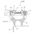
前記テーブル2の上面略中央部には、図2(a)に拡大して示すように、ワークWを上下逆さに向けて保持するための保治具4が配設されている。一方、同図(b)にも示すように保治具4の上方には、下方に向かって開口するコ字状の押さえ治具5が配置されており、エアシリンダ6によって上下動するようになっている。エアシリンダ6は、フレーム1の上部から前方に向かって延びる支持板7に倒立状態で配設されていて、その下端から突出するロッド5aが支持板7を貫通して下方に延びている。
A holding
また、エアシリンダ6の左右両側の部位においてそれぞれ支持板7を貫通して上下に伸びるようにガイドシリンダ8,8が配設されており、これら左右のガイドシリンダ8,8の内筒の下端には矩形の板部材9(以下、クロスヘッドという)が架設されている。このクロスヘッド9の上面略中央部にエアシリンダ6のロッド5aの下端が連結されており、該エアシリンダ6が作動すると、クロスヘッド9が左右のガイドシリンダ8,8に案内されて上下に平行移動することになる。
In addition,
そうして上下に移動するクロスヘッド9の下面に前記押さえ治具5が取り付けられており、これがクロスヘッド9と共に下降して、下方のテーブル2の保治具4にセットされているワークWを押さえ付ける。この保治具4には、図2(a)や図4にも示すように上向きの半球状突部4aが形成されていて、ワークWであるエンジンマウントのダイヤフラムD(図3にのみ示す)を内方(この例では上方)に押圧し、その液室w1の容積を所定量に設定するようになっている。
Thus, the holding
−マウントMの構造−
ここで、図3に一例を示すように、ワークWであるエンジンマウントMは、ボルト等によりエンジン側に連結されるブラケット部c1が一体に形成された扁平な円筒状の金属製ケースCと、このケースCの下方内周側に配設されて車体フレーム等に連結される連結金具Bと、これらケースC及び連結金具Bを互いに連結するゴム弾性体Rとを備えている。連結金具Bは概略L字状に形成され、その上部には半球状の膨出部b1が形成されている。
-Structure of mount M-
Here, as shown in FIG. 3, for example, the engine mount M that is the workpiece W includes a flat cylindrical metal case C integrally formed with a bracket portion c1 connected to the engine side by a bolt or the like, A connection fitting B disposed on the lower inner peripheral side of the case C and connected to a vehicle body frame and the like, and a rubber elastic body R for connecting the case C and the connection fitting B to each other are provided. The connection fitting B is formed in an approximately L shape, and a hemispherical bulging portion b1 is formed on the upper portion thereof.
前記ゴム弾性体Rは、ケースCの下部内周と連結金具Bの膨出部b1の外周とを互いに連結するように、下側に向かって窄んだ円錐状に形成されていて、上方に開口する中空部r1を有している。この中空部r1の上方の開口を閉塞するようにケースCの上部内周には、上方からオリフィス盤OとゴムダイヤフラムDとが嵌入されている。ダイヤフラムDの外周寄りの部位は厚肉に形成されて、オリフィス盤Oの外周全体を覆っており、そこには金属製の補強部材d1が埋め込まれている。 The rubber elastic body R is formed in a conical shape constricted downward so as to connect the lower inner periphery of the case C and the outer periphery of the bulging portion b1 of the connecting bracket B to each other. It has a hollow portion r1 that opens. An orifice panel O and a rubber diaphragm D are fitted into the upper inner periphery of the case C from above so as to close the opening above the hollow portion r1. A portion near the outer periphery of the diaphragm D is formed thick and covers the entire outer periphery of the orifice plate O, and a metal reinforcing member d1 is embedded therein.
そうしてダイヤフラムDにより開口を閉塞されて、ゴム弾性体Rの中空部r1は、後述の如く液体が封入される液室w1とされており(以下、液室w1という)、この液室w1がオリフィス盤Oによって下方の主液室と上方の副液室とに区画されている。これら主液室及び副液室は、オリフィス盤Oの外周寄りの部位に螺旋状に形成されたオリフィスo1によって互いに連通されており、その内部を流通する液体の抵抗によって振動を減衰させるようになっている。 Thus, the opening is closed by the diaphragm D, and the hollow portion r1 of the rubber elastic body R is a liquid chamber w1 in which a liquid is sealed as described later (hereinafter referred to as a liquid chamber w1). This liquid chamber w1 Is divided into a lower main liquid chamber and an upper sub liquid chamber by the orifice plate O. The main liquid chamber and the sub liquid chamber are communicated with each other by an orifice o1 formed in a spiral shape at a portion near the outer periphery of the orifice plate O, and the vibration is attenuated by the resistance of the liquid flowing through the inside. ing.
そうした液体の流動抵抗による減衰を適切に得るためには、エンジン等の静荷重を支持する状態(1G状態)でも液室w1内の圧力が過度に高くならないようにする必要があり、そのためには、図示の如くダイヤフラムDの中央部が内方に没入した状態でワークWに液体を封入しなくはならない。そこで、液体の封入時には、上述したようにワークWを保治具4に押し付けて、その半球状凸部4aによりダイヤフラムDを内方に押圧するようにしている。
In order to appropriately obtain such attenuation due to the flow resistance of the liquid, it is necessary to prevent the pressure in the liquid chamber w1 from becoming excessively high even in a state where the static load of the engine or the like is supported (1G state). As shown in the drawing, the liquid must be sealed in the workpiece W with the central portion of the diaphragm D immersed inward. Therefore, when the liquid is sealed, the workpiece W is pressed against the holding
また、図示の如くダイヤフラムDの外周寄りの部位には、その厚み方向(上下方向)に貫通し、下端がオリフィスo1を介して液室w1内に連通する封入孔d2(封入口)が形成されている。この封入孔d2の略中央部には球面状の拡径部が設けられており、詳しくは後述するが、そこに鋼球S(封止部材)が嵌め入れられることで、封入孔d2が閉止されるようになっている。 Further, as shown in the drawing, an enclosure hole d2 (enclosure opening) that penetrates in the thickness direction (vertical direction) and whose lower end communicates with the liquid chamber w1 through the orifice o1 is formed in a portion near the outer periphery of the diaphragm D. ing. A spherically enlarged diameter portion is provided at the substantially central portion of the sealing hole d2, and as will be described in detail later, a steel ball S (sealing member) is fitted therein, whereby the sealing hole d2 is closed. It has come to be.
−ノズル及びバルブユニット−
前記のようなワークWに液体を封入するときには、該ワークWを上下逆さ向きで保治具4にセットし、上述したように押さえ治具5によって上方から押さえ付ける。このとき、上下逆向きのワークWの下部に開口する封入孔d2には、図2(a)に示すように保治具4の上面に臨んで上向きに開口するノズル10が気密に接続され(図4に仮想線で示す)、このノズル10を介して排気や給液が行われるようになる。
-Nozzle and valve unit-
When the liquid is sealed in the workpiece W as described above, the workpiece W is set upside down on the holding
図4に示すように、前記ノズル10は、保治具4を上下に貫通しており、テーブル2上に配設された中間部材11を介して、該テーブル2の下方に配置されたバルブユニット12に接続されている。中間部材11は矩形ブロック状とされ、その内部には、上下方向に延びてノズル10内の通路とバルブユニット12のポートとを連通するように、給排通路11aが形成されている。尚、給排通路11aには、そこに鋼球Sを供給するための分岐路11bが接続されているが、これについては後述する。
As shown in FIG. 4, the
前記バルブユニット12は、矩形ブロック状のバルブボディ20を有し、図5のように上方から見た断面では4つの開閉バルブ21a,21b、22,23が十文字状に配置されている。そして、それらに囲まれた中央の共通通路24の上端が、バルブボディ20の上面に突設されたボス部20aの上面に開口して、共通の出口ポートとされている。各開閉バルブ21a,21b、22,23には、それぞれバルブボディ20の外部に突出するエアシリンダ71a,71b,72,73が一体的に連結されており、これによりスプールが移動されて開閉するようになっている。
The
図5において下側及び左側にそれぞれ位置する開閉バルブ21a,21bが、液室w1に液体を供給するための給液ライン31a,31bに接続され、上側に位置する開閉バルブ22が、ワークWの液室w1から空気を排出するための排気ライン50に接続され、右側に位置する開閉バルブ23が、ノズル10や中間部材11内に残留する液体を回収するための回収ライン60に接続されている。つまり、バルブユニット12は、ノズル10を給液ライン31a,31b、排気ライン50及び回収ライン60のいずれかに切替えて接続する切替バルブを構成している。
In FIG. 5, open /
−液体供給系統−
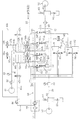
次に、図6を参照して、ワークWへの液体の供給系統について説明する。まず、給液ライン31a,31bには、液体を脱気しつつ貯留するための2つの貯留タンク32a,32bを備え、この各貯留タンク32a,32bの下部には、それぞれ給液ライン31a,31bを開閉する開閉バルブ33a,33bが配設されている。また、各貯留タンク32a,32bの下部にはドレンバルブ34a,34bも配設され、さらに、図外の液体補給装置から液体を補給するための上流側の給液ライン35が、電磁開閉バルブ36a,36bを介して接続されている。
-Liquid supply system-
Next, a liquid supply system to the workpiece W will be described with reference to FIG. First, the
一方、各貯留タンク32a,32bの上部には、大気に連通する大気連通ライン37a,37bと、低圧真空ポンプ41に連通する脱気ライン40と、後述するエア供給ライン80に連通する加圧ライン45とが接続されている。大気連通ライン37a,37bにはそれぞれ電磁開閉バルブ38a、38bが介設され、脱気ライン40及び加圧ライン45にも、それぞれ電磁開閉バルブ44a,44b、47a,47bが介設されている。
On the other hand, above the
すなわち、前記脱気ライン40には、上述したように比較的低圧の真空ポンプ41が接続されているとともに、この真空ポンプ41から貯留タンク32a,32bまでの間に、真空レギュレータ42と真空計43とが介設され、さらに貯留タンク32a,32bの直前で分岐したライン上にそれぞれ電磁開閉バルブ44a,44bが介設されている。この脱気ライン40は、真空ポンプ41によって貯留タンク32a,32b内の空気を吸引し、その内部に貯留した液体を脱気するためのものである。
That is, a relatively low-
また、前記加圧ライン45は、給液ライン31a,31bにより液体をバルブユニット12へ供給する際に、それを加圧するための加圧手段であり、上述したようにエア供給ライン80に連通されているとともに、その下流にはレギュレータ46が介設され、その下流で分岐した加圧ライン45a,45bにはそれぞれ電磁開閉バルブ47a,47bが介設されている。加圧ライン45は、本来、エアシリンダの作動のために供給されるエアの圧力をレギュレータ46により調整して、貯留タンク32a,32b内を加圧するようにしている。
The pressurizing
また、前記排気ライン50は、給液前にワークWの液室w1から空気を吸引(真空引き)するためのものであり、高圧真空ポンプ51に接続されていて、そこからバルブユニット12までの間に分離タンク52と真空圧力スイッチ53とが順に介設されている。分離タンク52は気液を分離するためのものであり、その上部には開放バルブ54が、その下部にはドレンバルブ55が、それぞれ取り付けられている。真空圧力スイッチ53は、真空引きする液室w1内の圧力をモニタするために用いられる。
The
さらに、回収ライン60は、給液後にノズル10や中間部材11内に残留する液体を吸引して回収するためのものであり、そうして液体を吸引するための真空ポンプ61に接続されるとともに、吸引される液体を回収して貯留する回収タンク62が介設されている。この回収タンク62は、前記分離タンク37と同様の構成であり、その上部には開放バルブ63が、その下部にはドレンバルブ64が、それぞれ取り付けられている。
Further, the
そして、前記2つの給液ライン31a,31b、排気ライン50、及び回収ライン60の4つのラインのいずれかが、バルブユニット12によって選択的にノズル10に接続される。すなわち、バルブユニット12の開閉バルブ21a,21bが開かれれば、給液ライン31a,31bがノズル10に接続され、開閉バルブ22が開かれれば排気ライン50が、また、開閉バルブ23が開かれれば回収ライン60が、ノズル10に接続される。
Any one of the four
前記4つの開閉バルブ21a,21b,22,23をそれぞれ駆動するエアシリンダ71a,71b,72,73は、電磁切替バルブ81a,81b,82,83を介してエア供給ライン80に接続されており、このエア供給ライン80は、フィルター・レギュレータ84を介して、図外のエア供給装置から高圧エアの供給を受けるようになっている。
また、前記エア供給ライン80は、電磁切替バルブ85を介して、押さえ治具5を上下動させるエアシリンダ6にも高圧エアを供給するようになっており、図6には示さないが、以下に述べる鋼球Sの供給機構90のエアシリンダ92,94,96(図4参照)にも図示省略の電磁切替バルブを介して高圧エアを供給し、さらに、その鋼球SをワークWの封入孔d2に嵌め入れる嵌入機構100のエアシリンダ102に対して、電磁切替バルブ86を介して高圧エアを供給するようになっている。
The
−鋼球の供給及び嵌入機構−
次に、再び前記図4を参照して、ノズル10に繋がる中間部材11の給排通路11aに鋼球Sを供給し、それをワークWの封入孔d2に嵌め入れる機構90,100について説明する。図示の如く、中間部材11には、上下に延びる給排通路11aの途中から分岐して、装置後方(同図の右方)に向かって直線的に延びるように分岐路11bが形成され、さらに、その分岐路11bの途中から分岐して上方に向かい中間部材11の上面に開口するように、分岐孔11cが形成されている。この分岐路11b及び分岐孔11cによって、給排通路11aに連通する一方、外部に開口する連通路が形成されている。
-Steel ball supply and insertion mechanism-
Next, referring to FIG. 4 again, the
前記分岐路11bは、中間部材11の後面まで延びてそこに開口しており、その開口には後方からロッド91が気密状態で挿入されている。このロッド91は、エアシリンダ92によって長手方向(装置の前後方向)に進退駆動されるようになっており、最も後退した位置では先端が分岐孔11cのやや後方に位置して、その分岐孔11cからの鋼球Sの供給を阻害しない一方、エアシリンダ92により駆動されて前進すれば、分岐路11bを通して鋼球Sを給排通路11aまで移動させることができる。
The branch path 11b extends to the rear surface of the
一方、前記中間部材11の上面に開口する分岐孔11cは、その上方に対峙する大径のロッド93の上下動によって開閉されるようになっている。このロッド93もエアシリンダ94によって長手方向(上下方向)に進退駆動されるようになっており、最も前進(下降)した位置では下端部に配設されたOリング(図示せず)が分岐孔11cの開口周縁に密着して、それを気密に封止する一方、そこから所定量、後退(上昇)すれば分岐孔11cの開口を開放し、鋼球Sの進入を妨げないようになる。
On the other hand, the
また、前記中間部材11の上面には、前後にスライド移動するようにスライド板95が配置されていて、その前部には鋼球Sを1つだけ収容可能な丸穴95aが厚み方向に貫通して形成されている一方、スライド板95の後端部はエアシリンダ96に連結されており、これにより前後方向に進退駆動されるようになっている。丸穴95aは、スライド板95が最も前進した位置にあるときに、下方の中間部材11上面に開口する分岐孔11cと連通する一方、スライド板95が最も後退すれば、以下に述べるように上方から供給される鋼球Sを受け入れる。
Further, a
すなわち、前記スライド板95の上には固定板13が重ねられて、スライド板95の左右両側で中間部材11に取り付けられており、この固定板13には、スライド板95の最後退位置でその丸穴95aに上方から連通するように、コネクタ14を介して可撓性チューブ15が取り付けられている。このチューブ15内には鋼球Sが数珠繋ぎになって収容されており、前記最後退位置にあるスライド板95の丸穴95aに、コネクタ14内の通路を介して鋼球Sを1つずつ供給するようになっている。
That is, the fixed
そうして供給された鋼球Sを1つ丸穴95a内に収容した状態で、エアシリンダ96の作動によりスライド板95がその最前進位置にまで移動されれば、丸穴95a内の鋼球Sは下方に開口する分岐孔11c内に落下して分岐路11bに至り、その後、前記したようにロッド91によって給排通路11aまで送られることになる。そして、給排通路11aに送られた鋼球Sは該給排通路11a内を落下して、バルブボディ20のボス部20aに開口するポートから共通通路24内に進入し、図示の如く共通通路24の内部に形成された段部に停留するようになる。
If the
斯くの如く鋼球Sを1つずつ給排通路11a内に供給する供給機構90は、分岐孔11cの開口を開閉する開閉機構としてロッド93及びエアシリンダ94を備えるとともに、その開閉作動に同期して鋼球Sを送り出し、給排通路11aまで1つずつ導入する送り機構として、ロッド91及びエアシリンダ92とスライド板95及びエアシリンダ96とを備えている。
As described above, the
そして、前記供給機構90により給排通路11a内に供給され、バルブボディ20の共通通路24内に停留する鋼球Sは、その後、今度はロッド101(押圧部材)によって押し上げられ、給排通路11aとノズル10内の通路とを通過して、ワークWの封入孔d2に嵌め入れられるようになっている。すなわち、前記バルブボディ20において共通通路24は、上端が中間部材11の給排通路11aに連通する一方、下端はバルブボディ20の下面に開口しており、この開口に下方からロッド101の上部が気密状態で挿入されている。
Then, the steel balls S supplied into the supply /
このロッド101は、その上端部が共通通路24から給排通路11aを経て、ノズル10内の通路に亘って進退するように設けられる一方、下端部がエアシリンダ102(駆動機構)に連結されて、このエアシリンダ102の作動より長手方向(上下方向)に進退駆動されるようになっており、最も後退(下降)した位置では、該ロッド101の先端が、4つの開閉バルブ21a,21b,22,23の相互の連通部位よりもやや下方(前記鋼球Sの停留部位よりも下方)に位置している。
The
そして、エアシリンダ102により駆動されてロッド101が前進(上昇)すれば、その上端が鋼球Sを押し上げて、給排通路11aからノズル10内の通路を通過させ、ワークWの封入孔d2に嵌め入れるようになる。つまり、前記ロッド101及びエアシリンダ102によって、鋼球Sをノズル10を介して封入孔d2に嵌め入れる嵌入機構100が構成されている。
When the
(液封マウントの製造手順)
次に、液封マウントの製造手順について説明する。まず、ワークW自体の製造について簡単に説明すると、この実施形態の液封マウントMの場合、連結金具B及びケースCを金型にセットするとともに、ゴム弾性体R及びゴム層となる所定量の未加硫ゴム組成物も金型にセットし、それらを加熱及び加圧して加硫一体化成形する。この際、連結金具B及びケースCにはゴムとの接触部位に加硫接着剤を塗布しておく。そうして得られた一体化形成物におけるケースCの上部内周にオリフィス盤OとゴムダイヤフラムDとを嵌め入れて、液体未封入のワークWを構成する。
(Manufacturing procedure for liquid ring mount)
Next, a manufacturing procedure of the liquid seal mount will be described. First, the manufacture of the workpiece W itself will be briefly described. In the case of the liquid seal mount M of this embodiment, the connecting metal fitting B and the case C are set in a mold, and a predetermined amount of the rubber elastic body R and the rubber layer are formed. The unvulcanized rubber composition is also set in a mold, and these are heated and pressurized to be integrally vulcanized. At this time, a vulcanizing adhesive is applied to the connection fitting B and the case C at the contact portion with the rubber. The orifice board O and the rubber diaphragm D are fitted into the upper inner periphery of the case C in the integrally formed product thus obtained to constitute a workpiece W without liquid filling.
前記のように構成したワークWに液体を封入する方法は、上述した液封入装置を用いて、液体を脱気する工程と、ワークWの液室w1内の空気を排気する工程と、排気後の液室w1に液体を供給する工程と、液体を満たした後に液室w1を密封する工程と、その後、ノズル10等に残留する液体を回収する工程と、を備えている。
The method of enclosing the liquid in the workpiece W configured as described above includes the step of degassing the liquid, the step of exhausting the air in the liquid chamber w1 of the workpiece W, and the A step of supplying the liquid to the liquid chamber w1, a step of sealing the liquid chamber w1 after the liquid is filled, and a step of recovering the liquid remaining in the
−脱気工程−
最初に液体を脱気する工程について説明する。この脱気工程は、貯留タンク32内の液体を脱気する工程であり、前記排気工程、給液工程、密封工程及び回収工程と並行して、2つの貯留タンク32a,32bで交互に行われるものである。以下の説明では、2つの貯留タンク32a,32bを区別することなく、単に貯留タンク32と呼ぶ。また、貯留タンク32には、既に液体が貯留されているものとする。
-Deaeration process-
First, the process of degassing the liquid will be described. This deaeration process is a process for degassing the liquid in the storage tank 32, and is performed alternately in the two
貯留タンク32内の液体を脱気するときには、脱気ライン40上に介設された電磁開閉バルブ44を開くとともに、真空ポンプ41を作動させて、真空計43により貯留タンク32内の圧力をモニタしながら、この貯留タンク32内の圧力を下げてゆく。この際、貯留タンク32に設けられた他のバルブは全て閉じておく。
When the liquid in the storage tank 32 is deaerated, the electromagnetic opening / closing valve 44 provided on the
そうして貯留タンク32内が所定の真空圧力に到達すれば、この貯留タンク32内で液体の脱気を所定時間、行い、それに溶け込んでいる空気を除去することで、マウントMに封入した後に液中で気泡が生成することを防止でき、防振性能を安定的に確保する上で有利になる。 If the inside of the storage tank 32 reaches a predetermined vacuum pressure, the liquid is degassed in the storage tank 32 for a predetermined time, and the air dissolved therein is removed, and after being sealed in the mount M It is possible to prevent the generation of bubbles in the liquid, which is advantageous in ensuring stable vibration isolation performance.
これに対し、排気行程、給液工程、密封工程及び回収工程は、この順番の一連のシーケンスとして行われる。まず、作業者は、図1、2(a)のように押さえ治具5が上方に離れている状態で、ワークWを上下逆さ向きにしてテーブル2上の保治具4にセットする。この際、作業者は、保治具4上に上向きに開口するノズル10を目安にして、これに封入孔d2が合うようにワークWを載置すればよい。それから装置フレーム1の最上部に配設されている操作盤16(図1参照)のスイッチを押して、液封入装置を作動させる。
On the other hand, the exhaust process, the liquid supply process, the sealing process, and the recovery process are performed as a series of sequences in this order. First, the operator sets the work W upside down and on the holding
−排気工程−
液封入装置が作動すると、まず、エアシリンダ6の作動によって押さえ治具5が下降し、逆さ向きのワークWの上部に位置する連結金具Bに当接して、上方から押圧する。そうすると、逆さ向きのワークWの下部に開口する封入孔d2が、図4の如くノズル10と気密に接続される。また、供給機構90のスライド板95が前進して、中間部材11の分岐孔11cに鋼球Sが1つだけ落下した後に、ロッド93が下降して分岐孔11cの開口を気密に封止する。
-Exhaust process-
When the liquid sealing apparatus is operated, first, the holding
こうして、ワークWの液室w1にノズル10を介して連通する中間部材11の給排通路11a及びバルブユニット12内の共通通路24が外部から気密に遮断された状態で、該バルブユニット12における排気ライン50の開閉バルブ22のみが開かれる。尚、排気ライン50の高圧真空ポンプ51は常時、作動させておく。
Thus, in the state where the supply /
その開閉バルブ22の開作動によって、真空圧力スイッチ53をモニタしながらワークWの液室w1内の空気が吸引(真空引き)されて、強制的に排気される。この際、ノズル10や中間部材11、さらにはバルブユニット12内からも空気が排出される。そして、例えば液室w1内が所定の高真空圧状態になれば、バルブユニット12では排気ライン50の開閉バルブ22が閉じられる。
By opening the opening / closing
−給液工程−
前記のようにワークWの液室w1から空気が排出されれば、今度はバルブユニット12において、既に脱気の完了している貯留タンク32に接続された給液ライン31の開閉バルブ21が開かれる(貯留タンク32に倣って、給液ライン31a,31bや開閉バルブ21a,21b等も区別せずに説明する)。それに先立って、貯留タンク32では、まず、脱気ライン40の開閉バルブ44を閉じるとともに、大気連通ライン37上の開閉バルブ38を開いて一旦、大気開放した後に、それを閉じて加圧ライン45上の開閉バルブ47を開き、タンク内を加圧する。
-Liquid supply process-
If air is discharged from the liquid chamber w1 of the workpiece W as described above, the
そうして加圧された状態で貯留タンク32内の液体は、給液ライン31を流通してバルブユニット12へ供給され、ノズル10を介してワークWの液室w1内に供給される。この際、上下逆向きのワークWの液室w1にその下方から上向きに液体を供給することになるが、前記のように貯留タンク32内が加圧されている一方、液室w1内は負圧になっているので、液体はスムーズに供給されて液室w1の隅々にまで充填される。
In this state, the liquid in the storage tank 32 is supplied to the
−密封工程−
そうして液室w1内に液体が満たされれば、バルブユニット12では給液ライン31の開閉バルブ21が閉じられる。また、中間部材11の分岐路11bでは、そこに挿入されている供給機構90のロッド91が前進して、鋼球Sを給排通路11aに送り、続いて嵌入機構100のロッド101が上昇して、鋼球Sを給排通路11a及びノズル10内の通路を介して、ワークWの封入孔d2に嵌め入れて閉止する。
-Sealing process-
When the liquid chamber w1 is filled with the liquid, the
そうして鋼球Sの送られる分岐路11bや給排通路11a内は液体が満たされているので、そこを通って鋼球Sが封入孔d2に嵌入されるときに、空気が混入する虞れはない。また、鋼球Sの嵌入に伴い封入孔d2から押し出された液体はノズル10及び中間部材11内に留まり、外部にこぼれる心配はない。勿論、空気中の異物が封入液に混入する虞れもない。
Thus, since the inside of the branch passage 11b and the supply /
−回収工程−
前記のようにして封入孔d2が閉止され、液室w1が密封されて、液封マウントMが完成すれば、バルブユニット12では回収ライン60の開閉バルブ23のみが開かれる。そうすると、該回収ライン60の真空ポンプ61は常時、作動しているので、回収タンク62内が負圧とされ、この負圧によってバルブユニット12や中間部材11、さらにはノズル10内に残留している液体が吸引されて、回収タンク62に回収される。
-Recovery process-
When the sealing hole d2 is closed as described above, the liquid chamber w1 is sealed, and the liquid sealing mount M is completed, only the opening / closing
そして、予め設定されている時間が経過すれば、バルブユニット12では回収ライン60の開閉バルブ23が閉じられる。また、エアシリンダ6の作動によって押さえ治具5が上昇し、作業者は、完成したマウントMをテーブル2上の保治具4から取り外すことができるようになる。
When a preset time has elapsed, the
そうしてマウントMを取り外しても、前記したようにノズル10内からは既に液体が回収されており、このノズル10が接続されていた封入孔d2の付近からも液体は除去されているので、こぼれた液体がマウントMに付着する心配はなく、それを拭き取る手間も要らない。作業者は、完成したマウントMを取り外した後に、次のワークWを保治具4にセットして操作盤16のスイッチを押し、前記した排気、給液、密封及び回収の各工程を、液封入装置にて実行すればよい。
Even if the mount M is removed, the liquid has already been recovered from the inside of the
(作用効果)
したがって、この実施形態の液封入装置によると、保治具4にセットしたワークWの封入孔d2に気密にノズル10を接続した状態で、これを介して液室w1内の空気を排出し、続いて液体を充填した後に、そのノズル10を介して鋼球Sを封入孔d2に嵌め入れるようにしたから、液体の封入から鋼球Sによって封止するまでの間に液室w1に空気や異物の混入する虞れがなく、また、液体が外部にこぼれる心配もない。
(Function and effect)
Therefore, according to the liquid sealing apparatus of this embodiment, the air in the liquid chamber w1 is exhausted through the
特にこの実施形態では、ワークWからノズル10を取り外す前に、そのノズル10や中間部材11に残留する液体を吸引して、回収するようにしたから、その後、完成したマウントMを取り外しても、こぼれた液体がマウントMに付着することはない。しかも、そうして回収して再利用する液体に空気や異物が混入することもない。
In particular, in this embodiment, before removing the
さらに、前記のように液封入装置にワークWをセットして、操作盤16のスイッチを押すだけで、ワークWの液室w1が排気され、そこへ液体が充填されて密封されるとともに、残液の回収までもが一連のシーケンスとして自動的に行われる上に、この実施形態ではワークWを上下逆さ向きにしているので、その封入孔d2をノズル10に合わせてセットすることも容易であり、作業性は非常に高いと言える。
Furthermore, just by setting the workpiece W in the liquid sealing device as described above and pressing the switch on the
そして、マウントM(ワークW)の封入孔d2を従来例(特許文献2)のもののように複雑な構造としなくても済み、マウントMの設計や製造において無用の制約を生じることもないし、その封入孔d2に予めピン等の封止部材を挿入しておく必要もなく、封入孔d2や封止部材である鋼球Sの寸法精度を特に高くする必要もないから、コストの増大を防止することができる。 And it is not necessary to make the enclosure hole d2 of the mount M (work W) have a complicated structure as in the conventional example (Patent Document 2), and there is no unnecessary restriction in the design and manufacture of the mount M. It is not necessary to insert a sealing member such as a pin into the sealing hole d2 in advance, and it is not necessary to increase the dimensional accuracy of the steel ball S that is the sealing hole d2 or the sealing member, thereby preventing an increase in cost. be able to.
つまり、液封マウントMのコスト増大を招くことなく、製造時の作業性を高めることができるとともに、液体の封入後に空気や異物が混入することを阻止して、防振性能を安定的に確保することができ、さらに、封入液のこぼれを阻止して、金具部分の錆の発生を未然に防止することができるのである。 In other words, the workability during manufacturing can be improved without incurring an increase in the cost of the liquid seal mount M, and air and foreign matter can be prevented from being mixed in after the liquid has been sealed, thereby ensuring stable vibration isolation performance. Furthermore, it is possible to prevent spillage of the encapsulated liquid and prevent rust from occurring on the metal part.
(他の実施形態)
尚、本発明は、前記実施形態の構成に限定されるものではなく、その他の種々の構成をも包含する。すなわち、前記実施形態の液封入装置には回収ライン60が設けられているが、これは必ずしも必要ではない。前記実施形態のようにノズル10を上向きに設けた場合、ワークWへの液体の供給が終了すれば、ノズル10内の液体を重力により流下させて、中間部材11やバルブユニット12内に戻すことができ、そこからドレインさせたり、或いは給液ライン31に戻したりすることも可能である。
(Other embodiments)
In addition, this invention is not limited to the structure of the said embodiment, It includes other various structures. That is, although the
また、前記実施形態ではバルブユニット12を、4つの開閉バルブ21a,21b,22,23を備えるものとしているが、これは1〜3個のバルブにて構成することも可能である。
Moreover, in the said embodiment, although the
また、前記実施形態では液封入装置に貯留タンク32を2つ設けているが、これは1つであってもよい。さらに貯留タンク32内を脱気することも必須ではないし、液体の供給時に加圧することも必ずしも必要ではない。 Further, in the above embodiment, two storage tanks 32 are provided in the liquid sealing apparatus, but this may be one. Further, it is not essential to deaerate the inside of the storage tank 32, and it is not always necessary to pressurize when supplying the liquid.
前記実施形態では、一例として縦型の液封マウントMを示したが、特にこれに限定されるものではなく、本発明の封入装置及び方法は、その他の液封マウントにも適用可能である。 In the above-described embodiment, the vertical liquid ring mount M is shown as an example. However, the present invention is not particularly limited thereto, and the sealing device and method of the present invention can be applied to other liquid ring mounts.
以上、説明したように、本発明は、液封マウントのコスト増大を招くことなく、製造時の作業性を高めることができるとともに、その性能を安定的に確保することができるので、有用である。 As described above, the present invention is useful because it can improve the workability at the time of manufacture without incurring the cost increase of the liquid seal mount, and can stably ensure the performance. .
M 液封マウント
S 鋼球(封止部材)
W ワーク(マウントワーク)
w1 液室
d2 封入孔(封入口)
2 テーブル(載置台)
4 保治具
10 ノズル
11 中間部材
11a 給排通路
11b 分岐路(連通路)
11c 分岐孔(連通路)
12 バルブユニット(切替バルブ)
31 給液ライン
32 貯留タンク(加圧手段)
45 加圧ライン(加圧手段)
50 排気ライン
60 回収ライン
90 供給機構(供給手段)
91 ロッド(送り機構)
92 エアシリンダ(送り機構)
93 ロッド(開閉機構)
94 エアシリンダ(開閉機構)
95 スライド板(送り機構)
96 エアシリンダ(送り機構)
100 嵌入機構(嵌入手段)
101 ロッド(押圧部材)
102 エアシリンダ(駆動機構)
M Liquid seal mount S Steel ball (sealing member)
W Work (Mount Work)
w1 Liquid chamber d2 Enclosure hole (enclosure port)
2 Table (mounting table)
4 Holding
11c Branch hole (communication path)
12 Valve unit (switching valve)
31 Liquid supply line 32 Storage tank (pressurizing means)
45 Pressurizing line (pressurizing means)
50
91 Rod (feed mechanism)
92 Air cylinder (feed mechanism)
93 Rod (Opening / closing mechanism)
94 Air cylinder (opening / closing mechanism)
95 Slide plate (feed mechanism)
96 Air cylinder (feed mechanism)
100 Insertion mechanism (insertion means)
101 Rod (Pressing member)
102 Air cylinder (drive mechanism)
Claims (5)
前記マウントワークを載置する台上に上向きに配設され、前記マウントワークの液室に連通する封入口に気密に接続されるノズルと、
前記ノズルを、前記マウントワークの液室から空気を排出するための排気ラインと、該排気後の液室に液体を供給するための給液ラインとに切替えて接続する切替バルブと、
前記ノズル及び切替バルブの中間に設けられ、前記液室に対する排気及び給液のための給排通路を有する中間部材と、
前記中間部材の給排通路内に、前記マウントワークの封入口を封止するための封止部材を供給する供給手段と、
前記供給手段により給排通路内に供給された封止部材を、前記ノズルを介して封入口に嵌め入れる嵌入手段と、を備え、
前記給液ラインには、供給する液体を加圧する加圧手段が配設されている
ことを特徴とする液封マウント用の液封入装置。 A liquid sealing device for liquid seal mounting that seals liquid in a liquid chamber of a mount work,
A nozzle that is disposed upward on a table on which the mount work is placed, and is hermetically connected to a sealing port that communicates with a liquid chamber of the mount work;
A switching valve for switching and connecting the nozzle to an exhaust line for discharging air from the liquid chamber of the mount work and a liquid supply line for supplying liquid to the liquid chamber after the exhaust;
An intermediate member provided between the nozzle and the switching valve and having a supply / discharge passage for exhausting and supplying liquid to the liquid chamber;
Supply means for supplying a sealing member for sealing the sealing port of the mount work into the supply / discharge passage of the intermediate member;
Fitting means for fitting the sealing member supplied into the supply / discharge passage by the supply means into the sealing port via the nozzle ;
A liquid sealing device for a liquid seal mount, wherein the liquid supply line is provided with pressurizing means for pressurizing a liquid to be supplied .
供給手段は、前記連通路の開口を開閉する開閉機構と、その開閉作動に同期して封止部材を1つずつ送り出し、前記連通路を介して給排通路に導入する送り機構と、を備えていることを特徴とする請求項1に記載の液封入装置。 The intermediate member is provided with a communication path that opens to the outside while communicating with the supply / discharge path.
The supply means includes an opening / closing mechanism that opens and closes the opening of the communication path, and a feeding mechanism that sends the sealing member one by one in synchronization with the opening / closing operation and introduces the sealing member into the supply / discharge path via the communication path. The liquid sealing apparatus according to claim 1, wherein:
切替バルブは、前記ノズル及び中間部材を、排気ライン、給液ライン又は前記回収ラインのいずれか1つに切替えて接続するように構成されている
ことを特徴とする請求項1〜3のいずれか1つに記載の液封入装置。 A collection line for sucking and collecting the liquid remaining in the nozzle and the intermediate member is provided,
Switching valve, the nozzle and the intermediate member, the exhaust line, claim 1-3, characterized in that it is configured to connect to switch to one of the supply fluid line or the return line The liquid sealing apparatus according to one.
マウントワークを載置する台上にマウントワークを、前記マウントワークの液室に連通する下向きにした封入口が前記台上に上向きに配設したノズルに合わさるようにして載置し、
前記封入口にノズルを気密に接続し、
そのノズルを介して前記液室内の空気を排出した後に、そこに液体を加圧して供給し、さらに、当該ノズルを介して前記封入口に封止部材を嵌め入れる
ことを特徴とする液封マウントの製造方法。 A method for producing a liquid seal mount by enclosing a liquid in a liquid chamber of a mount work,
The mount work is placed on a table on which the mount work is placed so that the downwardly sealed inlet communicating with the liquid chamber of the mount work is aligned with the nozzle disposed upward on the table,
Before connecting the nozzle hermetically Kifu inlet,
A liquid seal mount characterized in that after the air in the liquid chamber is discharged through the nozzle, the liquid is pressurized and supplied thereto, and a sealing member is fitted into the sealing port through the nozzle. Manufacturing method.
Priority Applications (1)
| Application Number | Priority Date | Filing Date | Title |
|---|---|---|---|
| JP2006184356A JP4767112B2 (en) | 2006-07-04 | 2006-07-04 | Liquid sealing device for liquid ring mount and method for manufacturing liquid ring mount |
Applications Claiming Priority (1)
| Application Number | Priority Date | Filing Date | Title |
|---|---|---|---|
| JP2006184356A JP4767112B2 (en) | 2006-07-04 | 2006-07-04 | Liquid sealing device for liquid ring mount and method for manufacturing liquid ring mount |
Publications (2)
| Publication Number | Publication Date |
|---|---|
| JP2008014367A JP2008014367A (en) | 2008-01-24 |
| JP4767112B2 true JP4767112B2 (en) | 2011-09-07 |
Family
ID=39071589
Family Applications (1)
| Application Number | Title | Priority Date | Filing Date |
|---|---|---|---|
| JP2006184356A Active JP4767112B2 (en) | 2006-07-04 | 2006-07-04 | Liquid sealing device for liquid ring mount and method for manufacturing liquid ring mount |
Country Status (1)
| Country | Link |
|---|---|
| JP (1) | JP4767112B2 (en) |
Cited By (1)
| Publication number | Priority date | Publication date | Assignee | Title |
|---|---|---|---|---|
| CN111322346A (en) * | 2018-12-14 | 2020-06-23 | 通伊欧轮胎株式会社 | Mounting table and method for orifice member, and method for manufacturing liquid-sealed vibration-proof mount |
Families Citing this family (1)
| Publication number | Priority date | Publication date | Assignee | Title |
|---|---|---|---|---|
| EP2343464B1 (en) * | 2008-10-28 | 2016-06-22 | Bridgestone Corporation | Method for manufacturing anti-vibration device |
Family Cites Families (4)
| Publication number | Priority date | Publication date | Assignee | Title |
|---|---|---|---|---|
| JPH0826903B2 (en) * | 1990-08-01 | 1996-03-21 | 本田技研工業株式会社 | Viscous joint oil injection device and injection method |
| JP2002005585A (en) * | 2000-04-19 | 2002-01-09 | Minoura:Kk | Heat pipe |
| JP2002113620A (en) * | 2000-10-10 | 2002-04-16 | Nok Corp | Steel ball press-fitting device |
| JP4221237B2 (en) * | 2003-03-19 | 2009-02-12 | 倉敷化工株式会社 | Encapsulation device for encapsulating liquid for liquid encapsulated mount, and method for manufacturing liquid encapsulated mount |
-
2006
- 2006-07-04 JP JP2006184356A patent/JP4767112B2/en active Active
Cited By (2)
| Publication number | Priority date | Publication date | Assignee | Title |
|---|---|---|---|---|
| CN111322346A (en) * | 2018-12-14 | 2020-06-23 | 通伊欧轮胎株式会社 | Mounting table and method for orifice member, and method for manufacturing liquid-sealed vibration-proof mount |
| CN111322346B (en) * | 2018-12-14 | 2021-05-14 | 通伊欧轮胎株式会社 | Mounting table and method for orifice member, and method for manufacturing liquid-sealed vibration-proof mount |
Also Published As
| Publication number | Publication date |
|---|---|
| JP2008014367A (en) | 2008-01-24 |
Similar Documents
| Publication | Publication Date | Title |
|---|---|---|
| CN100581923C (en) | Method and apparatus for filling liquids into foil bags with a spout | |
| US8757449B2 (en) | Air bubble ingress prevention mechanism, liquid material discharge device provided with the same, and liquid material discharge method | |
| JPH1135003A (en) | Filling nozzle, and liquid filling method | |
| JP4767112B2 (en) | Liquid sealing device for liquid ring mount and method for manufacturing liquid ring mount | |
| JP4221237B2 (en) | Encapsulation device for encapsulating liquid for liquid encapsulated mount, and method for manufacturing liquid encapsulated mount | |
| JP4978842B2 (en) | Liquid sealing device for liquid ring mount, and method for manufacturing liquid ring mount using the same | |
| KR100493781B1 (en) | A fluid injector and method of manufacturing a battery cell | |
| JP3969712B2 (en) | Degassing method and degassing device for bagging and packaging machine | |
| JP4767117B2 (en) | Liquid sealing device for liquid ring mount | |
| JP4487913B2 (en) | Oil vacuum filling device | |
| JP4833759B2 (en) | Liquid sealing device for liquid ring mount | |
| JP4424480B2 (en) | COATING UNIT, COATING APPARATUS PROVIDED WITH THE COATING UNIT, AND METHOD OF PACKING THE COATING UNIT | |
| JP2722137B2 (en) | Method and apparatus for vacuum impregnation of electrolytic capacitor element with electrolytic solution | |
| US7937979B2 (en) | Gravity fill system with pressure check valve | |
| CN219976162U (en) | Vacuum priming device | |
| JP3869890B2 (en) | Manufacturing method of liquid-sealed anti-vibration mount | |
| JP3943803B2 (en) | Liquid injection device | |
| JP4626156B2 (en) | Liquid injection device and injection method, cartridge, and droplet discharge device | |
| JP3654106B2 (en) | Liquid injection method and liquid injection device | |
| JP3555399B2 (en) | Oil filling device and oil filling method | |
| KR100763855B1 (en) | An air bubble remover system of liquid crystal | |
| JP2000281188A (en) | Liquid filling nozzle and liquid filling method | |
| JPH0516794A (en) | Method and device for pouring hydraulic oil to motor bicycle and tricycle and oil gun therefor | |
| JPH08166028A (en) | Structure of oil pressure circuit | |
| CN117000548A (en) | Liquid introduction method, liquid introduction mechanism, and liquid introduction apparatus |
Legal Events
| Date | Code | Title | Description |
|---|---|---|---|
| A621 | Written request for application examination |
Free format text: JAPANESE INTERMEDIATE CODE: A621 Effective date: 20090520 |
|
| A977 | Report on retrieval |
Free format text: JAPANESE INTERMEDIATE CODE: A971007 Effective date: 20110113 |
|
| A131 | Notification of reasons for refusal |
Free format text: JAPANESE INTERMEDIATE CODE: A131 Effective date: 20110201 |
|
| A521 | Request for written amendment filed |
Free format text: JAPANESE INTERMEDIATE CODE: A523 Effective date: 20110311 |
|
| TRDD | Decision of grant or rejection written | ||
| A01 | Written decision to grant a patent or to grant a registration (utility model) |
Free format text: JAPANESE INTERMEDIATE CODE: A01 Effective date: 20110531 |
|
| A01 | Written decision to grant a patent or to grant a registration (utility model) |
Free format text: JAPANESE INTERMEDIATE CODE: A01 |
|
| A61 | First payment of annual fees (during grant procedure) |
Free format text: JAPANESE INTERMEDIATE CODE: A61 Effective date: 20110614 |
|
| R150 | Certificate of patent or registration of utility model |
Ref document number: 4767112 Country of ref document: JP Free format text: JAPANESE INTERMEDIATE CODE: R150 Free format text: JAPANESE INTERMEDIATE CODE: R150 |
|
| FPAY | Renewal fee payment (event date is renewal date of database) |
Free format text: PAYMENT UNTIL: 20140624 Year of fee payment: 3 |
|
| R250 | Receipt of annual fees |
Free format text: JAPANESE INTERMEDIATE CODE: R250 |
|
| R250 | Receipt of annual fees |
Free format text: JAPANESE INTERMEDIATE CODE: R250 |
|
| R250 | Receipt of annual fees |
Free format text: JAPANESE INTERMEDIATE CODE: R250 |
|
| R250 | Receipt of annual fees |
Free format text: JAPANESE INTERMEDIATE CODE: R250 |
|
| R250 | Receipt of annual fees |
Free format text: JAPANESE INTERMEDIATE CODE: R250 |
|
| R250 | Receipt of annual fees |
Free format text: JAPANESE INTERMEDIATE CODE: R250 |
|
| R250 | Receipt of annual fees |
Free format text: JAPANESE INTERMEDIATE CODE: R250 |
|
| R250 | Receipt of annual fees |
Free format text: JAPANESE INTERMEDIATE CODE: R250 |
|
| R250 | Receipt of annual fees |
Free format text: JAPANESE INTERMEDIATE CODE: R250 |
|
| R250 | Receipt of annual fees |
Free format text: JAPANESE INTERMEDIATE CODE: R250 |