JP4765166B2 - Coating liquid application equipment - Google Patents
Coating liquid application equipment Download PDFInfo
- Publication number
- JP4765166B2 JP4765166B2 JP2000383508A JP2000383508A JP4765166B2 JP 4765166 B2 JP4765166 B2 JP 4765166B2 JP 2000383508 A JP2000383508 A JP 2000383508A JP 2000383508 A JP2000383508 A JP 2000383508A JP 4765166 B2 JP4765166 B2 JP 4765166B2
- Authority
- JP
- Japan
- Prior art keywords
- substrate
- detection
- coating
- coating liquid
- lifting
- Prior art date
- Legal status (The legal status is an assumption and is not a legal conclusion. Google has not performed a legal analysis and makes no representation as to the accuracy of the status listed.)
- Expired - Fee Related
Links
Images


Description
【0001】
【発明の属する技術分野】
本発明は、たとえば基板の表面上にストライプ状に形成された凹部に塗液を塗布する塗液の塗布装置および方法に関し、とくにプラズマディスプレイ用発光基板の製造装置および方法に関する。
【0002】
【従来の技術】
従来から、テーブル上に載置され塗液が塗布される基板として、たとえばプラズマディスプレイ用発光基板やLCD用発光基板等がある。プラズマディスプレイ用発光基板には、基板の表面に塗布方向に延びる複数の縦リブが形成されたものや、近年、輝度やコントラスト向上、低消費電力化の要請に応えるべく、基板表面に格子状の凹部が形成された基板も採用されている(たとえば、特開平11−213896号公報、特開2000−123747号公報)。また、テーブル上に載置された基板に塗液を塗布する装置としては、特開平11−274274号公報記載のようなものが知られている。また、塗布装置等における基板の位置を確認するためのアライメントマーク検出手段としては、特開平5−294405号公報の基板検出装置の基板検出方法と同様に一般的には、基板の上面側、つまり、塗液の塗布面よりテーブル側へ向けてマーク検出手段を配置している。
【0003】
【発明が解決しようとする課題】
しかしながら、特開平11−274274号公報のような装置においては、基板昇降手段のピン上の基板の検知は可能であるが、テーブル上の基板の検知は行えず、なおかつ基板検知手段が投受光式のものであるため、基板の上方に受光部または投光部を設ける必要がある。とくに、基板の上方には、塗布ヘッドやそれらを動作させるための機構が備わっているため、基板の上方側への基板検知手段の配設は、装置を大型化するおそれがある。また、誤作動時等においては、塗布ヘッドとの干渉も懸念され装置の破損を招来するおそれがある。
【0004】
また、基板サイズの種類についても、作業者が現在投入中の基板サイズの種類を把握しているのみであり、もし、何かのミスで他の種類のサイズの基板が投入された場合、たとえば、小さいサイズの基板に塗液を塗布するのに誤って大きいサイズの基板が投入された場合、塗液が塗布されない領域がでてくる。
【0005】
一方、アライメントマーク検出手段についても同様に、塗布ヘッドとの干渉も懸念されるし、一連の動作上、基板をテーブルに載置し、吸着手段により基板を吸着後、マーク検出手段が基板に付設されたマークを検出しに行く動作となる。したがって、マーク検出手段が基板に付設されたマークを検出しに行く時間が、本装置のタクトタイムのロスとなり、生産性の向上が望めない。
【0006】
本発明の課題は、装置の大型化を防止しつつ、テーブル上または基板昇降手段上の基板の有無を確実に検知するとともに、基板表面のアライメントマークを検出し、装置の誤作動を防止でき、さらに生産性を向上することのできる塗液の塗布装置および方法並びにプラズマディスプレイ用部材の製造装置および方法を提供することにある。
【0007】
【課題を解決するための手段】
上記課題を解決するために、本発明の塗液の塗布装置は、塗液が塗布される基板を吸着固定するテーブルと、前記基板と対向する位置において基板に塗液を塗布する塗布ヘッドと、前記テーブルと塗布ヘッドを相対移動する移動手段と、前記基板をテーブル上に載置するとともにテーブル上から離間させる基板昇降手段とを有する塗液の塗布装置において、前記テーブルに厚み方向に貫通する検出孔を形成するとともに、該検出孔に、テーブル上または基板昇降手段上の基板の有無を検知する基板検知手段の検出ヘッド部を内挿し、前記基板検知手段の検出ヘッド部を基板昇降手段に支持させ、該検出ヘッド部を基板昇降手段とともに昇降可能に構成したことを特徴とするものからなる。
【0010】
上記の如く、上記基板検知手段の検出ヘッド部は基板昇降手段に支持されている。つまり、基板昇降手段が降下した状態においては検出ヘッド部がテーブルの検出孔に内設されるように、また基板昇降手段が上昇した場合には、検出孔からテーブルの基板載置面よりも突出するように構成することが可能である。この場合、基板と検出ヘッド部との間隔を常に一定に保つことができるので、基板の有無検知の信頼度を向上することができる。
【0012】
上記基板検知手段の検出ヘッド部は、たとえばCCDカメラ、光ファイバ光電センサ等を用いることができる。また、基板は、一般的に透明(無色透明、着色透明、無色半透明、着色半透明を含む。)なガラスが用いられる。したがって、検出ヘッド部としてCCDカメラを用いれば、基板の反塗布面側からでもアライメントマークを検出することもできるので、基板検知手段にアライメントマーク検出機能を付与することができる。一方、アライメントマーク検出手段の検出ヘッド部にCCDカメラを用いれば、アライメントマークの検出と併せて基板の有無も検知することができるので、アライメントマーク検出手段に基板検知機能を付与することもできる。上記のように基板検知手段にアライメントマーク検出機能を付与するか、あるいはアライメントマーク検出手段に基板検知機能を付与すれば、基板検知とアライメントマークの検出を同時に行うことができるので、装置のタクトタイムのロスを大幅に低減し生産性を向上することができる。
【0013】
上記課題を解決するために、本発明の塗液の塗布方法は、前記基板をテーブル上に移動するステップと、前記基板を基板昇降手段により支持し、前記テーブル上に載置するステップと、前記基板を基板検知手段の検出ヘッド部により検知するステップと、前記基板と対向する位置に配した塗布ヘッドにて、塗液を前記基板上に塗布するステップとを有し、前記検出ヘッド部は、前記基板に対して前記テーブル側に配され、前記基板昇降手段の昇降とともに、昇降することを特徴とする。
また、前記基板昇降手段の上昇時に、該手段と前記塗布ヘッドとが干渉し合う位置関係にある場合には、基板昇降手段の上昇を停止するようにしてもよい。
【0016】
また、上記のような塗液の塗布方法においては、テーブル上又は基板昇降手段上の基板の有無が検知され、基板が存在する場合には、基板供給手段による新たな基板の供給が停止されるので、装置の誤作動を防止し、不良基板の発生を確実に防止することができる。
【0017】
【発明の実施の形態】
以下に、本発明の望ましい実施の形態について図面を参照して説明する。
図1は、本発明の第1実施態様に係る塗液の塗布装置の斜視図である。この塗布装置は、被塗布基板1(本実施態様においては、プラズマディスプレイ用発光基板)の表面に所定の方向に複数列のストライプ状の塗液の塗着部を形成する装置である。図1において、塗布装置は、機台2上にX軸方向に延びるXスライドレール3a、3bを有している。Xスライドレール3a、3b上にはX軸方向にスライド走行可能にXスライドテーブル4が設けられている。Xスライドテーブル4には、該テーブル4をX軸方向にスライドさせるための駆動軸5が係合されている。Xスライドテーブル4はX軸モータ6によりX軸方向にスライドされるようになっている。基板1は、Xスライドテーブル4上に位置決めされ着脱自在に吸着支持される。
【0018】
機台2の上方には、該機台2を跨ぐように門型の支持機台7が設けられている。支持機台7は手前側の側面7aに、Y軸方向に延びるYスライドレール8a、8bを有している。Yスライドレール8a、8b上にはY軸方向にスライド走行可能にYスライドテーブル9が設けられている。Yスライドテーブル9には、該テーブル9をY軸方向にスライドさせるための駆動軸10が係合されている。Yスライドテーブル9はY軸モータ11によりY軸方向にスライドされるようになっている。Xスライドテーブル4、Yスライドテーブル9等により塗布ヘッド18と被塗布基板1とを塗布方向(X軸、Y軸方向)に相対移動させる第1の移動手段29aが構成されている。
【0019】
Yスライドテーブル9上には、Z軸方向に延びるZスライドレール12a、12bが設けられている。Zスライドレール12a、12b上にはZ軸方向にスライド走行可能にZスライドテーブル13が設けられている。Zスライドテーブル13には該テーブル13をZ軸方向にスライドさせるための駆動軸14が係合されている。Zスライドテーブル13は、Z軸方向位置制御手段41に連結されるZ軸モータ15によりZ軸方向、すなわち塗布ヘッド18を基板1に接近、離間させる方向にスライドされるようになっている。このようにして、第2の移動手段29bが構成されている。
【0020】
Zスライドテーブル13には、塗布ヘッド18が取り付けられている。Yスライドテーブル9には、塗布ヘッド18のY軸方向の位置を検出するための位置センサ17が取り付けられている。位置センサ17は、支持機台7の上面においてY軸方向に設けられたセンサ支持軸16に移動自在に支持されている。Y軸モータ11には、Yスライドテーブル9の移動速度を変更するためのY軸方向速度制御手段20が連結されている。
【0021】
塗布ヘッド18は図1のY軸方向に移動され、塗布ヘッド18の下面板32に所定の間隔にて設けられている複数個のノズル孔18aから塗液を吐出し、基板1上に、複数列の塗着ストライプ19を形成するようになっている。
【0022】
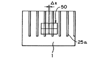
図2は図1に示した塗布装置をX軸方向から見た塗布ヘッド18周辺をあらわしている。Zスライドテーブル13に取り付けられているカメラ22にて基板1の中の代表となる凹部21を撮像し、画像位置処理部23を介してX軸位置制御部24にてXスライドテーブル4を移動し、代表となる凹部21の中央と該代表となる凹部21に対応する塗布ヘッド18の中の代表となるノズル孔18aの中央がほぼ一致するよう制御される。つまり、図3に示すように、基板1の代表となる凹部21の画像と画像処理のカーソル50の中央との差異ΔXをXスライドテーブル4をX軸方向に移動して補正するようになっている。
【0023】
なお、上記代表となる凹部21は、凹部配列方向中央の凹部21である。また、代表となるノズル孔18aは、その配列方向中央のノズル孔18aである。代表となる凹部21および代表となるノズル孔18aをそれぞれその配列方向中央の凹部21、ノズル孔18aに設定すれば、配列方向端部における凹部21とノズル孔18aとの中央の位置ずれを最小限に抑制することができる。
【0024】
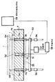
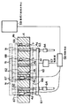
図4は、図1に示した塗布装置の塗布ヘッド18への塗液の供給制御装置の概略縦断面図である。図4において、塗布ヘッド18は、筐体31からなり、筐体31の下面板32には、多数個の塗液を吐出するノズル孔18aが、一列に所定の間隔をもって穿設されている。筐体31の内部の空間33は、塗液30(蛍光体ペースト27)が貯留される塗液貯留部34とその上部に位置する気体空間35から形成されている。筐体31の上面板36には、気体圧力導通孔37が設けられ、気体圧力導通孔37には、管路からなる気体圧力導通路38の一端が連結されている。気体圧力導通路38の他端は、設定圧に維持された圧力を有する気体圧力源40に開口されている。気体圧力導通路38には、方向切替弁からなる開閉手段39が設けられ、開閉手段39の開閉切り替えにより、気体空間35と気体圧力源40との連通と遮断が行われる。開閉手段39は各塗布ヘッドの18のノズル孔18aの位置と基板1の相対位置を検出し、開閉手段39のタイミングを制御する図示しない位置検出、吐出制御手段にて開閉のタイミングが制御されるようになっている。なお、本実施態様においては、ペースト27はR(赤色)、G(緑色)、B(青色)のうち、いずれか一色が塗布されるようになっている。
【0025】
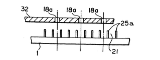
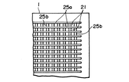
図5は、基板1上に形成された凹部21を上面から見た詳細である。1面目の凹部21に蛍光体ペースト27が充填されており、塗液の塗布方向に延びる複数の縦リブ25aの間に所定のピッチでストライプ状に形成される凹部21は表示部の端部でとぎれ非表示部26には形成されていない。本実施態様においては、図6に示すように同一色の塗液が2つおきの凹部21に塗布できるようになっている。したがって、ノズル孔18aのピッチは、縦リブ25aのピッチの3倍になっている。なお、基板1としては、図7に示すように縦リブ25aと該縦リブ25aに直交する方向に延びる複数の横リブ25bにより格子状に形成される凹部21を有するものであってもよい。
【0026】
本実施態様においては図8に示すようにXスライドテーブル4の下方には、Xスライドテーブル4の基板載置面4a上に基板1を載置するとともに面4aから基板1を離間させる基板昇降手段53と、該手段53のピン54上または面4a上の基板1の有無を検知する基板検知手段51が設けられている。基板検知手段51の検出ヘッド部52(本実施態様では光ファイバ光電センサ)は、テーブル4の厚さ方向に貫通する検出孔4cに内挿されており、該検出孔4cを介して基板1を検知するようになっている。検出ヘッド部52は面4aよりも下になるようにXスライドテーブル4に内挿されている。なお、図8においては、基板検知手段51はXスライドテーブル4に内挿されているが、本発明では基板昇降手段53に支持される。例えば、図9に示すように基板検知手段51は基板昇降手段53と一体に構成することも可能である。図9においては、基板検知手段51の検出ヘッド部52は基板昇降手段53の支持部材55に部材60を介して支持されており、基板昇降手段53の上昇、降下に伴って上下方向に移動するようになっている。つまり、基板昇降手段53が降下した状態においては、検出ヘッド部52は検出孔4cに内蔵され面4aよりも下に位置しているが、基板昇降手段53が上昇した際には、検出ヘッド部52は面4aから突出するようになっている。このように、検出ヘッド部52を移動可能に構成すれば、検出ヘッド部52と基板1との間隔を常に一定に保つことができるので、基板検知の信頼性を向上することができる。
【0027】
基板昇降手段53は、複数のピン54と該ピン54を支持する支持部材55と、該支持部材55の昇降をガイドするガイド手段56および駆動源57とを有している。駆動源57からの動力により部材55およびピン54が昇降するようになっている。ピン54が上昇しXスライドテーブル4の挿通孔4bを挿通され面4aよりも突出した状態で基板供給排出手段59から基板1がピン54上に供給されると、ピン54は次第に降下し、面4a上に基板1が載置される。また、基板1へのペースト27の塗布が終了した際には、再びピン54が上昇し面4aから基板1が離間されるようになっている。そして、塗布が終了し面4aから離間された基板1は基板供給排出手段59により次工程(たとえば、他色の塗布工程等)に送られるようになっている。
【0028】
また、基板昇降手段53はXスライドテーブル4とともにX軸方向にスライド可能になっている。基板昇降手段53の駆動源57の駆動・停止は制御手段58により制御されるようになっている。
【0029】
制御手段58には、基板検知手段51からの基板検知信号が送られるようになっている。また、制御手段58には、塗布ヘッド18のX軸、Y軸方向の位置信号が送信されるようになっている。基板昇降手段53が上昇した際に、ピン54または基板1と塗布ヘッド18が干渉し合う位置関係にある場合には、基板昇降手段53の上昇が禁止されるようになっている。このため、とくに面4a上に基板1が載置され塗布ヘッド18によるペースト27の塗布が行われている途中に基板昇降手段53が誤って上昇するような不具合が確実に防止されるようになっている。
【0030】
また、制御手段58は上記基板供給排出手段59の制御も司るようになっている。そして、上記と同様に面4a上またはピン54上の基板1の存在が検知されている際には、ピン54上への新たな基板1の供給が停止されるようになっている。
【0031】
本実施態様の塗液の塗布装置および方法においては、Xスライドテーブル4上または基板昇降手段53上の基板1の有無を検知する基板検知手段51が設けられているので、Xスライドテーブル4上等における基板1の存在を確実に検知することができる。そして、Xスライドテーブル4上等に基板1が存在する場合には、基板供給排出手段59による新たな基板1の供給が禁止されるので、Xスライドテーブル4上等に基板1が存在するにもかかわらず新たな基板1を供給する誤作動を確実に防止できる。また、基板昇降手段53の上昇時に基板1等と塗布ヘッド18が干渉し合う位置にある場合には、基板昇降手段53の上昇が禁止されるので、塗布ヘッド18によるペースト27の塗布中に基板昇降手段53が誤って上昇し、基板1と塗布ヘッド18とが衝突する不都合を確実に防止することができる。
【0032】
また、本実施態様においては、基板検知手段1の検出ヘッド部52は検出孔4c内に内挿されている。つまり、面4aよりも下に設けられているので、たとえば受光部等を面4aよりも上方に設ける必要のあった従来装置に比べて装置の小型化を促進することができる。
【0033】
なお、本実施態様においては、検出ヘッド部52は光ファイバ光電センサが用いられているが、たとえばCCDカメラを用いることも可能である。
【0034】
図10、図11は、本発明の第2実施態様に係る塗液の塗布装置を示している。なお、上記第1実施態様と同一の部材には同一の番号を付しその説明を省略することとする。本実施態様においては、Xスライドテーブル4の下方には基板昇降手段61が設けられている。基板昇降手段61は、ピン62と、該ピン62を支持する支持部材63と、該支持部材63を昇降させる駆動源57と、支持部材63の昇降をガイドするガイド手段64を有している。駆動源65からの動力により、支持部材63が昇降するとXスライドテーブル4の挿通孔4bに挿通されたピン62が昇降するようになっている。
【0035】
Xスライドテーブル4の検出孔4d、4e、4f、4gには、基板検知手段66の検出ヘッド部として光ファイバ光電センサ67またはCCDカメラ68が内挿されている。センサ67は部材60により基板昇降手段61の支持部材63に支持されている。昇降手段61が降下した際にはセンサ67は検出孔4d、4eに内蔵され面4cよりも下に位置するようになっている。一方、昇降手段61が上昇した際にはセンサ67は、面4cよりも上に突出するようになっている。
【0036】
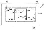
また、検出孔4d、4gは、大型基板1aが正しくテーブル4上に載置された場合にアライメントマーク69が存在する直下に対応する位置、一方、検出孔4e、4fは小型基板1bのアライメントマーク70の直下に対応する位置に穿設されている。
【0037】
したがって、本実施態様においては、Xスライドテーブル4上に載置される基板が大型基板1aである場合には、検出孔4g内のカメラ68により基板1aの有無およびアライメントマーク69が検出されるとともに検出孔4d、4e内のセンサ67および検出孔4f内のCCDカメラ68により基板1aの有無が検知される。一方、Xスライドテーブル4上に載置される基板が小型基板1bである場合には、4e内のセンサ67により基板1bの有無が検出されるとともに、4f内のCCDカメラ68により基板1bの有無とアライメントマーク70が検出されるようになっている。なお、センサ67、カメラ68による検出信号は、逐次制御手段58に送られ、上記第1実施態様と同様に駆動源57、基板供給排出手段59が制御されるようになっている。
【0038】
本実施態様においても、上記第1実施態様の作用に準じて、装置の誤作動を防止しつつ、装置の小型化を促進することができる。また、本実施態様においては、カメラ68がアライメントマーク検出手段として機能している。つまり、基板検知手段61によりアライメントマークの検出が可能になっている。このように基板検知とアライメントマークの検出を同時に行うようにすれば装置のタクトタイムのロスを大幅に抑制できる。さらに、本実施態様においては、サイズの異なる基板1a、1bの検知が可能になっているが、これは検出孔4c内に検出ヘッド部を内挿する本願発明を実施することにより得られる優れた効果である。たとえば、従来装置において、サイズの異なる2種以上の基板を検知しようとする際には複数のセンサをテーブルの上方に配設する必要があるが、スペース的な制約から極めて困難になるからである。
【0039】
【発明の効果】
以上説明したように、本発明の塗液の塗布装置および方法によるときは、装置の大型化を防止しつつ、テーブル上または基板昇降手段上における基板の有無を確実に検知することができる。また、テーブル上等に基板が存在する場合には新たな基板の供給が停止されるので、装置トラブルや不良基板の発生を防止することができる。さらに、基板昇降手段の上昇時に塗布ヘッドと基板等とが干渉し合う位置にある場合には、基板昇降手段の上昇が禁止されるので、塗布ヘッドと基板昇降手段との衝突を防止でき、誤作動による装置の破損のおそれを解消することができる。
【0040】
また、基板検知手段はサイズの異なる2種以上の基板の有無を検知することもできるので、異種サイズの基板の混入による塗布不良や装置の誤作動を防止することができる。また、基板検知手段に、アライメントマークの検出機能を付与すれば、基板の検知とアライメントマークの検出を同時に行うことができるので、装置のタクトタイムのロスを低減し大幅に生産性を向上することができる。
【図面の簡単な説明】
【図1】本発明係る塗液の塗布装置の斜視図である。
【図2】図1に示した塗布装置をX軸方向から見た塗布ヘッド周辺の概略図である。
【図3】凹部の画像と画像処理のカーソルを示す概略図である。
【図4】図1に示した塗布装置の塗布ヘッドへの塗液の供給制御装置の概略縦断面図である。
【図5】基板上の凹部を上面から見た概略図である。
【図6】ノズル孔と凹部の位置関係を示す概略図である。
【図7】図5とは別の態様の基板の平面図である。
【図8】第1の装置の基板検知手段の概略構成図である。
【図9】 図8の装置において基板検知手段が基板昇降手段に支持される一形態を示した概略構成図である。
【図10】本発明の第2実施態様に係る塗液の塗布装置の基板検知手段の概略構成図である。
【図11】図9の装置のテーブルの平面図である。
【符号の説明】
1 被塗布基板
1a 大型基板
1b 小型基板
2 機台
3a、3b Xスライドレール
4 Xスライドテーブル
4a 基板載置面
4b 挿通孔
4c 検出孔
5 駆動軸
6 X軸モータ
7 支持機台
7a 側面
8a、8b Yスライドレール
9 Yスライドテーブル
10 駆動軸
11 Y軸モータ
12a、12b Zスライドレール
13 Zスライドテーブル
14 駆動軸
15 Z軸モータ
16 センサ支持軸
17 位置センサ
18 塗布ヘッド
18a ノズル孔
19 塗着ストライプ
20 Y軸方向速度制御手段
21 凹部
22 カメラ
23 画像位置処理部
24 X軸位置制御部
25a 縦リブ
25b 横リブ
26 非表示部
27 蛍光体ペースト
29a 第1の移動手段
29b 第2の移動手段
30 塗液
31 筺体
32 下面板
33 空間
34 塗液貯留部
35 気体空間
36 上面板
37 気体圧力導通孔
38 気体圧力導通路
39 開閉手段
40 気体圧力源
41 Z軸方向位置制御手段
50 カーソル
51、66 基板検知手段
52 検出ヘッド部
53、61 基板昇降手段
54、62 ピン
55、63 支持部材
56、64 ガイド手段
57、65 駆動源
58 制御手段
59 基板供給排出手段
60 部材
67 光ファイバ光電センサ
68 CCDカメラ
69、70 アライメントマーク[0001]
BACKGROUND OF THE INVENTION
The present invention relates to a coating liquid coating apparatus and method for coating a coating liquid on, for example, a recess formed in a stripe shape on the surface of a substrate, and more particularly to a manufacturing apparatus and a method for a light emitting substrate for a plasma display.
[0002]
[Prior art]
Conventionally, as a substrate placed on a table and coated with a coating liquid, for example, there are a light emitting substrate for plasma display and a light emitting substrate for LCD. In light emitting substrates for plasma displays, a plurality of vertical ribs extending in the coating direction are formed on the surface of the substrate, and in recent years, in order to meet demands for improving brightness and contrast and reducing power consumption, a lattice-like surface is formed on the substrate surface. Substrates having recesses are also employed (for example, Japanese Patent Application Laid-Open Nos. 11-213896 and 2000-123747). As an apparatus for applying a coating solution to a substrate placed on a table, a device as described in JP-A-11-274274 is known. Further, as an alignment mark detection means for confirming the position of a substrate in a coating apparatus or the like, generally, the upper surface side of the substrate, that is, the substrate detection method of the substrate detection device of JP-A-5-294405, that is, The mark detecting means is arranged from the coating liquid application surface toward the table side.
[0003]
[Problems to be solved by the invention]
However, in an apparatus such as that disclosed in Japanese Patent Application Laid-Open No. 11-274274, it is possible to detect the substrate on the pins of the substrate raising / lowering means, but not to detect the substrate on the table, and the substrate detecting means is a light emitting / receiving type. Therefore, it is necessary to provide a light receiving part or a light projecting part above the substrate. In particular, since an application head and a mechanism for operating them are provided above the substrate, the arrangement of the substrate detection means above the substrate may increase the size of the apparatus. Further, when malfunctioning or the like, there is a concern about interference with the coating head, which may cause damage to the apparatus.
[0004]
Also, regarding the type of board size, the operator only knows the type of board size currently being put in. If a board of another type is thrown in due to some mistake, for example, When a large-sized substrate is mistakenly applied to apply a coating liquid to a small-sized substrate, an area where no coating liquid is applied appears.
[0005]
On the other hand, the alignment mark detection unit is also concerned about interference with the coating head, and after a series of operations, the substrate is placed on the table, and the suction unit sucks the substrate, and then the mark detection unit is attached to the substrate. The operation goes to detect the marked mark. Therefore, the time taken for the mark detection means to detect the mark attached to the substrate is a loss of tact time of the apparatus, and improvement in productivity cannot be expected.
[0006]
The object of the present invention is to reliably detect the presence or absence of a substrate on a table or a substrate lifting means while preventing an increase in the size of the device, and to detect an alignment mark on the surface of the substrate to prevent malfunction of the device. It is another object of the present invention to provide a coating liquid coating apparatus and method and a plasma display member manufacturing apparatus and method capable of improving productivity.
[0007]
[Means for Solving the Problems]
In order to solve the above problems, a coating liquid coating apparatus of the present invention includes a table for adsorbing and fixing a substrate to which a coating liquid is applied, a coating head for applying the coating liquid to the substrate at a position facing the substrate, Detection of penetrating through the table in the thickness direction in a coating liquid coating apparatus comprising: a moving means for moving the table and the coating head relative to each other; and a substrate lifting / lowering means for placing the substrate on the table and separating the substrate from the table. A hole is formed, and a detection head portion of a substrate detection means for detecting the presence or absence of a substrate on the table or the substrate lifting means is inserted into the detection hole, and the detection head portion of the substrate detection means is supported by the substrate lifting means The detection head portion is configured to be movable up and down together with the substrate lifting means .
[0010]
As described above, the detection head portion of the substrate detection means is supported by the substrate lifting / lowering means . That is, when the substrate lifting / lowering means is lowered, the detection head portion is installed in the detection hole of the table, and when the substrate lifting / lowering means is raised, the detection hole protrudes from the substrate mounting surface of the table. It can be configured to. In this case, since the distance between the substrate and the detection head unit can be kept constant at all times, the reliability of the presence / absence detection of the substrate can be improved.
[0012]
For example, a CCD camera, an optical fiber photoelectric sensor, or the like can be used as the detection head portion of the substrate detection means. The substrate is generally transparent glass (including colorless and transparent, colored and transparent, colorless and translucent, and colored and translucent). Therefore, if a CCD camera is used as the detection head unit, the alignment mark can be detected even from the side opposite to the coating surface of the substrate, so that the substrate detection means can be provided with an alignment mark detection function. On the other hand, if a CCD camera is used for the detection head portion of the alignment mark detection means, the presence / absence of the substrate can be detected together with the detection of the alignment mark, so that the substrate detection function can be provided to the alignment mark detection means. If the substrate detection means is provided with the alignment mark detection function as described above, or if the alignment mark detection means is provided with the substrate detection function, the substrate detection and the alignment mark detection can be performed simultaneously. Loss can be greatly reduced and productivity can be improved.
[0013]
In order to solve the above problems, a coating liquid coating method of the present invention includes a step of moving the substrate onto a table, a step of supporting the substrate by a substrate lifting / lowering means, and placing the substrate on the table, A step of detecting a substrate by a detection head unit of a substrate detection unit; and a step of applying a coating liquid on the substrate by a coating head disposed at a position facing the substrate, the detection head unit comprising: It is arranged on the table side with respect to the substrate, and is lifted and lowered together with the lifting and lowering means of the substrate.
Further, when the substrate lifting means is raised, if the means and the coating head are in a positional relationship where they interfere with each other, the raising of the substrate lifting means may be stopped .
[0016]
Further, in the coating liquid application method as described above, the presence or absence of the substrate on the table or the substrate lifting / lowering means is detected, and when the substrate exists, the supply of a new substrate by the substrate supply means is stopped. Therefore, the malfunction of the apparatus can be prevented and the generation of defective substrates can be surely prevented.
[0017]
DETAILED DESCRIPTION OF THE INVENTION
Hereinafter, preferred embodiments of the present invention will be described with reference to the drawings.
FIG. 1 is a perspective view of a coating liquid coating apparatus according to a first embodiment of the present invention. This coating apparatus is an apparatus that forms a plurality of rows of striped coating liquid coating portions in a predetermined direction on the surface of a
[0018]
Above the machine base 2, a gate-type support machine base 7 is provided so as to straddle the machine base 2. The support machine base 7 has
[0019]
On the Y slide table 9,
[0020]
An
[0021]
The
[0022]
FIG. 2 shows the periphery of the
[0023]
The
[0024]
FIG. 4 is a schematic longitudinal sectional view of the supply controller for supplying the coating liquid to the
[0025]
FIG. 5 shows details of the
[0026]
In the present embodiment, as shown in FIG. 8, below the X slide table 4, a substrate lifting means for placing the
[0027]
The substrate lifting / lowering means 53 includes a plurality of
[0028]
The substrate lifting / lowering means 53 is slidable in the X-axis direction together with the X slide table 4. Driving / stopping of the driving
[0029]
A substrate detection signal from the substrate detection means 51 is sent to the control means 58. Further, a position signal of the
[0030]
The control means 58 also controls the substrate supply / discharge means 59. As described above, when the presence of the
[0031]
In the coating liquid coating apparatus and method of the present embodiment, the substrate detecting means 51 for detecting the presence or absence of the
[0032]
Moreover, in this embodiment, the
[0033]
In this embodiment, an optical fiber photoelectric sensor is used as the
[0034]
10 and 11 show a coating liquid coating apparatus according to a second embodiment of the present invention. In addition, the same number is attached | subjected to the member same as the said 1st embodiment, and the description is abbreviate | omitted. In this embodiment, a substrate lifting / lowering means 61 is provided below the X slide table 4. The substrate lifting means 61 includes a
[0035]
In the
[0036]
The detection holes 4d and 4g correspond to positions immediately below where the
[0037]
Therefore, in this embodiment, when the substrate placed on the X slide table 4 is the large substrate 1a, the presence or absence of the substrate 1a and the
[0038]
Also in this embodiment, according to the effect | action of the said 1st embodiment, size reduction of an apparatus can be accelerated | stimulated, preventing the malfunctioning of an apparatus. In this embodiment, the
[0039]
【The invention's effect】
As described above, according to the coating liquid coating apparatus and method of the present invention, it is possible to reliably detect the presence or absence of the substrate on the table or the substrate lifting means while preventing the apparatus from becoming large. In addition, when a substrate is present on a table or the like, supply of a new substrate is stopped, so that it is possible to prevent device troubles and occurrence of defective substrates. Further, if the coating head and the substrate, etc. are in a position where they interfere with each other when the substrate lifting means is raised, the raising of the substrate lifting means is prohibited, so that the collision between the coating head and the substrate lifting means can be prevented. The risk of damage to the device due to operation can be eliminated.
[0040]
In addition, since the substrate detection means can detect the presence or absence of two or more types of substrates having different sizes, it is possible to prevent application failure and malfunction of the apparatus due to mixing of substrates of different sizes. Moreover, if the detection function of the alignment mark is added to the substrate detection means, the detection of the substrate and the detection of the alignment mark can be performed at the same time, so the loss of the tact time of the apparatus is reduced and the productivity is greatly improved. Can do.
[Brief description of the drawings]
FIG. 1 is a perspective view of a coating liquid coating apparatus according to the present invention.
FIG. 2 is a schematic view of the periphery of a coating head when the coating apparatus shown in FIG. 1 is viewed from the X-axis direction.
FIG. 3 is a schematic diagram showing an image of a recess and a cursor for image processing.
4 is a schematic longitudinal sectional view of a supply controller for supplying a coating liquid to a coating head of the coating apparatus shown in FIG. 1. FIG.
FIG. 5 is a schematic view of a recess on a substrate as viewed from above.
FIG. 6 is a schematic view showing a positional relationship between nozzle holes and recesses.
7 is a plan view of a substrate according to another embodiment different from FIG. 5; FIG.
FIG. 8 is a schematic configuration diagram of substrate detection means of the first apparatus.
FIG. 9 is a schematic configuration diagram showing an embodiment in which the substrate detection means is supported by the substrate lifting means in the apparatus of FIG . 8;
FIG. 10 is a schematic configuration diagram of a substrate detection unit of a coating liquid coating apparatus according to a second embodiment of the present invention.
11 is a plan view of a table of the apparatus of FIG. 9. FIG.
[Explanation of symbols]
DESCRIPTION OF SYMBOLS 1 Substrate to be coated 1a Large substrate 1b Small substrate 2 Machine base 3a, 3b X slide rail 4 X slide table 4a Substrate mounting surface 4b Insertion hole 4c Detection hole 5 Drive shaft 6 X axis motor 7 Support machine base 7a Side surface 8a, 8b Y slide rail 9 Y slide table 10 Drive shaft 11 Y axis motors 12a, 12b Z slide rail 13 Z slide table 14 Drive shaft 15 Z axis motor 16 Sensor support shaft 17 Position sensor 18 Application head 18a Nozzle hole 19 Application stripe 20 Y Axial speed control means 21 Recess 22 Camera 23 Image position processing section 24 X-axis position control section 25a Vertical rib 25b Horizontal rib 26 Non-display part 27 Phosphor paste 29a First moving means 29b Second moving means 30 Coating liquid 31 Housing 32 Lower surface plate 33 Space 34 Coating liquid reservoir 35 Gas space 36 Upper surface plate 37 Gas pressure Through hole 38 Gas pressure conduction path 39 Opening / closing means 40 Gas pressure source 41 Z-axis direction position control means 50 Cursor 51, 66 Substrate detection means 52 Detection head portion 53, 61 Substrate elevating means 54, 62 Pin 55, 63 Support member 56, 64 Guide means 57, 65 Drive source 58 Control means 59 Substrate supply / discharge means 60 Member 67 Optical fiber photoelectric sensor 68 CCD camera 69, 70 Alignment mark
Claims (1)
前記基板と対向する位置において基板に塗布する塗布ヘッドと、
前記テーブルと塗布ヘッドを相対移動する移動手段と、
前記基板テーブル上に載置するとともにテーブル上から離間させる基板昇降手段とを有する塗布液の塗布装置において、
前記テーブルに厚み方向に貫通する検出孔を形成するとともに、該検出孔に、テーブル上または基板昇降手段上の基板の有無を検知する基板検知手段の検出ヘッド部を内挿し、前記基板検知手段の検出ヘッド部を基板昇降手段に支持させ、該検出ヘッド部を基板昇降手段とともに昇降可能に構成したことを特徴とする塗液の塗布装置。A table for adsorbing and fixing the substrate to which the coating liquid is applied;
An application head for applying to the substrate at a position facing the substrate;
Moving means for relatively moving the table and the coating head;
In a coating liquid coating apparatus having substrate lifting and lowering means placed on the substrate table and separated from the table,
A detection hole penetrating in the thickness direction is formed in the table, and a detection head portion of a substrate detection means for detecting the presence or absence of a substrate on the table or the substrate lifting / lowering means is inserted into the detection hole, and the substrate detection means A coating liquid coating apparatus, wherein the detection head unit is supported by a substrate lifting / lowering unit, and the detection head unit can be lifted / lowered together with the substrate lifting / lowering unit.
Priority Applications (1)
| Application Number | Priority Date | Filing Date | Title |
|---|---|---|---|
| JP2000383508A JP4765166B2 (en) | 2000-12-18 | 2000-12-18 | Coating liquid application equipment |
Applications Claiming Priority (1)
| Application Number | Priority Date | Filing Date | Title |
|---|---|---|---|
| JP2000383508A JP4765166B2 (en) | 2000-12-18 | 2000-12-18 | Coating liquid application equipment |
Publications (3)
| Publication Number | Publication Date |
|---|---|
| JP2002177861A JP2002177861A (en) | 2002-06-25 |
| JP2002177861A5 JP2002177861A5 (en) | 2008-02-07 |
| JP4765166B2 true JP4765166B2 (en) | 2011-09-07 |
Family
ID=18851153
Family Applications (1)
| Application Number | Title | Priority Date | Filing Date |
|---|---|---|---|
| JP2000383508A Expired - Fee Related JP4765166B2 (en) | 2000-12-18 | 2000-12-18 | Coating liquid application equipment |
Country Status (1)
| Country | Link |
|---|---|
| JP (1) | JP4765166B2 (en) |
Families Citing this family (3)
| Publication number | Priority date | Publication date | Assignee | Title |
|---|---|---|---|---|
| JP2010171172A (en) * | 2009-01-22 | 2010-08-05 | Eisaku Hibi | Component holding tool, and negative pressure sucking device using the component holding tool |
| JP6765926B2 (en) * | 2016-10-07 | 2020-10-07 | 株式会社ディスコ | Processing equipment |
| CN106733495A (en) * | 2016-12-22 | 2017-05-31 | 重庆淳祥电子科技有限公司 | A kind of conveyer with fuel feeding ink system |
Family Cites Families (4)
| Publication number | Priority date | Publication date | Assignee | Title |
|---|---|---|---|---|
| JPH09252043A (en) * | 1996-03-14 | 1997-09-22 | Nikon Corp | Positioning method |
| JP3646747B2 (en) * | 1995-11-28 | 2005-05-11 | 東レ株式会社 | COATING APPARATUS, COATING METHOD, COLOR FILTER MANUFACTURING APPARATUS AND ITS MANUFACTURING METHOD |
| JPH10233163A (en) * | 1996-12-17 | 1998-09-02 | Toray Ind Inc | Method and device for manufacturing plasma display |
| JPH1157533A (en) * | 1997-08-14 | 1999-03-02 | Able:Kk | Coating nozzle for thin film forming device and thin film forming device using the coating nozzle |
-
2000
- 2000-12-18 JP JP2000383508A patent/JP4765166B2/en not_active Expired - Fee Related
Also Published As
| Publication number | Publication date |
|---|---|
| JP2002177861A (en) | 2002-06-25 |
Similar Documents
| Publication | Publication Date | Title |
|---|---|---|
| JP3584732B2 (en) | Dispensing device, dispensing method and dispensing tip mounting method | |
| KR100515908B1 (en) | Positioning device for processing substrate and transfer device for processing substrate thereon | |
| KR100886988B1 (en) | Probe card carrier and method of carrying probe card | |
| JP2006261325A (en) | Device for holding electronic component, system and method for mounting electronic component | |
| WO2015151246A1 (en) | Component mounting machine | |
| JPH0767033B2 (en) | Automatic mounting device | |
| WO2018179317A1 (en) | Component mounter and mounting head | |
| KR20100052996A (en) | Round dispensing device for manufacturing camera module, camera module test apparatus comprising the same, and round dispensing method using the same | |
| JP4765166B2 (en) | Coating liquid application equipment | |
| KR101189884B1 (en) | Component mounting apparatus and method for determining component holding members | |
| KR20220017416A (en) | Mill pin device used in chip packaging | |
| KR100589234B1 (en) | Substrate treating apparatus for manufacturing flat panel display devices | |
| WO2012014467A1 (en) | Parts mounting apparatus and parts mounting method | |
| JP2010143085A (en) | Substrate supporting apparatus and screen printing machine | |
| KR100754476B1 (en) | Device for fabricating back light unit for lcd and method for controlling the same | |
| JP4743957B2 (en) | Coating liquid coating method and apparatus, and plasma display member manufacturing apparatus and manufacturing method | |
| JP5419641B2 (en) | Electronic component mounting apparatus and electronic component mounting method | |
| KR100697661B1 (en) | Notch aligner and method for aligning the notch | |
| CN114300404A (en) | Calibration device and calibration method | |
| KR20230132876A (en) | Bonding device and bonding method for display substrate | |
| JP3042190B2 (en) | Device and method for detecting displacement of electronic component suction nozzle | |
| JP4637423B2 (en) | Electrical component mounting device | |
| KR20190012462A (en) | Apparatus for transferring semiconductor substrate | |
| JPH08340198A (en) | Board positioning suction pin unit | |
| KR20080008787A (en) | Apparatus for assembling substrates |
Legal Events
| Date | Code | Title | Description |
|---|---|---|---|
| A521 | Written amendment |
Free format text: JAPANESE INTERMEDIATE CODE: A523 Effective date: 20071213 |
|
| A621 | Written request for application examination |
Free format text: JAPANESE INTERMEDIATE CODE: A621 Effective date: 20071213 |
|
| RD04 | Notification of resignation of power of attorney |
Free format text: JAPANESE INTERMEDIATE CODE: A7424 Effective date: 20100312 |
|
| A711 | Notification of change in applicant |
Free format text: JAPANESE INTERMEDIATE CODE: A711 Effective date: 20100319 |
|
| A977 | Report on retrieval |
Free format text: JAPANESE INTERMEDIATE CODE: A971007 Effective date: 20100531 |
|
| A131 | Notification of reasons for refusal |
Free format text: JAPANESE INTERMEDIATE CODE: A131 Effective date: 20100610 |
|
| A521 | Written amendment |
Free format text: JAPANESE INTERMEDIATE CODE: A523 Effective date: 20100730 |
|
| RD03 | Notification of appointment of power of attorney |
Free format text: JAPANESE INTERMEDIATE CODE: A7423 Effective date: 20100827 |
|
| RD04 | Notification of resignation of power of attorney |
Free format text: JAPANESE INTERMEDIATE CODE: A7424 Effective date: 20100906 |
|
| A131 | Notification of reasons for refusal |
Free format text: JAPANESE INTERMEDIATE CODE: A131 Effective date: 20110308 |
|
| A521 | Written amendment |
Free format text: JAPANESE INTERMEDIATE CODE: A523 Effective date: 20110420 |
|
| A01 | Written decision to grant a patent or to grant a registration (utility model) |
Free format text: JAPANESE INTERMEDIATE CODE: A01 Effective date: 20110517 |
|
| A61 | First payment of annual fees (during grant procedure) |
Free format text: JAPANESE INTERMEDIATE CODE: A61 Effective date: 20110530 |
|
| FPAY | Renewal fee payment (prs date is renewal date of database) |
Free format text: PAYMENT UNTIL: 20140624 Year of fee payment: 3 |
|
| LAPS | Cancellation because of no payment of annual fees |