JP2010143085A - Substrate supporting apparatus and screen printing machine - Google Patents
Substrate supporting apparatus and screen printing machine Download PDFInfo
- Publication number
- JP2010143085A JP2010143085A JP2008323008A JP2008323008A JP2010143085A JP 2010143085 A JP2010143085 A JP 2010143085A JP 2008323008 A JP2008323008 A JP 2008323008A JP 2008323008 A JP2008323008 A JP 2008323008A JP 2010143085 A JP2010143085 A JP 2010143085A
- Authority
- JP
- Japan
- Prior art keywords
- support
- hole
- pin
- pins
- supporting
- Prior art date
- Legal status (The legal status is an assumption and is not a legal conclusion. Google has not performed a legal analysis and makes no representation as to the accuracy of the status listed.)
- Pending
Links
Images

Classifications
-
- B—PERFORMING OPERATIONS; TRANSPORTING
- B41—PRINTING; LINING MACHINES; TYPEWRITERS; STAMPS
- B41F—PRINTING MACHINES OR PRESSES
- B41F15/00—Screen printers
- B41F15/14—Details
- B41F15/16—Printing tables
- B41F15/18—Supports for workpieces
-
- B—PERFORMING OPERATIONS; TRANSPORTING
- B41—PRINTING; LINING MACHINES; TYPEWRITERS; STAMPS
- B41F—PRINTING MACHINES OR PRESSES
- B41F15/00—Screen printers
- B41F15/14—Details
- B41F15/44—Squeegees or doctors
- B41F15/46—Squeegees or doctors with two or more operative parts
-
- H—ELECTRICITY
- H05—ELECTRIC TECHNIQUES NOT OTHERWISE PROVIDED FOR
- H05K—PRINTED CIRCUITS; CASINGS OR CONSTRUCTIONAL DETAILS OF ELECTRIC APPARATUS; MANUFACTURE OF ASSEMBLAGES OF ELECTRICAL COMPONENTS
- H05K3/00—Apparatus or processes for manufacturing printed circuits
- H05K3/10—Apparatus or processes for manufacturing printed circuits in which conductive material is applied to the insulating support in such a manner as to form the desired conductive pattern
- H05K3/12—Apparatus or processes for manufacturing printed circuits in which conductive material is applied to the insulating support in such a manner as to form the desired conductive pattern using thick film techniques, e.g. printing techniques to apply the conductive material or similar techniques for applying conductive paste or ink patterns
- H05K3/1216—Apparatus or processes for manufacturing printed circuits in which conductive material is applied to the insulating support in such a manner as to form the desired conductive pattern using thick film techniques, e.g. printing techniques to apply the conductive material or similar techniques for applying conductive paste or ink patterns by screen printing or stencil printing
Landscapes
- Engineering & Computer Science (AREA)
- Mechanical Engineering (AREA)
- Screen Printers (AREA)
- Supply And Installment Of Electrical Components (AREA)
- Manufacturing Of Printed Wiring (AREA)
Abstract
【課題】作業者によるピンの抜き差し作業を無くし、基板支持装置でのピンの選択を自動化すると共に、ピンの選択に要する時間を極力短縮し、印刷機の印刷運転の遅れを回避する。
【解決手段】支持ピン52を支持する支持ブロック51と、支持ピンを昇降させる上部及び下部エア供給路58、59、支持ピンに対して相対的に移動が可能であり、上昇した状態の支持ピン52を下から支持する支持ピンベース81と、上下方向に移動可能で、下降して所望の支持ピンを押し込む押込装置87とを設ける。
【選択図】図8
An object of the present invention is to eliminate pin insertion / removal work by an operator, to automate the selection of a pin in a substrate support device, to shorten the time required for pin selection as much as possible, and to avoid a delay in printing operation of a printing press.
A support block 51 for supporting a support pin 52, upper and lower air supply paths 58 and 59 for raising and lowering the support pin, and movable relative to the support pin. A support pin base 81 that supports 52 from below and a push-in device 87 that is movable in the vertical direction and that lowers and pushes in a desired support pin are provided.
[Selection] Figure 8
Description
本発明は、プリント基板を支持する複数の支持ピンを備えた基板支持装置、及びスクリーン上の塗布剤をスキージを移動させることにより基板支持装置の支持ピンに支持されたプリント基板上に塗布するスクリーン印刷機に関する。 The present invention relates to a substrate support device having a plurality of support pins for supporting a printed circuit board, and a screen for applying a coating agent on the screen onto a printed circuit board supported by the support pins of the substrate support device by moving a squeegee. It relates to a printing machine.
この種のスクリーン印刷機は、例えば特許文献1などに開示されており、略水平に配置されたθ軸ベースと、このθ軸ベースが略水平な平面内で回転するよう前記θ軸ベースの中心軸を回転可能に軸支する軸受けと、前記θ軸ベースの下面の縁部を摺動自在にする支持する複数個のθ軸ベース支持機構、前記θ軸ベース上に設けられた基板の支持機構とを備え、この支持機構の上部に位置するバックアップ機構(基板支持装置)は、プレートとこのプレートに多数形成された孔の何れかに装着される複数本のピンとから構成されている。
This type of screen printing machine is disclosed in, for example,
上述したバックアップ機構では、印刷する基板の機種毎にピンの位置を変更する必要があり、例えば作業者がプレートに対してピンの抜き差し作業を行うときには、作業が煩雑になるという問題が発生する。特に作業対象のピンの数が多数のときには、一層作業が煩雑になると共に、作業に要する時間も長くなり、印刷機による印刷運転が遅れるという問題も発生する。 In the backup mechanism described above, it is necessary to change the position of the pin for each type of substrate to be printed. For example, when an operator performs an insertion / removal operation of the pin with respect to the plate, there is a problem that the operation becomes complicated. In particular, when the number of pins to be worked is large, the work becomes more complicated, and the time required for the work becomes longer, resulting in a problem that the printing operation by the printing press is delayed.
そして、上述した作業者によるピンの抜き差し作業の問題、或いは作業時間の問題を極力解決するための支持ピンである下受けピンの設定機構が例えば特許文献2などに記載されている。この設定機構では、貫通孔に、上下動して突出可能に収容した下受けピンを、所定の間隔でXY方向に二次元配置したプリント基板下受け手段と、制御信号に基づいて駆動され下受けピンを突出させる選択ピンをX方向に配置した選択手段と、プリント基板下受け手段と選択手段の間に介在し、下受けピンと選択ピンが当接可能に形成した貫通孔をX方向一列に配置した設定板を総ての下受けピンに対応するようにY方向に複数配置した設定手段と、下受け手段と設定手段とを一括してY方向に所定間隔で駆動する駆動手段と、設定板をX方向に駆動する設定板駆動手段とを備え、下受ピンの突出及び非突出を設定する。
しかしながら、特許文献2に記載されているプリント基板の下受けピンを設定する機構では、特に作業対象のピンの数が多数のときには、下受け手段と前記設定手段とを一括してY方向に所定間隔で駆動する回数が多くなり、設定に要する時間も長くなり、印刷機での印刷が遅れるという問題も発生する。 However, in the mechanism for setting the receiving pins of the printed circuit board described in Patent Document 2, especially when the number of pins to be worked is large, the receiving means and the setting means are collectively set in the Y direction. The number of times of driving at intervals increases, the time required for setting increases, and there is a problem that printing on the printing press is delayed.
そこで本発明は、作業者によるピンの抜き差し作業を無くし、ピンの選択を自動化すると共に、ピンの選択に要する時間を極力短縮し、印刷機の印刷の遅れを回避することを目的とする。 SUMMARY OF THE INVENTION Accordingly, an object of the present invention is to eliminate pin insertion / removal work by an operator, automate pin selection, shorten the time required for pin selection as much as possible, and avoid printing delay of a printing press.
このため第1の発明は、プリント基板を支持する複数の支持ピンを備えた基板支持装置において、前記支持ピンを支持する支持ブロックと、前記支持ピンを昇降させる昇降手段と、前記支持ピンに対して相対的に移動が可能であり、上昇した状態の前記支持ピンを下から支持するベースと、上下方向に移動可能で、下降して所望の前記支持ピンを前記支持ブロック内に押し込む押込装置とを備えたことを特徴とする。 Therefore, according to a first aspect of the present invention, there is provided a substrate support apparatus including a plurality of support pins for supporting a printed circuit board, a support block for supporting the support pins, an elevating unit for moving the support pins up and down, and the support pins. A base that supports the support pin in a raised state from below, and a pushing device that can move in the vertical direction and pushes down the desired support pin into the support block. It is provided with.
第2の発明は、プリント基板を支持する複数の支持ピンを備えた基板支持装置において、前記支持ピンを支持する複数の支持孔が間隔を存して上下方向に形成された支持ブロックと、前記支持ピンを複数本同時に昇降させる昇降手段と、支持ブロックの上に設けられ、前記支持ピンに対して移動が可能であり、上昇した状態の前記支持ピンを下から支持するベースと、水平方向及び上下方向に移動可能で、下降して所望の前記支持ピンを前記支持孔内に押し込む押込装置とを備えたことを特徴とする。 According to a second aspect of the present invention, there is provided a substrate support device including a plurality of support pins for supporting a printed circuit board, wherein a plurality of support holes for supporting the support pins are formed in a vertical direction with a space therebetween, Elevating means for elevating a plurality of support pins simultaneously, a base provided on the support block, movable with respect to the support pins, and supporting the support pins in a raised state from below; a horizontal direction; And a pushing device that is movable in the vertical direction and descends to push the desired support pin into the support hole.
第3の発明は、プリント基板を支持する複数の支持ピンを備えた基板支持装置において、前記支持ピンを支持する複数の支持孔が間隔を存して上下方向に形成された支持ブロックと、前記支持ピンを複数本同時に昇降させる昇降手段と、支持ブロックの上に設けられ、前記支持ブックに対して水平方向に相対的に移動可能で前記支持ピンに対して接近し、上昇した状態の前記支持ピンの支持部を下から同時に支持するベースと、水平方向及び上下方向に移動可能で、下降して所望の前記支持ピンを前記支持孔内に押し込む押込装置とを備えたことを特徴とする。 According to a third aspect of the present invention, there is provided a substrate support apparatus including a plurality of support pins for supporting a printed circuit board, wherein a plurality of support holes for supporting the support pins are formed in a vertical direction with a space therebetween, Elevating means for elevating and lowering a plurality of support pins at the same time, and the support provided on the support block, movable in a horizontal direction relative to the support book, approaching the support pins, and raised It is characterized by comprising a base for simultaneously supporting the support portion of the pin from the bottom, and a pushing device that is movable in the horizontal direction and the vertical direction, and descends to push the desired support pin into the support hole.
第4の発明は、プリント基板を支持する複数の支持ピンを備えた基板支持装置において、水平方向にスライド自在に設けられ、前記支持ピンを支持する複数の支持孔が間隔を存して上下方向に形成され、前記支持孔は前記支持ブロックの上部に形成されて前記支持ピンを上下にスライド自在に支持する上部孔とこの上部孔の下に形成され前記上部孔より断面積が大きい下部孔とから成り、この下部孔の上部と下部とにエア供給路が連通した支持ブロックと、下部に設けられ前記下部孔内にて上下にスライドするスライド部と、このスライド部の上に形成されスライド部より断面積が小さく前記下部孔の側壁との間に空間が形成されると共に上昇により前記上部孔内に摺動して収まる下中間部とこの下中間部の上に形成され、断面積が前記下中間部より小さい中央部と、この中央部の上に形成され前記下中間部と断面形状が等しい上中間部と、この上中間部の上に形成され前記上中間部より断面積が小さく括れた延在部とを備えた支持ピンと、支持ブロックの上に設けられ、前記支持ピンに対応して形成され前記上中間部に対応した昇降部とこの昇降部から連続して形成され前記支持ピンが上昇した状態で前記上中間部の下端を支持する支持部と備えた複数の貫通孔が形成されたベースと、水平方向及び上下方向に移動可能で、下降して前記支持ピンを前記支持孔内に押し込む押込ヘッドとを備えた
ことを特徴とする。
According to a fourth aspect of the present invention, there is provided a substrate support apparatus including a plurality of support pins for supporting a printed circuit board, wherein the plurality of support holes are slidable in a horizontal direction, and the plurality of support holes for supporting the support pins are spaced vertically. The support hole is formed in the upper part of the support block and supports the support pin slidably up and down, and the lower hole is formed below the upper hole and has a larger cross-sectional area than the upper hole. A support block having an air supply path communicating with an upper portion and a lower portion of the lower hole, a slide portion that is provided in the lower portion and slides up and down in the lower hole, and a slide portion formed on the slide portion. A space is formed between the lower hole and the side wall of the lower hole, and a lower intermediate part that slides and fits in the upper hole by rising and is formed on the lower intermediate part. Lower middle A central portion smaller than the central portion, an upper intermediate portion formed on the central portion and having the same cross-sectional shape as the lower intermediate portion, and an extension formed on the upper intermediate portion and having a smaller cross-sectional area than the upper intermediate portion. And a support pin provided on the support block. The lift pin is formed corresponding to the support pin and corresponding to the upper intermediate portion. The lift pin is formed continuously from the lift portion. In this state, a base having a plurality of through-holes provided with a support portion that supports the lower end of the upper intermediate portion, and a horizontal and vertical movement is possible, and the support pin is lowered into the support hole. And a pushing head for pushing.
第5の発明は、プリント基板を支持する複数の支持ピンと、パターン孔が形成されたスクリーンと、移動することにより前記スクリーン上の塗布剤をプリント基板上に前記パターン孔を介して塗布するスキージとを備えたスクリーン印刷機において、前記支持ピンを支持する支持ブロックと、前記支持ピンを昇降させる昇降手段と、前記支持ピンに対して相対的に移動が可能であり、上昇した状態の前記支持ピンを下から支持するベースと、上下方向に移動可能で、下降して所望の前記支持ピンを前記支持孔内に押し込む押込装置とを備えた基板支持装置を有したことを特徴とする。
第6の発明は、プリント基板を支持する複数の支持ピンと、パターン孔が形成されたスクリーンと、移動することにより前記スクリーン上の塗布剤をプリント基板上に前記パターン孔を介して塗布するスキージとを備えたスクリーン印刷機において、前記支持ピンを支持する複数の支持孔が間隔を存して上下方向に形成された支持ブロックと、前記支持ピンを複数本同時に昇降させる昇降手段と、支持ブロックの上に設けられ、前記支持ピンに対して移動が可能であり、上昇した状態の前記支持ピンを下から支持するベースと、水平方向及び上下方向に移動可能で、下降して所望の前記支持ピンを前記支持孔内に押し込む押込装置とを備えた基板支持装置を有したことを特徴とする。
According to a fifth aspect of the present invention, there are provided a plurality of support pins for supporting the printed circuit board, a screen having a pattern hole formed therein, and a squeegee for applying the coating agent on the screen onto the printed circuit board through the pattern hole by moving. A support block that supports the support pin, lifting and lowering means that lifts and lowers the support pin, and is movable relative to the support pin, and the support pin in a raised state The substrate support device includes: a base that supports the substrate from below; and a pushing device that is movable in the vertical direction and descends to push the desired support pin into the support hole.
A sixth invention includes a plurality of support pins for supporting a printed circuit board, a screen having a pattern hole formed thereon, and a squeegee for applying the coating agent on the screen onto the printed circuit board through the pattern hole by moving. A plurality of support holes for supporting the support pins formed in a vertical direction at intervals, lifting means for simultaneously lifting and lowering the plurality of support pins, and A base provided on the base and capable of moving with respect to the support pin, supporting the support pin in a raised state from below, and movable in a horizontal direction and a vertical direction, and descending to the desired support pin And a pressing device that pushes the substrate into the support hole.
第7の発明は、プリント基板を支持する複数の支持ピンと、パターン孔が形成されたスクリーンと、移動することにより前記スクリーン上の塗布剤をプリント基板上に前記パターン孔を介して塗布するスキージとを備えたスクリーン印刷機において、前記支持ピンを支持する複数の支持孔が間隔を存して上下方向に形成された支持ブロックと、前記支持ピンを複数本同時に昇降させる昇降手段と、支持ブロックの上に設けられ、前記支持ブックに対して水平方向に相対的に移動可能で前記支持ピンに対して接近し、上昇した状態の前記支持ピンの支持部を下から同時に支持するベースと、水平方向及び上下方向に移動可能で、下降して所望の前記支持ピンを前記支持孔内に押し込む押込装置とを備えた基板支持装置を有したことを特徴とする。 According to a seventh aspect of the present invention, there are provided a plurality of support pins for supporting the printed circuit board, a screen having a pattern hole formed thereon, and a squeegee for applying the coating agent on the screen onto the printed circuit board through the pattern hole by moving. A plurality of support holes for supporting the support pins formed in a vertical direction at intervals, lifting means for simultaneously lifting and lowering the plurality of support pins, and A base that is provided on the base and is movable relative to the support book in the horizontal direction, approaches the support pins, and supports the support portions of the support pins in a raised state simultaneously from below; And a substrate support device provided with a pushing device that is movable in the vertical direction and descends to push the desired support pin into the support hole.
第8の発明は、請求項3又は7に記載の基板支持装置又はスクリーン印刷機において、前記支持ピンの下部には前記支持孔の側壁と接触するパッキンが設けられ、前記支持孔の下部と上部との何れか一方にエアを供給するエア供給源を備えたことを特徴とする請求項3又は7に記載の基板支持装置又はスクリーン印刷機。 According to an eighth aspect of the present invention, in the substrate support apparatus or the screen printing machine according to claim 3 or 7, a packing contacting the side wall of the support hole is provided at a lower portion of the support pin, and a lower portion and an upper portion of the support hole. The substrate support device or the screen printing machine according to claim 3, further comprising an air supply source that supplies air to any one of the above.
第9の発明は、プリント基板を支持する複数の支持ピンと、パターン孔が形成されたスクリーンと、移動することにより前記スクリーン上の塗布剤をプリント基板上に前記パターン孔を介して塗布するスキージとを備えたスクリーン印刷機において、水平方向にスライド自在に設けられ、前記支持ピンを支持する複数の支持孔が間隔を存して上下方向に形成され、前記支持孔は前記支持ブロックの上部に形成されて前記支持ピンを上下にスライド自在に支持する上部孔とこの上部孔の下に形成され前記上部孔より断面積が大きい下部孔とから成り、この下部孔の上部と下部とにエア供給路が連通した支持ブロックと、下部に設けられ前記下部孔内にて上下にスライドするスライド部と、このスライド部の上に形成されスライド部より断面積が小さく前記下部孔の側壁との間に空間が形成されると共に上昇により前記上部孔内に摺動して収まる下中間部とこの下中間部の上に形成され、断面積が前記下中間部より小さい中央部と、この中央部の上に形成され前記下中間部と断面形状が等しい上中間部と、この上中間部の上に形成され前記上中間部より断面積が小さく括れた延在部とを備えた支持ピンと、支持ブロックの上に設けられ、前記支持ピンに対応して形成され前記上中間部に対応した昇降部とこの昇降部から連続して形成され前記支持ピンが上昇した状態で前記上中間部の下端を支持する支持部と備えた複数の貫通孔が形成されたベースと、水平方向及び上下方向に移動可能で、下降して前記支持ピンを前記支持孔内に押し込む押込ヘッドとを備えた基板支持装置を有したことを特徴とする。 According to a ninth aspect of the present invention, there are provided a plurality of support pins for supporting the printed circuit board, a screen having a pattern hole formed thereon, and a squeegee for applying the coating agent on the screen onto the printed circuit board through the pattern hole by moving. A plurality of support holes that are slidable in the horizontal direction and that support the support pins are formed in the vertical direction at intervals, and the support holes are formed in the upper part of the support block. And an upper hole for slidably supporting the support pin up and down, and a lower hole formed below the upper hole and having a larger cross-sectional area than the upper hole, and an air supply path between the upper and lower portions of the lower hole Are connected to each other, a slide part provided at the lower part and sliding up and down in the lower hole, and a cross-sectional area formed on the slide part from the slide part. A space is formed between the side wall of the lower hole and a lower intermediate portion that is slidably accommodated in the upper hole by ascending, and is formed on the lower intermediate portion. A small central portion, an upper intermediate portion formed on the central portion and having the same cross-sectional shape as the lower intermediate portion, and an extended portion formed on the upper intermediate portion and having a smaller cross-sectional area than the upper intermediate portion And a support pin provided on the support block, formed in correspondence with the support pin and corresponding to the upper intermediate part, and continuously formed from the lift part and the support pin being raised And a base formed with a plurality of through holes provided with a support portion for supporting the lower end of the upper intermediate portion, and a push that is movable in the horizontal direction and the vertical direction and descends to push the support pin into the support hole And a substrate support device having a head. The features.
第10の発明は、請求項4又は9に記載の基板支持装置又はスクリーン印刷機において、前記支持ピンのスライド部には前記下部孔内壁と接するパッキンが設けられたことを特徴とする。 According to a tenth aspect of the present invention, in the substrate support apparatus or the screen printing machine according to the fourth or ninth aspect, a packing that contacts the inner wall of the lower hole is provided on the slide portion of the support pin.
第11の発明は、請求項4又は9に記載の基板支持装置又はスクリーン印刷機において、前記支持ブロック及び前記ベースは複数の前記支持ピン毎に複数に分割され、前記昇降手段或いは前記エア供給路は分割された各支持ブロック毎に設けられていることを特徴とする。 In an eleventh aspect of the present invention, in the substrate support apparatus or the screen printing machine according to claim 4 or 9, the support block and the base are divided into a plurality for each of the plurality of support pins, and the elevating means or the air supply path. Is provided for each of the divided support blocks.
第12の発明は、請求項1乃至11に記載の基板支持装置又はスクリーン印刷機において、前記ベースの上には、前記支持ピンに対応して孔が形成されたシートが設けられたことを特徴とする。 According to a twelfth aspect of the present invention, in the substrate support apparatus or the screen printing machine according to any one of the first to eleventh aspects, a sheet having holes formed corresponding to the support pins is provided on the base. And
本発明は、作業者によるピンの抜き差し作業を無くし、基板支持装置でのピンの選択を自動化すると共に、ピンの選択に要する時間を極力短縮し、印刷機での印刷の遅れを回避することができる。 The present invention eliminates the pin insertion / removal operation by the operator, automates the selection of the pins in the substrate support device, reduces the time required for the selection of the pins as much as possible, and avoids the delay in printing on the printing press. it can.
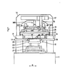
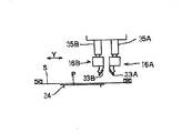
以下、本発明の具体的な実施形態を図面を参照しながら説明する。図1はスクリーン印刷機の要部の正面図、図2はスクリーン印刷機の要部の右側面図を示す。
図1に示すように、前記スクリーン印刷機1は、基台11上に設置された基板支持テーブル12と、この基板支持テーブル12の上方に配置されたスクリーン支持手段13と、基板支持テーブル12とスクリーン支持手段13の間に配置され基板支持テーブル12によって支持されたプリント基板Pに対角線上の位置に付された基板認識マークKMを撮像する第1撮像手段14と、スクリーン支持手段13の上方に配置されスクリーン支持手段13に支持されたスクリーンSに付されたスクリーン認識マークを撮像する第2撮像手段15と、スクリーンSの上方に配置された一対の印刷ヘッド16A、16B(図2参照)と、基板Pを基板支持テーブル12上に供給する供給コンベア17と、基板Pを基板支持テーブル12上から排出する排出コンベア18と、第1及び第2撮像手段14、15で撮像した画像を映し出す後述のモニタ47(図示せず)とを備えている。
前記基板支持テーブル12は、水平方向に延びるX軸の方向(図2参照)に移動するための第1移動機構21と、この第1移動機構21上に設けられ水平面内で回転するための回転機構22と、この回転機構22上に設けられ垂直方向に延びるZ軸の方向に移動するための第2移動機構23と、この第2移動機構(以下、ブロックベースという。)23上に設けられ後述する複数本の支持ピンとこれらの支持ピンを支持するブロック等を備えた基板支持装置24と、この基板支持装置24の上面に設けられ基板PをX軸方向に搬送する搬送機構(図示せず)とを備えている。
前記スクリーン支持手段13は、スクリーンSの下面の周縁部を支持するスクリーン支持枠25と、該スクリーン支持枠25の上方に配置されスクリーンSをスクリーン支持枠25に圧接するシリンダ26、26と、水平方向に延びるY軸の方向に移動するための移動機構27とを備えている。
前記第1撮像手段14は、基板認識カメラ28と、この基板認識カメラ28をX軸及びY軸方向に移動させる移動機構29と、基板支持テーブル12上の基板Pに光を照射する照明装置(図示せず)とを備えている。また、第2撮像手段15は、スクリーン認識カメラ31と、このカメラ31をX軸方向に移動させる移動機構32と、基板支持テーブル12上の基板Pに光を照射する照明装置(図示せず)とを備えており、カメラ31は印刷ヘッド16A、16Bの移動機構34によってY軸方向に移動するようになっている。
Hereinafter, specific embodiments of the present invention will be described with reference to the drawings. FIG. 1 is a front view of the main part of the screen printer, and FIG. 2 is a right side view of the main part of the screen printer.
As shown in FIG. 1, the
The substrate support table 12 has a
The screen support means 13 includes a
The first imaging means 14 includes a
なお、図2に示すように、印刷ヘッド16A、16BはY軸方向に間隔をおいて配置され、下端部にそれぞれスキージ33A、33Bが取り付けられており、前記移動機構34によって同時にY軸方向に移動すると共に垂直移動機構35A、35Bによってそれぞれ個別にZ軸方向に移動する。そして、印刷ヘッド16A、16Bが図2の左方向へ移動する際には右側の印刷ヘッド16Aが下降してスキージ33AがスクリーンS上を摺動し、図3の右方向へ移動する際には左側の印刷ヘッド16Bが下降してスキージ33BがスクリーンS上を摺動する。したがって、印刷ヘッド16A、16Bの一回の往復移動で二回の印刷処理が行われる。
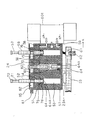
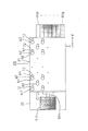
以下、上述した基板支持装置24について、図3及び図4に基づいて詳細に説明する。
As shown in FIG. 2, the print heads 16A and 16B are arranged at intervals in the Y-axis direction, and
Hereinafter, the above-described
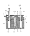
51は、支持ブロックであり、この支持ブロック51にはそれぞれが支持ピン52を支持する複数の支持孔53が等間隔で複数行(図1及び図2においてはX方向)、複数列(図2においてのY方向)、上下方向に形成されている。そして各支持孔53は、前記支持ブロック51の上部に形成されて前記支持ピン52を上下にスライド自在に支持する上部孔54とこの上部孔54の下に形成され上部孔54より断面積が大きい下部孔55とから成っている。また、支持ブロック51には、各行毎に下部孔55の上部と下部とのそれぞれを連通する上部エア供給路56及び下部エア供給路57が連通している。上部エア供給路56及び下部エア供給路57はそれぞれ上部吸入路58及び下部吸入路59に連通し、各上部吸入路58及び下部吸入路59のエア入り口は支持ブロック51の側面に支持孔53の各行毎に並んで取り付けられた例えばセンターオープンの5ポート電磁弁等の電磁弁60a〜60gに接続されている。
また、支持ブロック51とブロックベース23の間にはリニアガイド23aが複数個所に設けられ、支持ブロック51はブロックベース23の上に、水平方向(図3においてはX方向)にスライド自在に支持されている。ブロックベース23には電磁弁60a〜60gの近傍に接続孔61が形成され、この接続孔61の下部穴に図示しないエア供給源に接続されたエア供給パイプ62が接続され、位置決め孔61の上部穴には各電磁弁60a〜60gが配管接続されている。
Further,
ブロックベース23の上には支持ブロックをX方向(図4の矢印方向)に移動させるための駆動シリンダ63が設けられ、駆動シリンダ63のロッド63aが電磁弁60a〜60gと反対の支持ブロック51の側面に接続されている。
A
支持ピン52は、断面円形であり、その下部には、最も直径が大きく前記下部孔55内にて上下にスライドするスライド部64が形成されている。このスライド部64の下には、スライド部64より直径が小さい突出部64aが形成され、上にはスライド部64より直径が小さい括れ部65が形成されている。括れ部65は、その直径が上部孔54の直径より僅かに小さく支持ピン52の上昇により上部孔54内にほぼ収まる下中間部66と、この下中間部66の上に形成され、直径が下中間部66より小さい中央部(括れ)67と、この中央部67の上に形成され下中間部66と断面形状が等しい上中間部68とを備えている。そして、支持ピン52を下降させている状態で、括れ部65と下部孔55の側壁との間に空間70が形成されている。
The
更に、括れ部65の上には更に上方へ伸び中央部67と直径が等しく断面積が上中間部68より小さく括れている延在部71が形成され、この延在部71の上には延在部71より直径が大きい上端部72が形成されている。
Further, an
上述したスライド部64、括れ部65、延在部71及び上端部72は例えば一体に形成され、スライド部64の外周側面には全周に亘り溝75が形成され、溝75にパッキン76が取り付けられている。パッキン76は、例えば断面形状が下方に開放したU形状であり、スライド部64、即ち、支持ピン52の下方への移動時の抵抗は上方への移動時の抵抗より大きい。
The
81は、支持ブロック51の上に、支持ブロック51と間隔を存して設けられた支持ピンベースであり、各支持ピン52に対応して複数行、複数列、貫通孔82が形成されている。各貫通孔82は断面がだるま形状であり、直径が大きく上中間部68が昇降可能な昇降部83と、この昇降部83から連続して形成され支持ピン52が上昇した状態で上中間部68の下端を支持する直径が小さい支持部84とを備えている。なお、図4においては、総ての貫通孔の記載は省略する。
A
更に、支持ピンベース81の上方には塵埃をよけるためのシート85が設けられ、シート85には支持ピン52に対応して複数の孔86が形成されている。シート85は支持ブロック51と図示しない連結機構により連結され、支持ブロック51の移動に伴い支持ブロック51と同時に移動する。
Further, a
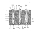
また、支持ブロック51の上方には、図7に示したように、XY方向、例えば水平方向に移動可能な押込装置であり、例えばシリンダである押込ヘッド87が設けられ、押込ヘッドには上下方向に移動可能で、下降して予め設置された支持ピン52を前記支持孔53内に押し込むロッド88が設けられている。
Further, as shown in FIG. 7, a pushing device that can move in the XY direction, for example, the horizontal direction, is provided above the
以下、印刷する基板に対応して各支持ピン52を設定するときの動作について、図3〜図12に基づいて説明する。なお、図5〜図12において、図示された各支持ピンを区別するために、最も左に位置した支持ピンから順に52a、52b及び52cとし、また、図3及び図4と同じ機構のものには同じ符号を付しその詳細な説明は省略する。
Hereinafter, the operation when setting each
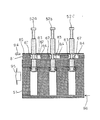
まず、各支持ピン52a、52b或いは52cによる基板支持の設定を開始する前の初期状態では、各支持ピン52a、52b及び52cは共に下降位置であり、スライド部64は、下部孔55の下部に位置し、突出部64aが下部孔55の底に当接し、括れ部65は上中間部68の上部を除き下部孔55内に位置し、支持ピン52a、52b及び52cと下部孔55の側壁との間に空間70が形成されている。また、中間部68の上部は上部孔54内に位置している。上部孔54の上方に貫通孔82が位置し、延在部71が貫通孔82を貫通し、上端部72がシート85の孔86に位置している。このような初期状態において、図示しないCPU等の制御装置が電磁弁60a〜60gに一方の開信号を出すると、電磁弁60a〜60gが動作する。そして、エア供給源から例えば電磁弁60aを介して矢印にて示したように、空気が対応した行の下部エア供給路57に送られ、各スライド部64には下方から圧力が加わり、各支持ピン52a、52b及び52cは上昇する。
First, in an initial state before starting the setting of substrate support by the support pins 52a, 52b or 52c, the support pins 52a, 52b and 52c are all in the lowered position, and the
この結果、図6に示したように、スライド部64の上面が下部孔55の上面に当接し、各支持ピン52a、52b及び52cは最も上昇した位置で停止する。このとき、下中間部66が上部孔54内にほぼ収まり、各支持ピン52a、52b及び52cが支持ブロック51の上部により支持され、また、中央部67は貫通孔82に対応した位置にある。そして、各支持ピン52a、52b及び52cのスライド部64のパッキン76により支持孔53内の空気の漏れが防止され、また、下部エア供給路57からの空気の供給が停止してもパッキン76と支持孔53の側壁との摩擦により各支持ピン52a、52b及び52cは上昇した位置に維持される(図3参照)。
As a result, as shown in FIG. 6, the upper surface of the
更に、上述したように、パッキン76の断面形状が下方に開放したU形状であり、スライド部64の下方への移動時の抵抗は上方への移動時の抵抗より大きいので、各支持ピン52a、52b及び52cを上昇させるときの空気圧力を極力小さくすることができ、また、各支持ピン52a、52b及び52cを上昇した状態に一層確実に維持することができる。
Furthermore, as described above, the cross-sectional shape of the packing 76 is a U shape opened downward, and the resistance when the
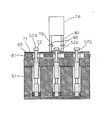
次に、下部エア供給路57からの空気の供給が停止し、図7に示したように、予め設定されたプリント基板を支持する必要がない支持ピン(以下、支持不要ピンという。)52bの上方へ移動していた押込ヘッド87のロッド88は下降する。
Next, the supply of air from the lower
この結果、ロッド88の下降によりその下端が支持ピン52bの上端部72に当接し、支持ピン52bが下降して図8に示したように支持ブロック51及び支持ピンベース81に押し込まれる。その後、押込ヘッド87は予め設定されているその他の支持不要ピンの上方へ移動し、同様に支持不要ピンを支持ブロック51及び支持ピンベース81に押し込む。支持ピンの押し込み時、下部エア供給路57は電磁弁を介して大気に開放され、支持ピンが押し込まれたときには、下部孔55内の空気は外部に押し出され、支持ピンをスムーズに押し込むことができる。
As a result, the lower end of the
総ての支持不要ピンの押し込み作業が終了すると、図9に矢印90に示したようにロッド88は上昇し、その状態に維持される。また、プリント基板の支持に使用される図示された支持ピン52a及び52cなどは上昇した状態に維持されている。次に、駆動シリンダ63が動作してロッド63aが伸び、支持ブロック51及びシート85が共に矢印91及び92の方向に次第に移動する。この移動に伴い、支持ピン52a及び52cの中央部67、即ち、プリント基板の支持に使用する支持ピンの中央部67は貫通孔82の昇降部83から支持部84へ移動する。また、支持ピン52bの延在部71、即ち、プリント基板の支持に使用しない支持ピンの延在部71も昇降部83から支持部84へ移動する。
When all of the push-in operations for the unsupported pins are completed, the
このように、支持ピン52a、52b及び52cなどには、支持ピン52a、52b及び52cが上昇している状態、或いは下降している状態で支持部84に対応して直径が小さい中央部67及び延在部71が形成されているので、各支持ピンが上昇している状態及び下降した状態の何れの状態においても、支持ブロック51の移動によって各支持ピンの中央部67及び延在部71を昇降部83から支持部84に移動させることできる。
As described above, the support pins 52a, 52b, and 52c include the
支持ブロック51及びシート85の移動が終了すると、次に、電磁弁60a〜60gが動作し、図10に矢印93に示したように、エア供給源から電磁弁60a〜60gを介して空気が上部エア供給路56に流れる。このため、空気の圧力により使用する支持ピンである支持ピン52a及び52c等がほぼ同時に僅かに下降し、図10に示したように、上中間部68の下端が支持ベース81の支持部84の周囲上面に当接し、その位置に支持される。このとき、支持ピン52a及び52c等の使用する支持ピンの中央部67が支持部84に嵌合するようにしてもよい。
When the movement of the
使用する支持ピン52a及び52c等の上中間部68の下端が支持ベース81の支持部84の周囲上面に当接し、その位置に支持されるので、支持ピン52a及び52cを含む使用する各支持ピンを支持ベース81により一斉に同じ高さ位置に位置決めすることができる。また、使用しない支持ピン52bなどは僅かに下降し、突出部64aが下部孔55の底面に当接して支持されて位置決めされる。
Since the lower end of the upper
このように、支持ピン52a及び52cなどをプリント基板の支持位置に設定するとき、即ち、位置決めするとき、駆動手段を用いて各支持ピンを一斉に上昇或いは下降させて位置決めするので、支持ピンの設定に必要な時間を極力短くすることができる。 Thus, when setting the support pins 52a and 52c to the support position of the printed circuit board, that is, when positioning, the support pins are positioned by raising or lowering all at once using the driving means. The time required for setting can be shortened as much as possible.
また、上述した支持ピンの設定は各電磁弁60b〜60gに対応した行毎に各支持ピンについても同様に行われる。各行の支持ピンのうちプリント基板支持に使用される支持ピンが位置決めされ、設定される。 Moreover, the setting of the support pin mentioned above is performed similarly about each support pin for every line corresponding to each electromagnetic valve 60b-60g. Of the support pins in each row, the support pins used for supporting the printed circuit board are positioned and set.
この結果、支持ピン52a及び52cなどの使用する支持ピンをプリント基板の支持位置に設定するとき、作業者が作業を行うことなく必要な支持ピンを設定することができる。また、多数の支持ピンを設定するときにも設定に必要な時間を極力短くすることができる。 As a result, when the support pins to be used such as the support pins 52a and 52c are set at the support position of the printed board, the necessary support pins can be set without the operator performing work. Further, when setting a large number of support pins, the time required for setting can be shortened as much as possible.
その後、プリント基板の支持に使用される支持ピン52a及び52cなど、及び使用されない支持ピン52bなどがそれぞれ位置決めされた状態で、上述したようにプリント基板への印刷運転が行われる。 Thereafter, in the state where the support pins 52a and 52c used for supporting the printed circuit board and the support pins 52b which are not used are positioned, the printing operation on the printed circuit board is performed as described above.
その後、例えば複数枚のプリント基板への印刷が終了し、印刷運転が終わると、次に印刷するプリント基板に対応して支持ピンを設定する段取り替えが行われる。 Thereafter, for example, when printing on a plurality of printed circuit boards is completed and the printing operation is completed, a setup change is performed in which support pins are set corresponding to the printed circuit board to be printed next.
この段取り替え時には、まず、駆動シリンダ63が動作してロッド63aが引き込まれ、支持ブロック51及びシート85が共に矢印94及び95の方向に次第に移動する。この移動に伴い、図11に示したように、支持ピン52a、52b及び52c、即ち、総ての支持ピンは貫通孔82に位置する。その後、矢印94に示したように、空気が電磁弁60a〜60gを介して下部エア供給路57に流れる。この結果、総ての支持ピン52a、52b及び52c・・・が上昇する。
At the time of this setup change, first, the
この結果、図11に示したように、支持ピン52a、52b及び52c、即ち、総ての支持ピンの中央部67は貫通孔82の昇降部83に対応した位置に移動する。
As a result, as shown in FIG. 11, the support pins 52 a, 52 b and 52 c, that is, the
図11に示し各支持ピン52a、52b及び52c及び支持ブロック51、支持ピンベース81及びシート85の位置関係は、図6に示した状態と同様で、以後、上述した支持ピンの設定時と同様に使用する支持ピンの設定が行われる。
The positional relationship among the support pins 52a, 52b and 52c, the
また、印刷するプリント基板の大きさに基づいて、開閉制御される電磁弁60a〜60gは制御され、支持するプリント基板と無関係な電磁弁は動作しないようにすることができ、この結果、空気が無駄に支持ブロック51に供給されること、或いは支持ピンが無駄に昇降することを回避できる。
Further, based on the size of the printed circuit board to be printed, the
以下、本発明の他の実施形態の支持ピンの設定方法を、図面を参照しながら説明する。 Hereinafter, the setting method of the support pin of other embodiment of this invention is demonstrated, referring drawings.
図12及び図13は印刷機の一部の断面図であり、上述した実施形態と同様の機構には同様の符号を付し、その詳細な説明は省略する。 12 and 13 are partial cross-sectional views of the printing press. The same reference numerals are given to the same mechanisms as those in the above-described embodiment, and the detailed description thereof will be omitted.
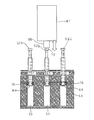
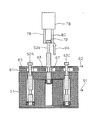
図12は、把持ヘッド78を備えた印刷機の支持ピン設定時の初期状態を示し、把持ヘッド78は押込ヘッド87と同様にXY方向、例えば水平方向に移動可能であり、且つ、図示しない昇降機構によって昇降可能であり、このヘッド78の下部には、水平方向に移動する一対の把持爪79、80が設けられている。また、各支持ピン52a、52b及び52cの延在部71は上述した実施形態の支持ピンより僅かに長く、延在部71の上部及び上端部72はシート85から上方へ突出している。
FIG. 12 shows an initial state when setting a support pin of a printing press equipped with a gripping
図12に示したように、下降した状態であり、プリント基板の支持に使用する支持ピン52bの上方に位置した把持ヘッド78の把持爪79、80が矢印95に示したように接近する水平方向に移動する。そして、把持爪79、80の下端により支持ピン52bの上端部72を係止した後、把持ヘッド78は図14に矢印96に示したように所定の高さ位置まで上昇し、支持ピン52bを引き上げる。この結果、支持ピン52bの中央部67は昇降部83に位置している。同様に、プリント基板の支持に使用するその他の支持ピンについても把持ヘッドが引き上げる。
As shown in FIG. 12, the
次に、図9に示した状態と同様に、矢印91及び92に示した方向へ支持ブロック51及びシート85は移動し、以後、上述した実施の形態の図9から図10に示した設定時の動作と同様に使用する支持ピンが位置決めされ、設定される。
Next, similarly to the state shown in FIG. 9, the
このように、把持ヘッド78を用いた場合には、使用する支持ピンを設定する動作を一層簡略化することができる。
As described above, when the gripping
以上のように本発明の実施態様について説明したが、上述の説明に基づいて当業者にとって種々の代替例、修正又は変形が可能であり、本発明はその趣旨を逸脱しない範囲で前述の種々の代替例、修正又は変形を包含するものである。 Although the embodiments of the present invention have been described above, various alternatives, modifications, and variations can be made by those skilled in the art based on the above description, and the present invention is not limited to the various embodiments described above without departing from the spirit of the present invention. It encompasses alternatives, modifications or variations.
1 スクリーン印刷機
24 基板支持装置
51 支持ブロック
52a〜b 支持ピン
53 支持孔
60a〜b 電磁弁(昇降手段)
65 括れ部
81 支持ベース
85 シート
87 押込装置
DESCRIPTION OF
65
Claims (12)
前記支持ピンを支持する支持ブロックと、
前記支持ピンを昇降させる昇降手段と、
前記支持ピンに対して相対的に移動が可能であり、上昇した状態の前記支持ピンを下から支持するベースと、
上下方向に移動可能で、下降して所望の前記支持ピンを前記支持ブロック内に押し込む押込装置とを備えた
ことを特徴とする基板支持装置。 In a substrate support device comprising a plurality of support pins for supporting a printed circuit board,
A support block for supporting the support pins;
Elevating means for elevating and lowering the support pins;
A base that is movable relative to the support pin and supports the support pin in a raised state from below;
A substrate support apparatus, comprising: a pushing device that is movable in a vertical direction and descends to push a desired support pin into the support block.
前記支持ピンを支持する複数の支持孔が間隔を存して上下方向に形成された支持ブロックと、
前記支持ピンを複数本同時に昇降させる昇降手段と、
支持ブロックの上に設けられ、前記支持ピンに対して移動が可能であり、上昇した状態の前記支持ピンを下から支持するベースと、
水平方向及び上下方向に移動可能で、下降して所望の前記支持ピンを前記支持孔内に押し込む押込装置とを備えた
ことを特徴とする基板支持装置。 In a substrate support device comprising a plurality of support pins for supporting a printed circuit board,
A support block in which a plurality of support holes for supporting the support pins are formed in the vertical direction with a space therebetween;
Elevating means for simultaneously elevating a plurality of the support pins;
A base provided on a support block, movable with respect to the support pin, and supporting the support pin in a raised state from below;
A substrate support device comprising: a pushing device that is movable in a horizontal direction and a vertical direction, and that descends to push a desired support pin into the support hole.
前記支持ピンを支持する複数の支持孔が間隔を存して上下方向に形成された支持ブロックと、
前記支持ピンを複数本同時に昇降させる昇降手段と、
支持ブロックの上に設けられ、前記支持ブックに対して水平方向に相対的に移動可能で前記支持ピンに対して接近し、上昇した状態の前記支持ピンの支持部を下から同時に支持するベースと、
水平方向及び上下方向に移動可能で、下降して所望の前記支持ピンを前記支持孔内に押し込む押込装置とを備えた
ことを特徴とする基板支持装置。 In a substrate support device comprising a plurality of support pins for supporting a printed circuit board,
A support block in which a plurality of support holes for supporting the support pins are formed in the vertical direction with a space therebetween;
Elevating means for simultaneously elevating a plurality of the support pins;
A base provided on a support block, capable of moving relative to the support book in a horizontal direction, approaching the support pin, and supporting a support portion of the support pin in a raised state simultaneously from below; ,
A substrate support device comprising: a pushing device that is movable in a horizontal direction and a vertical direction, and that descends to push a desired support pin into the support hole.
水平方向にスライド自在に設けられ、前記支持ピンを支持する複数の支持孔が間隔を存して上下方向に形成され、前記支持孔は前記支持ブロックの上部に形成されて前記支持ピンを上下にスライド自在に支持する上部孔とこの上部孔の下に形成され前記上部孔より断面積が大きい下部孔とから成り、この下部孔の上部と下部とにエア供給路が連通した支持ブロックと、
下部に設けられ前記下部孔内にて上下にスライドするスライド部と、このスライド部の上に形成されスライド部より断面積が小さく前記下部孔の側壁との間に空間が形成されると共に上昇により前記上部孔内に摺動して収まる下中間部とこの下中間部の上に形成され、断面積が前記下中間部より小さい中央部と、この中央部の上に形成され前記下中間部と断面形状が等しい上中間部と、この上中間部の上に形成され前記上中間部より断面積が小さく括れた延在部とを備えた支持ピンと、
支持ブロックの上に設けられ、前記支持ピンに対応して形成され前記上中間部に対応した昇降部とこの昇降部から連続して形成され前記支持ピンが上昇した状態で前記上中間部の下端を支持する支持部と備えた複数の貫通孔が形成されたベースと、
水平方向及び上下方向に移動可能で、下降して前記支持ピンを前記支持孔内に押し込む押込ヘッドとを備えた
ことを特徴とする基板支持装置。 In a substrate support device comprising a plurality of support pins for supporting a printed circuit board,
A plurality of support holes that are slidable in the horizontal direction are formed in the vertical direction with a space therebetween, and the support holes are formed in the upper part of the support block so that the support pins are moved up and down. A support block formed by an upper hole that is slidably supported and a lower hole that is formed below the upper hole and has a larger cross-sectional area than the upper hole, and an air supply path communicates with the upper and lower portions of the lower hole;
A space is formed between the slide part provided at the lower part and slides up and down in the lower hole and the side wall of the lower hole formed on the slide part and having a smaller cross-sectional area than the slide part and rising. A lower intermediate portion that slides and fits in the upper hole, and is formed on the lower intermediate portion, a central portion having a cross-sectional area smaller than the lower intermediate portion, and a lower intermediate portion formed on the central portion, A support pin comprising an upper intermediate portion having the same cross-sectional shape, and an extending portion formed on the upper intermediate portion and having a smaller cross-sectional area than the upper intermediate portion;
A lower part of the upper intermediate part provided on a support block, formed in correspondence with the support pin and corresponding to the upper intermediate part, and a lower part of the upper intermediate part formed continuously from the elevator part. A base formed with a plurality of through-holes and a support part for supporting
A substrate support apparatus comprising: a pushing head that is movable in a horizontal direction and a vertical direction, and that descends and pushes the support pin into the support hole.
前記支持ピンを支持する支持ブロックと、
前記支持ピンを昇降させる昇降手段と、
前記支持ピンに対して相対的に移動が可能であり、上昇した状態の前記支持ピンを下から支持するベースと、
上下方向に移動可能で、下降して所望の前記支持ピンを前記支持孔内に押し込む押込装置とを備えた基板支持装置を有した
ことを特徴とするスクリーン印刷機。 A screen printing machine comprising a plurality of support pins for supporting a printed circuit board, a screen in which pattern holes are formed, and a squeegee for applying the coating agent on the screen onto the printed circuit board through the pattern holes by moving. In
A support block for supporting the support pins;
Elevating means for elevating and lowering the support pins;
A base that is movable relative to the support pin and supports the support pin in a raised state from below;
A screen printing machine comprising a substrate support device that is movable in a vertical direction and includes a pushing device that descends and pushes a desired support pin into the support hole.
前記支持ピンを支持する複数の支持孔が間隔を存して上下方向に形成された支持ブロックと、
前記支持ピンを複数本同時に昇降させる昇降手段と、
支持ブロックの上に設けられ、前記支持ピンに対して移動が可能であり、上昇した状態の前記支持ピンを下から支持するベースと、
水平方向及び上下方向に移動可能で、下降して所望の前記支持ピンを前記支持孔内に押し込む押込装置とを備えた基板支持装置を有した
ことを特徴とするスクリーン印刷機。 A screen printing machine comprising a plurality of support pins for supporting a printed circuit board, a screen in which pattern holes are formed, and a squeegee for applying the coating agent on the screen onto the printed circuit board through the pattern holes by moving. In
A support block in which a plurality of support holes for supporting the support pins are formed in the vertical direction with a space therebetween;
Elevating means for simultaneously elevating a plurality of the support pins;
A base provided on a support block, movable with respect to the support pin, and supporting the support pin in a raised state from below;
A screen printing machine comprising a substrate support device that is movable in a horizontal direction and a vertical direction, and has a pushing device that descends and pushes a desired support pin into the support hole.
前記支持ピンを支持する複数の支持孔が間隔を存して上下方向に形成された支持ブロックと、
前記支持ピンを複数本同時に昇降させる昇降手段と、
支持ブロックの上に設けられ、前記支持ブックに対して水平方向に相対的に移動可能で前記支持ピンに対して接近し、上昇した状態の前記支持ピンの支持部を下から同時に支持するベースと、
水平方向及び上下方向に移動可能で、下降して所望の前記支持ピンを前記支持孔内に押し込む押込装置とを備えた基板支持装置を有した
ことを特徴とするスクリーン印刷機。 A screen printing machine comprising a plurality of support pins for supporting a printed circuit board, a screen in which pattern holes are formed, and a squeegee for applying the coating agent on the screen onto the printed circuit board through the pattern holes by moving. In
A support block in which a plurality of support holes for supporting the support pins are formed in the vertical direction with a space therebetween;
Elevating means for simultaneously elevating a plurality of the support pins;
A base provided on a support block, capable of moving relative to the support book in a horizontal direction, approaching the support pin, and supporting a support portion of the support pin in a raised state simultaneously from below; ,
A screen printing machine comprising a substrate support device that is movable in a horizontal direction and a vertical direction, and has a pushing device that descends and pushes a desired support pin into the support hole.
水平方向にスライド自在に設けられ、前記支持ピンを支持する複数の支持孔が間隔を存して上下方向に形成され、前記支持孔は前記支持ブロックの上部に形成されて前記支持ピンを上下にスライド自在に支持する上部孔とこの上部孔の下に形成され前記上部孔より断面積が大きい下部孔とから成り、この下部孔の上部と下部とにエア供給路が連通した支持ブロックと、
下部に設けられ前記下部孔内にて上下にスライドするスライド部と、このスライド部の上に形成されスライド部より断面積が小さく前記下部孔の側壁との間に空間が形成されると共に上昇により前記上部孔内に摺動して収まる下中間部とこの下中間部の上に形成され、断面積が前記下中間部より小さい中央部と、この中央部の上に形成され前記下中間部と断面形状が等しい上中間部と、この上中間部の上に形成され前記上中間部より断面積が小さく括れた延在部とを備えた支持ピンと、
支持ブロックの上に設けられ、前記支持ピンに対応して形成され前記上中間部に対応した昇降部とこの昇降部から連続して形成され前記支持ピンが上昇した状態で前記上中間部の下端を支持する支持部と備えた複数の貫通孔が形成されたベースと、
水平方向及び上下方向に移動可能で、下降して前記支持ピンを前記支持孔内に押し込む押込ヘッドとを備えた基板支持装置を有した
ことを特徴とするスクリーン印刷機 A screen printing machine comprising a plurality of support pins for supporting a printed circuit board, a screen in which pattern holes are formed, and a squeegee for applying the coating agent on the screen onto the printed circuit board through the pattern holes by moving. In
A plurality of support holes that are slidable in the horizontal direction are formed in the vertical direction with a space therebetween, and the support holes are formed in the upper part of the support block so that the support pins are moved up and down. A support block formed by an upper hole that is slidably supported and a lower hole that is formed below the upper hole and has a larger cross-sectional area than the upper hole, and an air supply path communicates with the upper and lower portions of the lower hole;
A space is formed between the slide part provided at the lower part and slides up and down in the lower hole and the side wall of the lower hole formed on the slide part and having a smaller cross-sectional area than the slide part and rising. A lower intermediate portion that slides and fits in the upper hole, and is formed on the lower intermediate portion, a central portion having a cross-sectional area smaller than the lower intermediate portion, and a lower intermediate portion formed on the central portion, A support pin comprising an upper intermediate portion having the same cross-sectional shape, and an extending portion formed on the upper intermediate portion and having a smaller cross-sectional area than the upper intermediate portion;
A lower part of the upper intermediate part provided on a support block, formed in correspondence with the support pin and corresponding to the upper intermediate part, and a lower part of the upper intermediate part formed continuously from the elevator part A base formed with a plurality of through-holes and a support part for supporting
A screen printing machine comprising a substrate support device that is movable in a horizontal direction and a vertical direction, and has a pressing head that descends and pushes the support pins into the support holes.
Priority Applications (3)
| Application Number | Priority Date | Filing Date | Title |
|---|---|---|---|
| JP2008323008A JP2010143085A (en) | 2008-12-18 | 2008-12-18 | Substrate supporting apparatus and screen printing machine |
| EP09015569A EP2213454A3 (en) | 2008-12-18 | 2009-12-16 | Substrate supporting device and screen printer |
| CN2009102624507A CN101746112B (en) | 2008-12-18 | 2009-12-18 | Substrate supporting device and screen printer |
Applications Claiming Priority (1)
| Application Number | Priority Date | Filing Date | Title |
|---|---|---|---|
| JP2008323008A JP2010143085A (en) | 2008-12-18 | 2008-12-18 | Substrate supporting apparatus and screen printing machine |
Publications (1)
| Publication Number | Publication Date |
|---|---|
| JP2010143085A true JP2010143085A (en) | 2010-07-01 |
Family
ID=42238634
Family Applications (1)
| Application Number | Title | Priority Date | Filing Date |
|---|---|---|---|
| JP2008323008A Pending JP2010143085A (en) | 2008-12-18 | 2008-12-18 | Substrate supporting apparatus and screen printing machine |
Country Status (3)
| Country | Link |
|---|---|
| EP (1) | EP2213454A3 (en) |
| JP (1) | JP2010143085A (en) |
| CN (1) | CN101746112B (en) |
Cited By (4)
| Publication number | Priority date | Publication date | Assignee | Title |
|---|---|---|---|---|
| JP2012074637A (en) * | 2010-09-29 | 2012-04-12 | Hitachi High-Tech Instruments Co Ltd | Set-up change method for support pin |
| JP2014099446A (en) * | 2012-11-13 | 2014-05-29 | Yamaha Motor Co Ltd | Substrate processing apparatus and buck-up pin inspection method |
| WO2016195943A1 (en) * | 2015-05-29 | 2016-12-08 | Applied Materials, Inc. | Grounding of conductive mask for deposition processes |
| WO2017187513A1 (en) * | 2016-04-26 | 2017-11-02 | ヤマハ発動機株式会社 | Substrate support device, screen printing device, coating device, surface mounting machine, and backup pin arrangement method |
Families Citing this family (2)
| Publication number | Priority date | Publication date | Assignee | Title |
|---|---|---|---|---|
| CN103140054A (en) * | 2011-12-01 | 2013-06-05 | 上海广联电子有限公司 | Base plate support device |
| CN114905842B (en) * | 2022-03-11 | 2025-08-19 | 伟创力电子技术(苏州)有限公司 | Automatic supporting mechanism for DEK printing machine |
Citations (5)
| Publication number | Priority date | Publication date | Assignee | Title |
|---|---|---|---|---|
| JPH0722794A (en) * | 1993-06-30 | 1995-01-24 | Taiho Seiki Co Ltd | Supporting apparatus for sheetlike member |
| JPH0722793A (en) * | 1993-06-30 | 1995-01-24 | Matsushita Electric Ind Co Ltd | Substrate holding device |
| JP2002335098A (en) * | 2001-05-10 | 2002-11-22 | Matsushita Electric Ind Co Ltd | Substrate lower receiving device, lower receiving pin module and substrate lowering method in electronic component mounting apparatus |
| JP2008153457A (en) * | 2006-12-18 | 2008-07-03 | Yamaha Motor Co Ltd | Backup pin setting jig, substrate support device, surface mounter, cream solder printing device, substrate inspection device, and backup pin setting method |
| JP2008235700A (en) * | 2007-03-22 | 2008-10-02 | Koganei Corp | Workpiece support |
Family Cites Families (6)
| Publication number | Priority date | Publication date | Assignee | Title |
|---|---|---|---|---|
| JPH05335800A (en) | 1992-05-30 | 1993-12-17 | Sony Corp | Setting equipment for under-supporting pin of printed board |
| US6202999B1 (en) * | 1997-02-14 | 2001-03-20 | Dek Printing Machines Ltd. | Workpiece support device |
| US6029966A (en) * | 1998-10-13 | 2000-02-29 | Hertz; Allen D. | Flexible, self conforming, workpiece support system |
| JP4322340B2 (en) | 1999-01-21 | 2009-08-26 | 株式会社日立ハイテクインスツルメンツ | Screen printing machine |
| JP4573692B2 (en) * | 2005-04-13 | 2010-11-04 | ヤマハ発動機株式会社 | Substrate support apparatus and substrate support method |
| JP4793987B2 (en) * | 2006-03-15 | 2011-10-12 | 富士機械製造株式会社 | Screen printing method and screen printing apparatus |
-
2008
- 2008-12-18 JP JP2008323008A patent/JP2010143085A/en active Pending
-
2009
- 2009-12-16 EP EP09015569A patent/EP2213454A3/en not_active Withdrawn
- 2009-12-18 CN CN2009102624507A patent/CN101746112B/en not_active Expired - Fee Related
Patent Citations (5)
| Publication number | Priority date | Publication date | Assignee | Title |
|---|---|---|---|---|
| JPH0722794A (en) * | 1993-06-30 | 1995-01-24 | Taiho Seiki Co Ltd | Supporting apparatus for sheetlike member |
| JPH0722793A (en) * | 1993-06-30 | 1995-01-24 | Matsushita Electric Ind Co Ltd | Substrate holding device |
| JP2002335098A (en) * | 2001-05-10 | 2002-11-22 | Matsushita Electric Ind Co Ltd | Substrate lower receiving device, lower receiving pin module and substrate lowering method in electronic component mounting apparatus |
| JP2008153457A (en) * | 2006-12-18 | 2008-07-03 | Yamaha Motor Co Ltd | Backup pin setting jig, substrate support device, surface mounter, cream solder printing device, substrate inspection device, and backup pin setting method |
| JP2008235700A (en) * | 2007-03-22 | 2008-10-02 | Koganei Corp | Workpiece support |
Cited By (5)
| Publication number | Priority date | Publication date | Assignee | Title |
|---|---|---|---|---|
| JP2012074637A (en) * | 2010-09-29 | 2012-04-12 | Hitachi High-Tech Instruments Co Ltd | Set-up change method for support pin |
| JP2014099446A (en) * | 2012-11-13 | 2014-05-29 | Yamaha Motor Co Ltd | Substrate processing apparatus and buck-up pin inspection method |
| WO2016195943A1 (en) * | 2015-05-29 | 2016-12-08 | Applied Materials, Inc. | Grounding of conductive mask for deposition processes |
| WO2017187513A1 (en) * | 2016-04-26 | 2017-11-02 | ヤマハ発動機株式会社 | Substrate support device, screen printing device, coating device, surface mounting machine, and backup pin arrangement method |
| JPWO2017187513A1 (en) * | 2016-04-26 | 2019-03-07 | ヤマハ発動機株式会社 | Substrate support device, screen printing device, coating device, surface mounter, and backup pin setup method |
Also Published As
| Publication number | Publication date |
|---|---|
| EP2213454A2 (en) | 2010-08-04 |
| EP2213454A3 (en) | 2012-01-18 |
| CN101746112A (en) | 2010-06-23 |
| CN101746112B (en) | 2012-06-27 |
Similar Documents
| Publication | Publication Date | Title |
|---|---|---|
| US11007768B2 (en) | Board work device having support member conveyance section for conveying board support member | |
| JP6898248B2 (en) | Lift tool assembly for stencil printers | |
| JP2010143085A (en) | Substrate supporting apparatus and screen printing machine | |
| CN105882121A (en) | Full-automatic silk screen processing platform and silk screen technology thereof | |
| KR20090064306A (en) | Screen printing machine | |
| EP3274173B1 (en) | Stencil printer having stencil shuttle assembly | |
| JP5305507B2 (en) | Substrate positioning device and substrate positioning method for screen printing machine | |
| JP2011189670A (en) | Screen printing machine and mask installation method in screen printing machine | |
| JP2010082919A (en) | Screen printing machine and screen printing method | |
| JP2002057498A (en) | Wiring board work system | |
| KR20110126581A (en) | How to Clean Your Screen Printing Machine and Screen Printing Machine | |
| KR20120110784A (en) | A window glass printing device | |
| KR20080022019A (en) | Fully automatic screen printing machine | |
| JPWO2017187513A1 (en) | Substrate support device, screen printing device, coating device, surface mounter, and backup pin setup method | |
| KR101628082B1 (en) | Silk-screen printing device | |
| JP2011073350A (en) | Substrate support device and screen printer | |
| KR20110096885A (en) | Board Mount Module Replacement Device for Screen Printers | |
| JP2018069467A (en) | Screen printer | |
| JP5517784B2 (en) | Support pin arrangement data creation device | |
| JP2012074637A (en) | Set-up change method for support pin | |
| JP4567510B2 (en) | Printing apparatus and stencil positioning method | |
| JP2010188645A (en) | Device for supporting substrate, device for mounting electronic component, method for supporting substrate, working method using device for mounting electronic component | |
| TWI783104B (en) | A stencil printer for printing viscous material on a substrate, a conveyor system, and a method for supporting and clamping a substrate of the same | |
| JP5198143B2 (en) | Electronic component mounting equipment | |
| JP2026063501A (en) | Transport jig, substrate handling device, and substrate support member |
Legal Events
| Date | Code | Title | Description |
|---|---|---|---|
| A621 | Written request for application examination |
Free format text: JAPANESE INTERMEDIATE CODE: A621 Effective date: 20110131 |
|
| A977 | Report on retrieval |
Free format text: JAPANESE INTERMEDIATE CODE: A971007 Effective date: 20120823 |
|
| A131 | Notification of reasons for refusal |
Free format text: JAPANESE INTERMEDIATE CODE: A131 Effective date: 20120829 |
|
| A521 | Written amendment |
Free format text: JAPANESE INTERMEDIATE CODE: A523 Effective date: 20121025 |
|
| A02 | Decision of refusal |
Free format text: JAPANESE INTERMEDIATE CODE: A02 Effective date: 20130507 |