JP4760887B2 - Door lock device - Google Patents
Door lock device Download PDFInfo
- Publication number
- JP4760887B2 JP4760887B2 JP2008250936A JP2008250936A JP4760887B2 JP 4760887 B2 JP4760887 B2 JP 4760887B2 JP 2008250936 A JP2008250936 A JP 2008250936A JP 2008250936 A JP2008250936 A JP 2008250936A JP 4760887 B2 JP4760887 B2 JP 4760887B2
- Authority
- JP
- Japan
- Prior art keywords
- lever
- lock
- locking lever
- locking
- double lock
- Prior art date
- Legal status (The legal status is an assumption and is not a legal conclusion. Google has not performed a legal analysis and makes no representation as to the accuracy of the status listed.)
- Expired - Fee Related
Links
- 230000007935 neutral effect Effects 0.000 claims description 31
- 238000006073 displacement reaction Methods 0.000 claims description 16
- 230000002093 peripheral effect Effects 0.000 claims description 13
- 230000001105 regulatory effect Effects 0.000 claims description 3
- 239000002184 metal Substances 0.000 description 5
- 230000007704 transition Effects 0.000 description 4
- 239000000463 material Substances 0.000 description 3
- 239000011347 resin Substances 0.000 description 3
- 229920005989 resin Polymers 0.000 description 3
- 238000005452 bending Methods 0.000 description 2
- 230000005540 biological transmission Effects 0.000 description 2
- 230000000694 effects Effects 0.000 description 1
- 238000011144 upstream manufacturing Methods 0.000 description 1
Images


Classifications
-
- E—FIXED CONSTRUCTIONS
- E05—LOCKS; KEYS; WINDOW OR DOOR FITTINGS; SAFES
- E05B—LOCKS; ACCESSORIES THEREFOR; HANDCUFFS
- E05B77/00—Vehicle locks characterised by special functions or purposes
- E05B77/22—Functions related to actuation of locks from the passenger compartment of the vehicle
- E05B77/24—Functions related to actuation of locks from the passenger compartment of the vehicle preventing use of an inner door handle, sill button, lock knob or the like
- E05B77/28—Functions related to actuation of locks from the passenger compartment of the vehicle preventing use of an inner door handle, sill button, lock knob or the like for anti-theft purposes, e.g. double-locking or super-locking
-
- E—FIXED CONSTRUCTIONS
- E05—LOCKS; KEYS; WINDOW OR DOOR FITTINGS; SAFES
- E05B—LOCKS; ACCESSORIES THEREFOR; HANDCUFFS
- E05B81/00—Power-actuated vehicle locks
- E05B81/12—Power-actuated vehicle locks characterised by the function or purpose of the powered actuators
- E05B81/16—Power-actuated vehicle locks characterised by the function or purpose of the powered actuators operating on locking elements for locking or unlocking action
-
- E—FIXED CONSTRUCTIONS
- E05—LOCKS; KEYS; WINDOW OR DOOR FITTINGS; SAFES
- E05B—LOCKS; ACCESSORIES THEREFOR; HANDCUFFS
- E05B81/00—Power-actuated vehicle locks
- E05B81/02—Power-actuated vehicle locks characterised by the type of actuators used
- E05B81/04—Electrical
- E05B81/06—Electrical using rotary motors
-
- E—FIXED CONSTRUCTIONS
- E05—LOCKS; KEYS; WINDOW OR DOOR FITTINGS; SAFES
- E05B—LOCKS; ACCESSORIES THEREFOR; HANDCUFFS
- E05B81/00—Power-actuated vehicle locks
- E05B81/24—Power-actuated vehicle locks characterised by constructional features of the actuator or the power transmission
- E05B81/32—Details of the actuator transmission
- E05B81/34—Details of the actuator transmission of geared transmissions
- E05B81/36—Geared sectors, e.g. fan-shaped gears
-
- Y—GENERAL TAGGING OF NEW TECHNOLOGICAL DEVELOPMENTS; GENERAL TAGGING OF CROSS-SECTIONAL TECHNOLOGIES SPANNING OVER SEVERAL SECTIONS OF THE IPC; TECHNICAL SUBJECTS COVERED BY FORMER USPC CROSS-REFERENCE ART COLLECTIONS [XRACs] AND DIGESTS
- Y10—TECHNICAL SUBJECTS COVERED BY FORMER USPC
- Y10S—TECHNICAL SUBJECTS COVERED BY FORMER USPC CROSS-REFERENCE ART COLLECTIONS [XRACs] AND DIGESTS
- Y10S292/00—Closure fasteners
- Y10S292/23—Vehicle door latches
-
- Y—GENERAL TAGGING OF NEW TECHNOLOGICAL DEVELOPMENTS; GENERAL TAGGING OF CROSS-SECTIONAL TECHNOLOGIES SPANNING OVER SEVERAL SECTIONS OF THE IPC; TECHNICAL SUBJECTS COVERED BY FORMER USPC CROSS-REFERENCE ART COLLECTIONS [XRACs] AND DIGESTS
- Y10—TECHNICAL SUBJECTS COVERED BY FORMER USPC
- Y10T—TECHNICAL SUBJECTS COVERED BY FORMER US CLASSIFICATION
- Y10T292/00—Closure fasteners
- Y10T292/08—Bolts
- Y10T292/1043—Swinging
- Y10T292/1044—Multiple head
- Y10T292/1045—Operating means
- Y10T292/1047—Closure
-
- Y—GENERAL TAGGING OF NEW TECHNOLOGICAL DEVELOPMENTS; GENERAL TAGGING OF CROSS-SECTIONAL TECHNOLOGIES SPANNING OVER SEVERAL SECTIONS OF THE IPC; TECHNICAL SUBJECTS COVERED BY FORMER USPC CROSS-REFERENCE ART COLLECTIONS [XRACs] AND DIGESTS
- Y10—TECHNICAL SUBJECTS COVERED BY FORMER USPC
- Y10T—TECHNICAL SUBJECTS COVERED BY FORMER US CLASSIFICATION
- Y10T292/00—Closure fasteners
- Y10T292/08—Bolts
- Y10T292/1043—Swinging
- Y10T292/1075—Operating means
- Y10T292/1082—Motor
-
- Y—GENERAL TAGGING OF NEW TECHNOLOGICAL DEVELOPMENTS; GENERAL TAGGING OF CROSS-SECTIONAL TECHNOLOGIES SPANNING OVER SEVERAL SECTIONS OF THE IPC; TECHNICAL SUBJECTS COVERED BY FORMER USPC CROSS-REFERENCE ART COLLECTIONS [XRACs] AND DIGESTS
- Y10—TECHNICAL SUBJECTS COVERED BY FORMER USPC
- Y10T—TECHNICAL SUBJECTS COVERED BY FORMER US CLASSIFICATION
- Y10T70/00—Locks
- Y10T70/50—Special application
- Y10T70/5093—For closures
- Y10T70/5155—Door
- Y10T70/5199—Swinging door
- Y10T70/5372—Locking latch bolts, biased
Landscapes
- Lock And Its Accessories (AREA)
Description
本発明は、ドアロック装置に関するものである。 The present invention relates to a door lock device.
従来、電気的な制御を行うことなく一つのモータで車両ドアのアンロック状態(解錠状態)、ロック状態(施錠状態)、室内側からの操作による車両ドアのロック状態からアンロック状態への移行を禁止するダブルロック状態(スーパーロック状態)の三つの状態に切り替え可能なドアロック装置として、例えば特許文献1に記載されたものが知られている。このドアロック装置では、モータ(33)の動力により回転部材(35)が中立位置から正転するとシルノブ駆動レバー(54)はロック側に変位してロック機構をロック状態に切替えるが作動レバー(56)は保持バネ(57)の弾力に抗して変位せず、モータはロック機構がロック状態に切替わるとオフとなって回転部材は中立復帰バネ(38)の弾力により中立位置に復帰するとともに作動レバーは保持バネの弾力により所定位置に復帰し、その後再度回転部材が正転すると作動レバーは保持バネの弾力に抗して変位して切替レバー(67)を変位させて空振機構を作動させる位置に係合ピン(53)を変位させる。一方、回転部材35には、逆転すると切替レバーと係合して係合ピンによる空振機構を解除させるスーパーロック解除段部(44)を形成している。
ところで、特許文献1では、シルノブ駆動レバーはアンロック側(アンロック位置)及びロック側(ロック位置)間を変位するのみであって、ダブルロック状態への切替えを作動レバーや切替レバー、中間レバー(64)、屈曲レバー(66)で構成されるリンク機構を利用して行っている。従って、ダブルロック状態に切替えるためのこれら専用部品を使用する分、ドアロック装置の構造が複雑になっている。 By the way, in Patent Document 1, the sill knob drive lever only displaces between the unlock side (unlock position) and the lock side (lock position), and the switching to the double lock state is performed by an operating lever, a switching lever, or an intermediate lever. (64), using a link mechanism composed of a bending lever (66). Accordingly, the structure of the door lock device is complicated by using these dedicated parts for switching to the double lock state.
本発明の目的は、より簡易な構造で、電気的な制御を行うことなく一つの電気的駆動源で車両ドアのアンロック状態、ロック状態、ダブルロック状態の三つの状態に切り替え可能なドアロック装置を提供することにある。 An object of the present invention is a door lock that has a simpler structure and can be switched to three states of an unlocked state, a locked state, and a double-locked state of a vehicle door with one electric drive source without performing electrical control. To provide an apparatus.
上記問題点を解決するために、請求項1に記載の発明は、車両ドアを車両ボデーに対して閉状態で保持するラッチ機構と、前記車両ドアに連係され、前記車両ドアが前記車両ボデーに対して開可能状態になるように前記ラッチ機構を動作させるための室内側の操作力及び室外側の操作力を前記ラッチ機構に伝達可能なアンロック位置と、前記車両ドアが前記車両ボデーに対して開可能状態になるように前記ラッチ機構を動作させるための室外側の操作力を前記ラッチ機構に伝達不能であるとともに前記アンロック位置へと変位するための室内側の操作力が加わった際に該アンロック位置へと変位するロック位置と、前記車両ドアが前記車両ボデーに対して開可能状態になるように前記ラッチ機構を動作させるための室外側の操作力を前記ラッチ機構に伝達不能であるとともに前記アンロック位置又は前記ロック位置へと変位するための室内側の操作力が加わっても該アンロック位置又は該ロック位置へと変位しないダブルロック位置とに切り替え自在なロッキングレバーと、前記ロッキングレバーに連結され、前記ロッキングレバーの前記アンロック位置及び前記ロック位置にそれぞれ対応して第1位置及び第2位置に変位するダブルロックレバーと、電気的駆動源と、前記ロッキングレバーと係合可能な第1係合部及び前記ダブルロックレバーと係合可能な第2係合部を有して前記車両ドアに連係され、前記電気的駆動源により所定中立位置から一側方向及び他側方向に移動駆動される駆動部材と、前記電気的駆動源の駆動停止に伴い前記駆動部材を前記所定中立位置に復帰させる復帰付勢手段とを備え、前記駆動部材は、前記ロッキングレバーが前記アンロック位置にあるとき、前記所定中立位置から一側方向への移動に伴い、前記ダブルロックレバーの前記第2位置への変位を規制しつつ前記第1係合部にて前記ロッキングレバーを押圧して前記ロック位置に変位させ、続く前記所定中立位置への復帰に伴い、前記ダブルロックレバーを解放して前記第2位置への変位を許容するとともに前記第1係合部による前記ロッキングレバーとの係合を解放し、前記所定中立位置から一側方向への再移動に伴い、前記第2係合部にて前記第2位置にある前記ダブルロックレバーを押圧して該ダブルロックレバーの連結される前記ロッキングレバーを前記ダブルロック位置に変位させることを要旨とする。 In order to solve the above problem, the invention according to claim 1 is related to a latch mechanism that holds a vehicle door in a closed state with respect to the vehicle body, and the vehicle door is connected to the vehicle body. An unlock position where the operating force on the indoor side and the operating force on the outdoor side for operating the latch mechanism to be in an openable state can be transmitted to the latch mechanism, and the vehicle door is against the vehicle body. When the outdoor operation force for operating the latch mechanism so as to be opened is not transmitted to the latch mechanism and the indoor operation force for displacing to the unlock position is applied A locking position for shifting to the unlocking position, and an outdoor operating force for operating the latch mechanism so that the vehicle door can be opened with respect to the vehicle body. The mechanism cannot be transmitted and can be switched to the unlocked position or the double-locked position that does not move to the locked position even when an indoor operation force is applied to move to the unlocked position or the locked position. A locking lever, a double lock lever connected to the locking lever and displaced to a first position and a second position corresponding to the unlock position and the lock position of the locking lever, an electric drive source, A first engagement portion engageable with the locking lever and a second engagement portion engageable with the double lock lever are linked to the vehicle door, and one side from a predetermined neutral position by the electric drive source A drive member that is driven to move in the direction and the other direction, and the drive member is returned to the predetermined neutral position when the drive of the electric drive source is stopped. Return biasing means, and when the locking lever is in the unlocked position, the drive member moves the double lock lever to the second position as it moves from the predetermined neutral position to one side. While the displacement is restricted, the first engaging portion presses the locking lever to displace it to the lock position, and with the subsequent return to the predetermined neutral position, the double lock lever is released to release the second position. And the engagement with the locking lever by the first engagement portion is released, and the second engagement portion causes the second engagement portion to move in the first direction along with the re-movement in the one side direction. The gist is to press the double lock lever at the second position to displace the locking lever connected to the double lock lever to the double lock position.
請求項2に記載の発明は、請求項1に記載のドアロック装置において、前記車両ドアに固定されたベース部材と、前記ベース部材に形成されたストッパ部とを備え、前記駆動部材は、前記ロッキングレバーが前記アンロック位置にあるとき、前記所定中立位置から一側方向への移動に伴い、前記ダブルロックレバーの前記第2位置への変位を規制しつつ前記第1係合部にて前記ロッキングレバーを押圧して該ロッキングレバーを前記ダブルロックレバーが前記ストッパ部に係合する前記ロック位置に変位させ、続く前記所定中立位置への復帰に伴い、前記ダブルロックレバーを解放して前記第2位置への変位を許容し、該ダブルロックレバーは、前記第2位置へ変位した際に該ダブルロックレバーと前記ストッパ部との係合が解除され、前記ロッキングレバーの前記ロック位置から前記ダブルロック位置への変位が許容されることを要旨とする。
The invention according to
請求項3に記載の発明は、請求項2に記載のドアロック装置において、前記ベース部材はガイド部を備え、該ガイド部は、前記ストッパ部と、前記ロッキングレバーが前記アンロック位置から前記ロック位置に変位する際に前記ダブルロックレバーを前記第1位置の状態で案内する第1ガイド部と、前記ロッキングレバーが前記ロック位置から前記ダブルロック位置に変位する際に前記ダブルロックレバーを前記第2位置の状態で案内する第2ガイド部とを有することを要旨とする。 According to a third aspect of the present invention, in the door lock device according to the second aspect, the base member includes a guide portion, and the guide portion includes the stopper portion, and the locking lever is locked from the unlock position. A first guide portion for guiding the double lock lever in the first position when displaced to a position, and the double lock lever when the locking lever is displaced from the lock position to the double lock position. The gist of the present invention is to have a second guide portion that guides in two positions.
上記各構成によれば、車両ドアのアンロック状態、ロック状態、ダブルロック状態への切替えは、電気的な制御を行うことなく一つの電気的駆動源で一側方向及び他側方向に移動駆動される前記駆動部材と前記ロッキングレバー及び前記ダブルロックレバーとの係合態様が、これらロッキングレバー及びダブルロックレバーの変位に応じて変更されることで行われる。従って、これらアンロック状態、ロック状態、ダブルロック状態への切替えを、前記アンロック位置、前記ロック位置及び前記ダブルロック位置の三位置を変位する前記ロッキングレバーと、該ロッキングレバーに連動する前記ダブルロックレバーとからなる極めて簡易な構造で行うことができる。そして、前記切替えに係る部品点数を削減することができる。 According to each of the above-described configurations, the vehicle door is switched to the unlocked state, the locked state, and the double-locked state by moving and driving in one side direction and the other side direction with one electric drive source without performing electrical control. The engagement mode of the drive member, the locking lever, and the double lock lever is changed according to the displacement of the locking lever and the double lock lever. Therefore, switching to the unlocked state, the locked state, and the double locked state is performed by moving the locking lever that displaces the unlocked position, the locked position, and the double locked position, and the double lever that is interlocked with the locking lever. It can be performed with a very simple structure comprising a lock lever. In addition, the number of parts related to the switching can be reduced.
請求項4に記載の発明は、請求項2又は3に記載のドアロック装置において、前記駆動部材及び前記ロッキングレバーは、互いに同軸で前記ベース部材に回動自在に連結されていることを要旨とする。 According to a fourth aspect of the present invention, in the door lock device according to the second or third aspect, the drive member and the locking lever are coaxially connected to each other and rotatably connected to the base member. To do.
同構成によれば、前記駆動部材及び前記ロッキングレバーの配置スペースを集約し全体としてコンパクトにまとめることができる。特に、前記ロッキングレバーは、前記アンロック位置、前記ロック位置及び前記ダブルロック位置への変位を一軸の回動によって実現しているため、装置全体としてより小型化することができる。 According to this configuration, the arrangement space of the driving member and the locking lever can be integrated and compacted as a whole. In particular, since the locking lever realizes displacement to the unlock position, the lock position, and the double lock position by uniaxial rotation, the entire apparatus can be further downsized.
請求項5に記載の発明は、請求項2〜4のいずれか一項に記載のドアロック装置において、前記ロッキングレバーに並設された二つの係止突部と、前記ベース部材に支持され、前記ロッキングレバーの前記アンロック位置、前記ロック位置及び前記ダブルロック位置にそれぞれ対応して互いに異なる個数で前記係止突部を弾性的に挟持する保持手段とを備えたことを要旨とする。
The invention according to claim 5 is the door lock device according to any one of
同構成によれば、前記保持手段にて前記ロッキングレバーに並設された二つの係止突部を選択的に挟持することで、前記ロッキングレバーを前記アンロック位置、前記ロック位置及び前記ダブルロック位置に安定的に保持することができる。特に、前記保持手段は、互いに異なる個数になるように前記係止突部を弾性的に挟持することで、前記ロッキングレバーを前記アンロック位置、前記ロック位置及び前記ダブルロック位置にそれぞれ保持することができるため、基本的に適宜の突部を選択的に挟持し得る汎用の保持手段(例えばスナップピンなど)を利用することができる。 According to this configuration, the locking lever is selectively held between the two locking projections arranged in parallel with the locking lever, so that the locking lever is moved to the unlock position, the lock position, and the double lock. It can be stably held in position. In particular, the holding means holds the locking lever in the unlocked position, the locked position, and the double-locked position by elastically holding the locking projections so as to have different numbers. Therefore, it is possible to use general-purpose holding means (for example, a snap pin) that can selectively hold an appropriate protrusion.
本発明では、より簡易な構造で、電気的な制御を行うことなく一つの電気的駆動源で車両ドアのアンロック状態、ロック状態、ダブルロック状態の三つの状態に切り替え可能なドアロック装置を提供することができる。 In the present invention, a door lock device having a simpler structure and capable of switching between three states of an unlocked state, a locked state, and a double locked state of a vehicle door with one electric drive source without performing electrical control. Can be provided.
以下、本発明を具体化した一実施形態を図面に従って説明する。
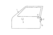
図1に示されるように、車両ドア1内には、車両ボデー(図示略)に設けられたストライカ2と係合して該車両ボデーに対して車両ドア1を閉状態で保持するドアロック装置10がその後縁に沿って配設されている。また、車両ドア1には、その室内側に露出する態様でインサイドハンドル3が設置されるとともに、その室外側に露出する態様でアウトサイドハンドル4が設置されている。なお、本実施形態のドアロック装置10は、室内側からのアンロック・ロック操作に係るロックノブの割愛された、いわゆるノブレスタイプとなっている。
DESCRIPTION OF EXEMPLARY EMBODIMENTS Hereinafter, an embodiment of the invention will be described with reference to the drawings.
As shown in FIG. 1, a door lock device that engages with a
図2に示されるように、ドアロック装置10が備えるラッチ機構11は、ラッチ12及びポール13を備えて構成されており、前記ストライカ2と係合することで車両ボデーに対して車両ドア1を閉状態で保持する。すなわち、車両ドア1を閉めるときラッチ12が回転してストライカ2と係合し、同時にポール13がラッチ12を回り止めすることで車両ドア1を閉状態で保持する。また、ポール13を動かしてラッチ12の回り止めを解除すると、該ラッチ12は復帰スプリング(図示略)に付勢されて戻り回転し、ストライカ2との係合状態を解除して車両ボデーに対して車両ドア1を開可能状態にする。
As shown in FIG. 2, the latch mechanism 11 included in the
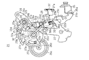
次に、ドアロック装置10について、図3〜図10に従って更に詳述する。なお、図3は、ドアロック装置10を示す側面図であり、図4は、図3のA−A線に沿った断面図である。また、図5は、図3の一部の部材を抽出して示す拡大図である。
Next, the
図3に示すように、ドアロック装置10は、車両ドアに固定されたベース部材としての箱状のハウジング21と、インサイドレバー22と、インサイドオープンレバー23と、ロッキングレバーとしてのアクティブレバー24と、ダブルロックレバー25と、電気的駆動源としての切替用アクチュエータ26と、駆動部材としてのセクタギヤ27と、パニックレバー28と、オープンリンク29と、キャンセルレバー30とを備えて構成される。
As shown in FIG. 3, the
図3及び図5に示すように、前記インサイドレバー22は、例えば金属板からなり、所定の初期回動位置に配置される態様で、回転軸O1を中心にハウジング21に対し図示時計回転方向及び反時計回転方向に回動可能に連結されている。このインサイドレバー22は、図示上側に延出する先端部が回転軸O1側に折り返されて鋏形状の係止片22aを形成する。インサイドレバー22は、係止片22aにおいて前記インサイドハンドル3と連係されており、該インサイドハンドル3の開方向への操作により、図示反時計回転方向に回動する。なお、インサイドレバー22は、回転軸O1を中心とする径方向一側(図5の右上側)に延出する鉤爪状の押圧片22bを有する。
As shown in FIGS. 3 and 5, the
前記インサイドオープンレバー23は、例えば金属板からなり、前記インサイドレバー22の紙面に直交する奥側で前記回転軸O1を中心にハウジング21に対し図示時計回転方向及び反時計回転方向に回動可能に連結されている。このインサイドオープンレバー23は、前記インサイドレバー22と一体回動するようにこれに連結されている。なお、インサイドオープンレバー23は、回転軸O1を中心とする径方向他側(図5の右下側)に延出する鉤爪状の押圧片23aを有する。この押圧片23aは、回転軸O1を中心とする周方向で、インサイドレバー22の押圧片22bから離隔配置されている。
The inside
前記アクティブレバー24は、例えば樹脂材にて成形されており、インサイドレバー22の図示上側で前記回転軸O1に平行な回転軸O2を中心にハウジング21に対し図示時計回転方向及び反時計回転方向に回動可能に連結されている。なお、アクティブレバー24の回動は、ハウジング21に規制される態様で所定の回動範囲内に制限されている。このアクティブレバー24には、回転軸O2を中心とする周方向に並設された二つの係止突部24a,24bが形成されている。これら係止突部24a,24bは、隣接する外周部同士が連続する態様で全体として略「8」の字形状を呈して、ハウジング21の底壁側となる紙面に直交する奥側に突設されている。一方、ハウジング21(底壁)には、アクティブレバー24の位置決め用の保持手段としての節度スプリング31が取着されている。この節度スプリング31は、コイル部から延出する一対の「く」の字形の端部31a,31b間が幅狭になる側の付勢力を発生する、いわゆるスナップピンからなるもので、前記係止突部24a,24bを弾性的に挟持することでアクティブレバー24の回動位置を保持する。
The
ここで、ハウジング21によりアクティブレバー24の図示反時計回転方向への回動が規制され、節度スプリング31が係止突部24a,24bのいずれも挟持しない図3、図5及び図10に示した回動位置をアクティブレバー24のアンロック位置という。また、アンロック位置から図示時計回転方向に所定角度だけ回動した回動位置であって、節度スプリング31が一方の係止突部24aのみを挟持する図6及び図7に示した回動位置をアクティブレバー24のロック位置という。さらに、ロック位置から図示時計回転方向に所定角度だけ回動した回動位置であって、ハウジング21によりアクティブレバー24の図示時計回転方向への回動が規制され、節度スプリング31が全ての係止突部24a,24bを挟持する図8及び図9に示した回動位置をアクティブレバー24のダブルロック位置という。つまり、節度スプリング31は、アクティブレバー24のアンロック位置、ロック位置及びダブルロック位置にそれぞれ対応して互いに異なる個数で係止突部24a,24bを弾性的に挟持している。
Here, the rotation of the
なお、アクティブレバー24は、回転軸O2を中心とする径方向一側(図3の上側)に延出する取付片24cを有するとともに、回転軸O2を中心とする径方向他側(図3の右下側)に前記キャンセルレバー30の近傍まで延出する当接片24dを有し、更にセクタギヤ25の図示左側で紙面に直交する手前側に突設された四角柱状の角ボス24eを有する。
The
前記ダブルロックレバー25は、例えば樹脂材にて成形されており、アクティブレバー24の取付片24cにおいて、前記回転軸O1,O2に平行な回転軸O3を中心に図示時計回転方向及び反時計回転方向に回動可能に連結されている。このダブルロックレバー25は、取付片24cの図示左側でハウジング21の底壁側となる紙面に直交する奥側に突設されたガイドピン25aを有する。一方、ハウジング21(底壁)には、ガイドピン25aの回転軸O2を中心とする内周側で該ガイドピン25aの当接可能なリブ状のガイド部32が形成されている。図5に示すように、このガイド部32は、回転軸O2を中心とする周方向に延在する円弧状の第1ガイド部32aを有するとともに、該第1ガイド部32aの外径よりも短い外径で回転軸O2を中心とする周方向に延在する円弧状の第2ガイド部32bを有する。なお、第2ガイド部32bは、第1ガイド部32aの図示時計回転方向に回動する側に隣接配置されており、これら第1及び第2ガイド部32a,32b間の径方向の段差は傾斜ガイド部32cによって滑らかに繋がっている。
The
また、ダブルロックレバー25は、その先端部25bにハウジング21の底壁側となる紙面に直交する奥側に突設されたブロック状のストッパ部25cを有する。このストッパ部25cは、ガイド部32(第1ガイド部32a)の回転軸O2を中心とする内周側に配置されている。一方、ガイド部32は、傾斜ガイド部32cの回転軸O2を中心とする内周側で、該回転軸O2を中心とする径方向に延びる段差32dを形成する。
In addition, the
そして、ダブルロックレバー25には、回転軸O3周りに巻回され一端がアクティブレバー24に係止された付勢手段としてのねじりコイルスプリング33の他端が係止されている(図3参照)。これにより、ダブルロックレバー25は、ガイドピン25aがガイド部32に当接する側(図示反時計回転方向に回動する側)に常時付勢されている。
The
ここで、アクティブレバー24がアンロック位置にあるとき、ダブルロックレバー25のガイドピン25aは、ガイド部32の第1ガイド部32aに当接している(図5参照)。このときの回動位置をダブルロックレバー25の第1位置という。一方、アクティブレバー24がロック位置〜ダブルロック位置にあるとき、ダブルロックレバー25のガイドピン25aは、ガイド部32の第2ガイド部32bに当接している(図7〜図9参照)。このときの回動位置をダブルロックレバー25の第2位置という。
Here, when the
ガイド部32に案内されるダブルロックレバー25は、第1位置にあるときに回転軸O2を中心とする周方向に円弧状に延在している。そして、前記段差32dは、前記ストッパ部25cの回転軸O2を中心とする回動軌跡上に配置されている。従って、アンロック位置にあるアクティブレバー24がロック位置へと変位すべく図示時計回転方向に回動すると、第1ガイド部32aに案内されつつアクティブレバー24に連動するダブルロックレバー25のストッパ部25cが段差32dに当接することで該ダブルロックレバー25とともにアクティブレバー24の回動が係止される(図6参照)。換言すれば、アクティブレバー24は、ストッパ部25c及び段差32dが当接することでロック位置で停止する。また、ダブルロックレバー25は、第1位置から第2位置への変位に伴い、第1及び第2ガイド部32a,32b間の径方向の段差分だけ図示反時計回転方向、即ち先端部25bが回転軸O2を中心とする径方向内側に変位する方向に回動する。そして、前記段差32dは、前記ストッパ部25cの回転軸O2を中心とする回動軌跡から外れる。
The
図3に示すように、前記切替用アクチュエータ26は、アクティブレバー24等の図示左側でハウジング21に設置された電動モータ26aを備えるとともに、該電動モータ26aの回転軸に固着されたウォーム26bを備え、更にセクタギヤ27及びアクティブレバー24の紙面に直交する奥側で回転軸O1〜O3と平行な回転軸O4を中心にハウジング21に対し回転可能に支持されて前記ウォーム26bと噛合するウォームホイール26cを備える。そして、このウォームホイール26cの中心部には、該ウォームホイール26cと一体回転する小径の出力ギヤ26dが紙面に直交する手前側に突出する態様で固定されている。従って、切替用アクチュエータ26は、電動モータ26aが回転駆動されることで、ウォーム26b及びウォームホイール26c(ウォームギヤ)を介して出力ギヤ26dを回転させる。
As shown in FIG. 3, the switching
前記セクタギヤ27は、例えば樹脂材にて成形されており、前記アクティブレバー24の紙面に直交する手前側で前記回転軸O2を中心にハウジング21に対し図示時計回転方向及び反時計回転方向に回動可能に連結されている。なお、セクタギヤ27の回動は、ハウジング21に係止されるアクティブレバー24又はダブルロックレバー25を介して所定の回動範囲内に制限されている。このセクタギヤ27は、切替用アクチュエータ26の出力ギヤ26d側に延出する扇形のギヤ部27aを有する。ギヤ部27aの軸方向の位置は、前記出力ギヤ26dの軸方向の位置と重合している。セクタギヤ27は、ギヤ部27aにおいて切替用アクチュエータ26の出力ギヤ26dに噛合連結されており、切替用アクチュエータ26によって回転駆動される。なお、前記ウォームホイール26cには、回転軸O4周りに巻回され一端がハウジング21に係止された復帰付勢手段としての復帰スプリング34の他端が係止されている。セクタギヤ27は、切替用アクチュエータ26の駆動停止(駆動力の解放)に伴い、その回動位置が所定中立位置に復帰するように復帰スプリング34によりウォームホイール26cを介して常時付勢されている。換言すれば、切替用アクチュエータ26は、復帰スプリング34の付勢力に抗してセクタギヤ27を回動駆動している。
The
また、セクタギヤ27は、ギヤ部27aの回転軸O2を中心とする内周側で該回転軸O2を中心とする周方向に延在して前記角ボス24eが紙面に直交する奥側から挿通される第1係合部としての円弧状の係合孔27bを有する。セクタギヤ27が前記所定中立位置にあり、且つ、アクティブレバー24がアンロック位置にあるとき、係合孔27bの一側の終端は前記角ボス24eに当接又は近接している(図5参照)。従って、この状態で、セクタギヤ27が図示時計回転方向に回動すると、係合孔27bの内壁面にて前記角ボス24eが押圧され、アクティブレバー24が一体で図示時計回転方向に回動する。そして、アクティブレバー24は、ストッパ部25c及び段差32dが当接することでロック位置で停止する(図6参照)。また、セクタギヤ27が前記所定中立位置にあり、且つ、アクティブレバー24がロック位置にあるとき、前記角ボス24eは係合孔27bの長手方向中央部に配置されている(図7参照)。そして、ストッパ部25cの回転軸O2を中心とする回動軌跡は、段差32dから外れている。従って、この状態で、セクタギヤ27が図示時計回転方向又は図示反時計回転方向に回動すると、前記角ボス24eは係合孔27b内を空走する。さらに、セクタギヤ27が前記所定中立位置にあり、且つ、アクティブレバー24がダブルロック位置にあるとき、係合孔27bの他側の終端は前記角ボス24eに当接又は近接している(図9参照)。従って、この状態で、セクタギヤ27が図示反時計回転方向に回動(逆回動)すると、係合孔27bの内壁面にて前記角ボス24eが押圧され、前記アンロック位置へと変位すべくアクティブレバー24が一体で図示反時計回転方向に回動する。そして、アクティブレバー24は、ハウジング21により図示反時計回転方向への回動が規制されることでアンロック位置で停止する(図10参照)。
The
また、セクタギヤ27は、回転軸O2を中心とするガイド部32の内周側でダブルロックレバー25の近傍まで延出する第2係合部としての槌形の押圧片27cを有する。押圧片27cの軸方向の位置は、前記ダブルロックレバー25の軸方向の位置と重合している。そして、前記ダブルロックレバー25が前記第1位置にあるとき、該ダブルロックレバー25(先端部25b)は押圧片27cの回動軌跡から外れるように設定されている(図5参照)。
Further, the
一方、アクティブレバー24を前記ロック位置へと変位させるべく前記セクタギヤ27を図示時計回転方向に回動させるとき、ダブルロックレバー25のガイドピン25aが第2ガイド部32bの回転軸O2を中心とする外周側に配置される(図6参照)。そして、コイルスプリング33に付勢されて前記第2位置へと変位しようとするダブルロックレバー25は、押圧片27cの外周面27dに当接することで当該変位が規制される。従って、アクティブレバー24は、ダブルロックレバー25及びセクタギヤ27の干渉によって阻害されることなく前記ロック位置へと変位する。
On the other hand, when the
そして、アクティブレバー24が前記ロック位置へと変位した後、切替用アクチュエータ26の駆動が停止されると、セクタギヤ27は、ウォームホイール26cを介して復帰スプリング34に付勢されて図示反時計回転方向に回動(戻り回動)し前記所定中立位置に復帰する(図7参照)。これに伴い、セクタギヤ27は、押圧片27cの外周面27dにおけるダブルロックレバー25の係止を解放して第2位置への変位を許容するとともに、前記角ボス24eを係合孔27bの長手方向中央部に配置して該係合孔27bによる前記角ボス24eとの係合を解放する。前記第2位置にあるとき、ダブルロックレバー25(先端部25b)は、押圧片27cの回動軌跡上に配置されるように設定されている。
When the drive of the switching
従って、この状態で、前記セクタギヤ27を図示時計回転方向に再び回動させると、押圧片27cにて前記第2位置にあるダブルロックレバー25が押圧されることで、該ダブルロックレバー25の連結されるアクティブレバー24が一体で図示時計回転方向に回動する。そして、アクティブレバー24は、ハウジング21により図示時計回転方向への回動が規制されることでダブルロック位置で停止する(図8参照)。このとき、アクティブレバー24は、前記角ボス24eが係合孔27b内を相対的に空走することで、これらの干渉によって前記ダブルロック位置への変位が阻害されることはない。
Accordingly, when the
そして、アクティブレバー24が前記ダブルロック位置へと変位した後、切替用アクチュエータ26の駆動が停止されると、セクタギヤ27は、ウォームホイール26cを介して復帰スプリング34に付勢されて図示反時計回転方向に回動(戻り回動)し前記所定中立位置に復帰する(図9参照)。このとき、係合孔27bの他側の終端は前記角ボス24eに当接又は近接している。
When the drive of the switching
一方、この状態で、セクタギヤ27を図示反時計回転方向に回動(逆回動)させると、係合孔27bの内壁面にて前記角ボス24eが押圧され、アクティブレバー24が一体で図示反時計回転方向に回動する。そして、アクティブレバー24は、ハウジング21により図示反時計回転方向への回動が規制されることでアンロック位置で停止する(図10参照)。同時に、前記第2位置にあるダブルロックレバー25は、ガイドピン25aが傾斜ガイド部32cを介して第2ガイド部32bから第1ガイド部32aへと案内されることで前記第1位置に変位する。その後、切替用アクチュエータ26の駆動が停止されると、セクタギヤ27は、ウォームホイール26cを介して復帰スプリング34に付勢されて図示時計回転方向に回動(戻り回動)し前記所定中立位置に復帰する(図5参照)。
On the other hand, in this state, when the
なお、前記切替用アクチュエータ26は、キーブレードやドア室内トリムに設けた切替用スイッチの遠隔操作が図示しない制御回路にて検出されることで一定時間だけ駆動制御されるものである。つまり、切替用アクチュエータ26は、電動モータ26aの回転方向に応じて供給電源の極性が変更されることを除けば特別に電気的な制御(位置制御など)がされているわけではなく、アクティブレバー24は、切替用アクチュエータ26の駆動期間中に前述の態様で機械的に係止されることでアンロック位置、ロック位置及びダブルロック位置に選択的に切り替わる。
The switching
前記パニックレバー28は、例えば金属板からなり、前記回転軸O2を中心にハウジング21に対し図示時計回転方向及び反時計回転方向に回動可能に連結されている。このパニックレバー28は、回転軸O2周りに巻回されて一端が前記アクティブレバー24に係止された付勢部材(図示略)の他端が係止されることで、基本的に前記アクティブレバー24と一体回動するように支持されている。なお、パニックレバー28の先端部には、紙面に直交する手前側に突出する係止ピン28aが取着されている。
The
前記オープンリンク29は、例えば金属板からなり、上下方向に延在するとともに、該オープンリンク29の一方の端部には、前記パニックレバー28の係止ピン28aが挿通される長孔状の係合溝29aが形成されている。オープンリンク29は、パニックレバー28に対し係合溝29aの長手方向に沿って移動可能に連結されている。
The
また、オープンリンク29の他方の端部には、ハウジング21に設けられたオープンレバー35に連結される連結部29bが形成されており、オープンリンク29はオープンレバー35に対し揺動可能に連結されている。このオープンレバー35は、支持ピン36にてハウジング21に回動可能に取り付けられており、トーションスプリング(図示略)により所定の回動位置に安定配置されている。オープンレバー35は、一方の端部35aにおいて前記オープンリンク29の連結部29bと連結されており、回動中心を挟んでその反対側の他方の端部において前記アウトサイドハンドル4と連係される。オープンレバー35は、アウトサイドハンドル4の開方向への操作により、トーションスプリングに抗して端部35a、すなわちオープンリンク29を上動させるように回動する。
The other end of the
さらに、オープンリンク29には、上記係合溝29a及び連結部29bの中間部にL字状の係合片部29cが形成されている。この係合片部29cは、ハウジング21に回動可能に取り付けられたリフトレバー37の近傍に配置されている。このリフトレバー37は、前記ポール13(図2参照)と一体回動するように連結されている。そして、リフトレバー37の前記係合片部29c側の先端部37aが上動するように該リフトレバー37が回動すると、前記ポール13の一体回動に伴い、ラッチ機構11によるストライカ2との係合状態が解除され、前記車両ドア1が車両ボデーに対して開可能状態となる。
Further, the
なお、前記係合片部29cは、前記インサイドオープンレバー23の押圧片23aに上下方向で対向配置され、該押圧片23aの回動軌跡上に配置されている。従って、例えばインサイドオープンレバー23を図示反時計回転方向に回動させると、前記押圧片23aによって係合片部29cの対向する端面が押圧されて、オープンリンク29が上動する。
The
ここで、アクティブレバー24のアンロック位置、ロック位置及びダブルロック位置に対応する係合片部29c及び先端部37aの配置関係について説明する。アクティブレバー24がアンロック位置にある状態(図3、図5参照)では、パニックレバー28の係止ピン28aによってオープンリンク29の一方の端部が一側(図3、図5の右側)に案内されている。このとき、上記係合片部29c及び先端部37aは、上下方向で対向配置されており、係合溝29aもその長手方向が上下方向に一致するように配置されている。従って、この状態でオープンリンク29(係合片部29c)を前述の態様で上動させれば、係合片部29cに押圧されて先端部37aが上動し、ラッチ機構11によるストライカ2との係合状態が解除される。
Here, the arrangement relationship between the
一方、アクティブレバー24がロック位置にある状態(図7参照)又はダブルロック位置にある状態(図9参照)では、パニックレバー28の係止ピン28aによってオープンリンク29の一方の端部が他側(図7、図9の左側)に案内されている。このとき、上記係合片部29cは、係合溝29aの長手方向に沿う延長線が先端部37aから外れるように配置されている。従って、オープンリンク29が上動しても、係合片部29cによって先端部37aが上動するように押圧されることはなく、ラッチ機構11によるストライカ2との係合状態は維持される。
On the other hand, when the
前記キャンセルレバー30は、例えば金属板からなり、前記インサイドレバー22及びアクティブレバー24間において、前記回転軸O1〜O4に平行な回転軸O5を中心にハウジング21に対し図示時計回転方向及び反時計回転方向に回動可能に連結されている。このキャンセルレバー30は、U字状に折り返す先端部の終端が前記押圧片22bの近傍で紙面に直交する手前側に屈曲してなる「く」の字形の当接片30aを形成するとともに、前記当接片24dに臨んで平坦に成形された係合片30bを形成する。
The cancel
キャンセルレバー30には、回転軸O5周りに巻回され一端がハウジング21に係止されたねじりコイルスプリング38の他端が係止されている(図3参照)。そして、キャンセルレバー30は、コイルスプリング38により、当接片30aが前記インサイドレバー22の押圧片22bに当接する側(図示反時計回転方向に回動する側)に常時付勢されている。従って、キャンセルレバー30は、通常は、所定の初期回動位置に配置されるインサイドレバー22に対応して所定回動位置に付勢保持されている。そして、インサイドハンドル3の開方向への操作によりインサイドレバー22が図示反時計回転方向に回動すると、キャンセルレバー30は、当接片30aが押圧片22bに押圧されることで図示時計回転方向に回動する。
The other end of the
ここで、アクティブレバー24がロック位置にある状態(図7参照)では、前記当接片24dは係合片30bの回動軌跡上に配置されている。従って、インサイドハンドル3の開方向への操作により前述の態様でキャンセルレバー30が図示時計回転方向に回動すると、係合片30bにて当接片24dが押圧されることでアクティブレバー24が図示反時計回転方向に回動し前記アンロック位置へと変位する。また、アクティブレバー24のアンロック位置への変位を待って、即ち係合片部29c及び先端部37aの上下方向の対向配置を待って、引き続きインサイドレバー22と一体回動するインサイドオープンレバー23の押圧片23aにて前記係合片部29cの対向する端面が押圧され、前述の態様でラッチ機構11によるストライカ2との係合状態が解除される。つまり、本実施形態では、一回のインサイドハンドル3の操作によってロック状態からアンロック状態への移行を完了するとともに、ラッチ機構11によるストライカ2との係合状態を解除する、いわゆるワンモーション機構を採用している。
Here, in a state where the
一方、アクティブレバー24がダブルロック位置にある状態(図9参照)では、前記当接片24dは係合片30bの回動軌跡から外れるように配置されている。従って、インサイドハンドル3の開方向への操作により前述の態様でキャンセルレバー30が図示時計回転方向に回動しても、係合片30bにて当接片24dが押圧されることはなく、アクティブレバー24はダブルロック位置に停止したままである。ラッチ機構11によるストライカ2との係合状態が維持されることはいうまでもない。
On the other hand, in the state where the
次に、本実施形態の動作について総括して説明する。
図5に示すように、アクティブレバー24がアンロック位置にある状態(アンロック状態)で、切替用アクチュエータ26の駆動により前記所定中立位置にあるセクタギヤ27が図示時計回転方向に回動すると、係合孔27bの内壁面にて前記角ボス24eが押圧されることで、アクティブレバー24が前記ロック位置へと変位する(図6参照)。同時に、アクティブレバー24は、一方の係止突部24aが前記節度スプリング31に弾性的に挟持されることで当該ロック位置に付勢保持される。このとき、ダブルロックレバー25は、押圧片27cの外周面27dに当接することで前記第2位置への変位が規制される。
Next, the operation of this embodiment will be described collectively.
As shown in FIG. 5, when the
そして、ストッパ部25c及び段差32dの当接による回動規制でアクティブレバー24が前記ロック位置へと変位した後、一定時間の経過を待って切替用アクチュエータ26の駆動が自動的に停止されると、セクタギヤ27は、ウォームホイール26cを介して復帰スプリング34に付勢されて図示反時計回転方向に回動(戻り回動)し前記所定中立位置に復帰する(図7参照)。これに伴い、ダブルロックレバー25は、押圧片27cの外周面27dによる係止が解放されて第2位置へと変位する。そして、ストッパ部25cの回転軸O2を中心とする回動軌跡が段差32dから外れる。また、アクティブレバー24は、角ボス24eが係合孔27bの長手方向中央部に配置されて該係合孔27bとの係合が解放される。
Then, after the
アクティブレバー24がロック位置にある状態(ロック状態)で、切替用アクチュエータ26の駆動により前記所定中立位置にあるセクタギヤ27が図示時計回転方向に再び回動すると、押圧片27cにて前記第2位置にあるダブルロックレバー25(先端部25b)が押圧されることで、該ダブルロックレバー25の連結されるアクティブレバー24が前記ダブルロック位置へと変位する(図8参照)。同時に、アクティブレバー24は、両係止突部24a,24bが前記節度スプリング31に弾性的に挟持されることで当該ダブルロック位置に付勢保持される。このとき、アクティブレバー24の角ボス24eは、係合孔27b内を相対的に空走する。
When the
そして、ハウジング21による回動規制でアクティブレバー24が前記ダブルロック位置へと変位した後、一定時間の経過を待って切替用アクチュエータ26の駆動が自動的に停止されると、セクタギヤ27は、ウォームホイール26cを介して復帰スプリング34に付勢されて図示反時計回転方向に回動(戻り回動)し前記所定中立位置に復帰する(図9参照)。このとき、係合孔27bの他側の終端は前記角ボス24eに当接又は近接している。
Then, after the
アクティブレバー24がダブルロック位置にある状態(ダブルロック状態)で、切替用アクチュエータ26の駆動により前記所定中立位置にあるセクタギヤ27が図示反時計回転方向に回動(逆回動)すると、係合孔27bの内壁面にて前記角ボス24eが押圧されることで、アクティブレバー24が前記アンロック位置へと変位する(図10参照)。同時に、アクティブレバー24は、係止突部24a,24bのいずれも前記節度スプリング31に弾性的に挟持されないように当該アンロック位置に付勢保持される。このとき、ダブルロックレバー25は、ガイド部32に案内されることで前記第1位置へと変位する。
When the
そして、ハウジング21による回動規制でアクティブレバー24が前記アンロック位置へと変位した後、一定時間の経過を待って切替用アクチュエータ26の駆動が自動的に停止されると、セクタギヤ27は、ウォームホイール26cを介して復帰スプリング34に付勢されて図示反時計回転方向に回動(戻り回動)し前記所定中立位置に復帰する(図5参照)。
Then, after the
このように、本実施形態では、特別な電気的制御(位置制御など)を要することなく、復帰スプリング34の付勢力にてセクタギヤ27を前記所定中立位置に復帰させつつ、切替用アクチュエータ26にてセクタギヤ27を回動させることで、アクティブレバー24をアンロック位置、ロック位置及びダブルロック位置に選択的に切り替えアンロック状態、ロック状態又はダブルロック状態への移行が可能である。
As described above, in this embodiment, the switching
なお、アクティブレバー24がロック位置にある状態(図7参照)では、一回のインサイドハンドル3の操作により、前述の態様でアンロック状態への移行が完了されるとともに、ラッチ機構11によるストライカ2との係合状態が解除される。一方、アクティブレバー24がダブルロック位置にある状態(図9参照)では、インサイドハンドル3を操作してもキャンセルレバー30が前述の態様で空振りすることで、アンロック状態等に移行することはない。
When the
以上詳述したように、本実施形態によれば、以下に示す効果が得られるようになる。
(1)本実施形態では、車両ドア1のアンロック状態、ロック状態、ダブルロック状態への切替えは、電気的な制御を行うことなく一つの切替用アクチュエータ26(電動モータ26a)で一側方向及び他側方向に移動駆動されるセクタギヤ27とアクティブレバー24及びダブルロックレバー25との係合態様が、これらアクティブレバー24及びダブルロックレバー25の変位に応じて変更されることで行われる。従って、これらアンロック状態、ロック状態、ダブルロック状態への切替えを、前記アンロック位置、前記ロック位置及び前記ダブルロック位置の三位置を変位するアクティブレバー24と、該アクティブレバー24に連動するダブルロックレバー25とからなる極めて簡易な構造で行うことができる。そして、前記切替えに係る部品点数を削減することができる。
As described above in detail, according to the present embodiment, the following effects can be obtained.
(1) In the present embodiment, the vehicle door 1 is switched to the unlocked state, the locked state, and the double locked state by one switching actuator 26 (electric motor 26a) in one side direction without performing electrical control. The
(2)本実施形態では、セクタギヤ27及びアクティブレバー24は、互いに同軸(回転軸O2)でハウジング21に回動自在に連結されていることで、これらセクタギヤ27及びアクティブレバー24の配置スペースを集約し全体としてコンパクトにまとめることができる。特に、アクティブレバー24は、前記アンロック位置、前記ロック位置及び前記ダブルロック位置への変位(即ちアンロック状態、ロック状態及びダブルロック状態への切替え)を一軸(回転軸O2)の回動によって実現しているため、装置全体としてより小型化することができる。
(2) In the present embodiment, the
(3)本実施形態では、節度スプリング31にてアクティブレバー24に並設された二つの係止突部24a,24bを選択的に挟持することで、アクティブレバー24を前記アンロック位置、前記ロック位置及び前記ダブルロック位置に安定的に保持することができる。特に、節度スプリング31は、互いに異なる個数になるように係止突部24a,24bを弾性的に挟持することで、アクティブレバー24を前記アンロック位置、前記ロック位置及び前記ダブルロック位置にそれぞれ保持することができるため、基本的に適宜の突部を選択的に挟持し得る汎用のスナップピンを利用することができる。
(3) In the present embodiment, the
(4)本実施形態では、電気的な制御を行うことなく一つの切替用アクチュエータ26で、車両ドア1のアンロック状態、ロック状態、ダブルロック状態へと切替えることができるため、例えばアクティブレバー24の回動位置を検知するセンサ等が不要になり、電気的な構成を簡易化してコストを削減することができる。また、アクティブレバー24を前記アンロック位置、前記ロック位置又は前記ダブルロック位置に配置する際、切替用アクチュエータ26の駆動力によるアクティブレバー24の動きを機械的に係止するため、例えばセンサ等によりアクティブレバー24の位置を検知する場合に比べて該アクティブレバー24の位置ばらつきを抑制することができ、ひいては装置全体としての信頼性を向上することができる。
(4) In the present embodiment, the vehicle door 1 can be switched to the unlocked state, the locked state, and the double-locked state with one switching
(5)本実施形態では、ロック状態において、インサイドハンドル3の操作(室内側の操作力の入力)によりインサイドレバー22を動かし該インサイドレバー22と一体動作するキャンセルレバー30の係合片30bにてアクティブレバー24の当接片24dを押圧することで、アクティブレバー24をアンロック位置へと移動させることができる。特に、ノブレスタイプの構造であっても、室内側の操作力の入力によるインサイドレバー22の動きでアクティブレバー24をアンロック位置へと移動させることができる。
(5) In the present embodiment, in the locked state, the
なお、上記実施形態は以下のように変更してもよい。
・ガイド部32の第1ガイド部32a及び第2ガイド部32bは必ずしも円弧形状である必要はなく、直線であってもよい。
In addition, you may change the said embodiment as follows.
-The
・第1ガイド部32aは必ずしもガイド部32が有している必要がなく、セクタギヤ27に第1ガイド部32aの機能を持たせてもよい。詳説すると、アクティブレバー24がアンロック位置からロック位置に移動する際にセクタギヤ27をダブルロックレバー25に当接させて第1位置を保持する構成であれば、第1ガイド部32aは必要ない。
The
・前記実施形態においては、ハウジング21によりアクティブレバー24の回動を規制することで、該アクティブレバー24をアンロック位置又はロック位置で停止させたが、例えばハウジング21によりセクタギヤ27の回動を規制することで、該セクタギヤ27に連動するアクティブレバー24をアンロック位置又はロック位置で停止させてもよい。
In the above embodiment, the
・前記実施形態においては、復帰付勢手段(復帰スプリング34)によりウォームホイール26cを付勢してセクタギヤ27を前記所定中立位置に復帰させたが、該復帰付勢手段により、電動モータ26aの回転軸よりも動力伝達の上流側のウォームホイール26c以外の部材を付勢するようにしてもよい。例えば、復帰付勢手段によりセクタギヤ27を直に付勢して該セクタギヤ27を前記所定中立位置に復帰させてもよい。なお、電動モータ26aの回転軸及びセクタギヤ27間の動力伝達の構成は一例であり、例えば電動モータ26aのウォーム26bをセクタギヤ27のギヤ部27aに直に噛合してもよい。
In the above embodiment, the
・前記実施形態においては、係止突部24a,24bの隣接する外周部同士を接続してこれらを一体化したが、係止突部24a,24bは互いに分離されていてもよい。
・前記実施形態において、インサイドレバー22及びインサイドオープンレバー23を一体形成してもよい。
In the above embodiment, the adjacent outer peripheral portions of the locking
In the embodiment, the
・前記実施形態において、アクティブレバー24等の連結されるベース部材(ハウジング21)として、車両ドア1に固定された適宜のブラケットや、該車両ドア1自体の骨格をなすフレームなどを採用してもよい。
In the embodiment, an appropriate bracket fixed to the vehicle door 1 or a frame forming the skeleton of the vehicle door 1 itself may be adopted as the base member (housing 21) to be connected to the
・前記実施形態において、車両ドア1のロック状態では、一回のインサイドハンドル3の操作によりアンロック状態への移行のみが完了するようにしてもよい。従って、ラッチ機構11によるストライカ2との係合状態の解除は、二回目のインサイドハンドル3の操作により行われる(いわゆるツーモーション機構)。
In the embodiment, in the locked state of the vehicle door 1, only the transition to the unlocked state may be completed by a single operation of the inside handle 3. Therefore, the release of the engagement state with the
・本発明は、ロックノブ付きのドアロック装置に適用してもよい。ただし、この場合、ロックノブによる室内側からのロック操作のみを許容し、アンロック操作については適宜の空振り機構を設定して禁止する。このようなロックノブを適用する場合、請求項1に記載する「室内側の操作力」は、インサイドハンドル3の操作力であってもよいし、ロックノブの操作力であってもよい。あるいは、ロックノブによる室内側からのロック操作後に、該ロックノブを車両ドア1内に埋没させて直接的な操作が不能になるようにしてもよい。このような埋没式のロックノブを適用する場合、請求項1に記載する「室内側の操作力」はインサイドハンドル3の操作力である。 The present invention may be applied to a door lock device with a lock knob. However, in this case, only the locking operation from the indoor side by the lock knob is allowed, and the unlocking operation is prohibited by setting an appropriate idling mechanism. When such a lock knob is applied, the “indoor operation force” described in claim 1 may be the operation force of the inside handle 3 or the operation force of the lock knob. Alternatively, after the lock operation from the indoor side by the lock knob, the lock knob may be buried in the vehicle door 1 so that the direct operation becomes impossible. When such a buried lock knob is applied, the “indoor operation force” described in claim 1 is the operation force of the inside handle 3.
次に、上記実施形態及び別例から把握できる技術的思想について以下に追記する。
(イ)請求項1〜5のいずれか一項に記載のドアロック装置において、
前記車両ドアに連係され、室内側の操作力が入力されるインサイドレバーと、
前記インサイドレバー連係されて前記車両ドアに連係され、前記ロッキングレバーと係合可能な第3係合部を有するキャンセルレバーとを備え、
前記ロッキングレバーは、
前記ロック位置にあるとき、前記インサイドレバーに対する室内側の操作力の入力に伴い、該インサイドレバーに連動する前記キャンセルレバーの前記第3係合部にて押圧されることで前記アンロック位置へと変位し、
前記ダブルロック位置にあるとき、前記インサイドレバーに連動する前記キャンセルレバーの前記第3係合部との係合が解放(第3係合部が空走)されることで変位しないことを特徴とするドアロック装置。
Next, the technical idea that can be grasped from the above embodiment and other examples will be described below.
(A) In the door lock device according to any one of claims 1 to 5,
An inside lever linked to the vehicle door, to which an operating force on the indoor side is input;
A cancel lever that is linked to the inside lever and linked to the vehicle door and has a third engagement portion that can be engaged with the locking lever;
The locking lever is
When in the locked position, in response to the input of an indoor operating force to the inside lever, it is pressed by the third engagement portion of the cancel lever that is interlocked with the inside lever to the unlock position. Displaced,
When in the double-lock position, the engagement of the cancel lever that is linked to the inside lever with the third engagement portion is released (the third engagement portion is idle), so that it does not displace. Door lock device.
1…車両ドア、10…ドアロック装置、11…ラッチ機構、21…ハウジング(ベース部材)、22…インサイドレバー、24…アクティブレバー(ロッキングレバー)、24a,24b…係止突部、25…ダブルロックレバー、26…切替用アクチュエータ(電気的駆動源)、27…セクタギヤ(駆動部材)、27b…係合孔(第1係合部)、27c…押圧片(第2係合部)、30…キャンセルレバー、31…節度スプリング(保持手段)、32…ガイド部、32a…第1ガイド部、32b…第2ガイド部、32d…段差(ストッパ部)、34…復帰スプリング(復帰付勢手段)。 DESCRIPTION OF SYMBOLS 1 ... Vehicle door, 10 ... Door lock apparatus, 11 ... Latch mechanism, 21 ... Housing (base member), 22 ... Inside lever, 24 ... Active lever (locking lever), 24a, 24b ... Locking protrusion, 25 ... Double Lock lever, 26 ... switching actuator (electric drive source), 27 ... sector gear (drive member), 27b ... engagement hole (first engagement part), 27c ... pressing piece (second engagement part), 30 ... Cancel lever, 31 ... moderation spring (holding means), 32 ... guide portion, 32a ... first guide portion, 32b ... second guide portion, 32d ... step (stopper portion), 34 ... return spring (return bias means).
Claims (9)
前記車両ドアに連係されるとともに、アンロック位置と、ロック位置と、ダブルロック位置との三位置を切り替え自在に変位するロッキングレバーであって、前記アンロック位置に配置されたときには前記室内側の操作力及び前記室外側の操作力を前記ラッチ機構に伝達可能とし、前記ロック位置に配置されたときには前記室外側の操作力を前記ラッチ機構に伝達不能とするとともに前記室内側の操作力がロッキングレバーに加わることによりアンロック位置へと変位することが許容され、前記ダブルロック位置に配置されたときには前記室外側の操作力を前記ラッチ機構に伝達不能とするとともに前記室内側の操作力がロッキングレバーに加わってもアンロック位置又はロック位置へと変位することが阻止される、前記ロッキングレバーと、
前記ロッキングレバーに連結され、前記ロッキングレバーの前記アンロック位置及び前記ロック位置にそれぞれ対応して第1位置及び第2位置に変位するダブルロックレバーと、
電気的駆動源と、
前記ロッキングレバーと係合可能な第1係合部及び前記ダブルロックレバーと係合可能な第2係合部を有するとともに前記車両ドアに連係される駆動部材であって、前記電気的駆動源により中立位置から第1方向及び該第1方向と反対側の第2方向に駆動される前記駆動部材と、
前記電気的駆動源の駆動停止に伴い前記駆動部材を前記中立位置に復帰させる復帰付勢部材と、を備え、
前記駆動部材は、前記ロッキングレバーが前記アンロック位置に配置された状態で前記駆動部材が前記中立位置から前記第1方向へ移動することに伴って、前記ダブルロックレバーが前記第2位置へ変位することを規制しつつ前記第1係合部によって前記ロッキングレバーを押圧して該ロッキングレバーを前記ロック位置に変位させるように構成され、続く前記駆動部材の前記所定中立位置への復帰に伴って前記ダブルロックレバーとの係合を解放して前記ダブルロックレバーの前記第2位置への変位を許容するとともに前記第1係合部と前記ロッキングレバーとの係合を解放するように構成され、
前記駆動部材は、該駆動部材が前記中立位置から第1方向へ再移動することに伴って前記第2係合部によって前記第2位置にある前記ダブルロックレバーを押圧して前記ロッキングレバーを前記ダブルロック位置に変位させるように構成されるドアロック装置。 A latch mechanism for holding the vehicle door in a closed state with respect to the vehicle body, wherein the vehicle door can be opened with respect to the vehicle body by transmitting an indoor operation force or an outdoor operation force. The latch mechanism operating to be
A locking lever linked to the vehicle door and capable of switching between an unlock position, a lock position, and a double lock position so as to be switchable. When the locking lever is disposed at the unlock position, The operating force and the outdoor operating force can be transmitted to the latch mechanism, and the outdoor operating force cannot be transmitted to the latch mechanism when placed in the locked position, and the indoor operating force is locked. Displacement to the unlock position is allowed by applying to the lever, and when the lever is disposed at the double lock position, the operation force on the outdoor side cannot be transmitted to the latch mechanism and the operation force on the indoor side is locked. The locking lever, which is prevented from being displaced to the unlocked position or the locked position even when applied to the lever;
A double lock lever coupled to the locking lever and displaced to a first position and a second position corresponding to the unlock position and the lock position of the locking lever, respectively;
An electrical drive source;
A drive member having a first engagement portion engageable with the locking lever and a second engagement portion engageable with the double lock lever and linked to the vehicle door, the electric drive source The drive member driven in a first direction and a second direction opposite to the first direction from a neutral position;
A return urging member for returning the drive member to the neutral position when the electric drive source is stopped driving;
The double lock lever is displaced to the second position as the drive member moves from the neutral position to the first direction in a state where the locking lever is disposed at the unlock position. The locking lever is pressed by the first engagement portion while the locking member is restrained to be displaced, and the locking lever is displaced to the lock position, and the drive member is subsequently returned to the predetermined neutral position. The engagement with the double lock lever is released to allow displacement of the double lock lever to the second position, and the engagement between the first engagement portion and the locking lever is released,
The drive member presses the double lock lever in the second position by the second engaging portion as the drive member moves again in the first direction from the neutral position, thereby pressing the locking lever. A door lock device configured to be displaced to a double lock position.
前記ベース部材に形成されたストッパ部と、をさらに備え、
前記駆動部材は、前記ロッキングレバーが前記アンロック位置に配置された状態で前記駆動部材が前記中立位置から第1方向へ移動することに伴って前記ダブルロックレバーが前記第2位置へ変位することを規制しつつ前記第1係合部によって前記ロッキングレバーを押圧して該ロッキングレバーを前記ダブルロックレバーが前記ストッパ部に係合する前記ロック位置に変位させるように構成され、続く前記駆動部材の前記中立位置への復帰に伴って前記ダブルロックレバーとの係合を解放して前記ダブルロックレバーの前記第2位置への変位を許容するように構成され、
前記ダブルロックレバーは、前記第2位置へ変位した際に前記ストッパ部との係合が解除され、それによって前記ロッキングレバーの前記ロック位置から前記ダブルロック位置への変位を許容するように構成される、請求項1に記載のドアロック装置。 A base member fixed to the vehicle door;
Additionally and a stopper portion formed on the base member,
In the drive member, the double lock lever is displaced to the second position as the drive member moves in the first direction from the neutral position in a state where the locking lever is disposed in the unlock position. It presses the locking lever by the first engaging portion while regulating the locking lever is the double-lock lever is configured so that is displaced in the locking position engaging the stopper portion, followed by the is configured to release the engagement with the double lock lever Ban I to return to the in upright position of the drive member to permit displacement to the second position of the double lock lever,
The double lock lever, the engagement between the front Symbol stopper portion when displaced to the second position is released, configured thereby to permit displacement to the double lock position from the lock position of the locking lever is the door lock device according to claim 1.
前記ストッパ部と、
前記ロッキングレバーが前記アンロック位置から前記ロック位置に変位する際に前記ダブルロックレバーを前記第1位置に維持した状態で案内するように構成された第1ガイド部と、
前記ロッキングレバーが前記ロック位置から前記ダブルロック位置に変位する際に前記ダブルロックレバーを前記第2位置に維持した状態で案内するように構成された第2ガイド部とを有する、請求項2に記載のドアロック装置。 The base member further includes a guide portion , and the guide portion is
The stopper portion;
A first guide portion configured to guide the double lock lever while maintaining the first position when the locking lever is displaced from the unlock position to the lock position;
That having a second guide part which the locking lever is configured the double lock lever when displaced to the double lock position from the lock position to guide while maintaining the second position, claim 2. The door lock device according to 2.
前記ベース部材に支持される保持部材と、をさらに備え、
前記保持部材は、前記ロッキングレバーの前記アンロック位置、前記ロック位置及び前記ダブルロック位置にそれぞれ対応して異なる個数の前記係止突部を弾性的に挟持するように構成される、請求項2〜4のいずれか一項に記載のドアロック装置。 Two locking projections juxtaposed to the locking lever;
Further comprising a holding member that will be supported by the base member,
The holding member, the unlocking position, and the retaining projection of corresponding to different in number to said lock position and said double lock position so as to resiliently sandwich the locking lever, claim The door lock device as described in any one of 2-4.
前記インサイドレバーに連係され、前記ロッキングレバーと係合可能な第3係合部を有するキャンセルレバーとをさらに備え、A cancel lever linked to the inside lever and having a third engaging portion engageable with the locking lever;
前記ロッキングレバーは、前記ロック位置に配置された状態で前記インサイドレバーへ前記室内側の操作力が入力されることに伴い、前記キャンセルレバーの前記第3係合部によって前記アンロック位置へと変位するように押圧され、The locking lever is displaced to the unlocked position by the third engaging portion of the cancel lever when the indoor operating force is input to the inside lever in the state of being arranged at the locked position. Pressed to
前記ロッキングレバーは、前記ダブルロック位置にあるとき、同ロッキングレバーが変位しないように、前記キャンセルレバーの前記第3係合部との係合が解放される、請求項2〜5のいずれか一項に記載のドアロック装置。The locking lever is released from engagement with the third engaging portion of the cancel lever so that the locking lever is not displaced when the locking lever is in the double lock position. The door lock device according to item.
Priority Applications (6)
| Application Number | Priority Date | Filing Date | Title |
|---|---|---|---|
| JP2008250936A JP4760887B2 (en) | 2008-09-29 | 2008-09-29 | Door lock device |
| CN200980136597XA CN102159783B (en) | 2008-09-29 | 2009-09-09 | Door lock device |
| EP09816054.2A EP2330266B1 (en) | 2008-09-29 | 2009-09-09 | Door lock device |
| PCT/JP2009/065742 WO2010035638A1 (en) | 2008-09-29 | 2009-09-09 | Door lock device |
| US13/063,126 US8029028B2 (en) | 2008-09-29 | 2009-09-09 | Door lock device |
| TW98131103A TW201024516A (en) | 2008-09-29 | 2009-09-15 | Door lock apparatus |
Applications Claiming Priority (1)
| Application Number | Priority Date | Filing Date | Title |
|---|---|---|---|
| JP2008250936A JP4760887B2 (en) | 2008-09-29 | 2008-09-29 | Door lock device |
Publications (3)
| Publication Number | Publication Date |
|---|---|
| JP2010084320A JP2010084320A (en) | 2010-04-15 |
| JP2010084320A5 JP2010084320A5 (en) | 2011-03-10 |
| JP4760887B2 true JP4760887B2 (en) | 2011-08-31 |
Family
ID=42059640
Family Applications (1)
| Application Number | Title | Priority Date | Filing Date |
|---|---|---|---|
| JP2008250936A Expired - Fee Related JP4760887B2 (en) | 2008-09-29 | 2008-09-29 | Door lock device |
Country Status (6)
| Country | Link |
|---|---|
| US (1) | US8029028B2 (en) |
| EP (1) | EP2330266B1 (en) |
| JP (1) | JP4760887B2 (en) |
| CN (1) | CN102159783B (en) |
| TW (1) | TW201024516A (en) |
| WO (1) | WO2010035638A1 (en) |
Cited By (1)
| Publication number | Priority date | Publication date | Assignee | Title |
|---|---|---|---|---|
| WO2019016974A1 (en) * | 2017-07-20 | 2019-01-24 | 三井金属アクト株式会社 | Vehicle door latch device |
Families Citing this family (18)
| Publication number | Priority date | Publication date | Assignee | Title |
|---|---|---|---|---|
| US9416566B2 (en) * | 2007-10-10 | 2016-08-16 | Magna Closures Inc. | Door latch with fast unlock |
| JP4618318B2 (en) * | 2008-04-18 | 2011-01-26 | アイシン精機株式会社 | Vehicle door lock device |
| WO2010110468A1 (en) * | 2009-03-24 | 2010-09-30 | アイシン精機株式会社 | Door lock device for vehicle |
| JP5447860B2 (en) * | 2010-03-24 | 2014-03-19 | アイシン精機株式会社 | Vehicle door lock device |
| JP5282913B2 (en) * | 2010-05-26 | 2013-09-04 | アイシン精機株式会社 | Vehicle door lock device |
| JP5437309B2 (en) * | 2011-04-22 | 2014-03-12 | アイシン精機株式会社 | Rotating lever position holding device and vehicular door lock device including the rotating lever position holding device |
| WO2014092214A1 (en) * | 2012-12-12 | 2014-06-19 | 볼보 컨스트럭션 이큅먼트 에이비 | Door locking device and construction machine including same |
| DE102013212896A1 (en) * | 2013-07-02 | 2015-01-08 | Kiekert Ag | Motor vehicle lock with position security |
| DE102014000680A1 (en) * | 2014-01-22 | 2015-07-23 | Kiekert Aktiengesellschaft | Motor vehicle lock with position security |
| DE102014005656A1 (en) * | 2014-04-17 | 2015-10-22 | Kiekert Aktiengesellschaft | Drive unit for securing a rotational axis distance of gear elements |
| US10190342B2 (en) * | 2014-09-05 | 2019-01-29 | HYUNDAI MOTOR INDIA ENGINEERING Pvt. Ltd. | Door lock mechanism for vehicle |
| JP6497046B2 (en) * | 2014-11-28 | 2019-04-10 | アイシン精機株式会社 | Vehicle door actuator |
| CN107355147A (en) * | 2016-05-10 | 2017-11-17 | 句容联泰机电有限公司 | A kind of plece-cliped type automobile electric door lock device |
| JP6794712B2 (en) * | 2016-08-16 | 2020-12-02 | アイシン精機株式会社 | Vehicle opening / closing body operation device |
| US20180058112A1 (en) * | 2016-09-01 | 2018-03-01 | AISIN Technical Center of America, Inc. | Vehicle door closing and releasing apparatus |
| DE102017124527A1 (en) * | 2017-10-20 | 2019-04-25 | Kiekert Ag | motor vehicle |
| JP2022123428A (en) * | 2021-02-12 | 2022-08-24 | 株式会社アイシン | door lock device for vehicle |
| CN113356698B (en) * | 2021-05-12 | 2022-07-01 | 上海工程技术大学 | Single-drive vehicle door lock double-shift-lever safety mechanism with electric opening and safety functions |
Citations (1)
| Publication number | Priority date | Publication date | Assignee | Title |
|---|---|---|---|---|
| JP2009235805A (en) * | 2008-03-27 | 2009-10-15 | Mitsui Mining & Smelting Co Ltd | Door lock device |
Family Cites Families (13)
| Publication number | Priority date | Publication date | Assignee | Title |
|---|---|---|---|---|
| JP2832236B2 (en) * | 1993-09-03 | 1998-12-09 | 三井金属鉱業株式会社 | Actuator for door lock device |
| JP3069488B2 (en) * | 1994-02-26 | 2000-07-24 | 三井金属鉱業株式会社 | Actuator unit for vehicle door lock device |
| DE19822845C2 (en) * | 1998-05-22 | 2002-10-31 | Roger Lo | Modular solid rocket propellants with casing, fill-drain system, cooling and suspension |
| DE10001435A1 (en) * | 1999-10-29 | 2001-05-03 | Kiekert Ag | Car door lock has for rapid unlocking, latch found in engagement with locking lever, preferably in its locking and/or thief-proof safety position |
| US6733052B2 (en) * | 2000-12-14 | 2004-05-11 | Delphi Technologies, Inc. | Power operated vehicle door latch |
| JP4132723B2 (en) | 2001-05-15 | 2008-08-13 | 株式会社大井製作所 | Vehicle door lock device |
| JP2005126923A (en) * | 2003-10-21 | 2005-05-19 | Aisin Seiki Co Ltd | Door locking device for vehicle |
| GB2415993B (en) * | 2004-07-06 | 2006-07-19 | John Phillip Chevalier | Latch arrangement |
| DE102005049304A1 (en) * | 2004-10-21 | 2006-04-27 | Brose Schließsysteme GmbH & Co.KG | Lock for motor vehicle has theft-proof lever, which is coupled with central locking lever such that displacement of central locking lever in closed position affects adjustment of theft-proof lever in theft-proof position |
| WO2008104089A1 (en) * | 2007-03-01 | 2008-09-04 | Magna Closures Inc. | Double lock override mechanism for vehicular passive entry door latch |
| US20100072761A1 (en) * | 2008-02-04 | 2010-03-25 | Kris Tomaszewski | Global Side Door Latch |
| JP4473918B2 (en) * | 2008-03-28 | 2010-06-02 | 三井金属鉱業株式会社 | Door latch device for automobile |
| JP4618318B2 (en) | 2008-04-18 | 2011-01-26 | アイシン精機株式会社 | Vehicle door lock device |
-
2008
- 2008-09-29 JP JP2008250936A patent/JP4760887B2/en not_active Expired - Fee Related
-
2009
- 2009-09-09 WO PCT/JP2009/065742 patent/WO2010035638A1/en active Application Filing
- 2009-09-09 CN CN200980136597XA patent/CN102159783B/en not_active Expired - Fee Related
- 2009-09-09 EP EP09816054.2A patent/EP2330266B1/en not_active Not-in-force
- 2009-09-09 US US13/063,126 patent/US8029028B2/en not_active Expired - Fee Related
- 2009-09-15 TW TW98131103A patent/TW201024516A/en unknown
Patent Citations (1)
| Publication number | Priority date | Publication date | Assignee | Title |
|---|---|---|---|---|
| JP2009235805A (en) * | 2008-03-27 | 2009-10-15 | Mitsui Mining & Smelting Co Ltd | Door lock device |
Cited By (1)
| Publication number | Priority date | Publication date | Assignee | Title |
|---|---|---|---|---|
| WO2019016974A1 (en) * | 2017-07-20 | 2019-01-24 | 三井金属アクト株式会社 | Vehicle door latch device |
Also Published As
| Publication number | Publication date |
|---|---|
| EP2330266A1 (en) | 2011-06-08 |
| TW201024516A (en) | 2010-07-01 |
| CN102159783A (en) | 2011-08-17 |
| US8029028B2 (en) | 2011-10-04 |
| EP2330266B1 (en) | 2016-10-26 |
| JP2010084320A (en) | 2010-04-15 |
| CN102159783B (en) | 2013-06-05 |
| EP2330266A4 (en) | 2012-10-24 |
| US20110162419A1 (en) | 2011-07-07 |
| WO2010035638A1 (en) | 2010-04-01 |
Similar Documents
| Publication | Publication Date | Title |
|---|---|---|
| JP4760887B2 (en) | Door lock device | |
| JP4618318B2 (en) | Vehicle door lock device | |
| JP4918915B2 (en) | Vehicle door lock device | |
| JP4775345B2 (en) | Vehicle door lock device | |
| JP4473919B2 (en) | Door latch device for automobile | |
| JP4962283B2 (en) | Vehicle door opening and closing device | |
| US8438888B2 (en) | Door lock device for vehicle | |
| WO2010110468A1 (en) | Door lock device for vehicle | |
| JPWO2006054761A1 (en) | Vehicle door lock device | |
| JP4673797B2 (en) | Vehicle door lock device | |
| JP5298613B2 (en) | Vehicle door lock device | |
| JP7290098B2 (en) | Vehicle door lock device | |
| JP4564077B2 (en) | Door latch device for automobile | |
| JP6528207B2 (en) | Method of assembling door lock device and door lock device | |
| JP4998610B2 (en) | Vehicle door lock device | |
| JP5135642B2 (en) | Door latch device for automobile | |
| JP4586245B2 (en) | Door lock device for automobile | |
| JP2005139793A (en) | Link device and door lock device for vehicle | |
| JP4304094B2 (en) | Vehicle door latch actuator | |
| JP4810685B2 (en) | Vehicle door latch device | |
| JP4304098B2 (en) | Vehicle door latch actuator | |
| JP2005133320A (en) | Door lock device for vehicle | |
| JP2005126923A (en) | Door locking device for vehicle | |
| JP2007218082A (en) | Door opening/closing device | |
| JP2013064263A (en) | Door lock control device |
Legal Events
| Date | Code | Title | Description |
|---|---|---|---|
| A621 | Written request for application examination |
Free format text: JAPANESE INTERMEDIATE CODE: A621 Effective date: 20101119 |
|
| A521 | Request for written amendment filed |
Free format text: JAPANESE INTERMEDIATE CODE: A523 Effective date: 20110125 |
|
| A871 | Explanation of circumstances concerning accelerated examination |
Free format text: JAPANESE INTERMEDIATE CODE: A871 Effective date: 20110125 |
|
| A975 | Report on accelerated examination |
Free format text: JAPANESE INTERMEDIATE CODE: A971005 Effective date: 20110210 |
|
| A131 | Notification of reasons for refusal |
Free format text: JAPANESE INTERMEDIATE CODE: A131 Effective date: 20110222 |
|
| A521 | Request for written amendment filed |
Free format text: JAPANESE INTERMEDIATE CODE: A523 Effective date: 20110413 |
|
| TRDD | Decision of grant or rejection written | ||
| A01 | Written decision to grant a patent or to grant a registration (utility model) |
Free format text: JAPANESE INTERMEDIATE CODE: A01 Effective date: 20110510 |
|
| A61 | First payment of annual fees (during grant procedure) |
Free format text: JAPANESE INTERMEDIATE CODE: A61 Effective date: 20110523 |
|
| FPAY | Renewal fee payment (event date is renewal date of database) |
Free format text: PAYMENT UNTIL: 20140617 Year of fee payment: 3 |
|
| R151 | Written notification of patent or utility model registration |
Ref document number: 4760887 Country of ref document: JP Free format text: JAPANESE INTERMEDIATE CODE: R151 |
|
| FPAY | Renewal fee payment (event date is renewal date of database) |
Free format text: PAYMENT UNTIL: 20140617 Year of fee payment: 3 |
|
| LAPS | Cancellation because of no payment of annual fees |