JP4759552B2 - Fuel injection valve mounting structure - Google Patents
Fuel injection valve mounting structure Download PDFInfo
- Publication number
- JP4759552B2 JP4759552B2 JP2007274790A JP2007274790A JP4759552B2 JP 4759552 B2 JP4759552 B2 JP 4759552B2 JP 2007274790 A JP2007274790 A JP 2007274790A JP 2007274790 A JP2007274790 A JP 2007274790A JP 4759552 B2 JP4759552 B2 JP 4759552B2
- Authority
- JP
- Japan
- Prior art keywords
- fuel injection
- injection valve
- cylindrical
- holding portion
- joint cap
- Prior art date
- Legal status (The legal status is an assumption and is not a legal conclusion. Google has not performed a legal analysis and makes no representation as to the accuracy of the status listed.)
- Expired - Fee Related
Links
Images


Landscapes
- Cylinder Crankcases Of Internal Combustion Engines (AREA)
- Fuel-Injection Apparatus (AREA)
Description
本発明は、内燃機関の吸気系に燃料を噴射供給する燃料噴射弁の取付構造に関する。 The present invention relates to a fuel injection valve mounting structure for injecting and supplying fuel to an intake system of an internal combustion engine.
内燃機関の吸気通路に配設される燃料噴射弁を保持する保持装置が、吸気通路と一体に形成された例がある(例えば、特許文献1参照)。 There is an example in which a holding device that holds a fuel injection valve disposed in an intake passage of an internal combustion engine is formed integrally with an intake passage (see, for example, Patent Document 1).
同特許文献1に開示された保持装置は、燃料噴射弁の燃料噴射口を有する先端部が嵌合される吸気通路の装着孔の近傍から突出して柱状のブラケットが形成され、同ブラケットの先端に燃料噴射弁の燃料導入口を有する基端部をジョイントキャップを介して保持する環状に形成された固定ホルダが突設されている。 The holding device disclosed in Patent Document 1 has a columnar bracket that protrudes from the vicinity of a mounting hole of an intake passage to which a tip portion having a fuel injection port of a fuel injection valve is fitted, and is formed at the tip of the bracket. A fixed holder that is formed in an annular shape and holds a base end portion having a fuel inlet of the fuel injection valve via a joint cap is provided.
したがって、燃料噴射弁は、先端部が吸気通路の装着孔に嵌合し、基端部がブラケットの先端の固定ホルダにジョイントキャップを介して保持され、先端部と基端部を除く大部分が外部に露出した状態で取り付けられ、燃料噴射弁の露出した本体中央部から分岐するようにして制御電力を得るための電装カプラが側方に突出している。 Therefore, the fuel injection valve has a distal end fitted into the mounting hole of the intake passage, a base end is held by a fixed holder at the distal end of the bracket via the joint cap, and most of the fuel injection valve excluding the distal end and the base end is An electrical coupler that is mounted in an exposed state and branches off from the exposed central portion of the fuel injection valve so as to obtain control power projects laterally.
このように、燃料噴射弁はその本体から電装カプラが側方に突出しているので、環状に形成された固定ホルダを貫通させることはできないので、装着孔と固定ホルダとの間の取付空間に側方から組み付ける必要があり、組み付けが容易でなく、その後ジョイントキャップを固定ホルダに係合するとともに燃料噴射弁の基端部に被せるようにして、燃料噴射弁を取り付けることになる。 In this way, the fuel injection valve has an electric coupler projecting laterally from the main body thereof, and thus cannot pass through the annular fixed holder, so the side of the mounting space between the mounting hole and the fixed holder Since it is necessary to assemble from the side, it is not easy to assemble, and then the fuel injection valve is attached by engaging the joint cap with the fixed holder and covering the base end of the fuel injection valve.
したがって、燃料噴射弁を保持装置に取り付ける作業が簡単ではない。
また、燃料噴射弁の軸中心とした回動位置の位置決めを特に設けないと、回動が自由となり、燃料導入口とジョイントキャップの燃料導入路が一致しないとともに、電装カプラの向きも決まらない。
Therefore, it is not easy to attach the fuel injection valve to the holding device.
Further, unless positioning of the rotation position about the axis of the fuel injection valve is particularly provided, the rotation is free, the fuel introduction port and the fuel introduction path of the joint cap do not coincide, and the orientation of the electrical coupler is not determined.
さらに、燃料噴射弁を保持するブラケットが柱状をしているので、保持強度を確保するためブラケットは比較的厚肉に形成しなければならない。 Further, since the bracket for holding the fuel injection valve has a columnar shape, the bracket must be formed relatively thick in order to ensure the holding strength.
本発明は、かかる点に鑑みなされたもので、その目的とする処は、燃料噴射弁の取付作業が容易で、燃料噴射弁の回動位置決めに特別の位置決め部材を必要としない燃料噴射弁の取付構造を供する点にある。 The present invention has been made in view of the above points, and the object of the present invention is that the fuel injection valve can be easily attached and does not require a special positioning member for rotational positioning of the fuel injection valve. It is in providing a mounting structure.
上記目的を達成するために、請求項1記載の発明は、内燃機関の燃焼室に吸気を導く吸気管(2)またはシリンダヘッド(1)の所定箇所に形成された装着孔(11a,11b)に燃料噴射弁(I)の燃料噴射側端部が嵌挿され、前記燃料噴射弁(I)の燃料導入側端部が同燃料導入側端部に被せられるジョイントキャップ(30)を介して前記吸気管(2)または前記シリンダヘッド(1)に一体に突出形成された保持部(10)により保持される燃料噴射弁(I)の取付構造において、
前記保持部(10)は、前記燃料噴射弁(I)の本体(Ib)の側方を円筒壁(12)が囲繞する円筒形状に形成された円筒保持部(10)とされ、該円筒保持部(10)の円筒壁(12)の一部に、前記燃料噴射弁(I)の本体(Ib)から側方に突出する電装カプラ(Ic)が嵌挿して外部に張り出すことができる欠損部(15)が、前記円筒壁(12)の開口端面(13s)から該円筒保持部(10)の中心軸(C)方向に長方形状に切り欠いて形成され、前記ジョイントキャップ(30)の外周に係合爪(31a,31b)が放射方向に突出形成され、前記円筒保持部(10)の円筒壁(12)の内面に、前記係合爪(31a,31b)を係合するための横溝(17,18)が周方向に指向して形成されるとともに、同横溝(17,18)の端部から該円筒壁(12)の開口端面(13s)に向かい同開口端面(13s)に開口して縦溝(16)が該円筒保持部(10)の中心軸(C)方向に指向して形成され、前記ジョイントキャップ(30)は、前記係合爪(31a,31b)より上方にフランジ部(31p,31q)が形成され、前記円筒保持部(10)に前記ジョイントキャップ(30)が係合保持される際に、前記円筒保持部(10)の開口端面(13s)と前記ジョイントキャップ(30)のフランジ部との間に弾性部材(20,21)が介装され、同弾性部材(20,21)により前記ジョイントキャップ(30)が前記円筒保持部(10)に対して上方に付勢され、前記円筒保持部(10)の開口端面(13s)の係止部(13a,13b)に係止された前記弾性部材(20,21)と前記ジョイントキャップ(30)のフランジ部(31p,31q)との互いに対向する所定部分に凹部(20a,21a)と凸部(31pa,31qa)がそれぞれ形成され、同凹部(20a,21a)と凸部(31pa,31qa)の互いの嵌合により前記円筒保持部(10)に対して前記ジョイントキャップ(30)が所定の回動位置に位置決めされて係合保持される燃料噴射弁の取付構造である。
In order to achieve the above object, the invention according to claim 1 is a mounting hole (11a, 11b) formed in a predetermined portion of an intake pipe (2) or a cylinder head (1) for guiding intake air to a combustion chamber of an internal combustion engine. The fuel injection side end portion of the fuel injection valve (I) is inserted into the fuel injection valve (I), and the fuel introduction side end portion of the fuel injection valve (I) is covered with the fuel introduction side end portion via the joint cap (30). In the fuel injection valve (I) mounting structure held by the intake pipe (2) or the holding part (10) formed integrally with the cylinder head (1),
The holding portion (10) is the fuel injection valve and the cylinder holding portion side of the cylindrical wall (12) is formed in a cylindrical shape which surrounds the body (Ib) of (I) (10), said cylindrical holding A defect that the electrical coupler (Ic) projecting laterally from the main body (Ib) of the fuel injection valve (I) can be inserted into a part of the cylindrical wall (12) of the part (10) and can be extended to the outside. A portion (15) is formed by cutting out a rectangular shape in the direction of the central axis (C) of the cylindrical holding portion (10) from the opening end surface (13s) of the cylindrical wall (12), and the joint cap (30) Engaging claws (31a, 31b) are formed to protrude radially on the outer periphery, and engage the engaging claws (31a, 31b) with the inner surface of the cylindrical wall (12) of the cylindrical holding part (10). The lateral groove (17, 18) is formed in the circumferential direction, and from the end of the lateral groove (17, 18) to the opening end surface (13s) of the cylindrical wall (12), the opening end surface (13s) The longitudinal groove (16) is opened and formed in the direction of the central axis (C) of the cylindrical holder (10), and the job Into cap (30), flange portions (31p, 31q) are formed above engaging claws (31a, 31b), and joint cap (30) is engaged and held by cylindrical holding portion (10). At the time, an elastic member (20, 21) is interposed between the opening end surface (13s) of the cylindrical holding portion (10) and the flange portion of the joint cap (30), the elastic member (20, 21) The joint cap (30) is biased upward with respect to the cylindrical holding portion (10), and is locked to the locking portions (13a, 13b) of the opening end surface (13s) of the cylindrical holding portion (10). In addition, concave portions (20a, 21a) and convex portions (31pa, 31qa) are respectively formed in predetermined portions of the elastic members (20, 21) and the flange portions (31p, 31q) of the joint cap (30) facing each other. The joint cap (30) is positioned at a predetermined rotational position and engaged with the cylindrical holding portion (10) by fitting the concave portion (20a, 21a) and the convex portion (31pa, 31qa) to each other. Fuel injector held A mounting structure.
請求項2記載の発明は、請求項1記載の燃料噴射弁の取付構造において、前記ジョイントキャップ(30)の外周に前記係合爪(31a,31b)が放射方向に複数突出形成され、前記円筒保持部(10)の円筒壁(12)の内面に、前記係合爪(31a,31b)を係合するための前記横溝(17,18)が複数本周方向に指向して形成されるとともに、同横溝(17,18)の端部から該円筒壁(12)の開口端面(13s)に向かい同開口端面(13s)に開口して前記縦溝(16)が複数本該円筒保持部(10)の中心軸(C)方向に指向して形成されることを特徴とする。 According to a second aspect of the present invention, in the fuel injection valve mounting structure according to the first aspect, a plurality of the engaging claws (31a, 31b) project in the radial direction on the outer periphery of the joint cap (30), and the cylinder A plurality of the lateral grooves (17, 18) for engaging the engaging claws (31a, 31b) are formed on the inner surface of the cylindrical wall (12) of the holding portion (10) so as to be oriented in the circumferential direction. A plurality of the longitudinal grooves (16) are opened from the end of the transverse groove (17, 18) toward the opening end face (13s) of the cylindrical wall (12) and the cylindrical holding part ( 13s). 10) , oriented in the direction of the central axis (C) .
請求項3記載の発明は、請求項2記載の燃料噴射弁の取付構造において、前記欠損部が前記縦溝の1本を兼ねることを特徴とする。 According to a third aspect of the present invention, in the fuel injection valve mounting structure according to the second aspect, the deficient portion also serves as one of the longitudinal grooves.
請求項4記載の発明は、請求項3記載の燃料噴射弁の取付構造において、前記横溝は、前記欠損部に連通して形成されていることを特徴とする。 According to a fourth aspect of the present invention, in the fuel injection valve mounting structure according to the third aspect, the lateral groove is formed in communication with the deficient portion.
請求項5記載の発明は、請求項4記載の燃料噴射弁の取付構造において、前記横溝の下方に向いた上面は、その大部分が前記筒形保持部の周面の母線に垂直な平面を形成し、前記欠損部に連通する一部が外側方に向かって斜め上方に傾斜した傾斜面を形成していることを特徴とする。 According to a fifth aspect of the present invention, in the fuel injection valve mounting structure according to the fourth aspect of the present invention, the upper surface facing the lower side of the lateral groove has a plane perpendicular to the generatrix of the peripheral surface of the cylindrical holding portion. It is formed, and a part communicating with the defect portion forms an inclined surface inclined obliquely upward toward the outside.
請求項6記載の発明は、請求項1から請求項5までのいずれか1項記載の燃料噴射弁の取付構造において、前記円筒保持部(10)の開口端面(13s)は、その全面が前記フランジ部(31p,31q)により覆われることを特徴とする。 A sixth aspect of the present invention is the fuel injection valve mounting structure according to any one of the first to fifth aspects, wherein the opening end surface (13s) of the cylindrical holding portion (10) is the entire surface of the opening end surface (13s). It is characterized by being covered with flange portions (31p, 31q).
請求項7記載の発明は、請求項1から請求項6までのいずれか1項記載の燃料噴射弁の取付構造において、前記ジョイントキャップ(30)が前記円筒保持部(10)に係合保持された状態で、前記ジョイントキャップ(30)に突設され燃料配管(104)が接続される燃料導入管(32)が、前記円筒保持部(10)の開口端面(13s)より上方に位置していることを特徴とする。 The invention of claim 7, wherein, in the mounting structure of the fuel injectors according to any one of claims 1 to 6, wherein the joint cap (30) is engaged with and held in said cylindrical holder (10) In this state, a fuel introduction pipe (32) protruding from the joint cap (30) and connected to the fuel pipe (104) is positioned above the open end face (13s) of the cylindrical holder (10). It is characterized by being.
請求項8記載の発明は、請求項1から請求項7までのいずれか1項記載の燃料噴射弁の取付構造において、前記円筒保持部(10)は、前記吸気管(2)または前記シリンダヘッド(1)に取り付けられた状態で傾いており、傾いた前記円筒保持部(10)の最下位置に水抜き孔(15w)が形成されていることを特徴とする。 The invention according to claim 8 is the fuel injection valve mounting structure according to any one of claims 1 to 7 , wherein the cylindrical holding portion (10) is the intake pipe (2) or the cylinder head. It is inclined in the state attached to (1), and a drain hole (15w) is formed at the lowest position of the inclined cylindrical holding part (10).
請求項1記載の燃料噴射弁の取付構造によれば、保持部は燃料噴射弁の本体の側方を筒壁が囲繞する筒形状に形成された筒形保持部とされ、該筒形保持部の筒壁の一部に、前記燃料噴射弁の本体から側方に突出する電装カプラが嵌挿して外部に張り出すことができる欠損部が、前記筒壁の開口端面から周面の母線方向に凹出するように形成されるので、筒形保持部に対してその欠損部に電装カプラを対応させて燃料噴射弁を軸方向に挿入すれば簡単に組み付けることができ、燃料噴射弁の取付作業を容易とする。 According to the mounting structure of the fuel injection valve according to claim 1, the holding portion is a cylindrical holding portion formed in a cylindrical shape in which a cylindrical wall surrounds the side of the main body of the fuel injection valve, and the cylindrical holding portion. A part of the cylindrical wall of which the electrical coupler protruding laterally from the main body of the fuel injection valve is inserted and protruded to the outside is a defect portion extending from the opening end surface of the cylindrical wall in the direction of the generatrix. Since it is formed so as to be recessed, it can be easily assembled by inserting the fuel injection valve in the axial direction with an electrical coupler corresponding to the missing part of the cylindrical holding part, and the installation work of the fuel injection valve To make it easier.
電装カプラが筒形保持部の欠損部に嵌挿されて燃料噴射弁とともに回動方向の位置決めがなされるので、位置決めに特別の部材を必要としない。
燃料噴射弁の本体を筒形保持部が囲繞するので、燃料噴射弁が十分保護されるとともに、燃料噴射弁の作動音を遮断することができる。
吸気管に突出形成された保持部は、燃料噴射弁の本体を筒壁が囲繞する筒形状を形成しているので、該筒形保持部は比較的薄肉の筒壁であっても強度および剛性を確保することができ、燃料噴射弁をコンパクトに取り付けることができる。
筒形保持部にジョイントキャップが係合保持される際に、筒形保持部の開口端面とジョイントキャップのフランジ部との間に弾性部材が介装され、同弾性部材によりジョイントキャップが筒形保持部に対して上方に付勢されるので、上方に付勢されたジョイントキャップは筒形保持部の横溝に係合した係合爪が横溝の上面に押さえつけられるため、摩擦抵抗が大きくなりジョイントキャップの回動を抑制して係合を安定化する。
筒形保持部の開口端面の係止部に係止された弾性部材とジョイントキャップのフランジ部との互いに対向する所定部分に凹部と凸部がそれぞれ形成され、同凹部と凸部の互いの嵌合により筒形保持部に対してジョイントキャップが所定の回動位置に位置決めされて係合保持されるので、筒形保持部に対するジョイントキャップの所定の回動位置への位置合せ作業が容易かつ確実にできる。
Since the electrical coupler is fitted into the missing portion of the cylindrical holding portion and positioned in the rotational direction together with the fuel injection valve, no special member is required for positioning.
Since the cylindrical holding portion surrounds the main body of the fuel injection valve, the fuel injection valve is sufficiently protected and the operating noise of the fuel injection valve can be blocked.
The holding portion protruding from the intake pipe forms a cylindrical shape in which the cylinder wall surrounds the main body of the fuel injection valve. Therefore, even if the cylindrical holding portion is a relatively thin cylindrical wall, it is strong and rigid. Can be secured, and the fuel injection valve can be compactly attached.
When the joint cap is engaged and held in the cylindrical holding portion, an elastic member is interposed between the opening end surface of the cylindrical holding portion and the flange portion of the joint cap, and the joint cap is held in the cylindrical shape by the elastic member. Since the joint cap that is biased upward is pressed against the upper surface of the horizontal groove, the frictional resistance increases and the joint cap is biased upward. The rotation is suppressed and the engagement is stabilized.
A concave portion and a convex portion are respectively formed in predetermined portions of the elastic member locked to the locking portion of the opening end surface of the cylindrical holding portion and the flange portion of the joint cap, and the concave portion and the convex portion are fitted to each other. As a result, the joint cap is positioned and engaged and held at the predetermined rotation position with respect to the cylindrical holding portion, so that the alignment operation of the joint cap to the predetermined rotation position with respect to the cylindrical holding portion is easy and reliable. Can be.
請求項2記載の燃料噴射弁の取付構造によれば、筒形保持部の筒壁の内面に、ジョイントキャップの外周に複数突出形成された係合爪を係合するための横溝が複数本周方向に指向して形成されるとともに、同横溝の端部から該筒壁の開口端面に向かい同開口端面に開口して縦溝が複数本周面の母線方向に指向して形成されるので、ジョイントキャップの係合爪を筒形保持部の縦溝に嵌挿するようにジョイントキャップを筒形保持部に軸方向に挿入し、次いで係合爪を筒形保持部の縦溝に連通する横溝に係合するようにジョイントキャップを筒形保持部に対して回動することで、ジョイントキャップを筒形保持部に簡単に係合保持させることができる。
According to the mounting structure of the fuel injection valve according to
燃料噴射弁にジョイントキャップを予め小組みした状態で、筒形保持部に燃料噴射弁を挿入しジョイントキャップを回動して係合保持させることで、より簡単に燃料噴射弁を取り付けることができる。
筒形保持部への燃料噴射弁の取り付けに、締結ボルト等を必要とせず、取付作業を容易とするとともに、締結ボス部等を設けないので燃料噴射弁をコンパクトに保持することができる。
The fuel injection valve can be attached more easily by inserting the fuel injection valve into the cylindrical holding portion and rotating and holding the joint cap in a state where the joint cap is pre-assembled with the fuel injection valve. .
The attachment of the fuel injection valve to the cylindrical holding portion does not require a fastening bolt or the like, facilitates the attachment work, and does not provide the fastening boss portion, so that the fuel injection valve can be held compactly.
請求項3記載の燃料噴射弁の取付構造によれば、筒形保持部の欠損部がジョイントキャップの係合爪を案内する縦溝の1本を兼ねるので、筒形保持部の形状が簡素化され、コンパクトになる。 According to the fuel injection valve mounting structure of the third aspect, since the missing portion of the cylindrical holding portion also serves as one of the vertical grooves that guide the engaging claws of the joint cap, the shape of the cylindrical holding portion is simplified. And become compact.
請求項4記載の燃料噴射弁の取付構造によれば、横溝は、欠損部に連通して形成されているので、横溝は筒形保持部の外周面に開口し、同開口は欠損部に連通しているため、筒形保持部を吸気管とともに型成形する際に、スライド型により横溝を容易に成形することができる。 According to the fuel injection valve mounting structure of the fourth aspect, since the lateral groove is formed to communicate with the missing part, the lateral groove opens to the outer peripheral surface of the cylindrical holding part, and the opening communicates with the missing part. Therefore, when the cylindrical holding portion is molded together with the intake pipe, the lateral groove can be easily molded by the slide mold.
請求項5記載の燃料噴射弁の取付構造によれば、前記横溝の下方に向いた上面は、その大部分が筒形保持部の周面の母線に垂直な平面を形成しているので、横溝へのジョイントキャップの係合爪の係合を確実にし、筒形保持部がジョイントキャップを確実に保持することができる。
また、大部分が母線に垂直な平面をなす横溝の上面の欠損部に連通する一部が外側方に向かって斜め上方に傾斜した傾斜面を形成しているので、該横溝をスライド型で成形する際に、金型とスライド型との組合せが円滑に行われるとともに、ジョイントキャップの係合爪を縦溝(欠損部)から横溝へ係合し易く、組付作業を容易にする。
なお、筒形保持部に燃料噴射弁を挿入する方向を下方、その反対を上方としている。
According to the fuel injection valve mounting structure according to
In addition, a part that communicates with the chipped portion on the upper surface of the lateral groove, which is mostly a plane perpendicular to the bus bar, forms an inclined surface that is inclined obliquely upward toward the outside. In doing so, the mold and the slide mold are smoothly combined, and the engaging claw of the joint cap can be easily engaged from the vertical groove (defect portion) to the horizontal groove, facilitating the assembling work.
It should be noted that the direction in which the fuel injection valve is inserted into the cylindrical holding portion is downward and the opposite is upward.
請求項6記載の燃料噴射弁の取付構造によれば、筒形保持部の開口端面は、その全面が前記フランジ部により覆われるので、筒形保持部の開口端面の開口に水や砂などの異物が入るのを防止することができるとともに、燃料噴射弁の作動音をより確実に遮断することができる。 According to the fuel injection valve mounting structure of the sixth aspect, since the entire opening end surface of the cylindrical holding portion is covered by the flange portion, water or sand or the like is formed in the opening of the opening end surface of the cylindrical holding portion. In addition to preventing foreign matter from entering, the operating noise of the fuel injection valve can be more reliably blocked.
請求項7記載の燃料噴射弁の取付構造によれば、ジョイントキャップが筒形保持部に係合保持された状態で、ジョイントキャップに突設され燃料配管が接続される燃料導入管が、筒形保持部の開口端面より上方に位置しているので、ジョイントキャップの燃料導入管の向きを自由に設定することができる。 According to the fuel injection valve mounting structure of the seventh aspect, the fuel introduction pipe protruding from the joint cap and connected to the fuel pipe in a state where the joint cap is engaged and held by the cylindrical holding portion has a cylindrical shape. Since it is located above the opening end surface of the holding part, the direction of the fuel introduction pipe of the joint cap can be freely set.
請求項8記載の燃料噴射弁の取付構造によれば、筒形保持部が、吸気管またはシリンダヘッドに取り付けられた状態で傾いており、傾いた筒形保持部の最下位置に水抜き孔が形成されているので、筒形保持部内に浸入した水を水抜き孔から外部に排出することができる。 According to the fuel injection valve mounting structure according to claim 8 , the cylindrical holding portion is inclined in a state of being attached to the intake pipe or the cylinder head, and a drain hole is provided at the lowest position of the inclined cylindrical holding portion. Therefore, the water that has entered the cylindrical holding portion can be discharged to the outside through the drain hole.
以下、本発明に係る一実施の形態について図1ないし図17に基づいて説明する。
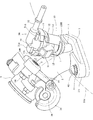
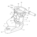
図1は、本実施の形態に係る内燃機関のシリンダヘッド91cの吸気ポート開口端部に連結された吸気管2およびその近傍の斜視図である。
Hereinafter, an embodiment according to the present invention will be described with reference to FIGS.
FIG. 1 is a perspective view of an
吸気管2は、吸気通路2pが湾曲しており、湾曲した外側に分岐して円筒保持部10が突出され、同円筒保持部10に燃料噴射弁Iが嵌入され、ジョイントキャップ30を介して保持される。
吸気管2の上流側端部にはスロットルボディ3が連結される。
The
A
本吸気管2は、円筒保持部10とともに金型により一体に射出成形され、耐熱性に優れ高い剛性があるPPS(ポリフェニレンスルフィド)樹脂からなる。
同吸気管2の構造を、図2ないし図10に基づき、以下説明する。
The
The structure of the
吸気管2の湾曲した吸気通路2pの下流側(シリンダヘッド1側)の開口端部は、取付フランジ2lが形成され、同取付フランジ2lの一対の取付ボス部2lbに金属製カラー4が埋設されている(図9参照)。
他方、吸気管2の吸気通路2pの上流側(スロットルボディ3側)の開口端部は、取付フランジ2uが形成され、同取付フランジ2uの一対の取付ボス部2ubに金属製雌ねじ部材5が埋設されている(図10参照)。
A mounting
On the other hand, an opening end portion on the upstream side (
したがって、本吸気管2は、その下流側の取付フランジ2lをシリンダヘッド1の吸気ポートの下流側開口端部の取付座に連接して取付ボス部2lbの金属製カラー4を間にボルト4Bを通して締結してシリンダヘッド1に取り付けられる(図1参照)。
ボルト4Bの締付けによる負荷は金属製カラー4が受け、樹脂製の取付ボス部2lb自体は締結力を受けず破損などの不具合がなく、緊締して確固として固定することができる。
Therefore, the
The load due to tightening of the
また、吸気管2の上流側の取付フランジ2uには、スロットルボディ3の下流側開口端部が連接され、取付フランジ2uの取付ボス部2ubにスロットルボディ3側の取付ボス部3bを一致させて、スロットルボディ3側からボルト5Bを取付ボス部3bに通し取付ボス部2ubの金属製雌ねじ部材5に螺合し締結してスロットルボディ3が取り付けられる(図1参照)。
ボルト5Bは金属製雌ねじ部材5に螺合して緊締されるので、樹脂製の取付ボス部2ub自体には締結力が加わらず破損などの不具合がなく、緊締して確固として締結することができる。
Further, the downstream opening end of the
Since the
図1に示すように、スロットルボディ3には、吸気通路内のスロットル弁を開閉駆動するスロットルドラム3dが、側方に突出したスロットル回転軸3aに嵌着されている。
スロットルドラム3dにはスロットルワイヤが巻き掛けられ、同スロットルワイヤの牽引によりスロットルドラム3dとともにスロットル弁が回動してスロットル弁開度が調整される。
As shown in FIG. 1, a
A throttle wire is wound around the
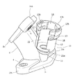
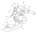
該吸気管2に一体に成形される円筒保持部10は、最も中心軸方向(母線方向)に長尺の中央円筒壁12の下方が径を縮小した下部円筒壁11をなし、中央円筒壁12の上方が外径を大きくした扁平な上部円筒壁13をなし、下部円筒壁11が吸気管2の湾曲した外側部分に一体化し、円筒保持部10が吸気管2から分岐して突出して形成されている。
円筒保持部10の中心軸Cは、吸気通路2pの中心曲線とシリンダヘッド1の吸気ポート内で交差する。
The
The central axis C of the cylindrical holding
円筒保持部10の内部は、中央円筒壁12と上部円筒壁13が同じ内径に形成されており、下部円筒壁11において中央円筒壁12側の中径部11aと吸気通路2p側の小径部11bの2段に縮径されて装着孔が形成され、同装着孔は吸気通路2pに連通している。
Inside the cylindrical holding
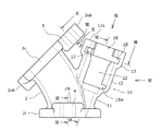
そして円筒保持部10には、中央円筒壁12と上部円筒壁13の一部に欠損部15が切欠かれている。
欠損部15は、上部円筒壁13の開口端面13sから中央円筒壁12にかけて周面の母線方向(中心軸C方向)に凹出して長方形状に形成されている。
The
The
欠損部15は、周方向の幅が上部円筒壁13と中央円筒壁12の内径より小さく、軸(中心軸C)方向の長さが上部円筒壁13と中央円筒壁12の全体にわたる長方形状をなす。
欠損部15の周方向の幅は、燃料噴射弁Iの本体Ibから側方に突出する電装カプラIcの幅長に略等しい。
The missing
The circumferential width of the missing
円筒保持部10の外径が拡大した上部円筒壁13の内面に、2本の横溝17,18が周方向に指向して形成されている。
図8の断面図において、中心軸Cから欠損部15の中央に向けて延びるCP方向を想定すると、一方の横溝17は、短尺で一端が欠損部15に連通しており、横溝17の内側面17sはCP方向に平行な平面と一部円弧面を奥側(欠損部15と反対側)に形成している。
Two
In the cross-sectional view of FIG. 8, assuming a CP direction extending from the central axis C toward the center of the
他方の横溝18は長尺で一端が欠損部15に連通しており、内側面18sは、前記内側面17sに対向してCP方向に平行な平面と長尺の円弧面とからなり、内側面18sの円弧面はCP方向を横溝17側に回り込んで横溝17との間の仕切り部19まで延びている。
この仕切り部19は、図8において中心軸Cを中心にCP方向を時計回りに135度回動した方向に形成されている。
The other
The
図6を参照して、横溝17,18の上面17u,18uは、中心軸Cに対して垂直面をなし、横溝17,18の下面17l,18lは、互いに対応する部分がCP方向に向けて若干下方に傾斜した傾斜面をなしている。
また、横溝17,18の上面17u,18uの欠損部15に連通する端面は、CP方向に向けて上方に傾斜した傾斜面17ue,18ueを形成している。
Referring to FIG. 6,
Further, the end surfaces of the
そして、上部円筒壁13の横溝18の円弧状をなす端部から該上部円筒壁13の開口端面13sに向かい同開口端面13sに開口して縦溝16が周面の母線方向(中心軸C方向)に指向して形成されており、したがって、縦溝16と横溝18がL字状に屈曲して連通している。
縦溝16の周方向幅は、欠損部15の周方向幅と略同じである。
欠損部15は、縦溝の1本を兼ねており、L字状に屈曲するようにして横溝17が連通している。
なお、欠損部15は、他方の横溝18とも連通している。
The
The circumferential width of the
The
Note that the missing
欠損部15の下部が周方向一方(上方の横溝18に対応する方)に幾らか切り込んで水抜き孔15wを形成している。
吸気管2がシリンダヘッド1に取り付けられたときに、吸気管2から分岐し突出した円筒保持部10は、中心軸Cが鉛直線より幾らか傾いており、傾いた中央円筒壁12の最下位置に水抜き孔15wが位置する。
したがって、円筒保持部10内に浸入した水を水抜き孔15wから外部に容易に排出することができる。
The lower part of the
When the
Therefore, the water that has entered the
円筒保持部10の上部円筒壁13の開口端面13sには、CP方向に関して対称位置に長方形の底の浅い嵌装凹部13a,13bが形成されており、図11および図12に図示するように、同嵌装凹部13a,13bには、中央を膨出するように湾曲させた形状の弾性板であるばね部材20,21が嵌装される。
同ばね部材20,21の湾曲した最上部位に凹部20a,21aが形成され、この最上部位の凹部20a,21aは、嵌装凹部13a,13bにばね部材20,21が嵌装されたとき、上部円筒壁13の開口端面13sより上方に飛び出している。
On the opening end face 13s of the upper
以上のような円筒保持部10を備える吸気管2は、PPS樹脂を金型に射出成形して製造される。
円筒保持部10は、その内側と外側の金型に対して横溝17,18を形成するスライダ型を欠損部15側から嵌挿して組み合わせた所に射出成形して形成する。
The
The
2本の横溝17,18は欠損部15に連通しており、横溝17,18の上面17u,18uは、その大部分が中心軸Cに対して垂直面をなし、欠損部15に連通する端面がCP方向に向けて上方に傾斜した傾斜面17ue,18ueを形成しており、かつ下面17l,18lは、互いに対応する部分がCP方向に向けて若干下方に傾斜した傾斜面をなしているので、円筒保持部10の内外の金型にCP方向側からスライダ型を円滑に嵌挿して組み合わせることができ、スライダ型により横溝17,18を容易に成形することができる。
The two
この円筒保持部10に嵌挿保持される燃料噴射弁Iは、図11を参照して、中央円筒壁12の内径より僅かに小さい外径の本体Ibから下方に、下部円筒壁11の小径部11bの内径に略等しい外径の燃料噴射側端部Ieが縮径して延出しており、本体Ibから上方には縮径して燃料導入側端部Iiが延出している。
そして、本体Ibから分岐するようにして制御電力を得るための電装カプラIcが側方に突出している。
Referring to FIG. 11, the fuel injection valve I inserted and held in the
An electrical coupler Ic for branching from the main body Ib to obtain control power projects laterally.
燃料噴射弁Iの下方に延出する燃料噴射側端部Ieにリング状のシール部材25を嵌めて円筒保持部10の下部円筒壁11の中径部11aと小径部11bからなる装着孔に嵌挿する。
シール部材25は、下部円筒壁11の中径部11aに嵌合して小径部11bと中央円筒壁12内部との間をシールする(図16参照)。
A ring-shaped
The
また、燃料噴射弁Iの上方に延出する燃料導入側端部Iiの上端近傍の環状溝にOリング26が嵌合されていて、この上端部にジョイントキャップ30が被せられる(図11,図12参照)。
Further, an O-
ジョイントキャップ30は、樹脂製で燃料噴射弁Iの燃料導入側端部Iiに被せられるキャップ部31とキャップ部31から長尺に延出する燃料導入管32とが一体に形成されたものである。
The
キャップ部31は、有底円筒状をなし、内径が燃料噴射弁Iの上方に延出する燃料導入側端部Iiの外径と略等しい。
このキャップ部31の上壁中央部が上方に膨出して燃料導入管32の基端部が形成され、同基端部から燃料導入管32はキャップ部31の円筒中心軸に対して直角方向に長尺に延出している。
The
The central portion of the upper wall of the
有底円筒状のキャップ部31の下端開口部は外方に反って裾部を形成し、同裾部から一対の係合爪31a,31bが放射方向に互いに対称に突出形成されている。
一方の係合爪31bは燃料導入管32と同じ方向に突出し、他方の係合爪31aは係合爪31bと180度反対側に突出していて、互いに同じ軸方向位置にある。
The bottom end opening of the bottomed
One
係合爪31a,31bの先端縁は同一円弧面をなし、その外径は円筒保持部10の上部円筒壁13の内面に形成された横溝17,18の内径に略等しい。
係合爪31a,31bの周方向幅は、欠損部15および縦溝16の周方向幅より若干小さく、厚さは横溝17,18の溝幅より若干小さい。
The leading edges of the engaging
The circumferential widths of the engaging
また、キャップ部31の上部から下部の係合爪31a,31bと同じようにフランジ部31p,31qが、互いに同じ軸方向位置で突出形成されている。
フランジ部31pは係合爪31aの上方に略同じ形状で若干突出量が大きく平行に突出形成され、フランジ部31qは係合爪31bの上方に略同じ形状で若干突出量が大きく平行に突出形成されるとともに燃料導入管32と部分的に融合して一体化している。
Further, like the
The
フランジ部31pと係合爪31aとの間隔およびフランジ部31qと係合爪31bとの間隔は、互いに同じであり、円筒保持部10における上部円筒壁13の横溝17,18の上面17u,18uと上部円筒壁13の開口端面13sとの間の上下幅より若干大きい。
そして、該係合爪31p,31qの下面には、所定位置に放射方向に長尺で幅狭の凸部31pa,31qaが形成されている。
The interval between the
And on the lower surface of the engaging
ジョイントキャップ30は、以上のような構造をしており、キャップ部31を燃料噴射弁Iの燃料導入側端部Iiに被せた状態で、燃料噴射弁Iを円筒保持部10に取り付ける。
以下、燃料噴射弁Iの円筒保持部10への取り付け手順を、図11ないし図14に従って説明する。
The
Hereinafter, a procedure for attaching the fuel injection valve I to the
燃料噴射弁Iの上方に延出する燃料導入側端部Iiの環状溝にOリング26を嵌合しておき(図11参照)、その燃料導入側端部Iiにジョイントキャップ30のキャップ部31を被せ、予め小組みした状態とする(図12参照)。
An O-
燃料噴射弁Iの燃料導入側端部Iiはジョイントキャップ30の有底円筒状のキャップ部31内に嵌入しOリング26によりシールされる(図16参照)が、燃料噴射弁Iとジョイントキャップ30とは相対的に回動可能であり、当初図12に示すように、燃料噴射弁Iの電装カプラIcが突出した方向にジョイントキャップ30のキャップ部31の係合爪31aおよびフランジ部31pが向き、反対方向には係合爪31bとフランジ部31qおよび燃料導入管32が向くような回動位置に燃料噴射弁Iとジョイントキャップ30を設定して小組みしておく。
The fuel introduction side end Ii of the fuel injection valve I is fitted into the bottomed
次いで、このようにジョイントキャップ30が被せられ小組みされた燃料噴射弁Iを、吸気管2から分岐して突出した円筒保持部10に挿入するが、その際、円筒保持部10の中心軸Cに燃料噴射弁Iの中心軸を一致させ円筒保持部10の欠損部15に燃料噴射弁Iの電装カプラIcを対応させて軸方向に燃料噴射弁Iを挿入する。
Next, the fuel injection valve I, which is covered with the
なお、事前に燃料噴射弁Iの下方に延出する燃料噴射側端部Ieにリング状のシール部材25を嵌めておく。
また、円筒保持部10の上部円筒壁13の開口端面13sの嵌装凹部13a,13bにはばね部材20,21を嵌装しておく。
A ring-shaped
In addition,
こうして、円筒保持部10に燃料噴射弁Iを挿入すると、円筒保持部10の欠損部15に燃料噴射弁Iの本体Ibから側方に突出する電装カプラIcが嵌挿して欠損部15から外部に張り出し、ジョイントキャップ30の係合爪31aは欠損部15に、係合爪31bは上部円筒壁13の縦溝16に嵌挿し、燃料噴射側端部Ieに嵌められたシール部材25が下部円筒壁11の中径部11aに嵌合し燃料噴射側端部Ieの先端側が小径部11bに装着されて、図13に示す嵌挿状態となる。
Thus, when the fuel injection valve I is inserted into the cylindrical holding
この嵌挿状態で、電装カプラIcが欠損部15に嵌挿して外部に張り出しているので、燃料噴射弁Iは円筒保持部10に対して回動が規制されて回動位置が位置決め固定される。
そして、ジョイントキャップ30の係合爪31a,31bは、円筒保持部10の上部円筒壁13の横溝17,18と軸方向位置が一致している。
In this inserted state, the electrical coupler Ic is inserted into the missing
The engaging
そこで、円筒保持部10に対して規制された燃料噴射弁Iをそのままにジョイントキャップ30のみを軸方向上方から視て時計回りに回動すると、ジョイントキャップ30の係合爪31aは上部円筒壁13の内面の横溝17に、係合爪31bは横溝18に入り込み、同時にフランジ部31p,31qは上部円筒壁13の開口端面13sに沿って回動する。
Therefore, when only the
ジョイントキャップ30が円筒保持部10に対して回動する途中で、上部円筒壁13の開口端面13sの嵌装凹部13a,13bにそれぞれ嵌装されたばね部材20,21の上方に飛び出した部分にフランジ部31p,31qの下面が接して、ばね部材20,21の弾性力によりフランジ部31p,31qが上方に押圧されてジョイントキャップ30が上方に付勢され係合爪31a,31bが横溝17,18の上面17u,18uに圧接される。
In the middle of the rotation of the
そして、ジョイントキャップ30が円筒保持部10に対して約90度回動したところで、ばね部材20,21の最上部位の凹部20a,21aにフランジ部31p,31qの下面の凸部31pa,31qaがそれぞれ嵌合して回動位置決めがなされる(図15参照)。
また、ジョイントキャップ30の係合爪31aが円筒保持部10の横溝17,18間の仕切り部19により約90度回動位置で規制される。
When the
Further, the engaging
こうして図14に示すような状態で、燃料噴射弁Iがジョイントキャップ30を介して円筒保持部10に挿入されて取り付けられ、吸気管2から分岐して突出した円筒保持部10に対して燃料噴射弁Iの本体Ibに設けられた電装カプラIcとジョイントキャップ30の燃料導入管32とが、互いに90度の開き角度を持って所定方向に位置決めされて突出している。
In this way, in the state shown in FIG. 14, the fuel injection valve I is inserted and attached to the cylindrical holding
ジョイントキャップ30の燃料導入管32には、燃料配管が接続されて燃料が燃料導入管32を通って燃料噴射弁Iに供給され、電装カプラIcに制御配線のコネクタが接合されて燃料噴射弁Iの弁が開閉制御され、制御されたタイミングで燃料噴射側端部Ieから燃料を吸気通路2p内に噴射することができる。
A fuel pipe is connected to the
燃料噴射弁Iの本体Ibを円筒保持部10が収容し囲繞するので、燃料噴射弁Iが十分保護されるとともに、燃料噴射弁Iの作動音を遮断することができる。
吸気管2に突出形成された円筒保持部10は、燃料噴射弁Iの本体Ibを中央円筒壁12および上部円筒壁13が囲繞する円筒形状を形成しているので、該円筒保持部10は比較的薄肉の筒壁であっても強度および剛性を確保することができ、燃料噴射弁Iをコンパクトに取り付けることができる。
Since the
Since the
燃料噴射弁Iに突設される電装カプラIcを嵌挿できる欠損部15が円筒保持部10に形成され、円筒保持部10の上部円筒壁13の内周面に、ジョイントキャップ30の係合爪31b(31a)が係合する縦溝16(欠損部15)と横溝18(17)がL字状に連通して形成されているので、燃料噴射弁Iにジョイントキャップ30を被せ予め小組みした状態で、電装カプラIcを欠損部15に対応させて円筒保持部10に燃料噴射弁Iを挿入すると同時に、ジョイントキャップ30の係合爪31b(31a)を円筒保持部10の縦溝16(欠損部15)に嵌挿するようにジョイントキャップ30を円筒保持部10に軸方向に挿入し、ジョイントキャップ30を回動して係合爪31a,31bを横溝17,18に係合保持させることで、簡単に燃料噴射弁Iを取り付けることができる。
A
電装カプラIcは円筒保持部10の欠損部15に嵌挿されて燃料噴射弁Iとともに回動方向の位置決めがなされるので、位置決めに特別の部材を必要としない。
円筒保持部10への燃料噴射弁Iの取り付けに、締結ボルト等を必要とせず、取付作業を容易とするとともに、締結ボス部等を設けないので燃料噴射弁Iをコンパクトに保持することができる。
円筒保持部10の欠損部15が縦溝の1本を兼ねるので、円筒保持部10の形状が簡素化され、よりコンパクトになる。
Since the electrical coupler Ic is fitted into the missing
The attachment of the fuel injection valve I to the cylindrical holding
Since the missing
円筒保持部10にジョイントキャップ30が係合保持される際に、円筒保持部10の開口端面13sとジョイントキャップ30のフランジ部31p,31qとの間にばね部材20,21が介装され、同ばね部材20,21によりジョイントキャップ30が円筒保持部10に対して上方に付勢されるので、上方に付勢されたジョイントキャップ30は円筒保持部10の横溝17,18に係合した係合爪31a,31bが横溝17,18の軸方向に垂直な上面17u,18uに押さえつけられるため、摩擦抵抗が大きくなりジョイントキャップ30の回動を抑制して係合を安定化する。
When the
さらに、円筒保持部10の開口端面13sの嵌装凹部13a,13bに嵌装係止されたばね部材20,21には、開口端面13sより飛び出した最上部位に凹部20a,21aが形成され、ジョイントキャップ30のフランジ部31p,31qの下面には凸部31pa,31qaが形成されて、円筒保持部10に対するジョイントキャップ30の回動によりばね部材20,21の最上部位の凹部20a,21aにフランジ部31p,31qの下面の凸部31pa,31qaが嵌合して回動位置決めがなされるので、円筒保持部10に対するジョイントキャップ30の所定の回動位置への位置合せ作業が容易かつ確実にできる。
Further, the
なお、ばね部材20,21に凸部を形成し、フランジ部31p,31qの下面に凹部を形成してもよい。
In addition, you may form a convex part in the
ジョイントキャップ30が円筒保持部10に係合保持された状態で、ジョイントキャップ30に突設され燃料配管が接続される燃料導入管32が、円筒保持部10の開口端面13sより上方に位置しているので、ジョイントキャップ30の燃料導入管32の向きを自由に設定することができる。
In a state where the
本実施の形態に係る燃料噴射弁の取付構造を適用したパワーユニット搭載の自動二輪車70の部分側面図を図17に示し説明する。
A partial side view of a
本自動二輪車70の車体フレームは、車体全部のヘッドパイプ72の上部から後方へ斜め下向きに傾斜して1本のメインフレーム73が延出し、同メインフレーム73の後部に左右一対のピボットブラケット74,74が下方に延出するように固着されている。
メインフレーム73の後部でピボットブラケット74,74の固着位置より前辺りから左右一対のシートレール75,75が後方へ斜め上向きに延出し途中で略水平に屈曲して後端に至っている。
このシートレール75,75の屈曲部位辺りとピボットブラケット74,74との間にミドルフレーム76,76が介装されている。
The body frame of the
At the rear of the
Middle frames 76 and 76 are interposed between the bent portions of the seat rails 75 and 75 and the
以上のような車体フレームの左右一対のシートレール75,75間に収納ボックス100と燃料タンク102が前後に架設され、収納ボックス100と燃料タンク102の上方をシート78が開閉自在に覆っている。
収納ボックス100の下部にはバッテリ101が配設され、燃料タンク102の前部には燃料ポンプ103が設けられている。
Between the pair of left and right seat rails 75, 75 of the vehicle body frame as described above, the
A
車体前部においてヘッドパイプ72に軸支されて上方にハンドルが設けられ、下方にフロントフォーク80が延びてその下端に前輪81が軸支されている。
車体中央のピボットブラケット74,74にピボット軸82によりリヤフォーク83が前端を軸支されて後方に延びており、同リヤフォーク83の後端部に後輪84が軸支されている。
ピボット軸82を中心に上下に揺動するリヤフォーク83の後部とシートレール75,75との間にリヤクッション85,85が介装されている。
A handlebar is provided above and supported by the
A
Rear cushions 85 and 85 are interposed between a
そしてメインフレーム73の下方でかつピボットブラケット74,74の前方にパワーユニット90が懸架される。
パワーユニット90は、内燃機関91を前半部に、変速機92を後半部に位置して一体に構成されたものであり、変速機92の出力軸93と後輪84の後車軸間にチェーン94が架渡されて、出力軸93の回転動力がチェーン94を介して後輪84に伝達されて後輪84が回転して走行する。
The
The
内燃機関91は、単気筒の4サイクル内燃機関で、ユニットケース91aの前面からシリンダブロック91b、シリンダヘッド91cおよびシリンダヘッドカバー91dが重ねられて略水平に近い状態にまで大きく前傾した姿勢で突出している。
The
この前傾したシリンダヘッド91cにおける上側の吸気ポートから本吸気管2が上方に延出している。
吸気管2は下流側開口端部がシリンダヘッド91cの吸気ポート開口に結合されて、上方に延出しながら前方に湾曲して上流側開口端部がスロットルボディ3に結合される。
The
The
スロットルボディ3の前方には斜め上方にエアクリーナボックス108が、メインフレーム73にブラケット109を介して吊設されており、このエアクリーナボックス108とスロットルボディ3がコネクティングチューブ107により連結されている。
An
以上のように吸気管2が内燃機関91の前傾したシリンダヘッド91cに取り付けられるので、吸気管2より分岐した円筒保持部10は、後方斜め上向きに傾いて突出している。
したがって、円筒保持部10の欠損部15は車体幅方向の左側に向いており、同欠損部15から燃料噴射弁Iの電装カプラIcが車体左方に突出する。
後方斜め上向きに傾いた円筒保持部10の最下位置に水抜き孔15wが位置し、円筒保持部10内に浸入した水を水抜き孔15wから外部に排出することができる。
As described above, since the
Accordingly, the missing
The
そして、燃料噴射弁Iの上に被せられるジョイントキャップ30に一体に形成される燃料導入管32は、後方に向けて突出される。
車体後部には、燃料タンク102が搭載されており、燃料タンク102の前部に設けられた燃料ポンプ103とジョイントキャップ30の後方に突出した燃料導入管32とが、燃料ホース104により連結される。
The
A
燃料ポンプ103に後端を結合された燃料ホース104は、左側シートレール75の内面に沿って前方に延び、さらにメインフレーム73の後半部左側面を前方に延びて燃料噴射弁Iの上に被せられるジョイントキャップ30の後方に突出した燃料導入管32にコネクタ105を介して前端を結合している。
このように、ジョイントキャップ30の燃料導入管32は、車体後方の燃料タンク102のある方を向いて取り付けられるので、燃料ホース104を短くすることができる。
The
Thus, the
円筒保持部10の欠損部15が車体横方向(左方向)に向いて開口しており、したがって電装カプラIcが車体横向きとなり、車体後方に延びる燃料ホース104と干渉することがないため、円筒保持部10が高さを抑えられて、結果的にメインフレーム73を下げることができ、跨ぎ性の向上に寄与する。
Since the missing
以上の実施の形態では、ジョイントキャップ30にフランジ部31p,31qが部分的に突出形成されていたが、全周に亘って形成された別の実施の形態について図18および図19に図示し説明する。
本実施の形態は、ジョイントキャップのみが、前記実施の形態と異なるので、他の部材は前記実施の形態と同じ符号を用いて示すこととする。
In the above embodiment, the
In the present embodiment, only the joint cap is different from the above embodiment, and therefore, other members are indicated by the same reference numerals as those in the above embodiment.
本ジョイントキャップ50における有底円筒状をなすキャップ部51、その下部の係合爪51a,51bおよび燃料導入管52は、前記ジョイントキャップ30と同じ形状であるが、フランジ部51fはキャップ部51の上部に全周に亘って円板部51faが円筒保持部10の上部円筒壁13の外周縁を越える所まで延出して形成されるとともに、同円板部51faの外周部が下方に屈曲して円環部51fbが形成されている。
なお、円板部51faの下面には所定位置に凸部51fc,51fdが、前記ジョイントキャップ30と同様に形成されている。
The
In addition, convex portions 51fc and 51fd are formed at predetermined positions on the lower surface of the disc portion 51fa in the same manner as the
したがって、燃料噴射弁Iがジョイントキャップ50を介して円筒保持部10に挿入されて取り付けられると、ジョイントキャップ50のフランジ部51fが円筒保持部10の上部円筒壁13の開口を全面に亘って覆うことができ、水や砂などの異物が円筒保持部10に入るのを防止することができるとともに、燃料噴射弁の作動音をより確実に遮断することができる。
Therefore, when the fuel injection valve I is inserted and attached to the cylindrical holding
なお、以上の実施の形態では、円筒保持部10が吸気管2に一体に突出形成されたが、本発明は、シリンダヘッドに円筒保持部が一体に突出形成されるものあってもよい。
In the above embodiment, the
E…内燃機関、I…燃料噴射弁、Ib…本体、Ic…電装カプラ、
1…シリンダヘッド、2…吸気管、3…スロットルボディ、4…金属製カラー、5…金属製雌ねじ部材、
10…円筒保持部、11…下部円筒壁、12…中央円筒壁、13…上部円筒壁、13s…開口端面、15…欠損部、15w…水抜き孔、16…縦溝、17…横溝、17u…上面、18…横溝、18u…上面、20, 21…ばね部材、20a,21a…凹部、25…シール部材、26…Oリング、
30…ジョイントキャップ、31…キャップ部、31a,31b…係合爪、31p,31q…フランジ部、32…燃料導入管、
50…ジョイントキャップ、51a,51b…係合爪、51f…フランジ部、52…燃料導入管。
E ... Internal combustion engine, I ... Fuel injection valve, Ib ... Main body, Ic ... Electrical component coupler,
DESCRIPTION OF SYMBOLS 1 ... Cylinder head, 2 ... Intake pipe, 3 ... Throttle body, 4 ... Metal collar, 5 ... Metal internal thread member,
DESCRIPTION OF
30 ... Joint cap, 31 ... Cap part, 31a, 31b ... Engagement claw, 31p, 31q ... Flange part, 32 ... Fuel introduction pipe,
50 ... joint cap, 51a, 51b ... engaging claw, 51f ... flange, 52 ... fuel introduction pipe.
Claims (8)
前記保持部(10)は、前記燃料噴射弁(I)の本体(Ib)の側方を円筒壁(12)が囲繞する円筒形状に形成された円筒保持部(10)とされ、
該円筒保持部(10)の円筒壁(12)の一部に、前記燃料噴射弁(I)の本体(Ib)から側方に突出する電装カプラ(Ic)が嵌挿して外部に張り出すことができる欠損部(15)が、前記円筒壁(12)の開口端面(13s)から該円筒保持部(10)の中心軸(C)方向に長方形状に切り欠いて形成され、
前記ジョイントキャップ(30)の外周に係合爪(31a,31b)が放射方向に突出形成され、
前記円筒保持部(10)の円筒壁(12)の内面に、前記係合爪(31a,31b)を係合するための横溝(17,18)が周方向に指向して形成されるとともに、同横溝(17,18)の端部から該円筒壁(12)の開口端面(13s)に向かい同開口端面(13s)に開口して縦溝(16)が該円筒保持部(10)の中心軸(C)方向に指向して形成され、
前記ジョイントキャップ(30)は、前記係合爪(31a,31b)より上方にフランジ部(31p,31q)が形成され、
前記円筒保持部(10)に前記ジョイントキャップ(30)が係合保持される際に、前記円筒保持部(10)の開口端面(13s)と前記ジョイントキャップ(30)のフランジ部との間に弾性部材(20,21)が介装され、同弾性部材(20,21)により前記ジョイントキャップ(30)が前記円筒保持部(10)に対して上方に付勢され、
前記円筒保持部(10)の開口端面(13s)の係止部(13a,13b)に係止された前記弾性部材(20,21)と前記ジョイントキャップ(30)のフランジ部(31p,31q)との互いに対向する所定部分に凹部(20a,21a)と凸部(31pa,31qa)がそれぞれ形成され、同凹部(20a,21a)と凸部(31pa,31qa)の互いの嵌合により前記円筒保持部(10)に対して前記ジョイントキャップ(30)が所定の回動位置に位置決めされて係合保持されることを特徴とする燃料噴射弁の取付構造。 The end of the fuel injection side of the fuel injection valve (I) is inserted into the mounting hole (11a, 11b) formed at a predetermined location on the intake pipe (2) or the cylinder head (1) that guides intake air to the combustion chamber of the internal combustion engine. The fuel injection side end of the fuel injection valve (I) projects integrally with the intake pipe (2) or the cylinder head (1) via a joint cap (30) that covers the end of the fuel introduction side. In the fuel injection valve (I) mounting structure held by the formed holding portion (10),
The holding part (10) is a cylindrical holding part (10) formed in a cylindrical shape in which a cylindrical wall (12) surrounds the side of the main body (Ib) of the fuel injection valve (I),
Some of the cylindrical wall (12) of the cylindrical holding portion (10), to protrude to the outside fitted electric coupler (Ic) is projecting laterally from the body (Ib) of the fuel injection valve (I) The missing part (15) that can be formed is cut out in a rectangular shape from the opening end face (13s) of the cylindrical wall (12) in the central axis (C) direction of the cylindrical holding part (10) ,
Engaging claws (31a, 31b) are formed to project radially in the outer periphery of the joint cap (30),
On the inner surface of the cylindrical wall (12) of the cylindrical holder (10), lateral grooves (17, 18) for engaging the engaging claws (31a, 31b) are formed in the circumferential direction, and The vertical groove (16) opens to the opening end surface (13s) of the cylindrical wall (12) from the end of the horizontal groove (17, 18) toward the opening end surface (13s) of the cylindrical wall (12). Formed in the direction of the axis (C),
The joint cap (30) is formed with flange portions (31p, 31q) above the engaging claws (31a, 31b),
When the joint cap (30) is engaged and held by the cylindrical holding portion (10), between the opening end surface (13s) of the cylindrical holding portion (10) and the flange portion of the joint cap (30). The elastic member (20, 21) is interposed, the joint cap (30) is urged upward with respect to the cylindrical holding portion (10) by the elastic member (20, 21),
The elastic member (20, 21) locked to the locking portion (13a, 13b) of the opening end surface (13s) of the cylindrical holding portion (10) and the flange portion (31p, 31q) of the joint cap (30) The concave portions (20a, 21a) and the convex portions (31pa, 31qa) are respectively formed in predetermined portions facing each other, and the cylindrical portions are formed by fitting the concave portions (20a, 21a) and the convex portions (31pa, 31qa) to each other. A fuel injection valve mounting structure , wherein the joint cap (30) is positioned and engaged with a holding portion (10) at a predetermined rotational position .
前記円筒保持部(10)の円筒壁(12)の内面に、前記係合爪(31a,31b)を係合するための前記横溝(17,18)が複数本周方向に指向して形成されるとともに、同横溝(17,18)の端部から該円筒壁(12)の開口端面(13s)に向かい同開口端面(13s)に開口して前記縦溝(16)が複数本該円筒保持部(10)の中心軸(C)方向に指向して形成されることを特徴とする請求項1記載の燃料噴射弁の取付構造。 The engagement claws (31a, 31b) on the outer periphery of the joint cap (30) has a plurality of protruding radially,
A plurality of the lateral grooves (17, 18) for engaging the engaging claws (31a, 31b) are formed on the inner surface of the cylindrical wall (12) of the cylindrical holding portion (10) so as to be oriented in the circumferential direction. Rutotomoni, the transverse grooves (17, 18) of the opening end face of the cylindrical wall (12) from the end (13s) opposite the longitudinal grooves (16) are held a plurality of cylindrical open to the open end face (13s) The fuel injection valve mounting structure according to claim 1, wherein the fuel injection valve is oriented in the direction of the central axis (C) of the portion (10) .
Priority Applications (1)
| Application Number | Priority Date | Filing Date | Title |
|---|---|---|---|
| JP2007274790A JP4759552B2 (en) | 2007-10-23 | 2007-10-23 | Fuel injection valve mounting structure |
Applications Claiming Priority (1)
| Application Number | Priority Date | Filing Date | Title |
|---|---|---|---|
| JP2007274790A JP4759552B2 (en) | 2007-10-23 | 2007-10-23 | Fuel injection valve mounting structure |
Publications (2)
| Publication Number | Publication Date |
|---|---|
| JP2009103024A JP2009103024A (en) | 2009-05-14 |
| JP4759552B2 true JP4759552B2 (en) | 2011-08-31 |
Family
ID=40704965
Family Applications (1)
| Application Number | Title | Priority Date | Filing Date |
|---|---|---|---|
| JP2007274790A Expired - Fee Related JP4759552B2 (en) | 2007-10-23 | 2007-10-23 | Fuel injection valve mounting structure |
Country Status (1)
| Country | Link |
|---|---|
| JP (1) | JP4759552B2 (en) |
Families Citing this family (6)
| Publication number | Priority date | Publication date | Assignee | Title |
|---|---|---|---|---|
| JP5244638B2 (en) * | 2009-01-30 | 2013-07-24 | 本田技研工業株式会社 | Inlet pipe |
| JP5468446B2 (en) * | 2010-03-31 | 2014-04-09 | 本田技研工業株式会社 | V-type engine fuel supply system |
| CN106089525B (en) * | 2016-08-23 | 2018-08-07 | 力帆实业(集团)股份有限公司 | Motorcycle with electronic fuel injection system single channel oil rail |
| WO2020145158A1 (en) * | 2019-01-07 | 2020-07-16 | 三菱自動車工業株式会社 | Cylinder head |
| JP7229334B2 (en) * | 2019-03-01 | 2023-02-27 | 本田技研工業株式会社 | Intake structure of internal combustion engine |
| US20240209819A1 (en) * | 2021-10-19 | 2024-06-27 | Hitachi Astemo, Ltd. | Support structure for fuel injection valve |
Family Cites Families (9)
| Publication number | Priority date | Publication date | Assignee | Title |
|---|---|---|---|---|
| JPS5125042Y2 (en) * | 1971-07-16 | 1976-06-26 | ||
| JPS5750537Y2 (en) * | 1977-07-27 | 1982-11-05 | ||
| DE4329774A1 (en) * | 1993-09-03 | 1995-03-09 | Bosch Gmbh Robert | Device for the fixing and securing of a valve |
| JPH07167020A (en) * | 1993-12-13 | 1995-07-04 | Nissan Motor Co Ltd | Fuel injector mounting device |
| JP2599085Y2 (en) * | 1993-12-13 | 1999-08-30 | 愛知機械工業株式会社 | Mounting structure for fuel injector cap |
| JP3472673B2 (en) * | 1997-01-06 | 2003-12-02 | 矢崎総業株式会社 | Waterproof connector |
| JP2001234835A (en) * | 2000-02-28 | 2001-08-31 | Fuji Heavy Ind Ltd | Mounting structure for intake manifold and injector |
| JP4405111B2 (en) * | 2001-08-06 | 2010-01-27 | 株式会社ケーヒン | Fuel injector holding device |
| JP4636328B2 (en) * | 2006-01-20 | 2011-02-23 | アイシン精機株式会社 | Intake control device |
-
2007
- 2007-10-23 JP JP2007274790A patent/JP4759552B2/en not_active Expired - Fee Related
Also Published As
| Publication number | Publication date |
|---|---|
| JP2009103024A (en) | 2009-05-14 |
Similar Documents
| Publication | Publication Date | Title |
|---|---|---|
| JP4759552B2 (en) | Fuel injection valve mounting structure | |
| EP1647701B1 (en) | Air cleaner | |
| US8056535B2 (en) | Intake control system for general-purpose engine | |
| JP2004060552A (en) | Motorcycle engine fuel supply system | |
| JP4555413B2 (en) | Fuel injection device for backbone type motorcycle | |
| JP2008248853A (en) | Air cleaner for internal combustion engine | |
| US11306686B2 (en) | Fluid control valve | |
| TWI230668B (en) | Air inlet device of engine | |
| JP2009162065A (en) | Engine intake passage structure | |
| JP2019211018A (en) | Fluid control valve | |
| US11236712B2 (en) | Air cleaner assembly | |
| JP2009162065A5 (en) | ||
| EP1162132A2 (en) | Fuel pipeline connecting structure | |
| KR101296961B1 (en) | Structure of Tumble type VCM valve | |
| JP4325829B2 (en) | Fuel piping structure of fuel injection engine | |
| JP5995775B2 (en) | Resin cover mounting structure | |
| JP2004036482A (en) | Bifuel internal combustion engine | |
| CN214304064U (en) | Throttle valve body of general electric injection motorcycle | |
| JP2003074379A (en) | Engine intake air control system | |
| JP2003074380A (en) | Engine intake air control system | |
| JP5513943B2 (en) | Power unit intake system structure | |
| CN1991161B (en) | Fuel injection system and fuel injection valve device used in fuel injection system | |
| JP5664422B2 (en) | Fuel pump mounting structure and motorcycle | |
| JP2001097054A (en) | Oil feeding system | |
| JP2003074378A (en) | Engine intake air control system |
Legal Events
| Date | Code | Title | Description |
|---|---|---|---|
| RD04 | Notification of resignation of power of attorney |
Free format text: JAPANESE INTERMEDIATE CODE: A7424 Effective date: 20090501 |
|
| A621 | Written request for application examination |
Free format text: JAPANESE INTERMEDIATE CODE: A621 Effective date: 20091126 |
|
| A977 | Report on retrieval |
Free format text: JAPANESE INTERMEDIATE CODE: A971007 Effective date: 20101222 |
|
| A131 | Notification of reasons for refusal |
Free format text: JAPANESE INTERMEDIATE CODE: A131 Effective date: 20101228 |
|
| A521 | Written amendment |
Free format text: JAPANESE INTERMEDIATE CODE: A523 Effective date: 20110228 |
|
| A01 | Written decision to grant a patent or to grant a registration (utility model) |
Free format text: JAPANESE INTERMEDIATE CODE: A01 Effective date: 20110510 |
|
| A61 | First payment of annual fees (during grant procedure) |
Free format text: JAPANESE INTERMEDIATE CODE: A61 Effective date: 20110606 |
|
| R150 | Certificate of patent or registration of utility model |
Free format text: JAPANESE INTERMEDIATE CODE: R150 |
|
| FPAY | Renewal fee payment (event date is renewal date of database) |
Free format text: PAYMENT UNTIL: 20140610 Year of fee payment: 3 |
|
| LAPS | Cancellation because of no payment of annual fees |