JP7229334B2 - Intake structure of internal combustion engine - Google Patents
Intake structure of internal combustion engine Download PDFInfo
- Publication number
- JP7229334B2 JP7229334B2 JP2021504059A JP2021504059A JP7229334B2 JP 7229334 B2 JP7229334 B2 JP 7229334B2 JP 2021504059 A JP2021504059 A JP 2021504059A JP 2021504059 A JP2021504059 A JP 2021504059A JP 7229334 B2 JP7229334 B2 JP 7229334B2
- Authority
- JP
- Japan
- Prior art keywords
- intake
- internal combustion
- combustion engine
- passage
- intake structure
- Prior art date
- Legal status (The legal status is an assumption and is not a legal conclusion. Google has not performed a legal analysis and makes no representation as to the accuracy of the status listed.)
- Active
Links
- 238000002485 combustion reaction Methods 0.000 title claims description 51
- 239000000446 fuel Substances 0.000 claims description 24
- 238000005452 bending Methods 0.000 claims description 10
- 238000002347 injection Methods 0.000 claims description 6
- 239000007924 injection Substances 0.000 claims description 6
- 238000011144 upstream manufacturing Methods 0.000 claims description 6
- 230000002093 peripheral effect Effects 0.000 description 7
- 239000002828 fuel tank Substances 0.000 description 3
- 239000000567 combustion gas Substances 0.000 description 1
- 238000009792 diffusion process Methods 0.000 description 1
- 239000000463 material Substances 0.000 description 1
- 230000004048 modification Effects 0.000 description 1
- 238000012986 modification Methods 0.000 description 1
- 238000000638 solvent extraction Methods 0.000 description 1
- 238000009834 vaporization Methods 0.000 description 1
- 230000008016 vaporization Effects 0.000 description 1
Images


Classifications
-
- F—MECHANICAL ENGINEERING; LIGHTING; HEATING; WEAPONS; BLASTING
- F02—COMBUSTION ENGINES; HOT-GAS OR COMBUSTION-PRODUCT ENGINE PLANTS
- F02B—INTERNAL-COMBUSTION PISTON ENGINES; COMBUSTION ENGINES IN GENERAL
- F02B31/00—Modifying induction systems for imparting a rotation to the charge in the cylinder
- F02B31/04—Modifying induction systems for imparting a rotation to the charge in the cylinder by means within the induction channel, e.g. deflectors
-
- F—MECHANICAL ENGINEERING; LIGHTING; HEATING; WEAPONS; BLASTING
- F02—COMBUSTION ENGINES; HOT-GAS OR COMBUSTION-PRODUCT ENGINE PLANTS
- F02D—CONTROLLING COMBUSTION ENGINES
- F02D9/00—Controlling engines by throttling air or fuel-and-air induction conduits or exhaust conduits
- F02D9/08—Throttle valves specially adapted therefor; Arrangements of such valves in conduits
- F02D9/10—Throttle valves specially adapted therefor; Arrangements of such valves in conduits having pivotally-mounted flaps
-
- F—MECHANICAL ENGINEERING; LIGHTING; HEATING; WEAPONS; BLASTING
- F02—COMBUSTION ENGINES; HOT-GAS OR COMBUSTION-PRODUCT ENGINE PLANTS
- F02F—CYLINDERS, PISTONS OR CASINGS, FOR COMBUSTION ENGINES; ARRANGEMENTS OF SEALINGS IN COMBUSTION ENGINES
- F02F1/00—Cylinders; Cylinder heads
- F02F1/24—Cylinder heads
- F02F1/42—Shape or arrangement of intake or exhaust channels in cylinder heads
-
- F—MECHANICAL ENGINEERING; LIGHTING; HEATING; WEAPONS; BLASTING
- F02—COMBUSTION ENGINES; HOT-GAS OR COMBUSTION-PRODUCT ENGINE PLANTS
- F02M—SUPPLYING COMBUSTION ENGINES IN GENERAL WITH COMBUSTIBLE MIXTURES OR CONSTITUENTS THEREOF
- F02M35/00—Combustion-air cleaners, air intakes, intake silencers, or induction systems specially adapted for, or arranged on, internal-combustion engines
- F02M35/10—Air intakes; Induction systems
- F02M35/104—Intake manifolds
-
- F—MECHANICAL ENGINEERING; LIGHTING; HEATING; WEAPONS; BLASTING
- F02—COMBUSTION ENGINES; HOT-GAS OR COMBUSTION-PRODUCT ENGINE PLANTS
- F02M—SUPPLYING COMBUSTION ENGINES IN GENERAL WITH COMBUSTIBLE MIXTURES OR CONSTITUENTS THEREOF
- F02M35/00—Combustion-air cleaners, air intakes, intake silencers, or induction systems specially adapted for, or arranged on, internal-combustion engines
- F02M35/16—Combustion-air cleaners, air intakes, intake silencers, or induction systems specially adapted for, or arranged on, internal-combustion engines characterised by use in vehicles
-
- F—MECHANICAL ENGINEERING; LIGHTING; HEATING; WEAPONS; BLASTING
- F02—COMBUSTION ENGINES; HOT-GAS OR COMBUSTION-PRODUCT ENGINE PLANTS
- F02M—SUPPLYING COMBUSTION ENGINES IN GENERAL WITH COMBUSTIBLE MIXTURES OR CONSTITUENTS THEREOF
- F02M69/00—Low-pressure fuel-injection apparatus ; Apparatus with both continuous and intermittent injection; Apparatus injecting different types of fuel
- F02M69/04—Injectors peculiar thereto
-
- Y—GENERAL TAGGING OF NEW TECHNOLOGICAL DEVELOPMENTS; GENERAL TAGGING OF CROSS-SECTIONAL TECHNOLOGIES SPANNING OVER SEVERAL SECTIONS OF THE IPC; TECHNICAL SUBJECTS COVERED BY FORMER USPC CROSS-REFERENCE ART COLLECTIONS [XRACs] AND DIGESTS
- Y02—TECHNOLOGIES OR APPLICATIONS FOR MITIGATION OR ADAPTATION AGAINST CLIMATE CHANGE
- Y02T—CLIMATE CHANGE MITIGATION TECHNOLOGIES RELATED TO TRANSPORTATION
- Y02T10/00—Road transport of goods or passengers
- Y02T10/10—Internal combustion engine [ICE] based vehicles
- Y02T10/12—Improving ICE efficiencies
Landscapes
- Engineering & Computer Science (AREA)
- Chemical & Material Sciences (AREA)
- Combustion & Propulsion (AREA)
- Mechanical Engineering (AREA)
- General Engineering & Computer Science (AREA)
- Cylinder Crankcases Of Internal Combustion Engines (AREA)
- Fuel-Injection Apparatus (AREA)
Description
本発明は内燃機関の吸気構造に関する。 The present invention relates to an intake structure for an internal combustion engine.
インジェクタ(燃料噴射弁)により吸気ポートへ燃料を噴射する内燃機関においては、吸気ポートの周壁に燃料が付着する場合があり、これにより内燃機関の燃焼効率が低下する場合がある。特許文献1にはその対策として、吸気ポートに燃料の拡散・気化を促進する部位を形成した構造が開示されている。
2. Description of the Related Art In an internal combustion engine that injects fuel into an intake port using an injector (fuel injection valve), fuel may adhere to the peripheral wall of the intake port, which may reduce the combustion efficiency of the internal combustion engine. As a countermeasure,
インジェクタから噴射された燃料を効率的に燃焼室に供給するために、インジェクタをできるだけ燃焼室に近い位置に配置することが有効である。しかし、インジェクタを燃焼室により近い位置に配置するためには、シリンダヘッドやヘッドカバーとの干渉に関する構造的な課題がある。 In order to efficiently supply the fuel injected from the injector to the combustion chamber, it is effective to arrange the injector as close to the combustion chamber as possible. However, in order to place the injector closer to the combustion chamber, there is a structural problem related to interference with the cylinder head and head cover.
本発明の目的は、インジェクタを燃焼室により近い位置に配置可能な構造を提供することにある。 SUMMARY OF THE INVENTION It is an object of the present invention to provide a structure that allows the injector to be positioned closer to the combustion chamber.
請求項1の本発明によれば、
ヘッドカバー(31)が設けられたシリンダヘッド(32)とスロットル(12)の間に接続され、吸気通路(11a)を形成する通路部材(11)と、
前記通路部材(11)に設けられ、燃料を噴射するインジェクタ(16)が取り付けられる取付ボス(113)と、
を備え、鞍乗型車両(1)に搭載される内燃機関(3)の吸気構造(10)であって、
前記通路部材(11)は、
前記吸気通路(11a)の通路方向を、前記鞍乗型車両(1)の車幅方向に屈曲させる屈曲部(110a)と、
前記シリンダヘッド(32)に接続される接続面(111a)を有するフランジ部(111)と、を含み、
前記取付ボス(113)は、
前記屈曲部(110a)の屈曲の内外方向(BD)で、内側(IN)よりも外側(OUT)に偏った位置において前記フランジ部(111)に一体に形成され、かつ、
前記通路部材(11)を前記接続面(111a)の側から見た場合、シリンダ軸線方向(L1')に対して交差する方向(L2)に突出し、
前記シリンダヘッド(32)は、
前記通路部材(11)の前記接続面(111a)が接続される接続面(32a)と、
前記接続面(32a)に隣接した部位に形成され、前記インジェクタ(16)を避ける第一の避け部(32b)と、を含む、
ことを特徴とする内燃機関の吸気構造が提供される。
According to the present invention of
a passage member (11) connected between a cylinder head (32) provided with a head cover (31) and a throttle (12) to form an intake passage (11a);
a mounting boss (113) provided in the passage member (11) to which an injector (16) for injecting fuel is mounted;
An intake structure (10) for an internal combustion engine (3) mounted on a straddle-type vehicle (1), comprising:
The passage member (11) is
a bending portion (110a) that bends the passage direction of the intake passage (11a) in the vehicle width direction of the straddle-type vehicle (1);
a flange portion (111) having a connection surface (111a) connected to the cylinder head (32),
The mounting boss (113) is
formed integrally with the flange portion (111) at a position biased outward (OUT) from the inner side (IN) in the inward-outward direction (BD) of the bend of the bent portion (110a), and
When the passage member (11) is viewed from the connecting surface (111a) side, the passage member (11) protrudes in a direction (L2) intersecting with the cylinder axial direction (L1'),
The cylinder head (32) is
a connection surface (32a) to which the connection surface (111a) of the passage member (11) is connected;
a first avoidance portion (32b) formed adjacent to the connection surface (32a) and avoiding the injector (16);
There is provided an intake structure for an internal combustion engine characterized by:
請求項2の本発明によれば、
前記取付ボス(113)は、前記インジェクタ(16)が挿入され、該インジェクタの燃料噴射方向(L2)を規定する穴(113a)を有し、
前記穴(113a)の軸線方向(L2)は、前記吸気通路(11a)の中心線(CT)からオフセットしている。According to the present invention of
The mounting boss (113) has a hole (113a) into which the injector (16) is inserted and defines a fuel injection direction (L2) of the injector,
The axial direction (L2) of the hole (113a) is offset from the center line (CT) of the intake passage (11a).
請求項3の本発明によれば、
前記スロットル(12)は、前記通路部材(11)の上流側の端部(112)に取り付けられ、
前記スロットル(12)のドラム部(121)は、前記屈曲部(110a)の屈曲の内外方向(BD)で、内側(IN)に位置している。According to the present invention of
The throttle (12) is attached to an upstream end (112) of the passage member (11),
The drum portion (121) of the throttle (12) is positioned inside (IN) in the inward-outward direction (BD) of the bend of the bend (110a).
請求項4の本発明によれば、
前記通路部材(11)は、
前記吸気通路である第一吸気通路(11a)と、
前記第一吸気通路とは別の第二吸気通路(11b)と、を形成し、
前記シリンダヘッド(32)の吸気ポート(321)は、
前記第一吸気通路(11a)と連通した第一通路(321a)と、
前記第二吸気通路(11b)と連通した第二通路(321b)と、
前記第一通路(321a)と前記第二通路(321b)とが下流側で合流した合流通路(321c)と、を含み、
前記穴(113a)の軸線方向(L2)は、前記合流通路(321c)を通過している。According to the present invention of claim 4,
The passage member (11) is
a first intake passage (11a), which is the intake passage;
forming a second intake passage (11b) separate from the first intake passage;
The intake port (321) of the cylinder head (32) is
a first passageway (321a) communicating with the first intake passageway (11a);
a second passageway (321b) communicating with the second intake passageway (11b);
a confluence passageway (321c) in which the first passageway (321a) and the second passageway (321b) merge on the downstream side,
The axial direction (L2) of the hole (113a) passes through the confluence passageway (321c).
請求項5の本発明によれば、
前記ヘッドカバー(31)は、前記シリンダヘッド(32)の前記接続面(32a)に隣接し、かつ、前記シリンダヘッド(32)と重なる部分において、前記インジェクタ(16)を避ける第一の避け部(31a)を含む。
According to the present invention of claim 5,
The head cover (31) is adjacent to the connecting surface (32a) of the cylinder head (32) and overlaps with the cylinder head (32) as a first avoiding portion that avoids the injector (16). Including (31a).
請求項6の本発明によれば、
前記インジェクタ(16)には、燃料配管が接続される接続部(16a)が設けられており、
前記接続部(16a)は、前記内外方向(BD)で、内側(IN)を向いている。
According to the present invention of claim 6,
The injector (16) is provided with a connection portion (16a) to which a fuel pipe is connected,
The connecting portion (16a) faces inward (IN) in the medial-lateral direction (BD).
請求項1の本発明によれば、前記取付ボスの突出量を抑えることができ、前記シリンダヘッド、つまり、燃焼室により近い位置に前記インジェクタを配置できる。しかも、前記取付ボスの周辺における他部品の配置の制約を少なくすることができる。また、前記インジェクタの取り付けをしやすい。更に、前記シリンダヘッドとの干渉を回避しつつ、燃焼室により近い位置に前記インジェクタを配置できる。 According to the first aspect of the present invention, the amount of protrusion of the mounting boss can be suppressed, and the injector can be arranged at a position closer to the cylinder head, that is, the combustion chamber. Moreover, it is possible to reduce restrictions on the arrangement of other parts around the mounting boss. Also, it is easy to attach the injector. Furthermore, the injector can be arranged at a position closer to the combustion chamber while avoiding interference with the cylinder head .
請求項2の本発明によれば、前記インジェクタの燃料噴射方向を、燃焼室により近い方向に指向させることができる。
According to the present invention of
請求項3の本発明によれば、前記屈曲部の内側のスペースを前記スロットルドラムの配置スペースとして活用できる。 According to the third aspect of the present invention, the space inside the bent portion can be utilized as a space for arranging the throttle drum.
請求項4の本発明によれば、燃焼室内にタンブルを発生させる吸気構造を採用した場合において、合流後の吸気と燃料との混合を促進することができる。 According to the fourth aspect of the present invention, in the case of adopting an intake structure that generates tumble in the combustion chamber, it is possible to promote the mixing of the intake air and the fuel after joining.
請求項5の本発明によれば、前記ヘッドカバーとの干渉を回避しつつ、燃焼室により近い位置に前記インジェクタを配置できる。 According to the fifth aspect of the present invention, the injector can be arranged at a position closer to the combustion chamber while avoiding interference with the head cover.
請求項6の本発明によれば、燃料配管の車幅方向の突出を抑えることができる。
According to the sixth aspect of the present invention , it is possible to suppress the protrusion of the fuel pipe in the vehicle width direction.
以下、添付図面を参照して実施形態を詳しく説明する。尚、以下の実施形態は特許請求の範囲に係る発明を限定するものではなく、また実施形態で説明されている特徴の組み合わせの全てが発明に必須のものとは限らない。実施形態で説明されている複数の特徴のうち二つ以上の特徴が任意に組み合わされてもよい。また、同一若しくは同様の構成には同一の参照番号を付し、重複した説明は省略する。 Hereinafter, embodiments will be described in detail with reference to the accompanying drawings. It should be noted that the following embodiments do not limit the invention according to the claims, and not all combinations of features described in the embodiments are essential to the invention. Two or more of the features described in the embodiments may be combined arbitrarily. Also, the same or similar configurations are denoted by the same reference numerals, and redundant explanations are omitted.
<鞍乗型車両>
図1は本発明の適用例である鞍乗型車両1の側面図である。本実施形態では、鞍乗型車両1に本発明を適用した例を説明するが、本発明は四輪車等、他の種類の車両にも適用可能である。<Saddle type vehicle>
FIG. 1 is a side view of a straddle-
鞍乗型車両1は、ネイキッドタイプの自動二輪車である。以下、鞍乗型車両1のことを車両1と呼ぶ場合がある。また、各図において、Fr、Rr、U、D、L、Rは、それぞれ車両1の前進方向を基準として、前側、後側、上側、下側、左側、右側を示す。また、上流側、下流側という時は、特に断わらない限り吸気の気流方向で上流側、下流側を意味する。
The straddle-
車両1は、前輪FWと後輪RWとの間に、車体フレーム2に支持された内燃機関3を備える。前輪FWは操舵輪であり、後輪RWはエンジン3の駆動力で回転される駆動輪である。前輪FWはフロントフォーク4により回転自在に支持される。
A
車体フレーム2は、フロントフォーク4及びフロントフォーク4に連結されるハンドル5を操向可能に支持するヘッドパイプ20、ヘッドパイプ20から後方に延びるメインフレーム21、メインフレーム21の後部から下方へ延びる左右一対の下部フレーム22、メインフレーム21の前部から下方へ延びるダウンフレーム23、メインフレーム21の後部から後方へ延びる左右一対のシートレール24、シートレール24と下部フレーム22とを連結するステー25を含む。
The
メインフレーム21にはピボットフレーム26を介してスイングアーム6が揺動自在に支持されている。スイングアーム6は後輪RWを回転自在に支持する。内燃機関3の駆動力は不図示のチェーンを介して後輪RWに伝達される。スイングアーム6とシートレール24との間にはリアクッション7が設けられている。燃料タンク8は、メインフレーム21上に支持され、燃料タンク8の後方にライダが着座するシート9が配置されている。シート9はシートレール24に支持されている。
A swing arm 6 is swingably supported by the
<内燃機関及び周辺構造>
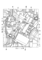
図1~図4を参照して内燃機関3及びその周辺構造について説明する。図2は図1のA-A線断面図であり、通路部材11の付近を上から見た図である。図3は図2のB-B線断面図、図4は図2のC-C線断面図である。<Internal combustion engine and peripheral structure>
The
内燃機関3は、SOHC型2バルブの単気筒4ストローク内燃機関であり、上から順に、ヘッドカバー31、シリンダヘッド32、シリンダブロック33及びクランクケース34を備える。内燃機関3は前傾されて車体フレーム2に支持されており、シリンダ軸線L1は上下方向に対して前側に傾斜している。線L1はシリンダ軸線を示し、シリンダブロック33のシリンダボア33aの中心軸線方向を示す。シリンダボア33a内のピストン33bがシリンダ軸線L1方向に往復運動し、クランク軸34aを回転させる。クランク軸34aは左右方向(車幅方向)を指向している。
The
シリンダヘッド32は、燃焼室320と、燃焼室320に連通した吸気ポート321及び排気ポート322を含む。吸気ポート321はシリンダヘッド32の後側に開口し、排気ポート322はシリンダヘッド32の前側に開口している。吸気ポート321、排気ポート322は、動弁機構333で駆動される吸気バルブ及び排気バルブ(いずれも図示省略)によって開閉される。
The
内燃機関3の排気構造15は、シリンダヘッド32に接続された排気管15aを含む。排気管15aはシリンダヘッド32の排気ポート322と連通する排気通路を形成し、燃焼ガスが排気管15aを介して排出される。
The
内燃機関3の吸気構造10は、シリンダヘッド32に接続された通路部材11、通路部材11に接続されたスロットル12、スロットル12とエアクリーナボックス14とを接続する接続管13とを含む。エアクリーナボックス14にはエアクリーナが配置されている。接続管13は、エアクリーナボックス14からメインフレーム21の側方を通って車両1の前側へ延設されており、かつ、車両1の右側に屈曲している(図2参照)。エアクリーナで浄化された空気は、接続管13、スロットル12及び通路部材11の各吸気通路を通ってシリンダヘッド32の吸気ポート321に導入される。シリンダヘッド32は通路部材11がガスケットを介して接続される接続面32aを有し、吸気ポート321は接続面32aに開口している。
The
通路部材11には取付ボス113が設けられ、取付ボス113にはインジェクタ16が取り付けられている。インジェクタ16は燃料タンク8に収容された燃料を吸気ポート321内に噴射する。取付ボス113は、インジェクタ16の先端側が挿入される穴113aを有する。図3における線L2は、穴113aの軸線方向を示しており、インジェクタ16の燃料噴射方向を示している。
A mounting
本実施形態の場合、吸気ポート321は、上下に区画された上側通路321a及び下側通路321bと、これらの合流通路321cとを含む。上側通路321a及び下側通路321bは、その上流側で接続面32aに開口し、その下流側で合流して合流通路321cを形成する。合流通路321cは燃焼室320に連通している。吸気ポート321の通路を上下に区画することで、燃焼室320内にタンブルを発生させることができる。
In the case of this embodiment, the
インジェクタ16の燃料噴射口は上側通路321aに臨み、線L2は合流通路321cを通過している。インジェクタ16から噴射される燃料が合流通路321cに向かい易くなり、上側通路321a及び下側通路321bの各通路を通った空気と燃料との混合を促進することができる。
The fuel injection port of the
<通路部材>
図5~図8を参照して通路部材11の構成について説明する。図5は通路部材11の平面図であり、より正確に言えば、線L1方向でヘッドカバー31の側から見た図である。図6は通路部材11をガスケットを介してシリンダヘッド32と接続される接続面111aの側から見た図である。図7は通路部材11をスロットル12と接続される接続面112aの側から見た図である。図8は図6のD-D線断面図である。<Passage material>
The structure of the
通路部材11は、筒状の管部110と、管部110の一端のフランジ部111と、管部110の他端のフランジ部112とを一体に備える。フランジ部111の端面は、ガスケットを介してシリンダヘッド32の接続面32aに接続される接続面111aである。フランジ部112の端面は、スロットル12に接続される接続面112aである。
The
通路部材11は、接続面112aから接続面111aに渡って形成された上側吸気通路11aと、下側吸気通路11bとを含む。上側吸気通路11aと下側吸気通路11bとは壁部11cで区画されている。上側吸気通路11aと下側吸気通路11bは、接続面111aにおいては互いに区画されて開口し、上側吸気通路11aは吸気ポート321の上側通路321aと連通し、下側吸気通路11bは吸気ポート321の下側通路321bと連通している。一方、上側吸気通路11aと下側吸気通路11bは上流側では合流し、接続面112aでは一つの開口を形成してスロットル12と連通している。
The
なお、本実施形態の複数の通路(11a及び321aの通路と、11b及び321bの通路)を持つ吸気構造は、個別に制御弁を持たず、共通のスロットル12にて吸気を制御する構造である。
The intake structure having a plurality of passages (
管部110はフランジ部111の側では線L1と直交する方向に直線的に延設され、フランジ部112の側では屈曲部110aにおいて平面視で左側に通路方向が屈曲されている。管部110を屈曲させることで、車両1の前後方向の長さを短くしつつ、上側吸気通路11a、下側吸気通路11bの通路長をより長く確保したり、或いは、周辺部品のレイアウト性を向上する。図5及び図8において、矢印BDは屈曲部110aの屈曲の内外方向を示しており、外側がOUT、内側がINで示されている。管部110の周面のうち、内側部分110b、外側部分110cは、内外方向BDで内側の部分と外側の部分に相当する。本実施形態では、屈曲部110aは車幅方向左側に屈曲しているため、車両1の車幅方向で屈曲部110aの内側110bが左側に、外側110cが右側に位置している。
The
取付ボス113はフランジ部111に一体に形成され、その一部が管部110に及んでいて、フランジ部111及び管部110から外側に(線L2方向に)突出している。取付ボス113は、穴113aを形成する筒状の部分であり、穴113aは上側吸気通路11aに連通している。筒状の取付ボス113は、その外周縁が接続面111aに接するほど、接続面111aに近接して配置されている。これにより、インジェクタ16を燃焼室320により近い位置に配置でき、燃料を燃焼室320により近い位置に噴射することができる。穴113aの軸線方向である線L2は上側吸気通路11aの中心線CTからオフセットした位置を通過しており、線L2が吸気ポート321のより深い位置(つまり、合流部321c)を指向するように、穴113aが形成されている。これも、インジェクタ16から燃料を燃焼室320により近い位置に噴射することに寄与する。
The mounting
フランジ部111には、上側吸気通路11a挟んで互いに反対側に締結部111b(本実施形態の場合、ボルト用の穴)が形成されており、締結部111bによってシリンダヘッド32に固定される。
Fastening
主に図5、図6、を参照して、取付ボス113の、上側吸気通路11aの径方向の位置や突出方向(線L2方向)について説明する。
Mainly referring to FIGS. 5 and 6, the position of the mounting
取付ボス113は、中心線CTに対して径方向にオフセットした位置に配置されている。また、突出方向(線L2方向)は、線L1’と交差する方向である。線L1’は中心線CTを通り、線L1と平行な線であり、シリンダ軸線方向を示している。従来例では、インジェクタの取付ボスは、接続面111a側から見ると図5の線L1’上に配置され、突出方向もシリンダ軸線方向とされる。本実施形態のように、取付ボス113を中心線CTに対して径方向にオフセットし、突出方向をシリンダ軸線方向と交差させることで、その上方(線L1の方向)への突出高さHを低くすることができる。参考として図6には、同様の取付ボスを線CL上に形成した場合の予想突出高さH’が図示されている。突出高さH’は突出高さHよりも突出量が大きい。
The mounting
本実施形態の構成により取付ボス113の突出量を抑えることで、ヘッドカバー31やシリンダヘッド32との干渉を回避しつつ、取付ボス113をシリンダヘッド32に近い位置に配置できる。つまり、インジェクタ16をシリンダヘッド32の燃焼室320により近い位置に配置でき、燃料を燃焼室320により近い位置に噴射することができる。
By suppressing the amount of protrusion of the mounting
取付ボス113の突出量を抑える点では、取付ボス113を中心線CTに対してオフセットする方向はどちらでも構わない。しかし、本実施形態の場合、通路部材11は屈曲部110aにおいて屈曲している。図5、図8に示すように、通路部材11の周囲の空間のうち、屈曲部110aの内側110bが左側に隣接する空間S2は、外側110cに隣接する空間S1よりも狭い。そこで本実施形態では、屈曲部110aの屈曲の内外方向で内側(IN)よりも外側(OUT)に偏った位置に取付ボス113を配置している。これにより、取付ボス113に取り付けられるインジェクタ16が、より広い空間S1の側に位置することになり、取付ボス113の周辺における他部品の配置の制約を少なくすることができる。
In terms of suppressing the amount of protrusion of the mounting
<通路部材の周辺の構造>
通路部材11の周辺の構造について図2~図4、図9及び図10を参照して説明する。図9は図4のE-E線断面図であり、図10は図4のF-F線断面図である。本実施形態のスロットル12は車両1の車幅方向で中心近傍に配置されている。これにより、スロットル12の車幅方向の突出を抑えることができる。<Structure around passage member>
The structure around the
本実施形態のスロットル12は、バルブボディ部120と、ドラム部121とを含む。図9及び図10はドラム部121が、そのケース部分を透過した透過図で示されている。ドラム121部は、スロットルグリップ5aに不図示のワイヤを介して連結され、スロットルグリップ5aの操作により回動するドラム121aを含む。バルブボディ部120は、ドラム121aと同軸上に設けられ、ドラム121aの回動により、吸気量を制御するバタフライ式のスロットルバルブ120aが設けられている。
The
ドラム部121は、通路部材11の側方に配置されており、特に、屈曲部110aの外側110cではなく内側110bに隣接して配置されている。すなわち、ドラム部121は、通路部材11に対して屈曲部110aの屈曲の内外方向で内側(IN)に配置されており、図5、図8の領域S2に配置されている。領域S1よりも比較的狭い領域S2をドラム部121の配置スペースとして活用することができる。
The
インジェクタ16には、燃料配管(不図示)が接続される接続部16a(図2参照)が設けられている。インジェクタ16は、全体として、車両1の車幅方向中心よりも右側に配置される一方、接続部16aは車両1の車幅方向の中心方向を向いている。燃料配管の車幅方向の突出を抑えることができる。
The
図9を参照して、インジェクタ16を避けるために、ヘッドカバー31は避け部31aを有し、シリンダヘッド32は避け部32bを有する。避け部31a、避け部32bはいずれも、中心線CTと平行な方向で、通路部材11と反対側(つまり、車両1の前側)に凹んだ凹部である。
Referring to FIG. 9, in order to avoid the
避け部31aは、ヘッドカバー31の下部のうち、接続面32aに隣接し、かつ、シリンダヘッド32と重なる部分に形成されており、特に、シリンダヘッド32のデッキ面に当接する、ヘッドカバー31の周縁部下面を含む一定の範囲に形成されている。避け部32bは、シリンダヘッド32のデッキ面周辺において、避け部31aと同様の部位に上下に重なるように形成されており、接続面32aの上側の部位に形成されている。
The avoiding
このような避け部31a、32bを設けない構成も採用可能であるが、避け部31a、32bを形成することで、インジェクタ16を更に燃焼室320に近い位置に配置することが可能となる。
Although a configuration without such avoiding
<他の実施形態>
上記実施形態では、吸気ポート321が2つの吸気通路321a、321bを有し、これに対応して通路部材11が2つの吸気通路11a、11bを有する構成としたが、いずれも単一の吸気通路を有する構成であってもよい。
<Other embodiments>
In the above embodiment, the
以上、発明の実施形態について説明したが、発明は上記の実施形態に制限されるものではなく、発明の要旨の範囲内で、種々の変形・変更が可能である。 Although the embodiments of the invention have been described above, the invention is not limited to the above embodiments, and various modifications and changes are possible within the scope of the gist of the invention.
Claims (8)
前記通路部材(11)に設けられ、燃料を噴射するインジェクタ(16)が取り付けられる取付ボス(113)と、
を備え、鞍乗型車両(1)に搭載される内燃機関(3)の吸気構造(10)であって、
前記通路部材(11)は、
前記吸気通路(11a)の通路方向を、前記鞍乗型車両(1)の車幅方向に屈曲させる屈曲部(110a)と、
前記シリンダヘッド(32)に接続される接続面(111a)を有するフランジ部(111)と、を含み、
前記取付ボス(113)は、
前記屈曲部(110a)の屈曲の内外方向(BD)で、内側(IN)よりも外側(OUT)に偏った位置において前記フランジ部(111)に一体に形成され、かつ、
前記通路部材(11)を前記接続面(111a)の側から見た場合、シリンダ軸線方向(L1')に対して交差する方向(L2)に突出し、
前記シリンダヘッド(32)は、
前記通路部材(11)の前記接続面(111a)が接続される接続面(32a)と、
前記接続面(32a)に隣接した部位に形成され、前記インジェクタ(16)を避ける第一の避け部(32b)と、を含む、
ことを特徴とする内燃機関の吸気構造。 a passage member (11) connected between a cylinder head (32) provided with a head cover (31) and a throttle (12) to form an intake passage (11a);
a mounting boss (113) provided in the passage member (11) to which an injector (16) for injecting fuel is mounted;
An intake structure (10) for an internal combustion engine (3) mounted on a straddle-type vehicle (1), comprising:
The passage member (11) is
a bending portion (110a) that bends the passage direction of the intake passage (11a) in the vehicle width direction of the straddle-type vehicle (1);
a flange portion (111) having a connection surface (111a) connected to the cylinder head (32),
The mounting boss (113) is
formed integrally with the flange portion (111) at a position biased outward (OUT) from the inner side (IN) in the inward-outward direction (BD) of the bend of the bent portion (110a), and
When the passage member (11) is viewed from the connecting surface (111a) side, the passage member (11) protrudes in a direction (L2) intersecting with the cylinder axial direction (L1'),
The cylinder head (32) is
a connection surface (32a) to which the connection surface (111a) of the passage member (11) is connected;
a first avoidance portion (32b) formed adjacent to the connection surface (32a) and avoiding the injector (16);
An intake structure for an internal combustion engine, characterized by:
前記取付ボス(113)は、前記インジェクタ(16)が挿入され、該インジェクタの燃料噴射方向(L2)を規定する穴(113a)を有し、
前記穴(113a)の軸線方向(L2)は、前記吸気通路(11a)の中心線(CT)からオフセットしている、
ことを特徴とする内燃機関の吸気構造。 An intake structure for an internal combustion engine according to claim 1,
The mounting boss (113) has a hole (113a) into which the injector (16) is inserted and defines a fuel injection direction (L2) of the injector,
The axial direction (L2) of the hole (113a) is offset from the centerline (CT) of the intake passage (11a),
An intake structure for an internal combustion engine, characterized by:
前記スロットル(12)は、前記通路部材(11)の上流側の端部(112)に取り付けられ、
前記スロットル(12)のドラム部(121)は、前記屈曲部(110a)の屈曲の内外方向(BD)で、内側(IN)に位置している、
ことを特徴とする内燃機関の吸気構造。 An intake structure for an internal combustion engine according to claim 1 or claim 2,
The throttle (12) is attached to the upstream end (112) of the passage member (11),
The drum portion (121) of the throttle (12) is located inside (IN) of the bending of the bending portion (110a) in the lateral direction (BD),
An intake structure for an internal combustion engine, characterized by:
前記通路部材(11)は、
前記吸気通路である第一吸気通路(11a)と、
前記第一吸気通路とは別の第二吸気通路(11b)と、を形成し、
前記シリンダヘッド(32)の吸気ポート(321)は、
前記第一吸気通路(11a)と連通した第一通路(321a)と、
前記第二吸気通路(11b)と連通した第二通路(321b)と、
前記第一通路(321a)と前記第二通路(321b)とが下流側で合流した合流通路(321c)と、を含み、
前記穴(113a)の軸線方向(L2)は、前記合流通路(321c)を通過している、
ことを特徴とする内燃機関の吸気構造。 An intake structure for an internal combustion engine according to claim 2,
The passage member (11) is
a first intake passage (11a), which is the intake passage;
forming a second intake passage (11b) separate from the first intake passage;
The intake port (321) of the cylinder head (32) is
a first passageway (321a) communicating with the first intake passageway (11a);
a second passageway (321b) communicating with the second intake passageway (11b);
a confluence passageway (321c) in which the first passageway (321a) and the second passageway (321b) merge on the downstream side,
The axial direction (L2) of the hole (113a) passes through the joint passage (321c),
An intake structure for an internal combustion engine, characterized by:
前記ヘッドカバー(31)は、前記シリンダヘッド(32)の前記接続面(32a)に隣接し、かつ、前記シリンダヘッド(32)と重なる部分において、前記インジェクタ(16)を避ける第二の避け部(31a)を含む、
ことを特徴とする内燃機関の吸気構造。 An intake structure for an internal combustion engine according to any one of claims 1 to 4,
The head cover (31) is adjacent to the connection surface (32a) of the cylinder head (32) and overlaps with the cylinder head (32) as a second avoiding portion that avoids the injector (16). including (31a)
An intake structure for an internal combustion engine, characterized by:
前記インジェクタ(16)には、燃料配管が接続される接続部(16a)が設けられており、
前記接続部(16a)は、前記内外方向(BD)で、内側(IN)を向いている、
ことを特徴とする内燃機関の吸気構造。 An intake structure for an internal combustion engine according to any one of claims 1 to 5 ,
The injector (16) is provided with a connection portion (16a) to which a fuel pipe is connected,
The connecting portion (16a) faces inward (IN) in the medial-lateral direction (BD),
An intake structure for an internal combustion engine, characterized by:
前記穴(113a)の入口は、前記内外方向(BD)で前記中心線(CT)よりも外側(OUT)に位置している、
ことを特徴とする内燃機関の吸気構造。 An intake structure for an internal combustion engine according to claim 2,
The entrance of the hole (113a) is located outside (OUT) of the center line (CT) in the medial-lateral direction (BD),
An intake structure for an internal combustion engine, characterized by:
前記取付ボス(113)は、前記通路方向で、前記フランジ部(111)の幅内に形成されている、
ことを特徴とする内燃機関の吸気構造。 An intake structure for an internal combustion engine according to claim 1,
The mounting boss (113) is formed within the width of the flange portion (111) in the passage direction,
An intake structure for an internal combustion engine, characterized by:
Applications Claiming Priority (3)
| Application Number | Priority Date | Filing Date | Title |
|---|---|---|---|
| JP2019037741 | 2019-03-01 | ||
| JP2019037741 | 2019-03-01 | ||
| PCT/JP2020/008416 WO2020179694A1 (en) | 2019-03-01 | 2020-02-28 | Air intake structure for internal combustion engine |
Publications (2)
| Publication Number | Publication Date |
|---|---|
| JPWO2020179694A1 JPWO2020179694A1 (en) | 2020-09-10 |
| JP7229334B2 true JP7229334B2 (en) | 2023-02-27 |
Family
ID=72337778
Family Applications (1)
| Application Number | Title | Priority Date | Filing Date |
|---|---|---|---|
| JP2021504059A Active JP7229334B2 (en) | 2019-03-01 | 2020-02-28 | Intake structure of internal combustion engine |
Country Status (2)
| Country | Link |
|---|---|
| JP (1) | JP7229334B2 (en) |
| WO (1) | WO2020179694A1 (en) |
Citations (11)
| Publication number | Priority date | Publication date | Assignee | Title |
|---|---|---|---|---|
| JP2000145467A (en) | 1998-09-07 | 2000-05-26 | Yamaha Motor Co Ltd | Intake system for engine |
| JP2003097392A (en) | 2001-09-20 | 2003-04-03 | Yamaha Motor Co Ltd | Injector arrangement structure of fuel injection engine |
| JP2005307871A (en) | 2004-04-22 | 2005-11-04 | Honda Motor Co Ltd | Intake device for internal combustion engine for motorcycle |
| JP2006057566A (en) | 2004-08-23 | 2006-03-02 | Yamaha Motor Co Ltd | Vehicle |
| WO2006100849A1 (en) | 2005-03-18 | 2006-09-28 | Toyota Jidosha Kabushiki Kaisha | Dual-system fuel injection engine |
| JP2007262995A (en) | 2006-03-29 | 2007-10-11 | Denso Corp | Injector installing structure and fuel injector |
| JP2007285171A (en) | 2006-04-14 | 2007-11-01 | Denso Corp | Intake pipe mounting structure |
| JP2009103024A (en) | 2007-10-23 | 2009-05-14 | Honda Motor Co Ltd | Mounting structure of fuel injection valve |
| JP2012207611A (en) | 2011-03-30 | 2012-10-25 | Honda Motor Co Ltd | Internal combustion engine |
| JP2015190373A (en) | 2014-03-28 | 2015-11-02 | 本田技研工業株式会社 | Internal combustion engine intake structure |
| WO2017154782A1 (en) | 2016-03-09 | 2017-09-14 | 本田技研工業株式会社 | Internal combustion engine intake structure |
Family Cites Families (1)
| Publication number | Priority date | Publication date | Assignee | Title |
|---|---|---|---|---|
| JPH0373666U (en) * | 1989-11-21 | 1991-07-24 |
-
2020
- 2020-02-28 WO PCT/JP2020/008416 patent/WO2020179694A1/en active Application Filing
- 2020-02-28 JP JP2021504059A patent/JP7229334B2/en active Active
Patent Citations (11)
| Publication number | Priority date | Publication date | Assignee | Title |
|---|---|---|---|---|
| JP2000145467A (en) | 1998-09-07 | 2000-05-26 | Yamaha Motor Co Ltd | Intake system for engine |
| JP2003097392A (en) | 2001-09-20 | 2003-04-03 | Yamaha Motor Co Ltd | Injector arrangement structure of fuel injection engine |
| JP2005307871A (en) | 2004-04-22 | 2005-11-04 | Honda Motor Co Ltd | Intake device for internal combustion engine for motorcycle |
| JP2006057566A (en) | 2004-08-23 | 2006-03-02 | Yamaha Motor Co Ltd | Vehicle |
| WO2006100849A1 (en) | 2005-03-18 | 2006-09-28 | Toyota Jidosha Kabushiki Kaisha | Dual-system fuel injection engine |
| JP2007262995A (en) | 2006-03-29 | 2007-10-11 | Denso Corp | Injector installing structure and fuel injector |
| JP2007285171A (en) | 2006-04-14 | 2007-11-01 | Denso Corp | Intake pipe mounting structure |
| JP2009103024A (en) | 2007-10-23 | 2009-05-14 | Honda Motor Co Ltd | Mounting structure of fuel injection valve |
| JP2012207611A (en) | 2011-03-30 | 2012-10-25 | Honda Motor Co Ltd | Internal combustion engine |
| JP2015190373A (en) | 2014-03-28 | 2015-11-02 | 本田技研工業株式会社 | Internal combustion engine intake structure |
| WO2017154782A1 (en) | 2016-03-09 | 2017-09-14 | 本田技研工業株式会社 | Internal combustion engine intake structure |
Also Published As
| Publication number | Publication date |
|---|---|
| JPWO2020179694A1 (en) | 2020-09-10 |
| WO2020179694A1 (en) | 2020-09-10 |
Similar Documents
| Publication | Publication Date | Title |
|---|---|---|
| US7086364B2 (en) | Intake system for V-engine | |
| US8113168B2 (en) | Engine unit and vehicle including the same | |
| US8047179B2 (en) | Engine unit and vehicle including the same | |
| JP2009202827A (en) | Motorcycle | |
| JP4167635B2 (en) | Fuel supply device for V-type engine for vehicle | |
| JP2009150400A (en) | Motorcycle | |
| US10385804B2 (en) | Single cylinder internal combustion engine | |
| JP3153075U (en) | Vehicle engine unit and saddle-ride type vehicle | |
| US9518548B2 (en) | Fuel supply apparatus of internal combustion engine | |
| JP7229334B2 (en) | Intake structure of internal combustion engine | |
| US8042521B2 (en) | Engine unit and vehicle provided with the same | |
| JP2020079597A (en) | Internal combustion engine | |
| JP4250141B2 (en) | Motorcycle | |
| JP5481283B2 (en) | Cylinder head structure of internal combustion engine | |
| JP6865078B2 (en) | Internal combustion engine cylinder head | |
| JP6003488B2 (en) | Intake device for motorcycle | |
| JP2011256836A (en) | Cylinder head structure of internal combustion engine | |
| JP6322909B2 (en) | Fuel supply device for internal combustion engine | |
| JP2011190759A (en) | Wiring structure to throttle body in compact vehicle | |
| JP2015178815A (en) | Saddle riding type vehicle | |
| JP6495060B2 (en) | In-cylinder internal combustion engine | |
| JP2019135129A (en) | Intake device for saddle-riding type vehicle | |
| JP6875439B2 (en) | Fuel injection device layout structure | |
| JP5720675B2 (en) | Engine fuel injector | |
| JP2010228735A (en) | Motorcycle |
Legal Events
| Date | Code | Title | Description |
|---|---|---|---|
| A521 | Request for written amendment filed |
Free format text: JAPANESE INTERMEDIATE CODE: A523 Effective date: 20210817 |
|
| A529 | Written submission of copy of amendment under article 34 pct |
Free format text: JAPANESE INTERMEDIATE CODE: A5211 Effective date: 20210817 |
|
| A621 | Written request for application examination |
Free format text: JAPANESE INTERMEDIATE CODE: A621 Effective date: 20210817 |
|
| A131 | Notification of reasons for refusal |
Free format text: JAPANESE INTERMEDIATE CODE: A131 Effective date: 20221011 |
|
| A521 | Request for written amendment filed |
Free format text: JAPANESE INTERMEDIATE CODE: A523 Effective date: 20221209 |
|
| TRDD | Decision of grant or rejection written | ||
| A01 | Written decision to grant a patent or to grant a registration (utility model) |
Free format text: JAPANESE INTERMEDIATE CODE: A01 Effective date: 20230127 |
|
| A61 | First payment of annual fees (during grant procedure) |
Free format text: JAPANESE INTERMEDIATE CODE: A61 Effective date: 20230214 |
|
| R150 | Certificate of patent or registration of utility model |
Ref document number: 7229334 Country of ref document: JP Free format text: JAPANESE INTERMEDIATE CODE: R150 |