JP5995775B2 - Resin cover mounting structure - Google Patents

Resin cover mounting structure Download PDF

Info

Publication number
JP5995775B2
JP5995775B2 JP2013094669A JP2013094669A JP5995775B2 JP 5995775 B2 JP5995775 B2 JP 5995775B2 JP 2013094669 A JP2013094669 A JP 2013094669A JP 2013094669 A JP2013094669 A JP 2013094669A JP 5995775 B2 JP5995775 B2 JP 5995775B2
Authority
JP
Japan
Prior art keywords
resin cover
coupled
cover
gasket
head
Prior art date
Legal status (The legal status is an assumption and is not a legal conclusion. Google has not performed a legal analysis and makes no representation as to the accuracy of the status listed.)
Active
Application number
JP2013094669A
Other languages
Japanese (ja)
Other versions
JP2014214717A (en
Inventor
加代子 武市
加代子 武市
政秀 味村
政秀 味村
修一 落合
修一 落合
詠介 梶原
詠介 梶原
靖彦 中野
靖彦 中野
遼太 高橋
遼太 高橋
杉生 大輔
大輔 杉生
保男 寺田
保男 寺田
英之 稲葉
英之 稲葉
定彦 山口
定彦 山口
雅弘 家永
雅弘 家永
Current Assignee (The listed assignees may be inaccurate. Google has not performed a legal analysis and makes no representation or warranty as to the accuracy of the list.)
Honda Motor Co Ltd
Asahi Kasei Corp
Original Assignee
Honda Motor Co Ltd
Asahi Kasei Corp
Priority date (The priority date is an assumption and is not a legal conclusion. Google has not performed a legal analysis and makes no representation as to the accuracy of the date listed.)
Filing date
Publication date
Application filed by Honda Motor Co Ltd, Asahi Kasei Corp filed Critical Honda Motor Co Ltd
Priority to JP2013094669A priority Critical patent/JP5995775B2/en
Priority to IN2054CH2014 priority patent/IN2014CH02054A/en
Publication of JP2014214717A publication Critical patent/JP2014214717A/en
Application granted granted Critical
Publication of JP5995775B2 publication Critical patent/JP5995775B2/en
Active legal-status Critical Current
Anticipated expiration legal-status Critical

Links

Images

Description

本発明は、樹脂製カバーの取付構造に関する。   The present invention relates to a resin cover mounting structure.

従来の樹脂製カバーとして、例えば、軽量化やコスト低減を図るべく樹脂を採用した、内燃機関のヘッドカバー等がある(特許文献1参照)。特許文献1に開示される構成では、樹脂製カバーであるヘッドカバーがボルトを介して被結合部材であるシリンダヘッドに締結されるとともに、シリンダヘッドとヘッドカバーとの結合面に、ガスケットが挟持されている。ガスケットは、結合面全体に渡って延びる枠状部分と、前記ボルトの締結孔周りに位置するフランジ状部分とを含む形状に形成されている。   As a conventional resin cover, for example, there is a head cover of an internal combustion engine that employs a resin for weight reduction and cost reduction (see Patent Document 1). In the configuration disclosed in Patent Document 1, a head cover that is a resin cover is fastened to a cylinder head that is a member to be coupled via a bolt, and a gasket is sandwiched between coupling surfaces of the cylinder head and the head cover. . The gasket is formed in a shape including a frame-like portion extending over the entire coupling surface and a flange-like portion positioned around the fastening hole of the bolt.

実開平7−10450号公報Japanese Utility Model Publication No. 7-10450

しかしながら、上記特許文献1に開示の構成のように、剛性を確保しにくい樹脂製のヘッドカバーをボルト等の締結部材にてシリンダヘッドに締結固定する場合には、ヘッドカバーとシリンダヘッドとの間にガスケットが挟持されることから、ヘッドカバーはガスケットの反力を受け、この反力によって樹脂製のヘッドカバーに撓みや変形が生じやすいという課題がある。詳しくは、ガスケットを挟圧する挟圧力が、締結孔に近接した部位では大きくなるため、締結孔に近接した部位ではヘッドカバーとシリンダヘッドとが近づく方向へ向けて撓みや変形を起こしやすくなる一方、締結孔から離れた部位ではガスケットの挟圧力が小さくなるため、上記近接した部位におけるガスケットの反力の影響を受けてヘッドカバーとシリンダヘッドとが離間する方向へ向けて撓みや変形を起こしやすくなる。そして、このような撓みや変形が生じると、ヘッドカバーの部位毎でシール性のバラつきが生じやすくなってしまう場合がある。   However, when the resin head cover, which is difficult to ensure rigidity, is fastened to the cylinder head with a fastening member such as a bolt as in the configuration disclosed in Patent Document 1, a gasket is provided between the head cover and the cylinder head. Therefore, there is a problem that the head cover receives a reaction force of the gasket, and the reaction force tends to cause the resin head cover to bend or deform. Specifically, since the clamping pressure for clamping the gasket is large at the part close to the fastening hole, the head cover and the cylinder head are likely to bend and deform in the direction approaching the fastening hole while fastening. Since the gasket clamping pressure is reduced at the part away from the hole, the head cover and the cylinder head are likely to bend and deform in the direction away from each other due to the influence of the reaction force of the gasket at the adjacent part. And when such a bending and a deformation | transformation arise, it may become easy to produce the sealing property variation for every site | part of a head cover.

したがって、上記樹脂製のヘッドカバーのような樹脂製カバーをガスケットを介して被結合部材に取付固定するに際しては、樹脂製カバーの撓みや変形を抑えて、被結合部分との間に安定したシール性を確保することが望まれる。このように安定したシール性を確保することは、特許文献1に開示されるような内燃機関の樹脂製のヘッドカバーに限らず、類似する構成の一般的な樹脂製カバー全般に望まれるものである。   Therefore, when mounting and fixing a resin cover such as the resin head cover to a member to be coupled via a gasket, the resin cover can be prevented from being bent or deformed, and a stable sealing property can be provided between the resin cover. It is desirable to ensure. Ensuring such a stable sealing property is desired not only for resin-made head covers of internal combustion engines as disclosed in Patent Document 1, but also for general resin-covers having a similar configuration in general. .

本発明は上述の実情に鑑みてなされたものであり、樹脂製カバーを被結合部材に取付けた際に、樹脂製カバーの撓みや変形が抑えられ、樹脂製カバーと被結合部材との結合部分に安定したシール性を確保できる樹脂製カバーの取付構造を提供することを目的とする。   The present invention has been made in view of the above circumstances, and when a resin cover is attached to a member to be coupled, bending and deformation of the resin cover are suppressed, and a coupling portion between the resin cover and the member to be coupled is provided. It is an object of the present invention to provide a resin cover mounting structure that can secure a stable sealing property.

上記課題の解決手段として、請求項1に記載の発明は、樹脂製カバー(25)と該樹脂製カバー(25)の被結合部材(24)とが締結部材(50)によって結合されて内部に空間が形成され、前記樹脂製カバー(25)及び前記被結合部材(24)には、前記空間を囲んで結合される前記樹脂製カバー(25)と前記被結合部材(24)との結合面(36,37)と、前記結合面(36,37)から、前記空間の外方に向けて膨出するとともに、前記締結部材(50)によって締結されるフランジ部(48,45)がそれぞれ形成され、前記結合面(36,37)及び前記フランジ部(48,45)に渡ってガスケット(40)が挟持される樹脂製カバーの取付構造において、前記樹脂製カバー(25)及び前記被結合部材(24)それぞれの前記フランジ部(48,45)に対向する、弾性変形可能な前記ガスケット(40)におけるフランジ当接部(42)には、前記締結部材(50)を貫通させる貫通穴(51)が形成され、前記フランジ当接部(42)には、前記貫通穴(51)の軸方向に沿う厚み寸法が、前記空間側よりも前記フランジ部(48,45)の膨出端部(48A,45A)側の方が大きくなるように厚肉部(70)が形成され、前記フランジ当接部(42)から前記樹脂製カバー(25)の外周壁、又は、前記被結合部材(24)の外周壁に沿って、前記貫通穴(51)の軸方向に延出するとともに、前記樹脂製カバー(25)の外周壁、又は、前記被結合部材(24)の外周壁に密着する保持壁部(72)が、前記厚肉部(70)から延出して前記フランジ当接部(42)に一体に形成されることを特徴とする。 As a means for solving the above problem, the invention according to claim 1 is characterized in that the resin cover (25) and the member to be coupled (24) of the resin cover (25) are coupled to each other by the fastening member (50). A space is formed, and the resin cover (25) and the member to be coupled (24) are coupled to the resin cover (25) and the member to be coupled (24) to be coupled to surround the space. (36, 37) and flange portions (48, 45) that bulge outward from the space and are fastened by the fastening member (50) from the coupling surfaces (36, 37), respectively. In the resin cover mounting structure in which the gasket (40) is sandwiched across the coupling surfaces (36, 37) and the flange portions (48, 45), the resin cover (25) and the coupled member (24) That Facing the flange portion of the (48,45), the flange abutment (42) in an elastically deformable wherein said gasket (40), through holes for passing the fastening member (50) (51) is formed The flange abutting portion (42) has a thickness dimension along the axial direction of the through hole (51), and the bulging end portion (48A, 45A) of the flange portion (48, 45) rather than the space side. A thick portion (70) is formed so that the side is larger, and the outer peripheral wall of the resin cover (25) from the flange contact portion (42) or the outer peripheral wall of the coupled member (24) A holding wall (72) that extends in the axial direction of the through hole (51) along the outer periphery of the resin cover (25) or closely contacts the outer peripheral wall of the member to be coupled (24). ) Extends from the thick wall portion (70) and Characterized in that it is formed integrally with the di abutment (42).

請求項2に記載の発明は、前記フランジ当接部(42)には、前記貫通穴(51)の周囲に形成される前記厚肉部(70)と、該厚肉部(70)よりも薄い非厚肉部(71)とが含まれており、前記締結部材(50)による締結時に、前記樹脂製カバー(25)と前記被結合部材(24)とで挟圧されて圧縮される前記フランジ当接部(42)における圧縮量が、前記非厚肉部(71)よりも前記厚肉部(70)の方が大きくなるように構成されることを特徴とする。   According to a second aspect of the present invention, the flange abutting portion (42) includes the thick portion (70) formed around the through hole (51) and the thick portion (70). A thin non-thick portion (71) is included, and when being fastened by the fastening member (50), the resin cover (25) and the coupled member (24) are sandwiched and compressed. The compression amount in the flange contact portion (42) is configured such that the thick portion (70) is larger than the non-thick portion (71).

請求項3に記載の発明は、前記締結部材(50)は段付きボルトであって、該締結部材(50)の前記樹脂製カバー(25)側又は前記被結合部材(24)側を向く段差面(50E)は、前記貫通穴(51)を貫通して前記樹脂製カバー(25)又は前記被結合部材(24)に当接し、前記樹脂製カバー(25)は、前記被結合部材(50)に前記ガスケット(40)を介してフローティング支持されることを特徴とする。   According to a third aspect of the present invention, the fastening member (50) is a stepped bolt, and the step facing the resin cover (25) side or the coupled member (24) side of the fastening member (50). The surface (50E) penetrates the through hole (51) and comes into contact with the resin cover (25) or the coupled member (24), and the resin cover (25) is coupled to the coupled member (50). ) Is supported floating through the gasket (40).

請求項4に記載の発明は、前記ガスケット(40)には、前記貫通穴(51)を挟んで前記保持壁部(72)と対向する位置に、前記樹脂製カバー(25)又は前記被結合部材(24)に対する係合部(74)が形成され、前記保持壁部(72)と、前記係合部(74)と、前記貫通穴(51)の中心軸線(L4)とが、前記貫通穴(51)の軸方向視で同一直線状に配置されることを特徴とする。 According to a fourth aspect of the present invention, in the gasket (40), the resin cover (25) or the coupled member is disposed at a position facing the holding wall (72) across the through hole (51). An engagement portion (74) for the member (24) is formed, and the holding wall portion (72), the engagement portion (74), and a central axis (L4) of the through hole (51) are formed through the penetration. The holes (51) are arranged in the same straight line as viewed in the axial direction .

請求項5に記載の発明は、前記保持壁部(72)には、前記樹脂製カバー(25)の外周壁、又は、前記被結合部材(24)の外周壁に設けられた第1の被係合部(80)に対して係合可能な第1の係合部(73)が形成されることを特徴とする。 According to a fifth aspect of the present invention, in the holding wall portion (72), a first covered member provided on the outer peripheral wall of the resin cover (25) or the outer peripheral wall of the coupled member (24). A first engaging portion (73) that can be engaged with the engaging portion (80) is formed.

請求項6に記載の発明は、前記第1の係合部(73)は、前記保持壁部(72)において、前記樹脂製カバー(25)及び前記被結合部材(24)それぞれの前記フランジ部(48,45)の前記膨出端部(48A,45A)側に位置する部位に形成されることを特徴とする。 According to a sixth aspect of the present invention, the first engaging portion (73) includes the flange portion of each of the resin cover (25) and the coupled member (24) in the holding wall portion (72). It is formed in the site | part located in the said bulging end part (48A, 45A) side of (48, 45).

請求項7に記載の発明は、前記ガスケット(40)には、前記貫通穴(51)を挟んで前記第1の係合部(73)と対向する位置に、第2の係合部(74)が形成され、前記第2の係合部(74)が係合可能な第2の被係合部(81)が、前記樹脂製カバー(25)又は前記被結合部材(24)に形成されることを特徴とする。 According to a seventh aspect of the present invention, in the gasket (40), the second engagement portion (74) is located at a position facing the first engagement portion (73) across the through hole (51). ) And a second engaged portion (81) with which the second engaging portion (74) can be engaged is formed on the resin cover (25) or the coupled member (24). It is characterized by that.

請求項1に記載の発明によれば、樹脂製カバーと被結合部材とがガスケットを挟持して、互いのフランジ部で締結固定される際は、締結に伴って樹脂製カバーにおける締結部材周りの特に外方側、すなわちフランジ部の膨出端部側が、被結合部材に近づく方向へ向けて特に撓みや変形を起こしやすくなるが、ガスケットにおける上記フランジ部に対向するフランジ当接部には、締結部材が貫通する貫通穴の軸方向に沿う厚み寸法が、空間側よりもフランジ部の膨出端部側の方が大きくなるように、厚肉部を形成したので、締結部材周りの特に外方側、すなわちフランジ部における膨出端部側のガスケットの反力を高めて、樹脂製カバーが被結合部材に近づく方向へ向けて撓もうとするのを抑制することができる。さらに、締結部材周りでの樹脂製カバーの撓みや変形を抑制することで、締結部材から離れた樹脂製カバーにおける部位の撓みや変形も合わせて抑制することができる。これにより、本発明では、樹脂製カバーと被結合部材との結合部分に安定したシール性を確保することができる。
また、ガスケットを樹脂製カバー又は被結合部材に保持させた状態で、樹脂製カバーと被結合部材とを組み付けることができる。また、樹脂製カバーと被結合部材との組み付けの際、保持壁部が、樹脂製カバー部の外周壁、又は、被結合部材の外周壁に密着するので、ガスケットにおけるフランジ当接部を安定して樹脂製カバー又は被結合部材のフランジ部周りの所定の位置に位置決めさせておくことができ、締結部材による締結作業も容易に行うことができる。
また、保持壁部の剛性、及び樹脂製カバー又は被結合部材への保持力を効果的に高めることができる。
According to the first aspect of the present invention, when the resin cover and the member to be joined sandwich the gasket and are fastened and fixed by the flange portions of the resin cover, the periphery of the fastening member in the resin cover is accompanied by fastening. In particular, the outward side, that is, the bulging end side of the flange portion, is particularly likely to bend and deform in the direction approaching the member to be coupled, but the flange contact portion facing the flange portion of the gasket is fastened. The thick part is formed so that the thickness dimension along the axial direction of the through-hole through which the member penetrates is larger on the bulging end side of the flange part than on the space side. The reaction force of the gasket on the side, that is, the bulging end side of the flange portion, can be increased, and the resin cover can be prevented from bending toward the direction to be coupled. Furthermore, the bending and deformation | transformation of the site | part in the resin cover away from the fastening member can also be suppressed by suppressing the bending and deformation | transformation of the resin cover around a fastening member. Thereby, in this invention, the stable sealing performance can be ensured in the coupling | bond part of resin-made covers and to-be-joined members.
Further, the resin cover and the member to be coupled can be assembled in a state where the gasket is held by the resin cover or the member to be coupled. Further, when the resin cover and the member to be coupled are assembled, the holding wall portion is in close contact with the outer peripheral wall of the resin cover portion or the outer peripheral wall of the member to be coupled, so that the flange contact portion of the gasket is stabilized. Thus, it can be positioned at a predetermined position around the flange portion of the resin cover or the member to be coupled, and the fastening work by the fastening member can be easily performed.
Further, the rigidity of the holding wall portion and the holding force to the resin cover or the coupled member can be effectively increased.

請求項2に記載の発明によれば、厚肉部の圧縮量を非厚肉部の圧縮量よりも大きくすることで、厚肉部における締結に伴うガスケットの反力を確実に大きくすることができ、効果的に樹脂製カバーの撓みや変形を抑制することができる。   According to the invention described in claim 2, by making the compression amount of the thick portion larger than the compression amount of the non-thick portion, the reaction force of the gasket accompanying fastening at the thick portion can be reliably increased. It is possible to effectively suppress the bending and deformation of the resin cover.

請求項3に記載の発明によれば、段付きボルトによって締結量を規定することができ、締めすぎを防止して厚肉部の反力を好適に樹脂製カバーに加えることができ、樹脂製カバーの撓みや変形を好適に抑制することができる。さらに、樹脂製カバーが、被結合部材にガスケットを介してフローティング支持されるため、被結合部材から樹脂製カバーへの熱伝導や振動等の伝達を低減することができる。   According to the third aspect of the present invention, the fastening amount can be defined by the stepped bolt, the excessive force can be prevented, and the reaction force of the thick portion can be suitably applied to the resin cover. Bending and deformation of the cover can be suitably suppressed. Further, since the resin cover is floatingly supported by the coupled member via the gasket, it is possible to reduce transmission of heat conduction, vibration, and the like from the coupled member to the resin cover.

請求項5に記載の発明によれば、一層効果的にガスケットにおけるフランジ当接部の位置ずれを防止することができ、樹脂製カバーと被結合部材との組み付け性を向上することができる。 According to the fifth aspect of the present invention, it is possible to more effectively prevent the flange abutting portion of the gasket from being displaced and to improve the assembling property between the resin cover and the member to be coupled.

請求項6に記載の発明によれば、第1の係合部が膨出端部側から係合することによって、保持壁部による保持効果が一層高まり、ガスケットを樹脂製カバー又は被結合部材に一層効果的に保持させることができる。 According to the sixth aspect of the present invention, when the first engaging portion is engaged from the bulging end portion side, the holding effect by the holding wall portion is further enhanced, and the gasket is used as the resin cover or the coupled member. It can be held more effectively.

請求項7に記載の発明によれば、貫通穴を挟み込むようにして、保持壁部の第1の係合部と、第2の係合部とが対向して設けられるので、締結部材による締結時に、ガスケットの位置ずれを一層効果的に防止することができる。また、締結時に、締結部材の回転に伴ってガスケットが連れまわりにくくなり、位置決めを効果的に行えるようになる。
According to the seventh aspect of the present invention, since the first engagement portion and the second engagement portion of the holding wall portion are provided to face each other so as to sandwich the through hole, the fastening by the fastening member is performed. Sometimes, the displacement of the gasket can be more effectively prevented. Further, at the time of fastening, it becomes difficult for the gasket to be carried along with the rotation of the fastening member, and positioning can be performed effectively.

本発明の実施形態に係る構造が適用された自動二輪車の左側面図である。1 is a left side view of a motorcycle to which a structure according to an embodiment of the present invention is applied. 上記自動二輪車の内燃機関周辺の左側面図である。Fig. 2 is a left side view around the internal combustion engine of the motorcycle. 上記自動二輪車の内燃機関周辺の上面図である。FIG. 2 is a top view around the internal combustion engine of the motorcycle. 上記内燃機関のシリンダ部の左側面図である。It is a left view of the cylinder part of the said internal combustion engine. 上記内燃機関のシリンダ部をシリンダ軸線に沿って前方側から見た図である。It is the figure which looked at the cylinder part of the said internal combustion engine from the front side along the cylinder axis. 上記内燃機関のシリンダ部の斜視図である。It is a perspective view of the cylinder part of the said internal combustion engine. 上記内燃機関のシリンダ部を構成するヘッドカバーの内部を、シリンダ軸線に沿って見た図であり、ガスケットがヘッドカバーに保持された状態の図である。It is the figure which looked at the inside of the head cover which comprises the cylinder part of the said internal combustion engine along the cylinder axis line, and is a figure of the state by which the gasket was hold | maintained at the head cover. 上記内燃機関のシリンダ部を構成するシリンダヘッドの内部を、シリンダ軸線に沿って見た図である。It is the figure which looked at the inside of the cylinder head which comprises the cylinder part of the said internal combustion engine along the cylinder axis. 上記シリンダヘッドの斜視図である。It is a perspective view of the cylinder head. 上記ヘッドカバーの内部を、シリンダ軸線に沿って見た図である。It is the figure which looked at the inside of the above-mentioned head cover along the cylinder axis. シリンダヘッドとヘッドカバーとの間に挟持されるガスケットを示した図である。It is the figure which showed the gasket clamped between a cylinder head and a head cover. 上記ガスケットの斜視図である。It is a perspective view of the said gasket. 上記ガスケットの要部の拡大斜視図の拡大図である。It is an enlarged view of the enlarged perspective view of the principal part of the said gasket. ガスケットをヘッドカバーに保持した状態を、図11のA−A線に対応する断面で示した断面図であり、ヘッドカバーとシリンダヘッドとの組み付けを説明する図である。FIG. 12 is a cross-sectional view showing a state in which the gasket is held on the head cover, in a cross section corresponding to the line AA in FIG. ヘッドカバーにガスケットを保持した状態で、シリンダヘッドに組み付ける際の、組み付け初期の状態を、図11のA−A線に対応する断面で示した断面図であり、ヘッドカバーとシリンダヘッドとの組み付けを説明する図である。FIG. 12 is a cross-sectional view showing an initial state of assembly when assembling to the cylinder head with the gasket held on the head cover, in a cross section corresponding to the line AA in FIG. 11, and explaining the assembly of the head cover and the cylinder head. It is a figure to do. 図15に示した状態から、ボルトの締結を進めた状態を、図11のA−A線に対応する断面で示した断面図であり、ヘッドカバーとシリンダヘッドとの組み付けを説明する図である。FIG. 16 is a cross-sectional view showing a state in which the bolt has been fastened from the state shown in FIG. 15 in a cross section corresponding to the line AA in FIG. 11, and is a view for explaining the assembly of the head cover and the cylinder head. 図16に示した状態から、ボルトの締結を進めた組み付け完了状態を、図11のA−A線に対応する断面で示した断面図である。It is sectional drawing which showed the assembly completion state which advanced the fastening of the bolt from the state shown in FIG. 16 in the cross section corresponding to the AA line of FIG.

以下、本発明の実施形態を図面に基づいて説明する。なお、以下で用いる図面において、矢印FRは車両の前方を示し、矢印UPは車両の上方を示し、矢印LHは車両の左方を示している。以下で説明する実施形態は、本発明の樹脂製カバーの取付構造を鞍乗型車両に搭載された内燃機関のシリンダヘッドとヘッドカバーに適用したものである。   Hereinafter, embodiments of the present invention will be described with reference to the drawings. In the drawings used below, arrow FR indicates the front of the vehicle, arrow UP indicates the upper side of the vehicle, and arrow LH indicates the left side of the vehicle. In the embodiment described below, the resin cover mounting structure of the present invention is applied to a cylinder head and a head cover of an internal combustion engine mounted on a straddle-type vehicle.

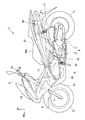
図1は、本発明が適用された内燃機関を備えるスクータ型の自動二輪車1を示している。まず、自動二輪車1の構成について説明する。この自動二輪車1は、内燃機関2と動力伝達機構3とを一体としたスイングユニット4を備え、スイングユニット4の後部で後輪5を回動可能に支持するとともに、スイングユニット4の前方に、操舵系を構成する前輪6を配置している。前輪6は、左右一対のフロントフォーク7の下部に回動可能に支持され、左右のフロントフォーク7の上部にはブリッジ8が架設され、ブリッジ8の車幅方向中央には、操舵軸であるステアリングシャフト9が立設されている。   FIG. 1 shows a scooter type motorcycle 1 having an internal combustion engine to which the present invention is applied. First, the configuration of the motorcycle 1 will be described. The motorcycle 1 includes a swing unit 4 in which an internal combustion engine 2 and a power transmission mechanism 3 are integrated. The rear unit 5 is rotatably supported at the rear part of the swing unit 4 and is disposed in front of the swing unit 4. A front wheel 6 constituting a steering system is arranged. The front wheel 6 is rotatably supported at the lower part of a pair of left and right front forks 7, a bridge 8 is installed on the upper part of the left and right front forks 7, and a steering shaft serving as a steering shaft is provided at the center of the bridge 8 in the vehicle width direction. A shaft 9 is erected.

ステアリングシャフト9の上方にハンドルパイプ10が設けられ、ハンドルパイプ10は車幅方向に延在する単一のパイプ材から構成されている。本実施形態における操舵系は、主に、前輪6、フロントフォーク7、ステアリングシャフト9、及びハンドルパイプ10等で構成されている。   A handle pipe 10 is provided above the steering shaft 9, and the handle pipe 10 is composed of a single pipe material extending in the vehicle width direction. The steering system in this embodiment is mainly composed of a front wheel 6, a front fork 7, a steering shaft 9, a handle pipe 10, and the like.

ステアリングシャフト9は、複数のフレーム部材を溶接等により一体とした車体フレーム11の前端に設けられたヘッドパイプ12に回動可能に支持されており、当該車両の車体フレーム11は、上記ヘッドパイプ12と、このヘッドパイプ12から下方に延びる一本のメインフレーム13と、メインフレーム13の下部側面に接続して後方に向けて延びた後、後上方に延びる左右一対のサイドフレーム14と、左右のサイドフレーム14の上端と接続し、後上方に延びる左右一対のシートフレーム15と、を備えている。なお、メインフレーム13は厳密には鉛直方向に対してやや傾斜し、ヘッドパイプ12から後下方に延びている。   The steering shaft 9 is rotatably supported by a head pipe 12 provided at the front end of a vehicle body frame 11 in which a plurality of frame members are integrated by welding or the like. The vehicle body frame 11 of the vehicle is connected to the head pipe 12. A main frame 13 extending downward from the head pipe 12, a pair of left and right side frames 14 connected to the lower side surface of the main frame 13 and extending rearward and then extending rearward and upward, A pair of left and right seat frames 15 connected to the upper ends of the side frames 14 and extending rearward and upward are provided. Strictly speaking, the main frame 13 is slightly inclined with respect to the vertical direction, and extends rearward and downward from the head pipe 12.

スイングユニット4は、内燃機関2の左側部に動力伝達機構3を一体化させて構成されており、内燃機関2と動力伝達機構3との接続位置近傍に設けたリンク部材16を前方に延ばして、左のサイドフレーム14の後側下部に設けられたプレート19に上下方向に揺動可能に支持されている。動力伝達機構3は、車幅方向中央に対して左方の位置で前後方向に延在している。スイングユニット4の上部(動力伝達機構3の上部)には、エアクリーナ17が設けられ、スイングユニット4の後部(動力伝達機構3の後部)と左のシートフレーム15の後部との間には、リヤクッションユニット18が設けられている。なお、動力伝達機構3は、内燃機関2の左側部に接続される伝動ケース内に減速機を収容して構成されている。   The swing unit 4 is configured by integrating the power transmission mechanism 3 on the left side of the internal combustion engine 2, and extends a link member 16 provided near the connection position between the internal combustion engine 2 and the power transmission mechanism 3 to the front. The left side frame 14 is supported by a plate 19 provided at the lower rear side of the left side frame 14 so as to be swingable in the vertical direction. The power transmission mechanism 3 extends in the front-rear direction at a left position with respect to the center in the vehicle width direction. An air cleaner 17 is provided at the upper part of the swing unit 4 (upper part of the power transmission mechanism 3), and a rear part between the rear part of the swing unit 4 (rear part of the power transmission mechanism 3) and the rear part of the left seat frame 15 is provided. A cushion unit 18 is provided. The power transmission mechanism 3 is configured by accommodating a reduction gear in a transmission case connected to the left side portion of the internal combustion engine 2.

スイングユニット4の前方には、燃料タンク20が配置され、燃料タンク20は側面視で、メインフレーム13の後方であって、左右のサイドフレーム14の上方の位置でメインフレーム13及び左右のサイドフレーム14に支持されている。また、スイングユニット4の上方には、シート20Aが配置されている。   A fuel tank 20 is disposed in front of the swing unit 4, and the fuel tank 20 is located behind the main frame 13 and above the left and right side frames 14 in a side view. 14 is supported. A seat 20 </ b> A is disposed above the swing unit 4.

図2、図3を参照し、内燃機関2は、クランク軸を収容するクランクケース21と、クランクケース21の前部に結合されたシリンダ部22と、を備えている。動力伝達機構3は、クランクケース21の左側部に接続されて後方に延びている。シリンダ部22は、内部にシリンダボアを有しクランクケース21の前部に結合されたシリンダブロック23に、金属製のシリンダヘッド24及び樹脂製のヘッドカバー25が順次結合されて構成されている。シリンダブロック23、シリンダヘッド24及びヘッドカバー25は、上記シリンダボアの軸中心を通るシリンダ軸線S1(図2参照)が略水平に前傾するようにクランクケース21に結合されている。
ここで、本実施形態では、ヘッドカバー25が樹脂製カバーに対応し、シリンダヘッド24が被結合部材に対応する。
Referring to FIGS. 2 and 3, the internal combustion engine 2 includes a crankcase 21 that houses a crankshaft, and a cylinder portion 22 that is coupled to the front portion of the crankcase 21. The power transmission mechanism 3 is connected to the left side portion of the crankcase 21 and extends rearward. The cylinder portion 22 is configured by sequentially connecting a metal cylinder head 24 and a resin head cover 25 to a cylinder block 23 having a cylinder bore therein and coupled to the front portion of the crankcase 21. The cylinder block 23, the cylinder head 24, and the head cover 25 are coupled to the crankcase 21 so that a cylinder axis S1 (see FIG. 2) passing through the center of the cylinder bore tilts substantially horizontally.
Here, in this embodiment, the head cover 25 corresponds to a resin cover, and the cylinder head 24 corresponds to a member to be coupled.

なお、上記略水平とは、側面視で、シリンダ軸線S1が水平面に対して、−30〜30度程度の角度で交差する状態であり、本実施形態では、側面視で、水平面に対しシリンダ軸線S1が25度程度の角度で交差するようにシリンダ部22がクランクケース21に結合されている。   The substantially horizontal is a state in which the cylinder axis S1 intersects the horizontal plane at an angle of about −30 to 30 degrees in a side view. In the present embodiment, the cylinder axis line with respect to the horizontal plane in the side view. The cylinder portion 22 is coupled to the crankcase 21 so that S1 intersects at an angle of about 25 degrees.

シリンダヘッド24の内部には燃焼室と、この燃焼室から延びてシリンダヘッド24の上壁で開口する吸気ポートIN(図6参照)と、が形成されており、吸気ポートINとエアクリーナ17は、インレットパイプ26、スロットルボディ27及びコネクティングチューブ28を介在させて、連通している。なお、エアクリーナ17、インレットパイプ26、スロットルボディ27及びコネクティングチューブ28により、自動二輪車1の吸気系が構成されている。また、インレットパイプ26におけるシリンダヘッド24との接続部側には、燃料噴射装置100が立設され、燃料噴射装置100と燃料タンク20は、燃料ホース101で接続されている。また、シリンダヘッド24とヘッドカバー25は、その内部に図示省略する空間である動弁室を形成し、この動弁室には動弁機構が収容されている。   Inside the cylinder head 24, a combustion chamber and an intake port IN (see FIG. 6) extending from the combustion chamber and opening at the upper wall of the cylinder head 24 are formed. The intake port IN and the air cleaner 17 are The inlet pipe 26, the throttle body 27, and the connecting tube 28 are interposed to communicate with each other. The air cleaner 17, the inlet pipe 26, the throttle body 27, and the connecting tube 28 constitute an intake system of the motorcycle 1. Further, the fuel injection device 100 is erected on the inlet pipe 26 on the side of the connection portion with the cylinder head 24, and the fuel injection device 100 and the fuel tank 20 are connected by a fuel hose 101. Further, the cylinder head 24 and the head cover 25 form a valve operating chamber which is a space not shown in the figure, and a valve operating mechanism is accommodated in the valve operating chamber.

また、シリンダヘッド24の下壁には、燃焼室に連通する排気ポート(図示略)が形成され、この排気ポートには排気管29が接続され、排気管29はクランクケース21の下方を通過して後方に延びている。   Further, an exhaust port (not shown) communicating with the combustion chamber is formed on the lower wall of the cylinder head 24, and an exhaust pipe 29 is connected to the exhaust port, and the exhaust pipe 29 passes below the crankcase 21. Extending backwards.

図中符号VEは、内燃機関2の内部で生じたブローバイガスを排出するブローバイガス換気装置を示しており、図4、図5も参照し、本実施形態のブローバイガス換気装置VEは、ヘッドカバー25に形成されて、ブローバイガスを気液分離するためのブリーザ室31と、ブリーザ室31に連通してブローバイガスを内燃機関2の内部から排出する排出口32A及び排出口32Aから突出する管部32Bと、排出口32A(管部32B)に接続されて、排出口32Aと吸気系とを連通させるブリーザホース33と、を備えて構成されている。   Reference numeral VE denotes a blow-by gas ventilator that discharges blow-by gas generated inside the internal combustion engine 2. The blow-by gas ventilator VE of the present embodiment also includes a head cover 25 with reference to FIGS. 4 and 5. A breather chamber 31 for gas-liquid separation of the blow-by gas, a discharge port 32A that communicates with the breather chamber 31 and discharges the blow-by gas from the inside of the internal combustion engine 2, and a pipe portion 32B that protrudes from the discharge port 32A And a breather hose 33 connected to the discharge port 32A (pipe portion 32B) and communicating the discharge port 32A with the intake system.

ヘッドカバー25は、前方を指向する略矩形状の頂壁部25Aと、頂壁部25Aの外周部から概略シリンダ軸線S1に沿って延出してシリンダヘッド24に結合する断面視矩形状の周壁部25Bと、を有しており、ブリーザ室31は、上記頂壁部25Aから膨出するようにして頂壁部25Aに一体に形成されている。
そして、ブリーザ室31の上部に一体に、排出口32Aが右方に開口して形成され、排出口32Aに右方に延びて右方に開口する管部32Bが一体に形成され、ブリーザホース33は管部32Bに接続されて右方に延びてから後方に湾曲して引き出されて、吸気系に接続されるようになっている。なお、本実施形態では、ブリーザホース33は、吸気系におけるコネクティングチューブ28に接続されるが、接続先は、エアクリーナ17でも、スロットルボディ27でも、インレットパイプ26でも構わない。
The head cover 25 has a substantially rectangular top wall portion 25A directed forward, and a rectangular peripheral wall portion 25B extending from the outer peripheral portion of the top wall portion 25A along the general cylinder axis S1 and coupled to the cylinder head 24. The breather chamber 31 is integrally formed with the top wall portion 25A so as to bulge from the top wall portion 25A.
The upper part of the breather chamber 31 is integrally formed with a discharge port 32A that opens to the right, and a tube part 32B that extends to the right and opens to the right is formed integrally with the breather hose 33. Is connected to the pipe portion 32B and extends rightward, then is bent backward and pulled out, and is connected to the intake system. In the present embodiment, the breather hose 33 is connected to the connecting tube 28 in the intake system, but the connection destination may be the air cleaner 17, the throttle body 27, or the inlet pipe 26.

ブリーザ室31は、ヘッドカバー25の頂壁部25Aの中央領域から立ち上がり、ヘッドカバー25の内部に連通する断面視で矩形状の側壁部31Aと、側壁部31Aに結合して側壁部31Aを閉塞し、前方を指向する矩形状の天壁部31Bと、を一体に有している。ブリーザ室31の上部右側の角部は、中央領域側(シリンダ軸線S1側)に向けて凹出した切欠き部31Cが形成され、切欠き部31Cのうちの右方を指向する壁部分に、排出口32Aが形成され、切欠き部31Cのうちの上方を指向する壁部分は、管部32Bを下方から覆っている。   The breather chamber 31 rises from the central region of the top wall portion 25A of the head cover 25, is coupled to the side wall portion 31A having a rectangular shape in a cross-sectional view communicating with the inside of the head cover 25, and closes the side wall portion 31A. A rectangular ceiling wall portion 31 </ b> B directed forward is integrally formed. A corner portion on the upper right side of the breather chamber 31 is formed with a notch portion 31C that is recessed toward the central region side (cylinder axis S1 side), and a wall portion that is directed to the right side of the notch portion 31C. A discharge port 32A is formed, and a wall portion directed upward in the cutout portion 31C covers the tube portion 32B from below.

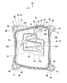
また、図7を参照し、図中で説明便宜上、二点鎖線で示すが、側壁部31Aの内面側の周縁部には、樹脂製の矩形状のカバー板35が溶着されており、これにより、側壁部31A及び天壁部31Bで囲われる空間を内部側から覆うことで、ブリーザ室31が形成されている。
そして、ブリーザ室31の側壁部31Aには下方に開放した導入口31Dが形成されており、ブリーザ室31の天壁部31Bの内面には、ヘッドカバー25の内部で生じたブローバイガスを、導入口31Dから図中矢印Dに示すように蛇行させて排出口32Aまで導くラビリンス壁34が形成されている。このラビリンス壁34は天壁部31Bから立ち上がるように、天壁部31Bに一体に形成されている。これにより、導入口31Dから導入されたブローバイガスがラビリンス壁34に沿って蛇行して排出口32Aから排出され、ラビリンス壁34があることで液体が排出口32Aから排出されることが防止される(つまり、気液分離が行われる)。
Further, referring to FIG. 7, for convenience of explanation in the drawing, a two-dot chain line indicates that a resin-made rectangular cover plate 35 is welded to the peripheral portion on the inner surface side of the side wall portion 31 </ b> A. The breather chamber 31 is formed by covering the space surrounded by the side wall portion 31A and the top wall portion 31B from the inner side.
An inlet 31D opened downward is formed in the side wall 31A of the breather chamber 31, and blow-by gas generated inside the head cover 25 is introduced into the inner surface of the top wall 31B of the breather chamber 31. A labyrinth wall 34 is formed so as to meander from 31D to the discharge port 32A as indicated by an arrow D in the figure. The labyrinth wall 34 is formed integrally with the top wall portion 31B so as to rise from the top wall portion 31B. Thereby, the blow-by gas introduced from the introduction port 31D meanders along the labyrinth wall 34 and is discharged from the discharge port 32A, and the presence of the labyrinth wall 34 prevents liquid from being discharged from the discharge port 32A. (In other words, gas-liquid separation is performed).

図7には、ヘッドカバー25に取り付けられた状態のガスケット40が示されており、内燃機関2においては、シリンダヘッド24とヘッドカバー25との結合面(後述するヘッド側結合面37及びカバー側結合面36)に、ガスケット40が挟持される。図8、図9には、シリンダヘッド24とガスケット40とが示されるが、本実施形態の内燃機関2では、詳細は後述するが、ガスケット40がヘッドカバー25に小組み状態とされてから、ヘッドカバー25がシリンダヘッド24に締結され、これに伴い、シリンダヘッド24とヘッドカバー25との間にガスケット40が挟持されるようになっている。なお、本実施形態の説明で用いる図面には、説明便宜上、ガスケット40にドット付している場合がある。   FIG. 7 shows the gasket 40 attached to the head cover 25. In the internal combustion engine 2, the coupling surface between the cylinder head 24 and the head cover 25 (a head-side coupling surface 37 and a cover-side coupling surface described later). 36) the gasket 40 is sandwiched. 8 and 9, the cylinder head 24 and the gasket 40 are shown. In the internal combustion engine 2 of the present embodiment, the details of the cylinder head 24 and the gasket 40 will be described later. 25 is fastened to the cylinder head 24, and accordingly, the gasket 40 is sandwiched between the cylinder head 24 and the head cover 25. In the drawings used in the description of the present embodiment, for convenience of explanation, the gasket 40 may be dotted.

図10には、ガスケット40が取り外された状態のヘッドカバー25が示されており、図7、図10を参照し、ヘッドカバー25の周壁部25Bにおけるシリンダヘッド24側を向く矩形状(矩形枠状)の端面には、ヘッドカバー25がガスケット40を介してシリンダヘッド24に当接して結合するカバー側結合面36が設定されている。なお、カバー側結合面36は矩形状(矩形枠状)を呈する。
一方で、図8、図9を参照し、シリンダヘッド24においては、ヘッドカバー25側に向く、矩形状(矩形枠状)の端面に、シリンダヘッド24がガスケット40を介してヘッドカバー25に当接して結合するヘッド側結合面37が設定される。なお、ヘッド側結合面37も矩形状(矩形枠状)を呈する。
カバー側結合面36及びヘッド側結合面37は、ヘッドカバー25とシリンダヘッド24とで形成する空間である動弁室を、ガスケット40を介してシール及び結合する面である。
FIG. 10 shows the head cover 25 with the gasket 40 removed. Referring to FIGS. 7 and 10, a rectangular shape (rectangular frame shape) facing the cylinder head 24 side in the peripheral wall portion 25 </ b> B of the head cover 25. A cover side coupling surface 36 on which the head cover 25 abuts on the cylinder head 24 via the gasket 40 and couples to the cylinder head 24 is set on the end surface. The cover side coupling surface 36 has a rectangular shape (rectangular frame shape).
On the other hand, referring to FIGS. 8 and 9, in the cylinder head 24, the cylinder head 24 abuts the head cover 25 via the gasket 40 on the end surface of the rectangular shape (rectangular frame shape) facing the head cover 25 side. A head side coupling surface 37 to be coupled is set. The head side coupling surface 37 also has a rectangular shape (rectangular frame shape).
The cover side coupling surface 36 and the head side coupling surface 37 are surfaces that seal and couple the valve operating chamber, which is a space formed by the head cover 25 and the cylinder head 24, via the gasket 40.

図7、図11及び図12を参照し、本実施形態のガスケット40は弾性変形可能なたとえばゴム製とされ、ヘッドカバー25のカバー側結合面36に沿って矩形枠状に形成されたガスケット本体41と、ガスケット本体41の四隅の角部から外方(動弁室側の反対側の方向)に向けて膨出する4つのフランジ当接部42と、ガスケット本体41からヘッドカバー25側に向けて突出する嵌合壁部43と、を一体に有している。嵌合壁部43は、矩形枠状のガスケット本体41の全域にわたって連続して形成されている。   Referring to FIGS. 7, 11, and 12, the gasket 40 of the present embodiment is made of, for example, rubber that can be elastically deformed, and is formed in a rectangular frame shape along the cover side coupling surface 36 of the head cover 25. And four flange contact portions 42 that bulge outward from the corners of the four corners of the gasket body 41 (in the direction opposite to the valve operating chamber side), and project from the gasket body 41 toward the head cover 25 side. And a fitting wall portion 43 to be integrated. The fitting wall 43 is continuously formed over the entire area of the rectangular frame-shaped gasket body 41.

図10を参照し、ヘッドカバー25のカバー側結合面36には、カバー側結合面36の全域にわたって連続して、矩形状をなすガスケット嵌合溝44が形成されている。ガスケット嵌合溝44は嵌合壁部43に整合しており、嵌合壁部43がガスケット嵌合溝44に嵌合されることで、図7に示すように、ガスケット40がヘッドカバー25に小組み状態となるように、ガスケット40は構成されている。
なお、図11、図12を参照し、嵌合壁部43は、ガスケット嵌合溝44に隙間をもって挿入される矩形枠状の本体43Aと、本体43Aの外周面及び内周面にそれぞれ形成され、当該外周面及び内周面の全周にわたって連続して延び、かつガスケット嵌合溝44の側壁部分に当接する当接リブ43Bと、当接リブ43Bに直交して延び、本体43Aの外周面及び内周面において間隔を空けて複数形成された補強リブ43Cと、を一体に有している。
Referring to FIG. 10, a gasket fitting groove 44 having a rectangular shape is formed on the cover side coupling surface 36 of the head cover 25 continuously over the entire area of the cover side coupling surface 36. The gasket fitting groove 44 is aligned with the fitting wall portion 43. By fitting the fitting wall portion 43 into the gasket fitting groove 44, the gasket 40 is small in the head cover 25 as shown in FIG. The gasket 40 is configured so as to be assembled.
11 and 12, the fitting wall portions 43 are respectively formed on a rectangular frame-like main body 43A inserted into the gasket fitting groove 44 with a gap, and on the outer peripheral surface and the inner peripheral surface of the main body 43A. The contact rib 43B continuously extending over the entire circumference of the outer peripheral surface and the inner peripheral surface, and contacting the side wall portion of the gasket fitting groove 44, and extending perpendicular to the contact rib 43B, and the outer peripheral surface of the main body 43A And a plurality of reinforcing ribs 43C formed at intervals on the inner peripheral surface.

図6、図8、図9等を参照し、シリンダヘッド24のヘッド側結合面37の四隅の角部それぞれには、外方(動弁室側の反対側の方向)に膨出するヘッド側フランジ部45が一体に形成され、ヘッド側フランジ部45にはそれぞれ、シリンダ軸線S1方向に沿って延びる雌ねじ穴46が形成されている。また、図10を参照し、ヘッドカバー25のカバー側結合面36の四隅の角部それぞれにも同様に、外方(動弁室側の反対側の方向)に膨出するカバー側フランジ部48が形成され、カバー側フランジ部48にはそれぞれボルトを挿通させる挿通穴49が形成されている。
そして図4〜図6を参照し、挿通穴49にはボルト50が挿通され、この挿通されたボルト50がヘッド側フランジ部45の雌ねじ穴46に締結されることで、ヘッドカバー25がシリンダヘッド24に締結される。このとき、ボルト50はガスケット40のフランジ当接部42に形成された貫通穴51(図7、図11、図12等参照)に通されている。
そして、ガスケット40は、カバー側結合面36とヘッド側結合面37との間、及びカバー側フランジ部48とヘッド側フランジ部45との間全体に渡って位置しており、フランジ当接部42は、表裏(ヘッドカバー側及びシリンダヘッド側)でカバー側フランジ部48とヘッド側フランジ部45とに対向する状態となる。そして、ガスケット40は、ボルト50が締め上げられることで、カバー側結合面36とヘッド側結合面37との間で弾性変形(圧縮)した状態で挟み込まれて(挟圧されて)、カバー側結合面36とヘッド側結合面37との間をシールする(動弁室をシールする)ことになる。
6, 8, 9, etc., each of the four corners of the head-side coupling surface 37 of the cylinder head 24 is swelled outward (in the direction opposite to the valve operating chamber side). A flange portion 45 is formed integrally, and each of the head side flange portions 45 is formed with a female screw hole 46 extending along the direction of the cylinder axis S1. Referring to FIG. 10, similarly, cover side flange portions 48 that bulge outward (in the direction opposite to the valve operating chamber side) are similarly formed at the four corners of the cover side coupling surface 36 of the head cover 25. The cover side flange portion 48 is formed with an insertion hole 49 through which a bolt is inserted.
4 to 6, a bolt 50 is inserted into the insertion hole 49, and the inserted bolt 50 is fastened to the female screw hole 46 of the head side flange portion 45, so that the head cover 25 is connected to the cylinder head 24. To be concluded. At this time, the bolt 50 is passed through a through hole 51 (see FIGS. 7, 11, 12, etc.) formed in the flange contact portion 42 of the gasket 40.
The gasket 40 is located between the cover side coupling surface 36 and the head side coupling surface 37 and between the cover side flange portion 48 and the head side flange portion 45, and the flange contact portion 42. Is in a state of facing the cover side flange portion 48 and the head side flange portion 45 on the front and back sides (head cover side and cylinder head side). The gasket 40 is sandwiched (clamped) in an elastically deformed (compressed) state between the cover-side coupling surface 36 and the head-side coupling surface 37 by tightening the bolt 50, and the cover side The space between the coupling surface 36 and the head-side coupling surface 37 is sealed (the valve operating chamber is sealed).

本実施形態の内燃機関2では、シリンダ部22におけるガスケット40が挟持される部位のうち、車両への搭載状態で、シリンダヘッド24及びヘッドカバー25の上壁に対応する位置にある部位に、ガスケット40が最も低面圧で挟持される、図7〜図9で便宜上二点鎖線で示す低面圧部55が形成される。低面圧部55は、内燃機関2内の内圧が必要以上に高まってしまった場合に、圧抜き、すなわちブローバイガスを排出させるために設けられる。なお、図7〜図9において低面圧部55が位置する領域は、ガスケット40に付したドットよりも濃度の濃いドットを付して強調して示してある。   In the internal combustion engine 2 of the present embodiment, the gasket 40 is located at a position corresponding to the upper walls of the cylinder head 24 and the head cover 25 when mounted on the vehicle, of the portions of the cylinder portion 22 where the gasket 40 is sandwiched. Is formed with a low surface pressure portion 55 indicated by a two-dot chain line for convenience in FIGS. 7 to 9. The low surface pressure portion 55 is provided to release pressure, that is, to discharge blow-by gas when the internal pressure in the internal combustion engine 2 has increased more than necessary. 7 to 9, the region where the low surface pressure portion 55 is located is highlighted with dots having a higher density than the dots attached to the gasket 40.

低面圧部55は、左右上側に位置するヘッド側フランジ部45及びカバー側フランジ部48との間に位置する部位のうちの、左右方向で中央の位置よりもやや右側(内燃機関2の左右方向における略中央)に設けられている。なお、このような低面圧部55の配置位置は、この例に限られるものでないことはいうまでも無い。低面圧部55は、例えば、ヘッドカバー25の締結方向におけるガスケット40の高さを、局部的に周囲の部分よりも低くすることで形成される。   The low surface pressure portion 55 is located slightly to the right of the center position in the left and right direction (the left and right sides of the internal combustion engine 2) among the portions located between the head side flange portion 45 and the cover side flange portion 48 located on the upper left and right sides. At approximately the center in the direction). Needless to say, the arrangement position of the low surface pressure portion 55 is not limited to this example. The low surface pressure portion 55 is formed, for example, by locally lowering the height of the gasket 40 in the fastening direction of the head cover 25 than the surrounding portion.

また、本実施形態では、図8、図9に示すように、シリンダヘッド24のヘッド側結合面37のうちの、低面圧部55が形成された部位の下方(内側、すなわち動弁室側)には、ヘッド側オイル通路形成面37Aが形成されており、このヘッド側オイル通路形成面37Aに、当該面からシリンダブロック23側に延びるヘッド側オイル通路57(図8参照)が形成されている。
また、図7、図10に示すように、ヘッドカバー25のカバー側結合面36のうちの、低面圧部55が形成される部位の下方(内側、すなわち動弁室側)には、カバー側オイル通路形成面36Aが形成されており、カバー側オイル通路形成面36Aには、ヘッド側オイル通路57に連通するカバー側オイル通路58が形成されている。
なお、ヘッド側オイル通路形成面37Aは、シリンダヘッド24に一体に形成され、カバー側オイル通路形成面36Aは、ヘッドカバー25に一体に形成されている。
Further, in the present embodiment, as shown in FIGS. 8 and 9, below the portion of the head side coupling surface 37 of the cylinder head 24 where the low surface pressure portion 55 is formed (inside, that is, on the valve operating chamber side). ) Is formed with a head side oil passage forming surface 37A, and a head side oil passage 57 (see FIG. 8) extending from the surface to the cylinder block 23 side is formed on the head side oil passage forming surface 37A. Yes.
Further, as shown in FIGS. 7 and 10, the cover side of the cover side coupling surface 36 of the head cover 25 is below the portion where the low surface pressure portion 55 is formed (inside, that is, the valve operating chamber side). An oil passage forming surface 36A is formed, and a cover side oil passage 58 communicating with the head side oil passage 57 is formed on the cover side oil passage forming surface 36A.
The head side oil passage forming surface 37A is formed integrally with the cylinder head 24, and the cover side oil passage forming surface 36A is formed integrally with the head cover 25.

そして、ヘッド側オイル通路57とカバー側オイル通路58との間には、これら各通路57,58の開口縁の周囲を覆うとともに各通路57,58を連通させるオイルシール部60が配置されており、本実施形態では、このオイルシール部60がガスケット本体41に一体に形成されている。オイルシール部60は低面圧部55の下方に位置しているため、低面圧部55は、オイルシール部60の上方でオイルシール部60に隣接して設けられている。オイルシール部60は、左右方向に長手方向を沿わせた矩形状に形成されている。ヘッド側オイル通路57、カバー側オイル通路58及びオイルシール部60は、カムシャフト等の潤滑のためのオイル経路を構成している。オイルシール部60には、ヘッド側オイル通路57とカバー側オイル通路58と連通させるための連通穴62が形成されている。   Between the head-side oil passage 57 and the cover-side oil passage 58, an oil seal portion 60 that covers the periphery of the opening edge of each of the passages 57, 58 and communicates the passages 57, 58 is disposed. In this embodiment, the oil seal portion 60 is formed integrally with the gasket body 41. Since the oil seal portion 60 is located below the low surface pressure portion 55, the low surface pressure portion 55 is provided adjacent to the oil seal portion 60 above the oil seal portion 60. The oil seal portion 60 is formed in a rectangular shape along the longitudinal direction in the left-right direction. The head side oil passage 57, the cover side oil passage 58, and the oil seal portion 60 constitute an oil passage for lubricating the camshaft and the like. The oil seal portion 60 is formed with a communication hole 62 for communicating with the head side oil passage 57 and the cover side oil passage 58.

また、図8、図9において、シリンダヘッド24の内側には、シリンダ軸線S1から見て右上、左上、右下、左下の位置に、シリンダ軸線S1に沿って延びるボス部61が形成され、ヘッド側オイル通路57は、一部が右上に位置するボス部61を通るように形成されている。シリンダヘッド24は、ボス部61それぞれに挿通させた図示省略するスタッドボルトをシリンダブロック23に締結することで、シリンダブロック23に結合される。ボス部61は、シリンダ軸線S1方向で、ヘッド側結合面37よりもヘッドカバー25側に突出するように形成されている。   8 and 9, a boss portion 61 extending along the cylinder axis S1 is formed on the inner side of the cylinder head 24 at positions on the upper right, upper left, lower right, and lower left when viewed from the cylinder axis S1. The side oil passage 57 is formed so that a part thereof passes through the boss portion 61 located on the upper right. The cylinder head 24 is coupled to the cylinder block 23 by fastening stud bolts (not shown) inserted through the boss portions 61 to the cylinder block 23. The boss portion 61 is formed so as to protrude toward the head cover 25 side from the head side coupling surface 37 in the cylinder axis S1 direction.

また、図7、図10を参照し、本実施形態では、ヘッドカバー25においては、低面圧部55を構成する部位と、カバー側オイル通路58との間に、低面圧部55の内側面(動弁室側の面)を、内燃機関2の内部(動弁室)側から覆う壁部65が、カバー側結合面36及びカバー側オイル通路形成面36Aよりも突出して立設されている。   7 and 10, in the present embodiment, in the head cover 25, the inner surface of the low surface pressure portion 55 is disposed between the portion constituting the low surface pressure portion 55 and the cover side oil passage 58. A wall portion 65 that covers the (valve chamber side surface) from the inside (valve chamber) side of the internal combustion engine 2 protrudes from the cover side coupling surface 36 and the cover side oil passage forming surface 36A. .

壁部65は左右方向に長い板状に形成され、オイルシール部60とガスケット40(ガスケット本体41)とを連結させる連結部67に形成されたスリット穴66に挿入されるようになっている。これにより、ガスケット40のヘッドカバー25への組付け性の向上が図られている。   The wall portion 65 is formed in a plate shape that is long in the left-right direction, and is inserted into a slit hole 66 formed in a connecting portion 67 that connects the oil seal portion 60 and the gasket 40 (gasket body 41). Thereby, the assembling property of the gasket 40 to the head cover 25 is improved.

以下では、ガスケット40についてさらに詳述する。図11〜図13を参照し、ガスケット40のフランジ当接部42それぞれには、貫通穴51の軸方向に沿う厚み寸法が、動弁室側よりもヘッド側フランジ部45及びカバー側フランジ部48の先端部である膨出端部45A,48A側(図8、図10参照)の方が大きくなるように厚肉部70が形成されている。一方、フランジ当接部42のうちの厚肉部70が形成された部位以外の部位は、厚肉部70よりも薄く板状となっており、以下では、この厚肉部70よりも薄い板状の部位を、非厚肉部71と呼ぶものとする。
なお、図中符合L4は、貫通穴51の中心軸線を示している。また、図13には、ガスケット40の4つのフランジ当接部42のうちの、右上方に位置するフランジ当接部42が示されている。
Below, the gasket 40 is further explained in full detail. 11 to 13, each flange contact portion 42 of the gasket 40 has a thickness dimension along the axial direction of the through hole 51 such that the head side flange portion 45 and the cover side flange portion 48 are closer to the valve operating chamber side. The thick portion 70 is formed so that the bulging end portions 45A and 48A side (see FIGS. 8 and 10), which are the leading end portions, become larger. On the other hand, a portion of the flange contact portion 42 other than the portion where the thick portion 70 is formed has a plate shape that is thinner than the thick portion 70, and hereinafter, a plate that is thinner than the thick portion 70. The shape portion is referred to as a non-thick portion 71.
In the drawing, the symbol L4 indicates the central axis of the through hole 51. FIG. 13 shows the flange contact portion 42 located on the upper right side of the four flange contact portions 42 of the gasket 40.

本実施形態において厚肉部70は、フランジ当接部42におけるヘッド側フランジ部45及びカバー側フランジ部48の膨出端部45A,48A側の位置で、貫通穴51の周囲に形成され、貫通穴51の周方向に延びる円弧状に形成されている。厚肉部70はそれぞれ、ガスケット40の中央側(動弁室のシリンダ軸線S1に対する径方向における断面の中央側)に向けて開放した状態となっている。   In the present embodiment, the thick portion 70 is formed around the through hole 51 at a position of the flange contact portion 42 on the head side flange portion 45 and the bulging end portions 45A and 48A side of the cover side flange portion 48. It is formed in an arc shape extending in the circumferential direction of the hole 51. Each of the thick portions 70 is open toward the center side of the gasket 40 (the center side of the cross section in the radial direction with respect to the cylinder axis S1 of the valve operating chamber).

ここで、図14を参照し、同図には、ガスケット40の嵌合壁部43がヘッドカバー25のガスケット嵌合溝44に嵌合され、ガスケット40がヘッドカバー25に組み付けられた状態のフランジ当接部42周辺の図11のA−A線に対応する断面が示されている。
図14の状態では、カバー側フランジ部48の挿通穴49の中心軸線とフランジ当接部42の貫通穴51の中心軸線が一致し、厚肉部70及び非厚肉部71のヘッドカバー25側を向く面が、カバー側フランジ部48のガスケット40側を向く面における挿通穴49の周囲(周縁部)と対向した状態となっている。
Here, referring to FIG. 14, the flange abutting state in which the fitting wall portion 43 of the gasket 40 is fitted into the gasket fitting groove 44 of the head cover 25 and the gasket 40 is assembled to the head cover 25 is shown. The cross section corresponding to the AA line of FIG. 11 around the portion 42 is shown.
In the state of FIG. 14, the center axis of the insertion hole 49 of the cover side flange portion 48 and the center axis of the through hole 51 of the flange abutting portion 42 coincide with each other, and the thick cover 70 and the non-thick portion 71 are connected to the head cover 25 side. The facing surface is in a state of facing the periphery (peripheral portion) of the insertion hole 49 in the surface facing the gasket 40 side of the cover side flange portion 48.

厚肉部70のヘッドカバー25側を向く面は、非厚肉部71のヘッドカバー25側を向く面よりも、ヘッドカバー25側に張り出した位置にあり、厚肉部70のシリンダヘッド24側を向く面も、非厚肉部71のシリンダヘッド24側を向く面よりも、シリンダヘッド24側に張り出した位置にある。一方で、厚肉部70のシリンダヘッド24側を向く面は、ガスケット本体41のシリンダヘッド24側を向く面と略同一面上に位置する。   The surface of the thick portion 70 facing the head cover 25 side is located at a position protruding to the head cover 25 side of the non-thick portion 71 facing the head cover 25 side, and the surface of the thick portion 70 facing the cylinder head 24 side. Also, it is at a position protruding to the cylinder head 24 side from the surface of the non-thick portion 71 facing the cylinder head 24 side. On the other hand, the surface of the thick portion 70 facing the cylinder head 24 side is located on substantially the same plane as the surface of the gasket body 41 facing the cylinder head 24 side.

ヘッドカバー25をシリンダヘッド24に組み付ける際には、図14に示す状態から、まず、フランジ当接部42のシリンダヘッド24側を向く面を、図15に示すように、シリンダヘッド24のヘッド側フランジ部45に当接させる。そして、カバー側フランジ部48の挿通穴49、フランジ当接部42の貫通穴51を通過したボルト50を、ヘッド側フランジ部45の雌ねじ穴46に螺合させる。なお、貫通穴51は雌ねじ穴46よりも大径になっている。   When the head cover 25 is assembled to the cylinder head 24, from the state shown in FIG. 14, first, the surface of the flange contact portion 42 facing the cylinder head 24 side is set to the head side flange of the cylinder head 24 as shown in FIG. It abuts on the part 45. Then, the bolt 50 that has passed through the insertion hole 49 of the cover side flange portion 48 and the through hole 51 of the flange contact portion 42 is screwed into the female screw hole 46 of the head side flange portion 45. The through hole 51 has a larger diameter than the female screw hole 46.

本実施形態においてボルト50は段付きボルトであり、円柱状の基軸部50Aと、基軸部50Aよりも小径に形成されるとともに基軸部50Aの一端面中央領域から突出し、その外周に螺子切りが施された雄ねじ部50Bと、雄ねじ部50Bが連結する側と反対側の基軸部50Aの端面である他端面側に形成され、基軸部50Aから張り出す環状のフランジ部50Cを有する頭部50Dと、で構成され、雄ねじ部50Bと基軸部50Aとが連結する基軸部50Aの一端面には、段差面50Eが形成される。   In this embodiment, the bolt 50 is a stepped bolt, and is formed in a columnar base shaft portion 50A and a diameter smaller than that of the base shaft portion 50A, protrudes from a central region of one end surface of the base shaft portion 50A, and is threaded on the outer periphery thereof. A head portion 50D having an annular flange portion 50C that is formed on the other end surface side that is an end surface of the base shaft portion 50A opposite to the side to which the male screw portion 50B is coupled, and that projects from the base shaft portion 50A; A step surface 50E is formed on one end surface of the base shaft portion 50A where the male screw portion 50B and the base shaft portion 50A are connected.

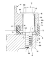
ボルト50をヘッド側フランジ部45の雌ねじ穴46に締結していく際は、まず、図15に示すように、頭部50Dにおけるフランジ部50Cを、カバー側フランジ部48の挿通穴49の周囲の部位(周縁部)に当接させ、さらに締結を進めた場合に、ヘッドカバー25がシリンダヘッド24に近づく状態にする。そして、次に、締結状態を、図16に示すように、カバー側フランジ部48のガスケット40側を向く面における挿通穴49の周縁部が、厚肉部70に当接する状態にし(図中、ta1で示す状態)、さらに締結を進めた場合に、ヘッドカバー25がシリンダヘッド24に近づきつつ、厚肉部70が圧縮される状態にする。   When fastening the bolt 50 to the female screw hole 46 of the head side flange portion 45, first, as shown in FIG. 15, the flange portion 50C of the head portion 50D is placed around the insertion hole 49 of the cover side flange portion 48. The head cover 25 is brought into a state of approaching the cylinder head 24 when it is brought into contact with the portion (peripheral portion) and further tightening is advanced. Next, as shown in FIG. 16, the fastening state is set so that the peripheral edge portion of the insertion hole 49 in the surface facing the gasket 40 side of the cover side flange portion 48 is in contact with the thick portion 70 (in the drawing, When the fastening is further advanced, the thick cover 70 is compressed while the head cover 25 approaches the cylinder head 24.

その後、所定の圧縮量だけボルト50を締結して、図17に示すように、ボルト50の段差面50Eがシリンダヘッド24のヘッド側フランジ部45の端面に当接した状態で取り付けが完了する。   Thereafter, the bolt 50 is fastened by a predetermined compression amount, and the mounting is completed in a state where the stepped surface 50E of the bolt 50 is in contact with the end surface of the head side flange portion 45 of the cylinder head 24 as shown in FIG.

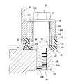
ここで、ボルト50を段付きボルトとするのは、締結量(螺合代)を所定量に規定し、締めすぎを防止するためである。本実施形態では、ボルト50の段差面50Eの位置が、厚肉部70と非厚肉部71とがともに圧縮され、かつ図17に示すように、厚肉部70の圧縮量P1が非厚肉部71の圧縮量P2よりも大きくなるように設定されている。なお、図17では、二点鎖線で圧縮前の厚肉部70及び非厚肉部71を便宜上示している。
さらに、ボルト50では、基軸部50Aの直径が、カバー側フランジ部48の挿通穴49の内径よりもわずかに小さく、基軸部50Aが挿通穴49に挿通された際に、双方の間にわずかな隙間が形成されるようになっている。また、本実施形態のヘッドカバー25は、ガスケット40を介してシリンダヘッド24にフローティング支持される状態となっている。すなわち、ヘッドカバー25は、ガスケット40を介してシリンダヘッド24から離間した状態が維持されて、シリンダヘッド24に固定支持される状態となっている。
Here, the reason why the bolt 50 is a stepped bolt is to regulate the fastening amount (screwing allowance) to a predetermined amount and prevent overtightening. In the present embodiment, the position of the stepped surface 50E of the bolt 50 is such that the thick portion 70 and the non-thick portion 71 are both compressed, and the compression amount P1 of the thick portion 70 is non-thick as shown in FIG. It is set to be larger than the compression amount P2 of the meat portion 71. In FIG. 17, the thick portion 70 and the non-thick portion 71 before compression are indicated by a two-dot chain line for convenience.
Further, in the bolt 50, the diameter of the base shaft portion 50A is slightly smaller than the inner diameter of the insertion hole 49 of the cover side flange portion 48, and when the base shaft portion 50A is inserted through the insertion hole 49, the diameter is slightly between both. A gap is formed. In addition, the head cover 25 of the present embodiment is in a state of being floating supported by the cylinder head 24 via the gasket 40. That is, the head cover 25 is maintained in a state of being separated from the cylinder head 24 via the gasket 40 and is fixedly supported by the cylinder head 24.

また、図11〜図13に戻り、本実施形態では、フランジ当接部42の厚肉部70におけるヘッド側フランジ部45及びカバー側フランジ部48の膨出端部45A,48A側に、図6等に示すようにカバー側フランジ部48の外周壁(膨出端部48A側の外周壁)に沿って、貫通穴51の軸方向に延出するとともに、カバー側フランジ部48の外周壁に密着する円弧状の保持壁部72が、一体に形成されている。   Returning to FIGS. 11 to 13, in the present embodiment, the head-side flange portion 45 and the cover-side flange portion 48 at the bulging end portions 45 </ b> A and 48 </ b> A side of the thick-walled portion 70 of the flange contact portion 42, FIG. As shown in the figure, it extends in the axial direction of the through hole 51 along the outer peripheral wall of the cover-side flange portion 48 (the outer peripheral wall on the bulging end portion 48A side) and is in close contact with the outer peripheral wall of the cover-side flange portion 48. An arc-shaped holding wall portion 72 is integrally formed.

この保持壁部72は、例えば、図17に示すように、カバー側フランジ部48の外周壁を覆うようにして密着し、ガスケット40のヘッドカバー25に対する保持力を向上させる。保持壁部72は、貫通穴51の軸方向で見た場合に、円弧状に形成され厚肉部70の両端部間に渡って形成されている。   For example, as shown in FIG. 17, the holding wall portion 72 is in close contact with the outer peripheral wall of the cover-side flange portion 48 to improve the holding force of the gasket 40 on the head cover 25. When viewed in the axial direction of the through hole 51, the holding wall portion 72 is formed in an arc shape and is formed between both end portions of the thick portion 70.

また本実施形態では、保持壁部72にはそれぞれ、図10に示すカバー側フランジ部48の外周壁(膨出端部48Aの外周壁)に設けられた第1の被係合部80に対して係合可能な第1の係合部73が形成されている(図11参照)。第1の被係合部80は、膨出端部48Aの外周壁の最先端部分から動弁室側に向けて凹む切欠きによって形成されている。第1の係合部73は、保持壁部72において、膨出端部48Aの外周壁の最先端部分に対応する部位(貫通穴51の軸方向で見た場合に膨出端部48Aの外周壁の最先端部分に重なる部位)から動弁室側に向けて突出して形成されている。   In the present embodiment, each holding wall 72 has a first engagement portion 80 provided on the outer peripheral wall of the cover-side flange portion 48 shown in FIG. 10 (the outer peripheral wall of the bulging end portion 48A). The first engaging portion 73 that can be engaged is formed (see FIG. 11). The first engaged portion 80 is formed by a notch that is recessed from the most distal end portion of the outer peripheral wall of the bulging end portion 48A toward the valve operating chamber side. The first engaging portion 73 is a portion of the holding wall 72 corresponding to the most distal portion of the outer peripheral wall of the bulging end portion 48A (the outer periphery of the bulging end portion 48A when viewed in the axial direction of the through hole 51). It is formed so as to protrude toward the valve train chamber side from a portion overlapping the most advanced portion of the wall.

第1の係合部73は、ガスケット40のヘッドカバー25に対する保持力を向上させるために形成されており、図14に示すように、ヘッドカバー25とガスケット40の組み付けの段階で、第1の被係合部80に係合される。詳しくは、第1の係合部73は、第1の被係合部80に嵌め込まれ、保持壁部72の弧状部分の延在方向(直線L4に直交する方向)における移動を規制する。   The first engaging portion 73 is formed to improve the holding force of the gasket 40 with respect to the head cover 25. As shown in FIG. 14, the first engaged portion 73 is formed at the stage of assembling the head cover 25 and the gasket 40. The joint 80 is engaged. Specifically, the first engaging portion 73 is fitted into the first engaged portion 80 and restricts the movement of the arcuate portion of the holding wall portion 72 in the extending direction (direction orthogonal to the straight line L4).

また、本実施形態では、ガスケット40において、貫通穴51を挟んで第1の係合部73と対向する位置に、第2の係合部74が形成されている。第2の係合部74は、ガスケット40における嵌合壁部43の内周面から動弁室側に向けて突出して形成されている。一方で、図10を参照し、ヘッドカバー25においては、ガスケット嵌合溝44に、第2の係合部74を係合可能とする第2の被係合部81が形成されている。第2の被係合部81は、ガスケット嵌合溝44の内周面から動弁室側に向けて凹む切欠きによって形成されている。   In the present embodiment, a second engagement portion 74 is formed in the gasket 40 at a position facing the first engagement portion 73 with the through hole 51 interposed therebetween. The second engaging portion 74 is formed to protrude from the inner peripheral surface of the fitting wall portion 43 in the gasket 40 toward the valve operating chamber side. On the other hand, referring to FIG. 10, in the head cover 25, a second engaged portion 81 that allows the second engaging portion 74 to be engaged is formed in the gasket fitting groove 44. The second engaged portion 81 is formed by a notch that is recessed from the inner peripheral surface of the gasket fitting groove 44 toward the valve operating chamber side.

第2の係合部74は、ガスケット40のヘッドカバー25に対する保持力を向上させるために形成されており、図14に示すように、ヘッドカバー25とガスケット40の組み付けの段階で、第2の被係合部81に係合される。第2の係合部74は、第2の被係合部81に嵌め込まれ、ガスケット本体41の延在方向(直線L4に直交する方向)における移動を規制する。   The second engaging portion 74 is formed in order to improve the holding force of the gasket 40 with respect to the head cover 25. As shown in FIG. 14, the second engaging portion 74 is in the stage where the head cover 25 and the gasket 40 are assembled. Engage with the joint 81. The second engaging portion 74 is fitted into the second engaged portion 81 and restricts the movement of the gasket body 41 in the extending direction (direction orthogonal to the straight line L4).

以上に記載したように本実施形態に係る構造では、樹脂製のヘッドカバー25とヘッドカバー25の被結合部材であるシリンダヘッド24とが締結部材であるボルト50によって結合されて内部に空間である動弁室が形成され、ヘッドカバー25及びシリンダヘッド24には、動弁室を囲んでシールするヘッドカバー25とシリンダヘッド24との結合面であるカバー側結合面36及びヘッド側結合面37から、動弁室の外方に向けて膨出するとともに、ボルト50によって互いに締結されるフランジ部であるカバー側フランジ部48及びヘッド側フランジ部45がそれぞれ形成され、カバー側結合面36及びヘッド側結合面37、カバー側フランジ部48及びヘッド側フランジ部45に渡ってガスケット40が挟持される。そして、ヘッドカバー25及びシリンダヘッド24それぞれのカバー側フランジ部48及びヘッド側フランジ部45に対向するガスケット40におけるフランジ当接部42には、ボルト50を貫通させる貫通穴51が形成され、このフランジ当接部42には、貫通穴51の軸方向に沿う厚み寸法が、動弁室側よりもカバー側フランジ部48及びヘッド側フランジ部45の膨出端部48A,45A側の方が大きくなるように厚肉部70が形成される。   As described above, in the structure according to the present embodiment, the resin-made head cover 25 and the cylinder head 24 that is the coupled member of the head cover 25 are coupled by the bolt 50 that is the fastening member, and the valve is a space inside. A chamber is formed, and the head cover 25 and the cylinder head 24 include a valve-side chamber from a cover-side coupling surface 36 and a head-side coupling surface 37 that are coupling surfaces of the head cover 25 and the cylinder head 24 that surround and seal the valve-valve chamber. The cover side flange portion 48 and the head side flange portion 45, which are flange portions fastened to each other by the bolt 50, are respectively formed, and the cover side coupling surface 36 and the head side coupling surface 37 are formed. The gasket 40 is sandwiched across the cover side flange portion 48 and the head side flange portion 45. A through hole 51 through which the bolt 50 passes is formed in the flange contact portion 42 of the gasket 40 facing the cover side flange portion 48 and the head side flange portion 45 of the head cover 25 and the cylinder head 24, respectively. The contact portion 42 has a thickness dimension along the axial direction of the through hole 51 so that the cover side flange portion 48 and the bulging end portions 48A and 45A side of the head side flange portion 45 are larger than the valve chamber side. A thick portion 70 is formed.

このような構造では、ヘッドカバー25とシリンダヘッド24とがガスケット40を挟持して、カバー側フランジ部48及びヘッド側フランジ部45で締結固定される際は、締結に伴ってヘッドカバー25におけるボルト50周りの特に外方側、すなわちカバー側フランジ部48及びヘッド側フランジ部45の膨出端部48A,45A側が、シリンダヘッド24に近づく方向へ向けて特に撓みや変形を起こしやすくなるが、ガスケット40におけるフランジ当接部42には、ボルト50が貫通する貫通穴51の軸方向に沿う厚み寸法が、動弁室側よりもカバー側フランジ部48及びヘッド側フランジ部45の膨出端部48A,45A側の方が大きくなるように、厚肉部70を形成したので、ボルト50周りの特に外方側、すなわちカバー側フランジ部48及びヘッド側フランジ部45の膨出端部48A,45A側のガスケット40の反力を高めて、ヘッドカバー25がシリンダヘッド24に近づく方向へ向けて撓もうとするのを抑制することができる。さらに、ボルト50周りでのヘッドカバー25の撓みや変形を抑制することで、ボルト50から離れたヘッドカバー25の部位の撓みや変形も合わせて抑制することができる。これにより、この構造では、ヘッドカバー25とシリンダヘッド24との結合部分に安定したシール性を確保することができる。   In such a structure, when the head cover 25 and the cylinder head 24 sandwich the gasket 40 and are fastened and fixed by the cover side flange portion 48 and the head side flange portion 45, the bolts 50 around the head cover 25 are tightened together with the fastening. In particular, the outer side, that is, the bulging end portions 48A and 45A side of the cover side flange portion 48 and the head side flange portion 45 are likely to bend and deform in the direction approaching the cylinder head 24. The flange abutting portion 42 has a thickness dimension along the axial direction of the through hole 51 through which the bolt 50 passes, so that the bulging end portions 48 </ b> A and 45 </ b> A of the cover side flange portion 48 and the head side flange portion 45 rather than the valve operating chamber side. Since the thick portion 70 is formed so that the side becomes larger, particularly the outer side around the bolt 50, that is, the cover side frame. The reaction force of the flange portion 48 and the bulging end portions 48 </ b> A of the head-side flange portion 45 and the gasket 40 on the side of 45 </ b> A is increased to suppress the head cover 25 from being bent toward the cylinder head 24. it can. Furthermore, by suppressing the bending and deformation of the head cover 25 around the bolt 50, the bending and deformation of the portion of the head cover 25 away from the bolt 50 can also be suppressed. As a result, in this structure, a stable sealing property can be secured at the joint portion between the head cover 25 and the cylinder head 24.

また、本実施形態では、フランジ当接部42に、貫通穴51の周囲に形成される上記した厚肉部70と、厚肉部70よりも薄い非厚肉部71とが含まれており、ボルト50による締結時に、ヘッドカバー25とシリンダヘッド24とで挟圧されて圧縮されるフランジ当接部42における圧縮量(P1,P2)が、非厚肉部71よりも厚肉部70の方が大きくなるように構成される。この構成により、厚肉部70における締結に伴うガスケット40の反力を確実に大きくすることができ、効果的にヘッドカバー25の撓みや変形を抑制することができる。   In the present embodiment, the flange contact portion 42 includes the thick portion 70 formed around the through hole 51 and the non-thick portion 71 thinner than the thick portion 70. When the bolt 50 is fastened, the compression amount (P1, P2) at the flange contact portion 42 compressed between the head cover 25 and the cylinder head 24 is compressed in the thick portion 70 rather than the non-thick portion 71. Configured to be large. With this configuration, it is possible to reliably increase the reaction force of the gasket 40 that accompanies the fastening in the thick portion 70, and to effectively suppress the deflection and deformation of the head cover 25.

また、本実施形態では、ボルト50が段付きボルトであって、ボルト50のシリンダヘッド24側を向く段差面50Eが、貫通穴51を貫通してシリンダヘッド24に当接し、ヘッドカバー25がガスケット40を介してフローティング支持される。この構成により、段付きボルトによって締結量を規定することができ、締めすぎを防止して厚肉部70の反力を好適にヘッドカバー25に加えることができ、ヘッドカバー25の撓みや変形を好適に抑制することができる。さらに、ヘッドカバー25を、ガスケット40を介してシリンダヘッド24にフローティング支持されるため、シリンダヘッド24からヘッドカバー25への熱伝導や振動等の伝達を低減することができる。   Further, in this embodiment, the bolt 50 is a stepped bolt, and the step surface 50E facing the cylinder head 24 side of the bolt 50 passes through the through hole 51 and contacts the cylinder head 24, and the head cover 25 is attached to the gasket 40. Floating supported through. With this configuration, the fastening amount can be defined by the stepped bolt, the over-tightening can be prevented, the reaction force of the thick portion 70 can be suitably applied to the head cover 25, and the head cover 25 can be flexed and deformed suitably. Can be suppressed. Furthermore, since the head cover 25 is floatingly supported by the cylinder head 24 via the gasket 40, transmission of heat conduction, vibration, and the like from the cylinder head 24 to the head cover 25 can be reduced.

また、本実施形態では、フランジ当接部42からヘッドカバー25の外周壁(カバー側フランジ部48)の外周壁に沿って、貫通穴51の軸方向に延出するとともに、ヘッドカバー25の外周壁に密着する保持壁部72が、フランジ当接部42に一体に形成される。この構成により、ガスケット40をヘッドカバー25に保持させた状態で、ヘッドカバー25とシリンダヘッド24とを組み付けることができる。また、ヘッドカバー25とシリンダヘッド24との組み付けの際、保持壁部72が、ヘッドカバー25の外周壁に密着するので、ガスケット40におけるフランジ当接部42を安定してヘッドカバー25のカバー側フランジ部48周りの所定の位置に位置決めさせておくことができ、ボルト50による締結作業も容易に行うことができる。   Further, in the present embodiment, the flange extends from the flange contact portion 42 along the outer peripheral wall of the head cover 25 (the cover-side flange portion 48) in the axial direction of the through hole 51, and on the outer peripheral wall of the head cover 25. A holding wall portion 72 that is in close contact with the flange contact portion 42 is formed integrally. With this configuration, the head cover 25 and the cylinder head 24 can be assembled with the gasket 40 held by the head cover 25. Further, when the head cover 25 and the cylinder head 24 are assembled, the holding wall portion 72 is in close contact with the outer peripheral wall of the head cover 25, so that the flange abutting portion 42 of the gasket 40 can be stabilized and the cover side flange portion 48 of the head cover 25. It can be positioned at a predetermined position around it, and the fastening operation with the bolt 50 can be easily performed.

また、本実施形態では、保持壁部72が厚肉部70から延出して形成される。この構成により、保持壁部72の剛性、及びヘッドカバー25への保持力を効果的に高めることができる。   In the present embodiment, the holding wall portion 72 is formed to extend from the thick portion 70. With this configuration, the rigidity of the holding wall portion 72 and the holding force to the head cover 25 can be effectively increased.

また、本実施形態では、保持壁部72には、ヘッドカバー25の外周壁であるカバー側フランジ部48の外周壁に設けられた第1の被係合部80に対して係合可能な第1の係合部73が形成される。この構成により、一層効果的にガスケット40におけるフランジ当接部42の位置ずれを防止することができ、ヘッドカバー25とシリンダヘッド24との組み付け性を向上することができる。   Further, in the present embodiment, the holding wall 72 is engaged with a first engaged portion 80 provided on the outer peripheral wall of the cover-side flange portion 48 that is the outer peripheral wall of the head cover 25. The engaging portion 73 is formed. With this configuration, it is possible to more effectively prevent the displacement of the flange contact portion 42 in the gasket 40 and improve the assembling property between the head cover 25 and the cylinder head 24.

また、本実施形態では、第1の係合部73が、保持壁部72において、カバー側フランジ部48及びヘッド側フランジ部45の膨出端部48A,45A側に位置する部位に形成される。この構成により、第1の係合部73が上記した膨出端部側から係合することによって、保持壁部72による保持効果を一層高まり、ガスケット40をヘッドカバー25に一層効果的に保持させることができる。   Further, in the present embodiment, the first engaging portion 73 is formed in a portion of the holding wall portion 72 that is located on the bulging end portions 48 </ b> A and 45 </ b> A side of the cover side flange portion 48 and the head side flange portion 45. . With this configuration, the first engagement portion 73 is engaged from the above-described bulging end portion side, so that the holding effect by the holding wall portion 72 is further enhanced, and the gasket 40 is held on the head cover 25 more effectively. Can do.

また、本実施形態では、ガスケット40には、貫通穴51を挟んで第1の係合部73と対向する位置に、第2の係合部74が形成され、第2の係合部74が係合可能な第2の被係合部81が、ヘッドカバー25に形成される。この構成により、貫通穴51を挟み込むようにして、保持壁部72の第1の係合部73と、第2の係合部74とが対向して設けられるので、ボルト50による締結時に、ガスケット40の位置ずれを一層効果的に防止することができる。また、締結時に、ボルト50の回転に伴ってガスケット40が連れまわりにくくなり、位置決めを効果的に行えるようになる。   Further, in the present embodiment, the gasket 40 is formed with a second engagement portion 74 at a position facing the first engagement portion 73 with the through hole 51 interposed therebetween, and the second engagement portion 74 has the second engagement portion 74. An engageable second engaged portion 81 is formed in the head cover 25. With this configuration, the first engagement portion 73 and the second engagement portion 74 of the holding wall portion 72 are provided to face each other so as to sandwich the through hole 51. The position shift of 40 can be more effectively prevented. Further, at the time of fastening, the gasket 40 becomes difficult to rotate with the rotation of the bolt 50, and positioning can be performed effectively.

以上、本発明の実施形態について説明したが、本発明は上記の実施形態に限定されるものではなく、本発明の趣旨を逸脱しない範囲において種々の変更を加えることが可能である。   Although the embodiments of the present invention have been described above, the present invention is not limited to the above-described embodiments, and various modifications can be made without departing from the spirit of the present invention.

例えば、上記実施形態では、本発明を車両の内燃機関のヘッドカバーとシリンダヘッドに適用した例を説明したが、本発明は、車両分野、内燃機関のような動力機械分野におけるものに限定されるものではない。すなわち、樹脂製カバーとこれの被結合部材とで内部に空間を形成し、樹脂製カバーとこれの被結合部材との間にガスケットを挟持する構造のものであれば、本発明は、広範囲の分野に適用可能なものである。   For example, in the above-described embodiment, an example in which the present invention is applied to a head cover and a cylinder head of an internal combustion engine of a vehicle has been described. However, the present invention is limited to a vehicle field and a power machine field such as an internal combustion engine. is not. That is, if the resin cover and its coupled member form a space inside, and the gasket is sandwiched between the resin cover and the coupled member, the present invention has a wide range. Applicable to the field.

また、上記実施形態では、樹脂製カバーであるヘッドカバー25が断面矩形状に形成されるものを説明したが、例えば断面円形状や断面三角形状等のものでもよい。   In the above-described embodiment, the head cover 25 that is a resin cover is formed with a rectangular cross section. However, the head cover 25 may have a circular cross section, a triangular cross section, or the like.

また、上記実施形態では、ヘッドカバー25及びシリンダヘッド24に形成されるカバー側フランジ部48及びヘッド側フランジ部45が、4つ形成される例を説明したが、この数はその他の態様であってもよい。   Moreover, although the said embodiment demonstrated the example in which the cover side flange part 48 and the head side flange part 45 which are formed in the head cover 25 and the cylinder head 24 were formed, this number is another aspect. Also good.

また、上記実施形態では、締結部材であるボルト50を段付きボルトとしたが、ボルトの形式は段付きに限られるものではない。また、ボルト50をねじ穴に締結していく態様を説明したが、樹脂製カバーを締結する際に、ねじを用いて、ねじを被結合部材にねじ込ませて締結する態様でもよい。   Moreover, in the said embodiment, although the volt | bolt 50 which is a fastening member was used as the stepped volt | bolt, the form of a volt | bolt is not restricted to a step. Moreover, although the aspect which fastens the volt | bolt 50 to a screw hole was demonstrated, when fastening a resin-made cover, the aspect fastened by screwing in a to-be-joined member using a screw may be sufficient.

また、上記実施形態では、ガスケット40を嵌合させるガスケット嵌合溝44がヘッドカバー25に形成される例を説明したが、ガスケット嵌合溝44はシリンダヘッド24側に形成されてもよい。また、上述のようにガスケット40を嵌合させるガスケット嵌合溝44を形成せず、ガスケット40に嵌合壁部43を形成しなくてもよい。   Moreover, although the said embodiment demonstrated the example in which the gasket fitting groove | channel 44 which fits the gasket 40 was formed in the head cover 25, the gasket fitting groove | channel 44 may be formed in the cylinder head 24 side. Further, the gasket fitting groove 44 for fitting the gasket 40 as described above is not formed, and the fitting wall portion 43 may not be formed in the gasket 40.

また、上記実施形態では、厚肉部70の形成位置は貫通穴51の径方向外側である膨出端部45A,48A側に形成したが、空間(動弁室)側に非厚肉部が形成されれば、この態様に限定されるものではない。   Moreover, in the said embodiment, although the formation position of the thick part 70 was formed in the bulging end part 45A, 48A side which is the radial direction outer side of the through-hole 51, a non-thick part is formed in the space (valve chamber) side. If formed, it is not limited to this aspect.

また、上記実施形態では、ガスケット40に第1の係合部73及び第2の係合部74を形成し、ヘッドカバー25に第1の被係合部80及び第2の被係合部81を形成したが、これらの形成位置及び係合の関係は、逆でもよい。   In the above embodiment, the gasket 40 is formed with the first engaging portion 73 and the second engaging portion 74, and the head cover 25 is provided with the first engaged portion 80 and the second engaged portion 81. Although formed, the relationship between these formation positions and engagement may be reversed.

また、上記実施形態では、ヘッドカバー25にガスケット40を小組み可能な状態として、組付け性の向上を図った構成を説明したが、例えば、被結合部材の方が樹脂製カバーよりも軽量や寸法が小さい等の場合は、被結合部材にガスケットを小組み状態としてから樹脂製カバーに締結するような構成としてもよい。この場合には、実施形態で説明した保持壁部72を被結合部材の外周壁に向けて延出させたり、第1の被係合部80等を被結合部材側に形成したりしてもよい。   Moreover, in the said embodiment, although the structure which aimed at the assembly | attachment improvement was demonstrated as the state which can assemble the gasket 40 to the head cover 25, for example, the direction of a to-be-joined member is lighter and a dimension than a resin cover. In the case where the size is small, the gasket may be assembled to the coupled member and then fastened to the resin cover. In this case, the holding wall portion 72 described in the embodiment may be extended toward the outer peripheral wall of the coupled member, or the first engaged portion 80 and the like may be formed on the coupled member side. Good.

24 シリンダヘッド(被結合部材)
25 ヘッドカバー(樹脂製カバー)
36 カバー側結合面(結合面)
37 ヘッド側結合面(結合面)
40 ガスケット
42 フランジ当接部
45 ヘッド側フランジ部
45A 膨出端部
48 カバー側フランジ部
48A 膨出端部
50 ボルト(締結部材)
50E 段差面
51 貫通穴
70 厚肉部
71 非厚肉部
72 保持壁部
73 第1の係合部
74 第2の係合部
80 第1の被係合部
81 第2の被係合部
24 Cylinder head (coupled member)
25 Head cover (resin cover)
36 Cover side binding surface (bonding surface)
37 Head side coupling surface (coupling surface)
40 Gasket 42 Flange contact portion 45 Head side flange portion 45A bulge end portion 48 Cover side flange portion 48A bulge end portion 50 Bolt (fastening member)
50E Step surface 51 Through hole 70 Thick part 71 Non-thick part 72 Holding wall part 73 First engaging part 74 Second engaging part 80 First engaged part 81 Second engaged part

Claims (7)

樹脂製カバー(25)と該樹脂製カバー(25)の被結合部材(24)とが締結部材(50)によって結合されて内部に空間が形成され、
前記樹脂製カバー(25)及び前記被結合部材(24)には、前記空間を囲んで結合される前記樹脂製カバー(25)と前記被結合部材(24)との結合面(36,37)と、前記結合面(36,37)から、前記空間の外方に向けて膨出するとともに前記締結部材(50)によって締結されるフランジ部(48,45)がそれぞれ形成され、
前記結合面(36,37)及び前記フランジ部(48,45)に渡ってガスケット(40)が挟持される樹脂製カバーの取付構造において、
前記樹脂製カバー(25)及び前記被結合部材(24)それぞれの前記フランジ部(48,45)に対向する、弾性変形可能な前記ガスケット(40)におけるフランジ当接部(42)には、前記締結部材(50)を貫通させる貫通穴(51)が形成され、
前記フランジ当接部(42)には、前記貫通穴(51)の軸方向に沿う厚み寸法が、前記空間側よりも前記フランジ部(48,45)の膨出端部(48A,45A)側の方が大きくなるように厚肉部(70)が形成され
前記フランジ当接部(42)から前記樹脂製カバー(25)の外周壁、又は、前記被結合部材(24)の外周壁に沿って、前記貫通穴(51)の軸方向に延出するとともに、前記樹脂製カバー(25)の外周壁、又は、前記被結合部材(24)の外周壁に密着する保持壁部(72)が、前記厚肉部(70)から延出して前記フランジ当接部(42)に一体に形成されることを特徴とする樹脂製カバーの取付構造。
The resin cover (25) and the member to be coupled (24) of the resin cover (25) are coupled by the fastening member (50) to form a space therein,
The resin cover (25) and the member to be coupled (24) are coupled to the resin cover (25) and the member to be coupled (24) to be coupled to surround the space (36, 37). And flange portions (48, 45) that bulge outward from the space and fastened by the fastening member (50) from the coupling surfaces (36, 37), respectively.
In the resin cover mounting structure in which the gasket (40) is sandwiched across the coupling surfaces (36, 37) and the flange portions (48, 45),
The flange abutting portion (42) of the elastically deformable gasket (40) facing the flange portions (48, 45) of the resin cover (25) and the coupled member (24), respectively, A through hole (51) is formed through which the fastening member (50) passes,
The flange contact portion (42) has a thickness dimension along the axial direction of the through hole (51) that is closer to the bulging end (48A, 45A) of the flange portion (48, 45) than the space side. The thick part (70) is formed so that becomes larger ,
The flange contact portion (42) extends in the axial direction of the through hole (51) along the outer peripheral wall of the resin cover (25) or the outer peripheral wall of the coupled member (24). A holding wall portion (72) that is in close contact with the outer peripheral wall of the resin cover (25) or the outer peripheral wall of the coupled member (24) extends from the thick wall portion (70) and contacts the flange. The resin cover mounting structure is formed integrally with the portion (42) .
前記フランジ当接部(42)には、前記貫通穴(51)の周囲に形成される前記厚肉部(70)と、該厚肉部(70)よりも薄い非厚肉部(71)とが含まれており、
前記締結部材(50)による締結時に、前記樹脂製カバー(25)と前記被結合部材(24)とで挟圧されて圧縮される前記フランジ当接部(42)における圧縮量が、前記非厚肉部(71)よりも前記厚肉部(70)の方が大きくなるように構成されることを特徴とする請求項1に記載の樹脂製カバーの取付構造。
The flange contact portion (42) includes the thick portion (70) formed around the through hole (51), and a non-thick portion (71) thinner than the thick portion (70). Is included,
When the fastening member (50) is fastened, a compression amount in the flange contact portion (42) compressed by being pressed between the resin cover (25) and the coupled member (24) is not thick. The resin cover mounting structure according to claim 1, wherein the thick portion (70) is larger than the thick portion (71).
前記締結部材(50)は段付きボルトであって、該締結部材(50)の前記樹脂製カバー(25)側又は前記被結合部材(24)側を向く段差面(50E)は、前記貫通穴(51)を貫通して前記樹脂製カバー(25)又は前記被結合部材(24)に当接し、前記樹脂製カバー(25)は、前記被結合部材(50)に前記ガスケット(40)を介してフローティング支持されることを特徴とする請求項1又は2に記載の樹脂製カバーの取付構造。   The fastening member (50) is a stepped bolt, and the step surface (50E) facing the resin cover (25) side or the coupled member (24) side of the fastening member (50) (51) and abuts on the resin cover (25) or the member to be coupled (24), and the resin cover (25) passes through the gasket (40) to the member to be coupled (50). The resin cover mounting structure according to claim 1, wherein the resin cover is supported in a floating manner. 前記ガスケット(40)には、前記貫通穴(51)を挟んで前記保持壁部(72)と対向する位置に、前記樹脂製カバー(25)又は前記被結合部材(24)に対する係合部(74)が形成され、前記保持壁部(72)と、前記係合部(74)と、前記貫通穴(51)の中心軸線(L4)とが、前記貫通穴(51)の軸方向視で同一直線状に配置されることを特徴とする請求項1から3の何れか一項に記載の樹脂製カバーの取付構造。  The gasket (40) has an engaging portion (with respect to the resin cover (25) or the coupled member (24)) at a position facing the holding wall portion (72) across the through hole (51). 74), and the holding wall portion (72), the engaging portion (74), and the central axis (L4) of the through hole (51) are viewed in the axial direction of the through hole (51). The resin cover mounting structure according to any one of claims 1 to 3, wherein the resin cover mounting structure is arranged in the same straight line. 前記保持壁部(72)には、前記樹脂製カバー(25)の外周壁、又は、前記被結合部材(24)の外周壁に設けられた第1の被係合部(80)に対して係合可能な第1の係合部(73)が形成されることを特徴とする請求項1から3の何れか一項に記載の樹脂製カバーの取付構造。 The holding wall portion (72) is connected to the outer peripheral wall of the resin cover (25) or the first engaged portion (80) provided on the outer peripheral wall of the coupled member (24). The resin cover mounting structure according to any one of claims 1 to 3, wherein a first engaging portion (73) that can be engaged is formed. 前記第1の係合部(73)は、前記保持壁部(72)において、前記樹脂製カバー(25)及び前記被結合部材(24)それぞれの前記フランジ部(48,45)の前記膨出端部(48A,45A)側に位置する部位に形成されることを特徴とする請求項5に記載の樹脂製カバーの取付構造。 In the holding wall (72), the first engaging portion (73) is bulged of the flange portions (48, 45) of the resin cover (25) and the coupled member (24), respectively. The resin cover mounting structure according to claim 5 , wherein the resin cover mounting structure is formed at a portion located on the end (48A, 45A) side. 前記ガスケット(40)には、前記貫通穴(51)を挟んで前記第1の係合部(73)と対向する位置に、第2の係合部(74)が形成され、前記第2の係合部(74)が係合可能な第2の被係合部(81)が、前記樹脂製カバー(25)又は前記被結合部材(24)に形成されることを特徴とする請求項6に記載の樹脂製カバーの取付構造。 In the gasket (40), a second engagement portion (74) is formed at a position facing the first engagement portion (73) across the through hole (51), and the second engagement portion (74) is formed. claim engaging portion (74) of the second engaged portion engageable it is (81), characterized in that it is formed in the resin cover (25) or the object coupling member (24) 6 The resin cover mounting structure described in 1.
JP2013094669A 2013-04-26 2013-04-26 Resin cover mounting structure Active JP5995775B2 (en)

Priority Applications (2)

Application Number Priority Date Filing Date Title
JP2013094669A JP5995775B2 (en) 2013-04-26 2013-04-26 Resin cover mounting structure
IN2054CH2014 IN2014CH02054A (en) 2013-04-26 2014-04-22

Applications Claiming Priority (1)

Application Number Priority Date Filing Date Title
JP2013094669A JP5995775B2 (en) 2013-04-26 2013-04-26 Resin cover mounting structure

Publications (2)

Publication Number Publication Date
JP2014214717A JP2014214717A (en) 2014-11-17
JP5995775B2 true JP5995775B2 (en) 2016-09-21

Family

ID=51940716

Family Applications (1)

Application Number Title Priority Date Filing Date
JP2013094669A Active JP5995775B2 (en) 2013-04-26 2013-04-26 Resin cover mounting structure

Country Status (2)

Country Link
JP (1) JP5995775B2 (en)
IN (1) IN2014CH02054A (en)

Families Citing this family (3)

* Cited by examiner, † Cited by third party
Publication number Priority date Publication date Assignee Title
WO2016068047A1 (en) * 2014-10-29 2016-05-06 本田技研工業株式会社 Head cover for vehicle internal combustion engine
JP2018188960A (en) * 2015-09-29 2018-11-29 ヤマハ発動機株式会社 Engine for saddle type vehicle
JP7346515B2 (en) 2021-09-29 2023-09-19 本田技研工業株式会社 ACG cover for internal combustion engine

Family Cites Families (14)

* Cited by examiner, † Cited by third party
Publication number Priority date Publication date Assignee Title
JPS577892Y2 (en) * 1977-06-16 1982-02-15
JPS6319581Y2 (en) * 1980-03-29 1988-06-01
JPS6029659Y2 (en) * 1980-09-12 1985-09-06 日産自動車株式会社 Cover mounting device
JPS5870562U (en) * 1981-11-09 1983-05-13 旭有機材工業株式会社 Mounting structure of seat gasket and flange
JPH0710450U (en) * 1993-07-22 1995-02-14 愛知機械工業株式会社 Resin cylinder head cover
JP3279026B2 (en) * 1993-12-01 2002-04-30 石川島播磨重工業株式会社 Elastic flange structure for pressure vessels
JPH09292027A (en) * 1996-04-30 1997-11-11 Nippon Reinz Co Ltd Metal gasket
JPH11148555A (en) * 1997-11-14 1999-06-02 Suzuki Motor Corp Metal gasket
US6371073B1 (en) * 2000-11-02 2002-04-16 Caterpillar Inc. Isolated cover with independent sealing system
US7147231B2 (en) * 2003-03-05 2006-12-12 Freudenberg-Nok General Partnership Seal feature to prevent bending
JP2005291339A (en) * 2004-03-31 2005-10-20 Japan Metal Gasket Co Ltd Metallic gasket
US20050280214A1 (en) * 2004-06-22 2005-12-22 Richards Jeffrey L Elastomer coated screen gasket
JP2012122518A (en) * 2010-12-07 2012-06-28 Nok Corp Gasket
JP2014181678A (en) * 2013-03-21 2014-09-29 Honda Motor Co Ltd Internal combustion engine of saddle type vehicle

Also Published As

Publication number Publication date
IN2014CH02054A (en) 2015-07-03
JP2014214717A (en) 2014-11-17

Similar Documents

Publication Publication Date Title
CA2686894C (en) Outboard motor
JP5645337B2 (en) Support structure for auxiliary equipment of internal combustion engine
JP6107638B2 (en) Engine exhaust system parts mounting structure and engine exhaust system parts mounting method
JP5995775B2 (en) Resin cover mounting structure
WO2013115087A1 (en) Structure for attaching fuel pump to fuel tank
JP4411637B2 (en) Engine and vehicle
JP2007278221A (en) Seal structure for internal combustion engine and gasket used for the same
JP2010159703A (en) Cooling structure of cylinder head
JP2014181678A (en) Internal combustion engine of saddle type vehicle
JP2015140665A (en) Gasket structure in internal combustion engine
JP2010084640A (en) Intake manifold for internal combustion engine
JP4939392B2 (en) Engine intake passage structure
JP5799719B2 (en) Heat shield structure of gas flow path joint
US7946267B2 (en) Intake device of internal combustion engine
JP2009103024A (en) Mounting structure of fuel injection valve
JP2009013942A (en) Breather device of engine
JP2007170189A (en) Oil strainer
JP6865078B2 (en) Internal combustion engine cylinder head
JP4603405B2 (en) Saddle riding vehicle
JP2007077975A (en) Internal combustion engine
JP6171809B2 (en) Separator device with fuel gauge
JP2008190331A (en) Intake manifold installation structure
JP5327013B2 (en) Engine vibration suppression structure
JP5510245B2 (en) Engine intake system
JP7255960B2 (en) Intake system for internal combustion engine

Legal Events

Date Code Title Description
A621 Written request for application examination

Free format text: JAPANESE INTERMEDIATE CODE: A621

Effective date: 20150903

A711 Notification of change in applicant

Free format text: JAPANESE INTERMEDIATE CODE: A712

Effective date: 20160411

A521 Request for written amendment filed

Free format text: JAPANESE INTERMEDIATE CODE: A821

Effective date: 20160411

A521 Request for written amendment filed

Free format text: JAPANESE INTERMEDIATE CODE: A523

Effective date: 20160418

A131 Notification of reasons for refusal

Free format text: JAPANESE INTERMEDIATE CODE: A131

Effective date: 20160524

A977 Report on retrieval

Free format text: JAPANESE INTERMEDIATE CODE: A971007

Effective date: 20160526

A521 Request for written amendment filed

Free format text: JAPANESE INTERMEDIATE CODE: A523

Effective date: 20160720

TRDD Decision of grant or rejection written
A01 Written decision to grant a patent or to grant a registration (utility model)

Free format text: JAPANESE INTERMEDIATE CODE: A01

Effective date: 20160809

A61 First payment of annual fees (during grant procedure)

Free format text: JAPANESE INTERMEDIATE CODE: A61

Effective date: 20160823

R150 Certificate of patent or registration of utility model

Ref document number: 5995775

Country of ref document: JP

Free format text: JAPANESE INTERMEDIATE CODE: R150

S531 Written request for registration of change of domicile

Free format text: JAPANESE INTERMEDIATE CODE: R313531

R350 Written notification of registration of transfer

Free format text: JAPANESE INTERMEDIATE CODE: R350

R250 Receipt of annual fees

Free format text: JAPANESE INTERMEDIATE CODE: R250

R250 Receipt of annual fees

Free format text: JAPANESE INTERMEDIATE CODE: R250

R250 Receipt of annual fees

Free format text: JAPANESE INTERMEDIATE CODE: R250

R250 Receipt of annual fees

Free format text: JAPANESE INTERMEDIATE CODE: R250

R250 Receipt of annual fees

Free format text: JAPANESE INTERMEDIATE CODE: R250