JP4751006B2 - Device for elastically supporting a hydraulic unit of a vehicle brake system on a vehicle - Google Patents
Device for elastically supporting a hydraulic unit of a vehicle brake system on a vehicle Download PDFInfo
- Publication number
- JP4751006B2 JP4751006B2 JP2002516504A JP2002516504A JP4751006B2 JP 4751006 B2 JP4751006 B2 JP 4751006B2 JP 2002516504 A JP2002516504 A JP 2002516504A JP 2002516504 A JP2002516504 A JP 2002516504A JP 4751006 B2 JP4751006 B2 JP 4751006B2
- Authority
- JP
- Japan
- Prior art keywords
- console
- leg
- elastomer element
- pin
- section
- Prior art date
- Legal status (The legal status is an assumption and is not a legal conclusion. Google has not performed a legal analysis and makes no representation as to the accuracy of the status listed.)
- Expired - Lifetime
Links
Images


Classifications
-
- B—PERFORMING OPERATIONS; TRANSPORTING
- B60—VEHICLES IN GENERAL
- B60T—VEHICLE BRAKE CONTROL SYSTEMS OR PARTS THEREOF; BRAKE CONTROL SYSTEMS OR PARTS THEREOF, IN GENERAL; ARRANGEMENT OF BRAKING ELEMENTS ON VEHICLES IN GENERAL; PORTABLE DEVICES FOR PREVENTING UNWANTED MOVEMENT OF VEHICLES; VEHICLE MODIFICATIONS TO FACILITATE COOLING OF BRAKES
- B60T17/00—Component parts, details, or accessories of power brake systems not covered by groups B60T8/00, B60T13/00 or B60T15/00, or presenting other characteristic features
-
- F—MECHANICAL ENGINEERING; LIGHTING; HEATING; WEAPONS; BLASTING
- F16—ENGINEERING ELEMENTS AND UNITS; GENERAL MEASURES FOR PRODUCING AND MAINTAINING EFFECTIVE FUNCTIONING OF MACHINES OR INSTALLATIONS; THERMAL INSULATION IN GENERAL
- F16F—SPRINGS; SHOCK-ABSORBERS; MEANS FOR DAMPING VIBRATION
- F16F1/00—Springs
- F16F1/36—Springs made of rubber or other material having high internal friction, e.g. thermoplastic elastomers
- F16F1/373—Springs made of rubber or other material having high internal friction, e.g. thermoplastic elastomers characterised by having a particular shape
- F16F1/3732—Springs made of rubber or other material having high internal friction, e.g. thermoplastic elastomers characterised by having a particular shape having an annular or the like shape, e.g. grommet-type resilient mountings
-
- B—PERFORMING OPERATIONS; TRANSPORTING
- B60—VEHICLES IN GENERAL
- B60T—VEHICLE BRAKE CONTROL SYSTEMS OR PARTS THEREOF; BRAKE CONTROL SYSTEMS OR PARTS THEREOF, IN GENERAL; ARRANGEMENT OF BRAKING ELEMENTS ON VEHICLES IN GENERAL; PORTABLE DEVICES FOR PREVENTING UNWANTED MOVEMENT OF VEHICLES; VEHICLE MODIFICATIONS TO FACILITATE COOLING OF BRAKES
- B60T8/00—Arrangements for adjusting wheel-braking force to meet varying vehicular or ground-surface conditions, e.g. limiting or varying distribution of braking force
- B60T8/32—Arrangements for adjusting wheel-braking force to meet varying vehicular or ground-surface conditions, e.g. limiting or varying distribution of braking force responsive to a speed condition, e.g. acceleration or deceleration
- B60T8/34—Arrangements for adjusting wheel-braking force to meet varying vehicular or ground-surface conditions, e.g. limiting or varying distribution of braking force responsive to a speed condition, e.g. acceleration or deceleration having a fluid pressure regulator responsive to a speed condition
- B60T8/36—Arrangements for adjusting wheel-braking force to meet varying vehicular or ground-surface conditions, e.g. limiting or varying distribution of braking force responsive to a speed condition, e.g. acceleration or deceleration having a fluid pressure regulator responsive to a speed condition including a pilot valve responding to an electromagnetic force
- B60T8/3615—Electromagnetic valves specially adapted for anti-lock brake and traction control systems
- B60T8/3675—Electromagnetic valves specially adapted for anti-lock brake and traction control systems integrated in modulator units
- B60T8/368—Electromagnetic valves specially adapted for anti-lock brake and traction control systems integrated in modulator units combined with other mechanical components, e.g. pump units, master cylinders
- B60T8/3685—Electromagnetic valves specially adapted for anti-lock brake and traction control systems integrated in modulator units combined with other mechanical components, e.g. pump units, master cylinders characterised by the mounting of the modulator unit onto the vehicle
-
- Y—GENERAL TAGGING OF NEW TECHNOLOGICAL DEVELOPMENTS; GENERAL TAGGING OF CROSS-SECTIONAL TECHNOLOGIES SPANNING OVER SEVERAL SECTIONS OF THE IPC; TECHNICAL SUBJECTS COVERED BY FORMER USPC CROSS-REFERENCE ART COLLECTIONS [XRACs] AND DIGESTS
- Y10—TECHNICAL SUBJECTS COVERED BY FORMER USPC
- Y10T—TECHNICAL SUBJECTS COVERED BY FORMER US CLASSIFICATION
- Y10T403/00—Joints and connections
- Y10T403/49—Member deformed in situ
- Y10T403/4941—Deformation occurs simultaneously with action of separate, diverse function, joint component
-
- Y—GENERAL TAGGING OF NEW TECHNOLOGICAL DEVELOPMENTS; GENERAL TAGGING OF CROSS-SECTIONAL TECHNOLOGIES SPANNING OVER SEVERAL SECTIONS OF THE IPC; TECHNICAL SUBJECTS COVERED BY FORMER USPC CROSS-REFERENCE ART COLLECTIONS [XRACs] AND DIGESTS
- Y10—TECHNICAL SUBJECTS COVERED BY FORMER USPC
- Y10T—TECHNICAL SUBJECTS COVERED BY FORMER US CLASSIFICATION
- Y10T403/00—Joints and connections
- Y10T403/49—Member deformed in situ
- Y10T403/4958—Separate deforming means remains with joint assembly
Landscapes
- Engineering & Computer Science (AREA)
- Physics & Mathematics (AREA)
- Mechanical Engineering (AREA)
- Electromagnetism (AREA)
- General Engineering & Computer Science (AREA)
- Transportation (AREA)
- Fluid Mechanics (AREA)
- Valves And Accessory Devices For Braking Systems (AREA)
- Vibration Prevention Devices (AREA)
- Regulating Braking Force (AREA)
- Connection Of Plates (AREA)
Description
【0001】
本発明は、請求項1の上位概念部に基づく装置から出発する。
【0002】
このような装置は既に公知であり(ドイツ連邦共和国特許出願公開第19724177号明細書)、このような装置は、下方に位置したウェブと、ウェブから直角に突出した、互いに間隔を置いて配置された2つの脚とを備えたコンソールを有している。脚にはそれぞれ1つの、上方へ開放した支承シェルが形成されている。これに対して、ウェブには上向きのピンが設けられている。車両ブレーキ系の液圧式ユニットは、上方からコンソールに嵌合させられている。この場合、ピンは、ブシュ状のエラストマエレメントが間に配置されながら、ユニットの下側に設けられた切欠に係合する。これに対して、脚の支承シェルにはブシュ状のエラストマエレメントが収容され、このエラストマエレメントは、装置の、互いに向き合った2つの側面にねじによって固定されている。装置をコンソールに位置固定するために、支承シェルは、開放した側において留め具によってブリッジされており、この留め具は、係止噛合いを用いてコンソールの脚に固定されている。コンソールは、車両のエンジン室内に、車両の車体に取り付けられている。
【0003】
発明の利点
これに対して、請求項1の特徴を備えた本発明による装置は、それぞれのエラストマエレメントの変形のみによって液圧式ユニットとコンソールとの相互形状による結合及び摩擦による結合が生ぜしめられるという利点を有する。これにより、ユニットの位置固定のための別個の構造部分が不要となる。
【0004】
従属請求項に示された手段によって、請求項1に記載された装置の有利な発展及び改良が提供される。
【0005】
請求項2に基づく装置の構成によって装置の3箇所支承が提供され、この場合、コンソールの第2の脚に収容されたエラストマエレメントが、ユニットの端面に配属されていることができ、このことは、車両における装置の所要の組付け空間を最小限に抑制することに寄与する。
【0006】
従属請求項3、4及び5には、エラストマエレメント及び緊定手段のための有利な構成が記載されている。
【0007】
請求項6に基づく本発明の構成によって、ユニットとは別個に取り付けかつ試験することができる構造群が提供されている。
【0008】
図面
本発明の実施例が、図面に簡略化して示されており、以下にさらに詳しく説明する。図1は、コンソールを用いて車両ブレーキ系の液圧式ユニットを弾性的に支承するための装置を側面図で示しており、図2は、コンソールの区分を図1の矢印IIの方向で見た拡大図を示しており、図3は、コンソールの区分を図2の矢印IIIの方向で見た平面図を示しており、図4は、ユニットの、軸方向で圧迫された固定手段の、図1のIV−IV線に沿って見た拡大された断面図を示しており、図5は、図4に示した固定手段を示しているが、圧迫されていない構造群として示されている。
【0009】
実施例の詳細な説明
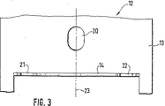
図1に示された、その他の部分は示されていない車両ブレーキ系の液圧式ユニット11を弾性的に支承するための装置10は、コンソール12を有しており、このコンソール12は、概略的にのみ図示したように、車両の車体に堅固に結合されている。コンソール12は、互いに直角に延びた2つの脚13,14を有しており、これらの脚にはユニット11が、ピン15,16によって貫通されたエラストマエレメント17,18を用いて支承されている。ユニット11の下側19に設けられたピン15は、長さの一部まで前記ユニットに押し込まれており、中空円筒状に形成されたエラストマエレメント17を貫通している。エラストマエレメントは、薄板成形部材として形成されたコンソール12の、下側19に対して平行に延びた第1の脚13に設けられた、卵形又は楕円形の長孔の形式の開口20に結合されている。コンソールの第1の脚13から直立した第2の脚14には、間隔を置いて配置された2つの切欠21,22が形成されており、これらの切欠は、この脚14の平面に対して直角に延びた平面23に対して対称的に位置しており、この平面23上において、ピン15と、長手方向軸線を備えた開口20の長孔とが延びている(図2及び図3)。両切欠21,22は、上方へ開放した、ほぼ円形の輪郭を有している。両切欠21,22の領域において第2の脚14の側面24,25には、図2に切欠22の周囲に概略的に示されているように、エンボス加工部26が設けられていてよい。両切欠21,22の数に一致して2つずつ設けられたピン16及びエラストマエレメント18は同じ構造を有する。両方の箇所に取り付けられる構成部材について以下に説明する。
【0010】
ピン16は、長手方向に波形が形成された押込みプラグ28を有しており、この押込みプラグ28を用いてピンはユニット11の収容孔29に相対回動不能に押込み座を用いて収容されている(図4)。実施例とは異なる形式では、押込みプラグ28にねじ山区分が設けられて、ピン16が螺合によってユニット11に取り付けられていることもできる。押込みプラグ28には、ピン16の、直径がより大きな皿状部30が接続しており、この皿状部30を用いてピンは下側19に対して直角に延びた端面31に軸方向に支持されている。皿状部30には、減径された区分32が形成されており、この区分32から、この区分よりも減径されたねじシャフト33が延びている。ピン16には、エラストマエレメント18と、フランジ35を備えたブシュ34と、ナット36とが被せ嵌められている。これらの構成部材は、コンソールの第2の脚14における、ユニット11のための取付け手段として働く構造群37を形成しており、この構造群37は、ユニットに取り付ける前に、図5に示したような形式で予備取付け可能である。
【0011】
ピン16に嵌合されたエラストマエレメント18は等しい直径の2つの端部区分38,39を有しており、これらの端部区分は、より小さな直径の中間区分40によって結合されている。この形状により、中空円筒状のエレメント18は、周囲を取り囲んだ環状溝41を有しており、この環状溝41の直径は、基本的に、コンソール12の第2の脚14における個々の切欠21,22の直径よりも所定の寸法だけ大きく、環状溝の幅は第2の脚の厚さよりも大きい。
【0012】
エラストマエレメント18は、予備取り付けされた状態においては、軸方向に圧迫されずにピン16に被せ嵌められている(図5)。エラストマエレメントは、端部区分38において、ピン16の、エラストマエレメントの内径に合致して嵌合した区分32と皿状部30とを包囲している。ピン16にはめ込まれたブシュ34は、区分32と同じ外径を有しており、エラストマエレメント18の他方の端部区分39に合致して貫通している。フランジ35はエラストマエレメント18の外径に合致されている。フランジ35を備えたブシュ34とナット36とは緊定手段を形成しており、この緊定手段によってエラストマエレメント18は軸方向に圧縮可能である(図4)。
【0013】
図5に示したように、区分39の軸方向長さに合致したブシュ34は、区分32に対して間隔を形成しており、この区分32は、皿状部30と共に、軸方向でエラストマエレメント18の端部区分38の長さに亘って延びている。これにより、エラストマエレメント18の圧迫されていない状態において、中間区分40に配属された、ピン16のねじシャフト33を包囲した環状ギャップ43が形成され、これにより、エラストマエレメント18は、図5に示した取付け状態において、中間区分40の領域において半径方向内方へ撓むことができる。
【0014】
液圧式ユニット11をコンソール12に取り付けるために、ピン15及び、ピン16と、エラストマエレメント18と、フランジ35を備えたブシュ34と、ナット36とから成る図5に示された2つの構造群37がユニット11にはめ込まれる。ユニット11の下側19に設けられたピン15に配属されたエラストマエレメント17は、ピンに被せ嵌められているか又は、既にコンソール12の第1の脚13における開口20にはめ込まれていることができる。このように完成されたユニット11は、図1に矢印45で示した取付け方向でコンソール12へ降ろされる。この場合、自由端部においてビード状の、周囲に沿って設けられたシール部を有することができるピン15は、エラストマエレメント17にはめ込まれる(又はピンに予め取り付けられたエラストマエレメントが脚13の開口20を貫通する)。同時に、ピン16と、エラストマエレメント18と、緊定手段34,35,36とから成るそれぞれの構造群37が、配属された、取付け方向とは反対方向に上方へ開放した切欠21,22にはめ込まれる。この場合、エラストマエレメント18に設けられた中間区分40は、切欠21,22の漏斗状の口を通過するときに半径方向内方へ変形させられる。コンソール12におけるユニット11の最終位置が達成されると、エラストマエレメント18の中間区分40の変形は、固有弾性によって大幅に解消される。
【0015】
次いで、それぞれのナット36が締め付けられ、これにより、フランジ35を備えたブシュ34はねじシャフト33上を長手方向に摺動し、エラストマエレメント18は、半径方向に拡開しながら軸方向で圧迫され、軸方向に圧縮される。軸方向の圧縮に基づき、液圧式ユニット11はコンソール12の第2の脚14に向かって摺動する。これと同時に、エラストマエレメント17は開口20内において長手方向軸線の方向に摺動するが、この場合、コンソール12の第2の脚13との相互形状による結合を失うことはない。
【0016】
ねじ締め行程は、ピン16の区分32にブシュ34が衝突することによって終了される。図4に示されたこの状態では、エラストマエレメント18の環状ギャップ43はピン16の区分32とブシュ34とによって完全に充填されている。エラストマエレメント18は次のように変形させられる。すなわち、円周の半分以上までがコンソール12の第2の脚14によって掴まれた中間区分40が半径方向内方へ押圧されながら切欠21,22に係合するようにである。これに対してエラストマエレメント18の両方の端部区分38,39は、軸方向に押圧されながら第2の脚14の両方の側面24,25に当て付けられる。エラストマエレメント18の軸方向圧迫によって、コンソール12の第2の脚14との摩擦による結合及び相互形状による結合が生ぜしめられ、この場合、エンボス加工部は補助的に作用する。取付け技術上安価に行われるコンソール12へのユニット11の弾性的な支承により、装置の妨害的な振動が車両の車体に伝達することが大幅に回避される。
【図面の簡単な説明】
【図1】 コンソールを用いて車両ブレーキ系の液圧式ユニットを弾性的に支承するための装置を側面図で示している。
【図2】 コンソールの区分を図1の矢印IIの方向で見た拡大図を示している。
【図3】 コンソールの区分を図2の矢印IIIの方向で見た平面図を示している。
【図4】 装置の軸方向に圧迫された固定手段を、図1のIV−IV線に沿って見た拡大された断面図を示している。
【図5】 図4に示した固定手段を示しているが、圧迫されていない構造群として示されている。
【符号の説明】
10 装置、 11 液圧式ユニット、 12 コンソール、 13,14 脚、 15,16 ピン、 17,18 エラストマエレメント、 19 下側、 20 開口、 21,22 切欠、 23 平面、 24,25 側面、 26 エンボス加工部、 28 押込みプラグ、 29 収容孔、 30 皿状部、 31 端面、 32 減径された区分、 33 ねじシャフト、 34 ブシュ、 35 フランジ、 36 ナット、 37 構造群、 38,39 端部区分、 40 中間区分、 41 環状溝、 43 環状ギャップ[0001]
The invention starts from an apparatus based on the superordinate concept part of claim 1.
[0002]
Such a device is already known (German Patent Application Publication No. 19724177), and such a device is arranged at a distance from each other and a web positioned below and projecting perpendicularly from the web. And a console with two legs. Each leg is formed with a support shell open upward. In contrast, the web is provided with an upward pin. The vehicle brake system hydraulic unit is fitted to the console from above. In this case, the pin engages with a notch provided on the lower side of the unit with a bush-like elastomer element disposed therebetween. On the other hand, a bush-like elastomer element is accommodated in the support shell of the leg, and this elastomer element is fixed to the two opposite sides of the device by screws. In order to position the device in the console, the bearing shell is bridged by a fastener on the open side, which is fastened to the console leg using a locking mesh. The console is attached to the vehicle body of the vehicle in the engine compartment of the vehicle.
[0003]
Advantages of the invention On the other hand, the device according to the invention with the features of claim 1 provides that the deformation of the respective hydraulic element and the console results in a mutual coupling and frictional coupling between the hydraulic unit and the console. Have advantages. This eliminates the need for a separate structural part for fixing the position of the unit.
[0004]
By means of the dependent claims, advantageous developments and improvements of the device according to claim 1 are provided.
[0005]
The arrangement of the device according to claim 2 provides a three-point support for the device, in which case the elastomer element housed in the second leg of the console can be assigned to the end face of the unit, This contributes to minimizing the required assembly space of the device in the vehicle.
[0006]
The dependent claims 3, 4 and 5 describe advantageous configurations for the elastomer elements and the fastening means.
[0007]
The structure of the invention according to claim 6 provides a group of structures that can be mounted and tested separately from the unit.
[0008]
Drawings Embodiments of the invention are shown in simplified form in the drawings and are described in more detail below. FIG. 1 shows a side view of a device for elastically supporting a hydraulic unit of a vehicle brake system using a console, and FIG. 2 shows a section of the console in the direction of arrow II in FIG. 3 shows an enlarged view, FIG. 3 shows a plan view of the console section in the direction of arrow III in FIG. 2, and FIG. 4 shows a diagram of the fixing means of the unit compressed in the axial direction. Fig. 5 shows an enlarged sectional view taken along line IV-IV of Fig. 1, and Fig. 5 shows the fixing means shown in Fig. 4, but is shown as an uncompressed structure group.
[0009]
Detailed description of the embodiment A
[0010]
The
[0011]
The
[0012]
The
[0013]
As shown in FIG. 5, the
[0014]
In order to attach the
[0015]
Each
[0016]
The screwing process is terminated by the impact of the
[Brief description of the drawings]
FIG. 1 shows a side view of a device for elastically supporting a hydraulic unit of a vehicle brake system using a console.
FIG. 2 shows an enlarged view of the console section as seen in the direction of arrow II in FIG.
FIG. 3 shows a plan view of the console sections as seen in the direction of arrow III in FIG. 2;
4 shows an enlarged cross-sectional view of the fixing means compressed in the axial direction of the device, taken along line IV-IV in FIG.
FIG. 5 shows the securing means shown in FIG. 4 but shown as an uncompressed group of structures.
[Explanation of symbols]
10 equipment, 11 hydraulic units, 12 consoles, 13, 14 legs, 15, 16 pins, 17, 18 elastomer elements, 19 lower side, 20 openings, 21, 22 notches, 23 planes, 24, 25 side surfaces, 26 embossing Part, 28 push plug, 29 receiving hole, 30 countersunk part, 31 end face, 32 reduced diameter section, 33 screw shaft, 34 bush, 35 flange, 36 nut, 37 structure group, 38, 39 end part section, 40 Middle section, 41 annular groove, 43 annular gap
Claims (5)
互いに直角に延びた2つの脚(13,14)を有するコンソール(12)が設けられており、該コンソールにユニット(11)が、ピン(15,16)によって貫通されたエラストマエレメント(17,18)を用いて支承されており、
ユニット(11)の取付け方向(45)に延びた第1のピン(15)が、取付け方向(45)に対して直角に延びた、コンソール(12)の第1の脚(13)に配属されており、
これに対して、コンソール(12)の第2の脚(14)が、第2の脚(14)の平面に対して直角に延びた軸線を備えたエラストマエレメント(18)を収容するための、取付け方向(45)とは反対方向に開放した少なくとも1つの切欠(21,22)を有している形式のものにおいて、
コンソール(12)の第2の脚(14)に配属された、中空円筒状のエラストマエレメント(18)が、減径された中間区分(40)を有しており、該中間区分が、コンソール(12)の第2の脚(14)の切欠(21,22)にはめ込まれており、
エラストマエレメント(18)の中間区分(40)が、円周の半分以上までコンソール(12)の第2の脚(14)によって取り囲まれており、
コンソール(12)の第2の脚(14)に配属されたエラストマエレメント(18)が、第2のピン(16)に配置された緊定手段(34,35,36)によって半径方向に拡開されかつ軸方向で圧縮され、
エラストマエレメント(18)が、中間区分(40)においては切欠(21,22)に押し付けられておりかつ、中間区分(40)の両側に隣接した端部区分(38,39)においては、コンソール(12)の第2の脚(14)の、切欠(21,22)を取り囲んだ両方の側面(24,25)に押し付けられており、
前記第2のピン(16)が、ユニット(11)に押し込まれているか又はねじ込まれておりかつユニット(11)に隣接して、エラストマエレメント(18)の内径にはまり込んだ区分(32)を有しており、該区分(32)から、より直径が小さなねじシャフト(33)が延びており、該ねじシャフトに緊定手段としてフランジ(35)を備えたブシュ(34)とナット(36)とが被せ嵌められており、
第2のピン(16)と、一方の端部区分(38)において第2のピン(16)のユニット側の区分(32)に被せ嵌められたエラストマエレメント(18)と、エラストマエレメント(18)の他方の端部区分(39)にはめ込まれた、フランジ(35)を備えたブシュ(34)と、ねじシャフト(33)にねじ嵌められたナット(36)とが、構造群(37)を形成しており、
該構造群(37)が、ユニット(11)に取り付ける前に、予備取付け可能であることを特徴とする、車両ブレーキ系の液圧式のユニットを車両に弾性的に支承するための装置。An apparatus (10) for elastically supporting a hydraulic unit (11) of a vehicle brake system on a vehicle,
A console (12) having two legs (13, 14) extending at right angles to each other is provided, and an elastomer element (17, 18) in which a unit (11) is penetrated by pins (15, 16). )
A first pin (15) extending in the mounting direction (45) of the unit (11) is assigned to a first leg (13) of the console (12) extending perpendicular to the mounting direction (45). And
In contrast, the second leg (14) of the console (12) accommodates an elastomer element (18) with an axis extending perpendicular to the plane of the second leg (14). In the type having at least one notch (21, 22) open in the direction opposite to the mounting direction (45),
A hollow cylindrical elastomeric element (18) assigned to the second leg (14) of the console (12) has a reduced diameter intermediate section (40) which is connected to the console ( 12) in the notch (21, 22) of the second leg (14) of 12),
The middle section (40) of the elastomer element (18) is surrounded by the second leg (14) of the console (12) to more than half of the circumference;
The elastomer element (18) assigned to the second leg (14) of the console (12) is radially expanded by the clamping means (34, 35, 36) arranged on the second pin (16). And axially compressed,
The elastomer element (18) is pressed against the notches (21, 22) in the intermediate section (40) and in the end sections (38, 39) adjacent to both sides of the intermediate section (40), the console ( 12) pressed against both sides (24, 25) of the second leg (14) surrounding the notches (21, 22);
A section (32) in which the second pin (16) is pushed or screwed into the unit (11) and is adjacent to the unit (11) and fits inside the inner diameter of the elastomer element (18). A screw shaft (33) having a smaller diameter extends from the section (32) and includes a bush (34) and a nut (36) provided with a flange (35) as a tightening means. And are fitted,
A second pin (16), an elastomer element (18) fitted over a unit side section (32) of the second pin (16) in one end section (38), and an elastomer element (18) A bushing (34) with a flange (35) fitted into the other end section (39) of the screw and a nut (36) screwed onto the screw shaft (33) assemble the structural group (37). Formed,
A device for elastically supporting a hydraulic unit of a vehicle brake system on a vehicle, characterized in that the structural group (37) can be pre-attached before being attached to the unit (11) .
Applications Claiming Priority (3)
| Application Number | Priority Date | Filing Date | Title |
|---|---|---|---|
| DE10036575.2 | 2000-07-27 | ||
| DE10036575A DE10036575A1 (en) | 2000-07-27 | 2000-07-27 | Device for the elastic mounting of a hydraulic unit of a vehicle brake system in a vehicle |
| PCT/DE2001/002265 WO2002010610A1 (en) | 2000-07-27 | 2001-06-19 | Device for the elastic mounting of a hydraulic unit in a motor vehicle braking system on a vehicle |
Publications (2)
| Publication Number | Publication Date |
|---|---|
| JP2004521276A JP2004521276A (en) | 2004-07-15 |
| JP4751006B2 true JP4751006B2 (en) | 2011-08-17 |
Family
ID=7650387
Family Applications (1)
| Application Number | Title | Priority Date | Filing Date |
|---|---|---|---|
| JP2002516504A Expired - Lifetime JP4751006B2 (en) | 2000-07-27 | 2001-06-19 | Device for elastically supporting a hydraulic unit of a vehicle brake system on a vehicle |
Country Status (7)
| Country | Link |
|---|---|
| US (1) | US7510163B2 (en) |
| EP (1) | EP1307667B1 (en) |
| JP (1) | JP4751006B2 (en) |
| KR (1) | KR100760837B1 (en) |
| DE (2) | DE10036575A1 (en) |
| HU (1) | HU223233B1 (en) |
| WO (1) | WO2002010610A1 (en) |
Cited By (1)
| Publication number | Priority date | Publication date | Assignee | Title |
|---|---|---|---|---|
| CN115163744A (en) * | 2022-09-07 | 2022-10-11 | 万向钱潮股份公司 | Fixed damping device and mounting method thereof |
Families Citing this family (55)
| Publication number | Priority date | Publication date | Assignee | Title |
|---|---|---|---|---|
| DE10036575A1 (en) | 2000-07-27 | 2002-02-07 | Bosch Gmbh Robert | Device for the elastic mounting of a hydraulic unit of a vehicle brake system in a vehicle |
| JP3720278B2 (en) * | 2001-06-13 | 2005-11-24 | 株式会社日立製作所 | Brake unit hydraulic unit support structure |
| GB2392969A (en) * | 2002-09-12 | 2004-03-17 | First Int Computer Inc | Resilient mounting for data storage device |
| DE10245797B4 (en) * | 2002-10-01 | 2004-09-16 | Robert Bosch Gmbh | Device for the vibration-damping arrangement of a unit and unit equipped with such devices |
| JP2005088691A (en) * | 2003-09-16 | 2005-04-07 | Advics:Kk | Brake unit |
| US7552901B2 (en) * | 2004-09-02 | 2009-06-30 | United Parcel Service Of America, Inc. | Rapid exchange system for testing wireless networks |
| JP4738874B2 (en) * | 2005-04-15 | 2011-08-03 | トヨタ自動車株式会社 | Support device for vehicle-mounted object |
| JP4841884B2 (en) * | 2005-07-19 | 2011-12-21 | 日立オートモティブシステムズ株式会社 | Brake unit |
| DE102005042241B4 (en) * | 2005-09-05 | 2017-08-03 | Voith Turbo Gmbh & Co. Kg | Storage system for driven by a prime mover pump units |
| US7407234B1 (en) * | 2005-09-17 | 2008-08-05 | Robert Bosch Gmbh | Manual assembly to ABS/TCS/ESP hydraulic units |
| DE102005046631A1 (en) | 2005-09-29 | 2007-04-05 | Robert Bosch Gmbh | Unit`s e.g. hydraulic unit, oscillation damping suspension device, has clamping unit transferred from basic position to clamping position by manual operation, axially movable and guided in armature and locked with armature in both positions |
| DE102005047356A1 (en) * | 2005-10-04 | 2007-04-05 | Robert Bosch Gmbh | Holding device for attachment of motor vehicle assembly, has nut, bolt, damping element premounted as advancing element group which is insertable in prepared bore hole in housing of motor vehicle assembly |
| JP5238141B2 (en) * | 2006-04-25 | 2013-07-17 | トヨタ自動車株式会社 | Support structure for hydraulic unit |
| JP4724614B2 (en) * | 2006-07-13 | 2011-07-13 | 株式会社ブリヂストン | Vibration isolator |
| DE102007020928B4 (en) * | 2007-05-04 | 2014-05-22 | GM Global Technology Operations LLC (n. d. Ges. d. Staates Delaware) | Holder for attaching a vehicle module |
| JP2009074386A (en) * | 2007-09-19 | 2009-04-09 | Sanden Corp | Compressor |
| US8746810B2 (en) * | 2007-11-02 | 2014-06-10 | Bosch Corporation | Brake fluid pressure control device |
| US8226066B2 (en) * | 2007-11-27 | 2012-07-24 | Lord Corporation | Center-bonded isolation mounting assembly |
| US20090272872A1 (en) * | 2008-04-30 | 2009-11-05 | Hoffman Loren D | Mounting assembly to secure a grommet to a compressor foot including dimpled slot |
| CN101626668B (en) * | 2008-07-08 | 2012-09-19 | 鸿富锦精密工业(深圳)有限公司 | Electronic equipment component and fixing device thereof |
| US8132640B2 (en) * | 2008-08-07 | 2012-03-13 | Honda Motor Co., Ltd. | Frangible mount for a vehicle differential |
| JP5584478B2 (en) * | 2009-04-30 | 2014-09-03 | ボッシュ株式会社 | Hydraulic unit support structure |
| TWM370915U (en) * | 2009-07-03 | 2009-12-11 | Multi Expander Technology Inc | Shock absorber and shock absorbing structure |
| DE102009029569A1 (en) | 2009-09-18 | 2011-03-31 | Robert Bosch Gmbh | Device for the vibration-damping mounting of a fluid aggregate and associated fluid aggregate |
| DE102010014804B4 (en) * | 2010-04-07 | 2024-02-15 | Dr. Ing. H.C. F. Porsche Aktiengesellschaft | Arrangement for storing an assembly on a motor vehicle body |
| US20130075572A1 (en) * | 2010-06-18 | 2013-03-28 | Suzuki Motor Corporation | Structure for mounting electric vacuum pump |
| KR101184281B1 (en) * | 2010-11-30 | 2012-09-21 | 기아자동차주식회사 | Roll-rod for vehicle |
| WO2012089508A1 (en) * | 2010-12-30 | 2012-07-05 | Arcelik Anonim Sirketi | Household appliance comprising a knob which operates silently |
| DE102011002807A1 (en) | 2011-01-18 | 2012-07-19 | Robert Bosch Gmbh | Arrangement for assembling vehicle unit i.e. fluid assembly, of vehicle brake system e.g. anti-skid system, has locking mechanism implementing holding function for vehicle unit and connecting vehicle unit with vehicle-side holding device |
| WO2012115622A1 (en) * | 2011-02-22 | 2012-08-30 | International Truck Intellectual Property Company, Llc | Hanger assembly |
| JP5854845B2 (en) * | 2012-01-10 | 2016-02-09 | 本田技研工業株式会社 | Anti-vibration support structure |
| DE102012203070A1 (en) | 2012-02-29 | 2013-08-29 | Continental Teves Ag & Co. Ohg | Hydraulic power unit for brake system of motor car, has electric motor which is attached at the side surface of the holding unit by locking bolt provided in the region of hydraulic power unit holder |
| US8936228B2 (en) | 2012-05-02 | 2015-01-20 | Caterpillar Inc. | Load isolation bracket |
| US8919725B2 (en) | 2012-05-23 | 2014-12-30 | Caterpillar Inc. | Exterior mounting apparatus for interior component |
| US8956069B2 (en) * | 2012-05-25 | 2015-02-17 | Robert Bosch Gmbh | Tool-free connector and mounting arrangement |
| US9097269B2 (en) * | 2012-06-04 | 2015-08-04 | Fisher Controls International, Llc | Bracket assemblies for use with actuators |
| DE102012108737A1 (en) | 2012-09-18 | 2014-04-03 | Dr. Ing. H.C. F. Porsche Aktiengesellschaft | Valve block structure for vehicle e.g. motor car, has retaining plate that is connected with groove which is provided at circumferential region of resilient sleeve portions comprising recesses at which projection portions are connected |
| US20140115868A1 (en) * | 2012-10-29 | 2014-05-01 | Gregory Ruhlander | Coupling System to Reduce Vibration |
| DE102013202323A1 (en) | 2013-02-13 | 2014-08-14 | Continental Teves Ag & Co. Ohg | Hydraulic aggregate for motor car brake assembly, has receiving body opening hydrastic break transmitter terminal from flange, where pumping bore is traversed by through hole and extends from hydrastic break transmitter terminal to flange |
| US9790894B2 (en) * | 2013-03-19 | 2017-10-17 | Hamilton Sundstrand Corporation | Inner housing assembly including retention slots |
| TWI508646B (en) * | 2013-04-23 | 2015-11-11 | Hon Hai Prec Ind Co Ltd | Fixing device and plate assembly |
| JP5753225B2 (en) * | 2013-06-17 | 2015-07-22 | 住友理工株式会社 | Vibration isolator |
| DE102013221945B4 (en) * | 2013-10-29 | 2019-04-04 | Bayerische Motoren Werke Aktiengesellschaft | Vehicle with an electric refrigerant compressor |
| US9945701B2 (en) | 2015-07-17 | 2018-04-17 | Fisher Controls International Llc | Actuator bracket having a sensor |
| US9807993B2 (en) * | 2015-08-04 | 2017-11-07 | Darryl Montoya | System and apparatus for the storage and display of fishing lures |
| JP6666177B2 (en) * | 2016-03-15 | 2020-03-13 | 本田技研工業株式会社 | Engine driven work machine |
| US20170328425A1 (en) * | 2016-05-10 | 2017-11-16 | Hyperloop Technologies, Inc. | Friction braking system |
| DE102016007911A1 (en) * | 2016-06-30 | 2018-01-04 | Mann+Hummel Gmbh | Vibration decoupler and vibration-decoupled component arrangement |
| US10111557B2 (en) * | 2016-07-27 | 2018-10-30 | Capbran Holdings, Llc | Food processor dampen system |
| US10502308B2 (en) | 2016-12-22 | 2019-12-10 | Polaris Industries Inc. | Driveline for powersports vehicle |
| DE102018202926A1 (en) * | 2018-02-27 | 2019-08-29 | Aktiebolaget Skf | Actuator with a threaded spindle and plastic element |
| JP2019182182A (en) * | 2018-04-10 | 2019-10-24 | ロベルト・ボッシュ・ゲゼルシャフト・ミト・ベシュレンクテル・ハフツングRobert Bosch Gmbh | Brake fluid pressure control device |
| US10926720B2 (en) * | 2018-09-19 | 2021-02-23 | Ford Global Technologies, Llc | Rubber spool grommets for assembly to vehicle |
| KR102654461B1 (en) * | 2019-09-05 | 2024-04-03 | 현대자동차 주식회사 | Compressor mounting device for vehicle |
| DE102021203611A1 (en) | 2021-04-13 | 2022-10-13 | Psa Automobiles Sa | Bracket for an ESC module |
Citations (4)
| Publication number | Priority date | Publication date | Assignee | Title |
|---|---|---|---|---|
| JPS5054753A (en) * | 1973-09-17 | 1975-05-14 | ||
| JPS63101350A (en) * | 1986-10-17 | 1988-05-06 | Sanyo Chem Ind Ltd | Production of acrylates |
| JPH04118326A (en) * | 1990-09-07 | 1992-04-20 | Daihatsu Motor Co Ltd | Supporting device for fuel filter in engine for vehicle |
| JP2000168529A (en) * | 1998-12-01 | 2000-06-20 | Nissin Kogyo Co Ltd | Brake hydraulic pressure control device for vehicle |
Family Cites Families (30)
| Publication number | Priority date | Publication date | Assignee | Title |
|---|---|---|---|---|
| US1778992A (en) * | 1929-01-26 | 1930-10-21 | Wagner Electric Corp | Motor mounting |
| GB414819A (en) | 1933-03-24 | 1934-08-16 | Gen Electric Co Ltd | Improvements in or relating to means for mounting electrical apparatus |
| US2662988A (en) * | 1948-07-15 | 1953-12-15 | Gen Electric | Base for motors |
| US2810536A (en) * | 1954-12-07 | 1957-10-22 | Gen Electric | Cradle type base for rotatable machinery |
| US2893722A (en) * | 1957-09-06 | 1959-07-07 | Lord Mfg Co | Resilient mounting |
| FR1260978A (en) | 1960-06-18 | 1961-05-12 | Goodrich Co B F | Elastic support |
| US3128999A (en) * | 1962-09-17 | 1964-04-14 | Lord Mfg Co | Resilient mounting |
| US3350042A (en) | 1965-10-11 | 1967-10-31 | Clevite Corp | Corrugated resilient mount |
| US3756551A (en) * | 1971-10-27 | 1973-09-04 | Lord Corp | Anti-vibration support |
| JPS5054753U (en) * | 1973-09-21 | 1975-05-24 | ||
| US3895408A (en) * | 1974-01-30 | 1975-07-22 | Charles J Leingang | Resilient mounting |
| US4067531A (en) * | 1976-07-22 | 1978-01-10 | Derre & Company | Vibration isolation and sealing gasket |
| USRE31525E (en) * | 1977-05-25 | 1984-02-28 | General Electric Company | Adaptable resilient motor mounting |
| US4521004A (en) * | 1982-10-27 | 1985-06-04 | Caldwell William F | Vibration-isolating mounting with load-directing chamfer |
| JPS63101350U (en) * | 1986-12-23 | 1988-07-01 | ||
| US5222374A (en) * | 1990-05-11 | 1993-06-29 | Whirlpool Corporation | Assembly method and construction for a room air conditioner |
| DE4317467A1 (en) * | 1993-05-26 | 1994-12-01 | Bosch Gmbh Robert | Vibration-damping arrangement of a hydraulic unit of a slip-controlled brake system |
| US5464187A (en) * | 1993-10-06 | 1995-11-07 | Kelsey-Hayes Company | Mounting bracket for an anti-lock brake/traction control system control valve |
| DE4403466A1 (en) | 1994-02-04 | 1995-08-10 | Teves Gmbh Alfred | Pressure control device for slip-controlled hydraulic brake systems |
| KR970001879B1 (en) * | 1994-03-30 | 1997-02-18 | 닛신 고오교오 가부시끼가이샤 | Anti-lock brake control method for a vehicle |
| FR2727478B1 (en) * | 1994-11-30 | 1997-04-04 | Valeo Systemes Dessuyage | DEVICE FOR FIXING AN ELEMENT ON THE BODY OF A MOTOR VEHICLE |
| US5722631A (en) * | 1995-09-15 | 1998-03-03 | Lord Corporation | Single-piece mount with split metal plates |
| AU4481197A (en) | 1996-09-17 | 1998-04-14 | Kelsey-Hayes Company | Mounting arrangement for supporting a hydraulic control unit of a vehicular braking system |
| DE19724177A1 (en) | 1997-06-09 | 1998-12-10 | Bosch Gmbh Robert | Elastic mounting of a hydraulic unit in a vehicle brake system |
| US6029942A (en) * | 1998-03-24 | 2000-02-29 | Carrier Corporation | Simplified compressor mount with self forming grommet |
| DE19963757B4 (en) * | 1999-12-30 | 2012-06-14 | Robert Bosch Gmbh | Elastic mounting of a particular electro-hydraulic unit of a vehicle brake system |
| US6471179B1 (en) * | 2000-04-28 | 2002-10-29 | Freudenberg-Nok General Partnership | Isolation mount |
| DE10036575A1 (en) | 2000-07-27 | 2002-02-07 | Bosch Gmbh Robert | Device for the elastic mounting of a hydraulic unit of a vehicle brake system in a vehicle |
| US6557815B1 (en) * | 2000-12-05 | 2003-05-06 | University Of Northern Iowa Research Foundation | Universal mounting bracket for laser targeting and feedback system |
| JP3720278B2 (en) * | 2001-06-13 | 2005-11-24 | 株式会社日立製作所 | Brake unit hydraulic unit support structure |
-
2000
- 2000-07-27 DE DE10036575A patent/DE10036575A1/en not_active Withdrawn
-
2001
- 2001-06-19 KR KR1020037001057A patent/KR100760837B1/en active IP Right Grant
- 2001-06-19 US US10/333,718 patent/US7510163B2/en not_active Expired - Lifetime
- 2001-06-19 DE DE50106911T patent/DE50106911D1/en not_active Expired - Lifetime
- 2001-06-19 HU HU0301468A patent/HU223233B1/en not_active IP Right Cessation
- 2001-06-19 JP JP2002516504A patent/JP4751006B2/en not_active Expired - Lifetime
- 2001-06-19 WO PCT/DE2001/002265 patent/WO2002010610A1/en active IP Right Grant
- 2001-06-19 EP EP01953111A patent/EP1307667B1/en not_active Expired - Lifetime
Patent Citations (4)
| Publication number | Priority date | Publication date | Assignee | Title |
|---|---|---|---|---|
| JPS5054753A (en) * | 1973-09-17 | 1975-05-14 | ||
| JPS63101350A (en) * | 1986-10-17 | 1988-05-06 | Sanyo Chem Ind Ltd | Production of acrylates |
| JPH04118326A (en) * | 1990-09-07 | 1992-04-20 | Daihatsu Motor Co Ltd | Supporting device for fuel filter in engine for vehicle |
| JP2000168529A (en) * | 1998-12-01 | 2000-06-20 | Nissin Kogyo Co Ltd | Brake hydraulic pressure control device for vehicle |
Cited By (2)
| Publication number | Priority date | Publication date | Assignee | Title |
|---|---|---|---|---|
| CN115163744A (en) * | 2022-09-07 | 2022-10-11 | 万向钱潮股份公司 | Fixed damping device and mounting method thereof |
| CN115163744B (en) * | 2022-09-07 | 2024-01-16 | 万向钱潮股份公司 | Fixed damping device and installation method thereof |
Also Published As
| Publication number | Publication date |
|---|---|
| WO2002010610A1 (en) | 2002-02-07 |
| US20030155809A1 (en) | 2003-08-21 |
| US7510163B2 (en) | 2009-03-31 |
| HU223233B1 (en) | 2004-04-28 |
| KR20030019611A (en) | 2003-03-06 |
| JP2004521276A (en) | 2004-07-15 |
| HUP0301468A2 (en) | 2003-08-28 |
| EP1307667A1 (en) | 2003-05-07 |
| KR100760837B1 (en) | 2007-09-27 |
| DE50106911D1 (en) | 2005-09-01 |
| EP1307667B1 (en) | 2005-07-27 |
| DE10036575A1 (en) | 2002-02-07 |
Similar Documents
| Publication | Publication Date | Title |
|---|---|---|
| JP4751006B2 (en) | Device for elastically supporting a hydraulic unit of a vehicle brake system on a vehicle | |
| US6321890B1 (en) | Vibration reducing system for automotive vehicle | |
| US5002243A (en) | Plastic holding device with noise dampening | |
| KR101098780B1 (en) | Device for suspending a unit such that vibrations are damped | |
| JP5296692B2 (en) | Work insulation assembly | |
| US6276652B1 (en) | Securing component | |
| JP6964140B2 (en) | Grommet | |
| US20070057422A1 (en) | Device for vibration-damping disposition of a unit, and unit equipped with such devices | |
| KR20090007196A (en) | Fixing structure of article and hinge device | |
| US5865067A (en) | Pedal mounting structure and method of installing a pedal in an automotive vehicle | |
| KR100335387B1 (en) | Mounting structure of motor for maintaining gab between rotor and bracket | |
| US11001306B2 (en) | Isolation mount assembly | |
| JP2005147226A (en) | Fastening member with damping function, and vibration control device using its fastening member | |
| JP3653538B2 (en) | Screw mounting structure of mounted body and screwing method of mounted body | |
| KR20010086284A (en) | Elastic bearing of a electrohydraulic unit of a brake system of a vehicle | |
| JPH08326811A (en) | Vibration control device | |
| KR102620418B1 (en) | Mounting Socket for Vehicle Cables | |
| KR100205897B1 (en) | Wire-ring fastening of clamp | |
| KR100235042B1 (en) | Oil pipe and cable fixing clip for vehicle | |
| GB2305767A (en) | Drum sensor mounting | |
| JP3324511B2 (en) | Fixing structure of electrical junction box | |
| JP2000018326A (en) | Vibration isolating rubber structure | |
| KR0122426Y1 (en) | Device for fixing compressor | |
| KR100199737B1 (en) | Binding device of accelerator pedal | |
| JP2002317852A (en) | Base mounting device, hydraulic unit for vehicle having base mounting device, and base mounting method |
Legal Events
| Date | Code | Title | Description |
|---|---|---|---|
| A621 | Written request for application examination |
Free format text: JAPANESE INTERMEDIATE CODE: A621 Effective date: 20080617 |
|
| A977 | Report on retrieval |
Free format text: JAPANESE INTERMEDIATE CODE: A971007 Effective date: 20100624 |
|
| A131 | Notification of reasons for refusal |
Free format text: JAPANESE INTERMEDIATE CODE: A131 Effective date: 20100707 |
|
| A601 | Written request for extension of time |
Free format text: JAPANESE INTERMEDIATE CODE: A601 Effective date: 20101007 |
|
| A602 | Written permission of extension of time |
Free format text: JAPANESE INTERMEDIATE CODE: A602 Effective date: 20101018 |
|
| A601 | Written request for extension of time |
Free format text: JAPANESE INTERMEDIATE CODE: A601 Effective date: 20101108 |
|
| A602 | Written permission of extension of time |
Free format text: JAPANESE INTERMEDIATE CODE: A602 Effective date: 20101115 |
|
| A601 | Written request for extension of time |
Free format text: JAPANESE INTERMEDIATE CODE: A601 Effective date: 20101207 |
|
| A602 | Written permission of extension of time |
Free format text: JAPANESE INTERMEDIATE CODE: A602 Effective date: 20101214 |
|
| A521 | Written amendment |
Free format text: JAPANESE INTERMEDIATE CODE: A523 Effective date: 20110107 |
|
| TRDD | Decision of grant or rejection written | ||
| A01 | Written decision to grant a patent or to grant a registration (utility model) |
Free format text: JAPANESE INTERMEDIATE CODE: A01 Effective date: 20110421 |
|
| A61 | First payment of annual fees (during grant procedure) |
Free format text: JAPANESE INTERMEDIATE CODE: A61 Effective date: 20110520 |
|
| R150 | Certificate of patent or registration of utility model |
Ref document number: 4751006 Country of ref document: JP Free format text: JAPANESE INTERMEDIATE CODE: R150 Free format text: JAPANESE INTERMEDIATE CODE: R150 |
|
| FPAY | Renewal fee payment (event date is renewal date of database) |
Free format text: PAYMENT UNTIL: 20140527 Year of fee payment: 3 |
|
| R250 | Receipt of annual fees |
Free format text: JAPANESE INTERMEDIATE CODE: R250 |
|
| R250 | Receipt of annual fees |
Free format text: JAPANESE INTERMEDIATE CODE: R250 |
|
| R250 | Receipt of annual fees |
Free format text: JAPANESE INTERMEDIATE CODE: R250 |
|
| R250 | Receipt of annual fees |
Free format text: JAPANESE INTERMEDIATE CODE: R250 |
|
| R250 | Receipt of annual fees |
Free format text: JAPANESE INTERMEDIATE CODE: R250 |
|
| R250 | Receipt of annual fees |
Free format text: JAPANESE INTERMEDIATE CODE: R250 |
|
| R250 | Receipt of annual fees |
Free format text: JAPANESE INTERMEDIATE CODE: R250 |
|
| R250 | Receipt of annual fees |
Free format text: JAPANESE INTERMEDIATE CODE: R250 |
|
| EXPY | Cancellation because of completion of term |