JP4726434B2 - Electrical connector for pressure sensor stem - Google Patents
Electrical connector for pressure sensor stem Download PDFInfo
- Publication number
- JP4726434B2 JP4726434B2 JP2004157525A JP2004157525A JP4726434B2 JP 4726434 B2 JP4726434 B2 JP 4726434B2 JP 2004157525 A JP2004157525 A JP 2004157525A JP 2004157525 A JP2004157525 A JP 2004157525A JP 4726434 B2 JP4726434 B2 JP 4726434B2
- Authority
- JP
- Japan
- Prior art keywords
- pressure sensor
- electrical connector
- base plate
- stem
- protective wall
- Prior art date
- Legal status (The legal status is an assumption and is not a legal conclusion. Google has not performed a legal analysis and makes no representation as to the accuracy of the status listed.)
- Expired - Lifetime
Links
- 230000001681 protective effect Effects 0.000 claims description 31
- 239000002775 capsule Substances 0.000 claims description 25
- 230000002093 peripheral effect Effects 0.000 claims description 13
- 238000004382 potting Methods 0.000 claims description 9
- 150000001875 compounds Chemical class 0.000 claims description 3
- 239000012530 fluid Substances 0.000 description 6
- 238000005304 joining Methods 0.000 description 4
- 238000004519 manufacturing process Methods 0.000 description 4
- 239000002184 metal Substances 0.000 description 4
- 238000005452 bending Methods 0.000 description 3
- 239000000463 material Substances 0.000 description 3
- 238000002347 injection Methods 0.000 description 2
- 239000007924 injection Substances 0.000 description 2
- 238000000465 moulding Methods 0.000 description 2
- 239000000088 plastic resin Substances 0.000 description 2
- 229910052594 sapphire Inorganic materials 0.000 description 2
- 239000010980 sapphire Substances 0.000 description 2
- VYPSYNLAJGMNEJ-UHFFFAOYSA-N Silicium dioxide Chemical compound O=[Si]=O VYPSYNLAJGMNEJ-UHFFFAOYSA-N 0.000 description 1
- PNEYBMLMFCGWSK-UHFFFAOYSA-N aluminium oxide Inorganic materials [O-2].[O-2].[O-2].[Al+3].[Al+3] PNEYBMLMFCGWSK-UHFFFAOYSA-N 0.000 description 1
- 239000012141 concentrate Substances 0.000 description 1
- 230000009977 dual effect Effects 0.000 description 1
- 230000002452 interceptive effect Effects 0.000 description 1
- WABPQHHGFIMREM-UHFFFAOYSA-N lead(0) Chemical compound [Pb] WABPQHHGFIMREM-UHFFFAOYSA-N 0.000 description 1
- 239000002991 molded plastic Substances 0.000 description 1
- 230000000149 penetrating effect Effects 0.000 description 1
- 239000011347 resin Substances 0.000 description 1
- 229920005989 resin Polymers 0.000 description 1
- 230000035939 shock Effects 0.000 description 1
- 229910052710 silicon Inorganic materials 0.000 description 1
- 239000010703 silicon Substances 0.000 description 1
- 229910000679 solder Inorganic materials 0.000 description 1
Images


Classifications
-
- G—PHYSICS
- G01—MEASURING; TESTING
- G01L—MEASURING FORCE, STRESS, TORQUE, WORK, MECHANICAL POWER, MECHANICAL EFFICIENCY, OR FLUID PRESSURE
- G01L19/00—Details of, or accessories for, apparatus for measuring steady or quasi-steady pressure of a fluent medium insofar as such details or accessories are not special to particular types of pressure gauges
- G01L19/0061—Electrical connection means
- G01L19/0084—Electrical connection means to the outside of the housing
-
- H—ELECTRICITY
- H01—ELECTRIC ELEMENTS
- H01R—ELECTRICALLY-CONDUCTIVE CONNECTIONS; STRUCTURAL ASSOCIATIONS OF A PLURALITY OF MUTUALLY-INSULATED ELECTRICAL CONNECTING ELEMENTS; COUPLING DEVICES; CURRENT COLLECTORS
- H01R13/00—Details of coupling devices of the kinds covered by groups H01R12/70 or H01R24/00 - H01R33/00
- H01R13/66—Structural association with built-in electrical component
- H01R13/665—Structural association with built-in electrical component with built-in electronic circuit
- H01R13/6683—Structural association with built-in electrical component with built-in electronic circuit with built-in sensor
-
- H—ELECTRICITY
- H01—ELECTRIC ELEMENTS
- H01R—ELECTRICALLY-CONDUCTIVE CONNECTIONS; STRUCTURAL ASSOCIATIONS OF A PLURALITY OF MUTUALLY-INSULATED ELECTRICAL CONNECTING ELEMENTS; COUPLING DEVICES; CURRENT COLLECTORS
- H01R12/00—Structural associations of a plurality of mutually-insulated electrical connecting elements, specially adapted for printed circuits, e.g. printed circuit boards [PCB], flat or ribbon cables, or like generally planar structures, e.g. terminal strips, terminal blocks; Coupling devices specially adapted for printed circuits, flat or ribbon cables, or like generally planar structures; Terminals specially adapted for contact with, or insertion into, printed circuits, flat or ribbon cables, or like generally planar structures
- H01R12/70—Coupling devices
- H01R12/71—Coupling devices for rigid printing circuits or like structures
- H01R12/712—Coupling devices for rigid printing circuits or like structures co-operating with the surface of the printed circuit or with a coupling device exclusively provided on the surface of the printed circuit
- H01R12/714—Coupling devices for rigid printing circuits or like structures co-operating with the surface of the printed circuit or with a coupling device exclusively provided on the surface of the printed circuit with contacts abutting directly the printed circuit; Button contacts therefore provided on the printed circuit
-
- H—ELECTRICITY
- H01—ELECTRIC ELEMENTS
- H01R—ELECTRICALLY-CONDUCTIVE CONNECTIONS; STRUCTURAL ASSOCIATIONS OF A PLURALITY OF MUTUALLY-INSULATED ELECTRICAL CONNECTING ELEMENTS; COUPLING DEVICES; CURRENT COLLECTORS
- H01R13/00—Details of coupling devices of the kinds covered by groups H01R12/70 or H01R24/00 - H01R33/00
- H01R13/46—Bases; Cases
- H01R13/502—Bases; Cases composed of different pieces
- H01R13/504—Bases; Cases composed of different pieces different pieces being moulded, cemented, welded, e.g. ultrasonic, or swaged together
-
- H—ELECTRICITY
- H01—ELECTRIC ELEMENTS
- H01R—ELECTRICALLY-CONDUCTIVE CONNECTIONS; STRUCTURAL ASSOCIATIONS OF A PLURALITY OF MUTUALLY-INSULATED ELECTRICAL CONNECTING ELEMENTS; COUPLING DEVICES; CURRENT COLLECTORS
- H01R13/00—Details of coupling devices of the kinds covered by groups H01R12/70 or H01R24/00 - H01R33/00
- H01R13/648—Protective earth or shield arrangements on coupling devices, e.g. anti-static shielding
- H01R13/658—High frequency shielding arrangements, e.g. against EMI [Electro-Magnetic Interference] or EMP [Electro-Magnetic Pulse]
- H01R13/6591—Specific features or arrangements of connection of shield to conductive members
- H01R13/6594—Specific features or arrangements of connection of shield to conductive members the shield being mounted on a PCB and connected to conductive members
- H01R13/6595—Specific features or arrangements of connection of shield to conductive members the shield being mounted on a PCB and connected to conductive members with separate members fixing the shield to the PCB
Landscapes
- Physics & Mathematics (AREA)
- General Physics & Mathematics (AREA)
- Engineering & Computer Science (AREA)
- Microelectronics & Electronic Packaging (AREA)
- Measuring Fluid Pressure (AREA)
- Details Of Connecting Devices For Male And Female Coupling (AREA)
Description
本発明は流体内の圧力感知に使用するための圧力センサに関する。特に、本発明は圧力センサ構成部品用の電気コネクタに関する。 The present invention relates to a pressure sensor for use in sensing pressure in a fluid. In particular, the present invention relates to electrical connectors for pressure sensor components.
圧力、温度、流量、およびpH等の、流体のパラメータを感知して、その感知された流体のパラメータ値を制御システムなど遠隔位置に送信するために、工業用送信機が使用される。これらの送信機は、その内側の圧力センサカプセル内に取り付けられる超小型圧力センサを含むことがある。この種の圧力センサは、接合用の電気接触パッドへのアクセスに備えるため、センサカプセルから突き出すセンサステムを有することがある。 Industrial transmitters are used to sense fluid parameters, such as pressure, temperature, flow rate, and pH, and transmit the sensed fluid parameter values to a remote location, such as a control system. These transmitters may include a micro pressure sensor that is mounted within a pressure sensor capsule inside it. This type of pressure sensor may have a sensor stem that protrudes from the sensor capsule to provide access to the electrical contact pads for bonding.
このセンサステムは一般的にサファイヤなどの脆い材料で形成されているので、送信機の製造中に工具その他の物との接触によって簡単に破損する。電気接触パッドに接合される接合線も非常に繊細であるので、接続点で破損しやすい。 Since this sensor stem is typically made of a brittle material such as sapphire, it is easily broken by contact with tools and other objects during the manufacture of the transmitter. Since the joining line joined to the electric contact pad is also very delicate, it is easily damaged at the connection point.
センサステム上の電気接触パッドから接合線への、簡単で信頼性のある電気コネクタの構成(arrangement)が必要とされている。この構成はまたセンサステムを破損から保護する。 There is a need for a simple and reliable electrical connector arrangement from the electrical contact pads on the sensor stem to the bond line. This configuration also protects the sensor stem from damage.
圧力センサカプセルから突き出す圧力センサステムを保護する電気コネクタを開示する。電気コネクタはそこを貫通する中央孔を有する台板を含む。 An electrical connector for protecting a pressure sensor stem protruding from a pressure sensor capsule is disclosed. The electrical connector includes a base plate having a central hole therethrough.
電気コネクタはまた前記台板につながる周壁を含む。周壁は台板より下に張り出ている。周壁は、圧力センサステムが前記中央孔を貫通して台板より上に突き出た時に、圧力センサカプセルに摺動可能に係合するように形成される。 The electrical connector also includes a peripheral wall connected to the base plate. The peripheral wall projects below the base plate. The peripheral wall is formed to slidably engage the pressure sensor capsule when the pressure sensor stem passes through the central hole and protrudes above the base plate.
電気コネクタは、前記台板につながる保護壁を含む。保護壁は圧力センサステムより上に突き出ている。電気コネクタが圧力センサカプセル上の所定位置にある場合、保護壁は圧力センサステムを保護する。保護壁内のリードフレームは圧力センサステム上のセンサ接触パッドに対する電気接続を提供する。また、保護壁は、圧力センサステムの周りにポッティング空洞を形成し、このポッティング空洞はポッティングコンパウンドの充填用に形作られる。更に、圧力センサステムがセンサの電気接触パッドを有し、保護壁がセンサの接触パッドの列に沿ったスロットを備えている。 The electrical connector includes a protective wall connected to the base plate. The protective wall protrudes above the pressure sensor stem. The protective wall protects the pressure sensor stem when the electrical connector is in place on the pressure sensor capsule. A lead frame in the protective wall provides an electrical connection to a sensor contact pad on the pressure sensor stem. The protective wall also forms a potting cavity around the pressure sensor stem that is shaped for filling the potting compound. In addition, the pressure sensor stem has electrical contact pads for the sensor, and the protective wall includes slots along the rows of sensor contact pads.
以下に示す実施形態において、電気コネクタは圧力センサカプセルの一端上に摺動するように形成された周壁と、脆い圧力センサステムより上にはみ出るように形成された保護壁とを有しており、該保護壁は操作中に外部の物体に接触して破損を受けることから圧力センサステムを保護する。前記周壁と保護壁は台板で一緒につながっていて、圧力センサカプセルに正しく整列するのを確実にする正のストッパを提供する。保護壁内のリードフレームは圧力センサステム上のセンサ接触パッドへの電気接続を提供する。電気コネクタは、好ましくは射出成型プラスチック樹脂によって形成され、RFI/EMIシールドの役割を果たす金属インサート(metal insert)を含む。典型的な圧力センサカプセルの構成を図1に関して以下に説明し、典型的な電気コネクタの構成を図2〜7に関して以下に説明する。 In the embodiment shown below, the electrical connector has a peripheral wall formed so as to slide on one end of the pressure sensor capsule, and a protective wall formed so as to protrude above the brittle pressure sensor stem, The protective wall protects the pressure sensor stem from contact with external objects and damage during operation. The peripheral wall and protective wall are joined together by a base plate to provide a positive stopper that ensures proper alignment with the pressure sensor capsule. A lead frame in the protective wall provides an electrical connection to a sensor contact pad on the pressure sensor stem. The electrical connector is preferably made of injection molded plastic resin and includes a metal insert that serves as an RFI / EMI shield. A typical pressure sensor capsule configuration is described below with respect to FIG. 1, and a typical electrical connector configuration is described below with respect to FIGS.
図1は、圧力センサカプセル20の一例を示す斜視図である。この実施形態において、圧力センサカプセル20は二つの半ブロック22,24からなるブロックを含み、一緒に接合されてセンサ取付孔26を形成する。流体流入管28は圧力をかけられた流体を前記ブロック内側の圧力チャンバ(図示しない)に供給する。円筒状の外面27を有する支持リング25は、圧力センサカプセル20の圧力の完全性を向上させる。圧力センサ30は取付孔26を貫通するネック32を有するとともに、圧力チャンバ内側に圧力感知部(図示しない)を有する。圧力センサ30はまた圧力センサカプセル20から突き出た圧力センサステム34を含んでいる。圧力センサステム34は圧力センサ30との電気接続を形成するためのセンサ接触パッド36を含んでいる。圧力センサ30は電気接続のための取付孔を通って延長されるステム部分を含んでいるものであれば、色々な形態をとることができる。
FIG. 1 is a perspective view showing an example of the
圧力センサカプセル20および圧力センサ30は、例えば、フリック(Frick)他の米国特許第6,089,097号、ジッタ(Sittler)米国特許第6,508,129号もしくはグレーベル(Gravel)他の米国特許出願第20020100333号に記載されているように構成することができる。
圧力センサ30は、アルミナ(合成サファイヤ)、シリコン、もしくは石英ガラス等の脆い材料で形成されている。一つの潜在的な問題は、圧力センサステム34が外部の物体と接触したときに、外部の物体から大きな力を受けネック32が破損することである。脆い材料は曲げに対して抵抗があり、ネック32がセンサ取付孔26とつながるところで応力が集中する。このため、製造プロセス中で起こる通常の操作中に該ネック部32で破損を生じやすい。一つの実施形態では、センサ接触パッド36は約0.64mm(0.025インチ)程度の非常に小さいものであり、直径約0.025mm(0.001インチ)の非常に細い接合線が接触パッド36と接続するために使用される。接合線は製造プロセス中の通常の操作中に撓みを受けると破損する。圧力センサ30のネック32が破壊したり、接合線が破損したりするという問題は、図2〜図7に関して以下に説明する電気コネクタの一例によって回避される。
The
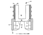
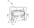
図2は電気コネクタ50の斜視図である。電気コネクタ50は圧力センサカプセル(例えば、図1のカプセル20)から突き出ている圧力センサステム(例えば、図1のステム34)を保護するために使用できる。電気コネクタ50の特定の態様は正面図(図3)、正面断面図(図5の線4−4’に沿って切られた図4)、平面図(図5)、底面図(図6)、または部分斜め断面図(図6の線7−7’に沿って切られた図7)により明瞭に示される。種々の特徴を示すために、図2〜図10を通して同一の参照符号が使用される。
FIG. 2 is a perspective view of the
図2〜図7に示された電気コネクタ50は中央孔54を有する台板52を備え、中央孔54は台板52を貫通している。電気コネクタ50はまた台板52につながる周壁56を含み、図示のように台板52より下に張り出ている。周壁56は、圧力センサステム(例えば、ステム34)が中央孔54を貫通して台板52より上に突き出たときに、圧力センサカプセルの面(例えば、図1のカプセル20の面27)に摺動的に係合するように形成される。台板52の下側部59(図4,図7)および周壁56の内面55(図4)は、好ましくは支持リングの外面(例えば、図1の面27)にフィットする、全体に円筒状の空洞57(図3,図4)を形成する。下側部59は、圧力センサカプセル上に保護装置となる電気コネクタ50を位置決めするための正のストッパとして機能する。
The
電気コネクタ50はさらに台板52につながり圧力センサステム34より上に突き出た保護壁60を備える(図3)。保護壁60は不注意による外部物体による衝撃から圧力センサステム34を保護する。保護壁60は、接合パッド66でセンサ線接合を妨害する危険を生じさせることなく、容易に回路基板に接合するために電気表面取り付け接触子68を配置する。センサ線の接合はパッケージされた圧力センサ組み立てレベルで完成することができ、その後、回路基板の組み立てレベルは困難を伴うことなく、線の接合を完成することができる。接合線は非常に短かいので、動作環境中の衝撃や振動によって損傷することに対して、強固な抵抗を提供する。
The
台板52、周壁56および保護壁60は、好ましくはプラスチック樹脂で形成された射出成型部からなる。圧力センサステム(例えば、図1,3のステム34)はセンサ接触パッド(図1のパッド36)を有し、保護壁60は好ましくはセンサ接触パッドの列に沿ったスロット(slot)62を備える。このスロット62は、接触パッド36(図1)から接合パッド66へ接合線を接合するために、該センサ接触パッド36へアクセスすることを可能にする。
The
電気コネクタ50は、好ましくはスロット62の近傍で保護壁60内に成型(mold)された金属のリードフレーム64を備える。このリードフレーム64は、センサ接触パッド36につながれる接合線に接合するように適合された複数の接合パッド66を含む。リードフレーム64は例示のように複列(dual in-line)パッケージ(DIP)形式に構成され、複数の突き出た面実装(SM)接触子68を含む。リードフレーム64を有する構成により、接合線を、外部の物体との接触から保護される位置へ取り付けることが可能になる。リードフレーム64を有する構成はまた接合線の撓みを防止する。圧力送信機内の取り付けにおいて必要とされた柔軟性のあるあらゆるリードは、本発明ではより頑丈な面実装接触子68に変えられている。リードフレーム64は接触パッド66をセンサ接触パッド36に近付けて置けるようにするので、短くて強固な線接合が可能になる。
The
電気コネクタ50は、好ましくは、台板52につなげられ、かつ突出する面実装接触子68の近くに突き出ている整列ピン70を備える。この整列ピン70は、好ましくは回路基板上で半田パッドに面実装接触子68をよりよく整列させるように回路基板上の整列孔(図示しない)にフィットする。電気コネクタ50は、好ましくは保護壁60内に成型されたRFI保護シールド72を含んでいる。一つの好ましい実施形態では、整列ピン70は金属で形成され、RFI保護シールド72と回路基板上の接地パッドとの間の接続部として機能する。
The
周壁56は、好ましくは圧力センサカプセルの面(例えば、図1の面27)をつかむように形成されたグリップ面61(図6,図7)を含む。このグリップ面は好ましくは例示のようにテーパ形状を有する。このテーパ形状は面27をグリップ面61に押圧させて、電気コネクタ50の取り外しに抵抗する妨害フィットを形成する。グリップ面61はまた面27上での電気コネクタ50の回転に対して抵抗する。
The
保護壁60は好ましくは圧力センサステムの周囲にポッティング空洞74を形成するように型どられる。ポッティング空洞74は、ポッティングコンパウンドで充填されるように型どられており、ステム34と接合線は、より一層の保護のために、該ポッティング空洞74内に入れられることができる。
The
必要ならば、接合パッド64に接続する小型電子回路を取り付けるために、部品実装面76(図2)のような面を使用することができる。
If necessary, a surface such as the component mounting surface 76 (FIG. 2) can be used to attach a small electronic circuit that connects to the
台板52は、好ましくは例示のように保護壁60から外に向かって周囲に拡張され、かつ保護壁60はその中に電気コネクタ50が挿入される取付孔(図示しない)に係合するために用いられる外部面78を有する。
The
電気コネクタ50のような電気コネクタは、リード線が破損したり、センサステムが破損したりするという問題を解決し、電気接合線もしくはセンサステムの不当な破損を伴わずに製造環境内で都合良く操作することができる圧力センサカプセル20を有する組立体を提供する。
An electrical connector, such as
図8〜10は型(図示しない)内においてリードフレーム64を位置決めするのに有用なリードキャリア構造80を例示する。リードフレーム64はリードキャリア構造80の一部であり、これは、成型が完了し、かつリードが最終形状に折り曲げられた後に、リードキャリア構造80の要部から切り離される。図8に例示するように、リードキャリア構造80は型内での整列のための切り欠き(notch)84を含む。リードキャリア構造80は、プラスチック樹脂型への正しい整列を確実にするため、型内の予定位置に各リードを保持する。リードフレーム64内の各リードは、曲げ操作中に、成型された部分内でリードが滑るのを防止するための突き出たタブ86を含む。この突き出たタブ86は好ましくは保護壁60の内側に成型される。図9および図10は、成型の完了後、電気コネクタ50内に固定されたリードキャリア構造80であって、リードフレーム64が折り曲げられる前、およびリードキャリア構造80からリードフレーム64が切り離される前の正面図および平面図をそれぞれ示す。リードキャリア構造80は好ましくは打ち抜かれ、エッチもしくはレーザ加工された面状金属構成部品である。
FIGS. 8-10 illustrate a
本発明は好ましい実施形態により説明されたが、当業者は形状および細部において本発明の範囲から逸脱しないで変形できることを認識できるであろう。また、例示した実施形態では分離されたリードを有するリードフレームを示すが、当業者は、可撓性回路を備えるリードフレームを使用してセンサステム上の接触パッドへ直接接続でき、センサパッドに対して線を接合する必要をなくすことを当業者は理解できるであろう。 Although the present invention has been described in terms of preferred embodiments, those skilled in the art will recognize that changes may be made in form and detail without departing from the scope of the invention. Also, although the illustrated embodiment shows a lead frame having separate leads, those skilled in the art can use a lead frame with a flexible circuit to connect directly to the contact pads on the sensor stem, with respect to the sensor pads. Those skilled in the art will understand that it is not necessary to join the wires together.
20……圧力センサカプセル
22、24……半ブロック
25……支持リング
26……センサ取付孔
27……外面
28……流体流入管
30……圧力センサ
32……ネック
34……圧力センサステム
36……センサ接触パッド
20 ...
Claims (9)
台板と、
該台板を貫通する中央孔と、
前記台板につながり、かつ該台板より下に張り出ていて、圧力センサステムが前記中央孔を貫通して前記台板より上に突き出たときに圧力センサカプセルに対して摺動可能に係合するように形成された周壁と、
前記台板につながって前記圧力センサステムより上に突き出て圧力センサステムを保護する保護壁と、
前記保護壁内に配置され、圧力センサステム上のセンサ接触パッドとの電気接続を提供するリードフレームとを備え、
前記保護壁は、前記圧力センサステムの周りにポッティング空洞を形成し、該ポッティング空洞はポッティングコンパウンドの充填用に形作られ、
前記圧力センサステムがセンサの電気接触パッドを有し、前記保護壁が前記センサの接触パッドの列に沿ったスロットを備えて成る電気コネクタ。 In the electrical connector for connection to the pressure sensor stem protruding from the pressure sensor capsule,
A base plate,
A central hole passing through the base plate;
The pressure sensor stem is connected to the base plate and projects below the base plate so as to be slidable with respect to the pressure sensor capsule when the pressure sensor stem protrudes above the base plate through the central hole. A peripheral wall formed to match,
A protective wall connected to the base plate and protruding above the pressure sensor stem to protect the pressure sensor stem;
A lead frame disposed within the protective wall and providing electrical connection with a sensor contact pad on the pressure sensor stem;
The protective wall forms a potting cavity around the pressure sensor stem, the potting cavity being shaped for filling a potting compound ;
An electrical connector wherein the pressure sensor stem has electrical contact pads for the sensor and the protective wall comprises a slot along the row of contact pads for the sensor .
Applications Claiming Priority (2)
| Application Number | Priority Date | Filing Date | Title |
|---|---|---|---|
| US10/446457 | 2003-05-28 | ||
| US10/446,457 US6722927B1 (en) | 2003-05-28 | 2003-05-28 | Electrical connector for a pressure sensor stem |
Publications (3)
| Publication Number | Publication Date |
|---|---|
| JP2004354384A JP2004354384A (en) | 2004-12-16 |
| JP2004354384A5 JP2004354384A5 (en) | 2007-04-05 |
| JP4726434B2 true JP4726434B2 (en) | 2011-07-20 |
Family
ID=32070011
Family Applications (1)
| Application Number | Title | Priority Date | Filing Date |
|---|---|---|---|
| JP2004157525A Expired - Lifetime JP4726434B2 (en) | 2003-05-28 | 2004-05-27 | Electrical connector for pressure sensor stem |
Country Status (4)
| Country | Link |
|---|---|
| US (1) | US6722927B1 (en) |
| JP (1) | JP4726434B2 (en) |
| CN (1) | CN100337103C (en) |
| DE (1) | DE102004026220B4 (en) |
Cited By (1)
| Publication number | Priority date | Publication date | Assignee | Title |
|---|---|---|---|---|
| JP2017529541A (en) * | 2014-09-30 | 2017-10-05 | ローズマウント インコーポレイテッド | Electrical interconnection for pressure sensors in process variable transmitters |
Families Citing this family (7)
| Publication number | Priority date | Publication date | Assignee | Title |
|---|---|---|---|---|
| CA2643051C (en) * | 2006-02-21 | 2013-01-29 | Rosemount Inc. | Industrial process field device with energy limited battery assembly |
| DE202009001989U1 (en) * | 2009-03-23 | 2009-06-10 | Kumatec Sondermaschinenbau & Kunststoffverarbeitung Gmbh | Plug housing made of plastic for a connector |
| JP5136861B2 (en) * | 2009-03-27 | 2013-02-06 | 住友電装株式会社 | Shield connector |
| US9442031B2 (en) | 2013-06-28 | 2016-09-13 | Rosemount Inc. | High integrity process fluid pressure probe |
| US9459170B2 (en) | 2013-09-26 | 2016-10-04 | Rosemount Inc. | Process fluid pressure sensing assembly for pressure transmitters subjected to high working pressure |
| US10209154B2 (en) | 2015-03-30 | 2019-02-19 | Rosemount Inc. | In-line process fluid pressure transmitter for high pressure applications |
| US10756471B1 (en) * | 2019-06-04 | 2020-08-25 | Te Connectivity Corporation | Shield grounding electrical connectors |
Citations (8)
| Publication number | Priority date | Publication date | Assignee | Title |
|---|---|---|---|---|
| JPH05145085A (en) * | 1991-11-25 | 1993-06-11 | Nippondenso Co Ltd | Semiconductor pressure sensor |
| JPH10275648A (en) * | 1997-03-29 | 1998-10-13 | Omron Corp | Connector |
| JPH1123400A (en) * | 1997-05-09 | 1999-01-29 | Fuji Koki Corp | Pressure sensor |
| JPH11250995A (en) * | 1997-12-15 | 1999-09-17 | Molex Inc | Shield electric connector assembly provided with grounding mechanism |
| JP2000055762A (en) * | 1998-08-04 | 2000-02-25 | Denso Corp | Pressure detecting device |
| JP2001108544A (en) * | 1999-10-06 | 2001-04-20 | Denso Corp | Semiconductor sensor |
| JP2001291543A (en) * | 2000-04-06 | 2001-10-19 | Fujikura Ltd | Connector for surface mounting and its mounting structure |
| US20020100333A1 (en) * | 2000-01-06 | 2002-08-01 | Gravel James L. | Sensor with fluid isolation barrier |
Family Cites Families (12)
| Publication number | Priority date | Publication date | Assignee | Title |
|---|---|---|---|---|
| US4785532A (en) * | 1985-10-22 | 1988-11-22 | Amp Incorporated | Method of making electrical connector assembly for antiskid braking system |
| JPH0843224A (en) * | 1994-08-01 | 1996-02-16 | Matsushita Electric Ind Co Ltd | Pressure detecting device |
| US5637802A (en) | 1995-02-28 | 1997-06-10 | Rosemount Inc. | Capacitive pressure sensor for a pressure transmitted where electric field emanates substantially from back sides of plates |
| US5711552A (en) * | 1995-04-05 | 1998-01-27 | General Electric Company | Coupling |
| US5853020A (en) * | 1995-06-23 | 1998-12-29 | Widner; Ronald D. | Miniature combination valve and pressure transducer and system |
| US6148681A (en) * | 1997-01-06 | 2000-11-21 | Rosemount Inc. | Level probe with modular connection |
| US6131467A (en) * | 1997-05-09 | 2000-10-17 | Fujikoki Corporation | Pressure sensor including a joint for connecting a housing and connector case together |
| US6506069B2 (en) * | 2001-01-25 | 2003-01-14 | Kelsey-Hayes Company | Floating electrical connector for a pressure sensor |
| JP4003363B2 (en) * | 1999-12-24 | 2007-11-07 | 株式会社デンソー | Combustion pressure sensor structure |
| US6508129B1 (en) | 2000-01-06 | 2003-01-21 | Rosemount Inc. | Pressure sensor capsule with improved isolation |
| US6584851B2 (en) * | 2000-11-30 | 2003-07-01 | Nagano Keiki Co., Ltd. | Fluid pressure sensor having a pressure port |
| DE20111343U1 (en) * | 2001-07-07 | 2001-10-18 | Abb Patent Gmbh, 68309 Mannheim | Measuring unit for differential pressure measurement |
-
2003
- 2003-05-28 US US10/446,457 patent/US6722927B1/en not_active Expired - Lifetime
-
2004
- 2004-05-27 JP JP2004157525A patent/JP4726434B2/en not_active Expired - Lifetime
- 2004-05-28 CN CNB2004100639261A patent/CN100337103C/en not_active Expired - Fee Related
- 2004-05-28 DE DE102004026220.9A patent/DE102004026220B4/en not_active Expired - Fee Related
Patent Citations (8)
| Publication number | Priority date | Publication date | Assignee | Title |
|---|---|---|---|---|
| JPH05145085A (en) * | 1991-11-25 | 1993-06-11 | Nippondenso Co Ltd | Semiconductor pressure sensor |
| JPH10275648A (en) * | 1997-03-29 | 1998-10-13 | Omron Corp | Connector |
| JPH1123400A (en) * | 1997-05-09 | 1999-01-29 | Fuji Koki Corp | Pressure sensor |
| JPH11250995A (en) * | 1997-12-15 | 1999-09-17 | Molex Inc | Shield electric connector assembly provided with grounding mechanism |
| JP2000055762A (en) * | 1998-08-04 | 2000-02-25 | Denso Corp | Pressure detecting device |
| JP2001108544A (en) * | 1999-10-06 | 2001-04-20 | Denso Corp | Semiconductor sensor |
| US20020100333A1 (en) * | 2000-01-06 | 2002-08-01 | Gravel James L. | Sensor with fluid isolation barrier |
| JP2001291543A (en) * | 2000-04-06 | 2001-10-19 | Fujikura Ltd | Connector for surface mounting and its mounting structure |
Cited By (1)
| Publication number | Priority date | Publication date | Assignee | Title |
|---|---|---|---|---|
| JP2017529541A (en) * | 2014-09-30 | 2017-10-05 | ローズマウント インコーポレイテッド | Electrical interconnection for pressure sensors in process variable transmitters |
Also Published As
| Publication number | Publication date |
|---|---|
| JP2004354384A (en) | 2004-12-16 |
| US6722927B1 (en) | 2004-04-20 |
| DE102004026220B4 (en) | 2015-09-24 |
| CN100337103C (en) | 2007-09-12 |
| DE102004026220A1 (en) | 2005-02-10 |
| CN1573308A (en) | 2005-02-02 |
Similar Documents
| Publication | Publication Date | Title |
|---|---|---|
| US6432737B1 (en) | Method for forming a flip chip pressure sensor die package | |
| US8035208B2 (en) | Integrated circuit package | |
| US6441503B1 (en) | Bond wire pressure sensor die package | |
| US8643127B2 (en) | Sensor device packaging | |
| US20080277747A1 (en) | MEMS device support structure for sensor packaging | |
| EP3124935B1 (en) | Sensor package | |
| US6420201B1 (en) | Method for forming a bond wire pressure sensor die package | |
| JP4726434B2 (en) | Electrical connector for pressure sensor stem | |
| JP2007501937A (en) | Sensor module | |
| EP3575765B1 (en) | Overmolded lead frame assembly for pressure sensing applications | |
| JP6462187B2 (en) | Manufacture of catheter sensors | |
| KR100834337B1 (en) | Pressure sensor device and manufacturing method thereof | |
| JP2009192424A (en) | Temperature sensor and temperature sensor integrated pressure sensor | |
| KR102242428B1 (en) | Strain gauge pressure sensor | |
| JP5175538B2 (en) | Waterproof mounting structure of the sensor | |
| US7084473B2 (en) | Semiconductor package with an optical sensor which may be fit inside an object | |
| US20020067554A1 (en) | Optical module | |
| JP2004354384A5 (en) | ||
| CN105181216B (en) | Strain gauge type pressure sensor | |
| JP6170879B2 (en) | Strain gauge pressure sensor | |
| KR20110076539A (en) | Pressure sensor and manufacture method thereof | |
| KR101628267B1 (en) | Pressure sensor | |
| JP2006024959A (en) | Semiconductor apparatus | |
| EP2950070B1 (en) | Strain gauge pressure sensor | |
| JP2007192790A (en) | Semiconductor pressure sensor |
Legal Events
| Date | Code | Title | Description |
|---|---|---|---|
| A521 | Request for written amendment filed |
Free format text: JAPANESE INTERMEDIATE CODE: A523 Effective date: 20070214 |
|
| A621 | Written request for application examination |
Free format text: JAPANESE INTERMEDIATE CODE: A621 Effective date: 20070214 |
|
| A977 | Report on retrieval |
Free format text: JAPANESE INTERMEDIATE CODE: A971007 Effective date: 20100115 |
|
| A131 | Notification of reasons for refusal |
Free format text: JAPANESE INTERMEDIATE CODE: A131 Effective date: 20100324 |
|
| A521 | Request for written amendment filed |
Free format text: JAPANESE INTERMEDIATE CODE: A523 Effective date: 20100609 |
|
| A131 | Notification of reasons for refusal |
Free format text: JAPANESE INTERMEDIATE CODE: A131 Effective date: 20101201 |
|
| A521 | Request for written amendment filed |
Free format text: JAPANESE INTERMEDIATE CODE: A523 Effective date: 20110222 |
|
| A01 | Written decision to grant a patent or to grant a registration (utility model) |
Free format text: JAPANESE INTERMEDIATE CODE: A01 Effective date: 20110316 |
|
| A61 | First payment of annual fees (during grant procedure) |
Free format text: JAPANESE INTERMEDIATE CODE: A61 Effective date: 20110412 |
|
| R150 | Certificate of patent or registration of utility model |
Free format text: JAPANESE INTERMEDIATE CODE: R150 |
|
| FPAY | Renewal fee payment (event date is renewal date of database) |
Free format text: PAYMENT UNTIL: 20140422 Year of fee payment: 3 |
|
| R250 | Receipt of annual fees |
Free format text: JAPANESE INTERMEDIATE CODE: R250 |
|
| R250 | Receipt of annual fees |
Free format text: JAPANESE INTERMEDIATE CODE: R250 |
|
| R250 | Receipt of annual fees |
Free format text: JAPANESE INTERMEDIATE CODE: R250 |
|
| R250 | Receipt of annual fees |
Free format text: JAPANESE INTERMEDIATE CODE: R250 |
|
| R250 | Receipt of annual fees |
Free format text: JAPANESE INTERMEDIATE CODE: R250 |
|
| R250 | Receipt of annual fees |
Free format text: JAPANESE INTERMEDIATE CODE: R250 |