JP4719278B2 - Adapter for applying negative pressure wound therapy to tissue sites - Google Patents
Adapter for applying negative pressure wound therapy to tissue sites Download PDFInfo
- Publication number
- JP4719278B2 JP4719278B2 JP2008553402A JP2008553402A JP4719278B2 JP 4719278 B2 JP4719278 B2 JP 4719278B2 JP 2008553402 A JP2008553402 A JP 2008553402A JP 2008553402 A JP2008553402 A JP 2008553402A JP 4719278 B2 JP4719278 B2 JP 4719278B2
- Authority
- JP
- Japan
- Prior art keywords
- adapter
- negative pressure
- auxiliary
- conduit
- base
- Prior art date
- Legal status (The legal status is an assumption and is not a legal conclusion. Google has not performed a legal analysis and makes no representation as to the accuracy of the status listed.)
- Active
Links
- 238000009581 negative-pressure wound therapy Methods 0.000 title claims description 7
- 239000007788 liquid Substances 0.000 claims description 40
- 239000012530 fluid Substances 0.000 claims description 39
- 239000012855 volatile organic compound Substances 0.000 claims description 14
- 238000004891 communication Methods 0.000 claims description 12
- 238000001514 detection method Methods 0.000 claims description 10
- 206010052428 Wound Diseases 0.000 description 68
- 208000027418 Wounds and injury Diseases 0.000 description 65
- 210000001519 tissue Anatomy 0.000 description 16
- 238000000034 method Methods 0.000 description 14
- 238000005259 measurement Methods 0.000 description 10
- 239000000463 material Substances 0.000 description 9
- 244000005700 microbiome Species 0.000 description 8
- 230000017531 blood circulation Effects 0.000 description 5
- 238000009530 blood pressure measurement Methods 0.000 description 5
- 230000004044 response Effects 0.000 description 5
- 230000006872 improvement Effects 0.000 description 4
- 238000012544 monitoring process Methods 0.000 description 4
- 239000000853 adhesive Substances 0.000 description 3
- 230000001070 adhesive effect Effects 0.000 description 3
- 230000009286 beneficial effect Effects 0.000 description 3
- 210000000981 epithelium Anatomy 0.000 description 3
- 239000006260 foam Substances 0.000 description 3
- 230000004054 inflammatory process Effects 0.000 description 3
- 238000003780 insertion Methods 0.000 description 3
- 230000037431 insertion Effects 0.000 description 3
- 206010033675 panniculitis Diseases 0.000 description 3
- 230000002093 peripheral effect Effects 0.000 description 3
- 210000004304 subcutaneous tissue Anatomy 0.000 description 3
- 239000000126 substance Substances 0.000 description 3
- 241000894006 Bacteria Species 0.000 description 2
- 230000035876 healing Effects 0.000 description 2
- 230000036541 health Effects 0.000 description 2
- 238000013508 migration Methods 0.000 description 2
- 230000005012 migration Effects 0.000 description 2
- 239000004033 plastic Substances 0.000 description 2
- 230000008569 process Effects 0.000 description 2
- 238000002560 therapeutic procedure Methods 0.000 description 2
- 208000035143 Bacterial infection Diseases 0.000 description 1
- 208000032912 Local swelling Diseases 0.000 description 1
- 206010030113 Oedema Diseases 0.000 description 1
- 206010031256 Osteomyelitis chronic Diseases 0.000 description 1
- 208000004210 Pressure Ulcer Diseases 0.000 description 1
- 208000025865 Ulcer Diseases 0.000 description 1
- 238000013459 approach Methods 0.000 description 1
- QVGXLLKOCUKJST-UHFFFAOYSA-N atomic oxygen Chemical compound [O] QVGXLLKOCUKJST-UHFFFAOYSA-N 0.000 description 1
- 208000022362 bacterial infectious disease Diseases 0.000 description 1
- 230000033228 biological regulation Effects 0.000 description 1
- 230000015572 biosynthetic process Effects 0.000 description 1
- 210000004204 blood vessel Anatomy 0.000 description 1
- 230000008859 change Effects 0.000 description 1
- 230000008602 contraction Effects 0.000 description 1
- 230000003111 delayed effect Effects 0.000 description 1
- 238000013461 design Methods 0.000 description 1
- 238000011161 development Methods 0.000 description 1
- 230000018109 developmental process Effects 0.000 description 1
- 238000010586 diagram Methods 0.000 description 1
- 230000000694 effects Effects 0.000 description 1
- 239000007789 gas Substances 0.000 description 1
- 230000002439 hemostatic effect Effects 0.000 description 1
- 230000006698 induction Effects 0.000 description 1
- 208000015181 infectious disease Diseases 0.000 description 1
- 239000012633 leachable Substances 0.000 description 1
- 239000011344 liquid material Substances 0.000 description 1
- 238000007726 management method Methods 0.000 description 1
- 230000000813 microbial effect Effects 0.000 description 1
- 238000012986 modification Methods 0.000 description 1
- 230000004048 modification Effects 0.000 description 1
- 238000012806 monitoring device Methods 0.000 description 1
- 238000000465 moulding Methods 0.000 description 1
- 235000015097 nutrients Nutrition 0.000 description 1
- 238000007557 optical granulometry Methods 0.000 description 1
- 239000001301 oxygen Substances 0.000 description 1
- 229910052760 oxygen Inorganic materials 0.000 description 1
- 229920000642 polymer Polymers 0.000 description 1
- 230000001681 protective effect Effects 0.000 description 1
- 238000000746 purification Methods 0.000 description 1
- 238000011084 recovery Methods 0.000 description 1
- 230000008929 regeneration Effects 0.000 description 1
- 238000011069 regeneration method Methods 0.000 description 1
- 230000001105 regulatory effect Effects 0.000 description 1
- 230000000717 retained effect Effects 0.000 description 1
- 230000037380 skin damage Effects 0.000 description 1
- 239000011343 solid material Substances 0.000 description 1
- 229920001169 thermoplastic Polymers 0.000 description 1
- 239000004416 thermosoftening plastic Substances 0.000 description 1
- 230000000451 tissue damage Effects 0.000 description 1
- 231100000827 tissue damage Toxicity 0.000 description 1
- 239000012780 transparent material Substances 0.000 description 1
- 231100000397 ulcer Toxicity 0.000 description 1
- 230000002792 vascular Effects 0.000 description 1
Images


Classifications
-
- A—HUMAN NECESSITIES
- A61—MEDICAL OR VETERINARY SCIENCE; HYGIENE
- A61M—DEVICES FOR INTRODUCING MEDIA INTO, OR ONTO, THE BODY; DEVICES FOR TRANSDUCING BODY MEDIA OR FOR TAKING MEDIA FROM THE BODY; DEVICES FOR PRODUCING OR ENDING SLEEP OR STUPOR
- A61M1/00—Suction or pumping devices for medical purposes; Devices for carrying-off, for treatment of, or for carrying-over, body-liquids; Drainage systems
-
- A61F13/05—
-
- A—HUMAN NECESSITIES
- A61—MEDICAL OR VETERINARY SCIENCE; HYGIENE
- A61F—FILTERS IMPLANTABLE INTO BLOOD VESSELS; PROSTHESES; DEVICES PROVIDING PATENCY TO, OR PREVENTING COLLAPSING OF, TUBULAR STRUCTURES OF THE BODY, e.g. STENTS; ORTHOPAEDIC, NURSING OR CONTRACEPTIVE DEVICES; FOMENTATION; TREATMENT OR PROTECTION OF EYES OR EARS; BANDAGES, DRESSINGS OR ABSORBENT PADS; FIRST-AID KITS
- A61F13/00—Bandages or dressings; Absorbent pads
-
- A—HUMAN NECESSITIES
- A61—MEDICAL OR VETERINARY SCIENCE; HYGIENE
- A61M—DEVICES FOR INTRODUCING MEDIA INTO, OR ONTO, THE BODY; DEVICES FOR TRANSDUCING BODY MEDIA OR FOR TAKING MEDIA FROM THE BODY; DEVICES FOR PRODUCING OR ENDING SLEEP OR STUPOR
- A61M1/00—Suction or pumping devices for medical purposes; Devices for carrying-off, for treatment of, or for carrying-over, body-liquids; Drainage systems
- A61M1/71—Suction drainage systems
- A61M1/73—Suction drainage systems comprising sensors or indicators for physical values
-
- A—HUMAN NECESSITIES
- A61—MEDICAL OR VETERINARY SCIENCE; HYGIENE
- A61M—DEVICES FOR INTRODUCING MEDIA INTO, OR ONTO, THE BODY; DEVICES FOR TRANSDUCING BODY MEDIA OR FOR TAKING MEDIA FROM THE BODY; DEVICES FOR PRODUCING OR ENDING SLEEP OR STUPOR
- A61M1/00—Suction or pumping devices for medical purposes; Devices for carrying-off, for treatment of, or for carrying-over, body-liquids; Drainage systems
- A61M1/71—Suction drainage systems
- A61M1/74—Suction control
- A61M1/743—Suction control by changing the cross-section of the line, e.g. flow regulating valves
-
- A—HUMAN NECESSITIES
- A61—MEDICAL OR VETERINARY SCIENCE; HYGIENE
- A61M—DEVICES FOR INTRODUCING MEDIA INTO, OR ONTO, THE BODY; DEVICES FOR TRANSDUCING BODY MEDIA OR FOR TAKING MEDIA FROM THE BODY; DEVICES FOR PRODUCING OR ENDING SLEEP OR STUPOR
- A61M1/00—Suction or pumping devices for medical purposes; Devices for carrying-off, for treatment of, or for carrying-over, body-liquids; Drainage systems
- A61M1/90—Negative pressure wound therapy devices, i.e. devices for applying suction to a wound to promote healing, e.g. including a vacuum dressing
- A61M1/91—Suction aspects of the dressing
- A61M1/912—Connectors between dressing and drainage tube
-
- A—HUMAN NECESSITIES
- A61—MEDICAL OR VETERINARY SCIENCE; HYGIENE
- A61M—DEVICES FOR INTRODUCING MEDIA INTO, OR ONTO, THE BODY; DEVICES FOR TRANSDUCING BODY MEDIA OR FOR TAKING MEDIA FROM THE BODY; DEVICES FOR PRODUCING OR ENDING SLEEP OR STUPOR
- A61M1/00—Suction or pumping devices for medical purposes; Devices for carrying-off, for treatment of, or for carrying-over, body-liquids; Drainage systems
- A61M1/90—Negative pressure wound therapy devices, i.e. devices for applying suction to a wound to promote healing, e.g. including a vacuum dressing
- A61M1/91—Suction aspects of the dressing
- A61M1/915—Constructional details of the pressure distribution manifold
-
- A—HUMAN NECESSITIES
- A61—MEDICAL OR VETERINARY SCIENCE; HYGIENE
- A61M—DEVICES FOR INTRODUCING MEDIA INTO, OR ONTO, THE BODY; DEVICES FOR TRANSDUCING BODY MEDIA OR FOR TAKING MEDIA FROM THE BODY; DEVICES FOR PRODUCING OR ENDING SLEEP OR STUPOR
- A61M1/00—Suction or pumping devices for medical purposes; Devices for carrying-off, for treatment of, or for carrying-over, body-liquids; Drainage systems
- A61M1/90—Negative pressure wound therapy devices, i.e. devices for applying suction to a wound to promote healing, e.g. including a vacuum dressing
- A61M1/95—Negative pressure wound therapy devices, i.e. devices for applying suction to a wound to promote healing, e.g. including a vacuum dressing with sensors for exudate composition
-
- A—HUMAN NECESSITIES
- A61—MEDICAL OR VETERINARY SCIENCE; HYGIENE
- A61M—DEVICES FOR INTRODUCING MEDIA INTO, OR ONTO, THE BODY; DEVICES FOR TRANSDUCING BODY MEDIA OR FOR TAKING MEDIA FROM THE BODY; DEVICES FOR PRODUCING OR ENDING SLEEP OR STUPOR
- A61M1/00—Suction or pumping devices for medical purposes; Devices for carrying-off, for treatment of, or for carrying-over, body-liquids; Drainage systems
- A61M1/90—Negative pressure wound therapy devices, i.e. devices for applying suction to a wound to promote healing, e.g. including a vacuum dressing
- A61M1/96—Suction control thereof
- A61M1/966—Suction control thereof having a pressure sensor on or near the dressing
-
- A—HUMAN NECESSITIES
- A61—MEDICAL OR VETERINARY SCIENCE; HYGIENE
- A61M—DEVICES FOR INTRODUCING MEDIA INTO, OR ONTO, THE BODY; DEVICES FOR TRANSDUCING BODY MEDIA OR FOR TAKING MEDIA FROM THE BODY; DEVICES FOR PRODUCING OR ENDING SLEEP OR STUPOR
- A61M31/00—Devices for introducing or retaining media, e.g. remedies, in cavities of the body
-
- A—HUMAN NECESSITIES
- A61—MEDICAL OR VETERINARY SCIENCE; HYGIENE
- A61M—DEVICES FOR INTRODUCING MEDIA INTO, OR ONTO, THE BODY; DEVICES FOR TRANSDUCING BODY MEDIA OR FOR TAKING MEDIA FROM THE BODY; DEVICES FOR PRODUCING OR ENDING SLEEP OR STUPOR
- A61M1/00—Suction or pumping devices for medical purposes; Devices for carrying-off, for treatment of, or for carrying-over, body-liquids; Drainage systems
- A61M1/71—Suction drainage systems
- A61M1/74—Suction control
- A61M1/75—Intermittent or pulsating suction
-
- A—HUMAN NECESSITIES
- A61—MEDICAL OR VETERINARY SCIENCE; HYGIENE
- A61M—DEVICES FOR INTRODUCING MEDIA INTO, OR ONTO, THE BODY; DEVICES FOR TRANSDUCING BODY MEDIA OR FOR TAKING MEDIA FROM THE BODY; DEVICES FOR PRODUCING OR ENDING SLEEP OR STUPOR
- A61M1/00—Suction or pumping devices for medical purposes; Devices for carrying-off, for treatment of, or for carrying-over, body-liquids; Drainage systems
- A61M1/90—Negative pressure wound therapy devices, i.e. devices for applying suction to a wound to promote healing, e.g. including a vacuum dressing
- A61M1/96—Suction control thereof
- A61M1/964—Suction control thereof having venting means on or near the dressing
-
- A—HUMAN NECESSITIES
- A61—MEDICAL OR VETERINARY SCIENCE; HYGIENE
- A61M—DEVICES FOR INTRODUCING MEDIA INTO, OR ONTO, THE BODY; DEVICES FOR TRANSDUCING BODY MEDIA OR FOR TAKING MEDIA FROM THE BODY; DEVICES FOR PRODUCING OR ENDING SLEEP OR STUPOR
- A61M2205/00—General characteristics of the apparatus
- A61M2205/33—Controlling, regulating or measuring
- A61M2205/3331—Pressure; Flow
- A61M2205/3344—Measuring or controlling pressure at the body treatment site
-
- A—HUMAN NECESSITIES
- A61—MEDICAL OR VETERINARY SCIENCE; HYGIENE
- A61M—DEVICES FOR INTRODUCING MEDIA INTO, OR ONTO, THE BODY; DEVICES FOR TRANSDUCING BODY MEDIA OR FOR TAKING MEDIA FROM THE BODY; DEVICES FOR PRODUCING OR ENDING SLEEP OR STUPOR
- A61M2205/00—General characteristics of the apparatus
- A61M2205/58—Means for facilitating use, e.g. by people with impaired vision
- A61M2205/583—Means for facilitating use, e.g. by people with impaired vision by visual feedback
- A61M2205/584—Means for facilitating use, e.g. by people with impaired vision by visual feedback having a color code
Landscapes
- Health & Medical Sciences (AREA)
- Heart & Thoracic Surgery (AREA)
- General Health & Medical Sciences (AREA)
- Engineering & Computer Science (AREA)
- Biomedical Technology (AREA)
- Life Sciences & Earth Sciences (AREA)
- Animal Behavior & Ethology (AREA)
- Public Health (AREA)
- Veterinary Medicine (AREA)
- Vascular Medicine (AREA)
- Anesthesiology (AREA)
- Hematology (AREA)
- External Artificial Organs (AREA)
- Media Introduction/Drainage Providing Device (AREA)
- Surgery (AREA)
Description
本発明は、一般に組織、特に開放創傷に負圧治療を提供するシステム及び方法に関する。具体的には、本発明は、負圧創傷治療(RPWT)に関連して使用する組織ドレッシングと負圧源の装置の間の連結を改良するシステム及び方法に関する。 The present invention relates generally to systems and methods for providing negative pressure therapy to tissue, particularly open wounds. Specifically, the present invention relates to a system and method for improving the connection between a tissue dressing and a negative pressure source device for use in connection with negative pressure wound therapy (RPWT).
長年にわたり、創傷の閉鎖と回復過程を促進するために様々な治療方法が研究されてきた。創傷閉鎖は、一般的に、創傷に近接する上皮及び皮下組織の内部移動を伴う。この移動は通常、炎症過程によって助長され、これによって血流が増えて様々な機能的な細胞型が活性化される。炎症過程の結果、損傷又は破壊された血管を通じた血流は毛細管レベルの閉塞によって止められて、その後に浄化及び再生作用が開始する。残念なことに、この過程は創傷が大きいか感染している場合は阻害されてしまう。このような創傷において、血行停止領域(すなわち、組織の局部的な腫大が組織の血流を抑制する領域)は、創傷の表面近くに形成される。 Over the years, various therapies have been studied to promote the wound closure and healing process. Wound closure generally involves the internal movement of epithelium and subcutaneous tissue adjacent to the wound. This migration is usually facilitated by an inflammatory process, which increases blood flow and activates various functional cell types. As a result of the inflammatory process, blood flow through damaged or destroyed blood vessels is stopped by capillary level occlusion, after which purification and regeneration begins. Unfortunately, this process is hindered if the wound is large or infected. In such a wound, a hemostatic region (ie, a region where local swelling of the tissue inhibits tissue blood flow) is formed near the surface of the wound.
十分な血流がないことによって、傷を囲む上皮及び皮下組織が受容する酸素及び栄養物が少なくなるだけではなく、細菌感染症に対する十分な抵抗力が低くなり、自然に傷を治癒できなくなる。さらに、一部の傷は、ステープルや縫合によって閉鎖できない程に硬化して炎症を生じているものもある。ステープルや縫合によって治療することが難しい創傷には、例えば、大きくて深い開放性の創傷;褥瘡性潰瘍;慢性骨髄炎による潰瘍;十分な厚みの火傷である部分的に厚みのある火傷などがある。 The lack of adequate blood flow not only reduces oxygen and nutrients received by the epithelium and subcutaneous tissue surrounding the wound, but also reduces its resistance to bacterial infections, making it impossible to heal wounds naturally. Furthermore, some wounds are hardened and inflamed so that they cannot be closed by staples or sutures. Wounds that are difficult to treat with staples or sutures include, for example, large and deep open wounds; decubitus ulcers; ulcers due to chronic osteomyelitis; partially thick burns that are full thickness burns .
機械的な創傷閉鎖の器具は欠点を有しており、このことから、連続的および/または断続的な負圧をかけて創傷を排出する方法及び装置が開発されてきた。創傷の十分な範囲にこのような負圧をかけると上皮及び皮下組織の創傷への移動を促進することが分かっている。実際に創傷に負圧をかけると、一般的に、過剰な流体を除去すると同時に傷の機械的な収縮を伴う。この方法では、RPWTは、身体本来の炎症過程を増進させつつ、例えば適正な静脈還流に必要な血管構造が無い場合に血流が増えて生じる浮腫の形成など既知の本質的な副作用の多くを緩和する。 Mechanical wound closure devices have drawbacks, which have led to the development of methods and devices for expelling wounds under continuous and / or intermittent negative pressure. It has been found that applying such negative pressure to a sufficient area of the wound promotes the migration of epithelial and subcutaneous tissue to the wound. In fact, the application of negative pressure to the wound generally involves the mechanical contraction of the wound while removing excess fluid. In this way, RPWT enhances the body's natural inflammatory process, while avoiding many of the known essential side effects, such as the formation of edema resulting from increased blood flow when there is no vascular structure necessary for proper venous return ease.
開放創傷の回復を誘引する真空又は負圧は、近年、テキサス州のサンアントニオにあるKinetic Concepts, Inc.によって、商業上販売されているRPWTシステム製品ラインを通じて普及してきた。回復過程を誘引する負圧は、共に譲渡された1990年11月13日に発行されたZamierowskiによる米国特許第4,969,880号及び1992年3月31日に発行された米国特許第5,100,396号;1993年11月16日に発行された米国特許第5,261,893号;1996年6月18日にに発行された米国特許第5,527,293号を含む関連特許に開示されており、それぞれの開示をここに参照によって組み込んでいる。また、RPWT過程のさらなる改良及び変更は、2000年6月6日に発行されたZamierowskiによる米国特許第6,071,267号及び1997年6月10日、1997年7月8日にそれぞれ発行されたArgenta他による米国特許第5,636,643号、及び第5,645,081号に開示されており、それぞれの開示を十分な説明とともにここに参照によって組み込む。また、1998年5月13日に発行されたHunt他による米国特許第6,142,982号にさらなる改良が開示されている。 Vacuums or negative pressures that induce healing of open wounds have recently been developed by Kinetic Concepts, Inc., San Antonio, Texas. Has been popularized through the commercially sold RPWT system product line. The negative pressure that induces the recovery process is described in U.S. Pat. No. 4,969,880 issued to Zamierowski, issued Nov. 13, 1990 and U.S. Pat. No. 5, issued March 31, 1992, both assigned. 100,396; U.S. Pat. No. 5,261,893 issued Nov. 16, 1993; U.S. Pat. No. 5,527,293 issued Jun. 1996 Each of which is hereby incorporated by reference. Further improvements and changes to the RPWT process were also issued on June 6, 2000 by Zamierowski, US Pat. No. 6,071,267 and June 10, 1997, July 8, 1997, respectively. U.S. Pat. Nos. 5,636,643 and 5,645,081 by Argenta et al., The disclosures of each of which are hereby incorporated by reference together with a full description. Further improvements are disclosed in US Pat. No. 6,142,982 issued on May 13, 1998 to Hunt et al.
RPWTシステムの重要な構成部品の一つは、負圧源(一般的に、真空ポンプ)をパッド又は創傷ドレッシング内に封入された構成部品(一般的に、粒状発泡体層)に連結する器具又は構造である。この負圧ポート構造は、創傷ドレッシングに接着してドレッシングの発泡体層と連通していなければならない。患者に快適さと安全性の双方を提供するために、このポートは取付パッドの性質上、高さが低いことが好ましい。これまで、負圧源を組織部位へ効果的に連結する好適なアダプタ構成(一般的に、チューブを介する)を提供するために様々な努力が成されてきた。 One important component of the RPWT system is an instrument that connects a negative pressure source (typically a vacuum pump) to a component (typically a granular foam layer) enclosed in a pad or wound dressing. It is a structure. This negative pressure port structure must adhere to the wound dressing and communicate with the foam layer of the dressing. In order to provide both comfort and safety for the patient, the port is preferably low in height due to the nature of the mounting pad. In the past, various efforts have been made to provide suitable adapter configurations (generally via tubes) that effectively couple a negative pressure source to a tissue site.
連続的および/または断続的に負圧を創傷にかけることに応じて、RPWTシステムを使用して組織部位の圧力を調整して観察する。従って、組織部位に加える負圧レベルを観察し変化に応答するシステムを提供することが重要である。創傷にかける負圧サイクルを含むRPWTを様々に管理することが一定の環境下において有益であることが分かっている。他の状況では、負圧の付加を精密にではなく一定に調整することが有益である。どんな場合においても組織部位にかける負圧レベルを正確に観察することが有益である。 The RPWT system is used to adjust and observe the pressure at the tissue site in response to applying negative pressure to the wound continuously and / or intermittently. Therefore, it is important to provide a system that observes negative pressure levels applied to a tissue site and responds to changes. Various management of RPWT, including negative pressure cycles applied to wounds, has been found to be beneficial in certain circumstances. In other situations, it is beneficial to adjust the negative pressure application to be constant rather than precise. In any case, it is beneficial to accurately observe the level of negative pressure applied to the tissue site.
一般的に、負圧源が提供する負圧のレベルを負圧源であるいは負圧源を創傷ドレッシングに連結する管路中のいずれかにおいて単に測定するだけでは、組織部位の圧力レベルを特徴付けることはできない。RPWTシステムに接続されたチューブの主管腔内の流動は、装置に使用する圧力レベル測定器が組織部位自体の圧力のレベル又は安定性の正確な指示計となることを妨げる。従って、創傷の圧力レベルを直接監視するための他の方法が必要である。 Generally, simply measuring the level of negative pressure provided by a negative pressure source, either at the negative pressure source or in the conduit connecting the negative pressure source to the wound dressing, characterizes the pressure level at the tissue site I can't. The flow in the main lumen of the tube connected to the RPWT system prevents the pressure level meter used in the device from being an accurate indicator of the pressure level or stability of the tissue site itself. Accordingly, there is a need for other methods for directly monitoring wound pressure levels.
これまで、監視装置に連結された創傷部位に対し分離した圧力検知又は測定用の導管を提供するために、いくつかの取り組みが行われてきた。これらの取り組みは、一般に、RPWTチューブ内に個別の管腔を提供するか、チューブの個々の部分を全体的に使用してきた。しかしながら、このようなシステムを形成する条件は、補助的な測定用の管腔又は測定用のチューブが開いており、創傷ドレッシングのポートまで詰まりがないことである。RPWTシステムの主要な流体管腔で行うように測定用の管腔では強制的に中の流体を流さないということにもかかわらず、この機能を制限するか完全に止めてしまう流体及び他の物質をまだ収集するため、これは必ずしも効果的な条件ではない。この測定用管腔の断面を小さくすることはポートの大きさを小さくしてしまうので、流体や他の物質がポートに入る機会を減らすことはできるが、その小さな断面によって微細な詰まりは著しくなる。 In the past, several efforts have been made to provide a separate pressure sensing or measuring conduit for a wound site coupled to a monitoring device. These approaches have generally provided separate lumens within the RPWT tube or have used individual portions of the tube as a whole. However, a condition for forming such a system is that the auxiliary measuring lumen or measuring tube is open and does not clog the wound dressing port. Fluids and other substances that restrict or completely stop this function despite the fact that the measurement lumen is not forced to flow in the measurement lumen as it does in the main fluid lumen of the RPWT system This is not necessarily an effective condition because it still collects. Reducing the cross-section of this measuring lumen reduces the size of the port, which can reduce the chance of fluids and other materials entering the port, but the small cross-section can cause significant clogging. .
本発明の例示的な実施例では、負圧創傷治療(RPWT)システムの創傷ドレッシングと負圧源の間の連結部品の構造及び使用を改良している。さらに具体的には、ある例示的な実施例は:
(A)操作の信頼性を改良し、測定用の管腔内へ意図していない流体が入ることを防止するあるいは減らす高さの低い負圧アダプタと;
(B)後述する動的な圧力機能を支持するための大きい内側の管腔と、小さい外側の管腔とを具える長円形のチューブ構造を具える改良された負圧供給チューブと;
(C)RPWTシステムに圧力の調整器が設けられている状態で特定の課題を克服することができる創傷圧力を測定する改良された動的方法と;
(D)患者への取付具の快適さを実現するように回転機能を具える改良された負圧アダプタ構造と;
(E)前記負圧アダプタ及びここを通って移送される流体内の細菌の存在の指標を提供する構造と;
を提供する。
Exemplary embodiments of the present invention improve the structure and use of the connecting component between the wound dressing and the negative pressure source of the negative pressure wound therapy (RPWT) system. More specifically, one illustrative example is:
(A) a low-pressure adapter with a low height that improves operational reliability and prevents or reduces unintended fluid entry into the measurement lumen;
(B) an improved negative pressure supply tube comprising an oval tube structure comprising a large inner lumen to support the dynamic pressure function described below and a small outer lumen;
(C) an improved dynamic method of measuring wound pressure that can overcome specific challenges in the presence of a pressure regulator in the RPWT system;
(D) an improved negative pressure adapter structure having a rotational function to achieve comfort of the fitting to the patient;
(E) the negative pressure adapter and a structure that provides an indication of the presence of bacteria in the fluid transferred therethrough;
I will provide a.
改良された負圧アダプタは、創傷ドレッシングに連通する主導管及び少なくとも1の第2の導管を具える導管ハウジングを具える。負圧アダプタは、また、ほぼ環状形の基部を具える。導管ハウジングは、入口面を規定する凹部領域を具える。主導管は、入口面を複数管腔型の負圧供給チューブの主管腔に連結しており、補助導管は、入口面を複数管腔型の負圧供給チューブの補助管腔に連結している。入口面に配設されたチャネルは、前記創傷ドレッシング内の圧力を測定するために一般的に使用される補助導管の詰まりを防ぐように液体及び他の流体を主導管内へ優先して送る。 The improved negative pressure adapter includes a conduit housing comprising a main conduit in communication with the wound dressing and at least one second conduit. The negative pressure adapter also includes a generally annular base. The conduit housing includes a recessed region that defines an inlet surface. The main conduit connects the inlet surface to the main lumen of the multi-lumen negative pressure supply tube, and the auxiliary conduit connects the inlet surface to the auxiliary lumen of the multi-lumen negative pressure supply tube . A channel disposed at the entry surface preferentially delivers liquids and other fluids into the main conduit to prevent clogging of auxiliary conduits commonly used to measure pressure in the wound dressing.
改良された負圧供給チューブは、負圧を組織へ伝えて組織から流体を離すように機能する内側の大きい主管腔を具える。外側の小さい補助管腔は、補助管腔のそれぞれが開いているか閉じている(詰まっている)状態かのモニタリングを介して連続的に正確な圧力測定を確実にした後述の動的圧力の機能を補助するように提供される。負圧供給チューブは、上述の改良された負圧アダプタに連結させるか、負圧源と圧力センサを多孔性パッド又は他の分配マニホルドに連通させるために他のアダプタと共に使用されてもよい。 The improved negative pressure supply tube comprises an inner large main lumen that functions to transmit negative pressure to the tissue and to release fluid from the tissue. The outer small auxiliary lumen is a dynamic pressure function described below that ensures continuous accurate pressure measurement via monitoring whether each of the auxiliary lumens is open or closed (clogged) Provided to assist. The negative pressure supply tube may be connected to the improved negative pressure adapter described above, or may be used with other adapters to communicate the negative pressure source and pressure sensor to a porous pad or other distribution manifold.
改良された圧力測定方法は、過剰な流体がシステムの測定用の管腔内へ侵入してしまうRPWTシステムにおいて圧力制御手段を設けることによって特定の課題に対処する。負圧源(及び創傷ドレッシング自体)中の変化に対するこれらの応答を各補助管腔において観察する。1の補助管腔の遅延した応答は管腔の詰まりを示す指標となり、結果的に、RPWTシステムは、詰まりのない補助管腔からの圧力測定を正確な測定とみなす。システムは、さらに、第2のこの2本の補助管腔が組織部位の圧力を測定する監視用チャネルとして機能し続けている間、流体の閉塞物を管腔から取り除くために有用な方法で詰まった管腔内へ高圧を導入することができる。 The improved pressure measurement method addresses a particular problem by providing pressure control means in an RPWT system where excess fluid enters the system's measurement lumen. These responses to changes in the negative pressure source (and the wound dressing itself) are observed in each auxiliary lumen. The delayed response of one auxiliary lumen is an indication of lumen clogging, and as a result, the RPWT system considers pressure measurements from an unclogged auxiliary lumen as an accurate measurement. The system is further clogged in a useful manner to remove fluid obstructions from the lumen while the second, two auxiliary lumens continue to function as a monitoring channel to measure tissue site pressure. High pressure can be introduced into the lumen.
その他の実施例では、改良された負圧アダプタ構造は、患者の便利さと快適さを改良するように回転機能を組み込んでいる。負圧アダプタ及び付属のチューブが創傷ドレッシングに対して回転してこれによって、ドレッシングと負圧アダプタへの負担を減らすことができる方法で、導管ハウジングは基部周囲上に配設され回転可能に取り付けられている。 In other embodiments, the improved negative pressure adapter structure incorporates a rotation feature to improve patient convenience and comfort. The conduit housing is disposed and rotatably mounted on the base circumference in a manner that allows the negative pressure adapter and attached tube to rotate relative to the wound dressing, thereby reducing the burden on the dressing and negative pressure adapter. ing.
最後に、さらなる実施例では、改良された負圧アダプタは、アダプタ封入物すなわちアダプタを通って移送される流体内の細菌の存在の指標を提供する内部面を組み込んでおり、これはアダプタの導管ハウジングの内部周辺の壁に形成されることが好ましい。この指標面は、様々な対象微生物に関連する揮発性有機化合物(VOC)の検出物質の層を保持している。VOCの検出面は、VOCの種類、すなわち存在する微生物の種類によって特定のカラーパターンを発現する。カラーパターンは、負圧アダプタ構造の透明な材料を介して視覚的に特定されるか、様々なこのような光度センサ器のうちの一つを使用した色の光分析によって自動的に検出されてもよい。 Finally, in a further embodiment, the improved negative pressure adapter incorporates an adapter enclosure or internal surface that provides an indication of the presence of bacteria in the fluid transferred through the adapter, which is an adapter conduit. It is preferably formed on the wall around the interior of the housing. This index plane holds a layer of volatile organic compound (VOC) detection material associated with various target microorganisms. The VOC detection surface expresses a specific color pattern depending on the type of VOC, that is, the type of microorganism present. The color pattern is either visually identified through the transparent material of the negative pressure adapter structure or automatically detected by color photoanalysis using one of a variety of such photometric sensor devices Also good.
最後に、本発明の多くの他の特性、目的、及び利点は、特に、前記記述や以下の図面、例示としての詳細な説明を考慮することによって自明であることは、関連技術の当業者が理解できる。 Finally, it will be apparent to those skilled in the relevant art that many other features, objects, and advantages of the present invention will be apparent in view of the foregoing description, the following drawings and detailed description. Understandable.
本発明の範囲はいずれの特定の実施例よりも広いものであり、好適な実施例の詳細な記述は説明図とともになされ、同じ構成部品には同じ符号が付されている。 The scope of the present invention is broader than any particular embodiment, and a detailed description of the preferred embodiment is made in conjunction with the illustrations, and like components are given like reference numerals.
好適な実施例についての以下の詳細な記述では、この一部を形成する添付図面が参照されており、本発明を実施しうる特定の好適な実施例を説明するために示されている。これらの実施例は、当業者が本発明を実施できるように十分詳細に説明されており、他の実施例を利用することもでき、本発明の意図及び範囲から外れることなく、原理上の構造的、機械的、電気的、及び化学的な改良を成しうると理解される。当業者が本発明を実施するのに必ずしも必要ではない詳細を記述することを避けるために、当業者に既知の一定の情報は省略している。従って、以下の詳細な説明は限定する意図ではなく、本発明は添付した請求の範囲によってのみ規定される。 In the following detailed description of the preferred embodiments, reference is made to the accompanying drawings that form a part hereof, and in which is shown by way of illustration specific preferred embodiments in which the invention may be practiced. These embodiments have been described in sufficient detail to enable those skilled in the art to practice the invention, and other embodiments may be utilized and structural in principle without departing from the spirit and scope of the invention. It is understood that mechanical, mechanical, electrical, and chemical improvements can be made. Certain information known to those skilled in the art has been omitted in order to avoid describing details that are not necessary to those skilled in the art to practice the invention. The following detailed description is, therefore, not intended to be limiting, and the present invention is defined only by the appended claims.
負圧アダプタ
動作の信頼性を改良し、特に、高さの低いドレッシングと連結した負圧供給チューブの測定用の管腔内へ意図していない液体が進入することを防止するか減らすための負圧アダプタを提供するというRPWTシステムの改良が開示されている。従来のアダプタは、一般に、エルボー形のハウジングと一緒に検知用管腔と負圧供給管腔の両方を具える。これらの負圧アダプタの故障の一般的な原因は、液体を検知用管腔内へ入れてしまうことであり、これは治療の制御を不安定にし、極端な場合には結果として器具を停止させてしまう。問題は流体誘導の位置及び一般に創傷流体の性質にもよる。創傷の排泄物及び流体は、常にほぼ擬塑性であり、負圧の影響下において負圧装置のエルボーではねて泡立つ。従って、本発明の例示的な実施例の目的の一つは、創傷流体及び他の非気体状流体が検知用管腔へ入ることを防止することである。
Negative pressure adapter Improves operational reliability, in particular negative pressure to prevent or reduce unintended liquid entry into the measurement lumen of negative pressure supply tubes connected to low dressings. An improvement of the RPWT system is disclosed that provides a pressure adapter. Conventional adapters typically include both a sensing lumen and a negative pressure supply lumen along with an elbow-shaped housing. A common cause of failure of these negative pressure adapters is that liquid can enter the sensing lumen, which can destabilize the treatment and, in extreme cases, result in instrument shutdown. End up. The problem also depends on the location of fluid induction and generally the nature of the wound fluid. Wound excrement and fluid are always nearly pseudoplastic and bounce off the negative pressure device elbow under the influence of negative pressure. Accordingly, one of the purposes of an exemplary embodiment of the present invention is to prevent wound fluid and other non-gaseous fluids from entering the sensing lumen.
改良された負圧アダプタの一つの構成は複数の管腔を創傷ドレッシングの分配マニホールドまで分離することであり、分配マニホールドが検知用管腔と負圧経路の間の隔壁になる。負圧アダプタの下面には、流量が多い間又は液体の大きなスラッグがチューブ内へ引き入れられた後、はねた小さな小滴を負圧アダプタ内部に引き入れるチャネル特性が設けられている。液体及び固体物質が大きい主管腔へ入って測定用の小さい補助管腔から離れるというこの優先方法は、管腔が詰まることを防止するために有用である。この構成は、さらに、パッドにオフセットした外側の測定用管腔ポートを設けることを含んでおり、これは、ほとんどの位置で、2つのうちの1つがドレッシングの分配マニホールドの流量レベル以上であるように設計されている。負圧アダプタは、さらに、以下に詳細に記述した動的圧力調整方法と併用して機能することを意図されている。また、負圧アダプタは、創傷内の負圧アダプタを固定する接着ドレープ又はカバーを具える。負圧アダプタの外形は、患者の快適さを増すように高さが低く、負圧アダプタは、連結チューブが詰まらずに組織部位から離れるようにエルボー形であることが好ましい。 One configuration of the improved negative pressure adapter is to separate the multiple lumens to the wound dressing distribution manifold, which provides a septum between the sensing lumen and the negative pressure path. The underside of the negative pressure adapter is provided with a channel characteristic that draws small splashed droplets into the negative pressure adapter during high flow rates or after a large slug of liquid is drawn into the tube. This preferred method of liquid and solid material entering the large main lumen and away from the small auxiliary lumen for measurement is useful to prevent the lumen from becoming clogged. This configuration further includes providing an outer measurement lumen port offset to the pad, such that in most locations, one of the two is above the flow level of the dressing distribution manifold. Designed to. The negative pressure adapter is further intended to function in conjunction with the dynamic pressure regulation method described in detail below. The negative pressure adapter also includes an adhesive drape or cover that secures the negative pressure adapter within the wound. The negative pressure adapter profile is preferably low in height to increase patient comfort, and the negative pressure adapter is preferably elbow-shaped so that the connection tube does not become clogged away from the tissue site.
まず、図1を参照すると、本発明の例示的な実施例において、改良された部品を組み込んだ負圧創傷治療(RPWT)システムが具える構成部品が全体的に示されている。RPWTシステム10の3つの主要な構成部品は、創傷ドレッシング12と、負圧供給チューブ14と、遠隔の流体容器及び装置16とを具える。
Referring first to FIG. 1, the components that comprise a negative pressure wound therapy (RPWT) system incorporating an improved component are generally shown in an exemplary embodiment of the present invention. The three major components of the RPWT system 10 include a wound dressing 12, a negative
創傷ドレッシング12は、一般に、多孔性パッドや粒状発泡体など分配マニホールド24と、組織部位で分配マニホルドを固定するカバー又はドレープ26とを具える。また、ドレッシング12は改良された負圧アダプタ22を具えており、これは図示するように、分配マニホールド24上に配置されて、負圧アダプタ22、創傷ドレープ26、又は負圧アダプタ22に設けられた分離した接着ドレープに配置された接着剤によってここに接着される。
The wound dressing 12 generally includes a
負圧供給チューブ14は、複数管腔型のチューブであり、組立構造として1又はそれ以上のチューブ部分品28から構成され、負圧アダプタ22と流体容器18に配設された容器連結具34との間に連続的な導管を提供する。以下に詳細を記述しているが、技術的に理解されるように、RPWTシステム10によって引き込まれる液体及びその他の浸出液は、この場所でチューブから除去されて容器18に保持される。さらなるチューブ部分品が、計装チューブ36a及び36bの形で同様に容器連結具34から計装構成部品20へ延在している。本発明のある実施例では、計装構成部品20は、負圧源38と、圧力監視計装構成部品40a及び40bとを具える。詳細は後述するが、これらの3つの計装構成部品20はそれぞれ、負圧アダプタ22から離れて流体容器及び装置16へ延在している別々に分離した3つの導管(チューブ又は管腔)のうちの一つに連結している。
The negative
ここで図2乃至9を参照すると、負圧アダプタ22のさらなる詳細が示されている。図2は、負圧アダプタ22の下側部の斜視図であり、創傷ドレッシングの分配マニホールド24(図示せず)に接触するよう構成された負圧アダプタ22の開口内の様々な構成部品を示す。
2-9, further details of the
負圧アダプタ22は、分配マニホールドに接着された基部50と、基部50に連結された導管ハウジング62とを具える。導管ハウジング62は、主導管と、一対の補助導管とを具える。基部50は開口53を具えており、これは分配マニホールド上に配設され、液体及び気体(まとめて「流体」と呼ぶ)はここを介して組織部位から引き出される。改良された負圧アダプタ22の重要な特性は、開口53近くにこれと連通しているチャネル部品があることと、チャネル部品が排出用の主導管内へ液体を向けるという効果的な方法である。液体を主導管へ送ることによって、システムの圧力測定用の補助導管が開いている状態を維持する。
The
図2を参照すると、負圧アダプタ22の導管ハウジング62は、入口面55を規定する凹部領域54を具える。主導管は、入口面55の主ポート60で終端しており、凹部領域54の頂部で中央に配設されている。補助導管は、入口面55の補助ポート56及び58で終端している。補助ポートは、開口53の直径方向に対向する縁部の近に配置されている。
With reference to FIG. 2, the
主導管の第2の端部は主管腔接合部64で終端している。主管腔接合部64は開口66内のほぼ中央に位置する。また、補助導管との補助管腔接合部48、49(図5を参照)は開口66内に位置しており、詳細は後述する。
The second end of the main conduit terminates at a
図3は、負圧アダプタ22の平面図(上から)である。導管ハウジング62は、「エルボー」形であることが好ましい;しかしながら、導管ハウジングは、様々な所望の角度で構成されてもよく、基部50から垂直に延在してもよい。図3にエルボー構成を示し、負圧アダプタ22は、基部50と、中央に配設された導管ハウジング62とを具える。導管ハウジング62はエルボー領域68を具え、導管ハウジング62は、ポート56、58、60と補助及び主管腔接合部48、49、64との間の導管を内部に具える。
FIG. 3 is a plan view (from above) of the
図4、5、及び6は、負圧アダプタ22の側面及び端面図である。図4の側面図に示すように、負圧アダプタ22は、横方向の限界を規定する基部50に対して高さの低い構成である。上述のように、基部50は、分配マニホールドに直接接着されるか、配置されるとともに創傷ドレッシングのドレープを用いて接着されてもよい。基部50の開口53(この図には示さず)が分配マニホールドと直接接触するように、負圧アダプタ22は分配マニホールド上に配設される。図4では、主管腔接合部64は、導管ハウジング62から中央で外方に延在しており、開口66によって囲まれている。上述のように、導管は、負圧アダプタ22の材料を通じてチューブの接合部と凹部領域54の間に延在している。システムを創傷ドレッシング上に配置して創傷ドレッシング面に近接して維持できる方法で、エルボー領域68は、負圧アダプタ22の下に位置する創傷ドレッシングから接合部64に付随する角度へ流体の流れの向きを変える。
4, 5, and 6 are side and end views of the
図5はエルボー領域68の構成及び導管ハウジング62の内部構成を具えた図4と同じ構造の端面図であり、さらに明瞭に示している。この図では、創傷ドレッシングに接着した負圧アダプタ22に付随する同一の構成部品が開示されている。基部50及び開口54は図4に示すように配置されている。導管ハウジング62は本発明のシステムの残りの部分(balance)に連結するためのチューブ部分品を受けて配置されるよう図示されている。
FIG. 5 is an end view of the same structure as FIG. 4 with the configuration of the
導管ハウジング62は主管腔接合部64と、補助管腔接合部48及び49とを内部に具える。チューブの主管腔を主管腔接合部64の上に配置することによって、補助管腔接合部48及び49は供給チューブの対応する管腔に一致する。本発明の改良された負圧アダプタ構造に併用されている複数管腔型のチューブの一実施例の構造を詳細に後述する。
The
図6は、図4と基本的に同一の負圧アダプタ22を反対側からみた図である。図示された部品は構造的に図4と同一であり、連結具が横方向(及び広がり、放射状)に対称であることを示している。そうではないことが指示されない限り、本発明の改良された連結具を構成する材料は、必要なフレキシビリティと患者に対する快適さを提供しつつ負圧アダプタ機能と一体型で開いた管腔を維持するために十分な剛性又は弾性を有する技術的に公知の様々な材料から選択されてもよい。
FIG. 6 is a view of the
図7は、負圧アダプタ22の平面図(下から)であり、液体及び他の非気体状流体を補助ポート56、58から離して優先するように機能する凹部領域54内の様々な特性及び要素の構造及び機能を明確にしている。この図では、基部50は凹部領域54の縁部を囲むように図示されている。補助ポート56及び58は、図のように配置されており、ポート56及び58から補助管腔接合部へ延在する導管(この図では隠れており図示せず)に付随している。主ポート60は開口54内の中央に配置されている。主導管(この図面では隠れており図示せず)は、主ポート60から主管腔接合部64を通って延在している。凹部領域54内部の特定の構造は、液体を主導管内へ案内するように機能して補助導管が詰まりのない状態にしておくことを可能にしており、図9を参照して詳細を後述する。
FIG. 7 is a plan view (from below) of the
図8は、本発明の負圧アダプタに付随する基部の代替の例示的な実施例を示す。この図(図7と同様の斜視図)は、代替の基部52の下面に特性を付加して示している。基部52の構造内に成形されたこれらの特性は、基部の鋸歯状のガイド用のチャネル70と、周辺の収集チャネル72と、中間の収集チャネル74とを具える。これらのチャネルの目的は、液体を2つの測定用の補助ポート56、58から離して主ポート60内へ向けることである。基部の鋸歯状のガイド用のチャネル70は、基部50上に配設され、負圧アダプタ内へ引き入れられた液体の少なくとも半分を直接的に捕捉して流し、この中に引き入れられた液体の残りの主な部分を間接的に流すように方向付いている。間隔を空けて放射状に並んだこの基部の鋸歯状のガイド用のチャネル70は、液体を補助ポートから離して主ポート内へ集める。さらに、周辺の収集チャネル72及び中間の収集チャネル74は、放射状に配置されたガイド用のチャネル70の間に引き入れられた液体の流れをガイド用のチャネル70へ向けて補助ポートから離す。この流れ方向の例を太矢印で図8に示し、流れを示す。
FIG. 8 shows an alternative exemplary embodiment of the base associated with the negative pressure adapter of the present invention. This figure (the same perspective view as in FIG. 7) shows a characteristic added to the lower surface of the
ここで図9を参照すると、導管ハウジング62の凹部領域内に収容された特性と部品がさらに詳細に示されている。これらの特性は、凹部領域54の入口面55に配置されており、液体及び他の非気体状浸出液を補助ポート56、58から離して主ポート60内へ優先するように構成されている。図示するように、主ポート60は凹部領域54内に中央に配置され、中央から凹部領域54の一側部へ延在している。補助ポート56及び58はこの図で同様に示されており、中央の主ポート60のいずれかの側に配置されている。この図では、補助ポート56及び58は、付随する補助管腔接合部(図示せず)へ延在する内部導管に開口している排出地点へ向けて延在する環状の開口(それぞれ隆起した周辺縁部を具える)である。導管の開口は補助ポート56及び58の範囲内に見られる。
Referring now to FIG. 9, the characteristics and components housed in the recessed area of the
図9に示されている構造内の4つの基本的な特性は、負圧アダプタ22の主ポート60内へ液体を優先するように配置されている。第1の構造は、負圧アダプタ22が分配マニホールド上に配置される場合に、補助ポート56及び58を分配マニホールド面に近接したレベルで開口53の周辺部近くに配置することである。言い換えると、負圧アダプタ22が創傷ドレッシング上に配設される場合に、補助ポート56及び58は分配マニホールドの面に接触するか、又はほぼ接触した状態である。この方法によって、はねたり波立ったりした液体がこれらのポート内へ向けられる可能性を最小限にする。
The four basic characteristics in the structure shown in FIG. 9 are arranged to prioritize liquid into the
主ポート内へ液体を向ける残りの3つの特性は、凹部領域54の入口面55の様々な部分に形成された構造的な鋸歯状のチャネルである。第1の線形の鋸歯状のチャネル部分42は、補助ポート58が付随するおよそ半円部分の凹部領域54に付随して配設されている。凹部領域54のこの部分の天井部を構成する材料は、補助ポート58とその接合部(図示せず)の間に延在する導管を覆って収容する。この天井部又は壁は、この面に落ちた液体を凹部領域54の中央の主ポートへ向けるように方向付ける鋸歯状のチャネル又は溝の列によって構成される。開口内へ引き入れられて入口面55のこの部分の上に落ちるどんな液体も、補助ポート58に向けられずに、むしろ主ポート60内へ直接向かう。
The remaining three properties that direct liquid into the main port are structural serrated channels formed in various portions of the
同様の構成が、およそ3分の1の円で放射状の鋸歯状のチャネル部分44に形成されている。内部の導管が凹部領域54のこの部分内に収容されていない限り、部分44の鋸歯状のチャネルはより深く、より直接的に主ポート60へ延在する。これらの放射状の鋸歯状のチャネルは、開口54の周辺部から主ポート60に排出する凹部領域54の頂部へ方向付いている。これらの放射状の筋又はチャネルは、放射状の近接する補助ポート58から、放射状で約3分の1の円周辺に、放射状の近接する補助ポート56へ延在する。凹部領域54のこの部分の上に落ちるどんな液体も、いずれかの補助ポートのに向けられずに、中央の主ポート60へ向けられる。
A similar configuration is formed in the radial
最後に、補助ポート56が主ポート60を越えて突き出している部分の補助ポート56を支持する壁分部は、補助ポート56の開口から主ポート60の開口へ向けて下方(連結した通常の配置では上方)に延在する鋸歯状か筋を付けたチャネル46で構成される。
Finally, the wall portion that supports the
上述したように、凹部領域54の様々な内部の特性及び要素は、凹部領域54内のほとんどの地点から中央に配設された主ポート60へ向けて液体を引き入れるように構成されている。補助ポート56又は58内へ直接入る液体のみ、補助管腔内へ引き入れられることが起こりうる。この構成によって、これらのポートにおいて吸い込みがほとんどないか、あるいは全くない場合、液体又は物質が閉塞物として補助管腔を詰まらせる可能性をかなり減らす。
As described above, various internal characteristics and elements of the recessed
負圧供給チューブ
ここで図10及び11を参照して、本発明の例示的な実施例のシステムに連結して動作可能な改良された負圧供給チューブ80の構造をさらに詳細に説明する。負圧供給チューブ80は、中央の主管腔82と、補助管腔84及び86とを具えることが好ましい。補助管腔84及び86は、一般的に圧力測定をするために使用する。図11では、流体の流れは、ブロック矢印で示されており、主管腔82を通って方向付いている一方で、補助管腔84及び86には液体又はどんな非気体状の物質もほぼ存在しない状態である。図10及び11の断面斜視図は、補助管腔84及び86と比較して主管腔82の相対的に断面径を示している。供給器具80は長円形の断面を具えており、どんな上記の管腔も潰れることがないようにフレキシビリティを最適化する。また、この断面形状は補助管腔84及び86を位置付けて、上記の改良された負圧アダプタの接合部に管腔を適切に一致させる。
Negative Pressure Supply Tube Referring now to FIGS. 10 and 11, the structure of an improved negative
創傷の圧力を測定する動的方法
本発明のシステムは、また、現在の負圧創傷治療を調整するシステムに固有の問題を克服する創傷の圧力を測定する改良された動的な方法を具える。負圧創傷治療の製品及びシステムの動作を制御し、創傷の圧力を維持するとともに、規定の治療計画を効果的に実施する治療の安全性を確実にするように、技術的に様々な方法が開発されている。近年では、創傷の圧力は、一の圧力センサに連結されている互いに連結された複数管腔型のチューブの外側の一の管腔又は複数の管腔で測定される。この構造は、液体が管腔に入るかこれらが詰まる場合に一定の問題を生じる。このように液体が侵入するか詰まりが起こると、システムが不安定になり、圧力に関するアラームや指標の信頼性が失われる。これらの問題に対する様々な機械的な改善策が試みられており、いくつかは部分的に成功している。しかしながら、最終的には従来技術に記述したシステムは、測定用管腔内への液体の進入に対する物理的な隔壁を配設しない限り、制御管腔に液体を入れてしまいうる。本発明の目的の一つは、現在の単一の検知測定用管腔システムと比較して最高の治療を行う場合により信頼性があり、さらに丈夫なシステムを提供することである。
Dynamic Method of Measuring Wound Pressure The system of the present invention also comprises an improved dynamic method of measuring wound pressure that overcomes the problems inherent in current negative pressure wound therapy systems. . Various technical methods are available to control the operation of negative pressure wound treatment products and systems, maintain the pressure of the wound, and ensure the safety of the treatment to effectively implement the prescribed treatment plan. Has been developed. In recent years, wound pressure is measured in a lumen or lumens outside of a multi-lumen tube connected to one pressure sensor. This structure creates certain problems when liquid enters the lumen or becomes clogged. When liquid enters or becomes clogged in this way, the system becomes unstable and the reliability of pressure alarms and indicators is lost. Various mechanical remedies to these problems have been attempted and some have been partially successful. Ultimately, however, the system described in the prior art can cause liquid to enter the control lumen unless a physical septum is provided for liquid entry into the measurement lumen. One of the objectives of the present invention is to provide a more reliable and more robust system when performing the best treatment compared to current single sensing and measuring lumen systems.
図12を参照すると、本発明の例示的な実施例のシステム及びこの構成部品間の機能的な関係が開示されている。このシステムは、システム計装器中に2個の創傷圧力センサ40a及び40bを組み込んでおり、これらは、計装器から負圧アダプタへ(別個の管腔又は導管を介して)分離して延在し、別個の管腔が負圧アダプタ及び分配マニホールドの接合部で結合するまで連結しない。上述したように、負圧アダプタは、2個の分離した圧力検知ポートと、流体チャンバ18を介してシステム計装器の負圧ポンプ38への流体路とを具える。システム計装器の内部で、測定用補助管腔の導管はそれぞれ、治療の終わりに、断続的な治療中に、あるいは、詰まりを取り除く必要がある場合に創傷の圧力を下げるソレノイドバルブ92及び94に合致する。これらのバルブと、負圧源38に付随する同様のバルブは、マイクロプロセッサ/コントローラ90によって調整される。マイクロプロセッサ/コントローラ90は、同じく負圧ポンプ38の動作を調整し、第1の及び第2の圧力測定器40a及び40bからデータを受信する。マイクロプロセッサ/コントローラ90は、2本の補助管腔路に関係する2つの記録を通じて創傷の圧力を観察するようにプログラムされている。管腔のうちの一つに液体が入ると、この液体によって管腔の圧力変化に対する応答時間が詰まりのない管腔に対し遅くなる。詰まりがさらにひどくなると、さらに遅くなる。遅延が検出されると、システムは創傷の圧力を開いた管腔のそれと一致するように調整し、適切なバルブを開くことによって詰まった管腔から液体を大気中へ除去する。詰まりを取り除くようにこの手段を何度も行うプログラミングが好ましい。システムが詰まりを取り除くことに成功しない場合、プログラミングは、影響を及ぼす管腔をその時点から無視して、残りの詰まりのない管腔によってシステムを調整する。上述したように、本発明の負圧アダプタ設計は、常時少なくとも1の詰まりのない測定用補助管腔を具えている可能性を最大にする。
Referring to FIG. 12, the system of an exemplary embodiment of the present invention and the functional relationships between the components are disclosed. This system incorporates two
回転機能を具える負圧アダプタ
近年では、RPWTシステムの負圧アダプタは負圧創傷治療と創傷を効果的に繋ぐことができるが、一般的に、チューブの連結地点(例えば、患者が皮膚の損傷に敏感である場合)又は、ユーザが負圧アダプタを誤って配置した場所(例えば、負圧アダプタが間違った方向に向けられている場合)を再配置することはできない。このような場合、ユーザは負圧アダプタを取り外して廃棄しなければならず、場合によってはドレープが患者及びユーザに軽い痛みを生じさせ不快にさせ、さらに費用がかかる。負圧アダプタが回転又は旋回機能を設けることで、負圧アダプタを取り外し再設置することなくチューブを再配置することができる。この性能は、チューブを再配置する必要のあるどんな状況においても組織の損傷を避けることに役立つ。本発明の目的の一つは、負圧アダプタ又は創傷ドレッシングを取り外して再設置せずにチューブの再設置を簡単にすることができる負圧アダプタ構造を提供することである。
Negative Pressure Adapters With Rotation Function In recent years, negative pressure adapters in RPWT systems can effectively link negative pressure wound treatment with wounds, but generally, tube connection points (e.g., patients suffer from skin damage) Or where the user has misplaced the negative pressure adapter (eg, when the negative pressure adapter is oriented in the wrong direction) cannot be relocated. In such cases, the user must remove and discard the negative pressure adapter, and in some cases, the drape can cause minor and uncomfortable pain for the patient and the user, and is even more expensive. By providing the rotation or turning function of the negative pressure adapter, the tube can be rearranged without removing and re-installing the negative pressure adapter. This performance helps to avoid tissue damage in any situation where the tube needs to be repositioned. One object of the present invention is to provide a negative pressure adapter structure that can simplify tube repositioning without removing and repositioning the negative pressure adapter or wound dressing.
図13及び14を参照すると、負圧アダプタ構造の代替の好ましい実施例の構成が示されている。図13に示した負圧アダプタ110は、硬質プラスチックのインナーコアを設けており、これは、ラバーOリングによって密閉され、比較的低摩擦で摺動できる当接面を形成する。軟質の熱可塑性又は弾性ポリマーが、硬質プラスチックのインナーコアに接合されており、保護及び緩衝用のカバーとして機能する。図13及び14は、本発明の旋回連結を共同して形成する様々な環状リング部品を示している。上部回転PVC構成部品112は、ラバーOリング116で囲まれる上部ABS挿入リング114を覆う。下部ABS挿入リング118は、これと上部ABS挿入リング114の間のOリング116の係留を保持するよう図示されている。これらのリングはそれぞれ、負圧アダプタの基部および/または創傷ドレッシング自体と接触するように下部PVCリング120内に具えられる。
Referring to FIGS. 13 and 14, an alternative preferred embodiment configuration of a negative pressure adapter structure is shown. The
非回転の実施例と併用して上述した負圧アダプタに付随する内部特性及び部品は、均等にここに使用することができ、構成部品の直接成形によって、又は回転構成部品112の外殻内へ成形された挿入物を配置することによって、上部回転PVC構成部品112の内部構造内へ一体化してもよい。いずれにしても、記述した代替の実施例の回転機能と共に、上述した管腔ポートを囲む液体優先構造に関する同じ利点を得ることができる。
The internal characteristics and components associated with the negative pressure adapter described above in conjunction with the non-rotating embodiment can be used equally here, either by direct molding of the component or into the outer shell of the
図14は、上述した構成部品と同じ部品を組み立てた場合を示しており、これによって、構成部品が連結して、互いに一緒に又は反対に回転する方法をさらに詳細に明らかにしている。この図では、また、負圧アダプタ110によって作り出される内部の負圧チャンバに対する適切な密閉を係留Oリング116が提供するように図示されている。この図では、また、ポート開口中の内部特性及び部品が、上述したように液体を主導管へ優先する機能を提供するためにPVC構成部品112下に適切にどのように配設されるかを明確に示している。
FIG. 14 shows the assembly of the same components as those described above, which reveals in more detail how the components are connected and rotated together or opposite. In this view, the mooring O-
微生物指標を具える負圧アダプタ
現在の負圧治療システムは、一般的に創傷ドレッシングの微生物の存在を医療提供者に示すものではない。これらの微生物のほとんどを創傷部位の感染を調整するときの重要な要因にできる。本発明の目的の一つは、好気性、嫌気性、グラム陽性、及びグラム陰性の分類で、主要な微生物がかなりのレベルであることを医療提供者に警告するシステムを提供することである。この応答又は指標は、上記の4つの分類を個別に反映するカラーパターンの形である。
Negative Pressure Adapters with Microbial Indicators Current negative pressure treatment systems generally do not indicate to the health care provider the presence of microorganisms in the wound dressing. Most of these microorganisms can be important factors in coordinating wound site infection. One object of the present invention is to provide a system that alerts health care providers to significant levels of major microorganisms in aerobic, anaerobic, gram positive, and gram negative classifications. This response or indicator is in the form of a color pattern that individually reflects the above four classifications.
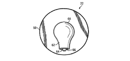
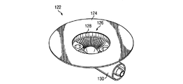
負圧アダプタ又はこれに付随するドレープに取り付けられた揮発性有機化合物(VOC)検出ストリップがある実施例で使用される。カラーパターンは、ある微生物の存在中で生産されることが知られている対象のVOCに曝されると、発現し、これによって、創傷流体中に存在する微生物の種類を同定する。図15及び16を参照すると、図2乃至9を参照して前述したように同様に、負圧アダプタ122は、基部124と、導管ハウジング130とを具えている。VOC検出パネル128は導管ハウジング130の凹部領域126中に配置されている。図16では、負圧アダプタ122は、半透明又は透明な特性の材料で構成されており、VOC検出パネル128を外部から視覚的に調べることができるとともに、負圧アダプタ122は創傷ドレッシングの分配マニホールドに対向する位置で基部124の所定の位置にある。従って、VOC検出パネル128は、図示するように凹部領域126の周縁部近くの凹部領域126内に配設されることが好ましい。図15は、創傷から引き入れられる流体物質に常時曝される凹部領域126内のVOC検出パネルの位置をさらに明瞭に示している。パネルは、創傷流体に十分に曝される限り、代替の位置にすることができる。
Used in embodiments where there is a volatile organic compound (VOC) detection strip attached to a negative pressure adapter or associated drape. A color pattern develops when exposed to a VOC of a subject known to be produced in the presence of certain microorganisms, thereby identifying the type of microorganism present in the wound fluid. Referring to FIGS. 15 and 16, the
本発明がかなりの利点を有して提供されることは、前記の事から明らかである。本発明は、数個の形でのみ示されているがこれに限定される物ではなく、本発明の範囲から外れることなく、様々な変更や改良をすることができる。 It is clear from the foregoing that the present invention is provided with considerable advantages. The present invention is shown only in a few forms, but is not limited thereto, and various changes and modifications can be made without departing from the scope of the present invention.
Claims (21)
入口面を規定する凹部領域を有する導管ハウジングと;
前記導管ハウジングを通って前記入口面上の主ポートと流体連通している主導管と;
前記組織部位における負圧を測定するために、前記導管ハウジングを通って前記入口面上の補助ポートと流体連通している少なくとも1つの補助導管と;
液体を前記補助ポートから離して前記主ポート内に向けるように前記入口面上に配置されたチャネルと;
前記導管ハウジングに取り付けられた基部であって、当該基部の開口が前記凹部領域を囲むように取り付けられている基部と;
前記基部の周辺部からの液体を前記補助導管から離すように前記基部上に配置された放射状のチャネルとを具えることを特徴とするアダプタ。 In a negative pressure adapter that couples a negative pressure source to a porous pad to apply negative pressure wound therapy to a tissue site, the adapter includes:
A conduit housing having a recessed region defining an inlet surface;
A main conduit in fluid communication with the main port on the inlet face through the conduit housing;
At least one auxiliary conduit in fluid communication with the auxiliary port on the inlet face through the conduit housing to measure negative pressure at the tissue site ;
A channel disposed on the inlet surface to direct liquid away from the auxiliary port and into the main port;
A base attached to the conduit housing, the base attached so that an opening in the base surrounds the recessed area;
An adapter comprising a radial channel disposed on the base to separate liquid from a periphery of the base from the auxiliary conduit.
液体を前記放射状のチャネル内に向けるように前記基部上に配置された中間収集チャネルを具えることを特徴とするアダプタ。The adapter of claim 1 further includes:
An adapter comprising an intermediate collection channel disposed on the base to direct liquid into the radial channel.
前記補助ポートが付随する前記凹部領域の半円部分に付随して配置された線形のチャネル部分と;
前記入口面の3分の1に沿った放射状のチャネル部分とを具えることを特徴とするアダプタ。The adapter of claim 3, wherein the channel is:
A linear channel portion disposed in association with a semicircular portion of the recessed region with which the auxiliary port is associated;
An adapter comprising a radial channel portion along one third of the inlet surface.
前記補助ポートが付随する前記凹部領域の半円部分に付随して配置された線形のチャネル部分と;
前記入口面の3分の1に沿った放射状のチャネル部分とを具えることを特徴とするアダプタ。The adapter of claim 1, wherein the channel is;
A linear channel portion disposed in association with a semicircular portion of the recessed region with which the auxiliary port is associated;
An adapter comprising a radial channel portion along one third of the inlet surface.
入口面を規定する凹部領域を有する導管ハウジングと;
前記導管ハウジングを通って前記入口面上の主ポートと流体連通する主導管と;
前記組織部位における負圧を測定するために、前記導管ハウジングを通って前記入口面上の補助ポートと流体連通する少なくとも1つの補助導管と;
液体を前記補助ポートから離して前記主ポート内に向けるように前記入口面上に配置されたチャネルと;
前記補助導管を支持して囲んでいる壁部分であって、内側面と、外側面と前記主ポートに向かって延在する前記外側面に沿ったガイド用チャネルとを有する壁部分とを具えることを特徴とするアダプタ。 In a negative pressure adapter that couples a negative pressure source to a porous pad for applying negative pressure wound therapy to a tissue site, the adapter includes:
A conduit housing having a recessed region defining an inlet surface;
A main conduit in fluid communication with the main port on the inlet face through the conduit housing;
At least one auxiliary conduit in fluid communication with the auxiliary port on the inlet face through the conduit housing to measure negative pressure at the tissue site ;
A channel disposed on the inlet surface to direct liquid away from the auxiliary port and into the main port;
A wall portion that supports and surrounds the auxiliary conduit, the wall portion having an inner surface, an outer surface, and a guide channel along the outer surface that extends toward the main port. An adapter characterized by that.
前記導管ハウジングに取り付けられた基部であって、当該基部の開口が前記凹部領域を囲むように取り付けられている基部を具えることを特徴とするアダプタ。15. The adapter according to claim 14, further comprising:
An adapter comprising a base attached to the conduit housing, the base being attached so that an opening in the base surrounds the recessed area.
前記導管ハウジングに取り付けられた基部であって、当該基部の開口が前記凹部領域を囲むように取り付けられている基部と;
前記基部の周辺部からの液体を前記補助導管から離すように前記基部上に配置された放射状のチャネルと;
液体を前記放射状のチャネル内に向けるように前記基部上に配置された中間収集チャネルとを具えることを特徴とするアダプタ。15. The adapter according to claim 14, further comprising:
A base attached to the conduit housing, the base attached so that an opening in the base surrounds the recessed area;
A radial channel disposed on the base to separate liquid from the periphery of the base from the auxiliary conduit;
An adapter comprising an intermediate collection channel disposed on the base to direct liquid into the radial channel.
前記補助ポートが付随する前記凹部領域の半円部分に付随して配置された線形のチャネル部分と;
前記入口面の3分の1に沿った放射状のチャネル部分とを具えることを特徴とするアダプタ。15. The adapter of claim 14, wherein the channel is;
A linear channel portion disposed in association with a semicircular portion of the recessed region with which the auxiliary port is associated;
An adapter comprising a radial channel portion along one third of the inlet surface.
Applications Claiming Priority (5)
| Application Number | Priority Date | Filing Date | Title |
|---|---|---|---|
| US76554806P | 2006-02-06 | 2006-02-06 | |
| US60/765,548 | 2006-02-06 | ||
| PCT/US2007/003065 WO2007092397A2 (en) | 2006-02-06 | 2007-02-06 | Systems and methods for improved connection to wound dressings in conjunction with reduced pressure wound treatment systems |
| US11/702,822 US7651484B2 (en) | 2006-02-06 | 2007-02-06 | Systems and methods for improved connection to wound dressings in conjunction with reduced pressure wound treatment systems |
| US11/702,822 | 2007-02-06 |
Publications (3)
| Publication Number | Publication Date |
|---|---|
| JP2009525776A JP2009525776A (en) | 2009-07-16 |
| JP2009525776A5 JP2009525776A5 (en) | 2010-12-24 |
| JP4719278B2 true JP4719278B2 (en) | 2011-07-06 |
Family
ID=38345717
Family Applications (1)
| Application Number | Title | Priority Date | Filing Date |
|---|---|---|---|
| JP2008553402A Active JP4719278B2 (en) | 2006-02-06 | 2007-02-06 | Adapter for applying negative pressure wound therapy to tissue sites |
Country Status (14)
| Country | Link |
|---|---|
| US (7) | US7651484B2 (en) |
| EP (5) | EP3533478B1 (en) |
| JP (1) | JP4719278B2 (en) |
| KR (1) | KR101045751B1 (en) |
| CN (2) | CN101378796B (en) |
| AU (2) | AU2007212480B2 (en) |
| BR (1) | BRPI0706893B8 (en) |
| CA (1) | CA2635617C (en) |
| HK (2) | HK1165346A1 (en) |
| IL (1) | IL193142A0 (en) |
| MX (1) | MX2008009755A (en) |
| RU (2) | RU2436597C2 (en) |
| WO (1) | WO2007092397A2 (en) |
| ZA (1) | ZA200807411B (en) |
Families Citing this family (210)
| Publication number | Priority date | Publication date | Assignee | Title |
|---|---|---|---|---|
| GB9523253D0 (en) * | 1995-11-14 | 1996-01-17 | Mediscus Prod Ltd | Portable wound treatment apparatus |
| GB9719520D0 (en) | 1997-09-12 | 1997-11-19 | Kci Medical Ltd | Surgical drape and suction heads for wound treatment |
| US8444611B2 (en) | 2003-07-22 | 2013-05-21 | Kci Licensing, Inc. | Negative pressure wound treatment dressing |
| US11298453B2 (en) | 2003-10-28 | 2022-04-12 | Smith & Nephew Plc | Apparatus and method for wound cleansing with actives |
| GB0508531D0 (en) | 2005-04-27 | 2005-06-01 | Smith & Nephew | Sai with ultrasound |
| SE0500061L (en) * | 2005-01-11 | 2006-07-12 | Moelnlycke Health Care Ab | Sealing film dressing |
| CN101257938A (en) | 2005-09-07 | 2008-09-03 | 泰科保健集团有限合伙公司 | Wound dressing with vacuum reservoir |
| KR101045751B1 (en) | 2006-02-06 | 2011-06-30 | 케이씨아이 라이센싱 인코포레이티드 | Systems and methods for improved connection to wound dressings in conjunction with reduced pressure wound treatment systems |
| SE0601536L (en) * | 2006-07-11 | 2008-01-12 | Moelnlycke Health Care Ab | Coil connection |
| GB0712735D0 (en) * | 2006-07-26 | 2007-08-08 | Smith & Nephew | Dressing |
| US9820888B2 (en) | 2006-09-26 | 2017-11-21 | Smith & Nephew, Inc. | Wound dressing |
| CA2872297C (en) | 2006-09-28 | 2016-10-11 | Smith & Nephew, Inc. | Portable wound therapy system |
| US7967810B2 (en) | 2006-10-20 | 2011-06-28 | Mary Beth Kelley | Sub-atmospheric wound-care system |
| US7880050B2 (en) | 2007-02-09 | 2011-02-01 | Kci Licensing, Inc. | Breathable interface system for topical reduced pressure |
| US10117977B2 (en) | 2007-03-14 | 2018-11-06 | The Board Of Trustees Of The Leland Stanford Junior University | Devices and methods for application of reduced pressure therapy |
| AU2008251426B2 (en) * | 2007-05-10 | 2013-10-10 | Solventum Intellectual Properties Company | Reduced pressure wound dressing having a wound contact surface with columnar protrusions |
| US8246590B2 (en) | 2007-10-11 | 2012-08-21 | Spiracur, Inc. | Closed incision negative pressure wound therapy device and methods of use |
| EP2987510B1 (en) * | 2007-11-21 | 2020-10-28 | T.J. Smith & Nephew Limited | Suction device and dressing |
| WO2009068666A2 (en) * | 2007-11-30 | 2009-06-04 | Coloplast A/S | Attachment device for wound drainage system |
| WO2009068665A1 (en) * | 2007-11-30 | 2009-06-04 | Coloplast A/S | Tube assembly for use in a wound drainage system |
| US11253399B2 (en) | 2007-12-06 | 2022-02-22 | Smith & Nephew Plc | Wound filling apparatuses and methods |
| GB0723872D0 (en) | 2007-12-06 | 2008-01-16 | Smith & Nephew | Apparatus for topical negative pressure therapy |
| GB0723852D0 (en) * | 2007-12-06 | 2008-01-16 | Smith & Nephew | Wound fillers |
| US20130096518A1 (en) * | 2007-12-06 | 2013-04-18 | Smith & Nephew Plc | Wound filling apparatuses and methods |
| GB0723874D0 (en) * | 2007-12-06 | 2008-01-16 | Smith & Nephew | Dressing |
| GB2455962A (en) | 2007-12-24 | 2009-07-01 | Ethicon Inc | Reinforced adhesive backing sheet, for plaster |
| US8377017B2 (en) | 2008-01-03 | 2013-02-19 | Kci Licensing, Inc. | Low-profile reduced pressure treatment system |
| DK2242522T3 (en) | 2008-01-08 | 2012-06-18 | Bluesky Medical Group Inc | Wound treatment with uninterrupted variable pressure and methods for controlling it |
| EP2252342B1 (en) * | 2008-02-14 | 2014-10-08 | Spiracur Inc. | Devices and methods for treatment of damaged tissue |
| US8372049B2 (en) | 2008-03-05 | 2013-02-12 | Kci Licensing, Inc. | Dressing and method for applying reduced pressure to and collecting and storing fluid from a tissue site |
| US8298200B2 (en) * | 2009-06-01 | 2012-10-30 | Tyco Healthcare Group Lp | System for providing continual drainage in negative pressure wound therapy |
| US20180369462A1 (en) * | 2008-03-07 | 2018-12-27 | Smith & Nephew, Inc. | System for providing wound dressing port and associated wound dressing |
| US8021347B2 (en) | 2008-07-21 | 2011-09-20 | Tyco Healthcare Group Lp | Thin film wound dressing |
| US9033942B2 (en) | 2008-03-07 | 2015-05-19 | Smith & Nephew, Inc. | Wound dressing port and associated wound dressing |
| US8945030B2 (en) | 2008-03-12 | 2015-02-03 | Bluesky Medical Group, Inc. | Negative pressure dressing and method of using same |
| EP2259724B8 (en) | 2008-03-13 | 2017-04-19 | KCI Licensing, Inc. | Systems for monitoring a pressure at a tissue site |
| BRPI0906527A2 (en) | 2008-04-04 | 2016-09-06 | 3Mm Innovative Properties Company | apparatus for applying bandages to wounds and medical bandages |
| GB0808376D0 (en) | 2008-05-08 | 2008-06-18 | Bristol Myers Squibb Co | Wound dressing |
| CA2731427C (en) | 2008-08-08 | 2020-01-28 | Tyco Healthcare Group Lp | Wound dressing of continuous fibers |
| GB0817796D0 (en) | 2008-09-29 | 2008-11-05 | Convatec Inc | wound dressing |
| US8158844B2 (en) | 2008-10-08 | 2012-04-17 | Kci Licensing, Inc. | Limited-access, reduced-pressure systems and methods |
| KR101028916B1 (en) * | 2008-11-12 | 2011-04-12 | 주식회사 대웅제약 | Medical Suction Apparatus |
| DK2358425T3 (en) * | 2008-11-25 | 2014-12-01 | Spiracur Inc | A device for the supply of reduced pressure on the body surfaces |
| US8721629B2 (en) * | 2008-12-02 | 2014-05-13 | Kci Licensing, Inc. | System and method for mechanical closure of wounds |
| US8708984B2 (en) * | 2008-12-24 | 2014-04-29 | Kci Licensing, Inc. | Reduced-pressure wound treatment systems and methods employing manifold structures |
| US8529528B2 (en) | 2008-12-24 | 2013-09-10 | Kci Licensing, Inc. | Reduced-pressure wound treatment systems and methods employing microstrain-inducing manifolds |
| KR20110107357A (en) | 2008-12-30 | 2011-09-30 | 케이씨아이 라이센싱 인코포레이티드 | Reduced pressure augmentation of microfracture procedures for cartilage repair |
| JP5628203B2 (en) | 2008-12-31 | 2014-11-19 | ケーシーアイ ライセンシング インコーポレイテッド | A system that induces fluid flow to stimulate tissue growth |
| TWI418374B (en) * | 2008-12-31 | 2013-12-11 | Ind Tech Res Inst | Wound treatment apparatus and guiding unit thereof |
| US9125766B2 (en) | 2008-12-31 | 2015-09-08 | Kci Licensing, Inc. | Tissue roll scaffolds |
| WO2010080907A1 (en) | 2009-01-07 | 2010-07-15 | Spiracur Inc. | Reduced pressure therapy of the sacral region |
| US8162907B2 (en) | 2009-01-20 | 2012-04-24 | Tyco Healthcare Group Lp | Method and apparatus for bridging from a dressing in negative pressure wound therapy |
| GB0902816D0 (en) | 2009-02-19 | 2009-04-08 | Smith & Nephew | Fluid communication path |
| WO2010102146A1 (en) * | 2009-03-04 | 2010-09-10 | Spiracur Inc. | Devices and methods to apply alternating level of reduced pressure to tissue |
| US8444614B2 (en) | 2009-04-10 | 2013-05-21 | Spiracur, Inc. | Methods and devices for applying closed incision negative pressure wound therapy |
| EP2416816B1 (en) | 2009-04-10 | 2014-10-15 | Spiracur Inc. | Methods and devices for applying closed incision negative pressure wound therapy |
| US8591485B2 (en) * | 2009-04-23 | 2013-11-26 | Prospera Technologies, LLC | System, method, and pump to prevent pump contamination during negative pressure wound therapy |
| SE533726C2 (en) | 2009-04-30 | 2010-12-14 | Moelnlycke Health Care Ab | Apparatus with negative pressure for treatment of wounds |
| US20100324516A1 (en) | 2009-06-18 | 2010-12-23 | Tyco Healthcare Group Lp | Apparatus for Vacuum Bridging and/or Exudate Collection |
| WO2011043863A2 (en) | 2009-08-13 | 2011-04-14 | Michael Simms Shuler | Methods and dressing systems for promoting healing of injured tissue |
| US20110054420A1 (en) * | 2009-08-27 | 2011-03-03 | Christopher Brian Locke | Reduced-pressure wound dressings and systems for re-epithelialization and granulation |
| US8690844B2 (en) * | 2009-08-27 | 2014-04-08 | Kci Licensing, Inc. | Re-epithelialization wound dressings and systems |
| CA2770874C (en) * | 2009-09-22 | 2017-01-03 | Moelnlycke Health Care Ab | An apparatus and method for controlling the negative pressure in a wound |
| KR101063342B1 (en) * | 2009-12-04 | 2011-09-07 | 주식회사 바이오알파 | Portable vacuum generator and medical suction device using same |
| WO2011087871A2 (en) | 2009-12-22 | 2011-07-21 | Smith & Nephew, Inc. | Apparatuses and methods for negative pressure wound therapy |
| DE102009060596A1 (en) * | 2009-12-23 | 2011-06-30 | Paul Hartmann Aktiengesellschaft, 89522 | Connection device for use in the vacuum treatment of wounds |
| AU2011207577B2 (en) | 2010-01-20 | 2015-11-26 | Solventum Intellectual Properties Company | Leak-resistant bandage systems and methods with hydrophilic foam wound insert for fluid-instillation and/or negative-pressure wound therapies |
| CA2786101C (en) | 2010-01-20 | 2018-08-07 | Kci Licensing, Inc. | Foam wound inserts with regions of higher and lower densities, wound dressings, and methods |
| AU2011207567B2 (en) * | 2010-01-20 | 2016-02-04 | Solventum Intellectual Properties Company | Wound-connection pads for fluid instillation and negative pressure wound therapy, and systems and methods |
| AU2011207543A1 (en) | 2010-01-22 | 2012-07-26 | Kci Licensing, Inc. | Devices, systems, and methods for instillation of foamed fluid with negative pressure wound therapy |
| WO2011094410A2 (en) * | 2010-01-29 | 2011-08-04 | Kci Licensing, Inc | Wound treatment apparatuses and methods for controlled delivery of fluids to a wound |
| US8791315B2 (en) | 2010-02-26 | 2014-07-29 | Smith & Nephew, Inc. | Systems and methods for using negative pressure wound therapy to manage open abdominal wounds |
| US8469935B2 (en) * | 2010-03-11 | 2013-06-25 | Kci Licensing, Inc. | Abdominal treatment systems, delivery devices, and methods |
| US8814842B2 (en) * | 2010-03-16 | 2014-08-26 | Kci Licensing, Inc. | Delivery-and-fluid-storage bridges for use with reduced-pressure systems |
| US8702665B2 (en) * | 2010-04-16 | 2014-04-22 | Kci Licensing, Inc. | Reduced-pressure sources, systems, and methods employing a polymeric, porous, hydrophobic material |
| GB201006988D0 (en) * | 2010-04-27 | 2010-06-09 | Smith & Nephew | Suction port |
| GB201006986D0 (en) * | 2010-04-27 | 2010-06-09 | Smith & Nephew | Wound dressing |
| US9061095B2 (en) | 2010-04-27 | 2015-06-23 | Smith & Nephew Plc | Wound dressing and method of use |
| USRE48117E1 (en) | 2010-05-07 | 2020-07-28 | Smith & Nephew, Inc. | Apparatuses and methods for negative pressure wound therapy |
| CN101829391A (en) * | 2010-05-16 | 2010-09-15 | 崇阳县天南星实业有限责任公司 | Medical drainage sucking disc and preparation method thereof |
| US20110306944A1 (en) * | 2010-06-14 | 2011-12-15 | Chean-Shui Chen | Milk collecting bottle for hand expression |
| GB201011173D0 (en) | 2010-07-02 | 2010-08-18 | Smith & Nephew | Provision of wound filler |
| TR201901104T4 (en) * | 2010-07-16 | 2019-02-21 | Kci Licensing Inc | System for interfacing with a reduced pressure winding. |
| US8753322B2 (en) | 2010-08-10 | 2014-06-17 | Spiracur Inc. | Controlled negative pressure apparatus and alarm mechanism |
| US8795246B2 (en) | 2010-08-10 | 2014-08-05 | Spiracur Inc. | Alarm system |
| GB201015656D0 (en) | 2010-09-20 | 2010-10-27 | Smith & Nephew | Pressure control apparatus |
| GB201020005D0 (en) | 2010-11-25 | 2011-01-12 | Smith & Nephew | Composition 1-1 |
| MX337627B (en) | 2010-11-25 | 2016-03-10 | Smith & Nephew | Composition i-ii and products and uses thereof. |
| GB201020236D0 (en) | 2010-11-30 | 2011-01-12 | Convatec Technologies Inc | A composition for detecting biofilms on viable tissues |
| CN103347562B (en) | 2010-12-08 | 2016-08-10 | 康沃特克科技公司 | Wound exudate system accessory |
| WO2012078781A1 (en) | 2010-12-08 | 2012-06-14 | Convatec Technologies Inc. | Integrated system for assessing wound exudates |
| WO2012087376A1 (en) | 2010-12-22 | 2012-06-28 | Smith & Nephew, Inc. | Apparatuses and methods for negative pressure wound therapy |
| USD714433S1 (en) | 2010-12-22 | 2014-09-30 | Smith & Nephew, Inc. | Suction adapter |
| GB2488749A (en) | 2011-01-31 | 2012-09-12 | Systagenix Wound Man Ip Co Bv | Laminated silicone coated wound dressing |
| US9421132B2 (en) | 2011-02-04 | 2016-08-23 | University Of Massachusetts | Negative pressure wound closure device |
| US9226737B2 (en) | 2011-02-04 | 2016-01-05 | University Of Massachusetts | Negative pressure wound closure device |
| GB201106491D0 (en) | 2011-04-15 | 2011-06-01 | Systagenix Wound Man Ip Co Bv | Patterened silicone coating |
| US9168179B2 (en) | 2011-06-24 | 2015-10-27 | Kci Licensing, Inc. | Reduced-pressure dressings employing tissue-fixation elements |
| EP3281652A1 (en) * | 2011-07-26 | 2018-02-14 | KCI Licensing, Inc. | Systems for treating a tissue site with reduced pressure involving a reduced-pressure interface having a multi-lumen conduit for contacting a manifold |
| GB201115182D0 (en) | 2011-09-02 | 2011-10-19 | Trio Healthcare Ltd | Skin contact material |
| US9393354B2 (en) | 2011-11-01 | 2016-07-19 | J&M Shuler Medical, Inc. | Mechanical wound therapy for sub-atmospheric wound care system |
| US9084845B2 (en) | 2011-11-02 | 2015-07-21 | Smith & Nephew Plc | Reduced pressure therapy apparatuses and methods of using same |
| BR112014010647A2 (en) * | 2011-11-02 | 2017-04-25 | Smith & Nephew | pressure therapy devices and methods of use thereof |
| US20150159066A1 (en) | 2011-11-25 | 2015-06-11 | Smith & Nephew Plc | Composition, apparatus, kit and method and uses thereof |
| GB2497406A (en) | 2011-11-29 | 2013-06-12 | Webtec Converting Llc | Dressing with a perforated binder layer |
| GB201120693D0 (en) | 2011-12-01 | 2012-01-11 | Convatec Technologies Inc | Wound dressing for use in vacuum therapy |
| JP6320930B2 (en) | 2011-12-16 | 2018-05-09 | ケーシーアイ ライセンシング インコーポレイテッド | Peelable medical drape |
| US10940047B2 (en) | 2011-12-16 | 2021-03-09 | Kci Licensing, Inc. | Sealing systems and methods employing a hybrid switchable drape |
| MX351280B (en) * | 2012-01-18 | 2017-10-06 | Worldwide Innovative Healthcare Inc | Modifiable occlusive skin dressing. |
| EP2636417B1 (en) * | 2012-03-05 | 2017-04-26 | Lohmann & Rauscher GmbH | Wound treatment assembly and covering device for same |
| US10070994B2 (en) | 2012-05-22 | 2018-09-11 | Smith & Nephew Plc | Apparatuses and methods for wound therapy |
| CN107280857A (en) | 2012-05-22 | 2017-10-24 | 史密夫及内修公开有限公司 | Wound healing device |
| EP3650055A1 (en) | 2012-05-23 | 2020-05-13 | Smith & Nephew plc | Apparatuses and methods for negative pressure wound therapy |
| US10117782B2 (en) | 2012-05-24 | 2018-11-06 | Smith & Nephew, Inc. | Devices and methods for treating and closing wounds with negative pressure |
| US9962295B2 (en) | 2012-07-16 | 2018-05-08 | Smith & Nephew, Inc. | Negative pressure wound closure device |
| EP2879635A2 (en) | 2012-08-01 | 2015-06-10 | Smith & Nephew PLC | Wound dressing and method of treatment |
| DK2879636T3 (en) | 2012-08-01 | 2017-06-19 | Smith & Nephew | Wound dressing |
| US8981528B2 (en) | 2012-11-16 | 2015-03-17 | Vishay General Semiconductor Llc | GaN-based Schottky diode having partially recessed anode |
| US8981381B2 (en) | 2012-11-16 | 2015-03-17 | Vishay General Semiconductor Llc | GaN-based Schottky diode having dual metal, partially recessed electrode |
| US9018698B2 (en) | 2012-11-16 | 2015-04-28 | Vishay General Semiconductor Llc | Trench-based device with improved trench protection |
| EP4279094A3 (en) | 2012-11-16 | 2024-02-28 | 3M Innovative Properties Company | Medical drape with pattern adhesive layers |
| GB201222770D0 (en) | 2012-12-18 | 2013-01-30 | Systagenix Wound Man Ip Co Bv | Wound dressing with adhesive margin |
| US20150354096A1 (en) | 2012-12-20 | 2015-12-10 | Convatec Technologies Inc. | Processing of chemically modified cellulosic fibres |
| USD738487S1 (en) | 2013-01-28 | 2015-09-08 | Molnlycke Health Care Ab | Suction device for negative pressure therapy |
| CA2902776C (en) | 2013-03-13 | 2023-03-07 | Smith & Nephew Inc. | Wound treatment apparatus and use thereof |
| RU2015142877A (en) | 2013-03-14 | 2017-04-18 | СМИТ ЭНД НЕФЬЮ ПиЭлСи | COMPRESSIBLE WOUND FILLERS AND SYSTEMS AND WAYS OF THEIR APPLICATION IN THE TREATMENT OF THE RAS WITH APPLICATION OF NEGATIVE PRESSURE |
| BR112015020855A2 (en) | 2013-03-15 | 2017-07-18 | Smith & Nephew | wound dressing and treatment method |
| US8939951B1 (en) * | 2013-03-15 | 2015-01-27 | James G. Getsay | Fluid collection device |
| US20160120706A1 (en) | 2013-03-15 | 2016-05-05 | Smith & Nephew Plc | Wound dressing sealant and use thereof |
| AU2014266943B2 (en) | 2013-05-10 | 2018-03-01 | Smith & Nephew Plc | Fluidic connector for irrigation and aspiration of wounds |
| BR112016007156B1 (en) * | 2013-10-02 | 2022-12-13 | 3M Innovative Properties Company | REDUCED PRESSURE SYSTEM |
| AU2014340232B2 (en) | 2013-10-21 | 2019-07-11 | Smith & Nephew Inc. | Negative pressure wound closure device |
| US10946124B2 (en) | 2013-10-28 | 2021-03-16 | Kci Licensing, Inc. | Hybrid sealing tape |
| US10016544B2 (en) | 2013-10-30 | 2018-07-10 | Kci Licensing, Inc. | Dressing with differentially sized perforations |
| WO2015065616A1 (en) | 2013-10-30 | 2015-05-07 | Kci Licensing, Inc. | Dressing with sealing and retention intereface |
| EP3062833B1 (en) * | 2013-10-30 | 2019-04-17 | KCI Licensing, Inc. | Absorbent conduit and system |
| EP3513773A1 (en) | 2013-10-30 | 2019-07-24 | KCI Licensing, Inc. | Condensate absorbing and dissipating system |
| RU2016133735A (en) | 2014-01-21 | 2018-02-28 | СМИТ ЭНД НЕФЬЮ ПиЭлСи | COMPRESSIVE BANDAGE FOR TREATMENT OF Wounds by NEGATIVE PRESSURE |
| WO2015130471A1 (en) | 2014-02-28 | 2015-09-03 | Kci Licensing, Inc. | Hybrid drape having a gel-coated perforated mesh |
| US11026844B2 (en) | 2014-03-03 | 2021-06-08 | Kci Licensing, Inc. | Low profile flexible pressure transmission conduit |
| WO2015164801A1 (en) * | 2014-04-25 | 2015-10-29 | Burdick Steven | Vacuum wound device |
| WO2015168681A1 (en) | 2014-05-02 | 2015-11-05 | Kci Licensing, Inc. | Fluid storage devices, systems, and methods |
| EP3854361B8 (en) | 2014-06-05 | 2024-03-27 | Solventum Intellectual Properties Company | Dressing with fluid acquisition and distribution characteristics |
| USD758572S1 (en) * | 2014-06-20 | 2016-06-07 | Integrated Healing Technologies, Llc. | Wound drain dome |
| CA2955060A1 (en) * | 2014-08-11 | 2016-02-18 | Kci Licensing, Inc. | Protease modulating wound interface layer for use with negative pressure wound therapy |
| AU2015360377B2 (en) * | 2014-12-10 | 2020-09-24 | Worldwide Innovative Healthcare, Inc. | Unbacked and modifiable tapes and skin dressings |
| EP3233001B1 (en) | 2014-12-17 | 2020-06-17 | KCI Licensing, Inc. | Dressing with offloading capability |
| DE102014227041A1 (en) | 2014-12-30 | 2016-06-30 | Paul Hartmann Ag | Connection device for use in the negative pressure therapy of wounds |
| DE102014227042A1 (en) | 2014-12-30 | 2016-06-30 | Paul Hartmann Ag | Connection device for use in the negative pressure therapy of wounds |
| EP3288509B1 (en) | 2015-04-29 | 2022-06-29 | Smith & Nephew, Inc | Negative pressure wound closure device |
| EP3294245B1 (en) | 2015-05-08 | 2019-09-04 | KCI Licensing, Inc. | Low acuity dressing with integral pump |
| US10076594B2 (en) | 2015-05-18 | 2018-09-18 | Smith & Nephew Plc | Fluidic connector for negative pressure wound therapy |
| JP2018519943A (en) * | 2015-07-14 | 2018-07-26 | ケーシーアイ ライセンシング インコーポレイテッド | Medical dressing interface device, system, and method |
| US10583228B2 (en) | 2015-07-28 | 2020-03-10 | J&M Shuler Medical, Inc. | Sub-atmospheric wound therapy systems and methods |
| US20170028111A1 (en) | 2015-07-29 | 2017-02-02 | Innovative Therapies, Inc. | Wound therapy device pressure monitoring and control system |
| US11096830B2 (en) | 2015-09-01 | 2021-08-24 | Kci Licensing, Inc. | Dressing with increased apposition force |
| WO2017048866A1 (en) | 2015-09-17 | 2017-03-23 | Kci Licensing, Inc. | Hybrid silicone and acrylic adhesive cover for use with wound treatment |
| DE102015224746A1 (en) * | 2015-12-09 | 2017-06-14 | Paul Hartmann Ag | Connection device for use in the negative pressure therapy of wounds |
| US10814049B2 (en) | 2015-12-15 | 2020-10-27 | University Of Massachusetts | Negative pressure wound closure devices and methods |
| US10575991B2 (en) | 2015-12-15 | 2020-03-03 | University Of Massachusetts | Negative pressure wound closure devices and methods |
| CN105497995A (en) * | 2015-12-29 | 2016-04-20 | 昆山韦睿医疗科技有限公司 | Manual negative pressure treatment device |
| CN109069708B (en) | 2016-03-04 | 2022-04-12 | 史密夫及内修公开有限公司 | Negative pressure wound therapy device for wounds after breast surgery |
| US11740241B2 (en) | 2016-03-30 | 2023-08-29 | Synovo Gmbh | Construct including an anchor, an enzyme recognition site and an indicator region for detecting microbial infection in wounds |
| CN109310528B (en) | 2016-03-30 | 2021-07-20 | 康沃特克科技公司 | Detecting microbial infection in a wound |
| JP7071957B2 (en) | 2016-07-08 | 2022-05-19 | コンバテック・テクノロジーズ・インコーポレイテッド | Flexible negative pressure system |
| CA3030153C (en) | 2016-07-08 | 2023-10-24 | Convatec Technologies Inc. | Fluid flow sensing |
| CA3030151A1 (en) | 2016-07-08 | 2018-01-11 | Convatec Technologies Inc. | Fluid collection apparatus |
| EP3528861A4 (en) * | 2016-10-19 | 2020-06-17 | Medtec Medical, Inc. | Electronic vacuum regulator device |
| CN108295321A (en) * | 2017-01-13 | 2018-07-20 | 厦门圣慈医疗器材有限公司 | sucker |
| CN108294864A (en) * | 2017-01-13 | 2018-07-20 | 厦门圣慈医疗器材有限公司 | sucker |
| TWI621453B (en) * | 2017-01-13 | 2018-04-21 | 廈門聖慈醫療器材有限公司 | Suction disc |
| TWI629072B (en) * | 2017-01-13 | 2018-07-11 | 廈門聖慈醫療器材有限公司 | Suction disc |
| AU201716716S (en) | 2017-05-11 | 2017-11-21 | MAƒA¶LNLYCKE HEALTH CARE AB | Wound dressings |
| WO2019083966A1 (en) | 2017-10-26 | 2019-05-02 | Kci Licensing, Inc. | Negative pressure wound therapy device with automated filter purging |
| US20200338245A1 (en) | 2017-10-26 | 2020-10-29 | Kci Licensing, Inc. | Negative pressure wound therapy canister |
| GB201718014D0 (en) | 2017-11-01 | 2017-12-13 | Smith & Nephew | Dressing for negative pressure wound therapy with filter |
| US11754063B2 (en) | 2018-01-02 | 2023-09-12 | Kci Licensing, Inc. | Negative pressure wound therapy device with silent piezoelectric pump |
| US11554206B2 (en) | 2018-02-01 | 2023-01-17 | Kci Licensing, Inc. | Negative pressure wound therapy device using a vacuum generating pump providing audible therapy feedback |
| CN111936177A (en) * | 2018-03-29 | 2020-11-13 | 凯希特许有限公司 | Wound therapy system with wound volume estimation |
| USD867907S1 (en) | 2018-04-12 | 2019-11-26 | Kci Licensing, Inc. | Cutting template |
| USD886648S1 (en) | 2018-04-12 | 2020-06-09 | Kci Licensing, Inc. | Cutting template |
| WO2019199687A1 (en) | 2018-04-13 | 2019-10-17 | Kci Licensing, Inc. | Method to dynamically measure apposition and patient limb movement in a negative pressure closed incision dressing |
| US11701264B2 (en) | 2018-06-27 | 2023-07-18 | Kci Licensing, Inc. | Wound therapy system with wound volume estimation using geometric approximation |
| GB201811449D0 (en) | 2018-07-12 | 2018-08-29 | Smith & Nephew | Apparatuses and methods for negative pressure wound therapy |
| EP3823685B1 (en) | 2018-07-16 | 2023-03-15 | KCI Licensing, Inc. | Wound therapy system with conduit blockage detection |
| EP3829667A1 (en) | 2018-08-03 | 2021-06-09 | KCI Licensing, Inc. | Wound therapy system with wound volume estimation |
| EP4302790A3 (en) | 2018-08-21 | 2024-03-27 | Solventum Intellectual Properties Company | System for utilizing pressure decay to determine available fluid capacity in a negative pressure dressing |
| EP3873551A1 (en) | 2018-11-02 | 2021-09-08 | KCI Licensing, Inc. | Wound therapy tubeset system for wound volume estimation |
| US20220001100A1 (en) | 2018-11-14 | 2022-01-06 | Kci Licensing, Inc. | Wound therapy system with blockage and leak detection |
| WO2020124038A1 (en) | 2018-12-13 | 2020-06-18 | University Of Massachusetts | Negative pressure wound closure devices and methods |
| CA3128274A1 (en) * | 2019-02-06 | 2020-08-13 | Kci Licensing, Inc. | Wound therapy system with internal alternating orifice |
| WO2020185241A1 (en) | 2019-03-11 | 2020-09-17 | Kci Licensing, Inc. | Wound therapy system with fluid canister volume detection |
| US11471573B2 (en) * | 2019-03-27 | 2022-10-18 | Kci Licensing, Inc. | Wound therapy system with wound volume estimation |
| CN113613692A (en) | 2019-03-27 | 2021-11-05 | 凯希特许有限公司 | Wound therapy system with wound volume estimation |
| CN113573748A (en) | 2019-03-27 | 2021-10-29 | 凯希特许有限公司 | Wound therapy system with wound volume estimation |
| GB201910500D0 (en) * | 2019-07-23 | 2019-09-04 | Smith & Nephew | Apparatuses and methods for negative pressure wound therapy |
| US20220304594A1 (en) | 2019-08-23 | 2022-09-29 | Kci Licensing, Inc. | Systems and methods for determining and tracking range of motion of a jointed limb |
| EP4021525A1 (en) * | 2019-08-30 | 2022-07-06 | KCI Licensing, Inc. | Dressing interface with micro-needles for negative-pressure treatment |
| US20220370255A1 (en) | 2019-10-08 | 2022-11-24 | Kci Licensing, Inc. | Dressing for breast cavities |
| RU2734443C1 (en) * | 2019-11-05 | 2020-10-16 | Общество с ограниченной ответственностью "ВИТ-Медикал" | Device for treating infected and purulent wounds |
| US11771819B2 (en) | 2019-12-27 | 2023-10-03 | Convatec Limited | Low profile filter devices suitable for use in negative pressure wound therapy systems |
| US11331221B2 (en) | 2019-12-27 | 2022-05-17 | Convatec Limited | Negative pressure wound dressing |
| WO2021140467A1 (en) | 2020-01-08 | 2021-07-15 | Kci Licensing, Inc. | Dressing with optional wound status indicator |
| US11160917B2 (en) | 2020-01-22 | 2021-11-02 | J&M Shuler Medical Inc. | Negative pressure wound therapy barrier |
| WO2021209949A1 (en) | 2020-04-16 | 2021-10-21 | Kci Licensing, Inc. | Systems and methods for active evaporation of a wound therapy system |
| USD951428S1 (en) * | 2020-05-11 | 2022-05-10 | Xiamen Suneetek Medical Equipment Co., Ltd. | Suction disk for negative pressure wound therapy |
| WO2022263938A1 (en) | 2021-06-15 | 2022-12-22 | Kci Manufacturing Unlimited Company | Fistula ring |
| WO2023062465A1 (en) | 2021-10-13 | 2023-04-20 | Kci Manufacturing Unlimited Company | Systems and methods for detecting negative pressure wound therapy dressing leakage using stethoscope |
| WO2023067416A1 (en) | 2021-10-22 | 2023-04-27 | Kci Manufacturing Unlimited Company | Negative pressure wound therapy and phototherapy |
| WO2023079378A1 (en) | 2021-11-03 | 2023-05-11 | Kci Manufacturing Unlimited Company | Systems and methods for negative pressure wound therapy system with noise cancelling |
Citations (2)
| Publication number | Priority date | Publication date | Assignee | Title |
|---|---|---|---|---|
| JPS6376845A (en) * | 1986-09-20 | 1988-04-07 | Fujitsu Ltd | Vibration-proof magnetic material and its production |
| WO2005105180A1 (en) * | 2004-04-28 | 2005-11-10 | Smith & Nephew, Plc | Apparatus for aspirating, irrigating and/or cleansing of wounds |
Family Cites Families (245)
| Publication number | Priority date | Publication date | Assignee | Title |
|---|---|---|---|---|
| US1355846A (en) | 1920-02-06 | 1920-10-19 | David A Rannells | Medical appliance |
| US2305289A (en) * | 1939-06-17 | 1942-12-15 | Coburg Hermann | Surgical appliance |
| US2547758A (en) | 1949-01-05 | 1951-04-03 | Wilmer B Keeling | Instrument for treating the male urethra |
| US2632443A (en) | 1949-04-18 | 1953-03-24 | Eleanor P Lesher | Surgical dressing |
| GB692578A (en) | 1949-09-13 | 1953-06-10 | Minnesota Mining & Mfg | Improvements in or relating to drape sheets for surgical use |
| US2682873A (en) | 1952-07-30 | 1954-07-06 | Johnson & Johnson | General purpose protective dressing |
| NL189176B (en) | 1956-07-13 | 1900-01-01 | Hisamitsu Pharmaceutical Co | PLASTER BASED ON A SYNTHETIC RUBBER. |
| US2969057A (en) | 1957-11-04 | 1961-01-24 | Brady Co W H | Nematodic swab |
| US3026874A (en) | 1959-11-06 | 1962-03-27 | Robert C Stevens | Wound shield |
| US3066672A (en) | 1960-09-27 | 1962-12-04 | Jr William H Crosby | Method and apparatus for serial sampling of intestinal juice |
| US3089492A (en) | 1961-05-11 | 1963-05-14 | Owens Neal | Wet surgical dressing |
| US3142298A (en) | 1962-01-29 | 1964-07-28 | William L Koski | Stomach pump apparatus |
| US3382867A (en) | 1965-03-22 | 1968-05-14 | Ruby L. Reaves | Body portion developing device with combined vacuum and vibrating means |
| US3367332A (en) | 1965-08-27 | 1968-02-06 | Gen Electric | Product and process for establishing a sterile area of skin |
| US3520300A (en) | 1967-03-15 | 1970-07-14 | Amp Inc | Surgical sponge and suction device |
| US3568675A (en) * | 1968-08-30 | 1971-03-09 | Clyde B Harvey | Fistula and penetrating wound dressing |
| US3682180A (en) | 1970-06-08 | 1972-08-08 | Coilform Co Inc | Drain clip for surgical drain |
| BE789293Q (en) | 1970-12-07 | 1973-01-15 | Parke Davis & Co | MEDICO-SURGICAL DRESSING FOR BURNS AND SIMILAR LESIONS |
| US3826254A (en) | 1973-02-26 | 1974-07-30 | Verco Ind | Needle or catheter retaining appliance |
| DE2527706A1 (en) | 1975-06-21 | 1976-12-30 | Hanfried Dr Med Weigand | DEVICE FOR THE INTRODUCTION OF CONTRAST AGENTS INTO AN ARTIFICIAL INTESTINAL OUTLET |
| DE2640413C3 (en) | 1976-09-08 | 1980-03-27 | Richard Wolf Gmbh, 7134 Knittlingen | Catheter monitor |
| NL7710909A (en) | 1976-10-08 | 1978-04-11 | Smith & Nephew | COMPOSITE STRAPS. |
| GB1562244A (en) | 1976-11-11 | 1980-03-05 | Lock P M | Wound dressing materials |
| US4080970A (en) | 1976-11-17 | 1978-03-28 | Miller Thomas J | Post-operative combination dressing and internal drain tube with external shield and tube connector |
| US4139004A (en) | 1977-02-17 | 1979-02-13 | Gonzalez Jr Harry | Bandage apparatus for treating burns |
| US4184510A (en) | 1977-03-15 | 1980-01-22 | Fibra-Sonics, Inc. | Valued device for controlling vacuum in surgery |
| US4165748A (en) | 1977-11-07 | 1979-08-28 | Johnson Melissa C | Catheter tube holder |
| US4256109A (en) | 1978-07-10 | 1981-03-17 | Nichols Robert L | Shut off valve for medical suction apparatus |
| SE414994B (en) | 1978-11-28 | 1980-09-01 | Landstingens Inkopscentral | VENKATETERFORBAND |
| BR7908937A (en) | 1978-12-06 | 1981-06-30 | Svedman Paul | DEVICE FOR TREATING FABRICS, FOR EXAMPLE, SKIN |
| US4250882A (en) * | 1979-01-26 | 1981-02-17 | Medical Dynamics, Inc. | Wound drainage device |
| US4266545A (en) | 1979-04-06 | 1981-05-12 | Moss James P | Portable suction device for collecting fluids from a closed wound |
| US4342745A (en) | 1979-05-31 | 1982-08-03 | Zyma S.A. | Use of polyvinyl alcohols for the treatment of lesions |
| US4284079A (en) | 1979-06-28 | 1981-08-18 | Adair Edwin Lloyd | Method for applying a male incontinence device |
| US4261360A (en) | 1979-11-05 | 1981-04-14 | Urethral Devices Research, Inc. | Transurethral irrigation pressure controller |
| US4261363A (en) | 1979-11-09 | 1981-04-14 | C. R. Bard, Inc. | Retention clips for body fluid drains |
| US4569348A (en) | 1980-02-22 | 1986-02-11 | Velcro Usa Inc. | Catheter tube holder strap |
| ATE14835T1 (en) | 1980-03-11 | 1985-08-15 | Schmid Eduard | SKIN GRAFT PRESSURE BANDAGE. |
| US4297995A (en) | 1980-06-03 | 1981-11-03 | Key Pharmaceuticals, Inc. | Bandage containing attachment post |
| US4333468A (en) | 1980-08-18 | 1982-06-08 | Geist Robert W | Mesentery tube holder apparatus |
| US4465485A (en) | 1981-03-06 | 1984-08-14 | Becton, Dickinson And Company | Suction canister with unitary shut-off valve and filter features |
| US4392853A (en) | 1981-03-16 | 1983-07-12 | Rudolph Muto | Sterile assembly for protecting and fastening an indwelling device |
| US4433972A (en) * | 1981-06-01 | 1984-02-28 | Amanda Malfitano | Sanitary napkin |
| US4373519A (en) | 1981-06-26 | 1983-02-15 | Minnesota Mining And Manufacturing Company | Composite wound dressing |
| US4392858A (en) | 1981-07-16 | 1983-07-12 | Sherwood Medical Company | Wound drainage device |
| US4419097A (en) | 1981-07-31 | 1983-12-06 | Rexar Industries, Inc. | Attachment for catheter tube |
| AU550575B2 (en) | 1981-08-07 | 1986-03-27 | Richard Christian Wright | Wound drainage device |
| SE429197B (en) | 1981-10-14 | 1983-08-22 | Frese Nielsen | SAR TREATMENT DEVICE |
| US4460368A (en) * | 1981-10-29 | 1984-07-17 | Almedco, Inc. | Trans-dermal medication system |
| DE3146266A1 (en) | 1981-11-21 | 1983-06-01 | B. Braun Melsungen Ag, 3508 Melsungen | COMBINED DEVICE FOR A MEDICAL SUCTION DRAINAGE |
| US4433973A (en) | 1982-01-12 | 1984-02-28 | Bioresearch Inc. | Reusable tube connector assembly |
| US4551139A (en) | 1982-02-08 | 1985-11-05 | Marion Laboratories, Inc. | Method and apparatus for burn wound treatment |
| US4444545A (en) | 1982-04-08 | 1984-04-24 | Sanders David F | Pump control system |
| US4475909A (en) | 1982-05-06 | 1984-10-09 | Eisenberg Melvin I | Male urinary device and method for applying the device |
| EP0100148B1 (en) | 1982-07-06 | 1986-01-08 | Dow Corning Limited | Medical-surgical dressing and a process for the production thereof |
| US4534356A (en) | 1982-07-30 | 1985-08-13 | Diamond Shamrock Chemicals Company | Solid state transcutaneous blood gas sensors |
| NZ206837A (en) | 1983-01-27 | 1986-08-08 | Johnson & Johnson Prod Inc | Thin film adhesive dressing:backing material in three sections |
| US4795435A (en) | 1983-02-25 | 1989-01-03 | E. R. Squibb & Sons, Inc. | Device for protecting a wound |
| US4533352A (en) | 1983-03-07 | 1985-08-06 | Pmt Inc. | Microsurgical flexible suction mat |
| US4548202A (en) | 1983-06-20 | 1985-10-22 | Ethicon, Inc. | Mesh tissue fasteners |
| US4540412A (en) | 1983-07-14 | 1985-09-10 | The Kendall Company | Device for moist heat therapy |
| US4543100A (en) | 1983-11-01 | 1985-09-24 | Brodsky Stuart A | Catheter and drain tube retainer |
| US4468219A (en) | 1983-12-20 | 1984-08-28 | International Business Machines Corporation | Pump flow rate compensation system |
| US4525374A (en) | 1984-02-27 | 1985-06-25 | Manresa, Inc. | Treating hydrophobic filters to render them hydrophilic |
| GB2157958A (en) | 1984-05-03 | 1985-11-06 | Ernest Edward Austen Bedding | Ball game net support |
| US4897081A (en) | 1984-05-25 | 1990-01-30 | Thermedics Inc. | Percutaneous access device |
| US5215522A (en) | 1984-07-23 | 1993-06-01 | Ballard Medical Products | Single use medical aspirating device and method |
| GB8419745D0 (en) | 1984-08-02 | 1984-09-05 | Smith & Nephew Ass | Wound dressing |
| US4872450A (en) | 1984-08-17 | 1989-10-10 | Austad Eric D | Wound dressing and method of forming same |
| US4655754A (en) | 1984-11-09 | 1987-04-07 | Stryker Corporation | Vacuum wound drainage system and lipids baffle therefor |
| US4826494A (en) | 1984-11-09 | 1989-05-02 | Stryker Corporation | Vacuum wound drainage system |
| US4605399A (en) | 1984-12-04 | 1986-08-12 | Complex, Inc. | Transdermal infusion device |
| US5037397A (en) | 1985-05-03 | 1991-08-06 | Medical Distributors, Inc. | Universal clamp |
| US4640688A (en) | 1985-08-23 | 1987-02-03 | Mentor Corporation | Urine collection catheter |
| US4710165A (en) | 1985-09-16 | 1987-12-01 | Mcneil Charles B | Wearable, variable rate suction/collection device |
| US4758220A (en) | 1985-09-26 | 1988-07-19 | Alcon Laboratories, Inc. | Surgical cassette proximity sensing and latching apparatus |
| US4733659A (en) | 1986-01-17 | 1988-03-29 | Seton Company | Foam bandage |
| EP0256060A1 (en) | 1986-01-31 | 1988-02-24 | OSMOND, Roger L. W. | Suction system for wound and gastro-intestinal drainage |
| US4838883A (en) | 1986-03-07 | 1989-06-13 | Nissho Corporation | Urine-collecting device |
| US5266071A (en) | 1986-03-28 | 1993-11-30 | Nancy W. Elftman | Method for using percutaneous accessport |
| JPS62281965A (en) | 1986-05-29 | 1987-12-07 | テルモ株式会社 | Catheter and catheter fixing member |
| GB8621884D0 (en) | 1986-09-11 | 1986-10-15 | Bard Ltd | Catheter applicator |
| GB2195255B (en) | 1986-09-30 | 1991-05-01 | Vacutec Uk Limited | Apparatus for vacuum treatment of an epidermal surface |
| US4743232A (en) | 1986-10-06 | 1988-05-10 | The Clinipad Corporation | Package assembly for plastic film bandage |
| DE3634569A1 (en) | 1986-10-10 | 1988-04-21 | Sachse Hans E | CONDOM CATHETER, A URINE TUBE CATHETER FOR PREVENTING RISING INFECTIONS |
| JPS63135179A (en) | 1986-11-26 | 1988-06-07 | 立花 俊郎 | Subcataneous drug administration set |
| GB8628564D0 (en) | 1986-11-28 | 1987-01-07 | Smiths Industries Plc | Anti-foaming agent suction apparatus |
| GB8706116D0 (en) | 1987-03-14 | 1987-04-15 | Smith & Nephew Ass | Adhesive dressings |
| US4787888A (en) | 1987-06-01 | 1988-11-29 | University Of Connecticut | Disposable piezoelectric polymer bandage for percutaneous delivery of drugs and method for such percutaneous delivery (a) |
| EP0300621B1 (en) | 1987-06-22 | 1990-12-27 | Takeda Chemical Industries, Ltd. | Suction equipment for medical operation |
| JPH0767455B2 (en) * | 1987-06-22 | 1995-07-26 | 平和物産株式会社 | Surgical aid |
| US4863449A (en) | 1987-07-06 | 1989-09-05 | Hollister Incorporated | Adhesive-lined elastic condom cathether |
| US4930997A (en) | 1987-08-19 | 1990-06-05 | Bennett Alan N | Portable medical suction device |
| US5176663A (en) | 1987-12-02 | 1993-01-05 | Pal Svedman | Dressing having pad with compressibility limiting elements |
| US4906240A (en) | 1988-02-01 | 1990-03-06 | Matrix Medica, Inc. | Adhesive-faced porous absorbent sheet and method of making same |
| US4985019A (en) | 1988-03-11 | 1991-01-15 | Michelson Gary K | X-ray marker |
| GB8812803D0 (en) | 1988-05-28 | 1988-06-29 | Smiths Industries Plc | Medico-surgical containers |
| US4919654A (en) | 1988-08-03 | 1990-04-24 | Kalt Medical Corporation | IV clamp with membrane |
| US5000741A (en) | 1988-08-22 | 1991-03-19 | Kalt Medical Corporation | Transparent tracheostomy tube dressing |
| FR2639234B1 (en) | 1988-11-21 | 1994-05-06 | Denance Raymond | INJECTION DEVICE FOR MEDICAL AND VETERINARY USE WHOSE STABILIZING SIGHT IS FOR SINGLE USE AND ACTUATES A MEANS AS A VALVE AT THE NEEDLE |
| DE69017479T2 (en) | 1989-01-16 | 1995-07-13 | Roussel Uclaf | Azabicyclohepten derivatives and their salts, processes for their preparation, their use as medicaments and preparations containing them. |
| DE3907007A1 (en) | 1989-03-04 | 1990-09-13 | Joachim Dr Med Kell | Wound dressing |
| US5013300A (en) | 1989-03-09 | 1991-05-07 | Williams James D | Apparatus for suction lipectomy surgery |
| GB8906100D0 (en) | 1989-03-16 | 1989-04-26 | Smith & Nephew | Laminates |
| US5527293A (en) | 1989-04-03 | 1996-06-18 | Kinetic Concepts, Inc. | Fastening system and method |
| US5261893A (en) | 1989-04-03 | 1993-11-16 | Zamierowski David S | Fastening system and method |
| US5100396A (en) | 1989-04-03 | 1992-03-31 | Zamierowski David S | Fluidic connection system and method |
| US4969880A (en) | 1989-04-03 | 1990-11-13 | Zamierowski David S | Wound dressing and treatment method |
| US5358494A (en) | 1989-07-11 | 1994-10-25 | Svedman Paul | Irrigation dressing |
| JP2719671B2 (en) | 1989-07-11 | 1998-02-25 | 日本ゼオン株式会社 | Wound dressing |
| US5232453A (en) | 1989-07-14 | 1993-08-03 | E. R. Squibb & Sons, Inc. | Catheter holder |
| US4979944A (en) | 1989-08-21 | 1990-12-25 | The Pullman Company | Surgical vacuum evacuation device |
| GB8920984D0 (en) | 1989-09-15 | 1989-11-01 | Griffiths Raymond P | Pipe centering device |
| GB2235877A (en) | 1989-09-18 | 1991-03-20 | Antonio Talluri | Closed wound suction apparatus |
| US5134994A (en) | 1990-02-12 | 1992-08-04 | Say Sam L | Field aspirator in a soft pack with externally mounted container |
| US5092858A (en) | 1990-03-20 | 1992-03-03 | Becton, Dickinson And Company | Liquid gelling agent distributor device |
| DE4018591C2 (en) * | 1990-06-09 | 1994-04-28 | Lohmann Gmbh & Co Kg | Patches for emergency treatment of an open chest injury |
| US5149331A (en) | 1991-05-03 | 1992-09-22 | Ariel Ferdman | Method and device for wound closure |
| US5879499A (en) * | 1996-06-17 | 1999-03-09 | Heartport, Inc. | Method of manufacture of a multi-lumen catheter |
| US5290310A (en) | 1991-10-30 | 1994-03-01 | Howmedica, Inc. | Hemostatic implant introducer |
| US5278100A (en) | 1991-11-08 | 1994-01-11 | Micron Technology, Inc. | Chemical vapor deposition technique for depositing titanium silicide on semiconductor wafers |
| US5636643A (en) | 1991-11-14 | 1997-06-10 | Wake Forest University | Wound treatment employing reduced pressure |
| US5645081A (en) | 1991-11-14 | 1997-07-08 | Wake Forest University | Method of treating tissue damage and apparatus for same |
| US5279550A (en) | 1991-12-19 | 1994-01-18 | Gish Biomedical, Inc. | Orthopedic autotransfusion system |
| US5260066A (en) | 1992-01-16 | 1993-11-09 | Srchem Incorporated | Cryogel bandage containing therapeutic agent |
| US5259399A (en) | 1992-03-02 | 1993-11-09 | Alan Brown | Device and method of causing weight loss using removable variable volume intragastric bladder |
| US5167613A (en) | 1992-03-23 | 1992-12-01 | The Kendall Company | Composite vented wound dressing |
| FR2690617B1 (en) | 1992-04-29 | 1994-06-24 | Cbh Textile | TRANSPARENT ADHESIVE DRESSING. |
| US5678564A (en) | 1992-08-07 | 1997-10-21 | Bristol Myers Squibb | Liquid removal system |
| US6660484B2 (en) * | 1992-11-13 | 2003-12-09 | Regents Of The University Of California | Colorimetric glycopolythiophene biosensors |
| NZ250363A (en) | 1992-12-04 | 1996-11-26 | Susanna Elizabeth Chalmers | A topical dressing containing a dessicant and an antimicrobial or antiseptic agent |
| DE4306478A1 (en) | 1993-03-02 | 1994-09-08 | Wolfgang Dr Wagner | Drainage device, in particular pleural drainage device, and drainage method |
| US5342376A (en) | 1993-05-03 | 1994-08-30 | Dermagraphics, Inc. | Inserting device for a barbed tissue connector |
| US6241747B1 (en) | 1993-05-03 | 2001-06-05 | Quill Medical, Inc. | Barbed Bodily tissue connector |
| US5344415A (en) | 1993-06-15 | 1994-09-06 | Deroyal Industries, Inc. | Sterile system for dressing vascular access site |
| RU2093192C1 (en) * | 1993-08-06 | 1997-10-20 | Евгений Юрьевич Осинцев | Method for drainage of hermetically fastened wound |
| US5405322A (en) | 1993-08-12 | 1995-04-11 | Boston Scientific Corporation | Method for treating aneurysms with a thermal source |
| US5437651A (en) | 1993-09-01 | 1995-08-01 | Research Medical, Inc. | Medical suction apparatus |
| GB9400994D0 (en) | 1994-01-20 | 1994-03-16 | Bristol Myers Squibb Co | Wound dressing |
| US5549584A (en) | 1994-02-14 | 1996-08-27 | The Kendall Company | Apparatus for removing fluid from a wound |
| US5676634A (en) | 1994-03-30 | 1997-10-14 | Khouri Biomedical Research, Inc. | Method and apparatus for soft tissue enlargement with balanced force appliance |
| US6500112B1 (en) | 1994-03-30 | 2002-12-31 | Brava, Llc | Vacuum dome with supporting rim and rim cushion |
| RU1429U1 (en) * | 1994-06-03 | 1996-01-16 | Нижегородский государственный научно-исследовательский институт травматологии и ортопедии | DEVICE FOR ACTIVE DRAINING OF RAS AND PURULUS CAVES |
| US5607388A (en) | 1994-06-16 | 1997-03-04 | Hercules Incorporated | Multi-purpose wound dressing |
| US5556375A (en) | 1994-06-16 | 1996-09-17 | Hercules Incorporated | Wound dressing having a fenestrated base layer |
| US5449347A (en) | 1994-07-05 | 1995-09-12 | The United States Of America As Represented By The Secretary Of The Air Force | Patient transport, plural power source suction apparatus |
| US5664270A (en) | 1994-07-19 | 1997-09-09 | Kinetic Concepts, Inc. | Patient interface system |
| US5556379A (en) | 1994-08-19 | 1996-09-17 | Lifenet Research Foundation | Process for cleaning large bone grafts and bone grafts produced thereby |
| AU698477B2 (en) | 1994-08-22 | 1998-10-29 | Kci Licensing, Inc. | Wound drainage equipment |
| US5686303A (en) | 1994-12-30 | 1997-11-11 | Korman; Joshua | Method of growing vertebrate skin in vitro |
| DE29504378U1 (en) | 1995-03-15 | 1995-09-14 | Mtg Medizinisch Tech Geraeteba | Electronically controlled low-vacuum pump for chest and wound drainage |
| DE19517699C2 (en) | 1995-05-13 | 1999-11-04 | Wilhelm Fleischmann | Device for vacuum sealing a wound |
| JP2636799B2 (en) * | 1995-05-31 | 1997-07-30 | 日本電気株式会社 | Leachate suction device |
| US5836311A (en) | 1995-09-20 | 1998-11-17 | Medtronic, Inc. | Method and apparatus for temporarily immobilizing a local area of tissue |
| GB9523253D0 (en) | 1995-11-14 | 1996-01-17 | Mediscus Prod Ltd | Portable wound treatment apparatus |
| US5827246A (en) | 1996-02-28 | 1998-10-27 | Tecnol Medical Products, Inc. | Vacuum pad for collecting potentially hazardous fluids |
| SE9601853L (en) | 1996-05-14 | 1997-06-09 | Moelnlycke Ab | Wound dressing and manufacturing process therefore |
| US5776119A (en) | 1996-09-30 | 1998-07-07 | Bilbo; Sharon C. | Portable suction unit |
| US5735833A (en) * | 1996-12-11 | 1998-04-07 | Bristol-Myers Squibb Co. | Lavage tip |
| US5902260A (en) | 1997-03-14 | 1999-05-11 | Hollister Incorporated | Thin film wound dressing with stretchable foraminous backing layer |
| US5941859A (en) * | 1997-03-17 | 1999-08-24 | Lerman; Benjamin S. | Wound irrigation shield with fluid scavenging |
| US5984942A (en) | 1997-04-02 | 1999-11-16 | Femrx, Inc. | Methods and systems for reducing tissue adhesion |
| DE19722075C1 (en) | 1997-05-27 | 1998-10-01 | Wilhelm Dr Med Fleischmann | Medication supply to open wounds |
| US7759538B2 (en) | 1997-05-27 | 2010-07-20 | Wilhelm Fleischmann | Process and device for application of active substances to a wound surface |
| US6135116A (en) | 1997-07-28 | 2000-10-24 | Kci Licensing, Inc. | Therapeutic method for treating ulcers |
| US6080243A (en) * | 1998-06-18 | 2000-06-27 | 3M Innovative Properties Company | Fluid guide device having an open structure surface for attachement to a fluid transport source |
| US6042537A (en) | 1997-08-13 | 2000-03-28 | Kaiser; Daniel | Method and apparatus for tissue enlargement |
| GB9719520D0 (en) | 1997-09-12 | 1997-11-19 | Kci Medical Ltd | Surgical drape and suction heads for wound treatment |
| AU755496B2 (en) | 1997-09-12 | 2002-12-12 | Kci Licensing, Inc. | Surgical drape and suction head for wound treatment |
| US7273054B2 (en) | 1997-09-12 | 2007-09-25 | Kci Licensing, Inc. | Surgical drape and head for wound treatment |
| US6071267A (en) | 1998-02-06 | 2000-06-06 | Kinetic Concepts, Inc. | Medical patient fluid management interface system and method |
| US7540875B2 (en) | 1998-06-01 | 2009-06-02 | Avatar Design & Development, Inc. | Surgical cutting tool with automatically retractable blade assembly |
| US6458109B1 (en) | 1998-08-07 | 2002-10-01 | Hill-Rom Services, Inc. | Wound treatment apparatus |
| US6488643B1 (en) | 1998-10-08 | 2002-12-03 | Kci Licensing, Inc. | Wound healing foot wrap |
| GB9822341D0 (en) * | 1998-10-13 | 1998-12-09 | Kci Medical Ltd | Negative pressure therapy using wall suction |
| FR2787336B1 (en) * | 1998-12-22 | 2001-06-08 | Francis Navarro | DEVICE FOR HOLDING AT LEAST ONE DRAIN OR THE LIKE |
| US6641575B1 (en) | 1999-01-26 | 2003-11-04 | Neal M. Lonky | Surgical vacuum instrument for retracting, extracting, and manipulating tissue |
| US6755796B2 (en) | 1999-02-07 | 2004-06-29 | Medispec Ltd. | Pressure-pulse therapy apparatus |
| US6287316B1 (en) | 1999-03-26 | 2001-09-11 | Ethicon, Inc. | Knitted surgical mesh |
| US7799004B2 (en) | 2001-03-05 | 2010-09-21 | Kci Licensing, Inc. | Negative pressure wound treatment apparatus and infection identification system and method |
| US6856821B2 (en) | 2000-05-26 | 2005-02-15 | Kci Licensing, Inc. | System for combined transcutaneous blood gas monitoring and vacuum assisted wound closure |
| US6695823B1 (en) | 1999-04-09 | 2004-02-24 | Kci Licensing, Inc. | Wound therapy device |
| US6991643B2 (en) | 2000-12-20 | 2006-01-31 | Usgi Medical Inc. | Multi-barbed device for retaining tissue in apposition and methods of use |
| US6179804B1 (en) * | 1999-08-18 | 2001-01-30 | Oxypatch, Llc | Treatment apparatus for wounds |
| GB9926538D0 (en) | 1999-11-09 | 2000-01-12 | Kci Medical Ltd | Multi-lumen connector |
| US6800074B2 (en) | 1999-11-29 | 2004-10-05 | Hill-Rom Services, Inc. | Wound treatment apparatus |
| US6824533B2 (en) | 2000-11-29 | 2004-11-30 | Hill-Rom Services, Inc. | Wound treatment apparatus |
| US6566575B1 (en) | 2000-02-15 | 2003-05-20 | 3M Innovative Properties Company | Patterned absorbent article for wound dressing |
| ATE266443T1 (en) | 2000-02-24 | 2004-05-15 | Venetec Int Inc | UNIVERSAL CATHETER FASTENING SYSTEM |
| GB0011202D0 (en) | 2000-05-09 | 2000-06-28 | Kci Licensing Inc | Abdominal wound dressing |
| US6520982B1 (en) | 2000-06-08 | 2003-02-18 | Kci Licensing, Inc. | Localized liquid therapy and thermotherapy device |
| US6551280B1 (en) | 2000-06-30 | 2003-04-22 | Embro Corporation | Therapeutic device and system |
| DE10039196C2 (en) | 2000-08-10 | 2002-11-07 | Fresenius Medical Care De Gmbh | Vacuum introduction valve |
| US6855135B2 (en) | 2000-11-29 | 2005-02-15 | Hill-Rom Services, Inc. | Vacuum therapy and cleansing dressing for wounds |
| US6685681B2 (en) | 2000-11-29 | 2004-02-03 | Hill-Rom Services, Inc. | Vacuum therapy and cleansing dressing for wounds |
| US6889336B2 (en) * | 2001-01-05 | 2005-05-03 | Micron Technology, Inc. | Apparatus for improving output skew for synchronous integrate circuits has delay circuit for generating unique clock signal by applying programmable delay to delayed clock signal |
| US7070584B2 (en) * | 2001-02-20 | 2006-07-04 | Kci Licensing, Inc. | Biocompatible wound dressing |
| US6540705B2 (en) | 2001-02-22 | 2003-04-01 | Core Products International, Inc. | Ankle brace providing upper and lower ankle adjustment |
| JP4578708B2 (en) * | 2001-03-26 | 2010-11-10 | オリンパス株式会社 | Biological tissue clip device |
| AU2002315027A1 (en) | 2001-05-15 | 2002-11-25 | Children's Medical Center Corporation | Methods and apparatus for application of micro-mechanical forces to tissues |
| DK1406567T3 (en) | 2001-07-12 | 2010-05-31 | Kci Medical Resources | Controlling the rate of vacuum change |
| US7004915B2 (en) | 2001-08-24 | 2006-02-28 | Kci Licensing, Inc. | Negative pressure assisted tissue treatment system |
| US6648862B2 (en) | 2001-11-20 | 2003-11-18 | Spheric Products, Ltd. | Personally portable vacuum desiccator |
| EP1478313B2 (en) * | 2001-12-26 | 2018-03-07 | KCI Medical Resources | Vented vacuum bandage |
| CA2477674A1 (en) | 2002-02-28 | 2003-09-12 | Jeffrey S. Lockwood | External catheter access to vacuum bandage |
| US7344512B2 (en) * | 2002-03-15 | 2008-03-18 | Sun Medical Technology Research Corporation | Protector and blood pump system |
| US6942633B2 (en) | 2002-03-22 | 2005-09-13 | Twin Star Medical, Inc. | System for treating tissue swelling |
| US20030216672A1 (en) | 2002-05-15 | 2003-11-20 | The Research Foundation Of State University Of New York | System and method for healing skin injuries |
| US7846141B2 (en) | 2002-09-03 | 2010-12-07 | Bluesky Medical Group Incorporated | Reduced pressure treatment system |
| US6979324B2 (en) | 2002-09-13 | 2005-12-27 | Neogen Technologies, Inc. | Closed wound drainage system |
| US7520872B2 (en) | 2002-09-13 | 2009-04-21 | Neogen Technologies, Inc. | Closed wound drainage system |
| US7625362B2 (en) * | 2003-09-16 | 2009-12-01 | Boehringer Technologies, L.P. | Apparatus and method for suction-assisted wound healing |
| US6840960B2 (en) | 2002-09-27 | 2005-01-11 | Stephen K. Bubb | Porous implant system and treatment method |
| GB0224986D0 (en) * | 2002-10-28 | 2002-12-04 | Smith & Nephew | Apparatus |
| ES2328908T3 (en) | 2002-11-07 | 2009-11-19 | Rolf Weidenhagen | ENDOSCOPIC SYSTEM FOR THE TREATMENT OF WOUNDS. |
| US7976519B2 (en) | 2002-12-31 | 2011-07-12 | Kci Licensing, Inc. | Externally-applied patient interface system and method |
| US7304202B2 (en) | 2002-12-31 | 2007-12-04 | Ossur Hf | Wound dressing |
| JP4341413B2 (en) * | 2003-07-11 | 2009-10-07 | 株式会社日立製作所 | PACKET TRANSFER APPARATUS HAVING STATISTICS COLLECTION APPARATUS AND STATISTICS COLLECTION METHOD |
| RU2242956C1 (en) | 2003-08-21 | 2004-12-27 | Хурай Аслан Рамазанович | Refraction eye surgery method and device for implanting intraocular refraction lens |
| US20050065484A1 (en) | 2003-09-10 | 2005-03-24 | Watson Richard L. | Wound healing apparatus with bioabsorbable material and suction tubes |
| GB0325120D0 (en) | 2003-10-28 | 2003-12-03 | Smith & Nephew | Apparatus with actives |
| GB0325126D0 (en) | 2003-10-28 | 2003-12-03 | Smith & Nephew | Apparatus with heat |
| US20050171467A1 (en) | 2004-01-30 | 2005-08-04 | Jaime Landman | Multiple function surgical device |
| US7909805B2 (en) | 2004-04-05 | 2011-03-22 | Bluesky Medical Group Incorporated | Flexible reduced pressure treatment appliance |
| US8062272B2 (en) * | 2004-05-21 | 2011-11-22 | Bluesky Medical Group Incorporated | Flexible reduced pressure treatment appliance |
| US7884258B2 (en) * | 2004-04-13 | 2011-02-08 | Boehringer Technologies, L.P. | Wound contact device |
| US8529548B2 (en) | 2004-04-27 | 2013-09-10 | Smith & Nephew Plc | Wound treatment apparatus and method |
| RU42955U1 (en) * | 2004-04-28 | 2004-12-27 | Султанбеков Далер Гайратович | TOOL FOR TREATMENT OF THE RAS |
| US7396339B2 (en) * | 2004-04-30 | 2008-07-08 | The First Years Inc. | Pumping breast milk |
| US7485112B2 (en) * | 2004-11-08 | 2009-02-03 | Boehringer Technologies, L.P. | Tube attachment device for wound treatment |
| DK2010245T3 (en) | 2005-11-21 | 2016-01-18 | Joshua David Smith | WOUND CARE SYSTEM |
| KR101045751B1 (en) * | 2006-02-06 | 2011-06-30 | 케이씨아이 라이센싱 인코포레이티드 | Systems and methods for improved connection to wound dressings in conjunction with reduced pressure wound treatment systems |
| EP2152196A1 (en) | 2007-05-01 | 2010-02-17 | The Brigham and Women's Hospital, Inc. | Wound healing device |
| AU2008251426B2 (en) * | 2007-05-10 | 2013-10-10 | Solventum Intellectual Properties Company | Reduced pressure wound dressing having a wound contact surface with columnar protrusions |
| GB0723852D0 (en) | 2007-12-06 | 2008-01-16 | Smith & Nephew | Wound fillers |
| EP2214750B1 (en) | 2007-12-07 | 2016-02-24 | Medela Holding AG | Wound cover connecting device |
| DK2242522T3 (en) * | 2008-01-08 | 2012-06-18 | Bluesky Medical Group Inc | Wound treatment with uninterrupted variable pressure and methods for controlling it |
| US8021347B2 (en) | 2008-07-21 | 2011-09-20 | Tyco Healthcare Group Lp | Thin film wound dressing |
| US8241260B2 (en) * | 2008-04-21 | 2012-08-14 | Enzysurge Ltd. | Liquid streaming devices for treating wounds, method of making such devices, and method of using such devices for treating wounds |
| US8007481B2 (en) | 2008-07-17 | 2011-08-30 | Tyco Healthcare Group Lp | Subatmospheric pressure mechanism for wound therapy system |
| GB2461261A (en) | 2008-06-23 | 2009-12-30 | Carmeli Adahan | A device for vacuum treatment of damaged tissue |
| US8216198B2 (en) | 2009-01-09 | 2012-07-10 | Tyco Healthcare Group Lp | Canister for receiving wound exudate in a negative pressure therapy system |
| US8251979B2 (en) | 2009-05-11 | 2012-08-28 | Tyco Healthcare Group Lp | Orientation independent canister for a negative pressure wound therapy device |
| TR201901104T4 (en) * | 2010-07-16 | 2019-02-21 | Kci Licensing Inc | System for interfacing with a reduced pressure winding. |
| WO2014116783A1 (en) * | 2013-01-24 | 2014-07-31 | The Cleveland Clinic Foundation | Wound cover apparatus and method |
-
2007
- 2007-02-06 KR KR1020087021737A patent/KR101045751B1/en active IP Right Grant
- 2007-02-06 EP EP19152893.4A patent/EP3533478B1/en active Active
- 2007-02-06 EP EP15191747.3A patent/EP3040091B1/en active Active
- 2007-02-06 US US11/702,822 patent/US7651484B2/en active Active
- 2007-02-06 RU RU2008128547A patent/RU2436597C2/en active
- 2007-02-06 WO PCT/US2007/003065 patent/WO2007092397A2/en active Application Filing
- 2007-02-06 EP EP18158692.6A patent/EP3348290B1/en active Active
- 2007-02-06 EP EP21186076.2A patent/EP3932441A1/en active Pending
- 2007-02-06 CN CN2007800045231A patent/CN101378796B/en active Active
- 2007-02-06 CN CN201110228205.1A patent/CN102430158B/en active Active
- 2007-02-06 AU AU2007212480A patent/AU2007212480B2/en active Active
- 2007-02-06 BR BRPI0706893A patent/BRPI0706893B8/en active IP Right Grant
- 2007-02-06 MX MX2008009755A patent/MX2008009755A/en active IP Right Grant
- 2007-02-06 EP EP07763376.6A patent/EP1986718B1/en active Active
- 2007-02-06 JP JP2008553402A patent/JP4719278B2/en active Active
- 2007-02-06 CA CA2635617A patent/CA2635617C/en active Active
-
2008
- 2008-07-30 IL IL193142A patent/IL193142A0/en unknown
- 2008-08-28 ZA ZA200807411A patent/ZA200807411B/en unknown
-
2009
- 2009-07-01 HK HK12106358.9A patent/HK1165346A1/en not_active IP Right Cessation
- 2009-07-01 HK HK09105907.2A patent/HK1126700A1/en not_active IP Right Cessation
- 2009-12-30 US US12/650,316 patent/US8308703B2/en active Active
-
2010
- 2010-07-27 AU AU2010204471A patent/AU2010204471B2/en active Active
-
2011
- 2011-08-22 RU RU2011134732/14A patent/RU2568060C2/en active
-
2012
- 2012-10-12 US US13/651,284 patent/US8951236B2/en active Active
-
2014
- 2014-12-22 US US14/579,664 patent/US9452246B2/en active Active
-
2016
- 2016-08-25 US US15/247,566 patent/US10307518B2/en active Active
-
2019
- 2019-04-15 US US16/383,737 patent/US11167073B2/en active Active
-
2021
- 2021-10-04 US US17/492,980 patent/US20220023525A1/en active Pending
Patent Citations (2)
| Publication number | Priority date | Publication date | Assignee | Title |
|---|---|---|---|---|
| JPS6376845A (en) * | 1986-09-20 | 1988-04-07 | Fujitsu Ltd | Vibration-proof magnetic material and its production |
| WO2005105180A1 (en) * | 2004-04-28 | 2005-11-10 | Smith & Nephew, Plc | Apparatus for aspirating, irrigating and/or cleansing of wounds |
Also Published As
Similar Documents
| Publication | Publication Date | Title |
|---|---|---|
| JP4719278B2 (en) | Adapter for applying negative pressure wound therapy to tissue sites | |
| AU2014210592A1 (en) | Apparatus for topical negative pressure therapy | |
| AU2013201410B2 (en) | Systems and methods for improved connection to wound dressings in conjunction with reduced pressure wound treatment systems | |
| AU2018203621B2 (en) | Systems and methods for improved connection to wound dressings in conjunction with reduced pressure wound treatment systems | |
| CA2750011C (en) | Systems and methods for improved connection to wound dressings in conjunction with reduced pressure wound treatment systems |
Legal Events
| Date | Code | Title | Description |
|---|---|---|---|
| RD04 | Notification of resignation of power of attorney |
Free format text: JAPANESE INTERMEDIATE CODE: A7424 Effective date: 20100227 |
|
| A521 | Request for written amendment filed |
Free format text: JAPANESE INTERMEDIATE CODE: A523 Effective date: 20101027 |
|
| A871 | Explanation of circumstances concerning accelerated examination |
Free format text: JAPANESE INTERMEDIATE CODE: A871 Effective date: 20101027 |
|
| A521 | Request for written amendment filed |
Free format text: JAPANESE INTERMEDIATE CODE: A523 Effective date: 20101028 |
|
| A975 | Report on accelerated examination |
Free format text: JAPANESE INTERMEDIATE CODE: A971005 Effective date: 20101108 |
|
| A131 | Notification of reasons for refusal |
Free format text: JAPANESE INTERMEDIATE CODE: A131 Effective date: 20101116 |
|
| A601 | Written request for extension of time |
Free format text: JAPANESE INTERMEDIATE CODE: A601 Effective date: 20110214 |
|
| A602 | Written permission of extension of time |
Free format text: JAPANESE INTERMEDIATE CODE: A602 Effective date: 20110221 |
|
| A521 | Request for written amendment filed |
Free format text: JAPANESE INTERMEDIATE CODE: A523 Effective date: 20110302 |
|
| TRDD | Decision of grant or rejection written | ||
| A01 | Written decision to grant a patent or to grant a registration (utility model) |
Free format text: JAPANESE INTERMEDIATE CODE: A01 Effective date: 20110329 |
|
| A01 | Written decision to grant a patent or to grant a registration (utility model) |
Free format text: JAPANESE INTERMEDIATE CODE: A01 |
|
| A61 | First payment of annual fees (during grant procedure) |
Free format text: JAPANESE INTERMEDIATE CODE: A61 Effective date: 20110401 |
|
| R150 | Certificate of patent or registration of utility model |
Free format text: JAPANESE INTERMEDIATE CODE: R150 Ref document number: 4719278 Country of ref document: JP Free format text: JAPANESE INTERMEDIATE CODE: R150 |
|
| FPAY | Renewal fee payment (event date is renewal date of database) |
Free format text: PAYMENT UNTIL: 20140408 Year of fee payment: 3 |
|
| R250 | Receipt of annual fees |
Free format text: JAPANESE INTERMEDIATE CODE: R250 |
|
| R250 | Receipt of annual fees |
Free format text: JAPANESE INTERMEDIATE CODE: R250 |
|
| R250 | Receipt of annual fees |
Free format text: JAPANESE INTERMEDIATE CODE: R250 |
|
| R250 | Receipt of annual fees |
Free format text: JAPANESE INTERMEDIATE CODE: R250 |
|
| R250 | Receipt of annual fees |
Free format text: JAPANESE INTERMEDIATE CODE: R250 |
|
| R250 | Receipt of annual fees |
Free format text: JAPANESE INTERMEDIATE CODE: R250 |
|
| R250 | Receipt of annual fees |
Free format text: JAPANESE INTERMEDIATE CODE: R250 |
|
| S111 | Request for change of ownership or part of ownership |
Free format text: JAPANESE INTERMEDIATE CODE: R313113 |
|
| R360 | Written notification for declining of transfer of rights |
Free format text: JAPANESE INTERMEDIATE CODE: R360 |
|
| R250 | Receipt of annual fees |
Free format text: JAPANESE INTERMEDIATE CODE: R250 |
|
| R360 | Written notification for declining of transfer of rights |
Free format text: JAPANESE INTERMEDIATE CODE: R360 |
|
| R371 | Transfer withdrawn |
Free format text: JAPANESE INTERMEDIATE CODE: R371 |
|
| S531 | Written request for registration of change of domicile |
Free format text: JAPANESE INTERMEDIATE CODE: R313531 |
|
| S111 | Request for change of ownership or part of ownership |
Free format text: JAPANESE INTERMEDIATE CODE: R313113 |
|
| R350 | Written notification of registration of transfer |
Free format text: JAPANESE INTERMEDIATE CODE: R350 |
|
| R350 | Written notification of registration of transfer |
Free format text: JAPANESE INTERMEDIATE CODE: R350 |
|
| R250 | Receipt of annual fees |
Free format text: JAPANESE INTERMEDIATE CODE: R250 |
|
| S802 | Written request for registration of partial abandonment of right |
Free format text: JAPANESE INTERMEDIATE CODE: R311802 |
|
| R350 | Written notification of registration of transfer |
Free format text: JAPANESE INTERMEDIATE CODE: R350 |
|
| S111 | Request for change of ownership or part of ownership |
Free format text: JAPANESE INTERMEDIATE CODE: R313111 |
|
| R250 | Receipt of annual fees |
Free format text: JAPANESE INTERMEDIATE CODE: R250 |