JP4715636B2 - Chair massage machine - Google Patents
Chair massage machine Download PDFInfo
- Publication number
- JP4715636B2 JP4715636B2 JP2006147390A JP2006147390A JP4715636B2 JP 4715636 B2 JP4715636 B2 JP 4715636B2 JP 2006147390 A JP2006147390 A JP 2006147390A JP 2006147390 A JP2006147390 A JP 2006147390A JP 4715636 B2 JP4715636 B2 JP 4715636B2
- Authority
- JP
- Japan
- Prior art keywords
- arm
- backrest
- user
- massage machine
- fixed
- Prior art date
- Legal status (The legal status is an assumption and is not a legal conclusion. Google has not performed a legal analysis and makes no representation as to the accuracy of the status listed.)
- Expired - Fee Related
Links
- 241000287462 Phalacrocorax carbo Species 0.000 claims 1
- 230000037237 body shape Effects 0.000 description 7
- 238000010586 diagram Methods 0.000 description 3
- 230000000052 comparative effect Effects 0.000 description 2
- 230000000694 effects Effects 0.000 description 2
- 238000000034 method Methods 0.000 description 2
- 125000002066 L-histidyl group Chemical group [H]N1C([H])=NC(C([H])([H])[C@](C(=O)[*])([H])N([H])[H])=C1[H] 0.000 description 1
- 208000003251 Pruritus Diseases 0.000 description 1
- 238000001514 detection method Methods 0.000 description 1
- 210000002310 elbow joint Anatomy 0.000 description 1
- 210000000245 forearm Anatomy 0.000 description 1
- 230000007803 itching Effects 0.000 description 1
Images


Classifications
-
- A—HUMAN NECESSITIES
- A61—MEDICAL OR VETERINARY SCIENCE; HYGIENE
- A61H—PHYSICAL THERAPY APPARATUS, e.g. DEVICES FOR LOCATING OR STIMULATING REFLEX POINTS IN THE BODY; ARTIFICIAL RESPIRATION; MASSAGE; BATHING DEVICES FOR SPECIAL THERAPEUTIC OR HYGIENIC PURPOSES OR SPECIFIC PARTS OF THE BODY
- A61H7/00—Devices for suction-kneading massage; Devices for massaging the skin by rubbing or brushing not otherwise provided for
-
- A—HUMAN NECESSITIES
- A47—FURNITURE; DOMESTIC ARTICLES OR APPLIANCES; COFFEE MILLS; SPICE MILLS; SUCTION CLEANERS IN GENERAL
- A47C—CHAIRS; SOFAS; BEDS
- A47C1/00—Chairs adapted for special purposes
- A47C1/02—Reclining or easy chairs
-
- A—HUMAN NECESSITIES
- A47—FURNITURE; DOMESTIC ARTICLES OR APPLIANCES; COFFEE MILLS; SPICE MILLS; SUCTION CLEANERS IN GENERAL
- A47C—CHAIRS; SOFAS; BEDS
- A47C9/00—Stools for specified purposes
- A47C9/002—Stools for specified purposes with exercising means or having special therapeutic or ergonomic effects
-
- A—HUMAN NECESSITIES
- A61—MEDICAL OR VETERINARY SCIENCE; HYGIENE
- A61H—PHYSICAL THERAPY APPARATUS, e.g. DEVICES FOR LOCATING OR STIMULATING REFLEX POINTS IN THE BODY; ARTIFICIAL RESPIRATION; MASSAGE; BATHING DEVICES FOR SPECIAL THERAPEUTIC OR HYGIENIC PURPOSES OR SPECIFIC PARTS OF THE BODY
- A61H1/00—Apparatus for passive exercising; Vibrating apparatus ; Chiropractic devices, e.g. body impacting devices, external devices for briefly extending or aligning unbroken bones
- A61H1/02—Stretching or bending or torsioning apparatus for exercising
- A61H1/0274—Stretching or bending or torsioning apparatus for exercising for the upper limbs
- A61H1/0281—Shoulder
-
- A—HUMAN NECESSITIES
- A61—MEDICAL OR VETERINARY SCIENCE; HYGIENE
- A61H—PHYSICAL THERAPY APPARATUS, e.g. DEVICES FOR LOCATING OR STIMULATING REFLEX POINTS IN THE BODY; ARTIFICIAL RESPIRATION; MASSAGE; BATHING DEVICES FOR SPECIAL THERAPEUTIC OR HYGIENIC PURPOSES OR SPECIFIC PARTS OF THE BODY
- A61H15/00—Massage by means of rollers, balls, e.g. inflatable, chains, or roller chains
- A61H15/0078—Massage by means of rollers, balls, e.g. inflatable, chains, or roller chains power-driven
-
- A—HUMAN NECESSITIES
- A61—MEDICAL OR VETERINARY SCIENCE; HYGIENE
- A61H—PHYSICAL THERAPY APPARATUS, e.g. DEVICES FOR LOCATING OR STIMULATING REFLEX POINTS IN THE BODY; ARTIFICIAL RESPIRATION; MASSAGE; BATHING DEVICES FOR SPECIAL THERAPEUTIC OR HYGIENIC PURPOSES OR SPECIFIC PARTS OF THE BODY
- A61H23/00—Percussion or vibration massage, e.g. using supersonic vibration; Suction-vibration massage; Massage with moving diaphragms
- A61H23/006—Percussion or tapping massage
-
- A—HUMAN NECESSITIES
- A61—MEDICAL OR VETERINARY SCIENCE; HYGIENE
- A61H—PHYSICAL THERAPY APPARATUS, e.g. DEVICES FOR LOCATING OR STIMULATING REFLEX POINTS IN THE BODY; ARTIFICIAL RESPIRATION; MASSAGE; BATHING DEVICES FOR SPECIAL THERAPEUTIC OR HYGIENIC PURPOSES OR SPECIFIC PARTS OF THE BODY
- A61H23/00—Percussion or vibration massage, e.g. using supersonic vibration; Suction-vibration massage; Massage with moving diaphragms
- A61H23/02—Percussion or vibration massage, e.g. using supersonic vibration; Suction-vibration massage; Massage with moving diaphragms with electric or magnetic drive
-
- A—HUMAN NECESSITIES
- A61—MEDICAL OR VETERINARY SCIENCE; HYGIENE
- A61H—PHYSICAL THERAPY APPARATUS, e.g. DEVICES FOR LOCATING OR STIMULATING REFLEX POINTS IN THE BODY; ARTIFICIAL RESPIRATION; MASSAGE; BATHING DEVICES FOR SPECIAL THERAPEUTIC OR HYGIENIC PURPOSES OR SPECIFIC PARTS OF THE BODY
- A61H7/00—Devices for suction-kneading massage; Devices for massaging the skin by rubbing or brushing not otherwise provided for
- A61H7/007—Kneading
-
- A—HUMAN NECESSITIES
- A61—MEDICAL OR VETERINARY SCIENCE; HYGIENE
- A61H—PHYSICAL THERAPY APPARATUS, e.g. DEVICES FOR LOCATING OR STIMULATING REFLEX POINTS IN THE BODY; ARTIFICIAL RESPIRATION; MASSAGE; BATHING DEVICES FOR SPECIAL THERAPEUTIC OR HYGIENIC PURPOSES OR SPECIFIC PARTS OF THE BODY
- A61H9/00—Pneumatic or hydraulic massage
- A61H9/005—Pneumatic massage
- A61H9/0078—Pneumatic massage with intermittent or alternately inflated bladders or cuffs
-
- A—HUMAN NECESSITIES
- A61—MEDICAL OR VETERINARY SCIENCE; HYGIENE
- A61H—PHYSICAL THERAPY APPARATUS, e.g. DEVICES FOR LOCATING OR STIMULATING REFLEX POINTS IN THE BODY; ARTIFICIAL RESPIRATION; MASSAGE; BATHING DEVICES FOR SPECIAL THERAPEUTIC OR HYGIENIC PURPOSES OR SPECIFIC PARTS OF THE BODY
- A61H15/00—Massage by means of rollers, balls, e.g. inflatable, chains, or roller chains
- A61H2015/0007—Massage by means of rollers, balls, e.g. inflatable, chains, or roller chains with balls or rollers rotating about their own axis
- A61H2015/0042—Balls or spheres
-
- A—HUMAN NECESSITIES
- A61—MEDICAL OR VETERINARY SCIENCE; HYGIENE
- A61H—PHYSICAL THERAPY APPARATUS, e.g. DEVICES FOR LOCATING OR STIMULATING REFLEX POINTS IN THE BODY; ARTIFICIAL RESPIRATION; MASSAGE; BATHING DEVICES FOR SPECIAL THERAPEUTIC OR HYGIENIC PURPOSES OR SPECIFIC PARTS OF THE BODY
- A61H2201/00—Characteristics of apparatus not provided for in the preceding codes
- A61H2201/01—Constructive details
- A61H2201/0103—Constructive details inflatable
-
- A—HUMAN NECESSITIES
- A61—MEDICAL OR VETERINARY SCIENCE; HYGIENE
- A61H—PHYSICAL THERAPY APPARATUS, e.g. DEVICES FOR LOCATING OR STIMULATING REFLEX POINTS IN THE BODY; ARTIFICIAL RESPIRATION; MASSAGE; BATHING DEVICES FOR SPECIAL THERAPEUTIC OR HYGIENIC PURPOSES OR SPECIFIC PARTS OF THE BODY
- A61H2201/00—Characteristics of apparatus not provided for in the preceding codes
- A61H2201/01—Constructive details
- A61H2201/0119—Support for the device
- A61H2201/0138—Support for the device incorporated in furniture
- A61H2201/0149—Seat or chair
-
- A—HUMAN NECESSITIES
- A61—MEDICAL OR VETERINARY SCIENCE; HYGIENE
- A61H—PHYSICAL THERAPY APPARATUS, e.g. DEVICES FOR LOCATING OR STIMULATING REFLEX POINTS IN THE BODY; ARTIFICIAL RESPIRATION; MASSAGE; BATHING DEVICES FOR SPECIAL THERAPEUTIC OR HYGIENIC PURPOSES OR SPECIFIC PARTS OF THE BODY
- A61H2201/00—Characteristics of apparatus not provided for in the preceding codes
- A61H2201/12—Driving means
- A61H2201/1207—Driving means with electric or magnetic drive
-
- A—HUMAN NECESSITIES
- A61—MEDICAL OR VETERINARY SCIENCE; HYGIENE
- A61H—PHYSICAL THERAPY APPARATUS, e.g. DEVICES FOR LOCATING OR STIMULATING REFLEX POINTS IN THE BODY; ARTIFICIAL RESPIRATION; MASSAGE; BATHING DEVICES FOR SPECIAL THERAPEUTIC OR HYGIENIC PURPOSES OR SPECIFIC PARTS OF THE BODY
- A61H2201/00—Characteristics of apparatus not provided for in the preceding codes
- A61H2201/12—Driving means
- A61H2201/1238—Driving means with hydraulic or pneumatic drive
-
- A—HUMAN NECESSITIES
- A61—MEDICAL OR VETERINARY SCIENCE; HYGIENE
- A61H—PHYSICAL THERAPY APPARATUS, e.g. DEVICES FOR LOCATING OR STIMULATING REFLEX POINTS IN THE BODY; ARTIFICIAL RESPIRATION; MASSAGE; BATHING DEVICES FOR SPECIAL THERAPEUTIC OR HYGIENIC PURPOSES OR SPECIFIC PARTS OF THE BODY
- A61H2201/00—Characteristics of apparatus not provided for in the preceding codes
- A61H2201/14—Special force transmission means, i.e. between the driving means and the interface with the user
- A61H2201/1409—Hydraulic or pneumatic means
-
- A—HUMAN NECESSITIES
- A61—MEDICAL OR VETERINARY SCIENCE; HYGIENE
- A61H—PHYSICAL THERAPY APPARATUS, e.g. DEVICES FOR LOCATING OR STIMULATING REFLEX POINTS IN THE BODY; ARTIFICIAL RESPIRATION; MASSAGE; BATHING DEVICES FOR SPECIAL THERAPEUTIC OR HYGIENIC PURPOSES OR SPECIFIC PARTS OF THE BODY
- A61H2201/00—Characteristics of apparatus not provided for in the preceding codes
- A61H2201/16—Physical interface with patient
- A61H2201/1602—Physical interface with patient kind of interface, e.g. head rest, knee support or lumbar support
- A61H2201/1623—Back
-
- A—HUMAN NECESSITIES
- A61—MEDICAL OR VETERINARY SCIENCE; HYGIENE
- A61H—PHYSICAL THERAPY APPARATUS, e.g. DEVICES FOR LOCATING OR STIMULATING REFLEX POINTS IN THE BODY; ARTIFICIAL RESPIRATION; MASSAGE; BATHING DEVICES FOR SPECIAL THERAPEUTIC OR HYGIENIC PURPOSES OR SPECIFIC PARTS OF THE BODY
- A61H2201/00—Characteristics of apparatus not provided for in the preceding codes
- A61H2201/16—Physical interface with patient
- A61H2201/1602—Physical interface with patient kind of interface, e.g. head rest, knee support or lumbar support
- A61H2201/1628—Pelvis
- A61H2201/1633—Seat
-
- A—HUMAN NECESSITIES
- A61—MEDICAL OR VETERINARY SCIENCE; HYGIENE
- A61H—PHYSICAL THERAPY APPARATUS, e.g. DEVICES FOR LOCATING OR STIMULATING REFLEX POINTS IN THE BODY; ARTIFICIAL RESPIRATION; MASSAGE; BATHING DEVICES FOR SPECIAL THERAPEUTIC OR HYGIENIC PURPOSES OR SPECIFIC PARTS OF THE BODY
- A61H2201/00—Characteristics of apparatus not provided for in the preceding codes
- A61H2201/16—Physical interface with patient
- A61H2201/1602—Physical interface with patient kind of interface, e.g. head rest, knee support or lumbar support
- A61H2201/1635—Hand or arm, e.g. handle
- A61H2201/1638—Holding means therefor
-
- A—HUMAN NECESSITIES
- A61—MEDICAL OR VETERINARY SCIENCE; HYGIENE
- A61H—PHYSICAL THERAPY APPARATUS, e.g. DEVICES FOR LOCATING OR STIMULATING REFLEX POINTS IN THE BODY; ARTIFICIAL RESPIRATION; MASSAGE; BATHING DEVICES FOR SPECIAL THERAPEUTIC OR HYGIENIC PURPOSES OR SPECIFIC PARTS OF THE BODY
- A61H2201/00—Characteristics of apparatus not provided for in the preceding codes
- A61H2201/50—Control means thereof
- A61H2201/5023—Interfaces to the user
- A61H2201/5025—Activation means
-
- A—HUMAN NECESSITIES
- A61—MEDICAL OR VETERINARY SCIENCE; HYGIENE
- A61H—PHYSICAL THERAPY APPARATUS, e.g. DEVICES FOR LOCATING OR STIMULATING REFLEX POINTS IN THE BODY; ARTIFICIAL RESPIRATION; MASSAGE; BATHING DEVICES FOR SPECIAL THERAPEUTIC OR HYGIENIC PURPOSES OR SPECIFIC PARTS OF THE BODY
- A61H2201/00—Characteristics of apparatus not provided for in the preceding codes
- A61H2201/50—Control means thereof
- A61H2201/5051—Control means thereof hydraulically controlled
-
- A—HUMAN NECESSITIES
- A61—MEDICAL OR VETERINARY SCIENCE; HYGIENE
- A61H—PHYSICAL THERAPY APPARATUS, e.g. DEVICES FOR LOCATING OR STIMULATING REFLEX POINTS IN THE BODY; ARTIFICIAL RESPIRATION; MASSAGE; BATHING DEVICES FOR SPECIAL THERAPEUTIC OR HYGIENIC PURPOSES OR SPECIFIC PARTS OF THE BODY
- A61H2201/00—Characteristics of apparatus not provided for in the preceding codes
- A61H2201/50—Control means thereof
- A61H2201/5058—Sensors or detectors
- A61H2201/5069—Angle sensors
-
- A—HUMAN NECESSITIES
- A61—MEDICAL OR VETERINARY SCIENCE; HYGIENE
- A61H—PHYSICAL THERAPY APPARATUS, e.g. DEVICES FOR LOCATING OR STIMULATING REFLEX POINTS IN THE BODY; ARTIFICIAL RESPIRATION; MASSAGE; BATHING DEVICES FOR SPECIAL THERAPEUTIC OR HYGIENIC PURPOSES OR SPECIFIC PARTS OF THE BODY
- A61H2205/00—Devices for specific parts of the body
- A61H2205/06—Arms
-
- A—HUMAN NECESSITIES
- A61—MEDICAL OR VETERINARY SCIENCE; HYGIENE
- A61H—PHYSICAL THERAPY APPARATUS, e.g. DEVICES FOR LOCATING OR STIMULATING REFLEX POINTS IN THE BODY; ARTIFICIAL RESPIRATION; MASSAGE; BATHING DEVICES FOR SPECIAL THERAPEUTIC OR HYGIENIC PURPOSES OR SPECIFIC PARTS OF THE BODY
- A61H2205/00—Devices for specific parts of the body
- A61H2205/08—Trunk
- A61H2205/081—Back
-
- Y—GENERAL TAGGING OF NEW TECHNOLOGICAL DEVELOPMENTS; GENERAL TAGGING OF CROSS-SECTIONAL TECHNOLOGIES SPANNING OVER SEVERAL SECTIONS OF THE IPC; TECHNICAL SUBJECTS COVERED BY FORMER USPC CROSS-REFERENCE ART COLLECTIONS [XRACs] AND DIGESTS
- Y10—TECHNICAL SUBJECTS COVERED BY FORMER USPC
- Y10S—TECHNICAL SUBJECTS COVERED BY FORMER USPC CROSS-REFERENCE ART COLLECTIONS [XRACs] AND DIGESTS
- Y10S297/00—Chairs and seats
- Y10S297/08—Inflatable bellows
Description
本発明は、背凭れ部が起倒自在となっている椅子式マッサージ機に関するものである。 The present invention relates to a chair type massage machine in which a backrest part can be raised and lowered.
従来から、被施療者の左右の腕を座部側にそれぞれ挟持固定させる左右一対の腕固定部と、座部に対して背凭れ部を起倒動作させる起倒動作部とを具備し、腕固定部により腕を固定させた状態のままで背凭れ部を倒すことにより、背凭れ部と共に上体を後方に倒す被施療者の自重で肩や腕を伸ばすストレッチ動作を行う椅子式マッサージ機が知られている(特許文献1参照)。 Conventionally, the arm has a pair of left and right arm fixing portions for holding and fixing the left and right arms of the user to the seat portion side, and a tilting operation portion for moving the backrest portion upside down with respect to the seat portion. A chair type massage machine that stretches the shoulders and arms with the weight of the user who falls the upper body together with the backrest by tilting the backrest while keeping the arm fixed with the fixed portion It is known (see Patent Document 1).
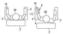
しかし上記従来の椅子式マッサージ機は、被施療者の両腕を固定した状態のままで背凭れ部を倒していく仕組みであり、したがって図12(b)に示すように被施療者50が腕の短い体型であるような場合にはストレッチ時点で上体が背凭れ部2から完全に浮いてしまって痛みを感じるという恐れがあった。
However, the conventional chair-type massage machine has a mechanism in which the backrest part is tilted while the arms of the user are fixed, and therefore the
また、両腕が固定されている状態では緊急時に脱出不能となる場合も考えられ、この点でも問題があった。
本発明は上記問題点に鑑みて発明したものであって、被施療者が腕の短い体型であってもストレッチ時点で上体が背凭れ部から完全に浮いて痛みを感じるといった恐れがなく、また緊急時にも容易に脱出可能となる椅子式マッサージ機を提供することを課題とするものである。 The present invention was invented in view of the above problems, and even if the user has a short body shape of the arm, there is no fear that the upper body completely floats from the backrest at the time of stretching and feels pain, It is another object of the present invention to provide a chair type massage machine that can be easily escaped in an emergency.
上記課題を解決するために本発明を、被施療者50が着座する座部1と、被施療者50の背中を凭れ掛ける背凭れ部2と、被施療者50の左右の腕を座部1側にそれぞれ挟持固定させる左右一対の腕固定部16と、座部1に対して背凭れ部2を起倒動作させる起倒動作部5と、左右一対の腕固定部16及び起倒動作部5を駆動制御する制御部14とを具備する椅子式マッサージ機において、上記制御部14を、左右一対のうち一方の腕固定部16で被施療者50の片腕を挟持固定させた状態で起倒動作部5により背凭れ部2を倒してストレッチ動作を行わせた後、背凭れ部2を一旦起こしたうえで、左右一対のうち他方の腕固定部16により被施療者50の他方の片腕を挟持固定させた状態で背凭れ部2を倒してストレッチ動作を行わせるものとし、且つ、上記腕固定部16の側方に自由空間を設けることにより、引っ張られる側の肩が背凭れ部2から浮き、もう一方の肩が背凭れ部2に凭れ掛かった体勢となり、腕固定部16に固定されて内側に振られた腕を上記自由空間に逃がしながら、自重により片側ずつ肩と腕にストレッチを施すことができるように設けたものとする。
In order to solve the above-mentioned problems, the present invention is made up of a
上記構成の椅子式マッサージ機とすることで、被施療者50が腕の短い体型であるような場合には、腕が固定される側の肩が背凭れ部2から浮いてしまっても被施療者50は自然と上体を捻った体勢をとって他方の肩を背凭れ部2に凭れ掛けさせることが可能である。つまり腕の長短等の体型に拠らず被施療者50はストレッチ動作中も背凭れ部2に凭れ掛かることができるので、強く引っ張られすぎて痛みを感じるといった事態が防止されるものである。加えて、固定されるのは片腕だけなので、緊急時等にも被施療者50は容易に脱出可能である。
By using the chair type massage machine having the above-described configuration, when the
また上記構成の椅子式マッサージ機にあっては、上記腕固定部16が、被施療者50の腕を上下方向から挟持固定するものであることが好適である。このようにすることで、腕固定部16により固定される腕の側方には自由な空間を形成することができる。したがって腕固定部16に固定されて引っ張られる腕が内側に振られた場合であっても、この腕固定部16に腕が押し当てられて被施療者50が痛みを感じるといった事態が防止されるものである。
Moreover, in the chair type massage machine of the said structure, it is suitable for the said arm fixing | fixed
また上記制御部14が、背凭れ部2が所定の基準角度よりも傾倒している場合には、起倒動作部5により背凭れ部2を上記基準角度にまで一旦起こしたうえで、腕固定部16により片腕を挟持固定させるものであることも好適である。このようにすることで、被施療者50の腕を腕固定部16の深い位置で毎度固定させ、充分なマッサージ感を与えることができるものである。
Further, when the
本発明は、左右一対のうち一方の腕固定部で被施療者の片腕を挟持固定させた状態で起倒動作部により背凭れ部を倒してストレッチ動作を行わせた後、背凭れ部を一旦起こしたうえで、左右一対の他方の腕固定部により被施療者の他方の片腕を挟持固定させた状態で背凭れ部を倒してストレッチ動作を行わせるものであることから、被施療者が腕の短い体型であってもストレッチ時点で上体が背凭れ部から完全に浮いて痛みを感じるといった恐れがなく、また緊急時にも容易に脱出可能であるといった効果を奏する。 In the present invention, one arm of the left and right pair is clamped and fixed with one arm of the user, and the backrest portion is tilted by the upright operation portion to perform the stretching operation, and then the backrest portion is temporarily removed. Because the arm rests on the backrest while the other arm of the user is sandwiched and fixed by the pair of left and right arm fixing parts and the stretching operation is performed. Even with a short body shape, there is no fear that the upper body is completely lifted from the backrest at the time of stretching, and there is an effect that it can be easily escaped in an emergency.
以下、本発明を添付図面に示す実施形態に基づいて説明する。図1は本発明の実施形態における一例の椅子式マッサージ機に被施療者50が着座している状態の側面図であり、図2は椅子式マッサージ機の正面図である。
Hereinafter, the present invention will be described based on embodiments shown in the accompanying drawings. FIG. 1 is a side view of a state in which a
本例の椅子式マッサージ機は、被施療者50が着座する座部1と、座部1に着座状態にある被施療者50が自身の背中を凭れ掛ける背凭れ部2と、同じく座部1に着座状態にある被施療者50が左右両腕をそれぞれ置いておくために座部1側に一体に取付けてある左右一対の肘掛部3とを具備するものである。以下の文中においては、被施療者50が背中を凭れ掛ける方向を「後方」、その逆方向(即ち、被施療者50が正面を向く方向)を「前方」として述べる。
The chair type massage machine of this example includes a
背凭れ部2内には、被施療者50の背面側に施療子41を押し当てて揉みや叩き等の各種マッサージを行う施療機構40を備えている。また座部1と背凭れ部2との間には、座部1に対して背凭れ部2を前後方向に起倒動作させてリクライニング角度を変更させるリクライニング機構として、起倒モータ4により電動で角度変更を行うリンク機構から成る起倒動作部5を備えている。
In the
左右の肘掛部3の上面にはそれぞれ、肘掛部3上に置いた被施療者50の一方の腕を上方から覆う腕カバー6が備えてあり、肘掛部3と腕カバー6とで形成される腕施療部7内に片腕を挿入して位置させるようになっている。肘掛部3と腕カバー6とは、互いの前端部を前後方向に回動自在に連結させており、肘掛部3の上面に対して腕カバー6が閉じた位置と、肘掛部3の上面に対して腕カバー6が所定角度だけ開いた位置との間で開閉自在となっている。
On the upper surfaces of the left and
左右一対の腕施療部7にはそれぞれ、腕カバー6の下面に配設されて給排気により膨縮自在な上エアバッグ8と、肘掛部3の上面に配設されて給排気により膨縮自在な下エアバッグ9とが、対向箇所に備えてある。この上下エアバッグ8,9により、腕施療部7内に挿入された腕は上下方向から包み込まれるように弾力的に挟持され、適宜のエアマッサージが施されるものである。
The pair of left and right
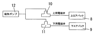
図3に示すように、上エアバッグ8と下エアバッグ9は、それぞれ専用の上用電磁弁10と下用電磁弁11を介して給気ポンプ12に連通接続されている。腕にエアマッサージを施す際には、給気ポンプ12を駆動させて給気を行うとともに各電磁弁10,11の開閉を選択することで、上エアバッグ8と下エアバッグ9のうち給気を行うものを選択して膨張させる。
As shown in FIG. 3, the
図4には制御構成図を示している。図示の如く、本例の椅子式マッサージ機には背凭れ部2の現在のリクライニング角度を検知する適宜の角度センサ13が備えてあり、この角度センサ13の検知結果が制御部14に入力されるようになっている。上記制御部14は、図5にも示す操作部15から入力される各種の指令に基づいて、左右の腕施療部7の上下エアバッグ8,9への給排気や、背凭れ部2の起倒動作を制御するものである。制御部14による給排気の制御は、左右それぞれの上下エアバッグ8,9に対応する上用電磁弁10及び下用電磁弁11と、給気ポンプ12とを、上記のように駆動制御することによって行う。
FIG. 4 shows a control configuration diagram. As shown in the figure, the chair type massage machine of this example is provided with an
また制御部14による背凭れ部2の起倒動作の制御は、角度センサ13により検知される現在のリクライニング角度から狙いのリクライニング角度にまで背凭れ部2が移動するように、起倒動作部5の起倒モータ4を駆動させることによって行う。
Further, the control of the
上記構成から成る本例の椅子式マッサージ機に着座した被施療者50は、操作部15に設けてある入/切ボタン20を操作して電源をオンにした後、リクライニング角度調整用のボタン(図示せず)を操作して背凭れ部2のリクライニング角度を所望角度に設定し、この状態で上述の施療機構40や腕施療部7による各種マッサージを施術させる。
The
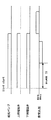
そして、操作部15に設けてある腕・肩伸ばしボタン17を押下して制御部14にストレッチ開始を指令すると、図6の動作タイミングチャートに示すような手順で腕や肩のストレッチ動作が行われる。本例にあっては左右の腕を片方ずつ引っ張ってストレッチするように設定してあるので、まず、右側又は左側の腕施療部7と対応する上用電磁弁10及び下用電磁弁11を開弁させるとともに給気ポンプ12を駆動させることで、右側又は左側の腕施療部7の上下エアバッグ8,9を同時に膨張させる。上記腕施療部7はこのストレッチ動作においては、被施療者50が肘掛部3上に置いた片腕の前腕部分を上下方向から包み込むように挟持固定する役割を果たすものである。したがって以下の文中にあっては、上記腕施療部7を、座部1側に被施療者50の片腕を挟持固定するための腕固定部16と称して説明する。
Then, when the arm / shoulder extension button 17 provided on the
上記制御部14は、上エアバッグ8と下エアバッグ9の膨張開始時点から一定の待ち時間T1が経過した時点から、腕を挟持固定させた状態を保ちながら起倒動作部5により背凭れ部2を後方へと一定速度で倒し始める。上記待ち時間T1は、上下エアバッグ8,9により腕が確実に固定されるまでの時間である。背凭れ部2が所定のリクライニング角度にまで倒れると、この位置で、制御部14は腕固定部16により片腕を挟持固定させた状態を保ちながら背凭れ部2を数秒間停止させる。このとき、背凭れ部2と共に上体を後方に倒すこととなる被施療者50には、自重によって肩や腕が引っ張られるストレッチが施されるものであり、特に片腕を固定しながら背凭れ部2を数秒間停止させることによって高いストレッチ効果が得られるようになっている。
The
上記ストレッチ終了後は、制御部14が上用電磁弁10及び下用電磁弁11を閉弁させるとともに給気ポンプ12を停止させ、上下エアバッグ8,9の排気を行うことで腕固定部16による腕の挟持固定を解除するとともに、この解除状態において背凭れ部2を所定のリクライニング角度にまで起こしていく。そして、次は他方の腕に対して同様の手順でストレッチ動作を行うものであり、このストレッチ動作を左右交互に何度か繰り返すよう設けることも好適である。
After the end of the stretch, the
なお、本例にあっては腕を挟持固定する際に上下エアバッグ8,9が同時に膨張するように設定してあるが、上エアバッグ8又は下エアバッグ9のみが膨張するように設定してあっても構わない。
In this example, the upper and
本例の椅子式マッサージ機にあっては上記の如く片腕ずつストレッチを施すよう設けてあることで、下記のような利点がある。 The chair type massage machine of the present example has the following advantages because it is provided to stretch one arm at a time as described above.
図7には被施療者50が腕の短い体型である場合を示している。図示のように本例にあっては片腕を肘掛部3上に固定して背凭れ部2を倒していく仕組みにしてあるので、背凭れ部2を大きく倒した状態で片方の肩(即ち引っ張られる側の肩)が背凭れ部2から浮いてしまっても、被施療者50は自然に上体を捻って他方の肩が背凭れ部2に凭れ掛かった体勢となる。勿論、被施療者50が腕の長い体型であれば、背凭れ部2を大きく倒した状態であっても両肩が背凭れ部2に凭れ掛かった体勢となる。ストレッチ時点で背凭れ部2から上体が完全に浮いた体勢[図12(b)参照]となれば被施療者50に痛みを与える恐れがあるのだが、本例にあっては上記の如く、被施療者50の腕の長短に関係なくこのような痛みを与えるといった事態が防止される。加えて、ストレッチ動作中であっても他方の腕は固定されていないので、緊急時にも自由な側の手で作業を行うことが可能である。また、ストレッチ動作中であっても自由な側の手で操作部15を操作して腕の固定を解除させれば、その場で両手を自由に使うことも、その場から即時に脱出することも可能である。
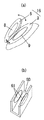
また本例にあっては既述の通り、被施療者50の腕を図8(a)に示すように上エアバッグ8と下エアバッグ9とで上下方向から挟持固定する仕組みになっているので、固定される腕の左右方向には自由な空間が形成される。したがって、ストレッチ動作中に図7の如く上体を捻る体勢となっても、これに伴って内側に振られた固定側の腕が腕固定部16に押し当てられて痛みを感じるといった事態が防止される。これに対して、例えば図8(b)の比較例にあるように上面の開口した溝部60内の左右両側面にエアバッグ61を配設し、該エアバッグ61により左右方向から腕を挟持固定する仕組みであれば、ストレッチ動作中に図7の如く上体を捻る体勢となれば、固定側の肘関節から先の部分が内側に振られて溝部60内の側面に押し当てられ、痛みを伴うような違和感を覚える恐れがある。つまり本例にあっては、腕が捻れて内側に振られる部分(図7中のA部参照)が側方の自由な空間に逃げるので、被施療者50に不快感を与えることがないものである。
FIG. 7 shows a case where the
In this example, as described above, the arm of the
次に、本発明の実施形態における他例の椅子式マッサージ機について図9〜図11に基づいて説明する。なお本例の基本的構成は上記した一例の構成と同様であることから、一例と同様の構成については同一符号を付して詳しい説明を省略し、一例とは相違する特徴的な構成についてのみ以下に詳述する。 Next, another chair type massage machine according to an embodiment of the present invention will be described with reference to FIGS. Since the basic configuration of this example is the same as the configuration of the above-described example, the same reference numerals are given to the same configuration as the example, and detailed description is omitted, and only the characteristic configuration that is different from the example is described. This will be described in detail below.
本例の椅子式マッサージ機においては背凭れ部2のリクライニング角度を、鉛直方向から後方に僅かに傾斜した角度から、後方に大きく傾斜した角度までの間で、8段階に等分割して設定してある(図9参照)。制御部14には角度センサ13により背凭れ部2の現在のリクライニング角度が入力されるものであり、ストレッチ動作を開始する時点ではまず、制御部14にて現在のリクライニング角度と所定の基準角度とを対比し、背凭れ部2が基準角度よりも後方に傾倒していると判定される場合には、背凭れ部2を起倒動作部5により基準角度にまで一旦起こしたうえで、腕固定部16により腕を挟持固定させるように設けている。この背凭れ部2を一旦起こす動作が予備動作であり、図11に示すように予備動作を終了すれば直ちに、一例にて既述したストレッチ動作を開始するよう設定してある。
In the chair type massage machine of this example, the reclining angle of the
上記予備動作を実行させる理由は、被施療者50が自身の腕を腕固定部16内にどの程度深く挿入して固定させるかでストレッチの強度が大きく相違するからである。図10(a)には被施療者50が腕を深く挿入して固定した場合を示しており、図10(b)には腕を浅く挿入して固定した場合を示している。図の対比から明らかなように、背凭れ部2を同程度だけ倒す場合に、図10(b)のように腕を浅い位置で固定した場合には図10(a)のように腕を深い位置で固定した場合と比べて被施療者50に充分なストレッチ感を与えることが困難になる。
The reason for executing the preliminary operation is that the strength of the stretch greatly differs depending on how deeply the
そこで本例にあってはストレッチ動作を開始する前に、被施療者50の腕を腕固定部16の奥にまで挿入させる上記予備動作を実行するように制御部14を設けてある。予備動作に用いる上記基準角度としては、鉛直方向から後方に向けて30°以内のクライニング角度αを設定することが好適であり、本例にあっては図9に示す2段階目のリクライニング角度を基準角度として制御部14に記憶させてある。
Therefore, in this example, before starting the stretching operation, the
上記構成から成る椅子式マッサージ機に着座した被施療者50が、操作部15に設けてある腕・肩伸ばしボタン17を押下して制御部14にストレッチ開始を指令すると、まず制御部14にて現在のリクライニング角度と基準角度とを対比し、背凭れ部2が基準角度よりも後方に傾倒していると判定される場合には、背凭れ部2を基準角度にまで一旦起こしたうえで、右側又は左側の腕固定部16に対応する上用電磁弁10及び下用電磁弁11を開弁させるとともに給気ポンプ12を駆動させることで、右側又は左側の腕施療部7の上下エアバッグ8,9を同時に膨張させる。上下エアバッグ8,9の膨張開始時点から一定の待ち時間T1が経過すると、片腕を固定した状態を保ちながら背凭れ部2を後方へと一定速度で倒し始め、背凭れ部2が所定のリクライニング角度にまで倒れると、この位置で片腕を固定させた状態を保ちながら背凭れ部2を数秒間停止させる。これにより、被施療者50は充分なマッサージ感を得ることができるものである。
When the
1 座部
2 背凭れ部
5 起倒動作部
14 制御部
16 腕固定部
50 被施療者
DESCRIPTION OF
Claims (3)
When the backrest part is tilted from a predetermined reference angle, the control part raises the backrest part to the reference angle by the raising / lowering operation part, and then holds one arm by the arm fixing part. The chair type massage machine according to claim 1 or 2, wherein the chair type massage machine is fixed.
Priority Applications (6)
| Application Number | Priority Date | Filing Date | Title |
|---|---|---|---|
| JP2006147390A JP4715636B2 (en) | 2006-05-26 | 2006-05-26 | Chair massage machine |
| US11/802,665 US7708340B2 (en) | 2006-05-26 | 2007-05-24 | Massage chair |
| KR1020070051011A KR100860352B1 (en) | 2006-05-26 | 2007-05-25 | A massage chair |
| CNU200720146328XU CN201076593Y (en) | 2006-05-26 | 2007-05-25 | Massage chair |
| CN2007101045457A CN101077327B (en) | 2006-05-26 | 2007-05-25 | Massage chair |
| HK08102607.3A HK1111591A1 (en) | 2006-05-26 | 2008-03-06 | A massage chair |
Applications Claiming Priority (1)
| Application Number | Priority Date | Filing Date | Title |
|---|---|---|---|
| JP2006147390A JP4715636B2 (en) | 2006-05-26 | 2006-05-26 | Chair massage machine |
Publications (2)
| Publication Number | Publication Date |
|---|---|
| JP2007313128A JP2007313128A (en) | 2007-12-06 |
| JP4715636B2 true JP4715636B2 (en) | 2011-07-06 |
Family
ID=38748833
Family Applications (1)
| Application Number | Title | Priority Date | Filing Date |
|---|---|---|---|
| JP2006147390A Expired - Fee Related JP4715636B2 (en) | 2006-05-26 | 2006-05-26 | Chair massage machine |
Country Status (5)
| Country | Link |
|---|---|
| US (1) | US7708340B2 (en) |
| JP (1) | JP4715636B2 (en) |
| KR (1) | KR100860352B1 (en) |
| CN (2) | CN201076593Y (en) |
| HK (1) | HK1111591A1 (en) |
Families Citing this family (15)
| Publication number | Priority date | Publication date | Assignee | Title |
|---|---|---|---|---|
| JP4293204B2 (en) * | 2006-05-26 | 2009-07-08 | パナソニック電工株式会社 | Chair massage machine |
| JP4715636B2 (en) * | 2006-05-26 | 2011-07-06 | パナソニック電工株式会社 | Chair massage machine |
| JP4435215B2 (en) * | 2007-07-19 | 2010-03-17 | 三洋電機株式会社 | Chair type massage machine |
| US8690239B2 (en) * | 2011-02-18 | 2014-04-08 | Daito Electric Machine Industry Company Limited | Chair-type massage apparatus |
| JP5892836B2 (en) * | 2012-03-30 | 2016-03-23 | 大東電機工業株式会社 | Chair type massage machine |
| JP6013165B2 (en) * | 2012-12-11 | 2016-10-25 | 株式会社フジ医療器 | Massage chair |
| KR102135854B1 (en) * | 2013-10-02 | 2020-07-21 | 코웨이 주식회사 | Control method of massage chair comprising air massage device |
| JP2017042282A (en) * | 2015-08-25 | 2017-03-02 | 株式会社フジ医療器 | Air massage device |
| CN105266442B (en) * | 2015-11-06 | 2017-11-17 | 合肥学院 | A kind of computer chair with adjustable lumbar support |
| JP2018143369A (en) * | 2017-03-02 | 2018-09-20 | 株式会社フジ医療器 | Massage system |
| CN108524217A (en) * | 2018-04-27 | 2018-09-14 | 羊芳 | A kind of whole-position massage armchair |
| JP7189811B2 (en) * | 2019-03-08 | 2022-12-14 | 株式会社フジ医療器 | controller chair |
| JP7267125B2 (en) * | 2019-06-28 | 2023-05-01 | 株式会社フジ医療器 | chair massage machine |
| CN112826271B (en) * | 2019-11-25 | 2023-02-03 | 魏宏帆 | Seat device and support device |
| CN111150624B (en) * | 2020-01-22 | 2021-11-05 | 铜川市人民医院 | Novel department of neurology cerebral apoplexy safety protection type rehabilitation training device |
Citations (8)
| Publication number | Priority date | Publication date | Assignee | Title |
|---|---|---|---|---|
| JP2003310683A (en) * | 2002-04-19 | 2003-11-05 | Family Kk | Massage machine |
| JP2005013463A (en) * | 2003-06-26 | 2005-01-20 | Fuji Iryoki:Kk | Massage machine |
| JP2005152260A (en) * | 2003-11-25 | 2005-06-16 | Matsushita Electric Works Ltd | Massage machine |
| JP2005160866A (en) * | 2003-12-04 | 2005-06-23 | Daito Denki Kogyo Kk | Chair type massage apparatus |
| JP2005177278A (en) * | 2003-12-22 | 2005-07-07 | Matsushita Electric Works Ltd | Chair type massage machine |
| JP2005278700A (en) * | 2004-03-26 | 2005-10-13 | Matsushita Electric Works Ltd | Chair type massage machine |
| JP2006087571A (en) * | 2004-09-22 | 2006-04-06 | Matsushita Electric Works Ltd | Massage machine |
| JP2006087830A (en) * | 2004-09-27 | 2006-04-06 | Matsushita Electric Works Ltd | Massage chair |
Family Cites Families (8)
| Publication number | Priority date | Publication date | Assignee | Title |
|---|---|---|---|---|
| CN1183263A (en) * | 1996-11-22 | 1998-06-03 | 富士医疗器股份有限公司 | Chair-type air massage device |
| AU2003261892A1 (en) * | 2002-09-09 | 2004-04-30 | Family Co., Ltd. | Massaging device and forearm massaging machine |
| JP4249558B2 (en) | 2003-07-09 | 2009-04-02 | ファミリー株式会社 | Chair type massage machine |
| TWI250871B (en) * | 2003-12-22 | 2006-03-11 | Matsushita Electric Works Ltd | Massage chair |
| JP2005218511A (en) | 2004-02-03 | 2005-08-18 | Daito Denki Kogyo Kk | Chair |
| JP4453564B2 (en) * | 2005-01-31 | 2010-04-21 | パナソニック電工株式会社 | Massage chair |
| JP4715636B2 (en) * | 2006-05-26 | 2011-07-06 | パナソニック電工株式会社 | Chair massage machine |
| JP4293204B2 (en) * | 2006-05-26 | 2009-07-08 | パナソニック電工株式会社 | Chair massage machine |
-
2006
- 2006-05-26 JP JP2006147390A patent/JP4715636B2/en not_active Expired - Fee Related
-
2007
- 2007-05-24 US US11/802,665 patent/US7708340B2/en active Active
- 2007-05-25 CN CNU200720146328XU patent/CN201076593Y/en not_active Expired - Lifetime
- 2007-05-25 CN CN2007101045457A patent/CN101077327B/en active Active
- 2007-05-25 KR KR1020070051011A patent/KR100860352B1/en not_active IP Right Cessation
-
2008
- 2008-03-06 HK HK08102607.3A patent/HK1111591A1/en not_active IP Right Cessation
Patent Citations (8)
| Publication number | Priority date | Publication date | Assignee | Title |
|---|---|---|---|---|
| JP2003310683A (en) * | 2002-04-19 | 2003-11-05 | Family Kk | Massage machine |
| JP2005013463A (en) * | 2003-06-26 | 2005-01-20 | Fuji Iryoki:Kk | Massage machine |
| JP2005152260A (en) * | 2003-11-25 | 2005-06-16 | Matsushita Electric Works Ltd | Massage machine |
| JP2005160866A (en) * | 2003-12-04 | 2005-06-23 | Daito Denki Kogyo Kk | Chair type massage apparatus |
| JP2005177278A (en) * | 2003-12-22 | 2005-07-07 | Matsushita Electric Works Ltd | Chair type massage machine |
| JP2005278700A (en) * | 2004-03-26 | 2005-10-13 | Matsushita Electric Works Ltd | Chair type massage machine |
| JP2006087571A (en) * | 2004-09-22 | 2006-04-06 | Matsushita Electric Works Ltd | Massage machine |
| JP2006087830A (en) * | 2004-09-27 | 2006-04-06 | Matsushita Electric Works Ltd | Massage chair |
Also Published As
| Publication number | Publication date |
|---|---|
| CN201076593Y (en) | 2008-06-25 |
| HK1111591A1 (en) | 2008-08-15 |
| JP2007313128A (en) | 2007-12-06 |
| CN101077327A (en) | 2007-11-28 |
| US7708340B2 (en) | 2010-05-04 |
| KR20070114049A (en) | 2007-11-29 |
| US20070273180A1 (en) | 2007-11-29 |
| CN101077327B (en) | 2011-05-18 |
| KR100860352B1 (en) | 2008-09-25 |
Similar Documents
| Publication | Publication Date | Title |
|---|---|---|
| JP4715636B2 (en) | Chair massage machine | |
| JP4293204B2 (en) | Chair massage machine | |
| US8083700B2 (en) | Chair type massager | |
| JP4651556B2 (en) | Massage machine | |
| JP5078115B2 (en) | Chair massage machine | |
| JP2009034242A (en) | Massage machine | |
| JP4615922B2 (en) | Massage machine | |
| JP5036249B2 (en) | Treatment machine | |
| JP2005152260A (en) | Massage machine | |
| JP4684151B2 (en) | Massage machine | |
| JP2007289445A (en) | Massage machine | |
| JP2007313129A (en) | Chair-type massage machine | |
| WO2016199461A1 (en) | Massage machine | |
| JP2008049087A (en) | Massaging machine | |
| JP2000167003A (en) | Chair | |
| JP4121921B2 (en) | Chair massage machine | |
| JP5086412B2 (en) | Massage machine | |
| JP4550498B2 (en) | Massage machine | |
| JP2005058660A (en) | Massage machine | |
| JP7070889B2 (en) | Massage machine | |
| JP2010214155A (en) | Massage machine | |
| JP2006087830A (en) | Massage chair | |
| JP2020000616A (en) | Chair | |
| JP2020092726A (en) | Massage machine | |
| WO2010150646A1 (en) | Relaxation device |
Legal Events
| Date | Code | Title | Description |
|---|---|---|---|
| A621 | Written request for application examination |
Free format text: JAPANESE INTERMEDIATE CODE: A621 Effective date: 20080616 |
|
| A977 | Report on retrieval |
Free format text: JAPANESE INTERMEDIATE CODE: A971007 Effective date: 20100610 |
|
| A131 | Notification of reasons for refusal |
Free format text: JAPANESE INTERMEDIATE CODE: A131 Effective date: 20100615 |
|
| A521 | Request for written amendment filed |
Free format text: JAPANESE INTERMEDIATE CODE: A523 Effective date: 20100816 |
|
| RD04 | Notification of resignation of power of attorney |
Free format text: JAPANESE INTERMEDIATE CODE: A7424 Effective date: 20100816 |
|
| A131 | Notification of reasons for refusal |
Free format text: JAPANESE INTERMEDIATE CODE: A131 Effective date: 20101207 |
|
| A521 | Request for written amendment filed |
Free format text: JAPANESE INTERMEDIATE CODE: A523 Effective date: 20110207 |
|
| TRDD | Decision of grant or rejection written | ||
| A01 | Written decision to grant a patent or to grant a registration (utility model) |
Free format text: JAPANESE INTERMEDIATE CODE: A01 Effective date: 20110301 |
|
| A61 | First payment of annual fees (during grant procedure) |
Free format text: JAPANESE INTERMEDIATE CODE: A61 Effective date: 20110314 |
|
| R151 | Written notification of patent or utility model registration |
Ref document number: 4715636 Country of ref document: JP Free format text: JAPANESE INTERMEDIATE CODE: R151 |
|
| FPAY | Renewal fee payment (event date is renewal date of database) |
Free format text: PAYMENT UNTIL: 20140408 Year of fee payment: 3 |
|
| LAPS | Cancellation because of no payment of annual fees |