JP4715403B2 - Micro chemical reactor - Google Patents
Micro chemical reactor Download PDFInfo
- Publication number
- JP4715403B2 JP4715403B2 JP2005260032A JP2005260032A JP4715403B2 JP 4715403 B2 JP4715403 B2 JP 4715403B2 JP 2005260032 A JP2005260032 A JP 2005260032A JP 2005260032 A JP2005260032 A JP 2005260032A JP 4715403 B2 JP4715403 B2 JP 4715403B2
- Authority
- JP
- Japan
- Prior art keywords
- solution
- flow channel
- substrate
- flow
- flow path
- Prior art date
- Legal status (The legal status is an assumption and is not a legal conclusion. Google has not performed a legal analysis and makes no representation as to the accuracy of the status listed.)
- Active
Links
- 239000000758 substrate Substances 0.000 claims description 128
- 238000006243 chemical reaction Methods 0.000 claims description 63
- 230000002093 peripheral effect Effects 0.000 claims description 19
- 238000005192 partition Methods 0.000 claims description 12
- 230000000149 penetrating effect Effects 0.000 claims description 9
- 239000000243 solution Substances 0.000 description 168
- 239000007788 liquid Substances 0.000 description 19
- XLYOFNOQVPJJNP-UHFFFAOYSA-N water Substances O XLYOFNOQVPJJNP-UHFFFAOYSA-N 0.000 description 13
- 239000000203 mixture Substances 0.000 description 5
- 238000009792 diffusion process Methods 0.000 description 4
- 230000035484 reaction time Effects 0.000 description 4
- 238000010438 heat treatment Methods 0.000 description 3
- 239000011521 glass Substances 0.000 description 2
- 238000000034 method Methods 0.000 description 2
- 239000011259 mixed solution Substances 0.000 description 2
- 238000007789 sealing Methods 0.000 description 2
- 230000008602 contraction Effects 0.000 description 1
- 238000001816 cooling Methods 0.000 description 1
- 238000010586 diagram Methods 0.000 description 1
- 238000005530 etching Methods 0.000 description 1
- 238000002474 experimental method Methods 0.000 description 1
- 239000000463 material Substances 0.000 description 1
- 239000002184 metal Substances 0.000 description 1
- 230000010349 pulsation Effects 0.000 description 1
- 238000010008 shearing Methods 0.000 description 1
- 229910001220 stainless steel Inorganic materials 0.000 description 1
- 239000010935 stainless steel Substances 0.000 description 1
- 238000011144 upstream manufacturing Methods 0.000 description 1
Images


Classifications
-
- B—PERFORMING OPERATIONS; TRANSPORTING
- B01—PHYSICAL OR CHEMICAL PROCESSES OR APPARATUS IN GENERAL
- B01J—CHEMICAL OR PHYSICAL PROCESSES, e.g. CATALYSIS OR COLLOID CHEMISTRY; THEIR RELEVANT APPARATUS
- B01J19/00—Chemical, physical or physico-chemical processes in general; Their relevant apparatus
- B01J19/0093—Microreactors, e.g. miniaturised or microfabricated reactors
-
- B—PERFORMING OPERATIONS; TRANSPORTING
- B01—PHYSICAL OR CHEMICAL PROCESSES OR APPARATUS IN GENERAL
- B01F—MIXING, e.g. DISSOLVING, EMULSIFYING OR DISPERSING
- B01F33/00—Other mixers; Mixing plants; Combinations of mixers
- B01F33/30—Micromixers
- B01F33/301—Micromixers using specific means for arranging the streams to be mixed, e.g. channel geometries or dispositions
- B01F33/3011—Micromixers using specific means for arranging the streams to be mixed, e.g. channel geometries or dispositions using a sheathing stream of a fluid surrounding a central stream of a different fluid, e.g. for reducing the cross-section of the central stream or to produce droplets from the central stream
-
- B—PERFORMING OPERATIONS; TRANSPORTING
- B01—PHYSICAL OR CHEMICAL PROCESSES OR APPARATUS IN GENERAL
- B01F—MIXING, e.g. DISSOLVING, EMULSIFYING OR DISPERSING
- B01F33/00—Other mixers; Mixing plants; Combinations of mixers
- B01F33/30—Micromixers
- B01F33/301—Micromixers using specific means for arranging the streams to be mixed, e.g. channel geometries or dispositions
- B01F33/3012—Interdigital streams, e.g. lamellae
-
- B—PERFORMING OPERATIONS; TRANSPORTING
- B01—PHYSICAL OR CHEMICAL PROCESSES OR APPARATUS IN GENERAL
- B01J—CHEMICAL OR PHYSICAL PROCESSES, e.g. CATALYSIS OR COLLOID CHEMISTRY; THEIR RELEVANT APPARATUS
- B01J2219/00—Chemical, physical or physico-chemical processes in general; Their relevant apparatus
- B01J2219/00781—Aspects relating to microreactors
- B01J2219/00783—Laminate assemblies, i.e. the reactor comprising a stack of plates
-
- B—PERFORMING OPERATIONS; TRANSPORTING
- B01—PHYSICAL OR CHEMICAL PROCESSES OR APPARATUS IN GENERAL
- B01J—CHEMICAL OR PHYSICAL PROCESSES, e.g. CATALYSIS OR COLLOID CHEMISTRY; THEIR RELEVANT APPARATUS
- B01J2219/00—Chemical, physical or physico-chemical processes in general; Their relevant apparatus
- B01J2219/00781—Aspects relating to microreactors
- B01J2219/00819—Materials of construction
- B01J2219/00822—Metal
-
- B—PERFORMING OPERATIONS; TRANSPORTING
- B01—PHYSICAL OR CHEMICAL PROCESSES OR APPARATUS IN GENERAL
- B01J—CHEMICAL OR PHYSICAL PROCESSES, e.g. CATALYSIS OR COLLOID CHEMISTRY; THEIR RELEVANT APPARATUS
- B01J2219/00—Chemical, physical or physico-chemical processes in general; Their relevant apparatus
- B01J2219/00781—Aspects relating to microreactors
- B01J2219/00819—Materials of construction
- B01J2219/00831—Glass
-
- B—PERFORMING OPERATIONS; TRANSPORTING
- B01—PHYSICAL OR CHEMICAL PROCESSES OR APPARATUS IN GENERAL
- B01J—CHEMICAL OR PHYSICAL PROCESSES, e.g. CATALYSIS OR COLLOID CHEMISTRY; THEIR RELEVANT APPARATUS
- B01J2219/00—Chemical, physical or physico-chemical processes in general; Their relevant apparatus
- B01J2219/00781—Aspects relating to microreactors
- B01J2219/00851—Additional features
- B01J2219/00858—Aspects relating to the size of the reactor
- B01J2219/0086—Dimensions of the flow channels
-
- B—PERFORMING OPERATIONS; TRANSPORTING
- B01—PHYSICAL OR CHEMICAL PROCESSES OR APPARATUS IN GENERAL
- B01J—CHEMICAL OR PHYSICAL PROCESSES, e.g. CATALYSIS OR COLLOID CHEMISTRY; THEIR RELEVANT APPARATUS
- B01J2219/00—Chemical, physical or physico-chemical processes in general; Their relevant apparatus
- B01J2219/00781—Aspects relating to microreactors
- B01J2219/00851—Additional features
- B01J2219/00858—Aspects relating to the size of the reactor
- B01J2219/00862—Dimensions of the reaction cavity itself
-
- B—PERFORMING OPERATIONS; TRANSPORTING
- B01—PHYSICAL OR CHEMICAL PROCESSES OR APPARATUS IN GENERAL
- B01J—CHEMICAL OR PHYSICAL PROCESSES, e.g. CATALYSIS OR COLLOID CHEMISTRY; THEIR RELEVANT APPARATUS
- B01J2219/00—Chemical, physical or physico-chemical processes in general; Their relevant apparatus
- B01J2219/00781—Aspects relating to microreactors
- B01J2219/00889—Mixing
-
- B—PERFORMING OPERATIONS; TRANSPORTING
- B01—PHYSICAL OR CHEMICAL PROCESSES OR APPARATUS IN GENERAL
- B01J—CHEMICAL OR PHYSICAL PROCESSES, e.g. CATALYSIS OR COLLOID CHEMISTRY; THEIR RELEVANT APPARATUS
- B01J2219/00—Chemical, physical or physico-chemical processes in general; Their relevant apparatus
- B01J2219/00781—Aspects relating to microreactors
- B01J2219/00891—Feeding or evacuation
Landscapes
- Chemical & Material Sciences (AREA)
- Chemical Kinetics & Catalysis (AREA)
- Organic Chemistry (AREA)
- Physical Or Chemical Processes And Apparatus (AREA)
- Micromachines (AREA)
Description
本発明は、化学反応装置に係り、特に異なる2液を混合または反応させる微小流路が形成されるマイクロリアクタを用いた化学反応装置に関する。 The present invention relates to a chemical reaction apparatus, and more particularly to a chemical reaction apparatus using a microreactor in which a micro flow path for mixing or reacting two different liquids is formed.
従来のマイクロリアクタを有する化学反応装置の例が、特許文献1に記載されている。この公報に記載の化学反応装置に用いるマイクロリアクタは、基本的なY字型やT字型のマイクロリアクタを改良したものであり、多層構造のマイクロリアクタである。すなわち、第1の溶液用、ついで第2の溶液用、また第1の溶液用、第2の溶液用…というように、平板上に第1、第2の溶液が交互に流れるように、複数の流路を空間配置している。 An example of a chemical reaction apparatus having a conventional microreactor is described in Patent Document 1. The microreactor used in the chemical reaction apparatus described in this publication is an improvement of the basic Y-shaped or T-shaped microreactor, and is a multi-layered microreactor. That is, for the first solution, the second solution, the first solution, the second solution,... The flow paths are arranged in space.
基本的なY字型やT字型のマイクロリアクタは、最も簡単な形状のマイクロリアクタであり、第1の溶液と第2の溶液とは分子拡散で混合して、反応が生じる。混合の時間は、マイクロリアクタの流路幅の2乗に比例し、流路幅が小さければ反応が効率的に進む。この基本的なマイクロリアクタの改良版である特許文献1に記載のマイクロリアクタでは、多層構造にしているので、反応流量を増大できる。 A basic Y-shaped or T-shaped microreactor is the microreactor having the simplest shape, and the first solution and the second solution are mixed by molecular diffusion to cause a reaction. The mixing time is proportional to the square of the channel width of the microreactor, and the reaction proceeds efficiently if the channel width is small. Since the microreactor described in Patent Document 1, which is an improved version of this basic microreactor, has a multilayer structure, the reaction flow rate can be increased.
マイクロロアクタの他の例が、非特許文献1に開示されている。この文献に記載のマイクロリアクタは、中心衝突型とでも呼ぶべきものであり、円板の半径方向に形成された複数の流路の外周部から中心部に向けて、第1、第2の溶液を流し、中心部で2液を衝突させている。衝突時のせん断力で、2液を効率よく混合させている。 Another example of the microactor is disclosed in Non-Patent Document 1. The microreactor described in this document should also be called a center collision type, and the first and second solutions are applied from the outer periphery of a plurality of flow paths formed in the radial direction of the disk toward the center. The two liquids collide with each other at the center. The two liquids are efficiently mixed by the shearing force at the time of collision.
従来のY字型やT字型のマイクロリアクタを用いた2液の化学反応装置では、反応効率を向上させるために、数10μm〜数100μm程度に形成されたマイクロ流路に溶液を流しているので、流せる流量を十分に確保することが困難であった。混合性能と圧力損失はトレードオフの関係にあり、混合性能を向上させるためにはマイクロ流路の代表径を小さくするのが好ましい。一方、マイクロ流路の代表径を小さくすると、圧力損失が代表径の4乗に反比例して大きくなり、流動抵抗が増大して流量を増大させることが困難である。 In a two-component chemical reaction apparatus using a conventional Y-shaped or T-shaped microreactor, the solution is caused to flow through a microchannel formed in the order of several tens to several hundreds of micrometers in order to improve the reaction efficiency. It was difficult to ensure a sufficient flow rate. The mixing performance and pressure loss are in a trade-off relationship, and it is preferable to reduce the representative diameter of the microchannel in order to improve the mixing performance. On the other hand, when the representative diameter of the microchannel is reduced, the pressure loss increases in inverse proportion to the fourth power of the representative diameter, and it is difficult to increase the flow resistance and increase the flow rate.
この不具合を解消するための上記特許文献1に記載の化学反応装置では、多層構造のマイクロリアクタを採用しているので、流せる流量を多くすることは可能であるが、流路チップの大きさが大きくなるという、新たな不具合を生じている。 In the chemical reaction apparatus described in Patent Document 1 for solving this problem, a multi-layer microreactor is employed, so that it is possible to increase the flow rate that can be flowed, but the size of the flow path chip is large. This is a new problem.
さらに、上記非特許文献1に記載の方法では、異なる2種の溶液の混合または反応を円板の中心部でしか行えず、マイクロリアクタの面積に比べて反応領域がわずかであり、反応流量を増大できない、という不具合を発生する。 Furthermore, in the method described in Non-Patent Document 1, two different types of solutions can be mixed or reacted only at the center of the disk, and the reaction area is small compared to the area of the microreactor, increasing the reaction flow rate. The problem that it is not possible occurs.
本発明は上記従来技術の不具合に鑑みなされたものであり、その目的は、マイクロリアクタを用いた2液の化学反応装置において、高効率で反応させるとともに反応溶液を増大させることにある。本発明の他の目的は、反応溶液を増大させながらマイクロリアクタを小型化することにある。 The present invention has been made in view of the above-mentioned problems of the prior art, and an object thereof is to increase the reaction solution while allowing the reaction to occur with high efficiency in a two-liquid chemical reaction apparatus using a microreactor. Another object of the present invention is to reduce the size of the microreactor while increasing the reaction solution.
上記目的を達成するための本発明の特徴は、所定の面側に所定の深さで半径方向に形成された複数個の流路溝を有する円盤状の流路溝基板と、前記複数個の前記流路溝を密封し中心部に流出孔が形成された流路蓋基板とを備え、第1及び第2の溶液を前記流路溝の外周側から中心部に向けて流し、前記中心部に設けられた中心合流部を介して前記流出孔から流出させるマイクロ化学反応装置であって、前記複数個の流路溝の各々は、前記流路溝基板の周方向に形成され、前記中心合流部で互いに連結され、流路の幅が前記流路基板の外周側から前記中心合流部に至るまで徐々に狭くなるように形成された扇形状の流路溝で構成された複数個の第1の溶液流路溝と、前記第1の溶液流路溝の外縁部から外方へ放射状かつ半径方向に形成された複数個の第2の溶液流路溝と、前記複数個の第1の溶液流路溝の各々の外縁部において、周方向に設けられ、前記流路溝基板の裏面側まで貫通し、前記第1の溶液が導入される第1の分岐流入孔と、前記複数個の第2の溶液流路溝の各々の外縁部に設けられ、前記流路溝基板の裏面側まで貫通し、前記第2の溶液が導入される第2の分岐流入孔とを備え、前記複数個の流路溝の各々の間に、円板状基板の中心の極一部を除いた位置まで延伸された仕切り壁が形成され、前記第1の分岐流入孔から導入された前記第1の溶液と前記第2の分岐流入孔から導入された前記第2の溶液とは、前記流路溝を外径側から内径側へ移動し、その途中において混合反応し、前記中心合流部を介して前記流出孔から流出するものであって、更に、中央部に凹部が形成された入口筐体部材と、前記入口筐体部材の上側に配置された前記凹部に凸部が嵌合する出口筐体部材とを備え、前記入口筐体部材の凹部には、下側から順に前記流路溝基板,前記流路蓋基板が収容され、前記第1の溶液及び第2の溶液は、前記入口筐体部材に設けられた入口部から導かれ、前記流出孔を経て前記出口筐体部材に形成された出口部から取り出されることにある。 In order to achieve the above object, the present invention is characterized in that a disk-shaped flow channel substrate having a plurality of flow channels formed in a radial direction at a predetermined depth on a predetermined surface side, and the plurality of the plurality of flow channels A flow path lid substrate in which the flow path groove is sealed and an outflow hole is formed in the center, and the first and second solutions are flowed from the outer peripheral side of the flow path toward the center, A microchemical reaction apparatus for flowing out from the outflow hole through a central merging portion provided in the central channel, wherein each of the plurality of flow channel grooves is formed in a circumferential direction of the flow channel groove substrate; Are connected to each other, and a plurality of first channels each composed of a fan-shaped channel groove formed such that the width of the channel gradually narrows from the outer peripheral side of the channel substrate to the central junction. And a plurality of solution channel grooves formed radially and radially outward from the outer edge of the first solution channel groove. A plurality of second solution flow channel grooves and outer edges of each of the plurality of first solution flow channel grooves, provided in a circumferential direction, penetrating to the back surface side of the flow channel substrate, and Provided at the outer edge of each of the plurality of second solution flow channel grooves, penetrating to the back surface side of the flow channel substrate, and A partition wall extending to a position excluding a part of the center of the disk-shaped substrate is formed between each of the plurality of flow channel grooves. The first solution introduced from the first branch inflow hole and the second solution introduced from the second branch inflow hole move the channel groove from the outer diameter side to the inner diameter side. It moves, mixes and reacts in the middle, and flows out of the outflow hole through the central merging portion. An inlet housing member formed, and an outlet housing member in which a convex portion fits into the concave portion disposed on the upper side of the inlet housing member. The flow path groove substrate and the flow path lid substrate are accommodated in order, and the first solution and the second solution are guided from an inlet portion provided in the inlet housing member, and pass through the outlet hole to the outlet. It exists in taking out from the exit part formed in the housing member .
上記目的を達成する本発明の他の特徴は、所定の面側に所定の深さで半径方向に形成された複数個の流路溝を有する円盤状の流路溝基板と、前記複数個の前記流路溝を密封し中心部に流出孔が形成された流路蓋基板とを備え、第1及び第2の溶液を前記流路溝の外周側から中心部に向けて流し、前記中心部に設けられた中心合流部を介して前記流出孔から流出させるマイクロ化学反応装置であって、前記複数個の流路溝の各々は、前記流路溝基板の周方向に形成され、前記中心合流部で互いに連結され、流路の幅が前記流路基板の外周側から前記中心合流部に至るまで徐々に狭くなるように形成された扇形状の流路溝で構成された複数個の第1の溶液流路溝と、前記第1の溶液流路溝の外縁部から外方へ放射状かつ半径方向に形成された複数個の第2の溶液流路溝と、前記複数個の第1の溶液流路溝の各々の外縁部において、周方向に設けられ、前記流路溝基板の裏面側まで貫通し、前記第1の溶液が導入される第1の分岐流入孔と、前記複数個の第2の溶液流路溝の各々の外縁部に設けられ、前記流路溝基板の裏面側まで貫通し、前記第2の溶液が導入される第2の分岐流入孔とを備え、前記複数個の流路溝の各々の間に、円板状基板の中心の極一部を除いた位置まで延伸された仕切り壁が形成され、前記第1の分岐流入孔から導入された前記第1の溶液と前記第2の分岐流入孔から導入された前記第2の溶液とは、前記流路溝を外径側から内径側へ移動し、その途中において混合反応し、前記中心合流部を介して前記流出孔から流出するものであって、更に、中央部に凹部が形成された入口筐体部材と、前記入口筐体部材の上側に配置された前記凹部に凸部が嵌合する出口筐体部材とを備え、前記入口筐体部材の凹部には、下側から順に前記流路溝基板,前記流路蓋基板が収容され、前記流路溝基板,前記流路蓋基板,前記入口筐体部材及び前記出口筐体部材は、接触面を鏡面上げされ、前記入口筐体部材と前記出口筐体部材とがボルトで締結されたことにある。Another feature of the present invention that achieves the above object is to provide a disk-shaped flow channel substrate having a plurality of flow channels formed in a radial direction at a predetermined depth on a predetermined surface side, and the plurality of the plurality of flow channels. A flow path lid substrate in which the flow path groove is sealed and an outflow hole is formed in the center, and the first and second solutions are flowed from the outer peripheral side of the flow path toward the center, A microchemical reaction apparatus for flowing out from the outflow hole through a central merging portion provided in the central channel, wherein each of the plurality of flow channel grooves is formed in a circumferential direction of the flow channel groove substrate; Are connected to each other, and a plurality of first channels each composed of a fan-shaped channel groove formed such that the width of the channel gradually narrows from the outer peripheral side of the channel substrate to the central junction. And a plurality of solution channel grooves formed radially and radially outward from the outer edge of the first solution channel groove Each of the second solution flow channel grooves and the outer edges of the plurality of first solution flow channel grooves are provided in the circumferential direction, penetrate to the back surface side of the flow channel groove substrate, and A first branch inflow hole into which the solution is introduced and an outer edge portion of each of the plurality of second solution flow channel grooves, penetrating to the back surface side of the flow channel substrate, and the second solution A partition wall extending to a position excluding a part of the center of the disk-shaped substrate is formed between each of the plurality of flow channel grooves. The first solution introduced from the first branch inflow hole and the second solution introduced from the second branch inflow hole move the flow channel from the outer diameter side to the inner diameter side. In the middle of the mixing reaction, the mixture flows out from the outflow hole through the central merging portion, and a recess is formed in the central portion. An inlet housing member and an outlet housing member in which a convex portion fits into the concave portion disposed on the upper side of the inlet housing member, and the concave portion of the inlet housing member in order from the lower side. The channel groove substrate and the channel lid substrate are accommodated, and the channel groove substrate, the channel lid substrate, the inlet housing member, and the outlet housing member are mirror-raised on the contact surface, and the inlet housing The body member and the outlet housing member are fastened with bolts.
上記目的を達成する本発明の他の特徴は、所定の面側に所定の深さで半径方向に形成された複数個の流路溝を有する円盤状の流路溝基板と、前記複数個の前記流路溝を密封し中心部に流出孔が形成された流路蓋基板とを備え、第1及び第2の溶液を前記流路溝の外周側から中心部に向けて流し、前記中心部に設けられた中心合流部を介して前記流出孔から流出させるマイクロ化学反応装置であって、前記複数個の流路溝の各々は、前記流路溝基板の周方向に形成され、前記中心合流部で互いに連結され、流路の幅が前記流路基板の外周側から前記中心合流部に至るまで徐々に狭くなるように形成された扇形状の流路溝で構成された複数個の第1の溶液流路溝と、前記第1の溶液流路溝の外縁部から外方へ放射状かつ半径方向に形成された複数個の第2の溶液流路溝と、前記複数個の第1の溶液流路溝の各々の外縁部において、周方向に設けられ、前記流路溝基板の裏面側まで貫通し、前記第1の溶液が導入される第1の分岐流入孔と、前記複数個の第2の溶液流路溝の各々の外縁部に設けられ、前記流路溝基板の裏面側まで貫通し、前記第2の溶液が導入される第2の分岐流入孔とを備え、前記複数個の流路溝の各々の間に、円板状基板の中心の極一部を除いた位置まで延伸された仕切り壁が形成され、前記第1の分岐流入孔から導入された前記第1の溶液と前記第2の分岐流入孔から導入された前記第2の溶液とは、前記流路溝を外径側から内径側へ移動し、その途中において混合反応し、前記中心合流部を介して前記流出孔から流出するものであって、更に、中央部に凹部が形成された入口筐体部材と、前記入口筐体部材の上側に配置された前記凹部に凸部が嵌合する出口筐体部材とを備え、前記入口筐体部材の凹部には、下側から順に前記流路溝基板,前記流路蓋基板が収容され、前記流路溝基板及び前記流路蓋基板は円板の対向する2面に切り欠き部が形成され、前記凹部は対向する2辺を切り欠いた円柱形状とされたことにある。Another feature of the present invention that achieves the above object is to provide a disk-shaped flow channel substrate having a plurality of flow channels formed in a radial direction at a predetermined depth on a predetermined surface side, and the plurality of the plurality of flow channels. A flow path lid substrate in which the flow path groove is sealed and an outflow hole is formed in the center, and the first and second solutions are flowed from the outer peripheral side of the flow path toward the center, A microchemical reaction apparatus for flowing out from the outflow hole through a central merging portion provided in the central channel, wherein each of the plurality of flow channel grooves is formed in a circumferential direction of the flow channel groove substrate; Are connected to each other, and a plurality of first channels each composed of a fan-shaped channel groove formed such that the width of the channel gradually narrows from the outer peripheral side of the channel substrate to the central junction. And a plurality of solution channel grooves formed radially and radially outward from the outer edge of the first solution channel groove Each of the second solution flow channel grooves and the outer edges of the plurality of first solution flow channel grooves are provided in the circumferential direction, penetrate to the back surface side of the flow channel groove substrate, and A first branch inflow hole into which the solution is introduced and an outer edge portion of each of the plurality of second solution flow channel grooves, penetrating to the back surface side of the flow channel substrate, and the second solution A partition wall extending to a position excluding a part of the center of the disk-shaped substrate is formed between each of the plurality of flow channel grooves. The first solution introduced from the first branch inflow hole and the second solution introduced from the second branch inflow hole move the flow channel from the outer diameter side to the inner diameter side. In the middle of the mixing reaction, the mixture flows out from the outflow hole through the central merging portion, and a recess is formed in the central portion. An inlet housing member and an outlet housing member in which a convex portion fits into the concave portion disposed on the upper side of the inlet housing member, and the concave portion of the inlet housing member in order from the lower side. The channel groove substrate and the channel lid substrate are accommodated, the channel groove substrate and the channel lid substrate have notches formed on two opposing surfaces of the disk, and the recess has two opposing sides. It is in the shape of a cutout cylinder.
上記目的を達成する本発明の他の特徴は、所定の面側に所定の深さで半径方向に形成された複数個の流路溝を有する円盤状の流路溝基板と、前記複数個の前記流路溝を密封し中心部に流出孔が形成された流路蓋基板とを備え、第1及び第2の溶液を前記流路溝の外周側から中心部に向けて流し、前記中心部に設けられた中心合流部を介して前記流出孔から流出させるマイクロ化学反応装置であって、前記複数個の流路溝の各々は、前記流路溝基板の周方向に形成され、前記中心合流部で互いに連結され、流路の幅が前記流路基板の外周側から前記中心合流部に至るまで徐々に狭くなるように形成された扇形状の流路溝で構成された複数個の第1の溶液流路溝と、前記第1の溶液流路溝の外縁部から外方へ放射状かつ半径方向に形成された複数個の第2の溶液流路溝と、前記複数個の第1の溶液流路溝の各々の外縁部において、周方向に設けられ、前記流路溝基板の裏面側まで貫通し、前記第1の溶液が導入される第1の分岐流入孔と、前記複数個の第2の溶液流路溝の各々の外縁部に設けられ、前記流路溝基板の裏面側まで貫通し、前記第2の溶液が導入される第2の分岐流入孔とを備え、前記複数個の流路溝の各々の間に、円板状基板の中心の極一部を除いた位置まで延伸された仕切り壁が形成され、前記第1の分岐流入孔から導入された前記第1の溶液と前記第2の分岐流入孔から導入された前記第2の溶液とは、前記流路溝を外径側から内径側へ移動し、その途中において混合反応し、前記中心合流部を介して前記流出孔から流出するものであって、更に、中央部に凹部が形成された入口筐体部材と、前記入口筐体部材の上側に配置された前記凹部に凸部が嵌合する出口筐体部材とを備え、前記入口筐体部材の凹部には、下側から順に前記流路溝基板,前記流路蓋基板が収容され、前記凹部上面の前記扇形状溝に対応し、外径が前記第1の分岐流入孔よりも外径側で前記の第2の分岐流入孔よりも内径側の位置に配置された第1の溶液用プール部と、前記第1の溶液用プール部間に形成された扇状の支持土手と、前記第1の溶液用プール部の外周側にリング状として形成され、内径位置が前記第1の分岐流入孔よりも外径側で、外径位置が前記第2の分岐流入孔よりも外径側とされた第2の溶液用プール部とを備えたことにある。Another feature of the present invention that achieves the above object is to provide a disk-shaped flow channel substrate having a plurality of flow channels formed in a radial direction at a predetermined depth on a predetermined surface side, and the plurality of the plurality of flow channels. A flow path lid substrate in which the flow path groove is sealed and an outflow hole is formed in the center, and the first and second solutions are flowed from the outer peripheral side of the flow path toward the center, A microchemical reaction apparatus for flowing out from the outflow hole through a central merging portion provided in the central channel, wherein each of the plurality of flow channel grooves is formed in a circumferential direction of the flow channel groove substrate; Are connected to each other, and a plurality of first channels each composed of a fan-shaped channel groove formed such that the width of the channel gradually narrows from the outer peripheral side of the channel substrate to the central junction. And a plurality of solution channel grooves formed radially and radially outward from the outer edge of the first solution channel groove Each of the second solution flow channel grooves and the outer edges of the plurality of first solution flow channel grooves are provided in the circumferential direction, penetrate to the back surface side of the flow channel groove substrate, and A first branch inflow hole into which the solution is introduced and an outer edge portion of each of the plurality of second solution flow channel grooves, penetrating to the back surface side of the flow channel substrate, and the second solution A partition wall extending to a position excluding a part of the center of the disk-shaped substrate is formed between each of the plurality of flow channel grooves. The first solution introduced from the first branch inflow hole and the second solution introduced from the second branch inflow hole move the flow channel from the outer diameter side to the inner diameter side. In the middle of the mixing reaction, the mixture flows out from the outflow hole through the central merging portion, and a recess is formed in the central portion. An inlet housing member and an outlet housing member in which a convex portion fits into the concave portion disposed on the upper side of the inlet housing member, and the concave portion of the inlet housing member in order from the lower side. The flow path groove substrate and the flow path cover substrate are accommodated and correspond to the fan-shaped groove on the upper surface of the recess, and the outer diameter is the second branch inflow on the outer diameter side of the first branch inflow hole. A first solution pool portion disposed at a position on the inner diameter side of the hole; a fan-shaped support bank formed between the first solution pool portions; and an outer peripheral side of the first solution pool portion The second pool portion for solution is formed in a ring shape, the inner diameter position is on the outer diameter side with respect to the first branch inflow hole, and the outer diameter position is on the outer diameter side with respect to the second branch inflow hole. It is in having prepared.
本発明によれば、2液の化学反応装置に用いるマイクロリアクタにおいて、円板上に2液の流路を交互に配置した多層化構造とし、円板の外周部近傍から2液の混合を可能にしたので、高効率で2液を反応させることが可能になるとともに反応溶液を増大させることができる。また、反応液量を確保しながらマイクロリアクタを小型化できる。 According to the present invention, in a microreactor used in a two-component chemical reaction apparatus, a multi-layered structure in which two-liquid flow paths are alternately arranged on a disk enables mixing of two liquids from the vicinity of the outer periphery of the disk. Therefore, the two liquids can be reacted with high efficiency and the reaction solution can be increased. In addition, the microreactor can be miniaturized while securing the amount of the reaction solution.
以下、本発明に係るマイクロ化学反応装置のいくつかの実施例を、図面を用いて説明する。図1に、マイクロ化学反応装置が備えるマイクロリアクタ400、701に用いる流路溝基板101の一実施例を、上面図で示す。図2に、図1に示した扇形状溝102の詳細を、斜視図で示す。また、図3に流路溝基板101と、この流路溝基板101に組み合わせる流路蓋基板301とを斜視図で示す。流路蓋基板301の中央部には、流路溝基板101の扇形状溝102で混合および/または反応した溶液を流出させる混合・反応溶液の流出孔302が形成されている。
Hereinafter, some embodiments of the microchemical reaction apparatus according to the present invention will be described with reference to the drawings. FIG. 1 shows a top view of one embodiment of a
流路溝基板101では、円板の対向する2面に切り欠き部101aが形成されている。この切り欠き部101aは、マイクロリアクタ701に流路溝基板101を収容するときの位置決めに用いられる。流路溝基板101の周方向複数箇所、本実施例では8箇所に、第1、第2の溶液10、20を導入し、混合・反応させる扇形状溝102が形成されている。扇形状溝102間には、円板の中心の極一部を除いた位置まで仕切り壁103が延びている。扇形状溝102の外縁部には、第1の溶液10をこの扇形状溝102に導入するための複数個、本実施例では6個の分岐流入孔104が、周方向に間隔をおいて形成されている。この分岐流入孔104は、図の裏面側まで貫通している。
In the
扇形状溝102の外縁部からは、第2の溶液20を導入するために第2の溶液流路106が、複数個、本実施例では6個、半径方向外方に放射状に形成されている。この第2の溶液流路106の外縁部には、第2の溶液20を導入する分岐流入孔105が、図の裏面側まで貫通して形成されている。第2の溶液流路106の周方向位置は、第1の溶液10用の分岐流入孔104間に位置する。扇形状溝102の中心部は互いに連結しており、中心合流部107が形成されている。したがって、外延部から導入された第1、第2の溶液10、20は、扇形状溝102部を外径方向から内径側へ移動し、その途中において第1、第2の溶液10、20が混合・反応し、中心合流部107から流出する。
From the outer edge of the fan-shaped
図2に、扇形状溝102部の詳細を示す。この図2では、1個の扇形状溝102のみを示しているが、他の扇形状溝102もほぼ同一に形成されている。ガラスやステンレス等でできた円形基板の対向する2辺を切り落として形成された流路溝基板101に、深さHがほぼ150μmの扇形状溝102を、周方向に8箇所、エッチング等で形成する。この扇形状溝102では、中心合流部107に接続する出口部分で最も周方向幅が狭くなる。この最挟部の流路幅Wminは、約300μmである。
FIG. 2 shows details of the fan-shaped
次に、図1〜3を用いて、流路溝基板101と流路蓋基板301により形成される空間内の溶液10、20の流れを、説明する。流路溝基板101に形成した1個の扇形状溝102には、第1の溶液10用の分岐流入孔104が6個、直径500μm程度に形成されている。同様に、第2の溶液20用の分岐流入孔105が6個、直径500μm程度に形成されている。
Next, the flow of the
第1の溶液10は、流路溝基板101の裏面側から分岐流入孔104に流入し、この分岐流入孔104から扇形状溝102に流れ込む。第2の溶液20も同様に、流路溝基板101の裏面側から分岐流入孔105に流入する。そして、分岐流入孔105の直径とほぼ同程度の流路幅500μmを有する流路106を約4mm流れた後、扇形状溝102に流れ込む。1個の扇形状溝102には、第1の溶液10の流れ201と第2の溶液20の流れ202が、6対形成される。これらの6対の溶液の流れは、周方向に多層状態の溶液の流れを形成する。この多層流れは、扇形状溝102の中心合流部107に向けて流れる際に、縮流される。
The
ところで、扇形状溝102の流れ方向の流路幅Wは、中心合流部107の中心からの距離Rに比例して、徐々に狭くなる。したがって、急激な流路の縮小を防げるので、扇形状溝102内を流れる第1、第2の溶液10、20の圧力損失は非常に小さい。その結果、最も狭い流路溝幅Wminを、約300μmまで低下させることができる。このことは、多層溶液流の中心合流部107の直前における流路幅が、各溶液流あたり平均で、約300μm/12(本)=約25μmであるから、各溶液10、20の流路幅が500μmから約25μmまで、ほとんど圧力損失なく縮流されていることを示している。この状態では、第1の溶液と第2の溶液が短時間に分子拡散だけで混合される。
By the way, the flow path width W of the fan-shaped
流路溝基板101上には8つの扇形状溝102が形成されているので、中心合流部107では、12本×8=96本の溶液流が生じることになる。しかしながら、実際は扇形状溝102部で、上記分子拡散により混合されているので、混合された混合溶液と混合されていない溶液をも含んだ溶液流が多層状態になって、中心合流部107側に流れ込む。混合されずに残る溶液の割合等は、使用する溶液の種類、および環境により変化する。多くの場合、第1、第2の溶液10、20は、中心合流部107に流入する前に混合・反応が進んで、ほぼ混合された状態になる。混合・反応が進んだ混合・反応溶液30は、中心合流部107から、流路蓋基板301に形成された流出孔302側へ流入し、取り出される。
Since eight fan-shaped
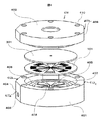
このように構成した流路蓋基板301と流路溝基板101とを収容するマイクロリアクタ400の一実施例を、図4〜図6を用いて説明する。図4はマイクロリアクタ400の分解斜視図であり、図5はマイクロリアクタ400の斜視図、そして図6はマイクロリアクタ400の縦断面図であり、図5のA−A断面図である。
An example of the
図4および図6に示すように、マイクロリアクタ400は、中央部に凹部が形成され下側に配置される入口筐体部材401の凹部に、上側に配置される出口筐体部材402の凸部が嵌合している。入口筐体部材401の凹部には、下側から順に流路溝基板101、次いで流路蓋基板301が収容されている。この流路溝基板101および流路蓋基板301を周方向に位置決めするために、入口筐体部材401の凹部は対向する2辺を切り欠いた円柱形状になっている。
As shown in FIGS. 4 and 6, the
入口筐体部材401の凹部上面の中心部には、流路溝基板101に形成した扇形状溝102に対応する位置に、ほぼ扇形状溝102と同形状の第1の溶液用プール部405が周方向に間隔をおいて配置されている。この第1の溶液用プール部間には、扇形の支持土手408が形成されている。第1の溶液用プール部405の外周側には、第1の溶液10と第2の溶液20の仕切り土手407を挟んで、リング状の第2の溶液用プール部406が形成されている。これら第1、第2の溶液用プール部405、406の深さは、流路溝基板101や流路蓋基板301の厚さに比べて十分大きい。
At the center of the upper surface of the concave portion of the
なお、第1の溶液用プール部405の外径は、第1の溶液の分岐流入孔104よりも外径側で第2の溶液の分岐流入孔105よりも内径側である。第2の溶液用プール部406は、内径位置が第1の分岐流入孔104よりも外径側で、外径位置が第2の溶液の分岐流入孔105よりも外径側である。
The outer diameter of the first
入口筐体部材401の中心部には、流路溝基板101の中心合流部107に対応する位置に、上面側から下方に止まり穴601が形成されている。入口筐体部材401は、円板を周方向複数箇所で切り欠いた形状をしている。この切り欠きにより形成された切り欠き面412a〜412cの1面412aに形成した水平方向穴411aが、この止まり穴601に連通している。これらの穴411a、601は、第1の溶液10の流入路を形成する。
A
同様に、第2の溶液用プール部406には、入口筐体部材401の上面側から下方に止まり穴603bが形成されている。この止まり穴603bに、切り欠き面412aに隣り合って形成された切り欠き面412bから入口筐体部材401の中心側に水平方向に延びる水平方向穴411bが、連通している。これらの穴603b、411bは、第2の溶液20の流入路を形成する。
Similarly, a blind hole 603b is formed in the second
出口筐体部材402の中央部には、下面側から上方に延びる止まり穴604が形成されている。この止まり穴604には、切り欠き面412a、412bとほぼ反対側に形成された切り欠き面412cから出口筐体部材402の中心部に水平方向に延びる水平方向穴411cが連通している。これらの穴604、411cは、流路蓋基板301の混合・反応溶液の流出孔302とともに、混合・反応溶液30の流出路を形成する。
A
出口筐体部材402の外周近傍には、この出口筐体部材402と入口筐体部材401とを組み立てた後、ボルト501で固定するためのボルト穴401が周方向に間隔をおいて複数個形成されている。入口筐体部材401の対応する位置には、ねじ穴410bが形成されている。
In the vicinity of the outer periphery of the
図5に示すように、第1の溶液10用の水平方向穴411aの入口部403には、継ぎ手503が取り付けられている。継ぎ手503には、チューブ502が取り付け可能であり、第1の溶液10をマイクロリアクタ400に導く。第2の溶液20用の水平方向穴411bの入口部404にも継ぎ手505が取り付けられており、この継ぎ手にチューブ504が接続されて第2の溶液20をマイクロリアクタ400に導く。混合・反応溶液30用の水平方向穴411cの出口部409には継ぎ手507が取り付けられており、この継ぎ手507にチューブ506が接続されており、流路溝基板101で混合・反応した溶液がこのチューブ506から外部に流出可能になっている。
As shown in FIG. 5, a joint 503 is attached to the
このように構成したマイクロリアクタ400では、マイクロリアクタ400外に保持された第1の溶液10が、第1の溶液10の入口部403から止まり穴601(図6参照)へ流入し、入口筐体部材401の中央部に位置する第1の溶液10のプール部405に導かれる。その後、第1の溶液10の分岐流入孔104を経て48本の流れに分岐して中心合流部107に流れ込む。
In the
それとともに、マイクロリアクタ400外に保持した第2の溶液20は、第2の溶液20の入口部404から第2の溶液用プール部406に導かれる。その後、第2の溶液20の分岐流入孔105を経て48本の流れに分岐して中心合流部107に流れ込む。中心合流部107に流れ込む第1、第2の溶液10、20は、上述したように流路溝基板101に形成した流路溝102において混合および/または反応して、混合・反応溶液30となる。
At the same time, the
混合・反応溶液30は、中心合流部107から、流路蓋基板301に形成した流出孔302を経て、混合・反応溶液の止まり穴604(図6参照)を垂直上方に流れる。その後水平方向に90°向きを変えて、出口筐体部材402に形成された混合・反応溶液の出口部409から、マイクロリアクタ400外に取り出される。
The mixed /
ここで、図5に示す流路溝基板101、流路蓋基板301、入口筐体部材401および出口筐体部材402は、接触面を鏡面仕上げにしており、入口筐体部材401と出口筐体部材402とをボルト501締結することにより、これら各部材101、301、401、402間を圧着させる。これにより、シール性が確保される。流路溝基板101や流路蓋基板301に使用する基板の材質や、マイクロリアクタ400に加わる圧力に応じて、流路溝基板101と流路蓋基板301との接触方法を変えることができる。すなわち、それらの基板がガラスであれば溶着し、それらの基板が金属であれば拡散接合して、シール性を確保してもよい。
Here, the
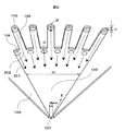
上述したマイクロリアクタ400を用いた実験システムの一実施例を、図7に模式図で示す。マイクロリアクタ701には、第1の溶液10を導入するための継ぎ手503にチューブ502が取り付けられている。チューブ502の途中には、チューブ502内を流通する第1の溶液10を加熱するコイル状に形成された予熱部702が設けられている。同様に、第2の溶液20を導入する継ぎ手505にはチューブ504が取り付けられており、チューブ504の途中にはチューブ504内を流通する第2の溶液20を加熱するコイル状に形成された予熱部703が設けられている。さらに、混合・反応溶液30をマイクロリアクタ30から排出するために継ぎ手507にチューブ506が取り付けられており、チューブ506の途中にはコイル状に形成された反応時間調整部704が設けられている。
An example of an experimental system using the
マイクロリアクタ701および予熱部702、703、反応時間調整部704は、恒温水槽705内に収容される。恒温水槽705には、水温調節部706が付設されており、常に恒温水槽705内の水を、図示しない加熱源および冷却源を用いて、所定温度に調節する。恒温水槽705内で、マイクロリアクタ701全体が液に漬かるように、恒温水槽705内の液量を調節して液面707を監視する。
The
第1の溶液10をマイクロリアクタ701に送液するために、チューブ502は恒温水槽705外に配置したシリンジポンプ等の送液ポンプ708に接続されている。送液ポンプ708は、第1の溶液タンク711にもチューブで接続されている。第2の溶液20をマイクロリアクタ701に送液するために、チューブ504は恒温水槽705外に配置したシリンジポンプ等の送液ポンプ709に接続されている。送液ポンプ709は、第2の溶液タンク712にもチューブで接続されている。送液ポンプ708、709はともに、プランジャー710を2個づつ有しており、プランジャー710の動作タイミングを調整して脈動を低減する。
In order to send the
マイクロリアクタ701内で生成された混合・反応溶液は、反応時間調整部704を経た後、高温水槽705外に配置されたタンク713にチューブで導かれる。本実験システムでは、第1、第2の溶液10、20の種類とその濃度等を選択することにより種々の化学反応系の実験が可能であり、これら選択した化学反応系に応じて、恒温水槽705の温度や送液ポンプ708、709の送液量を、図示しない制御手段が制御する。
The mixed / reaction solution generated in the microreactor 701 passes through the reaction
図8に、図7に示した実験システムを用いて実験したときの、マイクロリアクタ701内の流れ状態の一例を示す。扇形状溝102内で、第1の溶液10の層状流れ801(網掛け部)と第2の溶液の層状流れ802(白紙部分)は、周方向に多層化状態で流れ、徐々にその流れ幅を減少した縮流となって中心部に向かう。第1の溶液10と第2の溶液20は、中心部に向かうに従い、幅方向の端側から混合および/または反応して、中心合流部107のかなり上流側803で、すでに第1の溶液10および第2の溶液20全体が、混合および/または反応する。したがって、効率よく、混合・反応が推進される。
FIG. 8 shows an example of a flow state in the
上記実施例においては、扇形状溝を設けているが、第1の溶液と第2の溶液とが流れ方向に直角な方向の端部である幅方向端面で混合するような構造であれば、扇形状溝に限るものではなく、例えば流れの途中をより絞ったベル状やラッパ状であってもよい。ただしその場合においても、流路の拡大や急激な縮流の発生を防止する必要があることはいうまでもない。 In the above embodiment, a fan-shaped groove is provided, but if the structure is such that the first solution and the second solution are mixed at the end face in the width direction, which is the end in the direction perpendicular to the flow direction, The shape is not limited to the fan-shaped groove, and may be, for example, a bell shape or a trumpet shape that is further narrowed in the middle of the flow. However, even in that case, it is needless to say that it is necessary to prevent the expansion of the flow path and the occurrence of a sudden contraction.
また、扇形状溝の個数は8個にしているが、これもマイクロリアクタの大きさや第1、第2の溶液の性状、反応条件に応じて変更することができる。そして、比較的圧力が低い条件で反応させるときは、扇形状溝間の隙間に対応する支持土手の負荷が小さくなるから、支持土手の割合を低減して、扇形状溝の割合を多くすることが可能になる。また、第1、第2の溶液の層状流れの幅に深く関係する分岐流入孔の径やそれに続く流路の幅を、上記実施例では500μmにしたが、これもそれに限るものではない。第1、第2の溶液の流動抵抗を無視できるような大きさまで、低減することが望ましい。このように流路幅を低減できれば、第1、第2の溶液の混合または反応の均一度が早期に高まり、より効果的に混合・反応させることができるとともに、マイクロリアクタを小径化できる。さらに上記実施例では、1個の扇形状溝に設ける分岐流入孔を6個ずつ計12個としたが、上述したように第1、第2の溶液の性状等に応じて変更可能である。 The number of fan-shaped grooves is eight, but this can also be changed according to the size of the microreactor, the properties of the first and second solutions, and the reaction conditions. And when reacting under relatively low pressure conditions, the load on the support bank corresponding to the gap between the fan-shaped grooves is reduced, so the ratio of the support bank is reduced and the ratio of the fan-shaped grooves is increased. Is possible. In addition, although the diameter of the branch inflow hole and the width of the subsequent flow path that are deeply related to the width of the laminar flow of the first and second solutions are set to 500 μm in the above embodiment, this is not limited to this. It is desirable to reduce the flow resistance of the first and second solutions to a level that can be ignored. If the flow path width can be reduced in this way, the uniformity of the mixing or reaction of the first and second solutions can be increased at an early stage, and the microreactor can be reduced in size while being able to mix and react more effectively. Furthermore, in the above embodiment, the number of branch inflow holes provided in one fan-shaped groove is 12 in total, but 12 can be changed according to the properties of the first and second solutions as described above.
以上述べたように、本発明によれば、マイクロリアクタを用いた2液の化学反応装置において、2液を円周上に交互に配置する多層化構造とし、さらに基板の中心からの距離Rに応じて流路幅が徐々に減少する溝構造としたので、流路チップの大きさをコンパクトにしても圧力損失が少なく、処理流量を従来の構造に比べて増大可能である。 As described above, according to the present invention, in a two-component chemical reaction apparatus using a microreactor, a multilayered structure in which two solutions are alternately arranged on the circumference is provided, and further, according to the distance R from the center of the substrate. Therefore, even if the size of the channel chip is made compact, the pressure loss is small and the processing flow rate can be increased as compared with the conventional structure.
101…流路溝基板、102…扇形状溝、103…仕切り壁、104…(第1の)分岐流入孔、105…(第2の)分岐流入孔、106…第2の溶液の流路、107…中心合流部、201…第1の溶液の流れ、202…第2の溶液の流れ、301…流路蓋基板、302…混合・反応溶液の流出孔、401…入口筐体部材、402…出口筐体部材、403…第1の溶液の入口部、404…第2の溶液の入口部、405…第1の溶液のプール部、406…第2の溶液のプール部、407…仕切り土手、408…支持土手、409…混合・反応溶液の出口部、410…ボルト孔、501…ボルト、502…チューブ、503…継ぎ手、504…チューブ、505…継ぎ手、506…混合・反応溶液のチューブ、507…継ぎ手、601…止まり穴、602…第1の溶液の流れ、603…第2の溶液の流れ、604…止まり穴、605…混合・反応溶液の流れ、701…マイクロリアクタ、702、予熱部、704…反応時間調整部、705…恒温水槽、706…水温調節部、707…液面、708、709…送液ポンプ、710…プランジャー、711〜713…タンク、801…第1の溶液の層状流れ、802…第2の溶液の層状流れ、803…反応・混合溶液。
DESCRIPTION OF
Claims (4)
前記複数個の流路溝の各々は、
前記流路溝基板の周方向に形成され、前記中心合流部で互いに連結され、流路の幅が前記流路基板の外周側から前記中心合流部に至るまで徐々に狭くなるように形成された扇形状の流路溝で構成された複数個の第1の溶液流路溝と、
前記第1の溶液流路溝の外縁部から外方へ放射状かつ半径方向に形成された複数個の第2の溶液流路溝と、
前記複数個の第1の溶液流路溝の各々の外縁部において、周方向に設けられ、前記流路溝基板の裏面側まで貫通し、前記第1の溶液が導入される第1の分岐流入孔と、
前記複数個の第2の溶液流路溝の各々の外縁部に設けられ、前記流路溝基板の裏面側まで貫通し、前記第2の溶液が導入される第2の分岐流入孔とを備え、
前記複数個の流路溝の各々の間に、円板状基板の中心の極一部を除いた位置まで延伸された仕切り壁が形成され、
前記第1の分岐流入孔から導入された前記第1の溶液と前記第2の分岐流入孔から導入された前記第2の溶液とは、前記流路溝を外径側から内径側へ移動し、その途中において混合反応し、前記中心合流部を介して前記流出孔から流出するものであって、
更に、
中央部に凹部が形成された入口筐体部材と、
前記入口筐体部材の上側に配置された前記凹部に凸部が嵌合する出口筐体部材とを備え、
前記入口筐体部材の凹部には、下側から順に前記流路溝基板,前記流路蓋基板が収容され、
前記第1の溶液及び第2の溶液は、前記入口筐体部材に設けられた入口部から導かれ、前記流出孔を経て前記出口筐体部材に形成された出口部から取り出されることを特徴とするマイクロ化学反応装置。 A disc-shaped flow channel substrate having a plurality of flow channels formed in a radial direction with a predetermined depth on a predetermined surface side, and the plurality of flow channels are sealed, and an outflow hole is formed at the center. A flow path lid substrate formed, and the first and second solutions are allowed to flow from the outer peripheral side of the flow path groove toward the central portion, and the outflow hole is provided via a central merging portion provided in the central portion. A microchemical reaction device that flows out from
Each of the plurality of channel grooves is
Formed in the circumferential direction of the flow path groove substrate, connected to each other at the central merging portion, and formed such that the width of the flow path gradually narrows from the outer peripheral side of the flow path substrate to the central merging portion. A plurality of first solution flow channel grooves formed of fan-shaped flow channel grooves;
A plurality of second solution flow channel grooves formed radially and radially outward from the outer edge of the first solution flow channel groove;
A first branch inflow that is provided in a circumferential direction at each outer edge of each of the plurality of first solution flow channel grooves, penetrates to the back surface side of the flow channel substrate, and is introduced with the first solution. Holes,
A second branch inflow hole provided in an outer edge portion of each of the plurality of second solution flow channel grooves, penetrating to the back surface side of the flow channel substrate, and into which the second solution is introduced. ,
Between each of the plurality of flow channel grooves, a partition wall is formed that extends to a position excluding the pole portion at the center of the disk-shaped substrate,
The first solution introduced from the first branch inflow hole and the second solution introduced from the second branch inflow hole move the flow channel from the outer diameter side to the inner diameter side. , Mixed reaction in the middle, flowing out from the outflow hole through the central merging portion ,
Furthermore,
An entrance housing member having a recess formed in the center,
An exit housing member having a convex portion fitted into the concave portion disposed on the upper side of the entrance housing member;
In the recess of the inlet housing member, the flow channel groove substrate and the flow channel lid substrate are accommodated in order from the lower side,
The first solution and the second solution are guided from an inlet portion provided in the inlet casing member, and are taken out from an outlet portion formed in the outlet casing member through the outlet hole. Micro chemical reaction device.
前記複数個の流路溝の各々は、Each of the plurality of channel grooves is
前記流路溝基板の周方向に形成され、前記中心合流部で互いに連結され、流路の幅が前記流路基板の外周側から前記中心合流部に至るまで徐々に狭くなるように形成された扇形状の流路溝で構成された複数個の第1の溶液流路溝と、Formed in the circumferential direction of the flow path groove substrate, connected to each other at the central merging portion, and formed such that the width of the flow path gradually narrows from the outer peripheral side of the flow path substrate to the central merging portion. A plurality of first solution flow channel grooves composed of fan-shaped flow channel grooves;
前記第1の溶液流路溝の外縁部から外方へ放射状かつ半径方向に形成された複数個の第2の溶液流路溝と、A plurality of second solution flow channel grooves formed radially and radially outward from the outer edge of the first solution flow channel groove;
前記複数個の第1の溶液流路溝の各々の外縁部において、周方向に設けられ、前記流路溝基板の裏面側まで貫通し、前記第1の溶液が導入される第1の分岐流入孔と、A first branch inflow that is provided in a circumferential direction at each outer edge of each of the plurality of first solution flow channel grooves, penetrates to the back surface side of the flow channel substrate, and is introduced with the first solution. Holes,
前記複数個の第2の溶液流路溝の各々の外縁部に設けられ、前記流路溝基板の裏面側まで貫通し、前記第2の溶液が導入される第2の分岐流入孔とを備え、A second branch inflow hole provided in an outer edge portion of each of the plurality of second solution flow channel grooves, penetrating to the back surface side of the flow channel substrate, and into which the second solution is introduced. ,
前記複数個の流路溝の各々の間に、円板状基板の中心の極一部を除いた位置まで延伸された仕切り壁が形成され、Between each of the plurality of flow channel grooves, a partition wall is formed that extends to a position excluding a part of the center of the disk-shaped substrate,
前記第1の分岐流入孔から導入された前記第1の溶液と前記第2の分岐流入孔から導入された前記第2の溶液とは、前記流路溝を外径側から内径側へ移動し、その途中において混合反応し、前記中心合流部を介して前記流出孔から流出するものであって、The first solution introduced from the first branch inflow hole and the second solution introduced from the second branch inflow hole move the flow channel from the outer diameter side to the inner diameter side. , Mixed reaction in the middle, flowing out from the outflow hole through the central merging portion,
更に、Furthermore,
中央部に凹部が形成された入口筐体部材と、An inlet housing member having a recess formed in the center,
前記入口筐体部材の上側に配置された前記凹部に凸部が嵌合する出口筐体部材とを備え、An exit housing member in which a convex portion fits into the concave portion disposed on the upper side of the entrance housing member;
前記入口筐体部材の凹部には、下側から順に前記流路溝基板,前記流路蓋基板が収容され、In the recess of the inlet housing member, the flow path groove substrate and the flow path lid substrate are accommodated in order from the lower side,
前記流路溝基板,前記流路蓋基板,前記入口筐体部材及び前記出口筐体部材は、接触面を鏡面上げされ、前記入口筐体部材と前記出口筐体部材とがボルトで締結されたことを特徴とするマイクロ化学反応装置。The flow channel substrate, the flow channel lid substrate, the inlet housing member, and the outlet housing member are mirror-finished on the contact surfaces, and the inlet housing member and the outlet housing member are fastened with bolts. A microchemical reaction device characterized by that.
前記複数個の流路溝の各々は、Each of the plurality of channel grooves is
前記流路溝基板の周方向に形成され、前記中心合流部で互いに連結され、流路の幅が前記流路基板の外周側から前記中心合流部に至るまで徐々に狭くなるように形成された扇形状の流路溝で構成された複数個の第1の溶液流路溝と、Formed in the circumferential direction of the flow path groove substrate, connected to each other at the central merging portion, and formed such that the width of the flow path gradually narrows from the outer peripheral side of the flow path substrate to the central merging portion. A plurality of first solution flow channel grooves composed of fan-shaped flow channel grooves;
前記第1の溶液流路溝の外縁部から外方へ放射状かつ半径方向に形成された複数個の第2の溶液流路溝と、A plurality of second solution flow channel grooves formed radially and radially outward from the outer edge of the first solution flow channel groove;
前記複数個の第1の溶液流路溝の各々の外縁部において、周方向に設けられ、前記流路溝基板の裏面側まで貫通し、前記第1の溶液が導入される第1の分岐流入孔と、A first branch inflow that is provided in a circumferential direction at each outer edge of each of the plurality of first solution flow channel grooves, penetrates to the back surface side of the flow channel substrate, and is introduced with the first solution. Holes,
前記複数個の第2の溶液流路溝の各々の外縁部に設けられ、前記流路溝基板の裏面側まで貫通し、前記第2の溶液が導入される第2の分岐流入孔とを備え、A second branch inflow hole provided in an outer edge portion of each of the plurality of second solution flow channel grooves, penetrating to the back surface side of the flow channel substrate, and into which the second solution is introduced. ,
前記複数個の流路溝の各々の間に、円板状基板の中心の極一部を除いた位置まで延伸された仕切り壁が形成され、Between each of the plurality of flow channel grooves, a partition wall is formed that extends to a position excluding a part of the center of the disk-shaped substrate,
前記第1の分岐流入孔から導入された前記第1の溶液と前記第2の分岐流入孔から導入された前記第2の溶液とは、前記流路溝を外径側から内径側へ移動し、その途中において混合反応し、前記中心合流部を介して前記流出孔から流出するものであって、The first solution introduced from the first branch inflow hole and the second solution introduced from the second branch inflow hole move the flow channel from the outer diameter side to the inner diameter side. , Mixed reaction in the middle, flowing out from the outflow hole through the central merging portion,
更に、Furthermore,
中央部に凹部が形成された入口筐体部材と、An inlet housing member having a recess formed in the center,
前記入口筐体部材の上側に配置された前記凹部に凸部が嵌合する出口筐体部材とを備え、An exit housing member in which a convex portion fits into the concave portion disposed on the upper side of the entrance housing member;
前記入口筐体部材の凹部には、下側から順に前記流路溝基板,前記流路蓋基板が収容され、In the recess of the inlet housing member, the flow path groove substrate and the flow path lid substrate are accommodated in order from the lower side,
前記流路溝基板及び前記流路蓋基板は円板の対向する2面に切り欠き部が形成され、前記凹部は対向する2辺を切り欠いた円柱形状とされたことを特徴とするマイクロ化学反応装置。The channel groove substrate and the channel lid substrate have a notch formed in two opposing surfaces of a disk, and the recess has a cylindrical shape with two opposing sides cut out. Reactor.
前記複数個の流路溝の各々は、Each of the plurality of channel grooves is
前記流路溝基板の周方向に形成され、前記中心合流部で互いに連結され、流路の幅が前記流路基板の外周側から前記中心合流部に至るまで徐々に狭くなるように形成された扇形状の流路溝で構成された複数個の第1の溶液流路溝と、Formed in the circumferential direction of the flow path groove substrate, connected to each other at the central merging portion, and formed such that the width of the flow path gradually narrows from the outer peripheral side of the flow path substrate to the central merging portion. A plurality of first solution flow channel grooves composed of fan-shaped flow channel grooves;
前記第1の溶液流路溝の外縁部から外方へ放射状かつ半径方向に形成された複数個の第2の溶液流路溝と、A plurality of second solution flow channel grooves formed radially and radially outward from the outer edge of the first solution flow channel groove;
前記複数個の第1の溶液流路溝の各々の外縁部において、周方向に設けられ、前記流路溝基板の裏面側まで貫通し、前記第1の溶液が導入される第1の分岐流入孔と、A first branch inflow that is provided in a circumferential direction at each outer edge of each of the plurality of first solution flow channel grooves, penetrates to the back surface side of the flow channel substrate, and is introduced with the first solution. Holes,
前記複数個の第2の溶液流路溝の各々の外縁部に設けられ、前記流路溝基板の裏面側まで貫通し、前記第2の溶液が導入される第2の分岐流入孔とを備え、A second branch inflow hole provided in an outer edge portion of each of the plurality of second solution flow channel grooves, penetrating to the back surface side of the flow channel substrate, and into which the second solution is introduced. ,
前記複数個の流路溝の各々の間に、円板状基板の中心の極一部を除いた位置まで延伸された仕切り壁が形成され、Between each of the plurality of flow channel grooves, a partition wall is formed that extends to a position excluding a part of the center of the disk-shaped substrate,
前記第1の分岐流入孔から導入された前記第1の溶液と前記第2の分岐流入孔から導入された前記第2の溶液とは、前記流路溝を外径側から内径側へ移動し、その途中において混合反応し、前記中心合流部を介して前記流出孔から流出するものであって、The first solution introduced from the first branch inflow hole and the second solution introduced from the second branch inflow hole move the flow channel from the outer diameter side to the inner diameter side. , Mixed reaction in the middle, flowing out from the outflow hole through the central merging portion,
更に、Furthermore,
中央部に凹部が形成された入口筐体部材と、An inlet housing member having a recess formed in the center,
前記入口筐体部材の上側に配置された前記凹部に凸部が嵌合する出口筐体部材とを備え、An exit housing member in which a convex portion fits into the concave portion disposed on the upper side of the entrance housing member;
前記入口筐体部材の凹部には、下側から順に前記流路溝基板,前記流路蓋基板が収容され、In the recess of the inlet housing member, the flow path groove substrate and the flow path lid substrate are accommodated in order from the lower side,
前記凹部上面の前記扇形状溝に対応し、外径が前記第1の分岐流入孔よりも外径側で前記の第2の分岐流入孔よりも内径側の位置に配置された第1の溶液用プール部と、A first solution corresponding to the fan-shaped groove on the upper surface of the recess and having an outer diameter located on the outer diameter side of the first branch inflow hole and on the inner diameter side of the second branch inflow hole. Pool section,
前記第1の溶液用プール部間に形成された扇状の支持土手と、A fan-shaped support bank formed between the first solution pool parts;
前記第1の溶液用プール部の外周側にリング状として形成され、内径位置が前記第1の分岐流入孔よりも外径側で、外径位置が前記第2の分岐流入孔よりも外径側とされた第2の溶液用プール部とを備えたことを特徴とするマイクロ化学反応装置。The first solution pool portion is formed in a ring shape on the outer peripheral side, the inner diameter position is on the outer diameter side of the first branch inflow hole, and the outer diameter position is the outer diameter of the second branch inflow hole. A microchemical reaction device comprising: a second solution pool portion on the side.
Priority Applications (2)
| Application Number | Priority Date | Filing Date | Title |
|---|---|---|---|
| JP2005260032A JP4715403B2 (en) | 2005-09-08 | 2005-09-08 | Micro chemical reactor |
| EP06017640A EP1762298B1 (en) | 2005-09-08 | 2006-08-24 | Two-solution microreactor having sector-shaped grooves |
Applications Claiming Priority (1)
| Application Number | Priority Date | Filing Date | Title |
|---|---|---|---|
| JP2005260032A JP4715403B2 (en) | 2005-09-08 | 2005-09-08 | Micro chemical reactor |
Publications (3)
| Publication Number | Publication Date |
|---|---|
| JP2007069137A JP2007069137A (en) | 2007-03-22 |
| JP2007069137A5 JP2007069137A5 (en) | 2008-07-10 |
| JP4715403B2 true JP4715403B2 (en) | 2011-07-06 |
Family
ID=37497886
Family Applications (1)
| Application Number | Title | Priority Date | Filing Date |
|---|---|---|---|
| JP2005260032A Active JP4715403B2 (en) | 2005-09-08 | 2005-09-08 | Micro chemical reactor |
Country Status (2)
| Country | Link |
|---|---|
| EP (1) | EP1762298B1 (en) |
| JP (1) | JP4715403B2 (en) |
Cited By (1)
| Publication number | Priority date | Publication date | Assignee | Title |
|---|---|---|---|---|
| JP2008043912A (en) * | 2006-08-21 | 2008-02-28 | Hitachi Ltd | Microreactor |
Families Citing this family (4)
| Publication number | Priority date | Publication date | Assignee | Title |
|---|---|---|---|---|
| JP5081845B2 (en) | 2009-02-10 | 2012-11-28 | 株式会社日立製作所 | Particle production equipment |
| JP2010247071A (en) | 2009-04-16 | 2010-11-04 | Hitachi Plant Technologies Ltd | Fluid mixer |
| WO2010131297A1 (en) | 2009-05-14 | 2010-11-18 | 株式会社日立プラントテクノロジー | Microreactor system |
| CA3082685A1 (en) | 2017-11-16 | 2019-05-23 | Societe De Commercialisation Des Produits De La Recherche Appliquee Socpra Sciences Et Genie S.E.C. | Integrated solar micro-reactors for hydrogen synthesis via steam methane reforming |
Citations (3)
| Publication number | Priority date | Publication date | Assignee | Title |
|---|---|---|---|---|
| WO1997000125A1 (en) * | 1995-06-16 | 1997-01-03 | Novartis Ag | Flow cell for the passive mixing of flowable substances |
| JP2004113968A (en) * | 2002-09-27 | 2004-04-15 | Fuji Electric Systems Co Ltd | Micromixer |
| JP2004148277A (en) * | 2002-11-01 | 2004-05-27 | Hitachi Ltd | Chemical reaction apparatus |
Family Cites Families (6)
| Publication number | Priority date | Publication date | Assignee | Title |
|---|---|---|---|---|
| US5887977A (en) * | 1997-09-30 | 1999-03-30 | Uniflows Co., Ltd. | Stationary in-line mixer |
| GB9809943D0 (en) * | 1998-05-08 | 1998-07-08 | Amersham Pharm Biotech Ab | Microfluidic device |
| DE10123093A1 (en) * | 2001-05-07 | 2002-11-21 | Inst Mikrotechnik Mainz Gmbh | Method and static micromixer for mixing at least two fluids |
| DE10123092B4 (en) * | 2001-05-07 | 2005-02-10 | INSTITUT FüR MIKROTECHNIK MAINZ GMBH | Method and static mixer for mixing at least two fluids |
| JP2003126686A (en) * | 2001-10-26 | 2003-05-07 | Fuji Photo Film Co Ltd | Laser heating microreactor |
| DE10333922B4 (en) * | 2003-07-25 | 2005-11-17 | Wella Ag | Components for static micromixers, micromixers constructed therefrom and their use for mixing, dispersing or for carrying out chemical reactions |
-
2005
- 2005-09-08 JP JP2005260032A patent/JP4715403B2/en active Active
-
2006
- 2006-08-24 EP EP06017640A patent/EP1762298B1/en not_active Expired - Fee Related
Patent Citations (3)
| Publication number | Priority date | Publication date | Assignee | Title |
|---|---|---|---|---|
| WO1997000125A1 (en) * | 1995-06-16 | 1997-01-03 | Novartis Ag | Flow cell for the passive mixing of flowable substances |
| JP2004113968A (en) * | 2002-09-27 | 2004-04-15 | Fuji Electric Systems Co Ltd | Micromixer |
| JP2004148277A (en) * | 2002-11-01 | 2004-05-27 | Hitachi Ltd | Chemical reaction apparatus |
Cited By (1)
| Publication number | Priority date | Publication date | Assignee | Title |
|---|---|---|---|---|
| JP2008043912A (en) * | 2006-08-21 | 2008-02-28 | Hitachi Ltd | Microreactor |
Also Published As
| Publication number | Publication date |
|---|---|
| EP1762298B1 (en) | 2012-01-18 |
| EP1762298A1 (en) | 2007-03-14 |
| JP2007069137A (en) | 2007-03-22 |
Similar Documents
| Publication | Publication Date | Title |
|---|---|---|
| CA2646863C (en) | Micro-reactor system | |
| JP4715403B2 (en) | Micro chemical reactor | |
| KR100845200B1 (en) | Apparatus for mixing and reacting at least two fluids | |
| JP4339163B2 (en) | Microdevice and fluid merging method | |
| EP0853490B1 (en) | Micro-mixer | |
| US6935768B2 (en) | Method and statistical micromixer for mixing at least two liquids | |
| US6863867B2 (en) | Apparatus for mixing and reacting at least two fluids | |
| JP2010046634A (en) | Reactor and reaction plant | |
| US6655829B1 (en) | Static mixer and process for mixing at least two fluids | |
| JP4803671B2 (en) | Static micro mixer | |
| US20030039169A1 (en) | Micromixer | |
| KR20070106712A (en) | High performance microreactor | |
| EP1997553A2 (en) | Fluid mixer and method for forming mixed fluid | |
| JP5470642B2 (en) | Micro droplet preparation device | |
| JP2006239638A (en) | Mixer and mixing method | |
| US20090034362A1 (en) | Microdevice and method for joining fluids | |
| Kriel et al. | Numbering-up Y–Y microfluidic chips for higher-throughput solvent extraction of platinum (IV) chloride | |
| KR100818564B1 (en) | Emulsifying and separating device for liquid phases | |
| KR20070113241A (en) | Method for producing chemicals | |
| KR20100127805A (en) | Injector assemblies and microreactors incorporating the same | |
| WO2012046389A1 (en) | Flow path structure | |
| JP3888275B2 (en) | Micro mixer | |
| JP2010000428A (en) | Microreactor | |
| JP2006051410A (en) | Micro-reactor | |
| JP2004113967A (en) | Micromixer |
Legal Events
| Date | Code | Title | Description |
|---|---|---|---|
| A521 | Request for written amendment filed |
Free format text: JAPANESE INTERMEDIATE CODE: A821 Effective date: 20061204 |
|
| A521 | Request for written amendment filed |
Free format text: JAPANESE INTERMEDIATE CODE: A523 Effective date: 20080328 |
|
| A621 | Written request for application examination |
Free format text: JAPANESE INTERMEDIATE CODE: A621 Effective date: 20080328 |
|
| A521 | Request for written amendment filed |
Free format text: JAPANESE INTERMEDIATE CODE: A523 Effective date: 20080328 |
|
| A521 | Request for written amendment filed |
Free format text: JAPANESE INTERMEDIATE CODE: A523 Effective date: 20080519 |
|
| RD02 | Notification of acceptance of power of attorney |
Free format text: JAPANESE INTERMEDIATE CODE: A7422 Effective date: 20080519 |
|
| A977 | Report on retrieval |
Free format text: JAPANESE INTERMEDIATE CODE: A971007 Effective date: 20090724 |
|
| A131 | Notification of reasons for refusal |
Free format text: JAPANESE INTERMEDIATE CODE: A131 Effective date: 20101130 |
|
| A521 | Request for written amendment filed |
Free format text: JAPANESE INTERMEDIATE CODE: A523 Effective date: 20110113 |
|
| TRDD | Decision of grant or rejection written | ||
| A01 | Written decision to grant a patent or to grant a registration (utility model) |
Free format text: JAPANESE INTERMEDIATE CODE: A01 Effective date: 20110301 |
|
| A61 | First payment of annual fees (during grant procedure) |
Free format text: JAPANESE INTERMEDIATE CODE: A61 Effective date: 20110314 |
|
| R150 | Certificate of patent or registration of utility model |
Ref document number: 4715403 Country of ref document: JP Free format text: JAPANESE INTERMEDIATE CODE: R150 Free format text: JAPANESE INTERMEDIATE CODE: R150 |
|
| FPAY | Renewal fee payment (event date is renewal date of database) |
Free format text: PAYMENT UNTIL: 20140408 Year of fee payment: 3 |
|
| S111 | Request for change of ownership or part of ownership |
Free format text: JAPANESE INTERMEDIATE CODE: R313111 |
|
| R350 | Written notification of registration of transfer |
Free format text: JAPANESE INTERMEDIATE CODE: R350 |
|
| R250 | Receipt of annual fees |
Free format text: JAPANESE INTERMEDIATE CODE: R250 |
|
| R250 | Receipt of annual fees |
Free format text: JAPANESE INTERMEDIATE CODE: R250 |
|
| S111 | Request for change of ownership or part of ownership |
Free format text: JAPANESE INTERMEDIATE CODE: R313113 |
|
| R350 | Written notification of registration of transfer |
Free format text: JAPANESE INTERMEDIATE CODE: R350 |
|
| R250 | Receipt of annual fees |
Free format text: JAPANESE INTERMEDIATE CODE: R250 |
|
| R250 | Receipt of annual fees |
Free format text: JAPANESE INTERMEDIATE CODE: R250 |
|
| R250 | Receipt of annual fees |
Free format text: JAPANESE INTERMEDIATE CODE: R250 |
|
| R250 | Receipt of annual fees |
Free format text: JAPANESE INTERMEDIATE CODE: R250 |