EP1997553A2 - Fluid mixer and method for forming mixed fluid - Google Patents
Fluid mixer and method for forming mixed fluid Download PDFInfo
- Publication number
- EP1997553A2 EP1997553A2 EP08009659A EP08009659A EP1997553A2 EP 1997553 A2 EP1997553 A2 EP 1997553A2 EP 08009659 A EP08009659 A EP 08009659A EP 08009659 A EP08009659 A EP 08009659A EP 1997553 A2 EP1997553 A2 EP 1997553A2
- Authority
- EP
- European Patent Office
- Prior art keywords
- fluid
- paths
- bifurcation
- path
- flow
- Prior art date
- Legal status (The legal status is an assumption and is not a legal conclusion. Google has not performed a legal analysis and makes no representation as to the accuracy of the status listed.)
- Granted
Links
Images


Classifications
-
- B—PERFORMING OPERATIONS; TRANSPORTING
- B01—PHYSICAL OR CHEMICAL PROCESSES OR APPARATUS IN GENERAL
- B01F—MIXING, e.g. DISSOLVING, EMULSIFYING OR DISPERSING
- B01F25/00—Flow mixers; Mixers for falling materials, e.g. solid particles
- B01F25/40—Static mixers
- B01F25/42—Static mixers in which the mixing is affected by moving the components jointly in changing directions, e.g. in tubes provided with baffles or obstructions
- B01F25/43—Mixing tubes, e.g. wherein the material is moved in a radial or partly reversed direction
- B01F25/432—Mixing tubes, e.g. wherein the material is moved in a radial or partly reversed direction with means for dividing the material flow into separate sub-flows and for repositioning and recombining these sub-flows; Cross-mixing, e.g. conducting the outer layer of the material nearer to the axis of the tube or vice-versa
- B01F25/4323—Mixing tubes, e.g. wherein the material is moved in a radial or partly reversed direction with means for dividing the material flow into separate sub-flows and for repositioning and recombining these sub-flows; Cross-mixing, e.g. conducting the outer layer of the material nearer to the axis of the tube or vice-versa using elements provided with a plurality of channels or using a plurality of tubes which can either be placed between common spaces or collectors
- B01F25/43231—Mixing tubes, e.g. wherein the material is moved in a radial or partly reversed direction with means for dividing the material flow into separate sub-flows and for repositioning and recombining these sub-flows; Cross-mixing, e.g. conducting the outer layer of the material nearer to the axis of the tube or vice-versa using elements provided with a plurality of channels or using a plurality of tubes which can either be placed between common spaces or collectors the channels or tubes crossing each other several times
-
- B—PERFORMING OPERATIONS; TRANSPORTING
- B01—PHYSICAL OR CHEMICAL PROCESSES OR APPARATUS IN GENERAL
- B01F—MIXING, e.g. DISSOLVING, EMULSIFYING OR DISPERSING
- B01F33/00—Other mixers; Mixing plants; Combinations of mixers
- B01F33/30—Micromixers
-
- B—PERFORMING OPERATIONS; TRANSPORTING
- B01—PHYSICAL OR CHEMICAL PROCESSES OR APPARATUS IN GENERAL
- B01F—MIXING, e.g. DISSOLVING, EMULSIFYING OR DISPERSING
- B01F33/00—Other mixers; Mixing plants; Combinations of mixers
- B01F33/80—Mixing plants; Combinations of mixers
- B01F33/81—Combinations of similar mixers, e.g. with rotary stirring devices in two or more receptacles
- B01F33/813—Combinations of similar mixers, e.g. with rotary stirring devices in two or more receptacles mixing simultaneously in two or more mixing receptacles
Definitions
- the present invention pertains to a technological field where two or more of fluids such as liquids and gases are mixed to obtain a mixed fluid. More specifically, the present invention relates to a technology to obtain this mixed fluid in the order of micrometer rapidly.
- This micro-reactor includes multiple flat plates appropriately stacked on each other. Each flat plate is provided therein with multiple flow paths as grooves, the flow paths being substantially Y-shaped, and being connected with each other. In this way, a bifurcation portion on the upper side of the Y form of one of the flow paths is connected to a convergence portion on the lower side of the Y form of another one of the flow paths (see, for example, Fig. 2 and Fig. 10 in Japanese Patent Translation Publication No. Hei. 11-511689 (Patent Document 1)).
- the number of flat plates provided with the through holes need to be increased to some degree, the plate being stacked on each other so as to homogenize the mixed fluid in the order of micrometer. Nevertheless, such an increase in the number of stacked flat plates increases the thickness of the micro-reactor, and decreases the controllability on the internal temperature of the reactor. In such a case, it becomes difficult to control the chemical reaction that proceeds while involving endothermic and exothermic reactions caused by the mixing of the two types of fluids.
- An object of the present invention is to provide: a compact fluid mixer having an excellent temperature controllability, and high productivity of forming a highly-homogenized mixed fluid; and a method for forming such a mixed fluid.
- the present invention provides a fluid mixer which forms a mixed fluid by mixing a first fluid and a second fluid.
- the multiple introduction paths into which a first fluid and a second fluid are introduced make it possible to treat mixtures of the two types of fluids in the multiple confluence paths arranged in parallel simultaneously.
- the multiple confluence paths arranged in parallel have the serial n number of stages with the bifurcation paths in between. Fluids are bifurcated after passing through the confluence paths at each stage. Half of the fluid thus bifurcated is converged with half of another fluid adjacent in the parallel direction, this adjacent fluid having been bifurcated similarly. These bifurcation and convergence are repeated to increase the degree of mixing the fluids without increasing the number of stages serially.
- the flow paths through which the first fluid, the second fluid, and the mixed fluids flow are easily formed highly densely, and also the flow paths can be formed on two or three substrates. Thereby, the flow paths occupy only a small space, and have more specific surfaces at the same time.
- the present invention makes it possible to provide: a fluid mixer which is small in size, and which has an excellent temperature controllability and a high productivity of forming a highly-homogenized mixed fluid; and a method for forming such a mixed fluid.
- Fig. 1 is an exploded perspective view showing a fluid mixer according to a first embodiment of the present invention.
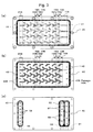
- Fig. 2 is a plan view showing a top view of flow paths provided in the fluid mixer according to the first embodiment.
- Figs. 3(a) to 3(c) are plan views showing top views of a first flow-path plate, a second flow-path plate, and a delivery plate, respectively, in the fluid mixer according to the first embodiment.
- Fig. 4(a) is a partially enlarged view of Fig. 2 according to the fluid mixer of the first embodiment;
- Fig. 4(b) is a cross-sectional view in a Y-direction of Fig. 4(a);
- Fig. 4(c) is a cross-sectional view in an X direction of Fig. 4(a) .
- Fig. 5 is an exploded perspective view showing a fluid mixer according to a second embodiment of the present invention.
- Fig. 6 is a plan view showing a top view of flow paths provided in the fluid mixer according to the second embodiment.
- Figs. 7(a) to 7(c) are plan views showing top views of a first flow-path plate, a third flow-path plate, and a second flow-path plate, respectively, in the fluid mixer according to the second embodiment.
- Fig. 8(a) is a partially enlarged view of Fig. 6 according to the fluid mixer of the second embodiment;
- Fig. 8(b) is a cross-sectional view in a Y-direction of Fig. 8(a);
- Fig. 8(c) is a cross-sectional view in an X direction of Fig. 8(a) .
- a fluid mixer 10 of the first embodiment is configured of a delivery plate 50 as well as a first flow-path plate 30 and a second flow-path plate 40 that are stacked on the delivery plate 50.
- the fluid mixer 10 configured in this manner receives a first fluid and a second fluid from inlet paths 51, 52, respectively, in the delivery plate 50. Then, the fluids flow through flow paths 31, 42 (see Fig. 2 as necessary) formed in the respective flow-path plates 30, 40, and the fluids are mixed with each other. Consequently, the fluid mixer 10 outputs the fluids as a mixed fluid from an outlet path 54 in the delivery plate 50.
- the first flow path 31 is formed into a groove shape by carving one surface (lower surface in the drawing) of the first flow-path plate 30.
- the second flow path 42 is formed into a groove shape by carving one surface (upper surface in the drawing) of the second flow-path plate 40.
- the first flow-path plate 30 and the second flow-path plate 40 are brought into contact with each other on those surfaces where the flow paths are carved. Thereby, formed are flow paths (see Fig. 2 as necessary) through which the first and second fluids flow and mix together.
- a sealing groove 33 is carved in the first flow-path plate 30 as surrounding the first flow path 31.
- a sealing groove 43 is carved in the second flow-path plate 40 as surrounding the second flow path 42. According, by inserting a sealing member 25 into the sealing grooves 33, 43, the fluids flowing through the first flow path 31 and the second flow path 42 are prevented from leaking out.
- sealing grooves 53, 53 are carved in the delivery plate 50.
- the sealing grooves are for inserting sealing members (unillustrated) disposed between the delivery plate 50 and the second flow-path plate 40.
- the sealing grooves 53, 53 are carved as surrounding a group of first dividing holes 57 through which the first fluid passes, a group of second dividing holes 58 through which the second fluid passes, and a group of third dividing holes 59 through which the mixed fluid passes.
- fastening holes 35, 45, 55 are provided at the respective peripheries of the first flow-path plate 30, the second flow-path plate 40 and the delivery plate 50.
- the fastening hole is for inserting a fastening member (the illustration is omitted) which fixes these plates stacked on each other.
- positioning holes 36, 46, 56 are provided for positioning the first flow path 31, the second flow path 42 and the dividing holes 57, 58, 59 as predetermined (see Fig. 2 as necessary).
- the material of the first flow-path plate 30, the second flow-path plate 40 and the delivery plate 50 can be appropriately selected among, for example, metals, silicon, glasses, plastic materials, in accordance with the fluids.
- the dimensions such as the width, depth, and the like of the flow paths 31, 42 preferably range from approximately several tens of ⁇ m to several mm.
- a method of etching, machine processing, or the like can be appropriately selected.
- the flow paths 31, 42 are disposed on a two-dimensional plane. Accordingly, the fluid mixer 10 is in a plate-like form, and has a large specific area as illustrated. Thus, the fluid mixer 10 has an excellent characteristic of a temperature controllability.
- the entire fluid mixer 10 may be installed in a thermostat (unillustrated), or the fluid mixer 10 may be provided on the top and bottom flat surfaces with a heat adjustment means such as a heater, a Peltier device or a hot water jacket (unillustrated).
- a heat adjustment means such as a heater, a Peltier device or a hot water jacket (unillustrated).
- Fig. 2 is a plan view showing a configuration of the flow paths observed from the top surface of the fluid mixer 10 according to the first embodiment, and the first flow path 31 and the second flow path 42 are superimposed on each other.
- the flow paths 31, 42 as shown in Fig. 2 , in which combinations between bifurcation paths 13, 15, 17, 19 and confluence paths 14, 16, 18, 20 are formed in multiple stages (12 stages in the drawing) in series in which the fluids flow, and in which combinations between the first-fluid introduction paths 11 and second-fluid introduction paths 12 are formed in multiple rows (4 rows in the drawing) in a parallel direction which is perpendicular to the serial direction.
- the first fluids are introduced from the first dividing holes 57 in the delivery plate 50 (see Fig. 1 ).
- the multiple first-fluid introduction paths 11 (4 in the drawing) are arranged in parallel to a direction perpendicular to the direction in which the first fluid flows, thereby forming a group.
- the second fluids are introduced from the second dividing holes 58 in the delivery plate 50 (see Fig. 1 ).
- the multiple second-fluid introduction paths 12 (4 in the drawing) are arranged alternately with the first-fluid introduction paths 11, thereby forming a group.
- the first bifurcation path 13 is formed of an end of the first-fluid introduction path 11 bifurcating into two in the first-fluid flowing direction, as well as an end of the second-fluid introduction path 12 bifurcating into two in the second-fluid flowing direction. These ends are disposed alternately in parallel, thereby forming a group of first bifurcation paths 13.
- the first confluence path 14 is formed by combining one of the two ends of a first bifurcation path 13 with one of the two ends of another (adjacent) first bifurcation path 13.
- the multiple first confluence paths 14 are disposed alternately in parallel, thereby forming a group.
- the second bifurcation path 15 is formed of the ends of the first confluence path 14 bifurcating into two in the fluid flowing direction.
- the multiple second bifurcation paths 15 are disposed in parallel, thereby forming a group.
- the second confluence path 16 is formed by combining one of the two ends of a second bifurcation path 15 with one of the two ends of another (adjacent) second bifurcation path 15.
- the multiple second confluence paths 16 are disposed in parallel, thereby forming a group.
- the flow paths 31, 42 are configured of an arbitrary number of stages (n stages) connected serially.
- the multiple nth bifurcation paths 19 are disposed in parallel, thereby forming a group.
- the nth confluence path 20 is formed by combining one of the two ends of an nth bifurcation path 19 with one of the two ends of another (adjacent) nth bifurcation path 19.
- the multiple nth confluence paths 20 are disposed alternately in parallel, thereby forming a group.
- a mixed-fluid discharging path 21 is formed of the nth confluence path 20 positioned at the end (last stage) of the fluid-flowing direction and extended.
- the mixed-fluid discharging path 21 is a portion to discharge the fluids mixed by repeatedly converging and dividing the first fluids and the second fluids at each stage multiple times (n times), and is connected with the third dividing hole 59 in the delivery plate 50 (see Fig. 1 ).
- Fig. 3(a) is a plan view showing the first flow-path plate 30 observed from the top surface of the fluid mixer 10 (see Fig. 1 ).
- the first flow paths 31 and the sealing groove 33 shown by dashed lines are carved in the opposite surface.
- Fig. 3(b) is a plan view showing the second flow-path plate 40 observed from the top surface of the fluid mixer 10.
- the flow paths 42 and the sealing groove 43 shown by solid lines are carved in this surface.
- Fig. 3(c) is a plan view showing the delivery plate 50 observed from the top surface of the fluid mixer 10 (see Fig. 1 ).
- the dividing holes 57, 58, 59 shown by solid lines are openings in this surface.
- the sealing grooves 53 are also carved in this surface.
- the first-fluid inlet path 51 communicates with the group of the first-fluid introduction paths 11A on the first flow-path plate 30 via the first dividing holes 57 of the delivery plate 50 and passage holes 47B of the second flow-path plate 40.
- this first fluid is introduced into the first-fluid introduction paths 11A.
- the second-fluid inlet path 52 communicates with the group of the second-fluid introduction paths 12B on the second flow-path plate 40 via the second dividing holes 58 of the delivery plate 50.
- this second fluid is introduced into the second-fluid introduction paths 12B.
- the mixed-fluid outlet path 54 communicates with the group of mixed-fluid discharging paths 21B on the second flow-path plate 40 via the third dividing holes 59 of the delivery plate 50, and also communicates with a group of mixed-fluid discharging paths 21A on the first flow-path plate 30 via passage holes 49B.
- the mixed fluid obtained by flowing the first fluid and the second fluid through the flow paths 31, 42 is outputted from this mixed-fluid outlet path 54.
- the flow paths 31, 42 through which the first fluid and the second fluid flow to form the mixed fluid can be configured by stacking at least two flow-path plates. Moreover, the converging and dividing of the fluids are repeated while the fluids flowing through these flow paths 31, 42 are curved only to a small extent. Thereby, the pressure loss in the fluids is small, and it is easy to let a large amount of fluids flow. Furthermore, the flow paths are expanded two-dimensionally on the flat surface. Thus, the area generating and receiving heat is large, and the flow paths have an excellent characteristic on a heat controllability.
- Fig. 4(a) is a partially enlarged view of Fig. 2 , including the first dividing hole 57 and the second dividing hole 58 of the fluid mixer according to the first embodiment.
- Fig. 4(b) shows cross-sectional views in Y1 and Y2 directions of Fig. 4(a).
- Fig. 4(c) shows cross-sectional views in X1, X2, X3 and X4 directions of Fig. 4(a) .
- first fluids introduced from the first dividing holes 57 flow in a serial direction of the first-fluid introduction paths 11A, 11A (first-fluid receiving stage).
- a second fluid introduced from the second dividing hole 58 flows in a serial direction of the second-fluid introduction path 12B (second-fluid receiving stage).
- the first fluids flowing through the first-fluid introduction paths 11A, 11A bifurcate and flow in two directions at the first bifurcation paths 13A, 13A; simultaneously, the second fluid flowing through the second-fluid introduction path 12B bifurcates and flows in two directions at the first bifurcation path 13B (first bifurcation stage).
- the first fluids and the second fluids are bifurcated at the first bifurcation paths 13A, 13B, respectively, and continue to flow without mixing with each other as shown by the cross-sections in Y1 and Y2 of Fig. 4(b) and by the cross-section in X1 of Fig. 4(c) .
- the first fluids flowing through the respective first bifurcation paths 13A and the second fluids flowing through the respective first bifurcation paths 13B converge with each other at the first confluence paths 14A, 14B to form two-layer fluids while maintaining laminar flow states as shown by the cross-sections in Y1 and Y2 of Fig. 4(b) and by the cross-section in X2 of Fig. 4(c) .
- the above-described two-layer fluids are bifurcated at the second bifurcation paths 15A, 15B, and continue to flow while maintaining the laminar states as shown by the cross-sections in Y1 and Y2 of Fig. 4(b) and by the cross-section in X3 of Fig. 4(c) .
- the two-layer fluids flowing through the respective second bifurcation paths 15A and the two-layer fluids flowing through the respective second bifurcation paths 15B converge with each other at the second confluence paths 16A, 16B to form four-layer fluids while maintaining laminar flow states as shown by the cross-sections in Y1 and Y2 of Fig. 4(b) and by the cross-section in X4 of Fig. 4(c) .
- the thinner first and second fluids are alternately laminated on each other to form multi-layer fluids, while the mixing progresses.
- the converging and dividing are alternately repeated n times, and the number of lamination of the fluid becomes the nth power of 2.
- fluids obtained at the last stage of the above-described n confluence stages are discharged as mixed fluids from the discharging paths 21 (see Fig. 2 ) (mixed-fluid discharging stage).
- mixed fluids obtained at the last stage of the above-described n confluence stages are discharged as mixed fluids from the discharging paths 21 (see Fig. 2 ) (mixed-fluid discharging stage).
- a fluid mixer 10 of the second embodiment is configured of the delivery plate 50 as well as the first flow-path plate 30, the second flow-path plate 40, and a third flow-path plate 60 that are stacked on the delivery plate 50.
- the fluid mixer 10 configured in this manner receives a first fluid and a second fluid from the inlet paths 51, 52, respectively, in the delivery plate 50. Then, the fluids flow through the flow paths 31, 42 and another flow path 63 (see Fig. 6 as necessary) formed in the respective flow-path plates 30, 40, 60, and the fluids are mixed with each other. Consequently, the fluid mixer 10 outputs the fluids as a mixed fluid from the outlet path 54 in the delivery plate 50.
- Fig. 6 is a plan view showing a configuration of the flow paths observed from the top surface of the fluid mixer 10 (see Fig. 5 ) according to the second embodiment.
- the first flow path 31, the second flow path 42, and the third flow path 63 are superimposed on each other.
- Fig. 7(a) is a plan view showing the first flow-path plate 30 observed from the top surface of the fluid mixer 10 (see Fig.5 ).
- the first flow paths 31 and the sealing groove 33 shown by dashed lines are carved in the opposite surface.
- Fig. 7(b) is a plan view showing the third flow-path plate 60 observed from the top surface of the fluid mixer 10 (see Fig. 5 ).
- the flow paths 63 shown by solid lines are through-holes and the sealing grooves 61, 62 are carved in both surfaces.
- Fig. 7(c) is a plan view showing the second flow-path plate 40 observed from the top surface of the fluid mixer 10 (see Fig. 5 ).
- the second flow paths 42 and the sealing groove 43 shown by solid lines are carved in this surface.
- the (n-1)th bifurcation path 17A, an (n-1)th bifurcation path 17C and the nth bifurcation path 19A are jointed with the (n-1)th confluence path 18B that is provided to the third flow-path plate 60.
- the (n-1)th bifurcation path 17A, the (n-1)th bifurcation path 17C and the nth bifurcation path 19A are jointed with the (n-1)th confluence path 18B that is provided to the third flow-path plate 60.
- Passage holes 47C provided in the second flow-path plate 40 cause the group of the first-fluid introduction paths 11B on the third flow-path plate 60 and the first dividing holes 57 of the delivery plate 50 (see Fig. 5 ) to communicate with each other.
- Passage holes 48C cause the group of the second-fluid introduction paths 12B on the third flow-path plate 60 and the second dividing holes 58 of the delivery plate 50 (see Fig. 5 ) to communicate with each other.
- Passage holes 49C cause the group of the mixed-fluid discharging paths 21 on the third flow-path plate 60 and the third dividing holes 59 of the delivery plate 50 (see Fig. 5 ) to communicate with each other.
- the flow paths 31, 42, 63 through which the first fluid and the second fluid flow to form a mixed fluid are configured by stacking the three flow-path plates.
- Fig. 8(a) is a partially enlarged view of Fig. 6 including the first dividing hole 57 and the second dividing hole 58.
- Fig. 8(b) shows cross-sectional views in Y1 and Y2 directions of Fig. 8(a).
- Fig. 8(c) shows cross-sectional views in X1, X2, X3 and X4 directions of Fig. 8(a) .
- first fluids introduced from the first dividing holes 57, 57 flow in a serial direction of the first-fluid introduction paths 11 B, 11 B (first-fluid receiving stage).
- a second fluid introduced from the second dividing hole 58 flows in a serial direction of the second-fluid introduction path 12B (second-fluid receiving stage).
- the first fluids flowing through the first-fluid introduction paths 11B, 11B bifurcate and flow in two directions at the first bifurcation paths 13A, 13A; simultaneously, the second fluid flowing through the second-fluid introduction path 12B bifurcates and flows in two directions at the first bifurcation path 13C (first bifurcation stage).
- the first fluids and the second fluids are bifurcated at the first bifurcation paths 13A, 13C, respectively, and continue to flow without mixing with each other as shown by the cross-sections in Y1 and Y2 of Fig. 8(b) and by the cross-section in X1 of Fig. 8(c) .
- the first fluids flowing through the respective first bifurcation paths 13A and the second fluids flowing through the respective first bifurcation paths 13C converge with each other after crashing head-on at the ends of the first confluence paths 14B as shown by the cross-sections in Y1 and Y2 of Fig. 8(b) and by the cross-section in X2 of Fig. 8(c) .
- swirled fluids are formed with swirl flows at the first confluence paths 14B.
- the above-described swirled fluids are bifurcated at the second bifurcation paths 15A, 15C, and continue to flow while maintaining the swirl flows as shown by the cross-sections in Y1 and Y2 of Fig. 8(b) and by the cross-section in X3 of Fig. 8(c) .
- the thinner first and second fluids are alternately laminated on each other to form swirled fluids, while the mixing progresses.
- fluids obtained at the last stage of the above-described nth confluence stages are discharged as mixed fluids from the discharging paths 21 (see Fig. 6 ) (mixed-fluid discharging stage). Accordingly, in the second embodiment, by mixing the first and second fluids while the converging/swirling/dividing are repeated, it is possible to obtain a homogeneous mixed fluid that is divided more minutely than in the first embodiment.
- the fluid mixer 10 is configured of the delivery plate 50 disposed therein; however, this delivery plate 50 is not an essential component. It is possible to adopt a configuration in which a first fluid and a second fluid are directly poured into the first flow path 31 and the second flow path 42, respectively, or in which a first fluid and a second fluid are directly poured into the third flow path 63.
- the stacked flow-path plates are hermetically sealed with a sealing material and fixed with the fastening member; however, the flow-path plates may be hermitically sealed and fixed by a method of adhering, bonding, or the like, without the sealing material.
- the flow paths 31, 42, 63 are formed by carving or drilling the plate materials; however, the flow paths may be configured of tubular pipes.
- the components of the mixed fluid to be formed are not limited to two types.
- the first fluid and the second fluid fluids in which a number of components are blended at predetermined proportions in advance, it is possible to form a mixed fluid in which three types or more of components are mixed.
Abstract
Description
- The present invention pertains to a technological field where two or more of fluids such as liquids and gases are mixed to obtain a mixed fluid. More specifically, the present invention relates to a technology to obtain this mixed fluid in the order of micrometer rapidly.
- Recently, in the field of chemical synthesis or chemical analysis, attention has been given to the following technique for shortening a reaction time and for suppressing a secondary reaction when two or more chemical substances are chemically reacted to each other. Specifically, these chemical substances are fluidized, and caused to flow through a small pore. After repeatedly converged and divided to form a homogeneous mixed fluid, the substances are chemically reacted to each other. In a fluid mixer for homogenizing such a mixed fluid with high efficiency, a flow path is formed in a substrate by a micro-fabrication technique to have a cross-section with approximately several tens to several hundreds of µm at one side. The fluid mixer is called a micro-mixer or a micro-reactor.
- As such a micro-reactor, the following one has been already known. This micro-reactor includes multiple flat plates appropriately stacked on each other. Each flat plate is provided therein with multiple flow paths as grooves, the flow paths being substantially Y-shaped, and being connected with each other. In this way, a bifurcation portion on the upper side of the Y form of one of the flow paths is connected to a convergence portion on the lower side of the Y form of another one of the flow paths (see, for example,
Fig. 2 and Fig. 10 in Japanese Patent Translation Publication No.Hei. 11-511689 - According to this known technique, two types of fluids put into the micro-reactor are repeatedly converged and divided, when flowing in a straight line through the multiple Y-shaped flow paths that are serially connected with each other. Thereby, the mixing of the fluids progresses.
- Moreover, in another known example, multiple flat plates provided with through holes are stacked on each other, and the arrangement and shape of the through holes are devised in a way that two types of fluids are mixed by repeating the convergence and division as passing through the through holes (see, for example,
Fig. 1 andFig. 2 in Japanese Patent Application Publication No.2002-346353 - In the micro-reactor described in
Patent Document 1, the number of the flow path for mixing the two types of fluids is virtually one. Thus, it is necessary to increase, to some degree, the number of stages in the Y-shaped flow paths that are connected serially with each other so as to homogenize the mixed fluid in the order of micrometer. Nevertheless, such an increase in the number of stages increases the pressure loss accompanying the flowing of the fluids. As a result, the productivity of the mixed fluid is inevitably reduced. - In the micro-reactor described in
Patent Document 2 as well, the number of flat plates provided with the through holes need to be increased to some degree, the plate being stacked on each other so as to homogenize the mixed fluid in the order of micrometer. Nevertheless, such an increase in the number of stacked flat plates increases the thickness of the micro-reactor, and decreases the controllability on the internal temperature of the reactor. In such a case, it becomes difficult to control the chemical reaction that proceeds while involving endothermic and exothermic reactions caused by the mixing of the two types of fluids. - The present invention aims to solve these problems. An object of the present invention is to provide: a compact fluid mixer having an excellent temperature controllability, and high productivity of forming a highly-homogenized mixed fluid; and a method for forming such a mixed fluid.
- To solve the above problems, the present invention provides a fluid mixer which forms a mixed fluid by mixing a first fluid and a second fluid. The fluid mixer is characterized by including multiple means that are: a group of m number (m=2, 3, ...) of first-fluid introduction paths into which the first fluid is introduced; a group of a plurality of second-fluid introduction paths which are arranged alternately with the first-fluid introduction paths, and into which the second fluid is introduced; a group of first bifurcation paths each formed of one of ends of the first-fluid introduction paths and ends of the second introduction paths, each end bifurcating in two directions; a group of first confluence paths each formed by combining one of the two ends of a first bifurcation path with one of the two ends of another first bifurcation path; a group of nth bifurcation paths each formed of one of ends of an (n-1)th confluence path (n=2, 3, ... ), each end bifurcating in two directions; a group of nth confluence paths each formed by combining one of the two ends of an nth bifurcation path with one of the two ends of another nth bifurcation path; and a group of mixed-fluid discharging paths each formed of one of the nth confluence paths positioned at the end and extended, the mixed-fluid discharging path discharging the mixed fluid.
- In such a configuration of the present invention, the multiple introduction paths into which a first fluid and a second fluid are introduced make it possible to treat mixtures of the two types of fluids in the multiple confluence paths arranged in parallel simultaneously. The multiple confluence paths arranged in parallel have the serial n number of stages with the bifurcation paths in between. Fluids are bifurcated after passing through the confluence paths at each stage. Half of the fluid thus bifurcated is converged with half of another fluid adjacent in the parallel direction, this adjacent fluid having been bifurcated similarly. These bifurcation and convergence are repeated to increase the degree of mixing the fluids without increasing the number of stages serially. Accordingly, a large number of serial stages are not required, and thus, the pressure loss accompanying the flowing of the fluids is decreased. Furthermore, since the number of the multiple first fluid and second fluid introduction paths arranged in parallel are easily increased in this configuration, it is easy to increase the amount of the first fluid and second fluid to be introduced.
- Moreover, the flow paths through which the first fluid, the second fluid, and the mixed fluids flow, are easily formed highly densely, and also the flow paths can be formed on two or three substrates. Thereby, the flow paths occupy only a small space, and have more specific surfaces at the same time.
- The present invention makes it possible to provide: a fluid mixer which is small in size, and which has an excellent temperature controllability and a high productivity of forming a highly-homogenized mixed fluid; and a method for forming such a mixed fluid.
-
Fig. 1 is an exploded perspective view showing a fluid mixer according to a first embodiment of the present invention. -
Fig. 2 is a plan view showing a top view of flow paths provided in the fluid mixer according to the first embodiment. -
Figs. 3(a) to 3(c) are plan views showing top views of a first flow-path plate, a second flow-path plate, and a delivery plate, respectively, in the fluid mixer according to the first embodiment. -
Fig. 4(a) is a partially enlarged view ofFig. 2 according to the fluid mixer of the first embodiment;Fig. 4(b) is a cross-sectional view in a Y-direction ofFig. 4(a); and Fig. 4(c) is a cross-sectional view in an X direction ofFig. 4(a) . -
Fig. 5 is an exploded perspective view showing a fluid mixer according to a second embodiment of the present invention. -
Fig. 6 is a plan view showing a top view of flow paths provided in the fluid mixer according to the second embodiment. -
Figs. 7(a) to 7(c) are plan views showing top views of a first flow-path plate, a third flow-path plate, and a second flow-path plate, respectively, in the fluid mixer according to the second embodiment. -
Fig. 8(a) is a partially enlarged view ofFig. 6 according to the fluid mixer of the second embodiment;Fig. 8(b) is a cross-sectional view in a Y-direction ofFig. 8(a); and Fig. 8(c) is a cross-sectional view in an X direction ofFig. 8(a) . -
- 10
- fluid mixer
- 11,11A,11B
- first-fluid introduction path
- 12,12B
- second-fluid introduction path
- 13,13A,13B,13C
- first bifurcation path (bifurcation path)
- 14,14A,14B
- first confluence path (confluence path)
- 15,15A,15B,15C
- second bifurcation path (bifurcation path)
- 16,16A,16B,
- second confluence path (confluence path)
- 17A,17B,17C
- (n-1)th bifurcation path (bifurcation path)
- 18,18A,18B
- (n-1)th confluence path (confluence path)
- 19,19A,19B,19C
- nth bifurcation path (bifurcation path)
- 20
- nth confluence path (confluence path)
- 21,21A,21B
- mixed-fluid discharging path (discharging path)
- 30
- first flow-path plate (flow-path plate)
- 31
- first flow path (flow path)
- 40
- second flow-path plate (flow-path plate)
- 42
- second flow path (flow path)
- 50
- delivery plate
- 51
- first-fluid inlet path (inlet path)
- 52
- second-fluid inlet path (inlet path)
- 54
- mixed-fluid outlet path (outlet path)
- 60
- third flow-path plate (flow-path plate)
- 63
- third flow path (flow path)
- Description will be given of a first embodiment of the present invention with reference to
Fig.1 to Fig. 4(c) . - As shown in an exploded perspective view of
Fig. 1 , afluid mixer 10 of the first embodiment is configured of adelivery plate 50 as well as a first flow-path plate 30 and a second flow-path plate 40 that are stacked on thedelivery plate 50. - The
fluid mixer 10 configured in this manner receives a first fluid and a second fluid frominlet paths delivery plate 50. Then, the fluids flow throughflow paths 31, 42 (seeFig. 2 as necessary) formed in the respective flow-path plates fluid mixer 10 outputs the fluids as a mixed fluid from anoutlet path 54 in thedelivery plate 50. - The
first flow path 31 is formed into a groove shape by carving one surface (lower surface in the drawing) of the first flow-path plate 30. Thesecond flow path 42 is formed into a groove shape by carving one surface (upper surface in the drawing) of the second flow-path plate 40. The first flow-path plate 30 and the second flow-path plate 40 are brought into contact with each other on those surfaces where the flow paths are carved. Thereby, formed are flow paths (seeFig. 2 as necessary) through which the first and second fluids flow and mix together. - Moreover, a sealing
groove 33 is carved in the first flow-path plate 30 as surrounding thefirst flow path 31. A sealinggroove 43 is carved in the second flow-path plate 40 as surrounding thesecond flow path 42. According, by inserting a sealingmember 25 into the sealinggrooves first flow path 31 and thesecond flow path 42 are prevented from leaking out. - Additionally, sealing
grooves delivery plate 50. The sealing grooves are for inserting sealing members (unillustrated) disposed between thedelivery plate 50 and the second flow-path plate 40. The sealinggrooves delivery plate 50 and the second flow-path plate 40 are prevented from leaking out, and also the fluids are prevented from mixing with one another. - Furthermore, fastening holes 35, 45, 55 are provided at the respective peripheries of the first flow-
path plate 30, the second flow-path plate 40 and thedelivery plate 50. The fastening hole is for inserting a fastening member (the illustration is omitted) which fixes these plates stacked on each other. Still furthermore, positioning holes 36, 46, 56 are provided for positioning thefirst flow path 31, thesecond flow path 42 and the dividing holes 57, 58, 59 as predetermined (seeFig. 2 as necessary). - The material of the first flow-
path plate 30, the second flow-path plate 40 and thedelivery plate 50 can be appropriately selected among, for example, metals, silicon, glasses, plastic materials, in accordance with the fluids. Moreover, the dimensions such as the width, depth, and the like of theflow paths flow paths - Meanwhile, in the
fluid mixer 10 illustrated in this embodiment, theflow paths fluid mixer 10 is in a plate-like form, and has a large specific area as illustrated. Thus, thefluid mixer 10 has an excellent characteristic of a temperature controllability. - For this reason, in a case, for example, where the
fluid mixer 10 illustrated in this embodiment is used as a chemical reactor, in controlling the temperature, the entirefluid mixer 10 may be installed in a thermostat (unillustrated), or thefluid mixer 10 may be provided on the top and bottom flat surfaces with a heat adjustment means such as a heater, a Peltier device or a hot water jacket (unillustrated). - The description will be further continued with reference to
Fig. 2 . -
Fig. 2 is a plan view showing a configuration of the flow paths observed from the top surface of thefluid mixer 10 according to the first embodiment, and thefirst flow path 31 and thesecond flow path 42 are superimposed on each other. Moreover, exemplified are theflow paths Fig. 2 , in which combinations betweenbifurcation paths confluence paths fluid introduction paths 11 and second-fluid introduction paths 12 are formed in multiple rows (4 rows in the drawing) in a parallel direction which is perpendicular to the serial direction. - Into the first-fluid introduction paths 11 (111, 112, ... 11m), the first fluids are introduced from the first dividing holes 57 in the delivery plate 50 (see
Fig. 1 ). The multiple first-fluid introduction paths 11 (4 in the drawing) are arranged in parallel to a direction perpendicular to the direction in which the first fluid flows, thereby forming a group. - Into the second-
fluid introduction paths 12, the second fluids are introduced from the second dividing holes 58 in the delivery plate 50 (seeFig. 1 ). The multiple second-fluid introduction paths 12 (4 in the drawing) are arranged alternately with the first-fluid introduction paths 11, thereby forming a group. - The
first bifurcation path 13 is formed of an end of the first-fluid introduction path 11 bifurcating into two in the first-fluid flowing direction, as well as an end of the second-fluid introduction path 12 bifurcating into two in the second-fluid flowing direction. These ends are disposed alternately in parallel, thereby forming a group offirst bifurcation paths 13. - The first confluence path 14 is formed by combining one of the two ends of a
first bifurcation path 13 with one of the two ends of another (adjacent)first bifurcation path 13. The multiple first confluence paths 14 are disposed alternately in parallel, thereby forming a group. - The second bifurcation path 15 is formed of the ends of the first confluence path 14 bifurcating into two in the fluid flowing direction. The multiple second bifurcation paths 15 are disposed in parallel, thereby forming a group.
- The second confluence path 16 is formed by combining one of the two ends of a second bifurcation path 15 with one of the two ends of another (adjacent) second bifurcation path 15. The multiple second confluence paths 16 are disposed in parallel, thereby forming a group.
- As described above, in a case where the combination between the group of the
first bifurcation paths 13 and the group of the first confluence paths 14 is defined as the first stage and where the combination between the group of second bifurcation paths 15 and the group of second confluence paths 16 is defined as the second stage, theflow paths - In this respect, the
nth bifurcation path 19 in the nth stage is formed of the ends of the (n-1)th confluence path 18 (n=2, 3, ...), the ends being bifurcating in two directions. The multiplenth bifurcation paths 19 are disposed in parallel, thereby forming a group. - Moreover, the
nth confluence path 20 is formed by combining one of the two ends of annth bifurcation path 19 with one of the two ends of another (adjacent)nth bifurcation path 19. The multiplenth confluence paths 20 are disposed alternately in parallel, thereby forming a group. - A mixed-
fluid discharging path 21 is formed of thenth confluence path 20 positioned at the end (last stage) of the fluid-flowing direction and extended. The mixed-fluid discharging path 21 is a portion to discharge the fluids mixed by repeatedly converging and dividing the first fluids and the second fluids at each stage multiple times (n times), and is connected with thethird dividing hole 59 in the delivery plate 50 (seeFig. 1 ). - The description will be further continued with reference to
Figs. 3(a) to 3(c) . -
Fig. 3(a) is a plan view showing the first flow-path plate 30 observed from the top surface of the fluid mixer 10 (seeFig. 1 ). Thefirst flow paths 31 and the sealinggroove 33 shown by dashed lines are carved in the opposite surface.Fig. 3(b) is a plan view showing the second flow-path plate 40 observed from the top surface of thefluid mixer 10. Theflow paths 42 and the sealinggroove 43 shown by solid lines are carved in this surface. - The first flow-
path plate 30 is provided with afirst bifurcation path 13A among the group of the first bifurcation paths 13 (seeFig. 2 ), thefirst bifurcation path 13A bifurcating from a first-fluid introduction path 11 A. Moreover, the first flow-path plate 30 is provided with an (n-1)th bifurcation path 17A (n=2, 3, ...), and an (n-1)th confluence path 18A (n=2, 3, ...) and annth bifurcation path 19A connected with one end of thepath 17A. Meanwhile, the other end of the (n-1)th bifurcation path 17A of the first flow-path plate 30 is connected with an (n-1)th confluence path 18B (n=2, 3, ... ) and annth bifurcation path 19B provided to the second flow-path plate 40. - The second flow-
path plate 40 is provided with afirst bifurcation path 13B among the group of the first bifurcation paths 13 (seeFig. 2 ), thefirst bifurcation path 13B bifurcating from a second-fluid introduction path 12B. Moreover, the second flow-path plate 40 is provided with an (n-1)th bifurcation path 17B (n=2, 3, ...), and the (n-1)th confluence path 18B (n=2, 3, ...) and thenth bifurcation path 19B connected with one end of thepath 17B. Meanwhile, the other end of the (n-1)th bifurcation path 17B of the second flow-path plate 40 is connected with the (n-1)th confluence path 18A (n=2, 3, ...) and thenth bifurcation path 19A provided to the first flow-path plate 30. -
Fig. 3(c) is a plan view showing thedelivery plate 50 observed from the top surface of the fluid mixer 10 (seeFig. 1 ). The dividing holes 57, 58, 59 shown by solid lines are openings in this surface. The sealinggrooves 53 are also carved in this surface. - The first-
fluid inlet path 51 communicates with the group of the first-fluid introduction paths 11A on the first flow-path plate 30 via the first dividing holes 57 of thedelivery plate 50 and passage holes 47B of the second flow-path plate 40. When the first fluid is received from the opening edge of the first-fluid inlet path 51 opening on the side surface of thedelivery plate 50, this first fluid is introduced into the first-fluid introduction paths 11A. - The second-
fluid inlet path 52 communicates with the group of the second-fluid introduction paths 12B on the second flow-path plate 40 via the second dividing holes 58 of thedelivery plate 50. When the second fluid is received from the opening edge of the second-fluid inlet path 52 opening on the side surface of thedelivery plate 50, this second fluid is introduced into the second-fluid introduction paths 12B. - The mixed-
fluid outlet path 54 communicates with the group of mixed-fluid discharging paths 21B on the second flow-path plate 40 via the third dividing holes 59 of thedelivery plate 50, and also communicates with a group of mixed-fluid discharging paths 21A on the first flow-path plate 30 via passage holes 49B. The mixed fluid obtained by flowing the first fluid and the second fluid through theflow paths fluid outlet path 54. - As described above, the
flow paths flow paths - Next, description will be given of an operation of the fluid mixer according to the first embodiment with reference to
Figs. 4(a) to 4(c) . -
Fig. 4(a) is a partially enlarged view ofFig. 2 , including thefirst dividing hole 57 and thesecond dividing hole 58 of the fluid mixer according to the first embodiment.Fig. 4(b) shows cross-sectional views in Y1 and Y2 directions ofFig. 4(a). Fig. 4(c) shows cross-sectional views in X1, X2, X3 and X4 directions ofFig. 4(a) . - Firstly, first fluids introduced from the first dividing holes 57 flow in a serial direction of the first-
fluid introduction paths second dividing hole 58 flows in a serial direction of the second-fluid introduction path 12B (second-fluid receiving stage). - Then, the first fluids flowing through the first-
fluid introduction paths first bifurcation paths fluid introduction path 12B bifurcates and flows in two directions at thefirst bifurcation path 13B (first bifurcation stage). - At this first bifurcation stage, the first fluids and the second fluids are bifurcated at the
first bifurcation paths Fig. 4(b) and by the cross-section in X1 ofFig. 4(c) . - Subsequently, one of the first fluids bifurcated in the two directions at the
first bifurcation path 13A is converged with one of the second fluids bifurcated in the two directions at the second-fluid introduction path 12B. Then, this converged fluid flows in the serial direction of afirst confluence paths - At this first confluence stage, the first fluids flowing through the respective
first bifurcation paths 13A and the second fluids flowing through the respectivefirst bifurcation paths 13B converge with each other at thefirst confluence paths Fig. 4(b) and by the cross-section in X2 ofFig. 4(c) . - Thereafter, the two-layer fluids converged at the (n-1)th confluence stage (n=2) described above are further bifurcated in two directions at
nth bifurcation paths - At this nth bifurcation stage (n=2), the above-described two-layer fluids are bifurcated at the
second bifurcation paths Fig. 4(b) and by the cross-section in X3 ofFig. 4(c) . - Furthermore, one of the fluids bifurcated from a fluid in the two directions is converged with one of the fluids bifurcated from another fluid in the two directions. Then, this converged fluid flows in a serial direction of an
nth confluence path - At this nth confluence stage (n=2), the two-layer fluids flowing through the respective
second bifurcation paths 15A and the two-layer fluids flowing through the respectivesecond bifurcation paths 15B converge with each other at thesecond confluence paths Fig. 4(b) and by the cross-section in X4 ofFig. 4(c) . - After that, by further repeatedly providing multiple stages (n=3, 4 ...) of the above-described nth bifurcation stage and nth confluence stage, the thinner first and second fluids are alternately laminated on each other to form multi-layer fluids, while the mixing progresses. In this way, the converging and dividing are alternately repeated n times, and the number of lamination of the fluid becomes the nth power of 2.
- Lastly, fluids obtained at the last stage of the above-described n confluence stages are discharged as mixed fluids from the discharging paths 21 (see
Fig. 2 ) (mixed-fluid discharging stage). In this manner, by mixing the first and second fluids, it is possible to obtain a mixed fluid homogenized in the order of micrometer within a short period of time without increasing the pressure loss accompanying the flowing of the fluids. - Next, description will be given of a second embodiment of the present invention with reference to
Fig. 5 to Fig. 8(c) . Note that, among members constituting afluid mixer 10 of the second embodiment, those which have the same configurations and operations as those described in the first embodiment are donated by the same reference numerals in the drawings. Hereinafter, the description already given is incorporated, and thus specific description will be omitted. - As shown in an exploded perspective view of
Fig. 5 , afluid mixer 10 of the second embodiment is configured of thedelivery plate 50 as well as the first flow-path plate 30, the second flow-path plate 40, and a third flow-path plate 60 that are stacked on thedelivery plate 50. - The
fluid mixer 10 configured in this manner receives a first fluid and a second fluid from theinlet paths delivery plate 50. Then, the fluids flow through theflow paths Fig. 6 as necessary) formed in the respective flow-path plates fluid mixer 10 outputs the fluids as a mixed fluid from theoutlet path 54 in thedelivery plate 50. -
Fig. 6 is a plan view showing a configuration of the flow paths observed from the top surface of the fluid mixer 10 (seeFig. 5 ) according to the second embodiment. Thefirst flow path 31, thesecond flow path 42, and thethird flow path 63 are superimposed on each other. - Note that, the specific descriptions of the
flow paths Fig. 6 are the same as those already described with reference toFig. 2 . Hereinafter, the descriptions are incorporated, and thus specific descriptions will be omitted. - The description will be further continued with reference to
Figs. 7(a) to 7(c) . -
Fig. 7(a) is a plan view showing the first flow-path plate 30 observed from the top surface of the fluid mixer 10 (seeFig.5 ). Thefirst flow paths 31 and the sealinggroove 33 shown by dashed lines are carved in the opposite surface.Fig. 7(b) is a plan view showing the third flow-path plate 60 observed from the top surface of the fluid mixer 10 (seeFig. 5 ). Theflow paths 63 shown by solid lines are through-holes and the sealinggrooves Fig. 7(c) is a plan view showing the second flow-path plate 40 observed from the top surface of the fluid mixer 10 (seeFig. 5 ). Thesecond flow paths 42 and the sealinggroove 43 shown by solid lines are carved in this surface. - The first flow-
path plate 30 is provided with thefirst bifurcation path 13A among the group of the first bifurcation paths 13 (seeFig. 6 ), thefirst bifurcation path 13A bifurcating from a first-fluid introduction path 11B that is provided to the third flow-path plate 60. Moreover, the first flow-path plate 30 is provided with the (n-1)th bifurcation path 17A (n=2, 3, ...), and thenth bifurcation path 19A connected with one end of thepath 17A. Meanwhile, the other end of the (n-1)th bifurcation path 17A (n=2, 3, ...) of the first flow-path plate 30 is connected with annth bifurcation path 19C provided to the second flow-path plate 40. The (n-1)th bifurcation path 17A, an (n-1)th bifurcation path 17C and thenth bifurcation path 19A are jointed with the (n-1)th confluence path 18B that is provided to the third flow-path plate 60. - The second flow-
path plate 40 is provided with afirst bifurcation path 13C among the group of the first bifurcation paths 13 (seeFig. 6 ), thefirst bifurcation path 13C bifurcating from the second-fluid introduction path 12B. Moreover, the second flow-path plate 40 is provided with the (n-1)th bifurcation path 17C (n=2, 3, ...), and thenth bifurcation path 19C connected with one end of thepath 17C. Meanwhile, the other end of the (n-1)th bifurcation path 17C of the second flow-path plate 40 is connected with thenth bifurcation path 19A provided to the first flow-path plate 30. The (n-1)th bifurcation path 17A, the (n-1)th bifurcation path 17C and thenth bifurcation path 19A are jointed with the (n-1)th confluence path 18B that is provided to the third flow-path plate 60. -
Passage holes 47C provided in the second flow-path plate 40 cause the group of the first-fluid introduction paths 11B on the third flow-path plate 60 and the first dividing holes 57 of the delivery plate 50 (seeFig. 5 ) to communicate with each other. Passage holes 48C cause the group of the second-fluid introduction paths 12B on the third flow-path plate 60 and the second dividing holes 58 of the delivery plate 50 (seeFig. 5 ) to communicate with each other. Passage holes 49C cause the group of the mixed-fluid discharging paths 21 on the third flow-path plate 60 and the third dividing holes 59 of the delivery plate 50 (seeFig. 5 ) to communicate with each other. - In this manner, the
flow paths - Next, description will be given of an operation of the fluid mixer according to the second embodiment with reference to
Figs. 8(a) to 8(c) . -
Fig. 8(a) is a partially enlarged view ofFig. 6 including thefirst dividing hole 57 and thesecond dividing hole 58.Fig. 8(b) shows cross-sectional views in Y1 and Y2 directions ofFig. 8(a). Fig. 8(c) shows cross-sectional views in X1, X2, X3 and X4 directions ofFig. 8(a) . - Firstly, first fluids introduced from the first dividing holes 57, 57 flow in a serial direction of the first-
fluid introduction paths second dividing hole 58 flows in a serial direction of the second-fluid introduction path 12B (second-fluid receiving stage). - Then, the first fluids flowing through the first-
fluid introduction paths first bifurcation paths fluid introduction path 12B bifurcates and flows in two directions at thefirst bifurcation path 13C (first bifurcation stage). - At this first bifurcation stage, the first fluids and the second fluids are bifurcated at the
first bifurcation paths Fig. 8(b) and by the cross-section in X1 ofFig. 8(c) . - Subsequently, one of the first fluids bifurcated in the two directions at the
first bifurcation path 13A is converged with one of the second fluids bifurcated in the two directions at thefirst bifurcation path 13C. Then, this converged fluid flows in serial directions of thefirst confluence path 14B (first confluence stage). - At this first confluence stage, the first fluids flowing through the respective
first bifurcation paths 13A and the second fluids flowing through the respectivefirst bifurcation paths 13C converge with each other after crashing head-on at the ends of thefirst confluence paths 14B as shown by the cross-sections in Y1 and Y2 ofFig. 8(b) and by the cross-section in X2 ofFig. 8(c) . Thus, swirled fluids are formed with swirl flows at thefirst confluence paths 14B. - Thereafter, the swirled fluids converged at the (n-1)th confluence stage (n=2) described above are further bifurcated in two directions at the
nth bifurcation path 15A, and annth bifurcation path 15C (n=2), respectively (nth bifurcation stage). - At this nth bifurcation stage (n=2), the above-described swirled fluids are bifurcated at the
second bifurcation paths Fig. 8(b) and by the cross-section in X3 ofFig. 8(c) . - Furthermore, one of the fluids bifurcated from a fluid in the two directions is converged with one of the fluids bifurcated from another fluid in the two directions. Then, this converged fluid flows in a serial direction of the
nth confluence path 16B (n=2) (nth confluence stage). - At this nth confluence stage (n=2), the swirled fluids flowing through the respective
second bifurcation paths 15A and the swirled fluids flowing through the respectivesecond bifurcation paths 15C converge with each other after crashing head-on at the ends of thesecond confluence paths 16B as shown by the cross-sections in Y1 and Y2 ofFig. 8(b) and by the cross-section in X4 ofFig. 8(c) . Thus, more complex swirled fluids are formed at thesecond confluence paths 16B. - After that, by further repeatedly providing multiple stages (n=3, 4 ...) of the above-described nth bifurcation stage and nth confluence stage, the thinner first and second fluids are alternately laminated on each other to form swirled fluids, while the mixing progresses.
- Lastly, fluids obtained at the last stage of the above-described nth confluence stages are discharged as mixed fluids from the discharging paths 21 (see
Fig. 6 ) (mixed-fluid discharging stage). Accordingly, in the second embodiment, by mixing the first and second fluids while the converging/swirling/dividing are repeated, it is possible to obtain a homogeneous mixed fluid that is divided more minutely than in the first embodiment. - The above-described embodiments are merely examples for explaining the present invention. The present invention is not limited to the above embodiments, and various modifications can be made within the scope of the invention. For instance, the
fluid mixer 10 is configured of thedelivery plate 50 disposed therein; however, thisdelivery plate 50 is not an essential component. It is possible to adopt a configuration in which a first fluid and a second fluid are directly poured into thefirst flow path 31 and thesecond flow path 42, respectively, or in which a first fluid and a second fluid are directly poured into thethird flow path 63. Moreover, in the embodiments, the stacked flow-path plates are hermetically sealed with a sealing material and fixed with the fastening member; however, the flow-path plates may be hermitically sealed and fixed by a method of adhering, bonding, or the like, without the sealing material. - Furthermore, in the present embodiments, the
flow paths - Additionally, in the method for forming a mixed fluid, the components of the mixed fluid to be formed are not limited to two types. By introducing, as the first fluid and the second fluid, fluids in which a number of components are blended at predetermined proportions in advance, it is possible to form a mixed fluid in which three types or more of components are mixed.
Claims (5)
- A fluid mixer (10) which forms a mixed fluid by mixing a first fluid and a second fluid, the fluid mixer (10) comprising:a group of m number (m = 2, 3, ...) of first-fluid introduction paths (11, 11A, 11B) into which the first fluid is introduced;a group of a plurality of second-fluid introduction paths (12, 12B) which are arranged alternately with the first-fluid introduction paths (11, 11A, 11B) and into which the second fluid is introduced;a group of first bifurcation paths (13, 13A, 13B, 13C) each formed of one of ends of the first-fluid introduction paths (11, 11A, 11B) and ends of the second introduction paths (12, 12B), each end bifurcating in two directions;a group of first confluence paths (14, 14A, 14B) each formed by combining one of the two ends of a first bifurcation path (13, 13A, 13B, 13C) with one of the two ends of another first bifurcation path (13, 13A, 13B, 13C);a group of nth bifurcation paths (17A, 17B, 17C) each formed of one of ends of an (n-1)th confluence path (14, 14A, 14B) (n = 2, 3, ...), each end bifurcating in two directions;a group of nth confluence paths (16, 16A, 16B) each formed by combining one of the two ends of an nth bifurcation path (13, 13A, 13B, 13C) with one of the two ends of another nth bifurcation path (15, 15A, 15B, 15C);a group of mixed-fluid discharging paths (21, 21A, 21B) each formed of one of the nth confluence paths (20) positioned at the end and extended, the mixed-fluid discharging path (21, 21A, 21B) discharging the mixed fluid.
- The fluid mixer (10) according to claim 1, further comprising:a first flow-path plate (30) provided with the first bifurcation paths (13, 13A, 13B, 13C) bifurcating from the first-fluid introduction paths (11, 11A, 11B) among the group of the first bifurcation paths (13, 13A, 13B, 13C); anda second flow-path plate (40) provided with the first bifurcation paths (13, 13A, 13B, 13C) bifurcating from the second-fluid introduction paths (12, 12B) among the group of the first bifurcation paths (13, 13A, 13B, 13C), whereinthe (n-1)th bifurcation paths (17A, 17B, 17C) (n = 2, 3, ...), and the (n-1)th confluence paths (18, 18A, 18B) (n = 2, 3, ...) and the nth bifurcation paths (19, 19A, 19B, 19C) connected with one ends of the respective (n-1)th bifurcation paths (17A, 17B, 17C) are provided to any one of the first flow-path plate (30) and the second flow-path plate (40), andthe (n-1)th confluence paths (18, 18A, 18B) (n = 2, 3, ...) and the nth bifurcation paths (19, 19A, 19B, 19C) connected with the other ends of the respective (n-1)th bifurcation paths (17A, 17B, 17C) (n = 2, 3, ...) are provided to one of the first and second flow-path plates (30, 40) that is different from that provided with the (n-1)th bifurcation paths (17A, 17B, 17C).
- The fluid mixer (10) according to claim 1, further comprising:a first flow-path plate (30) provided with the first bifurcation paths (13, 13A, 13B, 13C) bifurcating from the first-fluid introduction paths (11, 11A, 11B) among the group of the first bifurcation paths (13, 13A, 13B, 13C);a second flow-path plate (40) provided with the first bifurcation paths (13, 13A, 13B, 13C) bifurcating from the second-fluid introduction paths (12, 12B) among the group of the first bifurcation paths (13, 13A, 13B, 13C); anda third flow-path plate (60), whereinthe (n-1)th bifurcation paths (17A, 17B, 17C) (n = 2, 3, ...) and the nth bifurcation paths (19, 19A, 19B, 19C) connected with one ends of the respective (n-1)th bifurcation paths (17A, 17B, 17C) are provided to any one of the first flow-path plate (30) and the second flow-path plate (40),the nth bifurcation paths (19, 19A, 19B, 19C) connected with the other ends of the respective (n-1)th bifurcation paths (17A, 17B, 17C) (n = 2, 3, ...) are provided to one of the first and second flow-path plates (30, 40) that is different from that provided with the (n-1)th bifurcation paths (17A, 17B, 17C), andn-1 confluence paths (18, 18A, 18B) that connect the nth bifurcation paths (19, 19A, 19B, 19C) with the (n-1)th bifurcation paths (17A, 17B, 17C) are provided to the third flow-path plate (60).
- The fluid mixer (10) according to any of claims 2 and 3, further comprisinga delivery plate (50) including:wherein the first flow-path plate (30) and the second flow-path plate (40) are stacked on the delivery plate (50).a first-fluid inlet path (51) which communicates with the group of the first-fluid introduction paths (11, 11A, 11B), and which receives the first fluid;a second-fluid inlet path (52) which communicates with the group of the second-fluid introduction paths (12, 12B) and which receives the second fluid; anda mixed-fluid outlet path (54) which communicates with the group of the mixed-fluid discharging paths (21, 21A, 21B), and which outputs the mixed fluid,
- A method for forming a mixed fluid by mixing a first fluid and a second fluid, the method comprising:a first-fluid receiving stage of introducing the first fluid into a group of m number (m = 2, 3, ...) of first-fluid introduction paths (11, 11A, 11B);a second-fluid receiving stage of introducing the second fluid into a group of a plurality of second-fluid introduction paths (12, 12B) which are arranged alternately with the fist-fluid introduction paths (11, 11A, 11B);a first bifurcation stage of bifurcating the first fluid flowing through each of the first-fluid introduction paths (11, 11A, 11B) in two directions and bifurcating the second fluid flowing through each of the second-fluid introduction paths (12, 12B) in two directions;a first confluence stage of converging one of the first fluid bifurcated in the two directions with one of the second fluid bifurcated in the two directions;an nth bifurcation stage of further bifurcating each converged fluid at an (n-1)th confluence stage (n = 2, 3, ...) in two directions;an nth confluence stage of converging one of the fluids bifurcated from a fluid in the two directions at the nth bifurcation stage with one of the fluids bifurcated from another fluid in the two directions at the nth bifurcation stage; anda mixed-fluid discharging stage of discharging the fluid obtained as the mixed fluid at the last stage of the n confluence stages.
Applications Claiming Priority (1)
| Application Number | Priority Date | Filing Date | Title |
|---|---|---|---|
| JP2007140279A JP4466682B2 (en) | 2007-05-28 | 2007-05-28 | Fluid mixing device |
Publications (3)
| Publication Number | Publication Date |
|---|---|
| EP1997553A2 true EP1997553A2 (en) | 2008-12-03 |
| EP1997553A3 EP1997553A3 (en) | 2009-07-01 |
| EP1997553B1 EP1997553B1 (en) | 2010-11-17 |
Family
ID=39731057
Family Applications (1)
| Application Number | Title | Priority Date | Filing Date |
|---|---|---|---|
| EP08009659A Not-in-force EP1997553B1 (en) | 2007-05-28 | 2008-05-27 | Fluid mixer and method for forming mixed fluid |
Country Status (4)
| Country | Link |
|---|---|
| EP (1) | EP1997553B1 (en) |
| JP (1) | JP4466682B2 (en) |
| CN (1) | CN101314113B (en) |
| DE (1) | DE602008003479D1 (en) |
Cited By (5)
| Publication number | Priority date | Publication date | Assignee | Title |
|---|---|---|---|---|
| FR2938778A1 (en) * | 2008-11-26 | 2010-05-28 | Centre Nat Rech Scient | Contactor for thermal transfer, mixing and chemical reaction operations between fluids, comprises two arborescent networks of pipes tangled together by interleaving respective pipes, where each networks comprise successive subdivisions |
| EP2289613A3 (en) * | 2009-08-24 | 2012-06-06 | Hitachi Plant Technologies, Ltd. | Machine and method for emulsification |
| EP2516059A1 (en) * | 2009-12-23 | 2012-10-31 | Agency For Science, Technology And Research | Microfluidic mixing apparatus and method |
| DE102014202293A1 (en) * | 2014-02-07 | 2015-08-13 | Siemens Aktiengesellschaft | heatsink |
| EP3444027A4 (en) * | 2016-04-12 | 2019-12-18 | Hitachi, Ltd. | Microreactor, formed product manufacturing system, and microreactor manufacturing method |
Families Citing this family (13)
| Publication number | Priority date | Publication date | Assignee | Title |
|---|---|---|---|---|
| EP2172260A1 (en) * | 2008-09-29 | 2010-04-07 | Corning Incorporated | Multiple flow path microfluidic devices |
| JP5081845B2 (en) | 2009-02-10 | 2012-11-28 | 株式会社日立製作所 | Particle production equipment |
| JP5753846B2 (en) * | 2010-06-16 | 2015-07-22 | 株式会社日立ハイテクノロジーズ | Liquid mixing device and liquid chromatograph |
| JP5547120B2 (en) * | 2011-03-18 | 2014-07-09 | 株式会社神戸製鋼所 | Channel structure, fluid mixing method, extraction method, and reaction method |
| WO2013111789A1 (en) * | 2012-01-23 | 2013-08-01 | 旭有機材工業株式会社 | Static mixer and device using static mixer |
| CN106552562B (en) * | 2015-09-30 | 2022-12-09 | 中国石油化工股份有限公司 | Two-phase mixing reactor and application thereof |
| FR3042985A1 (en) * | 2015-11-04 | 2017-05-05 | Commissariat Energie Atomique | DEVICE FOR MIXING POWDERS WITH CRYOGENIC FLUID |
| JP6936085B2 (en) * | 2017-09-06 | 2021-09-15 | 株式会社日立プラントサービス | Microreactor system |
| US20210215732A1 (en) * | 2018-05-28 | 2021-07-15 | Shimadzu Corporation | Automatic sample introduction device, chromatograph, automatic sample introduction method and analysis method |
| CN108970488B (en) * | 2018-06-20 | 2020-03-27 | 福建龙氟化工有限公司 | Acid mixing method and acid mixing device thereof |
| JP7373362B2 (en) | 2019-11-15 | 2023-11-02 | 株式会社日阪製作所 | plate mixer |
| JP2022159960A (en) * | 2021-04-05 | 2022-10-18 | Ckd株式会社 | Micro-mixer |
| CN115301096B (en) * | 2022-10-12 | 2022-12-30 | 江苏宏梓新能源科技有限公司 | Compound production is with mixing arrangement step by step |
Citations (2)
| Publication number | Priority date | Publication date | Assignee | Title |
|---|---|---|---|---|
| JPH11511689A (en) | 1996-03-28 | 1999-10-12 | メルク パテント ゲゼルシャフト ミット ベシュレンクテル ハフトング | Mixing device for small liquids |
| JP2002346353A (en) | 2001-05-28 | 2002-12-03 | Yamatake Corp | Micro-mixer |
Family Cites Families (12)
| Publication number | Priority date | Publication date | Assignee | Title |
|---|---|---|---|---|
| JP2681502B2 (en) * | 1988-10-31 | 1997-11-26 | 株式会社ジェイ・エム・エス | Dialysis fluid preparation device for hemodialysis |
| US5658537A (en) * | 1995-07-18 | 1997-08-19 | Basf Corporation | Plate-type chemical reactor |
| JP2001120972A (en) * | 1999-10-21 | 2001-05-08 | Shimadzu Corp | Liquid mixer |
| WO2002022264A2 (en) * | 2000-09-18 | 2002-03-21 | President And Fellows Of Harvard College | Method and apparatus for gradient generation |
| AU2002256996A1 (en) * | 2001-02-07 | 2003-06-30 | Biomicro Systems, Inc. | Three-dimensional microfluidics incorporating passive fluid control structures |
| JP3694878B2 (en) * | 2001-05-28 | 2005-09-14 | 株式会社山武 | Micro mixer |
| JP3794687B2 (en) * | 2002-08-23 | 2006-07-05 | 株式会社山武 | Micro emulsifier |
| JP3888275B2 (en) * | 2002-09-27 | 2007-02-28 | 富士電機システムズ株式会社 | Micro mixer |
| DE10318061A1 (en) * | 2003-04-17 | 2004-10-28 | Behr Gmbh & Co. Kg | Device, for mixing at least two media, especially educts for subsequent chemical reaction, comprises mixing chamber having wall with tempering channel for introducing and removing energy from chamber |
| JP3873929B2 (en) * | 2003-05-27 | 2007-01-31 | 株式会社島津製作所 | Liquid mixing device |
| JP3810778B2 (en) * | 2004-07-02 | 2006-08-16 | 雄志 平田 | Flat plate static mixer |
| JP2006239638A (en) * | 2005-03-07 | 2006-09-14 | Ebara Corp | Mixer and mixing method |
-
2007
- 2007-05-28 JP JP2007140279A patent/JP4466682B2/en active Active
-
2008
- 2008-05-21 CN CN2008101079570A patent/CN101314113B/en not_active Expired - Fee Related
- 2008-05-27 DE DE602008003479T patent/DE602008003479D1/en active Active
- 2008-05-27 EP EP08009659A patent/EP1997553B1/en not_active Not-in-force
Patent Citations (2)
| Publication number | Priority date | Publication date | Assignee | Title |
|---|---|---|---|---|
| JPH11511689A (en) | 1996-03-28 | 1999-10-12 | メルク パテント ゲゼルシャフト ミット ベシュレンクテル ハフトング | Mixing device for small liquids |
| JP2002346353A (en) | 2001-05-28 | 2002-12-03 | Yamatake Corp | Micro-mixer |
Cited By (7)
| Publication number | Priority date | Publication date | Assignee | Title |
|---|---|---|---|---|
| FR2938778A1 (en) * | 2008-11-26 | 2010-05-28 | Centre Nat Rech Scient | Contactor for thermal transfer, mixing and chemical reaction operations between fluids, comprises two arborescent networks of pipes tangled together by interleaving respective pipes, where each networks comprise successive subdivisions |
| EP2289613A3 (en) * | 2009-08-24 | 2012-06-06 | Hitachi Plant Technologies, Ltd. | Machine and method for emulsification |
| EP2516059A1 (en) * | 2009-12-23 | 2012-10-31 | Agency For Science, Technology And Research | Microfluidic mixing apparatus and method |
| EP2516059A4 (en) * | 2009-12-23 | 2014-04-30 | Agency Science Tech & Res | Microfluidic mixing apparatus and method |
| US9393535B2 (en) | 2009-12-23 | 2016-07-19 | Agency For Science, Technology And Research | Microfluidic mixing apparatus and method |
| DE102014202293A1 (en) * | 2014-02-07 | 2015-08-13 | Siemens Aktiengesellschaft | heatsink |
| EP3444027A4 (en) * | 2016-04-12 | 2019-12-18 | Hitachi, Ltd. | Microreactor, formed product manufacturing system, and microreactor manufacturing method |
Also Published As
| Publication number | Publication date |
|---|---|
| JP2008290038A (en) | 2008-12-04 |
| EP1997553B1 (en) | 2010-11-17 |
| JP4466682B2 (en) | 2010-05-26 |
| EP1997553A3 (en) | 2009-07-01 |
| CN101314113B (en) | 2011-12-28 |
| DE602008003479D1 (en) | 2010-12-30 |
| CN101314113A (en) | 2008-12-03 |
Similar Documents
| Publication | Publication Date | Title |
|---|---|---|
| EP1997553A2 (en) | Fluid mixer and method for forming mixed fluid | |
| JP3794687B2 (en) | Micro emulsifier | |
| US6655829B1 (en) | Static mixer and process for mixing at least two fluids | |
| EP1908514B1 (en) | Microreactor | |
| US6863867B2 (en) | Apparatus for mixing and reacting at least two fluids | |
| US20090092526A1 (en) | Micro-channels, micro-mixers, and micro-reactors | |
| EP2500086B1 (en) | Flow channel structure, and mixing method, extraction method, and reaction method for fluids | |
| US7097347B2 (en) | Static mixer and process for mixing at least two fluids | |
| JP4403943B2 (en) | Fluid mixer and microreactor system | |
| JP2005512760A (en) | Apparatus for mixing and reacting at least two fluids | |
| JP2008537904A5 (en) | ||
| JP4257795B2 (en) | Microreactor | |
| JP2006528541A (en) | Components for stationary micromixers, micromixers constructed from such components, and their use for carrying out mixing, dispersing or chemical reactions | |
| JP2006346671A (en) | Liquid-liquid interface reactor | |
| WO2002096543A1 (en) | Micromixer | |
| JP4367283B2 (en) | Microfluidic chip | |
| US9023296B2 (en) | Method of manufacturing a reactor and set of reactors | |
| KR100818564B1 (en) | Emulsifying and separating device for liquid phases | |
| JP2006015272A (en) | Static plate type mixing apparatus | |
| WO2012046389A1 (en) | Flow path structure | |
| JP2009018311A (en) | Microfluid chip | |
| JP2006122736A (en) | Channel structure and its manufacturing method | |
| JP2006122735A (en) | Channel structure and fluid mixing apparatus | |
| JP2006255584A (en) | Micro reactor | |
| JP4298671B2 (en) | Micro device |
Legal Events
| Date | Code | Title | Description |
|---|---|---|---|
| PUAI | Public reference made under article 153(3) epc to a published international application that has entered the european phase |
Free format text: ORIGINAL CODE: 0009012 |
|
| AK | Designated contracting states |
Kind code of ref document: A2 Designated state(s): AT BE BG CH CY CZ DE DK EE ES FI FR GB GR HR HU IE IS IT LI LT LU LV MC MT NL NO PL PT RO SE SI SK TR |
|
| AX | Request for extension of the european patent |
Extension state: AL BA MK RS |
|
| PUAL | Search report despatched |
Free format text: ORIGINAL CODE: 0009013 |
|
| AK | Designated contracting states |
Kind code of ref document: A3 Designated state(s): AT BE BG CH CY CZ DE DK EE ES FI FR GB GR HR HU IE IS IT LI LT LU LV MC MT NL NO PL PT RO SE SI SK TR |
|
| AX | Request for extension of the european patent |
Extension state: AL BA MK RS |
|
| 17P | Request for examination filed |
Effective date: 20090723 |
|
| 17Q | First examination report despatched |
Effective date: 20090921 |
|
| AKX | Designation fees paid |
Designated state(s): CH DE LI |
|
| GRAJ | Information related to disapproval of communication of intention to grant by the applicant or resumption of examination proceedings by the epo deleted |
Free format text: ORIGINAL CODE: EPIDOSDIGR1 |
|
| GRAP | Despatch of communication of intention to grant a patent |
Free format text: ORIGINAL CODE: EPIDOSNIGR1 |
|
| GRAP | Despatch of communication of intention to grant a patent |
Free format text: ORIGINAL CODE: EPIDOSNIGR1 |
|
| GRAS | Grant fee paid |
Free format text: ORIGINAL CODE: EPIDOSNIGR3 |
|
| GRAA | (expected) grant |
Free format text: ORIGINAL CODE: 0009210 |
|
| AK | Designated contracting states |
Kind code of ref document: B1 Designated state(s): CH DE LI |
|
| REG | Reference to a national code |
Ref country code: CH Ref legal event code: EP |
|
| REG | Reference to a national code |
Ref country code: CH Ref legal event code: NV Representative=s name: TROESCH SCHEIDEGGER WERNER AG |
|
| REF | Corresponds to: |
Ref document number: 602008003479 Country of ref document: DE Date of ref document: 20101230 Kind code of ref document: P |
|
| PLBE | No opposition filed within time limit |
Free format text: ORIGINAL CODE: 0009261 |
|
| STAA | Information on the status of an ep patent application or granted ep patent |
Free format text: STATUS: NO OPPOSITION FILED WITHIN TIME LIMIT |
|
| 26N | No opposition filed |
Effective date: 20110818 |
|
| REG | Reference to a national code |
Ref country code: DE Ref legal event code: R097 Ref document number: 602008003479 Country of ref document: DE Effective date: 20110818 |
|
| REG | Reference to a national code |
Ref country code: CH Ref legal event code: PFUS Owner name: HITACHI, LTD., JP Free format text: FORMER OWNER: HITACHI PLANT TECHNOLOGIES, LTD., JP |
|
| REG | Reference to a national code |
Ref country code: DE Ref legal event code: R082 Ref document number: 602008003479 Country of ref document: DE Representative=s name: BEETZ & PARTNER PATENT- UND RECHTSANWAELTE, DE |
|
| REG | Reference to a national code |
Ref country code: DE Ref legal event code: R082 Ref document number: 602008003479 Country of ref document: DE Representative=s name: BEETZ & PARTNER MBB PATENT- UND RECHTSANWAELTE, DE Effective date: 20140218 Ref country code: DE Ref legal event code: R082 Ref document number: 602008003479 Country of ref document: DE Representative=s name: BEETZ & PARTNER MBB, DE Effective date: 20140218 Ref country code: DE Ref legal event code: R082 Ref document number: 602008003479 Country of ref document: DE Representative=s name: BEETZ & PARTNER MBB PATENTANWAELTE, DE Effective date: 20140218 Ref country code: DE Ref legal event code: R082 Ref document number: 602008003479 Country of ref document: DE Representative=s name: BEETZ & PARTNER PATENT- UND RECHTSANWAELTE, DE Effective date: 20140218 Ref country code: DE Ref legal event code: R081 Ref document number: 602008003479 Country of ref document: DE Owner name: HITACHI, LTD., JP Free format text: FORMER OWNER: HITACHI PLANT TECHNOLOGIES, LTD., TOKYO, JP Effective date: 20140218 |
|
| PGFP | Annual fee paid to national office [announced via postgrant information from national office to epo] |
Ref country code: CH Payment date: 20160511 Year of fee payment: 9 Ref country code: DE Payment date: 20160524 Year of fee payment: 9 |
|
| REG | Reference to a national code |
Ref country code: DE Ref legal event code: R119 Ref document number: 602008003479 Country of ref document: DE |
|
| REG | Reference to a national code |
Ref country code: CH Ref legal event code: PL |
|
| PG25 | Lapsed in a contracting state [announced via postgrant information from national office to epo] |
Ref country code: LI Free format text: LAPSE BECAUSE OF NON-PAYMENT OF DUE FEES Effective date: 20170531 Ref country code: CH Free format text: LAPSE BECAUSE OF NON-PAYMENT OF DUE FEES Effective date: 20170531 |
|
| PG25 | Lapsed in a contracting state [announced via postgrant information from national office to epo] |
Ref country code: DE Free format text: LAPSE BECAUSE OF NON-PAYMENT OF DUE FEES Effective date: 20171201 |