JP4712586B2 - NC machine tool - Google Patents
NC machine tool Download PDFInfo
- Publication number
- JP4712586B2 JP4712586B2 JP2006084408A JP2006084408A JP4712586B2 JP 4712586 B2 JP4712586 B2 JP 4712586B2 JP 2006084408 A JP2006084408 A JP 2006084408A JP 2006084408 A JP2006084408 A JP 2006084408A JP 4712586 B2 JP4712586 B2 JP 4712586B2
- Authority
- JP
- Japan
- Prior art keywords
- axis
- unit
- tool
- workpiece
- attached
- Prior art date
- Legal status (The legal status is an assumption and is not a legal conclusion. Google has not performed a legal analysis and makes no representation as to the accuracy of the status listed.)
- Active
Links
Images


Description
この発明は,例えば,ワークを把持した主軸に対して往復移動するX軸スライドに2種類の研削ユニットを配設し,ワークのチャックに対するチャッキングを変更することなく,ワークに対して2種類以上の研削加工を行うことができるNC工作機械に関する。 In the present invention, for example, two types of grinding units are arranged on an X-axis slide that reciprocates with respect to a spindle that grips a workpiece, and two or more types of workpieces are not changed without changing chucking of the workpiece with respect to the chuck. The present invention relates to an NC machine tool capable of performing the grinding process.
従来,X軸テーブルに設けられた磨きユニットとY軸バイトを設けた磨きユニット付きNC加工機が知られている。該NC加工機は,主軸台に回転可能に配置された主軸に設けられ且つワークを把持するチャック装置,前記主軸台が載置され且つ前記主軸の軸方向であるZ軸方向に移動可能なZ軸テーブル,前記Z軸方向に直交するX軸方向に移動可能なX軸テーブル,前記X軸テーブルに固定されたスライドベース,前記スライドベース上で前記X軸方向に直交するY軸方向に往復移動するスライダ,前記ワークを切削加工するため前記スライダに取り付けられたY軸バイト,及び前記スライドベースに隣接して前記X軸テーブルに設けられた磨きユニットを設けたものである。上記NC加工機は,主軸,Z軸テーブル,X軸テーブル及びスライダがコントローラで駆動制御され,前記コントローラは,前記主軸の回転に同期して前記スライダを往復移動させて前記Y軸バイトによって前記ワークを予め決められた所定の加工形状に切削加工し,次いで前記ワークの前記チャック装置による把持状態を変更することなく前記磨きユニットによって前記ワークの切削加工されたプログラム面形状に従って前記ワークの前記加工形状の加工表面を磨き加工する制御を行うものである(例えば,特許文献1参照)。 Conventionally, NC processing machines with a polishing unit provided with an X-axis table and a polishing unit provided with a Y-axis cutting tool are known. The NC machine includes a chuck device that is provided on a spindle that is rotatably disposed on the spindle stock and holds a workpiece, and a Z that is mounted on the spindle stock and is movable in the Z-axis direction that is the axial direction of the spindle. Axis table, X-axis table movable in the X-axis direction orthogonal to the Z-axis direction, slide base fixed to the X-axis table, and reciprocating movement in the Y-axis direction orthogonal to the X-axis direction on the slide base And a polishing unit provided on the X-axis table adjacent to the slide base, and a Y-axis tool attached to the slider for cutting the workpiece. In the NC processing machine, a spindle, a Z-axis table, an X-axis table, and a slider are driven and controlled by a controller, and the controller reciprocates the slider in synchronization with the rotation of the spindle and moves the workpiece by the Y-axis tool. The workpiece shape of the workpiece according to the programmed surface shape of the workpiece cut by the polishing unit without changing the gripping state of the workpiece by the chuck device. The processing surface is polished (see, for example, Patent Document 1).
また,旋削後のワークを主軸のチャックから取外すことなく,直ちに研磨加工が可能な旋盤への研磨盤の取付装置が知られている。該旋盤への研磨盤の取付装置は,送り制御装置を備える旋盤のベッド上の往復台に横送り台を設ける。横送り台の水平状頂面の手前側に刃物台を,その向側にモータ付き研磨体の水平状底面付き基板を取り付けると共に,研磨盤の軸心を旋盤の主軸心と平行でほぼ等高に設けたものである(例えば,特許文献2参照)。 There is also known an apparatus for attaching a polishing machine to a lathe that can be immediately polished without removing the workpiece after turning from the chuck of the spindle. The apparatus for attaching the polishing machine to the lathe is provided with a lateral feed base on a carriage on the bed of a lathe equipped with a feed control device. A tool post is attached to the front side of the horizontal top surface of the horizontal feed base, and a substrate with a horizontal bottom surface of a polishing body with a motor is attached to the opposite side, and the axis of the polishing machine is approximately level with the main axis of the lathe. (See, for example, Patent Document 2).
また,曲面研削加工方法として,互いに直交する2方向の面が非円弧の軸対称曲面である軸非対称曲面レンズであっても高精度に研削加工できるものが知られている。該曲面研削加工方法は,所定の曲率半径を有する球形の砥石を備える回転可能な研削工具を用い,砥石の曲率半径中心を研削工具の回転中心軸上に位置させるとともに砥石の回転軌跡を所定の曲率半径を有する真球とさせた状態で,研削工具を軸非対称曲面レンズの加工面に対して相対的に移動させて,軸非対称曲面レンズの加工面を研削加工する(例えば,特許文献3参照)。 Further, as a curved surface grinding method, there is known a method capable of grinding with high accuracy even with an axially asymmetric curved lens in which two mutually orthogonal surfaces are non-circular axisymmetric curved surfaces. The curved surface grinding method uses a rotatable grinding tool provided with a spherical grinding wheel having a predetermined radius of curvature, positions the center of curvature of the grinding wheel on the rotational center axis of the grinding tool, and sets the rotational trajectory of the grinding stone to a predetermined level. In a state where the sphere has a radius of curvature, the grinding tool is moved relative to the machining surface of the axially asymmetric curved lens to grind the machining surface of the axially asymmetric curved lens (for example, see Patent Document 3). ).
また,マイクロレンズアレイの成形型の研削方法及びその装置が知られている。該研削方法は,工作物を工作物スピンドルに取り付け,工作物スピンドルの回転軸に対して直角又は傾斜させて設置した研削スピンドルに設けた研削砥石を工作物に押しつけ,更に,工作物スピンドルの回転軸と工作物の加工点の中心との距離を一定に保ちながら,回転する工作物の回転と同じ方向に,且つ同じ速度で研削砥石を旋回させて凹面の球面形状の穴を加工するものである(例えば,特許文献4参照)。
ところで,現在では,NC加工機では,ワークの端面及び外径に対する任意の曲面を主軸の回転軸,X軸及びY軸の3軸で加工している。ワークに対する加工プログラムは,特定の時間単位に動くインクリメンタル量で構成されており,外部のパソコンから高速バスを経由してNC加工機に送られ,DNC運転されている。更に,X軸及びY軸については,学習機能を使っている。勿論,Z軸についても,X軸やY軸の制御と同様な制御を行うことが可能になっている。 By the way, at present, an NC processing machine processes an arbitrary curved surface with respect to an end surface and an outer diameter of a workpiece with three axes of a rotation axis of a main axis, an X axis, and a Y axis. The machining program for a workpiece is composed of an incremental amount that moves in a specific time unit, and is sent from an external personal computer to an NC processing machine via a high-speed bus and is operated by DNC. Furthermore, the learning function is used for the X axis and the Y axis. Of course, the Z-axis can be controlled in the same way as the X-axis and Y-axis.
しかしながら,研削加工を行うNC工作機械では,ワークの研磨位置や研削位置,即ち,ワークの端面,外周面,内周面,端面での異なった形状の加工に対応できるように,X軸スライドに異なった種類の研磨工具や研削工具を設ける刃物台を複数設け,ワークの研削や研磨の加工種類や形状に対応するというものを満足するというものは開示されておらず,2種類の研磨加工を行うには,刃物台の砥石を別の砥石に交換するのが一般的であり,また,別の研削加工や研磨加工を行うため,チャックに対するワークの設定を変更しなければならないのが一般的であった。 However, in NC machine tools that perform grinding, the X-axis slide can be used to handle workpiece grinding and grinding positions, that is, machining of different shapes on the workpiece end surface, outer peripheral surface, inner peripheral surface, and end surface. There are no disclosures that satisfy multiple types of polishing tools and grinding tools with different types of tooling and grinding tools, and that satisfy the types and shapes of workpiece grinding and polishing. To do this, it is common to replace the grinder of the tool post with another grindstone, and it is common to change the workpiece setting for the chuck to perform another grinding or polishing process. Met.
また,例えば,上記特許文献4に開示されている研削方法では,工作物スピンドルの回転軸に対して研削スピンドルを直角又は傾斜させて設置することが記載されていますが,その具体的な構造,即ち,如何にして研削スピンドルの姿勢を変更するかは全く不明である。 In addition, for example, in the grinding method disclosed in the above-mentioned Patent Document 4, it is described that the grinding spindle is installed at a right angle or inclined with respect to the rotation axis of the workpiece spindle. That is, it is completely unknown how to change the attitude of the grinding spindle.
この発明の目的は,上記の問題を解決することであり,X軸スライドに2種類の工具取付け用のユニットを設置し,それらのユニットに装着した砥石等の工具の取付け角度を変更可能に構成し,ワークをチャックで把持した以外の部分のワークの全ての面を,ワークに対するチャッキングを変更することなく,ワークに対してX軸スライドをX軸方向とZ軸方向に相対移動させて,ユニットに対する工具の取付け角度を変更したり交換するだけでワークに対して各種の加工を一連の加工工程で可能にすることを特徴とするNC工作機械を提供することである。 An object of the present invention is to solve the above-mentioned problem, and two types of tool mounting units are installed on the X-axis slide, and the mounting angle of a tool such as a grindstone mounted on these units can be changed. The X-axis slide is moved relative to the workpiece in the X-axis direction and the Z-axis direction without changing the chucking of the workpiece on all surfaces of the workpiece other than the workpiece held by the chuck. It is an object of the present invention to provide an NC machine tool characterized in that various kinds of machining can be performed on a workpiece by a series of machining steps only by changing or exchanging a tool mounting angle with respect to a unit.
この発明は,主軸台に回転可能に配置され且つワークを把持するチャックを取り付ける主軸,及び前記主軸が移動するZ軸方向に直交するX軸方向に移動可能なX軸スライドを備えていることから成るNC工作機械において,
前記X軸スライドには,水平ユニットと該水平ユニットに隔置して位置するY軸ユニットが載置され,前記水平ユニットと前記Y軸ユニットには研削スピンドルが設けられ,前記Y軸ユニットに設けたホルダベースには,垂直軸状態又は斜軸状態のいずれかに変更可能な工具ユニットが装着され,前記工具ユニットを前記Y軸ユニットに前記垂直軸状態に装着することによって前記Y軸ユニットの前記ホルダベースを前記X軸方向に平行に前記X軸スライドに設定することができ,前記工具ユニットを前記Y軸ユニットに前記斜軸状態に装着することによって前記Y軸ユニットの前記ホルダベースを前記X軸方向に直交して前記X軸スライドに設定することができ,
前記水平ユニットは,前記X軸スライドに固定したベースに取付け角度を変更可能に取り付けられるホルダを備えており,前記ホルダは軸付き砥石を保持する工具ホルダ部が一体構造に構成されており,
前記チャックによる前記ワークの再チャッキングを行うことなく,前記水平ユニットの前記工具ホルダ部に装着された前記軸付き砥石によって前記ワークの外径及び端面を研削加工することができ,また,前記Y軸ユニットの前記工具ユニットに取り付けられたコレット工具に装着された軸付き砥石によって前記ワークの前記端面における球面又は非球面を研削加工することができることを特徴とするNC工作機械に関する。
The present invention, since it comprises a rotatably arranged and mounting a chuck for gripping a workpiece spindle, and a movable X-axis slide in the X-axis direction in which the main shaft is perpendicular to the Z-axis direction to move the headstock NC machine tool consisting of
The X-axis slide is mounted with a horizontal unit and a Y-axis unit positioned so as to be spaced apart from the horizontal unit. The horizontal unit and the Y-axis unit are provided with a grinding spindle, and are provided in the Y-axis unit. The holder base is mounted with a tool unit that can be changed to either the vertical axis state or the oblique axis state, and the tool unit is mounted on the Y axis unit in the vertical axis state to thereby change the Y axis unit. A holder base can be set on the X-axis slide in parallel with the X-axis direction, and the holder base of the Y-axis unit is attached to the X-axis by attaching the tool unit to the Y-axis unit in the oblique axis state. Can be set to the X-axis slide perpendicular to the axial direction ,
The horizontal unit includes a holder that can be attached to a base fixed to the X-axis slide so that the mounting angle can be changed. The holder includes a tool holder portion that holds a grindstone with a shaft, and is configured as an integral structure.
Without re-chucking the workpiece by the chuck, the outer diameter and end face of the workpiece can be ground by the grindstone with a shaft mounted on the tool holder portion of the horizontal unit, and the Y The present invention relates to an NC machine tool characterized in that a spherical surface or an aspherical surface on the end surface of the workpiece can be ground by a grindstone with a shaft attached to a collet tool attached to the tool unit of the shaft unit .
このNC工作機械において,前記Y軸ユニットは前記X軸スライドに固定されたベースプレートに旋回可能に取り付けられた旋回プレートに取り付けられ,前記旋回プレートを前記ベースプレート上で90°回転させることによって前記ホルダベースの位置が変更されるものである。 In this NC machine tool, the Y-axis unit is attached to a turning plate that is turnably attached to a base plate fixed to the X-axis slide, and the holder base is rotated by rotating the turning plate by 90 ° on the base plate. The position of is changed.
また,このNC工作機械は,前記ベースプレートには,前記旋回プレートの旋回をガイドするアジャストプレートが設けられている。 In this NC machine tool, the base plate is provided with an adjustment plate for guiding the turning of the turning plate.
また,このNC工作機械は,前記工具ユニットを前記Y軸ユニットに前記斜軸状態に装着することによって前記工具ユニットを前記ホルダベース上で予め決められた所定量を下降させ,次いで,予め決められた所定量を傾斜させて前記工具ユニットを前記Y軸ユニットに固定して設定することができるものである。 Further, the NC machine tool lowers the tool unit by a predetermined amount on the holder base by mounting the tool unit on the Y-axis unit in the oblique axis state, and then determines the predetermined value. The tool unit can be fixed and set to the Y-axis unit by inclining a predetermined amount.
また,このNC工作機械は,前記工具ユニットを前記垂直軸状態に設定する時には,前記コレット工具に前記軸付き砥石としてそろばん型砥石を装着し,また,前記工具ユニットを前記斜軸状態に設定する時には,前記コレット工具に前記軸付き砥石として円筒型砥石を装着するものである。 In the NC machine tool, when the tool unit is set to the vertical axis state, an abacus-type grindstone is attached to the collet tool as the wheel with a shaft, and the tool unit is set to the oblique axis state. Sometimes, a cylindrical grindstone is mounted on the collet tool as the grindstone with a shaft.
この発明によるNC工作機械は,上記のように構成されているので,チャックによってワークを再チャッキングすることなく即ちワークの同一チャッキングによって,合成樹脂材,高硬度脆性材,セラミック材等のワークに対する加工箇所,例えば,ワークの端面の球面,非球面,外径,内径等の各種の加工を行うことができ,また,粗加工,中仕上げ加工,研削仕上げ加工,研磨加工等の各種の加工状態に対応して,Y軸ユニットに取り付けられる工具ユニットの取付け角即ち垂直軸姿勢や斜軸姿勢をシンプルな構造で変更し,また,別の工具に交換して,一連の切削加工や研磨加工を同時即ち並行して高精度に迅速に達成できるものであり,例えば,切削加工されたばかりのワークをチャック装置に把持した状態のままで,複合加工用途に対応させることができ,ワークの種々の面,種々の加工形状,種々の研削加工や磨き加工を迅速に行うことができ,チャックのワークの持ち換えによる誤差を無くし,高精度に,迅速にワークの加工を行ってワークの加工時間を短縮し,サイクル効率を向上させ,シンプルな構造であって設備投資等への費用が削減することができる。 Since the NC machine tool according to the present invention is configured as described above, a workpiece such as a synthetic resin material, a high-hardness brittle material, a ceramic material, or the like without re-chucking the workpiece by the chuck, that is, by the same chucking of the workpiece. Various types of processing such as spherical, aspherical, outer diameter, inner diameter, etc. of the workpiece end surface can be performed, and various types of processing such as roughing, intermediate finishing, grinding finishing, polishing, etc. Corresponding to the state, the mounting angle of the tool unit attached to the Y-axis unit, that is, the vertical axis position and the oblique axis position is changed with a simple structure, and it is replaced with another tool, and a series of cutting and polishing processes Can be achieved at the same time, that is, in parallel, quickly with high accuracy. It is possible to cope with various surfaces of workpieces, various machining shapes, various grinding and polishing operations quickly, eliminating errors caused by changing the chuck workpiece, and quickly moving workpieces with high accuracy. Therefore, the machining time of the workpiece can be shortened, the cycle efficiency can be improved, and the cost for capital investment etc. can be reduced with a simple structure.
以下,図面を参照して,この発明によるNC工作機械の実施例を説明する。このNC工作機械は,特に,旋盤を基本形態とした研削加工機に適用して好ましいものであるが,それに限らず,種々のタイプの加工機に適用できることは勿論である。
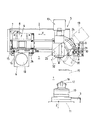
このNC工作機械は,例えば,ベッド1上にZ軸方向に往復移動可能に配設されたZ軸スライド3,Z軸スライド3に設置された主軸10を回転自在に支持する主軸台11,及びZ軸テーブル3に対してベッド1上で独立して設けられ且つZ軸スライド3が往復移動するZ軸方向に直交するX軸方向に移動可能なX軸スライド2を有している。Z軸スライド3は,ベッド1上でサーボモータ等のモータでZ軸方向に往復移動するように構成されている。また,主軸台11に回転自在に支持された主軸10は,例えば,スピンドルモータによって回転駆動される。主軸10の先端には,ワーク19を把持するチャック12が設けられている。ワーク19は,チャック12に把持されて主軸10の回転駆動によって回転させられる。また,X軸スライド2は,Z軸テーブル3のZ軸方向に直交するX軸方向に移動可能であり,主軸10のチャック12に取り付けられたワーク19と対向するようにベッド1上に配置されている。X軸スライド2は,ベッド1上でサーボモータ等のモータでX軸方向に往復移動するように構成されている。
Embodiments of an NC machine tool according to the present invention will be described below with reference to the drawings. This NC machine tool is particularly preferable when applied to a grinding machine having a lathe as a basic form, but is not limited to this and can be applied to various types of processing machines.
The NC machine tool includes, for example, a
このNC工作機械は,X軸スライド2には,2種類の刃物台,即ち,水平ユニット5と,水平ユニット5に隔置して位置したY軸ユニット4とが載置されている。水平ユニットとY軸ユニット4には,研削スピンドル13が組み込まれ,工具の回転駆動を行うように構成されている。また,Y軸ユニット4に設けたホルダベース15,16には,垂直軸状態又は斜軸状態のいずれかに姿勢変更可能な工具ユニット6が装着されている。Y軸ユニット4に工具ユニット6を斜軸の姿勢に装着した場合に,工具ユニット6に装着されたコレット工具14に軸付き砥石32として円筒型砥石18をセットすると,特に,小径のワーク19を加工するのに適している。工具ユニット6は,Y軸ユニット4に対してホルダベース15,16を介して2種類の状態即ち姿勢に取り付けることができる。このNC工作機械では,Y軸ユニット4に工具ユニット6を垂直軸状態の姿勢に装着する場合には,Y軸ユニット4のホルダベース15,16がX軸方向に平行になるようにX軸スライド2に設定する。また,Y軸ユニット4に工具ユニット6を斜軸状態の姿勢に装着する場合には,Y軸ユニット4のホルダベース15,16をX軸方向に直交してX軸スライド2に設定するものである。
In this NC machine tool, two types of tool rests, that is, a
このNC工作機械は,工具ユニット6に対するY軸ユニット4におけるホルダベース15,16の方向を変更するため,Y軸ユニット4には,X軸スライド2に固定されたベースプレート7に対して旋回可能な旋回プレート8に取り付けられている。工具ユニット6のX軸スライド2上での設置方向を変更するには,旋回プレート8をベースプレート7上で水平方向において90°回転させることによって,Y軸ユニット4の向き,言い換えれば,ホルダベース15,16の位置を変更できるものである。このNC工作機械には,ベースプレート15,16上で旋回プレート8をスムーズに旋回させるため,旋回プレート8をガイドするアジャストプレート26が設けられている。
Since this NC machine tool changes the direction of the holder bases 15, 16 in the Y-axis unit 4 with respect to the
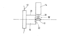
また,このNC工作機械では,ホルダベース15はY軸ユニット4に取り付けられており,ホルダベース16は工具ユニット6に取り付けられている。ホルダベース15とホルダベース16とは,Y軸ユニット4にボルト28によって固定されている。このNC工作機械は,工具ユニット6をY軸ユニット4に対して垂直軸状態から斜軸状態に姿勢変更して装着する場合の一例を説明すると,まず,工具ユニット6をホルダベース16に固定しているボルト(図示せず)を緩め,工具ユニット6をホルダベース16上でガイド溝27に沿って予め決められた所定量,実施例では,ホルダベース16の下端31まで下降させ,そこで,緩めた上記ボルトを緊締して工具ユニット6をホルダベース16に固定し,次いで,ボルト28を緩めてホルダベース16をホルダベース15に対して予め決められた所定量,実施例では,45°だけ傾斜させ,そこで,ホルダベース16をボルト28によってホルダベース15とY軸ユニット4とに固定し,それによって,工具ユニット6をY軸ユニット4に対して斜軸状態に設定して固定できるように構成されている。Y軸ユニット4では,工具ユニット6の取付け位置を垂直軸状態に比較して斜軸状態の場合に,ホルダベース16を下降させることによって,ワーク19に対する工具の位置を同一高さに設定できるようになる。
In this NC machine tool, the
また,このNC工作機械では,工具ユニット6を垂直軸状態に設定した時には,軸付き砥石としてそろばん型砥石17をセットしたコレット工具14を工具ユニット6に装着し,図6及び図7に示すように,ワーク19の端面20を大きい径の球面又は非球面22に加工するのに適用してワーク19を高精度に加工できるものである。また,工具ユニット6をY軸ユニット4に対して斜軸状態に設定した時には,軸付き砥石として円筒型砥石18をセットしたコレット工具14を工具ユニット6に装着し,図8及び図9に示すように,ワーク19の端面20に小さい径の球面23を加工するのに適用する。この実施例では,工具ユニット6に装着したコレット工具14は,軸付き砥石32を取り付ける例を示したが,軸付き研削工具即ちバイトを取り付けてもよいことは勿論である。
Further, in this NC machine tool, when the
また,水平ユニット5は,X軸スライド2に固定したベース24に取付け角度を変更可能に取り付けられる工具ホルダ部25を備えている。水平ユニット5は,X軸スライド2に固定されたベース24に対して水平方向を変更できるホルダ9を備えており,ホルダ9には,軸付き砥石32等の工具を取り付けるための工具ホルダ部25が一体構造に設けられている。この実施例では,工具ホルダ部25には軸付き砥石32等の各種の砥石が取り付けられるが,バイト等の別の工具を取り付けることができることは勿論である。ホルダ9には,円弧状の一対のガイド溝29が形成されている。水平ユニット5の水平方向における向き即ち方向を変更するには,ボルト30を緩め,ホルダ9をベース24に対してガイド溝29に沿って予め決められた所定の角度(図では45°)だけ回転させ,次いで,ボルト30をねじ込んでホルダ9をベース24に固定することによって達成できる。
Further, the
また,このNC工作機械は,水平ユニット5に装着される軸付き砥石32は,図10に示すように,ワーク19の外径即ち外周面である側面21及び端面20を研削加工することができ,また,ワーク19が内径を有するものであれば,内径を研削加工できることは勿論である。また,Y軸ユニット4に装着されたコレット工具14にセットした軸付き砥石32は,図6〜図9に示すように,ワーク19の端面20における球面又は非球面を研削加工するのに適用して好ましいものである。
Further, in this NC machine tool, the shaft-mounted
このNC工作機械は,上記のように構成されているので,合成樹脂材,高硬度脆性材,セラミック等の各種のワーク19に対する加工箇所,例えば,各種の端面20を球面や非球面に加工したり,外径や内径等を加工したり,或いは,ワーク19の素材を切削で粗加工したり,粗砥石で中仕上げ加工したり,或いは仕上げ砥石で研削仕上げ加工をしたり,磨き工具で研磨加工をしたり,このような加工状態に対応して,各種の砥石を取り付けた軸付き砥石32を加工目的に従って選定し,選定した軸付き砥石32をコレット工具14に取り付け,垂直軸又は斜軸のいずれかの取付け角に変更即ち姿勢を変更して,ワーク19をチャック12で把持状態を変更することなく,一連の切削加工や研磨加工を同時即ち並行して高精度に迅速に達成できるものである。
Since this NC machine tool is configured as described above, machining points for
このNC工作機械は,例えば,ワークをバイト,砥石等の工具で切削加工するNC旋盤等の工作機械に適用して好ましいものである。 This NC machine tool is preferably applied to a machine tool such as an NC lathe for cutting a workpiece with a tool such as a cutting tool or a grindstone.
2 X軸スライド
4 Y軸ユニット
5 水平ユニット
6 工具ユニット
7 ベースプレート
8 旋回プレート
9 ホルダ
10 主軸
11 主軸台
12 チャック
13 研削スピンドル
14 コレット工具
15,16 ホルダベース
17 そろばん型砥石
18 円筒型砥石
19 ワーク
20 ワーク端面
21 ワーク側面(外径)
24 ベース
25 工具ホルダ部
26 アジャストプレート
32 軸付き砥石
2 X-axis slide 4 Y-
24
Claims (5)
前記X軸スライドには,水平ユニットと該水平ユニットに隔置して位置するY軸ユニットが載置され,前記水平ユニットと前記Y軸ユニットには研削スピンドルが設けられ,前記Y軸ユニットに設けたホルダベースには,垂直軸状態又は斜軸状態のいずれかに変更可能な工具ユニットが装着され,前記工具ユニットを前記Y軸ユニットに前記垂直軸状態に装着することによって前記Y軸ユニットの前記ホルダベースを前記X軸方向に平行に前記X軸スライドに設定することができ,前記工具ユニットを前記Y軸ユニットに前記斜軸状態に装着することによって前記Y軸ユニットの前記ホルダベースを前記X軸方向に直交して前記X軸スライドに設定することができ,
前記水平ユニットは,前記X軸スライドに固定したベースに取付け角度を変更可能に取り付けられるホルダを備えており,前記ホルダは軸付き砥石を保持する工具ホルダ部が一体構造に構成されており,
前記チャックによる前記ワークの再チャッキングを行うことなく,前記水平ユニットの前記工具ホルダ部に装着された前記軸付き砥石によって前記ワークの外径及び端面を研削加工することができ,また,前記Y軸ユニットの前記工具ユニットに取り付けられたコレット工具に装着された軸付き砥石によって前記ワークの前記端面における球面又は非球面を研削加工することができることを特徴とするNC工作機械。 An NC machine tool comprising: a spindle that is rotatably arranged on the spindle stock and has a chuck for gripping a workpiece; and an X-axis slide that is movable in the X-axis direction perpendicular to the Z-axis direction in which the spindle moves. In
The X-axis slide is mounted with a horizontal unit and a Y-axis unit positioned so as to be spaced apart from the horizontal unit. The horizontal unit and the Y-axis unit are provided with a grinding spindle, and are provided in the Y-axis unit. The holder base is mounted with a tool unit that can be changed to either the vertical axis state or the oblique axis state, and the tool unit is mounted on the Y axis unit in the vertical axis state to thereby change the Y axis unit. A holder base can be set on the X-axis slide in parallel with the X-axis direction, and the holder base of the Y-axis unit is attached to the X-axis by attaching the tool unit to the Y-axis unit in the oblique axis state. Can be set to the X-axis slide perpendicular to the axial direction ,
The horizontal unit includes a holder that can be attached to a base fixed to the X-axis slide so that the mounting angle can be changed. The holder includes a tool holder portion that holds a grindstone with a shaft, and is configured as an integral structure.
Without re-chucking the workpiece by the chuck, the outer diameter and end face of the workpiece can be ground by the grindstone with a shaft mounted on the tool holder portion of the horizontal unit, and the Y An NC machine tool , wherein a spherical surface or an aspherical surface of the end surface of the workpiece can be ground by a grindstone with a shaft attached to a collet tool attached to the tool unit of the shaft unit .
Priority Applications (1)
| Application Number | Priority Date | Filing Date | Title |
|---|---|---|---|
| JP2006084408A JP4712586B2 (en) | 2006-03-27 | 2006-03-27 | NC machine tool |
Applications Claiming Priority (1)
| Application Number | Priority Date | Filing Date | Title |
|---|---|---|---|
| JP2006084408A JP4712586B2 (en) | 2006-03-27 | 2006-03-27 | NC machine tool |
Publications (2)
| Publication Number | Publication Date |
|---|---|
| JP2007253306A JP2007253306A (en) | 2007-10-04 |
| JP4712586B2 true JP4712586B2 (en) | 2011-06-29 |
Family
ID=38628042
Family Applications (1)
| Application Number | Title | Priority Date | Filing Date |
|---|---|---|---|
| JP2006084408A Active JP4712586B2 (en) | 2006-03-27 | 2006-03-27 | NC machine tool |
Country Status (1)
| Country | Link |
|---|---|
| JP (1) | JP4712586B2 (en) |
Families Citing this family (4)
| Publication number | Priority date | Publication date | Assignee | Title |
|---|---|---|---|---|
| TWI427447B (en) * | 2007-11-16 | 2014-02-21 | Hon Hai Prec Ind Co Ltd | System and method for slanted aspherical lens machining |
| JP5330219B2 (en) * | 2009-12-28 | 2013-10-30 | 西部電機株式会社 | Multifunctional in-machine measuring device for processing machine |
| CN102632435B (en) * | 2012-05-11 | 2013-12-25 | 中国工程物理研究院机械制造工艺研究所 | Double-flexible-grinding-head magnetorheological polishing device |
| CN103506955B (en) * | 2013-09-12 | 2016-08-17 | 上海交通大学 | Internal Spherical Surface ring accurate grinding is at level detecting apparatus and automatic testing method |
Citations (4)
| Publication number | Priority date | Publication date | Assignee | Title |
|---|---|---|---|---|
| JPS4898497A (en) * | 1972-03-27 | 1973-12-14 | ||
| JPS5753867A (en) * | 1980-09-13 | 1982-03-31 | Pioneer Electronic Corp | Bookshelf type record player |
| JP2003011057A (en) * | 2001-07-02 | 2003-01-15 | Toshiba Mach Co Ltd | Nc machine tool having turning shaft |
| JP2004148454A (en) * | 2002-10-31 | 2004-05-27 | Japan Science & Technology Agency | Method and device for grinding forming die of micro lens array |
Family Cites Families (1)
| Publication number | Priority date | Publication date | Assignee | Title |
|---|---|---|---|---|
| JPS5753867U (en) * | 1980-09-11 | 1982-03-29 |
-
2006
- 2006-03-27 JP JP2006084408A patent/JP4712586B2/en active Active
Patent Citations (4)
| Publication number | Priority date | Publication date | Assignee | Title |
|---|---|---|---|---|
| JPS4898497A (en) * | 1972-03-27 | 1973-12-14 | ||
| JPS5753867A (en) * | 1980-09-13 | 1982-03-31 | Pioneer Electronic Corp | Bookshelf type record player |
| JP2003011057A (en) * | 2001-07-02 | 2003-01-15 | Toshiba Mach Co Ltd | Nc machine tool having turning shaft |
| JP2004148454A (en) * | 2002-10-31 | 2004-05-27 | Japan Science & Technology Agency | Method and device for grinding forming die of micro lens array |
Also Published As
| Publication number | Publication date |
|---|---|
| JP2007253306A (en) | 2007-10-04 |
Similar Documents
| Publication | Publication Date | Title |
|---|---|---|
| JP4837448B2 (en) | Precision roll lathe | |
| JP4777149B2 (en) | Roll processing method | |
| US8827611B2 (en) | Free form cutting machine | |
| US7785173B2 (en) | Superfinishing machine and method | |
| JP4953599B2 (en) | Grinding method and grinding apparatus for workpiece profile | |
| JP2006312233A (en) | Device and method for processing optical workpiece, particularly, plastic spectacle lens | |
| JP2006297520A (en) | Multi-axis spherical grinding device and grinding method | |
| JP2002103139A (en) | Gear grinding method, turret head for gear grinding, and gear grinding tool | |
| JP2020069550A (en) | Work-piece processing system and work-piece processing method | |
| JP4712586B2 (en) | NC machine tool | |
| JP5239251B2 (en) | Traverse grinding apparatus and processing method | |
| JP2006320970A (en) | Machining device | |
| JP2011224668A (en) | Lens grinding method equipped with grinding wheel automatic exchanging device, and lens grinding device thereof | |
| JP2010029947A (en) | Compound end mill and processing method using compound end mill | |
| TWI597114B (en) | Horizontal turning machine for milling machines (1) | |
| JPH08318456A (en) | Spindle tapered hole re-boring device | |
| JP2004249438A (en) | Vertical type cylinder grinding machine and grinding method using the same | |
| JP2001353645A (en) | Cutting edge forming method and grinding machining device of machining tool | |
| JP2005028556A (en) | Machining method of free curved surface | |
| JPH1190799A (en) | Machine tool for crank pin machining and machining method for crank pin | |
| JP2004188557A (en) | Lens machining device | |
| JP6565380B2 (en) | Cutting device, cutting method and annular tool | |
| JP2020082278A (en) | Machine tool and cutting method | |
| EP0128779A2 (en) | Spherical surface grinding device | |
| CN211992263U (en) | Numerical control multifunctional screw tap groove grinding machine |
Legal Events
| Date | Code | Title | Description |
|---|---|---|---|
| A621 | Written request for application examination |
Free format text: JAPANESE INTERMEDIATE CODE: A621 Effective date: 20080501 |
|
| A977 | Report on retrieval |
Free format text: JAPANESE INTERMEDIATE CODE: A971007 Effective date: 20100702 |
|
| A131 | Notification of reasons for refusal |
Free format text: JAPANESE INTERMEDIATE CODE: A131 Effective date: 20100727 |
|
| A521 | Request for written amendment filed |
Free format text: JAPANESE INTERMEDIATE CODE: A523 Effective date: 20100917 |
|
| TRDD | Decision of grant or rejection written | ||
| A01 | Written decision to grant a patent or to grant a registration (utility model) |
Free format text: JAPANESE INTERMEDIATE CODE: A01 Effective date: 20110315 |
|
| A61 | First payment of annual fees (during grant procedure) |
Free format text: JAPANESE INTERMEDIATE CODE: A61 Effective date: 20110323 |
|
| R150 | Certificate of patent or registration of utility model |
Ref document number: 4712586 Country of ref document: JP Free format text: JAPANESE INTERMEDIATE CODE: R150 |
|
| R250 | Receipt of annual fees |
Free format text: JAPANESE INTERMEDIATE CODE: R250 |
|
| R250 | Receipt of annual fees |
Free format text: JAPANESE INTERMEDIATE CODE: R250 |
|
| R250 | Receipt of annual fees |
Free format text: JAPANESE INTERMEDIATE CODE: R250 |
|
| R250 | Receipt of annual fees |
Free format text: JAPANESE INTERMEDIATE CODE: R250 |