JP4709518B2 - Proton conducting membrane and fuel cell - Google Patents
Proton conducting membrane and fuel cell Download PDFInfo
- Publication number
- JP4709518B2 JP4709518B2 JP2004285467A JP2004285467A JP4709518B2 JP 4709518 B2 JP4709518 B2 JP 4709518B2 JP 2004285467 A JP2004285467 A JP 2004285467A JP 2004285467 A JP2004285467 A JP 2004285467A JP 4709518 B2 JP4709518 B2 JP 4709518B2
- Authority
- JP
- Japan
- Prior art keywords
- proton
- membrane
- fuel cell
- methanol
- anode
- Prior art date
- Legal status (The legal status is an assumption and is not a legal conclusion. Google has not performed a legal analysis and makes no representation as to the accuracy of the status listed.)
- Expired - Fee Related
Links
- 0 C*C(C)(CC1(c2c3)c4cc(O)c(C)cc4C(*)(*)C1)c2cc(-c1ccc(C(CCC(C)C2)C2C2=O)c2c1)c3O Chemical compound C*C(C)(CC1(c2c3)c4cc(O)c(C)cc4C(*)(*)C1)c2cc(-c1ccc(C(CCC(C)C2)C2C2=O)c2c1)c3O 0.000 description 1
Images

Classifications
-
- C—CHEMISTRY; METALLURGY
- C08—ORGANIC MACROMOLECULAR COMPOUNDS; THEIR PREPARATION OR CHEMICAL WORKING-UP; COMPOSITIONS BASED THEREON
- C08J—WORKING-UP; GENERAL PROCESSES OF COMPOUNDING; AFTER-TREATMENT NOT COVERED BY SUBCLASSES C08B, C08C, C08F, C08G or C08H
- C08J5/00—Manufacture of articles or shaped materials containing macromolecular substances
- C08J5/20—Manufacture of shaped structures of ion-exchange resins
- C08J5/22—Films, membranes or diaphragms
- C08J5/2206—Films, membranes or diaphragms based on organic and/or inorganic macromolecular compounds
- C08J5/2218—Synthetic macromolecular compounds
- C08J5/2256—Synthetic macromolecular compounds based on macromolecular compounds obtained by reactions other than those involving carbon-to-carbon bonds, e.g. obtained by polycondensation
-
- H—ELECTRICITY
- H01—ELECTRIC ELEMENTS
- H01M—PROCESSES OR MEANS, e.g. BATTERIES, FOR THE DIRECT CONVERSION OF CHEMICAL ENERGY INTO ELECTRICAL ENERGY
- H01M8/00—Fuel cells; Manufacture thereof
- H01M8/10—Fuel cells with solid electrolytes
- H01M8/1009—Fuel cells with solid electrolytes with one of the reactants being liquid, solid or liquid-charged
- H01M8/1011—Direct alcohol fuel cells [DAFC], e.g. direct methanol fuel cells [DMFC]
-
- H—ELECTRICITY
- H01—ELECTRIC ELEMENTS
- H01M—PROCESSES OR MEANS, e.g. BATTERIES, FOR THE DIRECT CONVERSION OF CHEMICAL ENERGY INTO ELECTRICAL ENERGY
- H01M8/00—Fuel cells; Manufacture thereof
- H01M8/10—Fuel cells with solid electrolytes
- H01M8/1016—Fuel cells with solid electrolytes characterised by the electrolyte material
- H01M8/1018—Polymeric electrolyte materials
- H01M8/102—Polymeric electrolyte materials characterised by the chemical structure of the main chain of the ion-conducting polymer
- H01M8/1023—Polymeric electrolyte materials characterised by the chemical structure of the main chain of the ion-conducting polymer having only carbon, e.g. polyarylenes, polystyrenes or polybutadiene-styrenes
-
- C—CHEMISTRY; METALLURGY
- C08—ORGANIC MACROMOLECULAR COMPOUNDS; THEIR PREPARATION OR CHEMICAL WORKING-UP; COMPOSITIONS BASED THEREON
- C08J—WORKING-UP; GENERAL PROCESSES OF COMPOUNDING; AFTER-TREATMENT NOT COVERED BY SUBCLASSES C08B, C08C, C08F, C08G or C08H
- C08J2365/00—Characterised by the use of macromolecular compounds obtained by reactions forming a carbon-to-carbon link in the main chain; Derivatives of such polymers
-
- H—ELECTRICITY
- H01—ELECTRIC ELEMENTS
- H01M—PROCESSES OR MEANS, e.g. BATTERIES, FOR THE DIRECT CONVERSION OF CHEMICAL ENERGY INTO ELECTRICAL ENERGY
- H01M2300/00—Electrolytes
- H01M2300/0017—Non-aqueous electrolytes
- H01M2300/0065—Solid electrolytes
- H01M2300/0082—Organic polymers
-
- Y—GENERAL TAGGING OF NEW TECHNOLOGICAL DEVELOPMENTS; GENERAL TAGGING OF CROSS-SECTIONAL TECHNOLOGIES SPANNING OVER SEVERAL SECTIONS OF THE IPC; TECHNICAL SUBJECTS COVERED BY FORMER USPC CROSS-REFERENCE ART COLLECTIONS [XRACs] AND DIGESTS
- Y02—TECHNOLOGIES OR APPLICATIONS FOR MITIGATION OR ADAPTATION AGAINST CLIMATE CHANGE
- Y02E—REDUCTION OF GREENHOUSE GAS [GHG] EMISSIONS, RELATED TO ENERGY GENERATION, TRANSMISSION OR DISTRIBUTION
- Y02E60/00—Enabling technologies; Technologies with a potential or indirect contribution to GHG emissions mitigation
- Y02E60/30—Hydrogen technology
- Y02E60/50—Fuel cells
-
- Y—GENERAL TAGGING OF NEW TECHNOLOGICAL DEVELOPMENTS; GENERAL TAGGING OF CROSS-SECTIONAL TECHNOLOGIES SPANNING OVER SEVERAL SECTIONS OF THE IPC; TECHNICAL SUBJECTS COVERED BY FORMER USPC CROSS-REFERENCE ART COLLECTIONS [XRACs] AND DIGESTS
- Y10—TECHNICAL SUBJECTS COVERED BY FORMER USPC
- Y10T—TECHNICAL SUBJECTS COVERED BY FORMER US CLASSIFICATION
- Y10T428/00—Stock material or miscellaneous articles
- Y10T428/249921—Web or sheet containing structurally defined element or component
- Y10T428/249953—Composite having voids in a component [e.g., porous, cellular, etc.]
- Y10T428/249976—Voids specified as closed
- Y10T428/249977—Specified thickness of void-containing component [absolute or relative], numerical cell dimension or density
Landscapes
- Chemical & Material Sciences (AREA)
- Manufacturing & Machinery (AREA)
- Engineering & Computer Science (AREA)
- Chemical Kinetics & Catalysis (AREA)
- Electrochemistry (AREA)
- General Chemical & Material Sciences (AREA)
- Sustainable Energy (AREA)
- Life Sciences & Earth Sciences (AREA)
- Sustainable Development (AREA)
- Materials Engineering (AREA)
- Inorganic Chemistry (AREA)
- Crystallography & Structural Chemistry (AREA)
- Health & Medical Sciences (AREA)
- Medicinal Chemistry (AREA)
- Polymers & Plastics (AREA)
- Organic Chemistry (AREA)
- Fuel Cell (AREA)
- Conductive Materials (AREA)
- Polyoxymethylene Polymers And Polymers With Carbon-To-Carbon Bonds (AREA)
Description
本発明は、燃料電池やアルカリ電気分解工業に好適に使用され得るプロトン伝導性ポリマーと、このプロトン伝導性ポリマーを含む電解質膜を備えた燃料電池に関するものである。 The present invention relates to a proton conductive polymer that can be suitably used in the fuel cell and the alkaline electrolysis industry, and a fuel cell including an electrolyte membrane containing the proton conductive polymer.
燃料電池は、水素と酸素を使用して電気化学反応で発電するため、クリーンな発電装置として注目されている。この燃料電池としては、水素ガスを燃料とする固体高分子電解質型燃料電池が従来から良く知られている。この固体高分子電解質型燃料電池に使用される固体高分子電解質膜が例えば特許文献1,2に開示されている。
Fuel cells are attracting attention as clean power generation devices because they generate electricity by electrochemical reaction using hydrogen and oxygen. As this fuel cell, a solid polymer electrolyte fuel cell using hydrogen gas as a fuel has been well known. For example,
特許文献1は、スルホアルキル基を側鎖に含む芳香族炭化水素系高分子化合物からなる固体高分子電解質膜を使用することにより、電解質膜の耐久性が向上され、固体高分子電解質型燃料電池の出力特性が改善されることを開示している。一方、特許文献2には、炭化フッ素系ビニルモノマーと炭化水素系ビニルモノマーとの共重合体で形成された主鎖とスルホン酸基を有する炭化水素系側鎖とから構成されている固体高分子電解質膜において、炭化水素系側鎖にαメチルスチレン基を含有させることにより、固体高分子電解質膜の酸化劣化を防止することが記載されている。
Patent Document 1 discloses that the durability of an electrolyte membrane is improved by using a solid polymer electrolyte membrane made of an aromatic hydrocarbon polymer compound having a sulfoalkyl group in the side chain, and a solid polymer electrolyte fuel cell is disclosed. It is disclosed that the output characteristics are improved. On the other hand,
ところで、メタノールを改質せずに直接燃料電池のアノードに供給する直接メタノール型燃料電池(DMFC)の研究が進められている。この直接メタノール型燃料電池では改質器が不要であるために電池の大幅な軽量・コンパクト化が可能であり、携帯型燃料電池としても期待されている。 By the way, research on a direct methanol fuel cell (DMFC) for supplying methanol directly to the anode of the fuel cell without reforming is in progress. Since this direct methanol fuel cell does not require a reformer, the battery can be significantly reduced in weight and size, and is expected as a portable fuel cell.
この直接メタノール型燃料電池のプロトン伝導膜としては、特許文献3に記載されているようなパーフルオロスルホン酸ポリマー膜が多用されている。しかしながら、このパーフルオロスルホン酸ポリマー膜は、メタノールクロスオーバ現象が大きく、そのうえプロトン伝導性においても改良の余地を残しているため、膜電極接合体(MEA)において十分な発電効率を得られていない。
本発明は、メタノールの透過を抑制する効果が高く、かつプロトン伝導性に優れたプロトン伝導膜と、このプロトン伝導膜を含む燃料電池とを提供することを目的とする。 The present invention aims at providing a high effect of suppressing the permeation of methanol, and a proton Den Shirubemaku having excellent proton conductivity, and a fuel cell including the proton Den Shirubemaku.
本発明に係る第1の態様によれば、芳香族性立体化合物単位とプロトン伝導性化合物単位から構成された下記化2−2で表される繰り返し単位からなるポリマーを含むことを特徴とするプロトン伝導膜が提供される。

本発明に係る第2の態様によれば、アノードと、
カソードと、
前記アノード及び前記カソードの間に配置され、第1の態様に係るプロトン伝導膜と
を具備することを特徴とする燃料電池が提供される。
According to a second aspect of the present invention, an anode;
A cathode,
There is provided a fuel cell comprising the proton conducting membrane according to the first aspect, which is disposed between the anode and the cathode.
本発明によれば、メタノールの透過を抑制する効果が高く、かつプロトン伝導性に優れたプロトン伝導膜と、このプロトン伝導膜を含む燃料電池とを提供することができる。
According to the present invention, it is possible to provide a high effect of suppressing the permeation of methanol, and a proton Den Shirubemaku having excellent proton conductivity, and a fuel cell including the proton Den Shirubemaku.
本発明者らは鋭意研究を重ねた結果、メタノール排除性化合物単位とプロトン伝導性化合物単位とを含有するプロトン伝導性ポリマーによると、メタノールの透過抑制とプロトン伝導性向上の双方を達成し得ることを見出し、本発明に至ったのである。 As a result of intensive studies, the inventors of the present invention can achieve both methanol permeation suppression and proton conductivity improvement according to a proton conductive polymer containing a methanol-exclusion compound unit and a proton conductive compound unit. And found the present invention.
すなわち、芳香族性立体化合物単位とプロトン伝導性化合物単位とを含むプロトン伝導性ポリマーは、パーフルオロアルキルスルホン酸に比較してメタノールとの親和性が低いため、メタノールの透過を抑制することができる。また、このプロトン伝導性ポリマーは、パーフルオロアルキルスルホン酸に比較してプロトン伝導性を向上することができる。さらに、このポリマーは、非フッ素系であるにも拘わらず、酸化分解と熱分解を生じ難く、化学的安定性にも優れている。 That is, a proton conductive polymer containing an aromatic steric compound unit and a proton conductive compound unit has a lower affinity for methanol than perfluoroalkylsulfonic acid, and therefore can inhibit methanol permeation. . Moreover, this proton conductive polymer can improve proton conductivity compared with perfluoroalkylsulfonic acid. Furthermore, although this polymer is non-fluorine-based, it does not easily undergo oxidative decomposition and thermal decomposition, and has excellent chemical stability.
従って、このプロトン伝導性ポリマーを含む電解質膜を備えた燃料電池によると、パーフルオロアルキルスルホン酸型膜を備えた燃料電池に比較して膜電極接合体(MEA)の反応効率を高めることが可能である。 Therefore, according to the fuel cell including the electrolyte membrane containing the proton conductive polymer, it is possible to increase the reaction efficiency of the membrane electrode assembly (MEA) as compared with the fuel cell including the perfluoroalkylsulfonic acid type membrane. It is.
以下、プロトン伝導性ポリマーについて詳しく説明する。 Hereinafter, the proton conductive polymer will be described in detail.
プロトン伝導性ポリマーは、下記化5で表される繰り返し単位を有することが望ましい。
但し、Xは芳香族性立体化合物単位で、Yはプロトン伝導性化合物単位で、P,Q,Rはそれぞれ正の整数である。 However, X is an aromatic steric compound unit, Y is a proton conductive compound unit, and P, Q, and R are positive integers.
(芳香族性立体化合物単位)
芳香族性立体化合物単位は、芳香族環及び脂肪族性環状化合物が一つの炭素を中心に化学結合した構造を基本骨格とすることが望ましい。これにより、メタノールの透過を抑制する効果を高めることが可能になる。
(Aromatic stereocompound unit)
The aromatic steric compound unit preferably has a basic skeleton having a structure in which an aromatic ring and an aliphatic cyclic compound are chemically bonded around one carbon. Thereby, it becomes possible to enhance the effect of suppressing the permeation of methanol.
(プロトン伝導性化合物単位)
プロトン伝導性化合物単位は、プロトン伝導性官能基が結合した芳香族性化合物から形成されていることが望ましい。このプロトン伝導性官能基は、スルホン酸基であることが好ましい。これにより高いプロトン伝導性を実現することができる。
(Proton conductive compound unit)
The proton conductive compound unit is preferably formed from an aromatic compound to which a proton conductive functional group is bonded. This proton conductive functional group is preferably a sulfonic acid group. Thereby, high proton conductivity can be realized.
上述した化5で表される繰り返し単位のうち、下記化6で表される繰り返し単位が好ましい。
但し、R1,R2,R3,R4は互いに同じでも異なっていても良く、それぞれ炭素数が1〜10の置換基で、P,Q及びMはそれぞれ正の整数である。 However, R1, R2, R3 and R4 may be the same as or different from each other, each is a substituent having 1 to 10 carbon atoms, and P, Q and M are each a positive integer.
上記化6で表された繰り返し単位を有するプロトン伝導性ポリマーによると、メタノールとの親和性が低く、かつイオン交換基密度が高いため、メタノール透過抑制とプロトン伝導性の向上の双方を満足することができる。さらに、このポリマーは、非フッ素系であるにも拘わらず、化学的安定性にも優れている。 According to the proton conductive polymer having a repeating unit represented by the chemical formula 6 above, both the methanol permeation suppression and the proton conductivity improvement are satisfied because the affinity with methanol is low and the ion exchange group density is high. Can do. Furthermore, this polymer is excellent in chemical stability even though it is non-fluorine-based.
置換基R1,R2,R3,R4の炭素数を上述した範囲に限定するのは、炭素数が多くなると、高分子特性のうちの一つである剛直性が増大するので、キャスト法や溶融法による膜成型が困難になるばかりか、引っ張り強度が弱くなる恐れがあるからである。 The reason why the number of carbon atoms of the substituents R1, R2, R3, and R4 is limited to the above-described range is that, as the number of carbon atoms increases, the rigidity, which is one of the polymer characteristics, increases. This is because not only is it difficult to form a film, but the tensile strength may be weakened.
メタノールの透過抑制効果を十分なものとするために、置換基R1,R2,R3,R4は、それぞれ炭素数が1〜10の炭化水素基、カルボキシル基、または炭素数が1〜10のエーテル基であることが望ましい。 In order to make the permeation suppression effect of methanol sufficient, the substituents R1, R2, R3, and R4 are each a hydrocarbon group having 1 to 10 carbon atoms, a carboxyl group, or an ether group having 1 to 10 carbon atoms. It is desirable that
上記化5または化6に示す構造式を有するポリマーにおいて、Pの好ましい範囲を1〜200とし、Qの好ましい範囲を1〜200とし、かつMの好ましい範囲を80〜30000とすることが望ましい。これにより、メタノール透過率が小さく、プロトン伝導性、化学的安定性及び機械的強度に優れたプロトン伝導膜を実現することができる。Pのさらに好ましい範囲とQのさらに好ましい範囲は、それぞれ、20〜120である。また、Mのさらに好ましい範囲は3000〜25000である。 In the polymer having the structural formula shown in Chemical Formula 5 or Chemical Formula 6, it is desirable that the preferable range of P is 1 to 200, the preferable range of Q is 1 to 200, and the preferable range of M is 80 to 30000. Thereby, it is possible to realize a proton conductive membrane having a low methanol permeability and excellent in proton conductivity, chemical stability and mechanical strength. A more preferable range of P and a more preferable range of Q are 20 to 120, respectively. Moreover, the more preferable range of M is 3000-25000.
プロトン伝導性ポリマーの好適な用途として、燃料電池用電解質膜、燃料電池用電極、アルカリ電気分解工業が挙げられる。燃料電池の一例としては、直接メタノール型燃料電池が挙げられる。直接メタノール型燃料電池は、アノード触媒層を含むアノードと、カソード触媒層を含むカソードと、アノード及びカソードの間に配置される固体電解質膜とを備えるものである。アノードに供給される液体燃料には、メタノールを含むものが使用される。一方、カソードに供給される酸化剤には、空気などが使用される。この直接メタノール型燃料電池の模式図を図1に示す。 Suitable applications of the proton conducting polymer include fuel cell electrolyte membranes, fuel cell electrodes, and alkaline electrolysis industry. An example of the fuel cell is a direct methanol fuel cell. The direct methanol fuel cell includes an anode including an anode catalyst layer, a cathode including a cathode catalyst layer, and a solid electrolyte membrane disposed between the anode and the cathode. As the liquid fuel supplied to the anode, one containing methanol is used. On the other hand, air or the like is used as the oxidant supplied to the cathode. A schematic diagram of this direct methanol fuel cell is shown in FIG.
直接メタノール型燃料電池は、アノード触媒層1と、カソード触媒層2と、アノード触媒層1とカソード触媒層2の間に配置される固体電解質膜3と、固体電解質膜3の反対側のアノード触媒層1表面に配置されたアノード拡散層4と、固体電解質膜3の反対側のカソード触媒層2表面に配置されたカソード拡散層5とを備える。これら5層積層物は、一般に膜電極接合体(MEA)6と呼ばれる。
The direct methanol fuel cell includes an anode catalyst layer 1, a
アノード触媒層1に含まれるアノード触媒としては、例えば、Pt−Ru合金のような白金合金が挙げられる。一方、カソード触媒層2に含まれるカソード触媒としては、例えば、Ptが挙げられる。アノード拡散層4は、アノード触媒層1に液体燃料を均一に拡散させるためのもので、例えばカーボンペーパから形成される。また、カソード拡散層5は、カソード触媒層2に酸化剤を均一に拡散させるためのもので、例えばカーボンペーパから形成される。固体電解質膜3には、本発明のプロトン伝導性ポリマーを含む電解質膜が使用される。
Examples of the anode catalyst included in the anode catalyst layer 1 include a platinum alloy such as a Pt—Ru alloy. On the other hand, examples of the cathode catalyst included in the
例えばメタノール水溶液からなる液体燃料は、アノード拡散層4を通してアノード触媒層1に供給される。また、空気のような酸化剤は、カソード拡散層5を通してカソード触媒層2に供給される。アノード触媒層1においては、下記(1)式に示す反応が生じる。
For example, a liquid fuel composed of an aqueous methanol solution is supplied to the anode catalyst layer 1 through the
CH3OH+H2O→CO2+6H++6e- (1)
生成したプロトンは固体電解質膜3を介してカソード触媒層2に供給される。また、電子は外部回路を通ってカソード触媒層2に供給される。これにより、カソード触媒層2において下記(2)式に示す反応、つまり発電反応が生じる。
CH 3 OH + H 2 O → CO 2 + 6H + + 6e − (1)
The generated protons are supplied to the
6H++3/2O2+6e-→3H2O (2)
なお、上記発電反応に伴って生成した二酸化炭素と水は、外部に排出される。また、アノード触媒層1で消費しきれなかった余剰のメタノールを回収して再び燃料として使用することが可能である。
6H + + 3 / 2O 2 + 6e − → 3H 2 O (2)
In addition, the carbon dioxide and water produced | generated with the said electric power generation reaction are discharged | emitted outside. Further, it is possible to recover excess methanol that could not be consumed by the anode catalyst layer 1 and use it again as fuel.
このような構成の燃料電池によれば、メタノールクロスオーバの発生を抑制することができ、電解質膜のプロトン伝導性を向上することができ、同時に発電反応を繰り返すことによる電解質膜の劣化を抑制することができるため、MEAの発電効率を高めることができる。 According to the fuel cell having such a configuration, generation of methanol crossover can be suppressed, proton conductivity of the electrolyte membrane can be improved, and deterioration of the electrolyte membrane due to repeated power generation reaction can be suppressed at the same time. Therefore, the power generation efficiency of the MEA can be increased.
[実施例]
以下、本発明の実施例を図面を参照して詳細に説明する。
[Example]
Hereinafter, embodiments of the present invention will be described in detail with reference to the drawings.
(実施例1)
<重合反応>
グローブボックス内をアルゴンガス雰囲気に置換し、その中で、テフロン(登録商標)攪拌子を100mL二口丸底フラスコに入れた。このフラスコ内において、3,3,3’,3’-テトラメチル-1,1’-スピロビスインダン-5,5’,6,6’-テトロール(分子量430)1.5g(3.5×10⁻³mol)をテトラクロロエチレン20mLに溶解させ、マグネチックスターラを施した。金属ナトリウム0.11gを溶液中に入れ、室温下で100rpmで1時間攪拌することによってナトリウムアルコラートを得た。2,7-ジクロロ-9-フルオレノン(分子量249)0.87g(3.5×10⁻³mol)を添加して4時間200rpmにて攪拌を行った。反応容器をグローブボックスから取り出し、中味を水100mL中に空けた。生成した沈殿物を100mL遠沈管2本に分け入れ、3000rpmで10分間遠心分離操作を行った。上澄み液を捨てさらに水50mLを入れ遠心分離を行う操作を3回繰り返した。アセトン50mLを用いて遠心分離を行った後、風乾、真空乾燥を経て高分子化合物を得た。
Example 1
<Polymerization reaction>
The inside of the glove box was replaced with an argon gas atmosphere, in which a Teflon (registered trademark) stirrer was placed in a 100 mL two-necked round bottom flask. In this flask, 1.5 g (3.5 × 3,3,3 ′, 3′-tetramethyl-1,1′-spirobisindane-5,5 ′, 6,6′-tetrol (molecular weight 430) 10 −3 mol) was dissolved in 20 mL of tetrachloroethylene and subjected to a magnetic stirrer. Sodium alcoholate was obtained by putting 0.11 g of sodium metal in the solution and stirring at 100 rpm for 1 hour at room temperature. 2,7-Dichloro-9-fluorenone (molecular weight 249) 0.87 g (3.5 × 10 −3 mol) was added and stirred at 200 rpm for 4 hours. The reaction vessel was removed from the glove box and the contents were emptied into 100 mL of water. The generated precipitate was divided into two 100 mL centrifuge tubes and centrifuged at 3000 rpm for 10 minutes. The operation of discarding the supernatant and adding 50 mL of water and centrifuging was repeated three times. Centrifugation was performed using 50 mL of acetone, and then a polymer compound was obtained through air drying and vacuum drying.
<スルホン化反応>
二口100mL丸底フラスコにリービッヒ冷却管、攪拌子、マグネチックスターラ及び氷浴を装着した。フラスコ内部に先に得られた重合物を入れ、ピリジン20mLを入れた。次いで、100rpmで15分間攪拌させた。発煙硫酸2mLをメスピペットを用いて内部に入れた。マグネチックスターラを用いて200rpmで2時間攪拌した。内容物をスポイトで取り、水100mL中に滴下した。生成した沈殿を100mL遠沈管2本に入れ3000rpmで20分間遠心分離を行った。その後上澄みを捨てさらに50mL×2本分の水で同様に遠心分離操作を行うことを3回繰り返した。最後にアセトン50mLで遠心分離し、風乾を行った。
<Sulfonation reaction>
A Liebig condenser, stir bar, magnetic stirrer, and ice bath were attached to a two-necked 100 mL round bottom flask. The polymer obtained previously was put in the flask, and 20 mL of pyridine was added. Subsequently, it was made to stir at 100 rpm for 15 minutes. 2 mL of fuming sulfuric acid was placed inside using a measuring pipette. The mixture was stirred at 200 rpm for 2 hours using a magnetic stirrer. The contents were taken with a dropper and dropped into 100 mL of water. The generated precipitate was put into two 100 mL centrifuge tubes and centrifuged at 3000 rpm for 20 minutes. Thereafter, the supernatant was discarded, and the same centrifugation operation was repeated 3 times with 50 mL × 2 water. Finally, it was centrifuged with 50 mL of acetone and air-dried.
<キャスト膜調製>
得られた樹脂をN,N,ジメチルホルムアミド30mLに溶解させ、ガラス板状にバーコータを用いて引き伸ばし、風乾後、真空乾燥を4時間施し、プロトン伝導膜であるキャストフィルムを得た。得られたキャストフィルムをピンセットで剥離し、0.02mol/lの塩酸に浸して保存した。
<Cast membrane preparation>
The obtained resin was dissolved in 30 mL of N, N, dimethylformamide, stretched into a glass plate using a bar coater, air-dried and then vacuum-dried for 4 hours to obtain a cast film as a proton conductive membrane. The obtained cast film was peeled off with tweezers and stored by being immersed in 0.02 mol / l hydrochloric acid.
実施例1のプロトン伝導膜に含まれる繰り返しユニットは、3,3,3’,3’-テトラメチル-1,1’-スピロビスインダン-6,6’-ジオール -9-フルオレノンスルホン酸である。繰り返しユニットの構造式を下記化7に示す。
(比較例)
プロトン伝導膜としてパーフルオロアルキルスルホン酸型膜(DuPont社製の商品名;Nafion112膜)を用意した。
(Comparative example)
A perfluoroalkylsulfonic acid type membrane (trade name manufactured by DuPont; Nafion 112 membrane) was prepared as a proton conductive membrane.
<メタノールクロスオーバ測定>
内径4cm、長さ5cmの円筒管の端を閉じることにより、開口部に幅2cmの淵を有し本体に内径6mmの穴を有するガラス管2本を準備した。2本のガラス管の間に比較例のプロトン伝導膜を挟み込み、片側の槽をA槽とし、もう一方の槽をB槽とした。A槽に3%メタノール水溶液を充填し、内径6mmの穴にシリコンゴムを詰め込んだ。B槽の穴にもシリコンゴムを詰め込み、その上から針付のゴム風船を突き刺しておいた。A,B槽を合わせたときをスタート0秒とする。20分ごとにB槽のゴム栓にマイクロシリンジを突き刺して内部のガスを20マイクロリットル採取し、ガスクロマトグラフに掛け、メタノールの濃度(ppm)を定量した。横軸に時間(分)を、縦軸にメタノール濃度(ppm)をプロットし、100分後のメタノール濃度を時間で除した値をメタノール拡散速度D0(ppm/分)とした。
<Methanol crossover measurement>
By closing the end of a cylindrical tube having an inner diameter of 4 cm and a length of 5 cm, two glass tubes having a ridge having a width of 2 cm at the opening and a hole having an inner diameter of 6 mm were prepared. The proton conductive membrane of the comparative example was sandwiched between two glass tubes, and the tank on one side was designated as A tank, and the other tank was designated as B tank. Tank A was filled with 3% aqueous methanol solution, and silicon rubber was packed into a hole with an inner diameter of 6 mm. Silicone rubber was also stuffed into the hole in tank B, and a rubber balloon with a needle was stuck through it. The time when tanks A and B are combined is 0 seconds from the start. Every 20 minutes, a microsyringe was inserted into the rubber stopper of the B tank, and 20 microliters of the internal gas was collected and applied to a gas chromatograph to quantify the methanol concentration (ppm). The time (min) is plotted on the horizontal axis and the methanol concentration (ppm) is plotted on the vertical axis, and the value obtained by dividing the methanol concentration after 100 minutes by time is defined as the methanol diffusion rate D0 (ppm / min).
同様な測定を実施例1のプロトン伝導膜を用いて測定し、そのときの拡散速度をD1とする。(D0/D1)からメタノールクロスオーバ抑制比を算出し、その結果を下記表1に示す。 A similar measurement is performed using the proton conductive membrane of Example 1, and the diffusion rate at that time is defined as D1. The methanol crossover suppression ratio was calculated from (D0 / D1), and the results are shown in Table 1 below.
<プロトン伝導性の測定>
以下の手順に従って電気伝導度測定用セルを作製した。
<Measurement of proton conductivity>
A cell for measuring electrical conductivity was prepared according to the following procedure.
(A)まず、白金電極を作製するためのセルを製造した。中央部に貫通した液だめ(縦0.5cm×横1.0cm×深さ1.0cm)を有するテフロン(登録商標)板(縦3.5cm×横4.5cm×高さ1.0cm)2枚を用意した。電極である白金箔(厚み0.30mm)を0.5cm×2.0cmにカットし、両面テープでテフロン(登録商標)板液だめの0.5cm辺と白金箔の0.5cmの辺が正確に一致するように貼り付けた。電極に液だめ側の端から0.7cmの位置に保護テープを貼り、電極面積が0.35cm2となるように調整した。 (A) First, a cell for producing a platinum electrode was manufactured. Teflon (registered trademark) plate (length: 3.5 cm × width: 4.5 cm × height: 1.0 cm) 2 having a reservoir (length 0.5 cm × width 1.0 cm × depth 1.0 cm) penetrating in the center 2 A sheet was prepared. Cut the electrode platinum foil (thickness 0.30mm) to 0.5cm x 2.0cm, and use double-sided tape to accurately place the 0.5cm side of the Teflon (registered trademark) plate reservoir and the 0.5cm side of the platinum foil. Pasted to match. A protective tape was applied to the electrode at a position 0.7 cm from the end on the liquid reservoir side, and the electrode area was adjusted to 0.35 cm 2 .
(B)次いで、白金黒のめっきを行った。白金電極の表面積を大きくするために、次の手順により白金電極表面に白金黒をめっきした。すなわち、1/40Nの塩酸30mLに、酢酸鉛(Pb(CH3COO)2・3H2O):0.008gと、塩化白金酸(H2PtCl6・6H2O):1gとを溶解させたものをめっき液とした。このめっき液中に上記(A)工程で作製した白金電極付テフロン(登録商標)板を1個ずつ浸し、浴電圧:3.0V、電流:14mA、電流密度:40mA/cm2となるように、直流電圧電流発生装置(アドバンテスト製R1644)をセットした。そして、2電極を交互に少しずつめっきするために、約1分ごとに装置側のプラス(+)とマイナス(−)の設定スイッチを入れ換えることにより電極のプラス(+)とマイナス(−)を交換する操作を50分間続けた。その後、2電極を蒸留水で洗浄し、10%希硫酸中において白金黒極板をマイナス極(−)に、また、別の新しい白金極板をプラス極(+)にして10分間3Vの電圧をかけることによりめっき液や吸着した塩素を除去した。最後に蒸留水で電極をよく洗浄し、蒸留水中に保存した。 (B) Next, platinum black plating was performed. In order to increase the surface area of the platinum electrode, platinum black was plated on the surface of the platinum electrode by the following procedure. That is, lead acetate (Pb (CH 3 COO) 2 .3H 2 O): 0.008 g and chloroplatinic acid (H 2 PtCl 6 .6H 2 O): 1 g were dissolved in 30 mL of 1 / 40N hydrochloric acid. The plating solution was used. The platinum electrode-attached Teflon (registered trademark) plates prepared in the step (A) are immersed one by one in this plating solution so that the bath voltage is 3.0 V, the current is 14 mA, and the current density is 40 mA / cm 2. A DC voltage / current generator (advantest R1644) was set. In order to plate the two electrodes alternately little by little, the plus (+) and minus (-) of the electrode can be changed by switching the plus (+) and minus (-) setting switches on the device side about every minute. The exchange operation was continued for 50 minutes. Thereafter, the two electrodes were washed with distilled water, and the platinum black electrode plate in 10% dilute sulfuric acid was set to the negative electrode (-), and another new platinum electrode plate was set to the positive electrode (+), and the voltage was 3 V for 10 minutes. Was applied to remove the plating solution and adsorbed chlorine. Finally, the electrode was thoroughly washed with distilled water and stored in distilled water.
(C)次いで、交流法(コール・コールプロット)による電気伝導度の測定を行った。比較例のプロトン伝導膜を、前述したA,B工程で作製したセルの液だめと白金黒電極を覆う大きさ、すなわち15mm×12mmの大きさにカットした後、2枚のテフロン(登録商標)(登録商標)板の間に挟んだ。次いで、プロトン伝導膜の両側の液だめに0.03N塩酸を約0.3mL入れて塩酸が伝導膜の両側から伝導膜全体を覆うようにした。セルをスタンドに固定し、白金黒電極をソーラトロン−インピーダンス/ゲイン−フェイスアナライザーSI1260に接続し、交流電流を高周波側から低周波側へ電流の周波数を小さくしながら比較例のプロトン伝導膜に流した。この時の抵抗値を実数軸および虚数軸に対してプロットした(コール・コールプロット)。一般的にグラフはこの場合、高周波側で半円を描いた後、低周波側では右上がりの直線の形となる。この半円の直径がサンプルの抵抗を表わしている。本測定においては、この半円の半径を見積り、その値から再生ナフィオン(Nafion)膜−H型の電気伝導度を計算した。 (C) Next, the electrical conductivity was measured by the alternating current method (Cole-Cole plot). The proton conductive membrane of the comparative example was cut into a size covering the liquid reservoir and platinum black electrode of the cell prepared in the above-described A and B steps, that is, 15 mm × 12 mm, and then two pieces of Teflon (registered trademark). (Registered trademark) sandwiched between plates. Next, about 0.3 mL of 0.03N hydrochloric acid was placed in the reservoirs on both sides of the proton conducting membrane so that the hydrochloric acid covered the entire conducting membrane from both sides of the conducting membrane. The cell was fixed to a stand, a platinum black electrode was connected to a Solartron-impedance / gain-face analyzer SI1260, and an alternating current was passed through the proton conducting membrane of the comparative example while decreasing the frequency of the current from the high frequency side to the low frequency side. . The resistance value at this time was plotted with respect to the real axis and the imaginary axis (Cole-Cole plot). In general, in this case, the graph is a straight line that rises to the right on the low frequency side after drawing a semicircle on the high frequency side. The diameter of this semicircle represents the resistance of the sample. In this measurement, the radius of this semicircle was estimated, and the electric conductivity of the regenerated Nafion film-H type was calculated from the value.
この測定によって膜抵抗を得た。膜中で電流が流れる距離はセルの構造上0.5cmである。従って、膜の電気伝導度は次の式(1)により求められる。 Membrane resistance was obtained by this measurement. The distance through which current flows in the film is 0.5 cm due to the cell structure. Therefore, the electrical conductivity of the film is obtained by the following equation (1).
X=D/(S×R) (1)
但し、Xはプロトン伝導度(W-1・cm-1)である。Dは電極間距離(cm)で、この場合、0.5(cm)である。Sは膜断面積(cm2)で、この場合、膜幅1.0(cm)と膜厚(cm)との積から算出される。Rは膜抵抗値(W)である。
X = D / (S × R) (1)
Where X is proton conductivity (W −1 · cm −1 ). D is the distance (cm) between the electrodes, and in this case, 0.5 (cm). S is a film cross-sectional area (cm 2 ). In this case, S is calculated from the product of the film width 1.0 (cm) and the film thickness (cm). R is the membrane resistance value (W).
上記(1)式より求めた比較例のプロトン伝導膜のプロトン伝導度をS0とした。実施例1のプロトン伝導膜について同様な測定を行ったときのプロトン伝導度をS1とした。(S1/S0)からプロトン伝導度相対比を算出し、その結果を下記表1に示す。 The proton conductivity of the proton conductive membrane of the comparative example obtained from the above equation (1) was S0. The proton conductivity when the same measurement was performed on the proton conducting membrane of Example 1 was defined as S1. The proton conductivity relative ratio was calculated from (S1 / S0), and the results are shown in Table 1 below.
<耐熱分解性の測定>
比較例1のプロトン伝導膜を10mg採取し、TG-DTA装置を用いて空気中の酸化分解温度を測定した。昇温速度は10℃/minで行った。そのときの酸化分解温度をT0(℃)とした。実施例1のプロトン伝導膜についても同様に測定を行い、そのときの酸化分解温度をT1とした。(T1/T0)から耐熱分解性相対比を算出し、その結果を下記表1に示す。
<Measurement of thermal decomposition resistance>
10 mg of the proton conducting membrane of Comparative Example 1 was sampled, and the oxidative decomposition temperature in air was measured using a TG-DTA apparatus. The heating rate was 10 ° C./min. The oxidative decomposition temperature at that time was T0 (° C.). The proton conducting membrane of Example 1 was similarly measured, and the oxidative decomposition temperature at that time was T1. The relative thermal decomposition resistance ratio was calculated from (T1 / T0), and the results are shown in Table 1 below.
<耐酸化分解性の測定>
100mlビーカをオイルバス中に固定し、過酸化水素水3%とFeSO4が40ppmから成る酸化性水溶液をビーカ内に入れた。オイルの温度を60℃に合わせた。比較例のプロトン伝導膜を3.0gカットし、重量を測定し、W0とした。膜のカットサンプルを先の酸化性溶液中に入れ、10時間静置した。その後サンプルを引き上げ、水洗、風乾、真空乾燥を施した後の重量をW1とし、W0とW1の差(W0−W1)から重量減量WFを算出した。実施例1の高分子電解質膜の重量減少量を同様にして算出し、WCを得た。(WF/WC)から実施例1の耐酸化分解性比を算出したところ、耐酸化分解性比(WF/WC)が1より大きくなり、実施例1の電解質膜における耐酸化分解性が比較例のフッ素系膜よりも大きいことがわかった。
<Measurement of oxidation and decomposition resistance>
A 100 ml beaker was fixed in an oil bath, and an oxidizing aqueous solution consisting of 3% hydrogen peroxide and 40 ppm FeSO 4 was placed in the beaker. The oil temperature was adjusted to 60 ° C. 3.0 g of the proton conductive membrane of the comparative example was cut, and the weight was measured to obtain W0. The cut sample of the membrane was put in the previous oxidizing solution and allowed to stand for 10 hours. Thereafter, the sample was pulled up, washed with water, air-dried, and vacuum-dried, and the weight loss WF was calculated from the difference between W0 and W1 (W0-W1). The weight reduction amount of the polymer electrolyte membrane of Example 1 was calculated in the same manner to obtain WC. When the oxidative decomposition resistance ratio of Example 1 was calculated from (WF / WC), the oxidative decomposition resistance ratio (WF / WC) was larger than 1, and the oxidative decomposition resistance of the electrolyte membrane of Example 1 was a comparative example. It was found to be larger than the fluorine-based film.
(実施例2)
実施例1の繰り返し構造単位に替わって3,3,3’,3’-テトラエチル-1,1’-スピロビスインダン-6,6’-ジオール -9-フルオレノンスルホン酸を有するプロトン伝導膜を調製し、実施例1と同様に膜物性の評価を行った。その結果を下記表1に示す。また、実施例2のプロトン伝導膜の繰り返しユニットの構造式を下記化8に示す。
Preparation of proton conducting membrane having 3,3,3 ′, 3′-tetraethyl-1,1′-spirobisindane-6,6′-diol-9-fluorenonesulfonic acid instead of the repeating structural unit of Example 1 Then, the film properties were evaluated in the same manner as in Example 1. The results are shown in Table 1 below. The structural formula of the repeating unit of the proton conducting membrane of Example 2 is shown in the following chemical formula 8.
(実施例3)
実施例1の繰り返し構造単位に替わって3,3,3’,3’-テトラプロピル-1,1’-スピロビスインダン-6,6’-ジオール -9-フルオレノンスルホン酸を有するプロトン伝導膜を調製し、実施例1と同様に膜物性の評価を行った。その結果を下記表1に示す。また、実施例3のプロトン伝導膜の繰り返しユニットの構造式を下記化9に示す。
A proton conducting membrane having 3,3,3 ′, 3′-tetrapropyl-1,1′-spirobisindane-6,6′-diol-9-fluorenonesulfonic acid instead of the repeating structural unit of Example 1 The film properties were evaluated in the same manner as in Example 1. The results are shown in Table 1 below. The structural formula of the repeating unit of the proton conducting membrane of Example 3 is shown in the following chemical formula 9.
(実施例4)
実施例1の繰り返し構造単位に替わって3,3,3’,3’-テトラ(メチルエチルエーテル) 1,1’-スピロビスインダン-6,6’-ジオール-9-フルオレノンスルホン酸を有するプロトン伝導膜を調製し、実施例1と同様に膜物性の評価を行った。その結果を下記表1に示す。また、実施例4のプロトン伝導膜の繰り返しユニットの構造式を下記化10に示す。
Proton with 3,3,3 ′, 3′-tetra (methyl ethyl ether) 1,1′-spirobisindane-6,6′-diol-9-fluorenonesulfonic acid instead of the repeating structural unit of Example 1 A conductive film was prepared, and film physical properties were evaluated in the same manner as in Example 1. The results are shown in Table 1 below. The structural formula of the repeating unit of the proton conducting membrane of Example 4 is shown in the following chemical formula 10.
(実施例5)
実施例1の繰り返し構造単位に替わって3,3,3’,3’-テトラカルボキシル-1,1’-スピロビスインダン-6,6’-ジオール -9-フルオレノンスルホン酸を有するプロトン伝導膜を調製し、実施例1と同様に膜物性の評価を行った。その結果を下記表1に示す。また、実施例5のプロトン伝導膜の繰り返しユニットの構造式を下記化11に示す。
(Example 5)
A proton conducting membrane having 3,3,3 ′, 3′-tetracarboxyl-1,1′-spirobisindane-6,6′-diol-9-fluorenonesulfonic acid instead of the repeating structural unit of Example 1 The film properties were evaluated in the same manner as in Example 1. The results are shown in Table 1 below. The structural formula of the repeating unit of the proton conducting membrane of Example 5 is shown in the following chemical formula 11.
なお、表2に、実施例1〜5の繰り返しユニットの重合数P,Q,Mを示す。
表1から明らかなように、実施例1〜5の非フッ素系プロトン伝導膜は、比較例のフッ素系プロトン伝導膜に比較してメタノールクロスオーバ抑制効果、プロトン伝導性、耐酸化分解性及び耐熱分解性に優れていることが理解できる。 As is apparent from Table 1, the non-fluorine proton conductive membranes of Examples 1 to 5 have a methanol crossover suppression effect, proton conductivity, oxidation-degradation resistance, and heat resistance as compared with the fluorine proton conductive membranes of the comparative examples. It can be understood that it is excellent in degradability.
次いで、実施例1〜5及び比較例のプロトン伝導膜を用いて直接メタノール型燃料電池を作製し、電流電圧特性を評価した。 Next, direct methanol fuel cells were fabricated using the proton conductive membranes of Examples 1 to 5 and the comparative example, and current-voltage characteristics were evaluated.
<単セルの組み立て>
炭素粉末からなる担体に白金-ルテニウムを担持させ、アノード触媒を調製した。アノード触媒を含むスラリーをカーボンペーパに塗布し、カーボンペーパ上にアノード触媒層を形成した(アノード側白金-ルテニウム担持量:2mg/cm2)。
<Assembly of single cell>
An anode catalyst was prepared by supporting platinum-ruthenium on a support made of carbon powder. A slurry containing an anode catalyst was applied to carbon paper, and an anode catalyst layer was formed on the carbon paper (anode-side platinum-ruthenium loading: 2 mg / cm 2 ).
一方、炭素粉末からなる担体に白金を担持させ、カソード触媒を調製した。カーボンペーパにカソード触媒を含むスラリーを塗布してカソード触媒層を形成した(カソード側白金担持:1mg/cm2)。 On the other hand, platinum was supported on a carrier made of carbon powder to prepare a cathode catalyst. A cathode catalyst layer was formed by applying a slurry containing a cathode catalyst to carbon paper (cathode side platinum support: 1 mg / cm 2 ).
実施例1〜5及び比較例のプロトン伝導膜それぞれから、プロトン伝導膜の一方の面にアノード触媒層を配置し、かつ他方の面にカソード触媒層を配置し、これらを熱圧着させることにより電極面積5cm2の膜電極(MEA)を作製した。 From each of the proton conducting membranes of Examples 1 to 5 and Comparative Example, an anode catalyst layer was disposed on one surface of the proton conducting membrane and a cathode catalyst layer was disposed on the other surface, and these were thermocompression bonded to form an electrode. A membrane electrode (MEA) having an area of 5 cm 2 was prepared.
得られた各膜電極をサーペンタイン流路を有する2枚のカーボン製セパレータで挟んだ後、さらにこれらを集電体2枚で挟み込んだ。これらをボルト締めし、評価用単セルとした。 Each obtained membrane electrode was sandwiched between two carbon separators having serpentine channels, and then these were sandwiched between two current collectors. These were bolted to form single cells for evaluation.
<単セル評価>
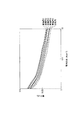
先の単セルを直接メタノール型燃料電池評価装置に装着した。3%のメタノール水溶液を液体燃料として2.5mL/minの流速で単セルのアノード側へ送液した。カソード側空気流量20mL/minで空気を供給した。単セル温度75℃における電流-電圧曲線を観察し、その結果を図2に示す。
<Single cell evaluation>
The previous single cell was directly attached to the methanol fuel cell evaluation apparatus. A 3% aqueous methanol solution was fed as liquid fuel to the anode side of the single cell at a flow rate of 2.5 mL / min. Air was supplied at a cathode side air flow rate of 20 mL / min. A current-voltage curve at a single cell temperature of 75 ° C. was observed, and the result is shown in FIG.
図2から明らかなように、実施例1〜5の化学構造を有するプロトン伝導膜を備えた燃料電池における電流-電圧特性が比較例に比べて高かった。これにより、本発明が直接メタノール型燃料電池の出力向上に効果を発揮していることがわかった。 As is clear from FIG. 2, the current-voltage characteristics in the fuel cell provided with the proton conducting membranes having the chemical structures of Examples 1 to 5 were higher than those in the comparative example. Thus, it was found that the present invention is effective in improving the output of the direct methanol fuel cell.
なお、本発明は上記実施形態そのままに限定されるものではなく、実施段階ではその要旨を逸脱しない範囲で構成要素を変形して具体化できる。また、上記実施形態に開示されている複数の構成要素の適宜な組み合わせにより、種々の発明を形成できる。例えば、実施形態に示される全構成要素から幾つかの構成要素を削除してもよい。さらに、異なる実施形態にわたる構成要素を適宜組み合わせてもよい。 Note that the present invention is not limited to the above-described embodiment as it is, and can be embodied by modifying the constituent elements without departing from the scope of the invention in the implementation stage. In addition, various inventions can be formed by appropriately combining a plurality of components disclosed in the embodiment. For example, some components may be deleted from all the components shown in the embodiment. Furthermore, constituent elements over different embodiments may be appropriately combined.
1…アノード触媒層、2…カソード触媒層、3…固体電解質膜、4…アノード拡散層、5…カソード拡散層、6…膜電極接合体(MEA)。 DESCRIPTION OF SYMBOLS 1 ... Anode catalyst layer, 2 ... Cathode catalyst layer, 3 ... Solid electrolyte membrane, 4 ... Anode diffusion layer, 5 ... Cathode diffusion layer, 6 ... Membrane electrode assembly (MEA).
Claims (3)
Wherein P is an integer selected inner shell of 20 to 120, wherein Q is an integer selected from among 20 to 120, according to claim 1 wherein M is characterized in that it is an integer selected from among 3000-25000 The proton conducting membrane as described.
カソードと、
前記アノード及び前記カソードの間に配置され、請求項1〜2いずれか1項記載のプロトン伝導膜と
を具備することを特徴とする燃料電池。 An anode,
A cathode,
A fuel cell comprising the proton conducting membrane according to claim 1 , which is disposed between the anode and the cathode.
Priority Applications (2)
| Application Number | Priority Date | Filing Date | Title |
|---|---|---|---|
| JP2004285467A JP4709518B2 (en) | 2004-09-29 | 2004-09-29 | Proton conducting membrane and fuel cell |
| US11/226,840 US7582376B2 (en) | 2004-09-29 | 2005-09-14 | Proton conductive polymer and fuel cell using the same |
Applications Claiming Priority (1)
| Application Number | Priority Date | Filing Date | Title |
|---|---|---|---|
| JP2004285467A JP4709518B2 (en) | 2004-09-29 | 2004-09-29 | Proton conducting membrane and fuel cell |
Publications (3)
| Publication Number | Publication Date |
|---|---|
| JP2006100144A JP2006100144A (en) | 2006-04-13 |
| JP2006100144A5 JP2006100144A5 (en) | 2007-11-01 |
| JP4709518B2 true JP4709518B2 (en) | 2011-06-22 |
Family
ID=36099573
Family Applications (1)
| Application Number | Title | Priority Date | Filing Date |
|---|---|---|---|
| JP2004285467A Expired - Fee Related JP4709518B2 (en) | 2004-09-29 | 2004-09-29 | Proton conducting membrane and fuel cell |
Country Status (2)
| Country | Link |
|---|---|
| US (1) | US7582376B2 (en) |
| JP (1) | JP4709518B2 (en) |
Families Citing this family (6)
| Publication number | Priority date | Publication date | Assignee | Title |
|---|---|---|---|---|
| JP4709518B2 (en) | 2004-09-29 | 2011-06-22 | 株式会社東芝 | Proton conducting membrane and fuel cell |
| EP2009724B1 (en) * | 2006-04-13 | 2011-10-26 | Sumitomo Chemical Company, Limited | Method for producing polymer electrolyte membrane, polymer electrolyte membrane and direct methanol fuel cell |
| US7718753B2 (en) * | 2007-06-13 | 2010-05-18 | Gm Global Technology Operations, Inc. | Organic superacids, polymers, derived from organic superacids, and methods of making and using the same |
| JP4444355B2 (en) * | 2008-09-03 | 2010-03-31 | 株式会社東芝 | Fuel cell |
| JP4691189B1 (en) * | 2009-11-25 | 2011-06-01 | 株式会社東芝 | Direct methanol fuel cell |
| EP3154690B1 (en) * | 2014-06-13 | 2019-06-26 | 3M Innovative Properties Company | Sulfonic acid-containing polymeric materials as amine sorbents |
Citations (3)
| Publication number | Priority date | Publication date | Assignee | Title |
|---|---|---|---|---|
| JP2002313366A (en) * | 2001-04-12 | 2002-10-25 | Ueda Seni Kagaku Shinkokai | Polymer electrolyte film, its manufacturing method, and fuel cell using polymer electrolyte film |
| JP2003031232A (en) * | 2001-05-08 | 2003-01-31 | Ube Ind Ltd | Polymer electrolyte for solid polymer fuel cell and fuel cell |
| US20030219640A1 (en) * | 2002-01-23 | 2003-11-27 | Polyfuel, Inc. | Acid-base proton conducting polymer blend membrane |
Family Cites Families (106)
| Publication number | Priority date | Publication date | Assignee | Title |
|---|---|---|---|---|
| US2762711A (en) * | 1953-04-29 | 1956-09-11 | Monsanto Chemicals | Thaw indicator |
| GB1219482A (en) * | 1967-10-02 | 1971-01-13 | Matsushita Electric Ind Co Ltd | Sealed type cell |
| AT305541B (en) * | 1970-04-02 | 1973-02-26 | Vaillant Joh Kg | Mounting of an anchor plate in a thermoelectric ignition safety device |
| US3759261A (en) * | 1972-03-09 | 1973-09-18 | R Wang | Yer diapers disposable diapers and disposable diapers with water proof la |
| US4466868A (en) * | 1979-03-29 | 1984-08-21 | Olin Corporation | Electrolytic cell with improved hydrogen evolution cathode |
| US4629664A (en) * | 1984-10-31 | 1986-12-16 | Hitachi, Ltd. | Liquid fuel cell |
| US4705513A (en) * | 1986-06-27 | 1987-11-10 | Sidney Sheldon | Disposable diaper with wetness indicator |
| US4814496A (en) * | 1988-02-18 | 1989-03-21 | General Electric Company | Spiro(bis)indane bis(carboxyphenyl ethers) and derivatives thereof |
| JP2842600B2 (en) | 1989-01-10 | 1999-01-06 | 関西電力 株式会社 | Cell stack for electrolyte circulating type secondary battery and cell stack mounting member |
| US4948683A (en) * | 1989-07-31 | 1990-08-14 | Honeywell Inc. | Reserve activated electrochemical cell with a cell condition checking apparatus |
| JPH03108267A (en) | 1989-09-22 | 1991-05-08 | Yamaha Motor Co Ltd | Fuel cell power generating system |
| JPH03215734A (en) | 1990-01-19 | 1991-09-20 | Toyota Motor Corp | Alcohol concentration sensor |
| JPH04229957A (en) | 1990-12-27 | 1992-08-19 | Aisin Aw Co Ltd | Fuel mixer for liquid fuel cell |
| US5200278A (en) * | 1991-03-15 | 1993-04-06 | Ballard Power Systems, Inc. | Integrated fuel cell power generation system |
| JPH05182675A (en) | 1991-07-04 | 1993-07-23 | Shimizu Corp | Method for controlling output of fuel cell |
| JPH06107583A (en) * | 1992-09-25 | 1994-04-19 | Yuka Shell Epoxy Kk | Polyhydric phenol compound having indane skeleton and epoxy resin curing agent |
| DE69308188T2 (en) * | 1992-11-16 | 1997-08-07 | Agfa Gevaert Nv | Heat sensitive recording material |
| JPH06243882A (en) | 1993-02-16 | 1994-09-02 | Fuji Electric Co Ltd | Protection/suspension method for fuel cell power plant |
| JPH06251790A (en) | 1993-02-22 | 1994-09-09 | Toshiba Corp | Fuel cell |
| JP2918759B2 (en) | 1993-03-10 | 1999-07-12 | 株式会社日立製作所 | Fuel cell control device |
| FR2709873B1 (en) * | 1993-09-06 | 1995-10-20 | Imra Europe Sa | Fuel cell voltage generator. |
| JPH07135007A (en) | 1993-11-08 | 1995-05-23 | Sanyo Electric Co Ltd | Fuel cell |
| JPH07307161A (en) | 1994-05-11 | 1995-11-21 | Toshiba Corp | Operation method for fuel cell |
| JPH08264199A (en) | 1995-03-24 | 1996-10-11 | Sanyo Electric Co Ltd | Portable fuel cell |
| JPH0931147A (en) * | 1995-07-13 | 1997-02-04 | Mitsui Toatsu Chem Inc | Novel novolak resin, its production, and its use |
| JP3824339B2 (en) | 1995-10-12 | 2006-09-20 | 三井化学株式会社 | Spirobiindane derivatives and uses thereof |
| US5709737A (en) * | 1996-02-20 | 1998-01-20 | Xerox Corporation | Ink jet inks and printing processes |
| DE19638888A1 (en) * | 1996-09-23 | 1998-03-26 | Bayer Ag | Production of cyclic aromatic bis:phenol compounds |
| US6120696A (en) * | 1996-12-30 | 2000-09-19 | Centre National De La Recherche Scientifique | Proton conductors in liquid form |
| JP3929158B2 (en) | 1998-02-13 | 2007-06-13 | カルソニックカンセイ株式会社 | Fluid level measuring device |
| JP2000044840A (en) | 1998-07-28 | 2000-02-15 | Mitsubishi Heavy Ind Ltd | Coating film for detecting fuel gas leakage |
| US6183914B1 (en) * | 1998-09-17 | 2001-02-06 | Reveo, Inc. | Polymer-based hydroxide conducting membranes |
| JP4562103B2 (en) | 1999-05-24 | 2010-10-13 | オルガノ株式会社 | Water recovery device for fuel cell |
| JP4550955B2 (en) * | 1999-06-09 | 2010-09-22 | 本田技研工業株式会社 | Fuel cell system |
| US6475655B1 (en) * | 1999-06-23 | 2002-11-05 | Daihatsu Motor Co., Ltd. | Fuel cell system with hydrogen gas separation |
| DE19945928C1 (en) * | 1999-09-24 | 2001-06-21 | Siemens Ag | Determination of the alcohol concentration in the electrolyte of fuel cells |
| JP3389544B2 (en) * | 1999-12-24 | 2003-03-24 | 三洋電機株式会社 | Fuel cell power generation system |
| JP3636068B2 (en) * | 2000-02-16 | 2005-04-06 | 日産自動車株式会社 | Fuel cell control device |
| JP2001283634A (en) | 2000-03-29 | 2001-10-12 | Japan Automobile Research Inst Inc | Ionic conduction film |
| US6653005B1 (en) * | 2000-05-10 | 2003-11-25 | University Of Central Florida | Portable hydrogen generator-fuel cell apparatus |
| US6673482B2 (en) * | 2000-09-27 | 2004-01-06 | Honda Giken Kogyo Kabushiki Kaisha | Cooling system for fuel cell |
| JP2002151126A (en) | 2000-11-14 | 2002-05-24 | Nissan Motor Co Ltd | Fuel cell system for vehicle |
| JP3899811B2 (en) | 2000-12-18 | 2007-03-28 | 日産自動車株式会社 | Protection device for fuel cell system |
| US7017792B2 (en) * | 2001-02-02 | 2006-03-28 | Mitsubishi Heavy Industries, Ltd. | Integrated piping plate, machining method for same, machining apparatus for same, and machining equipment for same |
| JP3725436B2 (en) | 2001-03-23 | 2005-12-14 | シャープ株式会社 | Image forming apparatus and toner density control method thereof |
| CN1299373C (en) * | 2001-04-27 | 2007-02-07 | 松下电器产业株式会社 | Electrode for fuel cell and method of manufacturing the electrode |
| US6686081B2 (en) * | 2001-05-15 | 2004-02-03 | Mti Microfuel Cells, Inc. | Methods and apparatuses for a pressure driven fuel cell system |
| JP3551939B2 (en) | 2001-06-14 | 2004-08-11 | 日産自動車株式会社 | Fuel cell vehicle |
| DE10140684A1 (en) * | 2001-08-24 | 2003-03-06 | Daimler Chrysler Ag | Seal assembly for an MEA and method of manufacturing the seal assembly |
| JP4041961B2 (en) * | 2001-09-26 | 2008-02-06 | ソニー株式会社 | FUEL CELL, ELECTRIC DEVICE AND FUEL CELL MOUNTING METHOD |
| US6815682B2 (en) * | 2001-12-28 | 2004-11-09 | E. I. Du Pont De Nemours And Company | Infrared sensing of concentration of methanol's aqueous solution |
| JP2003217637A (en) | 2002-01-24 | 2003-07-31 | Aisin Seiki Co Ltd | Fuel cell unit |
| JP3660629B2 (en) | 2002-01-29 | 2005-06-15 | 株式会社東芝 | Information equipment |
| JP2003235737A (en) | 2002-02-15 | 2003-08-26 | Hitachi Hometec Ltd | Automatic fish roaster |
| US6808837B2 (en) * | 2002-03-06 | 2004-10-26 | Mti Microfuel Cells, Inc. | Enclosed fuel cell system and related method |
| US20030196913A1 (en) * | 2002-04-19 | 2003-10-23 | Tuyu Xie | Method of measuring methanol concentration in an arqueous solution |
| JP4099648B2 (en) | 2002-07-01 | 2008-06-11 | Nok株式会社 | Gasket for fuel cell |
| JP4538183B2 (en) | 2002-07-10 | 2010-09-08 | 敬一 宇野 | Ionic resin sheet |
| JP4096690B2 (en) * | 2002-10-11 | 2008-06-04 | トヨタ自動車株式会社 | Fuel cell system and hydrogen gas supply device |
| JP3742053B2 (en) * | 2002-11-22 | 2006-02-01 | 株式会社東芝 | Fuel cell system |
| US7351486B2 (en) * | 2002-11-28 | 2008-04-01 | Kabushiki Kaisha Toshiba | Direct type fuel cell power generator |
| JP2004200153A (en) * | 2002-12-02 | 2004-07-15 | Sanyo Electric Co Ltd | Fuel cell and material for fuel cell gas diffusion layer |
| JP2004247217A (en) * | 2003-02-14 | 2004-09-02 | Toshiba Corp | Electronic apparatus and fuel cell used for it |
| US7336266B2 (en) * | 2003-02-20 | 2008-02-26 | Immersion Corproation | Haptic pads for use with user-interface devices |
| US20040197919A1 (en) * | 2003-04-01 | 2004-10-07 | Herman Gregory S. | Fuel cell leak detection |
| JP4189261B2 (en) | 2003-04-25 | 2008-12-03 | 株式会社東芝 | Fuel composition for fuel cell |
| US20050130009A1 (en) * | 2003-06-18 | 2005-06-16 | Kenji Hasegawa | Filling-collecting device for fuel cell, fuel cell system and reusing device for filling-collecting device for fuel cell |
| US20050008908A1 (en) * | 2003-06-27 | 2005-01-13 | Ultracell Corporation | Portable fuel cartridge for fuel cells |
| JP2004044600A (en) | 2003-08-22 | 2004-02-12 | Ngk Spark Plug Co Ltd | Control device of gas concentration sensor, and using method of gas concentration sensor |
| JP4043421B2 (en) * | 2003-08-22 | 2008-02-06 | 三洋電機株式会社 | Fuel cell device |
| JP2005108812A (en) * | 2003-09-12 | 2005-04-21 | Sanyo Electric Co Ltd | Fuel tank |
| JP2005108718A (en) * | 2003-09-30 | 2005-04-21 | Toshiba Corp | Fuel cell and electronic equipment |
| EP1691436B1 (en) | 2003-10-24 | 2011-09-14 | Yamaha Hatsudoki Kabushiki Kaisha | Saddle riding-type vehicle |
| JP2005346984A (en) * | 2004-05-31 | 2005-12-15 | Toshiba Corp | Electric equipment system, fuel cell unit, and power supply control system |
| US7701455B2 (en) * | 2004-07-21 | 2010-04-20 | Che-Chih Tsao | Data rendering method for volumetric 3D displays |
| JP2006100141A (en) * | 2004-09-29 | 2006-04-13 | Toshiba Corp | Odorant, liquid fuel for fuel cell, and fuel cell |
| JP4664641B2 (en) * | 2004-09-29 | 2011-04-06 | 株式会社東芝 | Proton conducting membrane and fuel cell |
| JP4709518B2 (en) | 2004-09-29 | 2011-06-22 | 株式会社東芝 | Proton conducting membrane and fuel cell |
| JP2006147179A (en) * | 2004-11-16 | 2006-06-08 | Toshiba Corp | Fuel cell unit |
| JP4713876B2 (en) * | 2004-11-30 | 2011-06-29 | 株式会社東芝 | Fuel for fuel cell |
| JP4746309B2 (en) * | 2004-11-30 | 2011-08-10 | 株式会社東芝 | Fuel cell |
| JP4718827B2 (en) * | 2004-12-24 | 2011-07-06 | 株式会社東芝 | Fuel cell |
| JP2006185680A (en) * | 2004-12-27 | 2006-07-13 | Toshiba Corp | Fuel cell |
| KR20060087100A (en) * | 2005-01-28 | 2006-08-02 | 삼성에스디아이 주식회사 | Stack for fuel cell and fuel cell system with the same |
| JP2006216495A (en) * | 2005-02-07 | 2006-08-17 | Toshiba Corp | Fuel cell unit |
| JP2006221868A (en) * | 2005-02-08 | 2006-08-24 | Toshiba Corp | Fuel cell |
| JP2006221862A (en) | 2005-02-08 | 2006-08-24 | Toshiba Corp | Fuel cell |
| JP2006221861A (en) * | 2005-02-08 | 2006-08-24 | Toshiba Corp | Fuel cell |
| JP2006221867A (en) * | 2005-02-08 | 2006-08-24 | Toshiba Corp | Fuel cell |
| JP2006236743A (en) * | 2005-02-24 | 2006-09-07 | Toshiba Corp | Fuel cell |
| JP2006294471A (en) * | 2005-04-12 | 2006-10-26 | Toshiba Corp | Fuel cell unit and method for calculating remaining amount of fuel |
| JP2006294470A (en) * | 2005-04-12 | 2006-10-26 | Toshiba Corp | Fuel cell unit and control method |
| KR100626088B1 (en) * | 2005-04-26 | 2006-09-20 | 삼성에스디아이 주식회사 | Liquid fuel crtridge having bistable structure |
| US7638214B2 (en) * | 2005-05-25 | 2009-12-29 | The Gillette Company | Fuel cells |
| JP2007005051A (en) * | 2005-06-22 | 2007-01-11 | Toshiba Corp | Fuel cell device |
| JP2007005050A (en) * | 2005-06-22 | 2007-01-11 | Toshiba Corp | Fuel cell device |
| JP2007005053A (en) * | 2005-06-22 | 2007-01-11 | Toshiba Corp | Fuel cell device |
| JP2007066747A (en) * | 2005-08-31 | 2007-03-15 | Toshiba Corp | Fuel cell unit and measurement value correction method |
| JP4886282B2 (en) * | 2005-11-30 | 2012-02-29 | 株式会社東芝 | Fuel cell unit |
| JP2007234360A (en) * | 2006-02-28 | 2007-09-13 | Toshiba Corp | Cell stack unit of fuel cells and fuel cell system equipped with the same |
| JP2007273388A (en) * | 2006-03-31 | 2007-10-18 | Toshiba Corp | Fuel cell system and operation control method therefor |
| TW200743246A (en) * | 2006-05-15 | 2007-11-16 | Antig Tech Co Ltd | Laminated fuel cell |
| JP2007323920A (en) * | 2006-05-31 | 2007-12-13 | Toshiba Corp | Fuel cell device |
| JP2007323921A (en) * | 2006-05-31 | 2007-12-13 | Toshiba Corp | Fuel cell device |
| JP2008034254A (en) * | 2006-07-28 | 2008-02-14 | Toshiba Corp | Fuel cell system and its operation control method |
| JP2008066200A (en) * | 2006-09-08 | 2008-03-21 | Toshiba Corp | Fuel cell |
-
2004
- 2004-09-29 JP JP2004285467A patent/JP4709518B2/en not_active Expired - Fee Related
-
2005
- 2005-09-14 US US11/226,840 patent/US7582376B2/en not_active Expired - Fee Related
Patent Citations (4)
| Publication number | Priority date | Publication date | Assignee | Title |
|---|---|---|---|---|
| JP2002313366A (en) * | 2001-04-12 | 2002-10-25 | Ueda Seni Kagaku Shinkokai | Polymer electrolyte film, its manufacturing method, and fuel cell using polymer electrolyte film |
| JP2003031232A (en) * | 2001-05-08 | 2003-01-31 | Ube Ind Ltd | Polymer electrolyte for solid polymer fuel cell and fuel cell |
| US20030219640A1 (en) * | 2002-01-23 | 2003-11-27 | Polyfuel, Inc. | Acid-base proton conducting polymer blend membrane |
| JP2006508493A (en) * | 2002-01-23 | 2006-03-09 | ポリフューエル・インコーポレイテッド | Acid-base proton conducting polymer blend membrane |
Also Published As
| Publication number | Publication date |
|---|---|
| US20060068256A1 (en) | 2006-03-30 |
| US7582376B2 (en) | 2009-09-01 |
| JP2006100144A (en) | 2006-04-13 |
Similar Documents
| Publication | Publication Date | Title |
|---|---|---|
| JP4917794B2 (en) | Membrane / electrode assembly for fuel cell and fuel cell system including the same | |
| EP1788655B1 (en) | Polymer membrane for fuel cell, method of preparing same, and membrane-electrode assemby for fuel cell comprising same | |
| JP2006019298A (en) | Polymer electrolyte membrane for fuel cell, membrane/electrode assembly, fuel cell system, and manufacturing method for membrane/electrode assembly | |
| JP2006140152A (en) | Electrode for fuel cell, and membrane/electrode assembly and fuel cell system including it | |
| JP2007305591A (en) | Cathode catalyst for fuel cell, membrane-electrode assembly for fuel cell including the same and fuel cell system including the same | |
| JP5002911B2 (en) | Measuring method of electroosmotic water volume EOW per proton in power generation evaluation in direct methanol fuel cell (DMFC) | |
| US7582376B2 (en) | Proton conductive polymer and fuel cell using the same | |
| JP4823583B2 (en) | Polymer membrane / electrode assembly for fuel cell and fuel cell including the same | |
| JP5233065B2 (en) | Polymer having ionic group, polymer electrolyte material, polymer electrolyte component, membrane electrode composite, and polymer electrolyte fuel cell | |
| JP3932549B2 (en) | Electrolyte membrane for fuel cell | |
| US7736781B2 (en) | Proton conductive polymer and fuel cell | |
| JP5084097B2 (en) | Manufacturing method of electrolyte membrane | |
| JP5115681B2 (en) | ELECTROLYTE MEMBRANE FOR FUEL CELL AND METHOD FOR PRODUCING ELECTROLYTE MEMBRANE FOR FUEL CELL | |
| JP2013258129A (en) | Solid fuel cell electrolyte and solid fuel battery cell using the same | |
| JP4439576B1 (en) | Polymer electrolyte membrane for direct methanol fuel cell and direct methanol fuel cell | |
| JP4637460B2 (en) | Manufacturing method of fuel cell | |
| JP4444355B2 (en) | Fuel cell | |
| JP4751046B2 (en) | Polymer electrolyte medium and direct methanol fuel cell | |
| US7732077B2 (en) | Polymer electrolyte medium and direct methanol fuel cell | |
| JP4693915B2 (en) | Direct methanol fuel cell | |
| JP2005032520A (en) | Fuel cell and its manufacturing method | |
| TW200405612A (en) | Fuel cell, electrode for fuel cell, and method for manufacturing them | |
| JP4719294B2 (en) | Direct methanol fuel cell | |
| JP2006219580A (en) | Ionic group-bearing polymer, polyelectrolyte material, polyelectrolyte component, membrane electrode composite, and polyelectrolyte-type fuel cell | |
| JP2004319442A (en) | Polymeric solid electrolyte and its manufacturing method |
Legal Events
| Date | Code | Title | Description |
|---|---|---|---|
| A521 | Written amendment |
Free format text: JAPANESE INTERMEDIATE CODE: A523 Effective date: 20070918 |
|
| A621 | Written request for application examination |
Free format text: JAPANESE INTERMEDIATE CODE: A621 Effective date: 20070918 |
|
| A977 | Report on retrieval |
Free format text: JAPANESE INTERMEDIATE CODE: A971007 Effective date: 20100728 |
|
| A131 | Notification of reasons for refusal |
Free format text: JAPANESE INTERMEDIATE CODE: A131 Effective date: 20100817 |
|
| A521 | Written amendment |
Free format text: JAPANESE INTERMEDIATE CODE: A523 Effective date: 20101015 |
|
| A131 | Notification of reasons for refusal |
Free format text: JAPANESE INTERMEDIATE CODE: A131 Effective date: 20101214 |
|
| A521 | Written amendment |
Free format text: JAPANESE INTERMEDIATE CODE: A523 Effective date: 20110202 |
|
| A01 | Written decision to grant a patent or to grant a registration (utility model) |
Free format text: JAPANESE INTERMEDIATE CODE: A01 Effective date: 20110222 |
|
| A61 | First payment of annual fees (during grant procedure) |
Free format text: JAPANESE INTERMEDIATE CODE: A61 Effective date: 20110318 |
|
| LAPS | Cancellation because of no payment of annual fees |