JP4689137B2 - Remote copy control method and storage system - Google Patents
Remote copy control method and storage system Download PDFInfo
- Publication number
- JP4689137B2 JP4689137B2 JP2002019971A JP2002019971A JP4689137B2 JP 4689137 B2 JP4689137 B2 JP 4689137B2 JP 2002019971 A JP2002019971 A JP 2002019971A JP 2002019971 A JP2002019971 A JP 2002019971A JP 4689137 B2 JP4689137 B2 JP 4689137B2
- Authority
- JP
- Japan
- Prior art keywords
- data
- storage subsystem
- storage
- sequence number
- resource
- Prior art date
- Legal status (The legal status is an assumption and is not a legal conclusion. Google has not performed a legal analysis and makes no representation as to the accuracy of the status listed.)
- Expired - Fee Related
Links
Images


Classifications
-
- G—PHYSICS
- G06—COMPUTING; CALCULATING OR COUNTING
- G06F—ELECTRIC DIGITAL DATA PROCESSING
- G06F11/00—Error detection; Error correction; Monitoring
- G06F11/07—Responding to the occurrence of a fault, e.g. fault tolerance
- G06F11/16—Error detection or correction of the data by redundancy in hardware
- G06F11/20—Error detection or correction of the data by redundancy in hardware using active fault-masking, e.g. by switching out faulty elements or by switching in spare elements
- G06F11/2053—Error detection or correction of the data by redundancy in hardware using active fault-masking, e.g. by switching out faulty elements or by switching in spare elements where persistent mass storage functionality or persistent mass storage control functionality is redundant
- G06F11/2056—Error detection or correction of the data by redundancy in hardware using active fault-masking, e.g. by switching out faulty elements or by switching in spare elements where persistent mass storage functionality or persistent mass storage control functionality is redundant by mirroring
- G06F11/2058—Error detection or correction of the data by redundancy in hardware using active fault-masking, e.g. by switching out faulty elements or by switching in spare elements where persistent mass storage functionality or persistent mass storage control functionality is redundant by mirroring using more than 2 mirrored copies
-
- G—PHYSICS
- G06—COMPUTING; CALCULATING OR COUNTING
- G06F—ELECTRIC DIGITAL DATA PROCESSING
- G06F11/00—Error detection; Error correction; Monitoring
- G06F11/07—Responding to the occurrence of a fault, e.g. fault tolerance
- G06F11/16—Error detection or correction of the data by redundancy in hardware
- G06F11/20—Error detection or correction of the data by redundancy in hardware using active fault-masking, e.g. by switching out faulty elements or by switching in spare elements
- G06F11/2053—Error detection or correction of the data by redundancy in hardware using active fault-masking, e.g. by switching out faulty elements or by switching in spare elements where persistent mass storage functionality or persistent mass storage control functionality is redundant
- G06F11/2056—Error detection or correction of the data by redundancy in hardware using active fault-masking, e.g. by switching out faulty elements or by switching in spare elements where persistent mass storage functionality or persistent mass storage control functionality is redundant by mirroring
- G06F11/2064—Error detection or correction of the data by redundancy in hardware using active fault-masking, e.g. by switching out faulty elements or by switching in spare elements where persistent mass storage functionality or persistent mass storage control functionality is redundant by mirroring while ensuring consistency
-
- G—PHYSICS
- G06—COMPUTING; CALCULATING OR COUNTING
- G06F—ELECTRIC DIGITAL DATA PROCESSING
- G06F11/00—Error detection; Error correction; Monitoring
- G06F11/07—Responding to the occurrence of a fault, e.g. fault tolerance
- G06F11/16—Error detection or correction of the data by redundancy in hardware
- G06F11/20—Error detection or correction of the data by redundancy in hardware using active fault-masking, e.g. by switching out faulty elements or by switching in spare elements
- G06F11/2053—Error detection or correction of the data by redundancy in hardware using active fault-masking, e.g. by switching out faulty elements or by switching in spare elements where persistent mass storage functionality or persistent mass storage control functionality is redundant
- G06F11/2056—Error detection or correction of the data by redundancy in hardware using active fault-masking, e.g. by switching out faulty elements or by switching in spare elements where persistent mass storage functionality or persistent mass storage control functionality is redundant by mirroring
- G06F11/2071—Error detection or correction of the data by redundancy in hardware using active fault-masking, e.g. by switching out faulty elements or by switching in spare elements where persistent mass storage functionality or persistent mass storage control functionality is redundant by mirroring using a plurality of controllers
- G06F11/2074—Asynchronous techniques
-
- G—PHYSICS
- G06—COMPUTING; CALCULATING OR COUNTING
- G06F—ELECTRIC DIGITAL DATA PROCESSING
- G06F11/00—Error detection; Error correction; Monitoring
- G06F11/07—Responding to the occurrence of a fault, e.g. fault tolerance
- G06F11/16—Error detection or correction of the data by redundancy in hardware
- G06F11/20—Error detection or correction of the data by redundancy in hardware using active fault-masking, e.g. by switching out faulty elements or by switching in spare elements
- G06F11/2053—Error detection or correction of the data by redundancy in hardware using active fault-masking, e.g. by switching out faulty elements or by switching in spare elements where persistent mass storage functionality or persistent mass storage control functionality is redundant
- G06F11/2056—Error detection or correction of the data by redundancy in hardware using active fault-masking, e.g. by switching out faulty elements or by switching in spare elements where persistent mass storage functionality or persistent mass storage control functionality is redundant by mirroring
- G06F11/2071—Error detection or correction of the data by redundancy in hardware using active fault-masking, e.g. by switching out faulty elements or by switching in spare elements where persistent mass storage functionality or persistent mass storage control functionality is redundant by mirroring using a plurality of controllers
- G06F11/2076—Synchronous techniques
-
- G—PHYSICS
- G06—COMPUTING; CALCULATING OR COUNTING
- G06F—ELECTRIC DIGITAL DATA PROCESSING
- G06F11/00—Error detection; Error correction; Monitoring
- G06F11/07—Responding to the occurrence of a fault, e.g. fault tolerance
- G06F11/16—Error detection or correction of the data by redundancy in hardware
- G06F11/20—Error detection or correction of the data by redundancy in hardware using active fault-masking, e.g. by switching out faulty elements or by switching in spare elements
- G06F11/2053—Error detection or correction of the data by redundancy in hardware using active fault-masking, e.g. by switching out faulty elements or by switching in spare elements where persistent mass storage functionality or persistent mass storage control functionality is redundant
- G06F11/2056—Error detection or correction of the data by redundancy in hardware using active fault-masking, e.g. by switching out faulty elements or by switching in spare elements where persistent mass storage functionality or persistent mass storage control functionality is redundant by mirroring
- G06F11/2082—Data synchronisation
-
- G—PHYSICS
- G06—COMPUTING; CALCULATING OR COUNTING
- G06F—ELECTRIC DIGITAL DATA PROCESSING
- G06F11/00—Error detection; Error correction; Monitoring
- G06F11/07—Responding to the occurrence of a fault, e.g. fault tolerance
- G06F11/16—Error detection or correction of the data by redundancy in hardware
- G06F11/20—Error detection or correction of the data by redundancy in hardware using active fault-masking, e.g. by switching out faulty elements or by switching in spare elements
- G06F11/2053—Error detection or correction of the data by redundancy in hardware using active fault-masking, e.g. by switching out faulty elements or by switching in spare elements where persistent mass storage functionality or persistent mass storage control functionality is redundant
- G06F11/2056—Error detection or correction of the data by redundancy in hardware using active fault-masking, e.g. by switching out faulty elements or by switching in spare elements where persistent mass storage functionality or persistent mass storage control functionality is redundant by mirroring
- G06F11/2071—Error detection or correction of the data by redundancy in hardware using active fault-masking, e.g. by switching out faulty elements or by switching in spare elements where persistent mass storage functionality or persistent mass storage control functionality is redundant by mirroring using a plurality of controllers
- G06F11/2079—Bidirectional techniques
-
- Y—GENERAL TAGGING OF NEW TECHNOLOGICAL DEVELOPMENTS; GENERAL TAGGING OF CROSS-SECTIONAL TECHNOLOGIES SPANNING OVER SEVERAL SECTIONS OF THE IPC; TECHNICAL SUBJECTS COVERED BY FORMER USPC CROSS-REFERENCE ART COLLECTIONS [XRACs] AND DIGESTS
- Y10—TECHNICAL SUBJECTS COVERED BY FORMER USPC
- Y10S—TECHNICAL SUBJECTS COVERED BY FORMER USPC CROSS-REFERENCE ART COLLECTIONS [XRACs] AND DIGESTS
- Y10S707/00—Data processing: database and file management or data structures
- Y10S707/99951—File or database maintenance
- Y10S707/99952—Coherency, e.g. same view to multiple users
- Y10S707/99953—Recoverability
-
- Y—GENERAL TAGGING OF NEW TECHNOLOGICAL DEVELOPMENTS; GENERAL TAGGING OF CROSS-SECTIONAL TECHNOLOGIES SPANNING OVER SEVERAL SECTIONS OF THE IPC; TECHNICAL SUBJECTS COVERED BY FORMER USPC CROSS-REFERENCE ART COLLECTIONS [XRACs] AND DIGESTS
- Y10—TECHNICAL SUBJECTS COVERED BY FORMER USPC
- Y10S—TECHNICAL SUBJECTS COVERED BY FORMER USPC CROSS-REFERENCE ART COLLECTIONS [XRACs] AND DIGESTS
- Y10S707/00—Data processing: database and file management or data structures
- Y10S707/99951—File or database maintenance
- Y10S707/99952—Coherency, e.g. same view to multiple users
- Y10S707/99955—Archiving or backup
Description
【0001】
【発明の属する技術分野】
本発明は、災害による外部記憶装置の障害が生じた後に、速やかに、その障害から復旧可能な広域データストレージシステムに係り、特に、外部記憶装置が相互に100kmから数百km隔てて設置され、相補的な動作を行う3つ以上の外部記憶装置からなる広域データストレージシステムに関する。
【0002】
【従来の技術】
本件の出願人による特開平11−338647号公報には、システムとデータの2重化を同期又は非同期にて行うことが開示されている。また、本件の出願人による特開2000−305856号公報には、非同期で遠隔地にデータのコピーを行う技術が開示されている。
【0003】
このように、本件の出願人は、大型計算機システム、サーバー、ネットワーク上のパーソナルコンピュータ、その他の上位計算機システム(以下、ホストという。)から、データの順序を特定する特別な制御情報を受領することなく、そのデータを受け取った外部記憶装置(以下、記憶サブシステムという。)が、そのデータを、遠隔地に設置された第2の記憶サブシステムに対し、そのデータの順序性を常時保証しながら、非同期転送により第2の記憶サブシステムへ連続して間断なく書き込むという、非同期リモートコピーの技術を所有している。
【0004】
また、同期転送の技術を用いてコピーを行うときは、ホストとこれに接続された記憶サブシステムとの間のデータ更新処理と、この記憶サブシステムと付近地又は遠隔地に設置された記憶サブシステムとの間のコピー制御が連動するため、巨視的にみて常に2つの記憶サブシステム間でデータが一致しており、その書込み順序性も同時に保証されている。尚、適当なデータ転送経路を選択すれば、2つの記憶サブシステムの距離が100kmを超える場合であっても、同期転送によるコピーが可能である。
【0005】
昨今、データを安全に格納し保持することが重要であるという認識が高まっており、データストレージの市場では、ディザスタリカバリシステムを要請する声が多く聞かれる。従来のように、データ格納拠点を2つ設け、かかる2地点間を同期転送又は非同期転送で結ぶことは実現されている。しかし市場は、第3、第4のデータ格納拠点(以下、データセンタという。)を要求し、これらの間での完全な又は完全に近いディザスタリカバリシステムの構築を望んでいる。
【0006】
その理由は、3拠点以上のデータセンタを設置しておけば、これらのうち1個所が災害に見舞われても、引き続き発生する災害のリスクを軽減するために、残る複数のセンタ間でデータ冗長化の回復・維持が図れるであろうという期待にある。
【0007】
従来の技術では、3以上のデータセンタを構築した場合に、ホストから受領するI/Oを唯一の記憶サブシステムの論理ボリュームで受領し、これを複数のデータセンタへリモートコピー技術を用いて転送する際の配慮が十分で無かった。例えば、一つのデータセンタが災害によりダウンした場合に、残る2以上のデータセンタ間で、データの順序性を保証した論理ボリュームを構築できるか、更新状態を引き継ぎデータの不整合を無くすことができるか、附近地又は遠隔地に対するコピーを可能とするシステムの再構築ができるかといった問題に関し、配慮が足りなかった。
【0008】
【発明が解決しようとする課題】
災害はいつ発生するか不明なため、3以上のデータセンタ間で、常時、データ更新の順序性を保持しなければならない。
【0009】
このため、ホストに特殊な機能を具備せず、複数のリモートコピー構成を連結し、同一論理ボリュームが受領したデータを、遠隔地又は附近地の別の記憶サブシステムへ配信し、かつ、如何なる時点で災害が発生しても、ホストからのデータの更新順序を、各データセンタの記憶サブシステムで、常時、保証する広域データストレージシステムを構成しなければならない。
【0010】
本発明に係る広域データストレージシステムでは、記憶サブシステムの内部に、冗長化した論理ボリュームを設けることなく、別の記憶サブシステムに対し、データをコピーすることにより上記の課題を解決している。
【0011】
また、本発明に係る広域データストレージシステムでは、災害後の復旧作業として、広域ストレージシステムの再構成を想定しており、正常な運用時に、直接、データ転送を行っていない記憶サブシステム間で、管理情報を遣り取りし、データの更新状態を各記憶サブシステムで監視し管理する。そして、災害後の復旧作業(再同期、リシンク)において、災害発生直前に各記憶サブシステムが保持しているデータの差分のみを転送することで、即時に、ホストの交代(failover)と、アプリケーション実行の継続を行う。
【0012】
<データ更新の順序性を常時保証することについて>
ここで、順序性の保持の時間的範囲について補足説明する。
【0013】
ホストから発行されたI/Oは記憶サブシステムに書き込まれ、記憶サブシステムが報告するデータの書き込み完了報告を認識し、ホストは次のステップを実行する。ホストは記憶サブシステムのデータ書き込み完了を受領しない場合又は障害報告があった場合は、次のI/Oを正常には発行しない。従ってデータの書きこみの順序性は、ホストが記憶サブシステムから書き込み完了報告を受領する前後で、記憶サブシステムが順序性保存の何らかの処理をすることで維持されるべきものである。
【0014】
同期転送のリモートコピーでは転送されコピーされるデータが付近地又は遠隔地(以下、単に「別地」と略記する。)の記憶サブシステムに書き込まれ、別地の記憶サブシステムからの書き込み完了を受領した後、ホストに対し書き込み完了報告を行う。リモートコピーを行わない場合と比較し、リモートコピーに係る処理、及びデータ転送処理時間が長くかかり、性能が遅延する。リモートコピーにおける接続距離を延長すると、データ転送に伴う処理時間が増大し、リモートコピーを行うことによりホストのI/O処理の性能をさらに低下させる。これを打破する一つの方法が非同期転送である。
【0015】
非同期転送は、ホストからI/Oを受領した記憶サブシステムが、別地の記憶サブシステムへのデータ転送を行ない別地の記憶サブシステムの書き込み完了を待たずに、ホストからI/Oを受領した記憶サブシステムが書き込み完了報告をホストへ返す。これにより、記憶装置サブシステム間のデータ転送は、ホストのI/O処理と関係が無くなり、ホストのI/O処理と非同期に実行できる。しかし、ホストからのデータの到着順序を守って、別地の記憶サブシステムへデータを書き込まなければ、別地の記憶サブシステムのデータ順序性は維持されず、両記憶サブシステム間でデータの不整合を来す可能性がある。データの順序性を常時保証する機能を追加すれば、このような可能性を極小化できる。
【0016】
別地の記憶サブシステムは、ホストI/Oを受領した記憶サブシステムと比較し、通常はデータの更新は遅れているが、ホストからのデータ到着順序を守って記憶サブシステムへ書き込む限り、データの順序性に矛盾は無く、ジャーナルファイルシステムやデータベースリカバリ処理により、障害時の回復が可能である。
【0017】
一方、データの順序性を維持せず、別地の記憶サブシステムへリモートコピーしてデータを反映させる方法もある。この方法は、ある時点までのホストから受領したデータを別地へ送り、それらを記憶サブシステムへ纏め書きする。ある時点までのデータ書き込みが終わった段階で、データ転送を終了し、以降、次回の纏め書きまで、リモートコピーのデータ転送を抑止し、抑止している間のデータ順序性、ホストから受領したI/Oの一貫性を保証する。
【0018】
この方法では、データの順序情報を付与する機能が不要であるが、ある程度の更新分のデータを蓄えておいて、その更新分を一括転送し、リモートへ書き込みが全て完了した段階で、データ整合性を保証している。この方法ではリモートコピーを行っている間に障害が発生すると、リモート側のデータ更新は順序性を維持して更新されていないため全滅となる恐れがある。リモートコピーのデータ転送を止めている間のみ、データ整合性を保証でき、adaptiveと呼ばれている。
【0019】
出願人の所有する"データの順序性を常時保証する非同期転送によるリモートコピー"の技術によれば、ホストに完了報告を返す際に、記憶サブシステムがデータの順序性を保証する処理をしていることが特徴である。記憶サブシステムの制御装置におけるオーバヘッドや内部処理の遅延時間に拘らず、ホストに返す際にデータ順序情報をブロック毎に管理する措置を施しているため、常時順序性を保証できる。
【0020】
実際には、ホストから受領するI/O発行間隔よりかなり短い時間で、ブロック毎の制御・管理をしている。この一方で、リモート側の記憶サブシステムでデータ配信を待ちきれずタイムアウト(Timeout)とする値は、1時間以上に設定可能でもある。大切なのは、出願人のリモートコピーの技術が、データに順序情報を付与してデータブロックを転送し、これに基づきデータの順序を守って書き込みを行なっている点である。ローカル/リモートのデータ更新の時間差が、例え半日あっても、順序性さえ正しければ、更新データ全てを喪失してしまう不整合より良いからである。
【0021】
【課題を解決するための手段】
データを同期及び非同期に転送可能な転送経路、所定の管理情報の遣り取りが可能な通信線路、及び、データ更新進捗管理手段により、3以上のデータセンタを相互に連結する構成とする。
【0022】
ここで、更新進捗管理手段は、各記憶サブシステムに設けられ、いつ発生するか分からない災害に対応するため、他のデータセンタに設置された記憶サブシステムにおけるデータ更新の進捗状態を、適宜、監視し、相互にその記憶サブシステムのデータ更新状態を把握させる手段である。
【0023】
具体的には、直接データ転送を行なっていない記憶サブシステムの各々が、転送状態/ビットマップを持ち、転送ブロックのどの位置が何回更新されたか、一方が問合せ、他方がこれに応答することで、データ更新(リモートコピー)の進捗を監視し管理する機能を有する。
【0024】
【発明の実施の形態】
3以上のデータセンタに、それぞれ設置された記憶サブシステムの間を、同期転送により連結する。
【0025】
かつ、データの順序性を常時、連続的に保証する非同期リモートコピーの技術で連結する。そして、1箇所のプライマリデータセンタの記憶サブシステムから、これを除いた残りの別拠点の2以上のデータセンタの各記憶サブシステムへ、ホストからプライマリの記憶サブシステムが受領したデータを、ホストが更新した順序を保持しつつ、連続的に転送し格納する。
【0026】
データが、ホストからの更新順を保証して冗長構成化されるため、万一、データセンタに災害・障害が発生しても、残ったデータセンタの記憶サブシステムの間で、各記憶サブシステム間の差分データのみを転送することで、即時に、リモートコピーの運用構成を回復でき、又は、データ喪失を最小限度とすることができる。
【0027】
<同期・非同期について>
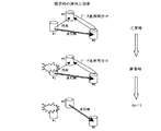
まず始めに、図5、図6を用いて同期転送によるコピー又は非同期リモートコピーを定義する。
【0028】
同期転送によるコピーとは、ホスト1から記憶サブシステム1に、データの更新(書込み)指示が有った場合に、その指示対象が附近地に設置された記憶サブシステム2にも書込むデータであるときは、記憶サブシステム2に対して、指示された更新(書込み)が終了してから、ホストに更新処理の完了を報告する処理手順をいう。ここで、附近地とは、いわゆるメトロポリタンネットワークと称される100km程度までの範囲を言うものとする。
【0029】
つまり、同期転送のリモートコピー(図5)では、ホスト1から受領した更新データブロックを記憶サブシステム1で受領し(▲1▼)、そのデータブロックを記憶サブシステム2に転送し(▲2▼)、書き込み完了後、これを記憶サブシステム1で受領し(▲3▼)、最後にホスト1に対し更新データブロックの書き込み完了を行う(▲4▼)。途中の処理に失敗した場合には、ホスト1に書き込み障害を報告する。
【0030】
同期転送によるコピーを実施すると、ホスト1に接続された近い方の記憶サブシステム1と、附近地に設置された遠い方の記憶サブシステム2のデータの内容が、巨視的にみて常に一致している。このため、災害により一方がその機能を失った場合であっても、他方の記憶サブシステムに災害直前までの状態が完全に保存されているので、残るシステムで迅速に処理を再開できる効果がある。尚、巨視的にみて常に一致とは、同期転送の機能を実施中には、制御装置や電子回路の処理時間の単位(μsec、msec)で、一致していない状態が有り得るが、データ更新処理完了の時点ではデータは必ず同一の状態になっていることを意味している。これは、附近地の記憶サブシステムへの更新データの反映が終了しない限り、ホストに近い側の記憶サブシステム1の更新処理を完了できないためである。
【0031】
一方、非同期リモートコピー(図6)とは、ホスト1からこれに接続された近い方の記憶サブシステム1に、データの更新(書込み)指示が有った場合、その指示対象が遠隔地に設置された記憶サブシステム2にも書込むデータであっても、記憶サブシステム1の更新処理が終わり次第、ホスト1に対し更新処理の完了を報告し、遠隔地の記憶サブシステム2におけるデータの更新(反映)が、近い方の記憶サブシステム1における処理とは非同期に実行される処理手順をいう。
【0032】
このため、近い方の記憶サブシステム1で必要とされる処理時間でデータ更新が終了するので、遠隔地の記憶サブシステム2へのデータの格納に起因する伝送時間、格納処理時間等により、ホスト1の処理が待たされることがない。ここで、遠隔地とは、いわゆるトランスコンチネンタルネットワークと称される、附近地より遠いが、距離の制約なく通信又はデータ転送可能な地点を言うものとする。
【0033】
より具体的には、非同期リモートコピーでは、ホスト1から受領した更新データブロックを記憶サブシステム1で受領し(▲1▼)、ホスト1に対し更新データブロックの書き込み完了を行う(▲2▼)。記憶サブシステム1は、自己のスケジュールで、ホスト1の処理とは非同期に、記憶サブシステム2へデータを転送する。
【0034】
遠隔地又は附近地へのデータ転送経路の複雑化、途中のデータ転送経路のボトルネックにより、データ転送中の当該データの順序性は保証されない(図6、点線の楕円内参照)。
【0035】
一般に、データ転送の性能を上げるため、多くは高速転送のため、転送元から複数の転送経路を用いてデータを転送する場合がある。また、転送先まで遠距離となると、転送元は1つの転送経路であっても介在する交換機、ルーターその他の通信中継機器により、転送先まで転送経路が1本であることは保証されない。このように複数の転送経路を用いてデータを転送する場合には、経路によっては時間的な差異が生じ、遅い経路と早い経路とを介してデータが送られるため、転送先においてデータの順序が保存されないのである。
【0036】
図6の楕円内に一例を示すが、データ転送経路上の順序を、Data#1、Data#2、Data#4、Data#3としている。記憶サブシステム2における更新順序はData#1、Data#2、Data#3、Data#4の順序である。記憶サブシステム2において、転送されてきたデータの順序をソートして正規の順序に並べ直しているからである。この更新処理の直後に不慮の災害が発生しても、データ更新の順序が守られているため、記憶サブシステム2のデータベースやジャーナルファイルシステムは回復処理を行うことができる。逆に、更新処理の直前に災害が発生したときは回復処理は不可能であるが、ホストへの応答とは非同期に、記憶サブシステム間で連続的に間断無くデータ転送処理を行うことで、データ不整合を極小化でき、巨視的に見て、常時、更新データの順序性を確保できる。
【0037】
本実施の態様では、ホスト1からデータブロックを受領し、記憶サブシステム2へ転送する際に、ホストからのデータ更新順序を示すシーケンス番号情報をデータに付して転送している。このため、記憶サブシステム2で、シーケンス番号情報に基づくソート制御を行い、順序性を保証して、データの格納を完了できる。このような一連のデータ転送・処理に必要な処理時間の後は、データの順序性が遠隔地の記憶サブシステム2において保持されている。このように非同期のコピーを、これに固有なデータ処理を連続して行うこと(非同期リモートコピー)で、常時、データ更新の順序性を保証することができる。
【0038】
非同期リモートコピーは、ホスト1の処理性能を落とさず、記憶サブシステム1及び2の間の距離を拡大できる特長があり、かつ、常時、データの順序性が保証されるため、広域データストレージシステムの利用者が自己の業務を遂行する上で、ほぼ任意の時点のデータベースやジャーナルファイルシステムの整合性を、遠隔地に設置された記憶サブシステムにおいて確保できる特長を有している。
【0039】
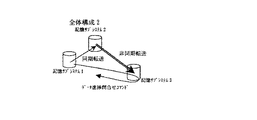
<広域データストレージシステム、その1>
図1に本発明の広域データストレージシステムの全体構成を示す。図9は本発明の別の広域データストレージシステムの全体構成を示す図である。図10は図1と図9の構成の組み合わせによる応用例を示す図である。
【0040】
図1において3ヵ所のデータセンタに記憶サブシステムを設置する。各データセンタには複数の記憶サブシステムが設置されても良いし、それらがリモートコピー機能を伴った接続形態となっていても良い。アプリケーションはデータセンタ1に接続されたホストで実行される。尚、ホストとデータセンタ1とのデータ転送経路は、ファイバーチャネル、メインフレームインタフェース、イーサネットLAN、公衆回線、インターネットその他専用回線である。
【0041】
データセンタ1とデータセンタ2は附近地に存在し、同期転送によりデータ転送し得る構成である。データセンタ1とデータセンタ3は遠隔地に存在し、これらの間は非同期リモートコピーの技術によりデータ転送し得る構成である。
【0042】
正常な運用形態では、ホストからデータセンタ1が受領した更新データは、データセンタ1に設置された記憶サブシステムに格納され運用される。この更新データは、附近地に設置されたデータセンタ2の記憶サブシステムへ、ファイバーチャネル、メインフレームインタフェース、イーサネットLAN、公衆回線、インターネットその他専用回線を介して、同期転送される。つまり、データセンタ1とデータセンタ2では、記憶サブシステム間のデータ整合性は巨視的には絶えず保たれている。
【0043】
正常な運用形態では、また、ホストからデータセンタ1が受領した上記の更新データを、遠隔地に設置されたデータセンタ3の記憶サブシステムへ、上記と同様な専用回線を介して、上記の同期転送処理と同時に、非同期リモートコピーの技術で転送される。尚、データセンタ1とデータセンタ2、データセンタ1とデータセンタ3、それぞれの間のデータ転送経路は同一種類の回線にする必要はない。
【0044】
データセンタ1とデータセンタ3との間は遠距離であり、この間の転送に起因する更新データの到着順序の不整合が生じる。また、転送元となるデータセンタ1の記憶サブシステムには、転送先で未反映のデータとなる差分データが、存在することとなる。しかし、本発明の非同期リモートコピーでは、所定の非同期転送に固有のデータ処理後は、データベースやファイルシステムの回復処理に必要な、ホストからのデータ順序性を保証しているために、不整合を生じていたデータの順序を回復させることが可能である。この結果、データセンタ1とデータセンタ3の記憶サブシステム間では、上記ホストから受領した更新データの順序性は保たれる。
【0045】
データセンタ2とデータセンタ3の間は、万一のリカバリ処理に備え、データを転送する通信線路は敷設・準備されているが、このストレージシステムの正常な運用時にはホストからの更新データは転送されない。データセンタ1での災害・障害発生の際に備え、正常な運用形態で、データ転送の進捗状態を問合せるコマンドが、この通信線路を介して、データセンタ2からデータセンタ3へ、又は逆にデータセンタ3からデータセンタ2へ、送受信されることとなる。尚、敷設・準備された通信線路は、ファイバーチャネル、メインフレームインタフェース、イーサネットLAN、公衆回線、インターネットその他専用回線である。
【0046】
正常時には、記憶サブシステム1と記憶サブシステム3との間の非同期リモートコピーにより為されたホストからの更新データの到着を、記憶サブシステム2から発せられる"データ進渉問合せコマンド"により、データセンタ2とデータセンタ3の間の通信線路を介して、問合せる。
【0047】
"データ進捗問合せコマンド"の起動は、記憶サブシステム2のスケジュールに従って為される。記憶サブシステム1からの同期転送によるデータの受領のタイミングで、当該コマンドを発行しても良いし、所定の時間間隔で纏めて問合せても良い。所定の時間間隔としては、例えば100msecから500msec毎に問合せても良いが、後述する転送状態/ビットマップの管理、これに基づく差分データの管理に時間が費やされ過ぎない程度となる。尚、1回の問合せで複数のビットマップを検査するようにしても良い。
【0048】
正常な運用時には、記憶サブシステム2と記憶サブシステム3との間で、直接、データの転送は行なわれない。このため、記憶サブシステム2が"データ進捗問合せコマンド"を発行して、記憶サブシステム1と記憶サブシステム3のデータ更新状況を把握する。
【0049】
万一、データセンタ1で障害が発生したときには、データセンタ2のホストを用いて、これまでのシステム運用を続行し(ホストのフェールオーバー)、記憶サブシステム2と記憶サブシステム3との間の差分データを、リカバリ処理に備えて敷設されたデータ転送の通信線路を用いてデータセンタ2からデータセンタ3へ転送する。差分データのみの転送で即時に広域データストレージシステムを回復させることが可能である。尚、フェールオーバーとは、プライマリーシステムからサブシステムへ切り替えることをいい、古くは、ホットスタンバイとも呼ばれていた。
【0050】
この後、データセンタ2からデータセンタ3へ、上記の通信線路を用いて、上述のような非同期リモートコピーを行うこととすれば、データセンタ1の復旧に伴う、データセンタ2とデータセンタ1との間の同期転送の復旧により、障害発生前の広域データストレージシステムを復旧させることがでる。但し、障害発生前後で、データセンタ1とデータセンタ2の役割が入れ替わっている。
【0051】
このように、附近地に存在する2つのデータセンタと、遠隔地に存在する2つのデータセンタとを統合し合計3つのデータセンタとすることで、リモートコピーの技術で連結する広域データストレージシステムとする。こうしておけば、中小規模の災害・障害のときは、附近地に存在する、相互に同期転送により連結されたデータセンタの一方で他方の代替を行うことができる。2つのデータセンタの記憶サブシステムのデータは同期転送により巨視的にみて一致しており、フェールオーバーが即時に行なえるからである。
【0052】
<広域データストレージシステム、その2>
図1のデータセンタ2とデータセンタ3との間の通信線路が非常用であるため、この通信線路を選択せず、障害・災害復旧後のデータセンタ1とデータセンタ3との間のデータ転送経路を選択する場合には、復旧後は、広域データストレージシステムは、図9の構成となる。
【0053】
図9は、記憶サブシステム1と記憶サブシステム2が同期転送で、記憶サブシステム2と記憶サブシステム3が非同期リモートコピーで、それぞれ、接続された例である。図1の広域データストレージシステムにおいて、データセンタ1からデータセンタ2へ運用を切り替え、データセンタ2を主たる運用サイトとし、災害・障害復旧後は、データセンタ2からデータセンタ1へデータを同期転送させる一方で、データセンタ1からデータセンタ3へデータを非同期転送させる構成となるからである。
【0054】
図9の場合において、直接データ転送に関与しない記憶サブシステム1から記憶サブシステム3へ、"データ転送進渉問い合せ"コマンドが発行され、データセンタ3が応答して結果をデータセンタ1へ返す構成となっている。また図10は、図1と図9を組み合せた構成である。記憶サブシステム3と5との間、記憶サブシステム2と5との間が、"データ進渉問い合せコマンド"の発行・応答の経路に該当する。
【0055】
上記の広域データストレージシステムの態様であれば、大規模な災害や、附近地に存在する2つのデータセンタに相次いで障害が発生した場合であっても、データセンタ3のホストへフェールオーバーすることで、災害直前のシステムが運用してきたデータを引き継いて処理でき、また、データの喪失を最小限度とすることができる。
【0056】
つまり、附近地にある2つのデータセンタが全滅する程度の災害が発生したときは、遠隔地に存在するデータセンタ3又は5(図1、図9、図10)の記憶サブシステムを生かすことができる。ホストからの更新データの順序性が確保されつつ、非同期リモートコピーが行なわれているからである。但し、災害による未反映のデータは復旧できない。
【0057】
<記憶サブシステムの構成について>
図1、図9及び図10では、同期転送によるコピー及び非同期リモートコピーの組み合わせを示している。本来、リモートコピーは、1論理ボリュームと1論理ボリュームをデータ転送技術で結合したものである。本発明では、1個の論理ボリュームに対するデータ受領を、同期転送し、更に非同期転送して、附近地と遠隔地の双方にリモートコピー機能でデータ送信制御を行なっている。
【0058】
これらは記憶サブシステムの制御装置のマイクロコードで実現される機能である。ホストや別の記憶サブシステムからの更新データは、一旦、キャッシュ5(図2)に格納される。この時点では、当該データは、まだ記憶サブシステム内のハードディスクドライブにRAID制御により書き込まれていない。キャッシュ5内で当該データの転送制御情報を加え、別の記憶サブシステムへリモートコピー転送したり、複数の記憶サブシステムとのリモートコピー構成を同時に実現する制御を行う。同期転送と非同期転送による組合せを守ることにより、いつ災害が発生しても、各データセンタでは、データの更新順序を保った、データベースやジャーナルファイルシステムがリカバリ可能な論理ボリュームを常時、保持していることとなる。
【0059】
図2は、記憶サブシステムの概略構成を示す図である。
【0060】
制御装置1は、ホスト及びリモートコピーの接続先とデータの送受を行うチャネルアダプタ3、ディスク装置2内のハードディスクドライブ7をディスクインタフェース8(ディスクI/F8)を介して制御するディスクアダプタ9を有する。
【0061】
チャネルアダプタ3とディスクアダプタ9は、それぞれ、マイクロプロセッサを有し、データ転送バス11・制御バス11を介してキャッシュメモリ5と接続されている。尚、バス構成は一例であり、必要に応じてクロスバー構成としても良い。また、制御装置1を複数設けてクラスタ構成とし、複数の制御装置1を連絡する共通の第3のバスを追加しても良い。
【0062】
ホストとの間や、リモートコピーの接続先とデータ送受を行う際の格納元は、キャッシュ5である。制御情報、構成管理情報、転送状態/ビットマップは、制御メモリ6に格納されている。
【0063】
リモートコピーには送信及び受信の機能があり、本実施例ではホストからI/Oを受領するチャネルアダプタを分けて搭載している。ホストから受領したI/Oは、一旦、キャッシュ5へ格納される。リモートコピーの転送先情報や後述する状態管理/ビットマップは、制御データとして制御メモリ6に格納され、マイクロコードにより制御される。
【0064】
キャッシュに受領したデータは、ディスクアダプタ9によりハードディスクドライブ7へRAID制御で書き込まれる。これとは別の処理である、マイクロコードを用いた制御により、予め定義されたリモートコピー転送先への送信制御が行なわれる。
【0065】
例えば、ホストから受領したデータが、後続するリモートコピーの対象であり、非同期転送によるデータ送信を行うと定義されていた場合には、キャッシュ5の内部のデータに対して、データ受領順にシーケンス番号を付与する。これはデータ更新を示すID情報でもある。シーケンス番号を付与されたデータは、チャネルアダプタ3のリモートコピー送信機能により、当該シーケンス番号と共に送信される。
【0066】
別の実施例で、ホストから受領した更新ブロックを、複数の論理ボリュームと接続するリモートコピー制御が定義されていた場合には、キャッシュメモリ5の内部のデータは、同期転送用に加工されると同時に、非同期転送用にも加工され、シーケンス番号が付与されて、それぞれ、チャネルアダプタ3で附近地又は、遠隔地に向けて送信される。
【0067】
図2は本発明を実現する一例であり、本発明はハードウエア構成に依存しない。リモートコピー接続が記憶サブシステム間で実現可能であれば、マイクロプロセッサによる論理的なサポート、マイクロコード制御で実現できるためである。
【0068】
<転送状態/ビットマップ>
図4は、転送状態/ビットマップ(適宜、ビットマップと略記する。)の一例を示したものである。これは、直接データ転送を行なっていない2つのデータセンタに設置された記憶サブシステムの内部に、災害・障害の復旧の際にペアを組むであろう相手(別のデータセンタに設置された記憶サブシステム)のデータ更新の進捗状況を知るために用意されたものである。例えば、図1ではデータセンタ2とデータセンタ3との間で、非常時のためにペアが組まれる。図9の広域データストレージシステムであれば、記憶サブシステム1と記憶サブシステム3との間で、図10では、記憶サブシステム2と記憶サブシステム5、記憶サブシステム3と記憶サブシステム5との間で、それぞれ、非常時のために、ペアが組まれることとなる。
【0069】
転送状態/ビットマップは、ペア(対)となる論理ボリュームに対して必要であり、本発明では1個の論理ボリュームの実体に対し、2個以上の転送状態/ビットマップを持ち得る。各ビットマップは、ペアやペアとなる場合を想定した定義付けにより、相手の論理ボリュームとの差分管理を行うために使われる。ビットマップの中のブロックナンバは、論理ボリュームの更新を管理する最小単位であるブロックに対応させた番号である。
【0070】
ホストI/Oは、このブロックナンバと同一単位である必要はない。ホストI/Oの単位は、通常、最小で512バイトとされ上限も設けられているが可変である。一方、ビットマップは、50kB弱の大きさ、又は700kB程度の大きさのものもあるが、20kBから1000kB程度まで種々の大きさがある。ホストI/Oの1ブロックに対して、必ずしも、1ビットマップが対応する訳ではない。
【0071】
ブロックナンバに対応するブロックの内容が更新されれば、差分管理は当該ブロックナンバ全体となり、同期(リシンク)を行うときに当該ブロックナンバのデータ全体が転送されることとなる。
【0072】
ビットマップは、ブロックナンバ毎に、当該論理ボリュームの更新された単位として、リモートコピーによるペアを再構築する際(再同期、リシンク)に当該更新されたブロックのみを転送する目的で、相手論理ボリュームに転送すべき"Update"情報を持つ。つまりUpdateフラグがOn(図4の実施例では1)、であれば転送対象であることを示す。通常のUpdateは、ホストからのコマンド単位で為されることから、カウンタ値が0であることに基づき、Updateフラグを0とする。
【0073】
ビットマップは更に、同一ブロックナンバで、複数回の更新を記録するカウンタ値を持つ。カウンタ値は、更新が無ければ"0"、3回更新されれば"3"となる。ブロックナンバーで表されるデータブロックの大きさが、ホストから更新されるデータブロックより大きい場合には、このカウンタ値を使うことにより確実に相手論理ボリュームへ更新データのみを転送できることとなる。
【0074】
後述の"データ進捗問合せコマンド"の中に格納されたブロックナンバとカウンタ値と、問合先の記憶サブシステムのビットマップのブロックナンバとカウンタ値との比較を、データコピー監視機能(後述)で行う。この際に、ある記憶サブシステムが持つカウンタ値が、この記憶サブシステムに送付されて来た"データ進捗問合せコマンド"に記述されたカウンタ値と等しいか大きい場合に、所定の記憶サブシステムのビットマップのカウンタ値は1減算される処理を受ける。
【0075】
送付されて来た"データ進捗問合せコマンド"に記述されたカウンタ値未満である場合は、その記憶サブシステムのビットマップのカウンタ値は何ら処理を受けない。そして減算したかしないかを、"データ進捗問合せコマンド"に応答して返す。
【0076】
その記憶サブシステムのビットマップのカウンタ値が、送付されて来た"データ進捗問合せコマンド"に記述されたカウンタ値"以上"の場合には、データ更新の進捗は、正常なリモートコピー機能により既に、その記憶サブシステムにおいて格納済み、書き込み済みであることを意味する。また"未満"の場合には、
データが未到着であることを意味している。
【0077】
図4のカウンタ値は有限であり、例えば、1バイト分をカウンタ値として割り当てた場合には、256回を超える管理はできない。この例では同一ブロックが256回を超えた更新を受けた場合には、最早、カウンタ値のUpを行わず、Updateフラグを恒久的に立ててしまう処理を行う。つまり図4でカウンタ値に"Over Flow"を意味する情報を格納する。
【0078】
このような恒久的な指定がなされると(図4、Over Flow)、ビットマップで特定される、恒久的指定のなされたブロックのUpdateフラグの解除(0を入力すること)は、相手論理ボリュームへの転送が完了しコピーが確定したことを、このビットマップを有する記憶サブシステムが認識するときまで行なわない。
【0079】
カウンタ値を用いた更新管理を行う理由を次に補足説明する。
【0080】
例えば、50kB程度のデータ量を有するトラックに対応させてビットマップの管理を行う場合に、この50kBのデータのうち、異なる3箇所が、異なる時刻において、それぞれ更新されたとする。トラックに対応させてビットマップ管理を行うのは、災害・障害後の復旧(再同期、リシンク)において扱う単位がトラック単位であるためである。
【0081】
カウンタ値による管理を行なわない場合には、Updateフラグのみ監視することとなるが、ある時刻でUpdateフラグが1であることのみを確認しても、その後の時刻に2度目、3度目の更新があった場合には、2度目以降のデータ更新を見逃してしまう。新たにカウンタ値の概念を導入して、ホストからのコマンド単位で為される同一データブロック(ここではトラックの一部)の更新を微細に監視することで、かかる不都合を防ぐことができる。
【0082】
次に、図2の制御装置1の内部でマイクロコードにより実現される転送状態/ビットマップの機能について定義する。論理ボリュームはリモートコピーの対となる論理ボリュームとの間で下記の転送状態を有する。これらは同期転送又は非同期転送に依存しない。
【0083】
1)「正常ペア状態」とは、データの順序性を保証して、双方のボリューム間で、同一のデータを2重に保持している状態をいう。
【0084】
2)「転送抑止ビットマップ登録の状態」とは、データの更新をビットマップに登録する状態をいう。未だペアの相手へデータの転送は行なわれていない。
【0085】
3)「ビットマップ使用のコピー状態」とは、「転送抑止ビットマップ登録の状態」から「正常ペア状態」への移行期をいう。2重化のためのコピーの初期状態に当たる。
【0086】
4)「障害状態」とは、障害によりデータを転送できない状態をいう。ビットマップに登録される。
【0087】
5)「ペア無ビットマップ登録状態」とは、本発明固有の特殊な状態をいう。災害・障害前に、相互にデータ更新状態を監視し保持する必要から生じた状態である。
【0088】
6)「ペア無状態」とは、ビットマップは用意されているが、未だペアを組んでおらず、データ更新の情報が登録されていない状態をいう。
【0089】
「ペア無ビットマップ登録状態」が存在することが本発明の特徴となる。この状態を持つことなく、"転送抑止ビットマップ登録の状態"というサスペンド(Suspend)状態で兼ねても良い。ここで、サスペンド状態とは、論理ボリュームへのデータの更新状態を、ビットマップでのみ管理し、リモートコピーによる転送制御を行なわない状態をいう。
【0090】
「ペア無ビットマップ登録状態」を持つのは、転送状態/ビットマップをペアで持つ必要からである(図3)。例えば、図1の広域データストレージシステムにおいては次の理由による。
【0091】
データセンタ3が保持するデータを監視するため、データセンタ2の記憶サブシステムの内部の論理ボリュームに対応して設けられた転送状態/ビットマップに、データセンタ3のデータ更新状態を持つ必要があり、且つ、データセンタ2が保持するデータを監視するため、データセンタ3の記憶サブシステムの内部の論理ボリュームに対応して設けられた転送状態/ビットマップに、データセンタ2のデータ更新状態を持つ必要があるためである。
【0092】
図9の広域データストレージシステムにおいては、データセンタ2の障害発生に備えて、データセンタ1とデータセンタ3のリモートコピーの差分管理情報から、データセンタ1とデータセンタ3との間でペア構築を目的として、「ペア無ビットマップ登録状態」をデータセンタ1とデータセンタ3で持つ必要がある。
この結果、記憶サブシステムやデータ転送経路のどこに障害が発生しても、状態把握が可能で、ビットマップによる未転送データブロックの記憶と、障害回復後に更新部分のみの差分転送が可能となる。
【0093】
転送状態/ビットマップの機能は、上記の様な制御を実現するマイクロコード及びビットマップと関連する制御テーブルから成る。具体的機能は、例えば、図2のマイクロプロセッサ4のマイクロコードと制御メモリ6で行なわれるが、先に示した様にマイクロコードの制御により自由に実装できる。例えば、マイクロプロセッサ10による実現も可能である。またマイクロプロセッサが1台のみの制御装置でも実現できる。
【0094】
<広域データストレージシステムの運用>
図3は、図1の広域データストレージシステムが正常に運用されている場合の基本的な制御方法を説明するための概略図である。正常運転ではデータ進捗問合せコマンドを記憶サブシステム2から記憶サブシステム3へ送信する。例えば、記憶サブシステム1の障害の際、実際の差分データの転送に際しては、記憶サブシステム2と記憶サブシステム3との間で、転送状態/ビットマップの機能を使用し、両方の記憶サブシステムのビットマップについて、論理演算を行う。その結果に基づき、相当するデータブロックのみを記憶サブシステム2から記憶サブシステム3へ転送している。図8に、図1の広域データストレージシステムのデータセンタ1に障害・災害が発生した場合において、非同期リモートコピーを再開させる概略の手順を示す。
【0095】
図8において、正常な運用では、データセンタ1から附近地のデータセンタ2へ同期転送によりデータの二重化が図られる一方で、遠隔地のデータセンタ3へは非同期転送によりデータの更新順序を確保したコピーが行なわれている。そして、データセンタ2の記憶サブシステム2のスケジュールで、データ進捗問合せコマンドがデータセンタ3に対し発行され、データセンタ2と3とは管理情報を遣り取りして、データの差分管理を行なっている。
【0096】
データセンタ1に災害・障害が発生すると、データセンタ2の記憶サブシステムは、非同期転送により、差分データをデータセンタ3へ送付し、即時に、データセンタ2と遠隔地のデータセンタ3によるシステム運用を回復できる。
【0097】
図3において、転送状態/ビットマップは、1論理ボリューム当り2個持ち、それぞれが、これらのビットマップを用いた機能を有する。記憶サブシステム1は、記憶サブシステム2と記憶サブシステム3に対し、転送状態/ビットマップ#1に対応する機能及びビットマップ#2に対応する機能を持つ。
【0098】
記憶サブシステム2と記憶サブシステム3は、同期転送及び非同期転送の各々について転送状態/ビットマップ#3及び#6の機能をそれぞれ持つ。これら#1と#3、#2と#6のそれぞれの機能は、正常運転の際には、"正常ペア状態"を格納している。
【0099】
転送状態/ビットマップ#4及び#5の機能は、それぞれ、記憶サブシステム2及び記憶サブシステム3が持っている。この広域データストレージシステムが正常に運用されているときには、転送状態/ビットマップ#4及び#5の機能は、上述の"ペア無ビットマップ登録"状態を保持する。
【0100】
転送状態/ビットマップ#4の機能は、記憶サブシステム3の論理ボリュームに対する差分管理を、転送状態/ビットマップ#5の機能は、記憶サブシステム2の論理ボリュームに対する差分管理を、それぞれ行う。
【0101】
図10の拡張として、ホストからのI/Oを受領する、第1のデータセンタに設置された記憶サブシステムの制御装置1が、N台の同期転送のコピー先と、M台の非同期リモートコピーのコピー先を持つ構成では、その制御装置1は、N+M個の転送状態/ビットマップの機能を有する。これに対応する、遠隔地又は附近地の記憶サブシステム(コピー先)も、転送状態/ビットマップを持つこととなる。この結果、制御装置1やデータ転送経路のどこに障害が発生しても、状態把握が可能で、ビットマップによる未転送データブロックの記憶と、災害回復の際の更新部分のみの差分転送が可能となる。
【0102】
<データコピー監視機能>
次に、データコピー監視機能について説明する。この機能には、ビットマップの制御機能、リモートコピーのステータス管理機能、構成管理機能、データ進捗問合せコマンドの制御機能、リモートコピーのデータ転送指示機能等が含まれる。
【0103】
図3の記憶サブシステム2の制御装置で、同期転送によるデータブロックを記憶サブシステム1から受領する。本データは記憶サブシステム2のキャッシュメモリに格納されディスクドライブで記憶される。この際、転送状態/ビットマップ#4の機能により当該データブロックが登録される。図4のビットマップに登録する。
【0104】
次に当該ブロックナンバとカウンタ値を格納した"データ進渉問い合せ"コマンドを記憶サブシステム2から記憶サブシステム3に対して発行する。発行のタイミングは同期転送に基づいても良いし、記憶サブシステム2の独自のスケジュールで行なっても良い。
【0105】
記憶サブシステム3の制御装置で、記憶サブシステム2からの"データ進渉問い合せ"コマンドを受領し、転送状態/ビットマップ#4のブロックナンバとカウンタ値を切り出し、記憶サブシステム3の該当する転送状態/ビットマップ#5のそれらと比較する。
【0106】
その結果、転送状態/ビットマップ#5のブロックナンバがUpdateフラグ1(更新)を示し、かつ、カウンタ値が転送されて来たもの以上であれば、同期転送に係るデータと、非同期リモートコピーに係るデータとが一致しているので、転送状態/ビットマップ#6の対応するブロックナンバから、カウンタ値を1減算する。
【0107】
減算の結果、カウンタ値が"0"となった場合には、Updateフラグを"0"とする。カウンタ値が"Over Flow"である場合には、何も操作しない。
【0108】
また、転送状態/ビットマップ#5に登録されていたカウンタ値が、記憶サブシステム2からの問合せコマンドから抽出されたカウンタ値未満であったり、Updateフラグが"0"(Off)で更新が示されなかった場合には、#5への更新は行なわず、これをデータ進捗問合せコマンドの結果として記憶サブシステム2へ返す。
【0109】
#5の転送状態/ビットマップの機能が、#6の転送状態/ビットマップのカウンタ値を減算するということは、記憶サブシステム1から同期転送により既に記憶サブシステム2へ到着したデータブロックが、記憶サブシステム1から記憶サブシステム3へ非同期転送により到着済であったことを意味している。
【0110】
データコピー監視機能は、本応答結果を用いて記憶サブシステム2の転送状態/ビットマップ機能の制御を行なう。記憶サブシステム3で"データ進渉問い合せ"コマンドのブロックナンバとカウンタ値が既に登録されていた旨の応答を返す場合(減算できた場合)には、記憶サブシステム2の制御装置でも転送状態/ビットマップの機能でカウンタ値の減算、Updateフラグの操作を同様に行う。
【0111】
当該コマンドの応答結果が、未登録であれば、記憶サブシステム1から記憶サブシステム3へのデータの非同期転送が未完であるとして、記憶サブシステム2の転送状態/ビットマップ#4の機能は、自己のビットマップに更新状況を保持する。これは後に更新差分部分のみを再同期させる際の対象となる。
【0112】
この時点で記憶サブシステム1が重大障害を持ち、記憶サブシステム2と記憶サブシステム3との間でリモートコピー構成を再構築(再同期、リシンク)しなければならない場合には、ビットマップを参照した結果、未転送のデータのみ、即ち、差分のデータブロックのみを、記憶サブシステム2から3へ転送すれば良い。その結果、差分データの転送だけで即時に"正常ペア"を構築できる。これを実現する機能を"データコピー監視機能"と呼ぶ。
【0113】
<正常な運用の際に、直接データ転送を行なわない記憶サブシステム間での差分管理方法、その1>
図9の広域データストレージシステムにおいて、記憶サブシステム2に障害が発生した場合に、記憶サブシステム1と記憶サブシステム3との間で非同期リモートコピーによるシステム運用の復旧を図るときを考える。
【0114】
このために、ホストからデータ更新を受領した記憶サブシステム1の制御装置1(図2)は、記憶サブシステム2の制御装置1の論理ボリュームに同期転送のコピーによるデータ転送を行う際に次の処理を行なう。
【0115】
転送するブロックの位置情報を、記憶サブシステム1の制御装置1に存在するビットマップに、記憶サブシステム3の論理ボリュームの更新情報を格納する。このとき既に転送したブロックが記憶サブシステム3において更新されていたときは、ビットマップのカウンタ値を1増加(インクリメント)する。
【0116】
記憶サブシステム1の制御装置1は、記憶サブシステム2の制御装置1に対して同期転送が完了した後、記憶サブシステム3の制御装置1に対して、同期転送したデータブロックが、記憶サブシステム2の制御装置1を経由して到着したか否かを問合せるため、記憶サブシステム1と記憶サブシステム3とを結ぶ通信線路を用いて、確認コマンドを発行する。
【0117】
確認コマンドには、ホストから受領した更新データの記憶サブシステムにおけるデータブロックのブロックナンバとカウンタ値が含まれている。確認コマンドを受領した記憶サブシステム3の制御装置1は、記憶サブシステム2の制御装置1経由で既に存在するデータブロックが、確認コマンドで問合されたブロックと一致するか否かを判定する。
【0118】
記憶サブシステム3の制御装置1は、記憶サブシステム2の制御装置1の論理ボリュームに対する転送状態/ビットマップの機能の他に、記憶サブシステム1の制御装置1の論理ボリュームに対する状態管理/ビットマップの機能を持つ。
【0119】
記憶サブシステム3の制御装置1は、記憶サブシステム2の制御装置からデータを受領すると、記憶サブシステム1の制御装置1の状態を格納すべく、自己の持つ転送状態/ビットマップへ登録する。このビットマップでは、論理ボリューム内のアドレスに関わるブロック位置に対する更新情報を有し、さらに複数回の同一ブロックに対する更新を管理するためにカウンタ値を有している。
【0120】
記憶サブシステム3の制御装置1の転送状態/ビットマップに登録された結果は、記憶サブシステム1の制御装置1から発行された確認コマンドのブロックナンバ及びカウンタ値と比較される。比較の結果、一致又はカウンタ値が確認コマンドにあったカウンタ値以上の場合には、データの到着が正常に完了していると判断し、転送状態/ビットマップの機能を用いてビットマップのカウンタを1減算する。
【0121】
他方、記憶サブシステム1の制御装置1は、記憶サブシステム3の制御装置1から返される結果が、記憶サブシステム3へデータブロックが記憶サブシステム2を経由して到着していることを示す場合には、上述の記憶サブシステム3の制御装置が為したように、転送状態/ビットマップの機能を用いてビットマップのカウンタを1減算する。
【0122】
以上のように、ビットマップを監視・管理することで、記憶サブシステム2が災害等により重大障害を持ち、同期及び非同期転送によるデータ送受が行なえなくなった場合であっても、ホストがI/Oを発行する記憶サブシステム1と、記憶サブシステム2の内容を非同期リモートコピーにより格納した記憶サブシステム3との間で、非同期リモートコピーを構成することができる。
【0123】
この際に記憶サブシステム1と3の、それぞれの制御装置の転送状態/ビットマップの機能により、論理ボリュームの全データをコピーすることなく、差分データのブロックのみを転送することにより、即時に、構築することができる。
【0124】
<正常な運用の際に、直接データ転送を行なわない記憶サブシステム間での差分管理方法、その2>
図1の広域データストレージシステムにおいて、ペアになっている論理ボリューム間、つまり、記憶サブシステム1と2並びに記憶サブシステム1と3、それぞれの間のデータ更新状態の管理のために、転送状態/ビットマップの機能が各論理ボリューム毎に用意される。
【0125】
記憶サブシステム1の制御装置1で障害が発生し、同期転送のコピー及び非同期リモートコピーの双方が継続不可となった場合には、記憶サブシステム2と3のそれぞれの制御装置1の間で、先ず差分データをコピーし両者を一致させる。
次いで、記憶サブシステム2と3の間で非同期リモートコピーを構成する。
【0126】
ホストから更新すべきデータを受領した記憶サブシステム1の制御装置1は、記憶サブシステム2の制御装置1へ同期転送によりデータブロックを送出し、これを記憶サブシステム2の制御装置1が受領する。記憶サブシステム2の制御装置1は、受領したデータブロックの位置情報(ブロックナンバ)を、記憶サブシステム3の制御装置1の配下の論理ボリュームの管理情報との比較のために、自己が保持する転送状態/ビットマップに格納する。転送状態/ビットマップは、受領したデータブロックが更新された場合には、カウンタ値を1増加(インクリメント)する機能を備え、複数回のデータブロックの更新を記録できる。
【0127】
記憶サブシステム2の制御装置1は、上記の転送状態/ビットマップへ所定の管理情報を登録した後、記憶サブシステム2の制御装置1と記憶サブシステム3の制御装置1との間を結ぶデータ転送経路を用いて、データブロックが記憶サブシステム3へ到着したか否かを問合せる確認コマンドを、記憶サブシステム3の制御装置1へ発行する。
【0128】
確認コマンドは、記憶サブシステム2の制御装置1が、同期転送により記憶サブシステム1から受領したデータブロックの位置情報であるブロックナンバと、データブロックが何回更新されたかを示すカウンタ値を含む。
【0129】
記憶サブシステム3の制御装置1は、記憶サブシステム1の制御装置1から、非同期リモートコピーの技術で受領したデータブロックの位置情報(ブロックナンバ)とカウンタ値を、記憶サブシステム2の制御装置1の配下の論理ボリュームの管理情報との比較のために、自己の制御装置1が持つ転送状態/ビットマップの機能を用いてビットマップに格納する。記憶サブシステム3の制御装置1は、ビットマップと確認コマンドの有する対応する値との比較を行う。
【0130】
記憶サブシステム2から3へ問合せた確認コマンドが有するブロックナンバとカウンタ値と、記憶サブシステム3の制御装置1が持つ、記憶サブシステム2の制御装置1の配下の論理ボリュームの管理情報である、これらの値とを比較して、確認コマンドの値と同一又はカウンタ値が確認コマンドのカウンタ値より大きい場合には、転送状態/ビットマップの機能で、そのデータブロックのカウンタ値を1減算する。
【0131】
減算した結果が0になる場合は、記憶サブシステム2と3との差分データはないことになるので、ビットマップの管理から削除する。上記の比較の結果が一致しない場合には、記憶サブシステム3の制御装置1は、ビットマップのカウンタ値を操作しない。
【0132】
記憶サブシステム3の制御装置1は、記憶サブシステム2の制御装置1に、確認コマンドの応答である判定結果を返す。この結果を記憶サブシステム2の制御装置1が参照し、比較がカウンタ値を減算した場合には、既に記憶サブシステム2と3の間で、同一のデータブロックの更新が正常に終了していると断定する。
【0133】
記憶サブシステム3に更新すべきデータブロックが届いていない場合には、記憶サブシステム2にのみ、更新に係るデータブロックが格納されていることになる。記憶サブシステム2の制御装置1は、自己の転送状態/ビットマップの機能でこれを記憶する。
【0134】
記憶サブシステム2の制御装置1が、記憶サブシステム3の制御装置1から確認コマンドの応答を受領し、記憶サブシステム3に更新すべきデータブロックが未到着であった場合には、記憶サブシステム2の制御装置1が持つ、記憶サブシステム3の論理ボリュームの更新状態に対応する転送状態/ビットマップのカウンタ値は減算しない。このことは、そのビットマップは、更新に係るデータブロックが、記憶サブシステム2と3との間で差分であることを示す。
【0135】
他方、データの到着完了を示した場合には、上記の転送状態/ビットマップの更新に係るデータブロックのカウンタ値を1減算する。カウンタ値が0のときは、記憶サブシステム2と3との間で、更新に係るデータブロックは同一であり不整合がないので、差分データのコピーの対象とはしない。
【0136】
このように、正常運用の際に、直接データ転送を行っていない記憶サブシステムの制御装置同士が、災害・障害からの回復を想定して、論理ボリューム間の差分データ管理を行っているため、記憶サブシステム間で差分データのみをコピーし不一致をなくすことが高速に行なえる。
【0137】
<フェールオーバー後のシステムの運用>
図7に、図1の広域データストレージシステムが、フェールオーバーにより状態を遷移して図9の構成となった場合の運用について簡単に説明する。図3で記憶サブシステム1に、図9で記憶サブシステム2に、図10で記憶サブシステム1、2又は4に、それぞれ重大な障害が起きた場合には、図7に示す様に、残存する2以上の記憶サブシステムの間で、リモートコピー構成の復帰を図ることとなる。
【0138】
本発明によれば、図7の様に、直接データ転送に関与していなかった論理ボリューム間(記憶サブシステム1と記憶サブシステム3との間)で、差分データのみコピーすれば、即時に、リモートコピーのペアを生成でき、リモートコピーの運用再開が可能である。
【0139】
本発明を実施しない場合には、図3の記憶サブシステム2と3の間、図9の記憶サブシステム1と3の間で、それぞれ、リモートコピー構成をつくるに際し、図3の構成では記憶サブシステム2から記憶サブシステム3に対し、図9の構成では、記憶サブシステム1から記憶サブシステム3に対し、それぞれ、記憶サブシステムが保持するデータのフルコピーを行なわなければならない。大規模のデータセンタでは、コピーに長時間を要し、リモートコピーの運用再開が遅くなる。長時間を要するコピー中に、再度、コピー元やデータ転送経路に障害・災害が発生すると、データは破壊され喪失することとなる。
【0140】
図11を用いて、図9の構成におけるデータコピー監視機能について簡単に説明する。
【0141】
データ進捗問合せコマンドは記憶サブシステム1から記憶サブシステム3に対して発行される。データコピー監視機能は図1の場合と一部処理が異なる。記憶サブシステム1が、同期転送により記憶サブシステム2へホストから受領した更新データを転送した後、記憶サブシステム1から3に対し、上述した"データコピー監視機能"を作動させる。つまり、"データ進渉問い合せ"コマンドを発行し、記憶サブシステム1の持つ転送状態/ビットマップ#1と、記憶サブシステム3の持つ転送状態/ビットマップ#3で、それぞれのUpdateフラグ、カウンタ値を登録し、所定の操作を行う。
【0142】
記憶サブシステム1から3に、ホストから記憶サブシステム1が受領したデータ(トラック)と同じデータが、記憶サブシステム3に届いたか否か、問合せた結果、未着であれば、記憶サブシステム1の転送状態/ビットマップ#1のビットマップは、そのまま保持する。結果が到着であれば、つまり、#3のビットマップのブロックナンバ、カウンタ値が同一であれば、Updateフラグを削除し、#1のビットマップを削除する。
【0143】
<再同期におけるその他の処理>
データコピー監視機能で検出した"データ進渉問い合せ"コマンドの応答結果に、エラーや不具合(タイムアウト)が生じたり、転送状態/ビットマップの機能に不具合が生じた場合には、障害・災害の際に行われるべき回復処理に関する差分管理を禁止する。
【0144】
転送状態/ビットマップの機能において、ビットマップは有限なカウンタ値の格納領域を有している。この有限値を超えて(オバーフロー)、同一データブロックが更新された場合には、そのデータブロックは、その後2以上の記憶サブシステム間で冗長度が維持されていても、災害・障害発生後に再同期処理、差分コピー処理が行なわれる際に、必ず更新対象として扱う。
【0145】
正常な運用において直接、データ転送を行なわない記憶サブシステム間で遣り取りされる問合せ(確認コマンド送出)に対し、所定時間、応答が無い場合は、タイムアウトであるとして再同期処理を禁止する。非同期リモートコピーによるペアの再構築処理や、差分データのみ転送する処理を行なわず、禁止する。ペアの相手のデータ更新状態を知ることができないため、そのままペアの再度構築処理を行なわしめることは妥当でないからである。
【0146】
<非同期転送におけるデータの整合性の管理>
例えば、ホストが接続する記憶サブシステム1と記憶サブシステム2とが、記憶サブシステム1から記憶サブシステム2にデータを複写する非同期転送で運用されているとする。この場合、もし、記憶サブシステム1におけるデータの書き込み順と、記憶サブシステム2におけるデータの書き込み順とが異なると、両記憶サブシステム1,2におけるデータの整合性が保証されなくなる。以下、このようなデータの不整合を回避するための仕組みについて説明する。
【0147】
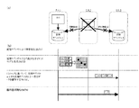
まず、各記憶サブシステム1,2における記憶資源の記憶領域に所定サイズ(例えば、16Kバイトごと)のブロックを区画して各ブロックに固有のブロック番号を割り当てる。そして、ホストからデータの書き込みがあったブロックについて、そのブロック番号とデータの書き込み順に付与したシーケンス番号との対応づけを制御メモリ6に管理する。例えば、図12に示すように、ブロック番号が56〜59のブロックにデータが書き込まれた場合には、図13に示すデータ管理情報を制御メモリ6に作成する。
【0148】
記憶サブシステム1から記憶サブシステム2への非同期転送に際しては、図14の転送データフォーマットに示すように、転送するデータに前記データ管理情報を付帯させる。一方、これを受信した記憶サブシステム2では、図15に示すように、データに付帯して送信されてきた前記データ管理情報を、制御メモリ6に管理する。ここで制御メモリ6に管理される前記データ管理情報、すなわち、シーケンス番号とブロックIDの組み合わせには、これに対応するデータのキャッシュメモリ上の位置情報も対応づけて記憶されている。記憶サブシステム2は、前記データ管理情報のシーケンス番号の順番にこれに対応するキャッシュメモリ上の前記位置情報に記憶されているデータを記憶資源に書き込んでいく。
【0149】
以上のようにして、ホストが記憶サブシステム1の記憶資源に書き込んだ順番どおりに、記憶サブシステム2の記憶資源においてもデータが書き込まれ、両記憶サブシステム1,2におけるデータの整合が保証されることになる。
【0150】
<マルチホップ方式>
図16(a)に示す広域データストレージシステムは、サイト1に設置された記憶サブシステム1と、サイト2に設置された記憶サブシステム2と、サイト3に設置された記憶サブシステム3とを備える。記憶サブシステム1には、この記憶サブシステム1を記憶手段として利用するホストが接続する。記憶サブシステム1と記憶サブシステム3との間も通信手段により接続される。
【0151】
記憶サブシステム1と記憶サブシステム2とは、記憶サブシステム1から記憶サブシステム2にデータを複写する同期転送で運用されている。また、記憶サブシステム2と記憶サブシステム3とは、記憶サブシステム2から記憶サブシステム3にデータを複写する非同期転送で運用されている。以下、このような形態のリモートコピー制御方法を「マルチホップ方式」と称する。なお、マルチホップ方式における各記憶サブシステム間の通信を同期転送とするか、非同期転送とするかは任意に設定される。また、これら以外の転送方式であってもよい。
【0152】
つぎに、図16(b)とともにマルチホップ方式によるデータ差分管理の詳細について説明する。
【0153】
記憶サブシステム1は、ホストから書き込み対象データとその書き込み要求(Write I/O)とを受信すると(S121)、書き込み対象データを自身の論理ボリューム(第1の記憶資源)に書き込むとともに、書き込み処理を行った順にシーケンス番号を付与し、これと前記データが書き込まれた論理ボリューム(第1の記憶資源)上の位置(格納位置)を特定する書き込み位置情報とを対応づけて(所定のテーブルに)記憶する(S122)。なお、書き込み位置情報は、例えば、セクタ番号、トラック番号等を用いて記述される。
【0154】
つぎに、記憶サブシステム1は、前記書込対象データを、これに付与された前記シーケンス番号とともに記憶サブシステム2に送信する(S123)。ここでこのような記憶サブシステム間で行われる、データとシーケンス番号の送信は、例えば、データ送信コマンドを送信した後に行われ、また、このコマンドには必要に応じて、前述したデータの書き込み位置情報が付帯される。
【0155】
記憶サブシステム2は、記憶サブシステム1から送られてくる前記書き込み対象データとシーケンス番号とを受信して、これを自身の論理ボリューム(第2の記憶資源)に書き込む。記憶サブシステム2は、前記書き込み処理が完了すると、その完了通知を記憶サブシステム1に送信する。
【0156】
記憶サブシステム2は、記憶サブシステム3に対し、適宜なタイミングで前記書き込み対象データと前記シーケンス番号とを送信する(S124)。
【0157】
つぎに、記憶サブシステム3は、前記データと前記シーケンス番号とを受信すると、前記書き込み対象データに対応して発行した前記シーケンス番号を、記憶サブシステム1に送信する(S125)。記憶サブシステム1は、記憶サブシステム3から送られてくるシーケンス番号を受信する。
【0158】
ここで記憶サブシステム1は、受信したシーケンス番号と、自身が記憶しているシーケンス番号とこれに対応する書き込み位置情報との対応づけ(テーブル)を対照することで、記憶サブシステム3の論理ボリューム(第3の記憶資源)に未反映のデータ、すなわち、差分データを把握することができる。なお、前記の対照は、例えば、記憶サブシステム3から受領した書き込み完了位置までのシーケンス番号と書き込み位置情報とをテーブルから削除することにより行われる(S126)。
【0159】
以上のようにしてマルチホップ方式における通常運用が行われる。
【0160】
つぎに、災害等により記憶サブシステム2が停止した場合の回復処理について説明する。
【0161】
図17(a)に示すように、記憶サブシステム1は、例えば、ハートビートメッセージの監視などの障害検出機能により、記憶サブシステム2の稼働状態をリアルタイムに監視している。以下では、ハートビートメッセージが途切れるなどして、記憶サブシステム1が記憶サブシステム2の障害発生を検知した場合に、記憶サブシステム1と記憶サブシステム3の間を、差分データのみを複写することによってその内容を一致させ、その後記憶サブシステム1と記憶サブシステム3の間を、非同期転送での臨時運用へ移行させる処理について、図17(b)とともに説明する。
【0162】
記憶サブシステム1は、記憶サブシステム2の障害発生を検知した場合(S131)、まず、制御メモリ6上に、自身の論理ボリューム(第1の記憶資源)の所定ブロック単位のデータ格納位置に対応づけたビットマップを生成し、自身が記憶している記憶サブシステム3において未反映の前記差分データについての前記シーケンス番号と前記書き込み位置情報との対応づけに基づいて、データ更新のあった前記ビットマップに対応する位置のビットをオンにする(S132)。
【0163】
つぎに、記憶サブシステム1の論理ボリュームの、前記ビットマップ上のオンになっている位置に格納されている差分データを、記憶サブシステム1から記憶サブシステム3の対応する格納位置に複写する(S133)。そして、この複写完了後、記憶サブシステム1から非同期転送により差分データが複写される形態で、臨時運用が開始される(S134)。
【0164】
ここでこの臨時運用への切り替えに際しては、記憶サブシステム2に障害が発生した場合でも、記憶サブシステム1のデータを記憶サブシステム3に全部複写する必要がなく、差分データのみを複写すればよい。このため、例えば、記憶サブシステム1と記憶サブシステム3との間の通信回線のデータ伝送量が充分でない場合でも、各記憶サブシステムにおける論理ボリュームに記憶されているデータを容易に同期させることができる。
【0165】
つぎに、記憶サブシステム2が復旧し、臨時運用から通常運用に切り替える際の一連の処理について説明する。
【0166】
まず、記憶サブシステム1は、自身の論理ボリューム(第1の記憶資源)に記憶している全てのデータを記憶サブシステム2の論理ボリューム(第2の記憶資源)に複写した後、記憶サブシステム1から記憶サブシステム2にデータを複写する同期転送での運用を開始する。すなわち、記憶サブシステム1は、ホストからの指示により自身の論理ボリューム(第1の記憶資源)にデータ書き込みを行った場合、書き込んだデータとシーケンス番号とを記憶サブシステム2に送信する。
【0167】
記憶サブシステム2は、記憶サブシステム1から送られてくる前記書き込んだデータとシーケンス番号とを受信して、これを自身の論理ボリューム(第2の記憶資源)に書き込む。記憶サブシステム2は、前記書き込み処理が完了すると、自身の論理ボリューム(第2の記憶資源)に対するデータ書き込みが行われた位置を特定する書き込み位置情報と、データの書き込み順に付与されるシーケンス番号とを対応づけて(所定のテーブルに)記憶する。この段階のデータ転送状態を図18に示す。
【0168】
つぎに、記憶サブシステム3は、記憶サブシステム1から送られてくる前記データと前記シーケンス番号とを受信して、前記データを自身の論理ボリューム(第3の記憶資源)に記憶するとともに(図18)前記対応づけにおける前記シーケンス番号を記憶サブシステム2に送信する(図示せず)。
【0169】
記憶サブシステム2は、記憶サブシステム3から送られてくるシーケンス番号を受信する。ここで記憶サブシステム2は、前記受信したシーケンス番号と、自身が記憶しているシーケンス番号と、これに対応する書き込み位置情報とを対照することで、記憶サブシステム3の論理ボリュームに未反映のデータ、すなわち、差分データを把握することができる。
【0170】
つぎに、臨時運用において記憶サブシステム1から記憶サブシステム3に複写する非同期転送の運用を停止する。この停止後、記憶サブシステム2は、自身の制御メモリ上に、自身の論理ボリューム(第2の記憶資源)の所定ブロック単位のデータ格納位置に対応づけたビットマップを生成し、自身が記憶している記憶サブシステム3において未反映の前記差分データについてのシーケンス番号と書き込み位置情報との対応づけに基づいて、データ更新のあった前記ビットマップの該当位置のビットをオンにする。
【0171】
つぎに、記憶サブシステム2は、前記ビットマップにより把握した、記憶サブシステム3の論理ボリューム(第3の記憶資源)において未反映となっている差分のデータとその書き込み位置情報とを記憶サブシステム3に送信する。
【0172】
記憶サブシステム3は、前記差分データと前記書き込み位置情報とを受信して、前記差分データを、自身の論理ボリューム(第3の記憶資源)の、前記書き込み位置情報により指定される該当データの格納位置に記憶する。これにより、記憶サブシステム2の論理ボリューム(第2の記憶資源)の内容と、記憶サブシステム3の論理ボリューム(第3の記憶資源)の内容との同期が取れることになる。以上の処理終了後、記憶サブシステム2と記憶サブシステム3との間の非同期転送による運用が開始され、図19に示す通常状態での運用が再開する。
【0173】
以上のようにして臨時運用から通常運用への切り替えが完了する。
【0174】
<マルチコピー方式>
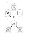
図20に示す広域データストレージシステムは、サイト1に設置された記憶サブシステム1と、サイト2に設置された記憶サブシステム2と、サイト3に設置された記憶サブシステム3とを備える。記憶サブシステム2にはこの記憶サブシステム2を記憶手段として利用するホストが接続する。なお、記憶サブシステム1と記憶サブシステム3との間も通信手段により接続される。
【0175】
記憶サブシステム1と記憶サブシステム2とは、記憶サブシステム2から記憶サブシステム1にデータを複写する同期転送で運用されている。また、記憶サブシステム2と記憶サブシステム3とは、記憶サブシステム2から記憶サブシステム3にデータを複写する非同期転送で運用されている。以下、このような形態のリモートコピー制御方法を「マルチコピー方式」と称する。なお、マルチコピー方式において、各記憶サブシステム間の通信を同期転送とするか、非同期転送とするかは前記の形態に限られず、任意に設定される。また、同期転送や非同期転送以外の転送方式であってもよい。
【0176】
つぎに、図20とともにこの実施例のデータ差分管理方式について説明する。記憶サブシステム2は、ホストから書き込み対象データとその書き込み要求(Write I/O)とを受信すると(S161)、書き込み対象データを自身の論理ボリューム(第2の記憶資源)に書き込む。また、記憶サブシステム2は、書き込まれたデータと、書き込み処理を行った順に付与したシーケンス番号とを、記憶サブシステム1に送信する(S162)。そして同時に、前記書き込まれたデータと前記付与したシーケンス番号とを、記憶サブシステム3に送信する(S164)。なお、前述のマルチホップ方式の場合と同様に、このような記憶サブシステム間で行われるデータとシーケンス番号の送信は、例えば、データ送信コマンドを送信した後に行われ、また、このコマンドには、必要に応じて前述したデータの書き込み位置情報が付帯される。
【0177】
つぎに、記憶サブシステム1は、記憶サブシステム2から送られてくる前記書き込み対象データとシーケンス番号とを受信して、前記書き込み対象データを自身の論理ボリューム(第1の記憶資源)に書き込む。その際、前記シーケンス番号と、これと前記データが書き込まれた論理ボリューム(第1の記憶資源)上の位置(格納位置)を特定する書き込み位置情報とを対応づけて(所定のテーブルに)記憶する(S163)。なお、書き込み位置情報は、例えば、セクタ番号、トラック番号等を用いて記述される。
【0178】
つぎに、記憶サブシステム3は、記憶サブシステム2から送られてくる前記書き込み対象データとシーケンス番号とを受信して、前記書き込み対象データを自身の論理ボリューム(第3の記憶資源)に書き込む。書き込みが完了すると、記憶サブシステム3は記憶サブシステム1に対し、前記書込み対象データとこれと対になっていた前記シーケンス番号とを記憶サブシステム1に送信する(S165)。記憶サブシステム1は、記憶サブシステム3から送られてくるシーケンス番号を受信する。
【0179】
ここで記憶サブシステム1は、前記受信したシーケンス番号と、自身が記憶しているシーケンス番号とこれに対応する書き込み位置情報との対応づけを対照することで、記憶サブシステム3の論理ボリューム(第3の記憶資源)に未反映のデータ、すなわち、差分データを把握することができる。なお、前記の対照は、例えば、記憶サブシステム3から受領した書き込み完了位置までのシーケンス番号と書き込み位置情報とをテーブルから削除することで行われる(S166)。
【0180】
以上のようにしてマルチコピー方式における通常運用が行われる。
【0181】
つぎに、災害等により記憶サブシステム2が停止した場合の回復処理について説明する。
【0182】
図21(a)に示すように、記憶サブシステム1は、例えば、ハートビートメッセージの監視などの障害検出機能により、記憶サブシステム2の稼働状態をリアルタイムに監視している。以下では、ハートビートメッセージが途切れるなどして、記憶サブシステム1が記憶サブシステム2の障害発生を検知した場合に、記憶サブシステム2に接続するホストに代えて、記憶サブシステム1と記憶サブシステム3の間を、差分データのみを複写することによってその内容を一致させ、その後記憶サブシステム1と記憶サブシステム3の間を、非同期転送での臨時運用へ移行させる処理について、図21(b)とともに説明する。
【0183】
記憶サブシステム1は記憶サブシステム2の障害発生を検知した場合(S171)、例えば、オペレータの操作により、記憶サブシステム2に接続していたホストの業務の運用が、記憶サブシステム1に接続する副ホストに引き継がれる。
【0184】
つぎに、記憶サブシステム1は、制御メモリ6上に、自身の論理ボリューム(第1の記憶資源)の所定ブロック単位のデータ格納位置に対応づけたビットマップを生成し、自身が記憶している記憶サブシステム3において未反映の前記差分データについてのシーケンス番号とデータ更新位置情報との対応づけに基づいて、データ更新のあった前記ビットマップの該当位置のビットをオンにする(S172)。
【0185】
つぎに、記憶サブシステム1の論理ボリュームの、前記ビットマップ上のオンになっている位置に対応する位置に格納されている差分データを、記憶サブシステム1から記憶サブシステム3に複写する(S173)。そして、複写完了後、記憶サブシステム1から同期転送によりデータが複写される形態で、臨時運用が開始される(S174)。
【0186】
ここでこの臨時運用への切り替えに際しては、記憶サブシステム2に障害が発生した場合でも、記憶サブシステム1のデータを記憶サブシステム3に全部複写する必要がなく、差分データのみを複写すればよい。このため、例えば記憶サブシステム1と記憶サブシステム3との間の通信回線のデータ伝送量が充分でない場合でも、各記憶サブシステムにおける論理ボリュームに記憶されているデータを簡単に同期させることができる。
【0187】
つぎに、記憶サブシステム2が復旧し、臨時運用から通常運用に切り替える際の一連の処理について説明する。
【0188】
まず、記憶サブシステム1は、自身の論理ボリューム(第1の記憶資源)に記憶している全てのデータを記憶サブシステム2の論理ボリューム(第2の記憶資源)に複写した後、記憶サブシステム1から記憶サブシステム2にデータを複写する同期転送での運用を開始する。なお、このとき記憶サブシステム1と記憶サブシステム3間での非同期転送も継続して行われる。
【0189】
記憶サブシステム1は、ホストから書き込まれたデータと、書き込み処理を行った順に付与したシーケンス番号とを、記憶サブシステム2に送信する。そして同時に、前記書き込まれたデータと前記付与したシーケンス番号とを、記憶サブシステム3にも送信する。
【0190】
記憶サブシステム2は、自身の論理ボリューム(第2の記憶資源)に対するデータ書き込みが行われた位置を特定する書き込み位置情報と、データの書き込み順に付与されるシーケンス番号との対応づけを記憶する(位置情報管理テーブル作成)。この段階での運用状態を図22に示す。
【0191】
記憶サブシステム3は、記憶サブシステム1から送られてくる前記データと前記シーケンス番号とを受信して、前記データを自身の論理ボリューム(第3の記憶資源)に記憶するとともに前記対応づけにおける前記シーケンス番号を記憶サブシステム2に送信する。
【0192】
記憶サブシステム2は、記憶サブシステム3から送られてくるシーケンス番号を受信する。ここで記憶サブシステム2は、前記受信したシーケンス番号と、自身が記憶している前記対応づけを対照することで、記憶サブシステム3の論理ボリュームに未反映のデータ、すなわち、差分データを把握することができる。
【0193】
つぎに、臨時運用において記憶サブシステム1から記憶サブシステム3に複写する非同期転送の運用を停止する。この停止後、記憶サブシステム2は、自身の制御メモリ上に、自身の論理ボリューム(第2の記憶資源)の所定ブロック単位のデータ格納位置に対応づけたビットマップを生成し、自身が記憶している記憶サブシステム3において未反映の前記差分データについてのシーケンス番号と書き込み位置情報との対応づけに基づいて、データ更新のあった前記ビットマップの該当位置のビットをオンにする。
【0194】
つぎに、記憶サブシステム2は、前記ビットマップにより把握した、記憶サブシステム3の論理ボリューム(第3の記憶資源)において未反映となっている差分のデータとその書き込み位置情報とを記憶サブシステム3に送信する。
【0195】
記憶サブシステム3は、前記差分データと前記書き込み位置情報とを受信して、前記差分データを前記書き込み位置情報に基づいて自身の論理ボリューム(第3の記憶資源)に記憶する。これにより、記憶サブシステム2の論理ボリューム(第2の記憶資源)の内容と、記憶サブシステム3の論理ボリューム(第3の記憶資源)の内容との同期が取れることになる。それから記憶サブシステム2から記憶サブシステム3への非同期転送が開始される。この段階での運用状態を図23に示す。
【0196】
ここで記憶サブシステム1に接続するホストの記憶サブシステム1へのデータ書き込み処理が完了しており、記憶サブシステム1と記憶サブシステム2の同期が取れている時に、記憶サブシステム1から記憶サブシステム2に対して行っていたデータの複写を、記憶サブシステム2から記憶サブシステム1に対して行うように切り替える。すなわち、同期が取れている状態で切り替えを行うことで、差分データを複写する等の作業が必要でなくなる。
【0197】
つぎに、記憶サブシステム1に接続するホストにより運用されている業務を、記憶サブシステム2に接続するホストに引き継ぐ。そして、記憶サブシステム2から記憶サブシステム3にデータを複写する同期転送による運用を開始することで、図24に示す通常状態での運用が再開することになる。
【0198】
以上のようにして臨時運用から通常運用への切り替えが完了する。
【0199】
<他の障害復旧方式>
つぎに、障害復旧方式のバリエーションについて説明する。
【0200】
図25に示すマルチホップ方式において、記憶サブシステム1がダウンした場合(a)には、記憶サブシステム2に副ホストを接続し、この副ホストにより記憶サブシステム1に接続するホストの業務を引き継ぐ。なお、記憶サブシステム2と記憶サブシステム3の間では、非同期転送での運用が行われている(b)。
【0201】
記憶サブシステム1が復旧した場合には、まず、記憶サブシステム2の全データを記憶サブシステム1に複写し、副ホストの業務を記憶サブシステム1に接続するホストに引き継ぐ。そして、前記の要領で、記憶サブシステム1と記憶サブシステム2との間のデータ転送方向を逆向きにすることにより、通常運用を再開する(c)。
【0202】
図26に示すマルチホップ方式において、記憶サブシステム3に障害が発生した場合(a)には、記憶サブシステム3の復旧後、記憶サブシステム2から記憶サブシステム3に全データを複写して記憶サブシステム3のデータを記憶サブシステム2と同期させ、記憶サブシステム1から記憶サブシステム2にデータを複写する同期転送および記憶サブシステム2から記憶サブシステム3にデータを複写する非同期転送による通常運用を再開する(b)。
【0203】
図27に示すマルチコピー方式において、記憶サブシステム1に障害が発生した場合(a)には、記憶サブシステム1の復旧後、記憶サブシステム2から記憶サブシステム1に全データを複写して記憶サブシステム1のデータを記憶サブシステム2と同期させ、記憶サブシステム2から記憶サブシステム1にデータを複写する同期転送および記憶サブシステム2から記憶サブシステム3にデータを複写する非同期転送による通常運用を再開する(b)。
【0204】
図28に示すマルチコピー方式において、記憶サブシステム3に障害が発生した場合には、記憶サブシステム3の復旧後、記憶サブシステム2から記憶サブシステム3に全データを複写して記憶サブシステム3のデータを記憶サブシステム2と同期させ、記憶サブシステム2から記憶サブシステム1にデータを複写する同期転送および記憶サブシステム2から記憶サブシステム3にデータを複写する非同期転送による通常運用を再開する。
【0205】
<複写元・複写先、書き込み位置情報の管理>
記憶サブシステム間でデータを転送する場合、データの転送元や転送先の設定や、その転送が同期・非同期いずれの方式で行われるかといった設定は、オペレータが各記憶サブシステムを操作して設定する場合(なお、この場合には、例えば、ある記憶サブシステムが障害を起して使えなくなった場合に、どの記憶サブシステムが次のデータの転送元になり、どの記憶サブシステムが次の転送先になるのかということを、システムの構成時に予め登録しておく)、記憶サブシステムに付帯するシステムが自動的に行ようにしている場合など、システムの構成に応じて様々な形態で行われる。
【0206】
また、シーケンス番号と書き込み位置情報の対応づけの管理は、例えば、オペレータが、転送元や転送先を記憶サブシステムに登録する操作を開始する契機で行う。
【0207】
<記憶サブシステムの選択方式>
図29に示す広域データストレージシステムは、記憶サブシステム1とこれに接続するホスト1h、記憶サブシステム1からデータが非同期転送される記憶サブシステム2および記憶サブシステム3を備えている。ホスト1hもしくは記憶サブシステム1に障害が発生した場合、迅速に記憶サブシステム2もしくは記憶サブシステム3のどちらか一方を主たる記憶サブシステムとして選択し、また、信頼性・保全性確保のため、これら2つの記憶サブシステム2および3においてデータを2重化管理する。以下、ホスト1hもしくは記憶サブシステム1に障害が発生した場合に行われる処理について説明する。
【0208】
記憶サブシステム2は、例えば、記憶サブシステム1から送信されてくるデータの有無や、記憶サブシステム1からあらかじめ設定された時間等に送られてくるハートビートメッセージの監視により、ホスト1hや記憶サブシステムに障害が発生したことを検知する。
【0209】
障害を検知した場合、記憶サブシステム2は、迅速に主たる記憶サブシステムを決定し、副ホスト2もしくは副ホスト3による臨時運用に切り替える。主たる記憶サブシステムの選択はつぎのようにして行われる。まず、障害を検知した記憶サブシステム2は、記憶サブシステム3に、前述したシーケンス番号のうち最新のシーケンス番号の送信を要求するメッセージを送信する。記憶サブシステム3は、前記メッセージを受信すると、自身が記憶している最新のシーケンス番号を記憶サブシステム2に送信する。
【0210】
記憶サブシステム2は、記憶サブシステム3から送られてきたシーケンス番号と、自身が記憶している最新のシーケンス番号とを比較して、より最新のシーケンス番号を受信している記憶サブシステムを、主たる記憶サブシステムとして選出し、選出した記憶サブシステムの識別子を選出候補として記憶するとともに、前記識別子を記憶サブシステム3に送信する。記憶サブシステム3は、送信されてきた前記識別子を受信し、これによりどの記憶サブシステムが主たるサブシステムとして選出されたのかを認知する。
【0211】
なお、以上の選出処理において、記憶サブシステム間の通信方式の性質などの諸事情により、記憶サブシステム2もしくは記憶サブシステム3が記憶しているシーケンス番号に抜けが存在することがある。そこで、このような場合には、連続しているシーケンス番号のうちで最新のものを、前記の比較に用いる。
【0212】
主たる記憶サブシステムが選出されると、つぎに、記憶サブシステム2と記憶サブシステム3とによりデータの二重化管理を行うため、両者が記憶しているデータの内容を一致させる。これは、記憶サブシステム間で全データの複写や差分データの複写により行われる。記憶サブシステム間でデータが一致すると、主たる記憶サブシステムとして選出された記憶サブシステムは、自身に接続している副ホストに、自身が主たる記憶サブシステムとなる旨を送信する。副ホストはこれを受信して代行運用を開始する。また、記憶サブシステム2と記憶サブシステム3との間で、同期転送もしくは非同期転送によるデータの二重化管理が開始される。
【0213】
なお、以上の説明では、記憶サブシステム2が記憶サブシステム3から最新のシーケンス番号を取得して、主たる記憶サブシステムを選出するようにしているが、この処理は記憶サブシステム3が行ってもよい。
【0214】
また、記憶サブシステム1乃至記憶サブシステム3の3台構成の記憶サブシステムにおいて、記憶サブシステム1の障害発生時に代行して運用される他の記憶サブシステムを選出する仕組みを一例として説明したが、前述の仕組みは、4台以上の記憶サブシステムで構成される広域データストレージシステムにも適用することができる。
【0215】
<キャッシュメモリ上のデータの管理>
ホストが接続する一次の記憶サブシステムに、この一次の記憶サブシステムのデータのリモートコピー先である1以上の二次の記憶サブシステムが接続する系における、一次の記憶サブシステムのキャッシュメモリ上のデータの管理に関する実施例について説明する。
【0216】
前記の系において、一次の記憶サブシステムから二次の記憶サブシステムに複写(リモートコピー)する必要の無いデータについては、一次の記憶サブシステムの記憶資源にデータを書き込んだ後は、そのデータを当該記憶サブシステムのキャッシュメモリ上から消去されてもよいが、二次の記憶サブシステムに複写する場合には、少なくともそのデータを二次の記憶サブシステムに送信するまではキャッシュメモリ上に残しておく必要がある。また、転送先となる二次の記憶サブシステムが複数存在する場合には、通信手段の違いや運用上の差異などにより、通常、二次の記憶サブシステムについての転送が同時に行われるわけではないので、このような場合には、全ての二次の記憶サブシステムに対する転送が終了するまで、データをキャッシュメモリ上に残しておく仕組みが必要である。
【0217】
そこで、一次の記憶サブシステムにおいて、キャッシュ上に置かれているデータについて、一次の記憶サブシステムに接続する二次の各記憶サブシステムについての転送が完了しているかどうかを管理するようにする。具体的には、例えば、図30に示すように、キャッシュメモリ上に区画された記憶ブロック(#1,〜,#n)ごとに、それぞれの記憶ブロックに格納されているデータについて、二次の各記憶サブシステムへの転送が完了しているかどうかを示すテーブルを、一次の記憶サブシステムにおいて管理するようにする。
【0218】
なお、このテーブルにおいて、ビット「0」は転送が完了していることを示し、ビット「1」は転送が完了していないことを示す。ホストからのデータが一次の記憶サブシステムに書き込まれた時に、データが書き込まれた記憶ブロックの転送先となっている二次の記憶サブシステムに対応するビットに「1」がセットされる。ある記憶ブロックの「1」がセットされているビットのうち、データの転送が完了した二次の記憶サブシステムについてのビットは、転送完了後に「0」となる。
【0219】
そして、全ての二次の記憶サブシステムについてのビットが「0」となった記憶ブロックに格納されているデータについては、キャッシュメモリ上から消去してもよいということになる。
【0220】
【発明の効果】
図1、図9及び図10で示した、3つ以上のサイトを有する広域データストレージシステムにおいて、いずれかのサイトに、いつ災害・障害が発生しても、巨視的に見て常時、データの順序性を保証した論理ボリュームを残すことができる。
【0221】
直接データ転送に関与していなかった論理ボリューム間、例えば、図7の記憶サブシステム1と記憶サブシステム3との間で、差分データのみコピーすれば、即時に、非同期リモートコピーのペアを生成でき、広域データストレージシステムの運用再開が、即時に、可能となる効果がある。
【0222】
本発明では、記憶サブシステムの内部にリモートコピーを実施するための冗長な論理ボリュームを必要としないため、記憶サブシステムのメモリー資源の使用効率が上がり、記憶サブシステムのコストパフォーマンスが向上する効果がある。
【図面の簡単な説明】
【図1】本発明に係る広域データストレージシステムの全体構成の一例を示した説明図である。
【図2】記憶サブシステムの一例を示した概念図である。
【図3】図1の構成において、データコピー監視機能を説明するための概念図である。
【図4】本発明を実現するための転送状態/ビットマップの一例を示した図である。
【図5】一般的な同期転送によるコピーの制御の概略を説明するための図である。
【図6】非同期リモートコピーの制御の概略を説明するための図である。
【図7】図9の全体構成において、データセンタ2に障害・災害が発生した場合の復旧の様子を示した説明図である。
【図8】図1の全体構成において、データセンタ1に障害・災害が発生した場合の復旧の様子を示した説明図である。
【図9】本発明に係る広域データストレージシステムの全体構成の別の一例を示した説明図である。
【図10】データセンタを4拠点以上設置した場合の、本発明に係る広域データストレージシステムの全体構成の別の一例を示した説明図である。
【図11】図9の全体構成において、データコピー監視機能を説明するための概念図である。
【図12】本発明の一実施例による非同期転送におけるデータの整合性の管理方法を説明するための、記憶資源のデータを管理する単位であるブロックの概念を示す図である。
【図13】本発明の一実施例による非同期転送におけるデータの整合性の管理方法を説明するための、データ管理情報の概念を示す図である。
【図14】本発明の一実施例による非同期転送におけるデータの整合性の管理方法を説明するための、転送データのフォーマットの概念を示す図である。
【図15】本発明の一実施例による非同期転送におけるデータの整合性の管理方法を説明するための、記憶サブシステム2において管理されるデータ管理情報の概念を示す図である。
【図16】(a)はマルチホップ方式の広域データストレージシステムの概念を示す図であり、(b)は(a)に記載の記憶サブシステムにより行われる処理の流れを示す図である。
【図17】(a)はマルチホップ方式の広域データストレージシステムの概念を示す図であり、(b)は(a)に記載の記憶サブシステムにより行われる処理の流れを示す図である。
【図18】マルチホップ方式において、臨時運用から通常運用に切り替え途中段階における記憶サブシステム間のデータ転送状態を示す図である。
【図19】マルチホップ方式において、臨時運用から通常運用への切り替え終了後の記憶サブシステム間のデータ転送状態を示す図である。
【図20】(a)はマルチコピー方式の広域データストレージシステムの概念を示す図であり、(b)は(a)に記載の記憶サブシステムにより行われる処理の流れを示す図である。
【図21】(a)はマルチコピー方式の広域データストレージシステムの概念を示す図であり、(b)は(a)に記載の記憶サブシステムにより行われる処理の流れを示す図である。
【図22】マルチコピー方式において、臨時運用から通常運用に切り替え途中段階における記憶サブシステム間のデータ転送状態を示す図である。
【図23】マルチコピー方式において、臨時運用から通常運用に切り替え途中段階における記憶サブシステム間のデータ転送状態を示す図である。
【図24】マルチコピー方式において、臨時運用から通常運用への切り替え終了後の記憶サブシステム間のデータ転送状態を示す図である。
【図25】(a)〜(c)は、マルチホップ方式における障害復旧方式の他のバリエーションを説明する図である。
【図26】(a)、(b)は、マルチホップ方式における障害復旧方式の他のバリエーションを説明する図である。
【図27】(a)、(b)は、マルチコピー方式における障害復旧方式の他のバリエーションを説明する図である。
【図28】(a)、(b)は、マルチコピー方式における障害復旧方式の他のバリエーションを説明する図である。
【図29】障害発生時において、本番業務を代行させる記憶サブシステムの選択方式を説明する、広域データストレージシステムの概念図である。
【図30】本発明の一実施例による、キャッシュメモリ上のデータの管理方法における、二次の各記憶サブシステムへのデータの転送状態を管理するテーブルを示す図である。
【符号の説明】
1 記憶サブシステムの制御装置
5 キャッシュメモリ
6 制御メモリ
#1〜#6 転送状態/ビットマップ。[0001]
BACKGROUND OF THE INVENTION
The present invention relates to a wide area data storage system capable of recovering from a failure immediately after a failure of the external storage device due to a disaster, and in particular, the external storage devices are installed at a distance of 100 km to several hundred km from each other. The present invention relates to a wide area data storage system including three or more external storage devices that perform complementary operations.
[0002]
[Prior art]
Japanese Patent Application Laid-Open No. 11-338647 by the applicant of the present application discloses that the system and data are duplexed synchronously or asynchronously. Japanese Patent Laid-Open No. 2000-305856 filed by the applicant of the present application discloses a technique for asynchronously copying data to a remote place.
[0003]
In this way, the applicant of this case receives special control information that specifies the order of data from a large-scale computer system, a server, a personal computer on a network, and other host computer systems (hereinafter referred to as hosts). The external storage device (hereinafter referred to as a storage subsystem) that has received the data always guarantees the order of the data to the second storage subsystem installed at a remote location. Asynchronous remote copy technology that writes continuously to the second storage subsystem by asynchronous transfer without interruption.
[0004]
In addition, when copying using the synchronous transfer technology, data update processing between the host and the storage subsystem connected thereto, and a storage subsystem installed in the vicinity of the storage subsystem or in a remote location. Since the copy control with the system is linked, the data is always consistent between the two storage subsystems macroscopically, and the writing order is also guaranteed at the same time. If an appropriate data transfer path is selected, copying by synchronous transfer is possible even when the distance between the two storage subsystems exceeds 100 km.
[0005]
Nowadays, there is a growing recognition that it is important to store and hold data safely, and many people in the data storage market demand a disaster recovery system. As in the prior art, two data storage bases are provided and the two points are connected by synchronous transfer or asynchronous transfer. However, the market demands third and fourth data storage bases (hereinafter referred to as data centers) and desires to build a complete or nearly complete disaster recovery system between them.
[0006]
The reason for this is that if three or more data centers are installed, even if one of them is hit by a disaster, data redundancy will be made between the remaining centers in order to reduce the risk of a disaster that will continue to occur. There is an expectation that recovery and maintenance will be achieved.
[0007]
In the conventional technology, when three or more data centers are constructed, I / O received from the host is received by the logical volume of the only storage subsystem and transferred to multiple data centers using remote copy technology. There was not enough consideration when doing. For example, if one data center goes down due to a disaster, a logical volume that guarantees the order of data can be constructed between the remaining two or more data centers, or the update status can be inherited and data inconsistencies can be eliminated. In addition, there was not enough consideration regarding the issue of whether it is possible to reconstruct a system that allows copying to nearby or remote locations.
[0008]
[Problems to be solved by the invention]
Since it is unclear when a disaster will occur, the order of data updates must be maintained at all times among three or more data centers.
[0009]
For this reason, the host does not have a special function, concatenates multiple remote copy configurations, distributes data received by the same logical volume to another storage subsystem at a remote location or a nearby location, and at any point in time. Even if a disaster occurs, a wide area data storage system that always guarantees the data update order from the host in the storage subsystem of each data center must be configured.
[0010]
In the wide area data storage system according to the present invention, the above problem is solved by copying data to another storage subsystem without providing a redundant logical volume inside the storage subsystem.
[0011]
Further, in the wide area data storage system according to the present invention, as a recovery operation after a disaster, it is assumed that the wide area storage system is reconfigured, and during normal operation, between storage subsystems that are not directly transferring data, Management information is exchanged, and the update state of data is monitored and managed by each storage subsystem. Then, in recovery work after a disaster (resynchronization, resync), by transferring only the difference in data held by each storage subsystem immediately before the occurrence of the disaster, it is possible to instantly replace the host and the application Continue execution.
[0012]
<About guaranteeing the order of data update>
Here, a supplementary description will be given of the temporal range for maintaining order.
[0013]
The I / O issued from the host is written in the storage subsystem, and the host recognizes the data write completion report reported by the storage subsystem, and the host executes the following steps. If the host does not receive the data write completion of the storage subsystem or if there is a failure report, it does not issue the next I / O normally. Therefore, the order of data writing should be maintained by the storage subsystem performing some processing of order preservation before and after the host receives a write completion report from the storage subsystem.
[0014]
In remote transfer of synchronous transfer, the data to be transferred and copied is written to a storage subsystem at a nearby location or a remote location (hereinafter simply referred to as “separate location”), and writing from the storage subsystem at another location is completed. After receiving it, a write completion report is sent to the host. Compared with the case where remote copying is not performed, the processing related to remote copying and the data transfer processing time take longer, and the performance is delayed. If the connection distance in the remote copy is extended, the processing time associated with the data transfer increases, and the performance of the host I / O processing is further reduced by performing the remote copy. One way to overcome this is asynchronous transfer.
[0015]
In asynchronous transfer, the storage subsystem that has received I / O from the host transfers data to a separate storage subsystem and does not wait for the write to the separate storage subsystem to complete before receiving I / O from the host. Storage subsystem returns a write completion report to the host. Thereby, the data transfer between the storage subsystems is not related to the host I / O processing and can be executed asynchronously with the host I / O processing. However, if the order of data arrival from the host is observed and data is not written to a separate storage subsystem, the data order of the separate storage subsystem will not be maintained, and there will be data loss between both storage subsystems. There is a possibility of matching. Such a possibility can be minimized by adding a function that always guarantees the order of data.
[0016]
The storage subsystem in the remote area is usually late in updating data compared to the storage subsystem that received the host I / O. However, as long as the data arrival order from the host is observed and data is written to the storage subsystem, the data There is no contradiction in the order, and recovery is possible by a journal file system or database recovery processing.
[0017]
On the other hand, there is a method of reflecting data by remote copying to a separate storage subsystem without maintaining the order of the data. This method sends data received from the host up to a certain point to another place and summarizes it in the storage subsystem. At the stage where data writing up to a certain point is completed, the data transfer is terminated, and thereafter, until the next summary writing, the remote copy data transfer is suppressed, the data ordering during the suppression, the I received from the host Ensure consistency of / O.
[0018]
This method does not require a function to add data order information, but it stores data for a certain amount of update, transfers the update in a batch, and completes data writing at the stage where all writing to the remote is complete. Guarantees sex. In this method, if a failure occurs during remote copy, the data update on the remote side is not updated while maintaining the order, and there is a possibility that the data will be destroyed. Data integrity can be guaranteed only while the remote copy data transfer is stopped, which is called adaptive.
[0019]
According to the "remote copy by asynchronous transfer that always guarantees data order" that the applicant owns, when the completion report is returned to the host, the storage subsystem performs processing to guarantee the data order. It is a feature. Regardless of the overhead in the storage subsystem controller and the delay time of internal processing, the data order information is managed for each block when it is returned to the host, so that the order is always guaranteed.
[0020]
In practice, control and management for each block is performed in a time considerably shorter than the I / O issue interval received from the host. On the other hand, the value for timeout (Timeout) that cannot wait for data distribution in the storage subsystem on the remote side can be set to 1 hour or more. What is important is that the applicant's remote copy technology assigns order information to data and transfers data blocks, and based on this, writes data in the order of data. This is because even if the time difference between local / remote data updates is half a day, if the order is correct, it is better than the inconsistency that loses all the update data.
[0021]
[Means for Solving the Problems]
Three or more data centers are connected to each other by a transfer path capable of transferring data synchronously and asynchronously, a communication line capable of exchanging predetermined management information, and data update progress management means.
[0022]
Here, the update progress management means is provided in each storage subsystem, and in order to cope with a disaster that does not know when it occurs, the update status of the data update in the storage subsystem installed in another data center is appropriately It is a means for monitoring and mutually grasping the data update status of the storage subsystem.
[0023]
Specifically, each storage subsystem that is not directly transferring data has a transfer status / bitmap, one of which queries which location of the transfer block has been updated, and the other responds to this. Thus, it has a function of monitoring and managing the progress of data update (remote copy).
[0024]
DETAILED DESCRIPTION OF THE INVENTION
The storage subsystems installed in three or more data centers are connected by synchronous transfer.
[0025]
In addition, they are linked by an asynchronous remote copy technology that guarantees the order of data continuously at all times. Then, the host receives the data received by the primary storage subsystem from the host from the storage subsystem of one primary data center to each of the storage subsystems of the other two or more data centers other than this. Transfer and store continuously while maintaining the updated order.
[0026]
Since the data is redundantly configured to guarantee the update order from the host, even if a disaster or failure occurs in the data center, each storage subsystem among the remaining data center storage subsystems By transferring only the difference data between them, it is possible to immediately recover the operational configuration of the remote copy, or to minimize data loss.
[0027]
<About synchronous and asynchronous>
First, a copy by asynchronous transfer or an asynchronous remote copy is defined using FIGS.
[0028]
The copy by synchronous transfer is data to be written to the
[0029]
That is, in the remote copy of synchronous transfer (FIG. 5), the update data block received from the
[0030]
When copying by synchronous transfer is performed, the data contents of the
[0031]
On the other hand, asynchronous remote copy (FIG. 6) means that when there is a data update (write) instruction from the
[0032]
For this reason, since the data update is completed in the processing time required in the
[0033]
More specifically, in the asynchronous remote copy, the update data block received from the
[0034]
Due to the complexity of the data transfer path to the remote place or the nearby place and the bottleneck of the data transfer path in the middle, the order of the data during the data transfer cannot be guaranteed (see FIG. 6, inside the dotted ellipse).
[0035]
In general, in order to improve the performance of data transfer, data is often transferred from a transfer source using a plurality of transfer paths for high-speed transfer. When the transfer destination is a long distance, even if the transfer source is a single transfer route, it is not guaranteed that there is only one transfer route to the transfer destination by an intervening exchange, router, or other communication relay device. In this way, when transferring data using a plurality of transfer routes, there is a time difference depending on the route, and data is sent via a slow route and a fast route. It is not saved.
[0036]
An example is shown in the ellipse of FIG. 6, but the order on the data transfer path is
[0037]
In this embodiment, when a data block is received from the
[0038]
Asynchronous remote copy has the advantage that the distance between the
[0039]
<Wide area data storage system,
FIG. 1 shows the overall configuration of a wide area data storage system of the present invention. FIG. 9 is a diagram showing an overall configuration of another wide area data storage system of the present invention. FIG. 10 is a diagram showing an application example in which the configurations of FIGS. 1 and 9 are combined.
[0040]
In FIG. 1, storage subsystems are installed at three data centers. Each data center may be provided with a plurality of storage subsystems, or they may be connected with a remote copy function. The application is executed on a host connected to the
[0041]
The
[0042]
In a normal operation mode, update data received by the
[0043]
In a normal operation mode, the update data received by the
[0044]
The
[0045]
A communication line for transferring data is laid and prepared between the
[0046]
At normal times, the arrival of update data from the host, which is performed by asynchronous remote copy between the
[0047]
The activation of the “data progress inquiry command” is performed according to the schedule of the
[0048]
During normal operation, data transfer is not directly performed between the
[0049]
Should a failure occur in the
[0050]
Thereafter, if the above-mentioned asynchronous remote copy is performed from the
[0051]
In this way, by integrating the two data centers existing in the vicinity and the two data centers existing in the remote areas into a total of three data centers, a wide-area data storage system connected by remote copy technology, To do. In this way, in the case of a small / medium-scale disaster / failure, it is possible to replace one of the data centers existing in the vicinity and connected to each other by synchronous transfer. This is because the data in the storage subsystems of the two data centers coincide macroscopically by synchronous transfer, and failover can be performed immediately.
[0052]
<Wide area data storage system,
Since the communication line between the
[0053]
FIG. 9 shows an example in which the
[0054]
In the case of FIG. 9, a “data transfer progress inquiry” command is issued from the
[0055]
In the case of the above wide area data storage system, even if a large-scale disaster or a failure occurs in two data centers in the vicinity, failover to the host in the
[0056]
In other words, when a disaster occurs to the extent that two data centers in the vicinity are annihilated, the storage subsystem of the
[0057]
<Configuration of storage subsystem>
1, FIG. 9, and FIG. 10 show a combination of copy by asynchronous transfer and asynchronous remote copy. Originally, remote copy is a combination of one logical volume and one logical volume using a data transfer technique. In the present invention, data reception for one logical volume is transferred synchronously, and further asynchronously transferred, and data transmission control is performed by the remote copy function for both the nearby and remote locations.
[0058]
These are functions implemented by the microcode of the storage subsystem controller. Update data from the host or another storage subsystem is temporarily stored in the cache 5 (FIG. 2). At this point, the data has not yet been written to the hard disk drive in the storage subsystem by RAID control. The transfer control information of the data is added in the
[0059]
FIG. 2 is a diagram showing a schematic configuration of the storage subsystem.
[0060]
The
[0061]
Each of the
[0062]
The storage source for data transmission / reception with the host or remote copy connection destination is the
[0063]
Remote copy has transmission and reception functions. In this embodiment, channel adapters that receive I / O from the host are separately installed. The I / O received from the host is temporarily stored in the
[0064]
The data received in the cache is written to the
[0065]
For example, if the data received from the host is the target of the subsequent remote copy and data transmission by asynchronous transfer is defined to be performed, the sequence numbers are set in the order of data reception for the data in the
[0066]
In another embodiment, when remote copy control for connecting an update block received from a host to a plurality of logical volumes is defined, data in the
[0067]
FIG. 2 is an example for realizing the present invention, and the present invention does not depend on the hardware configuration. This is because if a remote copy connection can be realized between storage subsystems, it can be realized by logical support by a microprocessor and microcode control.
[0068]
<Transfer status / bitmap>
FIG. 4 shows an example of the transfer state / bitmap (abbreviated as “bitmap” where appropriate). This is because inside a storage subsystem installed in two data centers that are not directly transferring data, a partner that will form a pair in the event of a disaster / failure recovery (a storage installed in another data center). This is prepared to know the progress of the data update of the subsystem. For example, in FIG. 1, a pair is formed between the
[0069]
A transfer state / bitmap is necessary for a paired logical volume. In the present invention, two or more transfer states / bitmaps can be provided for a single logical volume. Each bitmap is used to perform differential management with the other logical volume by defining a pair or a pair assuming a pair. The block number in the bitmap is a number corresponding to the block which is the smallest unit for managing the update of the logical volume.
[0070]
The host I / O need not be the same unit as this block number. The unit of the host I / O is usually 512 bytes at the minimum, and an upper limit is provided, but is variable. On the other hand, some bitmaps have a size of less than 50 kB or about 700 kB, but there are various sizes from 20 kB to 1000 kB. One bit map does not necessarily correspond to one block of host I / O.
[0071]
If the contents of the block corresponding to the block number are updated, the difference management becomes the entire block number, and the entire data of the block number is transferred when synchronization (resync) is performed.
[0072]
For each block number, the bitmap is an updated unit of the relevant logical volume. For the purpose of transferring only the updated block when reconstructing a pair by remote copy (resynchronization, resync), the partner logical volume Has "Update" information to be transferred. That is, if the Update flag is On (1 in the embodiment of FIG. 4), it indicates that it is a transfer target. Since normal Update is performed in units of commands from the host, the Update flag is set to 0 based on the counter value being 0.
[0073]
The bitmap further has a counter value for recording a plurality of updates with the same block number. The counter value is “0” if there is no update and “3” if it is updated three times. When the size of the data block represented by the block number is larger than the data block updated from the host, it is possible to reliably transfer only the update data to the partner logical volume by using this counter value.
[0074]
The data copy monitoring function (described later) compares the block number and counter value stored in the “data progress inquiry command” described later with the block number and counter value of the bit map of the storage subsystem of the inquiry destination. Do. At this time, if the counter value of a certain storage subsystem is equal to or greater than the counter value described in the “data progress inquiry command” sent to this storage subsystem, the bit of the predetermined storage subsystem The counter value of the map is subjected to a process of subtracting 1.
[0075]
If it is less than the counter value described in the sent “data progress inquiry command”, the counter value of the bitmap of the storage subsystem is not processed at all. Then, whether or not the subtraction is performed is returned in response to the “data progress inquiry command”.
[0076]
If the counter value of the bitmap of the storage subsystem is greater than or equal to the counter value described in the sent “data progress inquiry command”, the data update progress has already been made by the normal remote copy function. , Means stored in the storage subsystem and written. If it is less than "
This means that the data has not arrived.
[0077]
The counter value in FIG. 4 is finite. For example, when 1 byte is assigned as the counter value, management exceeding 256 times cannot be performed. In this example, when the same block has been updated more than 256 times, the counter value is not updated, and the process for permanently setting the Update flag is performed. That is, in FIG. 4, information indicating “Over Flow” is stored in the counter value.
[0078]
When such a permanent designation is made (FIG. 4, Over Flow), the Update flag of the permanently designated block specified by the bitmap is canceled (inputting 0) is the counterpart logical volume. It is not performed until the storage subsystem having this bitmap recognizes that the transfer to is complete and the copy is confirmed.
[0079]
The reason why update management using the counter value is performed will be supplementarily described below.
[0080]
For example, when managing a bitmap corresponding to a track having a data amount of about 50 kB, it is assumed that three different portions of the 50 kB data are updated at different times. The reason why bitmap management is performed in correspondence with a track is that the unit to be handled in recovery (resynchronization, resync) after a disaster or failure is a track unit.
[0081]
If management is not performed using the counter value, only the Update flag is monitored. However, even if it is confirmed that the Update flag is only 1 at a certain time, the second and third updates are performed at the subsequent time. If there is, the second and subsequent data updates are missed. Introducing the concept of a counter value newly and finely monitoring the update of the same data block (here, a part of a track) performed in units of commands from the host can prevent such inconvenience.
[0082]
Next, the function of the transfer state / bitmap realized by the microcode in the
[0083]
1) “Normal pair status” refers to a state in which the same data is duplicated between both volumes while guaranteeing the order of data.
[0084]
2) “Transfer suppression bitmap registration status” refers to a status where data updates are registered in the bitmap. Data has not yet been transferred to the other party.
[0085]
3) “Copy status using bitmap” refers to a transition period from “transfer inhibit bitmap registration status” to “normal pair status”. It corresponds to the initial state of copying for duplication.
[0086]
4) “Failure state” refers to a state where data cannot be transferred due to a failure. Registered in the bitmap.
[0087]
5) The “pairless bitmap registration state” refers to a special state unique to the present invention. This is a state that arises from the need to monitor and maintain the data update state with each other before a disaster or failure.
[0088]
6) “No pair” means a state in which a bitmap is prepared but a pair is not yet formed and data update information is not registered.
[0089]
It is a feature of the present invention that the “pairless bitmap registration state” exists. Without having this state, it may also be in a suspend state called “transfer inhibit bitmap registration state”. Here, the suspended state refers to a state in which the update state of data to the logical volume is managed only by a bitmap and transfer control by remote copy is not performed.
[0090]
The reason for having the “pairless bitmap registration state” is because it is necessary to have the transfer state / bitmap in pairs (FIG. 3). For example, in the wide area data storage system of FIG.
[0091]
In order to monitor the data held by the
[0092]
In the wide area data storage system of FIG. 9, in preparation for the failure of the
As a result, it is possible to grasp the state regardless of where the failure occurs in the storage subsystem or the data transfer path, and it is possible to store an untransferred data block using a bitmap and to perform differential transfer of only the updated portion after recovery from the failure.
[0093]
The function of the transfer status / bitmap consists of a control table associated with the microcode and the bitmap for realizing the control as described above. The specific functions are performed by, for example, the microcode of the
[0094]
<Operation of wide area data storage system>
FIG. 3 is a schematic diagram for explaining a basic control method when the wide area data storage system of FIG. 1 is normally operated. In normal operation, a data progress inquiry command is transmitted from the
[0095]
In FIG. 8, in normal operation, data is duplicated by synchronous transfer from the
[0096]
When a disaster or failure occurs in the
[0097]
In FIG. 3, there are two transfer states / bitmaps per logical volume, and each has a function using these bitmaps. The
[0098]
The
[0099]
The
[0100]
The transfer status /
[0101]
As an extension of FIG. 10, the
[0102]
<Data copy monitoring function>
Next, the data copy monitoring function will be described. This function includes a bitmap control function, a remote copy status management function, a configuration management function, a data progress inquiry command control function, a remote copy data transfer instruction function, and the like.
[0103]
The control device of the
[0104]
Next, a “data advance inquiry” command storing the block number and the counter value is issued from the
[0105]
The control device of the
[0106]
As a result, if the block number of the transfer state /
[0107]
If the counter value is "0" as a result of the subtraction, the Update flag is set to "0". If the counter value is “Over Flow”, no operation is performed.
[0108]
In addition, the counter value registered in the transfer state /
[0109]
The transfer state / bitmap function of # 5 subtracts the counter value of the transfer state / bitmap of # 6. This means that a data block that has already arrived at the
[0110]
The data copy monitoring function controls the transfer status / bitmap function of the
[0111]
If the response result of the command is unregistered, it is assumed that asynchronous transfer of data from the
[0112]
If the
[0113]
<Difference management method between storage subsystems that do not perform direct data transfer during normal operation,
In the wide-area data storage system shown in FIG. 9, when a failure occurs in the
[0114]
For this reason, the control device 1 (FIG. 2) of the
[0115]
ForwardblockThe update information of the logical volume of the
[0116]
The
[0117]
The confirmation command includes the block number and counter value of the data block in the storage subsystem of the update data received from the host. The
[0118]
In addition to the transfer status / bitmap function for the logical volume of the
[0119]
When the
[0120]
The result registered in the transfer state / bitmap of the
[0121]
On the other hand, the
[0122]
As described above, by monitoring and managing the bitmap, even when the
[0123]
At this time, the
[0124]
<Difference management method between storage subsystems that do not perform direct data transfer during normal operation,
In the wide area data storage system of FIG. 1, for the management of the data update state between the paired logical volumes, that is, the
[0125]
If a failure occurs in the
Next, an asynchronous remote copy is configured between the
[0126]
The
[0127]
The
[0128]
The confirmation command includes a block number that is the position information of the data block received from the
[0129]
The
[0130]
The block number and counter value of the confirmation command inquired from the
[0131]
If the result of the subtraction is 0, there is no difference data between the
[0132]
The
[0133]
When the data block to be updated has not arrived at the
[0134]
When the
[0135]
On the other hand, when the data arrival completion is indicated, the counter value of the data block related to the update of the transfer state / bitmap is decremented by 1. When the counter value is 0, the data blocks related to the update are the same between the
[0136]
In this way, during normal operation, the storage subsystem controllers that are not directly transferring data perform differential data management between logical volumes assuming recovery from a disaster or failure. Copying only difference data between storage subsystems to eliminate inconsistencies can be performed at high speed.
[0137]
<System operation after failover>
FIG. 7 briefly describes the operation in the case where the wide area data storage system of FIG. 1 transitions to the state of FIG. 9 due to a failover. When a serious failure occurs in the
[0138]
According to the present invention, as shown in FIG. 7, if only differential data is copied between logical volumes (between the
[0139]
When the present invention is not implemented, a remote copy configuration is created between the
[0140]
The data copy monitoring function in the configuration of FIG. 9 will be briefly described with reference to FIG.
[0141]
The data progress inquiry command is issued from the
[0142]
If the same data (track) received by the
[0143]
<Other processing in resynchronization>
If an error or malfunction (timeout) occurs in the response result of the "data progress inquiry" command detected by the data copy monitoring function, or if there is a malfunction in the transfer status / bitmap function, a failure or disaster will occur. Difference management related to recovery processing that should be performed is prohibited.
[0144]
In the transfer status / bitmap function, the bitmap has a finite counter value storage area. If the same data block is updated beyond this finite value (overflow), the data block will be re-started after a disaster or failure even if redundancy is maintained between two or more storage subsystems thereafter. When synchronous processing or differential copy processing is performed, it is always handled as an update target.
[0145]
If there is no response for a predetermined time in response to an inquiry (transmission of confirmation command) exchanged between storage subsystems that do not directly transfer data in normal operation, resynchronization processing is prohibited as a timeout. Prohibits without reconstructing a pair by asynchronous remote copy or transferring only differential data. This is because it is not appropriate to reconstruct the pair as it is because the data update status of the partner of the pair cannot be known.
[0146]
<Management of data consistency in asynchronous transfer>
For example, it is assumed that the
[0147]
First, a block of a predetermined size (for example, every 16 Kbytes) is partitioned in the storage area of the storage resource in each
[0148]
In the asynchronous transfer from the
[0149]
As described above, data is also written in the storage resource of the
[0150]
<Multi-hop method>
The wide area data storage system shown in FIG. 16A includes a
[0151]
The
[0152]
Next, details of data difference management by the multi-hop method will be described with reference to FIG.
[0153]
When the
[0154]
Next, the
[0155]
The
[0156]
The
[0157]
Next, when receiving the data and the sequence number, the
[0158]
Here, the
[0159]
As described above, normal operation in the multi-hop method is performed.
[0160]
Next, recovery processing when the
[0161]
As shown in FIG. 17A, the
[0162]
When the
[0163]
Next, the difference data stored in the position where the logical volume of the
[0164]
Here, when switching to the temporary operation, even if a failure occurs in the
[0165]
Next, a series of processing when the
[0166]
First, the
[0167]
The
[0168]
Next, the
[0169]
The
[0170]
Next, the operation of asynchronous transfer for copying from the
[0171]
Next, the
[0172]
The
[0173]
As described above, the switching from the temporary operation to the normal operation is completed.
[0174]
<Multi-copy method>
The wide area data storage system shown in FIG. 20 includes a
[0175]
The
[0176]
Next, the data difference management method of this embodiment will be described with reference to FIG. When the
[0177]
Next, the
[0178]
Next, the
[0179]
Here, the
[0180]
As described above, normal operation in the multi-copy method is performed.
[0181]
Next, recovery processing when the
[0182]
As shown in FIG. 21A, the
[0183]
When the
[0184]
Next, the
[0185]
Next, the difference data stored in the logical volume of the
[0186]
Here, when switching to the temporary operation, even if a failure occurs in the
[0187]
Next, a series of processing when the
[0188]
First, the
[0189]
The
[0190]
The
[0191]
Before the
[0192]
The
[0193]
Next, the operation of asynchronous transfer for copying from the
[0194]
Next, the
[0195]
The
[0196]
Here, when the data writing processing to the
[0197]
Next, the task operated by the host connected to the
[0198]
As described above, the switching from the temporary operation to the normal operation is completed.
[0199]
<Other failure recovery methods>
Next, variations of the failure recovery method will be described.
[0200]
In the multi-hop method shown in FIG. 25, when the
[0201]
When the
[0202]
In the multi-hop method shown in FIG. 26, when a failure occurs in the storage subsystem 3 (a), after the
[0203]
In the multi-copy method shown in FIG. 27, when a failure occurs in the storage subsystem 1 (a), after the
[0204]
In the multi-copy method shown in FIG. 28, when a failure occurs in the
[0205]
<Management of copy source, copy destination and writing position information>
When transferring data between storage subsystems, the operator sets the data transfer source and destination, and whether the transfer is performed in a synchronous or asynchronous manner by operating the storage subsystem. (Note that in this case, for example, when a storage subsystem fails and cannot be used, which storage subsystem becomes the next data transfer source and which storage subsystem becomes the next transfer This is done in various forms depending on the configuration of the system, such as when the system attached to the storage subsystem is automatically configured to do so. .
[0206]
The management of the correspondence between the sequence number and the write position information is performed, for example, when the operator starts an operation of registering the transfer source and the transfer destination in the storage subsystem.
[0207]
<Storage subsystem selection method>
The wide area data storage system shown in FIG. 29 includes a
[0208]
For example, the
[0209]
When a failure is detected, the
[0210]
The
[0211]
In the above selection process, there may be a missing sequence number stored in the
[0212]
When the main storage subsystem is selected, the
[0213]
In the above description, the
[0214]
In addition, in the three-subsystem storage subsystems of the
[0215]
<Management of data on cache memory>
On the cache memory of the primary storage subsystem in a system in which one or more secondary storage subsystems that are remote copy destinations of data of the primary storage subsystem are connected to the primary storage subsystem to which the host is connected An embodiment relating to data management will be described.
[0216]
In the above system, for data that does not need to be copied (remote copy) from the primary storage subsystem to the secondary storage subsystem, the data is written to the storage resource of the primary storage subsystem. It may be erased from the cache memory of the storage subsystem, but when copying to the secondary storage subsystem, at least the data remains on the cache memory until it is sent to the secondary storage subsystem. It is necessary to keep. In addition, when there are multiple secondary storage subsystems as transfer destinations, transfer for the secondary storage subsystem is not usually performed simultaneously due to differences in communication means or operational differences. Therefore, in such a case, a mechanism for leaving data on the cache memory until transfer to all the secondary storage subsystems is necessary is necessary.
[0217]
Therefore, in the primary storage subsystem, it is managed whether or not the data placed on the cache has been transferred for each secondary storage subsystem connected to the primary storage subsystem. Specifically, for example, as shown in FIG. 30, for each storage block (# 1,..., #N) partitioned on the cache memory, the data stored in each storage block is A table indicating whether or not the transfer to each storage subsystem is completed is managed in the primary storage subsystem.
[0218]
In this table, bit “0” indicates that the transfer is complete, and bit “1” indicates that the transfer is not complete. When data from the host is written to the primary storage subsystem, “1” is set to the bit corresponding to the secondary storage subsystem that is the transfer destination of the storage block to which the data has been written. Of the bits for which “1” is set in a certain storage block, the bit for the secondary storage subsystem that has completed the data transfer is “0” after the transfer is completed.
[0219]
Then, the data stored in the storage block in which the bits for all the secondary storage subsystems are “0” may be erased from the cache memory.
[0220]
【The invention's effect】
In the wide area data storage system having three or more sites shown in FIG. 1, FIG. 9, and FIG. 10, whenever a disaster or failure occurs at any site, the data is always viewed macroscopically. A logical volume in which order is guaranteed can be left.
[0221]
If only differential data is copied between logical volumes that were not directly involved in data transfer, for example, between the
[0222]
Since the present invention does not require a redundant logical volume for performing remote copy inside the storage subsystem, the use efficiency of the memory resource of the storage subsystem is improved, and the cost performance of the storage subsystem is improved. is there.
[Brief description of the drawings]
FIG. 1 is an explanatory diagram showing an example of the overall configuration of a wide area data storage system according to the present invention.
FIG. 2 is a conceptual diagram illustrating an example of a storage subsystem.
FIG. 3 is a conceptual diagram for explaining a data copy monitoring function in the configuration of FIG. 1;
FIG. 4 is a diagram showing an example of a transfer state / bitmap for realizing the present invention.
FIG. 5 is a diagram for explaining an outline of copy control by general synchronous transfer;
FIG. 6 is a diagram for explaining the outline of asynchronous remote copy control;
7 is an explanatory diagram showing a state of recovery when a failure / disaster occurs in the
8 is an explanatory diagram showing a state of recovery when a failure / disaster occurs in the
FIG. 9 is an explanatory diagram showing another example of the overall configuration of the wide area data storage system according to the present invention.
FIG. 10 is an explanatory diagram showing another example of the overall configuration of the wide area data storage system according to the present invention when four or more data centers are installed.
11 is a conceptual diagram for explaining a data copy monitoring function in the overall configuration of FIG. 9;
FIG. 12 is a diagram showing a concept of a block, which is a unit for managing data of storage resources, for explaining a data consistency management method in asynchronous transfer according to an embodiment of the present invention;
FIG. 13 is a diagram showing a concept of data management information for explaining a data consistency management method in asynchronous transfer according to an embodiment of the present invention;
FIG. 14 is a diagram showing a concept of a transfer data format for explaining a data consistency management method in asynchronous transfer according to an embodiment of the present invention;
FIG. 15 is a diagram showing a concept of data management information managed in the
FIG. 16A is a diagram showing the concept of a multi-hop wide area data storage system, and FIG. 16B is a diagram showing the flow of processing performed by the storage subsystem described in FIG.
17A is a diagram showing the concept of a multi-hop wide area data storage system, and FIG. 17B is a diagram showing the flow of processing performed by the storage subsystem described in FIG.
FIG. 18 is a diagram showing a data transfer state between storage subsystems in the middle of switching from a temporary operation to a normal operation in the multi-hop method.
FIG. 19 is a diagram showing a data transfer state between storage subsystems after the end of switching from the temporary operation to the normal operation in the multi-hop method.
20A is a diagram showing a concept of a multi-copy wide area data storage system, and FIG. 20B is a diagram showing a flow of processing performed by the storage subsystem described in FIG.
FIG. 21A is a diagram showing a concept of a multi-copy wide area data storage system, and FIG. 21B is a diagram showing a flow of processing performed by the storage subsystem described in FIG.
FIG. 22 is a diagram showing a data transfer state between storage subsystems in the middle of switching from the temporary operation to the normal operation in the multi-copy method.
FIG. 23 is a diagram illustrating a data transfer state between storage subsystems in the middle of switching from a temporary operation to a normal operation in the multi-copy method.
FIG. 24 is a diagram showing a data transfer state between storage subsystems after the end of switching from the temporary operation to the normal operation in the multi-copy method.
FIGS. 25A to 25C are diagrams for explaining other variations of the failure recovery method in the multi-hop method.
FIGS. 26A and 26B are diagrams illustrating another variation of the failure recovery method in the multi-hop method.
FIGS. 27A and 27B are diagrams for explaining another variation of the failure recovery method in the multi-copy method. FIGS.
FIGS. 28A and 28B are diagrams for explaining other variations of the failure recovery method in the multi-copy method. FIGS.
FIG. 29 is a conceptual diagram of a wide area data storage system for explaining a method of selecting a storage subsystem that substitutes a production job when a failure occurs.
FIG. 30 is a diagram showing a table for managing the transfer state of data to each secondary storage subsystem in the method for managing data on the cache memory according to one embodiment of the present invention;
[Explanation of symbols]
1 Storage subsystem controller
5 Cache memory
6 Control memory
# 1 to # 6 Transfer status / bitmap.
Claims (12)
第2の記憶資源に対するデータ書き込み手段を備える第2の記憶サブシステムと、
第3の記憶資源に対するデータ書き込み手段を備える第3の記憶サブシステムと、
前記第1の記憶サブシステムに接続するホストと
を含むストレージシステムにおけるリモートコピー制御方法であって、
前記第1の記憶サブシステムが、前記ホストからの指示により前記第1の記憶資源にデータの書き込みを行うステップと、
前記第1の記憶サブシステムが、前記第1の記憶資源における前記データ書き込みが行われた位置を特定する情報である第1の書き込み位置情報と前記データの前記第1の記憶資源への書き込み順に付与されるシーケンス番号とを対応づけた第1のテーブルを記憶するステップと、
前記第1の記憶サブシステムが、前記データと当該データに付与された前記シーケンス番号とを前記第2の記憶サブシステムに送信するステップと、
前記第2の記憶サブシステムが、前記データと当該データに付与されている前記シーケンス番号とを受信し、受信した前記データを前記第2の記憶資源に記憶し、受信した前記データと当該データに付与されていた前記シーケンス番号とを前記第3の記憶サブシステムに送信するステップと、
前記第3の記憶サブシステムが、前記データと当該データに付与されている前記シーケンス番号とを受信し、受信した前記データを前記第3の記憶資源に記憶するとともに前記シーケンス番号を前記第1の記憶サブシステムに送信するステップと、
前記第1の記憶サブシステムが、前記シーケンス番号を受信して記憶するステップと
前記第1の記憶サブシステムが、前記第2の記憶サブシステムの障害を検出した場合に、前記第3の記憶サブシステムから受信した前記シーケンス番号と前記第1のテーブルとに基づいて、前記第3の記憶資源に未反映となっている差分データを把握するステップと
前記第1の記憶サブシステムが、前記差分データと当該差分データについての前記第1の書き込み位置情報とを前記第3の記憶サブシステムに送信するステップと、
前記第3の記憶サブシステムが、前記差分データと前記第1の書き込み位置情報とを受信して、前記差分データを前記第3の記憶資源に反映するステップと、
前記第1の記憶サブシステムが、前記ホストからの指示により前記第1の記憶資源に対してデータ書き込みが行われた場合に、書き込まれたデータと当該データの前記第1の書き込み位置情報とを、前記第3の記憶サブシステムに送信するステップと、
前記第3の記憶サブシステムが、前記データと前記第1の書き込み位置情報とを受信し、受信した前記データを、前記第3の記憶資源の前記第1の書き込み位置情報で特定される位置に記憶するステップと
を含むことを特徴とするリモートコピー制御方法。A first storage subsystem comprising means for writing data to the first storage resource;
A second storage subsystem comprising means for writing data to the second storage resource;
A third storage subsystem comprising means for writing data to a third storage resource;
A remote copy control method in a storage system including a host connected to the first storage subsystem,
The first storage subsystem writing data to the first storage resource in response to an instruction from the host;
The first storage subsystem has first write position information which is information for specifying a position where the data write is performed in the first storage resource, and the order of writing the data to the first storage resource. Storing a first table in which assigned sequence numbers are associated;
The first storage subsystem sending the data and the sequence number assigned to the data to the second storage subsystem;
The second storage subsystem receives the data and the sequence number assigned to the data, stores the received data in the second storage resource, and receives the received data and the data and transmitting said sequence number has been assigned to the third storage subsystem,
The third storage subsystem receives the data and the sequence number assigned to the data, stores the received data in the third storage resource, and stores the sequence number in the first storage resource. Sending to the storage subsystem;
The first storage subsystem receiving and storing the sequence number;
When the first storage subsystem detects a failure of the second storage subsystem, based on the sequence number received from the third storage subsystem and the first table, the first storage subsystem The step of grasping the difference data not reflected in the storage resource of
The first storage subsystem sending the difference data and the first write location information for the difference data to the third storage subsystem;
The third storage subsystem receiving the difference data and the first write position information and reflecting the difference data to the third storage resource;
When the first storage subsystem writes data to the first storage resource in response to an instruction from the host, the written data and the first write position information of the data are displayed. Sending to the third storage subsystem;
The third storage subsystem receives the data and the first write position information, and places the received data at a position specified by the first write position information of the third storage resource. A remote copy control method comprising the steps of :
前記第2の記憶サブシステムの前記障害が復旧した場合に、
前記第1の記憶サブシステムが、前記第1の記憶資源に格納されている全てのデータを前記第2の記憶資源にコピーするステップと、
前記第1の記憶サブシステムが、前記ホストからの指示により前記第1の記憶資源にデータの書き込みを行い、前記データと当該データに付与されるシーケンス番号とを前記第2の記憶サブシステムおよび前記第3の記憶サブシステムに送信するステップと、
前記第2の記憶サブシステムが、前記データと前記シーケンス番号とを受信し、前記データを前記第2の記憶資源に記憶するステップと、
前記第2の記憶サブシステムが、前記第2の記憶資源に対するデータ書き込みが行われた位置を特定する情報である第2の書き込み位置情報と、受信した前記シーケンス番号とを対応づけた第2のテーブルを記憶するステップと、
前記第3の記憶サブシステムが、前記第1の記憶サブシステムから送られてくる前記データと前記シーケンス番号とを受信し、受信した前記データを前記第3の記憶資源に記憶し、受信した前記シーケンス番号を前記第2の記憶サブシステムに送信するステップと、
前記第2の記憶サブシステムが、前記第3の記憶サブシステムから送られてくる前記シーケンス番号を受信して、前記シーケンス番号と前記第2のテーブルとに基づいて、前記第3の記憶資源に未反映となっている差分データを把握するステップと、
前記第1の記憶サブシステムが、前記第3の記憶サブシステムへの前記データの送信を停止するステップと、
前記第2の記憶サブシステムが、把握した前記差分データと当該差分データについての前記第2の書き込み位置情報とを前記第3の記憶サブシステムに送信するステップと、
前記第3の記憶サブシステムが、前記差分データと前記第2の書き込み位置情報とを受信して、前記差分データを前記第3の記憶資源に反映するステップと
を含むことを特徴とするリモートコピー制御方法。The remote copy control method according to claim 1 ,
When the failure of the second storage subsystem is recovered,
The first storage subsystem copying all data stored in the first storage resource to the second storage resource;
The first storage subsystem writes data to the first storage resource in response to an instruction from the host, and the data and a sequence number assigned to the data are stored in the second storage subsystem and the Transmitting to a third storage subsystem;
The second storage subsystem receives the data and the sequence number and stores the data in the second storage resource;
The second storage subsystem associates the second write position information, which is information specifying the position where the data write to the second storage resource is performed, with the received sequence number. Storing a table;
The third storage subsystem receives the data and the sequence number sent from the first storage subsystem, stores the received data in the third storage resource, and receives the received Transmitting a sequence number to the second storage subsystem;
The second storage subsystem receives the sequence number sent from the third storage subsystem, and stores it in the third storage resource based on the sequence number and the second table. The step of grasping the difference data that has not been reflected,
Said first storage subsystem stopping sending said data to said third storage subsystem;
The second storage subsystem transmitting the grasped difference data and the second write position information for the difference data to the third storage subsystem;
The third storage subsystem includes receiving the difference data and the second write position information and reflecting the difference data to the third storage resource. Control method.
前記書き込み位置情報は、論理ボリュームの更新を管理する最小単位であるブロックに対応させた番号であるブロックナンバと、ブロックの更新有無を示すフラグと、その更新回数を示すカウンタ値とを対応づけたデータであるビットマップとして管理されること
を特徴とするリモートコピー制御方法。The remote copy control method according to claim 2 ,
The write position information associates a block number that is a number corresponding to a block, which is a minimum unit for managing logical volume updates, a flag that indicates whether or not the block is updated, and a counter value that indicates the number of times of update. A remote copy control method characterized by being managed as a bitmap which is data.
第2の記憶資源に対するデータ書き込み手段を備える第2の記憶サブシステムと、
第3の記憶資源に対するデータ書き込み手段を備える第3の記憶サブシステムと、
前記第2の記憶サブシステムに接続するホストと
を含むストレージシステムにおけるリモートコピー制御方法であって、
前記第2の記憶サブシステムが、前記ホストからの指示により前記第2の記憶資源に対してデータの書き込みを行うステップと、
前記第2の記憶サブシステムが、前記データと前記データの前記第2の記憶資源への書き込み順に付与されるシーケンス番号とを前記第1の記憶サブシステムに送信するステップと、
前記第1の記憶サブシステムが、前記データと前記シーケンス番号とを受信して、前記データを前記第1の記憶資源に記憶し、受信した前記データの書き込みが行われた位置を特定する情報である第1の書き込み位置情報と前記シーケンス番号とを対応づけた第1のテーブルを記憶するステップと、
前記第2の記憶サブシステムが、前記データと前記シーケンス番号とを前記第3の記憶サブシステムに送信するステップと、
前記第3の記憶サブシステムが、前記データと前記シーケンス番号とを受信し、受信した前記データを前記第3の記憶資源に記憶し、受信した前記シーケンス番号を前記第1の記憶サブシステムに送信するステップと、
前記第1の記憶サブシステムが、前記シーケンス番号を受信して記憶するステップと
前記第1の記憶サブシステムが、前記第2の記憶サブシステムの障害を検出した場合に、前記第3の記憶サブシステムから受信した前記シーケンス番号と前記第1のテーブルとに基づいて、前記第3の記憶資源において未反映となっている差分のデータを把握し、前記差分データと当該差分データについての前記第1の書き込み位置情報とを、前記第3の記憶サブシステムに送信するステップと、
前記第3の記憶サブシステムが、前記差分データと前記第1の書き込み位置情報とを受信して、前記差分データを前記第3の記憶資源に反映するステップと、
前記第1の記憶サブシステムが、前記ホストからの指示により前記第1の記憶資源に対してデータ書き込みが行われた場合に、書き込まれたデータと当該データの前記第1の書き込み位置情報とを、前記第3の記憶サブシステムに送信するステップと、
前記第3の記憶サブシステムが、前記データと前記第1の書き込み位置情報とを受信し、受信した前記データを、前記第3の記憶資源の前記第1の書き込み位置情報で特定される位置に記憶するステップと
を含むことを特徴とするリモートコピー制御方法。A first storage subsystem comprising means for writing data to the first storage resource;
A second storage subsystem comprising means for writing data to the second storage resource;
A third storage subsystem comprising means for writing data to a third storage resource;
A remote copy control method in a storage system including a host connected to the second storage subsystem,
The second storage subsystem writing data to the second storage resource in response to an instruction from the host;
The second storage subsystem sending the data and a sequence number assigned in the order of writing the data to the second storage resource to the first storage subsystem;
The first storage subsystem receives the data and the sequence number, stores the data in the first storage resource, and specifies information where the received data is written. Storing a first table in which certain first write position information is associated with the sequence number;
The second storage subsystem sending the data and the sequence number to the third storage subsystem;
The third storage subsystem receives the data and the sequence number, stores the received data in the third storage resource, and transmits the received sequence number to the first storage subsystem And steps to
The first storage subsystem receiving and storing the sequence number;
When the first storage subsystem detects a failure of the second storage subsystem, based on the sequence number received from the third storage subsystem and the first table, the first storage subsystem Grasping difference data that is not reflected in the storage resource of 3, and transmitting the difference data and the first write position information for the difference data to the third storage subsystem;
The third storage subsystem receiving the difference data and the first write position information and reflecting the difference data to the third storage resource;
When the first storage subsystem writes data to the first storage resource in response to an instruction from the host, the written data and the first write position information of the data are displayed. Sending to the third storage subsystem;
The third storage subsystem receives the data and the first write position information, and places the received data at a position specified by the first write position information of the third storage resource. A remote copy control method comprising the steps of :
前記第2の記憶サブシステムの前記障害が復旧した場合に、
前記第1の記憶サブシステムが、前記第1の記憶資源に格納されている全てのデータを前記第2の記憶資源にコピーするステップと、
前記第1の記憶サブシステムが、前記ホストからの指示により前記第1の記憶資源にデータの書き込みを行い、前記データと当該データに付与されるシーケンス番号とを前記第2の記憶サブシステムおよび前記第3の記憶サブシステムに送信するステップと、
前記第2の記憶サブシステムが、前記データと前記シーケンス番号とを受信し、前記データを前記第2の記憶資源に記憶するステップと、
前記第2の記憶サブシステムが、前記第2の記憶資源に対するデータ書き込みが行われた位置を特定する情報である第2の書き込み位置情報と、受信した前記シーケンス番号とを対応づけた第2のテーブルを記憶するステップと、
前記第3の記憶サブシステムが、前記第1の記憶サブシステムから送られてくる前記データと前記シーケンス番号とを受信し、受信した前記データを前記第3の記憶資源に記憶し、受信した前記シーケンス番号を前記第2の記憶サブシステムに送信するステップと、
前記第2の記憶サブシステムが、前記第3の記憶サブシステムから送られてくる前記シーケンス番号を受信して、前記シーケンス番号と前記第2のテーブルとに基づいて、前記第3の記憶資源に未反映となっている差分データを把握するステップと、
前記第1の記憶サブシステムが、前記第2の記憶サブシステムへの前記データの転送を停止するステップと、
前記第2の記憶サブシステムが、把握した前記差分データと当該差分データについての前記第2の書き込み位置情報とを前記第3の記憶サブシステムに送信するステップと、
前記第3の記憶サブシステムが、前記差分データと前記第2の書き込み位置情報とを受信して、前記差分データを前記第3の記憶資源に反映するステップと
を含むことを特徴とするリモートコピー制御方法。The remote copy control method according to claim 4 ,
When the failure of the second storage subsystem is recovered,
The first storage subsystem copying all data stored in the first storage resource to the second storage resource;
The first storage subsystem writes data to the first storage resource in response to an instruction from the host, and the data and a sequence number assigned to the data are stored in the second storage subsystem and the Transmitting to a third storage subsystem;
The second storage subsystem receives the data and the sequence number and stores the data in the second storage resource;
The second storage subsystem associates the second write position information, which is information specifying the position where the data write to the second storage resource is performed, with the received sequence number. Storing a table;
The third storage subsystem receives the data and the sequence number sent from the first storage subsystem, stores the received data in the third storage resource, and receives the received Transmitting a sequence number to the second storage subsystem;
The second storage subsystem receives the sequence number sent from the third storage subsystem, and stores it in the third storage resource based on the sequence number and the second table. The step of grasping the difference data that has not been reflected,
The first storage subsystem stopping the transfer of the data to the second storage subsystem;
The second storage subsystem transmitting the grasped difference data and the second write position information for the difference data to the third storage subsystem;
The third storage subsystem includes receiving the difference data and the second write position information and reflecting the difference data to the third storage resource. Control method.
前記書き込み位置情報は、論理ボリュームの更新を管理する最小単位であるブロックに対応させた番号であるブロックナンバと、ブロックの更新有無を示すフラグと、その更新回数を示すカウンタ値とを対応づけたデータであるビットマップとして管理されること
を特徴とするリモートコピー制御方法。The remote copy control method according to claim 5 ,
The write position information associates a block number that is a number corresponding to a block, which is a minimum unit for managing logical volume updates, a flag that indicates whether or not the block is updated, and a counter value that indicates the number of times of update. A remote copy control method characterized by being managed as a bitmap which is data.
第2の記憶資源に対するデータ書き込み手段を備える第2の記憶サブシステムと、
第3の記憶資源に対するデータ書き込み手段を備える第3の記憶サブシステムと、
前記第1の記憶サブシステムに接続するホストと
を含むストレージシステムであって、
前記第1の記憶サブシステムが、
前記ホストからの指示により前記第1の記憶資源にデータの書き込みを行う手段と、
前記第1の記憶資源における前記データ書き込みが行われた位置を特定する情報である第1の書き込み位置情報と前記データの前記第1の記憶資源への書き込み順に付与されるシーケンス番号との対応づけを対応づけた第1のテーブルを記憶する手段と、
前記データと当該データに付与された前記シーケンス番号とを前記第2の記憶サブシステムに送信する手段と
前記第2の記憶サブシステムが、前記データと当該データに付与されている前記シーケンス番号とを受信し、受信した前記データを前記第2の記憶資源に記憶し、受信した前記データと当該データに付与されていた前記シーケンス番号とを前記第3の記憶サブシステムに送信する手段を有し、
前記第3の記憶サブシステムが、前記データと当該データに付与されている前記シーケンス番号とを受信し、受信した前記データを前記第3の記憶資源に記憶するとともに前記シーケンス番号を前記第1の記憶サブシステムに送信する手段を有し、
前記第1の記憶サブシステムが、前記シーケンス番号を受信して記憶する手段を有し、
前記第1の記憶サブシステムが、
前記第1の記憶サブシステムの障害を検出した場合に、前記第3の記憶サブシステムから受信した前記シーケンス番号と前記第1のテーブルとに基づいて、前記第3の記憶資源に未反映となっている差分データを把握する手段と、
前記差分データと当該差分データについての前記第1の書き込み位置情報とを前記第3の記憶サブシステムに送信する手段とを有し、
前記第3の記憶サブシステムが、前記差分データと前記第1の書き込み位置情報とを受信して、前記差分データを前記第3の記憶資源に反映する手段を有し、
前記第1の記憶サブシステムが、前記ホストからの指示により前記第1の記憶資源に対してデータ書き込みが行われた場合に、書き込まれたデータと当該データの前記第1の書き込み位置情報とを前記第3の記憶サブシステムに送信する手段を有し、
前記第3の記憶サブシステムが、前記データと前記第1の書き込み位置情報とを受信し、受信した前記データを、前記第3の記憶資源の前記第1の書き込み位置情報で特定される位置に記憶する手段を有すること
を特徴とするストレージシステム。A first storage subsystem comprising means for writing data to the first storage resource;
A second storage subsystem comprising means for writing data to the second storage resource;
A third storage subsystem comprising means for writing data to a third storage resource;
A storage system including a host connected to the first storage subsystem,
The first storage subsystem comprises:
Means for writing data to the first storage resource in accordance with an instruction from the host;
Correspondence between first write position information, which is information for specifying a position where the data is written in the first storage resource, and a sequence number given in the order of writing the data to the first storage resource Means for storing a first table associated with
Means for transmitting the data and the sequence number assigned to the data to the second storage subsystem; and the second storage subsystem comprises the data and the sequence number assigned to the data. receives and stores the data received in the second storage resource, the received and the data and the sequence number has been assigned to the data comprises means for transmitting to said third storage subsystem,
The third storage subsystem receives the data and the sequence number assigned to the data, stores the received data in the third storage resource, and stores the sequence number in the first storage resource. Means for transmitting to the storage subsystem;
The first storage subsystem comprises means for receiving and storing the sequence number;
The first storage subsystem comprises:
When a failure of the first storage subsystem is detected, the failure is not reflected in the third storage resource based on the sequence number received from the third storage subsystem and the first table. Means to understand the difference data
Means for transmitting the difference data and the first write position information for the difference data to the third storage subsystem;
The third storage subsystem has means for receiving the difference data and the first write position information and reflecting the difference data in the third storage resource;
When the first storage subsystem writes data to the first storage resource in response to an instruction from the host, the written data and the first write position information of the data are displayed. Means for transmitting to the third storage subsystem;
The third storage subsystem receives the data and the first write position information, and places the received data at a position specified by the first write position information of the third storage resource. A storage system comprising means for storing .
前記第2の記憶サブシステムの前記障害が復旧した場合に、
前記第1の記憶サブシステムが、
前記第1の記憶資源に格納されている全てのデータを前記第2の記憶資源にコピーする手段と、
前記ホストからの指示により前記第1の記憶資源にデータの書き込みを行い、前記データと当該データに付与されるシーケンス番号とを前記第2の記憶サブシステムおよび前記第3の記憶サブシステムに送信する手段とを有し、
前記第2の記憶サブシステムが、
前記データと前記シーケンス番号とを受信し、前記データを第2の記憶資源に記憶する手段と、
前記第2の記憶資源に対するデータ書き込みが行われた位置を特定する情報である第2の書き込み位置情報と、受信した前記シーケンス番号とを対応づけた第2のテーブルを記憶する手段と
を有し、
前記第3の記憶サブシステムが、前記第1の記憶サブシステムから送られてくる前記データと前記シーケンス番号とを受信し、受信した前記データを前記第3の記憶資源に記憶し、受信した前記シーケンス番号を前記第2の記憶サブシステムに送信する手段を有し、
前記第2の記憶サブシステムが、前記第3の記憶サブシステムから送られてくる前記シーケンス番号を受信して、前記シーケンス番号と前記第2のテーブルとに基づいて、前記第3の記憶資源に未反映となっている差分データを把握する手段を有し、
前記第1の記憶サブシステムが、前記第3の記憶サブシステムへの前記データの送信を停止する手段を有し、
前記第2の記憶サブシステムが、前記把握した前記差分データと当該差分データについての前記第2の書き込み位置情報とを前記第3の記憶サブシステムに送信する手段を有し、
前記第3の記憶サブシステムが、前記差分データと前記第2の書き込み位置情報とを受信して、前記差分データを前記第3の記憶資源に反映する手段を有すること
を特徴とするストレージシステム。The storage system according to claim 7 , wherein
When the failure of the second storage subsystem is recovered,
The first storage subsystem comprises:
Means for copying all data stored in the first storage resource to the second storage resource;
According to an instruction from the host, data is written to the first storage resource, and the data and a sequence number assigned to the data are transmitted to the second storage subsystem and the third storage subsystem. Means,
The second storage subsystem comprises:
Means for receiving the data and the sequence number, and storing the data in a second storage resource;
Means for storing a second table associating second write position information, which is information for specifying a position at which data has been written to the second storage resource, and the received sequence number; ,
The third storage subsystem receives the data and the sequence number sent from the first storage subsystem, stores the received data in the third storage resource, and receives the received Means for transmitting a sequence number to the second storage subsystem;
The second storage subsystem receives the sequence number sent from the third storage subsystem, and stores it in the third storage resource based on the sequence number and the second table. Has a means to grasp the difference data that has not been reflected,
The first storage subsystem has means for stopping transmission of the data to the third storage subsystem;
The second storage subsystem has means for transmitting the grasped difference data and the second write position information for the difference data to the third storage subsystem;
The storage system, wherein the third storage subsystem includes means for receiving the difference data and the second write position information and reflecting the difference data in the third storage resource.
前記書き込み位置情報は、論理ボリュームの更新を管理する最小単位であるブロックに対応させた番号であるブロックナンバと、ブロックの更新有無を示すフラグと、その更新回数を示すカウンタ値とを対応づけたデータであるビットマップとして管理されること
を特徴とするストレージシステム。The storage system according to claim 8 , wherein
The write position information associates a block number that is a number corresponding to a block, which is a minimum unit for managing logical volume updates, a flag that indicates whether or not the block is updated, and a counter value that indicates the number of times of update. A storage system characterized by being managed as bitmap data.
第2の記憶資源に対するデータ書き込み手段を備える第2の記憶サブシステムと、
第3の記憶資源に対するデータ書き込み手段を備える第3の記憶サブシステムと、
前記第2の記憶サブシステムに接続するホストと
を含むストレージシステムであって、
前記第2の記憶サブシステムが、
前記ホストからの指示により前記第2の記憶資源に対してデータの書き込みを行う手段と、
前記データと前記データの前記第2の記憶資源への書き込み順に付与されるシーケンス番号とを前記第1の記憶サブシステムに送信する手段とを有し、
前記第1の記憶サブシステムが、前記データと前記シーケンス番号とを受信して、前記データを前記第1の記憶資源に記憶し、受信した前記データの書き込みが行われた位置を特定する情報である第1の書き込み位置情報と前記シーケンス番号とを対応づけた第1のテーブルを記憶する手段を有し、
前記第2の記憶サブシステムが、前記データと前記シーケンス番号とを前記第3の記憶サブシステムに送信する手段を有し、
前記第3の記憶サブシステムが、前記データと前記シーケンス番号とを受信し、受信した前記データを前記第3の記憶資源に記憶し、受信した前記シーケンス番号を前記第1の記憶サブシステムに送信する手段を有し、
前記第1の記憶サブシステムが、前記シーケンス番号を受信して記憶する手段を有し、
前記第1の記憶サブシステムが、前記第2の記憶サブシステムの障害を検出した場合に、前記第3の記憶サブシステムから受信した前記シーケンス番号と前記第1のテーブルとに基づいて、前記第3の記憶資源において未反映となっている差分のデータとその書き込み位置を示す情報とを把握し、把握した前記差分データと当該差分データについての前記第1の書き込み位置を情報とを、前記第3の記憶サブシステムに送信する手段を有し、
前記第3の記憶サブシステムが、前記差分データと前記第1の書き込み位置情報とを受信して、前記差分データを前記第3の記憶資源に反映する手段を有し、
前記第1の記憶サブシステムが、前記ホストからの指示により前記第1の記憶資源に対してデータ書き込みが行われた場合に、書き込まれたデータと当該データの前記第1の記憶資源における前記データ書き込みが行われた位置を特定する情報である第1の書き込み位置情報とを、前記第3の記憶サブシステムに送信する手段を有し、
前記第3の記憶サブシステムが、前記データと前記第1の書き込み位置情報とを受信し、受信した前記データを、前記第3の記憶資源の前記第1の書き込み位置情報で特定される位置に記憶する手段を有すること
を特徴とするストレージシステム。A first storage subsystem comprising means for writing data to the first storage resource;
A second storage subsystem comprising means for writing data to the second storage resource;
A third storage subsystem comprising means for writing data to a third storage resource;
A storage system including a host connected to the second storage subsystem,
The second storage subsystem comprises:
Means for writing data to the second storage resource in accordance with an instruction from the host;
Means for transmitting to the first storage subsystem the data and a sequence number assigned in the order in which the data is written to the second storage resource;
The first storage subsystem receives the data and the sequence number, stores the data in the first storage resource, and specifies information where the received data is written. Means for storing a first table in which certain first writing position information is associated with the sequence number;
The second storage subsystem comprises means for transmitting the data and the sequence number to the third storage subsystem;
The third storage subsystem receives the data and the sequence number, stores the received data in the third storage resource, and transmits the received sequence number to the first storage subsystem Means to
The first storage subsystem comprises means for receiving and storing the sequence number ;
When the first storage subsystem detects a failure of the second storage subsystem, based on the sequence number received from the third storage subsystem and the first table, the first storage subsystem The difference data which is not reflected in the storage resource 3 and the information indicating the write position thereof are grasped, and the grasped difference data and the first write position of the difference data are obtained as the information. Means for transmitting to three storage subsystems;
The third storage subsystem has means for receiving the difference data and the first write position information and reflecting the difference data in the third storage resource;
When the first storage subsystem writes data to the first storage resource according to an instruction from the host, the written data and the data of the data in the first storage resource Means for transmitting, to the third storage subsystem, first write position information that is information for specifying a position where writing has been performed;
The third storage subsystem receives the data and the first write position information, and places the received data at a position specified by the first write position information of the third storage resource. A storage system comprising means for storing .
前記第2の記憶サブシステムの前記障害が復旧した場合に、
前記第1の記憶サブシステムが、
前記第1の記憶資源に格納されている全てのデータを前記第2の記憶資源にコピーする手段と、
前記ホストからの指示により前記第1の記憶資源にデータの書き込みを行い、前記データと当該データに付与されるシーケンス番号とを前記第2の記憶サブシステムおよび前記第3の記憶サブシステムに送信する手段とを有し、
前記第2の記憶サブシステムが、
前記データと前記シーケンス番号とを受信し、前記データを前記第2の記憶資源に記憶する手段と、
前記第2の記憶資源に対するデータ書き込みが行われた位置を特定する情報である第2の書き込み位置情報と、受信した前記シーケンス番号とを対応づけた第2のテーブルを記憶する手段とを有し、
前記第3の記憶サブシステムが、前記第1の記憶サブシステムから送られてくる前記データと前記シーケンス番号とを受信し、受信した前記データを前記第3の記憶資源に記憶し、受信した前記シーケンス番号を前記第2の記憶サブシステムに送信する手段を有し、
前記第2の記憶サブシステムが、前記シーケンス番号を受信して、前記シーケンス番号と前記第2のテーブルとに基づいて、前記第3の記憶資源に未反映となっている差分データを把握する手段を有し、
前記第1の記憶サブシステムが、前記第2の記憶サブシステムへの前記データの転送を停止する手段を有し、
前記第2の記憶サブシステムが、把握した前記差分データと当該差分データについての前記第2の書き込み位置情報とを前記第3の記憶サブシステムに送信する手段を有し、
前記第3の記憶サブシステムが、前記差分データと前記第2の書き込み位置情報とを受信して、前記差分データを前記第3の記憶資源に反映する手段を有すること
を特徴とするストレージシステム。The storage system according to claim 10 , wherein
When the failure of the second storage subsystem is recovered,
The first storage subsystem comprises:
Means for copying all data stored in the first storage resource to the second storage resource;
According to an instruction from the host, data is written to the first storage resource, and the data and a sequence number assigned to the data are transmitted to the second storage subsystem and the third storage subsystem. Means,
The second storage subsystem comprises:
Means for receiving the data and the sequence number and storing the data in the second storage resource;
Means for storing a second table in which second write position information, which is information for specifying a position where data is written to the second storage resource, is associated with the received sequence number; ,
The third storage subsystem receives the data and the sequence number sent from the first storage subsystem, stores the received data in the third storage resource, and receives the received Means for transmitting a sequence number to the second storage subsystem;
The second storage subsystem receives the sequence number, and grasps difference data that is not reflected in the third storage resource based on the sequence number and the second table Have
The first storage subsystem comprises means for stopping transfer of the data to the second storage subsystem;
The second storage subsystem has means for transmitting the grasped difference data and the second write position information about the difference data to the third storage subsystem;
The storage system, wherein the third storage subsystem includes means for receiving the difference data and the second write position information and reflecting the difference data in the third storage resource.
前記書き込み位置情報は、論理ボリュームの更新を管理する最小単位であるブロックに対応させた番号であるブロックナンバと、ブロックの更新有無を示すフラグと、その更新回数を示すカウンタ値とを対応づけたデータであるビットマップとして管理されること
を特徴とするストレージシステム。The storage system according to claim 11 , wherein
The write position information associates a block number that is a number corresponding to a block, which is a minimum unit for managing logical volume updates, a flag that indicates whether or not the block is updated, and a counter value that indicates the number of times of update. A storage system characterized by being managed as bitmap data.
Priority Applications (6)
| Application Number | Priority Date | Filing Date | Title |
|---|---|---|---|
| JP2002019971A JP4689137B2 (en) | 2001-08-08 | 2002-01-29 | Remote copy control method and storage system |
| EP02005040A EP1283469A3 (en) | 2001-08-08 | 2002-03-06 | Data storage system with remote copy control method |
| US10/096,375 US7082506B2 (en) | 2001-08-08 | 2002-03-08 | Remote copy control method, storage sub-system with the method, and large area data storage system using them |
| US10/912,765 US7246214B2 (en) | 1998-09-09 | 2004-08-04 | Remote copy for a storage controller with reduced data size |
| US11/248,382 US20060085612A1 (en) | 2001-05-10 | 2005-10-11 | Remote copy control method, storage sub-system with the method, and large area data storage system using them |
| US11/321,842 US20060195667A1 (en) | 2001-05-10 | 2005-12-28 | Remote copy for a storage controller with consistent write order |
Applications Claiming Priority (4)
| Application Number | Priority Date | Filing Date | Title |
|---|---|---|---|
| JP2001240072 | 2001-08-08 | ||
| JP2001-240072 | 2001-08-08 | ||
| JP2001240072 | 2001-08-08 | ||
| JP2002019971A JP4689137B2 (en) | 2001-08-08 | 2002-01-29 | Remote copy control method and storage system |
Publications (3)
| Publication Number | Publication Date |
|---|---|
| JP2003122509A JP2003122509A (en) | 2003-04-25 |
| JP2003122509A5 JP2003122509A5 (en) | 2005-08-11 |
| JP4689137B2 true JP4689137B2 (en) | 2011-05-25 |
Family
ID=26620145
Family Applications (1)
| Application Number | Title | Priority Date | Filing Date |
|---|---|---|---|
| JP2002019971A Expired - Fee Related JP4689137B2 (en) | 1998-09-09 | 2002-01-29 | Remote copy control method and storage system |
Country Status (3)
| Country | Link |
|---|---|
| US (3) | US7082506B2 (en) |
| EP (1) | EP1283469A3 (en) |
| JP (1) | JP4689137B2 (en) |
Families Citing this family (170)
| Publication number | Priority date | Publication date | Assignee | Title |
|---|---|---|---|---|
| US7103727B2 (en) | 2002-07-30 | 2006-09-05 | Hitachi, Ltd. | Storage system for multi-site remote copy |
| US6952758B2 (en) * | 2002-07-31 | 2005-10-04 | International Business Machines Corporation | Method and system for providing consistent data modification information to clients in a storage system |
| JP4037257B2 (en) | 2002-12-26 | 2008-01-23 | 株式会社日立製作所 | Information processing system control method, information processing system, and program |
| US7231409B1 (en) * | 2003-03-21 | 2007-06-12 | Network Appliance, Inc. | System and method for reallocating blocks in checkpointing bitmap-based file systems |
| US7149919B2 (en) * | 2003-05-15 | 2006-12-12 | Hewlett-Packard Development Company, L.P. | Disaster recovery system with cascaded resynchronization |
| JP4268453B2 (en) * | 2003-05-29 | 2009-05-27 | 株式会社ルートレック・ネットワークス | Communication control method and apparatus |
| JP2005157825A (en) * | 2003-11-27 | 2005-06-16 | Hitachi Ltd | Computer system with function to recover from failure and method for recovery from failure |
| US7111004B2 (en) | 2003-06-18 | 2006-09-19 | International Business Machines Corporation | Method, system, and program for mirroring data between sites |
| US7065589B2 (en) * | 2003-06-23 | 2006-06-20 | Hitachi, Ltd. | Three data center remote copy system with journaling |
| JP2005018510A (en) * | 2003-06-27 | 2005-01-20 | Hitachi Ltd | Data center system and its control method |
| JP4124348B2 (en) | 2003-06-27 | 2008-07-23 | 株式会社日立製作所 | Storage system |
| JP2005309550A (en) * | 2004-04-19 | 2005-11-04 | Hitachi Ltd | Remote copying method and system |
| JP4374953B2 (en) | 2003-09-09 | 2009-12-02 | 株式会社日立製作所 | Data processing system |
| US7130975B2 (en) | 2003-06-27 | 2006-10-31 | Hitachi, Ltd. | Data processing system |
| JP4371724B2 (en) * | 2003-07-03 | 2009-11-25 | 株式会社日立製作所 | Storage system and storage device system |
| JP4419460B2 (en) * | 2003-08-04 | 2010-02-24 | 株式会社日立製作所 | Remote copy system |
| JP2005062928A (en) | 2003-08-11 | 2005-03-10 | Hitachi Ltd | Remote copy system using two or more sites |
| JP4021823B2 (en) | 2003-09-01 | 2007-12-12 | 株式会社日立製作所 | Remote copy system and remote copy method |
| JP4598387B2 (en) * | 2003-09-17 | 2010-12-15 | 株式会社日立製作所 | Storage system |
| US7219201B2 (en) * | 2003-09-17 | 2007-05-15 | Hitachi, Ltd. | Remote storage disk control device and method for controlling the same |
| US7278049B2 (en) * | 2003-09-29 | 2007-10-02 | International Business Machines Corporation | Method, system, and program for recovery from a failure in an asynchronous data copying system |
| JP2005108098A (en) * | 2003-10-01 | 2005-04-21 | Hitachi Ltd | Data i/o device and control method of data i/o device |
| US20050204110A1 (en) * | 2003-11-04 | 2005-09-15 | Matsushita Electric Industrial Co., Ltd. | Content move system |
| US20050114465A1 (en) * | 2003-11-20 | 2005-05-26 | International Business Machines Corporation | Apparatus and method to control access to logical volumes using one or more copy services |
| JP2005157521A (en) * | 2003-11-21 | 2005-06-16 | Hitachi Ltd | Method for monitoring state information of remote storage device and storage sub-system |
| US8214328B2 (en) * | 2003-11-25 | 2012-07-03 | International Business Machines Corporation | High-performance asynchronous peer-to-peer remote copy for databases |
| JP2005157712A (en) | 2003-11-26 | 2005-06-16 | Hitachi Ltd | Remote copy network |
| JP4319017B2 (en) * | 2003-12-02 | 2009-08-26 | 株式会社日立製作所 | Storage system control method, storage system, and storage device |
| JP4703959B2 (en) * | 2003-12-03 | 2011-06-15 | 株式会社日立製作所 | Storage device system and replication creation method thereof |
| US7085788B2 (en) | 2003-12-03 | 2006-08-01 | Hitachi, Ltd. | Remote copy system configured to receive both a write request including a write time and a write request not including a write time. |
| US8032726B2 (en) * | 2003-12-03 | 2011-10-04 | Hitachi, Ltd | Remote copy system |
| US7724599B2 (en) * | 2003-12-03 | 2010-05-25 | Hitachi, Ltd. | Remote copy system |
| US7437389B2 (en) * | 2004-03-10 | 2008-10-14 | Hitachi, Ltd. | Remote copy system |
| JP4412989B2 (en) | 2003-12-15 | 2010-02-10 | 株式会社日立製作所 | Data processing system having a plurality of storage systems |
| JP4426275B2 (en) | 2003-12-16 | 2010-03-03 | 株式会社日立製作所 | Remote copy control method |
| JP4307982B2 (en) | 2003-12-19 | 2009-08-05 | 株式会社日立製作所 | Data multiplexing control method |
| US20050149683A1 (en) * | 2003-12-29 | 2005-07-07 | Chong Fay Jr. | Methods and systems for data backups |
| US20050149554A1 (en) * | 2003-12-29 | 2005-07-07 | Chong Fay Jr. | One-way data mirror using write logging |
| US7139864B2 (en) * | 2003-12-30 | 2006-11-21 | Sandisk Corporation | Non-volatile memory and method with block management system |
| US7139887B2 (en) * | 2003-12-31 | 2006-11-21 | Veritas Operating Corporation | Coordinated storage management operations in replication environment |
| US7451283B2 (en) * | 2004-01-09 | 2008-11-11 | International Business Machines Corporation | Method, system, and program for copying tracks between a primary storage and secondary storage |
| US7600087B2 (en) * | 2004-01-15 | 2009-10-06 | Hitachi, Ltd. | Distributed remote copy system |
| US20050172072A1 (en) * | 2004-01-30 | 2005-08-04 | Cochran Robert A. | Multiple site data replication |
| JP4477370B2 (en) * | 2004-01-30 | 2010-06-09 | 株式会社日立製作所 | Data processing system |
| US7206911B2 (en) * | 2004-02-25 | 2007-04-17 | International Business Machines Corporation | Method, system, and program for a system architecture for an arbitrary number of backup components |
| JP2005258850A (en) * | 2004-03-12 | 2005-09-22 | Hitachi Ltd | Computer system |
| US20050223122A1 (en) * | 2004-03-31 | 2005-10-06 | Brown Mark L | Integrated circuit capable of remote data storage |
| JP2005301590A (en) * | 2004-04-09 | 2005-10-27 | Hitachi Ltd | Storage system and data copying method |
| JP4382602B2 (en) * | 2004-04-23 | 2009-12-16 | 株式会社日立製作所 | Remote copy system |
| JP2005309968A (en) * | 2004-04-23 | 2005-11-04 | Kyosan Electric Mfg Co Ltd | Newest information display system and train operation display system using it |
| US7246258B2 (en) * | 2004-04-28 | 2007-07-17 | Lenovo (Singapore) Pte. Ltd. | Minimizing resynchronization time after backup system failures in an appliance-based business continuance architecture |
| JP4476683B2 (en) | 2004-04-28 | 2010-06-09 | 株式会社日立製作所 | Data processing system |
| JP2006011581A (en) * | 2004-06-23 | 2006-01-12 | Hitachi Ltd | Storage system and its control method |
| JP4477950B2 (en) * | 2004-07-07 | 2010-06-09 | 株式会社日立製作所 | Remote copy system and storage device system |
| JP4519563B2 (en) | 2004-08-04 | 2010-08-04 | 株式会社日立製作所 | Storage system and data processing system |
| JP4508798B2 (en) * | 2004-08-09 | 2010-07-21 | 株式会社日立製作所 | Storage remote copy method |
| US7516354B2 (en) * | 2004-08-25 | 2009-04-07 | International Business Machines Corporation | Storing parity information for data recovery |
| US7395265B2 (en) | 2004-08-27 | 2008-07-01 | Hitachi, Ltd. | Data processing system and storage subsystem provided in data processing system |
| JP4519573B2 (en) * | 2004-08-27 | 2010-08-04 | 株式会社日立製作所 | Data processing system and method |
| US20060047714A1 (en) * | 2004-08-30 | 2006-03-02 | Mendocino Software, Inc. | Systems and methods for rapid presentation of historical views of stored data |
| US7421617B2 (en) | 2004-08-30 | 2008-09-02 | Symantec Corporation | Systems and methods for optimizing restoration of stored data |
| US7664983B2 (en) * | 2004-08-30 | 2010-02-16 | Symantec Corporation | Systems and methods for event driven recovery management |
| JP2006072635A (en) * | 2004-09-01 | 2006-03-16 | Hitachi Ltd | Data processing system and its copy processing method |
| JP4915775B2 (en) * | 2006-03-28 | 2012-04-11 | 株式会社日立製作所 | Storage system and storage system remote copy control method |
| US7330861B2 (en) | 2004-09-10 | 2008-02-12 | Hitachi, Ltd. | Remote copying system and method of controlling remote copying |
| US20060064558A1 (en) * | 2004-09-20 | 2006-03-23 | Cochran Robert A | Internal mirroring operations in storage networks |
| JP2006099440A (en) * | 2004-09-29 | 2006-04-13 | Hitachi Ltd | Remote copying system |
| US20060069890A1 (en) * | 2004-09-30 | 2006-03-30 | Emc Corporation | Triangular asynchronous replication with minimal synchronous storage |
| US8078813B2 (en) | 2004-09-30 | 2011-12-13 | Emc Corporation | Triangular asynchronous replication |
| JP2006107450A (en) * | 2004-09-30 | 2006-04-20 | Emc Corp | Triangular asynchronous replication |
| JP4376750B2 (en) | 2004-10-14 | 2009-12-02 | 株式会社日立製作所 | Computer system |
| JP2006119745A (en) | 2004-10-19 | 2006-05-11 | Hitachi Ltd | Computer system and method for controlling it |
| JP2006127028A (en) * | 2004-10-27 | 2006-05-18 | Hitachi Ltd | Memory system and storage controller |
| JP2006134217A (en) * | 2004-11-09 | 2006-05-25 | Fujitsu Ltd | Library system, virtual library apparatus and cache recovery method |
| US20060098818A1 (en) * | 2004-11-10 | 2006-05-11 | International Business Machines (Ibm) Corporation | Encryption technique for asynchronous control commands and data |
| JP2006139477A (en) | 2004-11-11 | 2006-06-01 | Hitachi Ltd | Computer system, management method, and storage network system |
| JP4887618B2 (en) * | 2004-11-19 | 2012-02-29 | 日本電気株式会社 | Storage system, replication method and program thereof |
| US7412576B2 (en) * | 2004-12-08 | 2008-08-12 | Hitachi, Ltd. | Remote copy system having multiple data centers |
| US20060182050A1 (en) * | 2005-01-28 | 2006-08-17 | Hewlett-Packard Development Company, L.P. | Storage replication system with data tracking |
| US7519851B2 (en) * | 2005-02-08 | 2009-04-14 | Hitachi, Ltd. | Apparatus for replicating volumes between heterogenous storage systems |
| JP4688542B2 (en) | 2005-03-31 | 2011-05-25 | 株式会社日立製作所 | Computer system, host computer and copy pair processing method |
| JP4731975B2 (en) * | 2005-04-20 | 2011-07-27 | 株式会社日立製作所 | Database management method and storage system |
| US7672979B1 (en) * | 2005-04-22 | 2010-03-02 | Symantec Operating Corporation | Backup and restore techniques using inconsistent state indicators |
| JP2006309447A (en) * | 2005-04-27 | 2006-11-09 | Hitachi Ltd | Storage system and backup method |
| JP2006309506A (en) | 2005-04-28 | 2006-11-09 | Fujitsu Ltd | Method, program and device for remote copy processing |
| JP4639112B2 (en) | 2005-04-28 | 2011-02-23 | 株式会社日立製作所 | Remote copy topology check method |
| US20060288132A1 (en) * | 2005-05-31 | 2006-12-21 | Mccall James A | Memory single-to-multi load repeater architecture |
| JP4963808B2 (en) * | 2005-08-05 | 2012-06-27 | 株式会社日立製作所 | Storage control system |
| JP4738941B2 (en) * | 2005-08-25 | 2011-08-03 | 株式会社日立製作所 | Storage system and storage system management method |
| US7693882B2 (en) * | 2005-10-04 | 2010-04-06 | Oracle International Corporation | Replicating data across the nodes in a cluster environment |
| JP4756992B2 (en) * | 2005-10-25 | 2011-08-24 | 株式会社日立製作所 | Storage system and storage control method |
| JP4945118B2 (en) | 2005-11-14 | 2012-06-06 | 株式会社日立製作所 | Computer system that efficiently uses storage capacity |
| JP5111754B2 (en) * | 2005-11-14 | 2013-01-09 | 株式会社日立製作所 | Storage control system |
| JP4571576B2 (en) * | 2005-11-24 | 2010-10-27 | 株式会社日立製作所 | Remote copy storage system and remote copy method |
| JP4927408B2 (en) | 2006-01-25 | 2012-05-09 | 株式会社日立製作所 | Storage system and data restoration method thereof |
| JP4997784B2 (en) * | 2006-02-16 | 2012-08-08 | 日本電気株式会社 | Data storage system, data storage method, and data storage program |
| US7603581B2 (en) * | 2006-03-17 | 2009-10-13 | International Business Machines Corporation | Remote copying of updates to primary and secondary storage locations subject to a copy relationship |
| JP4942371B2 (en) | 2006-03-23 | 2012-05-30 | 株式会社日立製作所 | Storage system and data management method |
| US7430646B2 (en) * | 2006-03-31 | 2008-09-30 | Emc Corporation | Planned switchover in connection with triangular asynchronous replication |
| US7925624B2 (en) * | 2006-03-31 | 2011-04-12 | Amazon Technologies, Inc. | System and method for providing high availability data |
| JP4757300B2 (en) * | 2006-03-31 | 2011-08-24 | 富士通株式会社 | Volume management apparatus and volume management method |
| US8843783B2 (en) | 2006-03-31 | 2014-09-23 | Emc Corporation | Failover to backup site in connection with triangular asynchronous replication |
| US7647525B2 (en) | 2006-03-31 | 2010-01-12 | Emc Corporation | Resumption of operations following failover in connection with triangular asynchronous replication |
| JP2007280323A (en) * | 2006-04-12 | 2007-10-25 | Hitachi Ltd | Storage system and data management method |
| JP4940738B2 (en) | 2006-04-12 | 2012-05-30 | 株式会社日立製作所 | Storage area dynamic allocation method |
| JP4887893B2 (en) | 2006-04-26 | 2012-02-29 | 株式会社日立製作所 | Computer system and computer system control method |
| JP4835249B2 (en) | 2006-04-26 | 2011-12-14 | 株式会社日立製作所 | Storage system, remote copy, and management method |
| JP4721057B2 (en) * | 2006-06-28 | 2011-07-13 | 日本電気株式会社 | Data management system, data management method, and data management program |
| JP2008009814A (en) * | 2006-06-30 | 2008-01-17 | Nec Corp | Data replication system and data replication method |
| US7627729B2 (en) * | 2006-09-07 | 2009-12-01 | International Business Machines Corporation | Apparatus, system, and method for an improved synchronous mirror swap |
| JP4902403B2 (en) | 2006-10-30 | 2012-03-21 | 株式会社日立製作所 | Information system and data transfer method |
| JP5244332B2 (en) * | 2006-10-30 | 2013-07-24 | 株式会社日立製作所 | Information system, data transfer method, and data protection method |
| JP4884198B2 (en) | 2006-12-19 | 2012-02-29 | 株式会社日立製作所 | Storage network performance management method, and computer system and management computer using the method |
| JP4358869B2 (en) | 2007-02-21 | 2009-11-04 | 富士通株式会社 | Storage control device and storage control method |
| JP4573277B2 (en) | 2007-06-06 | 2010-11-04 | 株式会社アテナテレコムラボ | Database conflict resolution method |
| US8171003B2 (en) | 2007-06-06 | 2012-05-01 | Kunio Kamimura | Method and apparatus for changing reference of database |
| JP4400653B2 (en) * | 2007-06-11 | 2010-01-20 | 株式会社日立製作所 | Information system and information storage method of information system |
| JP5052257B2 (en) * | 2007-08-13 | 2012-10-17 | 株式会社日立製作所 | Storage system and storage control device |
| WO2009050761A1 (en) * | 2007-10-15 | 2009-04-23 | Fujitsu Limited | Storage system, storage controller, and method and program for controlling storage system |
| US8464270B2 (en) | 2007-11-29 | 2013-06-11 | Red Hat, Inc. | Dependency management with atomic decay |
| US8832255B2 (en) | 2007-11-30 | 2014-09-09 | Red Hat, Inc. | Using status inquiry and status response messages to exchange management information |
| US9300738B2 (en) * | 2008-01-03 | 2016-03-29 | International Business Machines Corporation | Virtual state machine for managing operation requests in a client server environment |
| JP5235456B2 (en) * | 2008-03-14 | 2013-07-10 | キヤノン株式会社 | Information transmission apparatus and transmission state management apparatus |
| JP4855538B2 (en) * | 2008-06-04 | 2012-01-18 | 株式会社アテナテレコムラボ | Parallel editing method for database data items |
| JP4855537B2 (en) * | 2008-06-04 | 2012-01-18 | 株式会社アテナテレコムラボ | Database parallel editing method |
| WO2009152429A1 (en) | 2008-06-13 | 2009-12-17 | Hill-Rom Services, Inc. | Item support apparatuses and systems for bedside |
| JP5147570B2 (en) | 2008-07-02 | 2013-02-20 | 株式会社日立製作所 | Storage system and remote copy recovery method |
| JP5422147B2 (en) | 2008-07-08 | 2014-02-19 | 株式会社日立製作所 | Remote copy system and remote copy method |
| US8676760B2 (en) * | 2008-08-05 | 2014-03-18 | International Business Machines Corporation | Maintaining data integrity in data servers across data centers |
| US8250031B2 (en) * | 2008-08-26 | 2012-08-21 | Hitachi, Ltd. | Low traffic failback remote copy |
| JP2010092176A (en) * | 2008-10-06 | 2010-04-22 | Hitachi Ltd | Information processor and operation method for the information processor |
| US8645837B2 (en) | 2008-11-26 | 2014-02-04 | Red Hat, Inc. | Graphical user interface for managing services in a distributed computing system |
| JP4679635B2 (en) * | 2008-12-29 | 2011-04-27 | 富士通株式会社 | Storage device, backup device, backup method and backup system |
| TWI514249B (en) | 2009-01-23 | 2015-12-21 | Infortrend Technology Inc | Method for remote asynchronous replication of volumes and apparatus therefor |
| US8112661B1 (en) * | 2009-02-02 | 2012-02-07 | Netapp, Inc. | Method and system for changing a protection policy for a dataset in a network storage system |
| US20110010854A1 (en) | 2009-07-15 | 2011-01-20 | Zerhusen Robert M | Siderail with storage area |
| US9569319B2 (en) * | 2009-09-18 | 2017-02-14 | Alcatel Lucent | Methods for improved server redundancy in dynamic networks |
| US8516209B2 (en) | 2010-09-16 | 2013-08-20 | Hitachi, Ltd. | Computer system, storage volume management method, and computer-readable storage medium |
| JP5470594B2 (en) | 2010-09-16 | 2014-04-16 | 株式会社日立製作所 | Computer system and storage volume management method |
| KR101697979B1 (en) * | 2010-11-23 | 2017-01-19 | 삼성전자주식회사 | Method and apparatus for syncronizing data in connected devices |
| JP5061250B2 (en) * | 2011-02-21 | 2012-10-31 | 株式会社日立製作所 | Database management method and storage system |
| JP5737118B2 (en) | 2011-10-04 | 2015-06-17 | 富士通株式会社 | Storage system and storage system network |
| JP5853649B2 (en) * | 2011-11-30 | 2016-02-09 | 富士通株式会社 | Storage device, control device and program |
| JP2013243802A (en) * | 2012-05-18 | 2013-12-05 | Mitsubishi Electric Corp | Power system monitoring and control system |
| TWI610166B (en) | 2012-06-04 | 2018-01-01 | 飛康國際網路科技股份有限公司 | Automated disaster recovery and data migration system and method |
| US9317381B2 (en) | 2012-11-20 | 2016-04-19 | Hitachi, Ltd. | Storage system and data management method |
| JP6028850B2 (en) | 2013-03-13 | 2016-11-24 | 日本電気株式会社 | Data multiplexing system |
| GB2521964A (en) * | 2013-03-14 | 2015-07-08 | Hitachi Ltd | Method and apparatus of disaster recovery virtualization |
| US10019469B1 (en) * | 2013-03-15 | 2018-07-10 | EMC IP Holding Company LLC | Providing services in a data storage system |
| JP2014228936A (en) * | 2013-05-20 | 2014-12-08 | 富士通株式会社 | Information processing apparatus, storage system, and test program |
| JP6382819B2 (en) | 2013-08-21 | 2018-08-29 | 株式会社東芝 | Database system, node, management apparatus, program, and data processing method |
| WO2015029139A1 (en) | 2013-08-27 | 2015-03-05 | 株式会社東芝 | Database system, program, and data processing method |
| JP2015052844A (en) * | 2013-09-05 | 2015-03-19 | 富士通株式会社 | Copy controller, copy control method, and copy control program |
| ES2921209T3 (en) | 2013-12-12 | 2022-08-19 | Huawei Tech Co Ltd | Data replication method and storage system |
| JP6287308B2 (en) * | 2014-02-18 | 2018-03-07 | 日本電気株式会社 | Replication control system, replication control method, and replication control program |
| JP6287427B2 (en) * | 2014-03-25 | 2018-03-07 | 日本電気株式会社 | Storage system |
| US9626367B1 (en) | 2014-06-18 | 2017-04-18 | Veritas Technologies Llc | Managing a backup procedure |
| JP6318902B2 (en) | 2014-06-20 | 2018-05-09 | 富士通株式会社 | Redundant system and redundancy method |
| JP6511737B2 (en) | 2014-06-20 | 2019-05-15 | 富士通株式会社 | Redundant system, redundant method and redundant program |
| JP6511739B2 (en) | 2014-06-20 | 2019-05-15 | 富士通株式会社 | Redundant system and redundant method |
| US9910740B1 (en) * | 2014-06-30 | 2018-03-06 | EMC IP Holding Company LLC | Concurrent recovery operation management |
| CN105446827B (en) * | 2014-08-08 | 2018-12-14 | 阿里巴巴集团控股有限公司 | Date storage method and equipment when a kind of database failure |
| US9571575B2 (en) * | 2014-08-29 | 2017-02-14 | Netapp, Inc. | Granular sync/semi-sync architecture |
| DE102015211320A1 (en) * | 2015-06-19 | 2016-12-22 | Robert Bosch Gmbh | Storage unit for automatically multiplying the contents of a storage location, and data network with storage unit |
| US10013324B2 (en) | 2015-12-04 | 2018-07-03 | International Business Machines Corporation | Data recovery in multi-target data storage networks |
| JP6708923B2 (en) | 2016-03-14 | 2020-06-10 | 富士通株式会社 | Storage system |
| JP6404892B2 (en) * | 2016-12-19 | 2018-10-17 | 株式会社東芝 | Database system and data processing method |
| JP6826287B2 (en) | 2016-12-28 | 2021-02-03 | 富士通株式会社 | Storage controllers, storage management systems, and programs |
| US11221790B2 (en) * | 2017-05-24 | 2022-01-11 | Hitachi Ltd. | Storage system |
| JP2019191801A (en) * | 2018-04-23 | 2019-10-31 | 富士通株式会社 | Storage system and control device |
Citations (4)
| Publication number | Priority date | Publication date | Assignee | Title |
|---|---|---|---|---|
| JPH10333838A (en) * | 1997-06-04 | 1998-12-18 | Hitachi Ltd | Data multiplexing storage sub-system |
| JPH11102262A (en) * | 1997-09-26 | 1999-04-13 | Hitachi Ltd | Disk subsystem and remote backup system by magnetic tape library device |
| JP2001236258A (en) * | 1999-12-16 | 2001-08-31 | Hitachi Ltd | Storage controller |
| JP2001356945A (en) * | 2000-04-12 | 2001-12-26 | Anetsukusu Syst Kk | Data backup recovery system |
Family Cites Families (67)
| Publication number | Priority date | Publication date | Assignee | Title |
|---|---|---|---|---|
| US680475A (en) * | 1901-05-11 | 1901-08-13 | Timothy A Curtis | Machine for threading tape into edgings. |
| US804755A (en) * | 1904-10-12 | 1905-11-14 | Charles A Miller | Chemical fire-extinguisher. |
| US3990055A (en) * | 1974-09-06 | 1976-11-02 | Sperry Rand Corporation | Control system for magnetic disc storage device |
| US4451884A (en) * | 1982-02-02 | 1984-05-29 | International Business Machines Corporation | Cycle stealing I/O controller with programmable offline mode of operation |
| JPS58151660A (en) | 1982-03-05 | 1983-09-08 | Hitachi Ltd | Magnetic disk control device |
| JPS58219656A (en) | 1982-06-16 | 1983-12-21 | Hitachi Ltd | Double writing magnetic disk controller |
| JPS6433770A (en) | 1987-07-29 | 1989-02-03 | Nec Corp | Disk controller |
| JPH0547484Y2 (en) | 1987-08-20 | 1993-12-14 | ||
| JPH0259934A (en) | 1988-08-26 | 1990-02-28 | Nec Corp | Inter-device connection switching control system for duplicated device |
| JP2804115B2 (en) * | 1988-09-19 | 1998-09-24 | 株式会社日立製作所 | Disk file system |
| US5247665A (en) * | 1988-09-30 | 1993-09-21 | Kabushiki Kaisha Toshiba | Data base processing apparatus using relational operation processing |
| ATE158424T1 (en) * | 1989-06-30 | 1997-10-15 | Digital Equipment Corp | METHOD AND ARRANGEMENT FOR CONTROLLING SHADOW STORAGE |
| JPH03204023A (en) | 1989-12-30 | 1991-09-05 | Fujitsu Ltd | Duplexing control system for magnetic recorder |
| US5155845A (en) * | 1990-06-15 | 1992-10-13 | Storage Technology Corporation | Data storage system for providing redundant copies of data on different disk drives |
| US5235690A (en) * | 1990-08-31 | 1993-08-10 | International Business Machines Corporation | Method for operating a cached peripheral data storage subsystem including a step of subsetting the data transfer into subsets of data records |
| US5544347A (en) * | 1990-09-24 | 1996-08-06 | Emc Corporation | Data storage system controlled remote data mirroring with respectively maintained data indices |
| US5206939A (en) * | 1990-09-24 | 1993-04-27 | Emc Corporation | System and method for disk mapping and data retrieval |
| JP2855019B2 (en) * | 1992-02-10 | 1999-02-10 | 富士通株式会社 | External storage device data guarantee method and external storage device |
| US5740465A (en) * | 1992-04-08 | 1998-04-14 | Hitachi, Ltd. | Array disk controller for grouping host commands into a single virtual host command |
| US5379398A (en) * | 1992-04-20 | 1995-01-03 | International Business Machines Corporation | Method and system for concurrent access during backup copying of data |
| JPH0667811A (en) | 1992-08-21 | 1994-03-11 | Fuji Xerox Co Ltd | Multiplexed disk control device |
| JPH0799512B2 (en) * | 1992-11-18 | 1995-10-25 | インターナショナル・ビジネス・マシーンズ・コーポレイション | Programmable external storage controller |
| JPH06250795A (en) | 1993-02-24 | 1994-09-09 | Hitachi Ltd | Disk array system |
| US5644787A (en) * | 1993-08-03 | 1997-07-01 | Seiko Epson Corporation | Apparatus for controlling data transfer between external interfaces through buffer memory using table data having transfer start address transfer count and unit selection parameter |
| JP3260923B2 (en) * | 1993-09-20 | 2002-02-25 | 富士通株式会社 | Backup control apparatus and method for data processing system |
| JP3246146B2 (en) | 1993-12-27 | 2002-01-15 | 株式会社日立製作所 | Data transfer method for external storage device |
| JP2834399B2 (en) | 1993-12-28 | 1998-12-09 | 三菱電機株式会社 | Duplex disk unit |
| JP3209634B2 (en) | 1994-03-28 | 2001-09-17 | 株式会社日立製作所 | Computer system |
| US5623599A (en) * | 1994-07-29 | 1997-04-22 | International Business Machines Corporation | Method and apparatus for processing a synchronizing marker for an asynchronous remote data copy |
| US5835953A (en) | 1994-10-13 | 1998-11-10 | Vinca Corporation | Backup system that takes a snapshot of the locations in a mass storage device that has been identified for updating prior to updating |
| US5680580A (en) | 1995-02-28 | 1997-10-21 | International Business Machines Corporation | Remote copy system for setting request interconnect bit in each adapter within storage controller and initiating request connect frame in response to the setting bit |
| US5692155A (en) * | 1995-04-19 | 1997-11-25 | International Business Machines Corporation | Method and apparatus for suspending multiple duplex pairs during back up processing to insure storage devices remain synchronized in a sequence consistent order |
| US5613155A (en) * | 1995-06-07 | 1997-03-18 | International Business Machines Corporation | Bundling client write requests in a server |
| US5680640A (en) * | 1995-09-01 | 1997-10-21 | Emc Corporation | System for migrating data by selecting a first or second transfer means based on the status of a data element map initialized to a predetermined state |
| US5819020A (en) * | 1995-10-16 | 1998-10-06 | Network Specialists, Inc. | Real time backup system |
| JPH09171441A (en) | 1995-12-20 | 1997-06-30 | Hitachi Ltd | Storage matching method for duplex storage device and device therefor |
| JP3287203B2 (en) * | 1996-01-10 | 2002-06-04 | 株式会社日立製作所 | External storage controller and data transfer method between external storage controllers |
| US5901327A (en) * | 1996-05-28 | 1999-05-04 | Emc Corporation | Bundling of write data from channel commands in a command chain for transmission over a data link between data storage systems for remote data mirroring |
| US6477627B1 (en) * | 1996-05-31 | 2002-11-05 | Emc Corporation | Method and apparatus for mirroring data in a remote data storage system |
| JPH09325863A (en) | 1996-06-04 | 1997-12-16 | Hitachi Ltd | Method for controlling data transfer between external storage controllers |
| US5835954A (en) * | 1996-09-12 | 1998-11-10 | International Business Machines Corporation | Target DASD controlled data migration move |
| US5940865A (en) * | 1996-10-14 | 1999-08-17 | Fujitsu Limited | Apparatus and method for accessing plural storage devices in predetermined order by slot allocation |
| JP3193880B2 (en) * | 1996-12-11 | 2001-07-30 | 株式会社日立製作所 | Data migration method |
| JP3410010B2 (en) | 1997-12-24 | 2003-05-26 | 株式会社日立製作所 | Subsystem migration method and information processing system |
| FR2762462B1 (en) * | 1997-04-21 | 1999-05-28 | Alsthom Cge Alcatel | SYSTEM WITH DATA RECEIVING STATIONS INSTALLED IN A NETWORK |
| US6003114A (en) * | 1997-06-17 | 1999-12-14 | Emc Corporation | Caching system and method providing aggressive prefetch |
| US6578120B1 (en) * | 1997-06-24 | 2003-06-10 | International Business Machines Corporation | Synchronization and resynchronization of loosely-coupled copy operations between a primary and a remote secondary DASD volume under concurrent updating |
| US5996045A (en) * | 1997-07-08 | 1999-11-30 | Seagate Technology, Inc. | IDE disk drive arrangement that combines the capacity of a master drive and slave drive while hiding the presence of slave drive to a host computer |
| JP4077907B2 (en) * | 1997-08-04 | 2008-04-23 | 富士通株式会社 | Computer data backup device, data backup method, and computer-readable recording medium recording data backup program |
| US6157991A (en) * | 1998-04-01 | 2000-12-05 | Emc Corporation | Method and apparatus for asynchronously updating a mirror of a source device |
| US6247048B1 (en) | 1998-04-30 | 2001-06-12 | Openwave Systems Inc | Method and apparatus for transcoding character sets between internet hosts and thin client devices over data networks |
| JPH11338647A (en) * | 1998-05-25 | 1999-12-10 | Hitachi Ltd | Method for generating duplexed data |
| JP2000305856A (en) * | 1999-04-26 | 2000-11-02 | Hitachi Ltd | Disk subsystems and integration system for them |
| US6539462B1 (en) * | 1999-07-12 | 2003-03-25 | Hitachi Data Systems Corporation | Remote data copy using a prospective suspend command |
| US6671705B1 (en) * | 1999-08-17 | 2003-12-30 | Emc Corporation | Remote mirroring system, device, and method |
| US7167962B2 (en) * | 1999-08-19 | 2007-01-23 | Hitachi, Ltd. | Remote copy for a storage controller with reduced data size |
| US6658436B2 (en) | 2000-01-31 | 2003-12-02 | Commvault Systems, Inc. | Logical view and access to data managed by a modular data and storage management system |
| US6760723B2 (en) * | 2000-01-31 | 2004-07-06 | Commvault Systems Inc. | Storage management across multiple time zones |
| US6647473B1 (en) * | 2000-02-16 | 2003-11-11 | Microsoft Corporation | Kernel-based crash-consistency coordinator |
| US6487645B1 (en) * | 2000-03-06 | 2002-11-26 | International Business Machines Corporation | Data storage subsystem with fairness-driven update blocking |
| KR100390853B1 (en) | 2000-06-07 | 2003-07-10 | 차상균 | A Logging Method and System for Highly Parallel Recovery Operation in Main-Memory Transaction Processing Systems |
| EP1162537B1 (en) | 2000-06-09 | 2007-09-26 | Hewlett-Packard Company, A Delaware Corporation | Utilization of unused disk space on networked computers |
| US6804755B2 (en) | 2000-06-19 | 2004-10-12 | Storage Technology Corporation | Apparatus and method for performing an instant copy of data based on a dynamically changeable virtual mapping scheme |
| US6779094B2 (en) | 2000-06-19 | 2004-08-17 | Storage Technology Corporation | Apparatus and method for instant copy of data by writing new data to an additional physical storage area |
| US6594744B1 (en) * | 2000-12-11 | 2003-07-15 | Lsi Logic Corporation | Managing a snapshot volume or one or more checkpoint volumes with multiple point-in-time images in a single repository |
| US20030014523A1 (en) * | 2001-07-13 | 2003-01-16 | John Teloh | Storage network data replicator |
| US6640291B2 (en) | 2001-08-10 | 2003-10-28 | Hitachi, Ltd. | Apparatus and method for online data migration with remote copy |
-
2002
- 2002-01-29 JP JP2002019971A patent/JP4689137B2/en not_active Expired - Fee Related
- 2002-03-06 EP EP02005040A patent/EP1283469A3/en not_active Withdrawn
- 2002-03-08 US US10/096,375 patent/US7082506B2/en not_active Expired - Lifetime
-
2004
- 2004-08-04 US US10/912,765 patent/US7246214B2/en not_active Expired - Fee Related
-
2005
- 2005-10-11 US US11/248,382 patent/US20060085612A1/en not_active Abandoned
Patent Citations (4)
| Publication number | Priority date | Publication date | Assignee | Title |
|---|---|---|---|---|
| JPH10333838A (en) * | 1997-06-04 | 1998-12-18 | Hitachi Ltd | Data multiplexing storage sub-system |
| JPH11102262A (en) * | 1997-09-26 | 1999-04-13 | Hitachi Ltd | Disk subsystem and remote backup system by magnetic tape library device |
| JP2001236258A (en) * | 1999-12-16 | 2001-08-31 | Hitachi Ltd | Storage controller |
| JP2001356945A (en) * | 2000-04-12 | 2001-12-26 | Anetsukusu Syst Kk | Data backup recovery system |
Also Published As
| Publication number | Publication date |
|---|---|
| US20060085612A1 (en) | 2006-04-20 |
| JP2003122509A (en) | 2003-04-25 |
| EP1283469A2 (en) | 2003-02-12 |
| US7082506B2 (en) | 2006-07-25 |
| EP1283469A3 (en) | 2008-07-16 |
| US20030051111A1 (en) | 2003-03-13 |
| US20050120092A1 (en) | 2005-06-02 |
| US7246214B2 (en) | 2007-07-17 |
Similar Documents
| Publication | Publication Date | Title |
|---|---|---|
| JP4689137B2 (en) | Remote copy control method and storage system | |
| US7213114B2 (en) | Remote copy for a storage controller in a heterogeneous environment | |
| JP2894676B2 (en) | Asynchronous remote copy system and asynchronous remote copy method | |
| US7647525B2 (en) | Resumption of operations following failover in connection with triangular asynchronous replication | |
| JP4668763B2 (en) | Storage device restore method and storage device | |
| US7779291B2 (en) | Four site triangular asynchronous replication | |
| JP4044717B2 (en) | Data duplication method and data duplication system for storage subsystem | |
| US7600087B2 (en) | Distributed remote copy system | |
| JP5217967B2 (en) | Failure node separation processing program, failure node separation method, and storage system | |
| US8285824B2 (en) | Storage system and data replication method that refuses one or more requests for changing the first logical configuration information until the first storage apparatus and second storage apparatus are synchronized | |
| JP4382602B2 (en) | Remote copy system | |
| JP4422519B2 (en) | Information processing system | |
| US9576040B1 (en) | N-site asynchronous replication | |
| JP2005062928A (en) | Remote copy system using two or more sites | |
| US7167962B2 (en) | Remote copy for a storage controller with reduced data size | |
| US7752404B2 (en) | Toggling between concurrent and cascaded triangular asynchronous replication | |
| JP2001209565A (en) | Subsystem and its integrated system | |
| US7734884B1 (en) | Simultaneous concurrent and cascaded triangular asynchronous replication | |
| JP2005157712A (en) | Remote copy network | |
| JP2005309793A (en) | Data processing system | |
| US20060195667A1 (en) | Remote copy for a storage controller with consistent write order | |
| US7680997B1 (en) | Data recovery simulation | |
| JP2006285336A (en) | Storage, storage system, and control method thereof | |
| JP2006221487A (en) | Remote copy system | |
| JPH07234811A (en) | Remote file control system |
Legal Events
| Date | Code | Title | Description |
|---|---|---|---|
| A521 | Request for written amendment filed |
Free format text: JAPANESE INTERMEDIATE CODE: A523 Effective date: 20050125 |
|
| A621 | Written request for application examination |
Free format text: JAPANESE INTERMEDIATE CODE: A621 Effective date: 20050125 |
|
| RD02 | Notification of acceptance of power of attorney |
Free format text: JAPANESE INTERMEDIATE CODE: A7422 Effective date: 20050125 |
|
| RD04 | Notification of resignation of power of attorney |
Free format text: JAPANESE INTERMEDIATE CODE: A7424 Effective date: 20050125 |
|
| A131 | Notification of reasons for refusal |
Free format text: JAPANESE INTERMEDIATE CODE: A131 Effective date: 20080205 |
|
| A521 | Request for written amendment filed |
Free format text: JAPANESE INTERMEDIATE CODE: A523 Effective date: 20080407 |
|
| A131 | Notification of reasons for refusal |
Free format text: JAPANESE INTERMEDIATE CODE: A131 Effective date: 20080527 |
|
| A521 | Request for written amendment filed |
Free format text: JAPANESE INTERMEDIATE CODE: A523 Effective date: 20080716 |
|
| A02 | Decision of refusal |
Free format text: JAPANESE INTERMEDIATE CODE: A02 Effective date: 20080819 |
|
| A521 | Request for written amendment filed |
Free format text: JAPANESE INTERMEDIATE CODE: A523 Effective date: 20081020 |
|
| A911 | Transfer to examiner for re-examination before appeal (zenchi) |
Free format text: JAPANESE INTERMEDIATE CODE: A911 Effective date: 20081023 |
|
| A912 | Re-examination (zenchi) completed and case transferred to appeal board |
Free format text: JAPANESE INTERMEDIATE CODE: A912 Effective date: 20081226 |
|
| A01 | Written decision to grant a patent or to grant a registration (utility model) |
Free format text: JAPANESE INTERMEDIATE CODE: A01 |
|
| A61 | First payment of annual fees (during grant procedure) |
Free format text: JAPANESE INTERMEDIATE CODE: A61 Effective date: 20110216 |
|
| R150 | Certificate of patent or registration of utility model |
Free format text: JAPANESE INTERMEDIATE CODE: R150 Ref document number: 4689137 Country of ref document: JP Free format text: JAPANESE INTERMEDIATE CODE: R150 |
|
| FPAY | Renewal fee payment (event date is renewal date of database) |
Free format text: PAYMENT UNTIL: 20140225 Year of fee payment: 3 |
|
| LAPS | Cancellation because of no payment of annual fees |