JP4685437B2 - Work machine cooling system - Google Patents
Work machine cooling system Download PDFInfo
- Publication number
- JP4685437B2 JP4685437B2 JP2004380083A JP2004380083A JP4685437B2 JP 4685437 B2 JP4685437 B2 JP 4685437B2 JP 2004380083 A JP2004380083 A JP 2004380083A JP 2004380083 A JP2004380083 A JP 2004380083A JP 4685437 B2 JP4685437 B2 JP 4685437B2
- Authority
- JP
- Japan
- Prior art keywords
- heat exchanger
- heat exchangers
- cooling device
- radiator
- torque converter
- Prior art date
- Legal status (The legal status is an assumption and is not a legal conclusion. Google has not performed a legal analysis and makes no representation as to the accuracy of the status listed.)
- Expired - Fee Related
Links
Images


Landscapes
- Cooling, Air Intake And Gas Exhaust, And Fuel Tank Arrangements In Propulsion Units (AREA)
- Component Parts Of Construction Machinery (AREA)
Description
本発明は、ローダやショベルなどの作業機械の機械室内に設置され、空気を流動させるファンと、空気の流動方向に沿って直列に配置された3つ以上の熱交換器とを備える作業機械の冷却装置に関する。 The present invention is provided in a machine room of a work machine such as a loader or an excavator, and includes a fan for flowing air and three or more heat exchangers arranged in series along the air flow direction. The present invention relates to a cooling device.
作業機械の冷却装置としては、例えば特許文献1に示される従来技術がある。この従来技術は、複数の熱交換器と、これらの熱交換器を冷却するために空気を流動させるファンとを備えている。複数の熱交換器には、エアコンコンデンサ、オイルクーラ、ラジエータが含まれている。 As a cooling device for a work machine, for example, there is a conventional technique disclosed in Patent Document 1. This prior art includes a plurality of heat exchangers and a fan for flowing air to cool the heat exchangers. The plurality of heat exchangers include an air conditioner condenser, an oil cooler, and a radiator.
ラジエータとオイルクーラは、空気の流動方向に直交する方向に並列に配置されて、作業機械の機械室内に固定されている。エアコンコンデンサと、ラジエータおよびオイルクーラのそれぞれとは、空気の流動方向に沿って直列に配置されている。エアコンコンデンサは、回動可能に設けられている。 The radiator and the oil cooler are arranged in parallel in a direction orthogonal to the air flow direction, and are fixed in the machine room of the work machine. The air conditioner condenser and each of the radiator and the oil cooler are arranged in series along the air flow direction. The air conditioner capacitor is rotatably provided.
このように構成された従来技術では、ラジエータやオイルクーラを清掃する際、エアコンコンデンサをラジエータおよびオイルクーラから離れる方向へ回動させることによって、エアコンコンデンサとラジエータおよびオイルクーラとの間に、それぞれの清掃を行うための空間を形成することができる。
作業機械の冷却装置には、前述の従来技術のように2つの熱交換器が空気の流動方向に沿って直列に配置された冷却装置の他に、3つ以上の熱交換器が空気の流動方向に沿って直列に配置された冷却装置がある。この冷却装置に前述の従来技術を適用した場合、直列に配置された3つ以上の熱交換器のうち、最も外側に位置する熱交換器のみが回動可能に設けられ、その他の熱交換器は固定されたものになる。このため、直列配置された熱交換器のうち最も外側に位置する熱交換器と、この熱交換器に対面する熱交換器しか清掃作業を行うことができない。 In the cooling device of the work machine, in addition to the cooling device in which two heat exchangers are arranged in series along the air flow direction as in the prior art described above, three or more heat exchangers are provided for air flow. There are cooling devices arranged in series along the direction. When the above-described prior art is applied to this cooling device, only the outermost heat exchanger among the three or more heat exchangers arranged in series is rotatably provided, and the other heat exchangers Becomes fixed. For this reason, only the heat exchanger located on the outermost side among the heat exchangers arranged in series and the heat exchanger facing the heat exchanger can be cleaned.
本発明は、前述のことを考慮してなされたものであり、その目的は、空気の流動方向に直列に配置された3つ以上の熱交換器を備えたものにおいて、これら熱交換器のすべての清掃を行うことができる作業機械の冷却装置を提供することにある。 The present invention has been made in view of the foregoing, and the object of the present invention is to provide three or more heat exchangers arranged in series in the air flow direction. It is providing the cooling device of the working machine which can perform cleaning of this.
〔1〕 本発明は、上述の目的を達成するために、空気を流動させるファンと、前記空気の流動方向に沿って直列に配置された3つ以上の熱交換器とを備えた作業機械の冷却装置において、前記3つ以上の熱交換器のうち、隣接する熱交換器同士の少なくとも一方は他方に対して回動可能に設け、回動可能に設けた2つ以上の熱交換器のうち、連続して並ぶ熱交換器により一組の熱交換器体を形成し、前記熱交換器体をこれに隣接する熱交換器に対し回動可能な状態を維持しつつ、前記熱交換器体を構成する熱交換器を一体化する一体化手段を設け、前記回動可能に設けた熱交換器を、回転不能に固定可能な固定手段を設け、前記作業機械の機械室を構成する左右両側部のうちの一方の側部であって、その機械室を開閉するメンテナンス用ドア側とは反対側の側部付近に、前記回動可能に設けた熱交換器の回動中心と前記熱交換器体の回動中心とを設定し、前記機械室の左右両側部のうちの他方の側部であって、前記メンテナンス用ドア側の側部付近に前記一体化手段および前記固定手段を設けたことを特徴とする。 [1] In order to achieve the above-mentioned object, the present invention provides a working machine including a fan for flowing air and three or more heat exchangers arranged in series along the flow direction of the air. In the cooling device, among the three or more heat exchangers, at least one of the adjacent heat exchangers is rotatably provided with respect to the other, and the two or more heat exchangers provided rotatably Forming a set of heat exchanger bodies by continuously arranging heat exchangers, and maintaining the heat exchanger bodies in a state in which the heat exchanger bodies can be rotated with respect to the adjacent heat exchangers. Left and right sides constituting the machine room of the work machine, provided with an integration means for integrating the heat exchanger constituting the machine, provided with a fixing means capable of fixing the heat exchanger rotatably provided so as not to rotate a one side of the parts, the maintenance door for opening and closing the machine room A rotation center of the heat exchanger provided rotatably and a rotation center of the heat exchanger body are set in the vicinity of the side opposite to the side, of the left and right sides of the machine room . The integration means and the fixing means are provided on the other side portion in the vicinity of the side portion on the maintenance door side.
このように構成した本発明では、空気の流動方向に沿って直列に配置された3つ以上の熱交換器のうちの隣接する熱交換器のうち、一方の熱交換器を清掃する場合に、清掃する熱交換器と、この熱交換器に隣接する他方の熱交換器とのうちの少なくとも一方を回動させることによって、清掃する熱交換器とこの熱交換器に隣接する他の熱交換器との間に、清掃を行うための空間を形成することができる。これにより、空気の流動方向に沿って直列に配置された3つ以上の熱交換器のすべての清掃を行うことができる。
また、一体化手段より、回動可能に設けた2つ以上の熱交換器のうち、連続して並ぶ熱交換器を一組の熱交換器体としてまとめて回動させることができ、したがって清掃作業の能率の向上に貢献できる。
また、回動可能に設けた熱交換器を、回転不能に固定可能な固定手段を設け、作業機械の機械室を構成する左右両側部のうちの一方の側部であって、その機械室を開閉するメンテナンス用ドア側とは反対側の側部付近に、回動可能に設けた熱交換器の回動中心と熱交換器体の回動中心とを設定し、機械室の左右両側部のうちの他方の側部であって、メンテナンス用ドア側の側部付近に一体化手段および固定手段を設けたことより、機械室のメンテナンス用ドア側の側部から、すべての熱交換器に対する清掃作業を行うことができ、したがって、清掃作業の能率の向上に貢献できる。
In this invention comprised in this way, when cleaning one heat exchanger among the adjacent heat exchangers of three or more heat exchangers arranged in series along the flow direction of air, By rotating at least one of the heat exchanger to be cleaned and the other heat exchanger adjacent to the heat exchanger, the heat exchanger to be cleaned and the other heat exchanger adjacent to the heat exchanger are rotated. A space for cleaning can be formed between the two. Thereby, all the cleaning of the 3 or more heat exchanger arrange | positioned in series along the flow direction of air can be performed.
In addition, among the two or more heat exchangers that are rotatably provided by the integration means, the heat exchangers that are continuously arranged can be rotated together as a set of heat exchanger bodies, and therefore cleaning is performed. Contributes to improving work efficiency.
In addition, the heat exchanger provided so as to be rotatable is provided with a fixing means capable of fixing the heat exchanger so as not to rotate, and is one of left and right side parts constituting the machine room of the work machine, In the vicinity of the side opposite to the maintenance door that opens and closes, the rotation center of the heat exchanger that can be rotated and the rotation center of the heat exchanger body are set . a the other side of the out, from the provision of the integral means and fixing means in the vicinity of the side of the maintenance door side, from the maintenance door side portion of the machine room, cleaning for all of the heat exchanger The work can be performed, and therefore, the efficiency of the cleaning work can be improved.
〔2〕 本発明は、「〔1〕」に記載の発明において、前記一体化手段は、前記熱交換器体を構成する熱交換器において隣接する熱交換器のうちの一方に固定されたフックと、他方に固定されて前記フックに係脱可能なラッチとからなることを特徴とする。 [2] The present invention is the invention described in [1], wherein the integration unit is a hook fixed to one of the adjacent heat exchangers in the heat exchanger constituting the heat exchanger body. And a latch fixed to the other and detachable from the hook .
〔3〕 本発明は、〔1〕または〔2〕に記載の発明において、前記ファンを、前記熱交換器に対して回動可能に設けたことを特徴とする。 [ 3 ] The present invention is characterized in that, in the invention described in [1] or [2], the fan is provided so as to be rotatable with respect to the heat exchanger.
前述したように、本発明によれば、空気の流動方向に沿って直列に配置された3つ以上の熱交換器のうちの隣接する熱交換器のうち、一方の熱交換器を清掃する場合に、清掃する熱交換器と、この熱交換器に隣接する他方の熱交換器とのうちの少なくとも一方を回動させることによって、清掃する熱交換器とこの熱交換器に隣接する他の熱交換器との間に、清掃を行うための空間を形成することができる。これにより、空気の流動方向に沿って直列に配置された3つ以上の熱交換器のすべての清掃を行うことができる。したがって、清掃性の向上できる。 As described above, according to the present invention, when one of the adjacent heat exchangers among three or more heat exchangers arranged in series along the air flow direction is cleaned. The heat exchanger to be cleaned and the other heat adjacent to the heat exchanger are rotated by rotating at least one of the heat exchanger to be cleaned and the other heat exchanger adjacent to the heat exchanger. A space for cleaning can be formed between the exchanger. Thereby, all the cleaning of the 3 or more heat exchanger arrange | positioned in series along the flow direction of air can be performed. Therefore, the cleaning property can be improved.
本発明の作業機械の冷却装置の一実施形態について図1〜5を用いて説明する。 An embodiment of a cooling device for a work machine according to the present invention will be described with reference to FIGS.
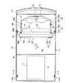
図1は、本発明に係る冷却装置の一実施形態が備えられる作業機械の一例であるホイールローダを示す側面図、図2は、図1に示すホイールローダの機械室内の状態を示す側面図、図3は、図2のIII−III断面図、図4は、図3に示すエアコンコンデンサおよびファンを回動させた状態を示す平面図、図5は、図3に示すエアコンコンデンサとトルコンクーラを一体化して回動させた状態を示す平面図である。 FIG. 1 is a side view showing a wheel loader that is an example of a work machine provided with an embodiment of a cooling device according to the present invention, and FIG. 2 is a side view showing a state of a machine room of the wheel loader shown in FIG. 3 is a cross-sectional view taken along the line III-III in FIG. 2, FIG. 4 is a plan view showing a state in which the air conditioner condenser and fan shown in FIG. 3 are rotated, and FIG. It is a top view which shows the state rotated integrally.
図2,3に示す本実施形態の冷却装置20は、例えば図1に示すホイールローダ1に備えられるものである。ホイールローダ1は、車体2と、この車体2の前部に結合された作業機4とを備えている。車体2は、その本体である車体フレーム3と、車体2のほぼ中央に配置され車体フレーム3に固定される運転室5と、運転室5の後方に配置され車体フレーム3に固定される機械室6とを備えている。
The
本実施形態である冷却装置20は、図2,3に示すように、ホイールローダ1の機械室6内に設置されている。機械室6内において、7はエンジンであり、8はエンジン7を設置するスペース9と冷却装置20を設置するスペース10とを仕切る隔壁である。また、11は機械室6の左側壁にヒンジ11aを介して左方向(矢印L方向)へ回動可能に取付けられ機械室6の左側部の開閉を可能にするメンテナンス用ドアであり、12は機械室6の右側壁にヒンジ12aを介して右方向(矢印R方向)へ回動可能に取付けられ機械室6の右側部の開閉を可能にするメンテナンス用ドアである。13は、機械室6の後端に形成された開口部15を覆う開閉カバーである。この開閉カバー13は、機械室6の上板6aに上方向へ回動可能に取付けられており、これにより、機械室6の後端を開閉できるようになっている。
The
本実施形態である冷却装置20は、空気を流動させるファン21と、このファン21が流動させた空気により冷却される複数の熱交換器、例えばインタークーラ31、オイルクーラ24、ラジエータ25、トルコンクーラ29、エアコンコンデンサ27とを備えている。
The
オイルクーラ24とラジエータ25は、図3に示すように、空気の流動方向(矢印A方向)に直交する方向、例えばホイールローダ1の左右方向に沿って並列に配置してある。インタークーラ31とトルコンクーラ29は、図2に示すように、オイルクーラ24およびラジエータ25の前面側において、空気の流動方向(矢印A方向)に直交する方向、例えばホイールローダ1の上下方向に沿って並列に配置してある。
As shown in FIG. 3, the
トルコンクーラ29の前面側には、図2,3に示すように、エアコンコンデンサ27を配置してある。つまり、冷却装置20では、オイルクーラ24およびラジエータ25のそれぞれと、エアコンコンデンサ27と、トルコンクーラ29とを空気の流動方向(矢印A方向)に沿って直列に配置してある。なお、エアコンコンデンサ27以外の熱交換器、すなわちオイルクーラ24、ラジエータ25、トルコンクーラ29により暖められた空気の温度は、エアコンコンデンサ27を冷却するには高すぎるので、エアコンコンデンサ27は、トルコンクーラ29、オイルクーラ24およびラジエータ25のいずれの熱交換器よりも空気の流れの上流に配置してある。
As shown in FIGS. 2 and 3, an
また、ファン21は、オイルクーラ24およびラジエータ25の後方に配置してある。このファン21は、モータ22により前記矢印A方向へ空気を流動させるように駆動される。
The
また、冷却装置20では、隣接する熱交換器の少なくとも一方を回動可能に設けてある。例えば、オイルクーラ24およびラジエータ25を固定し、これらのオイルクーラ24およびラジエータ25に隣接するトルコンクーラ29をそれらに対して回動可能に設け、さらに、トルコンクーラ29に隣接するエアコンコンデンサ27をトルコンクーラ29に対して回動可能に設けてある。具体的には、車体フレーム3に固定した枠体26にオイルクーラ24およびラジエータ25を取付け、この枠体26にヒンジ30aを介してトルコンクーラ29が取付けられたトルコンクーラ用フレーム30を取付け、このフレーム30にヒンジ28aを介してエアコンコンデンサ27が取付けられたエアコンコンデンサ用フレーム28が取付けてある。
Moreover, in the
また、インタークーラ31に取付けられたインタークーラ用フレーム32も、図示しないがヒンジを介して枠体26に取付けてある。
Further, the
また、ファン21およびモータ22を支持するファン用フレーム23も、ヒンジ23aを介して枠体26に取付けてある。
A
また、冷却装置20では、回動可能に設けられた熱交換器であるトルコンクーラ29およびエアコンコンデンサ27の回動中心、すなわちヒンジ28a,30aの回動中心を、ホイールローダ1の機械室6を形成する両側部の一方の側部付近、例えば右側部付近に設定してある。また、インタークーラ31の回動中心も、機械室6の右側部付近に設定してある。
Further, in the
また、冷却装置20は、それぞれが回動可能に設けられ互いに隣接する熱交換器、すなわちエアコンコンデンサ27とトルコンクーラ29を一組の熱交換器体として一体で回動可能にする一体化手段40を備えている。この一体化手段40は、エアコンコンデンサ用フレーム28の左端部に固定されるフック40aと、トルコンクーラ用フレーム30の左端部に固定されフック40aに係脱可能なラッチ40bとからなる。
In addition, the
また、冷却装置20は、トルコンクーラ29をオイルクーラ24およびラジエータ25に対して固定可能なトルコンクーラ用固定手段41を備えている。このトルコンクーラ用固定手段41は、トルコンクーラ用フレーム30の左側部に固定されるフック41aと、枠体26の左側部に固定されフック41aに係脱可能なラッチ41bとからなる。
The
また、冷却装置20は、ファン21をオイルクーラ24およびラジエータ25に対して固定可能にするファン用固定手段42を備えている。このファン用固定手段42は、ファン用フレーム23の左側部に固定されるフック42aと、枠体26の左側部に固定されフック42aに係脱可能なラッチ42bとからなる。
The
また、冷却装置20は、インタークーラ31をオイルクーラ24およびラジエータ25に対して固定可能にするインタークーラ用固定手段43を備えている。このインタークーラ用固定手段43は、インタークーラ用フレーム32の左側部に固定される図示しないフックと、枠体26の左端部に固定されフックに係脱可能な図示しないラッチとからなる。
In addition, the
このように構成した冷却装置20の清掃は、次のようにして行われる。
Cleaning of the
エアコンコンデンサ27の表面や、インタークーラ31の表面の清掃を行う場合は、作業者は、機械室6の左側部のメンテナンス用ドア11を開けたのち、隔壁8とエアコンコンデンサ27との間に形成されている空間内において、エアコンコンデンサ27の表面やインタークーラ31の表面の清掃を行う。
When cleaning the surface of the
エアコンコンデンサ27の裏面や、トルコンクーラ29の表面の清掃を行う場合、作業者は、一体化手段40のフック40aとラッチ40bの係合を解除する。つまり、トルコンクーラ29とエアコンコンデンサが一体化された状態を解除する。そして、エアコンコンデンサ27を、トルコンクーラ29から離間する方向、すなわち図4の矢印B方向へ回動させて、エアコンコンデンサ27とトルコンクーラ29との間に清掃を行うための空間を形成し、エアコンコンデンサ27の裏面やトルコンクーラ29の表面の清掃を行う。
When cleaning the back surface of the
トルコンクーラ29の裏面の清掃を行う場合、作業者は、トルコンクーラ用固定手段41のフック41aとラッチ41bの係合を解除する。つまり、トルコンクーラ29がオイルクーラ24およびラジエータ25に対して固定された状態を解除する。そして、トルコンクーラ29を、オイルクーラ24およびラジエータ25から離れる方向、すなわち矢印D方向へ回動させて、トルコンクーラ29と、オイルクーラ24およびラジエータ25のそれぞれとの間に清掃を行うための空間を形成し、トルコンクーラ29の裏面の清掃を行う。
When cleaning the back surface of the
インタークーラ31の裏面の清掃を行う場合、作業者は、インタークーラ用固定手段43の図示しないフックとラッチの係合を解除する。つまり、インタークーラ31がオイルクーラ24およびラジエータ25に対して固定された状態を解除する。そして、インタークーラ31を、オイルクーラ24およびラジエータ25から離間する方向へ回動させて、インタークーラ31とオイルクーラ24およびラジエータ25のそれぞれとの間に清掃を行うための空間を形成し、インタークーラ31の裏面の清掃を行う。
When cleaning the back surface of the
オイルクーラ24の表面や、ラジエータ25の表面の清掃を行う場合、作業者は、トルコンクーラ用固定手段41のフック41aとラッチ41bの係合を解除する。また、インタークーラ用固定手段43の図示しないフックとラッチの係合を解除する。
When cleaning the surface of the
次に、トルコンクーラ29を、オイルクーラ24およびラジエータ25から離れる方向、すなわち矢印D方向へ回動させて、トルコンクーラ29と、オイルクーラ24およびラジエータ25のそれぞれとの間に清掃を行うための空間を形成する。また、インタークーラ31を、オイルクーラ24およびラジエータ25から離間する方向へ回動させて、インタークーラ31とオイルクーラ24およびラジエータ25のそれぞれとの間に清掃を行うための空間を形成する。そして、オイルクーラ24の表面やラジエータ25の表面の清掃を行う。
Next, the
なお、エアコンコンデンサ27の裏面やトルコンクーラ29の表面の清掃を行わずに、オイルクーラ24の表面等の清掃を行う場合、一体化手段40のフック40aとラッチ40bの係合を解除せずに、すなわち、トルコンクーラ29とエアコンコンデンサ27とを一体化させた状態のまま、トルコンクーラ用固定手段41のフック41aとラッチ41bの係合を解除する。そして、エアコンコンデンサ27とトルコンクーラ29を一組の熱交換器体としてまとめて回動させ、トルコンクーラ29と、オイルクーラ24およびラジエータ25のそれぞれとの間に清掃を行うための空間を形成して、オイルクーラ24の表面等の清掃を行う。
When cleaning the surface of the
また、オイルクーラ24の裏面等の清掃を行う場合や、ファン21の清掃を行う場合、開閉カバー13を上方向へ回動させたのち、ファン用固定手段42のフック42aとラッチ42bの係合を解除する。つまり、ファン21がオイルクーラ24およびラジエータ25に対して固定された状態を解除する。そして、オイルクーラ24やラジエータ25から離れる方向、すなわち図4の矢印C方向へファン21を回動させて、ファン21とオイルクーラ24およびラジエータ25のそれぞれとの間に清掃を行うための空間を形成し、オイルクーラ24およびラジエータ25の裏面や、ファン21の清掃を行う。
Further, when cleaning the back surface of the
本実施形態である冷却装置20によれば、次の効果を得られる。
According to the
冷却装置20では、空気の流動方向に沿って直列に配置された3つの熱交換器のうちの隣接する熱交換器の組み合わせのすべてにおいて、すなわちエアコンコンデンサ27とトルコンクーラ29の組み合わせ、および、トルコンクーラ29とオイルクーラ24およびラジエータ25のそれぞれとの組み合わせにおいて、一方の熱交換器を清掃する場合に、清掃する熱交換器と、この熱交換器に隣接する他方の熱交換器の少なくとも一方を回動させて、清掃する熱交換器とこの熱交換器に隣接する他方の熱交換器との間に清掃を行うための空間を形成することができる。これにより、空気の流動方向に沿って直列に配置された熱交換器、すなわちエアコンコンデンサ27、トルコンクーラ29、オイルクーラ24およびラジエータ25のすべてに対して清掃を行うことができ、したがって、清掃性の向上に貢献できる。
In the
また、冷却装置20では、ファン21を回動可能に設けてあるので、オイルクーラ24の裏面やラジエータ25の裏面の清掃を行うことでき、この点でも、清掃性の向上に貢献できる。
Further, in the
また、冷却装置20では、回動可能に設けた熱交換器、すなわちエアコンコンデンサ27、トルコンクーラ29およびインタークーラ31のすべての回動中心を、ホイールローダ1の機械室6の右側部付近に設定した。これにより、機械室6の左側方から、すべての熱交換器に対する清掃作業を行うことができ、したがって、清掃作業の能率の向上に貢献できる。
Further, in the
また、冷却装置20では、隣接する熱交換器の両方、例えばエアコンコンデンサ27とトルコンクーラ29のそれぞれを回動可能に設け、これらエアコンコンデンサ27とトルコンクーラ29を一体化可能な一体化手段40を備えている。これにより、エアコンコンデンサ27とトルコンクーラ29とを一組の熱交換器体としてまとめて回動させることができ、この点でも、清掃作業の能率の向上に貢献できる。
Further, in the
なお、冷却装置20は、空気の流動方向に沿って直列に配置する熱交換器の数を3つにした例であったが、本発明はこれに限るものではなく、4つ以上でもよい。
The
また、冷却装置20は、空気の流動方向に沿って直列に配置した3つの熱交換器のうちの隣接する熱交換器のすべての組み合わせにおける少なくとも一方の熱交換器を回動可能に設けた例として、オイルクーラ24とラジエータ25を固定し、これらオイルクーラ24およびラジエータ25に隣接するトルコンクーラ29を回動可能に設け、このトルコンクーラ29に隣接するエアコンコンデンサ27を回動可能に設けたものである。しかし、本発明はこれに限るものではない。例えば、エアコンコンデンサ27を固定し、このエアコンコンデンサ27に隣接するトルコンクーラ29を回動可能に設け、このトルコンクーラ29に隣接するオイルクーラ24およびラジエータ25を回動可能に設けてもよい。また、エアコンコンデンサ27を回動可能に設け、このエアコンコンデンサ27に隣接するトルコンクーラ29を固定し、このトルコンクーラ29に隣接するオイルクーラ24およびラジエータ25を回動可能に設けてもよい。また、すべての熱交換器を回動可能に設けてもよい。
Moreover, the
また、冷却装置20では、オイルクーラ24およびラジエータ25の後方にファン21を配置した例であるが、本発明はこれに限るものではなく、エアコンコンデンサ27の前方にファン21を配置してもよい。この場合ファン21は、エンジン7により駆動してもよい。
In the
1 ホイールローダ
2 車体
3 車体フレーム
6 機械室
11 メンテナンス用ドア
12 メンテナンス用ドア
13 開閉カバー
15 開口部
20 冷却装置
21 ファン
22 モータ
23 ファン用フレーム
23a ヒンジ
24 オイルクーラ
25 ラジエータ
26 枠体
27 エアコンコンデンサ
28 エアコンコンデンサ用フレーム
28a ヒンジ
29 トルコンクーラ
30 トルコンクーラ用フレーム
30a ヒンジ
31 インタークーラ
32 インタークーラ用フレーム
40 一体化手段
41 トルコンクーラ用固定手段
42 ファン用固定手段
43 インタークーラ用固定手段
DESCRIPTION OF SYMBOLS 1
Claims (3)
前記3つ以上の熱交換器のうち、隣接する熱交換器同士の少なくとも一方は他方に対して回動可能に設け、
回動可能に設けた2つ以上の熱交換器のうち、連続して並ぶ熱交換器により一組の熱交換器体を形成し、
前記熱交換器体をこれに隣接する熱交換器に対し回動可能な状態を維持しつつ、前記熱交換器体を構成する熱交換器を一体化する一体化手段を設け、
前記回動可能に設けた熱交換器を、回転不能に固定可能な固定手段を設け、
前記作業機械の機械室を構成する左右両側部のうちの一方の側部であって、その機械室を開閉するメンテナンス用ドア側とは反対側の側部付近に、前記回動可能に設けた熱交換器の回動中心と前記熱交換器体の回動中心とを設定し、
前記機械室の左右両側部のうちの他方の側部であって、前記メンテナンス用ドア側の側部付近に前記一体化手段および前記固定手段を設けた
ことを特徴とする作業機械の冷却装置。 In a cooling device for a work machine, comprising: a fan for flowing air; and three or more heat exchangers arranged in series along the air flow direction,
Among the three or more heat exchangers, at least one of adjacent heat exchangers is provided to be rotatable with respect to the other,
Of two or more heat exchangers provided so as to be rotatable, a set of heat exchanger bodies is formed by heat exchangers arranged in series,
An integrated means for integrating the heat exchangers constituting the heat exchanger body is provided while maintaining a state in which the heat exchanger body is rotatable with respect to the heat exchanger adjacent thereto,
A fixing means capable of fixing the heat exchanger provided so as to be non-rotatable is provided,
A one side of the right and left side portions constituting the machine room of the working machine, the maintenance door for opening and closing the machine room near the side of the opposite side, provided to be the rotation Set the rotation center of the heat exchanger and the rotation center of the heat exchanger body,
A cooling device for a working machine, characterized in that the integration means and the fixing means are provided on the other side of the left and right sides of the machine room and in the vicinity of the side on the maintenance door side.
前記一体化手段は、前記熱交換器体を構成する熱交換器において隣接する熱交換器のうちの一方に固定されたフックと、他方に固定されて前記フックに係脱可能なラッチとからなる
ことを特徴とする作業機械の冷却装置。 In the invention of claim 1 ,
The integration means includes a hook fixed to one of adjacent heat exchangers in a heat exchanger constituting the heat exchanger body, and a latch fixed to the other and detachable from the hook. A cooling device for a work machine.
前記ファンを、前記熱交換器に対して回動可能に設けた
ことを特徴とする作業機械の冷却装置。 In the invention of claim 1 or 2,
A cooling device for a working machine, wherein the fan is rotatably provided with respect to the heat exchanger.
Priority Applications (1)
| Application Number | Priority Date | Filing Date | Title |
|---|---|---|---|
| JP2004380083A JP4685437B2 (en) | 2004-12-28 | 2004-12-28 | Work machine cooling system |
Applications Claiming Priority (1)
| Application Number | Priority Date | Filing Date | Title |
|---|---|---|---|
| JP2004380083A JP4685437B2 (en) | 2004-12-28 | 2004-12-28 | Work machine cooling system |
Publications (2)
| Publication Number | Publication Date |
|---|---|
| JP2006183399A JP2006183399A (en) | 2006-07-13 |
| JP4685437B2 true JP4685437B2 (en) | 2011-05-18 |
Family
ID=36736705
Family Applications (1)
| Application Number | Title | Priority Date | Filing Date |
|---|---|---|---|
| JP2004380083A Expired - Fee Related JP4685437B2 (en) | 2004-12-28 | 2004-12-28 | Work machine cooling system |
Country Status (1)
| Country | Link |
|---|---|
| JP (1) | JP4685437B2 (en) |
Families Citing this family (10)
| Publication number | Priority date | Publication date | Assignee | Title |
|---|---|---|---|---|
| JP2008121292A (en) * | 2006-11-13 | 2008-05-29 | Hitachi Constr Mach Co Ltd | Construction equipment |
| US9441892B2 (en) * | 2006-12-11 | 2016-09-13 | Deere & Company | Stacked heat exchanger system with swing-out heat exchangers |
| KR101370097B1 (en) | 2009-09-30 | 2014-03-04 | 현대중공업 주식회사 | Cooling system for wheel loader |
| US20110277961A1 (en) * | 2010-05-13 | 2011-11-17 | Knepper Anthony J | Vehicle Cooling System |
| US8960342B2 (en) | 2011-02-22 | 2015-02-24 | Deere & Company | Swing-out coolers and cooling fans |
| US8672071B2 (en) | 2011-09-21 | 2014-03-18 | Deere & Company | Fluid cooler arrangement for a cooling package in a work vehicle |
| JP5205536B1 (en) | 2012-06-28 | 2013-06-05 | 株式会社小松製作所 | Wheel loader |
| EP3366899B1 (en) | 2016-12-28 | 2019-11-06 | Komatsu Ltd. | Utility vehicle, and method for adjusting position of movable part of utility vehicle |
| JP6911524B2 (en) * | 2017-05-22 | 2021-07-28 | コベルコ建機株式会社 | Construction machinery cooling system |
| CN115489296A (en) * | 2021-06-17 | 2022-12-20 | 湖南道依茨动力有限公司 | Radiator and engineering vehicle |
Citations (3)
| Publication number | Priority date | Publication date | Assignee | Title |
|---|---|---|---|---|
| JP2000120437A (en) * | 1998-10-16 | 2000-04-25 | Komatsu Ltd | Cooling fan driving device |
| JP2002302969A (en) * | 2001-04-05 | 2002-10-18 | Shin Caterpillar Mitsubishi Ltd | Construction machine and cooling air duct |
| JP2002371844A (en) * | 2001-06-13 | 2002-12-26 | Shin Caterpillar Mitsubishi Ltd | Cooling package for construction machine |
-
2004
- 2004-12-28 JP JP2004380083A patent/JP4685437B2/en not_active Expired - Fee Related
Patent Citations (3)
| Publication number | Priority date | Publication date | Assignee | Title |
|---|---|---|---|---|
| JP2000120437A (en) * | 1998-10-16 | 2000-04-25 | Komatsu Ltd | Cooling fan driving device |
| JP2002302969A (en) * | 2001-04-05 | 2002-10-18 | Shin Caterpillar Mitsubishi Ltd | Construction machine and cooling air duct |
| JP2002371844A (en) * | 2001-06-13 | 2002-12-26 | Shin Caterpillar Mitsubishi Ltd | Cooling package for construction machine |
Also Published As
| Publication number | Publication date |
|---|---|
| JP2006183399A (en) | 2006-07-13 |
Similar Documents
| Publication | Publication Date | Title |
|---|---|---|
| JP4880779B2 (en) | Construction machinery | |
| JP5074638B2 (en) | Wheel loader | |
| JP5048718B2 (en) | Working vehicle cab | |
| JP4685437B2 (en) | Work machine cooling system | |
| JP2013002170A (en) | Hydraulic shovel | |
| US9708792B2 (en) | Construction machine having cooling function | |
| JP2006170108A (en) | Cooling device of working machine | |
| JP6507986B2 (en) | Construction machinery | |
| JP5507602B2 (en) | Vehicle outside air introduction structure | |
| CN205086672U (en) | Vehicle | |
| JP6597154B2 (en) | Construction machinery | |
| JP4390045B2 (en) | Construction machine cooling system | |
| JP5451669B2 (en) | Work machine | |
| JP6338821B2 (en) | Construction machinery | |
| JPWO2004099581A1 (en) | Cooling device for work vehicle | |
| JP2004169518A (en) | Cooling device for construction machinery | |
| JP7060659B2 (en) | Body front structure | |
| JPH07127097A (en) | Construction machine | |
| JP6058448B2 (en) | Construction machinery | |
| JP4051191B2 (en) | Air conditioner for vehicles | |
| JPH11254976A (en) | Noise reducing device for construction machine and cover and exhaust part used for this device | |
| JP3593086B2 (en) | Vehicle air conditioner | |
| JP2010185275A (en) | Engine room structure of working machine | |
| JP3759485B2 (en) | EGR valve support structure for horizontal V engine | |
| US20080110201A1 (en) | Vehicle air conditioner |
Legal Events
| Date | Code | Title | Description |
|---|---|---|---|
| A711 | Notification of change in applicant |
Free format text: JAPANESE INTERMEDIATE CODE: A711 Effective date: 20060921 |
|
| A521 | Written amendment |
Free format text: JAPANESE INTERMEDIATE CODE: A821 Effective date: 20060921 |
|
| A621 | Written request for application examination |
Free format text: JAPANESE INTERMEDIATE CODE: A621 Effective date: 20070202 |
|
| A977 | Report on retrieval |
Free format text: JAPANESE INTERMEDIATE CODE: A971007 Effective date: 20081226 |
|
| A131 | Notification of reasons for refusal |
Free format text: JAPANESE INTERMEDIATE CODE: A131 Effective date: 20100105 |
|
| A521 | Written amendment |
Free format text: JAPANESE INTERMEDIATE CODE: A523 Effective date: 20100305 |
|
| A131 | Notification of reasons for refusal |
Free format text: JAPANESE INTERMEDIATE CODE: A131 Effective date: 20100713 |
|
| A521 | Written amendment |
Free format text: JAPANESE INTERMEDIATE CODE: A523 Effective date: 20100909 |
|
| A711 | Notification of change in applicant |
Free format text: JAPANESE INTERMEDIATE CODE: A712 Effective date: 20101210 |
|
| A521 | Written amendment |
Free format text: JAPANESE INTERMEDIATE CODE: A821 Effective date: 20101210 |
|
| TRDD | Decision of grant or rejection written | ||
| A01 | Written decision to grant a patent or to grant a registration (utility model) |
Free format text: JAPANESE INTERMEDIATE CODE: A01 Effective date: 20110201 |
|
| A01 | Written decision to grant a patent or to grant a registration (utility model) |
Free format text: JAPANESE INTERMEDIATE CODE: A01 |
|
| A61 | First payment of annual fees (during grant procedure) |
Free format text: JAPANESE INTERMEDIATE CODE: A61 Effective date: 20110210 |
|
| FPAY | Renewal fee payment (event date is renewal date of database) |
Free format text: PAYMENT UNTIL: 20140218 Year of fee payment: 3 |
|
| R150 | Certificate of patent or registration of utility model |
Ref document number: 4685437 Country of ref document: JP Free format text: JAPANESE INTERMEDIATE CODE: R150 Free format text: JAPANESE INTERMEDIATE CODE: R150 |
|
| S111 | Request for change of ownership or part of ownership |
Free format text: JAPANESE INTERMEDIATE CODE: R313111 |
|
| S531 | Written request for registration of change of domicile |
Free format text: JAPANESE INTERMEDIATE CODE: R313531 |
|
| R350 | Written notification of registration of transfer |
Free format text: JAPANESE INTERMEDIATE CODE: R350 |
|
| LAPS | Cancellation because of no payment of annual fees |