JP4678802B2 - Sliding contact surface member - Google Patents
Sliding contact surface member Download PDFInfo
- Publication number
- JP4678802B2 JP4678802B2 JP2000337444A JP2000337444A JP4678802B2 JP 4678802 B2 JP4678802 B2 JP 4678802B2 JP 2000337444 A JP2000337444 A JP 2000337444A JP 2000337444 A JP2000337444 A JP 2000337444A JP 4678802 B2 JP4678802 B2 JP 4678802B2
- Authority
- JP
- Japan
- Prior art keywords
- contact surface
- peripheral wall
- inner peripheral
- sliding contact
- honing
- Prior art date
- Legal status (The legal status is an assumption and is not a legal conclusion. Google has not performed a legal analysis and makes no representation as to the accuracy of the status listed.)
- Expired - Fee Related
Links
Images


Description
【0001】
【発明の属する技術分野】
本発明は、所定の部材が摺接する摺接面を有する有摺接面部材に関する。
【0002】
【従来の技術】
内燃機関用シリンダブロックに設けられたシリンダボア内では、ピストンおよび該ピストンに嵌合されたピストンリングが往復動作される。すなわち、シリンダボアの内周壁部には、ピストンおよびピストンリングの側周壁部が摺接する。
【0003】
この摺接は、両者の間に潤滑油が介在された状態で行われる。シリンダボアの内周壁部にピストンおよびピストンリングの側周壁部が摺接することに伴って発生した摩擦熱は、この潤滑油により除去される。すなわち、潤滑油で前記内周壁部および前記側周壁部が冷却されることにより、両者に焼き付きが生じることが回避される。
【0004】
このことから諒解されるように、潤滑油を介して所定の部材が摺接する摺接面を有する部材(以下、有摺接面部材という)においては、該摺接面が潤滑油保持能に優れていることが好ましい。この場合、摺接面に保持された潤滑油によって該摺接面が効率よく冷却され、したがって、焼き付きを確実に回避することができるからである。
【0005】
そこで、潤滑油が良好に保持されるように、摺接面が特定の形状に加工された部材が種々提案されている。その例としては、スカート部に条痕が形成された内燃機関用ピストン、内周壁部にプラトーホーニングが形成されたシリンダボアを有する内燃機関用シリンダブロック、超微細オイルポッドが形成されたローラベアリング、グルーブが形成されたエンジンメインベアリング等が挙げられる。これらは既に実用化されており、実際、摺接面の耐焼き付き性や疲労強度等が向上した部材として広く認識されるに至っている。
【0006】
【発明が解決しようとする課題】
潤滑油を良好に保持させるようにするためには、上記したように、摺接面に条痕やプラトーホーニング等を設けることにより該摺接面を粗くすればよい。これにより摺接面に多数の凹凸部が形成され、その結果、潤滑油が凹部に貯留されるようになる。すなわち、この場合、平滑な摺接面に比して多量の潤滑油が滞留されるようになるからである。
【0007】
しかしながら、摺接面が粗いほど摩擦抵抗が高くなる。したがって、例えば、シリンダボアであれば、ピストンおよびピストンリングを往復動作させる際に要する駆動力が大きくなる。このような事態が生じると、内燃機関を付勢するための燃料消費量が増加してしまうという不具合が惹起される。また、ピストンおよびピストンリングが摺接する際に発生する摩擦熱量が大きくなるので、焼き付きを招くことが懸念される。
【0008】
このように、潤滑油保持能の大小と摩擦抵抗の高低は、互いに相反するように上昇・低下してしまう。このため、潤滑油保持能に優れかつ摩擦抵抗が小さい摺接面を形成することは困難を極めている。
【0009】
本発明は上記した問題を解決するためになされたもので、潤滑剤保持能に優れるとともに所定の部材が摺接する際の摩擦抵抗が充分に低い摺接面を有する有摺接面部材を提供することを目的とする。
【0010】
【課題を解決するための手段】
前記の目的を達成するために、本発明は、所定の部材が潤滑剤を介して摺接する摺接面を有する有摺接面部材であって、
前記摺接面は、ホーニング加工によって形成された複数の凹部及び凸部が連なるうねりを有するホーニング加工面であり、
前記ホーニング加工面の前記うねりにおける十点平均粗さ、負荷長さ率および有効負荷粗さを複数箇所測定した際の平均値が、それぞれ、1μm以上5μm以下、55%以上98%以下、1μm以下であることを特徴とする。
【0011】
十点平均粗さ、負荷長さ率および有効負荷粗さが上記の範囲内である摺接面には、潤滑剤保持部として機能する凹部が多数存在する。このため、この摺接面は潤滑剤保持能に優れる。したがって、該摺接面が潤滑剤により確実に冷却されるので、焼き付きが生じることを回避することもできる。
【0012】
しかも、この場合、前記所定の部材が摺接する際の摩擦抵抗が充分に小さい。したがって、該部材が容易に摺動動作することができる。このため、該部材を摺接させるために多大な駆動力を要することがない。また、発生する摩擦熱量が小さくなるので、焼き付きが生じることが一層回避される。
【0013】
有摺接面部材の好適な例としては、内燃機関用シリンダブロックを挙げることができる。この場合、シリンダボアの内周壁部が摺接面となる。
【0014】
【発明の実施の形態】
以下、本発明に係る有摺接面部材につき好適な実施の形態を挙げ、添付の図面を参照して詳細に説明する。
【0015】
本実施の形態に係る有摺接面部材としての内燃機関用シリンダブロックの概略全体斜視図を図1に示す。この内燃機関用シリンダブロック10には6箇所のシリンダボア12a〜12fが設けられており、該シリンダボア12a〜12fの内部では図示しないピストンおよび該ピストンに嵌合されたピストンリングが往復動作される。すなわち、シリンダボア12a〜12fの内周壁部14a〜14fは、ピストンおよびピストンリングの側周壁部が摺接する摺接面である。
【0016】
このうち、内周壁部14aの表面を拡大して図2に示す。この図2に示されるように、内周壁部14aの表面は微視的には平坦ではなく、複数の凹部16と凸部18とが互いに連なってなるうねり20を多数有する。潤滑剤である潤滑油は、凹部16に貯留される。すなわち、凹部16はオイルピットとして機能する。
【0017】
そして、うねり20は、基準長さ0.8mm、評価長さ4mmにおける十点平均粗さ(以下、Rzとも表記する)、基準長さ0.8mm、評価長さ4mm、切断レベル20%における負荷長さ率(以下、tpとも表記する)、基準長さ0.8mm、評価長さ4mmにおける有効負荷粗さ(以下、Rkとも表記する)を複数箇所測定した際の平均値が後述する範囲内となるように形成されている。
【0018】
ここで、Rz、tpおよびRkの定義を示すとともに、その範囲について説明する。
【0019】
まず、十点平均粗さとは、図3に示すように、うねり20を表す粗さ曲線CVから平均線の方向に基準長さだけ抜き取り、この抜き取り部分における最も高い凸部18aから5番目に高い凸部18bまでの標高(平均線から山頂までの距離Yp1〜Yp5)の絶対値の平均値と、最も低い凹部16aから5番目に低い凹部16bまでの深さ(平均線から谷底までの距離Yv1〜Yv5)の絶対値の平均値の和である。すなわち、Rzは、以下の(1)式により求められる。
【0020】
【数1】

なお、上記したように、本実施の形態においては基準長さを0.8mmとし、かつ評価長さを4mmとしている。また、平均線とは、基準長さ0.8mmにおける各凹部16の深さおよび各凸部18の標高に基づいて最小自乗法により求められた直線である。
【0022】
うねり20は、Rzが1μm以上5μm以下となるように形成されている。Rzが1μm未満であると、凹部16が浅くなるので潤滑油を充分に貯留することができなくなる。すなわち、内周壁部14aが潤滑油保持能に乏しくなる。また、5μmを超えると、内周壁部14aの摩擦抵抗が高くなる。
【0023】
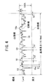
次に、負荷長さ率とは、図4に示すように、粗さ曲線CVから基準長さだけ抜き取り、この抜き取り部分における最も高い凸部18aを通る直線(山頂線)に対して平行な切断レベルで切断したときに得られる切断長さ(図4におけるb1、b2、…bi、…bn)の総和の基準長さに対する比を百分率で表したものである。本実施の形態では基準長さが0.8mmであるので、tpは以下の(2)式により求められる。
【0024】
tp={(b1+b2+…+bi+…+bn)/0.8}×100 …(2)
【0025】
ここで、本実施の形態では、切断レベルを20%としている。すなわち、図4における切断線は、山頂線と、最も深い凹部16aを通って平均線に平行な谷底線との間の距離を100%とするとき、その20%に相当する位置から山頂線および谷底線に対して平行に引かれた直線である。
【0026】
うねり20は、tpが55%〜98%の範囲内となるように形成されている。tpが55%未満であると、内周壁部14aの摩擦抵抗が大きくなる。また、98%を超えると、凹部16の数が少なくなる。すなわち、オイルピットの数が少なくなるので、内周壁部14aが潤滑油保持能に乏しくなる。
【0027】
また、有効負荷粗さとは、図5に示される直線Lとtp=0%および100%(縦軸)との各交点であるA点とB点との間の距離である。ここで、直線Lは、横軸をtpとする負荷曲線V上でtp値の差が40%となるC点およびD点を通る直線の中で最も傾きが小さい直線である。なお、負荷曲線Vは、各凹部16の深さおよび各凸部18の標高の分布に基づいて求められる。
【0028】
うねり20は、Rkが1μm以下となるように形成されている。Rkが1μmよりも大きいと、内周壁部14aの摩擦抵抗が高くなるからである。
【0029】
一例として、Rz=1.18μm、tp=95.1%、Rk=0.15μmである粗さ曲線CV1、Rz=2.22μm、tp=84.6%、Rk=0.48μmである粗さ曲線CV2、およびRz=2.88μm、tp=55.1%、Rk=0.94μmである粗さ曲線CV3を図6〜図8にそれぞれ示す。これら図6〜図8から、摺接面は、RzおよびRkが小さくかつtpが大きいほど平滑になり、一方、RzおよびRkが大きくかつtpが小さいほど粗くなることが諒解される。
【0030】
これら粗さ曲線CV1〜CV3は、うねり20、換言すれば、内周壁部14aの表面の状態を表す。すなわち、図6に示される状態に近づくほど摩擦抵抗は低減するが、オイルピット(凹部16)の数が減少するので潤滑油保持能が低減してしまう。また、図8に示される状態に近づくほど潤滑油保持能が向上するが、摩擦抵抗が上昇してしまう。そこで、Rz、tpおよびRkを上記範囲内に規定することにより、潤滑油保持能に優れ、かつ摩擦抵抗が充分に低い内周壁部14aを得ることができる。なお、本実施の形態においては、全てのうねり20におけるRz、tpおよびRkが上記範囲内である必要は特になく、複数個のうねり20についてRz、tpおよびRkを測定し、その平均値が上記範囲内であればよい。
【0031】
勿論、残余のシリンダボア12b〜12f(図1参照)の内周壁部14b〜14fにおいても、内周壁部14aと同様にRz、tpおよびRkが上記範囲内に規定されている。このようなシリンダボア12a〜12fを有する内燃機関用シリンダブロック10においては、該シリンダボア12a〜12f内でピストンおよびピストンリングを容易に往復動作させることができる。該シリンダボア12a〜12fの内周壁部14a〜14fの摩擦抵抗が低いからである。したがって、燃料消費量を低減することができる。しかも、摩擦熱量が小さくなるので、焼き付きが発生することを回避することもできる。
【0032】
また、内周壁部14a〜14fが潤滑油保持能に優れているので、焼き付きが発生することが一層回避される。
【0033】
Rz、tpおよびRkが上記範囲内に規定されたうねり20を有する内周壁部14a〜14fは、例えば、図9に示すホーニング加工装置30を用いることにより形成することができる。
【0034】
このホーニング加工装置30の構成につき、図9を参照して概略説明する。
【0035】
ホーニング加工装置30は、シリンダボア12a〜12f内に挿入されるホーニングヘッド32と、該ホーニングヘッド32に拡張力を与えるための第1油圧シリンダ34と、この拡張力を制御する制御回路36と、第1油圧シリンダ34を収容した回転軸部38と、該回転軸部38を昇降動作させるための第2油圧シリンダ40とを備える。
【0036】
ホーニングヘッド32には、4個の砥石42a〜42dが互いに90°ずつ離間して固定されている。また、ホーニングヘッド32と回転軸部38とは互いに連結されており、したがって、回転軸部38が回転動作されることに追従してホーニングヘッド32も回転動作する。なお、後述するように、砥石42a〜42dは、粗加工と仕上げ加工において互いに異なるものが選定される。
【0037】
ホーニングヘッド32は、拡径または縮径させることが可能な円柱体である。すなわち、第1油圧シリンダ34に油圧が加えられた場合、この油圧は図示しない油路を介してホーニングヘッド32に伝達され、その結果、ホーニングヘッド32が拡径されて砥石42a〜42dがシリンダボア12a〜12fの内周壁部14a〜14fに当接する。
【0038】
第1油圧シリンダ34に作用する油圧の増減は、該第1油圧シリンダ34と油源44とを連結する油路46に介装された減圧バルブ48によって遂行される。後述するように、この油圧は制御回路36によって制御される。
【0039】
回転軸部38には、第2油圧シリンダ40のピストンロッド50が連結されている。このピストンロッド50には変速歯車52が嵌合されており、該変速歯車52には、図示しないモータが有する回転軸に嵌合された図示しない歯車が噛合されている。
【0040】
第2油圧シリンダ40のシリンダチューブ54は、支持盤56により支持されている。この支持盤56にはガイドバー58が位置決め固定されており、該ガイドバー58のバー部60は連結盤62に設けられた貫通孔(図示せず)に嵌合されている。また、連結盤62は、図示しないベアリングを介して回転軸部38の側周壁部に嵌合されている。
【0041】
そして、第2油圧シリンダ40のシリンダチューブ54において、ピストンロッド50の油圧受部64で区分される第1室66および第2室68には、切換バルブ70が介装された油路72a、72bを介して油源74がそれぞれ接続されている。この油源74により、ピストンロッド50の昇降動作が遂行される。なお、油源74と制御回路36とは、ケーブル76を介して互いに電気的に接続されている。
【0042】
このようなホーニング加工装置30を使用し、粗加工と仕上げ加工とで砥石を変更してシリンダボア12a〜12fの内周壁部14a〜14fを研磨加工することにより、該内周壁部14a〜14fにRz、tpおよびRkが上記した範囲内であるうねり20を形成することができる。
【0043】
具体的には、以下のようである。
【0044】
まず、粗加工および仕上げ加工を行って内周壁部14a〜14fを研磨加工する。この際、ホーニングヘッド32を拡径する油圧、すなわち、第1油圧シリンダ34に与える油圧を種々変化させて仕上げ加工を行い、形成されたうねり20につきRz、tpおよびRkを測定し、仕上げ加工時の油圧等と、Rz、tpおよびRkとの相関関係を調査しておく。
【0045】
実際の研磨加工を行うに際しては、まず、ホーニングヘッド32に粒度が170〜325メッシュのメタルボンドダイヤモンド砥石を装着した後、制御回路36に「起動」の命令を与える。これにより切換バルブ70内の油源74から第2油圧シリンダ40への流路が開き、第2油圧シリンダ40のシリンダチューブ54の第2室68内に作動油が導入される。これに伴い該第2室68内の油圧が上昇し、その結果、ピストンロッド50が下降動作してホーニングヘッド32が例えばシリンダボア12a内に挿入される。この際、回転軸部38は、連結盤62を介してガイドバー58のバー部60により案内される。
【0046】
勿論、制御回路36は、ホーニングヘッド32が所定の位置に到達した際にピストンロッド50の下降動作を停止させる。すなわち、制御回路36は、ケーブル76を介して切換バルブ70に制御信号を送ることにより該切換バルブ70を閉止する。
【0047】
次いで、制御回路36の制御作用下に減圧バルブ48が開かれ、その結果、ホーニングヘッド32が拡径されてメタルボンドダイヤモンド砥石がシリンダボア12aの内周壁部14aに当接する。
【0048】
この状態で、制御回路36の制御作用下に図示しないモータが付勢される。これに伴い該モータが有する回転軸が回転動作を開始することに追従して変速歯車52が回転動作し、最終的に回転軸部38が回転動作するに至る。なお、回転軸部38と連結盤62との間には図示しないベアリングが介在されているので、連結盤62およびガイドバー58が回転動作することはない。
【0049】
回転軸部38が回転動作することにより、メタルボンドダイヤモンド砥石が内周壁部14aに摺接する。これにより該内周壁部14aが粗く研磨されるに至る(粗加工)。
【0050】
所定時間が経過した後、制御回路36は、第1油圧シリンダ34に作用する油圧が低下するように減圧バルブ48を制御する。これに伴いホーニングヘッド32が縮径してメタルボンドダイヤモンド砥石が内周壁部14aから離間する。
【0051】
そして、切換バルブ70内の第2室68から油源74への流路および油源74から第1室66への流路が開き、その結果、作動油が第1室66内に導入されるとともに第2室68から導出される。これに伴い該第1室66内の油圧が第2室68内に比して高くなり、したがって、ピストンロッド50が上昇動作してホーニングヘッド32がシリンダボア12aから離脱する。この際にも、回転軸部38は、連結盤62を介してガイドバー58のバー部60より案内される。
【0052】
この時点でホーニング加工装置30の運転を一旦停止して、砥石を仕上げ加工用のものに変更する。この場合、仕上げ加工用砥石としては、粒度が2000〜8000メッシュの砥石、好ましくは3000メッシュのビトリファイドボンド砥石が選定される。
【0053】
この砥石における砥粒としては、特に限定されるものではないが、仕上げ加工時に不水溶性クーラントを使用する必要がなく、したがって、研磨加工に要するコストを低廉化できることから、ダイヤモンドであることが好ましい。この場合、不水溶性クーラントを処理する必要がないので、その処理コストが不要となるからである。
【0054】
次に、ホーニングヘッド32を拡径する油圧等の加工条件パラメータを、Rzが基準長さ0.8mm、評価長さ4mmにおいて1μm〜5μm、tpが基準長さ0.8mm、評価長さ4mm、切断レベル20%において55%〜98%、Rkが基準長さ0.8mm、評価長さ4mmにおいて1μm以下であるうねり20が内周壁部14aに形成される範囲内の値で制御回路36に入力する。油圧は、例えば、1MPa(10kgf/cm2)程度とすればよい。
【0055】
その後、制御回路36に再び「起動」の命令を与える。これにより上記と同様にしてピストンロッド50が下降動作し、ホーニングヘッド32がシリンダボア12a内に挿入される。
【0056】
そして、制御回路36は、ホーニングヘッド32に供給される油圧が入力された油圧となるように減圧バルブ48の開度を調整する。すなわち、ホーニングヘッド32はこの油圧(拡張力)で拡径され、その結果、ビトリファイドボンド砥石が内周壁部14aに当接する。以下、ビトリファイドボンド砥石により上記と同様にして内周壁部14aの仕上げ加工が遂行される。
【0057】
ビトリファイドボンド砥石では、砥粒と砥粒とが軟質なビトリファイドによって互いに結合されている。したがって、砥粒は、仕上げ加工が遂行される最中に比較的容易に脱落する。換言すれば、ビトリファイドボンド砥石は仕上げ加工が進行するにつれて摩耗するので、一定量を超えて内周壁部14aを研磨加工することができなくなる。要するに、内周壁部14aの研磨量は一定値で飽和する。このように、仕上げ加工用砥石としてビトリファイドボンド砥石を採用することにより、内周壁部14aが必要量を超えて研磨されることを確実に回避することができる。
【0058】
しかも、上記したように、ホーニングヘッド32は、制御回路36に入力された油圧、すなわち、Rz、tpおよびRkが上記した範囲内であるうねり20が形成される油圧(拡張力)で拡径されている。したがって、ビトリファイドボンド砥石の研削力が被削材の研削抵抗と等しくなり、内周壁部14aを研磨加工することができなくなった際には、該内周壁部14aには、Rz、tpおよびRkが制御回路36に入力された値であるうねり20が形成されている。
【0059】
このように、仕上げ加工用砥石としてビトリファイドボンド砥石を使用することにより、内周壁部14aにRz、tpおよびRkが上記した範囲内であるうねり20を確実に形成することができる。
【0060】
以下、同様にして残余のシリンダボア12b〜12fの内周壁部14b〜14fをホーニング加工することにより、Rz、tpおよびRkが上記した範囲内であるうねり20が内周壁部14b〜14fにも形成される。
【0061】
なお、上記した実施の形態においては、有摺接面部材として内燃機関用シリンダブロック10を例示して説明したが、特にこれに限定されるものではない。例えば、該内燃機関用シリンダブロック10のシリンダボア12a〜12f内を往復動作するピストンおよび該ピストンに嵌合されたピストンリングであってもよい。この場合、該ピストンおよびピストンリングの側周壁部が摺接面となる。
【0062】
ピストンおよびピストンリングの側周壁部の研磨加工は、例えば、高圧水とともに噴射されたガラスビーズをピストンおよびピストンリングの側周壁部に衝突させることにより行うことができる。この場合、Rz、tpおよびRkは、ガラスビーズの直径や高圧水の噴射圧力を設定することにより制御すればよい。同様にして、クランクシャフトのクランクピン部やジャーナル部、またはベアリング等も研磨加工することが可能である。
【0063】
【発明の効果】
以上説明したように、本発明に係る有摺接面部材によれば、その摺接面における十点平均粗さ、負荷長さ率および有効負荷粗さの平均値が所定の範囲内に設定されている。このため、該摺接面が潤滑剤保持能に優れるとともに摩擦抵抗が充分に小さいものとなる。したがって、焼き付きが生じることを確実に回避することができ、かつ所定の部材を該摺接面上で容易に摺動動作させることができるという効果が達成される。
【0064】
有摺接面部材の好適な例としては、内燃機関用シリンダブロックを挙げることができる。この内燃機関用シリンダブロックにおいては、シリンダボア内部でピストンおよびピストンリングを容易に往復動作させることができる。このため、内燃機関を付勢するための燃料消費量を低減することができる。
【図面の簡単な説明】
【図1】本実施の形態に係る有摺接面部材である内燃機関用シリンダブロックの概略全体斜視図である。
【図2】図1の内燃機関用シリンダブロックに設けられたシリンダボアの内周壁部(摺接面)の要部拡大図である。
【図3】十点平均粗さの定義を説明する説明図である。
【図4】負荷長さ率の定義を説明する説明図である。
【図5】有効負荷粗さの定義を説明する説明図である。
【図6】Rz、tpおよびRkの値と粗さ曲線との関係を説明する説明図である。
【図7】Rz、tpおよびRkの値と粗さ曲線との関係を説明する説明図である。
【図8】Rz、tpおよびRkの値と粗さ曲線との関係を説明する説明図である。
【図9】内周壁部をホーニング加工するために使用されるホーニング加工装置の一部断面概略正面図である。
【符号の説明】
10…内燃機関用シリンダブロック(有摺接面部材)
12a〜12f…シリンダボア 14a〜14f…内周壁部(摺接面)
16、16a、16b…凹部 18、18a、18b…凸部
20…うねり 30…ホーニング加工装置
32…ホーニングヘッド 36…制御回路
38…回転軸部 42a〜42d…砥石
44、74…油源 46、72a、72b…油路
CV、CV1、CV2、CV3…粗さ曲線
V…負荷曲線[0001]
BACKGROUND OF THE INVENTION
The present invention relates to a slidable contact surface member having a slidable contact surface with which a predetermined member is slidably contacted.
[0002]
[Prior art]
In the cylinder bore provided in the cylinder block for the internal combustion engine, the piston and the piston ring fitted to the piston are reciprocated. That is, the side peripheral wall portions of the piston and the piston ring are in sliding contact with the inner peripheral wall portion of the cylinder bore.
[0003]
This sliding contact is performed in a state in which lubricating oil is interposed between the two. The frictional heat generated when the piston and the side peripheral wall portion of the piston ring come into sliding contact with the inner peripheral wall portion of the cylinder bore is removed by this lubricating oil. That is, the inner peripheral wall portion and the side peripheral wall portion are cooled by the lubricating oil, thereby avoiding the occurrence of seizure.
[0004]
As can be understood from this, in a member having a slidable contact surface (hereinafter referred to as a slidable contact surface member) with which a predetermined member is slidably contacted via the lubricating oil, the slidable contact surface has an excellent lubricating oil retaining ability. It is preferable. In this case, the sliding contact surface is efficiently cooled by the lubricating oil held on the sliding contact surface, and therefore seizure can be reliably avoided.
[0005]
Accordingly, various members have been proposed in which the sliding contact surface is processed into a specific shape so that the lubricating oil is well retained. Examples include pistons for internal combustion engines with streaks formed on the skirt, cylinder blocks for internal combustion engines having cylinder bores with plateau honing formed on the inner peripheral wall, roller bearings and grooves formed with ultrafine oil pods, and grooves. The engine main bearing etc. in which is formed. These have already been put to practical use, and in fact, have come to be widely recognized as members having improved seizure resistance, fatigue strength, and the like on the sliding contact surface.
[0006]
[Problems to be solved by the invention]
In order to hold the lubricating oil satisfactorily, the sliding contact surface may be roughened by providing streaks, plateau honing, etc. on the sliding contact surface as described above. As a result, a large number of concave and convex portions are formed on the sliding contact surface, and as a result, the lubricating oil is stored in the concave portions. That is, in this case, a large amount of lubricating oil is retained as compared with a smooth sliding contact surface.
[0007]
However, the rougher the sliding surface, the higher the frictional resistance. Therefore, for example, in the case of a cylinder bore, the driving force required for reciprocating the piston and the piston ring increases. When such a situation occurs, there is a problem that the amount of fuel consumption for energizing the internal combustion engine increases. Further, since the amount of frictional heat generated when the piston and the piston ring are in sliding contact with each other increases, there is a concern that seizure will be caused.
[0008]
As described above, the magnitude of the lubricating oil retention ability and the level of frictional resistance rise and fall in a mutually contradictory manner. For this reason, it is extremely difficult to form a slidable contact surface that has excellent lubricating oil retention ability and low frictional resistance.
[0009]
The present invention has been made to solve the above-described problems, and provides a slidable contact surface member having a slidable contact surface that is excellent in lubricant retention capability and has a sufficiently low frictional resistance when a predetermined member is in slidable contact. For the purpose.
[0010]
[Means for Solving the Problems]
In order to achieve the above object, the present invention provides a sliding contact surface member having a sliding contact surface with which a predetermined member is in sliding contact with a lubricant,
The sliding contact surface is a honing surface for have a plurality of recesses and swell convex portions are contiguously formed by honing,
The average values when measuring the ten-point average roughness, load length ratio, and effective load roughness of the honing-processed surface at a plurality of locations are 1 μm to 5 μm, 55% to 98%, and 1 μm, respectively. It is characterized by being.
[0011]
A large number of concave portions functioning as a lubricant holding portion exist on the sliding contact surface where the ten-point average roughness, the load length ratio, and the effective load roughness are within the above ranges. For this reason, this sliding contact surface is excellent in lubricant retention ability. Therefore, since the sliding contact surface is reliably cooled by the lubricant, the occurrence of seizure can be avoided.
[0012]
Moreover, in this case, the frictional resistance when the predetermined member is in sliding contact is sufficiently small. Therefore, the member can easily slide. For this reason, a great driving force is not required to bring the member into sliding contact. In addition, since the amount of generated frictional heat is reduced, seizure is further avoided.
[0013]
As a suitable example of the slidable contact surface member, a cylinder block for an internal combustion engine can be exemplified. In this case, the inner peripheral wall portion of the cylinder bore becomes the sliding contact surface.
[0014]
DETAILED DESCRIPTION OF THE INVENTION
DESCRIPTION OF EMBODIMENTS Hereinafter, preferred embodiments of a sliding contact surface member according to the present invention will be described in detail with reference to the accompanying drawings.
[0015]
FIG. 1 shows a schematic overall perspective view of a cylinder block for an internal combustion engine as a sliding contact member according to the present embodiment. The
[0016]
Among these, the surface of the inner
[0017]
The
[0018]
Here, the definitions of Rz, tp, and Rk are shown and their ranges are described.
[0019]
First, as shown in FIG. 3, the ten-point average roughness is extracted from the roughness curve CV representing the
[0020]
[Expression 1]
As described above, in this embodiment, the reference length is 0.8 mm and the evaluation length is 4 mm. The average line is a straight line obtained by the method of least squares based on the depth of each
[0022]
The
[0023]
Next, as shown in FIG. 4, the load length ratio is a cut from the roughness curve CV by a reference length, and a cut parallel to a straight line (peak line) passing through the highest
[0024]
tp = {(b1 + b2 + ... + bi + ... + bn) /0.8} × 100 (2)
[0025]
Here, in this embodiment, the cutting level is 20%. That is, when the distance between the peak line and the valley line parallel to the average line through the
[0026]
The
[0027]
The effective load roughness is a distance between points A and B, which are the intersections of the straight line L shown in FIG. 5 and tp = 0% and 100% (vertical axis). Here, the straight line L is a straight line having the smallest inclination among straight lines passing through the points C and D where the difference in tp value is 40% on the load curve V having the horizontal axis tp. The load curve V is obtained based on the depth of each
[0028]
The
[0029]
As an example, roughness curve CV1, Rz = 1.18 μm, tp = 95.1%, Rk = 0.15 μm, Rz = 2.22 μm, tp = 84.6%, Rk = 0.48 μm Curves CV2 and roughness curves CV3 with Rz = 2.88 μm, tp = 55.1%, and Rk = 0.94 μm are shown in FIGS. From FIG. 6 to FIG. 8, it is understood that the slidable contact surface becomes smoother as Rz and Rk are smaller and tp is larger, while it is rougher as Rz and Rk are larger and tp is smaller.
[0030]
These roughness curves CV1 to CV3 represent the
[0031]
Of course, Rz, tp, and Rk are also defined within the above range in the inner peripheral wall portions 14b to 14f of the remaining cylinder bores 12b to 12f (see FIG. 1), similarly to the inner
[0032]
Moreover, since the inner
[0033]
The inner
[0034]
The configuration of the honing
[0035]
The honing
[0036]
Four
[0037]
The honing
[0038]
The hydraulic pressure acting on the first
[0039]
A
[0040]
The
[0041]
In the
[0042]
Using such a honing
[0043]
Specifically, it is as follows.
[0044]
First, the inner
[0045]
When performing an actual polishing process, first, a metal bond diamond grindstone having a particle size of 170 to 325 mesh is mounted on the honing
[0046]
Of course, the
[0047]
Next, the
[0048]
In this state, a motor (not shown) is energized under the control action of the
[0049]
As the
[0050]
After a predetermined time has elapsed, the
[0051]
Then, the flow path from the
[0052]
At this time, the operation of the honing
[0053]
The abrasive grains in this grindstone are not particularly limited, but it is not necessary to use a water-insoluble coolant at the time of finishing processing, and therefore it is preferable to use diamond because the cost required for polishing processing can be reduced. . In this case, since it is not necessary to process the water-insoluble coolant, the processing cost becomes unnecessary.
[0054]
Next, processing condition parameters such as hydraulic pressure for expanding the diameter of the honing
[0055]
Thereafter, the “startup” command is given to the
[0056]
Then, the
[0057]
In the vitrified bond grindstone, abrasive grains and abrasive grains are bonded to each other by soft vitrified. Therefore, the abrasive grains fall off relatively easily during the finishing process. In other words, since the vitrified bond grindstone is worn as the finishing process proceeds, the inner
[0058]
Moreover, as described above, the diameter of the honing
[0059]
Thus, by using the vitrified bond grindstone as the finishing grindstone, the
[0060]
Thereafter, the inner peripheral wall portions 14b to 14f of the remaining cylinder bores 12b to 12f are similarly honed, so that
[0061]
In the above-described embodiment, the
[0062]
The polishing of the side peripheral wall portions of the piston and the piston ring can be performed, for example, by causing glass beads injected together with high-pressure water to collide with the side peripheral wall portions of the piston and the piston ring. In this case, Rz, tp, and Rk may be controlled by setting the diameter of the glass beads and the injection pressure of high-pressure water. Similarly, it is possible to grind the crankpin portion, journal portion, or bearing of the crankshaft.
[0063]
【The invention's effect】
As described above, according to the sliding contact surface member according to the present invention, the average values of the ten-point average roughness, the load length ratio, and the effective load roughness on the sliding contact surface are set within a predetermined range. ing. For this reason, the slidable contact surface is excellent in the ability to retain the lubricant, and the frictional resistance is sufficiently small. Therefore, it is possible to reliably avoid the occurrence of seizure and to achieve an effect that the predetermined member can be easily slid on the sliding contact surface.
[0064]
As a suitable example of the slidable contact surface member, a cylinder block for an internal combustion engine can be exemplified. In this cylinder block for an internal combustion engine, the piston and the piston ring can be easily reciprocated inside the cylinder bore. For this reason, the fuel consumption for energizing an internal combustion engine can be reduced.
[Brief description of the drawings]
FIG. 1 is a schematic overall perspective view of a cylinder block for an internal combustion engine, which is a slidable contact surface member according to the present embodiment.
2 is an enlarged view of a main part of an inner peripheral wall portion (sliding contact surface) of a cylinder bore provided in the cylinder block for the internal combustion engine of FIG. 1;
FIG. 3 is an explanatory diagram for explaining the definition of ten-point average roughness.
FIG. 4 is an explanatory diagram for explaining a definition of a load length rate.
FIG. 5 is an explanatory diagram illustrating the definition of effective load roughness.
FIG. 6 is an explanatory diagram illustrating a relationship between values of Rz, tp, and Rk and a roughness curve.
FIG. 7 is an explanatory diagram illustrating a relationship between values of Rz, tp, and Rk and a roughness curve.
FIG. 8 is an explanatory diagram illustrating a relationship between values of Rz, tp, and Rk and a roughness curve.
FIG. 9 is a partially sectional schematic front view of a honing device used for honing an inner peripheral wall portion.
[Explanation of symbols]
10. Cylinder block for internal combustion engine (sliding contact surface member)
12a to 12f ... cylinder bores 14a to 14f ... inner peripheral wall (sliding contact surface)
16, 16a, 16b ...
Claims (2)
前記摺接面は、ホーニング加工によって形成された複数の凹部及び凸部が連なるうねりを有するホーニング加工面であり、
前記ホーニング加工面の前記うねりにおける十点平均粗さ、負荷長さ率および有効負荷粗さを複数箇所測定した際の平均値が、それぞれ、1μm以上5μm以下、55%以上98%以下、1μm以下であることを特徴とする有摺接面部材。A slidable contact surface member having a slidable contact surface with which a predetermined member is slidably contacted via a lubricant,
The sliding contact surface is a honing surface for have a plurality of recesses and swell convex portions are contiguously formed by honing,
The average values when measuring the ten-point average roughness, load length ratio, and effective load roughness of the honing-processed surface at a plurality of locations are 1 μm to 5 μm, 55% to 98%, and 1 μm, respectively. A slidable contact member characterized by the above.
Priority Applications (1)
| Application Number | Priority Date | Filing Date | Title |
|---|---|---|---|
| JP2000337444A JP4678802B2 (en) | 2000-11-06 | 2000-11-06 | Sliding contact surface member |
Applications Claiming Priority (1)
| Application Number | Priority Date | Filing Date | Title |
|---|---|---|---|
| JP2000337444A JP4678802B2 (en) | 2000-11-06 | 2000-11-06 | Sliding contact surface member |
Publications (2)
| Publication Number | Publication Date |
|---|---|
| JP2002138896A JP2002138896A (en) | 2002-05-17 |
| JP4678802B2 true JP4678802B2 (en) | 2011-04-27 |
Family
ID=18812822
Family Applications (1)
| Application Number | Title | Priority Date | Filing Date |
|---|---|---|---|
| JP2000337444A Expired - Fee Related JP4678802B2 (en) | 2000-11-06 | 2000-11-06 | Sliding contact surface member |
Country Status (1)
| Country | Link |
|---|---|
| JP (1) | JP4678802B2 (en) |
Cited By (2)
| Publication number | Priority date | Publication date | Assignee | Title |
|---|---|---|---|---|
| WO2020022032A1 (en) | 2018-07-26 | 2020-01-30 | Tpr株式会社 | Cast iron cylinder liner, and internal combustion engine |
| US10760525B2 (en) | 2016-10-20 | 2020-09-01 | Honda Motor Co., Ltd. | Member having sliding contact surface |
Families Citing this family (4)
| Publication number | Priority date | Publication date | Assignee | Title |
|---|---|---|---|---|
| JP2008180218A (en) | 2006-12-28 | 2008-08-07 | Yamaha Motor Co Ltd | Internal combustion engine component and its manufacturing method |
| JP2010031840A (en) * | 2008-06-27 | 2010-02-12 | Yamaha Motor Co Ltd | Cylinder block, internal combustion engine, transport equipment, and manufacturing method of cylinder block |
| JP5376668B2 (en) * | 2010-02-26 | 2013-12-25 | 日本ピストンリング株式会社 | piston ring |
| DE102012002766B4 (en) * | 2012-02-11 | 2014-05-22 | Daimler Ag | Thermally coated component having a friction optimized raceway surface and method of component coating surface simulation of a thermally coated component |
Citations (2)
| Publication number | Priority date | Publication date | Assignee | Title |
|---|---|---|---|---|
| JPH04189465A (en) * | 1990-11-21 | 1992-07-07 | Nissan Motor Co Ltd | High silicon aluminium cylinder block and manufacture thereof |
| JPH0919757A (en) * | 1995-06-28 | 1997-01-21 | Mercedes Benz Ag | Cylinder liner consisting of hyper-eutectic aluminum-siliconalloy to be cast into crank case of reciprocating piston engine, and manufacture of such cylinder liner |
Family Cites Families (1)
| Publication number | Priority date | Publication date | Assignee | Title |
|---|---|---|---|---|
| JPS6299500A (en) * | 1985-10-28 | 1987-05-08 | Toyota Motor Corp | Cylinder block and method for etching its bore surface |
-
2000
- 2000-11-06 JP JP2000337444A patent/JP4678802B2/en not_active Expired - Fee Related
Patent Citations (2)
| Publication number | Priority date | Publication date | Assignee | Title |
|---|---|---|---|---|
| JPH04189465A (en) * | 1990-11-21 | 1992-07-07 | Nissan Motor Co Ltd | High silicon aluminium cylinder block and manufacture thereof |
| JPH0919757A (en) * | 1995-06-28 | 1997-01-21 | Mercedes Benz Ag | Cylinder liner consisting of hyper-eutectic aluminum-siliconalloy to be cast into crank case of reciprocating piston engine, and manufacture of such cylinder liner |
Cited By (3)
| Publication number | Priority date | Publication date | Assignee | Title |
|---|---|---|---|---|
| US10760525B2 (en) | 2016-10-20 | 2020-09-01 | Honda Motor Co., Ltd. | Member having sliding contact surface |
| WO2020022032A1 (en) | 2018-07-26 | 2020-01-30 | Tpr株式会社 | Cast iron cylinder liner, and internal combustion engine |
| KR20200037873A (en) | 2018-07-26 | 2020-04-09 | 티피알 가부시키가이샤 | Cast iron cylinder liner and internal combustion engine |
Also Published As
| Publication number | Publication date |
|---|---|
| JP2002138896A (en) | 2002-05-17 |
Similar Documents
| Publication | Publication Date | Title |
|---|---|---|
| US7862404B2 (en) | Micro-concave portion machining method | |
| EP1303380A1 (en) | Micro-burnishing apparatus using ultrasonic vibration | |
| CN104968474A (en) | Method for machining a surface region of a rolling bearing ring, and rolling bearing ring and rolling bearing | |
| JP4678802B2 (en) | Sliding contact surface member | |
| Lin et al. | The relationship between surface roughness and burnishing factor in the burnishing process | |
| CN109732200A (en) | A kind of the laser processing auxiliary device and micro- texture laser processing of micro- texture | |
| US5643054A (en) | Machine part with improved surface texture for rolling contact and/or sliding contact | |
| CN101590616A (en) | Flat-roofed processing process | |
| KR20100021984A (en) | A machining method for the manufacture of a running surface on a cylinder wall of a cylinder liner of a reciprocating piston combustion engine | |
| CN102554759A (en) | Machining method for grinding oil circuit sealing rings | |
| JP2002144214A (en) | Polishing method for sliding contact surface | |
| JP2007168048A (en) | Working method of taper surface of part for continuously variable transmission | |
| CN202592196U (en) | Grinding device for oil-way sealing ring | |
| KR0153566B1 (en) | Honing working method and honing working device | |
| JP3077464B2 (en) | Honing method and honing device | |
| CN215700763U (en) | Superfinishing device for four-point contact ball bearing ring | |
| JP2001159423A (en) | Member with sliding surface | |
| Azarhoushang | Abrasive machining processes | |
| JP4541062B2 (en) | Functional member and manufacturing method thereof | |
| CN205363591U (en) | Super smart machine wearing and tearing monitoring and compensating system | |
| CN114406617B (en) | Intelligent-control shaft part precision machining device and process | |
| JP3039212B2 (en) | Cylinder block for internal combustion engine, method of finishing the same, and honing head structure used in the method | |
| JP2012051058A (en) | Honing method and machining device | |
| JP4167782B2 (en) | Manufacturing method of sliding contact surface member | |
| Lynah | Lapping |
Legal Events
| Date | Code | Title | Description |
|---|---|---|---|
| A621 | Written request for application examination |
Free format text: JAPANESE INTERMEDIATE CODE: A621 Effective date: 20061130 |
|
| A977 | Report on retrieval |
Free format text: JAPANESE INTERMEDIATE CODE: A971007 Effective date: 20080918 |
|
| A131 | Notification of reasons for refusal |
Free format text: JAPANESE INTERMEDIATE CODE: A131 Effective date: 20080924 |
|
| A131 | Notification of reasons for refusal |
Free format text: JAPANESE INTERMEDIATE CODE: A131 Effective date: 20090331 |
|
| A521 | Written amendment |
Free format text: JAPANESE INTERMEDIATE CODE: A523 Effective date: 20090529 |
|
| A02 | Decision of refusal |
Free format text: JAPANESE INTERMEDIATE CODE: A02 Effective date: 20091110 |
|
| A521 | Written amendment |
Free format text: JAPANESE INTERMEDIATE CODE: A523 Effective date: 20100209 |
|
| A911 | Transfer of reconsideration by examiner before appeal (zenchi) |
Free format text: JAPANESE INTERMEDIATE CODE: A911 Effective date: 20100330 |
|
| A912 | Removal of reconsideration by examiner before appeal (zenchi) |
Free format text: JAPANESE INTERMEDIATE CODE: A912 Effective date: 20100604 |
|
| A01 | Written decision to grant a patent or to grant a registration (utility model) |
Free format text: JAPANESE INTERMEDIATE CODE: A01 |
|
| A61 | First payment of annual fees (during grant procedure) |
Free format text: JAPANESE INTERMEDIATE CODE: A61 Effective date: 20110131 |
|
| R150 | Certificate of patent or registration of utility model |
Ref document number: 4678802 Country of ref document: JP Free format text: JAPANESE INTERMEDIATE CODE: R150 Free format text: JAPANESE INTERMEDIATE CODE: R150 |
|
| FPAY | Renewal fee payment (event date is renewal date of database) |
Free format text: PAYMENT UNTIL: 20140210 Year of fee payment: 3 |
|
| A521 | Written amendment |
Free format text: JAPANESE INTERMEDIATE CODE: A523 Effective date: 20100209 |
|
| LAPS | Cancellation because of no payment of annual fees |