JP5376668B2 - piston ring - Google Patents
piston ring Download PDFInfo
- Publication number
- JP5376668B2 JP5376668B2 JP2010043482A JP2010043482A JP5376668B2 JP 5376668 B2 JP5376668 B2 JP 5376668B2 JP 2010043482 A JP2010043482 A JP 2010043482A JP 2010043482 A JP2010043482 A JP 2010043482A JP 5376668 B2 JP5376668 B2 JP 5376668B2
- Authority
- JP
- Japan
- Prior art keywords
- piston ring
- piston
- rmr2
- length ratio
- ring
- Prior art date
- Legal status (The legal status is an assumption and is not a legal conclusion. Google has not performed a legal analysis and makes no representation as to the accuracy of the status listed.)
- Active
Links
Images


Landscapes
- Pistons, Piston Rings, And Cylinders (AREA)
Abstract
Description
本件発明は、ガソリンエンジン用ピストンとの組合せとして用いられるピストンリングに関する。 The present invention relates to a piston ring used as a combination with a piston for a gasoline engine.
近年における自動車用エンジンの長寿命化及び燃費向上の市場要求に伴い、当該エンジンに用いられるピストンリングには、薄幅で軽く、低張力で摩擦ロスの少ないものが求められている。ここで、ピストンリングは、シリンダ内におけるピストンのスムーズな往復運動を実現し、高温な燃焼ガス等をシールするためにピストンに装着されるものであって、気密保持を主な機能とする圧力リングと、オイルの掻き落しを主な機能とするオイルリングとに大別することができる。ピストンリングが装着されたピストンは、シリンダ内で燃焼室を形成し、この燃焼室内の燃焼によって発生する爆発圧力がクランクシャフトの回転に換えられる。 With recent market demands for longer life and improved fuel consumption of automobile engines, piston rings used in the engines are required to be thin and light, low in tension and low in friction loss. Here, the piston ring is a pressure ring that is mounted on the piston in order to achieve smooth reciprocating motion of the piston in the cylinder and seal high-temperature combustion gas, etc. And an oil ring whose main function is oil scraping. The piston to which the piston ring is attached forms a combustion chamber in the cylinder, and the explosion pressure generated by the combustion in the combustion chamber is changed to the rotation of the crankshaft.
なお、当該圧力リングは、2本一組として用いられることが多く、ピストンリング溝に装着された状態で燃焼室側に最も近い位置に配置されるものから順にトップリング、セカンドリングと称される。そのため、トップリングには、当該燃焼室での爆発衝撃に耐えて高温な燃焼ガスを長期間安定してシールする働き(ガスシール機能)と、オイルを燃焼室内へ侵入させずにシールする働き(オイルシール機能)とが特に求められる。そして、燃焼室側から最も離れた位置に配置されるオイルリングには、オイル消費量の低減を図ると共にピストンのスムーズな往復運動を実現すべく、シリンダ内壁の余分なオイルをオイルパンへ戻すために掻き落とす働き(オイルコントロール機能)が特に求められる。そして、これらトップリングとオイルリングとの間に装着されるセカンドリングには、当該トップリング及びオイルリングを補助する働きが求められる。ここで、例えばピストンリングによる、これらガスシール機能及びオイルシール機能の働きが不十分である場合には、ブローバイガス量及びオイル消費量の増大を招くこととなる。 Note that the pressure ring is often used as a set of two, and is called a top ring and a second ring in order from the one arranged closest to the combustion chamber side in a state of being mounted in the piston ring groove. . Therefore, the top ring has a function to withstand the explosion shock in the combustion chamber and seal high-temperature combustion gas stably for a long time (gas seal function) and a function to seal oil without entering the combustion chamber ( Oil seal function) is particularly required. The oil ring located farthest from the combustion chamber side is used to reduce excess oil consumption and to return excess oil on the cylinder inner wall to the oil pan in order to achieve smooth piston reciprocation. The action to scrape off (oil control function) is particularly required. The second ring mounted between the top ring and the oil ring is required to function to assist the top ring and the oil ring. Here, for example, when the functions of the gas seal function and the oil seal function by the piston ring are insufficient, the amount of blow-by gas and the amount of oil consumption are increased.
ピストンリングには、上述したガスシール機能及びオイルシール機能の向上を図るために、初期なじみの際の異常摩耗を避けることのできる材質や、ガスのブローバイ(吹き抜け)防止に効果的で、潤滑理論上にも適した形状のもの等、エンジンの特徴に応じた様々な種類が存在する。なお、シリンダ内において、ガス及びオイルのシール性を向上させるためには、ピストンリング外周摺動面とシリンダ内壁面との隙間の他、ピストンリング上下面とピストンのピストンリング溝上下面との間で良好なシール状態を形成する必要がある。仮に、ピストンリング上下面とピストンのピストンリング溝上下面との間で良好なシール状態が形成されていない場合には、ブローバイガス量及びオイル消費量の低減化を十分に図ることができない。 The piston ring is effective in improving the gas seal function and oil seal function described above, and is effective in preventing abnormal wear during initial familiarization and preventing gas blow-by. There are various types according to the characteristics of the engine, such as the one with a suitable shape. In order to improve the sealing performance of gas and oil in the cylinder, in addition to the clearance between the piston ring outer peripheral sliding surface and the cylinder inner wall surface, the piston ring upper and lower surfaces and the piston ring groove upper and lower surfaces of the piston It is necessary to form a good seal state. If a good seal state is not formed between the piston ring upper and lower surfaces and the piston ring groove upper and lower surfaces of the piston, the amount of blow-by gas and oil consumption cannot be sufficiently reduced.
上述の問題を回避すべく、例えば、特許文献1(特開平1−206162号)には、ピストン−ピストンリングアッセンブリについて開示がされている。具体的には、特許文献1には、ピストンリング溝の、少なくともトップリング溝下面を含む溝表面が、面粗さの増大を伴なう表面硬化処理を施されている、母材がAl合金から成るピストンと、当該ピストンリング溝に嵌着され、少なくとも当該硬化処理を施されている溝表面に対向する表面に当該硬化処理を施されている溝表面への接着性を有する樹脂を主成分とする被膜がコーティングされているピストンリングとから成り、当該ピストンリング溝の硬化処理を施されて面粗さが増大された溝表面の凹凸の谷には、当該ピストンの被膜からけずり取られた樹脂が前記谷に入り込み谷の面に接着してできた樹脂部が形成されることでオイル消費量やブローバイガス量の増大が防止される旨開示されている。
In order to avoid the above-mentioned problem, for example, Patent Document 1 (Japanese Patent Laid-Open No. 1-206162) discloses a piston-piston ring assembly. Specifically, in
しかし、上述の特許文献1のピストン−ピストンリングアッセンブリは、ピストンリングが、ピストンに装着した状態でピストンリング溝に対向する面に高接着性の樹脂を主成分とする被膜を備えることを条件とし、且つピストンが、ピストンリング溝表面に面粗さが大きい硬化被膜を備えることを条件としたものであり、これら条件の存在が製造コストの増大を招く要因となっている。また、特許文献1のピストンリングは、ピストンリング溝に対向する面にコーティングした樹脂が、ピストンの往復運動に伴いピストンリング溝表面の凹凸により削り取られながら凹部内に埋め込まれることにより、当該ピストンリングの上下面とピストンリング溝上下面との密着性を向上させて、オイル消費量やブローバイ量の増大を防止する効果を向上させるものである。従って、特許文献1のピストンリングは、表面にコーティングした樹脂を削り取るだけの粗さと硬さとを備えていないピストンリング溝内に装着した場合において、ピストンリング上下面とピストンのピストンリング溝上下面との間で良好なシール状態を形成することができず、オイル消費量やブローバイガス量の増大を防止する効果を十分に得ることができない。
However, the piston-piston ring assembly of the above-mentioned
また、特許文献1において、ピストンリング溝表面に面粗さが大きい硬化被膜を形成するに際し、具体的にアルマイト処理を施す方法が開示されている。このように、アルミニウム合金製のピストンを用いた場合に、ピストンリングにアルミニウム凝着が発生するのを防止すべく、ピストンリング溝表面にアルマイト処理を施した硬質被膜を形成させて対策とすることは珍しくない。しかし、ピストンリング溝表面にアルマイト処理を行うには、設備導入が困難であったり、製造コストの増大化を招くといった問題がある。更に、アルミニウム部材にアルマイト処理を施した場合に、処理を施した部材表面の粗さが大きくなる、アルマイト処理面にクラックが発生し易くなる等の現象が生じる。この現象は、アルマイト処理に限らず、部材表面に形成された硬化被膜全般に当てはまることである。また、ピストンリング溝にアルマイト処理を施すと、初期ブローバイガス量を減少させることが困難であり、特に高回転型エンジンにアルマイト処理を施したピストンリング溝を用いるとブローバイガスの発生量が多くなる。従って、この理由と上述した製造上及びコスト上の問題とにより、あえてアルマイト処理を施さないピストンも存在する。
Moreover, in
ちなみに、ガソリンエンジン用ピストンにおいては、自動車の燃費向上の要求に伴い、ピストンを軽量化させるべくアルミニウム合金製のものが主流となっており、少なくともピストンリングを装着させるピストンリング溝に硬化処理を施したり、高強度の材料からなる耐摩環を備える等の方法により耐久性の向上が図られている。従って、仮にアルミニウム合金製のピストンにピストンリングを装着する場合において、上述の方法が施されていない場合には、ピストンリング溝のアルミニウム合金材が高温のため軟化してピストンリングに凝着しやすくなる。このように、ピストンリング溝において、ピストンリングが衝突することによりピストンリングにアルミニウム凝着が発生した場合にも、ピストンリング上下面とピストンのピストンリング溝上下面との間において良好なシール状態が維持できずオイル消費量やブローバイガス量が増大してしまう。 By the way, as for pistons for gasoline engines, the ones made of aluminum alloy are mainly used to reduce the weight of the piston in response to the demand for improving the fuel efficiency of automobiles, and at least the piston ring groove on which the piston ring is mounted is cured. Durability is improved by a method such as providing a wear-resistant ring made of a high-strength material. Therefore, if the piston ring is mounted on an aluminum alloy piston and the above method is not applied, the aluminum alloy material in the piston ring groove is softened due to high temperature and easily adheres to the piston ring. Become. Thus, even when the piston ring collides with the piston ring and aluminum adhesion occurs in the piston ring groove, a good sealing state is maintained between the piston ring upper and lower surfaces and the piston ring groove upper and lower surfaces of the piston. The oil consumption and blow-by gas amount will increase.
以上のことから、本件発明は、アルミニウム合金製ピストンのアルミニウム合金材からなるピストンリング溝に直接装着した場合においても、オイル消費量やブローバイガス量の増大を防止可能なピストンリングの提供を目的とする。 From the above, the present invention aims to provide a piston ring capable of preventing an increase in oil consumption and blow-by gas amount even when directly attached to a piston ring groove made of an aluminum alloy material of an aluminum alloy piston. To do.
そこで、本発明者等は、鋭意研究を行った結果、ピストンリングのピストンリング溝上下面に対向する上下面の表面性状を所定の条件を満足する形状とすることで、上述した課題を解決するに到った。以下、本件発明に関して説明する。 Thus, as a result of earnest research, the present inventors have solved the above-mentioned problems by making the surface properties of the upper and lower surfaces facing the upper and lower surfaces of the piston ring groove of the piston ring a shape that satisfies a predetermined condition. Arrived. Hereinafter, the present invention will be described.
本件発明に係るピストンリングは、ガソリンエンジン用ピストンに装着するピストンリングであって、当該ピストンリングの上面及び下面における表面の負荷長さ率Rmr2が、下記数1に示す式(1)及び式(2)の各条件を満足するものであることを特徴とする。 The piston ring according to the present invention is a piston ring that is attached to a piston for a gasoline engine, and the load length ratio Rmr2 of the surface of the upper surface and the lower surface of the piston ring is expressed by the following equations (1) and ( It is characterized by satisfying each condition of 2).

本件発明に係るピストンリングは、前記ピストンリングの上面及び下面の表面の十点平均粗さRzJIS(JIS B 0601:2001)は、0.2μm〜2.0μmであることが好ましい。 In the piston ring according to the present invention, the ten-point average roughness RzJIS (JIS B 0601: 2001) of the upper and lower surfaces of the piston ring is preferably 0.2 μm to 2.0 μm.
本件発明に係るピストンリングは、前記ピストンリングの上面及び下面には、硬質層が形成されており、当該硬質層におけるビッカース硬度(HV)が700HV0.1〜3000HV0.1であることが好ましい。 In the piston ring according to the present invention, a hard layer is formed on the upper surface and the lower surface of the piston ring, and the Vickers hardness (HV) of the hard layer is preferably 700HV0.1 to 3000HV0.1.
本件発明に係るピストンリングは、前記ピストンリングは、スチール製又は鋳鉄製であり、当該ピストンリングの上面及び下面に形成される硬質層が窒化処理層又はクロムメッキ層又はダイアモンド ライク カーボン層であることが好ましい。 In the piston ring according to the present invention, the piston ring is made of steel or cast iron, and the hard layers formed on the upper surface and the lower surface of the piston ring are a nitriding layer, a chrome plating layer, or a diamond-like carbon layer. Is preferred.
本件発明に係るピストンリングは、アルミニウム合金製のピストンとの組合せとして用いられることが好ましい。 The piston ring according to the present invention is preferably used as a combination with an aluminum alloy piston.
本件発明に係るピストンリングは、ピストンリングの上面及び下面における表面性状を本件発明において規定する負荷長さ率Rmr2の条件を満足することで、オイル消費量やブローバイガス量の増大するのを長期間抑制することができる。 The piston ring according to the present invention satisfies the condition of the load length ratio Rmr2 specified in the present invention for the surface properties on the upper and lower surfaces of the piston ring, so that the oil consumption and the amount of blow-by gas are increased for a long time. Can be suppressed.
本件発明に係るピストンリングの好ましい実施の形態について、以下に図を用いて示しながら本件発明をより詳細に説明する。 The preferred embodiment of the piston ring according to the present invention will be described below in more detail with reference to the drawings.
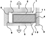
図1は、本件発明に係るピストンリングをピストンリング溝に装着した状態を説明するために軸方向で切断した概略断面図である。図1に示すように、ピストンリング1は、ピストンリング溝内6に装着された状態で、シリンダ内壁面10とピストン5との数十ミクロン程度の隙間を埋めて、燃焼ガス及びオイルをシールすると共に、ピストン5の往復運動により、シリンダ内壁面10に対して自己の持つ張力により押しつけられているピストンリングの摺動面4が油膜の厚みを適度にコントロールする。そして、ピストンリング1は、シリンダ内壁面10に油膜を介して接触しながらピストン5の往復運動(図中の矢印方向)にピストンリング1が追従することで、ピストンリング溝6内で上下運動が起こり、当該ピストンリング1の上面2,下面3と、ピストンリング溝6の上面7,下面8との間で接触が繰り返される。
FIG. 1 is a schematic cross-sectional view cut in the axial direction for explaining a state in which a piston ring according to the present invention is mounted in a piston ring groove. As shown in FIG. 1, the
この場合において、当該ピストンリング1の上面2,下面3と、ピストンリング溝の上面7,下面8との間で良好なシール状態を長期間安定して形成するには、これら面同士の密着性が重要な要素となる。ここで、当該面同士の密着性が低いと、接触する面積が小さいがゆえ、双方部材が衝突を繰り返す過程で局所的に大きなあたりが発生し、当該ピストンリング1とピストンリング溝6との接触面に摩耗損傷の発生する可能性が大きくなる。一方、当該面同士の密着性が高過ぎても、接触する面積が極めて大きいがゆえ、これらの面の保油性が低下して潤滑性に劣るため、当該ピストンリング1とピストンリング溝6との接触面に焼き付きが発生する可能性が大きくなる。
In this case, in order to stably form a good seal state between the
また、仮に当該ピストン5がアルミニウム製であって、ピストンリング溝内6にアルマイト処理等を施すことによる硬質皮膜の形成等がされていないものとするならば、接触部分となるピストンリングの上面2及び下面3において凝着が発生してしまう。図1からも、理解できるように、ピストンリングの上面2及び下面3において凝着が発生すると、ピストンリング溝上面7,下面8の摩耗が促進されてオイル消費量やブローバイガス量の増大化を招いてしまうこととなる。
Further, if the
以上のことから理解できるように、ピストンリング溝の上面及び下面に接触するピストンリングの上面及び下面の面性状が、ピストンリングによるガスシール機能及びオイルシール機能の働きを左右するものであり、ブローバイガス量及びオイル消費量の低減を図る際に重要な要素となる。 As can be understood from the above, the surface properties of the upper and lower surfaces of the piston ring contacting the upper and lower surfaces of the piston ring groove influence the functions of the gas seal function and the oil seal function by the piston ring. This is an important factor in reducing the amount of gas and oil consumption.
本件発明のピストンリングは、図1に示すピストンリングの上面及び下面における表面の負荷長さ率Rmr2が、下記数1に示す式(1)及び式(2)の各条件を満足するものである。
In the piston ring of the present invention, the load length ratio Rmr2 of the surface on the upper surface and the lower surface of the piston ring shown in FIG. 1 satisfies the conditions of the formulas (1) and (2) shown in the following
ここで、負荷長さ率Rmr2について図を用いて説明する。図2は、負荷長さ率Rmr2を説明するために、粗さ曲線から作成される負荷曲線を示した図である。なお、負荷曲線とは、粗さ曲線より各切断レベルでの負荷長さ率RmrをJIS B0601:2001に準拠して求め、当該負荷長さ率Rmr(%)を横軸とし、切断レベル(切断する高さ(単位:%又はμm))を縦軸として作成した曲線である。負荷長さ率Rmr2は、当該負荷曲線上において、指定された初期摩耗後の負荷長さ率Rmr(C0)(%)に相当する切断レベルC0から、深さz(=C0−Cn)μmだけ摩耗した後の負荷長さ率(%)をいい、この場合に「Rmr2((Rmr(C0)),z)」として表記されるものである。 Here, the load length ratio Rmr2 will be described with reference to the drawings. FIG. 2 is a diagram showing a load curve created from a roughness curve in order to explain the load length ratio Rmr2. The load curve refers to the load length ratio Rmr at each cutting level obtained from the roughness curve in accordance with JIS B0601: 2001, with the load length ratio Rmr (%) as the horizontal axis, and the cutting level (cutting) This is a curve created with the height (unit:% or μm) to be used as the vertical axis. Load length ratio Rmr2 is on the load curve, from the cutting level C 0 corresponding to the load length ratio Rmr after the specified initial wear (C 0) (%), the depth z (= C 0 -C n ) Refers to the load length ratio (%) after being worn by μm. In this case, it is expressed as “Rmr2 ((Rmr (C 0 )), z)”.
本件発明のピストンリングは、その上面及び下面の粗さを小さくするという思想の中でも、当該上面及び下面を上記式(数1)に示す条件の表面形状とすることで、より安定性を増す。ピストンリング溝の上面及び下面に接触するピストンリング上面及び下面の負荷長さ率Rmr2が、Rmr2(0.5%,0.2μm)≧30%、及びRmr2(0.5%,0.3μm)≧50%の各条件を満足しない場合には、当該ピストンリング上面及び下面とピストンリング溝の上面及び下面との接触面における密着性が低下してシール性に劣ることとなるため好ましくない。従って、上面及び下面における面性状について、負荷長さ率Rmr2を条件として規定した本件発明のピストンリングを採用することで、例えピストンリングをアルミニウム合金材からなるピストンリング溝に直接装着した場合においても、ピストンリングによる、ガスシール機能及びオイルシール機能の働きが低下するのを防ぎ、ブローバイガス量やオイル消費量の増大を効果的に抑制することが可能となる。 The piston ring of the present invention is more stable by making the upper surface and the lower surface into the surface shape under the condition shown in the above formula (Equation 1), even in the idea of reducing the roughness of the upper surface and the lower surface. The load length ratio Rmr2 of the piston ring upper and lower surfaces contacting the upper and lower surfaces of the piston ring groove is Rmr2 (0.5%, 0.2 μm) ≧ 30%, and Rmr2 (0.5%, 0.3 μm). If each condition of ≧ 50% is not satisfied, it is not preferable because the adhesiveness at the contact surface between the upper and lower surfaces of the piston ring and the upper and lower surfaces of the piston ring groove is lowered and the sealing performance is deteriorated. Therefore, even when the piston ring is directly mounted in the piston ring groove made of an aluminum alloy material by adopting the piston ring of the present invention in which the surface properties on the upper surface and the lower surface are defined on condition of the load length ratio Rmr2. It is possible to prevent the gas seal function and the oil seal function from being lowered by the piston ring, and to effectively suppress the increase in the amount of blow-by gas and the amount of oil consumption.
また、本件発明のピストンリングは、その上面及び下面の表面の十点平均粗さRzJIS(JIS B 0601:2001)は、0.2μm〜2.0μmとすることが好ましい。このように、ピストンリングの上面及び下面の表面粗さを規定することで、ピストンリング溝側面の摩擦損傷を極めて効果的に軽減化でき、ピストンリング摺動挙動の安定化を図ることができる。従って、本件発明のピストンリングは、上面及び下面について、面性状を前記式(数1)に示す条件を満たし、且つ表面の十点平均粗さRzJIS(JIS B 0601:2001)を0.2μm〜2.0μmの範囲にすることで、特にアルミニウム合金材からなるピストンリング溝に直接装着した場合に、オイル消費量やブローバイガス量の増大を抑制する効果が顕著に得られる。 In addition, the piston ring of the present invention preferably has a ten-point average roughness RzJIS (JIS B 0601: 2001) of the upper surface and the lower surface of 0.2 μm to 2.0 μm. Thus, by defining the surface roughness of the upper surface and the lower surface of the piston ring, the frictional damage on the side surface of the piston ring groove can be extremely effectively reduced, and the piston ring sliding behavior can be stabilized. Therefore, the piston ring of the present invention has a surface property of the upper surface and the lower surface that satisfies the condition shown in the above formula (Equation 1), and the surface ten-point average roughness RzJIS (JIS B 0601: 2001) is 0.2 μm to By setting the thickness within the range of 2.0 μm, the effect of suppressing an increase in oil consumption and blow-by gas amount can be obtained particularly when the piston ring groove is made of aluminum alloy material.
ここで、ピストンリングの上面及び下面の表面の十点平均粗さRzJIS(JIS B 0601:2001)が、0.2μm未満の場合には、設備導入に伴うコストの増加や、製品歩留まりの低下等の問題があるため好ましくない。また、ピストンリングの上面及び下面の表面粗さが小さくなり過ぎることでピストンリング溝上下面との密着性の向上が図れる反面、当該ピストンリング表面における保油性が低下し潤滑性に劣ることとなるため、焼き付きが起こりやすくなる。一方、ピストンリングの上面及び下面の表面の十点平均粗さRzJIS(JIS B 0601:2001)が、2.0μmを超える場合には、表面の粗さが大きいが故に初期馴染み性も低下すると同時に、ピストンリングによるピストンリング溝に対する攻撃性が増大して、接触するピストンリング溝上下面に対して摩擦損傷を与える可能性が高くなるため好ましくない。 Here, when the ten-point average roughness RzJIS (JIS B 0601: 2001) of the upper and lower surfaces of the piston ring is less than 0.2 μm, the cost increases due to the introduction of equipment, the product yield decreases, etc. It is not preferable because of the problem Also, since the surface roughness of the upper and lower surfaces of the piston ring becomes too small, the adhesion with the upper and lower surfaces of the piston ring groove can be improved, but the oil retaining property on the surface of the piston ring is lowered and the lubricity is inferior. , Seizure is likely to occur. On the other hand, when the ten-point average roughness RzJIS (JIS B 0601: 2001) of the upper and lower surfaces of the piston ring exceeds 2.0 μm, the initial adaptability is reduced because the surface roughness is large. This is not preferable because the aggressiveness of the piston ring against the piston ring groove is increased, and the possibility of causing frictional damage to the upper and lower surfaces of the piston ring groove in contact with the piston ring groove is increased.
また、本件発明のピストンリングは、その上面及び下面に硬質層が形成されており、当該硬質層におけるビッカース硬度(HV)が700HV0.1〜3000HV0.1であることが好ましい。本件発明のピストンリングの上面及び下面に硬質層を形成することで、耐久性の向上を図ることができる。なお、ピストンリングの上面及び下面に当該硬質層を形成した後に、ピストンリングの上面及び下面について平滑化処理を施すことで、本件発明で規定する条件のピストンリングの表面性状を安定して得ることができる。 Moreover, it is preferable that the hard layer is formed in the upper surface and lower surface of the piston ring of this invention, and the Vickers hardness (HV) in the said hard layer is 700HV0.1-3000HV0.1. Durability can be improved by forming hard layers on the upper and lower surfaces of the piston ring of the present invention. In addition, after forming the said hard layer in the upper surface and lower surface of a piston ring, the surface property of the piston ring of the conditions prescribed | regulated by this invention can be obtained stably by performing a smoothing process about the upper surface and lower surface of a piston ring. Can do.
ここで、ピストンリングの上面及び下面に形成されている硬質層におけるビッカース硬度(HV)が700HV0.1未満の場合には、ピストンリングの耐久性の向上が十分に図れない。また、ピストンリングの上面及び下面に形成されている硬質層におけるビッカース硬度(HV)が3000HV0.1を超えると、ピストンリングの上面及び下面が硬くなり過ぎることになり、脆化して脆くなるため、耐衝撃特性に劣るようになるため好ましくない。 Here, when the Vickers hardness (HV) in the hard layer formed on the upper surface and the lower surface of the piston ring is less than 700 HV0.1, the durability of the piston ring cannot be sufficiently improved. Also, if the Vickers hardness (HV) in the hard layer formed on the upper surface and the lower surface of the piston ring exceeds 3000 HV0.1, the upper surface and the lower surface of the piston ring will become too hard and become brittle and brittle. Since it becomes inferior to an impact-resistant characteristic, it is not preferable.
また、本件発明のピストンリングは、スチール製又は鋳鉄製であり、当該ピストンリングの上面及び下面に形成される硬質層が窒化処理層又はクロムメッキ層又はダイアモンド ライク カーボン層である。このように、ピストンリングの上面及び下面に窒化処理層又はクロムメッキ層又はダイアモンド ライク カーボン層(以下、「DLC層」と称する。)を形成することによって、スチール製のピストンリングを、アルミニウム合金製のピストンと組み合わせて使用しても、内燃機関として求められる長寿命化が図れる。なお、図1に示すように、当該硬質層11は、ピストンリングのピストンリング溝と接触する上面及び下面のみならず、シリンダ内壁面との摺動面を含む全表面に形成しても良い。 The piston ring of the present invention is made of steel or cast iron, and the hard layers formed on the upper and lower surfaces of the piston ring are a nitriding layer, a chrome plating layer, or a diamond-like carbon layer. Thus, by forming a nitriding layer, a chrome plating layer, or a diamond-like carbon layer (hereinafter referred to as “DLC layer”) on the upper and lower surfaces of the piston ring, the steel piston ring is made of an aluminum alloy. Even if it is used in combination with this piston, it is possible to extend the life required for an internal combustion engine. In addition, as shown in FIG. 1, you may form the said hard layer 11 not only on the upper surface and lower surface which contact the piston ring groove | channel of a piston ring but on the whole surface including a sliding surface with a cylinder inner wall surface.
そして、以上に述べてきた窒化処理層又はクロムメッキ層の表面には、クロムメッキ、複合クロムメッキ、複合メッキ、溶射、物理蒸着(PVD)、化学蒸着(CVD)等の手法を用いて、更に表面処理を施すこともできる。なお、DLC層は、摩擦係数が低い低摩擦材料として知られており、当該DLC層をピストンリングの表面に形成した窒化処理層又はクロムメッキ層の最外層に設けることで、当該ピストンリングの耐摩耗特性を飛躍的に向上させることが可能となる。 And, on the surface of the nitriding layer or chromium plating layer described above, using a technique such as chromium plating, composite chromium plating, composite plating, thermal spraying, physical vapor deposition (PVD), chemical vapor deposition (CVD), A surface treatment can also be applied. The DLC layer is known as a low friction material having a low friction coefficient. By providing the DLC layer on the outermost layer of the nitriding layer or the chrome plating layer formed on the surface of the piston ring, the DLC layer is resistant to the piston ring. The wear characteristics can be dramatically improved.
上述したように、ピストンリングは、一般的にトップリング、セカンドリング、及びオイルリングを1セットとしてピストンに装着して用いられるものである。本件発明のピストンリングは、トップリングとセカンドリングとのどちらに対しても好適に用いることができる。また、図1に示すピストンリング1は、軸方向断面で見て略矩形形状であるが、本件発明のピストンリングの形状はこれに限定されるものではない。例えば、ピストンリングの摺動面4がテーパー形状を備えたものであっても構わない。
As described above, a piston ring is generally used by attaching a top ring, a second ring, and an oil ring to a piston as a set. The piston ring of the present invention can be suitably used for both the top ring and the second ring. Moreover, although the
参考までに、トップリング及びセカンドリングは、燃焼ガスとピストンからの熱を受けるため、耐熱性に優れた材質で、且つエンジン出力の低下や潤滑油消費量の増加が起きないように耐摩耗性、耐スカッフ性等を考慮した材質によって構成される。例えば、最も燃焼室側に位置するトップリングには、シリンダライナとの摺動面を窒化処理したマルテンサイト系ステンレス鋼製リング、シリンダライナとの摺動面にクロムメッキを施したSWOSC−V鋼製のリング等が広く用いられる。また、セカンドリングには、高級鋳鉄製リング又は合金鋳鉄製リングが採用され、特に高級鋳鉄製リングの摺動面にクロムメッキを施したものが多用される。 For reference, the top ring and the second ring receive heat from the combustion gas and the piston, so they are made of a material with excellent heat resistance and wear resistance so that the engine output does not decrease and the lubricating oil consumption does not increase. It is made of a material considering scuff resistance and the like. For example, the top ring located closest to the combustion chamber includes a martensitic stainless steel ring that has been nitrided on the sliding surface with the cylinder liner, and SWOSC-V steel that has been chrome plated on the sliding surface with the cylinder liner. A ring made of metal is widely used. Further, as the second ring, a high-grade cast iron ring or an alloy cast iron ring is employed, and in particular, a high-grade cast iron ring with a chrome plating applied to the sliding surface is frequently used.
以下、実施例および比較例を示して本件発明を具体的に説明する。なお、本件発明は、以下の実施例に限定されるものではない。 Hereinafter, the present invention will be specifically described with reference to Examples and Comparative Examples. Note that the present invention is not limited to the following examples.
ブローバイガス量確認試験: 本確認試験を実施するにあたり、ブローバイ量の測定は、各回転数でエンジンを回転させ、ブローバイガス量(l/min )を測定した。これらの結果から、全負荷(WOT)で回転数11800rpmにおけるクランクケース内の上限圧力を0.0285kgf/cm2としてブローバイガス量を算出した。なお、ピストンリングの組み合わせは、トップリング、セカンドリング、オイルリングとした。このときのトップリングは、13Cr鋼からなる軸方向高さが1.2mm、径方向厚さが2.9mmのものにガス窒化処理を施したものを用いた。セカンドリングは、FC材からなり、軸方向高さが1.2mm、径方向厚さが3.4mmのものを用いた。そして、本確認試験を実施するにあたり、合い口部の隙間幅は、トップリングが0.15mm、セカンドリングが0.20mm、そしてオイルリングが0.50mmのものを用いた。 Blow-by gas amount confirmation test: In carrying out this confirmation test, the blow-by amount was measured by rotating the engine at each rotation speed and measuring the blow-by gas amount (l / min). From these results, the blow-by gas amount was calculated by setting the upper limit pressure in the crankcase at a rotational speed of 11800 rpm at a full load (WOT) to 0.0285 kgf / cm 2 . The piston ring combination was a top ring, a second ring, and an oil ring. At this time, the top ring made of 13Cr steel having an axial height of 1.2 mm and a radial thickness of 2.9 mm was subjected to gas nitriding treatment. The second ring was made of FC material, and had an axial height of 1.2 mm and a radial thickness of 3.4 mm. Then, in carrying out this confirmation test, the gap width of the abutment portion was 0.15 mm for the top ring, 0.20 mm for the second ring, and 0.50 mm for the oil ring.
参考として、トップリングを構成する13Cr鋼及びセカンドリングを構成するFC材に関して述べておく。ここで言う13Cr鋼は、炭素0.65質量%、ケイ素0.31質量%、マンガン0.30質量%、クロム13.4質量%、モリブデン0.27質量%、リン0.02質量%、硫黄0.01質量%、残部鉄及び不可避不純物の組成を備えたものである。また、当該トップリングは、その表面にガス窒化処理を施した結果、形成された窒化処理層最表面のビッカース硬度(HV)が1100HV0.1であり、ビッカース硬度(HV)が700HV0.1以上の窒化拡散層がトップリング全周に20μm〜40μmの深さで形成されたものを用いた。そして、ここで言うFC材とは、炭素3.41質量%、ケイ素2.05質量%、マンガン0.65質量%、リン0.30質量%、硫黄0.08質量%、クロム0.10質量%、銅0.10質量%、残部鉄及び不可避不純物の組成を備えるFC250材相当のものである。 For reference, the 13Cr steel constituting the top ring and the FC material constituting the second ring will be described. The 13Cr steel mentioned here is carbon 0.65 mass%, silicon 0.31 mass%, manganese 0.30 mass%, chromium 13.4 mass%, molybdenum 0.27 mass%, phosphorus 0.02 mass%, sulfur. It has a composition of 0.01% by mass, balance iron and inevitable impurities. Further, as a result of performing gas nitriding treatment on the top ring, the top surface of the formed nitriding layer has a Vickers hardness (HV) of 1100 HV0.1 and a Vickers hardness (HV) of 700 HV0.1 or more. A nitrided diffusion layer formed on the entire circumference of the top ring with a depth of 20 μm to 40 μm was used. And FC material said here is carbon 3.41 mass%, silicon 2.05 mass%, manganese 0.65 mass%, phosphorus 0.30 mass%, sulfur 0.08 mass%, chromium 0.10 mass. %, Copper 0.10% by mass, the balance iron and unavoidable impurities, FC250 material equivalent.
ちなみに、オイルリング本体は、炭素0.65質量%、ケイ素0.38質量%、マンガン0.35質量%、クロム13.50質量%、モリブデン0.3質量%、リン0.01質量%、硫黄0.01質量%、残部鉄及び不可避不純物の組成の所謂13Cr鋼(SUS410相当)を用い、且つ、ガス窒化処理を施しているものを用いた。 By the way, the oil ring body is composed of carbon 0.65% by mass, silicon 0.38% by mass, manganese 0.35% by mass, chromium 13.50% by mass, molybdenum 0.3% by mass, phosphorus 0.01% by mass, sulfur. A so-called 13Cr steel (SUS410 equivalent) having a composition of 0.01% by mass, the balance iron and inevitable impurities, and subjected to gas nitriding treatment was used.
そして、ピストンは、ピストンリング溝の上下面の粗さが、十点平均粗さRzJIS(JIS B 0601:2001)で2μm以下のものを使用した。 And the piston used that the roughness of the upper and lower surfaces of the piston ring groove is 2 μm or less with a ten-point average roughness RzJIS (JIS B 0601: 2001).
上述した条件でブローバイガス量確認試験を行った結果を表1に示す。表1は、各エンジン回転数毎のブローバイガス量をピストンリングの上面及び下面における表面の負荷長さ率Rmr2を本件発明の条件範囲内の実施例試料と本件発明の条件範囲外の比較例試料(従来品に相当)とで確認を行った結果を示している。そして、この結果として、図3には、本件発明の実施例及び比較例における、ブローバイ比とエンジン回転数(rpm)との関係をグラフにて示す。ここで、ブローバイ比は、実施例試料の最大エンジン回転数におけるブローバイ量を「2」として、これに対する相対比で表示している。 Table 1 shows the results of the blow-by gas amount confirmation test under the above-described conditions. Table 1 shows the amount of blow-by gas at each engine speed, the load length ratio Rmr2 of the surface on the upper and lower surfaces of the piston ring, the example sample within the condition range of the present invention and the comparative example sample outside the condition range of the present invention. (Equivalent to the conventional product) shows the result of confirmation. As a result of this, FIG. 3 is a graph showing the relationship between the blow-by ratio and the engine speed (rpm) in the examples and comparative examples of the present invention. Here, the blow-by ratio is expressed as a relative ratio with respect to the blow-by amount at the maximum engine speed of the example sample as “2”.
表2及び図3より、比較例試料を用いた場合は、エンジン回転数が高くなるに従いブローバイガス量の増大が顕著になっていくことが分かる。一般的に、エンジン回転数を高くするに従って、ピストン及びピストンリングが高温となり、この結果、オイルの粘度が低下して潤滑性に劣ることで焼き付きが生じたり、ピストンリングに凝着が発生しやすくなる。それにもかかわらず、実施例試料を用いた場合には、エンジン回転数が高くなっても、ブローバイガス量にさほど変化が見受けられない。このことからも、ピストンリングの上面及び下面における負荷長さ率Rmr2を本件発明の条件範囲内としたピストンリングを用いた場合には、当該条件範囲外のピストンリングと比較して長時間安定してオイル消費量やブローバイガス量の増大を抑制する効果を発揮することが実証された。 From Table 2 and FIG. 3, it can be seen that when the comparative sample is used, the increase in the amount of blow-by gas becomes more significant as the engine speed increases. In general, as the engine speed is increased, the piston and the piston ring become hot. As a result, the oil viscosity decreases and the lubricity is poor, and seizure occurs, and the piston ring is likely to adhere. Become. Nevertheless, when the example sample is used, even if the engine speed increases, the amount of blow-by gas does not change so much. Also from this, when using a piston ring in which the load length ratio Rmr2 on the upper surface and the lower surface of the piston ring is within the condition range of the present invention, it is stable for a long time compared to a piston ring outside the condition range. It has been demonstrated that it has the effect of suppressing the increase in oil consumption and blow-by gas.
以上説明してきたように、本件発明のピストンリングは、その上面及び下面の表面性状を本件発明に規定する条件を満たすことによって、ピストンリングの上面及び下面と、ピストンリング溝の上面及び下面との間で良好なシール状態を形成することができる。また、本件発明のピストンリングは、アルミニウム合金製のピストンとの組合せとして用いることで、オイル消費量やブローバイガス量の増大を抑制する効果をより発揮することができる。 As described above, the piston ring according to the present invention satisfies the conditions specified in the present invention for the surface properties of the upper surface and the lower surface, so that the upper surface and the lower surface of the piston ring and the upper surface and the lower surface of the piston ring groove are formed. A good sealing state can be formed between them. Moreover, the piston ring of this invention can exhibit more the effect which suppresses the increase in oil consumption and blow-by gas amount by using it as a combination with the piston made from aluminum alloy.
本件発明のピストンリングは、ピストンリングの上面及び下面における表面の負荷長さ率Rmr2が、(0.5%,0.2μm)≧30%、及び(0.5%,0.3μm)≧50%の各条件を満足するものとしたことで、例えアルミニウム合金材からなるピストンリング溝に直接装着した場合であっても、オイル消費量やブローバイガス量の増大を十分に抑制することができる。また、本件発明のピストンリングを採用すれば、あらゆるエンジン回転域でオイル消費量やブローバイガス量を減少させることができるため、ハイパワー仕様エンジンなど幅広いニーズに応えることができる。 In the piston ring of the present invention, the surface load length ratio Rmr2 on the upper and lower surfaces of the piston ring is (0.5%, 0.2 μm) ≧ 30% and (0.5%, 0.3 μm) ≧ 50. %, The increase in oil consumption and blow-by gas amount can be sufficiently suppressed even when directly mounted in a piston ring groove made of an aluminum alloy material. Further, if the piston ring of the present invention is adopted, the oil consumption and blow-by gas amount can be reduced in all engine rotation ranges, so that it can meet a wide range of needs such as a high power engine.
1 ピストンリング
2 ピストンリング上面
3 ピストンリング下面
4 ピストンリング摺動面
5 ピストン
6 ピストンリング溝
7 ピストンリング溝上面
8 ピストンリング溝下面
9 シリンダ
10 シリンダ内壁面
11 硬質層
DESCRIPTION OF
Claims (5)
当該ピストンリングの上面及び下面における表面の負荷長さ率Rmr2は、下記数1に示す式(1)及び式(2)の各条件を満足するものであることを特徴とするピストンリング。
The piston ring characterized in that the load length ratio Rmr2 of the surface on the upper surface and the lower surface of the piston ring satisfies the conditions of the following formula (1) and formula (2).
Priority Applications (1)
| Application Number | Priority Date | Filing Date | Title |
|---|---|---|---|
| JP2010043482A JP5376668B2 (en) | 2010-02-26 | 2010-02-26 | piston ring |
Applications Claiming Priority (1)
| Application Number | Priority Date | Filing Date | Title |
|---|---|---|---|
| JP2010043482A JP5376668B2 (en) | 2010-02-26 | 2010-02-26 | piston ring |
Publications (2)
| Publication Number | Publication Date |
|---|---|
| JP2011179573A JP2011179573A (en) | 2011-09-15 |
| JP5376668B2 true JP5376668B2 (en) | 2013-12-25 |
Family
ID=44691290
Family Applications (1)
| Application Number | Title | Priority Date | Filing Date |
|---|---|---|---|
| JP2010043482A Active JP5376668B2 (en) | 2010-02-26 | 2010-02-26 | piston ring |
Country Status (1)
| Country | Link |
|---|---|
| JP (1) | JP5376668B2 (en) |
Families Citing this family (5)
| Publication number | Priority date | Publication date | Assignee | Title |
|---|---|---|---|---|
| CN102741535B (en) * | 2010-01-29 | 2014-09-10 | 日本活塞环株式会社 | Piston ring |
| JP6314015B2 (en) * | 2014-03-31 | 2018-04-18 | 日本ピストンリング株式会社 | Combination of piston and piston ring |
| BR102015025731B1 (en) * | 2015-10-08 | 2021-05-18 | Mahle Metal Leve S/A | sliding element |
| JP7347423B2 (en) * | 2018-07-27 | 2023-09-20 | 株式会社プロテリアル | Deformed wire rod for pressure ring |
| WO2024053065A1 (en) * | 2022-09-08 | 2024-03-14 | Tpr株式会社 | Compression ring |
Family Cites Families (4)
| Publication number | Priority date | Publication date | Assignee | Title |
|---|---|---|---|---|
| JPH1193464A (en) * | 1997-09-24 | 1999-04-06 | Matsushita Electric Works Ltd | Execution construction of wall |
| JP4678802B2 (en) * | 2000-11-06 | 2011-04-27 | 本田技研工業株式会社 | Sliding contact surface member |
| JP2006275269A (en) * | 2005-03-30 | 2006-10-12 | Nippon Piston Ring Co Ltd | Combined sliding member |
| JP5828575B2 (en) * | 2008-03-04 | 2015-12-09 | 日産自動車株式会社 | piston ring |
-
2010
- 2010-02-26 JP JP2010043482A patent/JP5376668B2/en active Active
Also Published As
| Publication number | Publication date |
|---|---|
| JP2011179573A (en) | 2011-09-15 |
Similar Documents
| Publication | Publication Date | Title |
|---|---|---|
| JP5794634B2 (en) | piston ring | |
| US8123227B2 (en) | Sliding member | |
| EP1886009B1 (en) | Coated power cylinder components for diesel engines | |
| EP2677152B1 (en) | Variable thickness coatings for cylinder liners | |
| JP5545774B2 (en) | Piston ring and piston device | |
| US8240676B2 (en) | Piston ring | |
| JP5583207B2 (en) | Sliding member | |
| US9353864B2 (en) | Oil ring for internal combustion engine | |
| KR20130048719A (en) | Sliding element, in particular a piston ring, and method for cating a sliding element | |
| JP5376668B2 (en) | piston ring | |
| KR20110073557A (en) | Sliding element in an internal combustion engine, in particular a piston ring | |
| EP3048287A1 (en) | Combination of cylinder bore and piston ring | |
| CN107035564B (en) | Sliding element | |
| US9261191B2 (en) | Piston ring for internal combustion engine | |
| JP2023133290A (en) | piston ring | |
| US20180010689A1 (en) | Polymer coating in cracked piston ring coating | |
| JP5981013B1 (en) | Piston ring for internal combustion engine | |
| JP5719031B2 (en) | piston ring | |
| JP2005264978A (en) | Pressure ring | |
| CN110431334B (en) | Power transmission device for heat engine | |
| JP5826958B1 (en) | Piston ring for internal combustion engine | |
| JP6387228B2 (en) | Piston ring for internal combustion engine | |
| JP6889692B2 (en) | Alcohol fuel piston | |
| WO2015056450A1 (en) | Piston ring for internal combustion engine | |
| JP2015078752A (en) | Piston ring for internal combustion engine |
Legal Events
| Date | Code | Title | Description |
|---|---|---|---|
| A621 | Written request for application examination |
Free format text: JAPANESE INTERMEDIATE CODE: A621 Effective date: 20121225 |
|
| TRDD | Decision of grant or rejection written | ||
| A01 | Written decision to grant a patent or to grant a registration (utility model) |
Free format text: JAPANESE INTERMEDIATE CODE: A01 Effective date: 20130919 |
|
| A977 | Report on retrieval |
Free format text: JAPANESE INTERMEDIATE CODE: A971007 Effective date: 20130919 |
|
| A61 | First payment of annual fees (during grant procedure) |
Free format text: JAPANESE INTERMEDIATE CODE: A61 Effective date: 20130920 |
|
| R150 | Certificate of patent or registration of utility model |
Ref document number: 5376668 Country of ref document: JP Free format text: JAPANESE INTERMEDIATE CODE: R150 Free format text: JAPANESE INTERMEDIATE CODE: R150 |