JP4673385B2 - Brake lamp lighting operation structure in tractor - Google Patents
Brake lamp lighting operation structure in tractor Download PDFInfo
- Publication number
- JP4673385B2 JP4673385B2 JP2008034679A JP2008034679A JP4673385B2 JP 4673385 B2 JP4673385 B2 JP 4673385B2 JP 2008034679 A JP2008034679 A JP 2008034679A JP 2008034679 A JP2008034679 A JP 2008034679A JP 4673385 B2 JP4673385 B2 JP 4673385B2
- Authority
- JP
- Japan
- Prior art keywords
- brake
- pedal
- brake pedal
- main
- rod
- Prior art date
- Legal status (The legal status is an assumption and is not a legal conclusion. Google has not performed a legal analysis and makes no representation as to the accuracy of the status listed.)
- Active
Links
Images


Landscapes
- Transmission Of Braking Force In Braking Systems (AREA)
- Braking Elements And Transmission Devices (AREA)
- Lighting Device Outwards From Vehicle And Optical Signal (AREA)
Description
本発明は、同じブレーキ装置に対して独立して操作できる主ブレーキペダルと駐車ブレーキペダルとを設けたトラクタにおけるブレーキランプの点灯操作構造に関する。 The present invention relates to a lighting operation structure of a brake lamp in a tractor provided with a main brake pedal and a parking brake pedal that can be independently operated with respect to the same brake device.
従来のトラクタのブレーキ操作機構として、例えば、特許文献1に開示されているように、トラクタ走行機体の運転部に、同じブレーキ装置に対して第1連係機構を介して連係させた左右一対のサイドブレーキペダルからなる主ブレーキペダル及び第2連係機構を介して連係させた駐車ブレーキペダルを設け、主ブレーキペダル及び駐車ブレーキペダルはそれぞれ独立して踏み込み操作することによりブレーキ装置を制動状態に操作するように構成したものが知られている。
特許文献1には明示されていないが、この構造のものには主ブレーキペダルの操作系に主ブレーキペダルの踏み込み操作に連係して入り作動して車体後部に設けたブレーキランプを点灯させるブレーキスイッチが備えられている。しかし、この構造のものでは、キースイッチをオンした状態で駐車ブレーキペダルを踏み操作したときには、主ブレーキペダルを含む主ブレーキペダルの操作系が一緒に作動してブレーキランプが点灯する不都合がある。
As a conventional tractor brake operating mechanism, for example, as disclosed in Patent Document 1, a pair of left and right sides linked to the same brake device via the first linkage mechanism in the operating part of the tractor traveling machine body A main brake pedal composed of a brake pedal and a parking brake pedal linked through a second linkage mechanism are provided, and the main brake pedal and the parking brake pedal are each operated to be depressed independently to operate the brake device in a braking state. It is known what has been configured.
Although not explicitly disclosed in Patent Document 1, a brake switch having this structure enters the operation system of the main brake pedal in conjunction with the depression operation of the main brake pedal and operates to actuate a brake lamp provided at the rear of the vehicle body Is provided. However, in this structure, when the parking brake pedal is depressed with the key switch turned on, the operation system of the main brake pedal including the main brake pedal is operated together, and the brake lamp is lit.
本発明は、キースイッチがオンした状態で長時間駐車ブレーキペダルを踏み込み操作した状態で放置したときなどにブレーキランプが点き放しになるのを防止することを目的とする。 An object of the present invention is to prevent the brake lamp from being turned off when the key switch is turned on and the parking brake pedal is depressed for a long time and left unattended.
〔構成〕
本発明の第1の特徴は、トラクタ走行機体の運転部に、同じブレーキ装置に対して第1連係機構を介して連係させた主ブレーキペダル及び第2連係機構を介して連係させた駐車ブレーキペダルを設け、前記主ブレーキペダル及び駐車ブレーキペダルはそれぞれ独立して踏み込み操作することにより前記ブレーキ装置を各別に制動状態に操作するように構成するとともに、前記第1連係機構に対してのみ当該第1連係機構の作動によりブレーキランプを点消灯させるブレーキスイッチを連係させ、前記駐車ブレーキペダルの踏み込み及び戻し操作では前記ブレーキランプを点消灯させないで、前記主ブレーキペダルの踏み込み操作により前記ブレーキスイッチが入り作動して前記ブレーキランプを点灯させ、前記主ブレーキペダルの戻し操作で前記ブレーキスイッチが切り作動して前記ブレーキランプを消灯させるように構成し、
前記ブレーキ装置を操作する操作アームにブラケットを設けて、このブラケットに前後に貫通する2つの貫通穴を形成し、前記2つの貫通穴のうちの一方の貫通穴に前記第1連係機構を構成する第1ロッドの後端側を挿通して、前記ブラケットの後側に位置する前記第1ロッドの後端部に第1接当部を連結し、前記2つの貫通穴のうちの他方の貫通穴に前記第2連係機構を構成する第2ロッドの後端側を挿通して、前記ブラケットの後側に位置する前記第2ロッドの後端部に第2接当部を連結し、
前記主ブレーキペダルを踏み込み操作して前記第1ロッドを引き操作したときには、前記他方の貫通穴による融通によって前記駐車ブレーキペダルを作動させないで、前記第1接当部を介して前記操作アームを揺動させて前記ブレーキ装置を制動作動させるとともに、前記ブレーキスイッチが作動してブレーキランプを点灯させ、且つ、前記駐車ブレーキペダルを踏み込み操作して前記第2ロッドを引き操作したときには、前記一方の貫通穴による融通によって前記主ブレーキペダルを作動させないで、前記第2接当部を介して前記操作アームを揺動させて前記ブレーキ装置を制動作動させるように構成した点にある。
〔Constitution〕
A first feature of the present invention is that a parking brake pedal is linked to a driving part of a tractor traveling machine body via a first linkage mechanism and a main brake pedal linked to the same brake device via a second linkage mechanism. And the main brake pedal and the parking brake pedal are configured to operate the brake device in a braking state separately by depressing each of the main brake pedal and the parking brake pedal, and to the first linkage mechanism only. A brake switch that turns off the brake lamp by operating the linkage mechanism is linked, and the brake switch is turned on and operated by depressing the main brake pedal without turning off the brake lamp by depressing and returning the parking brake pedal. in and to light the brake lamp, back of the main brake pedal operation Serial brake switch is cut actuated configured to turn off the brake lamp,
A bracket is provided on an operating arm for operating the brake device, two through holes are formed through the bracket in the front-rear direction, and the first linkage mechanism is configured in one of the two through holes. A rear end side of the first rod is inserted, a first contact portion is connected to a rear end portion of the first rod located on the rear side of the bracket, and the other through hole of the two through holes The second rod constituting the second linkage mechanism is inserted through the rear end side of the second rod, the second contact portion is coupled to the rear end portion of the second rod located on the rear side of the bracket,
When the first brake is operated by depressing the main brake pedal, the parking brake pedal is not actuated by the accommodation through the other through hole, and the operation arm is swung through the first contact portion. When the brake device is actuated to actuate the brake, the brake switch is actuated to light the brake lamp, and the parking brake pedal is depressed to pull the second rod. The main brake pedal is not actuated by the accommodation through the hole, but the operation arm is swung via the second contact portion to brake the brake device .
〔作用〕
本発明の第1特徴によると、主ブレーキペダルを踏んだときには、ブレーキランプが点灯するから、後続の車両の運転者に停止することを知らせることができながら、駐車ブレーキペダルを操作して同じブレーキ装置を駐車ブレーキとして使用するときにはブレーキランプが点灯しない。
[Action]
According to the first feature of the present invention, when the main brake pedal is depressed, the brake lamp is lit, so that the driver of the following vehicle can be informed that the vehicle is stopped, and the parking brake pedal is operated to operate the same brake. When the device is used as a parking brake, the brake lamp does not light up.
〔発明の効果〕
従って、本発明の第1特徴によると、キースイッチをオンした状態で長時間駐車ブレーキペダルを踏み込み操作した姿勢の状態で放置した場合であっても、ブレーキランプが点き放しになるのを防止することができる。
〔The invention's effect〕
Therefore, according to the first feature of the present invention, it is possible to prevent the brake lamp from being left unlit even when the key switch is turned on and the parking brake pedal is left depressed for a long time. can do.
〔作用〕[Action]
本発明の第1特徴によると、主ブレーキペダルを踏み込み操作しているときは駐車ブレーキペダルを作動させず、駐車ブレーキペダルを踏み込み操作しているときには主ブレーキペダルを作動させないでブレーキ装置を制動作動させることができるから、特に駐車ブレーキペダルを単独操作するときは、従来構造のものに比べて、駐車ブレーキペダルの操作が軽く行え、又駐車ブレーキペダルの戻し操作時に主ブレーキペダルの急激な復帰による衝撃音を発生させることもない。According to the first feature of the present invention, when the main brake pedal is depressed, the parking brake pedal is not operated, and when the parking brake pedal is depressed, the brake device is braked without operating the main brake pedal. Therefore, when operating the parking brake pedal alone, the parking brake pedal can be operated more lightly compared to the conventional structure, and when the parking brake pedal is returned, the main brake pedal is suddenly returned. No impact sound is generated.
又、主ブレーキペダルを踏んだ状態で駐車ブレーキペダルを踏み操作することもでき、この場合は駐車ブレーキペダルの操作が軽く行うことができる。In addition, the parking brake pedal can be depressed while the main brake pedal is depressed. In this case, the parking brake pedal can be operated lightly.
そして、本来の主ブレーキペダルの操作によって制動するブレーキ装置を、駐車ブレーキペダルを操作して駐車ブレーキとして使用するときには、ブレーキランプは点灯しない。When the brake device that brakes by operating the original main brake pedal is used as a parking brake by operating the parking brake pedal, the brake lamp does not light up.
〔発明の効果〕〔The invention's effect〕
本発明の第1特徴によると、駐車ブレーキペダルの操作が容易簡単な上に軽く行える。特に主ブレーキペダルを操作して停車した直後に主ブレーキペダルを踏みながら駐車ブレーキペダルを操作することで、簡単確実にしかも軽い操作で楽に駐車ブレーキ操作を行うことができる。本来の主ブレーキペダルの操作によって制動するブレーキ装置を、駐車ブレーキとして使用したときには、長時間駐車ブレーキペダルを踏み込み操作した姿勢の状態であってもブレーキランプが点き放しになることがない。 According to the first feature of the present invention, the parking brake pedal can be operated easily and lightly. In particular, by operating the parking brake pedal while depressing the main brake pedal immediately after operating the main brake pedal, the parking brake operation can be performed easily and securely with a light operation. When a brake device that brakes by operating the original main brake pedal is used as a parking brake, the brake lamp will not be left unlit even when the parking brake pedal is depressed for a long time.
〔構成〕〔Constitution〕
本発明の第2特徴は、第1特徴の発明において、前記ブレーキスイッチをミッションケースの側部に固定し、前記ブレーキスイッチを押圧操作するスイッチ操作用ブラケットを前記第1ロッドの前後中間部に固定し、前記第1ロッドの押し引き操作により前記スイッチ操作用ブラケットを介して前記ブレーキスイッチが操作されるように構成した点にある。According to a second aspect of the present invention, in the first aspect of the invention, the brake switch is fixed to a side portion of the transmission case, and a switch operation bracket for pressing the brake switch is fixed to the front and rear intermediate portion of the first rod. In addition, the brake switch is configured to be operated via the switch operation bracket by pushing and pulling the first rod.
〔構成〕
本発明の第3特徴は、第1または第2特徴の発明において、前記主ブレーキペダルをステップフロアにおける運転座席を中心とした前部の右側に配置し、主クラッチ用の主クラッチペダルをステップフロアにおける運転座席を中心とした前部の左側に配置し、前記駐車ブレーキペダルを前記主クラッチペダルの後方に配置した点にある。
〔Constitution〕
According to a third aspect of the present invention, in the first or second aspect of the invention, the main brake pedal is disposed on the right side of the front part centering on the driver seat on the step floor, and the main clutch pedal for the main clutch is disposed on the step floor. The parking brake pedal is arranged at the rear of the main clutch pedal.
〔作用〕
トラクタにおいては左からの乗り降りが普通になっている。中型機では、右側に多くの操作レバーが配置されており、右からの乗り降りが左側の乗り降りに比べて行い難い。特にミッドマウント型のモアを備えたトラクタでは、右にディスチャージ口があり、右からの乗り降りが行い難い。
本発明の第3特徴によると、駐車ブレーキペダルを座席近傍の左側下方に設けてあるから、乗り降りのときに駐車ブレーキペダルの突出具合を目視でき、駐車ブレーキ操作のし忘れがあれば気づきやすく、操作忘れがあれば降車時に行える。
又、降車した状態のままでも手動操作で簡単に制動並びに制動解除の駐車ブレーキ操作を行うことができる。
[Action]
In tractors, getting on and off from the left is normal. In medium-sized aircraft, many control levers are arranged on the right side, and getting on and off from the right is harder than on the left side. In particular, a tractor with a mid-mount mower has a discharge port on the right, making it difficult to get on and off from the right.
According to the third feature of the present invention, since the parking brake pedal is provided on the lower left side in the vicinity of the seat, the protruding state of the parking brake pedal can be visually observed when getting on and off, and it is easy to notice if you forget to operate the parking brake. If you forget to operate, you can do it when you get off.
In addition, the parking brake operation for braking and releasing can be easily performed by manual operation even in the state of getting off.
〔発明の効果〕
本発明の第3特徴によると、降車時に駐車ブレーキ操作忘れを少なくすることができ、降車した状態で駐車ブレーキ操作をするときに、駐車ブレーキペダルの踏み面の位置を考える煩わしさもなく、簡単容易に制動並びに制動解除の駐車ブレーキ操作を行える利点がある。
〔The invention's effect〕
According to the third feature of the present invention, it is possible to reduce forgetting to operate the parking brake when getting off the vehicle, and when performing the parking brake operation when getting off the vehicle, there is no need to worry about the position of the tread surface of the parking brake pedal. There is an advantage that parking brake operation for braking and braking can be performed.
〔構成〕
本発明の第4特徴は、第1〜第3特徴のいずれかの発明において、前記主ブレーキペダルは左右一対のサイドブレーキペダルからなり、前記ブレーキ装置は前記左右一対の各サイドブレーキペダルに対して各別に連係された左サイドブレーキ装置と右サイドブレーキ装置からなり、前記ブレーキスイッチは左右のサイドブレーキペダルの操作系における少なくとも左右いずれか一方に設け、当該サイドブレーキペダルの踏み込み及び戻し操作に連係して前記ブレーキランプを点消灯させるように構成した点にある。
〔Constitution〕
According to a fourth feature of the present invention, in the invention according to any one of the first to third features, the main brake pedal includes a pair of left and right side brake pedals, and the brake device is connected to the pair of left and right side brake pedals. It consists of a left side brake device and a right side brake device that are linked separately, and the brake switch is provided on at least one of the left and right side brake pedal operation systems, and is linked to the depression and return operations of the side brake pedal. The brake lamp is turned on and off.
〔作用〕
本発明の第4特徴によると、左右のサイドブレーキペダルを単独で踏み込み操作は路上走行では使用されず、トラクタによる芝刈りや農作業などの作業中に行われるものであるから、左右一方のサイドブレーキペダルを操作する作業中に変則的に一方のサイドブレーキペダルを踏んだときだけ点灯するようにしておいても、又左右いずれかを操作したときに点灯するようにしておいても差し支えない。
[Action]
According to the fourth feature of the present invention, the left and right side brake pedals are not used for road driving, but are performed during turf mowing, farming, or other work. Irregularly, it may be turned on only when one of the side brake pedals is depressed during the operation of operating the left side, or it may be turned on when either the left or right side is operated.
〔発明の効果〕
従って、本発明の第4特徴によると、好みに応じて又は必要に応じて適宜ブレーキスイッチを設けるだけでよい。
〔The invention's effect〕
Therefore, according to the fourth feature of the present invention, it is only necessary to provide a brake switch as needed or as required.
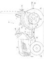
図1にはトラクタの全体側面が示されており、このトラクタは、機体前部に搭載されたエンジン21、エンジン21の後部に連結された主クラッチを内蔵したクラッチハウジング22、機体後部に配備されたミッションケース23、エンジン21からミッションケース23を経由した変速後の動力によって駆動可能な左右一対の前輪24、エンジン21からミッションケース23を経由した変速後の動力によって駆動される左右一対の後輪25、操向操作用のステアリングホイール26、左右の後輪25の間に配設された運転座席1、前輪24と後輪25の間に配設されたステップフロア2、及び、ステップフロア2の後部から左右の後輪25の上方を覆うように配設された後部フェンダ29などを備えて構成されている。
FIG. 1 shows an entire side surface of the tractor. The tractor is arranged at an
図1、図2に示すように、運転座席1を挟んだ左右一側部であるステップフロア2の右側部において、その前部箇所には、ミッションケース23の左右に連結される後車軸ケース30に内装された左右のブレーキ装置3(左サイドブレーキ装置3a、右サイドブレーキ装置3b)の操作アーム31に、回動支軸32や左右の第1ロッド33などを介して、各別に連係された左右のサイドブレーキペダル5a,5bからなる主ブレーキペダル5が左ブレーキペダル5aと右ブレーキペダル5bとが近接した状態で配備されており、これら左右のサイドブレーキペダル5a,5bのうちのいずれか一方のサイドブレーキペダル5のみを右足で踏み込み操作することによって、左右一方のブレーキ装置3のみを制動状態に操作できる。左右のサイドブレーキペダル5a,5bを図14に示すように係合ロック部材34で係合して左右双方のサイドブレーキペダル5a,5bを右足で同時に踏み込み操作することによって、左右のサイドブレーキ装置3a,3bを同時に制動状態に操作できる。右のサイドブレーキペダル5bの右横側には、エンジン21の動力を変速する静油圧式無段変速装置HST(図示せず)に連係された変速ペダル35が並設配備されており、この変速ペダル35の踏み込み量を右足で調節することによって調速操作を行えるようになっている。
As shown in FIG. 1 and FIG. 2, a
又、運転座席1を挟んだ左右他側部であるステップフロア2の左側部において、その前部箇所には、主クラッチに連係された主クラッチペダル12が配備されており、この主クラッチペダル12を左足で踏み込み操作することによって、エンジン21からミッションケース23への伝動を遮断する主クラッチの切り状態を現出できるようになっている。一方、その後部箇所となる左右の後部フェンダ29と座席下カバー36との間の凹入空間Sのうちの左側の凹入空間Sには、左右のサイドブレーキ装置3a,3bに連係されるとともに、左右のサイドブレーキ装置3a,3bを制動作用させる制動操作域で係合保持可能となるように構成された駐車ブレーキペダル8が、左の後部フェンダ29の下部前端位置よりも後方に位置する状態で配備されており、この駐車ブレーキペダル8を左足の踵で踏み込み操作して制動操作域で係合保持することによって、左右のサイドブレーキ装置3a,3bを制動作用状態に維持して駐車用のブレーキとして機能させる駐車ブレーキ状態を現出できるようになっている。
A main
機体の後部にはリフトアーム37の揺動に伴って、連結した作業機(図示せず)を昇降させるロアリンク38が設けられている。
A
本発明の実施の形態では、同じ左右のサイドブレーキ装置3a,3bに対して、左右のサイドブレーキペダル5a,5bが第1ロッド33や操作アーム31からなる第1連係機構4を介して連係されている。駐車ブレーキペダル8が操作アーム59、左側にのみ配置されたロッド62、回動軸60を介して連係された左右の中継揺動アーム61、第2ロッド63及び操作アーム31からなる第2連係機構7を介して連係されている。
In the embodiment of the present invention, the left and right
図1及び図2に示す後部フェンダ29の後部の符号71は、ブレーキランプである。ブレーキランプ71のスイッチ72はミッションケース23の側部に固定してあり、第1ロッド33に固定したブラケット73で押圧されている状態で切りの状態にある。ブレーキランプ71は左のサイドブレーキペダル5aを単独で、又は左右のサイドブレーキペダル5a,5bを同時に踏み操作されると点灯するように、第1連係機構4を構成する左側の第1ロッド33に対してのみこの左側の第1ロッド33の作動によりブレーキランプ71を点消灯させるブレーキスイッチ72を連係させ、前記駐車ブレーキペダル8の踏み込み及び戻し操作では前記ブレーキランプ71は点消灯させないで、左サイドブレーキペダル5aの踏み込み操作によりブレーキスイッチ72が入り作動してブレーキランプ71を点灯させ、左サイドブレーキペダル5aの戻し操作でブレーキスイッチ72が切り作動してブレーキランプ71を消灯させるように構成してある。
第1連係機構4と第2連係機構7は、それぞれ操作アーム31のブラケット65と左右のサイドブレーキペダル5a,5bに連係する第1ロッド33との間及びブラケット65と駐車ブレーキペダル8に連係する第2ロッド63との間に融通機構を設けてある。この融通機構は、左右のサイドブレーキペダル5a,5bを踏み込み操作したときは、第1ロッド33が前方に移動して後端のスペーサ66(第1接当部に相当する)を介して操作アーム31を図4の操作軸37の時計回りに揺動させるが、このとき駐車ブレーキペダル8に連係した第2ロッド63は移動しないで、ブラケット65がスペーサ67から離れて前方に移動するだけであり、ブラケット65とスペーサ67(第2接当部に相当する)との間に第1ロッド33が自由に動き得る融通(融通機構)をもたせてある。駐車ブレーキペダル8を踏み込み操作したときは、第2ロッド63が前方に移動して後端のスペーサ67を介して操作アーム31を図4の操作軸37の時計回りに揺動させるが、このとき左右のサイドブレーキペダル5a,5bに連係した第1ロッド33は移動しないで、ブラケット65がスペーサ66から離れて前方に移動するだけであり、ブラケット65とスペーサ66との間に第2ロッド63が自由に動き得る融通(融通機構)をもたせてある。
The
これにより、左のサイドブレーキペダル5a又は左右サイドブレーキブレーキペダル5a,5bを踏み込み操作したときは、駐車ブレーキペダル8を作動させないで左又は左右のサイドブレーキ装置3a,3bを制動作動させるとともに、ブレーキスイッチ72が作動してブレーキランプ71を点灯させる。駐車ブレーキペダル8を踏み込み操作したときには左右のサイドブレーキペダル5a,5bを作動させないで、左右のサイドブレーキ装置3a,3bを制動作動させるようになっている。
Thus, when the left
左右のサイドブレーキペダル5a,5bを運転部Aのステップフロア2における運転座席1を中心とした前部の右側に配置し、主クラッチ用の主クラッチペダル12をステップフロア2における運転座席1を中心とした前部の左側に配置し、駐車ブレーキペダル8を主クラッチペダル12の後方となる位置に配置してある。
The left and right
以上の構成から、機体の右側部に配備した左右のサイドブレーキペダル5a,5bを右足で同時に踏み込み操作して機体を走行停止させた後、機体の左側部に配備した駐車ブレーキペダル8を左足の踵で踏み込み操作することによって、機体を簡単に駐車させることができるようになっている。
From the above configuration, the left and right
又、駐車時に左右のサイドブレーキを操作するのに、踏み込み操作で左右のサイドブレーキの操作を行える駐車ブレーキペダル8を採用し、機体の左側部に形成されている凹入空間Sに駐車ブレーキペダル8を収めた状態で配備してあることから、駐車ブレーキペダル8を配備した左側部からのトラクタに対する乗降時や操縦時に駐車ブレーキペダル8が邪魔になることを回避でき、もって、駐車ブレーキペダル8を配備した左側部からのトラクタに対する乗降を行い易くすることができるとともに、駐車ブレーキペダル8を操縦者の足下に配備する駐車ブレーキペダル8としながらも居住性の向上を図れるようになっている。
In addition, a
しかも、駐車ブレーキペダル8を運転座席1を挟んだ左右のサイドブレーキペダル5a,5bの反対側に配備していることによって、上り坂や下り坂での駐車時には、右足による左右のサイドブレーキペダル5a,5bの同時踏み込み操作で走行停止状態を維持しながら、左足の踵による駐車ブレーキペダル8の踏み込み操作で左右のサイドブレーキの操作を行えることから、上り坂や下り坂でも安定した駐車ブレーキペダルの踏み込み操作を簡単に行えるようになっている。
Moreover, the
その上、機体を緊急停止させる必要が生じた場合には、左足の踵で駐車ブレーキペダル8を踏み込み操作することによって、機体を素早く緊急停止させることができるようになっている。
In addition, when it is necessary to stop the aircraft urgently, the aircraft can be quickly urgently stopped by depressing the
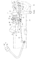
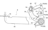
図3〜8に示すように、駐車ブレーキペダル8は、ミッションケース23の左側部に支持部材43を介して第一横軸芯P1周りに上下揺動自在に支持されたペダルアーム44、ペダルアーム44の遊端に固定されたペダル板45、下端をペダルアーム44の中間部外面に固設され上部を機体内側に折り曲げてペダルアーム44に対して垂直に上方に立設したストッパ部材46、ペダルアーム44の機体内側面に固定され、上縁に多数の係合凹部47を形成した係合板48、支持部材43とペダルアーム44の間に設けられてペダルアーム44を上昇方向に復帰付勢する付勢バネ49、支持部材43に固定した支軸50、支軸50に挿通された長孔51と係合板48の係合凹部47に係合する係止爪52とストッパピン53とを備えるとともに反転バネ54の一端部を取り付けた爪揺動部材55、及び、反転バネ54の他端部を取り付けるとともに駐車ブレーキペダル8の自由状態でペダルアーム44のストッパ部材46に押されて支持部材43に固定した支軸56による第2横軸芯P2周りに揺動し、爪揺動部材55のストッパピン53と係合して爪揺動部材55を支軸50による第3横軸芯P3周りに爪係合方向(図7の反時計方向)に付勢してペダルアーム44の位置決めをする位置決め揺動部材57、ペダルアーム44に第1横軸芯P1を形成する支軸58を介して一体揺動可能に連結された操作アーム59、第4横軸芯P4周りに回動軸60を介して一体揺動可能に連結された左右一対の中継揺動アーム61、操作アーム59と左側の中継揺動アーム61とに亘って架設されたロッド62、及び、左右の中継揺動アーム61と対応するサイドブレーキ装置3a,3bの操作アーム31とに亘って架設された第2ロッド63、などを介して左右のサイドブレーキ装置3a,3bに連係されている。操作アーム31にはサイドブレーキペダル5a,5bに連係している第1ロッド33と第2ロッド63を挿通するブラケット65を固設しており、ブラケット65に形成した2つの貫通穴に挿通した第1ロッド33と第2ロッド63の後部にそれぞれスペーサ66,67を介してダブルナット68,69で当接位置を調節できるようにしてある。ペダルアーム44は、駐車ブレーキペダル8の自由状態でストッパ部材46が位置決め揺動部材57に接当するとともに、爪揺動部材55の係止爪52が係合板48の係合凹部47に係合係止されることによって揺動規制されている。尚、図4に示す符号64は、左右の各サイドブレーキ装置3a,3bの操作アーム31を制動解除位置に復帰付勢する付勢バネである。
As shown in FIGS. 3 to 8, the
自由状態の制動解除姿勢に復帰している駐車ブレーキペダル8〔図9参照〕のペダル板45を左足の踵で踏み付けてペダルアーム44を下降させる、といった駐車ブレーキペダル8の踏み込み操作を行うと、図9から図10に示すようにペダル板45の踏み下げ操作が行われている間は、爪揺動部材55の係止爪52が反転バネ54の作用により係合板48の係合凹部47側に付勢された状態で係合凹部47の位置を順次移動しつつペダルアーム44が下降する。そして、所望の踏み込み位置まで踏み込み操作した段階で駐車ブレーキペダル8の前部位置から左足を離すと、付勢バネ49の作用によって係合凹部47に係合していた係止爪52が係合凹部47に圧接されて、係止爪52が第1横軸芯P1を中心に時計方向に回動させる作用力により、支軸50と長孔51の下端部で接当していた爪揺動部材55が揺動移動して長孔51の上端部と当接して係止爪52と係合凹部47との係合が保持された状態で固定される。この結果、駐車ブレーキペダル8が左右のサイドブレーキ装置3a,3bを制動作用させる制動操作域で係合保持されるようになる〔図11参照〕。つまり、駐車ブレーキペダル8の前部位置に対して左足による踏み込み操作を行うだけで、駐車ブレーキペダル8を制動操作域に係止保持する制動保持操作を簡単かつ確実に行えるようになっている。
When the
一方、駐車ブレーキペダル8が制動操作域で係止保持された状態において、駐車ブレーキペダル8におけるペダル板45を付勢バネ49に抗して左足の踵で再度踏み込み操作を行うと、ペダルアーム44の下降に伴って係止爪52が係合凹部47から離れ、反転バネ54の作用により爪揺動部材55が支軸56を中心に持ち上がって、支軸50に対して長孔51の上部に当接していた爪揺動部材55が長孔51の下部が当接する〔図12参照〕。その後ペダルアーム44を上昇させ、図13の状態から更に上昇して、ストッパ部材46により支軸56より上方の位置決め揺動部材57の前部端縁が押圧されると位置決め揺動部材57が支軸56の第2横軸芯P2を中心とする時計回りに揺動するに伴って、爪揺動部材55を第3横軸芯P3を中心とした反時計回りに揺動して係止爪52が係合凹部47に係合し、これにより駐車ブレーキペダル8が自由状態の位置での制動解除姿勢に復帰する〔図9参照〕。つまり、駐車ブレーキペダル8に対して左足による踏み込み操作を行うだけで、駐車ブレーキペダル8の制動操作域での係合保持を解除する制動解除操作を簡単かつ確実に行えるようになっている。
On the other hand, when the
要するに、左右のサイドブレーキ装置3a,3bを制動作用状態に維持して機体の駐車状態を現出する制動保持操作(駐車ブレーキ操作)と、左右のサイドブレーキ装置3a,3bの制動作用状態での維持を解除して機体の駐車状態を解除する制動解除操作(駐車ブレーキ解除操作)の双方を、左足のみによる駐車ブレーキペダル8の踏み込み操作を繰り返すだけで容易かつ確実に行えるようになっている。
駐車ブレーキペダル8による踏み込みの繰り返しだけで、左右のサイドブレーキ装置3a,3bの制動・制動解除を行う係合離脱機構を本発明ではペダル踏み込み式制動解除切換え機構と呼称する。
In short, the brake holding operation (parking brake operation) in which the left and right
In the present invention, an engagement / disengagement mechanism that performs braking / releasing of the left and right
〔別実施の形態〕
ブレーキスイッチ72は左右のサイドブレーキペダル5a,5bの操作系における少なくとも左右いずれか一方、即ち、上記実施形態とは逆に右の第1ロッド33に対してのみ設けてもよく、又、左右の第1ロッド33に設けたブレーキスイッチ72を並列回路で接続してもよい。
[Another embodiment]
The
1 運転座席
2 ステップフロア
3 ブレーキ装置
3a 左サイドブレーキ装置
3b 右サイドブレーキ装置
4 第1連係機構
5 主ブレーキペダル
5a 左サイドブレーキペダル
5b 右サイドブレーキペダル
7 第2連係機構
8 駐車ブレーキペダル
12 主クラッチペダル
23 ミッションケース
31 操作アーム
33 第1ロッド
63 第2ロッド
65 ブラケット
66 スペーサ(第1接当部)
67 スペーサ(第2接当部)
71 ブレーキランプ
72 ブレーキスイッチ
73 ブラケット(スイッチ操作用ブラケット)
A 運転部
1 driver's
23 Mission Case
31 Operation arm
33 First rod
63 2nd rod
65 Bracket
66 Spacer (First contact part)
67 Spacer (2nd contact part)
71
73 Bracket (Switch operation bracket)
A driving part
Claims (4)
前記ブレーキ装置を操作する操作アームにブラケットを設けて、このブラケットに前後に貫通する2つの貫通穴を形成し、前記2つの貫通穴のうちの一方の貫通穴に前記第1連係機構を構成する第1ロッドの後端側を挿通して、前記ブラケットの後側に位置する前記第1ロッドの後端部に第1接当部を連結し、前記2つの貫通穴のうちの他方の貫通穴に前記第2連係機構を構成する第2ロッドの後端側を挿通して、前記ブラケットの後側に位置する前記第2ロッドの後端部に第2接当部を連結し、
前記主ブレーキペダルを踏み込み操作して前記第1ロッドを引き操作したときには、前記他方の貫通穴による融通によって前記駐車ブレーキペダルを作動させないで、前記第1接当部を介して前記操作アームを揺動させて前記ブレーキ装置を制動作動させるとともに、前記ブレーキスイッチが作動してブレーキランプを点灯させ、且つ、前記駐車ブレーキペダルを踏み込み操作して前記第2ロッドを引き操作したときには、前記一方の貫通穴による融通によって前記主ブレーキペダルを作動させないで、前記第2接当部を介して前記操作アームを揺動させて前記ブレーキ装置を制動作動させるように構成してあるトラクタにおけるブレーキランプの点灯操作構造。 A main brake pedal linked to the same brake device via the first linkage mechanism and a parking brake pedal linked via the second linkage mechanism to the operating portion of the tractor traveling machine body are provided, and the main brake pedal and the parking The brake pedal is configured to be operated in a braking state by individually depressing the brake pedal, and the brake lamp is turned on only by the operation of the first linkage mechanism only with respect to the first linkage mechanism. is linked to a brake switch for turning off, the parking is in depression and the return operation of the brake pedal is not turned off point the brake lamp, wherein in the brake switch enters actuated to light the brake lamp by depression of the main brake pedal, the brake switch in the returning operation of the main brake pedal Actuated configured to turn off the brake lamp Ri,
A bracket is provided on an operating arm for operating the brake device, two through holes are formed through the bracket in the front-rear direction, and the first linkage mechanism is configured in one of the two through holes. A rear end side of the first rod is inserted, a first contact portion is connected to a rear end portion of the first rod located on the rear side of the bracket, and the other through hole of the two through holes The second rod constituting the second linkage mechanism is inserted through the rear end side of the second rod, the second contact portion is coupled to the rear end portion of the second rod located on the rear side of the bracket,
When the first brake is operated by depressing the main brake pedal, the parking brake pedal is not actuated by the accommodation through the other through hole, and the operation arm is swung through the first contact portion. When the brake device is actuated to actuate the brake, the brake switch is actuated to light the brake lamp, and the parking brake pedal is depressed to pull the second rod. Lighting operation of a brake lamp in a tractor configured to actuate the brake device by swinging the operation arm via the second contact portion without operating the main brake pedal due to accommodation by a hole Construction.
Priority Applications (2)
| Application Number | Priority Date | Filing Date | Title |
|---|---|---|---|
| JP2008034679A JP4673385B2 (en) | 2008-02-15 | 2008-02-15 | Brake lamp lighting operation structure in tractor |
| FR0858397A FR2927595B1 (en) | 2008-02-15 | 2008-12-09 | TRACTOR BRAKE SYSTEM |
Applications Claiming Priority (1)
| Application Number | Priority Date | Filing Date | Title |
|---|---|---|---|
| JP2008034679A JP4673385B2 (en) | 2008-02-15 | 2008-02-15 | Brake lamp lighting operation structure in tractor |
Publications (2)
| Publication Number | Publication Date |
|---|---|
| JP2009190615A JP2009190615A (en) | 2009-08-27 |
| JP4673385B2 true JP4673385B2 (en) | 2011-04-20 |
Family
ID=41073015
Family Applications (1)
| Application Number | Title | Priority Date | Filing Date |
|---|---|---|---|
| JP2008034679A Active JP4673385B2 (en) | 2008-02-15 | 2008-02-15 | Brake lamp lighting operation structure in tractor |
Country Status (1)
| Country | Link |
|---|---|
| JP (1) | JP4673385B2 (en) |
Families Citing this family (2)
| Publication number | Priority date | Publication date | Assignee | Title |
|---|---|---|---|---|
| JP5337113B2 (en) * | 2010-07-28 | 2013-11-06 | 株式会社クボタ | Tractor |
| JP6374766B2 (en) * | 2014-11-12 | 2018-08-15 | 三菱マヒンドラ農機株式会社 | Work vehicle |
Citations (9)
| Publication number | Priority date | Publication date | Assignee | Title |
|---|---|---|---|---|
| JPS53118246U (en) * | 1977-02-28 | 1978-09-20 | ||
| JPS55149629U (en) * | 1979-04-14 | 1980-10-28 | ||
| JPS5687945U (en) * | 1979-12-11 | 1981-07-14 | ||
| JPS57130839A (en) * | 1981-02-06 | 1982-08-13 | Iseki & Co Ltd | Stop light illuminating device |
| JPH0564252U (en) * | 1992-02-05 | 1993-08-27 | 株式会社クボタ | Forward and backward operation device for tractor |
| JPH06146342A (en) * | 1992-11-02 | 1994-05-27 | Iseki & Co Ltd | Front hood |
| JPH07205774A (en) * | 1994-01-17 | 1995-08-08 | Kubota Corp | Brake device for work vehicle |
| JPH11139274A (en) * | 1997-11-11 | 1999-05-25 | Seirei Ind Co Ltd | Brake device for running vehicle |
| JPH11321594A (en) * | 1998-05-11 | 1999-11-24 | Kubota Corp | Brake operation structure for tractor |
-
2008
- 2008-02-15 JP JP2008034679A patent/JP4673385B2/en active Active
Patent Citations (9)
| Publication number | Priority date | Publication date | Assignee | Title |
|---|---|---|---|---|
| JPS53118246U (en) * | 1977-02-28 | 1978-09-20 | ||
| JPS55149629U (en) * | 1979-04-14 | 1980-10-28 | ||
| JPS5687945U (en) * | 1979-12-11 | 1981-07-14 | ||
| JPS57130839A (en) * | 1981-02-06 | 1982-08-13 | Iseki & Co Ltd | Stop light illuminating device |
| JPH0564252U (en) * | 1992-02-05 | 1993-08-27 | 株式会社クボタ | Forward and backward operation device for tractor |
| JPH06146342A (en) * | 1992-11-02 | 1994-05-27 | Iseki & Co Ltd | Front hood |
| JPH07205774A (en) * | 1994-01-17 | 1995-08-08 | Kubota Corp | Brake device for work vehicle |
| JPH11139274A (en) * | 1997-11-11 | 1999-05-25 | Seirei Ind Co Ltd | Brake device for running vehicle |
| JPH11321594A (en) * | 1998-05-11 | 1999-11-24 | Kubota Corp | Brake operation structure for tractor |
Also Published As
| Publication number | Publication date |
|---|---|
| JP2009190615A (en) | 2009-08-27 |
Similar Documents
| Publication | Publication Date | Title |
|---|---|---|
| JP2003072528A (en) | Riding mower | |
| JP2007055281A (en) | Travel speed operation device | |
| JP2017039339A (en) | Working vehicle | |
| JP4764437B2 (en) | Brake operation mechanism of tractor | |
| JP4673385B2 (en) | Brake lamp lighting operation structure in tractor | |
| US9174613B2 (en) | Vehicle speed operating device for work vehicle | |
| JP5337113B2 (en) | Tractor | |
| JP4733555B2 (en) | Shifting structure of work equipment | |
| JP3717304B2 (en) | Brake operation structure of tractor | |
| JPH02120571A (en) | Controller for car | |
| JP2011109993A (en) | Riding rice transplanter | |
| JP5764074B2 (en) | Brake control tool for work vehicle | |
| JP2013067231A (en) | Operating device of tractor | |
| JP4263062B2 (en) | Shifting operation structure of work vehicle | |
| WO2006027940A1 (en) | Traveling operation device and work vehicle | |
| JP3776035B2 (en) | Agricultural machine | |
| JP4749967B2 (en) | Traveling operation device for work vehicle | |
| EP1792796A1 (en) | Brake operating device of traveling vehicle | |
| JP4454170B2 (en) | Steering device of rice transplanter | |
| JP4164063B2 (en) | Steering lock device for passenger-type traveling vehicle | |
| JP6514029B2 (en) | Work vehicle | |
| JP5391161B2 (en) | Switching operation device | |
| JP4164062B2 (en) | Ground control tools for passenger-type traveling vehicles | |
| JP2014082980A (en) | Ground operation tool in sulky type traveling vehicle | |
| JP2015123760A (en) | Service car |
Legal Events
| Date | Code | Title | Description |
|---|---|---|---|
| A621 | Written request for application examination |
Free format text: JAPANESE INTERMEDIATE CODE: A621 Effective date: 20100316 |
|
| A977 | Report on retrieval |
Free format text: JAPANESE INTERMEDIATE CODE: A971007 Effective date: 20100728 |
|
| A131 | Notification of reasons for refusal |
Free format text: JAPANESE INTERMEDIATE CODE: A131 Effective date: 20100805 |
|
| A521 | Written amendment |
Free format text: JAPANESE INTERMEDIATE CODE: A523 Effective date: 20101004 |
|
| TRDD | Decision of grant or rejection written | ||
| A01 | Written decision to grant a patent or to grant a registration (utility model) |
Free format text: JAPANESE INTERMEDIATE CODE: A01 Effective date: 20101222 |
|
| A01 | Written decision to grant a patent or to grant a registration (utility model) |
Free format text: JAPANESE INTERMEDIATE CODE: A01 |
|
| A61 | First payment of annual fees (during grant procedure) |
Free format text: JAPANESE INTERMEDIATE CODE: A61 Effective date: 20110120 |
|
| R150 | Certificate of patent or registration of utility model |
Ref document number: 4673385 Country of ref document: JP Free format text: JAPANESE INTERMEDIATE CODE: R150 Free format text: JAPANESE INTERMEDIATE CODE: R150 |
|
| FPAY | Renewal fee payment (event date is renewal date of database) |
Free format text: PAYMENT UNTIL: 20140128 Year of fee payment: 3 |