JP4670406B2 - Temperature compensated piezoelectric oscillator - Google Patents
Temperature compensated piezoelectric oscillator Download PDFInfo
- Publication number
- JP4670406B2 JP4670406B2 JP2005066395A JP2005066395A JP4670406B2 JP 4670406 B2 JP4670406 B2 JP 4670406B2 JP 2005066395 A JP2005066395 A JP 2005066395A JP 2005066395 A JP2005066395 A JP 2005066395A JP 4670406 B2 JP4670406 B2 JP 4670406B2
- Authority
- JP
- Japan
- Prior art keywords
- temperature
- voltage
- low
- order
- generates
- Prior art date
- Legal status (The legal status is an assumption and is not a legal conclusion. Google has not performed a legal analysis and makes no representation as to the accuracy of the status listed.)
- Active
Links
- 230000015572 biosynthetic process Effects 0.000 claims description 42
- 238000003786 synthesis reaction Methods 0.000 claims description 42
- 230000010355 oscillation Effects 0.000 claims description 27
- 230000002194 synthesizing effect Effects 0.000 claims description 24
- 238000001514 detection method Methods 0.000 claims description 12
- 230000000903 blocking effect Effects 0.000 claims description 9
- 230000007423 decrease Effects 0.000 claims description 9
- 238000010586 diagram Methods 0.000 description 27
- 239000013078 crystal Substances 0.000 description 23
- 239000003990 capacitor Substances 0.000 description 11
- 238000012886 linear function Methods 0.000 description 10
- 230000001747 exhibiting effect Effects 0.000 description 7
- 238000005094 computer simulation Methods 0.000 description 6
- 230000035945 sensitivity Effects 0.000 description 6
- 238000007796 conventional method Methods 0.000 description 2
- 238000012888 cubic function Methods 0.000 description 2
- 238000000034 method Methods 0.000 description 1
- 230000000630 rising effect Effects 0.000 description 1
- 238000004088 simulation Methods 0.000 description 1
- 239000007787 solid Substances 0.000 description 1
Images


Classifications
-
- H—ELECTRICITY
- H03—ELECTRONIC CIRCUITRY
- H03B—GENERATION OF OSCILLATIONS, DIRECTLY OR BY FREQUENCY-CHANGING, BY CIRCUITS EMPLOYING ACTIVE ELEMENTS WHICH OPERATE IN A NON-SWITCHING MANNER; GENERATION OF NOISE BY SUCH CIRCUITS
- H03B5/00—Generation of oscillations using amplifier with regenerative feedback from output to input
- H03B5/30—Generation of oscillations using amplifier with regenerative feedback from output to input with frequency-determining element being electromechanical resonator
- H03B5/32—Generation of oscillations using amplifier with regenerative feedback from output to input with frequency-determining element being electromechanical resonator being a piezoelectric resonator
-
- H—ELECTRICITY
- H03—ELECTRONIC CIRCUITRY
- H03L—AUTOMATIC CONTROL, STARTING, SYNCHRONISATION, OR STABILISATION OF GENERATORS OF ELECTRONIC OSCILLATIONS OR PULSES
- H03L1/00—Stabilisation of generator output against variations of physical values, e.g. power supply
- H03L1/02—Stabilisation of generator output against variations of physical values, e.g. power supply against variations of temperature only
- H03L1/022—Stabilisation of generator output against variations of physical values, e.g. power supply against variations of temperature only by indirect stabilisation, i.e. by generating an electrical correction signal which is a function of the temperature
- H03L1/023—Stabilisation of generator output against variations of physical values, e.g. power supply against variations of temperature only by indirect stabilisation, i.e. by generating an electrical correction signal which is a function of the temperature by using voltage variable capacitance diodes
-
- H—ELECTRICITY
- H03—ELECTRONIC CIRCUITRY
- H03B—GENERATION OF OSCILLATIONS, DIRECTLY OR BY FREQUENCY-CHANGING, BY CIRCUITS EMPLOYING ACTIVE ELEMENTS WHICH OPERATE IN A NON-SWITCHING MANNER; GENERATION OF NOISE BY SUCH CIRCUITS
- H03B5/00—Generation of oscillations using amplifier with regenerative feedback from output to input
- H03B5/02—Details
- H03B5/04—Modifications of generator to compensate for variations in physical values, e.g. power supply, load, temperature
-
- H—ELECTRICITY
- H03—ELECTRONIC CIRCUITRY
- H03B—GENERATION OF OSCILLATIONS, DIRECTLY OR BY FREQUENCY-CHANGING, BY CIRCUITS EMPLOYING ACTIVE ELEMENTS WHICH OPERATE IN A NON-SWITCHING MANNER; GENERATION OF NOISE BY SUCH CIRCUITS
- H03B5/00—Generation of oscillations using amplifier with regenerative feedback from output to input
- H03B5/30—Generation of oscillations using amplifier with regenerative feedback from output to input with frequency-determining element being electromechanical resonator
- H03B5/32—Generation of oscillations using amplifier with regenerative feedback from output to input with frequency-determining element being electromechanical resonator being a piezoelectric resonator
- H03B5/36—Generation of oscillations using amplifier with regenerative feedback from output to input with frequency-determining element being electromechanical resonator being a piezoelectric resonator active element in amplifier being semiconductor device
- H03B5/366—Generation of oscillations using amplifier with regenerative feedback from output to input with frequency-determining element being electromechanical resonator being a piezoelectric resonator active element in amplifier being semiconductor device and comprising means for varying the frequency by a variable voltage or current
- H03B5/368—Generation of oscillations using amplifier with regenerative feedback from output to input with frequency-determining element being electromechanical resonator being a piezoelectric resonator active element in amplifier being semiconductor device and comprising means for varying the frequency by a variable voltage or current the means being voltage variable capacitance diodes
-
- H—ELECTRICITY
- H03—ELECTRONIC CIRCUITRY
- H03L—AUTOMATIC CONTROL, STARTING, SYNCHRONISATION, OR STABILISATION OF GENERATORS OF ELECTRONIC OSCILLATIONS OR PULSES
- H03L1/00—Stabilisation of generator output against variations of physical values, e.g. power supply
- H03L1/02—Stabilisation of generator output against variations of physical values, e.g. power supply against variations of temperature only
- H03L1/028—Stabilisation of generator output against variations of physical values, e.g. power supply against variations of temperature only of generators comprising piezoelectric resonators
Description
本発明は水晶等の圧電素子を使用した発振器に関し、特に簡単な回路構成によって周波数の温度補償が可能で、且つIC化に適した温度補償型圧電発振器に関するものである。 The present invention relates to an oscillator using a piezoelectric element such as a crystal, and more particularly to a temperature-compensated piezoelectric oscillator capable of temperature compensation of a frequency with a simple circuit configuration and suitable for an IC.
近年、圧電素子、例えば水晶振動子を使用した発振器では周波数安定度は勿論のこと、小型化、低価格化等の要求が厳しく、更には、通信方式のデジタル化が進むにつれて、従来問題とならなかった雑音比特性(C/N特性)の向上が望まれている。発振器の出力周波数は種々の要因で変化するが、比較的周波数の安定度が高い水晶発振器においても、周囲温度、電源電圧及び出力負荷等の条件変化による周波数変動があり、これ等に対応する手段は種々のものが講じられている。例えば温度変化に関しては水晶発振器に温度補償回路を付加し、発振ループ中の負荷容量を変化させて、水晶振動子固有の温度−周波数特性を相殺するように前記負荷容量を温度変化に対して制御した温度補償水晶発振器(以下、TCXOと称す)がある。
図15(a)は、同一出願人により考え出されたTCXOの回路図である。この例に示すTCXOは、コルピッツ発振回路60に、直流阻止用固定容量素子C3と、温度補償回路61と、水晶振動子Xとを直列に接続したものである。この温度補償回路61は、低温部補償用MOS容量素子MLと感度調整用固定容量素子C4との直列接続回路と、高温部補償用MOS容量素子MHとの並列接続からなっており、低温用MOS容量素子MLと高温用MOS容量素子MHが互いに異なる極性の向きとなっている。また、低温用MOS容量素子MLのアノード端子側と固定容量素子C4との接続中点には、低温部制御電圧信号VLが入力抵抗R4を介して供給されていて、高温用MOS容量素子MHのゲート端子側には入力抵抗R5を介して高温部制御電圧信号VHが供給されている。そして、この低温用MOS容量素子MLのゲート端子側と高温用MOS容量素子MHのアノード端子側には基準電圧信号VREFが入力抵抗R6を介して供給されている。
図15(b)はTCXOの温度補償電圧の図である。本発明のTCXOの温度補償はMOSバラクタを利用して振動子Xの周波数温度補償を行っている。MOS型バラクタの温度変化に対する容量変化が3次関数に近いため、MOS型バラクタに加える電圧が温度変化に対して1次関数的に変化するもののみで温度補償を実現できる。しかし、水晶振動子の周波数温度特性は固体間でバラツキがあるためMOS容量変化が温度補償を行うと必ずしも理想的な補償カーブでなく、温度補償精度はあまり良くなかったため高い周波数安定度をもつ基準発振源を必要とする、例えばGPS受信機用の基準発振器としては十分な性能ではなかった。
図16(b)は図15のTCXOの温度特性を示す図である。図16(a)の実線62は水晶振動子Xの温度特性を示し、破線63は温度補償回路61を図15(b)に示す制御電圧にて制御した場合の温度変化に対する周波数可変特性を示す。この図から明らかな通り、図15(b)に示すような制御電圧にて温度補償回路61を制御した場合、周波数の曲線的な変化を必要とする部分における曲率を微調整することができなかったので、水晶振動子Xの温度特性62を補償するには理想的な補償制御ができなく(補償カーブが得られなく)、温度補償後の温度特性の精度は±2ppmしか得られなかった。
FIG. 15A is a circuit diagram of a TCXO conceived by the same applicant. The TCXO shown in this example is obtained by connecting a
FIG. 15B is a diagram of the temperature compensation voltage of the TCXO. In the temperature compensation of the TCXO of the present invention, the frequency temperature compensation of the vibrator X is performed using a MOS varactor. Since the capacitance change with respect to the temperature change of the MOS varactor is close to a cubic function, the temperature compensation can be realized only by the voltage applied to the MOS varactor changing in a linear function with respect to the temperature change. However, since the frequency temperature characteristics of crystal units vary between solids, MOS capacitance change is not necessarily an ideal compensation curve when temperature compensation is performed, and the temperature compensation accuracy was not so good, so the standard has high frequency stability. For example, a reference oscillator for a GPS receiver that requires an oscillation source is not sufficient.
FIG. 16B is a diagram showing temperature characteristics of the TCXO of FIG. A
特許文献1に開示されている従来技術は、MOS型バラクタの非線型性な容量変化が3次関数に近いため、MOS型バラクタに加える電圧が単純な1次関数のみで温度補償を実現できるが、理想的な補償カーブでないため、温度補償精度はあまり良くなかった。
また高温部のMOSバラクタMHは低温では周波数感度がないことが理想的であるが、実際はわずかに周波数感度を持っており、高温の制御電圧VHは低温部でも影響を与える。従って、高精度な周波数安定度が要求される製品の場合、特定の周波数温度特性を持つ水晶振動子を選別しなければならないなど周波数の調整が複雑になるといった問題がある。
本発明は、かかる課題に鑑み、MOS型バラクタの非線型性な容量変化を利用して温度補償回路の補償容量カーブを理想的なものに近づけるため、直線的な制御電圧の特性に高次関数特性を合成して温度補償精度を向上したTCXOを提供することを目的とする。
また他の目的は、低温部と高温部の制御電圧が影響し合わないようにするために、低温部の制御電圧を常温以上で一定値にし、高温部の制御電圧を常温以下で一定値にして高精度製品の場合であっても周波数の調整を容易とすることである。
In the prior art disclosed in
Ideally, the MOS varactor MH in the high temperature part has no frequency sensitivity at a low temperature, but actually has a slight frequency sensitivity, and the control voltage VH at a high temperature also affects the low temperature part. Therefore, in the case of a product that requires high-accuracy frequency stability, there is a problem that frequency adjustment becomes complicated, for example, it is necessary to select a crystal resonator having a specific frequency temperature characteristic.
In view of such a problem, the present invention uses a nonlinear capacitance change of a MOS varactor to approximate the compensation capacitance curve of the temperature compensation circuit to an ideal one. An object of the present invention is to provide a TCXO with improved temperature compensation accuracy by combining characteristics.
Another purpose is to keep the control voltage of the low temperature part and the high temperature part from affecting each other, so that the control voltage of the low temperature part is constant above normal temperature and the control voltage of high temperature part is constant below normal temperature. Therefore, even in the case of a high-precision product, it is easy to adjust the frequency.
本発明はかかる課題を解決するために、請求項1は、圧電素子に電流を流して励振させる発振回路と、直流阻止用固定容量素子と、温度変化による発振周波数の変化を補償する周波数温度補償回路と、所定の周波数で励振される圧電素子を備えた圧電振動子と、を有する温度補償型圧電発振器であって、前記周波数温度補償回路は、周囲温度によりパラメータが変化する温度検出部により変化したパラメータに基づいて電圧を発生する温度補償用電圧発生部を備え、前記温度補償用電圧発生部は、前記圧電素子の温度特性の常温を中心として低温側の温度特性を補償する電圧を発生する低温制御電圧発生部と、高温側の温度特性を補償する電圧を発生する高温制御電圧発生部とを備え、前記低温制御電圧発生部は、温度に対して直線的に変化する電圧を生成する低温1次電圧生成手段と、該低温1次電圧生成手段により生成された電圧の低温側の温度に対して高次の次数を持つ電圧を生成する低温高次電圧生成手段と、前記低温1次電圧生成手段及び低温高次電圧生成手段により生成される電圧を合成する低温電圧合成手段とを備え、前記温度補償用電圧発生部は、低温時には、前記高温制御電圧発生部の前記低温時における出力電圧の変化により生じる前記発振周波数の変動を補償するように、前記低温高次電圧生成手段を設定することを特徴とする。
本発明は直線的な制御電圧を用いて温度補償を行っていた従来の方式に対して、可能な限りMOS型バラクタの特性を水晶振動子の特性に近づけるために、直線的な制御電圧と高次の次数を持つ電圧を合成するものである。即ち、低温側に対しては低温側の温度で高次の次数を持つ電圧を生成するようにし、高温側に対しては高温側の温度で高次の次数を持つ電圧を生成するようにした高次電圧生成手段をそれぞれ備え、直線的な制御電圧と合成することにより低温側と高温側の制御電圧を生成して温度補償回路に印加するものである。
In order to solve the above-mentioned problems, the present invention provides an oscillation circuit that excites a piezoelectric element by passing a current, a DC blocking fixed capacitor element, and a frequency temperature compensation that compensates for a change in oscillation frequency due to a temperature change. A temperature-compensated piezoelectric oscillator having a circuit and a piezoelectric vibrator having a piezoelectric element excited at a predetermined frequency, wherein the frequency-temperature-compensating circuit is changed by a temperature detection unit whose parameters change according to the ambient temperature. And a temperature compensation voltage generator that generates a voltage based on the parameters, and the temperature compensation voltage generator generates a voltage that compensates for the temperature characteristics of the low temperature side centered on the temperature characteristics of the piezoelectric element. A low-temperature control voltage generator, and a high-temperature control voltage generator that generates a voltage that compensates for temperature characteristics on the high temperature side, and the low-temperature control voltage generator varies linearly with respect to temperature. Low temperature primary voltage generating means for generating a voltage, and low temperature high order voltage generating means for generating a voltage having a higher order with respect to the temperature on the low temperature side of the voltage generated by the low temperature primary voltage generating means; A low-temperature voltage synthesis unit that synthesizes the voltages generated by the low-temperature primary voltage generation unit and the low-temperature high-order voltage generation unit, and the temperature compensation voltage generation unit is configured to The low-temperature high-order voltage generation means is set so as to compensate for fluctuations in the oscillation frequency caused by changes in the output voltage at the low temperature .
In contrast to the conventional method in which temperature compensation is performed using a linear control voltage, the present invention provides a linear control voltage and a high voltage in order to make the characteristics of the MOS varactor as close as possible to the characteristics of a crystal resonator. A voltage having the following order is synthesized. That is, for the low temperature side, a voltage having a higher order at a temperature on the low temperature side is generated, and for the high temperature side, a voltage having a higher order at a temperature on the high temperature side is generated. High-order voltage generation means are provided, respectively, and by combining with a linear control voltage, a low-temperature side and a high-temperature side control voltage are generated and applied to the temperature compensation circuit.
請求項2は、圧電素子に電流を流して励振させる発振回路と、直流阻止用固定容量素子と、温度変化による発振周波数の変化を補償する周波数温度補償回路と、所定の周波数で励振される圧電素子を備えた圧電振動子と、を有する温度補償型圧電発振器であって、前記周波数温度補償回路は、周囲温度によりパラメータが変化する温度検出部により変化したパラメータに基づいて電圧を発生する温度補償用電圧発生部を備え、前記温度補償用電圧発生部は、前記圧電素子の温度特性の常温を中心として低温側の温度特性を補償する電圧を発生する低温制御電圧発生部と、高温側の温度特性を補償する電圧を発生する高温制御電圧発生部とを備え、前記高温制御電圧発生部は、温度に対して直線的に変化する電圧を生成する高温1次電圧生成手段と、該高温1次電圧生成手段により生成された電圧の高温側の温度に対して高次の次数を持つ電圧を生成する高温高次電圧生成手段と、前記高温1次電圧生成手段及び高温高次電圧生成手段により生成される電圧を合成する高温電圧合成手段とを備え、前記温度補償用電圧発生部は、高温時には、前記低温制御電圧発生部の前記高温時における出力電圧の変化により生じる前記発振周波数の変動を補償するように、前記高温高次電圧生成手段を設定することを特徴とする。
本発明は直線的な制御電圧を用いて温度補償を行っていた従来の方式に対して、可能な限りMOS型バラクタの特性を水晶振動子の特性に近づけるために、2種類の直線的な制御電圧を合成するものである。即ち、低温側に対しては勾配が異なる2種類の直線的な制御電圧を生成するようにし、高温側に対しては勾配が異なる2種類の直線的な制御電圧を生成するようにし、これらの2種類の直線的な制御電圧をそれぞれ合成することにより、低温側と高温側の制御電圧を生成して温度補償回路に印加するものである。
According to a second aspect of the present invention, there is provided an oscillation circuit for exciting a piezoelectric element by passing a current, a DC blocking fixed capacitance element, a frequency temperature compensation circuit for compensating for a change in oscillation frequency due to a temperature change, and a piezoelectric excited at a predetermined frequency. A temperature compensation type piezoelectric oscillator having a piezoelectric vibrator having an element, wherein the frequency temperature compensation circuit generates a voltage based on a parameter changed by a temperature detection unit whose parameter changes according to an ambient temperature. The temperature compensation voltage generator includes a low-temperature control voltage generator that generates a voltage that compensates for a low-temperature temperature characteristic centered on a normal temperature of the temperature characteristics of the piezoelectric element, and a high-temperature temperature. A high-temperature control voltage generator that generates a voltage that compensates for characteristics, and the high-temperature control voltage generator generates a voltage that changes linearly with respect to temperature. A high-temperature high-order voltage generating means for generating a voltage having a higher order with respect to the temperature on the high-temperature side of the voltage generated by the high-temperature primary voltage generating means; the high-temperature primary voltage generating means; High temperature voltage synthesizing means for synthesizing the voltage generated by the secondary voltage generating means, and the temperature compensation voltage generator is generated by a change in output voltage at the high temperature of the low temperature control voltage generator when the temperature is high. The high-temperature high-order voltage generation means is set so as to compensate for fluctuations in the oscillation frequency .
In the present invention, two types of linear control are performed in order to make the characteristics of the MOS varactor as close as possible to the characteristics of the crystal resonator, as compared with the conventional method in which temperature compensation is performed using a linear control voltage. The voltage is synthesized. That is, two types of linear control voltages with different gradients are generated for the low temperature side, and two types of linear control voltages with different gradients are generated for the high temperature side. By synthesizing two kinds of linear control voltages, a low-temperature side control voltage and a high-temperature side control voltage are generated and applied to the temperature compensation circuit.
請求項3は、圧電素子に電流を流して励振させる発振回路と、直流阻止用固定容量素子と、温度変化による発振周波数の変化を補償する周波数温度補償回路と、所定の周波数で励振される圧電素子を備えた圧電振動子と、を有する温度補償型圧電発振器であって、前記周波数温度補償回路は、周囲温度によりパラメータが変化する温度検出部により変化したパラメータに基づいて電圧を発生する温度補償用電圧発生部を備え、前記温度補償用電圧発生部は、前記圧電素子の温度特性の常温を中心として低温側の温度特性を補償する電圧を発生する低温制御電圧発生部と、高温側の温度特性を補償する電圧を発生する高温制御電圧発生部とを備え、前記低温制御電圧発生部は、温度に対して直線的に変化する電圧を生成する低温1次電圧生成手段と、該低温1次電圧生成手段により生成された電圧の低温側の温度に対して高次の次数を持つ電圧を生成する低温高次電圧生成手段と、前記低温1次電圧生成手段及び低温高次電圧生成手段により生成される電圧を合成する低温電圧合成手段とを備え、前記高温制御電圧発生部は、温度に対して直線的に変化する電圧を生成する高温1次電圧生成手段と、該高温1次電圧生成手段により生成された電圧の高温側の温度に対して高次の次数を持つ電圧を生成する高温高次電圧生成手段と、前記高温1次電圧生成手段及び高温高次電圧生成手段により生成される電圧を合成する高温電圧合成手段とを備え、前記温度補償用電圧発生部は、低温時には、前記高温制御電圧発生部の前記低温時における出力電圧の変化により生じる前記発振周波数の変動を補償するように、前記低温高次電圧生成手段を設定し、高温時には、前記低温制御電圧発生部の前記高温時における出力電圧の変化により生じる前記発振周波数の変動を補償するように、前記高温高次電圧生成手段を設定することを特徴とする。
本発明は更に正確な高次の電圧を生成するために、3種類のセンサ電圧を高次電圧生成手段(差動増幅器)に入力して高次電流を生成し、その電流を電圧に変換し、1次電圧生成手段による電圧と合成することにより制御電圧を発生させるものである。
According to a third aspect of the present invention, there is provided an oscillation circuit that excites a piezoelectric element by passing a current, a DC blocking fixed capacitor element, a frequency temperature compensation circuit that compensates for a change in oscillation frequency due to a temperature change, and a piezoelectric element that is excited at a predetermined frequency. A temperature compensation type piezoelectric oscillator having a piezoelectric vibrator having an element, wherein the frequency temperature compensation circuit generates a voltage based on a parameter changed by a temperature detection unit whose parameter changes according to an ambient temperature. The temperature compensation voltage generator includes a low-temperature control voltage generator that generates a voltage that compensates for a low-temperature temperature characteristic centered on a normal temperature of the temperature characteristics of the piezoelectric element, and a high-temperature temperature. A high temperature control voltage generator that generates a voltage that compensates for the characteristics, and the low temperature control voltage generator generates a voltage that changes linearly with respect to temperature. A low-temperature high-order voltage generating means for generating a voltage having a high-order with respect to the temperature on the low-temperature side of the voltage generated by the low-temperature primary voltage generating means, the low-temperature primary voltage generating means, and the low-temperature high-voltage Low-temperature voltage synthesis means for synthesizing the voltage generated by the secondary voltage generation means, the high-temperature control voltage generation unit, high-temperature primary voltage generation means for generating a voltage that varies linearly with respect to temperature, High-temperature high-order voltage generation means for generating a voltage having a higher order with respect to the temperature on the high-temperature side of the voltage generated by the high-temperature primary voltage generation means, the high-temperature primary voltage generation means, and the high-temperature high-order voltage generation and a high-temperature voltage synthesizing means for synthesizing the voltage generated by means, said temperature compensation voltage generation unit, during a low temperature, the oscillation frequency caused by a change in the output voltage at the low temperature of the high temperature control voltage generation unit The low-temperature high-order voltage generating means is set so as to compensate for dynamics, and at high temperatures, the low-frequency control voltage generator is compensated for fluctuations in the oscillation frequency caused by changes in the output voltage at high temperatures. A high-temperature high-order voltage generation means is set .
In order to generate a more accurate high-order voltage, the present invention inputs three types of sensor voltages to a high-order voltage generation means (differential amplifier) to generate a high-order current and converts the current into a voltage. The control voltage is generated by synthesizing with the voltage generated by the primary voltage generating means.
請求項4は、圧電素子に電流を流して励振させる発振回路と、直流阻止用固定容量素子と、温度変化による発振周波数の変化を補償する周波数温度補償回路と、所定の周波数で励振される圧電素子を備えた圧電振動子と、を有する温度補償型圧電発振器であって、前記周波数温度補償回路は、周囲温度によりパラメータが変化する温度検出部により変化したパラメータに基づいて電圧を発生する温度補償用電圧発生部を備え、前記温度検出部は、低温から温度が上昇するに従って直線的に上昇する電圧を発生する第1のセンサ電圧発生回路と、低温から温度が上昇するに従って直線的に下降する電圧を発生する第2のセンサ電圧発生回路と、低温から温度が上昇するに従って直線的に上昇する電圧を発生する第3のセンサ電圧発生回路と、を備え、 前記温度補償用電圧発生部は、前記圧電素子の温度特性の常温を中心として低温側の温度特性を補償する電圧を発生する低温制御電圧発生部と、高温側の温度特性を補償する電圧を発生する高温制御電圧発生部とを備え、前記低温制御電圧発生部は、前記第2のセンサ電圧に基づいて直線的に変化する電圧を生成する低温1次電圧生成手段と、前記第2のセンサ電圧及び前記第3のセンサ電圧に基づいて前記低温1次電圧生成手段により生成された電圧の低温側の温度に対して高次の次数を持つ電圧を生成する低温高次電圧生成手段と、前記低温1次電圧生成手段及び低温高次電圧生成手段から生成される電圧を合成する低温電圧合成手段とを備え、前記高温制御電圧発生部は、前記第2のセンサ電圧に基づいて直線的に変化する電圧を生成する高温1次電圧生成手段と、前記第1のセンサ電圧及び前記第2のセンサ電圧に基づいて前記高温1次電圧生成手段により生成された電圧の高温側の温度に対して高次の次数を持つ電圧を生成する高温高次電圧生成手段と、前記高温1次電圧生成手段及び高温高次電圧生成手段から生成される電圧を合成する高温電圧合成手段とを備えたことを特徴とする。
請求項5は、前記低温高次電圧生成手段及び高温高次電圧生成手段は、高次の次数を持つ電圧の次数を変更可能としたことを特徴とする。
請求項6は、前記低温制御電圧発生部は、常温付近より高温部において電圧を一定にした電圧を生成することを特徴とする。
請求項7は、前記高温制御電圧発生部は、常温付近より低温部において電圧を一定にした電圧を生成することを特徴とする。
According to a fourth aspect of the present invention, there is provided an oscillation circuit for exciting a piezoelectric element by flowing a current, a DC blocking fixed capacitor element, a frequency temperature compensation circuit for compensating for a change in oscillation frequency due to a temperature change, and a piezoelectric element excited at a predetermined frequency. A temperature compensation type piezoelectric oscillator having a piezoelectric vibrator having an element, wherein the frequency temperature compensation circuit generates a voltage based on a parameter changed by a temperature detection unit whose parameter changes according to an ambient temperature. A first voltage sensor circuit for generating a voltage that rises linearly as the temperature rises from a low temperature, and a linear drop as the temperature rises from a low temperature. a second sensor voltage generation circuit for generating a voltage, and a third sensor voltage generation circuit which generates a voltage which rises linearly as the temperature from a low temperature is increased, the The temperature compensation voltage generator includes a low-temperature control voltage generator that generates a voltage that compensates for a low-temperature temperature characteristic around a normal temperature of the piezoelectric element, and a voltage that compensates for a high-temperature temperature characteristic. A low-temperature primary voltage generator that generates a voltage that varies linearly based on the second sensor voltage, and a low-temperature primary voltage generator that generates a linear change based on the second sensor voltage. Low-temperature high-order voltage generation means for generating a voltage having a higher order with respect to the temperature on the low-temperature side of the voltage generated by the low-temperature primary voltage generation means based on a sensor voltage and the third sensor voltage; Low temperature primary voltage generating means and low temperature voltage synthesizing means for synthesizing voltages generated from the low temperature high order voltage generating means, and the high temperature control voltage generating unit linearly based on the second sensor voltage. Changing voltage High-order primary voltage generation means to be generated, and a higher-order order with respect to the temperature on the high-temperature side of the voltage generated by the high-temperature primary voltage generation means based on the first sensor voltage and the second sensor voltage A high-temperature high-order voltage generation unit that generates a voltage having a high-temperature voltage, and a high-temperature voltage synthesis unit that synthesizes a voltage generated from the high-temperature primary voltage generation unit and the high-temperature high-order voltage generation unit.
According to a fifth aspect of the present invention, the low-temperature high-order voltage generation unit and the high-temperature high-order voltage generation unit can change the order of a voltage having a high-order.
According to a sixth aspect of the present invention, the low-temperature control voltage generation unit generates a voltage with a constant voltage in a high-temperature part from near normal temperature.
According to a seventh aspect of the present invention, the high temperature control voltage generator generates a voltage with a constant voltage at a lower temperature than near normal temperature.
本発明によれば、低温と高温時のそれぞれの1次制御電圧に高次の次数の制御電圧を合成して低温制御電圧、高温制御電圧を生成するので、MOS型バラクタの特性を水晶振動子の特性に近づけることができる。
また、1次の制御電圧を2種類用意して、それらを合成して低温制御電圧、高温制御電圧を生成するので、制御が簡略化されると共に、MOS型バラクタの特性を水晶振動子の特性に近づけることができる。
また、温度センサから発生するセンサ電圧を3種類用意し、それらの組み合わせに基づいて低温、高温時の1次制御電圧と高次の次数の電圧を生成して合成することにより、低温部と高温部の制御電圧を生成するので、MOS型バラクタの特性を水晶振動子の特性に更に近づけることができる。
また、低温高次電圧生成手段及び高温高次電圧生成手段は、高次の次数を持つ電圧の次数を変更可能としたので、次数を外部から調整することができ、MOS型バラクタの特性を水晶振動子の特性に微調整することができる。
また、低温部の制御電圧を常温以上で一定値にし、高温部の制御電圧を常温以下で一定値にするので、低温部と高温部の制御電圧の影響度を減少させることができる。
According to the present invention , a low-order control voltage and a high-temperature control voltage are generated by synthesizing a high-order control voltage with a primary control voltage at a low temperature and a high temperature. It can be close to the characteristics of.
In addition, two types of primary control voltages are prepared and combined to generate a low-temperature control voltage and a high-temperature control voltage. This simplifies the control, and the characteristics of the MOS varactor Can be approached.
In addition , three types of sensor voltages generated from the temperature sensor are prepared, and based on the combination thereof, a primary control voltage and a high-order voltage at low and high temperatures are generated and synthesized, so that the low-temperature portion and the high-temperature voltage are combined. Therefore, the characteristics of the MOS varactor can be made closer to the characteristics of the crystal resonator.
In addition , the low-temperature high-order voltage generation means and the high-temperature high-order voltage generation means can change the order of the voltage having the higher order, so that the order can be adjusted from the outside, and the characteristics of the MOS varactor Fine adjustment can be made to the characteristics of the vibrator.
In addition , since the control voltage of the low temperature part is set to a constant value above the normal temperature and the control voltage of the high temperature part is set to a constant value below the normal temperature, the influence of the control voltage on the low temperature part and the high temperature part can be reduced.
以下、本発明を図に示した実施形態を用いて詳細に説明する。但し、この実施形態に記載される構成要素、種類、組み合わせ、形状、その相対配置などは特定的な記載がない限り、この発明の範囲をそれのみに限定する主旨ではなく単なる説明例に過ぎない。
図1は本発明の第1の実施形態に係る温度補償型圧電発振器の一部を構成する温度補償電圧発生回路の機能ブロック図である。この温度補償電圧発生回路110は、周囲温度によりパラメータが変化する温度センサ(温度検出部)81と、温度に対して直線的に変化する電圧を生成する高温1次電圧ゲイン調整回路(高温1次電圧生成手段)82と、この高温1次電圧ゲイン調整回路82により生成された電圧の高温側の温度に対して高次の次数を持つ電圧を生成する高温高次電圧ゲイン調整回路(高温高次電圧生成手段)83と、高温1次電圧ゲイン調整回路82及び高温高次電圧ゲイン調整回路83により生成される電圧を合成する合成回路(高温電圧合成手段)86と、温度に対して直線的に変化する電圧を生成する低温1次電圧ゲイン調整回路(低温1次電圧生成手段)84と、この低温1次電圧ゲイン調整回路84により生成された電圧の低温側の温度に対して高次の次数を持つ電圧を生成する低温高次電圧ゲイン調整回路(低温高次電圧生成手段)85と、低温1次電圧ゲイン調整回路84及び低温高次電圧ゲイン調整回路85により生成される電圧を合成する合成回路(低温電圧合成手段)87と、を備えて構成される。
Hereinafter, the present invention will be described in detail with reference to embodiments shown in the drawings. However, the components, types, combinations, shapes, relative arrangements, and the like described in this embodiment are merely illustrative examples and not intended to limit the scope of the present invention only unless otherwise specified. .
FIG. 1 is a functional block diagram of a temperature compensated voltage generating circuit constituting a part of the temperature compensated piezoelectric oscillator according to the first embodiment of the present invention. The temperature compensation
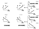
図2は温度(temp)と制御電圧(V)の関係を示す図である。尚、本発明の制御電圧は図15に示すような構成の周波数温度補償回路61を制御するためのものであり、以下、同様である。図2(a)、(e)は従来技術による高温側制御電圧と低温側制御電圧であり、図2(b)、(f)は本発明のよる高温側制御電圧と低温側制御電圧である。即ち、高温側の制御電圧VHとして、高温1次電圧ゲイン調整回路82により図2(d)の1次電圧(温度上昇に対して、一次関数的な上昇を呈する電圧)を生成し、高温高次電圧ゲイン調整回路83により図2(c)の高次電圧(温度上昇に対して指数関数的な上昇を呈する電圧)を生成し、これらの電圧を合成回路86により合成して図2(b)に示すごとく、VHは温度が高温側で1次電圧に(i)のような高次電圧(温度上昇に対して一次関数+指数関数的な上昇を呈する電圧)となる。また、低温側の制御電圧VLとして、低温1次電圧ゲイン調整回路84により図2(h)の1次電圧(温度下降に対して一次関数的な上昇を呈する電圧)を生成し、低温高次電圧ゲイン調整回路85により図2(g)の高次電圧(温度下降に対して指数関数的な上昇を呈する電圧)を生成し、これらの電圧を合成回路87により合成して図2(f)に示すごとく、VLは温度が低温側で1次電圧に(j)のような高次電圧(温度下降に対して一次関数+指数関数的な上昇を呈する関数)が合成されることになる。
FIG. 2 is a diagram showing the relationship between temperature (temp) and control voltage (V). The control voltage of the present invention is for controlling the frequency
図3はVH、VLの発生源として図1の温度補償電圧発生回路110を備えた図15(a)に示す温度補償型水晶発振器の温度特性を説明した図である。同図(a)に示す実線13は水晶振動子Xの周波数温度特性を示し、破線12は温度補償電圧発生回路110による周波数制御の特性を表す。この図から明らかな通り、水晶振動子Xの周波数温度特性の曲線部分を厳密に温度補償するに際してMOSバラクタの容量−一次電圧特性に基づく周波数制御量では周波数制御量に不足分が生じてしまうところを温度補償電圧発生回路110では、上述した高次電圧を利用して補償電圧の可変量を制御することによりその不足分を補うことができたので同図(a)に示すように水晶振動子Xの周波数温度特性13を相殺するに十分な周波数制御特性12が得られ、シミュレーションによる結果によれば、温度補償後の温度特性の精度は±0.5ppm範囲内となり、周波数安定度が高いTCXOが得られた。
尚、図1に示す周波数温度補償回路の場合では、図2(b)、(f)に示すように全温度範囲に於いて高温側の制御電圧VHと低温側の制御電圧VLが可変するものである為、例えば25℃以下の低温側の温度範囲に於いても、高温側MOSバラクタMHの可変容量特性が電圧変化に対して僅かに感度特性を有することで高温側の制御電圧VHの電圧の変化による影響が僅かながら生じてしまうが、当該高温側の制御電圧VHの可変により生じた周波数変動を加味して低温高次電圧ゲイン調整回路を設定すれば水晶振動子X以外の影響による周波数温度特性に対しても低温側の制御電圧VLによる周波数制御によって補償することができる。
即ち、高温側の制御電圧VHによる周波数制御を必要とする温度範囲が常温以上であり、図2(b)に示すように常温時の高温側の制御電圧VHの値がV1’=V1+Vrefである場合、図3(c)に示す高温側補償用のMOSバラクタMHの電圧―容量特性が電圧V1以下の範囲に於いて一定値である理想的なものであれば、常温以下の温度範囲に於いて高温側の制御電圧VHが変動するようなものであっても、MOSバラクタMHの容量は電圧V1以下の電圧範囲(電圧V1以下となる温度範囲)に於いて変化しないので低温時に於ける高温側の温度補償電圧VHの可変による影響は無いが、実際のMOSバラクタの電圧―容量特性では、電圧V1の近辺に於いても僅かながらの容量変化特性(図3(c)に示すΔc)をもつので低温時に於いても高温側の制御電圧VHの電圧変化による周波数の可変が僅かに起こる。
従って、この場合、低温時であれば水晶振動子Xの周波数温度特性以外に、高温側の制御電圧VHの可変により生じた周波数変動をも補償することを加味して低温高次電圧ゲイン調整回路を設定し、また、高温時に於いては低温側の制御電圧VLの可変により生じた周波数変動を補償することを加味して高温高次電圧ゲイン調整回路を設定することによりTCXOの周波数温度特性を高安定なものとすることができる。
Figure 3 is a diagram illustrating VH, the temperature characteristic of the temperature compensated crystal oscillator shown in FIG. 15 (a) having a temperature compensation
In the case of the frequency temperature compensation circuit shown in FIG. 1, the control voltage VH on the high temperature side and the control voltage VL on the low temperature side are variable in the entire temperature range as shown in FIGS. 2 (b) and 2 (f). Therefore, even in the low temperature range of 25 ° C. or less, for example, the variable capacitance characteristic of the high temperature side MOS varactor MH has a slight sensitivity characteristic to the voltage change, so that the voltage of the high temperature side control voltage VH is However, if the low-temperature high-order voltage gain adjustment circuit is set in consideration of the frequency fluctuation caused by the change in the control voltage VH on the high temperature side, the frequency due to the influence other than the crystal resonator X may occur. The temperature characteristic can also be compensated by frequency control using the control voltage VL on the low temperature side.
That is, the temperature range requiring frequency control by the control voltage VH on the high temperature side is equal to or higher than normal temperature, and the value of the control voltage VH on the high temperature side at normal temperature is V1 ′ = V1 + Vref as shown in FIG. In this case, if the voltage-capacitance characteristic of the high-temperature side compensation MOS varactor MH shown in FIG. Even if the control voltage VH on the high temperature side fluctuates, the capacitance of the MOS varactor MH does not change in the voltage range below the voltage V1 (the temperature range below the voltage V1). Although there is no influence due to the variation of the temperature compensation voltage VH on the side, in the actual voltage-capacitance characteristics of the MOS varactor, a slight capacity change characteristic (Δc shown in FIG. 3C) is present in the vicinity of the voltage V1. Because it has low temperature Also variable frequency by the voltage change of the control voltage VH of the high-temperature side at the place slightly.
Therefore, in this case, in the case of low temperature, in addition to the frequency temperature characteristics of the crystal unit X, the low temperature high-order voltage gain adjustment circuit is also taken into account to compensate for the frequency fluctuation caused by the variation of the control voltage VH on the high temperature side. The frequency temperature characteristics of the TCXO can be adjusted by setting a high-temperature high-order voltage gain adjustment circuit in consideration of compensating for frequency fluctuations caused by variable control voltage VL on the low temperature side at high temperatures. It can be highly stable.
図4(A)は本発明の他の実施例の周波数温度補償回路の機能ブロックであり図4(k)(m)は図4(A)に示す温度補償電圧発生回路100の合成回路6、7の出力特性として温度(temp)と制御電圧(V)の関係を示す図である。図4(b)、(f)は図1に示した合成回路86、87の出力特性を示すものであり、図4(k)は高温クリップ電圧8とダイオード10により常温付近から低温側をクリップした制御電圧の特性を示し、図4(m)は低温クリップ電圧9とダイオード11により常温付近から高温側をクリップした制御電圧の特性を示す図である。
図4(A)は本発明の第2の実施形態に係る温度補償型圧電発振器へ供給する補償電圧を発生する温度補償電圧発生回路の変形機能ブロック図である。この温度補償電圧発生回路100は、周囲温度によりパラメータが変化する温度センサ(温度検出部)1と、温度に対して直線的に変化する電圧を生成する高温1次電圧ゲイン調整回路(高温1次電圧生成手段)2と、この高温1次電圧ゲイン調整回路2により生成された電圧の高温側の温度に対して高次の次数を持つ電圧を生成する高温高次電圧ゲイン調整回路(高温高次電圧生成手段)3と、高温1次電圧ゲイン調整回路(高温電圧合成手段)6と、合成回路6の出力を所定のレベルでクリップする高温クリップ電圧(発生回路)8と、ダイオード10と、温度に対して直線的に変化する電圧を生成する低温1次電圧ゲイン調整回路(低温1次電圧生成手段)4と、この低温1次電圧ゲイン調整回路4により生成された電圧の低温側の温度に対して高次の次数を持つ電圧を生成する低温高次電圧ゲイン調整回路(低温高次電圧生成手段)5と、低温1次電圧ゲイン調整回路4及び低温高次電圧ゲイン調整回路5により出力される電圧を合成する合成回路(低温電圧合成手段)7と、合成回路7の出力を所定のレベルでクリップする低温クリップ電圧(発生回路)9と、ダイオード11と、を備えて構成される。
4A is a functional block of a frequency temperature compensation circuit according to another embodiment of the present invention, and FIGS. 4K and 4M show the synthesis circuit 6 of the temperature compensation
FIG. 4A is a modified functional block diagram of a temperature compensated voltage generation circuit for generating a compensation voltage to be supplied to the temperature compensated piezoelectric oscillator according to the second embodiment of the present invention. This temperature compensation
次に図4(A)に示す温度補償電圧発生回路100の動作について説明する。
図4(A)に示す温度補償電圧発生回路100に於ける高温1次電圧ゲイン調整回路2は、温度センサ1の温度情報を受けて図2(d)に示す1次関数電圧を出力し、また高温高次電圧ゲイン調整回路3は、温度センサ1の温度情報を受けて図2(c)に示す高温用高次関数電圧を出力する。
更に、合成回路6は、高温1次電圧ゲイン調整回路2の出力電圧と高温高次電圧ゲイン調整回路3の出力電圧を合成し、図4(b)に示す出力電圧VH’を出力する。
このとき出力電圧VH’は、常温にて電圧値がV1’であり、常温以下では温度の低下に伴い1次関数的に電圧値が低下し、また、常温以上では、温度の上昇に伴い指数関数的に上昇する部分を有する変化特性を呈するものである。
そして高温クリップ電圧(発生回路)8の出力電圧の値をV1’の値に設定することにより、合成回路6の出力電圧の値がV1’より低い状態(常温より低温の条件)に於いては、ダイオード10の端子間が順バイアスであるから高温クリップ電圧(発生回路)8の出力電圧の値V1’が高温側の制御電圧VHの値となる。
従って、高温側の制御電圧VHの値は、図4(k)に示すように常温以下の温度範囲に於いてはV1’であり、常温以上の温度範囲では、常温から所望の温度まで1次関数的に上昇し、且つ、所望の温度から更に高温にかけて指数関数的な電圧上昇特性を呈するものとなる。
Next, the operation of the temperature compensated
The high temperature primary voltage
Further, the synthesis circuit 6 synthesizes the output voltage of the high temperature primary voltage
At this time, the output voltage VH ′ has a voltage value of V1 ′ at room temperature, the voltage value decreases linearly with a decrease in temperature below room temperature, and an index with an increase in temperature above room temperature. It exhibits a change characteristic having a functionally rising part.
Then, by setting the value of the output voltage of the high temperature clip voltage (generation circuit) 8 to the value of V1 ′, in the state where the value of the output voltage of the synthesis circuit 6 is lower than V1 ′ (conditions lower than normal temperature). Since the
Therefore, the value of the control voltage VH on the high temperature side is V1 ′ in the temperature range below room temperature, as shown in FIG. 4 (k), and in the temperature range above room temperature, the primary voltage from room temperature to the desired temperature. It rises functionally and exhibits an exponential voltage rise characteristic from a desired temperature to a higher temperature.
一方、図4(A)に示す温度補償電圧発生回路100に於ける低温1次電圧ゲイン調整回路4は、温度センサ1の温度情報を受けて図2(h)に示す1次関数電圧を出力し、また低温高次電圧ゲイン調整回路5は、温度センサ1の温度情報を受けて図2(g)に示す低温用高次関数電圧を出力する。
更に、合成回路7は、低温1次電圧ゲイン調整回路4の出力電圧と低温高次電圧ゲイン調整回路5の出力電圧を合成し、図4(f)に示す出力電圧VL’を出力する。
このとき出力電圧VL’は、常温にて電圧値がV2’であり、常温以上では温度の上昇に伴い1次関数的に電圧値が低下しまた、常温以下では、温度の低下に伴い指数関数的に上昇する部分を有する変化特性を示すものである。
そして低温クリップ電圧(発生回路)9の出力電圧の値をV2’の値に設定することにより、合成回路7の出力電圧の値がV2’より高い状態(常温より高温の条件)に於いては、ダイオード11の端子間が順バイアスであるから低温クリップ電圧(発生回路)9の出力電圧の値V2’が高温側の制御電圧VLの値となる。
従って、低温側の制御電圧VLの値は、図4(m)に示すように常温以上の温度範囲に於いてはV2’であり、常温以下の温度範囲では、常温から所望の温度まで1次関数的に上昇し、且つ、所望の温度から更に低温にかけて指数関数的な電圧上昇特性を呈するものとなる。
これは上述したように例えば低温状態ではMOSバラクタMHによる温度補償を必要としないので、MOSバラクタMHの端子間電圧V1=VH−Vrefを図4(B)に示すようにMOSバラクタの電圧−容量特性が安定したポイントになるよう設定するが、この電圧−容量特性が安定したポイントであっても実際はわずかな電圧感度特性を持っている。
そこで、図1に示す実施例では、このようなMOSバラクタMHの好まざる電圧感度特性による周波数変動と、低温側の温度補償機能にて対応したが、図4(A)に示す実施例では、高温部の制御電圧VHを常温以下で一定値にすることで、低温における高温部の制御電圧の影響度を減少させることができるので、低温時では低温側の温度制御に調整工程等を、また高温時で有れば高温側の温度制御における調整工程等を簡略化できる。
On the other hand, the low temperature primary voltage gain adjustment circuit 4 in the temperature compensated
Further, the synthesis circuit 7 synthesizes the output voltage of the low temperature primary voltage gain adjustment circuit 4 and the output voltage of the low temperature high order voltage gain adjustment circuit 5 and outputs the output voltage VL ′ shown in FIG.
At this time, the output voltage VL ′ has a voltage value of V2 ′ at room temperature, the voltage value decreases linearly as the temperature rises above room temperature, and an exponential function as the temperature falls below room temperature. The change characteristic having the part which rises automatically.
Then, by setting the value of the output voltage of the low temperature clip voltage (generation circuit) 9 to the value of V2 ′, in the state where the value of the output voltage of the synthesis circuit 7 is higher than V2 ′ (conditions higher than normal temperature). Since the diode 11 is forward biased, the output voltage value V2 ′ of the low temperature clip voltage (generation circuit) 9 becomes the high temperature side control voltage VL.
Therefore, the value of the control voltage VL on the low temperature side is V2 ′ in the temperature range above room temperature as shown in FIG. 4 (m), and the primary from the room temperature to the desired temperature in the temperature range below room temperature. The voltage rises functionally, and exhibits an exponential voltage rise characteristic from a desired temperature to a lower temperature.
As described above, for example, since temperature compensation by the MOS varactor MH is not required in a low temperature state, the inter-terminal voltage V1 = VH−Vref of the MOS varactor MH is set to the voltage-capacitance of the MOS varactor as shown in FIG. Although the characteristic is set to be a stable point, even if this voltage-capacitance characteristic is a stable point, it actually has a slight voltage sensitivity characteristic.
Therefore, in the embodiment shown in FIG. 1, the frequency variation due to the undesirable voltage sensitivity characteristic of the MOS varactor MH and the temperature compensation function on the low temperature side are dealt with. However, in the embodiment shown in FIG. By setting the control voltage VH of the high temperature part to a constant value below room temperature, the influence of the control voltage of the high temperature part at low temperatures can be reduced. If the temperature is high, the adjustment process and the like in the temperature control on the high temperature side can be simplified.
図5(d)は図4(A)に示す温度補償電圧発生回路100を備えたTCXOの補償特性をコンピュータシミュレーションした結果を表す図であり、図5(b)は、従来の温度補償回路を備えたTCXOの周波数温度特性をコンピュータシミュレーションした結果である。この図から明らかなように、図5(b)の従来の温度補償回路によるものでは、−30℃〜+85℃の範囲で±2ppm内で変動するのに対して、本発明では図5(d)のように同温度範囲内において、±0.5ppm内に周波数偏差量が収まっており、高い周波数安定度が得られることがわかる。
尚、図5(a)、(c)は、温度補償すべき水晶振動子Xの周波数温度特性である。
FIG. 5 (d) is a diagram showing the result of computer simulation of the compensation characteristics of the TCXO having the temperature compensation
5A and 5C show the frequency temperature characteristics of the crystal unit X to be temperature compensated.
図6は本発明の第3の実施形態に係る温度補償型圧電発振器の一部を構成する温度補償電圧発生回路の機能ブロック図である。この周波数温度補償回路200は、周囲温度の変化に対応した電気的信号を出力する温度センサ(温度検出部)21と、温度センサ21の温度検知情報に基づき温度に対して比例関係となるように直線的に変化する電圧を生成する第1の高温1次電圧ゲイン調整回路(第1の高温1次電圧生成手段)24と、温度センサ21の温度検知情報に基づき温度上昇に対して比例関係となるように直線的に変化する電圧を生成する第2の高温1次電圧ゲイン調整回路(第2の高温1次電圧生成手段)23と、第2の高温1次電圧ゲイン調整回路23の所定の温度以下の範囲の電圧をダイオード28介してクリップする第2の高温電圧ゲインクリップ電圧(第2の高温1次電圧生成手段)22と、第1の高温1次電圧ゲイン調整回路24の出力電圧を第2の高温1次電圧生成手段22により制御された第2の高温1次電圧ゲイン調整回路23の出力電圧を合成する高温合成回路(高温電圧合成手段)31と、所望の温度以下の範囲にて高温合成回路31の出力をダイオード34を介して所定のレベルでクリップする高温クリップ電圧発生部30と、温度上昇に対して反比例関係となるように直線的に変化する電圧を生成する第1の低温1次電圧ゲイン調整回路(第1の低温1次電圧生成手段)25と、温度上昇に対して反比例関係となるように直線的に変化する電圧を生成する第2の低温1次電圧ゲイン調整回路(第2の低温1次電圧生成手段)26と、第2の低温1次電圧ゲイン調整回路26の所定の温度以上の範囲の電圧をダイオード29を介してクリップする第2の低温電圧ゲインクリップ電圧(第2の低温1次電圧生成手段)27と、第1の低温1次電圧ゲイン調整回路25の出力電圧と第2の低温1次電圧生成手段27により制御された第2の低温1次電圧ゲイン調整回路26の出力電圧とを合成する低温合成回路(低温電圧合成手段)32と、ダイオード35を介して低温合成回路32の出力を所定のレベルでクリップする低温クリップ電圧33と、を備えた構成である。
FIG. 6 is a functional block diagram of a temperature compensated voltage generating circuit constituting a part of the temperature compensated piezoelectric oscillator according to the third embodiment of the present invention. The frequency
図7は図6の機能ブロック図の第1高温1次電圧ゲイン調整回路24の出力電圧Aと、第2の高温1次電圧生成手段22により制御された第2の高温1次電圧ゲイン調整回路23の出力電圧Bと、高温合成回路31の出力電圧vhと、高温クリップ電圧発生部30により制御された高温合成回路31の出力電圧VHの各温度変化に対する電圧特性波形を示す図である。図7(a)の電圧Aは、上述した通り、温度上昇に対して比例関係となるように直線的に増加する電圧である。出力電圧Bは、第2の高温1次電圧ゲイン調整回路23からの全使用温度にわたって1次関数の上昇特性を呈する出力電圧を、第2の高温電圧ゲインクリップ電圧22とダイオード28によりTA℃(TA>25)以下の範囲において、第2の高温1次電圧生成手段22の出力電圧値にクリップした電圧特性である。図7(b)に示す出力電圧vhは図7(a)に示す出力電圧AとBを合成した電力特性であるからTA℃までは出力電圧Aの1次関数特性と電圧Bの1次関数特性との和の電圧特性であり、TA℃以下では、電圧Aの1次関数特性と電圧Bの0次関数特性との和の電圧特性である。図7(c)に示す電圧VHは電圧vhの、25℃以下の範囲における電圧を高温クリップ電圧発生部30の出力電圧値にクリップしたものである。尚、低温部は、第2の低温1次電圧生成手段27によるクリップ制御25℃未満の温度点(TB)以下の範囲であり、電圧Vlは図7(d)に示すような電圧VLは図7(e)に示すような電圧特性を呈するので説明を省略する。
図9(a)は図6に示す温度補償電圧発生回路200を備えたTCXOの周波数温度特性を示す図である。実線41は水晶振動子Xの周波数温度特性を示し、破線42は温度補償電圧発生回路200とMOSバラクタによる周波数可変特性を示す。この図から明らかな通り、温度補償電圧発生回路200は出力電圧特性を複数の温度範囲に区切り調整出来るので、水晶振動子Xの周波数温度特性を補償するための破線42に示す周波数可変特性を効率的に調整することが可能であり、この結果、温度補償後の温度特性の精度を±0.5ppm以内に安定させることができる。
尚、図9(b)は本発明の第2の実施形態による温度補償電圧発生回路200を備えたTCXOの補償特性のコンピュータシミュレーションの結果を表す図であり、図16(b)は従来の温度補償電圧により周波数温度補正したTCXOの周波数温度特性のコンピュータシミュレーションの結果を示す図である。この図から明らかなように、図16(b)の温度補償結果は、±2ppm内で変動するのに対して、本発明では図9(b)のように周波数偏差が±0.5ppm内に収まっており改善されていることがわかる。
7 shows the output voltage A of the first high temperature primary voltage
FIG. 9A is a diagram showing frequency temperature characteristics of the TCXO including the temperature compensated
FIG. 9B is a diagram showing the result of computer simulation of the compensation characteristics of the TCXO provided with the temperature compensation
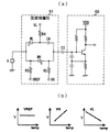
図11は本発明の第4の実施形態に係る温度補償型圧電発振器へ供給する制御電圧を発生するための温度補償電圧発生回路の機能ブロック図である。この温度補償電圧発生回路300は、周囲温度によりパラメータが変化することにより第1〜第3のセンサ電圧(A、B、C)を発生する温度センサ(温度検出部)51と、第2のセンサ電圧Bに基づいて温度上昇に対して比例関係となるような直線的に変化する電圧を生成する高温1次電圧ゲイン調整回路(高温1次電圧生成手段)54と、第1のセンサ電圧A及び第2のセンサ電圧Bを入力電圧として高温側における温度上昇に対して高次の次数を持つ(指数関数的な増加特性を呈する)電流を出力する高温高次電流発生回路(高温高次電流生成手段)52と、この出力電流を電圧に変換するゲイン調整回路(高温高次電圧生成手段)53と、高温1次電圧ゲイン調整回路54及びゲイン調整回路53の出力電圧を合成する高温合成回路(高温電圧合成手段)58と、高温合成回路58の出力電圧をダイオード61を介して、所定のレベルでクリップする高温クリップ電圧発生回路60と、第2のセンサ電圧Bに基づいて温度上昇に対して反比例関係となるような直線的に変化する電圧を生成する低温1次電圧ゲイン調整回路(低温1次電圧生成手段)55と、第3のセンサ電圧C及び第2のセンサ電圧Bを入力電圧として低温側における温度降下に対して高次の次数を持つ(指数関数的には増加特性を呈する)電流を出力する低温高次電流発生回路(低温高次電流生成手段)56と、この出力電流を電圧に変換するゲイン調整回路(低温高次電圧生成手段)57と、低温1次電圧ゲイン調整回路55及びゲイン調整回路57の出力電圧を合成する低温合成回路(低温電圧合成手段)59と、低温合成回路59の出力電圧を所定のレベルでダイオード63を介してクリップする低温クリップ電圧62と、を備えた構成である。
FIG. 11 is a functional block diagram of a temperature compensated voltage generation circuit for generating a control voltage to be supplied to a temperature compensated piezoelectric oscillator according to the fourth embodiment of the present invention. The temperature compensation
図12(a)は温度センサ51の温度に対するセンサ電圧A、B、Cの一例を示す図であり、図12(b)は各センサ電圧を発生する温度センサ(温度検出部)51の一例を示す回路図である。
温度センサ51は、センサ65としてのダイオード素子のアノード端を抵抗を介してオペアンプ(増幅器)66の反転入力端子に接続すると共に、当該ダイオード素子のカソード端を接地し、増幅器66の非反転入力端に基準電圧発生回路70の出力端を接続し、増幅器66の出力端と反転入力端とを帰還抵抗を介して接続すると共に、増幅回路66の出力端にダイオードD2のアノード端を接続し、ダイオードD2のカソード端を抵抗R1と抵抗R2とから成る直列回路を介して接地し、抵抗R1と抵抗R2との接続点を第1のセンサ電圧Aの出力端子Aとし、更に、増幅回路66の出力端に抵抗R3の一端を接続し、抵抗R3の他端と接地との間に2つのダイオードD3の順方向接続となるよう直列接続し、ダイオードD3と抵抗R3との接続点を第2のセンサ電圧Bの出力端子Bとし、更にまた、増幅器66の出力端に抵抗R4の一端を接続し、抵抗R4の他端に抵抗R5の一端を接続し、抵抗R5の他端と接地との間にダイオードD1を順方向接続し、抵抗R4と抵抗R5との接続点を第3のセンサ電圧Cの出力端子Cとするよう構成したものである。
12A is a diagram showing an example of sensor voltages A, B, and C with respect to the temperature of the
The
以下、温度センサ51の動作について説明する。
図12に示すセンサ65は、ダイオード素子であるから、センサ65に流れる電流が温度の上昇に伴い反比例関係となるような一次関数的に低下するよう動作するので、増幅器66の反転入力端には温度の上昇に伴い反比例関係となるような一次関数的に降下する電圧(少なくとも使用温度範囲内においては反転入力端に印加される電圧の絶対値は基準電圧値より小さい)が印加され、これに伴い増幅器66の出力端には温度の上昇に伴い比例関係となるような一次関数的に上昇する特性を呈する出力電圧が発生する。
そして、端子AにはダイオードD2と抵抗R1との直列回路と抵抗R2との分圧比に基づく電圧が発生し、端子Bには抵抗R3とダイオードD3との分圧比に基づく電圧が発生し、端子Cには抵抗5とダイオードD1との直列回路と抵抗4との分圧比に基づく電圧が発生する。
このときダイオードD2、D1については、温度上昇に伴い端子間電流が減少するよう動作する(ダイオードD2、D1の端子間のインピーダンスが大きくなる)というダイオード素子特有の温度特性を利用することにより、例えば温度変化に伴いダイオードD2と抵抗R1との直列回路と抵抗R2との抵抗比を温度変化に伴い変動させて、これに伴い増幅器66の出力電圧(センサ電圧A)の変動特性(変動率)を微調整しようとする為に備えたものであるが、抵抗の設定条件のみで調整可能な場合は、特に必要としなくても構わない。
一方、ダイオードD3については、温度上昇に伴い端子Bの電位を急激に降下させるよう例えば複数のダイオードを直列接続したものであるからそのダイオードの接続数を適切に設定することにより図12(a)に示す温度上昇に対して電圧変化率が負の傾きを有するセンサ電圧Bを出力端子Bから得ることができる。
そして、抵抗R1〜R5とダイオードD1〜D3及びその他回路素子を適切に設定すれば、図12(a)に示すように25℃未満の温度TLにてセンサ電圧BとCとの値が一致し、25℃より高温の温度THにてセンサ電圧AとBとの値が一致するようセンサ電圧A、B、Cを得ることができる。
Hereinafter, the operation of the
Since the sensor 65 shown in FIG. 12 is a diode element, the current flowing through the sensor 65 operates so as to decrease linearly so as to have an inversely proportional relationship as the temperature rises. A voltage that decreases linearly as the temperature rises is inversely proportional (at least within the operating temperature range, the absolute value of the voltage applied to the inverting input terminal is smaller than the reference voltage value). Along with this, an output voltage exhibiting a characteristic that increases linearly as the temperature rises is generated at the output terminal of the
A voltage based on the voltage dividing ratio between the resistor R2 and the series circuit of the diode D2 and the resistor R1 is generated at the terminal A, and a voltage based on the voltage dividing ratio between the resistor R3 and the diode D3 is generated at the terminal B. A voltage based on a voltage dividing ratio between the resistor 5 and the series circuit of the resistor 5 and the diode D1 and the resistor 4 is generated at C.
At this time, for the diodes D2 and D1, for example, by utilizing the temperature characteristics peculiar to the diode elements that operate so that the current between the terminals decreases as the temperature rises (the impedance between the terminals of the diodes D2 and D1 increases), for example, As the temperature changes, the resistance ratio between the series circuit of the diode D2 and the resistor R1 and the resistor R2 is changed according to the temperature change, and the change characteristic (rate of change) of the output voltage (sensor voltage A) of the
On the other hand, with respect to the diode D3, for example, a plurality of diodes are connected in series so that the potential at the terminal B drops rapidly as the temperature rises. The sensor voltage B having a negative slope with respect to the temperature rise shown in FIG.
If the resistors R1 to R5, the diodes D1 to D3, and other circuit elements are appropriately set, the values of the sensor voltages B and C match at a temperature TL of less than 25 ° C. as shown in FIG. The sensor voltages A, B, and C can be obtained so that the values of the sensor voltages A and B coincide at a temperature TH higher than 25 ° C.
図13は図11の高温高次電流発生回路52と低温高次電流発生回路56の回路図である。図12(a)を参照して説明する。高温高次電流発生回路52は、高温側ではA、Bのセンサ電圧を利用する。常温より低温部ではAよりBの電圧がはるかに大きいため抵抗R4側には電流が流れず、出力電流15thHはゼロである。温度が上昇するにつれてセンサA、B間の電位差はなくなり、R4側に電流が流れ始め、高温高次電流発生回路52の出力電流15thHが発生する。このとき発生する電流は常温付近を中心として高次の関数として近似できる。またセンサA、Bの電圧が同じになる温度THが温度補償範囲の高温側の端になるように調整を行う。低温側についても高温側と同様に動作し、センサB、Cの交点TLは温度補償範囲の低温側の端になるように調整を行う。ここで抵抗R1〜R4の抵抗値を変化させることで、温度に対する電流特性が変化し、見かけ上関数の次数が変化したように見えるので、この抵抗変化により高次次数を調整することができる。これにより、MOS型バラクタの特性を水晶振動子の特性に微調整することができる。
図14は高温高次電流の次数調整後の特性例を示す図である。この図から分かるとおりで抵抗R1〜R4の抵抗値を変化させることで、温度に対する電流特性71が変化し、見かけ上関数の次数が変化したように見える。この図では矢印の方向に変化すると見かけ上次数が小さくなることを表している。
FIG. 13 is a circuit diagram of the high-temperature high-order
FIG. 14 is a diagram illustrating a characteristic example after the order adjustment of the high-temperature high-order current. As can be seen from this figure, by changing the resistance values of the resistors R1 to R4, the current characteristic 71 with respect to temperature changes, and it appears that the order of the function has changed apparently. This figure shows that the order is apparently reduced when it changes in the direction of the arrow.
1 温度センサ、2 高温1次電圧ゲイン調整回路、3 高温高次電圧ゲイン調整回路、4 低温1次電圧ゲイン調整回路、5 低温高次電圧ゲイン調整回路、6 合成回路、7 合成回路、8 高温クリップ電圧、9 低温クリップ電圧、10 ダイオード、11 ダイオード、81 温度センサ(温度検出部)、82 高温1次電圧ゲイン調整回路(高温1次電圧生成手段)、83 高温高次電圧ゲイン調整回路(高温高次電圧生成手段)、84 低温1次電圧ゲイン調整回路(低温1次電圧生成手段)、85 低温高次電圧ゲイン調整回路(低温高次電圧生成手段)、86 合成回路(高温電圧合成手段)、87 合成回路(低温電圧合成手段)、100 温度補償電圧発生回路、110 温度補償電圧発生回路 1 temperature sensor, 2 high temperature primary voltage gain adjustment circuit, 3 high temperature high voltage gain adjustment circuit, 4 low temperature primary voltage gain adjustment circuit, 5 low temperature high voltage gain adjustment circuit, 6 synthesis circuit, 7 synthesis circuit, 8 high temperature Clip voltage, 9 Low temperature clip voltage, 10 Diode, 11 Diode, 81 Temperature sensor (temperature detector), 82 High temperature primary voltage gain adjustment circuit (high temperature primary voltage generation means), 83 High temperature high order voltage gain adjustment circuit (high temperature High-order voltage generation means), 84 Low-temperature primary voltage gain adjustment circuit (low-temperature primary voltage generation means), 85 Low-temperature high-order voltage gain adjustment circuit (low-temperature high-order voltage generation means), 86 Synthesis circuit (high-temperature voltage synthesis means) , 87 synthesis circuit (low temperature voltage synthesis means), 100 temperature compensation voltage generation circuit, 110 temperature compensation voltage generation circuit
Claims (7)
前記周波数温度補償回路は、周囲温度によりパラメータが変化する温度検出部により変化したパラメータに基づいて電圧を発生する温度補償用電圧発生部を備え、
前記温度補償用電圧発生部は、前記圧電素子の温度特性の常温を中心として低温側の温度特性を補償する電圧を発生する低温制御電圧発生部と、高温側の温度特性を補償する電圧を発生する高温制御電圧発生部とを備え、
前記低温制御電圧発生部は、温度に対して直線的に変化する電圧を生成する低温1次電圧生成手段と、該低温1次電圧生成手段により生成された電圧の低温側の温度に対して高次の次数を持つ電圧を生成する低温高次電圧生成手段と、前記低温1次電圧生成手段及び低温高次電圧生成手段により生成される電圧を合成する低温電圧合成手段とを備え、
前記温度補償用電圧発生部は、低温時には、前記高温制御電圧発生部の前記低温時における出力電圧の変化により生じる前記発振周波数の変動を補償するように、前記低温高次電圧生成手段を設定することを特徴とする温度補償型圧電発振器。 A piezoelectric device including an oscillation circuit that excites a piezoelectric element by passing a current, a fixed capacitance element for blocking DC, a frequency temperature compensation circuit that compensates for a change in oscillation frequency due to a temperature change, and a piezoelectric element that is excited at a predetermined frequency. A temperature-compensated piezoelectric oscillator having a vibrator,
The frequency temperature compensation circuit includes a temperature compensation voltage generator that generates a voltage based on a parameter changed by a temperature detector whose parameter changes according to an ambient temperature.
The temperature compensation voltage generator generates a voltage that compensates for the temperature characteristics on the low temperature side centered on the temperature characteristics of the piezoelectric element, and generates a voltage that compensates for the temperature characteristics on the high temperature side. A high-temperature control voltage generator that
The low-temperature control voltage generator includes a low-temperature primary voltage generator that generates a voltage that varies linearly with respect to the temperature, and a low-temperature temperature of the voltage generated by the low-temperature primary voltage generator. Low-temperature high-order voltage generation means for generating a voltage having the following order; and low-temperature voltage synthesis means for synthesizing voltages generated by the low-temperature primary voltage generation means and the low-temperature high-order voltage generation means,
The temperature compensation voltage generator sets the low-temperature high-order voltage generator to compensate for fluctuations in the oscillation frequency caused by changes in the output voltage at the low temperature of the high-temperature control voltage generator at low temperatures. A temperature compensated piezoelectric oscillator characterized by the above.
前記周波数温度補償回路は、周囲温度によりパラメータが変化する温度検出部により変化したパラメータに基づいて電圧を発生する温度補償用電圧発生部を備え、
前記温度補償用電圧発生部は、前記圧電素子の温度特性の常温を中心として低温側の温度特性を補償する電圧を発生する低温制御電圧発生部と、高温側の温度特性を補償する電圧を発生する高温制御電圧発生部とを備え、
前記高温制御電圧発生部は、温度に対して直線的に変化する電圧を生成する高温1次電圧生成手段と、該高温1次電圧生成手段により生成された電圧の高温側の温度に対して高次の次数を持つ電圧を生成する高温高次電圧生成手段と、前記高温1次電圧生成手段及び高温高次電圧生成手段により生成される電圧を合成する高温電圧合成手段とを備え、
前記温度補償用電圧発生部は、高温時には、前記低温制御電圧発生部の前記高温時における出力電圧の変化により生じる前記発振周波数の変動を補償するように、前記高温高次電圧生成手段を設定することを特徴とする温度補償型圧電発振器。 A piezoelectric device including an oscillation circuit that excites a piezoelectric element by passing a current, a fixed capacitance element for blocking DC, a frequency temperature compensation circuit that compensates for a change in oscillation frequency due to a temperature change, and a piezoelectric element that is excited at a predetermined frequency. A temperature-compensated piezoelectric oscillator having a vibrator,
The frequency temperature compensation circuit includes a temperature compensation voltage generator that generates a voltage based on a parameter changed by a temperature detector whose parameter changes according to an ambient temperature.
The temperature compensation voltage generator generates a voltage that compensates for the temperature characteristics on the low temperature side centered on the temperature characteristics of the piezoelectric element, and generates a voltage that compensates for the temperature characteristics on the high temperature side. A high-temperature control voltage generator that
The high-temperature control voltage generator includes a high-temperature primary voltage generator that generates a voltage that varies linearly with respect to the temperature, and a high-temperature side voltage that is generated by the high-temperature primary voltage generator. High-temperature high-order voltage generation means for generating a voltage having the following order; and high-temperature voltage synthesis means for synthesizing voltages generated by the high-temperature primary voltage generation means and the high-temperature high-order voltage generation means,
The temperature compensation voltage generator sets the high-temperature high-order voltage generator so as to compensate for fluctuations in the oscillation frequency caused by changes in the output voltage at the high temperature of the low-temperature control voltage generator at high temperatures. A temperature compensated piezoelectric oscillator characterized by the above.
前記周波数温度補償回路は、周囲温度によりパラメータが変化する温度検出部により変化したパラメータに基づいて電圧を発生する温度補償用電圧発生部を備え、
前記温度補償用電圧発生部は、前記圧電素子の温度特性の常温を中心として低温側の温度特性を補償する電圧を発生する低温制御電圧発生部と、高温側の温度特性を補償する電圧を発生する高温制御電圧発生部とを備え、
前記低温制御電圧発生部は、温度に対して直線的に変化する電圧を生成する低温1次電圧生成手段と、該低温1次電圧生成手段により生成された電圧の低温側の温度に対して高次の次数を持つ電圧を生成する低温高次電圧生成手段と、前記低温1次電圧生成手段及び低温高次電圧生成手段により生成される電圧を合成する低温電圧合成手段とを備え、
前記高温制御電圧発生部は、温度に対して直線的に変化する電圧を生成する高温1次電圧生成手段と、該高温1次電圧生成手段により生成された電圧の高温側の温度に対して高次の次数を持つ電圧を生成する高温高次電圧生成手段と、前記高温1次電圧生成手段及び高温高次電圧生成手段により生成される電圧を合成する高温電圧合成手段とを備え、
前記温度補償用電圧発生部は、低温時には、前記高温制御電圧発生部の前記低温時における出力電圧の変化により生じる前記発振周波数の変動を補償するように、前記低温高次電圧生成手段を設定し、高温時には、前記低温制御電圧発生部の前記高温時における出力電圧の変化により生じる前記発振周波数の変動を補償するように、前記高温高次電圧生成手段を設定することを特徴とする温度補償型圧電発振器。 A piezoelectric device including an oscillation circuit that excites a piezoelectric element by passing a current, a fixed capacitance element for blocking DC, a frequency temperature compensation circuit that compensates for a change in oscillation frequency due to a temperature change, and a piezoelectric element that is excited at a predetermined frequency. A temperature-compensated piezoelectric oscillator having a vibrator,
The frequency temperature compensation circuit includes a temperature compensation voltage generator that generates a voltage based on a parameter changed by a temperature detector whose parameter changes according to an ambient temperature.
The temperature compensation voltage generator generates a voltage that compensates for the temperature characteristics on the low temperature side centered on the temperature characteristics of the piezoelectric element, and generates a voltage that compensates for the temperature characteristics on the high temperature side. A high-temperature control voltage generator that
The low-temperature control voltage generator includes a low-temperature primary voltage generator that generates a voltage that varies linearly with respect to the temperature, and a low-temperature temperature of the voltage generated by the low-temperature primary voltage generator. Low-temperature high-order voltage generation means for generating a voltage having the following order; and low-temperature voltage synthesis means for synthesizing voltages generated by the low-temperature primary voltage generation means and the low-temperature high-order voltage generation means,
The high-temperature control voltage generator includes a high-temperature primary voltage generator that generates a voltage that varies linearly with respect to the temperature, and a high-temperature side voltage that is generated by the high-temperature primary voltage generator. High-temperature high-order voltage generation means for generating a voltage having the following order; and high-temperature voltage synthesis means for synthesizing voltages generated by the high-temperature primary voltage generation means and the high-temperature high-order voltage generation means,
The temperature compensation voltage generator sets the low-temperature high-order voltage generator to compensate for fluctuations in the oscillation frequency caused by a change in the output voltage at the low temperature of the high-temperature control voltage generator when the temperature is low. The temperature-compensating type is characterized in that the high-temperature high-order voltage generation means is set so as to compensate for fluctuations in the oscillation frequency caused by a change in the output voltage at the high temperature of the low-temperature control voltage generator at a high temperature. Piezoelectric oscillator.
前記周波数温度補償回路は、周囲温度によりパラメータが変化する温度検出部により変化したパラメータに基づいて電圧を発生する温度補償用電圧発生部を備え、
前記温度検出部は、低温から温度が上昇するに従って直線的に上昇する電圧を発生する第1のセンサ電圧発生回路と、低温から温度が上昇するに従って直線的に下降する電圧を発生する第2のセンサ電圧発生回路と、低温から温度が上昇するに従って直線的に上昇する電圧を発生する第3のセンサ電圧発生回路と、を備え、
前記温度補償用電圧発生部は、前記圧電素子の温度特性の常温を中心として低温側の温度特性を補償する電圧を発生する低温制御電圧発生部と、高温側の温度特性を補償する電圧を発生する高温制御電圧発生部とを備え、
前記低温制御電圧発生部は、前記第2のセンサ電圧に基づいて直線的に変化する電圧を生成する低温1次電圧生成手段と、前記第2のセンサ電圧及び前記第3のセンサ電圧に基づいて前記低温1次電圧生成手段により生成された電圧の低温側の温度に対して高次の次数を持つ電圧を生成する低温高次電圧生成手段と、前記低温1次電圧生成手段及び低温高次電圧生成手段から生成される電圧を合成する低温電圧合成手段とを備え、
前記高温制御電圧発生部は、前記第2のセンサ電圧に基づいて直線的に変化する電圧を生成する高温1次電圧生成手段と、前記第1のセンサ電圧及び前記第2のセンサ電圧に基づいて前記高温1次電圧生成手段により生成された電圧の高温側の温度に対して高次の次数を持つ電圧を生成する高温高次電圧生成手段と、前記高温1次電圧生成手段及び高温高次電圧生成手段から生成される電圧を合成する高温電圧合成手段とを備えたことを特徴とする温度補償型圧電発振器。 A piezoelectric device including an oscillation circuit that excites a piezoelectric element by passing a current, a fixed capacitance element for blocking DC, a frequency temperature compensation circuit that compensates for a change in oscillation frequency due to a temperature change, and a piezoelectric element that is excited at a predetermined frequency. A temperature-compensated piezoelectric oscillator having a vibrator,
The frequency temperature compensation circuit includes a temperature compensation voltage generator that generates a voltage based on a parameter changed by a temperature detector whose parameter changes according to an ambient temperature.
The temperature detection unit generates a first sensor voltage generation circuit that generates a voltage that increases linearly as the temperature increases from a low temperature, and a second sensor that generates a voltage that decreases linearly as the temperature increases from a low temperature. A sensor voltage generation circuit; and a third sensor voltage generation circuit that generates a voltage that increases linearly as the temperature rises from a low temperature,
The temperature compensation voltage generator generates a voltage that compensates for the temperature characteristics on the low temperature side centered on the temperature characteristics of the piezoelectric element, and generates a voltage that compensates for the temperature characteristics on the high temperature side. A high-temperature control voltage generator that
The low temperature control voltage generation unit is based on a low temperature primary voltage generation means for generating a voltage that changes linearly based on the second sensor voltage, and on the second sensor voltage and the third sensor voltage. Low-temperature high-order voltage generation means for generating a voltage having a higher order with respect to the temperature on the low-temperature side of the voltage generated by the low-temperature primary voltage generation means, the low-temperature primary voltage generation means, and the low-temperature high-order voltage Low temperature voltage synthesis means for synthesizing the voltage generated from the generation means,
The high temperature control voltage generation unit is based on high temperature primary voltage generation means for generating a voltage that varies linearly based on the second sensor voltage, and on the first sensor voltage and the second sensor voltage. High-temperature high-order voltage generating means for generating a voltage having a high-order with respect to the temperature on the high-temperature side of the voltage generated by the high-temperature primary voltage generating means, the high-temperature primary voltage generating means, and the high-temperature high-order voltage A temperature-compensated piezoelectric oscillator comprising: high-temperature voltage synthesis means for synthesizing voltages generated from the generation means.
Priority Applications (5)
| Application Number | Priority Date | Filing Date | Title |
|---|---|---|---|
| JP2005066395A JP4670406B2 (en) | 2005-03-09 | 2005-03-09 | Temperature compensated piezoelectric oscillator |
| US11/370,564 US7292117B2 (en) | 2005-03-09 | 2006-03-08 | Temperature-compensated piezoelectric oscillator |
| EP06004716A EP1701438A3 (en) | 2005-03-09 | 2006-03-08 | Temperature-compensated piezoelectric oscillator |
| KR1020060022284A KR100759641B1 (en) | 2005-03-09 | 2006-03-09 | Temperature-compensated piezoelectric oscillator |
| CNB2006100568975A CN100488027C (en) | 2005-03-09 | 2006-03-09 | Temperature-compensated piezoelectric oscillator |
Applications Claiming Priority (1)
| Application Number | Priority Date | Filing Date | Title |
|---|---|---|---|
| JP2005066395A JP4670406B2 (en) | 2005-03-09 | 2005-03-09 | Temperature compensated piezoelectric oscillator |
Publications (3)
| Publication Number | Publication Date |
|---|---|
| JP2006253974A JP2006253974A (en) | 2006-09-21 |
| JP2006253974A5 JP2006253974A5 (en) | 2008-07-31 |
| JP4670406B2 true JP4670406B2 (en) | 2011-04-13 |
Family
ID=36481271
Family Applications (1)
| Application Number | Title | Priority Date | Filing Date |
|---|---|---|---|
| JP2005066395A Active JP4670406B2 (en) | 2005-03-09 | 2005-03-09 | Temperature compensated piezoelectric oscillator |
Country Status (5)
| Country | Link |
|---|---|
| US (1) | US7292117B2 (en) |
| EP (1) | EP1701438A3 (en) |
| JP (1) | JP4670406B2 (en) |
| KR (1) | KR100759641B1 (en) |
| CN (1) | CN100488027C (en) |
Families Citing this family (16)
| Publication number | Priority date | Publication date | Assignee | Title |
|---|---|---|---|---|
| CN201422100Y (en) * | 2009-04-25 | 2010-03-10 | 鸿富锦精密工业(深圳)有限公司 | Crystal oscillating circuit and electronic device with crystal oscillating circuit |
| CN101996119A (en) * | 2009-08-13 | 2011-03-30 | 鸿富锦精密工业(深圳)有限公司 | Temperature automatic measurement system and measurement method |
| JP5839884B2 (en) * | 2011-08-11 | 2016-01-06 | 日本電波工業株式会社 | Temperature compensated crystal oscillator |
| JP5854769B2 (en) * | 2011-11-02 | 2016-02-09 | 京セラクリスタルデバイス株式会社 | Temperature compensated oscillator and temperature compensation method for temperature compensated oscillator |
| JP6123979B2 (en) * | 2012-05-23 | 2017-05-10 | セイコーエプソン株式会社 | Oscillator and electronic device |
| WO2014059181A2 (en) * | 2012-10-12 | 2014-04-17 | Accusilicon USA Inc. | Oscillator compensation circuits |
| US10120405B2 (en) * | 2014-04-04 | 2018-11-06 | National Instruments Corporation | Single-junction voltage reference |
| CN104320085B (en) * | 2014-11-18 | 2017-02-22 | 中国兵器工业集团第二一四研究所苏州研发中心 | Low-temperature-excursion CMOS oscillator circuit |
| CN104485891B (en) * | 2014-11-18 | 2017-05-03 | 中国兵器工业集团第二一四研究所苏州研发中心 | Low-temperature-drift CMOS (complementary metal oxide semiconductor) oscillator circuit |
| JP6798121B2 (en) | 2016-03-18 | 2020-12-09 | セイコーエプソン株式会社 | Oscillators, electronics and mobiles |
| JP7035604B2 (en) * | 2017-03-23 | 2022-03-15 | セイコーエプソン株式会社 | Temperature-compensated oscillators, electronic devices and mobiles |
| US11250827B2 (en) | 2018-03-30 | 2022-02-15 | Carrier Corporation | Temperature compensation for piezo sounder |
| WO2020067341A1 (en) * | 2018-09-28 | 2020-04-02 | 株式会社村田製作所 | Temperature compensation circuit and temperature compensation crystal oscillator |
| WO2020066672A1 (en) * | 2018-09-28 | 2020-04-02 | 株式会社村田製作所 | Temperature compensation circuit and temperature compensated crystal oscillator |
| WO2021009956A1 (en) * | 2019-07-17 | 2021-01-21 | 株式会社村田製作所 | Temperature compensation circuit and temperature compensated crystal oscillator |
| JP7232156B2 (en) * | 2019-09-04 | 2023-03-02 | 株式会社東芝 | oscillator |
Citations (3)
| Publication number | Priority date | Publication date | Assignee | Title |
|---|---|---|---|---|
| JPH11261336A (en) * | 1998-03-10 | 1999-09-24 | Toyo Commun Equip Co Ltd | Temperature compensation-type piezoelectric oscillator |
| JP2003133854A (en) * | 2001-10-29 | 2003-05-09 | Toyo Commun Equip Co Ltd | Voltage generator for compensating temperature and oscillator |
| JP2004343733A (en) * | 2003-04-25 | 2004-12-02 | Toyo Commun Equip Co Ltd | Temperature compensated oscillator |
Family Cites Families (11)
| Publication number | Priority date | Publication date | Assignee | Title |
|---|---|---|---|---|
| GB2233513A (en) * | 1989-06-09 | 1991-01-09 | Philips Electronic Associated | Oscillators |
| US5041799A (en) * | 1990-11-05 | 1991-08-20 | Motorola, Inc. | Temperature compensation circuit for a crystal oscillator |
| EP0998022A4 (en) * | 1997-07-11 | 2004-12-15 | Matsushita Electric Ind Co Ltd | Function generation circuit, crystal oscillation device, and method of adjusting the crystal oscillation device |
| JPH11220327A (en) * | 1997-10-31 | 1999-08-10 | Dynamics Corp Of America | Temperature compensation circuit for oscillator |
| JP2001267847A (en) * | 2000-03-17 | 2001-09-28 | Asahi Kasei Microsystems Kk | Temperature compensated crystal oscillator and method for compensating temperature or the oscillator |
| KR100376483B1 (en) * | 2000-10-20 | 2003-03-17 | 삼성전기주식회사 | Cubic function generation circuit |
| JP2003122420A (en) | 2001-10-11 | 2003-04-25 | Ricoh Elemex Corp | Production management system and program to be run by computer |
| AU2003261760A1 (en) * | 2002-08-28 | 2004-04-30 | Asahi Kasei Microsystems Co., Ltd. | DEVICE FOR GENERATING FUNCTION OF APPROXIMATE n-TH DEGREE AND TEMPERATURE COMPENSATION QUARTZ OSCILLATION CIRCUIT |
| JP2004336373A (en) * | 2003-05-07 | 2004-11-25 | Toyo Commun Equip Co Ltd | Temperature compensation piezoelectric oscillator |
| JP2005006030A (en) | 2003-06-11 | 2005-01-06 | Toyo Commun Equip Co Ltd | Temperature compensated piezoelectric oscillator |
| JP2005033329A (en) | 2003-07-08 | 2005-02-03 | Citizen Watch Co Ltd | Temperature compensated piezoelectric oscillator |
-
2005
- 2005-03-09 JP JP2005066395A patent/JP4670406B2/en active Active
-
2006
- 2006-03-08 EP EP06004716A patent/EP1701438A3/en not_active Withdrawn
- 2006-03-08 US US11/370,564 patent/US7292117B2/en active Active
- 2006-03-09 KR KR1020060022284A patent/KR100759641B1/en active IP Right Grant
- 2006-03-09 CN CNB2006100568975A patent/CN100488027C/en active Active
Patent Citations (3)
| Publication number | Priority date | Publication date | Assignee | Title |
|---|---|---|---|---|
| JPH11261336A (en) * | 1998-03-10 | 1999-09-24 | Toyo Commun Equip Co Ltd | Temperature compensation-type piezoelectric oscillator |
| JP2003133854A (en) * | 2001-10-29 | 2003-05-09 | Toyo Commun Equip Co Ltd | Voltage generator for compensating temperature and oscillator |
| JP2004343733A (en) * | 2003-04-25 | 2004-12-02 | Toyo Commun Equip Co Ltd | Temperature compensated oscillator |
Also Published As
| Publication number | Publication date |
|---|---|
| EP1701438A2 (en) | 2006-09-13 |
| KR100759641B1 (en) | 2007-09-17 |
| EP1701438A3 (en) | 2008-01-23 |
| KR20060098325A (en) | 2006-09-18 |
| JP2006253974A (en) | 2006-09-21 |
| US7292117B2 (en) | 2007-11-06 |
| US20060202772A1 (en) | 2006-09-14 |
| CN1832332A (en) | 2006-09-13 |
| CN100488027C (en) | 2009-05-13 |
Similar Documents
| Publication | Publication Date | Title |
|---|---|---|
| JP4670406B2 (en) | Temperature compensated piezoelectric oscillator | |
| JP5495356B2 (en) | Physical quantity sensor | |
| US7633350B2 (en) | Function generation circuit | |
| US7924109B2 (en) | MEMS oscillator | |
| US20100127787A1 (en) | Voltage control type temperature compensation piezoelectric oscillator | |
| JPH104318A (en) | Temperature compensation type crystal oscillator | |
| TW201308878A (en) | Temperature-compensated crystal oscillator | |
| US20100214035A1 (en) | Reference Frequency Control Circuit | |
| US8659361B2 (en) | Function generator circuit | |
| WO2015199068A1 (en) | Oscillation device | |
| WO2014025575A1 (en) | Method and apparatus to control the lc tank temperature null characteristic in a highly stable lc oscillator | |
| US20090128259A1 (en) | Automatic regulator of filter | |
| US10193557B2 (en) | Oscillation control apparatus and oscillation apparatus | |
| JP2008211757A (en) | Temperature compensated piezoelectric oscillator | |
| CN115118278A (en) | Voltage-controlled oscillator, phase-locked loop circuit, optical detection device and laser radar | |
| JP2002135051A (en) | Piezoelectric oscillator | |
| JP4428124B2 (en) | Temperature compensated oscillator | |
| JP2002026658A (en) | Quartz oscillator circuit | |
| JP4314988B2 (en) | Temperature compensated piezoelectric oscillator | |
| JP2006033092A (en) | Piezoelectric oscillator | |
| JP4311313B2 (en) | Piezoelectric oscillator | |
| JP2016082472A (en) | Oscillator and calibration method thereof | |
| JP2015056728A (en) | Oscillator | |
| JP2009124401A (en) | Oscillator | |
| JP2008136029A (en) | Approximate cubic function generation circuit and temperature compensation type crystal oscillator circuit |
Legal Events
| Date | Code | Title | Description |
|---|---|---|---|
| A521 | Request for written amendment filed |
Free format text: JAPANESE INTERMEDIATE CODE: A523 Effective date: 20080208 |
|
| A621 | Written request for application examination |
Free format text: JAPANESE INTERMEDIATE CODE: A621 Effective date: 20080208 |
|
| A521 | Request for written amendment filed |
Free format text: JAPANESE INTERMEDIATE CODE: A523 Effective date: 20080613 |
|
| A977 | Report on retrieval |
Free format text: JAPANESE INTERMEDIATE CODE: A971007 Effective date: 20100813 |
|
| A131 | Notification of reasons for refusal |
Free format text: JAPANESE INTERMEDIATE CODE: A131 Effective date: 20100824 |
|
| A521 | Request for written amendment filed |
Free format text: JAPANESE INTERMEDIATE CODE: A523 Effective date: 20101025 |
|
| TRDD | Decision of grant or rejection written | ||
| A01 | Written decision to grant a patent or to grant a registration (utility model) |
Free format text: JAPANESE INTERMEDIATE CODE: A01 Effective date: 20101221 |
|
| A01 | Written decision to grant a patent or to grant a registration (utility model) |
Free format text: JAPANESE INTERMEDIATE CODE: A01 |
|
| A61 | First payment of annual fees (during grant procedure) |
Free format text: JAPANESE INTERMEDIATE CODE: A61 Effective date: 20110103 |
|
| R150 | Certificate of patent or registration of utility model |
Free format text: JAPANESE INTERMEDIATE CODE: R150 Ref document number: 4670406 Country of ref document: JP Free format text: JAPANESE INTERMEDIATE CODE: R150 |
|
| FPAY | Renewal fee payment (event date is renewal date of database) |
Free format text: PAYMENT UNTIL: 20140128 Year of fee payment: 3 |
|
| FPAY | Renewal fee payment (event date is renewal date of database) |
Free format text: PAYMENT UNTIL: 20140128 Year of fee payment: 3 |
|
| S111 | Request for change of ownership or part of ownership |
Free format text: JAPANESE INTERMEDIATE CODE: R313111 |
|
| FPAY | Renewal fee payment (event date is renewal date of database) |
Free format text: PAYMENT UNTIL: 20140128 Year of fee payment: 3 |
|
| R371 | Transfer withdrawn |
Free format text: JAPANESE INTERMEDIATE CODE: R371 |
|
| FPAY | Renewal fee payment (event date is renewal date of database) |
Free format text: PAYMENT UNTIL: 20140128 Year of fee payment: 3 |
|
| S111 | Request for change of ownership or part of ownership |
Free format text: JAPANESE INTERMEDIATE CODE: R313111 |
|
| FPAY | Renewal fee payment (event date is renewal date of database) |
Free format text: PAYMENT UNTIL: 20140128 Year of fee payment: 3 |
|
| R350 | Written notification of registration of transfer |
Free format text: JAPANESE INTERMEDIATE CODE: R350 |
|
| S531 | Written request for registration of change of domicile |
Free format text: JAPANESE INTERMEDIATE CODE: R313531 |
|
| R350 | Written notification of registration of transfer |
Free format text: JAPANESE INTERMEDIATE CODE: R350 |