JP4669494B2 - Steel pipe pile construction method - Google Patents
Steel pipe pile construction method Download PDFInfo
- Publication number
- JP4669494B2 JP4669494B2 JP2007100269A JP2007100269A JP4669494B2 JP 4669494 B2 JP4669494 B2 JP 4669494B2 JP 2007100269 A JP2007100269 A JP 2007100269A JP 2007100269 A JP2007100269 A JP 2007100269A JP 4669494 B2 JP4669494 B2 JP 4669494B2
- Authority
- JP
- Japan
- Prior art keywords
- steel pipe
- pipe pile
- support layer
- soil
- pile
- Prior art date
- Legal status (The legal status is an assumption and is not a legal conclusion. Google has not performed a legal analysis and makes no representation as to the accuracy of the status listed.)
- Active
Links
Images


Description
本発明は、鋼管杭の施工方法に関し、詳しくは、先端部が開放した鋼管本体と、この鋼管本体の先端縁よりも下方に突出して固定された掘削用ビットとを有する鋼管杭を地盤に貫入する鋼管杭の施工方法に関する。 The present invention relates to a method for constructing a steel pipe pile, and more specifically, a steel pipe pile having a steel pipe main body with an open end and an excavation bit fixed to protrude downward from the front edge of the steel pipe main body is penetrated into the ground. The present invention relates to a method for constructing steel pipe piles.
従来、鋼管杭の施工方法としては、鋼管杭の先端部又は外周に翼(羽根)を有する鋼管杭を回転して翼のネジ作用により鋼管杭を地盤中に貫入する施工方法が知られている(例えば、特許文献1参照)。
また、地盤にセメントミルクなどの硬化剤を注入して鋼管を埋設する方法や、打撃力を用いて鋼管を埋設する方法なども知られている。
Conventionally, as a construction method of a steel pipe pile, a construction method is known in which a steel pipe pile having a blade (blade) on the tip or outer periphery of the steel pipe pile is rotated and the steel pipe pile is penetrated into the ground by the screw action of the blade. (For example, refer to Patent Document 1).
In addition, a method for embedding a steel pipe by injecting a hardener such as cement milk into the ground, a method for embedding a steel pipe using a striking force, and the like are also known.
しかしながら、前記特許文献1に記載の従来の鋼管杭の施工方法では、羽根によって地盤を掘削するので、貫入速度が羽根のピッチにより制限されるため、硬質でない地盤でも貫入速度が上がらないという問題がある。さらに、支持層のような硬質な地盤を掘削する場合には、羽根の面積分の地盤をせん断しながら掘削する必要があるため、施工負荷が非常に大きくなってしまい、鋼管杭の先端部を支持層に貫入できない場合も生じてしまう。
また、地盤にセメントミルクなどの硬化剤を注入して鋼管を埋設する方法では、セメントミルク等に用いるプラントなどの設備が必要であることに加え、セメントミルク等の材料費が余計に掛かってしまうという問題がある。また、打撃力を用いて鋼管を埋設する方法では、騒音・振動などが発生することから、鋼管を埋設できる場所が限られてしまう等の問題がある。
However, in the conventional steel pipe pile construction method described in
Moreover, in the method of embedding a steel pipe by injecting a hardener such as cement milk into the ground, in addition to the need for equipment such as a plant used for cement milk, etc., material costs such as cement milk will be added. There is a problem. In addition, in the method of burying a steel pipe using a striking force, noise, vibration, etc. are generated, and there is a problem that a place where the steel pipe can be embedded is limited.
本発明の目的は、硬質な地盤である支持層に達するまでの地盤では高い貫入速度を得ることができ、支持層では施工負荷の増加を抑えることができ、低い施工コストで、周辺への騒音や振動の問題が生じにくく、十分な支持力を確保できる鋼管杭の施工方法を提供することにある。 The object of the present invention is to obtain a high penetration speed in the ground up to the support layer, which is a hard ground, and to suppress an increase in construction load in the support layer, with low construction cost and noise to the surroundings. It is an object of the present invention to provide a method for constructing a steel pipe pile that is unlikely to cause problems of vibration and vibration and that can secure a sufficient supporting force.
本発明の請求項1に記載の鋼管杭の施工方法は、先端部が開放した鋼管本体と、この鋼管本体の先端縁よりも下方に突出して固定された掘削用ビットとを有する鋼管杭を地盤に貫入する鋼管杭の施工方法であって、前記鋼管本体の先端部が前記支持層に到達するまでは、排土手段を用いて前記鋼管本体内の少なくとも一部の土を排出し、かつ当該支持層よりも上方の土を所定高さだけ前記鋼管本体内部に残置し、前記鋼管本体の外径寸法の3倍程度以上の深さまで、当該鋼管本体の先端部を支持層に回転圧入する際に、削孔した支持層の土を排出せずに、当該支持層の土を前記鋼管本体内部に残置して当該鋼管本体の先端部を閉塞することを特徴とする。 According to a first aspect of the present invention, there is provided a steel pipe pile construction method comprising: a steel pipe pile having a steel pipe main body with an open end and an excavation bit fixed to protrude downward from a tip edge of the steel pipe main body; A method for constructing a steel pipe pile penetrating into the steel pipe, wherein at least part of the soil in the steel pipe body is discharged using a soil removing means until the tip of the steel pipe body reaches the support layer, and the upper soil predetermined height than the support layer is left on the inside of the steel tube body, until 3 times or more the depth of the outer diameter of the steel pipe body, when rotating press-fitting the distal end portion of the steel pipe body to a support layer In addition, without discharging the ground of the drilled support layer, the soil of the support layer is left inside the steel pipe body to close the tip of the steel pipe body .
ここで、鋼管本体の先端部が支持層に到達するまで鋼管杭を地盤に貫入する方法としては、鋼管杭を回転圧入する方法、鋼管杭に打撃や振動を加える方法など、適宜な貫入方法を採用してもよい。
このような鋼管杭の施工方法によれば、鋼管杭が開放した先端部を有する鋼管本体で形成され、鋼管杭の先端縁には下方に突出する掘削用ビットが固定されているだけなので、このような鋼管杭の鋼管本体の先端部が支持層に到達するまで、鋼管杭を地盤に貫入する際には、施工負荷を従来よりも低減させることができる。すなわち、従来の羽根を有する鋼管杭を貫入する場合のように、貫入速度が羽根のピッチにより制限されることがなく、地盤を掘削する部分が開放した鋼管本体の環状部分に取り付けられた掘削用ビットだけなので、従来に比べて鋼管杭の断面積が小さくなり、支持層に到達するまでの貫入速度を上げることができる。なお、掘削用ビットを鋼管本体の外周よりも外側に突出して固定する場合には、掘削用ビットの突出寸法が9mm〜12mmの範囲内であることが好ましい。
また、鋼管本体の先端部を支持層に回転圧入する際に、鋼管本体の先端部の掘削用ビットによって支持層を削孔するので、支持層に鋼管杭を円滑に貫入することができる。つまり、従来の羽根を有する鋼管杭を支持層に回転圧入する場合には、羽根の面積分の支持層をせん断しながら掘削する必要があるが、本発明では、前述のように地盤を掘削する部分が開放した鋼管本体の環状部分だけであるとともに、掘削用ビットを有しているので、施工負荷が大きくならず、鋼管杭の回転圧入負荷を低減することができる。
Here, as a method of penetrating the steel pipe pile into the ground until the tip of the steel pipe body reaches the support layer, an appropriate penetrating method such as a method of rotating and pressing the steel pipe pile or a method of hitting or vibrating the steel pipe pile is used. It may be adopted.
According to such a steel pipe pile construction method, the steel pipe pile is formed with a steel pipe body having an open tip, and a drilling bit protruding downward is fixed to the tip edge of the steel pipe pile. When the steel pipe pile penetrates the ground until the tip of the steel pipe body of the steel pipe pile reaches the support layer, the construction load can be reduced as compared with the conventional case. In other words, as in the case of penetrating a steel pipe pile having a conventional blade, the penetration speed is not limited by the pitch of the blade, and the excavation part attached to the annular part of the steel pipe main body where the ground excavating part is opened Since only the bit is used, the cross-sectional area of the steel pipe pile is smaller than in the conventional case, and the penetration speed until reaching the support layer can be increased. When the excavation bit is fixed so as to protrude outward from the outer periphery of the steel pipe main body, the projecting dimension of the excavation bit is preferably in the range of 9 mm to 12 mm.
In addition, when the distal end portion of the steel pipe main body is rotationally press-fitted into the support layer, the support layer is drilled by the excavating bit at the distal end portion of the steel pipe main body, so that the steel pipe pile can be smoothly penetrated into the support layer. In other words, when a steel pipe pile having a conventional blade is rotationally pressed into the support layer, it is necessary to excavate while shearing the support layer for the area of the blade, but in the present invention, the ground is excavated as described above. Since it is only the annular part of the steel pipe main body which the part opened, and it has a bit for excavation, the construction load does not increase, and the rotary press-fitting load of the steel pipe pile can be reduced.
また、鋼管本体の外径寸法(杭径寸法)の3倍程度以上の深さまで、鋼管本体の先端部を支持層に回転圧入し、当該鋼管本体の先端部を、回転圧入により削孔した支持層を形成する土等で閉塞するので、鋼管本体の先端部の閉塞度を十分に確保することができる。ここで言う土等とは、支持層を形成する砂質土、粘性土、岩、礫を含む支持層の地盤を形成するもの全てを示す。従って、鋼管杭の先端部分の見かけの断面積が大きくなるので、十分な支持力を確保することができる。この際、鋼管杭の先端部の掘削用ビットによって支持層を削孔するだけなので、鋼管杭の回転圧入によって支持層が大きく乱されることがなく、杭径寸法の3倍程度の鋼管杭の貫入寸法(根入れ深さ)であっても、十分な支持力を確保することができる。
また、従来のセメントミルクなどの硬化剤を注入する方法のように、セメントミルク用プラント等の設備が不要で、セメントミルク等の材料費も掛からないので、施工コストを下げることができる。また、従来の打撃力を用いて鋼管杭を支持層に埋設する方法のような騒音・振動などの発生を抑えることができるので、低騒音・低振動での施工が可能となる。
ここで、地盤の支持層とは、構造物を十分に支持できて、構造物の沈下の恐れのない地層であるが、構造物の設計者や行政機関が支持層を設定する際には、諸々の条件によって設定する支持層の深さ位置が変動する場合がある。本発明において、支持層への鋼管杭の貫入寸法を鋼管本体の杭径寸法の3倍程度以上としたのは、前述のような支持層の設定のバラツキを考慮したためで、3倍の前後1割程度(つまり2.7倍〜3.3倍)の誤差は、本発明の範囲に含まれる。
Moreover, the tip of the steel pipe body is rotationally press-fitted into the support layer to a depth of about 3 times the outer diameter dimension (pile diameter dimension) of the steel pipe body, and the tip part of the steel pipe body is supported by drilling through the rotational press-fit. Since it closes with the soil etc. which form a layer, the blockage degree of the front-end | tip part of a steel pipe main body can fully be ensured. The term “soil” as used herein refers to all that forms the ground of the support layer including sandy soil, viscous soil, rocks, and gravel that form the support layer. Therefore, since the apparent cross-sectional area of the tip portion of the steel pipe pile is increased, a sufficient supporting force can be ensured. At this time, since the support layer is only drilled by the excavation bit at the tip of the steel pipe pile, the support layer is not greatly disturbed by the rotational press-fitting of the steel pipe pile, and the steel pipe pile of about three times the pile diameter size Even if it is a penetration dimension (deep penetration depth), sufficient support force can be ensured.
In addition, unlike the conventional method of injecting a hardener such as cement milk, equipment such as a cement milk plant is not required, and material costs such as cement milk are not required. Therefore, the construction cost can be reduced. Moreover, since generation | occurrence | production of a noise, a vibration, etc. like the method of embedding a steel pipe pile in a support layer using the conventional impact force can be suppressed, construction with a low noise and a low vibration is attained.
Here, the ground support layer is a layer that can sufficiently support the structure and has no fear of subsidence of the structure, but when the structure designer or administrative organization sets the support layer, The depth position of the support layer to be set may vary depending on various conditions. In the present invention, the penetration dimension of the steel pipe pile into the support layer is set to be about three times or more the pile diameter dimension of the steel pipe main body in consideration of the variation in the setting of the support layer as described above. An error of about 20% (that is, 2.7 times to 3.3 times) is included in the scope of the present invention.
この際、本発明の鋼管杭の施工方法では、前記鋼管本体の先端部が前記支持層に到達するまでは、排土手段を用いて前記鋼管本体内の少なくとも一部の土を排出する。
ここで、鋼管本体内の少なくとも一部の土(管内土)の排土手段としては、例えば、鉄製の容器であるバケットを鋼管本体内にクレーンで降ろして、管内土をバケットに入れてクレーンで吊り上げることによって管内土を排出する方法(バケット法)でもよい。または、鋼管内に吸気管を挿入して、吸気管を通して管内土を吸い上げることによって排出する方法(エアーリフト法)でもよく、鋼管内にスクリューロッドを挿入して、スクリューの回転によって管内土を排出する方法(スクリューロッド法)でもよい。
このような構成によれば、鋼管杭が支持層に到達するまでは、排土手段を用いて鋼管本体内の少なくとも一部の管内土を排出するので、管内土が堆積することによる先端部の閉塞度を低減することができる。従って、支持層に到達するまで鋼管杭を貫入する際の施工負荷を低減でき、貫入速度を一層高めることができ、円滑に施工を実施できる。
At this time, in the construction method of the steel pipe pile according to the present invention, at least a part of the soil in the steel pipe body is discharged using the soil discharging means until the tip of the steel pipe body reaches the support layer .
Here, as a means for discharging at least a part of the soil (in-pipe soil) in the steel pipe body, for example, a bucket, which is an iron container, is lowered into the steel pipe body with a crane, and the in-pipe soil is put into the bucket with a crane. A method (bucket method) of discharging the pipe soil by lifting may be used. Alternatively, a method (air lift method) in which an intake pipe is inserted into the steel pipe and the soil in the pipe is sucked up through the intake pipe may be discharged (air lift method). A screw rod is inserted into the steel pipe and the soil in the pipe is discharged by rotating the screw. (Screw rod method) may be used.
According to such a configuration, until the steel pipe pile reaches the support layer, at least a part of the pipe soil in the steel pipe main body is discharged using the soil discharging means, so that the tip portion due to accumulation of the pipe soil is accumulated. The degree of occlusion can be reduced. Therefore, the construction load at the time of penetrating the steel pipe pile can be reduced until reaching the support layer, the penetration speed can be further increased, and the construction can be carried out smoothly.
また、本発明の鋼管杭の施工方法では、前記支持層は、一軸圧縮強度が5N/mm2以上の硬質地盤であることが好ましい。
このような構成によれば、支持層を一軸圧縮強度が5N/mm2以上の硬質地盤とすることによって、支持層に鋼管本体の先端部を回転圧入した際に、管内が硬質な土によって閉塞されるので、先端部の閉塞度をより大きくすることができ、より大きな支持力を確保することができる。
Moreover, in the construction method of the steel pipe pile of this invention, it is preferable that the said support layer is a hard ground whose uniaxial compressive strength is 5 N / mm < 2 > or more.
According to such a configuration, when the support layer is made of hard ground having a uniaxial compressive strength of 5 N / mm 2 or more, the inside of the pipe is blocked by hard soil when the tip of the steel pipe body is rotationally press-fitted into the support layer. As a result, the degree of occlusion at the tip can be increased, and a greater support force can be ensured.
以上のような本発明の鋼管杭の施工方法によれば、鋼管本体の先端部が支持層に到達するまで鋼管杭を地盤に貫入する際には、施工負荷を従来よりも低減させることができ、鋼管本体の先端部を支持層に回転圧入する際には、鋼管杭を円滑に支持層に貫入することができ、十分な支持力を確保することができるとともに、施工コストを下げることができ、低騒音・低振動での施工が可能となる。 According to the steel pipe pile construction method of the present invention as described above, when the steel pipe pile penetrates the ground until the tip of the steel pipe body reaches the support layer, the construction load can be reduced as compared with the conventional method. When the tip of the steel pipe body is rotationally press-fitted into the support layer, the steel pipe pile can be smoothly penetrated into the support layer, so that sufficient support force can be secured and the construction cost can be reduced. Construction with low noise and vibration is possible.
以下、本発明の実施形態を図面に基づいて説明する。
図1〜図5は、本発明の実施形態に係る鋼管杭1の施工方法を示す断面図である。
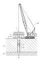
図1に示すように、本実施形態における鋼管杭1の施工方法は、全周旋回機2を使用して鋼管杭1を回転圧入させることによって、鋼管杭1を地盤に貫入するという方法である。
鋼管杭1は、両端が開口された鋼管本体1Aと、この鋼管本体1Aの下方の先端縁に固定された掘削用ビット1Bとを有する。掘削用ビット1Bは、鋼管本体1Aの外周に治具を介してロウ付けやボルト、あるいは鋼管本体1Aに直接溶接で取り付けられている。
掘削用ビット1Bは、鋼管本体1Aの先端縁よりも下方に突出するように形成され、また、鋼管本体1Aの外周面から外側への突出量が9mm〜12mmとなるように形成されている。なお、掘削用ビット1Bは、鋼管本体1Aの周面から内外の両方向へ突出して形成されていてもよい。これによって、地盤Gを乱す面積が大きくなり、鋼管本体1Aを貫入するのに必要な圧入力を小さくすることができる。ただし、内外への突出寸法は、周面摩擦に与える影響を少なくするために、9mm〜12mm以内とすることが望ましい。
Hereinafter, embodiments of the present invention will be described with reference to the drawings.
1-5 is sectional drawing which shows the construction method of the
As shown in FIG. 1, the construction method of the
The
The
次に、本実施形態の鋼管杭1の施工手順を説明する。
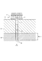
ここで、鋼管杭1を施工する地盤Gとしては、図1に示すように、地表側から砂質や粘土質を多く含んだ比較的軟弱な軟弱層G1と、軟弱層G1の下側に位置して礫や岩盤等で構成され硬質な支持層G2とから構成されているものとする。支持層G2としては、一般的に支持層として用いることが可能なN値30以上の地盤であればよい。なお、地盤Gの一軸圧縮強度が5N/mm2以上の軟岩等で構成された硬質な地層を支持層G2とすれば、後述する鋼管杭1の先端部の閉塞度が上がり、より高い支持力を確保する点で好ましい。
Next, the construction procedure of the
Here, as the ground G on which the
以下に、具体的な鋼管杭1の施工手順について図2〜図5に基づいて説明する。
施工手順としては先ず、図2に示すように、クレーンMを用いて鋼管杭1の先端部を全周旋回機2に取り付ける。全周旋回機2には、鋼管杭1を地盤に回転圧入した場合の鋼管杭1の反発力に対抗するために、複数の錘21が積載されている。ここで、本実施形態では、全周旋回機2を使用した施工方法を説明するが、支持層G2に到達するまでの中間地盤の硬度や、支持層G2の硬度・深さに応じて、全周旋回機2に限らず、3点式杭打ち機等を使用してもよい。そして、図1に示すように、全周旋回機2を使用して、鋼管杭1を回転圧入し、鋼管杭1先端の掘削用ビット1Bにより支持層G2までの軟弱層G1を掘削する。
Below, the concrete construction procedure of the
As a construction procedure, first, as shown in FIG. 2, the tip of the
次に、図3に示すように、施工負荷が上がった場合や施工負荷が上がることが予想される場合には、施工負荷の低減を図るため、排土手段であるバケット3で管内土を地上へ排出する。バケット3は、クレーンMで昇降され、吊り下げられた状態で開閉可能に構成されている。なお、排土する範囲は、支持層G2に到達する部分までの範囲で適宜設定することができる。例えば、全周旋回機2によって鋼管杭1を回転圧入中に、施工負荷が全周旋回機2の発生トルクまたは錘21を装着した状態での全周旋回機2の施工時に許容される圧入力を上回った場合には、全周旋回機2を一旦停止して、バケット3を用いて管内土を排出する。鋼管杭1の施工負荷が全周旋回機2の発生トルクまたは錘21の荷重よりも低くなるまで、管内土を排出した後、再び全周旋回機2を起動して鋼管杭1を回転圧入する。このようにして、鋼管本体1Aの先端部が支持層G2に到達するまで、鋼管杭1の回転圧入と管内土の排出を適宜繰り返す。
Next, as shown in FIG. 3, when the construction load increases or when the construction load is expected to rise, the
次に、鋼管本体1Aの先端部が支持層G2に到達した後は、管内土の排出は実施せず、鋼管杭1の回転圧入のみを続ける。鋼管本体1Aの上端が全周旋回機2の取り付け位置まで低下した後は、図4に示すように、鋼管杭1の上端に連結治具(ヤットコ等)4を連結して、鋼管杭1をさらに回転圧入する。このようにして、鋼管本体1Aの先端部を、鋼管本体1Aの外径寸法(杭径寸法)Dの3倍以上の深さまで支持層G2に回転圧入して、全周旋回機2を停止する。次に、鋼管杭1から全周旋回機2(または連結治具4)を切り離すとともに、鋼管杭1の杭頭部分の後処理を実施して、全周旋回機2を次の施工位置へ移動する。以上のようにして、鋼管杭1の施工作業が完了する。
図5には、鋼管杭1が支持層G2に杭径寸法Dの3倍以上貫入した状態が示されている。このように鋼管本体1Aの先端部が支持層G2に貫入され、かつ、掘削用ビット1Bによって削孔された支持層の硬質な土で閉塞されているので、鋼管杭1が確実に支持力を発揮することができる。
Next, after the tip of the steel pipe
FIG. 5 shows a state in which the
このような本実施形態によれば、以下のような効果がある。
(1)すなわち、先端が開口した鋼管杭1を用いて、杭径寸法Dの3倍以上の深さまで、鋼管本体1Aの先端部を支持層G2に回転圧入するので、削孔した支持層G2の土によって先端部の閉塞度が上昇し、閉塞された先端部分の見かけの断面積が大きくなることから、高い支持力を得ることができる。また、鋼管杭1に対して打撃等を行わず、支持層G2に回転圧入させるだけなので、低騒音・低振動とすることができる。
According to this embodiment, there are the following effects.
(1) That is, since the tip of the
(2)また、掘削用ビット1Bがろう付けされた鋼管本体1Aの環状部分だけで地盤Gを掘削し、支持層G2に支持力確保に必要な長さ、鋼管本体1Aの外径寸法の3倍以上、回転圧入することで、管内土が乱されず、鋼管杭1の先端部を確実に管内土によって閉塞することができ、これによって高い支持力を得ることができる。
(2) The ground G is excavated only by the annular portion of the steel pipe
(3)また、鋼管杭1を支持層G2に到達させるまで貫入する際に、地盤Gを掘削する部分が開放した鋼管本体1Aの環状部分だけであるとともに、掘削用ビット1Bを有しているので、施工負荷が大きくならず、鋼管杭1の回転圧入負荷を低減することができ、高い貫入速度が得られる。さらに、バケット3を用いて管内土を地上に上げるので、施工負荷をさらに低減させることができる。
(3) Further, when the
なお、本発明は、前記実施形態に限定されるものではなく、本発明の目的を達成できる他の構成等を含み、以下に示すような変形等も本発明に含まれる。
例えば、前記実施形態においては、排土手段としては、バケット3を使用する方法を説明をしたが、本発明では、例えば、スクリュー付きのロッドを使用する方法であってもよく、または、エアリフト装置を使用する方法であってもよい。エアリフト装置を使用する方法では、ロッドの内部を通して鋼管本体1A内部の管内土を吸い上げるエアリフト装置を使用してもよい。このエアリフト装置は、鋼管杭1の地上側の端部に設けられたエアポンプと、このエアポンプに連結された中空筒状のロッドと、ロッドで吸い上げた管内土を外部に排出する排出部とを有して構成されていてもよい。ここで、エアリフト装置の代わりに、鋼管杭1の内部に供給した水とともにロッドの内部を通して管内土を吸い上げる泥水リフト装置であってもよい。
In addition, this invention is not limited to the said embodiment, Including other structures etc. which can achieve the objective of this invention, the deformation | transformation etc. which are shown below are also contained in this invention.
For example, in the above-described embodiment, the method of using the
その他、本発明を実施するための最良の構成、方法などは、以上の記載で開示されているが、本発明は、これに限定されるものではない。すなわち、本発明は、主に特定の実施形態に関して特に図示され、かつ説明されているが、本発明の技術的思想および目的の範囲から逸脱することなく、以上述べた実施形態に対し、形状、材質、数量、その他の詳細な構成において、当業者が様々な変形を加えることができるものである。
従って、上記に開示した形状、材質などを限定した記載は、本発明の理解を容易にするために例示的に記載したものであり、本発明を限定するものではないから、それらの形状、材質などの限定の一部もしくは全部の限定を外した部材の名称での記載は、本発明に含まれるものである。
In addition, the best configuration, method and the like for carrying out the present invention have been disclosed in the above description, but the present invention is not limited to this. That is, the invention has been illustrated and described with particular reference to certain specific embodiments, but without departing from the spirit and scope of the invention, Various modifications can be made by those skilled in the art in terms of material, quantity, and other detailed configurations.
Therefore, the description limiting the shape, material, etc. disclosed above is an example for easy understanding of the present invention, and does not limit the present invention. The description by the name of the member which remove | excluded the limitation of one part or all of such restrictions is included in this invention.
次に、本発明の実施例を説明する。
以下の実施例は、地盤強度が一軸圧縮強度で5N/mm2から20N/mm2以下の範囲で実施した。
先ず、本発明の施工方法による施工負荷の試験結果について説明する。
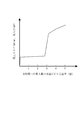
図6は、鋼管杭1を、支持層G2のような堅固な地盤に回転させながら圧入する試験を行った際の、地盤への貫入寸法の杭径寸法(鋼管本体1Aの外径寸法)に対する倍率と、施工負荷を示す施工トルクおよび圧入力を示している。この試験によれば、鋼管杭1の貫入寸法が杭径寸法の3倍程度で急上昇することが解る。
Next, examples of the present invention will be described.
In the following examples, the ground strength was uniaxial compressive strength in the range of 5 N / mm 2 to 20 N / mm 2 or less.
First, the test result of the construction load by the construction method of the present invention will be described.
FIG. 6 shows the pile diameter dimension (the outer diameter dimension of the steel pipe
次に、本発明の施工方法で施工された鋼管杭における杭先端の閉塞効果に関し、模型鋼管杭5を用いて模型試験した試験結果について説明する。
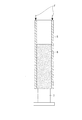
図7は、模型試験方法を説明する模式図である。図8は、前記模型試験方法における模型鋼管杭5の支持層G2への貫入寸法の杭径寸法に対する倍率と、押抜き抵抗との関係を示すグラフである。
本発明の鋼管杭の管内に取り込まれた土(管内土)による鋼管杭の先端部の閉塞度を調べるために、図7に示すような模型鋼管杭5を用いて、貫入寸法毎に管内土6を押し抜く試験を行った。
Next, the test results of the model test using the model
FIG. 7 is a schematic diagram for explaining a model test method. FIG. 8 is a graph showing the relationship between the magnification of the penetration dimension of the model
In order to examine the degree of blockage of the tip portion of the steel pipe pile by the soil (pipe soil) taken into the pipe of the steel pipe pile of the present invention, the model
本模型試験では、先端に掘削用ビット(図示を省く)を設けた模型鋼管杭5を使用する。まず、模型鋼管杭5を支持層G2の硬度と略同じ硬度を有する模型地盤に所定の貫入寸法分だけ回転圧入する。次に、模型鋼管杭5を模型地盤から引抜き、模型鋼管杭5の管内土6を受け台7に押し当てて、管内土6を押抜く方向に積荷重Fを加え、押抜き抵抗を測定する。そして、貫入寸法を模型鋼管杭5の杭径寸法の1倍から5倍程度の範囲で、適宜設定し、貫入寸法毎に模型鋼管杭5の回転圧入および押抜きを実施する。
本試験結果によると、模型鋼管杭5の貫入寸法と管内土6の高さ寸法(鋼管の長手方向に沿った寸法)は、略等しくなった。このことから、本実施形態の鋼管杭1の貫入寸法と管内土の高さ寸法とが略等しくなることが推定でき、管内土6の高さ寸法が地盤条件によって多少変化することを考慮しても、管内土6の高さ寸法は、鋼管杭1の貫入寸法の90%〜110%程度の範囲内とみなすことができる。
In this model test, a model
According to the test results, the penetration dimension of the model
さらに、本試験結果によると、図8に示すように、模型鋼管杭5の管内土6の押抜き抵抗は、模型鋼管杭5の貫入寸法が杭径寸法の3倍程度で急上昇し、図6に示す施工負荷と類似の傾向を示している。すなわち、支持層G2への貫入寸法が鋼管本体1Aの外径の3倍未満では先端閉塞による抵抗値が非常に小さいのに対し、支持層G2への貫入寸法が杭径寸法の3倍程度で極端に先端閉塞による抵抗値が上昇する。なお、貫入寸法が杭径寸法の3倍よりも大きい場合に、貫入寸法が杭径寸法の3倍未満での押抜き抵抗に対して10倍以上の押抜き抵抗が得られた。
以上の試験結果から、本発明の鋼管杭の施工方法によれば、鋼管杭の支持層G2への貫入寸法を杭径寸法の3倍程度以上としているので、管内土による鋼管杭の閉塞度が上昇し、必要な鋼管杭の支持力を確保することができることが判明した。
Further, according to the test results, as shown in FIG. 8, the punching resistance of the
From the above test results, according to the steel pipe pile construction method of the present invention, the penetration dimension of the steel pipe pile into the support layer G2 is set to be about three times the pile diameter dimension or more. Ascending, it was found that the necessary supporting capacity of steel pipe piles can be secured.
1…鋼管杭、1A…鋼管本体、1B…掘削用ビット、3…バケット(排土手段)、5…模型鋼管杭、6…管内土、7…受け台、D…杭径寸法(鋼管本体の外径寸法)、G…地盤、G2…支持層。
DESCRIPTION OF
Claims (2)
前記鋼管本体の先端部が前記支持層に到達するまでは、排土手段を用いて前記鋼管本体内の少なくとも一部の土を排出し、かつ当該支持層よりも上方の土を所定高さだけ前記鋼管本体内部に残置し、
前記鋼管本体の外径寸法の3倍程度以上の深さまで、当該鋼管本体の先端部を支持層に回転圧入する際に、削孔した支持層の土を排出せずに、当該支持層の土を前記鋼管本体内部に残置して当該鋼管本体の先端部を閉塞することを特徴とする鋼管杭の施工方法。 A steel pipe pile construction method for penetrating a steel pipe pile having a steel pipe main body with an open end and an excavating bit fixed to protrude downward from the tip edge of the steel pipe main body,
Until the tip of the steel pipe main body reaches the support layer, the soil removal means is used to discharge at least a part of the soil in the steel pipe main body , and the soil above the support layer is only a predetermined height. Leaving inside the steel pipe body,
Up to three times or more the depth of the outer diameter of the steel pipe body, when rotating press-fitting the distal end portion of the steel pipe body to the support layer, without discharging the soil supporting layer which is drilled, soil of the support layer Is left inside the steel pipe body, and the tip portion of the steel pipe body is closed.
前記支持層は、一軸圧縮強度が5N/mm2以上の硬質地盤であることを特徴とする鋼管杭の施工方法。 In the construction method of the steel pipe pile of Claim 1,
The steel pipe pile construction method, wherein the support layer is a hard ground having a uniaxial compressive strength of 5 N / mm 2 or more.
Priority Applications (1)
| Application Number | Priority Date | Filing Date | Title |
|---|---|---|---|
| JP2007100269A JP4669494B2 (en) | 2007-04-06 | 2007-04-06 | Steel pipe pile construction method |
Applications Claiming Priority (1)
| Application Number | Priority Date | Filing Date | Title |
|---|---|---|---|
| JP2007100269A JP4669494B2 (en) | 2007-04-06 | 2007-04-06 | Steel pipe pile construction method |
Publications (2)
| Publication Number | Publication Date |
|---|---|
| JP2008255695A JP2008255695A (en) | 2008-10-23 |
| JP4669494B2 true JP4669494B2 (en) | 2011-04-13 |
Family
ID=39979549
Family Applications (1)
| Application Number | Title | Priority Date | Filing Date |
|---|---|---|---|
| JP2007100269A Active JP4669494B2 (en) | 2007-04-06 | 2007-04-06 | Steel pipe pile construction method |
Country Status (1)
| Country | Link |
|---|---|
| JP (1) | JP4669494B2 (en) |
Cited By (1)
| Publication number | Priority date | Publication date | Assignee | Title |
|---|---|---|---|---|
| CN103306275A (en) * | 2013-06-19 | 2013-09-18 | 潘建杰 | Construction method for preformed end bearing pile in lava region |
Families Citing this family (3)
| Publication number | Priority date | Publication date | Assignee | Title |
|---|---|---|---|---|
| JP6623566B2 (en) * | 2015-06-03 | 2019-12-25 | ジャパンパイル株式会社 | Steel pipe pile burying method and steel pipe pile burying system |
| CN106968249A (en) * | 2017-03-29 | 2017-07-21 | 浙江理工大学 | The implementation method of piling after foundation-free |
| CN109723062A (en) * | 2019-01-18 | 2019-05-07 | 济南轨道交通集团有限公司 | Heave-load device hanging apparatus and hanging method based on proximity deep foundation pit construction environment |
Citations (3)
| Publication number | Priority date | Publication date | Assignee | Title |
|---|---|---|---|---|
| JPH04179728A (en) * | 1990-11-15 | 1992-06-26 | Kubota Corp | Immersion construction method of steel pipe pile |
| JP2002070469A (en) * | 2000-09-01 | 2002-03-08 | Nippon Sharyo Seizo Kaisha Ltd | Casing excavation method |
| JP2005002610A (en) * | 2003-06-10 | 2005-01-06 | Yokoyama Kiso Koji:Kk | Method for driving steel pipe pile, and screw type steel pipe |
-
2007
- 2007-04-06 JP JP2007100269A patent/JP4669494B2/en active Active
Patent Citations (3)
| Publication number | Priority date | Publication date | Assignee | Title |
|---|---|---|---|---|
| JPH04179728A (en) * | 1990-11-15 | 1992-06-26 | Kubota Corp | Immersion construction method of steel pipe pile |
| JP2002070469A (en) * | 2000-09-01 | 2002-03-08 | Nippon Sharyo Seizo Kaisha Ltd | Casing excavation method |
| JP2005002610A (en) * | 2003-06-10 | 2005-01-06 | Yokoyama Kiso Koji:Kk | Method for driving steel pipe pile, and screw type steel pipe |
Cited By (1)
| Publication number | Priority date | Publication date | Assignee | Title |
|---|---|---|---|---|
| CN103306275A (en) * | 2013-06-19 | 2013-09-18 | 潘建杰 | Construction method for preformed end bearing pile in lava region |
Also Published As
| Publication number | Publication date |
|---|---|
| JP2008255695A (en) | 2008-10-23 |
Similar Documents
| Publication | Publication Date | Title |
|---|---|---|
| JP4716134B2 (en) | Slope stabilization method | |
| JP5932124B1 (en) | Steel pipe pile construction method | |
| JP6932544B2 (en) | Construction method of support pile | |
| KR20050059183A (en) | Internal excavation method through pile, and foundation pile structure | |
| JP4669494B2 (en) | Steel pipe pile construction method | |
| JP4903620B2 (en) | Excavation device for pile construction and pile construction method | |
| JP2009256999A (en) | Pile extracting construction method for existing hollow pile | |
| JP6901928B2 (en) | Pile construction method | |
| KR100977979B1 (en) | Reinforcement device for marine pile using bucket foundation | |
| JP6696232B2 (en) | Construction method of rotary press-in steel pipe pile | |
| JP2007332559A (en) | Removal method for existing underground pile | |
| JP5177066B2 (en) | Steel pipe pile and its construction method | |
| JP4608327B2 (en) | The tip structure of a steel pipe pile used in the medium digging method. | |
| JP3760316B2 (en) | Intermediate striking pile and its construction method | |
| JP5698316B2 (en) | Construction method of foundation pile | |
| JP4874433B2 (en) | Steel pipe pile | |
| JP7215470B2 (en) | Steel pipe, steel pipe structure, method for constructing steel pipe structure | |
| KR100932952B1 (en) | Piles that have variable end | |
| JP5300163B1 (en) | Steel pile rooting method | |
| KR100859974B1 (en) | Pile and piling method thereof | |
| JP4114875B2 (en) | Root pile and ready-made pile | |
| JP5177064B2 (en) | Foundation pile and its construction method | |
| KR200318783Y1 (en) | steel pile with drilling blade | |
| JP2014109190A (en) | Foot protection method for steel pile | |
| JP7172978B2 (en) | Steel pipe, steel pipe structure, method for constructing steel pipe structure |
Legal Events
| Date | Code | Title | Description |
|---|---|---|---|
| A621 | Written request for application examination |
Free format text: JAPANESE INTERMEDIATE CODE: A621 Effective date: 20090916 |
|
| A977 | Report on retrieval |
Free format text: JAPANESE INTERMEDIATE CODE: A971007 Effective date: 20100713 |
|
| A131 | Notification of reasons for refusal |
Free format text: JAPANESE INTERMEDIATE CODE: A131 Effective date: 20100727 |
|
| A521 | Written amendment |
Free format text: JAPANESE INTERMEDIATE CODE: A523 Effective date: 20100916 |
|
| TRDD | Decision of grant or rejection written | ||
| A01 | Written decision to grant a patent or to grant a registration (utility model) |
Free format text: JAPANESE INTERMEDIATE CODE: A01 Effective date: 20101221 |
|
| A01 | Written decision to grant a patent or to grant a registration (utility model) |
Free format text: JAPANESE INTERMEDIATE CODE: A01 |
|
| A61 | First payment of annual fees (during grant procedure) |
Free format text: JAPANESE INTERMEDIATE CODE: A61 Effective date: 20110114 |
|
| FPAY | Renewal fee payment (event date is renewal date of database) |
Free format text: PAYMENT UNTIL: 20140121 Year of fee payment: 3 |
|
| R151 | Written notification of patent or utility model registration |
Ref document number: 4669494 Country of ref document: JP Free format text: JAPANESE INTERMEDIATE CODE: R151 |
|
| FPAY | Renewal fee payment (event date is renewal date of database) |
Free format text: PAYMENT UNTIL: 20140121 Year of fee payment: 3 |
|
| S533 | Written request for registration of change of name |
Free format text: JAPANESE INTERMEDIATE CODE: R313533 |
|
| FPAY | Renewal fee payment (event date is renewal date of database) |
Free format text: PAYMENT UNTIL: 20140121 Year of fee payment: 3 |
|
| R350 | Written notification of registration of transfer |
Free format text: JAPANESE INTERMEDIATE CODE: R350 |
|
| S533 | Written request for registration of change of name |
Free format text: JAPANESE INTERMEDIATE CODE: R313533 |
|
| R350 | Written notification of registration of transfer |
Free format text: JAPANESE INTERMEDIATE CODE: R350 |