JP4669133B2 - Inkjet recording device - Google Patents
Inkjet recording device Download PDFInfo
- Publication number
- JP4669133B2 JP4669133B2 JP2001024666A JP2001024666A JP4669133B2 JP 4669133 B2 JP4669133 B2 JP 4669133B2 JP 2001024666 A JP2001024666 A JP 2001024666A JP 2001024666 A JP2001024666 A JP 2001024666A JP 4669133 B2 JP4669133 B2 JP 4669133B2
- Authority
- JP
- Japan
- Prior art keywords
- ink
- suction
- waste ink
- recording
- recovery
- Prior art date
- Legal status (The legal status is an assumption and is not a legal conclusion. Google has not performed a legal analysis and makes no representation as to the accuracy of the status listed.)
- Expired - Fee Related
Links
- 239000006096 absorbing agent Substances 0.000 claims description 19
- 239000000049 pigment Substances 0.000 claims description 16
- 238000007599 discharging Methods 0.000 claims description 14
- 239000000976 ink Substances 0.000 description 266
- 239000002699 waste material Substances 0.000 description 105
- 238000011084 recovery Methods 0.000 description 87
- 238000007639 printing Methods 0.000 description 16
- 238000004891 communication Methods 0.000 description 15
- 230000007246 mechanism Effects 0.000 description 8
- 230000000694 effects Effects 0.000 description 7
- 239000007788 liquid Substances 0.000 description 7
- 238000000034 method Methods 0.000 description 7
- 238000001514 detection method Methods 0.000 description 5
- 230000005540 biological transmission Effects 0.000 description 4
- 238000007641 inkjet printing Methods 0.000 description 4
- 239000001042 pigment based ink Substances 0.000 description 4
- 238000009825 accumulation Methods 0.000 description 3
- 230000006835 compression Effects 0.000 description 3
- 238000007906 compression Methods 0.000 description 3
- 238000005516 engineering process Methods 0.000 description 3
- 239000000463 material Substances 0.000 description 3
- 238000000151 deposition Methods 0.000 description 2
- 238000004090 dissolution Methods 0.000 description 2
- 239000001041 dye based ink Substances 0.000 description 2
- 238000001704 evaporation Methods 0.000 description 2
- 230000008020 evaporation Effects 0.000 description 2
- 238000010438 heat treatment Methods 0.000 description 2
- 238000012423 maintenance Methods 0.000 description 2
- 238000004519 manufacturing process Methods 0.000 description 2
- 238000003825 pressing Methods 0.000 description 2
- 229920002799 BoPET Polymers 0.000 description 1
- 238000010521 absorption reaction Methods 0.000 description 1
- 230000009471 action Effects 0.000 description 1
- 238000003491 array Methods 0.000 description 1
- 230000000903 blocking effect Effects 0.000 description 1
- 238000009835 boiling Methods 0.000 description 1
- 230000008859 change Effects 0.000 description 1
- 238000006243 chemical reaction Methods 0.000 description 1
- 238000004140 cleaning Methods 0.000 description 1
- 230000008602 contraction Effects 0.000 description 1
- 230000008021 deposition Effects 0.000 description 1
- 238000011161 development Methods 0.000 description 1
- 238000001035 drying Methods 0.000 description 1
- 239000000428 dust Substances 0.000 description 1
- 239000004744 fabric Substances 0.000 description 1
- 230000020169 heat generation Effects 0.000 description 1
- 230000001678 irradiating effect Effects 0.000 description 1
- 239000010812 mixed waste Substances 0.000 description 1
- 238000002156 mixing Methods 0.000 description 1
- 239000000123 paper Substances 0.000 description 1
- 239000002985 plastic film Substances 0.000 description 1
- 238000002360 preparation method Methods 0.000 description 1
- 230000002265 prevention Effects 0.000 description 1
- 238000012545 processing Methods 0.000 description 1
- 239000004065 semiconductor Substances 0.000 description 1
- 239000011343 solid material Substances 0.000 description 1
- 239000000126 substance Substances 0.000 description 1
- 239000002344 surface layer Substances 0.000 description 1
- 238000012546 transfer Methods 0.000 description 1
- XLYOFNOQVPJJNP-UHFFFAOYSA-N water Substances O XLYOFNOQVPJJNP-UHFFFAOYSA-N 0.000 description 1
Images


Classifications
-
- B—PERFORMING OPERATIONS; TRANSPORTING
- B41—PRINTING; LINING MACHINES; TYPEWRITERS; STAMPS
- B41J—TYPEWRITERS; SELECTIVE PRINTING MECHANISMS, i.e. MECHANISMS PRINTING OTHERWISE THAN FROM A FORME; CORRECTION OF TYPOGRAPHICAL ERRORS
- B41J2/00—Typewriters or selective printing mechanisms characterised by the printing or marking process for which they are designed
- B41J2/005—Typewriters or selective printing mechanisms characterised by the printing or marking process for which they are designed characterised by bringing liquid or particles selectively into contact with a printing material
- B41J2/01—Ink jet
- B41J2/135—Nozzles
- B41J2/165—Prevention or detection of nozzle clogging, e.g. cleaning, capping or moistening for nozzles
- B41J2/16505—Caps, spittoons or covers for cleaning or preventing drying out
- B41J2/16508—Caps, spittoons or covers for cleaning or preventing drying out connected with the printer frame
-
- B—PERFORMING OPERATIONS; TRANSPORTING
- B41—PRINTING; LINING MACHINES; TYPEWRITERS; STAMPS
- B41J—TYPEWRITERS; SELECTIVE PRINTING MECHANISMS, i.e. MECHANISMS PRINTING OTHERWISE THAN FROM A FORME; CORRECTION OF TYPOGRAPHICAL ERRORS
- B41J2/00—Typewriters or selective printing mechanisms characterised by the printing or marking process for which they are designed
- B41J2/005—Typewriters or selective printing mechanisms characterised by the printing or marking process for which they are designed characterised by bringing liquid or particles selectively into contact with a printing material
- B41J2/01—Ink jet
- B41J2/21—Ink jet for multi-colour printing
- B41J2/2107—Ink jet for multi-colour printing characterised by the ink properties
Landscapes
- Ink Jet (AREA)
Description
【0001】
【発明の属する技術分野】
本発明は、記録手段から被記録材へインクを吐出して記録を行うインクジェット記録装置に関するものである。
【0002】
【従来の技術】
従来、紙、布、プラスチックシート、OHP用シートなどのプリント媒体(以下、単に「記録紙」ともいう)に対してプリントを行うプリント装置は、種々のプリント方式、例えばワイヤードット方式、感熱方式、熱転写方式、またはインクジェット方式によるプリントヘッドを搭載可能な形態として提案されている。
【0003】
そのようなプリント装置の中で、インク吐出口からインクを吐出させて記録紙上にプリントを行うインクジェットプリント方式のプリント装置(以下、インクジェットプリント装置ともいう)は低騒音なノンインパクト型のプリント方式であり、高密度かつ高速なプリント動作を行うことが可能である。
【0004】
一般に、インクジェットプリント装置は、プリントヘッドを搭載するキャリアを駆動する手段と、記録紙を搬送する搬送手段と、これらを制御するための制御手段とを備えている。
【0005】
一方、プリントヘッドのインク吐出口からインクを吐出するために利用されるエネルギーを発生するエネルギー発生素子としては、ピエゾ素子などの電気機械変換体を用いたもの、レーザなどの電磁波を照射して発熱させ、この発熱による作用でインク滴を吐出させるもの、あるいは発熱抵抗体を有する電気熱変換体素子によって液体を加熱させるものなどがある。
【0006】
その中でも熱エネルギーを利用してインクを滴として吐出させる方式のインクジェットプリント方式のプリントヘッドは、インク吐出口を高密度に配列することができるため高解像度のプリントをすることが可能である。
【0007】
その中でも電気熱変換体素子をエネルギー発生素子として用いたプリントヘッドは、小型化も容易であり、かつ最近の半導体分野における技術の進歩と信頼性の向上が著しいIC技術やマイクロ加工技術の長所を十分に活用して製造でき、高密度実装化が容易で製造コストも廉価なことから、有利である。
【0008】
上述のように、インクジェットプリント方式は簡単な構成からなる極めて優れたプリント方式であるが、一方解決すべき問題も存在する。
【0009】
インクジェット記録装置は、装置全体が長期間使用されない場合や、使用されても多数の吐出口のうちの特定の吐出口が他の吐出口に比較して稀にしか吐出を行なわない場合には、吐出口や、吐出口に連通するインク室内で水分の蒸発により、インクが増粘し、吐出不良となることがある。
【0010】
また、吐出口が配設されたヘッドの吐出面にインク液滴、水滴、あるいは塵埃等が付着して、吐出されるインク液滴がこれらの付着物に引っ張られ、吐出方向が偏向することもある。
【0011】
これらの不具合を防止するために、従来のインクジェット記録装置は、いわゆる吐出回復装置として次のような手段を備えている。
【0012】
例えば、不吐出防止手段として、印字記録の前にインクを所定のインク受容媒体に吐出して増粘インク等を排除する予備吐出や、吐出口や共通液室からインクを吸引することにより付着物を排除するインク吸引や、インクタンク交換時に混入する気泡を排除するためのインク吸引、さらには吐出口からのインク水分蒸発を防止するキャッピング等が行なわれていた。
【0013】
また、カラー画像を記録できるインクジェット記録装置では、同一記録ヘッドのなかに黒色のほかに例えばマゼンタ、シアン、黄色等の複数の吐出口群を設け、各吐出口群にそれぞれ独立のインクタンクおよび供給系と、各群に共通のキャップその他の吐出回復手段とを設けた装置が開発されている。
【0014】
この種の記録装置では、黒印字の発色性やカラー印字の色再現性等の観点から、近年では黒インクとカラーインクの種類を変えた、すなわち黒インクは顔料系インク、カラーインクは染料系インクを採用するようになってきており、各々のインクの性質の違いから顔料系インク専用のキャップおよびインク吸引回復手段、染料系インク専用のキャップおよびインク吸引回復手段を持つようになってきている。
【0015】
この場合、黒インクの吐出回復とカラーインクの吐出回復は個別におこなわれ、各々のインクは個別の排出口から排出されるように構成されており、排出口の位置については各々別々の位置に配置されている。
【0016】
なお、従来例として図18〜図20に回復装置の廃インク排出管の位置等を表した模式図を示す。
【0017】
この従来の回復装置では、特に顔料系Bkインクのみを使用するパターンの印字を行うとその頻度に合わせて吐出口のメンテナンスのためBkインクの単独吸引がおこなわれ、染料系Colorインクの吸引はほとんど行われない。
【0018】
そのため、Bkインクを排出する排出管の出口付近の廃インク排出口62は図20に示す通り、Bkの廃インクに占有され、さらに時間が経過すると廃インク排出口62を塞ぐようにBkインクが固着をはじめるようになる。
【0019】
このような状態が更に進行すると、回復装置の吸引動作では十分に吐出口からインクを引き出すことができず吐出口のメンテナンスを十分にできない恐れがある。
【0020】
【発明が解決しようとする課題】
要するに、図20に示すように顔料インクの性質上染料インクに比べ非常に固着しやすいため、吐出回復手段により吸引されてきた顔料インクを排出する排出管の廃インク排出口付近一帯に顔料インクの固着したものが堆積し、固着物が成長することで廃インク排出口をふさぎ吐出回復性能を悪化させたり、廃インク保持手段に吸収された後に吸収された部分で固着し始め、その廃インク保持手段の近傍の表面層からインクを吸収しにくくなるといった問題点がある。
【0021】
そこで本発明はこのような技術的課題に鑑みてなされてものであり、本発明の目的は顔料系廃インクに染料系廃インクを重ね合わせ排出することで顔料系インクの廃インクが固着し堆積するのを抑制し、より効率的に廃インク保持手段へ廃インクを吸収させかつ廃インク排出口のインクつまりを防止し、吐出回復性能を維持可能で安定的な回復手段を持つインクジェット記録装置を提供することである。
【0022】
【課題を解決するための手段】
本発明は、上記課題を解決するために、顔料インクを吐出する顔料インク吐出部をキャッピングするための第1のキャップと、該第1のキャップからインクを排出するための第1のインク排出管と、染料インクを吐出する染料インク吐出部をキャッピングするための第2のキャップと、該第2のキャップからインクを排出するための第2のインク排出管と、前記第1のインク排出管の排出口及び前記第2のインク排出管の排出口から排出されたインクを吸収するための吸収体と、を備えるインクジェット記録装置において、前記吸収体に対して、前記第2のインク排出管の排出口が前記第1のインク排出管の排出口よりも上方に配置されるように前記第1のインク排出管及び前記第2のインク排出管を支持するガイド部材を備えることを特徴とする。
【0031】
【発明の実施の形態】
以下図面を参照して本発明の実施の形態を説明する。
【0032】
なお、各図面を通して、同一符号は同一又は対応部分を示すものである。
【0033】
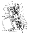
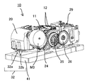
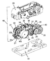
図1は本発明によるインクジェット記録装置の内部構成を示す模式的斜視図であり、図2は図1のインクジェット記録装置の回復手段を含む回復装置を斜め上方から見た模式的斜視図であり、図3は本発明によるインクジェット記録装置(図1のインクジェット記録装置)に搭載された回復装置の内部構造を示す模式的分解斜視図である。
【0034】
図1〜図3において、インクジェット記録装置1は、駆動源であるキャリッジモータM1と、インクジェット記録ヘッド3を搭載するキャリッジ2と、キャリッジモータM1によりキャリッジ2を矢印A方向に往復移動させる伝動機構4と、被記録媒体である記録紙P搬送(紙送り)する給紙機構(紙送り機構)5と、記録ヘッド3の吐出回復処理を行うために吐出口面をメンテナンスする回復装置10とを備えている。
【0035】
このようなインクジェット記録装置1においては、記録紙Pは給紙機構5によって送り込まれ、記録ヘッド3によって記録紙Pに所定の記録が行なわれる。
【0036】
キャリッジ2に装着されるインクジェットカートリッジ6は、該記録ヘッドが搭載される部材であるキャリッジ2に着脱自在に保持(装着)されている。
【0037】
記録ヘッド3に対しては、前記インクジェットカートリッジ6内に収容されたインクが供給される。
【0038】
この場合、キャリッジ2と記録ヘッド3は、両部材の接合面が適正に接触されて所要の電気的接続を達成維持できるようになっている。
【0039】
前記記録ヘッド3は、記録信号に応じてエネルギーを印加することにより、複数の吐出口からインクを選択的に吐出して記録するインクジェット記録ヘッドである。
【0040】
また、この記録ヘッド3は、熱エネルギーを利用してインクを吐出するインクジェット記録手段であって、熱エネルギーを発生するための電気熱変換体を備えたものである。
【0041】
さらに、前記記録ヘッド3は、前記電気熱変換体によって印加される熱エネルギーにより生じる膜沸騰による気泡の成長、収縮によって生じる圧力変化を利用して、吐出口よりインクを吐出させ、記録を行うものである。
【0042】
前記電気熱変換体は各吐出口のそれぞれに対応して設けられ、記録信号に応じて対応する電気熱変換体にパルス電圧を印加することによって対応する吐出口からインクを吐出するものである。
【0043】
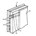
図17は、記録手段(記録ヘッド)3のインク吐出部(一つの吐出口列)の構造を模式的に示す部分斜視図である。
【0044】
図17において、被記録媒体(記録紙等)Pと所定の隙間(例えば、約0.3〜2.0ミリ程度)をおいて対面する吐出口面23には、所定のピッチで複数の吐出口49が形成され、共通液室50と各吐出口49とを連通する各液路51の壁面に沿ってインク吐出用のエネルギーを発生するための電気熱変換体(発熱抵抗体など)52が配設されている。
【0045】
記録ヘッド3は、前記吐出口49が主走査移動方向(キャリッジ2に搭載される本実施例では該キャリッジ2の移動方向矢印A)と交叉する方向に並ぶような位置関係で案内支持されている。
【0046】
こうして、画像信号または吐出信号に基づいて対応する電気熱変換体52を駆動(パルス電圧を印加)して、液路51内のインクを膜沸騰させ、その時に発生する圧力によって吐出口49からインク滴を吐出させる記録手段(記録ヘッド)3が構成されている。
【0047】
図1において、キャリッジ2は、キャリッジモータM1の駆動力を伝達する伝動機構4の駆動ベルト7の一部に連結されており、ガイドシャフト13に沿って矢印A方向に摺動自在に案内支持されており、前記キャリッジモータM1によって駆動されるように装着されている。
【0048】
従って、キャリッジ2は、キャリッジモータM1の正転及び逆転によってガイドシャフト13に沿って往復移動する。
【0049】
また、8はキャリア2の矢印A方向における絶対位置を示すスケールであり、本実施の形態では、透明なPETフィルムに必要なピッチで黒色のバーを印刷したものを用いており、その一方はシャーシ9に固着され、他方は不図示の板バネで支持されている。
【0050】
図示のインクジェット記録装置1においては、記録ヘッド3の不図示の吐出口が形成された吐出口面に対向して不図示のプラテンが設けられており、キャリッジモータM1の駆動力によって記録ヘッド3を搭載したキャリッジ2が往復駆動されると同時に、記録ヘッド3に記録信号を与えてインクを吐出することによって、プラテン上に搬送された被記録媒体としての記録紙Pの全幅にわたって記録が行われる。
【0051】
14は記録シートを搬送するために搬送モータM2によって駆動される搬送ローラであり、15は不図示のバネにより記録シートを搬送ローラ14に当接するピンチローラ、16はピンチローラ15を回転自在に支持するピンチローラホルダである。
【0052】
また、17は搬送ローラ14の一端に固着された搬送ローラギアであり、この搬送ローラギア17に中間ギア18を介して伝達された搬送モータM2の回転により、搬送ローラ14が駆動されるようになっている。
【0053】
19は記録ヘッド3によって画像が形成された記録シートを記録装置外ヘ排出するための不図示の排出ローラに固着された排出ローラギアであり、この排出ローラギア19に中間ギア18を介して伝達された搬送モータM2の回転により、排出ローラ20が駆動されるようになっている。
【0054】
なお、21は排出ローラ20に記録シートを不図示のバネにより圧接する拍車ローラであり、22は拍車ローラ21を回転自在に支持する拍車ホルダである。
【0055】
また、このようなインクジェット記録装置1においては、記録ヘッド3を搭載するキャリッジ2の記録動作のための往復運動の範囲外(記録領域外)の所望位置(例えばホームポジションと対応する位置)に、記録ヘッド3の吐出不良を回復するための回復装置を配設することが行われている。
【0056】
このような回復装置は、一般に、記録ヘッド3の吐出口面をキャッピングするキャッピング手段11と記録ヘッド3の吐出口面をクリーニングするワイピング手段12を備えており、このキャッピング手段11による吐出口面のキャッピングに連動して回復装置内の不図示の吸引手段(吸引ポンプ等)により吐出口からインクを強制的に排出させ、それによって、記録ヘッド3のインク流路内の増粘インクや気泡等を除去するなどの吐出回復処理を行うことができる。
【0057】
また、非記録時等に、記録ヘッド3の吐出口面をキャッピングすることによって、該記録ヘッドを保護するとともにインクの乾燥を防止することができる。
【0058】
また、ワイピング手段12はキャッピング手段11の近傍に配されると共に、記録ヘッド3の吐出口面に付着したインク滴を拭き取るようになっている。
【0059】
そして、これらキャッピング手段11及びワイピング手段12により、記録ヘッド3を正常な状態に保つことが可能となっている。
【0060】
図2及び3、4において、本発明における回復手段を含む回復装置の構成の一例を説明する。
【0061】
本回復装置は、記録ヘッド3の不吐不良等の回復手段として吸引手段48、キャッピング手段11、ワイピング手段12を備えている。
【0062】
図13に示す吸引手段48は回復ベース20の円弧部内面をガイド面としその円弧面に沿わせるように吸引チューブ32を2本配置し、吸引チューブ32を不図示の加圧ばねで押圧し吸引チューブ32内に負圧を発生させるための加圧コロ33を吸引動作中は吸引チューブ32を押圧する側へ、吸引動作以外は吸引チューブ32から退避させ得るように加圧コロホルダ31に長穴形状を設けその長穴形状に軸支し、1本の吸引チューブ32に対し2個配置している。
【0063】
本実施例では加圧コロ33の配置は吸引チューブ32をガイドする回復ベース20の円弧面が半円形状であるため、加圧コロ33を180度対向するように2個配置することにより1個の加圧コロが吸引チューブ32を押圧している状態から離間する時に、もう一方の加圧コロ33が吸引チューブ32を押圧するようになるため2個の加圧コロ33を連続的に回転させることで吸引チューブ内の負圧を保ちつつ連続的に吸引動作を行うことが可能になる。
【0064】
また、ガイド形状がほぼ円上になっている場合は1個の加圧コロでも同様の効果が得られる。
【0065】
さらに、ガイド形状が半円状でも加圧コロが2個以上であれば同じように連続的に吸引動作が可能である。
【0066】
図6に示すように、前記加圧コロホルダ31は加圧コロホルダガイド30に回復ベース20の円弧ガイド面半径方向に回動可能に軸支され加圧コロ33を吸引チューブ32に対し押圧、退避させる働きをする。
【0067】
加圧コロホルダガイド30は両端部に軸を有し、回復ベース20の吸引チューブ32が備えられている半円弧ガイド面の円弧中心に軸支され、PGモータM3からの駆動を伝達し回転可能に配置されている。
【0068】
PGモータM3からの駆動力は吸引手段48にPGギア1 24、ポンプギア27を伝わり加圧コロホルダガイド30を回転させ吸引回復動作を実行する。
【0069】
また、吸引手段48はPGモータM3の回転駆動に対し直結された形になっており、PGモータM3の一方向回転(以降正転)で吸引動作、逆方向回転(以降逆転)で加圧コロ33を吸引チューブ32への押圧状態から解除方向へ移動させる働きを得る構成となっている。
【0070】
本実施例においては、吸引手段48を駆動させる駆動源を回復装置内にもつ1駆動源としているが、他の別の駆動源を利用して吸引手段48を駆動させても良い。
【0071】
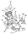
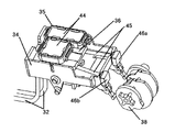
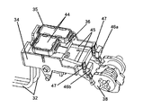
図4に示す通り、キャッピング手段11は記録ヘッド3の吐出口面に当接するキャップ35と、記録ヘッド3の吐出口面から排出されるインクを効率よく吸引するためのキャップ吸収体44と、キャップを支え圧縮ばね43により記録ヘッド3の吐出口面にキャップ35を圧接させ得るキャップホルダ36と、キャップホルダ36にキャップ圧を与える圧縮ばね43を支持し、キャップホルダ36を上下方向に摺動自在に支持するキャップベース34と、キャップ35を記録ヘッド3の吐出口面に当接、離間させるためのアーム部材となるキャップレバー37と、図9〜12に示すキャップ35とキャップベース34に設けた大気連通孔47とを連結する大気連通チューブ45、大気連通孔47を開閉することでキャップ35内部に密閉状態を作ったり、開放状態にさせ得る大気連通弁46a、46bにより構成されている。
【0072】
キャッピング手段11には吸引手段48を構成している吸引チューブ32がキャップホルダ36に備えたジョイント部に連結され、キャップ手段が記録ヘッド3の吐出口面に当接している間、吸引手段48の吸引動作によりキャップ35内に負圧を与え記録ヘッド3からインクを吸引可能に構成している。
【0073】
本実施例においてキャッピング手段11を記録ヘッド3に当接させるための昇降動作および大気開放弁46a、46bの開閉動作はPGモータM3からの駆動をPGギア2 25、PGギア3 26らを経由し、キャッピング手段11の昇降動作および大気連通弁46a、46bの開閉動作を実行するカム38に係合しPGモータM3からの駆動力を一方向回転時はカム38に伝達し、他方向回転時は空転しカム38に駆動を伝達させないワンウエイクラッチギア28を伝達して駆動力を受ける構成としている。
【0074】
前記カム38は前述のキャッピング手段の動作のほかに、ワイピング手段12を駆動させることや記録ヘッド3の回復動作中に記録ヘッド3と本実施例における回復ユニットを構成するキャッピング手段11との位置決めとして備えられているCRロックレバー29の昇降動作も制御するように構成している。
【0075】
前述した各手段の動作はカム38に備えられたカム位置検知センサ用フラグとカム位置検知センサ40とでカム38の回転位置決めを行い、各手段を制御している。
【0076】
ここで本発明は、吐出口からインクを吐出する複数のノズルおよびノズル列を有する記録手段と、記録手段を搭載して往復運動をするキャリッジと、前記吐出口からのインクの吐出状態を回復または維持するための回復手段と、を有するインクジェット記録装置に係るものであり、上記に加えてさらに、従来例に対し以下に説明するような特徴的な構成を包蔵するものである。
【0077】
すなわち、次に図5〜図13を参照して本発明によるインクジェット記録装置の回復装置の特徴的な吸引回復手段に設けられたインク排出管、および廃インク保持手段の配置の特徴について説明する。
【0078】
本発明の実施例における回復装置により記録ヘッド3の吸引回復動作を行う場合、図16に示すフローのようなシーケンスにより吸引回復を行う。
【0079】
図16に示すフローは本実施例における回復装置の一般的な吸引回復動作を示している。
【0080】
図16に示す吸引命令は記録ヘッド3に備えられた吐出口からどの程度インクが吐出されたかによって発せられるものであったり、意図的に吸引動作をさせたい時に発せられるものである。
【0081】
以下図16のフローに沿って本実施例における吸引回復動作を説明する。
【0082】
吸引回復動作命令が下された場合、回復ユニットを構成しているカム38の位置をカム位置検知センサ40により検出し、キャッピング手段11及びワイピング手段12等の位置を確認する。
【0083】
記録ヘッド3が吸引回復動作ポジションにいない状態の場合は、記録ヘッド3と回復ユニットを構成しているキャッピング手段11やワイピング手段12等が干渉しない状態にあることをカム位置検出センサ40により確認した後で記録ヘッド3を図1に示す伝達機構4を駆動させ吸引回復動作ポジションに移動させる。
【0084】
その後PGモータM3の駆動によりカム38を駆動させることで吸引回復動作を実行するためキャッピング手段11を記録ヘッド3の吐出口面へカム38の回転により当接させる。
【0085】
その際のPGモータM3の回転方向は図13に示す回転方向Rであるため吸引手段48の加圧コロ33は吸引チューブ32から離間した位置に配置され、キャップ35内を大気と連通させており吸引手段48が回転してもキャップ35内に吸引チューブ32内に残留するインクを逆流させたり、キャップ35内に正の圧力をかけ、記録ヘッド3の吐出口にダメージを与えないように構成している。
【0086】
キャップ35を記録ヘッド3の吐出口面に当接させた後、吸引回復動作に入る準備として吸引手段48を構成する加圧コロ33を一度吸引チューブ32に押圧させるためPGモータM3を吸引手段48が図13に示す回転方向L側に回転する方向の駆動をあたえる(図16における加圧コロ吸引前イニシャル動作)。
【0087】
次に、本実施例の回復装置ではBkインク及びColorインクに対して各々吸引回復設定をしているため吸引モードの選択を行う。
【0088】
吸引モードの選択はキャッピング手段11を構成する大気開放弁46a、46bをキャップ35が記録ヘッド3に当接している間に開閉することでキャップ35内部を密閉状態や大気連通状態にし、吸引手段48の吸引回転動作により密閉空間となっているキャップ35内部に負圧を与え記録ヘッド3よりインクを排出させる側のキャップを制御することで行っている。
【0089】
図9は記録ヘッド3の吐出口面を保護するキャッピング状態の時の弁の位置を示し、図10は吸引回復動作準備(前述の加圧コロ吸引前イニシャル動作)を行う際にキャップ35内を大気連通状態およびキャップ35内のインクを排出する空吸引状態の場合の弁の位置を示し、図11は本実施例における回復装置のBkインク吸引状態の弁の位置を示し、同様に図12はColorインク吸引状態の弁の位置を示している。
【0090】
吸引モードの選択を行った後にPGモータM3の駆動を吸引手段48へ伝達させBk、Color各々の吸引命令にあわせて所定の吸引回復設定量のインク吸引回復を行う。
【0091】
その後、キャップ35内にためられた吸引された廃インクをキャップ35内から排出するために、図10に示すように大気開放弁46a、46bをカム38の回転により開放状態にさせる。
【0092】
前記大気開放弁46a、46bの状態にした後、吸引手段48は吸引回復動作させる方向の駆動をPGモータM3より伝達されキャップ35内のインクを回復装置外へ排出する空吸引動作を実行し、キャップ35内にあったインクは吸引チューブ32を通じて排出され廃インク保持手段を構成する廃インク吸収体41へと吸収される。
【0093】
前述の一般的な吸引回復動作は、本実施例においてBkインクの単独吸引モード、Colorインクの単独吸引モード、Bk、Colorインクの連続吸引モードの基本制御であり、この吸引回復動作を組み合わせることで各種吸引モードに対応している。
【0094】
処で、前述してきた吸引回復動作を正常にかつ安定的に実行するために本発明では以下に説明する構成をとっている。
【0095】
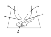
図5、図6及び図7に示す本実施例の回復装置は、顔料系Bk廃インク排出管32aの廃インク排出口54と染料系Color廃インク排出管32bの廃インク排出口55を廃インク排出管ガイド42により近接させた位置に配置させることで、各モードの吸引動作が行われた際に、廃インク排出管の廃インク排出口付近に顔料系Bkインクと染料系Colorインクが混合するようにし、Bkインクの固着による堆積を防止している。
【0096】
前述の構成をとることで図8に示すようにBk廃インク排出管32aの廃インク排出口54付近に堆積しかけたBk固着インク80(顔料系インク)にColorの廃インク(染料系インク)が混合し易くなりBk固着インク80を溶解し、固着による堆積を抑制可能となる。
【0097】
この場合、BkとColorが混在するようなパターンの印字を行う際はある頻度でBkインク吸引回復とColorインク吸引回復が同時あるいは交互に行われることでBk廃インクの固着を抑制できるのだが、Bkインクのみを使用するパターンの印字を繰り返し行うようであるとその頻度に合わせてBkのみの吸引動作しか入らず、Bk廃インク排出管32aの廃インク排出口54付近に結果としてBk固着インク80が堆積してしまう状況は従来の回復装置と同様に思われる。
【0098】
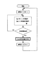
そこで、本発明の実施例では図15のフローチャートに示すように記録ヘッド3に備えられた吐出口がある一定時間印字に使用されていない場合、定期的にインク吸引回復を行うようにし、そのインク吸引回復を行うタイミングをBk廃インクが完全に固着し堆積してしまう前にすることで定期的にColorインク吸引回復を行い、Bk固着インク溶解を可能にし、Bk廃インク固着を抑制する効果を生み出せるようシーケンスを組んでいる。
【0099】
前述の構成にすることで、Bk廃インクが固着し堆積しはじめる前にColorインク(染料系インク)をBkインク(顔料系インク)に混在させることができBk固着インク堆積を抑制することが可能になる。
【0100】
また、本発明の実施例では、前述してきた構成に加え、従来の回復装置では図20に示すように廃インク排出管の廃インク排出口位置は廃インク吸収体41に対し廃インクを吸収し易くするねらいから比較的近接したところに配置していたのに対し、より効率よくBk廃インクとColor廃インクを混在させ、Bk固着インク溶解を促すために図7に示すように廃インク吸収体41と回復装置に備えられた廃インク排出管32a、32bを配置するようにしている。
【0101】
この配置はBk、Color廃インクがすぐに廃インク吸収体に吸収されること無く十分混合させられたあとに混合した廃インクが廃インク吸収体に吸収されるよう、かつBkインクのみ単独で廃インク吸収体に吸収されBkインクが吸収された先の廃インク吸収体の目詰まり等を防止すべくある程度廃インク吸収体と各廃インク排出管の廃インク排出口を放すように構成している。
【0102】
この構成により、固着していたBk廃インクがColor廃インクにより溶解され、その溶解液が廃インク吸収体に吸収されることで廃インク吸収体内部での目詰まりを抑制し、より効率的に廃インクを廃インク吸収体へ吸収可能になる。
【0103】
図14は本発明のその他の実施例を示す模式図である。
【0104】
図14に示す構成によれば、Color廃インク排出管57をBk廃インク排出管56の上方に配置することで確実にBk廃インクたまりの上からColor廃インクを滴下することができ、Bk廃インクとColor廃インクの混合が効率よく行え、Bk廃インク固着抑制可能である。
【0105】
また、図14に示すように廃インク排出口58、59を傾斜させる事によりColorの廃インク排出口59から出てきたColor廃インクが廃インク排出口を伝わり、Bk廃インク排出口58へ流れるため、Bk廃インク排出口近傍でのBk廃インク固着70を抑制することが可能となる。
【0106】
前述してきた構成によれば、本発明における本実施例の回復装置はより効率的に廃インク保持手段へ廃インクを吸収させかつ廃インク排出口のインクつまりを防止し、吐出回復性能を維持可能で安定的な回復手段を持つインクジェット記録装置を提供することができる。
【0107】
なお、以上の実施例では、記録手段を被記録媒体に対して相対移動させながら記録するシリアル記録方式のインクジェット記録装置を例に挙げて説明したが、本発明は、被記録媒体の全幅または一部をカバーする長さのラインタイプの記録手段を用いて副走査のみで記録するライン記録方式のインクジェット記録装置に対しても同様に適用することができ、同様の効果を達成し得るものである。
【0108】
また、本発明は、1個の記録手段を用いる記録装置、異なる色のインクで記録する複数の記録手段を用いるカラー記録装置、あるいは同一色彩で異なる濃度で記録する複数の記録手段を用いる階調記録装置、さらには、これらを組み合わせた記録装置の場合にも、同様に適用することができ、同様の効果を達成し得るものである。
【0109】
さらに、本発明は、記録ヘッドとインクタンクを一体化した交換可能なインクカートリッジを用いる構成、記録ヘッドとインクタンクを別体にし、その間をインク供給用のチューブ等で接続する構成など、記録ヘッドとインクタンクの配置構成がどのような場合にも同様に適用することができ、同様の効果が得られるものである。
【0110】
なお、本発明は、インクジェット記録装置が、例えば、ピエゾ素子等の電気機械変換体等を用いる記録手段を使用するものである場合にも適用できるが、中でも、熱エネルギーを利用してインクを吐出する方式の記録手段を使用するインクジェット記録装置において優れた効果をもたらすものである。
【0111】
【発明の効果】
以上の説明から明らかなごとく、本発明は、顔料系廃インクに染料系廃インクを重ね合わせ排出することで顔料系インクの廃インクが固着し堆積するのを抑制し、より効率的に廃インク保持手段へ廃インクを吸収させ、かつ、廃インク排出口のインクつまりを防止し、吐出回復性能を維持可能で安定的な回復手段を持つインクジェット記録装置を提供することができる。
【図面の簡単な説明】
【図1】 本発明によるインクジェット記録装置の内部を示す模式的斜視図
【図2】 本発明によるインクジェット記録装置の回復装置(回復手段)の模式的斜視図
【図3】 図2における回復装置の内部構造を示す模式的分解斜視図
【図4】 本発明による回復装置の内部構造キャップ手段を示す模式的分解斜視図
【図5】 本発明による回復手段と廃インク排出管の廃インク排出口の位置を示す模式的側面図
【図6】 本発明による回復手段と廃インク排出管の廃インク排出口の位置を示す模式的正面図
【図7】 本発明による廃インク排出管の廃インク排出口の位置と廃インク吸収体の位置を示す模式的底面図
【図8】 本発明による廃インク排出管から排出される廃インクとその堆積インクの溶解状態を説明した模式的上斜視図
【図9】 本発明による回復ユニットのキャッピング手段を構成する大気連通弁のBk,及びColor側両弁とも閉じている状態(キャップクローズ状態)を示す模式的斜視図
【図10】 図9に示すキャッピング手段を構成する大気連通弁の両弁とも開放状態(空吸引状態)にある時を示す模式的斜視図
【図11】 図9に示すキャッピング手段を構成する大気連通弁のうちColor側の弁が開放し、Bk側の弁が閉じている状態(Bk吸引状態)を示す模式的斜視図
【図12】 図9に示すキャッピング手段を構成する大気連通弁のうちBk側の弁が開放し、Color側の弁が閉じている状態(Color吸引状態)を示す模式的斜視図
【図13】 図2及び3に示す本実施例における吸引手段の詳細を表す側面図
【図14】 本発明による他の実施例における廃インク排出管の位置を示す模式的正面図
【図15】 本発明による吸引回復動作を行うタイミングの一例を示すフローチャート
【図16】 本発明による回復装置における一般的な吸引回復動作シーケンスを示すフローチャート
【図17】 図1中の記録手段におけるインク吐出部の構造を模式的に示す部分斜視図
【図18】 従来例における廃インク排出管の位置を示す模式的底面図
【図19】 従来例における回復装置と廃インク排出管の位置を示す模式的斜視図
【図20】 従来例における廃インク排出管から排出される廃インクとその堆積インクの状態を説明する模式的上斜視図
【符号の説明】
1 インクジェット記録装置
2 キャリッジ
3 記録手段(記録ヘッド)
4 伝動機構
5 給紙機構
6 インクジェットカートリッジ
7 駆動ベルト
8 スケール
9 シャーシ
10 回復装置
11 キャッピング手段
12 ワイピング手段
13 ガイドシャフト
14 搬送ローラ
15 ピンチローラ
16 ピンチローラガイド
17 搬送ローラギア
18 中間ギア
19 排出ローラギア
20 回復ベース
21 拍車ローラ
22 拍車ホルダ
23 吐出口面
24 PGギア1
25 PGギア2
26 PGギア3
27 ポンプギア
28 ワンウエイクラッチギア
29 CRロックレバー
30 加圧コロホルダガイド
31 加圧コロホルダ
32 吸引チューブ(廃インク排出管)
32a Bk廃インク排出管
32b Color廃インク排出管
33 加圧コロ
34 キャップベース
35 キャップ
36 キャップホルダ
37 キャップレバー
38 カム
39 キャップレバー付勢ばね
40 カム位置検知センサ
41 廃インク吸収体
42 廃インク排出管ガイド
43 圧縮ばね
44 キャップ吸収体
45 大気連通チューブ
46a 大気連通弁a
46b 大気連通弁b
47 大気連通孔
48 吸引手段(吸引ポンプ)
49 吐出口
50 共通液室
51 液路
52 電気熱変換体
53 大気連通弁ばね
54 Bk廃インク排出口
55 Color廃インク排出口
56 第二実施例のBk廃インク排出管
57 第二実施例のColor廃インク排出管
58 第二実施例のBk廃インク排出口
59 第二実施例のColor廃インク排出口
60 顔料系Bk堆積固着インク
61 染料系Color廃インク
62 従来例のBk廃インク排出口
63 従来例のColor廃インク排出口
70 顔料系Bk廃インクと染料系Color廃インクの混合廃インク
80 顔料系Bk固着インク
A キャリッジ走査方向
L チューブポンプコロ加圧回転方向
M1 キャリッジモータ
M2 搬送モータ
M3 回復用モータ
P 記録媒体
R チューブポンプコロ解除回転方向[0001]
BACKGROUND OF THE INVENTION
The present invention relates to an ink jet recording apparatus that performs recording by discharging ink from a recording unit to a recording material.
[0002]
[Prior art]
2. Description of the Related Art Conventionally, printing apparatuses that perform printing on printing media (hereinafter, also simply referred to as “recording paper”) such as paper, cloth, plastic sheets, and OHP sheets have various printing methods such as wire dot methods, thermal methods, It has been proposed as a form capable of mounting a print head by a thermal transfer method or an ink jet method.
[0003]
Among such printing apparatuses, an inkjet printing system printing apparatus (hereinafter also referred to as an inkjet printing apparatus) that prints on recording paper by ejecting ink from an ink ejection port is a low-noise non-impact printing system. Yes, it is possible to perform high-density and high-speed printing operations.
[0004]
In general, an ink jet printing apparatus includes means for driving a carrier on which a print head is mounted, transport means for transporting recording paper, and control means for controlling these.
[0005]
On the other hand, as an energy generating element that generates energy used to eject ink from the ink ejection port of the print head, an element using an electromechanical transducer such as a piezo element, or heat generated by irradiating an electromagnetic wave such as a laser In addition, there are those that discharge ink droplets by the action of heat generation, and those that heat a liquid by an electrothermal transducer element having a heating resistor.
[0006]
Among them, an ink jet print type print head that uses thermal energy to eject ink as droplets can perform high-resolution printing because ink discharge ports can be arranged at high density.
[0007]
Among them, print heads that use electrothermal transducer elements as energy generating elements are easy to miniaturize and have the advantages of IC technology and microfabrication technology that have made significant progress in technology and improved reliability in the recent semiconductor field. It is advantageous because it can be fully utilized for manufacturing, easy to mount with high density, and inexpensive to manufacture.
[0008]
As described above, the ink jet printing method is an extremely excellent printing method having a simple configuration, but there is a problem to be solved.
[0009]
Ink jet recording apparatus, when the entire apparatus is not used for a long period of time, or when a specific discharge port among a large number of discharge ports rarely discharges compared to other discharge ports even if used, Ink may increase in viscosity due to evaporation of moisture in the ejection port or in the ink chamber communicating with the ejection port, resulting in ejection failure.
[0010]
In addition, ink droplets, water droplets, dust, or the like may adhere to the ejection surface of the head provided with the ejection port, and the ejected ink droplets may be pulled by these adhered materials, thereby deflecting the ejection direction. is there.
[0011]
In order to prevent these problems, the conventional ink jet recording apparatus includes the following means as a so-called ejection recovery apparatus.
[0012]
For example, as non-ejection prevention means, pre-ejection that ejects ink onto a predetermined ink receiving medium before printing and recording to remove thickened ink, or adhering substances by sucking ink from the ejection port or common liquid chamber Ink suction for removing ink, ink suction for removing air bubbles mixed at the time of ink tank replacement, and capping for preventing evaporation of ink moisture from the ejection port have been performed.
[0013]
In addition, in an inkjet recording apparatus capable of recording a color image, a plurality of ejection port groups such as magenta, cyan, and yellow are provided in addition to black in the same recording head, and an independent ink tank and a supply are provided for each ejection port group. An apparatus having a system and a cap and other discharge recovery means common to each group has been developed.
[0014]
In this type of recording device, the types of black ink and color ink have been changed in recent years from the viewpoint of black color development and color printing color reproducibility, that is, black ink is pigment-based ink, and color ink is dye-based. Ink has come to be adopted, and due to the difference in the properties of each ink, it has come to have a cap dedicated to pigmented ink and ink suction recovery means, a cap dedicated to dye-based ink and ink suction recovery means .
[0015]
In this case, black ink discharge recovery and color ink discharge recovery are performed separately, and each ink is discharged from a separate discharge port, and the discharge ports are located at different positions. Has been placed.
[0016]
As a conventional example, FIGS. 18 to 20 are schematic views showing the position of the waste ink discharge pipe of the recovery device.
[0017]
In this conventional recovery device, especially when printing a pattern using only pigment-based Bk ink, Bk ink is suctioned independently for maintenance of the discharge port according to the frequency, and almost all of the dye-based Color ink is sucked. Not done.
[0018]
Therefore, as shown in FIG. 20, the waste
[0019]
If such a state further progresses, the suction operation of the recovery device cannot sufficiently draw out ink from the ejection port, and there is a possibility that maintenance of the ejection port cannot be sufficiently performed.
[0020]
[Problems to be solved by the invention]
In short, as shown in FIG. 20, because of the nature of the pigment ink, it is very easy to fix compared to the dye ink, so that the pigment ink is located around the waste ink discharge port of the discharge pipe that discharges the pigment ink sucked by the discharge recovery means. The fixed material accumulates and the solid material grows up, blocking the waste ink discharge port to deteriorate the discharge recovery performance, or after being absorbed by the waste ink holding means, it starts to adhere to the absorbed part and retains the waste ink. There is a problem that it becomes difficult to absorb ink from the surface layer in the vicinity of the means.
[0021]
Therefore, the present invention has been made in view of such technical problems, and an object of the present invention is to fix and deposit the waste ink of the pigment-based ink by superimposing and discharging the dye-based waste ink on the pigment-based waste ink. An ink jet recording apparatus having a stable recovery means that can suppress discharge, more efficiently absorb waste ink into the waste ink holding means, prevent ink clogging at the waste ink discharge port, and maintain discharge recovery performance. Is to provide.
[0022]
[Means for Solving the Problems]
In order to solve the above-described problems, the present invention provides a first cap for capping a pigment ink discharge portion that discharges pigment ink, and a first ink discharge pipe for discharging ink from the first cap. A second cap for capping a dye ink discharge portion for discharging the dye ink, a second ink discharge pipe for discharging the ink from the second cap, and the first ink discharge pipe And an absorber for absorbing ink discharged from the discharge port of the second ink discharge pipe. An ink jet recording apparatus comprising: a discharge opening of the second ink discharge pipe with respect to the absorber. A guide member is provided for supporting the first ink discharge pipe and the second ink discharge pipe so that the outlet is disposed above the discharge port of the first ink discharge pipe. Make .
[0031]
DETAILED DESCRIPTION OF THE INVENTION
Embodiments of the present invention will be described below with reference to the drawings.
[0032]
Throughout the drawings, the same reference numerals indicate the same or corresponding parts.
[0033]
FIG. 1 is a schematic perspective view showing an internal configuration of an ink jet recording apparatus according to the present invention, and FIG. 2 is a schematic perspective view of a recovery device including recovery means of the ink jet recording apparatus of FIG. FIG. 3 is a schematic exploded perspective view showing the internal structure of the recovery device mounted on the ink jet recording apparatus (the ink jet recording apparatus of FIG. 1) according to the present invention.
[0034]
1 to 3, an ink
[0035]
In such an ink
[0036]
The
[0037]
Ink stored in the
[0038]
In this case, the
[0039]
The
[0040]
The
[0041]
Further, the
[0042]
The electrothermal converter is provided corresponding to each of the discharge ports, and discharges ink from the corresponding discharge port by applying a pulse voltage to the corresponding electrothermal converter in accordance with a recording signal.
[0043]
FIG. 17 is a partial perspective view schematically showing the structure of the ink ejection section (one ejection port array) of the recording means (recording head) 3.
[0044]
In FIG. 17, a plurality of discharges are provided at a predetermined pitch on the
[0045]
The
[0046]
In this way, the corresponding
[0047]
In FIG. 1, the
[0048]
Accordingly, the
[0049]
Reference numeral 8 denotes a scale indicating the absolute position of the
[0050]
In the illustrated ink
[0051]
[0052]
Reference numeral 17 denotes a transport roller gear fixed to one end of the
[0053]
[0054]
A
[0055]
Further, in such an ink
[0056]
Such a recovery device generally includes a
[0057]
Further, by capping the ejection port surface of the
[0058]
The wiping means 12 is disposed in the vicinity of the capping means 11 and wipes ink droplets adhering to the discharge port surface of the
[0059]
The capping
[0060]
2, 3 and 4, an example of the configuration of the recovery device including the recovery means in the present invention will be described.
[0061]
The recovery apparatus includes a
[0062]
The suction means 48 shown in FIG. 13 uses the inner surface of the arc portion of the
[0063]
In this embodiment, the
[0064]
Further, when the guide shape is substantially circular, the same effect can be obtained with one pressure roller.
[0065]
Furthermore, even if the guide shape is semicircular, if the pressure roller is two or more, the suction operation can be continuously performed in the same manner.
[0066]
As shown in FIG. 6, the
[0067]
The pressure
[0068]
The driving force from the PG motor M3 is transmitted to the suction means 48 through the PG gear 124 and the
[0069]
Further, the suction means 48 is directly connected to the rotational drive of the PG motor M3. The suction operation is performed by one-way rotation (hereinafter referred to as forward rotation) of the PG motor M3, and the pressure roller is rotated by reverse rotation (hereinafter referred to as reverse rotation). It has the structure which acquires the function which moves 33 to the cancellation | release direction from the press state to the
[0070]
In the present embodiment, the drive source for driving the suction means 48 is one drive source in the recovery device, but the suction means 48 may be driven using another drive source.
[0071]
As shown in FIG. 4, the capping
[0072]
The capping
[0073]
In this embodiment, the raising / lowering operation for bringing the
[0074]
In addition to the operation of the capping means described above, the
[0075]
In the operation of each means described above, the
[0076]
Here, the present invention relates to a recording unit having a plurality of nozzles and nozzle arrays for ejecting ink from the ejection port, a carriage mounted with the recording unit and reciprocating, and an ink ejection state from the ejection port. In addition to the above, in addition to the above, a characteristic configuration as described below is included in the conventional example.
[0077]
That is, with reference to FIGS. 5 to 13, the characteristics of the arrangement of the ink discharge pipe and the waste ink holding means provided in the characteristic suction recovery means of the recovery device of the ink jet recording apparatus according to the present invention will be described.
[0078]
When performing the suction recovery operation of the
[0079]
The flow shown in FIG. 16 shows a general suction recovery operation of the recovery device in this embodiment.
[0080]
The suction command shown in FIG. 16 is issued depending on how much ink is ejected from the ejection port provided in the
[0081]
Hereinafter, the suction recovery operation in the present embodiment will be described along the flow of FIG.
[0082]
When a suction recovery operation command is issued, the position of the
[0083]
When the
[0084]
Thereafter, the
[0085]
At this time, the rotation direction of the PG motor M3 is the rotation direction R shown in FIG. 13, so that the
[0086]
After the
[0087]
Next, in the recovery device of this embodiment, the suction mode is selected for Bk ink and Color ink, so the suction mode is selected.
[0088]
The suction mode is selected by opening and closing the
[0089]
FIG. 9 shows the position of the valve in the capping state for protecting the discharge port surface of the
[0090]
After selecting the suction mode, the drive of the PG motor M3 is transmitted to the suction means 48, and ink suction recovery of a predetermined suction recovery set amount is performed in accordance with the suction commands of Bk and Color.
[0091]
Thereafter, in order to discharge the sucked waste ink collected in the
[0092]
After the
[0093]
The general suction recovery operation described above is the basic control of the Bk ink single suction mode, the color ink single suction mode, and the Bk and color ink continuous suction mode in this embodiment, and this suction recovery operation is combined. It corresponds to various suction modes.
[0094]
By the way, in order to normally and stably execute the above-described suction recovery operation, the present invention adopts the configuration described below.
[0095]
The recovery device of this embodiment shown in FIGS. 5, 6 and 7 uses the waste
[0096]
By adopting the above-described configuration, as shown in FIG. 8, the color waste ink (dye ink) is added to the Bk fixing ink 80 (pigment ink) that has accumulated near the waste
[0097]
In this case, when printing a pattern in which Bk and Color are mixed, the Bk ink suction recovery and the Color ink suction recovery are performed simultaneously or alternately at a certain frequency. If printing of a pattern using only Bk ink is repeatedly performed, only the suction operation of Bk is entered in accordance with the frequency, and as a result, the Bk fixed
[0098]
Therefore, in the embodiment of the present invention, as shown in the flowchart of FIG. 15, when the ejection port provided in the
[0099]
With the above-described configuration, Color ink (dye-based ink) can be mixed with Bk ink (pigment-based ink) before Bk waste ink starts to adhere and accumulate, and Bk fixed ink accumulation can be suppressed. become.
[0100]
Further, in the embodiment of the present invention, in addition to the configuration described above, the conventional recovery device is not illustrated. 20 As shown in FIG. 2, the waste ink discharge port position of the waste ink discharge pipe is disposed relatively close to the
[0101]
This arrangement allows Bk and Color waste ink to be absorbed by the waste ink absorber after it has been sufficiently mixed without being immediately absorbed by the waste ink absorber, and only Bk ink is discarded alone. The waste ink absorber and the waste ink discharge port of each waste ink discharge pipe are released to some extent in order to prevent clogging of the waste ink absorber that has been absorbed by the ink absorber and the Bk ink has been absorbed. .
[0102]
With this configuration, the fixed Bk waste ink is dissolved by the Color waste ink, and the solution is absorbed by the waste ink absorber, thereby suppressing clogging inside the waste ink absorber and more efficiently. The waste ink can be absorbed by the waste ink absorber.
[0103]
FIG. 14 is a schematic view showing another embodiment of the present invention.
[0104]
According to the configuration shown in FIG. 14, by disposing the Color waste
[0105]
Further, as shown in FIG. 14, by tilting the waste
[0106]
According to the configuration described above, the recovery device of the present embodiment of the present invention can more efficiently absorb the waste ink to the waste ink holding means and prevent the ink from being clogged at the waste ink discharge port, thereby maintaining the discharge recovery performance. In addition, an ink jet recording apparatus having a stable recovery means can be provided.
[0107]
In the above-described embodiments, the serial recording type inkjet recording apparatus that records while moving the recording unit relative to the recording medium has been described as an example. The present invention can be similarly applied to a line recording type ink jet recording apparatus that records only by sub-scanning using a line-type recording means having a length that covers a portion, and the same effect can be achieved. .
[0108]
The present invention also provides a gradation using a recording apparatus using a single recording means, a color recording apparatus using a plurality of recording means for recording with different color inks, or a plurality of recording means for recording with the same color and different densities. The present invention can be similarly applied to a recording apparatus and further to a recording apparatus that combines these, and the same effect can be achieved.
[0109]
Further, the present invention provides a recording head including a configuration using a replaceable ink cartridge in which a recording head and an ink tank are integrated, a configuration in which the recording head and the ink tank are separated, and a connection between them using an ink supply tube or the like. The present invention can be similarly applied to any arrangement of the ink tanks, and the same effect can be obtained.
[0110]
The present invention can also be applied to a case where the ink jet recording apparatus uses a recording means that uses an electromechanical transducer such as a piezo element. In particular, the ink is ejected using thermal energy. In the ink jet recording apparatus using the recording means of the above system, an excellent effect is brought about.
[0111]
【The invention's effect】
As is clear from the above description, the present invention suppresses the waste ink of the pigment-based ink from adhering and depositing by superimposing and discharging the dye-based waste ink on the pigment-based waste ink, and more efficiently waste ink. It is possible to provide an ink jet recording apparatus having a stable recovery means that absorbs waste ink to the holding means, prevents ink clogging at the waste ink discharge port, can maintain discharge recovery performance.
[Brief description of the drawings]
FIG. 1 is a schematic perspective view showing the inside of an ink jet recording apparatus according to the present invention.
FIG. 2 is a schematic perspective view of a recovery device (recovery means) of an ink jet recording apparatus according to the present invention.
3 is a schematic exploded perspective view showing the internal structure of the recovery device in FIG. 2;
FIG. 4 is a schematic exploded perspective view showing the internal structure cap means of the recovery device according to the present invention.
FIG. 5 is a schematic side view showing the position of the recovery means and the waste ink discharge port of the waste ink discharge pipe according to the present invention.
FIG. 6 is a schematic front view showing the position of the recovery means and the waste ink discharge port of the waste ink discharge pipe according to the present invention.
FIG. 7 is a schematic bottom view showing a position of a waste ink discharge port and a position of a waste ink absorber of a waste ink discharge pipe according to the present invention.
FIG. 8 is a schematic top perspective view illustrating a state of dissolution of waste ink discharged from a waste ink discharge pipe according to the present invention and its accumulated ink.
FIG. 9 is a schematic perspective view showing a state (cap closed state) in which both the Bk and Color side valves of the atmospheric communication valve constituting the capping means of the recovery unit according to the present invention are closed.
10 is a schematic perspective view showing when both of the atmospheric communication valves constituting the capping means shown in FIG. 9 are in an open state (empty suction state).
FIG. 11 is a schematic perspective view showing a state in which the Color side valve is open and the Bk side valve is closed (Bk suction state) among the atmospheric communication valves constituting the capping means shown in FIG. 9;
12 is a schematic perspective view showing a state in which the Bk side valve is open and the Color side valve is closed (Color suction state) among the atmospheric communication valves constituting the capping means shown in FIG. 9;
13 is a side view showing details of the suction means in the present embodiment shown in FIGS. 2 and 3. FIG.
FIG. 14 is a schematic front view showing the position of a waste ink discharge pipe in another embodiment according to the present invention.
FIG. 15 is a flowchart showing an example of timing for performing a suction recovery operation according to the present invention.
FIG. 16 is a flowchart showing a general suction recovery operation sequence in the recovery device according to the present invention.
FIG. 17 is a partial perspective view schematically showing the structure of an ink discharge portion in the recording means in FIG.
FIG. 18 is a schematic bottom view showing the position of a waste ink discharge pipe in a conventional example.
FIG. 19 is a schematic perspective view showing the positions of a recovery device and a waste ink discharge pipe in a conventional example.
FIG. 20 is a schematic top perspective view illustrating a state of waste ink discharged from a waste ink discharge pipe and a state of the accumulated ink in a conventional example.
[Explanation of symbols]
1 Inkjet recording device
2 Carriage
3 Recording means (recording head)
4 Transmission mechanism
5 Paper feed mechanism
6 Inkjet cartridge
7 Drive belt
8 scale
9 Chassis
10 Recovery device
11 Capping means
12 Wiping means
13 Guide shaft
14 Transport roller
15 Pinch roller
16 Pinch roller guide
17 Conveyor roller gear
18 Intermediate gear
19 Discharge roller gear
20 Recovery base
21 Spur Roller
22 spur holder
23 Discharge port surface
24
25
26
27 Pump gear
28 One-way clutch gear
29 CR lock lever
30 Pressure roller holder guide
31 Pressure roller holder
32 Suction tube (waste ink discharge tube)
32a Bk waste ink discharge pipe
32b Color waste ink discharge pipe
33 Pressure roller
34 Cap base
35 cap
36 Cap holder
37 Cap lever
38 cams
39 Cap lever biasing spring
40 Cam position detection sensor
41 Waste ink absorber
42 Waste ink discharge pipe guide
43 Compression spring
44 Cap absorber
45 Atmospheric communication tube
46a Air communication valve a
46b Air communication valve b
47 Air communication hole
48 Suction means (suction pump)
49 Discharge port
50 Common liquid chamber
51 liquid channel
52 Electrothermal converter
53 Atmospheric valve spring
54 Bk waste ink outlet
55 Color waste ink outlet
56 Bk waste ink discharge pipe of the second embodiment
57 Color waste ink discharge pipe of the second embodiment
58 Bk waste ink outlet of the second embodiment
59 Color waste ink outlet of the second embodiment
60 Pigment-based Bk deposition fixing ink
61 Dye-based Color waste ink
62 Conventional Bk waste ink outlet
63 Color waste ink outlet of the conventional example
70 Mixed waste ink of pigment-based Bk waste ink and dye-based Color waste ink
80 Pigment-based Bk fixing ink
A Carriage scanning direction
L Tube pump roller pressure rotation direction
M1 Carriage motor
M2 transport motor
M3 recovery motor
P Recording medium
R Tube pump roller release rotation direction
Claims (3)
該第1のキャップからインクを排出するための第1のインク排出管と、
染料インクを吐出する染料インク吐出部をキャッピングするための第2のキャップと、
該第2のキャップからインクを排出するための第2のインク排出管と、
前記第1のインク排出管の排出口及び前記第2のインク排出管の排出口から排出されたインクを吸収するための吸収体と、
を備えるインクジェット記録装置において、
前記吸収体に対して、前記第2のインク排出管の排出口が前記第1のインク排出管の排出口の上方に配置されるように前記第1のインク排出管及び前記第2のインク排出管を支持するガイド部材を備えることを特徴とするインクジェット記録装置。 A first cap for capping a pigment ink discharge portion for discharging the pigment ink;
A first ink discharge tube for discharging ink from the first cap;
A second cap for capping the dye ink discharge portion for discharging the dye ink;
A second ink discharge tube for discharging ink from the second cap;
An absorber for absorbing ink discharged from the discharge port of the first ink discharge tube and the discharge port of the second ink discharge tube;
In an inkjet recording apparatus comprising:
With respect to the absorber, the first ink discharge pipe and the second ink discharge are so arranged that the discharge port of the second ink discharge pipe is disposed above the discharge port of the first ink discharge pipe. An ink jet recording apparatus comprising a guide member for supporting a tube .
Priority Applications (2)
| Application Number | Priority Date | Filing Date | Title |
|---|---|---|---|
| JP2001024666A JP4669133B2 (en) | 2001-01-31 | 2001-01-31 | Inkjet recording device |
| US10/059,017 US6722755B2 (en) | 2001-01-31 | 2002-01-30 | Ink-jet recording apparatus |
Applications Claiming Priority (1)
| Application Number | Priority Date | Filing Date | Title |
|---|---|---|---|
| JP2001024666A JP4669133B2 (en) | 2001-01-31 | 2001-01-31 | Inkjet recording device |
Publications (3)
| Publication Number | Publication Date |
|---|---|
| JP2002225313A JP2002225313A (en) | 2002-08-14 |
| JP2002225313A5 JP2002225313A5 (en) | 2008-03-21 |
| JP4669133B2 true JP4669133B2 (en) | 2011-04-13 |
Family
ID=18889771
Family Applications (1)
| Application Number | Title | Priority Date | Filing Date |
|---|---|---|---|
| JP2001024666A Expired - Fee Related JP4669133B2 (en) | 2001-01-31 | 2001-01-31 | Inkjet recording device |
Country Status (2)
| Country | Link |
|---|---|
| US (1) | US6722755B2 (en) |
| JP (1) | JP4669133B2 (en) |
Families Citing this family (8)
| Publication number | Priority date | Publication date | Assignee | Title |
|---|---|---|---|---|
| US7204577B2 (en) | 2002-06-11 | 2007-04-17 | Seiko Epson Corporaion | Waste liquid treating device and liquid ejecting apparatus incorporating the same |
| JP4579485B2 (en) * | 2002-06-24 | 2010-11-10 | セイコーエプソン株式会社 | Printing apparatus having a plurality of print heads |
| US8152273B2 (en) | 2005-06-30 | 2012-04-10 | Canon Kabushiki Kaisha | Waste ink absorbent member, and waste ink container and ink jet recording apparatus equipped with waste ink absorbent member |
| JP4710587B2 (en) * | 2005-12-15 | 2011-06-29 | ブラザー工業株式会社 | Inkjet printer |
| JP4755956B2 (en) | 2006-08-28 | 2011-08-24 | 株式会社リコー | Inkjet recording device |
| JP2008207452A (en) | 2007-02-27 | 2008-09-11 | Ricoh Co Ltd | Image forming device |
| US8783824B2 (en) * | 2007-09-27 | 2014-07-22 | Canon Kabushiki Kaisha | Capping unit for ink jet recording unit |
| US8277006B2 (en) * | 2010-02-24 | 2012-10-02 | Eastman Kodak Company | Controllable maintenance operations for efficient ink use |
Citations (4)
| Publication number | Priority date | Publication date | Assignee | Title |
|---|---|---|---|---|
| JPH0930004A (en) * | 1995-07-24 | 1997-02-04 | Canon Inc | Ink jet recording apparatus and cleaning method thereof |
| JP2000015832A (en) * | 1998-06-30 | 2000-01-18 | Canon Inc | Ink jet recorder |
| JP2000289214A (en) * | 1999-04-05 | 2000-10-17 | Canon Inc | Ink jet recorder |
| JP2000334981A (en) * | 1999-05-27 | 2000-12-05 | Canon Inc | Ink jet recorder |
Family Cites Families (6)
| Publication number | Priority date | Publication date | Assignee | Title |
|---|---|---|---|---|
| ES2053215T3 (en) * | 1990-02-13 | 1994-07-16 | Canon Kk | PRINTING DEVICE FOR INKS OF INK. |
| JPH0516391A (en) * | 1991-07-17 | 1993-01-26 | Canon Inc | Ink jet recording device |
| US5712668A (en) * | 1994-03-25 | 1998-01-27 | Hewlett-Packard Company | Rotary Multi-ridge capping system for inkjet printheads |
| US6447095B1 (en) | 1994-05-19 | 2002-09-10 | Canon Kabushiki Kaisha | Discharge recovery method for ink jet apparatus using waterproof ink and ink jet apparatus employing the method |
| EP0699534B1 (en) | 1994-09-02 | 2002-04-03 | Canon Kabushiki Kaisha | Ink jet apparatus and a waste liquid absorbing method |
| JP3555347B2 (en) * | 1996-08-20 | 2004-08-18 | 富士ゼロックス株式会社 | Ink-jet type image forming apparatus |
-
2001
- 2001-01-31 JP JP2001024666A patent/JP4669133B2/en not_active Expired - Fee Related
-
2002
- 2002-01-30 US US10/059,017 patent/US6722755B2/en not_active Expired - Fee Related
Patent Citations (4)
| Publication number | Priority date | Publication date | Assignee | Title |
|---|---|---|---|---|
| JPH0930004A (en) * | 1995-07-24 | 1997-02-04 | Canon Inc | Ink jet recording apparatus and cleaning method thereof |
| JP2000015832A (en) * | 1998-06-30 | 2000-01-18 | Canon Inc | Ink jet recorder |
| JP2000289214A (en) * | 1999-04-05 | 2000-10-17 | Canon Inc | Ink jet recorder |
| JP2000334981A (en) * | 1999-05-27 | 2000-12-05 | Canon Inc | Ink jet recorder |
Also Published As
| Publication number | Publication date |
|---|---|
| US6722755B2 (en) | 2004-04-20 |
| JP2002225313A (en) | 2002-08-14 |
| US20020101471A1 (en) | 2002-08-01 |
Similar Documents
| Publication | Publication Date | Title |
|---|---|---|
| JP3827302B2 (en) | Inkjet recording device | |
| JP2004090233A (en) | Inkjet recorder | |
| JPH05345415A (en) | Ink jet recording apparatus | |
| JP4154190B2 (en) | Inkjet recording device | |
| US7926905B2 (en) | Ink jet recording apparatus | |
| JP4669133B2 (en) | Inkjet recording device | |
| JP2002036603A (en) | Ink jet recorder | |
| JP2003001858A (en) | Ink jet recorder and recovery system unit thereof | |
| JPH07101082A (en) | Ink jet head and ink jet recording device | |
| JP4681714B2 (en) | Inkjet recording device | |
| JP2002036578A (en) | Ink jet recording apparatus | |
| JP2005111686A (en) | Inkjet recording apparatus | |
| JP2000238293A (en) | Ink jet printer | |
| JP2003080720A (en) | Ink jet recorder, blade cleaning device and blade cleaner | |
| JP2002137407A (en) | Ink jet recorder | |
| JP4794780B2 (en) | Ink jet recording apparatus and recovery method of the apparatus | |
| JP2005131791A (en) | Ink jet head and ink jet recorder | |
| JP2003103805A (en) | Ink jet recorder and recovery unit | |
| JP2004160800A (en) | Inkjet recording device | |
| JP2005111690A (en) | Cap for inkjet recording head, and inkjet recording apparatus | |
| JP2006068994A (en) | Inkjet recorder | |
| JP2000015832A (en) | Ink jet recorder | |
| JP2006181810A (en) | Inkjet printer | |
| JP2821955B2 (en) | Ink jet recording device | |
| JP2004160945A (en) | Inkjet recorder |
Legal Events
| Date | Code | Title | Description |
|---|---|---|---|
| A521 | Written amendment |
Free format text: JAPANESE INTERMEDIATE CODE: A523 Effective date: 20080130 |
|
| A621 | Written request for application examination |
Free format text: JAPANESE INTERMEDIATE CODE: A621 Effective date: 20080130 |
|
| A977 | Report on retrieval |
Free format text: JAPANESE INTERMEDIATE CODE: A971007 Effective date: 20101013 |
|
| A131 | Notification of reasons for refusal |
Free format text: JAPANESE INTERMEDIATE CODE: A131 Effective date: 20101019 |
|
| A521 | Written amendment |
Free format text: JAPANESE INTERMEDIATE CODE: A523 Effective date: 20101210 |
|
| TRDD | Decision of grant or rejection written | ||
| A01 | Written decision to grant a patent or to grant a registration (utility model) |
Free format text: JAPANESE INTERMEDIATE CODE: A01 Effective date: 20110111 |
|
| A01 | Written decision to grant a patent or to grant a registration (utility model) |
Free format text: JAPANESE INTERMEDIATE CODE: A01 |
|
| A61 | First payment of annual fees (during grant procedure) |
Free format text: JAPANESE INTERMEDIATE CODE: A61 Effective date: 20110114 |
|
| FPAY | Renewal fee payment (event date is renewal date of database) |
Free format text: PAYMENT UNTIL: 20140121 Year of fee payment: 3 |
|
| R150 | Certificate of patent or registration of utility model |
Free format text: JAPANESE INTERMEDIATE CODE: R150 |
|
| LAPS | Cancellation because of no payment of annual fees |