JP4681714B2 - Inkjet recording device - Google Patents
Inkjet recording device Download PDFInfo
- Publication number
- JP4681714B2 JP4681714B2 JP2000221089A JP2000221089A JP4681714B2 JP 4681714 B2 JP4681714 B2 JP 4681714B2 JP 2000221089 A JP2000221089 A JP 2000221089A JP 2000221089 A JP2000221089 A JP 2000221089A JP 4681714 B2 JP4681714 B2 JP 4681714B2
- Authority
- JP
- Japan
- Prior art keywords
- suction
- cap
- motor
- roller
- recording
- Prior art date
- Legal status (The legal status is an assumption and is not a legal conclusion. Google has not performed a legal analysis and makes no representation as to the accuracy of the status listed.)
- Expired - Fee Related
Links
Images


Description
【0001】
【発明の属する技術分野】
本発明は記録手段から被記録材へインクを吐出して記録を行うインクジェット記録装置に関する。
【0002】
【従来の技術】
従来、紙、布、プラスチックシート、OHP用シートなどの被記録材(記録媒体、プリント媒体、単に記録紙ともいう)に対して記録(プリント、印刷等)を行う記録装置(プリント装置等)として、種々の記録方式、例えばワイヤードット方式、感熱方式、熱転写方式、又はインクジェット方式による記録手段(記録ヘッド、プリントヘッド)を用いて記録するものが提案されている。
【0003】
そのような記録装置の中で、吐出口からインクを吐出させて被記録材(記録用紙)上に記録を行うインクジェット記録方式の記録装置(以下、インクジェット装置ともいう)は、低騒音なノンインパクト型の記録方式であり、高密度かつ高速な記録動作を行うことが可能である。一般に広く普及しているシリアルタイプのインクジェット記録装置は、記録ヘッド(記録手段)を搭載するキャリッジを駆動するキャリッジ駆動手段と、記録部を通して被記録材(記録用紙)を搬送(紙送り)する搬送機構駆動手段と、これらを制御するための駆動系制御手段とを備えている。
【0004】
一方、記録ヘッド(記録手段)の吐出口からインクを吐出するために利用されるエネルギーを発生するエネルギー発生素子としては、ピエゾ素子などの電気機械変換体を用いたもの、レーザーなどの電磁波を照射して発熱させ、この発熱による作用でインク滴を吐出させるもの、あるいは発熱抵抗体を有する電気熱変換体素子によって液体を加熱させるものなどがある。その中でも熱エネルギーを利用してインクを滴として吐出させる方式のインクジェット記録方式の記録ヘッドは、吐出口を高密度に配列することができるため高解像度の記録を行うことが可能である。その中でも、電気熱変換体素子をエネルギー発生素子として用いた記録ヘッドは、小型化も容易であり、かつ最近の半導体分野における技術の進歩と信頼性の向上が著しいIC技術やマイクロ加工技術の長所を十分に活用して製造でき、高密度実装化が容易で製造コストも廉価なことから、有利である。
【0005】
上述のように、インクジェット記録方式は簡単な構成から成る極めて優れた記録方式であるが、一方には解決すべき技術的課題も存在する。インクジェット記録装置の技術的課題の一つに吐出口の目詰まりがあるが、この目詰まりを解消する手段として、一般には、ポンプ手段を用いて記録ヘッドの吐出口からインクを吸引排出させたり加圧排出させたりすることにより吐出口のインク吐出性能を維持回復させる回復処理手段(回復ユニット)が使用されている。具体的には、インクを吸引排出させる回復手段においては、吐出口(ノズル先端)から吸引ポンプでインクを吸引することにより、記録ヘッド内及び記録系にインクを供給する流路内に存在する高粘度のインク(増粘インク)や微細なゴミやインク液中の気泡などをインクとともに吐出口より吸引排出するという処理が行われる。このような吸引回復動作を実行するためには、吸引キャップの開閉動作や吸引ポンプのオンオフ動作を行う必要がある。
【0006】
そのための手段として、先ず、吸引キャップの開閉動作を記録ヘッドを搭載したキャリッジの駆動手段を利用して行う構成のもの、つまり、吸引キャップ開閉ポジションにキャリッジを移動させることにより、キャップ手段上に備えたボス等をキャリッジに係合させてキャップを記録ヘッドの吐出口面へ当接させて吐出口をキャッピングする構成のものがある。さらに、複数の吸引回復モードを持ったり、記録ヘッドをキャッピング中にキャップ内と大気を連通させる手段としての吸引選択共用の大気連通弁等を設けているインクジェット記録装置については、同様にキャリッジを駆動させる手段を利用してキャップ内を大気と連通させる大気連通ポジションへキャリッジを移動させることで対応している。また、吸引ポンプの動作は被記録材(記録紙)搬送用の駆動源を一時的に利用することで吸引回復動作等に対応している。前述のような回復手段(回復ユニット)の構成は一般的に広く知れわたっており、従来のインクジェット記録装置の回復装置に広く用いられている。
【0007】
【発明が解決しようとする課題】
しかし、前述したような吸引キャップの当接離間ポジションや大気連通弁の開閉ポジション等を有するインクジェット記録装置は、これらの各ポジションの数に応じてキャリッジ移動方向の装着本体幅が広がってしまい、装着本体のサイズが大きくなってしまう。また、吸引手段としての吸引ポンプを被記録材搬送用(記録紙搬送用)の駆動源から駆動力伝達を行う場合、記録紙搬送中と吸引回復中とで駆動を切換える駆動伝達切換機構が必要になりその駆動伝達切換機構のスペース分さらに装置本体のサイズが大きくなったり、複数の吸引動作モード等を制御しなければならないことから駆動伝達切換機構自体複雑になって部品点数増加によるコストUPを招いてしまう。そこで、一つの駆動源の正逆回転で複数の回復動作を任意に行うことができるインクジェット記録装置用回復ユニットを提供することが重要な解決すべき技術的課題となっている。
【0008】
本発明はこのような技術的課題に鑑みてなされたものであり、本発明は、回復装置内に持つ一つの駆動源によりインクジェット記録装置の記録手段のメインテナンスに係わる回復装置(回復ユニット)の全ての動作を駆動制御させ、他の駆動源からの駆動伝達切換機構に依存することなく安定的にメインテナンス動作を行えるインクジェット記録装置を提供しようとするものである。
また、本発明は、回復動作を行う上で他の駆動源からの伝達切換機構を有しない回復装置内完結型ユニットを実現することで、省スペース型のインクジェット記録装置に容易に搭載可能な(発展性のある)回復ユニットを提供することである。
【0009】
すなわち、本発明の目的は、他の駆動源からの駆動力に依存することなく、回復ユニット内の一つの駆動源により複数の吸引回復モードを選択して行うことができ、また、吸引回復終了後にキャップが吐出口面から十分退避するまで吸引手段の逆回転による正圧をかけるなどの従来の処理操作を不要にすることで、吸引回復動作中にキャップを吐出口面に当接した状態から動かす操作を無くすことができるインクジェット記録装置を提供することである。
【0010】
【課題を解決するための手段】
本発明は、上記目的を達成するため、インクを吐出して記録を行う記録ヘッドの吐出口面をキャッピングするためのキャップと、該キャップと連通する吸引チューブと、該吸引チューブを押圧し該吸引チューブ内に負圧を発生させるためのコロと、該コロを回転可能に支持するコロホルダと、前記キャップ内を大気連通状態または密閉状態に切り替えるための大気連通弁と、正逆転可能なモータと、を備え、前記モータが正転すると前記コロホルダが第1の方向に回転することによって前記コロが前記チューブに押圧されて前記チューブがしごかれ、前記モータが逆転すると前記コロホルダが前記第1の方向と反対の第2の方向に回転することによって前記チューブに対する前記コロの押圧が解除されるインクジェット記録装置であって、前記モータの回転方向が正転から逆転に切り替わったときに、前記モータの駆動が前記コロホルダに伝達される前に、前記大気連通弁が駆動されて前記キャップ内が前記大気連通状態から前記密閉状態に切り替わることを特徴とする。
【0012】
【発明の実施の形態】
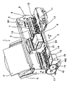
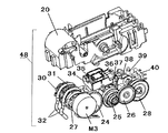
以下、図面を参照して本発明の実施の形態を具体的に説明する。なお、各図面を通して、同一符号は同一又は対応部分を示すものである。図1は本発明を適用した回復ユニットの一実施例を備えたインクジェット記録装置の概略構成を示す模式的斜視図であり、図2は図1のインクジェット記録装置の回復ユニット(本発明を適用した回復ユニットの一実施例)を斜め上方から見て示す模式的斜視図であり、図3は図2の回復ユニットの内部構造を適宜分解して示す模式的分解斜視図である。
【0013】
図1〜図3において、インクジェット記録装置1は、駆動源である駆動モータM1、M2と、記録手段としての記録ヘッド(インクジェット記録ヘッド)3を搭載するキャリッジ2と、駆動モータM1によりキャリッジ2を両矢印A方向に往復移動させる伝動機構4と、被記録材(被記録媒体)としての記録紙Pを給紙搬送(記録紙の送給及び搬送)を行う給紙機構5と、記録ヘッド3の吐出回復処理(インク吐出性能の維持回復、メインテナンス)を行うための回復ユニット(回復装置)10と、を備えている。このようなインクジェット記録装置1においては、記録紙Pは給紙機構5によって送り込まれ、記録ヘッド3によって該記録紙Pに所定の記録が行われる。記録ヘッド3にインクを供給するためのインクカートリッジ6は、記録ヘッド3が搭載される部材である前記キャリッジ2に着脱自在に保持(装着)されている。
【0014】
記録ヘッド3に対しては、前記インクカートリッジ6内に収容されたインクが供給される。この場合、キャリッジ2と記録ヘッド3は、両部材の接合面が適正に接触されて所要の電気的接続を達成維持できるようになっている。前記記録ヘッド3は、記録信号に応じてエネルギーを印加することにより、複数の吐出口からインクを選択的に吐出して記録するインクジェット記録ヘッドである。また、この記録ヘッド3は、熱エネルギーを利用してインクを吐出するインクジェット記録手段であって、熱エネルギーを発生するための電気熱変換体を備えたものである。さらに、前記記録ヘッド3は、前記電気熱変換体によって印加される熱エネルギーにより生じる膜沸騰による気泡の成長、収縮によって生じる圧力変化を利用して、吐出口よりインクを吐出させ、記録を行うものである。前記電気熱変換体は各吐出口のそれぞれに対応して設けられ、記録信号に応じて対応する電気熱変換体にパルス電圧を印加することによって対応する吐出口からインクを吐出するものである。
【0015】
図19は、記録手段(記録ヘッド)3のインク吐出部(一つの吐出口列)の構造を模式的に示す部分斜視図である。図19において、記録紙等の被記録材Pと所定の隙間(例えば、約0.3〜2.0ミリ程度)をおいて対面する吐出口面23には、所定のピッチで複数の吐出口49が形成され、共通液室50と各吐出口49とを連通する各液路51の壁面に沿ってインク吐出用のエネルギーを発生するための電気熱変換体(発熱抵抗体など)52が配設されている。記録ヘッド3は、前記吐出口49が主走査移動方向(キャリッジ2に搭載される本実施例では該キャリッジ2の移動方向、両矢印A方向)と交叉する方向に並ぶような位置関係で案内支持されている。こうして、画像信号または吐出信号に基づいて対応する電気熱変換体52を駆動(パルス電圧を印加)して、液路51内のインクを膜沸騰させ、その時に発生する圧力によって吐出口49からインクを吐出させる記録手段(記録ヘッド)3が構成されている。
【0016】
図1において、キャリッジ2は、駆動モータM1の駆動力を伝達する伝動機構4の駆動ベルト7の一部に連結されており、ガイドシャフト13に沿って両矢印A方向に摺動自在に案内支持されており、前記駆動モータM1によって駆動(往復動の駆動)されるように装着されている。従って、キャリッジ2は、駆動モータM1の正転及び逆転によってガイドシャフト13に沿って往復移動する。また、装置本体にはキャリッジ2の矢印A方向における絶対位置を示すスケール8が設けられている。本実施の形態では、このスケール8として、透明なPETフィルムに必要なピッチで黒色のバーを印刷したものが使用されており、その一方はシャーシ9に固着され、他方は不図示の板バネで支持されている。
【0017】
図示のインクジェット記録装置1においては、記録ヘッド3の吐出口49が形成された吐出口面23に対向して不図示のプラテンが設けられており、駆動モータM1の駆動力によって記録ヘッド3を搭載したキャリッジ2が往復駆動されると同時に、記録ヘッド3に記録信号を与えてインクを吐出することによって、プラテン上に搬送された被記録材としての記録紙Pの全幅にわたって記録が行われる。14は記録紙(記録シート)Pを搬送するために搬送モータM2によって駆動される搬送ローラであり、15は不図示のバネにより記録紙Pを搬送ローラ14に当接させるピンチローラであり、16はピンチローラ15を回転自在に支持するピンチローラホルダである。
【0018】
また、17は搬送ローラ14の一端に固着された搬送ローラギアであり、この搬送ローラギア17に中間ギア18を介して伝達された搬送モータM2の回転により、搬送ローラ14が駆動されるようになっている。19は記録ヘッド3によって画像が形成された記録シートを記録装置外へ排出するための不図示の排出ローラに固定された排出ローラギアであり、前記排出ローラは、前記排出ローラギア19に中間ギア18を介して伝達された搬送モータM2の回転により駆動されるようになっている。なお、21は前記排出ローラに記録シートPを不図示のバネにより圧接する拍車ローラであり、22は拍車ローラ21を回転自在に支持する拍車ホルダである。
【0019】
また、インクジェット記録装置1においては、記録ヘッド3を搭載するキャリッジ2の記録動作のための往復運動の範囲外(記録領域外)の所望位置(例えばホームポジションと対応する位置)に、記録ヘッド3のインク吐出性能を維持するとともに吐出不良が生じた場合にはこれを回復するための回復ユニット(回復装置)10が配設されている。この回復ユニット10には、記録ヘッド3の吐出口面23をキャッピングするキャッピング手段11、及び記録ヘッド3の吐出口面23をクリーニング(拭き取り清掃)するワイピング手段12が設けられている。そして、前記キャッピング手段11により吐出口面23をキャッピングして吐出口49を密閉した状態で、該キャッピング手段11に接続された吸引手段(吸引ポンプ等)を駆動することにより、吐出口49からインクを強制的に吸引して排出させる吸引回復処理が行われる。前記吸引手段(吸引ポンプ等)も、前記回復ユニット10内に設けられている。
【0020】
このような吸引回復処理によって、記録ヘッド3のインク流路内の増粘インクや気泡等を吐出口49から排出除去することで、該記録ヘッド3のインク吐出性能の維持回復が図られる。また、非記録時等に、記録ヘッド3の吐出口面23をキャッピングすることによって、該記録ヘッドを保護するとともにインクの乾燥を防止することができる。また、前記ワイピング手段12は、記録ヘッド3の吐出口面23に付着したインク滴や紙粉等を拭き取るためのものであり、キャッピング手段11の近傍に配置されている。そして、これらキャッピング手段11、ワイピング手段12及び前記吸引手段により、記録ヘッド3のインク吐出性能を正常な状態に保つことが可能となっている。
【0021】
図4は回復ユニット10の内部に設けられた伝動機構としてのギア列を示す模式的側面図である。図2、図3及び図4において、回復ユニット10は、記録ヘッド3の不吐出や吐出不良等の回復手段としての吸引手段48、キャッピング手段11、ワイピング手段12などを備えている。前記吸引手段48はチューブポンプで構成されている。このチューブポンプ(吸引手段)48は、回復ベース20の円弧部内面をガイド面としその円弧面に沿わせるように配置された2本の吸引チューブ32と、これらの吸引チューブ32に押圧されて該吸引チューブを押しつぶしながら転動することで該吸引チューブ32内に負圧を発生させる所定個数(本実施例では合計4個)の加圧コロ33と、を備えている。
【0022】
前記加圧コロ33は、不図示の加圧ばねで吸引チューブ32に押圧された状態で該吸引チューブ32に沿って転動することにより該吸引チューブ32をしごくように配設されている。また、前記加圧コロ33は、吸引動作中は吸引チューブ32を押圧する側へ付勢され、吸引動作以外では吸引チューブ32から退避できるように、加圧コロホルダ31に形成された長孔形状の溝に沿って移動可能に軸支されている。このような加圧コロ31は、本実施例では、1本の吸引チューブ32に対して2個配置されている。
【0023】
本実施例では、吸引チューブ32をガイドする回復ベース20の円弧面は中心角が約180度の略半円形状にされ、回転駆動される加圧コロホルダ31上の加圧コロ33は180度で対向するように2個配置されているので、一方のの加圧コロが吸引チューブ32を押圧している状態から離間する時に、他方の加圧コロ33が吸引チューブ32の押圧を開始することができ、従って、2個の加圧コロ33を連続的に回転させることで吸引チューブ32内の負圧を保ちつつ連続的に吸引動作を行うことができる。なお、吸引チューブ32のガイド面がほぼ円形(360度)をしている場合は、1個の加圧コロによっても同様に連続的に吸引動作を行うことができる。さらに、加圧コロを3個以上配設して連続的な吸引動作を行うように構成してもよい。
【0024】
加圧コロ33を軸支した前記加圧コロホルダ31は、加圧コロホルダガイド30に回復ベース20の円弧ガイド面半径方向に回動可能に軸支され、加圧コロ33を吸引チューブ32に対し押圧、退避させる働きをする。加圧コロホルダガイド30は、両端部に軸を有し、回復ベース20の吸引チューブ32が備えられている半円弧ガイド面の円弧中心に軸支され、駆動モータ(以降PGモータという)M3からの駆動を伝達し回転可能に配置されている。
【0025】
ここで、PGモータM3から吸引手段48への駆動力の伝達は、先ずPGギア24及びポンプギア27に伝達され、次いで、加圧コロホルダガイド30の回転軸に軸支されている該ポンプギア27を介して加圧コロホルダガイド30の片端面に配置されたポンプギアトリガボス41へ伝達され、さらに、該ポンプギアトリガボス41がポンプギア27の回転によりポンプギアトリガリブ42a、42bと当接することにより吸引手段48へ伝達されるという伝達経路により行われる。すなわち、PGモータM3からの駆動力は、吸引手段48に対し、PGギア24、ポンプギア27を伝わり、加圧コロホルダガイド30の回転軸にポンプギア27を軸支させ、さらに加圧コロホルダガイド30の片端面に配置されたポンプギアトリガボス41がポンプギア27の回転によりポンプギアトリガリブ42a、42bと当接した時に伝達されるようになっている。
【0026】
ここでポンプギア27の形状について説明を加えると、ポンプギア27は内部に2つのリブ(ポンプギアトリガリブ42a、42b)を備え、側面に空間が設けられ、この空間に入ってくるボス(ポンプトリガボス41)と前記両リブが当接することで駆動力を吸引手段48側へ伝達するような構成となっている。また、吸引手段48は、PGモータM3の回転駆動に対し直結された形になっており、PGモータM3の一方向回転(以降正転という)で吸引動作、逆方向回転(以降逆転という)で加圧コロ33を吸引チューブ32への押圧状態から解除方向へ移動させる働きを得る構成となっている。
【0027】
図5は本発明を適用した回復ユニットの一実施例における吸引手段としてのチューブポンプに対するポンプギアによる駆動伝達が解除された直後の状態を示す断面図であり、図6は図5のチューブポンプに対するポンプギアによる駆動が伝達される直前の状態を示す断面図であり、図6は図5のチューブポンプに対するポンプギアによる駆動が伝達され吸引動作が行われている状態を示す断面図である。
図8は本発明を適用した回復ユニットの一実施例における吸引手段としてのチューブポンプの加圧コロがチューブを押圧状態にありかつポンプギアによる駆動伝達が解除された直後の状態を示す断面図であり、図9は図8のチューブポンプに対するポンプギアによる駆動が伝達される直前の状態を示す断面図であり、図10は図9のチューブポンプに対するポンプギアによる駆動が伝達され加圧コロが解除状態となっている状態を示す断面図である。
【0028】
図11は本発明を適用した回復ユニットの一実施例におけるキャッピング手段のBk用大気連通弁及びColor用大気連通弁の両方が閉じている状態(キャップクローズ状態)を示す模式的斜視図であり、図12は図11の回復ユニットにおけるキャッピング手段のBk用大気連通弁及びColor用大気連通弁の両方が開放されている状態(空吸引、コロイニシヤル取り状態)を示す模式的斜視図であり、図13は図11の回復ユニットにおけるキャッピング手段の大気連通弁のうちColor用大気連通弁が開放されかつBk用大気連通弁が閉じている状態(Bk吸引状態)を示す模式的斜視図であり、図14は図11の回復ユニットにおけるキャッピング手段の大気連通弁のうちColor用大気連通弁が閉じかつBk用大気連通弁が開放されている状態(Color吸引状態)を示す模式的斜視図である。
図15は本発明を適用した回復ユニットの一実施例における吸引手段としてのチューブポンプの加圧コロが解除状態にありかつポンプギアによる駆動伝達が解除されている状態を示す断面図であり、図16は図15のチューブポンプがポンプギアによる駆動伝達を受けかつ吸引手段の加圧コロをチューブに押圧している状態を示す断面図である。
【0029】
さらに、図17は本発明を適用した回復ユニットの一実施例におけるキャッピング手段のキャップ及び大気連通弁の吸引モード選択動作時の各状態を示す図表であり、図18は本発明を適用した回復ユニットの一実施例における一般的な吸引回復動作のシーケンスを示すフローチャートである。以下に、図5〜図18を参照して、本発明を適用したインクジェット記録装置用回復ユニットの特徴的な構成及びその作用効果について更に具体的に説明する。
【0030】
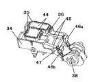
キャッピング手段11は、記録ヘッド3の吐出口面に当接するキャップ35と、図11に示す記録ヘッド3の吐出口面から排出されるインクを効率よく吸引するためのキャップ吸収体44と、キャップ35を支え不図示のキャップばねにより記録ヘッド3の吐出口面23にキャップ35を圧接させ得るキャップホルダ36と、キャップホルダ36に不図示のキャップばねでキャップ圧を与えるキャップばねを支持し、キャップホルダ36を上下方向に摺動自在に支持するキャップベース34と、キャップ35を記録ヘッド3の吐出口面23に当接、離間させるためのアーム部材として機能するキャッピング手段昇降レバー37と、キャップ35内部に密閉状態にしたり開放状態にするための大気連通弁46a、46b(図11〜図14参照)と、により構成されている。前記大気連通弁46a、46bは、図11〜図14に示すように、キャップ35とキャップベース34に設けた大気連通孔47とを連結する大気連通チューブ45を開閉することで、キャップ35内部を大気開放状態にしたり、該キャップ35内部に密閉状態を作ったりするものである。
【0031】
キャッピング手段11には、吸引手段48としてのチューブポンプを構成する吸引チューブ32がキャップホルダ36のジョイント部を介して連結されており、これによって、キャップ35が記録ヘッド3の吐出口面23に当接している間、吸引手段48の吸引動作によりキャップ35内に負圧を与え記録ヘッド3からインクを吸引排出することができる。本実施例では、Bkインクと Colorインクを別々の吸引チューブ32で吸引する構成としているため、キャップ35の閉空間を2個、キャップ吸収体44を閉空間に合わせて2個、大気連通チューブを2本、大気開放弁46a、46bを2個それぞれ配置している。キャッピング手段11を記録ヘッド3に当接させるための昇降動作、並びに大気開放弁46a、46bの開閉動作は、PGモータM3からの駆動力をPGギア25、26らを経由して伝達することにより行われる。
【0032】
このキャッピング手段11を記録ヘッド3に当接させるための昇降動作、並びに大気開放弁46a、46bの開閉動作は、キャッピング手段11の昇降動作及び大気連通弁46a、46bの開閉動作を実行するカム38に嵌合して該PGモータM3からの駆動力を一方向回転時はカム38に伝達し、他方向回転時は空転してカム38に駆動を伝達させないワンウエイ駆動伝達手段(ワンウエイクラッチギア)28を伝達して駆動力を受ける構成によって行われる。
【0033】
前記カム38は、前述のキャッピング手段11の動作の他に、ワイピング手段12の駆動及びCRロックレバー29の昇降動作を制御するためにも使用される。前記CRロックレバー29は、記録ヘッド3の回復動作中に、該記録ヘッド3と本実施例における回復ユニットを構成するキャッピング手段11との位置決めとして設けられたものであり、その昇降動作の制御も前記カム38を使用して行われる。前述したキャッピング手段11やワイピング手段12等の各手段の動作は、カム38に備えられたカム位置検知センサ用フラグとカム位置検知センサ40とでカム38の回転位置決めを行って各手段を制御することにより実行される。
【0034】
ここで、本発明を適用したインクジェット記録装置用回復ユニットの一実施例は、モータの一方向の駆動で吸引回復を行う吸引手段を駆動し、逆方向の駆動で、キャップを記録手段の吐出口面に当接・離間させるキャッピング手段11の駆動、あるいは該キャッピング手段11の駆動と吐出口面23をワイピングするワイピング手段12の駆動との両駆動を、位置検知用のフラグ部を同一軸上に有するカムとカム位相検知手段とにより駆動するように構成されており、これに加えて、以下に説明するような特徴的な構成を包蔵するものである。
【0035】
先ず、図5〜図18を参照して本発明を適用したインクジェット記録装置用回復ユニットの吸引回復モードについて説明する。本発明を適用した回復ユニット10の一実施例により記録ヘッド3の吸引回復動作を行う場合、図18に示すフローチャートのようなシーケンスにより吸引回復が行われる。図18に示すフローは本実施例における回復ユニットの一般的な吸引回復動作を示している。以下図18のフローに沿って本実施例における吸引回復モードの詳細を説明する。
【0036】
図18において、吸引回復動作命令が下された場合、回復ユニット10を構成しているカム38の位置をカム位相検知センサ40により検出し、キャッピング手段11及びワイピング手段12等の位置を確認する。記録ヘッド3が吸引回復動作ポジションにいない状態の場合は、記録ヘッド3と回復ユニット10を構成しているキャッピング手段11やワイピング手段12等とが干渉しない状態にあることをカム位置検出センサ40により確認した後で、図1に示す伝動機構4を駆動して記録ヘッド3を吸引回復動作ポジションに移動させる。その後PGモータM3の駆動によりカム38を駆動させることで吸引回復動作を実行するためキャッピング手段11を記録ヘッド3の吐出口面23へカム38の回転により当接させる。
【0037】
その際のPGモータM3の回転方向は図8〜図10に示す回転方向Rであるため、吸引手段48の加圧コロ33は図10に示すように吸引チューブ32から離間した位置に配置され、キャップ35内を大気と連通させており、吸引手段48が回転してもキャップ35内へ吸引チューブ32内に残留するインクを逆流させたり、キャップ35内に正の圧力をかけて記録ヘッド3の吐出口にダメージ(インク吐出上の不都合)を与えないように構成している。
【0038】
キャップ35を記録ヘッド3の吐出口面23に当接させた後、吸引回復動作に入る準備として、吸引手段48を構成する加圧コロ33を一度吸引チューブ32に押圧させるため、PGモータM3によって吸引手段48が回転方向L側へ回転する方向の駆動を与える。その際、キャッピング手段11は記録ヘッド3の吐出口面に当接しているので、吸引手段48が回転方向R側へ回転する時に余計な負圧をキャップ35内にかけることを防ぐため、キャップ35を記録ヘッド3に当接させた時にカム38の回転により大気開放弁46a、46bを開放状態にさせておく。PGモータM3の駆動により図5に示す状態からポンプギア27がL方向の回転力を受けることで図6に示す状態まで回転する。
【0039】
さらに回転を続けることで吸引手段48を構成している加圧コロホルダガイド30の軸にポンプギア27が軸支されている側の端面に配置されたポンプギアトリガボス41がポンプギア27の内側に備えられたポンプギアトリガリブ42bと当接し吸引手段48に回転力を伝達させ、図7に示すように吸引手段48を回転方向L側に回転させ、加圧コロ33を吸引チューブ32に押圧する状態にさせる(図15、図16)。この動作は吸引回復動作命令が入った時、加圧コロ33がどの位置にいても安定的な吸引回復動作を可能にするため、加圧コロ33の位置を吸引チューブ32に押圧させた状態にすることで、加圧コロ33が吸引チューブ32を押圧するまでの不感領域における吸引チューブ32の押しつぶし量すなわちインク吸引量のバラツキを抑える役割となっている。前述の動作をすることで加圧コロ33の位置検知に必要であった加圧コロセンサがなくともインク吸引量のバラツキを少なくし安定的な吸引回復動作が可能になる。
【0040】
次に、加圧コロ33を吸引チューブ32に押圧させた後、本実施例の回復ユニットでは吸引モードの選択を行う。吸引モードの選択は、キャッピング手段11の大気連通弁46a、46bをキャップ35が記録ヘッド3に当接している間に開閉することにより、キャップ35内部を密閉状態や大気連通状態にし、吸引手段48の吸引回復動作により密閉空間となっているキャップ35内部に負圧を与え記録ヘッド3よりインクを排出させる側のキャップを制御することで行っている。
【0041】
図11から図14に示すように大気連通弁46a、46bの位置により大気連通孔47を開放、密閉することでキャップ35内密閉開放制御をしている。図11は記録ヘッド3の吐出口面を保護するキャッピング状態の時の位置を示し、図12は吸引回復動作準備を行う際にキャップ35内を大気連通状態にするとともにキャップ35内のインクを排出する空吸引状態にする場合の弁の位置を示し、図13は本実施例における回復ユニット10のBkインク吸引状態の弁の位置を示し、同様に図14は Colorインク吸引状態の弁の位置を示している。
【0042】
前述の大気連通弁の動作も本実施例における回復ユニットに備えられたPGモータM3の1駆動源で行うため、吸引回復動作の準備として行った加圧コロ33の状態を崩さずに、大気連通弁の選択を行い吸引モードを選択しなくてはならない。そこで、図17に示すように記録ヘッド3にキャッピング手段11が当接している間はPGモータM3の駆動によりワンウエイ駆動伝達手段(ワンウエイクラッチギア)28を伝達してカム38を回転させ大気連通弁46a、46bを動作させる際、ポンプギア27に備えられたポンプギアトリガリブ42a、42bが吸引手段48を構成する加圧コロホルダガイド30の端面に設けられたポンプギアトリガボス41に当接して吸引手段48側にPGモータM3の駆動力を伝達しないように構成している。すなわち、PGモータM3によりカム38側へ駆動伝達されている状態で吸引モード選択中(図17の網掛け領域)は吸引手段48への伝達を解除するように構成している。
【0043】
よって、ポンプギア27に備えられているポンプギアトリガリブ42a、42bの間隔は吸引モード選択領域においてカム38の回転角度とPGモータM3から吸引手段48へ伝達するギアの減速比とカム38へ伝達するギアの減速比を考慮して図17に示す網掛け領域内でPGモータM3の駆動力を吸引手段48側へ伝達しない間隔としている。本実施例では、吸引選択モードの数に対し、ポンプギア27の持つリブは2本必要ではあるが、吸引選択モードの数やギアの減速比、カム38の回転量によってはポンプギア27に備えるポンプギアトリガリブの数は1本でもよい。また、本実施例の説明図ではポンプギア27に形成した空間を貫通した空間としたが、ポンプギア27の片側が閉じている形状、すなわちギアの肉抜き形状のようにしてトリガリブによる空間を構成してもよい。
【0044】
吸引モード選択を行った後、PGモータM3の駆動により吸引回復動作を行うよう吸引手段48側に駆動力を与える方向にモータを回転させ所定量のインクを吸引する吸引回復動作を行う。その後、キャップ35内に溜められた吸引された排インクをキャップ35内から排出するために、図12に示すように大気連通弁46a、46bをカム38の回転により開放状態にさせる。この大気連通弁の開動作の間に吸引手段48に駆動が伝達されてしまうと加圧コロ33が吸引チューブ32をキャップ35内にインクを逆流させる方向へと回転してしまい、インク逆流により記録ヘッド3にダメージを与えてしまうのだが、前述の動作の間においてもポンプギア27はポンプギアトリガリブ42a、42bが加圧コロホルダガイド30上のポンプギアトリガボス41との当接から離間する側へ回転駆動する構成となっているため、吸引手段48が回転することはなく、インク逆流による不具合を起こすことはない。
【0045】
前記大気連通弁46a、46bの連通状態にした後、吸引手段48は吸引回復動作させる方向の駆動をPGモータM3より伝達され、キャップ35内のインクを回復ユニット外へ排出する空吸引動作を実行し、一般的な吸引回復動作は終了する。前述の一般的な吸引回復動作は、本実施例においては、Bkインクの単独吸引モード、 Colorインクの単独吸引モード、Bk、 Colorインクの連続吸引モードの基本制御であり、この吸引回復動作を組み合わせることで各種吸引モードに対応している。
【0046】
前述したインクジェット記録装置用回復ユニットによれば、モータの一方向の駆動で吸引回復を行う吸引手段を駆動し、逆方向の駆動で、キャップを記録手段の吐出口面に当接・離間させるキャッピング手段又は該キャッピング手段と吐出口面をワイピングするワイピング手段との両方を、位置検知用のフラグ部を同一軸上に有するカムとカム位相検知手段とにより駆動可能であり、これによって、記録ヘッドのメインテナンスに関わる回復動作に対してユニット内完結型の回復ユニットを提供することができる。
【0047】
すなわち、以上説明した実施例によれば、記録手段から被記録材へインクを吐出して記録を行うインクジェット記録装置において、一つの駆動源の一方向の駆動で、インク吐出吸引回復を行う吸引手段を駆動するとともに、前記一つの駆動源の逆方向の駆動で、キャップを前記記録手段の吐出口面に当接及び離間させるキャッピング手段と、前記キャップが前記記録手段の吐出口面に当接している際に該キャップ内空間を密閉又は大気と連通させるための連通弁の開閉手段との両方を一つのカムにより駆動する構成を基本構成とするインクジェット記録装置用回復ユニットが提供される。そして、以下の述べるような特徴的な構成及び作用効果を有するインクジェット記録装置用回復ユニットが提供される。
【0048】
先ず、前記基本構成において、前記キャップが前記記録手段の吐出口面に当接しており、前記連通弁が所定の開閉動作を行っている間は前記吸引手段に前記駆動源より駆動力を伝達させず、前記吸引手段をある時間一定の位置に停止させておき、その間に複数の吸引回復モードを選択可能にし、前記駆動源から前記吸引手段に連結している1つのギアの側面に複数のリブにより空間を設け、前記ギアの前記空間に係合し、所定角度前記ギアが回転した後に前記吸引手段へ駆動力を伝達する伝達手段を持ち、前記駆動源の一方向の駆動により前記吸引手段がインク吐出吸引回復動作中には前記駆動源から前記キャッピング手段及び前記連通弁の開閉手段を駆動させる前記カムに駆動力を伝達解除させ、前記駆動源の逆方向の駆動により前記キャッピング手段及び前記連通弁の開閉手段を駆動させる前記カムに駆動を伝達するワンウエイ駆動伝達手段を持つ構成が採用されている。
【0049】
このような構成を採ることにより、他の駆動源からの駆動力に依存せず回復ユニット内の一つの駆動源でキャッピング中にキャップ内にチューブポンプ逆回転による正圧をかけることなく複数の吸引回復モード選択を行うことができる他、吸引ポンプが吸引回復動作中にはキャップ手段のキャップ部材は記録ヘッドの吐出口面に接している状態から動くことがなく、吸引回復終了後キャップ手段を記録ヘッドの吐出口面から退避させる時もキャップ部材が吐出口面から十分退避するまでチューブポンプの逆回転による正圧をかけないようにできる回復動作ユニット内完結型のインクジェット記録装置用回復ユニットが提供される。
【0050】
さらに、前記吸引手段を前記駆動源より回転駆動を得て記録手段の吐出口に通じるチューブを加圧コロで変形させることにより前記吐出口に負圧を発生させ、前記吐出口よりインクを排出させるチューブポンプであり、前記加圧コロがチューブ加圧回転方向とは逆側の駆動を与えられたとき、加圧コロがチューブ加圧力を緩和する方向へ移動する構成としたので、回復動作中の吸引回復動作以外の回復動作を行う際に、チューブポンプの逆回転によりチューブ内の残留インクやチューブ内の空気を逆流させることがないため、安定的な回復動作ユニット内完結型のインクジェット記録装置用回復ユニットが提供される。
【0051】
さらに、前記吸引手段を前記駆動源より回転駆動を得て記録手段の吐出口に通じるチューブを加圧コロで変形させることにより前記吐出口に負圧を発生させ、前記吐出口よりインクを排出させるチューブポンプとし、前記吸引手段によりインク吐出吸引回復を行う際に駆動源の一方向の駆動により前記大気連通弁を開放状態にさせ、逆方向の駆動により前記吸引手段を構成する加圧コロをチューブポンプの吸引チューブに押圧させた後に各吸引回復モードを選択し、各モードの吸引動作を行う構成としたので、常に吸引前の加圧コロの位置をチューブに押圧した状態から吸引動作に入ることができるため、前述の状態からチューブポンプの回転量を規定することでコロの位置検知用センサを持たずにバラツキの少ないインク吸引が可能となり、より安定的なインクジェット記録装置用回復ユニットが提供される。
【0052】
なお、以上の説明した実施例では、記録手段を被記録媒体に対して相対移動させながら記録するシリアル記録方式のインクジェット記録装置を例に挙げて説明したが、本発明は、被記録媒体の全幅又は一部をカバーする長さのラインタイプの記録手段を用いて副走査のみで記録するライン記録方式のインクジェット記録装置に対しても同様に適用することができ、同様の効果を達成し得るものである。また、本発明は、1個の記録手段を用いる記録装置、異なる色のインクで記録する複数の記録手段を用いるカラー記録装置、あるいは同一色彩で異なる濃度で記録する複数の記録手段を用いる階調記録装置、さらには、これらを組み合わせた記録装置の場合にも、同様に適用することができ、同様の効果を達成し得るものである。
【0053】
さらに、本発明は、記録ヘッドとインクタンクを一体化した交換可能なインクカートリッジを用いる構成、記録ヘッドとインクタンクを別体にし、その間をインク供給用のチューブ等で接続する構成など、記録ヘッドとインクタンクの配置構成がどのような場合にも同様に適用することができ、同様の効果が得られるものである。なお、本発明は、インクジェット記録装置が、例えば、ピエゾ素子等の電気機械変換体等を用いる記録手段を使用するものである場合にも適用できるが、中でも、熱エネルギーを利用してインクを吐出する方式の記録手段を使用するインクジェット記録装置において優れた効果をもたらすものである。かかる方式によれば、記録の高密度化、高精細化が達成できるからである。
【0054】
【発明の効果】
本発明によれば、他の駆動源からの駆動力に依存することなく、回復ユニット内の一つの駆動源により、キャッピング中にキャップ内に吸引手段の逆回転による正圧をかけるなどの操作を必要とせずに、複数の吸引回復モードを選択して行うことができ、また、吸引回復終了後にキャップが吐出口面から十分退避するまで吸引手段の逆回転による正圧をかけるなどの従来の処理操作を不要にすることで、吸引回復動作中にキャップを吐出口面に当接した状態から動かす操作を無くすことができるインクジェット記録装置が提供される。
【図面の簡単な説明】
【図1】本発明を適用した回復ユニットの一実施例を備えたインクジェット記録装置の概略構成を示す模式的斜視図である。
【図2】図2は図1のインクジェット記録装置の回復ユニットを斜め上方から見て示す模式的斜視図である。
【図3】図2の回復ユニットの内部構造を適宜分解して示す模式的分解斜視図である。
【図4】図2の回復ユニットの内部に設けられた伝動機構としてのギア列を示す模式的側面図である。
【図5】本発明を適用した回復ユニットの一実施例における吸引手段としてのチューブポンプに対するポンプギアによる駆動伝達が解除された直後の状態を示す断面図である。
【図6】図5のチューブポンプに対するポンプギアによる駆動が伝達される直前の状態を示す断面図である。
【図7】図5のチューブポンプに対するポンプギアによる駆動が伝達され吸引動作が行われている状態を示す断面図である。
【図8】本発明を適用した回復ユニットの一実施例における吸引手段としてのチューブポンプの加圧コロがチューブを押圧状態にありかつポンプギアによる駆動伝達が解除された直後の状態を示す断面図である。
【図9】図8のチューブポンプに対するポンプギアによる駆動が伝達される直前の状態を示す断面図である。
【図10】図9のチューブポンプに対するポンプギアによる駆動が伝達され加圧コロが解除状態となっている状態を示す断面図である。
【図11】本発明を適用した回復ユニットの一実施例におけるキャッピング手段のBk用大気連通弁及びColor用大気連通弁の両方が閉じている状態(キャップクローズ状態)を示す模式的斜視図である。
【図12】図11の回復ユニットにおけるキャッピング手段のBk用大気連通弁及びColor用大気連通弁の両方が開放されている状態(空吸引、コロイニシヤル取り状態)を示す模式的斜視図である。
【図13】図11の回復ユニットにおけるキャッピング手段の大気連通弁のうちColor用大気連通弁が開放されかつBk用大気連通弁が閉じている状態(Bk吸引状態)を示す模式的斜視図である。
【図14】図11の回復ユニットにおけるキャッピング手段の大気連通弁のうちColor用大気連通弁が閉じかつBk用大気連通弁が開放されている状態(Color吸引状態)を示す模式的斜視図である。
【図15】本発明を適用した回復ユニットの一実施例における吸引手段としてのチューブポンプの加圧コロが解除状態にありかつポンプギアによる駆動伝達が解除されている状態を示す断面図である。
【図16】図15のチューブポンプがポンプギアによる駆動伝達を受けかつ吸引手段の加圧コロをチューブに押圧している状態を示す断面図である。
【図17】本発明を適用した回復ユニットの一実施例におけるキャッピング手段のキャップ及び大気連通弁の吸引モード選択動作時の各状態を示す図表である。
【図18】本発明を適用した回復ユニットの一実施例における一般的な吸引回復動作のシーケンスを示すフローチャートである。
【図19】図1中の記録手段のインク吐出部の構造を模式的に示す部分斜視図である。
【符号の説明】
1 インクジェット記録装置
2 キャリッジ
3 記録手段(記録ヘッド)
4 伝動機構
5 給紙機構
6 インクカートリッジ
7 駆動ベルト
8 スケール
9 シャーシ
10 回復ユニット(回復装置)
11 キャッピング手段
12 ワイピング手段
13 ガイドシャフト
14 搬送ローラ
15 ピンチローラ
16 ピンチローラガイド
17 搬送ローラギア
18 中間ギア
19 排出ローラギア
20 回復ベース
21 拍車ローラ
23 吐出口面
24 PGギア
25 PGギア
26 PGギア
27 ポンプギア
28 ワンウエイ駆動伝達手段(ワンウエイクラッチギア)
29 CRロックレバー
30 加圧コロホルダガイド
31 加圧コロホルダ
32 チューブ(吸引チューブ)
33 加圧コロ
34 キャップベース
35 キャップ
36 キャップホルダ
37 キャッピング手段昇降レバー
38 カム
39 キャップ手段昇降レバー付勢ばね
40 カム位置検知センサ
41 ポンプギアトリガボス
42a ポンプギアトリガリブ
42b ポンプギアトリガリブ
43 加圧コロ圧接ポイント
44 キャップ吸収体
45 大気連通チューブ
46a 大気連通弁
46b 大気連通弁
47 大気連通孔
48 吸引手段(吸引ポンプ、チューブポンプ)
49 吐出口
50 共通液室
51 液路
52 電気熱変換体
A キャリッジ往復動方向
L チューブポンプのコロ加圧回転方向
M1 キャリッジ駆動モータ(駆動源)
M2 搬送モータ(駆動源)
M3 回復用モータ(駆動源、PGモータ)
P 被記録材(記録紙等)
R チューブポンプのコロ解除回転方向[0001]
BACKGROUND OF THE INVENTION
The present invention Recording is performed by discharging ink from the recording means to the recording material. The present invention relates to an ink jet recording apparatus.
[0002]
[Prior art]
Conventionally, as a recording apparatus (printing apparatus, etc.) that performs recording (printing, printing, etc.) on a recording material (recording medium, print medium, also simply referred to as recording paper) such as paper, cloth, plastic sheet, OHP sheet, etc. Various recording methods, for example, recording using recording means (recording head, print head) by a wire dot method, a thermal method, a thermal transfer method, or an inkjet method have been proposed.
[0003]
Among such recording apparatuses, an inkjet recording type recording apparatus (hereinafter also referred to as an inkjet apparatus) that performs recording on a recording material (recording paper) by ejecting ink from an ejection port is a low-noise non-impact. This is a recording method of a mold and can perform a high-density and high-speed recording operation. In general, a serial type ink jet recording apparatus widely used is a carriage driving unit that drives a carriage on which a recording head (recording unit) is mounted, and a conveyance that conveys (paper feeds) a recording material (recording paper) through a recording unit. Mechanism drive means and drive system control means for controlling them are provided.
[0004]
On the other hand, as an energy generating element that generates energy used to eject ink from the ejection port of the recording head (recording means), an element that uses an electromechanical transducer such as a piezo element, or an electromagnetic wave such as a laser is irradiated. There are those that generate heat and discharge ink droplets by the action of this heat generation, and those that heat a liquid by an electrothermal transducer element having a heating resistor. Among them, an ink jet recording type recording head that uses thermal energy to discharge ink as droplets can perform high-resolution recording because the discharge ports can be arranged at high density. Among them, a recording head using an electrothermal transducer element as an energy generating element can be easily downsized, and has the advantages of IC technology and microfabrication technology that have made remarkable progress in technology and reliability in recent semiconductor fields. This is advantageous because it can be fully utilized in manufacturing, can be easily mounted at high density, and the manufacturing cost is low.
[0005]
As described above, the ink jet recording method is a very excellent recording method having a simple configuration, but there is a technical problem to be solved on one side. One of the technical problems of ink jet recording apparatuses is clogging of the discharge port. Generally, as a means for eliminating this clogging, pump means are used to suck and discharge ink from the discharge port of the recording head. Recovery processing means (recovery unit) that maintains and recovers the ink discharge performance of the discharge ports by discharging the pressure is used. Specifically, in the recovery means for sucking and discharging ink, the ink is sucked by the suction pump from the ejection port (nozzle tip), thereby being present in the recording head and the flow path for supplying ink to the recording system. Viscosity ink (thickening ink), fine dust, bubbles in the ink liquid, and the like are sucked and discharged from the discharge port together with the ink. In order to execute such a suction recovery operation, it is necessary to perform an opening / closing operation of the suction cap and an on / off operation of the suction pump.
[0006]
As a means for this, first, the suction cap is opened and closed using a carriage driving means mounted with a recording head, that is, the carriage is moved to the suction cap opening / closing position, thereby being provided on the cap means. There is a configuration in which a boss or the like is engaged with a carriage and a cap is brought into contact with a discharge port surface of a recording head to cap the discharge port. In addition, for inkjet recording devices that have multiple suction recovery modes or are equipped with a suction selection shared air communication valve, etc., as a means to communicate the atmosphere inside the cap with the air while capping the recording head, drive the carriage in the same way This is achieved by moving the carriage to the atmosphere communication position where the inside of the cap is communicated with the atmosphere using the means for making it. The operation of the suction pump corresponds to a suction recovery operation or the like by temporarily using a drive source for conveying a recording material (recording paper). The configuration of the recovery means (recovery unit) as described above is generally well known, and is widely used in recovery devices of conventional ink jet recording apparatuses.
[0007]
[Problems to be solved by the invention]
However, the ink jet recording apparatus having the suction cap contact / separation position and the air communication valve opening / closing position as described above, the width of the mounting body in the carriage movement direction increases depending on the number of these positions, and the mounting The body size will increase. In addition, when a driving force is transmitted from a drive source for recording material conveyance (for recording paper conveyance) to a suction pump as a suction means, a drive transmission switching mechanism is required to switch driving between recording paper conveyance and suction recovery. Therefore, the size of the main body of the device is further increased by the space of the drive transmission switching mechanism, and a plurality of suction operation modes must be controlled, so that the drive transmission switching mechanism itself becomes complicated and the cost increases due to an increase in the number of parts. I will invite you. Therefore, it is an important technical problem to be solved to provide a recovery unit for an ink jet recording apparatus that can arbitrarily perform a plurality of recovery operations by forward and reverse rotation of one drive source.
[0008]
The present invention has been made in view of such technical problems, and the present invention provides a recovery device (recovery unit) for maintenance of the recording means of an ink jet recording apparatus using a single drive source in the recovery apparatus. The drive operation is controlled and stable maintenance operation can be performed without depending on the drive transmission switching mechanism from other drive sources. Ru An ink jet recording apparatus is to be provided.
In addition, the present invention can be easily mounted on a space-saving ink jet recording apparatus by realizing a recovery-unit-completed unit that does not have a transmission switching mechanism from another drive source in performing a recovery operation ( It is to provide a recovery unit.
[0009]
That is, the object of the present invention can be performed by selecting a plurality of suction recovery modes by one drive source in the recovery unit without depending on the driving force from other drive sources, and the completion of suction recovery. By eliminating the need for conventional processing operations such as applying positive pressure due to reverse rotation of the suction means until the cap is sufficiently retracted from the discharge port surface later, the cap is in contact with the discharge port surface during the suction recovery operation. The operation to move can be eliminated Ru And an inkjet recording apparatus.
[0010]
[Means for Solving the Problems]
In order to achieve the above object, the present invention provides a cap for capping the ejection port surface of a recording head that performs recording by discharging ink, a suction tube communicating with the cap, and pressing the suction tube to perform the suction. A roller for generating a negative pressure in the tube, a roller holder for rotatably supporting the roller, an atmospheric communication valve for switching the inside of the cap to an atmospheric communication state or a sealed state, a motor capable of forward and reverse rotation, When the motor rotates in the forward direction, the roller holder rotates in the first direction so that the roller is pressed against the tube and the tube is rubbed. When the motor rotates in the reverse direction, the roller holder moves in the first direction. An inkjet recording apparatus in which the pressing of the roller against the tube is released by rotating in a second direction opposite to When the rotation direction of the motor is switched from normal rotation to reverse rotation, before the drive of the motor is transmitted to the roller holder, the atmospheric communication valve is driven and the inside of the cap is changed from the atmospheric communication state to the sealed state. It is characterized by switching.
[0012]
DETAILED DESCRIPTION OF THE INVENTION
Embodiments of the present invention will be specifically described below with reference to the drawings. Throughout the drawings, the same reference numerals indicate the same or corresponding parts. FIG. 1 is a schematic perspective view showing a schematic configuration of an ink jet recording apparatus provided with an embodiment of a recovery unit to which the present invention is applied, and FIG. 2 is a recovery unit of the ink jet recording apparatus in FIG. FIG. 3 is a schematic perspective view showing an embodiment of the recovery unit as viewed obliquely from above, and FIG. 3 is a schematic exploded perspective view showing the internal structure of the recovery unit in FIG.
[0013]
1 to 3, an
[0014]
Ink stored in the ink cartridge 6 is supplied to the
[0015]
FIG. 19 is a partial perspective view schematically showing the structure of the ink ejection section (one ejection port array) of the recording means (recording head) 3. In FIG. 19, a plurality of discharge ports are provided at a predetermined pitch on a
[0016]
In FIG. 1, a
[0017]
In the illustrated ink
[0018]
Reference numeral 17 denotes a transport roller gear fixed to one end of the
[0019]
Further, in the ink
[0020]
By such suction recovery processing, the thickened ink, bubbles, and the like in the ink flow path of the
[0021]
FIG. 4 is a schematic side view showing a gear train as a transmission mechanism provided in the
[0022]
The
[0023]
In the present embodiment, the arc surface of the
[0024]
The
[0025]
Here, the transmission of the driving force from the PG motor M3 to the suction means 48 is first transmitted to the
[0026]
Here, the shape of the
[0027]
FIG. 5 is a sectional view showing a state immediately after the drive transmission by the pump gear to the tube pump as the suction means in one embodiment of the recovery unit to which the present invention is applied, and FIG. 6 is a pump gear for the tube pump of FIG. FIG. 6 is a cross-sectional view showing a state immediately before the drive by is transmitted, and FIG. 6 is a cross-sectional view showing a state in which the drive by the pump gear is transmitted to the tube pump of FIG.
FIG. 8 is a cross-sectional view showing a state immediately after the pressure roller of the tube pump as the suction means in the embodiment of the recovery unit to which the present invention is applied is pressing the tube and the drive transmission by the pump gear is released. 9 is a sectional view showing a state immediately before the drive by the pump gear is transmitted to the tube pump of FIG. 8, and FIG. 10 is the state where the drive by the pump gear to the tube pump of FIG. 9 is transmitted and the pressure roller is released. FIG.
[0028]
FIG. 11 is a schematic perspective view showing a state in which both the Bk atmospheric communication valve and the Color atmospheric communication valve of the capping means in the embodiment of the recovery unit to which the present invention is applied are closed (cap closed state); 12 is a schematic perspective view showing a state in which both the Bk atmospheric communication valve and the color atmospheric communication valve for the capping means in the recovery unit of FIG. 11 are open (empty suction, colloidal removal state). FIG. 14 is a schematic perspective view showing a state in which the Color atmosphere communication valve of the capping means in the recovery unit of FIG. 11 is opened and the Bk atmosphere communication valve is closed (Bk suction state); FIG. 11 shows that the color communication valve for color is closed and the atmospheric communication valve for Bk among the atmospheric communication valves of the capping means in the recovery unit of FIG. It is a schematic perspective view showing the opened and has state (Color suction state).
15 is a cross-sectional view showing a state where the pressure roller of the tube pump as the suction means in the embodiment of the recovery unit to which the present invention is applied is in the released state and the drive transmission by the pump gear is released. FIG. 16 is a cross-sectional view showing a state in which the tube pump in FIG. 15 receives drive transmission by the pump gear and presses the pressure roller of the suction means against the tube.
[0029]
Further, FIG. 17 is a chart showing each state during the suction mode selection operation of the cap of the capping means and the atmospheric communication valve in one embodiment of the recovery unit to which the present invention is applied, and FIG. 18 is a recovery unit to which the present invention is applied. It is a flowchart which shows the sequence of the general suction recovery operation | movement in one Example. Hereinafter, with reference to FIGS. 5 to 18, the characteristic configuration of the recovery unit for an ink jet recording apparatus to which the present invention is applied and the function and effect thereof will be described more specifically.
[0030]
The capping
[0031]
A
[0032]
The raising / lowering operation for bringing the
[0033]
The
[0034]
Here, in one embodiment of the recovery unit for an ink jet recording apparatus to which the present invention is applied, the suction means for performing suction recovery is driven by driving the motor in one direction, and the cap is ejected from the recording means by driving in the reverse direction. Both the driving of the capping means 11 for contacting and separating from the surface, or the driving of the capping means 11 and the driving of the wiping means 12 for wiping the
[0035]
First, the suction recovery mode of the recovery unit for an inkjet recording apparatus to which the present invention is applied will be described with reference to FIGS. When the suction recovery operation of the
[0036]
In FIG. 18, when a suction recovery operation command is issued, the position of the
[0037]
Since the rotation direction of the PG motor M3 at that time is the rotation direction R shown in FIGS. 8 to 10, the
[0038]
After the
[0039]
Further, the pump
[0040]
Next, after the
[0041]
As shown in FIGS. 11 to 14, the
[0042]
Since the operation of the above-described atmospheric communication valve is also performed by one drive source of the PG motor M3 provided in the recovery unit in this embodiment, the atmospheric communication is performed without destroying the state of the
[0043]
Therefore, the distance between the pump
[0044]
After the suction mode is selected, the suction recovery operation for sucking a predetermined amount of ink is performed by rotating the motor in a direction to apply a driving force to the suction means 48 so that the suction recovery operation is performed by driving the PG motor M3. Thereafter, the
[0045]
After the
[0046]
According to the above-described recovery unit for an ink jet recording apparatus, the capping is performed by driving the suction unit that performs suction recovery by driving the motor in one direction, and contacting and separating the cap from the discharge port surface of the recording unit by driving in the reverse direction. Both the capping means and the wiping means for wiping the discharge port surface can be driven by a cam having a position detecting flag portion on the same axis and a cam phase detecting means. An in-unit recovery unit can be provided for recovery operations related to maintenance.
[0047]
That is, according to the embodiment described above, in the ink jet recording apparatus that performs recording by discharging ink from the recording unit to the recording material, the suction unit that performs ink discharge suction recovery by driving in one direction of one drive source. And a capping means for abutting and separating the cap on the discharge port surface of the recording means by driving in the reverse direction of the one drive source, and the cap abutting on the discharge port surface of the recording means In addition, there is provided a recovery unit for an ink jet recording apparatus, which basically has a configuration in which both the opening and closing means of the communication valve for sealing the space inside the cap or communicating with the atmosphere are driven by one cam. Then, there is provided a recovery unit for an ink jet recording apparatus having a characteristic configuration and operational effects as described below.
[0048]
First, in the basic configuration, the cap is in contact with the discharge port surface of the recording means, and the suction force is transmitted from the drive source to the suction means while the communication valve performs a predetermined opening / closing operation. First, the suction unit is stopped at a certain position for a certain period of time, and a plurality of suction recovery modes can be selected during that time, and a plurality of ribs are provided on the side surface of one gear connected to the suction unit from the driving source. And a transmission means for transmitting a driving force to the suction means after the gear has rotated by a predetermined angle, and the suction means is driven in one direction by the drive source. During the ink discharge suction recovery operation, the driving force is released from the driving source to the cam that drives the capping unit and the open / close unit of the communication valve, and the cap is driven by driving the driving source in the reverse direction. Configuration with one-way drive transmitting means for transmitting a driving force to the cam for driving the opening and closing means keeping means and the communication valve is employed.
[0049]
By adopting such a configuration, multiple suction without applying positive pressure due to reverse rotation of the tube pump in the cap during capping by one drive source in the recovery unit without depending on the drive force from other drive sources. In addition to the recovery mode selection, the cap member of the cap means does not move from the state in contact with the ejection port surface of the recording head during the suction recovery operation of the suction pump, and the cap means is recorded after the suction recovery is completed. Provided a recovery unit for the inkjet recording device that is completed in the recovery operation unit that can prevent positive pressure due to reverse rotation of the tube pump until the cap member is fully retracted from the discharge port surface even when retracted from the discharge port surface of the head Is done.
[0050]
Further, the suction means is driven to rotate from the drive source, and a tube communicating with the discharge port of the recording means is deformed by a pressure roller, thereby generating a negative pressure at the discharge port and discharging ink from the discharge port. This is a tube pump, and when the pressure roller is driven in the direction opposite to the tube pressure rotation direction, the pressure roller moves in the direction to relieve the tube pressurizing force. When performing recovery operations other than the suction recovery operation, the residual ink in the tube and the air in the tube do not flow backward due to the reverse rotation of the tube pump. A recovery unit is provided.
[0051]
Further, the suction means is driven to rotate from the drive source, and a tube communicating with the discharge port of the recording means is deformed by a pressure roller, thereby generating a negative pressure at the discharge port and discharging ink from the discharge port. When the ink discharge suction recovery is performed by the suction unit, the atmosphere communication valve is opened by driving the drive source in one direction, and the pressure roller constituting the suction unit is driven by the reverse drive. Since each suction recovery mode is selected after pressing the suction tube of the pump and the suction operation of each mode is performed, the suction operation always starts from the state where the position of the pressure roller before suction is pressed against the tube. Therefore, by specifying the amount of rotation of the tube pump from the above state, it is possible to suck ink with little variation without having a roller position detection sensor. More stable ink jet recording apparatus for the recovery unit is provided.
[0052]
In the above-described embodiment, the serial recording type inkjet recording apparatus that records while moving the recording unit relative to the recording medium has been described as an example. However, the present invention is not limited to the full width of the recording medium. Alternatively, the present invention can be similarly applied to a line recording type ink jet recording apparatus that records only by sub-scanning using a line type recording means having a length that covers a part, and can achieve the same effect. It is. The present invention also provides a gradation using a recording apparatus using a single recording means, a color recording apparatus using a plurality of recording means for recording with different color inks, or a plurality of recording means for recording with the same color and different densities. The present invention can be similarly applied to a recording apparatus and further to a recording apparatus that combines these, and the same effect can be achieved.
[0053]
Further, the present invention provides a recording head including a configuration using a replaceable ink cartridge in which a recording head and an ink tank are integrated, a configuration in which the recording head and the ink tank are separated, and a connection between them using an ink supply tube or the like. The present invention can be similarly applied to any arrangement of the ink tanks, and the same effect can be obtained. The present invention can also be applied to a case where the ink jet recording apparatus uses a recording means that uses an electromechanical transducer such as a piezo element. In particular, the ink is ejected using thermal energy. In the ink jet recording apparatus using the recording means of the above system, an excellent effect is brought about. This is because such a system can achieve higher recording density and higher definition.
[0054]
【The invention's effect】
According to the present invention, an operation such as applying a positive pressure by reverse rotation of the suction means in the cap during capping by one drive source in the recovery unit without depending on the drive force from another drive source. Conventional processing such as applying multiple positive pressures by reverse rotation of the suction means until the cap is fully retracted from the discharge port surface after completion of suction recovery. By eliminating the need for an operation, there is provided an ink jet recording apparatus that can eliminate the operation of moving the cap from the state of being in contact with the discharge port surface during the suction recovery operation.
[Brief description of the drawings]
FIG. 1 is a schematic perspective view showing a schematic configuration of an ink jet recording apparatus provided with an embodiment of a recovery unit to which the present invention is applied.
FIG. 2 is a schematic perspective view showing a recovery unit of the ink jet recording apparatus of FIG. 1 as viewed obliquely from above.
FIG. 3 is a schematic exploded perspective view showing the internal structure of the recovery unit in FIG.
4 is a schematic side view showing a gear train as a transmission mechanism provided in the recovery unit of FIG. 2; FIG.
FIG. 5 is a cross-sectional view showing a state immediately after the drive transmission by the pump gear to the tube pump as the suction means in one embodiment of the recovery unit to which the present invention is applied is released.
6 is a cross-sectional view showing a state immediately before the drive by the pump gear is transmitted to the tube pump of FIG.
7 is a cross-sectional view showing a state in which a driving operation by a pump gear is transmitted to the tube pump of FIG. 5 and a suction operation is performed.
FIG. 8 is a cross-sectional view showing a state immediately after the pressure roller of the tube pump as the suction means in the embodiment of the recovery unit to which the present invention is applied presses the tube and the drive transmission by the pump gear is released. is there.
9 is a cross-sectional view showing a state immediately before the drive by the pump gear is transmitted to the tube pump of FIG.
10 is a cross-sectional view showing a state in which driving by a pump gear is transmitted to the tube pump of FIG. 9 and a pressure roller is in a released state.
FIG. 11 is a schematic perspective view showing a state in which both the Bk atmospheric communication valve and the Color atmospheric communication valve of the capping means in the embodiment of the recovery unit to which the present invention is applied are closed (cap closed state); .
12 is a schematic perspective view showing a state in which both the Bk atmospheric communication valve and the Color atmospheric communication valve of the capping means in the recovery unit of FIG. 11 are opened (empty suction, colloidal removal state).
13 is a schematic perspective view showing a state in which the color atmosphere communication valve of the capping means in the recovery unit of FIG. 11 is opened and the Bk atmosphere communication valve is closed (Bk suction state). .
14 is a schematic perspective view showing a state (Color suction state) in which the Color atmospheric communication valve is closed and the Bk atmospheric communication valve is opened among the atmospheric communication valves of the capping means in the recovery unit of FIG. 11; .
FIG. 15 is a cross-sectional view showing a state where a pressure roller of a tube pump as a suction unit in a recovery unit to which the present invention is applied is in a released state and drive transmission by a pump gear is released.
16 is a cross-sectional view showing a state in which the tube pump in FIG. 15 receives drive transmission from the pump gear and presses the pressure roller of the suction means against the tube.
FIG. 17 is a chart showing each state during a suction mode selection operation of a cap of a capping unit and an atmospheric communication valve in an embodiment of a recovery unit to which the present invention is applied.
FIG. 18 is a flowchart showing a sequence of a general suction recovery operation in an embodiment of the recovery unit to which the present invention is applied.
19 is a partial perspective view schematically showing the structure of the ink discharge portion of the recording means in FIG. 1. FIG.
[Explanation of symbols]
1 Inkjet recording device
2 Carriage
3 Recording means (recording head)
4 Transmission mechanism
5 Paper feed mechanism
6 Ink cartridge
7 Drive belt
8 scale
9 Chassis
10 Recovery unit (recovery device)
11 Capping means
12 Wiping means
13 Guide shaft
14 Transport roller
15 Pinch roller
16 Pinch roller guide
17 Conveyor roller gear
18 Intermediate gear
19 Discharge roller gear
20 Recovery base
21 Spur Roller
23 Discharge port surface
24 PG gear
25 PG gear
26 PG gear
27 Pump gear
28 One-way drive transmission means (One-way clutch gear)
29 CR lock lever
30 Pressure roller holder guide
31 Pressure roller holder
32 tube (suction tube)
33 Pressure roller
34 Cap base
35 cap
36 Cap holder
37 Capping means lift lever
38 cams
39 Cap means lifting lever biasing spring
40 Cam position detection sensor
41 Pump gear trigger boss
42a Pump gear trigger rib
42b Pump gear trigger rib
43 Pressure roller pressure contact point
44 Cap absorber
45 Atmospheric communication tube
46a Air communication valve
46b Air communication valve
47 Air communication hole
48 Suction means (suction pump, tube pump)
49 Discharge port
50 Common liquid chamber
51 liquid channel
52 Electrothermal converter
A Carriage reciprocating direction
L Roller pressurizing rotation direction of tube pump
M1 Carriage drive motor (drive source)
M2 transport motor (drive source)
M3 recovery motor (drive source, PG motor)
P Recording material (recording paper, etc.)
R Tube pump roller release rotation direction
Claims (4)
前記モータの回転方向が正転から逆転に切り替わったときに、前記モータの駆動が前記コロホルダに伝達される前に、前記大気連通弁が駆動されて前記キャップ内が前記大気連通状態から前記密閉状態に切り替わることを特徴とするインクジェット記録装置。A cap for capping the ejection port surface of a recording head that performs recording by discharging ink, a suction tube communicating with the cap, and a roller for pressing the suction tube and generating a negative pressure in the suction tube A roller holder that rotatably supports the roller, an atmospheric communication valve for switching the inside of the cap to an atmospheric communication state or a sealed state, and a motor that can rotate forward and backward, and when the motor rotates forward, the roller holder When the roller rotates in the first direction, the roller is pressed against the tube and the tube is squeezed. When the motor reverses, the roller holder rotates in a second direction opposite to the first direction. An ink jet recording apparatus in which the pressing of the roller against the tube is released,
When the rotation direction of the motor is switched from normal rotation to reverse rotation, before the drive of the motor is transmitted to the roller holder, the atmospheric communication valve is driven so that the inside of the cap is sealed from the atmospheric communication state to the sealed state. An ink jet recording apparatus characterized by switching to
前記モータを逆転して、前記キャップを前記吐出口面に当接させ、かつ前記大気連通弁を駆動して前記キャップ内を前記大気連通状態にする第1の逆転工程と、
該第1の逆転工程後に、前記モータを正転して、前記コロホルダを第1の方向に回転させて前記コロを前記吸引チューブに押圧する第1の正転工程と、
該第1の正転工程後に、前記モータを再度逆転して、前記コロホルダを回転させることなく前記大気連通弁を駆動して前記キャップ内を前記大気連通状態から前記密閉状態に切り替える第2の逆転工程と、
該第2の逆転工程後に、前記モータを再度正転して、前記コロで前記吸引チューブをしごく第2の正転工程と、
を有することを特徴とするインクジェット記録装置の吸引方法。A cap for capping the ejection port surface of a recording head that performs recording by discharging ink, a suction tube communicating with the cap, and a roller for pressing the suction tube and generating a negative pressure in the suction tube And a roller holder that rotatably supports the roller, an atmospheric communication valve for switching the inside of the cap to an atmospheric communication state or a sealed state, and a motor capable of forward and reverse rotation. ,
A first reversing step of reversing the motor to bring the cap into contact with the discharge port surface and driving the atmosphere communicating valve to bring the inside of the cap into the atmosphere communicating state;
After the first reverse rotation step, the first normal rotation step of rotating the motor forward and rotating the roller holder in a first direction to press the roller against the suction tube;
After the first forward rotation step, the motor is reversely rotated again, and the atmospheric communication valve is driven without rotating the roller holder to switch the inside of the cap from the atmospheric communication state to the sealed state. Process,
After the second reversing step, the motor is rotated forward again, and the suction tube is squeezed with the roller.
A suction method for an ink jet recording apparatus, comprising:
Priority Applications (1)
| Application Number | Priority Date | Filing Date | Title |
|---|---|---|---|
| JP2000221089A JP4681714B2 (en) | 2000-07-21 | 2000-07-21 | Inkjet recording device |
Applications Claiming Priority (1)
| Application Number | Priority Date | Filing Date | Title |
|---|---|---|---|
| JP2000221089A JP4681714B2 (en) | 2000-07-21 | 2000-07-21 | Inkjet recording device |
Publications (3)
| Publication Number | Publication Date |
|---|---|
| JP2002036604A JP2002036604A (en) | 2002-02-06 |
| JP2002036604A5 JP2002036604A5 (en) | 2007-09-06 |
| JP4681714B2 true JP4681714B2 (en) | 2011-05-11 |
Family
ID=18715574
Family Applications (1)
| Application Number | Title | Priority Date | Filing Date |
|---|---|---|---|
| JP2000221089A Expired - Fee Related JP4681714B2 (en) | 2000-07-21 | 2000-07-21 | Inkjet recording device |
Country Status (1)
| Country | Link |
|---|---|
| JP (1) | JP4681714B2 (en) |
Families Citing this family (4)
| Publication number | Priority date | Publication date | Assignee | Title |
|---|---|---|---|---|
| JP4126900B2 (en) | 2001-11-26 | 2008-07-30 | セイコーエプソン株式会社 | Inkjet printer head maintenance mechanism |
| JP5288944B2 (en) | 2008-08-21 | 2013-09-11 | キヤノン株式会社 | Recording device |
| JP5854198B2 (en) * | 2011-09-09 | 2016-02-09 | 株式会社リコー | Image forming apparatus and recording medium |
| JP6355477B2 (en) | 2014-08-21 | 2018-07-11 | キヤノン株式会社 | Inkjet recording device |
Citations (4)
| Publication number | Priority date | Publication date | Assignee | Title |
|---|---|---|---|---|
| JPH0387268A (en) * | 1989-08-31 | 1991-04-12 | Canon Inc | Suction recovery device of liquid jet recorder |
| JPH06262768A (en) * | 1993-03-12 | 1994-09-20 | Citizen Watch Co Ltd | Recovery device of ink jet printer |
| JPH10202904A (en) * | 1997-01-24 | 1998-08-04 | Ricoh Co Ltd | Ink jet recorder |
| JP2000141673A (en) * | 1998-11-06 | 2000-05-23 | Fine Technol Kk | Head maintenance mechanism of ink-jet printer |
Family Cites Families (3)
| Publication number | Priority date | Publication date | Assignee | Title |
|---|---|---|---|---|
| JPH06320758A (en) * | 1993-05-13 | 1994-11-22 | Brother Ind Ltd | Suction device |
| JP3557805B2 (en) * | 1996-08-29 | 2004-08-25 | 富士ゼロックス株式会社 | Ink jet type image forming apparatus and ink suction pump used for the same |
| JP3287393B2 (en) * | 1996-11-22 | 2002-06-04 | セイコーエプソン株式会社 | Ink jet recording device |
-
2000
- 2000-07-21 JP JP2000221089A patent/JP4681714B2/en not_active Expired - Fee Related
Patent Citations (4)
| Publication number | Priority date | Publication date | Assignee | Title |
|---|---|---|---|---|
| JPH0387268A (en) * | 1989-08-31 | 1991-04-12 | Canon Inc | Suction recovery device of liquid jet recorder |
| JPH06262768A (en) * | 1993-03-12 | 1994-09-20 | Citizen Watch Co Ltd | Recovery device of ink jet printer |
| JPH10202904A (en) * | 1997-01-24 | 1998-08-04 | Ricoh Co Ltd | Ink jet recorder |
| JP2000141673A (en) * | 1998-11-06 | 2000-05-23 | Fine Technol Kk | Head maintenance mechanism of ink-jet printer |
Also Published As
| Publication number | Publication date |
|---|---|
| JP2002036604A (en) | 2002-02-06 |
Similar Documents
| Publication | Publication Date | Title |
|---|---|---|
| JP3827302B2 (en) | Inkjet recording device | |
| JP2004090233A (en) | Inkjet recorder | |
| JP4154190B2 (en) | Inkjet recording device | |
| JP3658287B2 (en) | Recovery unit and ink jet recording apparatus using the recovery unit | |
| JP2002254677A (en) | Ink jet recording device and recovery method therefor | |
| JP2916009B2 (en) | Inkjet recording apparatus, recovery processing apparatus for inkjet recording apparatus, and liquid moving apparatus | |
| JP4681714B2 (en) | Inkjet recording device | |
| JPH08224865A (en) | Ink jet recording device | |
| JP2002036603A (en) | Ink jet recorder | |
| JPH079680A (en) | Ink jet printer | |
| JP4669133B2 (en) | Inkjet recording device | |
| JPH0717061A (en) | Recovery treatment device for ink-jet recording device | |
| JPH04140146A (en) | Ink jet recording device | |
| JP2002036578A (en) | Ink jet recording apparatus | |
| JP2004160800A (en) | Inkjet recording device | |
| JP2003103805A (en) | Ink jet recorder and recovery unit | |
| JP2002137407A (en) | Ink jet recorder | |
| JP2003080720A (en) | Ink jet recorder, blade cleaning device and blade cleaner | |
| JPH03246040A (en) | Ink jet recorder | |
| JP4243834B2 (en) | Inkjet recording device | |
| JP2006068994A (en) | Inkjet recorder | |
| JP2004082579A (en) | Ejection recovery unit and inkjet recorder | |
| JP2005111686A (en) | Inkjet recording apparatus | |
| JP2004042446A (en) | Ink jet recording apparatus | |
| JP2004160945A (en) | Inkjet recorder |
Legal Events
| Date | Code | Title | Description |
|---|---|---|---|
| A521 | Written amendment |
Free format text: JAPANESE INTERMEDIATE CODE: A523 Effective date: 20070719 |
|
| A621 | Written request for application examination |
Free format text: JAPANESE INTERMEDIATE CODE: A621 Effective date: 20070719 |
|
| RD01 | Notification of change of attorney |
Free format text: JAPANESE INTERMEDIATE CODE: A7421 Effective date: 20100216 |
|
| RD01 | Notification of change of attorney |
Free format text: JAPANESE INTERMEDIATE CODE: A7421 Effective date: 20100630 |
|
| A131 | Notification of reasons for refusal |
Free format text: JAPANESE INTERMEDIATE CODE: A131 Effective date: 20101012 |
|
| A521 | Written amendment |
Free format text: JAPANESE INTERMEDIATE CODE: A523 Effective date: 20101202 |
|
| TRDD | Decision of grant or rejection written | ||
| A01 | Written decision to grant a patent or to grant a registration (utility model) |
Free format text: JAPANESE INTERMEDIATE CODE: A01 Effective date: 20110201 |
|
| A01 | Written decision to grant a patent or to grant a registration (utility model) |
Free format text: JAPANESE INTERMEDIATE CODE: A01 |
|
| A61 | First payment of annual fees (during grant procedure) |
Free format text: JAPANESE INTERMEDIATE CODE: A61 Effective date: 20110207 |
|
| R150 | Certificate of patent or registration of utility model |
Ref document number: 4681714 Country of ref document: JP Free format text: JAPANESE INTERMEDIATE CODE: R150 Free format text: JAPANESE INTERMEDIATE CODE: R150 |
|
| FPAY | Renewal fee payment (event date is renewal date of database) |
Free format text: PAYMENT UNTIL: 20140210 Year of fee payment: 3 |
|
| LAPS | Cancellation because of no payment of annual fees |