JP4660040B2 - Interface and method for specifying multi-plane graphics - Google Patents
Interface and method for specifying multi-plane graphics Download PDFInfo
- Publication number
- JP4660040B2 JP4660040B2 JP2001393062A JP2001393062A JP4660040B2 JP 4660040 B2 JP4660040 B2 JP 4660040B2 JP 2001393062 A JP2001393062 A JP 2001393062A JP 2001393062 A JP2001393062 A JP 2001393062A JP 4660040 B2 JP4660040 B2 JP 4660040B2
- Authority
- JP
- Japan
- Prior art keywords
- localizer
- image
- images
- specified
- interface
- Prior art date
- Legal status (The legal status is an assumption and is not a legal conclusion. Google has not performed a legal analysis and makes no representation as to the accuracy of the status listed.)
- Expired - Fee Related
Links
- 238000000034 method Methods 0.000 title claims description 19
- 238000002595 magnetic resonance imaging Methods 0.000 claims description 25
- 238000010586 diagram Methods 0.000 claims description 15
- 230000008859 change Effects 0.000 claims description 8
- 230000004044 response Effects 0.000 claims description 8
- 238000012545 processing Methods 0.000 claims description 4
- 230000008569 process Effects 0.000 claims description 3
- 230000010365 information processing Effects 0.000 claims 1
- 238000003384 imaging method Methods 0.000 description 6
- 210000003484 anatomy Anatomy 0.000 description 5
- 230000010287 polarization Effects 0.000 description 5
- 230000005284 excitation Effects 0.000 description 4
- 230000005540 biological transmission Effects 0.000 description 3
- 238000002059 diagnostic imaging Methods 0.000 description 2
- 238000013459 approach Methods 0.000 description 1
- 230000008901 benefit Effects 0.000 description 1
- 238000004891 communication Methods 0.000 description 1
- 230000000295 complement effect Effects 0.000 description 1
- 230000001788 irregular Effects 0.000 description 1
- 230000004807 localization Effects 0.000 description 1
- 238000005259 measurement Methods 0.000 description 1
- 238000012986 modification Methods 0.000 description 1
- 230000004048 modification Effects 0.000 description 1
- 230000003287 optical effect Effects 0.000 description 1
- 230000000241 respiratory effect Effects 0.000 description 1
- 230000000007 visual effect Effects 0.000 description 1
- 238000012800 visualization Methods 0.000 description 1
Images


Classifications
-
- G—PHYSICS
- G06—COMPUTING; CALCULATING OR COUNTING
- G06T—IMAGE DATA PROCESSING OR GENERATION, IN GENERAL
- G06T19/00—Manipulating 3D models or images for computer graphics
-
- A—HUMAN NECESSITIES
- A61—MEDICAL OR VETERINARY SCIENCE; HYGIENE
- A61B—DIAGNOSIS; SURGERY; IDENTIFICATION
- A61B5/00—Measuring for diagnostic purposes; Identification of persons
- A61B5/0033—Features or image-related aspects of imaging apparatus classified in A61B5/00, e.g. for MRI, optical tomography or impedance tomography apparatus; arrangements of imaging apparatus in a room
- A61B5/0037—Performing a preliminary scan, e.g. a prescan for identifying a region of interest
-
- A—HUMAN NECESSITIES
- A61—MEDICAL OR VETERINARY SCIENCE; HYGIENE
- A61B—DIAGNOSIS; SURGERY; IDENTIFICATION
- A61B5/00—Measuring for diagnostic purposes; Identification of persons
- A61B5/05—Detecting, measuring or recording for diagnosis by means of electric currents or magnetic fields; Measuring using microwaves or radio waves
- A61B5/055—Detecting, measuring or recording for diagnosis by means of electric currents or magnetic fields; Measuring using microwaves or radio waves involving electronic [EMR] or nuclear [NMR] magnetic resonance, e.g. magnetic resonance imaging
-
- A—HUMAN NECESSITIES
- A61—MEDICAL OR VETERINARY SCIENCE; HYGIENE
- A61B—DIAGNOSIS; SURGERY; IDENTIFICATION
- A61B5/00—Measuring for diagnostic purposes; Identification of persons
- A61B5/74—Details of notification to user or communication with user or patient ; user input means
- A61B5/742—Details of notification to user or communication with user or patient ; user input means using visual displays
- A61B5/7425—Displaying combinations of multiple images regardless of image source, e.g. displaying a reference anatomical image with a live image
-
- A—HUMAN NECESSITIES
- A61—MEDICAL OR VETERINARY SCIENCE; HYGIENE
- A61B—DIAGNOSIS; SURGERY; IDENTIFICATION
- A61B5/00—Measuring for diagnostic purposes; Identification of persons
- A61B5/74—Details of notification to user or communication with user or patient ; user input means
- A61B5/742—Details of notification to user or communication with user or patient ; user input means using visual displays
- A61B5/7435—Displaying user selection data, e.g. icons in a graphical user interface
-
- G—PHYSICS
- G06—COMPUTING; CALCULATING OR COUNTING
- G06T—IMAGE DATA PROCESSING OR GENERATION, IN GENERAL
- G06T2219/00—Indexing scheme for manipulating 3D models or images for computer graphics
- G06T2219/028—Multiple view windows (top-side-front-sagittal-orthogonal)
Landscapes
- Health & Medical Sciences (AREA)
- Life Sciences & Earth Sciences (AREA)
- Engineering & Computer Science (AREA)
- Physics & Mathematics (AREA)
- Nuclear Medicine, Radiotherapy & Molecular Imaging (AREA)
- Surgery (AREA)
- Veterinary Medicine (AREA)
- Biophysics (AREA)
- Biomedical Technology (AREA)
- Heart & Thoracic Surgery (AREA)
- Medical Informatics (AREA)
- Molecular Biology (AREA)
- Radiology & Medical Imaging (AREA)
- Animal Behavior & Ethology (AREA)
- General Health & Medical Sciences (AREA)
- Public Health (AREA)
- Pathology (AREA)
- Computer Graphics (AREA)
- Computer Hardware Design (AREA)
- General Engineering & Computer Science (AREA)
- Software Systems (AREA)
- General Physics & Mathematics (AREA)
- Theoretical Computer Science (AREA)
- Human Computer Interaction (AREA)
- High Energy & Nuclear Physics (AREA)
- Magnetic Resonance Imaging Apparatus (AREA)
Description
【0001】
【発明の属する技術分野】
本発明の分野はイメージング方法及びシステムである。より具体的に述べると、本発明はイメージング・システム用の多平面グラフィック指定用インターフェース及び方法に関する。
【0002】
【発明の背景】
イメージング・システムは通常、関心のある構造の内部を示す画像をオペレータが得ることできるようにするために用いられている。このようなイメージング・システムの通常の用途は医用イメージングであり、このようなイメージング・システムを具現化するための通常のアプローチは、特に医用イメージングに関しては、磁気共鳴イメージングである。
【0003】
人体組織のような被検体が一様な磁場(分極磁場Bz)を受けると、該組織内のスピンの個別の磁気モーメントがこの分極磁場と整列しようとするが、その回りをそれぞれの固有のラーモア周波数で不規則に歳差運動する。正味の磁気モーメントMzが分極磁場の方向に生じるが、直交すなわち横断方向の平面(x−y平面)内に不規則な向きに生じるその磁気成分は互いに相殺される。そこで、被検体(すなわち、組織)が、x−y平面内にあってラーモア周波数に近い周波数の磁場(励起磁場B1 )を受けると、正味の整列したモーメントMzがx−y平面へ向かって回転すなわち「傾斜」して、x−y平面内内でラーモア周波数で回転すなわち旋回する正味の横方向磁気モーメントM1 を生じる。正味の磁気モーメントMzが傾斜する角度、したがって正味の横方向磁気モーメントM1 の大きさは、主に、印加された励起磁場の時間の長さと大きさとに依存する。励起されたスピンによって信号が放出され、励起磁場が終了した後、この信号は画像を構成するために受信されて処理される。
【0004】
画像を作成するためにMRI(磁気共鳴イメージング)を利用する場合、被検体内の特定の位置からMRI信号を得る手法が用いられる。典型的には、その画像を作成しようとする領域を、使用する特定の局在化(localization)法にしたがって変えられる一連のMRI測定サイクルで走査する。その結果の一組の受信したMRI信号はディジタル化して、多くの周知の再構成手法のうちの1つを使用して画像を再構成するように処理する。上記のような走査(スキャン)を行うためには、当然に、被検体内の特定の位置からMRI信号を発生させることが不可欠である。これを行うためには、分極磁場B0 と同じ方向を持ち且つそれぞれのx、y及びz軸の沿った勾配を持つ磁場(Gx、Gy及びGz)を用いる。これらの勾配の大きさを各々のMRIサイクル中に制御することによって、スピン励起の空間分布を制御することができると共に、その結果得られるMRI信号の位置を識別することができる。
【0005】
MRIシステムによりオペレータにとって関心のある領域から信号を取得するためには、所望の画像の向き及び位置と共に視野、間隔及び厚さのようなパラメータを入力することを含めて、実行すべき取得法をオペレータにより最初に指定することが必要である。
【0006】
グラフィック指定(graphic prescription)法は、オペレータがグラフィック手法を用いて指定を行うことを可能にする手法である。典型的には、グラフィック指定法を実行するために、先ず複数の参照用のローカライザ(localizer) 画像を取得し、次いでオペレータによってこれらのローカライザ画像に点、線、箱形又は他の形状のような指定用マークを付け、且つ所望の指定が達成されるまで該マークを操作することができるようにする。オペレータが効率のよい態様で操作して、その結果オペレータが正確な指定を作ることができるような指定用インターフェースを提供することが望ましい。しかしながら、3次元構造の内部の画像を作成するとき、オペレータが指定した空間情報の向き(orientation) を、特に二つの傾斜の場合に、視覚化することは屡々困難である。複数のローカライザ画像が表示される場合でも、指定した空間情報の3次元の向きが常に自明であるとは限らず、したがって不正確な指定が屡々生じる。
【0007】
【発明の概要】
本発明の代表的な実施の形態では、イメージング装置のオペレータからグラフィック指定を取得する方法が提供され、該方法は、第1及び第2のローカライザ画像の2次元図(view)を表示し、また第1及び第2のローカライザ画像の3次元図を表示することを含む。第1及び第2のローカライザ画像の第1及び第2の2次元図は、グラフィック指定用インターフェースの第1及び第2の観察領域にそれぞれ表示される。第1及び第2のローカライザ画像の3次元図は、グラフィック指定用インターフェースの1つの観察領域内に第1及び第2のローカライザ画像を互いに対してオーバーラップした態様で示す。
【0008】
本発明の好ましい実施の形態は、グラフィック指定を正確に行うためのオペレータの能力を大幅に高める。オペレータは複数の別々のローカライザ画像において空間情報を指定して直ちに観察できる能力が提供されると共に、また表示されたローカライザ画像及び指定された空間情報を互いに対して3次元で表示する3次元図が提供される。オペレータに対して指定した空間情報についての視覚による一層良好な理解を与えると共に、より強力な指定手法を提供することによって、より一層正確な指定が達成される。
【0009】
【発明の好適な実施の形態】
図1には、本発明の好ましい実施の形態を取り入れる好ましいMRIシステムの主要構成要素を示す。このシステムの動作は、制御パネル102及び表示装置104を含むオペレータ・コンソール100から制御される。制御パネル102は、キーボード、マウス、ジョイスティック、トラックボール、音声制御デバイス、表示装置104の接触感応面などのような1つ以上のオペレータ入力デバイスを含む。コンソール100はリンク116を介して別個のコンピュータ・システム107と連絡しており、該コンピュータ・システム107はオペレータが画面104上の画像の生成及び表示を制御することを可能にする。コンピュータ・システム107は、バックプレーンを介して互いに連絡する複数のモジュールを含む。これらのモジュールには、画像処理装置モジュール106、CPUモジュール108、及び画像データ・アレイを記憶するフレーム・バッファとして当該分野で知られているメモリ・モジュール113が含まれる。コンピュータ・システム107は、画像データ及びプログラムの記憶のためにディスク記憶デバイス111及び非揮発性(例えば、光学的)記憶デバイス112に結合されており、且つ高速直列リンク115を介して別個のシステム制御装置122と連絡する。
【0010】
システム制御装置122はバックプレーンによって一緒に接続された一組のモジュールを含む。これらのモジュールには、CPUモジュール119及びパルス発生器モジュール121が含まれ、パルス発生器モジュール121は直列リンク125を介してオペレータ・コンソール100に接続される。このリンク125を介して、システム制御装置122は、実行すべき走査シーケンスを指示するオペレータからの指令(コマンド)を受け取る。パルス発生器モジュール121は、所望の走査シーケンスを実施するためにシステムの構成要素を動作させる。パルス発生器モジュールは、生成すべきRFパルスのタイミング、大きさ及び形状を指示するデータ、並びにデータ窓のタイミング及び長さを指示するデータを生成する。パルス発生器モジュール121は、一組の勾配増幅器127に接続されて、走査中に生成すべき勾配パルスのタイミング及び形状を指示する。パルス発生器モジュール121はまた、生理情報取得制御装置129からの患者データを受け取る。生理情報取得制御装置129は、患者に接続された複数の異なるセンサからの信号、例えば、電極からのECG信号又はベローズからの呼吸信号を受け取る。最後に、パルス発生器モジュール121は、患者及び磁石システムの状態に関連した様々なセンサからの信号を受け取る走査室インターフェース回路133に接続されている。また、走査室インターフェース回路133を介して、患者位置決めシステム134が走査のために患者を所望の位置へ動かす指令(コマンド)を受け取る。
【0011】
パルス発生器モジュール121によって発生された勾配波形が、Gx、Gy及びGz増幅器よりなる勾配増幅器システム127に印加される。各々の勾配増幅器は、全体を139で示した組立体内の対応する勾配コイルを励磁して、取得信号を位置符号化するために使用される磁場勾配を生成させる。この勾配コイル組立体139は磁石組立体141の一部を構成し、この磁石組立体141は分極用磁石140及び全身用RFコイル152も含んでいる。システム制御装置122内の送受信器モジュール150がパルスを発生し、これらのパルスはRF増幅器151によって増幅されて、送受信切換えスイッチ154によりRFコイル152に結合される。その結果として患者内の励起された核によって放射される信号は同じRFコイル152によって検知して、送受信切換えスイッチ154を介して前置増幅器153に結合することができる。増幅されたMRI信号が送受信器150の受信部で復調され、濾波され、ディジタル化される。送受信切換えスイッチ154はパルス発生器モジュール121からの信号によって制御されて、RF増幅器151を送信モード中はコイル152に接続し、受信モード中は前置増幅器153に接続する。送受信切換えスイッチ154はまた、別個のRFコイル(例えば、頭部用コイル又は表面コイル)を送信又は受信モードのいずれかで使用することも可能にする。
【0012】
RFコイル152によって検知されたMRI信号は送受信器モジュール150によってディジタル化されて、システム制御装置122内のメモリ・モジュール160へ転送される。走査が完了して、データ・アレイ全体がメモリ・モジュール160に取得されたとき、アレイ・プロセッサ161がデータをフーリエ変換して画像データ・アレイを作成するように動作する。この画像データは直列リンク115を介してコンピュータ・システム107へ送られ、そこでディスク・メモリ111に記憶される。オペレータ・コンソール100から受け取った指令に応答して、この画像データはテープ・ドライブ112に保管することができ、或いは画像処理装置106によって更に処理して、オペレータ・コンソール100へ送って表示装置104上で表示することもできる。
【0013】
ここで、図2及び図3を参照すると、本発明の好ましい実施の形態による第1及び第2のグラフィック指定用インターフェース200及び300が例示されている。グラフィック指定用インターフェース200及び300は2次元画像の取得に関連したグラフィック指定のために使用されるが、本発明は3次元画像の取得に関連したグラフィック指定のためにも使用することができる。同様に、これらの指定用インターフェース200及び300は図1のMRIシステムに関連して説明するが、指定用インターフェース200及び300はまた他の種類のイメージ・システムに関しても使用することができる。グラフィック指定用インターフェース200及び300は相補形の態様で利用して、単一の非常に強力なグラフィック指定用インターフェースを構成することが好ましい。
【0014】
先ず図2を参照すると、指定用インターフェース200はオペレータから指定情報を取得するため及び該取得した指定情報を表示するための両方に使用される。この目的のため、指定用インターフェースは制御パネル102を利用してオペレータ入力を受け取り、また表示装置104を使用してローカライザ画像及び指定用マークをオペレータに対して表示する。表示装置104、したがって指定用インターフェース200は、別々の観察領域201、203及び205を含み、これらの領域に1つ以上のローカライザ画像202、204及び206が同時にオペレータに対して表示される。
【0015】
表示されるローカライザ画像の数及び種類はオペレータが選択可能である。好ましくは、一組のコロナル(coronal) ローカライザ画像、一組のサジタル(sagital) ローカライザ画像及び一組のアキシャル(axial) ローカライザ画像を取得し、各組内には、共通の直交軸に沿って配置された3〜5個の画像を取得する。オペレータは制御パネル102を使用して、これらのローカライザ画像のうちの部分集合を選択する。この部分集合は、表示されたローカライザ画像202、204及び206である。実際には後で説明するように、オペレータは指定を行う際に複数のローカライザ画像をスクロールすることもできる。図2においては、オペレータは各々の観察軸(コロナル、サジタル、アキシャルの各軸)から1つの画像を選択しており、表示されたローカライザ画像はアキシャル・ローカライザ画像202、サジタル・ローカライザ画像204及びコロナル・ローカライザ画像206を含んでいる(ローカライザ画像202、204及び206は、非傾斜アキシャル、サジタル及びコロナル・ローカライザ画像として図示されているが、傾斜ローカライザ画像であってもよい。)。この選択は全く有効であるが、他の選択もまた可能である。任意の数のローカライザ画像を様々な傾斜した向きで選択し且つ画像の中心を様々な位置にすることができる。相互に直交するローカライザ画像を図示しているが、ローカライザ画像は相互に直交している必要はない。
【0016】
制御パネル102を使用して、システムは、ローカライザ画像202、204及び206について空間情報を指定するオペレータ入力を取得することができる。このため、図2に示すように、ローカライザ画像202、204及び206の各々はグラフィック指定用マークを含み、これらのグラフィック指定用マークはオペレータ入力に応答してローカライザ画像202、204及び206上に配置されている。指定用マークはローカライザ画像202、204及び206と取得しようとする画像(すなわち、指定の対象の所定の画像)との間の空間関係を指示する。
【0017】
例えば、アキシャル・ローカライザ画像202に関して説明すると、第1の線210、第2の線212及び第3の線214がオペレータ入力に応答してローカライザ画像202上に配置されている。線210、212及び214の各々は、取得しようとする異なる所定の画像に対応し、且つそれぞれの所定の画像がローカライザ画像202と交差するローカライザ画像202上の位置を表している。すなわち、線210は第1の所定の画像とローカライザ画像202との交差部を表す。同様に、線212及び214は第2及び第3の所定の画像とローカライザ画像202との交差部をそれぞれ表す。
【0018】
サジタル・ローカライザ画像204に関して説明すると、第1の線220、第2の線222及び第3の線224を含む追加の線が、オペレータ入力に応答してローカライザ画像204上に配置されている。線220、222及び224は、線210、212及び214について上述したのと同様に、第1、第2及び第3の所定の画像にそれぞれ対応し、且つそれぞれの所定の画像がローカライザ画像204と交差するローカライザ画像204上の位置を表している。すなわち、線220は第1の所定の画像とローカライザ画像204との交差部を表す。同様に、線222及び224は第2及び第3の所定の画像とローカライザ画像204との交差部をそれぞれ表す。したがって、指定用の線210〜214及び220〜224が、ローカライザ画像202及び204に関して、次に取得しようとしている3つの画像の位置を指示する仕方がわかる。
【0019】
コロナル・ローカライザ画像206に関して説明すると、矩形230がオペレータ入力に応答してローカライザ画像206上に配置されている。矩形230は、コロナル・ローカライザ画像206上での第1、第2及び第3の所定の画像の投影を表している。矩形はまた第1、第2及び第3の所定の画像の1つとローカライザ画像206との交差部を表すために使用することもできるが、これらの所定の画像とローカライザ画像206とは、所定の画像に対するコロナル・ローカライザ画像206の位置及び向きによっては交差しないことがあることが想像されよう。
【0020】
図示の例では所定の画像がコロナル画像であるので、コロナル・ローカライザ画像206は、所定の画像と同じ向きを持つ2次元ローカライザ画像を観察する能力を提供する。この構成により、オペレータは所定の画像の位置及び観察範囲を変更することができ、またグラフィック指定用インターフェース200は行われた指定をオペレータに対して明瞭に可視化することができる。さらに、この構成により、オペレータは、アキシャル・ローカライザ画像202及びサジタル・ローカライザ画像204が取得された位置に関係なく、所定の画像をコロナル・ローカライザ画像206上で任意の位置へ動かすことができる。
【0021】
これまで述べたように、例示した実施の形態では、ローカライザ画像202及び204は、所定の画像とこれらのローカライザ画像202及び204との交差部を表す指定用マークを持つのに対して、ローカライザ画像206はこのローカライザ画像206上への所定の画像の投影を表す指定用マークを持つ。勿論、指定用マークが所定の画像とローカライザ画像との交差部を示すか又はローカライザ画像206上への所定の画像の投影を示すかどうかは、所定の画像の向き、並びに指定用マークが配置されているローカライザ画像の向きに応じて定められる。また、線や箱形以外の他の種類の指定用マークを使用して、所定の画像とローカライザ画像との間の空間関係を何らかの他の方法で指示することも可能であることに留意されたい。
【0022】
1つのローカライザ画像上で指定した空間情報は、影響を受ける全てのローカライザ画像に同時に表示される。したがって、指定した空間情報の位置及び向きが変更されると、この変更は影響を受ける残りのローカライザ画像に直ちに表示される。例えば、観察範囲がローカライザ画像206で一方向に変更された場合、この変更はローカライザ画像202及び204の一方に指定用の線の1つの長さの変更という形で表示される。
【0023】
さらに、指定用インターフェース200は、オペレータが表示中のローカライザ画像を別のローカライザ画像へ変更できるようにして、指定した空間情報が異なる位置の解剖学的構造とどの様に交差するかをオペレータに対して視覚化できるようにすることが好ましい。この目的のため、指定用インターフェース200は、好ましくは、スクロール・インターフェースを含み、これは図示の実施の形態ではスクロール・バー242を有する。例えば、オペレータが指定を行っている際に、全ての情報が複数のローカライザ画像にわたって分散していて、或る特定のローカライザ画像が完全な指定を行うのに必要な情報の一部だけを含んでいる場合が起こり得る。この状況では、オペレータはスクロール・バー242を使用して、指定用インターフェース200により様々なサジタル・ローカライザ画像の間を前後にスクロールさせて一連のサジタル・ローカライザ画像を表示させるようにすることができる。これにより、オペレータは複数のサジタル・ローカライザ画像を使用して情報を指定し、且つ該指定した空間情報が異なる位置の解剖学的構造とどの様に交差するかを視覚化することが可能になる。このようにして、グラフィック指定用インターフェース200は指定を行う際に所望の解剖学的構造の充分な適用範囲を保証する。
【0024】
図2のスクロール・インターフェースはまた、好ましくはフォールバック(fallback)特徴を実現する。フォールバック特徴では、オペレータが一連のローカライザ画像内の1つのローカライザ画像を使用して指定を行い、次いで該指定を該一連のローカライザ画像内の任意の他の1つのローカライザ画像にフォールバックすることができる。例えば、一連のコロナル・ローカライザ画像を使用して患者の肩のサジタル画像を指定するとき、以下の一連の事象(イベント)が起こり得る。最初に、前部/後部方向の第1の位置から取得された第1のコロナル・ローカライザ画像を選択するオペレータ入力が取得される。この第1のローカライザ画像は、解剖学的構造の特定の領域が他のローカライザ画像よりも第1のローカライザ画像においてより明瞭に見ることができることに基づいて選択される。次いで、第1のローカライザ画像を使用して、取得しようとしている画像を指定するオペレータ入力が取得される。次いで、前部/後部方向の第2の位置から取得された第2のコロナル・ローカライザ画像を選択するオペレータ入力が取得される。この第2のローカライザ画像は、オペレータが所定のサジタル画像を第2の位置に(前部/後部方向に)中心合わせすることを要望していることに基づいて選択される。最後に、第1のローカライザ画像に関して行われた指定が第2のローカライザ画像へフォールバックすべきであることを指示するオペレータ入力が取得される。これは、オペレータが一連のローカライザ画像内の第1のローカライザ画像を使用して指定を行い、次いで、第2のローカライザ画像を使用して、所定の画像を中心合わせすべき場所を指示することを可能にする。これは、全てのローカライザ画像が単一の共通軸に沿って取得される場合に特に有用である。
【0025】
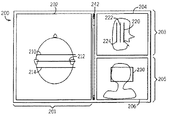
ここで図3を参照して説明すると、図2の2次元インターフェースに加えて、3次元グラフィック指定用インターフェース300を利用することもまた好ましい。グラフィック指定用インターフェース300では、アキシャル・ローカライザ画像202、サジタル・ローカライザ画像204及びコロナル・ローカライザ画像206が再びオペレータに対して表示される。しかしながら、グラフィック指定用インターフェース200がローカライザ画像202〜206の別々の2次元図を表示しているのに対し、グラフィック指定用インターフェース300はローカライザ画像202〜206の単一の3次元図を表示している。この図では、ローカライザ画像202、204及び206と指定した空間情報とが共通の観察領域301内に互いに対してオーバーラップした態様で表示される。指定用インターフェース300によって提供される図は3次元図と呼ばれ、その理由は、この図が実際には表示装置104のほぼ2次元の観察面上に示されるとしても、この図がオペレータにとって(例えば、図3が3次元の外観を持つのと同様にして)3次元に見えるからである。
【0026】
図3では、ローカライザ画像202〜206は明瞭にするために概略図で示されている。しかしながら、好ましい実施の形態では、患者の解剖学的構造の3次元断面を観察しているという印象をオペレータに与えるために実際のローカライザ画像がオペレータに対して表示される。指定した所定の画像を表すために、線212、214、216、222、224、226及び矩形230を表示するよりも、3次元画像のスラブが使用される。
【0027】
グラフィック指定用インターフェース300は、ローカライザ画像202〜206及び指定した空間情報の3次元図を提供することによって、グラフィック指定用インターフェース200を補足する。更に、指定用インターフェース300は、ローカライザ画像及び指定した空間情報を含む3次元図全体を回転させる入力をオペレータが供給できるようにする。これにより、オペレータは、3次元図が回転されるとき任意の透視方向から指定を観察して、特に二つの傾斜した指定の場合に、向きについて直感的に理解することができるようになる。
【0028】
指定用インターフェース300が指定用インターフェース200と組み合わせて使用されるので、オペレータがローカライザ画像202〜206上に空間情報を指定するために指定用インターフェース300を使用できるようにすることは特に必要ではなく、事実上、この指定能力を簡単化のために指定用インターフェース200のみによって提供することが好ましい。とは言え、代替の実施形態もまた確かに可能である。例えば、ローカライザ画像202〜206の各々に対して個別に指定用マークの位置を示す付加的な標識を設けることによって、オペレータが3次元の空間情報を正確に指定することができるように、指定用インターフェース300を使用することができる。この代わりに、明示的(expicit) 指定用インターフェースをグラフィック指定用インターフェース200の代わりに又はそれと組み合わせて使用して、オペレータがグラフィックによるよりも明示的に(例えば、キーボードを介して値を入力することによって)空間情報を指定することができるようにしてもよい。この場合、明示的指定用インターフェースを使用して指定された空間情報の可視化を行うためにグラフィック指定用インターフェース300が使用される。
【0029】
図4は、図2及び図3の指定用インターフェースに関連して使用される指定プロセスを示す。ステップ250において、MRIシステムは最初に複数のローカライザ画像を取得する。異なるローカライザ画像は、異なる透視方向(コロナル、アキシャル及びサジタル・ローカライザ画像を取得する場合には3つの透視方向)からの関心のある構造を示す。ステップ252において、スクロール・インターフェースによって、ステップ250で取得したローカライザ画像をスクロールして表示するように指定用インターフェース200及び/又は指定用インターフェース300を動作させるオペレータ入力が取得される。ステップ254において、システムは、グラフィック指定のために使用される選択したローカライザ画像202、204及び206を指定するオペレータ入力を取得する。
【0030】
ステップ256及び258において、ローカライザ画像202、204及び206の2次元図及び3次元図が、図2及び図3に関して前に説明したようにそれぞれ表示される。ステップ256及び258は2つの別々のステップとして示されているが、実際には、ステップ256及び258は同時に実行されるのが好ましい。
【0031】
ステップ260において、最初の一組のローカライザ画像が選択されて表示された後、指定を取得し、その結果生じる指定マークを表示する。ステップ260は次のように行うのが好ましい。先ず、オペレータ入力に応答して、表示されたローカライザ画像のうちの特定の1つを選択する。1つのローカライザ画像が選択されたとき、そのローカライザ画像に(1つ以上の指定用マークによって指示されるような)デフォルト指定が現れる(例えば、デフォルト指定を示す線がそのローカライザ画像上に自動的に現れる)。同時に、このデフォルト指定は残りのローカライザ画像にも表示される。このとき、オペレータは指定用マークを任意の所望の態様で操作することができるようになる。例えば、線が指定用マークとして使用されると仮定すると、オペレータは線をローカライザ画像上の新しい位置へ動かすと共に線の長さや向きを変えることができる。デフォルトによって、デフォルト指定の結果として非傾斜画像を生じるように線の向きが定められるが、オペレータは線を傾け又は回転させて、傾斜した向きを得ることができる。オペレータの立場から見ると、線の一部をクリックして該線を新しい向きへ回転させることにより、線の回転を行うことができる。しかし、当然のことであるが、実際には、指定用インターフェース200がオペレータ入力に応答して線を回転させる。典型的には、画像は一重なりの画像スライスとして取得されるので、指定用マークは好ましくは、一グループとして動かされ又は回転させられる。
【0032】
同時に、グラフィック指定用インターフェース300がローカライザ画像202〜206及び指定した空間情報の3次元図を提供する。その上、指定用インターフェース300は、オペレータがローカライザ画像及び指定した空間情報を含む3次元図の全体を回転させる入力を供給することを可能にする。
【0033】
ステップ262において、フォールバックを行う場合、フォールバック画像を選択し、且つ1つのローカライザ画像に関して行った指定が別の1つのローカライザ画像へフォールバックすることを指示するオペレータ入力が取得される。前に述べたように、この特徴により、オペレータは1つのローカライザ画像を使用して指定を行い、次いで他のローカライザ画像を使用して、所定の画像を中心に置くべき場所を指示することが可能になる。フォールバックを行わない場合は、勿論、このステップ262は飛び越される。
【0034】
最後に、ステップ264において、指定を取得した後、指定はMRIシステムの残りの部分へ供給される。該部分は指定を使用して、前に取得した指定にしたがって1つ以上の画像を取得する。好ましいインターフェース200及び300を用いた場合の利点は、異なる向きの複数のローカライザ画像が表示されるので、追加の画像を利用することにより幾つかの指定自由度が得られることである。オペレータは単一平面内で指定用マークを操作することに制限されず、したがって、非常に強力な指定用インターフェースが達成される。その上、所定の画像を多数の向きから観察する能力をオペレータに提供することにより、視覚化が改善される。図3のグラフィック指定用インターフェース300は、ローカライザ画像202〜206及び指定した空間情報の回転可能な3次元図を提供することによって、グラフィック指定用インターフェース200を補足する。
【0035】
ここで図5を参照すると、図5は指定相互参照動作モードにおける図2のグラフィック指定用インターフェースを示す。指定相互参照動作モードは、オペレータが現時点の指定を行いながら以前の指定を観察することを可能にする。これにより、以前の指定を参考として使用して、以前の指定を再生成すること、或いは新しい画像取得のために以前の指定からの空間情報の位置を僅かに調節することが可能になる。そこで、図5においては、第1の指定用の線401及び第2の指定用の線402が示されている。指定用の線401は以前の指定を表していて、破線で示されている。指定用の線402は、所定の画像が僅かに傾斜したコロナル画像になるように、指定用の線401に対して僅かに回転されている。したがって、オペレータが以前に取得した画像よりも僅かに異なる向きを持つ画像を取得したいとき、指定用の線401は所定の画像と以前に取得した画像との間の空間関係の表示をオペレータに提供する。これは、新しい画像を正確に指定するオペレータの能力を増大させる。
【0036】
現在好ましい本発明の実施の形態及び用途を図面に示し且つこれまで説明してきたが、これらの実施の形態が例として挙げたものであることを理解されたい。したがって、本発明は特定の実施の形態に限定されるものではなく、特許請求の範囲内に入る様々な変更を包含するものである。
【図面の簡単な説明】
【図1】本発明の好ましい実施の形態を用いるMRIシステムのブロック図である。
【図2】図1のMRIシステムに対する第1のグラフィック指定用インターフェースの略図であり、複数のローカライザ画像の別々の2次元図がオペレータに対して表示されている。
【図3】図1のMRIシステムに対する第2のグラフィック指定用インターフェースの略図であり、図2のローカライザ画像の3次元図が互いに対してオーバーラップした態様で表示されている。
【図4】図2及び図3の指定用インターフェースに関連して使用される指定プロセス図である。
【図5】指定相互参照動作モードにおける図2のグラフィック指定用インターフェースの動作を示す略図である。
【符号の説明】
100 オペレータ・コンソール
102 制御パネル
104 表示装置
200、300 グラフィック指定用インターフェース
201、203、205 観察領域
202、204、206 ローカライザ画像
210、212、214 線
220、224、226 線
242 スクロール・バー
301 共通の観察領域
401、402 指定用の線[0001]
BACKGROUND OF THE INVENTION
The field of the invention is imaging methods and systems. More specifically, the present invention relates to multi-planar graphics for imaging systems. Specified The present invention relates to an interface and method.
[0002]
BACKGROUND OF THE INVENTION
Imaging systems are typically used to allow an operator to obtain an image that shows the interior of a structure of interest. A common application of such imaging systems is medical imaging, and a common approach for implementing such imaging systems is magnetic resonance imaging, particularly with respect to medical imaging.
[0003]
When a subject such as a human tissue receives a uniform magnetic field (polarization magnetic field Bz), the individual magnetic moments of the spins in the tissue attempt to align with this polarization magnetic field, around which each unique Larmor is located. Precesses irregularly with frequency. A net magnetic moment Mz occurs in the direction of the polarization field, but its magnetic components occurring in an irregular orientation in an orthogonal or transverse plane (xy plane) cancel each other. Thus, when the subject (ie, tissue) receives a magnetic field (excitation magnetic field B1) having a frequency close to the Larmor frequency in the xy plane, the net aligned moment Mz rotates toward the xy plane. That is, it “tilts”, resulting in a net transverse magnetic moment M1 that rotates or turns at the Larmor frequency in the xy plane. The angle at which the net magnetic moment Mz tilts, and thus the magnitude of the net transverse magnetic moment M1, depends mainly on the length and magnitude of the applied excitation magnetic field. A signal is emitted by the excited spins, and after the excitation field is complete, this signal is received and processed to construct an image.
[0004]
When MRI (magnetic resonance imaging) is used to create an image, a technique for obtaining an MRI signal from a specific position in a subject is used. Typically, the region to be imaged is scanned with a series of MRI measurement cycles that are varied according to the particular localization method used. The resulting set of received MRI signals is digitized and processed to reconstruct the image using one of many well known reconstruction techniques. In order to perform the above-described scanning (scanning), naturally, it is indispensable to generate an MRI signal from a specific position in the subject. To do this, magnetic fields (Gx, Gy and Gz) having the same direction as the polarization magnetic field B0 and gradients along the respective x, y and z axes are used. By controlling the magnitude of these gradients during each MRI cycle, the spatial distribution of spin excitation can be controlled and the location of the resulting MRI signal can be identified.
[0005]
In order to acquire signals from the region of interest to the operator via the MRI system, the acquisition method to be performed must be entered, including entering parameters such as field of view, spacing and thickness along with the desired image orientation and position. First by operator Specified It is necessary to.
[0006]
graphic Specified In the (graphic prescription) method, the operator uses a graphic method. Specified It is a technique that makes it possible to perform. Typically a graphic Specified To perform the method, first obtain a plurality of localizer images for reference, and then the operator adds these localizer images to these localizer images such as dots, lines, boxes or other shapes Specified Mark for the desired and Specified The mark can be manipulated until is achieved. The operator operates in an efficient manner so that the operator Specified Can make Specified It is desirable to provide a user interface. However, when creating an image inside the 3D structure, the operator Specified The orientation of the spatial information two In the case of tilt, it is often difficult to visualize. Even if multiple localizer images are displayed, Specified The three-dimensional orientation of spatial information is not always self-evident and therefore inaccurate Specified Often occur.
[0007]
Summary of the Invention
In an exemplary embodiment of the present invention, graphics from the operator of the imaging device Specified Is provided, the method comprising displaying a two-dimensional view of the first and second localizer images and displaying a three-dimensional view of the first and second localizer images. . The first and second two-dimensional views of the first and second localizer images are graphical Specified Displayed in the first and second observation areas of the interface. The three-dimensional view of the first and second localizer images is a graphic Specified The first and second localizer images are shown in an overlapping manner with respect to each other in one observation region of the interface for the display.
[0008]
A preferred embodiment of the present invention is a graphic Specified Greatly enhance the operator's ability to do exactly. Operators can obtain spatial information in multiple separate localizer images. Specified Provides the ability to be immediately observed, and the displayed localizer image and Specified A three-dimensional view is provided that displays the spatial information that has been rendered in three dimensions relative to each other. For the operator Specified Give a better visual understanding of the spatial information Specified More accurate by providing a method Specified Is achieved.
[0009]
BEST MODE FOR CARRYING OUT THE INVENTION
FIG. 1 shows the major components of a preferred MRI system that incorporates a preferred embodiment of the present invention. The operation of this system is controlled from an
[0010]
The
[0011]
The gradient waveform generated by the pulse generator module 121 is applied to a
[0012]
The MRI signal detected by the RF coil 152 is digitized by the
[0013]
2 and 3, first and second graphics according to a preferred embodiment of the present invention.
[0014]
First, referring to FIG.
[0015]
The number and type of localizer images to be displayed can be selected by the operator. Preferably, a set of coronal localizer images, a set of sagittal localizer images, and a set of axial localizer images are acquired and arranged along a common orthogonal axis within each set. Acquire 3 to 5 images. The operator uses the
[0016]
Using the
[0017]
For example, referring to the
[0018]
Referring to the
[0019]
Referring to the
[0020]
Since the predetermined image is a coronal image in the illustrated example, the
[0021]
As described above, in the illustrated embodiment, the
[0022]
On one localizer image Specified The spatial information is displayed simultaneously on all affected localizer images. Therefore, Specified If the position and orientation of the spatial information is changed, this change is immediately displayed in the remaining affected localizer images. For example, if the observation range is changed in one direction in the
[0023]
further, Specified The
[0024]
The scroll interface of FIG. 2 also preferably implements a fallback feature. In the fallback feature, the operator uses one localizer image in a series of localizer images. Specified And then the Specified Can fall back to any other localizer image in the series of localizer images. For example, a series of coronal localizer images can be used to create a sagittal image of a patient's shoulder. Specified When doing this, the following sequence of events can occur: Initially, an operator input for selecting a first coronal localizer image acquired from a first position in the front / rear direction is acquired. This first localizer image is selected based on the fact that a particular region of the anatomy can be seen more clearly in the first localizer image than in other localizer images. The first localizer image is then used to Specified An operator input is acquired. An operator input is then acquired that selects a second coronal localizer image acquired from a second position in the front / rear direction. This second localizer image is selected based on the operator's desire to center the predetermined sagittal image at the second position (front / rear direction). Finally, it was done on the first localizer image Specified An operator input is obtained that indicates that should fall back to the second localizer image. This is because the operator uses the first localizer image in the sequence of localizer images. Specified And then the second localizer image is used to indicate where the predetermined image should be centered. This is particularly useful when all localizer images are acquired along a single common axis.
[0025]
Referring now to FIG. 3, in addition to the two-dimensional interface of FIG. Specified It is also preferable to use the
[0026]
In FIG. 3, the localizer images 202-206 are shown in schematic form for clarity. However, in the preferred embodiment, the actual localizer image is displayed to the operator to give the operator the impression that he is observing a three-dimensional section of the patient's anatomy. Specified Rather than displaying
[0027]
graphic
[0028]
[0029]
4 is the same as FIG. 2 and FIG. Specified Used in connection with the interface Specified Indicates the process. In
[0030]
In
[0031]
In
[0032]
Graphic at the same time Specified
[0033]
In
[0034]
Finally, in
[0035]
Referring now to FIG. 5, FIG. Specified Figure 2 in cross-reference mode of operation Specified The interface is shown. Specified The cross-reference mode of operation allows the operator to Specified While doing the previous Specified Makes it possible to observe. This allows the previous Specified Using the previous as a reference Specified To recreate the previous or new image acquisition Specified It is possible to slightly adjust the position of the spatial information from. Therefore, in FIG.
[0036]
While the presently preferred embodiments and applications of the present invention have been shown in the drawings and described above, it should be understood that these embodiments have been given by way of example. Accordingly, the invention is not limited to the specific embodiments, but encompasses various modifications that fall within the scope of the claims.
[Brief description of the drawings]
FIG. 1 is a block diagram of an MRI system using a preferred embodiment of the present invention.
FIG. 2 is a first graphic for the MRI system of FIG. Specified FIG. 2 is a schematic diagram of a user interface, and separate two-dimensional views of a plurality of localizer images are displayed to an operator.
3 is a second graphic for the MRI system of FIG. Specified FIG. 2 is a schematic diagram of a local interface, and the three-dimensional view of the localizer image of FIG. 2 is displayed in an overlapping manner with respect to each other.
4 is a view of FIG. 2 and FIG. Specified Used in connection with the interface Specified It is a process diagram.
[Figure 5] Specified Figure 2 in cross-reference mode of operation Specified FIG.
[Explanation of symbols]
100 operator console
102 Control panel
104 Display device
200, 300 graphics Specified Interface
201, 203, 205 Observation area
202, 204, 206 Localizer image
210, 212, 214 lines
220, 224, 226 lines
242 Scroll bar
301 Common observation area
401, 402 Specified Line for
Claims (10)
所定の画像を取得しようとする所望の位置及び所望の向きを指示する指定用マーク(210、212、214、220、222、224)が、上記第1のローカライザ画像(202、204)の上記第1の2次元図に表示され、また、上記所定の画像を取得しようとする上記所望の位置及び上記所望の向きを指示する別の指定用マークが、上記第1及び第2のローカライザ画像の3次元図に表示され、
前記第2のインターフェース(300)は、前記別の指定用マークの位置及び向きをユーザが変更することを可能にし、
第1のインターフェース(200)は、変更された前記別の指定用マークの位置に対応する2次元図であって、予め格納された画像データに基づいて生成され、第1のローカライザ画像に中心あわせされた2次元図を新たな第2のローカライザ画像として表示することを特徴とするグラフィック指定用インターフェース。A first interface (200) comprising a first two-dimensional view of a first localizer image (202, 204, 206) and a second two-dimensional view of a second localizer image (202, 204, 206); A second interface (300) including a three-dimensional view of the first and second localizer images (202, 204, 206), wherein the three-dimensional view includes the first and second localizer images (202). , 204, 206) in a manner overlapping with each other, a second interface (300),
A designation mark (210, 212, 214, 220, 222, 224) that indicates a desired position and a desired orientation from which a predetermined image is to be acquired is displayed on the first localizer image (202, 204). Another designation mark that is displayed on the two-dimensional diagram of 1 and that indicates the desired position and the desired orientation from which the predetermined image is to be obtained is displayed in 3 of the first and second localizer images. Displayed in the dimensional diagram,
The second interface (300) allows a user to change the position and orientation of the other designation mark,
First interface (200) is a two-dimensional view corresponding to the changed position of said another specified marks are generated on the basis of the image data stored in advance, together centered first localizer image A graphic designating interface, wherein the two-dimensional figure displayed is displayed as a new second localizer image.
第1のローカライザ画像(202、204、206)の第1の2次元図及び第2のローカライザ画像(202、204、206)の第2の2次元図を表示するステップ(256)であって、上記第1及び第2のローカライザ画像(202、204、206)の上記第1及び第2の2次元図が、グラフィック指定用インターフェース(200、300)の第1及び第2の観察領域(201、203、205)に表示されるようにするステップ(256)と、上記第1及び第2のローカライザ画像(202、204、206)の3次元図を表示するステップ(258)であって、上記3次元図は、上記グラフィック指定用インターフェース(200、300)の共通の観察領域(301)に上記第1及び第2のローカライザ画像(202、204、206)を互いに対してオーバーラップした態様で示している、ステップ(258)と、上記第1及び第2のローカライザ画像(202、204、206)の1つにおいて空間情報を指定し且つ所定の画像を生成しようとする所望の位置及び所望の向きを指示するオペレータ入力を取得するステップ(260)と、上記第1及び第2のローカライザ画像(202、204、206)の上記第1及び第2の2次元図と上記第1及び第2のローカライザ画像(202、204、206)の3次元図とに上記指定した空間情報を表示するステップ(260)であって、上記所定の画像と少なくとも1つの上記ローカライザ画像(202、204、206)との交差部を指示する少なくとも1つの指定用マーク(210、212、214、220、222、224)を表示し、且つ上記少なくとも1つのローカライザ画像(202、204、206)上への上記所定の画像の投影を指示する少なくとも1つの指定用マーク(230)を表示することを含んでいる、該表示するステップ(260)と、
上記所定の画像を磁気共鳴イメージング・システムの情報処理装置により生成するステップ(264)であって、該取得した所定の画像が、上記指定した空間情報によって決定された上記関心のある構造の位置を描画し且つ上記指定した空間情報によって決定された向きから前記磁気共鳴イメージング・システムが取得し、予め格納された画像データを処理して上記位置を描画している、該生成するステップ(264)と、を有し、
所定の画像を取得しようとする所望の位置及び所望の向きを指示する指定用マーク(210、212、214、220、222、224)が、上記第1のローカライザ画像(202、204)の上記第1の2次元図に表示され、また、上記所定の画像を取得しようとする上記所望の位置及び上記所望の向きを指示する別の指定用マークが、上記第1及び第2のローカライザ画像の3次元図に表示され、
前記第2のインターフェース(300)は、前記別の指定用マークの位置及び向きをユーザが変更することを可能にし、
第1のインターフェース(200)は、変更された前記別の指定用マークの位置に対応する2次元図であって、予め格納された前記画像データに基づいて生成され、第1のローカライザ画像に中心あわせされた2次元図を新たな第2のローカライザ画像として表示する当該方法。A method for obtaining a graphic designation from an operator of a magnetic resonance imaging apparatus,
Displaying (256) a first two-dimensional view of the first localizer image (202, 204, 206) and a second two-dimensional view of the second localizer image (202, 204, 206), The first and second two-dimensional views of the first and second localizer images (202, 204, 206) represent the first and second observation areas (201, 201) of the graphic designating interface (200, 300). 203 (205), and a step (258) for displaying a three-dimensional view of the first and second localizer images (202, 204, 206). The dimensional diagram shows the first and second localizer images (202, 204) in the common observation area (301) of the graphic designation interface (200, 300). 206) showing the spatial information in one of the step (258) and the first and second localizer images (202, 204, 206) shown in an overlapping manner with respect to each other. Obtaining an operator input indicating a desired position and desired orientation to be generated, and the first and second of the first and second localizer images (202, 204, 206) Displaying the designated spatial information in a two-dimensional view and a three-dimensional view of the first and second localizer images (202, 204, 206), wherein the predetermined image and at least one of the predetermined images are displayed; At least one designation mark (210, 212, 214, 220, indicating an intersection with the localizer image (202, 204, 206); 22 and 224) and displaying at least one designation mark (230) indicating the projection of the predetermined image onto the at least one localizer image (202, 204, 206). The displaying step (260);
A step (264) of generating the predetermined image by an information processing apparatus of a magnetic resonance imaging system, wherein the acquired predetermined image indicates a position of the structure of interest determined by the designated spatial information. The step of generating (264), wherein the magnetic resonance imaging system draws and processes the pre-stored image data to draw the position by drawing and orientation determined by the designated spatial information; Have
A designation mark (210, 212, 214, 220, 222, 224) that indicates a desired position and a desired orientation from which a predetermined image is to be acquired is displayed on the first localizer image (202, 204). Another designation mark that is displayed on the two-dimensional diagram of 1 and that indicates the desired position and the desired orientation from which the predetermined image is to be obtained is displayed in 3 of the first and second localizer images. Displayed in the dimensional diagram,
The second interface (300) allows a user to change the position and orientation of the other designation mark,
First interface (200) is a two-dimensional view corresponding to the changed position of said another specified marks are generated on the basis of the image data stored in advance, central to the first localizer image The said method of displaying the put together two-dimensional figure as a new 2nd localizer image.
Applications Claiming Priority (2)
| Application Number | Priority Date | Filing Date | Title |
|---|---|---|---|
| US09/748929 | 2000-12-27 | ||
| US09/748,929 US6844884B2 (en) | 2000-12-27 | 2000-12-27 | Multi-plane graphic prescription interface and method |
Publications (3)
| Publication Number | Publication Date |
|---|---|
| JP2002315734A JP2002315734A (en) | 2002-10-29 |
| JP2002315734A5 JP2002315734A5 (en) | 2005-08-04 |
| JP4660040B2 true JP4660040B2 (en) | 2011-03-30 |
Family
ID=25011504
Family Applications (1)
| Application Number | Title | Priority Date | Filing Date |
|---|---|---|---|
| JP2001393062A Expired - Fee Related JP4660040B2 (en) | 2000-12-27 | 2001-12-26 | Interface and method for specifying multi-plane graphics |
Country Status (3)
| Country | Link |
|---|---|
| US (1) | US6844884B2 (en) |
| EP (1) | EP1220154A3 (en) |
| JP (1) | JP4660040B2 (en) |
Families Citing this family (38)
| Publication number | Priority date | Publication date | Assignee | Title |
|---|---|---|---|---|
| CA2314794A1 (en) * | 2000-08-01 | 2002-02-01 | Dimitre Hristov | Apparatus for lesion or organ localization |
| FR2824164B1 (en) * | 2001-04-26 | 2003-08-15 | Ge Med Sys Global Tech Co Llc | MEDICAL IMAGING SYSTEM WITH THREE-DIMENSIONAL REPRESENTATION |
| DE10154799B4 (en) * | 2001-11-08 | 2005-08-18 | Siemens Ag | Medical diagnostic imaging apparatus and method for operating a magnetic resonance device in medicine |
| US7123008B1 (en) * | 2002-04-19 | 2006-10-17 | Fonar Corporation | Positional magnetic resonance imaging |
| US8036730B1 (en) | 2002-04-19 | 2011-10-11 | Fonar Corporation | Temporal magnetic resonance imaging |
| US7519541B2 (en) * | 2003-01-29 | 2009-04-14 | Cerner Innovation, Inc. | System and method in a computer system for managing a number of attachments associated with a patient |
| US7668285B2 (en) * | 2004-02-16 | 2010-02-23 | Kabushiki Kaisha Toshiba | X-ray computed tomographic apparatus and image processing apparatus |
| DE102004023849B4 (en) * | 2004-05-13 | 2013-09-26 | Siemens Aktiengesellschaft | Medical examination device for taking slice images of an examination object, in particular a magnetic resonance device |
| US7672705B2 (en) * | 2004-07-19 | 2010-03-02 | Resonant Medical, Inc. | Weighted surface-to-surface mapping |
| US8000442B2 (en) * | 2004-07-20 | 2011-08-16 | Resonant Medical, Inc. | Calibrating imaging devices |
| US7729744B2 (en) * | 2004-07-20 | 2010-06-01 | Resonant Medical, Inc. | Verifying lesion characteristics using beam shapes |
| DE102004043058A1 (en) * | 2004-09-06 | 2006-04-06 | Siemens Ag | Method for the determination of excellent coronal and sagittal planes for the subsequent acquisition of new magnetic resonance slice images or the representation of magnetic resonance slice images from an already existing image data set of a shoulder joint |
| DE102004043263B4 (en) * | 2004-09-07 | 2007-06-06 | Siemens Ag | Method for generating localiser slice images of a patient's examination volume and associated magnetic resonance system |
| WO2006032134A2 (en) * | 2004-09-20 | 2006-03-30 | Resonant Medical Inc. | Radiotherapy treatment monitoring using ultrasound |
| DE102005001325B4 (en) * | 2005-01-11 | 2009-04-09 | Siemens Ag | Method for aligning a graphic object on an overview image of an object |
| EP1940515A4 (en) * | 2005-09-06 | 2010-05-26 | Resonant Medical Inc | System and method for patient setup for radiotherapy treatment |
| US8199168B2 (en) * | 2005-11-15 | 2012-06-12 | General Electric Company | System and method for 3D graphical prescription of a medical imaging volume |
| US8929621B2 (en) * | 2005-12-20 | 2015-01-06 | Elekta, Ltd. | Methods and systems for segmentation and surface matching |
| JP5433130B2 (en) * | 2006-07-13 | 2014-03-05 | 株式会社東芝 | Magnetic resonance imaging system |
| US9451928B2 (en) * | 2006-09-13 | 2016-09-27 | Elekta Ltd. | Incorporating internal anatomy in clinical radiotherapy setups |
| US20080119723A1 (en) * | 2006-11-22 | 2008-05-22 | Rainer Wegenkittl | Localizer Display System and Method |
| US8249317B2 (en) * | 2007-07-20 | 2012-08-21 | Eleckta Ltd. | Methods and systems for compensating for changes in anatomy of radiotherapy patients |
| US10531858B2 (en) | 2007-07-20 | 2020-01-14 | Elekta, LTD | Methods and systems for guiding the acquisition of ultrasound images |
| US20090027380A1 (en) * | 2007-07-23 | 2009-01-29 | Vivek Rajan | 3-D visualization |
| US8135198B2 (en) * | 2007-08-08 | 2012-03-13 | Resonant Medical, Inc. | Systems and methods for constructing images |
| JP5431670B2 (en) * | 2007-12-28 | 2014-03-05 | ジーイー・メディカル・システムズ・グローバル・テクノロジー・カンパニー・エルエルシー | Image display apparatus, display method, and MRI apparatus |
| US8189738B2 (en) * | 2008-06-02 | 2012-05-29 | Elekta Ltd. | Methods and systems for guiding clinical radiotherapy setups |
| JP5426219B2 (en) * | 2009-04-13 | 2014-02-26 | 株式会社日立メディコ | Magnetic resonance imaging system |
| DE102009020000B4 (en) * | 2009-05-05 | 2020-03-12 | Siemens Healthcare Gmbh | Method and control device for operating a magnetic resonance system |
| US10542962B2 (en) * | 2009-07-10 | 2020-01-28 | Elekta, LTD | Adaptive radiotherapy treatment using ultrasound |
| JP5378149B2 (en) * | 2009-10-22 | 2013-12-25 | 株式会社東芝 | MRI apparatus and imaging area setting control program |
| US9248316B2 (en) | 2010-01-12 | 2016-02-02 | Elekta Ltd. | Feature tracking using ultrasound |
| US20110172526A1 (en) | 2010-01-12 | 2011-07-14 | Martin Lachaine | Feature Tracking Using Ultrasound |
| CN102908142B (en) * | 2011-08-04 | 2015-05-13 | 上海联影医疗科技有限公司 | Three-dimensional graphical lamina positioning method in magnetic resonance imaging and magnetic resonance imaging system |
| JP6061497B2 (en) * | 2012-05-31 | 2017-01-18 | ジーイー・メディカル・システムズ・グローバル・テクノロジー・カンパニー・エルエルシー | Medical device, display device, and program |
| JP5702828B2 (en) * | 2013-05-20 | 2015-04-15 | 株式会社東芝 | Magnetic resonance imaging system |
| JP6397904B2 (en) * | 2013-06-07 | 2018-09-26 | コーニンクレッカ フィリップス エヌ ヴェKoninklijke Philips N.V. | Visual prescan patient information for magnetic resonance protocols |
| KR101659577B1 (en) * | 2014-08-14 | 2016-09-23 | 삼성전자주식회사 | Magnetic resonance imaging apparatus and generating method for magnetic resonance image thereof |
Citations (6)
| Publication number | Priority date | Publication date | Assignee | Title |
|---|---|---|---|---|
| JPS63186628A (en) * | 1987-01-28 | 1988-08-02 | 株式会社東芝 | Three-dimensional image processing apparatus |
| JPH04158855A (en) * | 1990-10-24 | 1992-06-01 | Aloka Co Ltd | Ultrasonic image display device |
| JPH04332544A (en) * | 1990-11-22 | 1992-11-19 | Advanced Technol Lab Inc | Acoustical hold gram system |
| JPH06189935A (en) * | 1992-09-16 | 1994-07-12 | Toshiba Medical Eng Co Ltd | Positioning scan method and magnetic resonance imaging device |
| JPH09135815A (en) * | 1995-11-17 | 1997-05-27 | Toshiba Medical Eng Co Ltd | Medical image display device |
| JP2000051202A (en) * | 1998-08-14 | 2000-02-22 | Ge Yokogawa Medical Systems Ltd | Image displaying method and image displaying device |
Family Cites Families (7)
| Publication number | Priority date | Publication date | Assignee | Title |
|---|---|---|---|---|
| JP2614726B2 (en) * | 1987-09-07 | 1997-05-28 | 株式会社日立メデイコ | Nuclear magnetic resonance imaging equipment |
| US6484048B1 (en) * | 1998-10-21 | 2002-11-19 | Kabushiki Kaisha Toshiba | Real-time interactive three-dimensional locating and displaying system |
| US6108573A (en) * | 1998-11-25 | 2000-08-22 | General Electric Co. | Real-time MR section cross-reference on replaceable MR localizer images |
| US6396266B1 (en) * | 1998-11-25 | 2002-05-28 | General Electric Company | MR imaging system with interactive MR geometry prescription control |
| DE19854905C2 (en) * | 1998-11-27 | 2002-08-14 | Siemens Ag | Method for displaying the tip of a medical instrument located in the body of a patient |
| US6379302B1 (en) * | 1999-10-28 | 2002-04-30 | Surgical Navigation Technologies Inc. | Navigation information overlay onto ultrasound imagery |
| US6563941B1 (en) * | 1999-12-14 | 2003-05-13 | Siemens Corporate Research, Inc. | Model-based registration of cardiac CTA and MR acquisitions |
-
2000
- 2000-12-27 US US09/748,929 patent/US6844884B2/en not_active Expired - Fee Related
-
2001
- 2001-12-20 EP EP01310701A patent/EP1220154A3/en not_active Ceased
- 2001-12-26 JP JP2001393062A patent/JP4660040B2/en not_active Expired - Fee Related
Patent Citations (6)
| Publication number | Priority date | Publication date | Assignee | Title |
|---|---|---|---|---|
| JPS63186628A (en) * | 1987-01-28 | 1988-08-02 | 株式会社東芝 | Three-dimensional image processing apparatus |
| JPH04158855A (en) * | 1990-10-24 | 1992-06-01 | Aloka Co Ltd | Ultrasonic image display device |
| JPH04332544A (en) * | 1990-11-22 | 1992-11-19 | Advanced Technol Lab Inc | Acoustical hold gram system |
| JPH06189935A (en) * | 1992-09-16 | 1994-07-12 | Toshiba Medical Eng Co Ltd | Positioning scan method and magnetic resonance imaging device |
| JPH09135815A (en) * | 1995-11-17 | 1997-05-27 | Toshiba Medical Eng Co Ltd | Medical image display device |
| JP2000051202A (en) * | 1998-08-14 | 2000-02-22 | Ge Yokogawa Medical Systems Ltd | Image displaying method and image displaying device |
Also Published As
| Publication number | Publication date |
|---|---|
| EP1220154A2 (en) | 2002-07-03 |
| EP1220154A3 (en) | 2004-04-14 |
| US20020082494A1 (en) | 2002-06-27 |
| US6844884B2 (en) | 2005-01-18 |
| JP2002315734A (en) | 2002-10-29 |
Similar Documents
| Publication | Publication Date | Title |
|---|---|---|
| JP4660040B2 (en) | Interface and method for specifying multi-plane graphics | |
| US6108573A (en) | Real-time MR section cross-reference on replaceable MR localizer images | |
| JP4129375B2 (en) | Medical image diagnostic apparatus and image region designation support method | |
| EP1220153B1 (en) | Methods and apparatus for generating a scout image | |
| US6275721B1 (en) | Interactive MRI scan control using an in-bore scan control device | |
| US6484048B1 (en) | Real-time interactive three-dimensional locating and displaying system | |
| US6049622A (en) | Graphic navigational guides for accurate image orientation and navigation | |
| US7920911B2 (en) | Interventional MR imaging with detection and display of device position | |
| US5584293A (en) | Time-line imaging-plane prescription for MRI | |
| US20060152220A1 (en) | Coil element selection method and magnetic resonance imaging apparatus | |
| US6275035B1 (en) | Method for using three points to define a 2D MR imaging section | |
| US6757417B2 (en) | Method and apparatus for defining a three-dimensional imaging section | |
| EP1052522B1 (en) | Method and system for providing an intensity projection of a non-planar image | |
| US5708359A (en) | Interactive, stereoscopic magnetic resonance imaging system | |
| JP3809105B2 (en) | Magnetic resonance imaging system | |
| JP2000189400A (en) | Three-dimensional positioning display device | |
| JP2010051615A (en) | Magnetic resonance imaging apparatus | |
| JP2009045274A (en) | Magnetic resonance imaging apparatus | |
| JP4785307B2 (en) | Puncture aid | |
| US11555874B2 (en) | System and method for real-time magnetic resonance imaging data visualization in three or four dimensions | |
| JP5426219B2 (en) | Magnetic resonance imaging system | |
| JP5309379B2 (en) | Medical imaging device | |
| JP2002034949A (en) | Three-dimensional position determining display device and magnetic resonance imaging apparatus | |
| JP4429867B2 (en) | Magnetic resonance imaging system | |
| JP2002209871A (en) | Magnetic resonance imaging instrument |
Legal Events
| Date | Code | Title | Description |
|---|---|---|---|
| A521 | Request for written amendment filed |
Free format text: JAPANESE INTERMEDIATE CODE: A523 Effective date: 20041224 |
|
| A621 | Written request for application examination |
Free format text: JAPANESE INTERMEDIATE CODE: A621 Effective date: 20041224 |
|
| A977 | Report on retrieval |
Free format text: JAPANESE INTERMEDIATE CODE: A971007 Effective date: 20061117 |
|
| A131 | Notification of reasons for refusal |
Free format text: JAPANESE INTERMEDIATE CODE: A131 Effective date: 20080527 |
|
| A521 | Request for written amendment filed |
Free format text: JAPANESE INTERMEDIATE CODE: A523 Effective date: 20080702 |
|
| A02 | Decision of refusal |
Free format text: JAPANESE INTERMEDIATE CODE: A02 Effective date: 20090303 |
|
| A521 | Request for written amendment filed |
Free format text: JAPANESE INTERMEDIATE CODE: A523 Effective date: 20090515 |
|
| A911 | Transfer to examiner for re-examination before appeal (zenchi) |
Free format text: JAPANESE INTERMEDIATE CODE: A911 Effective date: 20090521 |
|
| A912 | Re-examination (zenchi) completed and case transferred to appeal board |
Free format text: JAPANESE INTERMEDIATE CODE: A912 Effective date: 20091225 |
|
| RD02 | Notification of acceptance of power of attorney |
Free format text: JAPANESE INTERMEDIATE CODE: A7422 Effective date: 20100714 |
|
| RD04 | Notification of resignation of power of attorney |
Free format text: JAPANESE INTERMEDIATE CODE: A7424 Effective date: 20100714 |
|
| A521 | Request for written amendment filed |
Free format text: JAPANESE INTERMEDIATE CODE: A523 Effective date: 20101102 |
|
| A01 | Written decision to grant a patent or to grant a registration (utility model) |
Free format text: JAPANESE INTERMEDIATE CODE: A01 |
|
| A61 | First payment of annual fees (during grant procedure) |
Free format text: JAPANESE INTERMEDIATE CODE: A61 Effective date: 20101228 |
|
| FPAY | Renewal fee payment (event date is renewal date of database) |
Free format text: PAYMENT UNTIL: 20140107 Year of fee payment: 3 |
|
| R150 | Certificate of patent or registration of utility model |
Free format text: JAPANESE INTERMEDIATE CODE: R150 |
|
| LAPS | Cancellation because of no payment of annual fees |