JP5378149B2 - MRI apparatus and imaging area setting control program - Google Patents
MRI apparatus and imaging area setting control program Download PDFInfo
- Publication number
- JP5378149B2 JP5378149B2 JP2009243458A JP2009243458A JP5378149B2 JP 5378149 B2 JP5378149 B2 JP 5378149B2 JP 2009243458 A JP2009243458 A JP 2009243458A JP 2009243458 A JP2009243458 A JP 2009243458A JP 5378149 B2 JP5378149 B2 JP 5378149B2
- Authority
- JP
- Japan
- Prior art keywords
- image data
- imaging
- section
- magnetic field
- positioning image
- Prior art date
- Legal status (The legal status is an assumption and is not a legal conclusion. Google has not performed a legal analysis and makes no representation as to the accuracy of the status listed.)
- Expired - Fee Related
Links
Images


Description
本発明は、MRI装置及び撮影領域設定用制御プログラムに係り、特に、パイロット撮影モードによって得られた画像データに基づいて本撮影モードにおける画像データの撮影領域や撮影断面を設定するMRI装置及び撮影領域設定用制御プログラムに関する。 The present invention relates to an MRI apparatus and an imaging area setting control program, and in particular, an MRI apparatus and an imaging area for setting an imaging area and an imaging section of image data in the imaging mode based on image data obtained in a pilot imaging mode. The present invention relates to a setting control program.
磁気共鳴イメージング法(MRI)は、強力な静磁場中に置かれた被検体組織の原子核スピンを、そのラーモア周波数をもつ高周波信号(RFパルス)で励起し、この励起に伴って発生する磁気共鳴信号(MR信号)を再構成処理して画像データを生成するイメージング法である。 Magnetic resonance imaging (MRI) excites nuclear spins in a subject tissue placed in a strong static magnetic field with a high-frequency signal (RF pulse) having the Larmor frequency, and magnetic resonance generated by the excitation. This is an imaging method for generating image data by reconstructing a signal (MR signal).
MRI装置は、生体内から検出されるMR信号に基づいて画像データを生成する画像診断装置であり、解剖学的診断情報のみならず機能診断情報や生化学情報等多くの診断情報を得ることができるため、今日の画像診断の分野では不可欠なものとなっている。 An MRI apparatus is an image diagnostic apparatus that generates image data based on MR signals detected from within a living body, and can obtain a lot of diagnostic information such as functional diagnostic information and biochemical information as well as anatomical diagnostic information. As a result, it is indispensable in the field of diagnostic imaging today.
このようなMRI装置では、被検体の生体組織から発生するMR信号に対して位置情報を与えるために強力な静磁場と互いに直交する3つの傾斜磁場が前記被検体に対して印加されるが、静磁場を発生する主磁石及び静磁場電源や傾斜磁場を発生する傾斜磁場コイル及び傾斜磁場電源の性能限界により被検体に印加される静磁場や傾斜磁場に不均一性や非直線性等の磁場誤差が発生する。そして、このような静磁場や傾斜磁場を用いたMRI撮影によって得られる画像データは上述の磁場誤差に起因した画像歪みを有している。 In such an MRI apparatus, a strong static magnetic field and three gradient magnetic fields orthogonal to each other are applied to the subject in order to give positional information to MR signals generated from the biological tissue of the subject. Magnetic field such as inhomogeneity and non-linearity in static magnetic field and gradient magnetic field applied to subject due to performance limitations of main magnet and static magnetic field power source and gradient magnetic field coil and gradient magnetic field power source that generate static magnetic field An error occurs. And the image data obtained by MRI imaging using such a static magnetic field or a gradient magnetic field has the image distortion resulting from the above-mentioned magnetic field error.
このような磁場誤差に起因した画像歪みを低減するために、静磁場や傾斜磁場の強度分布データをシミュレーションや測定によって予め収集し、当該MRI撮影によって生成された画像データの画素を上述の強度分布データに基づいて補正することにより画像歪みが低減された良質な画像データを収集する方法が提案されている(例えば、特許文献1参照。)。 In order to reduce the image distortion due to such a magnetic field error, intensity distribution data of a static magnetic field and a gradient magnetic field is collected in advance by simulation and measurement, and the pixel of the image data generated by the MRI imaging is used as the intensity distribution described above. There has been proposed a method of collecting high-quality image data in which image distortion is reduced by performing correction based on the data (see, for example, Patent Document 1).
一方、MRI撮影では、本撮影モードにて生成される画像データ(以下では、診断用画像データと呼ぶ。)の撮影断面や撮影領域の設定を目的とした画像データ(以下では、位置決め用画像データと呼ぶ。)の収集が本撮影モードに先行するパイロット撮影モードにおいて行なわれる。例えば、被検体の体軸方向に垂直なアキシャル断面における画像データを本撮影モードの診断用画像データとして収集する場合、本撮影モードに先行して行なわれるパイロット撮影モードにて体軸方向に平行なサジタル断面あるいはコロナル断面の画像データが撮影断面を設定するための位置決め用画像データとして収集され、アキシャル断面の画像データが撮影領域を設定するための位置決め用画像データとして収集される。 On the other hand, in MRI imaging, image data (hereinafter referred to as positioning image data) for the purpose of setting the imaging section and imaging area of image data (hereinafter referred to as diagnostic image data) generated in the main imaging mode. Is collected in the pilot shooting mode preceding the main shooting mode. For example, when collecting image data on an axial section perpendicular to the body axis direction of the subject as diagnostic image data in the main imaging mode, the image data is parallel to the body axis direction in the pilot imaging mode performed prior to the main imaging mode. Image data of a sagittal section or coronal section is collected as positioning image data for setting an imaging section, and image data of an axial section is collected as positioning image data for setting an imaging area.
しかしながら、磁場誤差に起因した画像歪みが特許文献1に記載された方法等によって補正された位置決め用画像データを用いて本撮影モードの撮影断面を設定する場合、撮影断面の位置に対応するRFパルスの中心周波数と前記撮影断面が設定された生体組織が発生するMR信号の磁気共鳴周波数は一致していないため、被検体に対する撮影断面の設定を正確に行なうことができない。このため、パイロット撮影モードの位置決め用画像データを用いて本撮影モードの撮影断面を設定する場合、磁場誤差に起因した画像歪みが補正される前の位置決め用画像データに基づいて本撮影モードの撮影断面を設定する方法が提案されている(例えば、特許文献2参照。)。 However, when the imaging section in the main imaging mode is set using the positioning image data in which the image distortion due to the magnetic field error is corrected by the method described in Patent Document 1, the RF pulse corresponding to the position of the imaging section Since the center frequency of MR and the magnetic resonance frequency of the MR signal generated by the biological tissue in which the imaging section is set do not match, it is not possible to accurately set the imaging section for the subject. For this reason, when setting the imaging section in the main imaging mode using the positioning image data in the pilot imaging mode, the imaging in the main imaging mode is performed based on the positioning image data before the image distortion due to the magnetic field error is corrected. A method of setting a cross section has been proposed (see, for example, Patent Document 2).
上述のように本撮影モードの診断用画像データを収集する際には上述の撮影断面の他に撮影領域をパイロット撮影モードの位置決め用画像データに基づいて設定する必要があり、例えば、当該被検体の体軸方向に略平行なサジタル断面の画像データを本撮影モードの診断用画像データとして収集する場合、パイロット撮影モードにおいて収集されたサジタル断面における画像歪み補正前の位置決め用画像データを用いて撮影領域を設定する従来の方法では、前記位置決め用画像データが有する画像歪みにより撮影領域を正確に設定することができないという問題点を有していた。 As described above, when collecting diagnostic image data in the main imaging mode, it is necessary to set an imaging region in addition to the above-described imaging cross section based on positioning image data in the pilot imaging mode. When image data of a sagittal section approximately parallel to the body axis direction is collected as diagnostic image data in the main imaging mode, imaging is performed using image data for positioning before image distortion correction in the sagittal section acquired in the pilot imaging mode. The conventional method for setting the area has a problem that the imaging area cannot be set accurately due to the image distortion of the positioning image data.
本発明は、上述の問題点に鑑みてなされたものであり、その目的は、磁場の不均一性や非直線性等に起因して発生した画像歪みが補正される前の位置決め用画像データを用いて診断用画像データの撮影断面を設定し、画像歪みが補正された位置決め用画像データを用いて診断用画像データの撮影領域を設定することにより、所望の撮影領域や撮影断面を高い精度で設定することが可能なMRI装置及び撮影領域設定用制御プログラムを提供することにある。 The present invention has been made in view of the above-described problems, and its purpose is to obtain positioning image data before correction of image distortion caused by magnetic field inhomogeneity or non-linearity. Use this to set the imaging section of the diagnostic image data, and to set the imaging area of the diagnostic image data using the positioning image data corrected for image distortion. An object of the present invention is to provide an MRI apparatus and an imaging region setting control program that can be set.
上記課題を解決するために、請求項1に係る本発明のMRI装置は、静磁場及び傾斜磁場が印加された被検体に対し本撮影モードに先行するパイロット撮影モードのMRI撮影を行なって収集した互いに交叉する複数の断面における位置決め用画像データに基づいて前記本撮影モードの撮影断面及び撮影領域を設定するMRI装置において、前記MRI撮影によって収集されたMRデータを再構成処理して前記複数の断面における第1の位置決め用画像データを生成する再構成処理手段と、前記複数の断面において生成された複数からなる前記第1の位置決め用画像データの少なくとも何れかに対し、この第1の位置決め用画像データが有する磁場誤差に起因した画像歪みを補正して第2の位置決め用画像データを生成する画像歪み補正手段と、所望の断面において生成された前記第2の位置決め用画像データに基づいて前記本撮影モードの撮影領域を設定する撮影領域設定手段と、前記所望の断面と異なる断面において生成された前記第1の位置決め用画像データに基づいて前記本撮影モードの撮影断面を設定する撮影断面設定手段とを備えたことを特徴としている。 In order to solve the above problems, the MRI apparatus of the present invention according to claim 1 collects the subject to which a static magnetic field and a gradient magnetic field are applied by performing MRI imaging in a pilot imaging mode preceding the main imaging mode. In an MRI apparatus that sets an imaging section and an imaging area in the main imaging mode based on positioning image data in a plurality of cross sections that intersect each other, the MR data collected by the MRI imaging is reconstructed and the plurality of sections The first positioning image data for at least one of the reconstruction processing means for generating the first positioning image data and the plurality of first positioning image data generated in the plurality of cross sections. Image distortion correcting means for generating image data for second positioning by correcting image distortion caused by magnetic field error of data Imaging area setting means for setting an imaging area in the main imaging mode based on the second positioning image data generated in a desired section, and the first generated in a section different from the desired section. An imaging section setting means for setting an imaging section in the main imaging mode based on the positioning image data is provided.
又、請求項7に係る本発明の撮影領域設定用制御プログラムは、静磁場及び傾斜磁場が印加された被検体に対し本撮影モードに先行するパイロット撮影モードのMRI撮影を行なって収集した互いに交叉する複数の断面における位置決め用画像データに基づいて前記本撮影モードの撮影断面及び撮影領域を設定するMRI装置に対し、前記MRI撮影によって収集されたMRデータを再構成処理して前記複数の断面における第1の位置決め用画像データを生成する再構成処理機能と、前記複数の断面において生成された複数からなる前記第1の位置決め用画像データの少なくとも何れかに対し、この第1の位置決め用画像データが有する磁場誤差に起因した画像歪みを補正して第2の位置決め用画像データを生成する画像歪み補正機能と、所望の断面において生成された前記第2の位置決め用画像データに基づいて前記本撮影モードの撮影領域を設定する撮影領域設定機能と、前記所望の断面と異なる断面において生成された前記第1の位置決め用画像データに基づいて前記本撮影モードの撮影断面を設定する撮影断面設定機能を実行させることを特徴としている。 According to a seventh aspect of the present invention, there is provided an imaging region setting control program according to the present invention, which is obtained by performing MRI imaging in a pilot imaging mode preceding a main imaging mode on a subject to which a static magnetic field and a gradient magnetic field are applied. For the MRI apparatus that sets the imaging section and the imaging area in the main imaging mode based on the positioning image data in the plurality of sections, the MR data collected by the MRI imaging is reconstructed and processed in the plurality of sections. For at least one of the reconstruction processing function for generating the first positioning image data and the plurality of first positioning image data generated in the plurality of cross sections, the first positioning image data An image distortion correction function for correcting image distortion caused by a magnetic field error of the image and generating second positioning image data; A shooting area setting function for setting a shooting area in the main shooting mode based on the second positioning image data generated in the cross section, and the first positioning for generation generated in a cross section different from the desired cross section. A photographing section setting function for setting a photographing section in the main photographing mode based on image data is executed.
本発明によれば、磁場の不均一性や非直線性等に起因して発生する画像歪みが補正される前の位置決め用画像データを用いて診断用画像データの撮影断面を設定し、画像歪みが補正された位置決め用画像データを用いて診断用画像データの撮影領域を設定することにより、所望の撮影断面及び撮影領域を高い精度で設定することができる。このため、磁場の誤差にあまり影響されることなく診断に有効な画像データを収集することが可能となる。 According to the present invention, an imaging cross section of diagnostic image data is set using image data for positioning before image distortion generated due to non-uniformity or non-linearity of a magnetic field is corrected, and image distortion By setting the imaging region of the diagnostic image data using the positioning image data corrected in the above, a desired imaging section and imaging region can be set with high accuracy. For this reason, it is possible to collect image data effective for diagnosis without being significantly affected by the error of the magnetic field.
以下、図面を参照して本発明の実施例を説明する。 Embodiments of the present invention will be described below with reference to the drawings.
以下に述べる本実施例のMRI装置では、例えば、サジタル断面の画像データを本撮影モードの診断用画像データとして生成する際の撮影断面や撮影領域の設定を目的としたパイロット撮影モードにおいて、画像歪み補正前の位置決め用サジタル画像データ(補正前サジタル画像データ)及び画像歪み補正前の位置決め用コロナル画像データ(補正前コロナル画像データ)を生成し、補正前サジタル画像データが有する磁場誤差(例えば、静磁場の不均一性や傾斜磁場の非直線性)に起因した画像歪みを補正することにより新たな位置決め用サジタル画像データ(補正サジタル画像データ)を生成する。そして、補正サジタル画像データに基づいて診断用画像データの撮影領域を設定し、補正前コロナル画像データに基づいて前記診断用画像データの撮影断面を設定する。 In the MRI apparatus of the present embodiment described below, for example, in the pilot imaging mode for setting the imaging section and the imaging area when generating the image data of the sagittal section as diagnostic image data in the main imaging mode, the image distortion Sagittal image data for positioning before correction (sagittal image data before correction) and coronal image data for positioning before image distortion correction (coronal image data before correction) are generated, and magnetic field errors (for example, static image data) of the sagittal image data before correction are generated. New sagittal image data for positioning (corrected sagittal image data) is generated by correcting image distortion caused by magnetic field inhomogeneity and gradient magnetic field non-linearity. Then, an imaging region of diagnostic image data is set based on the corrected sagittal image data, and an imaging cross section of the diagnostic image data is set based on the pre-correction coronal image data.
尚、以下の説明では、図1に示すようにパイロット撮影モードにおいて収集された被検体150の補正サジタル画像データDsc及び補正前コロナル画像データDcxに基づいて本撮影モードのサジタル画像データに対する撮影領域及び撮影断面を設定する場合について述べるが、これに限定されるものではなく、例えば、補正コロナル画像データ及び補正前サジタル画像データに基づいて本撮影モードのコロナル画像データに対する撮影領域及び撮影断面を設定してもよく、又、補正アキシャル画像データ及び補正前サジタル画像データあるいは補正前コロナル画像データに基づいて本撮影モードのアキシャル画像データに対する撮影領域及び撮影断面を設定してもよい。
In the following description, as shown in FIG. 1, the imaging region for the sagittal image data in the main imaging mode based on the corrected sagittal image data Dsc and the pre-correction coronal image data Dcx of the
(装置の構成)
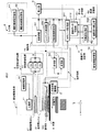
本発明の実施例におけるMRI装置の構成と機能につき図2乃至図4を用いて説明する。但し、図2は、本実施例におけるMRI装置の全体構成を示すブロック図である。
(Device configuration)
The configuration and functions of the MRI apparatus in the embodiment of the present invention will be described with reference to FIGS. However, FIG. 2 is a block diagram showing the overall configuration of the MRI apparatus in the present embodiment.
図2に示すMRI装置200は、被検体150に対して磁場を発生する静磁場発生部1及び傾斜磁場発生部2と、被検体150に対しRFパルスを照射しこの被検体150が発生するMR信号を検出する送受信部3と、被検体150を載置する天板4と、天板4を被検体150の体軸方向(z軸方向)へ移動させる天板移動機構部5を備えている。
An
又、MRI装置200は、被検体150に対して行なわれる位置決め用画像データの収集を目的としたパイロット撮影モード及び診断用画像データの収集を目的とした本撮影モードのMRI撮影にて送受信部3が検出したMR信号を再構成処理して画像歪み補正前の位置決め用画像データ(以下では、補正前画像データと呼ぶ。)を生成し、これらの補正前画像データにおいて発生した磁場の不均一性や非線形性に起因する画像歪みが補正された位置決め用画像データ(以下では、補正画像データと呼ぶ。)を生成する画像データ生成部6と、画像データ生成部6が生成したパイロット撮影モードの補正前画像データ及び補正画像データ、更には、本撮影モードの診断用画像データを表示する表示部8と、被検体情報の入力、撮影モードの選択、パルスシーケンス等を含んだMR信号収集条件の設定、画像データ生成条件及び画像データ表示条件の設定、補正前画像データに対する撮影断面の設定、補正画像データに対する撮影領域の設定、各種コマンド信号の入力等を行なう入力部9と、被検体150に印加される静磁場及び傾斜磁場の磁場情報(即ち、磁場強度分布データあるいは磁場誤差分布データ)が予め保管されている磁場情報保管部10と、MRI装置200における上述の各ユニットを制御する制御部15を備えている。
In addition, the
静磁場発生部1は、常伝導磁石あるいは超電導磁石によって構成される主磁石11と、この主磁石11に電流を供給する静磁場電源12を備え、図示しないガントリ中央部の撮影野に配置された被検体150に対し強力な静磁場を形成する。尚、主磁石11は、永久磁石によって構成されていてもよい。
The static magnetic field generation unit 1 includes a
一方、傾斜磁場発生部2は、被検体150の体軸方向(図1のz軸方向)とこの体軸方向に直交するx軸方向及びy軸方向に対して傾斜磁場を形成する傾斜磁場コイル21と、傾斜磁場コイル21の各々に対してパルス電流を供給する傾斜磁場電源22を備えている。
On the other hand, the gradient
傾斜磁場コイル21及び傾斜磁場電源22は、制御部15から供給されるシーケンス制御信号に基づき被検体150が置かれた撮影野に対して位置情報を付加する。即ち、傾斜磁場電源22は、制御部15から供給されるシーケンス制御信号に基づいてx軸方向,y軸方向及びz軸方向の傾斜磁場コイル21に供給するパルス電流を制御することにより各々の方向に対して傾斜磁場を形成する。そして、x軸方向,y軸方向及びz軸方向の傾斜磁場は合成されて互いに直交するスライス選択傾斜磁場、位相エンコード傾斜磁場及び周波数エンコード(読み出し)傾斜磁場が任意の方向に形成され、これらの傾斜磁場は、主磁石11によって形成された静磁場に重畳されて被検体150に印加される。
The gradient magnetic field coil 21 and the gradient magnetic
次に、送受信部3は、被検体150に対しRFパルスを照射すると共に被検体150から発生したMR信号を検出する送受信コイル31と、送受信コイル31に接続された送信部32及び受信部33を備えている。
Next, the transmission / reception unit 3 irradiates the subject 150 with an RF pulse and detects the MR signal generated from the subject 150, and the
送信部32は、位置決め用画像データの収集を目的としたパイロット撮影モード及び診断用画像データの収集を目的とした本撮影モードにおいて送受信コイル31に対しパルス電流を供給する機能を有し、図示しない基準信号発生器、変調器及び電力増幅器等を有している。前記基準信号発生器は、主磁石11の静磁場強度によって決定される磁気共鳴周波数(ラーモア周波数)と同じ周波数を有した基準信号を発生し、前記変調器は、この基準信号を所定の選択励起波形で変調してパルス電流を生成する。そして、得られたパルス電流は、前記電力増幅器を介して送受信コイル31へ供給され被検体150に対しRFパルスが照射される。
The
一方、受信部33は、前記RFパルスが照射された被検体150において発生し送受信コイル31によって検出されたMR信号に対して中間周波変換、位相検波、低周波増幅、フィルタリング、A/D変換等の信号処理を行なう。
On the other hand, the receiving
次に、天板4は、図示しない寝台の上面において被検体150の体軸方向(z軸方向)へスライド自在に取り付けられ、この天板4に載置された被検体150をz軸方向へ移動させることによりその撮影対象部位を撮影野の所望位置に設定する。一方、天板移動機構部5は、例えば、前記寝台の端部あるいは下部に取り付けられ、天板4を移動させるための駆動信号を制御部15から供給される天板移動制御信号に基づいて生成する。又、天板4を被検体150の体軸方向へ順次移動させながらMRI撮影を所定間隔で行なうことにより広範囲な位置決め用画像データや診断用画像データの収集も可能となる。
Next, the
一方、画像データ生成部6は、データ記憶部61と高速演算部62を備えている。データ記憶部61は、傾斜磁場の位相エンコードを順次更新することにより時系列的に収集される複数のMR信号をMRデータとして保存するMRデータ記憶部611を有し、更に、後述する高速演算部62の再構成処理部621が前記MRデータを再構成処理して生成した補正前画像データ及び画像歪み補正部622が前記補正前画像データの画像歪みを補正して新たに生成した補正画像データを記憶する画像データ記憶部612を有している。
On the other hand, the image
この画像データ記憶部612には、高速演算部62の再構成処理部621がMRデータ記憶部611から供給されるMRデータを再構成処理して生成したパイロット撮影モードの補正前画像データや本撮影モードの補正前診断用画像データが保存され、更に、高速演算部62の画像歪み補正部622が再構成処理部621から供給される上述の補正前画像データや補正前診断用画像データが有する画像歪みを補正して新たに生成したパイロット撮影モードの補正画像データ及び本撮影モードの補正診断用画像データが保存される。
In the image
一方、画像データ生成部6の高速演算部62は、再構成処理部621と画像歪み補正部622を備えている。再構成処理部621は、パイロット撮影モードあるいは本撮影モードにて収集されMR信号記憶部611に保存されたMRデータを読み出し、2次元フーリエ変換による画像再構成処理を行なって補正前画像データ及び画像歪み補正前診断用画像データを生成する。そして、得られた補正前画像データ及び補正前診断用画像データを画像歪み補正部622へ供給し、更に、前記補正前画像データを画像データ記憶部612に保存する。
On the other hand, the high-
次に、画像歪み補正部622は、再構成処理部621によって生成されたパイロット撮影モードにおける補正前画像データ及び本撮影モードにおける補正前診断用画像データが有する磁場誤差に起因した画像歪みを後述の磁場情報保管部10から供給される磁場情報(即ち、磁場強度分布データあるいは磁場誤差分布データ)に基づいて補正する機能を有し、図示しない演算処理部を備えている。
Next, the image
この画像歪み補正部622の演算処理部によって行なわれる画像歪みの補正方法について説明する。画像歪みの補正に際し前記演算処理部は、先ず、磁場情報保管部10から供給される磁場情報に対応した画像歪み量を補正前画像データの画素毎に算出し、例えば、z方向おいて磁場誤差が発生している場合、この誤差量とz方向に対する傾斜磁場の傾斜角度等に基づいてz方向の画像歪み量Δzを算出する。次いで、得られた画像歪み量Δzに基づき、補正前画像データの画素における画素値と当該画素からz方向にΔzだけ離れた画素の画素値との置き換えを行なう。そして、このような画素値の置き換えを補正前画像データを構成する全ての画素に対して行なうことにより磁場誤差に起因した画像歪みを補正することができる。
An image distortion correction method performed by the arithmetic processing unit of the image
次に、表示部8は、図示しない表示データ生成部、データ変換部及びモニタを備え、画像データ生成部6において生成された各種画像データの表示を行なう。即ち、パイロット撮影モードのMRI撮影によって収集された位置決め用画像データの表示に際し、前記表示データ生成部は、画像データ生成部6の画像データ記憶部612から供給される補正前画像データ及び補正画像データを所定の表示フォーマットに変換して表示データを生成し、前記データ変換部は、表示データ生成部が生成した表示データに対しD/A変換やテレビフォーマット変換等の変換処理を行なって前記モニタに表示する。
Next, the
一方、本撮影モードにおける診断用画像データの表示に際し、前記表示データ生成部は、上述の補正画像データに基づいて設定された撮影領域と補正前画像データに基づいて設定された撮影断面に対する本撮影モードのMRI撮影にて得られたMR信号を再構成処理して得られる画像歪み補正後の診断用画像データ(補正診断用画像データ)を所定の表示フォーマットに変換した後被検体情報等の付帯情報を付加して表示データを生成する。そして、前記データ変換部は、この表示データに対し所定の変換処理を行なって前記モニタに表示する。 On the other hand, when displaying diagnostic image data in the main imaging mode, the display data generation unit performs main imaging for the imaging region set based on the above-described corrected image data and the imaging cross section set based on the pre-correction image data. Diagnostic image data (corrected diagnostic image data) after image distortion correction obtained by reconstructing MR signals obtained by MRI imaging in the mode is converted into a predetermined display format and then supplemented with subject information and the like Display data is generated by adding information. The data conversion unit performs a predetermined conversion process on the display data and displays it on the monitor.
次に、入力部9は、制御部15を介して表示部8と接続されることによりインタラクティブなインターフェースを形成している。そして、操作卓上に表示パネルやスイッチ、キーボード、マウス等の各種入力デバイスを備え、パイロット撮影モードにて表示部8のモニタに表示された補正画像データに基づいて本撮影モードの撮影領域を設定する撮影領域設定機能91や前記モニタに表示された補正前画像データに基づいて本撮影モードの撮影断面を設定する撮影断面設定機能92を有している。又、被検体情報の入力、撮影モードの選択、パイロット撮影モード及び本撮影モードにおけるMR信号収集条件の設定、画像データ生成条件及び画像データ表示条件の設定、更には、各種コマンド信号の入力等も上述の表示パネルや入力デバイスを用いて行なわれる。
Next, the
次に、補正画像データに対する撮影領域の設定及び補正前画像データに対する撮影断面の設定につき図3を用いて説明する。図3(a)は、本撮影モードの診断用画像データとして被検体150のサジタル断面において収集される画像データ(診断用サジタル画像データ)Dsを示している。一方、図3(b)は、パイロット撮影モードにおいて収集された補正サジタル画像データDscに対して設定される診断用サジタル画像データの撮影領域Asを示しており、図3(c)は、パイロット撮影モードにおいて収集された補正前コロナル画像データDcxに対して設定される診断用サジタル画像データの撮影断面Scを示している。即ち、診断用画像データの撮影領域は、この診断用画像データと同一の断面において収集される補正画像データを用いて行なわれ、前記診断用画像データの撮影断面は、この診断用画像データと直交する断面にて収集される補正前画像データを用いて行なわれる。 Next, the setting of the photographing area for the corrected image data and the setting of the photographing section for the pre-correction image data will be described with reference to FIG. FIG. 3A shows image data (diagnostic sagittal image data) Ds collected in the sagittal section of the subject 150 as diagnostic image data in the main imaging mode. On the other hand, FIG. 3B shows the imaging region As of the diagnostic sagittal image data set for the corrected sagittal image data Dsc collected in the pilot imaging mode, and FIG. 3C shows the pilot imaging. The imaging | photography cross section Sc of the sagittal image data for a diagnosis set with respect to the coronal image data Dcx before correction | amendment collected in the mode is shown. That is, the imaging region of the diagnostic image data is performed using the corrected image data collected in the same cross section as the diagnostic image data, and the imaging cross section of the diagnostic image data is orthogonal to the diagnostic image data. This is performed using pre-correction image data collected at the cross section.
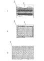
次に、本撮影モードの診断用画像データを生成する際の撮影断面の設定を補正前画像データを用いて行なう場合の有効性につき図4を用いて説明する。 Next, with reference to FIG. 4, description will be given of the effectiveness of setting the imaging section when generating diagnostic image data in the main imaging mode using the pre-correction image data.
尚、以下では、説明を判り易くするために、被検体150をy軸方向及びz軸方向に対し間隔dで配列された半径aを有する複数の円柱によって模擬する。図4(a)は、例えば、円柱の横断面がy軸方向及びz軸方向に2次元配列されるy−z平面に平行な被検体150のサジタル断面を示しており、図4(b)及び図4(c)は、このサジタル断面に対するMRI撮影によって収集された補正前画像データ及び補正画像データを示している。 In the following, for the sake of easy understanding, the subject 150 is simulated by a plurality of cylinders having a radius a arranged at intervals d in the y-axis direction and the z-axis direction. FIG. 4A shows a sagittal cross section of the subject 150 parallel to the yz plane in which a cylindrical cross section is two-dimensionally arranged in the y-axis direction and the z-axis direction, for example. FIG. 4C shows pre-correction image data and corrected image data collected by MRI imaging of this sagittal section.
但し、図4(b)の補正前画像データは、y軸方向に対して磁場誤差が発生した場合の画像歪み(即ち、破線で示した本来の画像情報が磁場誤差によってy方向へシフト)を有している。そして、このような補正前画像データの画像歪みを補正することにより図4(c)に示すような真の形状を有する補正画像データを得ることができる。 However, the uncorrected image data in FIG. 4B shows image distortion when a magnetic field error occurs in the y-axis direction (that is, the original image information indicated by the broken line is shifted in the y direction by the magnetic field error). Have. Then, corrected image data having a true shape as shown in FIG. 4C can be obtained by correcting the image distortion of the image data before correction.
このような補正前画像データ(図4(b))及び補正画像データ(図4(c))に示された画像情報に基づいて本撮影モードの撮影断面を設定した場合に得られるy−z平面に垂直な診断用画像データを図4(d)及び図4(e)に示す。 Yz obtained when the photographing section in the main photographing mode is set based on the image information shown in the pre-correction image data (FIG. 4B) and the corrected image data (FIG. 4C). The diagnostic image data perpendicular to the plane is shown in FIGS. 4 (d) and 4 (e).
例えば、図4(a)の最上段に示された7つの円柱を撮影対象部位とし、図4(b)の補正前画像データにおいて歪んだ状態(即ち、y軸方向にシフトした状態)で表示されている円柱横断面の配列方向に沿って本撮影モードの撮影断面Pxaを設定した場合、この撮影断面Pxaにおいて生成される本撮影モードの診断用画像データでは、図4(d)に示すように撮影対象部位に含まれた全ての円柱の縦断面(即ち、撮影対象部位の縦断面)を正確に観察することが可能となる。 For example, the seven cylinders shown in the uppermost part of FIG. 4A are taken as imaging target parts and displayed in a distorted state (that is, shifted in the y-axis direction) in the pre-correction image data of FIG. 4B. When the imaging section Pxa in the main imaging mode is set along the arrangement direction of the circular cylinder cross section, the diagnostic image data in the main imaging mode generated in the imaging section Pxa is as shown in FIG. In addition, it is possible to accurately observe the vertical cross sections of all the cylinders included in the imaging target region (that is, the vertical cross section of the imaging target region).
この場合、補正前画像データにおける円柱横断面のy軸方向に対するシフト量は磁場誤差の大きさに対応し、撮影断面の位置は送受信コイル31から放射されるRFパルスの中心周波数に対応している。従って、図4(b)に示すように磁場誤差によってy軸方向へシフトした補正前画像データの撮影対象部位に基づいて撮像断面Pxaを設定することによりPFパルスの中心周波数と当該円柱における磁気共鳴周波数を一致させることができるため、撮影対象部位における診断用画像データを収集することができる。
In this case, the shift amount in the y-axis direction of the cylindrical cross section in the pre-correction image data corresponds to the magnitude of the magnetic field error, and the position of the imaging cross section corresponds to the center frequency of the RF pulse radiated from the transmission /
これに対して、図4(c)の補正画像データに示された円柱横断面に沿って本撮影モードの撮影断面Pxbを設定した場合、PFパルスの中心周波数と円柱の磁気共鳴周波数は一致しないため、撮影断面Pxbにおいて生成される画像データは、図4(e)に示すように撮影対象部位に含まれた全ての円柱の縦断面を正確に観察することができない。従って、本撮影モードの診断用画像データを収集する際の撮影断面の設定は、パイロット撮影モードにおいて収集された補正前画像データを用いて行なうことが望ましい。 On the other hand, when the imaging section Pxb in the main imaging mode is set along the cylindrical cross section shown in the corrected image data of FIG. 4C, the center frequency of the PF pulse and the magnetic resonance frequency of the cylinder do not match. Therefore, the image data generated in the imaging section Pxb cannot accurately observe the longitudinal sections of all the cylinders included in the imaging target part as shown in FIG. Therefore, it is desirable to set the imaging section when collecting diagnostic image data in the main imaging mode using the pre-correction image data collected in the pilot imaging mode.
次に、磁場情報保管部10には、被検体150に印加される静磁場及び傾斜磁場の磁場情報が予め保管されている。この場合の磁場情報は、MRI装置200の静磁場発生部1及び傾斜磁場発生部2が図示しないガントリの撮影野に対して形成する静磁場及び傾斜磁場の磁場強度分布データであってもよく、又、静磁場及び傾斜磁場の実際の強度分布と理想的な強度分布との差異を示す磁場誤差分布データであっても構わない。この磁場情報の生成方法として計算機シミュレーションによる方法とファントムや当該被検体150を用いた事前の磁場計測による方法があり、特に後者の具体的な方法については既に示した特許文献1等に記載されているため詳細な説明は省略する。
Next, the magnetic field
一方、制御部15は、主制御部151、シーケンス制御部152及び天板移動制御部153を備えている。主制御部151は、図示しないCPUと記憶回路を備え、MRI装置200を統括して制御する機能を有している。そして、主制御部151の前記記憶回路には、入力部9において入力/設定/選択された被検体情報、撮影モード、パイロット撮影モード及び本撮影モードにおけるMR信号収集条件、画像データ生成条件及び画像データ表示条件、補正前画像データに対する撮影断面、補正画像データに対する撮影領域等の情報が保存される。一方、主制御部151のCPUは、特に、入力部9において設定されたパイロット撮影モード及び本撮影モードのMR信号収集条件に基づき傾斜磁場コイル21や送受信コイル31に供給するパルス電流の大きさ、極性、供給時間、供給タイミング等を設定してシーケンス制御部152へ供給することによりMR信号の収集を行なう。
On the other hand, the
シーケンス制御部152は、図示しないCPUと記憶回路を備え、主制御部151から供給される上述の設定情報を前記記憶回路に一旦保存した後、これらの設定情報に基づいてシーケンス制御信号を生成し傾斜磁場発生部2の傾斜磁場電源22や送受信部3の送信部32を制御する。又、天板移動制御部153は、入力部9から主制御部151を介して供給される天板移動指示信号に基づいて天板移動制御信号を生成し天板移動機構部5へ供給する。
The
(撮影断面及び撮影領域の設定手順)
次に、パイロット撮影モードにおいて行なわれる撮影断面及び撮影領域の設定手順につき図5のフローチャートを用いて説明する。
(Procedure for setting the shooting section and shooting area)
Next, a procedure for setting an imaging section and an imaging area performed in the pilot imaging mode will be described with reference to the flowchart of FIG.
当該被検体150のパイロット撮影に先立ちMRI装置200の操作者は、被検体150を天板4に載置した後入力部9において被検体情報の入力、パイロット撮影モード及び本撮影モードにおけるMR信号収集条件、画像データ生成条件及び画像データ表示条件の設定等を行なう。そして、これらの入力情報や設定情報は、主制御部151に備えられた記憶回路に保存される(図5のステップS1)。
Prior to pilot imaging of the subject 150, the operator of the
次いで、操作者は、入力部9においてパイロット撮影モードを選択した後撮影開始コマンドを入力する(図5のステップS2)。そして、このコマンド信号を受信した制御部15の主制御部151は、シーケンス制御部152に対してパイロット撮影モードに適用されるシーケンス情報を供給し、シーケンス制御部152は、このシーケンス情報に基づいて生成したシーケンス制御信号を傾斜磁場発生部2の傾斜磁場電源22及び送受信部3の送信部32へ供給することにより、当該被検体150に対するMR信号の収集を行なう。そして、得られたMR信号は、MRデータとしてデータ記憶部61のMRデータ記憶部611に保存される。
Next, the operator selects a pilot shooting mode at the
次いで、高速演算部62の再構成処理部621は、MRデータ記憶部611から読み出した上述のMRデータを再構成処理して補正前画像データを生成し、得られた補正前画像データを画像歪み補正部622へ供給すると共に画像データ記憶部612に保存する(図5のステップS3)。
Next, the
一方、高速演算部62の画像歪み補正部622は、再構成処理部621から供給された補正前画像データを受信し、磁場情報保管部10から読み出した磁場情報に基づき前記補正前画像データを補正して補正画像データを生成する(図5のステップS4)。そして、得られた補正画像データを画像データ記憶部612に保存する(図5のステップS5)。即ち、画像データ記憶部612には、補正前画像データと補正画像データが保存される。
On the other hand, the image
補正前画像データ及び補正画像データの収集と保存が終了したならば、表示部8の表示データ生成部は、表示データ記憶部612に一旦保存された上述の補正画像データを読み出し、所定の変換処理を行なって自己のモニタに表示する(図5のステップS6)。
When the collection and storage of the pre-correction image data and the corrected image data are completed, the display data generation unit of the
一方、表示部8に表示されたパイロット撮影モードの補正画像データを観測した操作者は、前記補正画像データに対し本撮影モードの診断用画像データ(即ち、前記補正画像データに対して略平行な断面における診断用画像データ)を収集するための撮影領域を入力部9が備えた撮影領域設定機能91を用いて設定する(図5のステップS7)。
On the other hand, the operator who has observed the corrected image data in the pilot shooting mode displayed on the
更に、前記表示データ生成部は、表示データ記憶部612に保存された補正前画像データを読み出して自己のモニタに表示し、(図5のステップS8)。表示部8に表示された補正前画像データを観測した操作者は、この補正前画像データに対する本撮影モードの撮影断面の設定を入力部9に設けられた撮影断面設定機能92を用いて行なう(図5のステップS9)。
Further, the display data generation unit reads out the pre-correction image data stored in the display
以上述べた手順によりパイロット撮影モードにおける撮影領域及び撮影断面の設定が終了したならば、操作者は、本撮影モードの選択と本撮影モード開始コマンドの入力を入力部9にて行なうことによりパイロット撮影モードを終了させる。
When the setting of the imaging area and the imaging section in the pilot imaging mode is completed by the procedure described above, the operator performs pilot imaging by selecting the actual imaging mode and inputting the actual imaging mode start command at the
以上述べた本発明の実施例によれば、磁場の不均一性や非直線性等に起因して発生する画像歪みが補正される前の位置決め用画像データを用いて診断用画像データの撮影断面を設定し、画像歪みが補正された位置決め用画像データを用いて診断用画像データの撮影領域を設定することにより、診断用画像データを収集する際の好適な撮影断面及び撮影領域を高い精度で設定することができる。このため、磁場の誤差にあまり影響されることなく診断に有効な画像データを収集することが可能となる。 According to the embodiment of the present invention described above, the imaging cross section of the diagnostic image data using the positioning image data before the image distortion generated due to the non-uniformity or non-linearity of the magnetic field is corrected. And setting the imaging area of the diagnostic image data using the positioning image data whose image distortion has been corrected, so that a suitable imaging section and imaging area when collecting diagnostic image data can be obtained with high accuracy. Can be set. For this reason, it is possible to collect image data effective for diagnosis without being significantly affected by the error of the magnetic field.
特に、診断用画像データの撮影領域は、この診断用画像データと同一の断面において収集される補正画像データを用いて行ない、前記診断用画像データの撮影断面は、前記診断用画像データと直交する断面にて収集された補正前画像データを用いて行なうことにより、撮影領域及び撮影断面の設定を容易かつ正確に行なうことができる。 In particular, the imaging region of the diagnostic image data is performed using corrected image data collected in the same cross section as the diagnostic image data, and the imaging cross section of the diagnostic image data is orthogonal to the diagnostic image data. By using the pre-correction image data collected in the cross section, it is possible to easily and accurately set the imaging region and the imaging cross section.
以上、本発明の実施例について述べてきたが、本発明は、上述の実施例に限定されるものではなく変形して実施してもよい。例えば、上述の実施例では図3に示したように、パイロット撮影モードにおいて収集された補正サジタル画像データ及び補正前コロナル画像データに基づいて本撮影モードのサジタル画像データに対する撮影領域及び撮影断面を設定する場合について述べたが、これに限定されるものではない。即ち、補正コロナル画像データ及び補正前サジタル画像データに基づいて本撮影モードのコロナル画像データに対する撮影領域及び撮影断面を設定してもよく、又、補正前サジタル画像データあるいは補正前コロナル画像データと補正アキシャル画像データに基づいて本撮影モードのアキシャル画像データに対する撮影領域及び撮影断面を設定してもよい。 Although the embodiments of the present invention have been described above, the present invention is not limited to the above-described embodiments and may be modified. For example, in the above-described embodiment, as shown in FIG. 3, the imaging region and the imaging section for the sagittal image data in the main imaging mode are set based on the corrected sagittal image data and the pre-correction coronal image data collected in the pilot imaging mode. However, the present invention is not limited to this. That is, the shooting area and the shooting section for the coronal image data in the main shooting mode may be set based on the corrected coronal image data and the sagittal image data before correction. Based on the axial image data, a shooting area and a shooting section for the axial image data in the main shooting mode may be set.
例えば、本実施例の変形例として、補正コロナル画像データ及び補正前サジタル画像データに基づいて本撮影モードのコロナル画像データに対する撮影領域及び撮影断面を設定する場合につき図6を用いて説明する。 For example, as a modification of the present embodiment, a case where a shooting area and a shooting cross section for the coronal image data in the main shooting mode are set based on the corrected coronal image data and the sagittal image data before correction will be described with reference to FIG.
図6(a)は、本撮影モードの診断用画像データとして被検体150のコロナル断面に対して収集される診断用コロナル画像データDcを示している。一方、図6(b)は、補正コロナル画像データDccに対して設定される診断用コロナル画像データの撮影領域Acを示しており、図6(c)は、補正前サジタル画像データDsxに対して設定される診断用コロナル画像データの撮影断面Ssを示している。即ち、診断用コロナル画像データの撮影領域は、この診断用コロナル画像データと同一の断面において収集される補正コロナル画像データを用いて行なわれ、前記診断用コロナル画像データの撮影断面は、この診断用コロナル画像データと直交するサジタル断面にて収集された補正前サジタル画像データを用いて行なわれる。 FIG. 6A shows diagnostic coronal image data Dc collected for the coronal section of the subject 150 as diagnostic image data in the main imaging mode. On the other hand, FIG. 6B shows the imaging region Ac of diagnostic coronal image data set for the corrected coronal image data Dcc, and FIG. 6C shows the sagittal image data Dsx before correction. The imaging | photography cross section Ss of the diagnostic coronal image data set is shown. That is, the imaging region of the diagnostic coronal image data is performed using the corrected coronal image data collected in the same cross section as the diagnostic coronal image data. This is performed using the uncorrected sagittal image data collected at a sagittal section orthogonal to the coronal image data.
一方、画像歪み補正に用いられる磁場強度分布データや磁場誤差分布データ等の磁場情報は、磁場情報保管部10に予め保管されている場合について述べたが、当該MRI撮影に先立って行なうシミュレーションや磁場計測によって収集してもよい。この場合、被検体150の撮影対象部位をガントリの撮影野へ配置した状態で磁場情報を計測することにより、被検体150の挿入に起因した画像歪みを併せて補正することが可能となる。
On the other hand, magnetic field information such as magnetic field intensity distribution data and magnetic field error distribution data used for image distortion correction has been described as being stored in advance in the magnetic field
更に、上述の実施例では、互いに直交する断面において収集された1枚の補正画像データ及び補正前画像データに基づいて本撮影モードの撮影領域と撮影断面を設定する場合について述べたが、被検体150の撮影対象部位が体軸方向に対し比較的広い範囲に存在する場合、天板4の移動により体軸方向の異なる位置にて収集された複数の補正画像データを合成して広範囲補正画像データを生成し、この広範囲補正画像データに基づいて本撮影モードの撮影領域を設定してもよい。
Furthermore, in the above-described embodiment, the case where the imaging region and the imaging cross section in the main imaging mode are set based on one corrected image data and pre-correction image data collected in cross sections orthogonal to each other has been described. When 150 imaging target parts exist in a relatively wide range with respect to the body axis direction, a plurality of correction image data collected at different positions in the body axis direction by the movement of the
尚、上述の実施例では、被検体150に対するRFパルスの照射と被検体150が発生するMR信号の受信を可能とする送受信兼用のコイルを用いてMRI撮影を行なう場合について述べたが、送信専用のコイル及び受信専用のコイルを用いてもよい。 In the above-described embodiment, the case where MRI imaging is performed using a coil for both transmission and reception that enables irradiation of an RF pulse to the subject 150 and reception of an MR signal generated by the subject 150 has been described. Alternatively, a receiving coil and a receiving-only coil may be used.
1…静磁場発生部
11…主磁石
12…静磁場電源
2…傾斜磁場発生部
21…傾斜磁場コイル
22…傾斜磁場電源
3…送受信部
31…送受信コイル
32…送信部
33…受信部
4…天板
5…天板移動機構部
6…画像データ生成部
61…データ記憶部
611…MRデータ記憶部
612…画像データ記憶部
62…高速演算部
621…再構成処理部
622…画像歪み補正部
8…表示部
9…入力部
91…撮影領域設定機能
92…撮影断面設定機能
10…磁場情報保管部
15…制御部
151…主制御部
152…シーケンス制御部
153…天板移動制御部
200…MRI装置
DESCRIPTION OF SYMBOLS 1 ... Static magnetic
Claims (7)
前記MRI撮影によって収集されたMRデータを再構成処理して前記複数の断面における第1の位置決め用画像データを生成する再構成処理手段と、
前記複数の断面において生成された複数からなる前記第1の位置決め用画像データの少なくとも何れかに対し、この第1の位置決め用画像データが有する磁場誤差に起因した画像歪みを補正して第2の位置決め用画像データを生成する画像歪み補正手段と、
所望の断面において生成された前記第2の位置決め用画像データに基づいて前記本撮影モードの撮影領域を設定する撮影領域設定手段と、
前記所望の断面と異なる断面において生成された前記第1の位置決め用画像データに基づいて前記本撮影モードの撮影断面を設定する撮影断面設定手段とを
備えたことを特徴とするMRI装置。 Imaging in the main imaging mode based on positioning image data in a plurality of crossing sections acquired by performing MRI imaging in a pilot imaging mode preceding the main imaging mode on a subject to which a static magnetic field and a gradient magnetic field are applied. In an MRI apparatus for setting a cross section and an imaging region,
Reconstruction processing means for reconstructing MR data collected by the MRI imaging and generating first positioning image data in the plurality of cross sections;
The image distortion caused by the magnetic field error of the first positioning image data is corrected for at least one of the plurality of first positioning image data generated in the plurality of cross sections to obtain a second Image distortion correction means for generating positioning image data;
Shooting area setting means for setting a shooting area in the main shooting mode based on the second positioning image data generated in a desired section;
An MRI apparatus, comprising: an imaging section setting means for setting an imaging section in the main imaging mode based on the first positioning image data generated in a section different from the desired section.
前記MRI撮影によって収集されたMRデータを再構成処理して前記複数の断面における第1の位置決め用画像データを生成する再構成処理機能と、
前記複数の断面において生成された複数からなる前記第1の位置決め用画像データの少なくとも何れかに対し、この第1の位置決め用画像データが有する磁場誤差に起因した画像歪みを補正して第2の位置決め用画像データを生成する画像歪み補正機能と、
所望の断面において生成された前記第2の位置決め用画像データに基づいて前記本撮影モードの撮影領域を設定する撮影領域設定機能と、
前記所望の断面と異なる断面において生成された前記第1の位置決め用画像データに基づいて前記本撮影モードの撮影断面を設定する撮影断面設定機能を
実行させることを特徴とする撮影領域設定用制御プログラム。 Imaging in the main imaging mode based on positioning image data in a plurality of crossing sections acquired by performing MRI imaging in a pilot imaging mode preceding the main imaging mode on a subject to which a static magnetic field and a gradient magnetic field are applied. For the MRI device that sets the cross-section and imaging area,
A reconstruction processing function for reconstructing MR data collected by the MRI imaging to generate first positioning image data in the plurality of cross sections;
The image distortion caused by the magnetic field error of the first positioning image data is corrected for at least one of the plurality of first positioning image data generated in the plurality of cross sections to obtain a second An image distortion correction function for generating positioning image data;
A shooting area setting function for setting a shooting area in the main shooting mode based on the second positioning image data generated in a desired section;
An imaging area setting control program for executing an imaging section setting function for setting an imaging section in the main imaging mode based on the first positioning image data generated in a section different from the desired section. .
Priority Applications (1)
| Application Number | Priority Date | Filing Date | Title |
|---|---|---|---|
| JP2009243458A JP5378149B2 (en) | 2009-10-22 | 2009-10-22 | MRI apparatus and imaging area setting control program |
Applications Claiming Priority (1)
| Application Number | Priority Date | Filing Date | Title |
|---|---|---|---|
| JP2009243458A JP5378149B2 (en) | 2009-10-22 | 2009-10-22 | MRI apparatus and imaging area setting control program |
Publications (2)
| Publication Number | Publication Date |
|---|---|
| JP2011087758A JP2011087758A (en) | 2011-05-06 |
| JP5378149B2 true JP5378149B2 (en) | 2013-12-25 |
Family
ID=44106621
Family Applications (1)
| Application Number | Title | Priority Date | Filing Date |
|---|---|---|---|
| JP2009243458A Expired - Fee Related JP5378149B2 (en) | 2009-10-22 | 2009-10-22 | MRI apparatus and imaging area setting control program |
Country Status (1)
| Country | Link |
|---|---|
| JP (1) | JP5378149B2 (en) |
Families Citing this family (3)
| Publication number | Priority date | Publication date | Assignee | Title |
|---|---|---|---|---|
| JP6076603B2 (en) * | 2012-02-06 | 2017-02-08 | 東芝メディカルシステムズ株式会社 | Magnetic resonance imaging device |
| JP7187206B2 (en) * | 2018-08-06 | 2022-12-12 | キヤノンメディカルシステムズ株式会社 | Magnetic resonance imaging device |
| JP7158964B2 (en) * | 2018-09-14 | 2022-10-24 | キヤノンメディカルシステムズ株式会社 | Magnetic resonance imaging device |
Family Cites Families (3)
| Publication number | Priority date | Publication date | Assignee | Title |
|---|---|---|---|---|
| JP3378278B2 (en) * | 1991-10-30 | 2003-02-17 | 株式会社東芝 | Positioning imaging method and MRI apparatus in MRI |
| US6844884B2 (en) * | 2000-12-27 | 2005-01-18 | Ge Medical Systems Global Technology Company, Llc | Multi-plane graphic prescription interface and method |
| JP4253241B2 (en) * | 2003-10-20 | 2009-04-08 | 株式会社東芝 | Magnetic resonance imaging system |
-
2009
- 2009-10-22 JP JP2009243458A patent/JP5378149B2/en not_active Expired - Fee Related
Also Published As
| Publication number | Publication date |
|---|---|
| JP2011087758A (en) | 2011-05-06 |
Similar Documents
| Publication | Publication Date | Title |
|---|---|---|
| JP5518403B2 (en) | Magnetic resonance imaging apparatus and magnetic resonance imaging method | |
| JP5366484B2 (en) | Magnetic resonance imaging apparatus and analysis method of fat suppression effect in the magnetic resonance imaging apparatus | |
| US9297876B2 (en) | Magnetic resonance imaging apparatus and eddy current compensation method | |
| JP5086796B2 (en) | Magnetic resonance imaging apparatus, magnetic resonance imaging maintenance apparatus, magnetic resonance imaging maintenance system, and magnetic resonance imaging apparatus inspection method | |
| US20120319689A1 (en) | Magnetic resonance imaging apparatus | |
| JP2012040362A (en) | Magnetic resonance imaging method, magnetic resonance imaging apparatus, and control device of magnetic resonance imaging apparatus | |
| JP2009006132A (en) | Magnetic resonance imaging apparatus | |
| JP5075344B2 (en) | MRI apparatus and image display apparatus | |
| JP2007190114A (en) | Magnetic resonance imaging apparatus | |
| JP5378149B2 (en) | MRI apparatus and imaging area setting control program | |
| JP5268372B2 (en) | Magnetic resonance imaging apparatus and image data generation method | |
| JP5675044B2 (en) | Magnetic resonance imaging system | |
| JP2009195584A (en) | Image processor and medical imaging apparatus | |
| JP5177379B2 (en) | Magnetic resonance imaging system | |
| JP5336731B2 (en) | Magnetic resonance imaging system | |
| JP7308097B2 (en) | METHOD OF SETTING EXCITATION AREA AND MAGNETIC RESONANCE IMAGING DEVICE | |
| JP4901420B2 (en) | Magnetic resonance imaging apparatus and magnetic resonance imaging method | |
| JP2006129937A (en) | Magnetic resonance imaging apparatus | |
| JP2010094156A (en) | Mri apparatus | |
| JP5064685B2 (en) | Magnetic resonance imaging system | |
| JP2008017925A (en) | Nuclear magnetic resonance imaging apparatus | |
| JP5710161B2 (en) | MRI apparatus and control program | |
| JP5484001B2 (en) | Magnetic resonance imaging apparatus and image correction method | |
| JP4969933B2 (en) | Magnetic resonance imaging system | |
| JP6718764B2 (en) | Magnetic resonance imaging apparatus and control method thereof |
Legal Events
| Date | Code | Title | Description |
|---|---|---|---|
| RD02 | Notification of acceptance of power of attorney |
Free format text: JAPANESE INTERMEDIATE CODE: A7422 Effective date: 20111128 |
|
| RD04 | Notification of resignation of power of attorney |
Free format text: JAPANESE INTERMEDIATE CODE: A7424 Effective date: 20111206 |
|
| A621 | Written request for application examination |
Free format text: JAPANESE INTERMEDIATE CODE: A621 Effective date: 20120928 |
|
| TRDD | Decision of grant or rejection written | ||
| A977 | Report on retrieval |
Free format text: JAPANESE INTERMEDIATE CODE: A971007 Effective date: 20130828 |
|
| A01 | Written decision to grant a patent or to grant a registration (utility model) |
Free format text: JAPANESE INTERMEDIATE CODE: A01 Effective date: 20130830 |
|
| A61 | First payment of annual fees (during grant procedure) |
Free format text: JAPANESE INTERMEDIATE CODE: A61 Effective date: 20130925 |
|
| R150 | Certificate of patent or registration of utility model |
Ref document number: 5378149 Country of ref document: JP Free format text: JAPANESE INTERMEDIATE CODE: R150 Free format text: JAPANESE INTERMEDIATE CODE: R150 |
|
| S111 | Request for change of ownership or part of ownership |
Free format text: JAPANESE INTERMEDIATE CODE: R313117 |
|
| R350 | Written notification of registration of transfer |
Free format text: JAPANESE INTERMEDIATE CODE: R350 |
|
| S533 | Written request for registration of change of name |
Free format text: JAPANESE INTERMEDIATE CODE: R313533 |
|
| R350 | Written notification of registration of transfer |
Free format text: JAPANESE INTERMEDIATE CODE: R350 |
|
| LAPS | Cancellation because of no payment of annual fees |