JP4658552B2 - Embedded ceiling air conditioner - Google Patents
Embedded ceiling air conditioner Download PDFInfo
- Publication number
- JP4658552B2 JP4658552B2 JP2004285684A JP2004285684A JP4658552B2 JP 4658552 B2 JP4658552 B2 JP 4658552B2 JP 2004285684 A JP2004285684 A JP 2004285684A JP 2004285684 A JP2004285684 A JP 2004285684A JP 4658552 B2 JP4658552 B2 JP 4658552B2
- Authority
- JP
- Japan
- Prior art keywords
- duct
- opening
- ceiling
- outlet
- scheduled
- Prior art date
- Legal status (The legal status is an assumption and is not a legal conclusion. Google has not performed a legal analysis and makes no representation as to the accuracy of the status listed.)
- Expired - Lifetime
Links
Images


Landscapes
- Duct Arrangements (AREA)
- Air Filters, Heat-Exchange Apparatuses, And Housings Of Air-Conditioning Units (AREA)
Description
本発明は、被調和室の天井に埋め込まれ、略箱形の筐体内に熱交換器及び送風機を収容したユニット本体を有し、このユニット本体の筐体に吹出ダクトが選択的に連結される天井埋込型空気調和装置に関する。 The present invention has a unit main body embedded in a ceiling of a conditioned room and containing a heat exchanger and a blower in a substantially box-shaped casing, and a blowout duct is selectively connected to the casing of the unit main body. The present invention relates to a ceiling-embedded air conditioner.
従来より、被調和室の天井に埋め込まれ、略箱形の筐体内に熱交換器及び送風機を収容したユニット本体を有する天井埋込型空気調和装置が知られている。
この種の天井埋込型空気調和装置には、吸込口と吹出口を有する化粧パネルを取り付け、この化粧パネルの吹出口から熱交換器で熱交換された調和空気を吹き出す構成のものや、ユニット本体の筐体の側面にダクト口を備え、このダクト口に連結された吹出ダクトを介して調和空気を吹き出す構成のものがある。
この吹出ダクトを有する空気調和装置には、ダクト口に回動可能な円板を配置し、この円板により吹出ダクトへの風量を調整可能にしたものがある(例えば、特許文献1参照)。
This type of ceiling-embedded air conditioner has a configuration in which a decorative panel having a suction port and an air outlet is attached, and conditioned air heat-exchanged by a heat exchanger is blown out from the air outlet of the decorative panel, or a unit There is a configuration in which a duct port is provided on a side surface of the casing of the main body, and conditioned air is blown out through a blowing duct connected to the duct port.
Some air conditioners having this blowout duct include a rotatable disk disposed at the duct opening, and the volume of air to the blowout duct can be adjusted by this disk (see, for example, Patent Document 1).
しかし、ダクト口に風量調整用の円板を配置する構成では、部品点数が増え、組み立てが煩雑になる等の問題がある。
ところで、近年、吸込口と吹出口を有する化粧パネルを備えた天井埋込型空気調和装置においては、ユーザの要望に応じて吹出ダクトを連結し、この吹出ダクトと化粧パネルの吸込口の両方から、或いは、いずれか一方から調和空気を吹出可能にできるものが要望されている。この場合、この天井埋込型空気調和装置においては、吹出ダクトの後付けにも容易に対応できるように、吹出ダクトを連結した場合における風量調整をより簡易にできるように構成しておくことがより一層望まれる。
However, in the configuration in which the air volume adjusting disk is arranged at the duct opening, there are problems that the number of parts increases and the assembly becomes complicated.
By the way, in recent years, in a ceiling-embedded air conditioner equipped with a decorative panel having a suction port and a blower outlet, a blower duct is connected according to a user's request, and from both the blower duct and the suction port of the decorative panel. Alternatively, there is a demand for one that can blow out conditioned air from either one. In this case, in this ceiling-embedded air conditioner, it is possible to make it easier to adjust the air volume when the blowout duct is connected so that it can be easily applied to the retrofit of the blowout duct. More desired.
そこで、本発明の目的は、吹出ダクトを後付けする場合でも、吹出ダクトへの風量調整を、部品点数を増やすことなく、容易に行うことができる天井埋込型空気調和装置を提供することにある。 Therefore, an object of the present invention is to provide a ceiling-embedded air conditioner that can easily adjust the air volume to the blowout duct without increasing the number of parts even when the blowout duct is retrofitted. .
上述課題を解決するため、本発明は、被調和室の天井に埋め込まれ、略箱形の筐体内に熱交換器及び送風機を収容したユニット本体と、天井面に取り付けられ、吹出口及び吸込口を有する化粧グリルとを備え、前記筐体に吹出ダクトが選択的に連結される天井埋込型空気調和装置において、前記筐体における前記吹出ダクトの連結予定面に、前記吹出ダクトと選択的に連通可能な複数の開口予定口の縁部に沿ったノックアウトホールを間隔を空けて形成し、前記複数の開口予定口は、前記吹出ダクトと前記化粧パネルの吹出口とに供給される調和空気の配分比率を吹出口側の方を多くするダクト予定口(D2,D4)と、このダクト予定口(D2,D4)と共に開口されて前記調和空気の配分比率を前記吹出ダクト側の方を多くする他のダクト予定口(D1,D3)とを有し、前記吹出ダクトが、前記ダクト予定口(D2,D4)と前記他のダクト予定口(D1,D3)とに連通する開口部を有し、この開口部に、内側に向けて延出して前記筐体にピン連結されるフランジを設け、このフランジに、前記ダクト予定口(D2,D4)の下縁部に引っ掛けられて該吹出ダクトのダクト口側を浮かし前記吹出ダクトの連結位置を位置合わせ可能にする引掛部材を設けたことを特徴とする。 In order to solve the above-mentioned problems, the present invention provides a unit body embedded in a ceiling of a conditioned room and containing a heat exchanger and a blower in a substantially box-shaped housing, and attached to the ceiling surface. A ceiling-embedded air conditioner in which a blowout duct is selectively connected to the casing, and a surface to be connected to the blowout duct in the casing is selectively connected to the blowout duct. Knockout holes are formed at intervals along edges of a plurality of planned opening openings that can communicate with each other , and the plurality of planned opening openings are provided for conditioned air supplied to the blowout duct and the blowout opening of the decorative panel. Duct scheduled openings (D2, D4) that increase the distribution ratio on the outlet side, and the duct planned openings (D2, D4) are opened together to increase the distribution ratio of the conditioned air on the outlet duct side. Other duck A predetermined opening (D1, D3), and the outlet duct has an opening communicating with the predetermined duct opening (D2, D4) and the other predetermined duct opening (D1, D3). A flange extending to the inside and pin-coupled to the housing is provided on the part, and the flange is hooked on the lower edge of the planned duct opening (D2, D4) to the duct opening side of the blowing duct A hooking member is provided which floats and makes it possible to align the connection position of the blowing duct .
また、本発明は、上記構成において、前記ダクト予定口(D2,D4)の縁部に沿った前記ノックアウトホールの一部は、前記他のダクト予定口(D1,D3)の縁部に沿ったノックアウトホールの一部を兼用することを特徴とする。また、本発明は、上記構成において、前記筐体の内側には、断熱材が配置され、この断熱材が、前記ノックアウトホールを介して前記筐体内に外気が侵入するのを防止することを特徴とする。
Further, according to the present invention, in the above configuration, a part of the knockout hole along the edge of the scheduled duct (D2, D4) is along the edge of the other scheduled duct (D1, D3) . A part of the knockout hall is also used. Further, in the above configuration, the present invention is characterized in that a heat insulating material is disposed inside the housing, and the heat insulating material prevents outside air from entering the housing through the knockout hole. And
本発明は、筐体における吹出ダクトの連結予定面に、吹出ダクトと選択的に連通可能な複数の開口予定口の縁部に沿ったノックアウトホールを間隔を空けて形成したため、吹出ダクトへの風量調整用の円板を備える従来のものに比して、部品点数を増やすことなく、容易に吹出ダクトへの風量を調整することができ、吹出ダクトの後付けも容易になる。 In the present invention, the knockout holes along the edges of the plurality of opening openings that can be selectively communicated with the blowout duct are formed on the planned connection surface of the blowout duct in the housing at intervals, so that the air volume to the blowout duct Compared with the conventional one provided with a disk for adjustment, the air volume to the blowout duct can be easily adjusted without increasing the number of parts, and retrofitting of the blowout duct is facilitated.
以下、図面を参照して本発明の実施形態を詳述する。
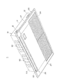
図1は本実施の形態に係る天井埋込型空気調和装置(以下、空気調和装置という)1の外観構成を示す斜視図であり、図2は断面図である。この空気調和装置1は、送風機2や熱交換器3を収容するユニット本体10と、このユニット本体10の下方にねじで固定される化粧パネル20とを備えている。
ユニット本体10は、板金製の箱形の筐体11を有し、この筐体11の外壁面には、天井梁に取り付けられた吊下げボルト(図示せず)に連結される複数の吊り金具12が設けられ、この吊り金具12によりユニット本体10が被調和室の天井空間内に配置される。
Hereinafter, embodiments of the present invention will be described in detail with reference to the drawings.
FIG. 1 is a perspective view showing an external configuration of a ceiling-embedded air conditioner (hereinafter referred to as an air conditioner) 1 according to the present embodiment, and FIG. 2 is a cross-sectional view. The
The unit
化粧パネル20は、ユニット本体10の筐体11より大きい略四角形状の外観形状を有し、図2に示すように、ユニット本体10を天井4に挿入する際の天井穴5を塞ぐように天井4に取り付けられ、化粧パネル20の長手方向の一方の側縁部に沿って、被調和室内の空気を吸い込むための吸込口21が形成され、他方の側縁部に沿って、空気の吹出口22が形成されている。この化粧パネル20の吸込口21には、フィルタ23を支持する吸込グリル24が着脱自在に配置され、化粧パネル20の吹出口22には、化粧パネル20の幅方向に延在するルーバ25が配置されている。このルーバ25は図示せぬモータの駆動により軸26を支点に回動可能に支持されている。
また、この化粧パネル20は、図1に示すように、筐体11の吊り金具12に対向する位置に着脱可能なサイドパネル27を備え、このサイドパネル27を外すと、吊り金具12が露出し、作業者が室内からユニット本体10の高さを調整できるようになっている。
The
Further, as shown in FIG. 1, the
ユニット本体10には、図2及び図3に示すように、筐体11の内部空間を機械室30と熱交換室31とに仕切る仕切り板32が設けられ、機械室30には、送風機2及び電装箱6が配置され、熱交換室31には熱交換器3及び熱交換器3に連結される冷媒配管7が配置される。この冷媒配管7は、図示せぬ室外ユニットから供給される冷媒を熱交換器3に送る冷媒送り管や、熱交換器3を循環した冷媒を室外ユニットに戻す冷媒戻し管の一部を構成している。
As shown in FIGS. 2 and 3, the unit
送風機2は、多翼ファン35を収容する2つのファンユニット36と、各ファンユニット36の多翼ファン35を回転駆動するモータ37とを備え、電装箱6に収容された制御基板からの駆動信号に基づいてモータ37が駆動し、図2に示すように、化粧パネル20の吸込口21を介して被調和室内の空気を吸い込み、フィルタ23により清浄化された室内空気を熱交換室31に向けて送風する。
The
熱交換器3は、フィン・チューブ型の熱交換器が適用され、熱交換面積を多く確保すべく、熱交換室31に斜めに配置(傾斜配置)されている。この熱交換器3の下方には、発泡ポリスチレン製のドレンパン38が設置され、熱交換器3の結露水が被調和室に漏れないようにすると共に、このドレンパン38が熱交換室31を断熱する断熱材の一部を兼ねている。この熱交換室31は、ドレンパン38の他に、筐体11の内壁面に沿って配置される発泡ポリスチレン製の断熱材40によって断熱されている。
The
上記構成により、この空気調和装置1においては、被調和室の室内空気が、図2に矢印で示すように、送風機2により化粧パネル20の吸込口21からフィルタ23を介してユニット本体10内に吸い込まれた後、熱交換器3に向けて吹き出され、熱交換器3で熱交換された後に、ユニット本体10の内壁面10Aに衝突してほぼ直交する方向に向きを変え、化粧パネル20の吹出口22から吹き出される。これによって室内空気がユニット本体10内の熱交換器3を循環し、室内温度の調整(室内空調)が可能となっている。
With this configuration, in the
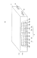
ところで、この空気調和装置1には、ユーザの要望等に応じてユニット本体10の筐体11の側壁11Xに吹出ダクト50(図5)が選択的に連結され、この吹出ダクト50を通じて、熱交換器3で熱交換された調和空気が被調和室に吹き出し可能とされる。本実施形態では、この吹出ダクト50が連結される側壁11Xの外壁面(連結予定面)11Aには、図4に示すように、吹出ダクト50のダクト予定口Dの縁部に沿ったノックアウトホール60が間隔を空けて形成され、このノックアウトホール60をつなぐようにノックアウトホール60間の部材を切断することによって、吹出ダクト50のダクト口D0を簡易に形成できるようになっている。
By the way, in this
より具体的には、本実施形態では、ダクト予定口Dとして、図4に示すように、左右対称に、縦2列、横2列の4つのダクト予定口D1〜D4を想定しており、各ダクト予定口D1〜D4の縁部に沿って細穴形状のノックアウトホール60が間隔を空けて形成される。ここで、縦に並ぶダクト予定口D1及びD2ついては、上方のダクト予定口D1の下縁部に沿ったノックアウトホール60が、下方のダクト予定口D2の上縁部に沿ったノックアウトホール60を兼用しており、これによって、ダクト予定口D1とD2とが離間するようにノックアウトホール60を夫々形成した場合に比して、ノックアウトホール60の数を低減でき、ノックアウトホール60の加工の手間を軽減することができる。
More specifically, in the present embodiment, as the planned duct opening D, as shown in FIG. 4, four vertical planned duct openings D1 to D4 in two rows and two horizontal rows are assumed, A narrow hole-shaped
また、縦に並ぶダクト予定口D3及びD4ついても、ダクト予定口D1及びD2と同様に一方のダクト予定口D3の縁部に沿ったノックアウトホール60が、他のダクト予定口D4の縁部に沿ったノックアウトホール60を兼用するようになっており、ノックアウトホール60の加工の手間を軽減している。なお、これらノックアウトホール60の内側には、上記したように、断熱材40が配置されるため、この断熱材40によって、ノックアウトホール60を介して外気がユニット本体10内に侵入することが防止され、ユニット本体10内の断熱が維持される。
In addition, with respect to the planned duct openings D3 and D4 arranged vertically, the
図5は吹出ダクト50の一例を示す斜視図である。この吹出ダクト50は、空気調和装置1のユニット本体10に連結される金属製の筒体51と、天井等に設けた開口(吹出ダクト送風口)に連通させられる金属製の筒体52と、これら筒体51、52を連結し、柔軟材料により形成される連結体53とから概略構成され、この連結体53により一方の筒体53の向きを他方の筒体52に対して任意の方向に変更できるようになっている。この筒体51の開口部51Aには、内側に向けて延出するフランジ54が設けられ、このフランジ54には、複数のピン穴55が設けられると共に、引掛部材56が間隔を空けてピンで連結されている。この引掛部材56は、金属製の板部材を略コの字状に屈曲して形成され、このコの字部分がユニット本体10に引っ掛け可能に形成されている。この引掛部材56は、コの字部分がユニット本体10に引っ掛けられることにより、吹出ダクト50開口部51A側をユニット本体10の取付位置に仮支持するようになっている。
FIG. 5 is a perspective view showing an example of the
図6A及び図6Bは、空気調和装置1のユニット本体10に吹出ダクト50を連結した状態を示す一部断面図である。これら図に示すように、ユニット本体10に吹出ダクト50を連結する場合は、ユニット本体10のダクト予定口D1〜D4のいずれか1つ以上をダクト口D0として開口させると共に、このダクト口D0を遮っていた断熱材40の一部を切断してダクト口D0と熱交換室31とを連通させた後、さらに、このユニット本体10の連結予定面11Aに、吹出ダクト50のピン穴55に対応する位置に雌ねじ穴を形成し、この雌ねじ穴にピン挿通部55を介して吹出ダクト50をピン締結することにより、ユニット本体10に吹出ダクト50が連結される。この場合、吹出ダクト50から吹き出す風量を左右で均等にするために、ダクト予定口D1をダクト口D0とする場合は、ダクト予定口D3もダクト口D0とすることが好ましく、同様に、ダクト予定口D2をダクト口D0とする場合は、ダクト予定口D4もダクト口D0とすることが好ましい。
6A and 6B are partial cross-sectional views showing a state in which the blowing
また、上記のように、ユニット本体10に吹出ダクト50を連結する際には、吹出ダクト50の引掛部材56を引き出して、ユニット本体10のダクト口D0の下縁部D0Lに断熱クッション材57を介して引っ掛けることによって、吹出ダクト50のダクト口側を浮かせた状態にし、この状態で吹出ダクト50の位置合わせを行ってピン連結する。このため、吹出ダクト50のダクト口側を一回持ち上げれば、引掛部材56によりダクト口側を浮かした状態に仮係止させることができ、吹出ダクト50の連結作業を容易にすることができる。断熱クッション材57は、吹出ダクト50とユニット本体10との隙間を埋めるクッション性を有する断熱材で形成され、例えば、ポリエチレン材料で形成されている。この断熱クッション材57を吹出ダクト50とユニット本体10との間に介挿することによって、吹出ダクト50とユニット本体10との間の隙間を完全に遮断すると共に、十分な断熱対策が施される。
Further, as described above, when connecting the blowing
図6Aに示すように、ユニット本体10のダクト予定口D2及びD4だけをダクト口D0とした場合、吹出ダクト50に供給される風量を少量にできるため、吹出ダクト50と化粧パネル20の吹出口22とに供給される調和空気の配分比率を吹出口22側の方を多くすることができる。
一方、図6Bに示すように、ユニット本体10の全てのダクト予定口D1〜D4をダクト口D0とした場合、図6Aの場合よりダクト口D0の開口面積を大きくできるため、吹出ダクト50に供給される風量を多くすることができ、吹出ダクト50と化粧パネル20の吹出口22とに供給される調和空気の配分比率を吹出ダクト50側の方を多くすることができる。
As shown in FIG. 6A, when only the duct scheduled openings D2 and D4 of the
On the other hand, as shown in FIG. 6B, when all the planned duct openings D1 to D4 of the unit
このように、本実施形態では、複数のダクト予定口D1〜D4に縁部に沿ったノックアウトホール60を間隔を空けて筐体11に予め形成しておき、これらダクト予定口D1〜D4を選択的に開口させてダクト口D0とすることによって、吹出ダクト50への供給風量を調整でき、吹出ダクト50と化粧パネル20の吹出口22とに供給される調和空気の配分比率を様々に調整することができる。
また、ダクト口D0を形成する場合、筐体11に形成されたノックアウトホール60間だけを選択的に切断すればよいため、吹出ダクトへの風量調整用の円板を備える従来のものに比して、部品点数を増やすことなく、容易に吹出ダクトへの風量を調整することができ、吹出ダクトの後付けも容易である。
また、本実施形態に係る空気調和装置1は、吹出ダクト50を連結した場合、化粧パネル20の吹出口22を所定の閉塞部材で閉塞し、吹出ダクト50だけから調和空気を吹き出すように構成することも可能である。
As described above, in this embodiment, knockout holes 60 along the edges of the plurality of scheduled ducts D1 to D4 are formed in the
Further, when the duct opening D0 is formed, it is only necessary to selectively cut between the knockout holes 60 formed in the
Moreover, the
以上、本発明による天井埋込形空気調和装置の実施形態を説明したが、本発明はこれに限定されるものではなく、種々の変更が可能である。例えば、上記実施形態では、ユニット本体10に、縦2列、横2列の4つのダクト予定口D1〜D4を容易に開口可能にするノックアウトホール60を予め形成しておく場合について例示したが、複数のダクト予定口の数及び形状は任意でよい。例えば、図7に示すように、左右対称に横4列のダクト予定口D1〜D4に対応するノックアウトホールを形成するようにしてもよい。この場合、吹出ダクト50の吹出風量を小にする場合は、ダクト予定口D2及びD3をダクト口D0にすればよく、吹出風量を大にする場合は、全てのダクト予定口D1からD4を開口させてダクト口D0とすればよい。また、ノックアウトホールの形状も細穴形状に限らず、丸穴等の種々の穴形状を適用してもよい。
The embodiment of the ceiling-embedded air conditioner according to the present invention has been described above. However, the present invention is not limited to this, and various modifications can be made. For example, in the above-described embodiment, the unit
1 空口調和装置(天井埋込型空気調和装置)
2 送風機
3 熱交換器
4 天井
6 電装箱
7 冷媒配管
10 ユニット本体
11 筐体
11X 側壁
11A 外壁面(連結予定面)
20 化粧パネル
21 吸込口
22 吹出口
25 ルーバ
31 ドレンパン
50 吹出ダクト
60 ノックアウトホール
D1〜D4 ダクト予定口(開口予定口)
1 Air conditioner (Embedded ceiling air conditioner)
2
20
Claims (3)
前記筐体における前記吹出ダクトの連結予定面に、前記吹出ダクトと選択的に連通可能な複数の開口予定口の縁部に沿ったノックアウトホールを間隔を空けて形成し、
前記複数の開口予定口は、前記吹出ダクトと前記化粧パネルの吹出口とに供給される調和空気の配分比率を吹出口側の方を多くするダクト予定口(D2,D4)と、このダクト予定口(D2,D4)と共に開口されて前記調和空気の配分比率を前記吹出ダクト側の方を多くする他のダクト予定口(D1,D3)とを有し、
前記吹出ダクトが、前記ダクト予定口(D2,D4)と前記他のダクト予定口(D1,D3)とに連通する開口部を有し、この開口部に、内側に向けて延出して前記筐体にピン連結されるフランジを設け、このフランジに、前記ダクト予定口(D2,D4)の下縁部に引っ掛けられて該吹出ダクトのダクト口側を浮かし前記吹出ダクトの連結位置を位置合わせ可能にする引掛部材を設けたことを特徴とする天井埋込型空気調和装置。 A unit body embedded in a ceiling of a conditioned room and housing a heat exchanger and a blower in a substantially box-shaped housing; and a decorative grille attached to the ceiling surface and having an air outlet and a suction port. In the ceiling-embedded air conditioner in which the outlet duct is selectively connected to
Forming knockout holes along the edges of a plurality of planned opening openings that can be selectively communicated with the blowing duct on the planned connection surface of the blowing duct in the casing ,
The plurality of scheduled openings are a scheduled duct opening (D2, D4) that increases the distribution ratio of the conditioned air supplied to the outlet duct and the outlet of the decorative panel on the outlet side, and the scheduled duct. Other duct scheduled ports (D1, D3) that are opened together with the ports (D2, D4) and increase the distribution ratio of the conditioned air toward the outlet duct side,
The blowout duct has an opening communicating with the scheduled duct opening (D2, D4) and the other scheduled duct opening (D1, D3). The opening extends inwardly to the casing. A flange that is pin-connected to the body is provided, and this flange can be hooked on the lower edge of the expected duct opening (D2, D4) to float the duct opening side of the outlet duct and align the connecting position of the outlet duct A ceiling-embedded air conditioner characterized in that a hook member is provided .
Priority Applications (8)
| Application Number | Priority Date | Filing Date | Title |
|---|---|---|---|
| JP2004285684A JP4658552B2 (en) | 2004-09-30 | 2004-09-30 | Embedded ceiling air conditioner |
| CN 200810169179 CN101413703B (en) | 2004-09-30 | 2005-06-27 | Air conditioner |
| EP09014233.2A EP2163831B1 (en) | 2004-09-30 | 2005-06-27 | Air conditioner |
| KR1020087011515A KR20080045301A (en) | 2004-09-30 | 2005-06-27 | Air conditioner |
| CNB2005800333973A CN100523631C (en) | 2004-09-30 | 2005-06-27 | Air conditioner |
| PCT/JP2005/011713 WO2006038352A1 (en) | 2004-09-30 | 2005-06-27 | Air conditioner |
| KR1020077007154A KR100881250B1 (en) | 2004-09-30 | 2005-06-27 | Air conditioner |
| EP05765087.1A EP1795819B1 (en) | 2004-09-30 | 2005-06-27 | Air conditioner |
Applications Claiming Priority (1)
| Application Number | Priority Date | Filing Date | Title |
|---|---|---|---|
| JP2004285684A JP4658552B2 (en) | 2004-09-30 | 2004-09-30 | Embedded ceiling air conditioner |
Publications (2)
| Publication Number | Publication Date |
|---|---|
| JP2007263379A JP2007263379A (en) | 2007-10-11 |
| JP4658552B2 true JP4658552B2 (en) | 2011-03-23 |
Family
ID=38636544
Family Applications (1)
| Application Number | Title | Priority Date | Filing Date |
|---|---|---|---|
| JP2004285684A Expired - Lifetime JP4658552B2 (en) | 2004-09-30 | 2004-09-30 | Embedded ceiling air conditioner |
Country Status (2)
| Country | Link |
|---|---|
| JP (1) | JP4658552B2 (en) |
| CN (2) | CN100523631C (en) |
Families Citing this family (8)
| Publication number | Priority date | Publication date | Assignee | Title |
|---|---|---|---|---|
| JP2011089727A (en) * | 2009-10-23 | 2011-05-06 | Mitsubishi Electric Corp | Cutout hole structure of plate material |
| JP5794866B2 (en) * | 2011-09-07 | 2015-10-14 | 三菱電機株式会社 | Air conditioner indoor unit |
| CN103486660A (en) * | 2012-06-13 | 2014-01-01 | 珠海格力电器股份有限公司 | Air pipe indoor unit |
| CN103486661B (en) * | 2012-06-13 | 2016-08-03 | 珠海格力电器股份有限公司 | Air pipe indoor unit |
| JP6265700B2 (en) * | 2013-11-20 | 2018-01-24 | 三菱電機株式会社 | Air conditioner indoor unit |
| WO2017149752A1 (en) * | 2016-03-04 | 2017-09-08 | 三菱電機株式会社 | Air conditioner outdoor device |
| CN108006848A (en) * | 2017-12-28 | 2018-05-08 | 广东美的制冷设备有限公司 | Air-conditioning equipment |
| CN107940586A (en) * | 2017-12-28 | 2018-04-20 | 广东美的制冷设备有限公司 | Air-conditioning equipment |
Family Cites Families (7)
| Publication number | Priority date | Publication date | Assignee | Title |
|---|---|---|---|---|
| CN2114783U (en) * | 1991-09-26 | 1992-09-02 | 湘潭市顺风空调环保设备厂 | Ceiling type air conditioner |
| JP2943717B2 (en) * | 1996-08-30 | 1999-08-30 | ダイキン工業株式会社 | Air conditioner indoor unit |
| JP3477416B2 (en) * | 1998-12-02 | 2003-12-10 | 三菱重工業株式会社 | Indoor units and air conditioners |
| JP2000329394A (en) * | 1999-05-20 | 2000-11-30 | Fujitsu General Ltd | Ceiling-mounted air conditioner |
| JP2001235177A (en) * | 2000-02-21 | 2001-08-31 | Sanyo Electric Co Ltd | Ceiling embedded air conditioner |
| CN1242221C (en) * | 2001-12-25 | 2006-02-15 | 乐金电子(天津)电器有限公司 | Ceiling-mounted air conditioner |
| JP2004176975A (en) * | 2002-11-26 | 2004-06-24 | Toshiba Kyaria Kk | Air conditioner indoor unit |
-
2004
- 2004-09-30 JP JP2004285684A patent/JP4658552B2/en not_active Expired - Lifetime
-
2005
- 2005-06-27 CN CNB2005800333973A patent/CN100523631C/en not_active Expired - Lifetime
- 2005-06-27 CN CN 200810169179 patent/CN101413703B/en not_active Expired - Lifetime
Also Published As
| Publication number | Publication date |
|---|---|
| CN101031753A (en) | 2007-09-05 |
| JP2007263379A (en) | 2007-10-11 |
| CN101413703B (en) | 2012-12-05 |
| CN100523631C (en) | 2009-08-05 |
| CN101413703A (en) | 2009-04-22 |
Similar Documents
| Publication | Publication Date | Title |
|---|---|---|
| JP4658552B2 (en) | Embedded ceiling air conditioner | |
| WO2019188383A1 (en) | Ceiling-embedded air conditioner | |
| JP5884069B2 (en) | Built-in air conditioner | |
| JP5465438B2 (en) | Air conditioner | |
| JP4585377B2 (en) | Air conditioner | |
| KR100881250B1 (en) | Air conditioner | |
| JP2019178825A (en) | Ceiling embedded type air conditioner | |
| JP4664642B2 (en) | Embedded ceiling air conditioner | |
| JP4523822B2 (en) | Embedded ceiling air conditioner | |
| JP4417101B2 (en) | Ceiling suspended air conditioner | |
| JP2008045780A (en) | Indoor unit of air conditioner | |
| JP4425007B2 (en) | Ventilation unit | |
| JP4616607B2 (en) | Air conditioner | |
| JP7161667B2 (en) | air conditioner | |
| JP5001630B2 (en) | Drain pan, air conditioning unit and air conditioner using the same | |
| JP2007003044A (en) | Air conditioner | |
| CN105102901B (en) | Air conditioner | |
| JP2005127677A (en) | Air conditioner | |
| JP7309065B2 (en) | Indoor unit mounting plate | |
| JP2019178834A (en) | Air conditioner | |
| JP6792208B2 (en) | Ceiling embedded air conditioner | |
| JP7093501B2 (en) | Air conditioner | |
| JP3895998B2 (en) | Ceiling-embedded air conditioner and method for manufacturing the same | |
| WO2019188384A1 (en) | Ceiling-embedded air conditioner | |
| JP4425068B2 (en) | Ventilation unit and ceiling-suspended air conditioner |
Legal Events
| Date | Code | Title | Description |
|---|---|---|---|
| A621 | Written request for application examination |
Free format text: JAPANESE INTERMEDIATE CODE: A621 Effective date: 20070925 |
|
| A521 | Request for written amendment filed |
Free format text: JAPANESE INTERMEDIATE CODE: A821 Effective date: 20080318 |
|
| A711 | Notification of change in applicant |
Free format text: JAPANESE INTERMEDIATE CODE: A711 Effective date: 20080318 |
|
| A521 | Request for written amendment filed |
Free format text: JAPANESE INTERMEDIATE CODE: A821 Effective date: 20080321 |
|
| A711 | Notification of change in applicant |
Free format text: JAPANESE INTERMEDIATE CODE: A712 Effective date: 20080519 |
|
| A131 | Notification of reasons for refusal |
Free format text: JAPANESE INTERMEDIATE CODE: A131 Effective date: 20100608 |
|
| A521 | Request for written amendment filed |
Free format text: JAPANESE INTERMEDIATE CODE: A523 Effective date: 20100803 |
|
| RD02 | Notification of acceptance of power of attorney |
Free format text: JAPANESE INTERMEDIATE CODE: A7422 Effective date: 20100803 |
|
| TRDD | Decision of grant or rejection written | ||
| A01 | Written decision to grant a patent or to grant a registration (utility model) |
Free format text: JAPANESE INTERMEDIATE CODE: A01 Effective date: 20101207 |
|
| A01 | Written decision to grant a patent or to grant a registration (utility model) |
Free format text: JAPANESE INTERMEDIATE CODE: A01 |
|
| A61 | First payment of annual fees (during grant procedure) |
Free format text: JAPANESE INTERMEDIATE CODE: A61 Effective date: 20101224 |
|
| FPAY | Renewal fee payment (event date is renewal date of database) |
Free format text: PAYMENT UNTIL: 20140107 Year of fee payment: 3 |
|
| R150 | Certificate of patent or registration of utility model |
Ref document number: 4658552 Country of ref document: JP Free format text: JAPANESE INTERMEDIATE CODE: R150 Free format text: JAPANESE INTERMEDIATE CODE: R150 |
|
| R250 | Receipt of annual fees |
Free format text: JAPANESE INTERMEDIATE CODE: R250 |
|
| R250 | Receipt of annual fees |
Free format text: JAPANESE INTERMEDIATE CODE: R250 |
|
| R250 | Receipt of annual fees |
Free format text: JAPANESE INTERMEDIATE CODE: R250 |
|
| R250 | Receipt of annual fees |
Free format text: JAPANESE INTERMEDIATE CODE: R250 |
|
| R250 | Receipt of annual fees |
Free format text: JAPANESE INTERMEDIATE CODE: R250 |
|
| R250 | Receipt of annual fees |
Free format text: JAPANESE INTERMEDIATE CODE: R250 |
|
| R250 | Receipt of annual fees |
Free format text: JAPANESE INTERMEDIATE CODE: R250 |
|
| R250 | Receipt of annual fees |
Free format text: JAPANESE INTERMEDIATE CODE: R250 |
|
| R250 | Receipt of annual fees |
Free format text: JAPANESE INTERMEDIATE CODE: R250 |
|
| R250 | Receipt of annual fees |
Free format text: JAPANESE INTERMEDIATE CODE: R250 |
|
| R250 | Receipt of annual fees |
Free format text: JAPANESE INTERMEDIATE CODE: R250 |
|
| EXPY | Cancellation because of completion of term |