JP5884069B2 - Built-in air conditioner - Google Patents

Built-in air conditioner Download PDF

Info

Publication number
JP5884069B2
JP5884069B2 JP2011144142A JP2011144142A JP5884069B2 JP 5884069 B2 JP5884069 B2 JP 5884069B2 JP 2011144142 A JP2011144142 A JP 2011144142A JP 2011144142 A JP2011144142 A JP 2011144142A JP 5884069 B2 JP5884069 B2 JP 5884069B2
Authority
JP
Japan
Prior art keywords
heat exchanger
heat exchange
drain pan
unit
plate
Prior art date
Legal status (The legal status is an assumption and is not a legal conclusion. Google has not performed a legal analysis and makes no representation as to the accuracy of the status listed.)
Active
Application number
JP2011144142A
Other languages
Japanese (ja)
Other versions
JP2013011393A (en
Inventor
茂木 康弘
康弘 茂木
浩三 二ノ宮
浩三 二ノ宮
山内 淳
淳 山内
重光 鎌田
重光 鎌田
洋路 青山
洋路 青山
斎藤 真由美
真由美 斎藤
靖程 大濱
靖程 大濱
Current Assignee (The listed assignees may be inaccurate. Google has not performed a legal analysis and makes no representation or warranty as to the accuracy of the list.)
Panasonic Intellectual Property Management Co Ltd
Original Assignee
Panasonic Intellectual Property Management Co Ltd
Priority date (The priority date is an assumption and is not a legal conclusion. Google has not performed a legal analysis and makes no representation as to the accuracy of the date listed.)
Filing date
Publication date
Application filed by Panasonic Intellectual Property Management Co Ltd filed Critical Panasonic Intellectual Property Management Co Ltd
Priority to JP2011144142A priority Critical patent/JP5884069B2/en
Publication of JP2013011393A publication Critical patent/JP2013011393A/en
Application granted granted Critical
Publication of JP5884069B2 publication Critical patent/JP5884069B2/en
Active legal-status Critical Current
Anticipated expiration legal-status Critical

Links

Images

Description

本発明は、建物の天井部に設置された室内機を備えるビルトイン型空気調和装置に関する。   The present invention relates to a built-in type air conditioner including an indoor unit installed on a ceiling portion of a building.

従来より、建物の天井裏空間等の天井部に設置される室内機と、当該室内機に冷媒配管を介して接続される室外機とを備えるビルトイン型空気調和装置が知られている。この種のビルトイン型空気調和装置では、室外機に圧縮機、及び、室外熱交換器を収容し、室内機に室内熱交換器、及び、送風機を収容し、圧縮機、室外熱交換器、及び、室内熱交換器を冷媒配管で接続して冷媒回路を構成すると共に、送風機によって室内熱交換器に送風され、室内熱交換器内を流れる冷媒と熱交換した調和空気を吹出ダクトを介して被調和室に吹き出している(例えば、特許文献1参照)。   2. Description of the Related Art Conventionally, a built-in type air conditioner including an indoor unit installed in a ceiling portion such as a ceiling space of a building and an outdoor unit connected to the indoor unit through a refrigerant pipe is known. In this type of built-in type air conditioner, the outdoor unit stores a compressor and an outdoor heat exchanger, the indoor unit stores an indoor heat exchanger and a blower, the compressor, the outdoor heat exchanger, and The indoor heat exchanger is connected by a refrigerant pipe to form a refrigerant circuit, and conditioned air that is blown to the indoor heat exchanger by the blower and exchanges heat with the refrigerant flowing in the indoor heat exchanger is covered through the blowout duct. It blows out into the harmony room (for example, refer to patent documents 1).

特開2002−162064号公報JP 2002-162064 A

ところで、ビルトイン型空気調和装置の室内機では、ユニットケースの内部を、天板、及び、底板に略垂直に設けられる仕切板で、送風ファンを収容する送風室と、熱交換器を収容する熱交換室とに区分け、熱交換室は、さらに、熱交換器によって熱交換器の上流側の1次側室と、下流側の2次側室とに区分けされている。熱交換室では、熱交換器が通風抵抗となり、1次側室で静圧が高くなる。熱交換室の底部には、熱交換器からのドレン水を受けるドレンパンが底板に支持されて設けられている。熱交換器は、下端部がドレンパンに当接した状態で取り付けられているが、ドレンパンが1次側室での高い静圧によってユニットケース11の下方に押し下げられて、熱交換器の下端部がドレンパンから浮き上がった状態となる場合がある。熱交換器の下端部がドレンパンから浮き上がった状態となった場合、1次側室の空気が、ドレンパンと熱交換器下端部との間の隙間から2次側室に流れ、熱交換効率が低下するという問題がある。
本発明は、上述した従来の技術が有する課題を解消し、1次側室の静圧によってドレンパンが下方に押し下げられるのを防止したビルトイン型空気調和装置を提供することを目的とする。
By the way, in the indoor unit of a built-in type air conditioner, the inside of the unit case is a partition plate provided substantially perpendicularly to the top plate and the bottom plate, and a blower chamber that houses a blower fan and heat that houses a heat exchanger. The heat exchange chamber is further divided into a primary chamber on the upstream side of the heat exchanger and a secondary chamber on the downstream side by the heat exchanger. In the heat exchange chamber, the heat exchanger becomes a ventilation resistance, and the static pressure increases in the primary side chamber. At the bottom of the heat exchange chamber, a drain pan that receives drain water from the heat exchanger is supported by the bottom plate. The heat exchanger is attached with its lower end in contact with the drain pan. However, the drain pan is pushed down below the unit case 11 by the high static pressure in the primary chamber, and the lower end of the heat exchanger is at the drain pan. It may be in a state of being lifted from. When the lower end of the heat exchanger is lifted from the drain pan, the air in the primary side chamber flows from the gap between the drain pan and the lower end of the heat exchanger to the secondary side chamber, and heat exchange efficiency is reduced. There's a problem.
An object of the present invention is to provide a built-in type air conditioner that solves the above-described problems of the related art and prevents the drain pan from being pushed downward by the static pressure in the primary side chamber.

上記目的を達成するために、本発明は、ユニット本体の内側を、仕切板により、熱交換器を収容する熱交換室と、送風ファンを収容する送風室とに仕切り、前記送風ファンで吸い込んだ空気を、前記熱交換器で熱交換して吹き出すビルトイン型空気調和装置において、前記熱交換器が側面視で略くの字に連結される上側熱交換部及び下側熱交換部を備え、前記熱交換器の下面のドレンパンを底板で覆い、前記ドレンパンは、前記下側熱交換部の下端部が当接する当接部より前記仕切板側に、底部が一段低くなったドレン溜まりを備え、前記底板には、前記ユニット本体の長手方向に延出し、前記ドレンパンに当接して、当該ドレンパンを前記当接部の下方から押し上げて支持するビードを設けたことを特徴とする。 In order to achieve the above object, the present invention partitions the inside of the unit body into a heat exchange chamber that houses a heat exchanger and a blower chamber that houses a blower fan by a partition plate, and sucks the blower fan. In the built-in type air conditioner that blows air by exchanging heat with the heat exchanger, the heat exchanger includes an upper heat exchange part and a lower heat exchange part connected in a substantially square shape in a side view, The drain pan on the lower surface of the heat exchanger is covered with a bottom plate, and the drain pan is provided with a drain reservoir whose bottom portion is one step lower than the contact portion with which the lower end portion of the lower heat exchange portion abuts. the bottom plate, extending in the longitudinal direction of the unit body, in contact with the drain pan, characterized in that the drain pan is provided a bead for supporting push from below the contact portion.

この構成において、前記ドレンパンは、前記ビードと前記熱交換器間に挟持される構成としても良い。また、前記仕切板に前記ドレンパンの側面上端が当接する位置決め板を設け、前記底板は、前記位置決め板と前記ドレンパンとの当接部の下方に第2ビードを備え、前記ドレンパンは、前記第2ビードと前記位置決め板間に挟持される構成としても良い。また、前記熱交換器のくの字の頂点に対向させて前記送風ファンの吹き出し口を設けた構成としても良い。 In this configuration, the drain pan may be sandwiched between the bead and the heat exchanger. Further, the partition plate is provided with a positioning plate with which the upper end of the side surface of the drain pan abuts, the bottom plate includes a second bead below a contact portion between the positioning plate and the drain pan, and the drain pan includes the second pan It is good also as a structure clamped between a bead and the said positioning board . Moreover, it is good also as a structure which provided the blower outlet of the said ventilation fan so as to oppose the vertex of the shape of the said heat exchanger .

本発明によれば、ユニット本体の内側を、仕切り板により、熱交換器を収容する熱交換室と、送風ファンを収容する送風室とに仕切り、前記送風ファンで吸い込んだ空気を、前記熱交換器で熱交換して吹き出すビルトイン型空気調和装置において、前記熱交換器の下面のドレンパンを底板で覆い、前記底板には、前記ユニット本体の長手方向に延出し、前記ドレンパンに当接して、当該ドレンパンを下方から押し上げて支持するビードを設けたため、ビードによって底板の強度が向上され底板の変形を防止することができるとともに、ビードがドレンパンをユニット本体10の内側に固定する補助的役割を果たし、ドレンパンが熱交換室の1次側室側の静圧によって下方に押し下げられるのを防止することができる。   According to the present invention, the inside of the unit main body is partitioned by the partition plate into a heat exchange chamber that houses the heat exchanger and a blower chamber that houses the blower fan, and the air sucked by the blower fan is exchanged with the heat. In the built-in type air conditioner that heats and blows off with a heat exchanger, the drain pan on the lower surface of the heat exchanger is covered with a bottom plate, the bottom plate extends in the longitudinal direction of the unit body, contacts the drain pan, and Since the bead for supporting the drain pan by pushing it up from below is provided, the strength of the bottom plate can be improved by the bead and the deformation of the bottom plate can be prevented, and the bead plays an auxiliary role to fix the drain pan to the inside of the unit body 10, It is possible to prevent the drain pan from being pushed downward by the static pressure on the primary side chamber side of the heat exchange chamber.

本発明の実施形態に係るビルトイン型空気調和装置を示す側面図である。It is a side view which shows the built-in type air conditioning apparatus which concerns on embodiment of this invention. 室内ユニットの外観斜視図である。It is an external appearance perspective view of an indoor unit. 室内ユニットを下面側から視た外観斜視図である。It is the external appearance perspective view which looked at the indoor unit from the lower surface side. 室内ユニットの内部構成を示す図である。It is a figure which shows the internal structure of an indoor unit. 室内ユニットの断面図である。It is sectional drawing of an indoor unit. 熱交換室の断面図である。It is sectional drawing of a heat exchange chamber. 室内熱交換ユニットの斜視図である。It is a perspective view of an indoor heat exchange unit. 一方側固定部材の斜視図である。It is a perspective view of a one side fixing member. 他方側固定部材を示す図であり、(A)は他方側固定部材の正面図、(B)は、他方側固定部材を室内熱交換器に取り付けた状態を示す正面図である。It is a figure which shows the other side fixing member, (A) is a front view of the other side fixing member, (B) is a front view which shows the state which attached the other side fixing member to the indoor heat exchanger. 室内熱交換ユニットを取り外す際の室内ユニットの配管引出側を示す斜視図である。It is a perspective view which shows the piping drawer side of an indoor unit at the time of removing an indoor heat exchange unit. ポンプユニットを示す斜視図である。It is a perspective view which shows a pump unit.

以下、図面を参照して本発明の実施形態について説明する。
本発明を適用した実施形態に係るビルトイン型空気調和装置1は、不図示の室外ユニットと、室外ユニットに冷媒配管で接続された室内ユニット5と、から構成される。図示は省略したが、室外ユニットは、建物の屋上等の屋外に配設され、室外空気と熱交換して冷房運転時には冷媒を凝縮させて外気に熱を放出し、暖房運転時には冷媒を蒸発させて外気から熱を取り込むものである。ビルトイン型空気調和装置1は、この冷媒を室外ユニットと、室内ユニット5の室内熱交換器(熱交換器)60との間で循環させて、被調和室2の空気調和を行う。
Hereinafter, embodiments of the present invention will be described with reference to the drawings.
A built-in type air conditioner 1 according to an embodiment to which the present invention is applied includes an outdoor unit (not shown) and an indoor unit 5 connected to the outdoor unit through a refrigerant pipe. Although not shown, the outdoor unit is installed outdoors such as on the rooftop of a building, exchanges heat with outdoor air, condenses the refrigerant during cooling operation and releases heat to the outside air, and evaporates the refrigerant during heating operation. Heat is taken from outside air. The built-in type air conditioning apparatus 1 circulates this refrigerant between the outdoor unit and the indoor heat exchanger (heat exchanger) 60 of the indoor unit 5 to perform air conditioning of the conditioned room 2.

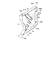
室内ユニット5は、図1に示したように、建物31の天井32と天井板33との間の天井裏空間34内に懸吊して配設され、室内熱交換器(熱交換器)60と、室内熱交換器60に送風する送風ファン50を収容して構成されるユニット本体10と、ユニット本体10から天井板33に延びる吸込みダクト53、及び、吹出ダクト54とを有して構成される。
ユニット本体10のユニットケース11は、天板12、底板13、側板14A,14B、吸込側パネル15、及び、吹出側パネル(前板)16を備え、略矩形に形成される。ユニットケース11は、側板14A,14Bに固定された複数の吊金具41を備える。ユニット本体10は、これらの吊金具41を天井32から垂下された吊ボルト42に止着させて、天井裏空間34内に懸吊される。天井板33には、適宜の位置に、特に、ユニット本体10の真下近傍に、着脱自在の天井パネル35が取り付けられ、この天井パネル35を取り外すことで、被調和室2側から、室内ユニット5の各種メンテナンスを行うことができる。
As shown in FIG. 1, the indoor unit 5 is arranged suspended in a ceiling space 34 between the ceiling 32 and the ceiling plate 33 of the building 31, and an indoor heat exchanger (heat exchanger) 60. And the unit main body 10 configured to accommodate the blower fan 50 for blowing air to the indoor heat exchanger 60, the suction duct 53 extending from the unit main body 10 to the ceiling plate 33, and the blowout duct 54. The
The unit case 11 of the unit body 10 includes a top plate 12, a bottom plate 13, side plates 14A and 14B, a suction side panel 15, and a blowout side panel (front plate) 16, and is formed in a substantially rectangular shape. The unit case 11 includes a plurality of hanging brackets 41 fixed to the side plates 14A and 14B. The unit main body 10 is suspended in the ceiling back space 34 by attaching these suspension fittings 41 to suspension bolts 42 suspended from the ceiling 32. A detachable ceiling panel 35 is attached to the ceiling plate 33 at an appropriate position, particularly near the unit main body 10. By removing the ceiling panel 35, the indoor unit 5 can be connected from the conditioned room 2 side. Various maintenance can be performed.

ユニットケース11は、一対の対向する側面に配置された吸込側パネル15、及び、吹出側パネル16を備え、送風ファン50の上流側に配置された吸込側パネル15に形成された吸込口17と、室内熱交換器60の下流側に配置された吹出側パネル16に形成された吹出口18とを有している。天井板33の適宜位置には、被調和室2内と天井裏空間34とを連通させる吸気口51と、給気口52とが設けられる。ユニットケース11の吸込口17と、天井板33の吸気口51とは、吸込みダクト53で接続される。また、ユニットケース11の吹出口18と、天井板33の給気口52とは、吹出ダクト54で接続される。   The unit case 11 includes a suction side panel 15 disposed on a pair of opposed side surfaces and a blowout side panel 16, and a suction port 17 formed on the suction side panel 15 disposed on the upstream side of the blower fan 50. And an outlet 18 formed in the outlet side panel 16 disposed on the downstream side of the indoor heat exchanger 60. At an appropriate position of the ceiling plate 33, an air inlet 51 and an air supply port 52 are provided that allow the interior of the conditioned room 2 to communicate with the ceiling space 34. The suction port 17 of the unit case 11 and the suction port 51 of the ceiling plate 33 are connected by a suction duct 53. Further, the air outlet 18 of the unit case 11 and the air supply port 52 of the ceiling plate 33 are connected by an air outlet duct 54.

室内ユニット5は、送風ファン50の駆動により、被調和室2内の空気を吸気口51、吸込みダクト53、吸込口17を介してユニット本体10内に吸い込み、吸い込んだ空気を室内熱交換器60に送風して室内熱交換器60内を流れる冷媒と熱交換をさせ、調和空気を、吹出口18、吹出ダクト54、給気口52を介して、被調和室2内に供給する。つまり、室内ユニット5は、被調和室2の空気を吸い込んで、室内熱交換器60内を流れる冷媒と熱交換させた調和空気を再び被調和室2に吹出している。   The indoor unit 5 sucks the air in the conditioned room 2 into the unit main body 10 through the air inlet 51, the air inlet duct 53, and the air inlet 17 by driving the blower fan 50, and the air thus sucked in the indoor heat exchanger 60. Then, heat is exchanged with the refrigerant flowing through the indoor heat exchanger 60, and conditioned air is supplied into the conditioned room 2 through the air outlet 18, the air outlet duct 54, and the air inlet 52. That is, the indoor unit 5 sucks the air in the conditioned room 2 and blows the conditioned air heat-exchanged with the refrigerant flowing in the indoor heat exchanger 60 to the conditioned room 2 again.

図2に示すように、ユニットケース11の、一方側の側面を形成する側板14Aには、メンテナンスパネル56と、ポンプユニット75と、蓋体(配管押さえ)68とが着脱自在に取り付けられている。メンテナンスパネル56は、ユニットケース11内に収容された不図示の電装ユニットのメンテナンスを行うために側板14Aに設けられたメンテナンス用開口を塞ぐように側板14Aに取り付けられる。ポンプユニット75は、後述するドレンパン70からドレン水をくみ上げるドレンポンプ78と、ドレンポンプ78の固定具79とで構成され、側板14Aに設けられたポンプ取付用開口75Aを介してドレンポンプ78をユニットケース11内に収容すると共に、固定具79でこのポンプ取付用開口75Aを塞ぐようにして側板14Aに取り付けられる。蓋体68は、室内熱交換器60に接続され、側板14Aを切欠き68Cを介して貫通する補助冷媒管67を押さえるために配設される。また、側板14Aに蓋体68を取り付けたときには、側板14Aに形成された切欠き68Cを塞ぐように構成されている。   As shown in FIG. 2, a maintenance panel 56, a pump unit 75, and a lid (pipe presser) 68 are detachably attached to the side plate 14 </ b> A that forms one side surface of the unit case 11. . The maintenance panel 56 is attached to the side plate 14A so as to close a maintenance opening provided in the side plate 14A in order to perform maintenance of an electrical unit (not shown) accommodated in the unit case 11. The pump unit 75 includes a drain pump 78 that draws drain water from a drain pan 70, which will be described later, and a fixture 79 of the drain pump 78, and the drain pump 78 is unitized via a pump mounting opening 75A provided in the side plate 14A. While being accommodated in the case 11, the fixture 79 is attached to the side plate 14A so as to close the pump attachment opening 75A. The lid 68 is connected to the indoor heat exchanger 60 and is disposed to hold down the auxiliary refrigerant pipe 67 that penetrates the side plate 14A through the notch 68C. Moreover, when the cover body 68 is attached to the side plate 14A, the cutout 68C formed in the side plate 14A is closed.

このように、ユニットケース11の側板14A側に、電装ユニットと、ドレンポンプ78と、補助冷媒管67と、をまとめて配置したため、ユニット本体10のメンテナンス性を向上することができる。
ポンプユニット75の下方には、側板14Aを下方に開口するように切り欠いたドレン配管用切欠き19が設けられる。このドレン配管用切欠き19には、ドレン配管押さえ76が、ドレン配管用切欠き19に着脱自在に嵌合されて備えられている。ドレン配管押さえ76には、ドレン排水管77が貫通する孔76A(図10参照)が設けられ、後述するドレンパン70に接続されたドレン排水管77は、この孔76Aから突出し配設されている。例えばユニット本体10のメンテナンス時に、ドレンパン70内に残存しているドレン水を排出させるときには、このドレン排水管77を介してドレン水をユニット本体10の外部に排出させることができる。
Thus, since the electrical unit, the drain pump 78, and the auxiliary refrigerant pipe 67 are arranged together on the side plate 14A side of the unit case 11, the maintainability of the unit body 10 can be improved.
Below the pump unit 75, a drain pipe cutout 19 is provided by cutting out the side plate 14A so as to open downward. The drain pipe notch 19 is provided with a drain pipe presser 76 that is detachably fitted to the drain pipe notch 19. The drain pipe retainer 76 is provided with a hole 76A (see FIG. 10) through which the drain drain pipe 77 passes, and a drain drain pipe 77 connected to a drain pan 70 described later protrudes from the hole 76A. For example, when drain water remaining in the drain pan 70 is discharged during maintenance of the unit main body 10, the drain water can be discharged outside the unit main body 10 through the drain drain pipe 77.

吹出側パネル16には、吹出口18の両側方外側に上下に並べてねじ孔69A,69Aが形成されている。天板12には、ねじ孔69Aとユニットケース11のユニット幅W方向の略同じ位置に、ねじ孔69B,69Bが形成されている。これらの各ねじ孔69A,69Bには、詳述については後述するが、室内熱交換器60をユニットケース11に固定するためのねじ4(図5参照)が螺合される。   Screw holes 69 </ b> A and 69 </ b> A are formed in the blowout side panel 16 so as to be vertically arranged on both sides outside the blowout port 18. Screw holes 69B and 69B are formed in the top plate 12 at substantially the same position in the unit width W direction of the screw holes 69A and the unit case 11. As will be described in detail later, the screws 4 (see FIG. 5) for fixing the indoor heat exchanger 60 to the unit case 11 are screwed into the screw holes 69A and 69B.

ユニット本体10内では、吸込口17から吸い込まれた空気は、ユニットケース11の奥行L方向に沿って吹出口18に向かって流れ、室外ユニット間で循環する冷媒は、この空気の流れとは略直行し、ユニットケース11のユニット幅W方向に沿って流れるように構成されている。   In the unit main body 10, the air sucked from the suction port 17 flows toward the blowout port 18 along the depth L direction of the unit case 11, and the refrigerant circulating between the outdoor units is approximately the flow of this air. The unit case 11 is configured to flow straight along the unit width W direction of the unit case 11.

図3に示すように、底板13は、ユニットケース11の奥行L方向に、2分割され、吸込口17側の送風室側底板13Bと、吹出口18側の熱交換室側底板13Aとから構成される。熱交換室側底板13Aには、ユニットケース11の奥行L方向の所定の位置に、ユニットケース11の幅方向(長手方向)に延出する第1ビード71、及び、第2ビード72が形成される。ビード71,72は、第1ビード71のように連続した一本のビードであっても良いし、或いは、第2ビード72のように、複数本に分割して形成されていても良い。底板13は、金属製の薄い板状部材から形成され、ビード71,72は、この板状部材にプレス加工等を施して形成される。各ビード71,72の長さ、形成する位置、及び、形成する数は、底板13の大きさ、形状、厚みに対して適宜に変更可能である。ユニットケース11の奥行Lの寸法は、室内ユニット5の出力によって適宜に変更可能であり、奥行L寸法の小さなユニットケース11では、底板13も短くなり、この場合、例えば、ビード71,72は、同じ長さで、ユニットケース11の幅W方向いっぱいに設けられている構成であっても良い。熱交換室側底板13Aは、ビード71,72を備えるため、強度が向上される。   As shown in FIG. 3, the bottom plate 13 is divided into two in the depth L direction of the unit case 11, and includes a blower chamber side bottom plate 13 </ b> B on the suction port 17 side and a heat exchange chamber side bottom plate 13 </ b> A on the outlet 18 side. Is done. A first bead 71 and a second bead 72 extending in the width direction (longitudinal direction) of the unit case 11 are formed at a predetermined position in the depth L direction of the unit case 11 on the heat exchange chamber side bottom plate 13A. The The beads 71 and 72 may be a single continuous bead like the first bead 71 or may be divided into a plurality of beads like the second bead 72. The bottom plate 13 is formed from a thin plate member made of metal, and the beads 71 and 72 are formed by subjecting this plate member to press working or the like. The length of each bead 71, 72, the position to be formed, and the number to be formed can be appropriately changed with respect to the size, shape, and thickness of the bottom plate 13. The dimension of the depth L of the unit case 11 can be changed as appropriate according to the output of the indoor unit 5. In the unit case 11 having a small depth L dimension, the bottom plate 13 is also shortened. In this case, for example, the beads 71 and 72 are It may be configured to have the same length and be provided all the way in the width W direction of the unit case 11. Since the heat exchange chamber side bottom plate 13A includes the beads 71 and 72, the strength is improved.

図4は、ユニットケース11から、天板12を取り外した図である。ユニットケース11の内部は、図4に示すように、天板12、及び、底板13に略垂直に設けられた仕切板55で、送風ファン50を収容する送風室R1と、室内熱交換器60を収容する熱交換室R2とに区分けされる。仕切板55は金属の板材などで形成される。   FIG. 4 is a diagram in which the top plate 12 is removed from the unit case 11. As shown in FIG. 4, the inside of the unit case 11 is a partition plate 55 provided substantially perpendicular to the top plate 12 and the bottom plate 13, and a blower chamber R <b> 1 that houses the blower fan 50 and an indoor heat exchanger 60. And a heat exchange chamber R2 that accommodates The partition plate 55 is formed of a metal plate material or the like.

送風ファン50には、遠心送風ファンであるシロッコファンが用いられる。送風ファン50は、多数の羽根を備えた筒状のファン本体50Aが、ファンケース50Bに収容され、ファン本体50Aの軸方向に延びるモータ軸50Cが、ファンモータ20に連結され、このファンモータ20の駆動によってファン本体50Aが回転する。送風室R1に収容される送風ファン50の数は、ユニットケース11の寸法(室内ユニット5の出力容量)に合わせて適宜に変更可能である。また、本実施形態では、送風室R1には、複数の送風ファン50が一本のモータ軸50Cによって連結されて備えられ、単一のファンモータ20でこれらの複数の送風ファン50が同様に回転駆動するが、これに限らず、複数の送風ファン50のそれぞれがファンモータ20を備える構成であっても良い。仕切板55には開口55Aが設けられ、送風ファン50の送風口(吹き出し口)50Dは開口55Aに接続されて熱交換室R2側に露出している。   As the blower fan 50, a sirocco fan that is a centrifugal blower fan is used. In the blower fan 50, a cylindrical fan main body 50A having a large number of blades is accommodated in a fan case 50B, and a motor shaft 50C extending in the axial direction of the fan main body 50A is connected to the fan motor 20, and the fan motor 20 The fan main body 50A is rotated by the drive of. The number of the blower fans 50 accommodated in the blower chamber R1 can be appropriately changed according to the dimensions of the unit case 11 (the output capacity of the indoor unit 5). In the present embodiment, the blower chamber R1 is provided with a plurality of blower fans 50 connected by a single motor shaft 50C, and the plurality of blower fans 50 are similarly rotated by the single fan motor 20. However, the present invention is not limited to this, and each of the plurality of blower fans 50 may include the fan motor 20. The partition plate 55 is provided with an opening 55A, and an air blowing port (blowing port) 50D of the blower fan 50 is connected to the opening 55A and exposed to the heat exchange chamber R2.

室内熱交換器60は、図5に示すように、平板状の上側熱交換部61と、下側熱交換部62とを含み、これらの上側熱交換部61と、下側熱交換部62とが、側面視で略くの字状に組み合わせて連結されている。この構成によれば、室内熱交換器60は、平板状の2つの熱交換部61,62を側面視で略くの字状に連結させて構成されているため、平板状の熱交換器を縦置きに配置する場合に比べて、熱交換器の高さを低く抑えて、且つ、熱交換面積を広くすることができる。   As shown in FIG. 5, the indoor heat exchanger 60 includes a flat plate-like upper heat exchange unit 61 and a lower heat exchange unit 62, and these upper heat exchange unit 61, lower heat exchange unit 62, and However, they are connected in a substantially square shape in a side view. According to this configuration, the indoor heat exchanger 60 is configured by connecting the two plate-shaped heat exchange parts 61 and 62 in a substantially square shape in a side view. The height of the heat exchanger can be kept low and the heat exchange area can be increased compared to the case where the heat exchanger is arranged vertically.

上側熱交換部61、下側熱交換部62は、ともに、フィン・アンド・チューブ型の熱交換器であり、通風方向に延びる一対の管板と、管板間に互いに間隔を開けて配置される複数のフィン板と、これらフィン板を貫通する複数のチューブを備えて構成されている。チューブは、前後に複数列(本実施形態では3列)、上下に複数段に並べられて、各チューブの端に設けられたU字部(Uベント)によって1本の冷媒配管として連結されている。   The upper heat exchanging portion 61 and the lower heat exchanging portion 62 are both fin-and-tube heat exchangers, and are arranged with a space between the pair of tube plates extending in the ventilation direction and the tube plates. A plurality of fin plates and a plurality of tubes penetrating the fin plates. The tubes are arranged in a plurality of rows in the front and rear (three rows in the present embodiment) and in a plurality of stages in the vertical direction, and are connected as one refrigerant pipe by a U-shaped portion (U vent) provided at the end of each tube. Yes.

上側熱交換部61は、上端部61Cが天板12の下面傍らまで延在し、下側熱交換部62は、下端部62Cが後述するドレンパン70と当接し、これによって、熱交換室R2は、室内熱交換器60によって、室内熱交換器60の上流側の1次側室65Aと、室内熱交換器60の下流側の2次側室65Bとに区分けされる。また、上側熱交換部61および下側熱交換部62は、同じ幅で形成されて、ユニット幅Wの略一杯に収容されている。   The upper heat exchanging portion 61 has an upper end 61C extending to the side of the lower surface of the top plate 12, and the lower heat exchanging portion 62 is in contact with a drain pan 70 whose lower end 62C will be described later. The indoor heat exchanger 60 divides the primary side chamber 65 </ b> A on the upstream side of the indoor heat exchanger 60 and the secondary side chamber 65 </ b> B on the downstream side of the indoor heat exchanger 60. Further, the upper heat exchanging portion 61 and the lower heat exchanging portion 62 are formed with the same width, and are accommodated almost fully in the unit width W.

上側熱交換部61と、下側熱交換部62とは、下側熱交換部62の1次側室65Aに対向する、空気の流入側面62Aの上に、上側熱交換部61の下端部(下端)61Aが乗り上げ、重ねた状態で配置されている。上側熱交換部61と、下側熱交換部62とは、このように、下側熱交換部62の空気の流入側面62A上に、上側熱交換部61の下端部61Aを重ねて、互いに略直角に、側面視で略くの字状に連結される。つまり、室内熱交換器60のくの字の頂点60Aは、下側熱交換部62の上端部62Bの吹出口18側角部で形成される。また、上側熱交換部61は、下側熱交換部62の上端部62Bよりも送風ファン50側、つまり、1次側室65A側に寄せて配置され、上側熱交換部61の空気の流出側面61Bと、下側熱交換部62の上端部62Bとの間には、段差60Cが形成される。   The upper heat exchanging portion 61 and the lower heat exchanging portion 62 are arranged at the lower end (lower end) of the upper heat exchanging portion 61 on the air inflow side surface 62A facing the primary chamber 65A of the lower heat exchanging portion 62. ) 61A rides and is arranged in a stacked state. In this way, the upper heat exchanging portion 61 and the lower heat exchanging portion 62 overlap each other with the lower end portion 61A of the upper heat exchanging portion 61 on the air inflow side surface 62A of the lower heat exchanging portion 62. They are connected at a right angle in a substantially square shape in side view. In other words, the vertex 60 </ b> A of the cross-section of the indoor heat exchanger 60 is formed by the corner on the outlet 18 side of the upper end 62 </ b> B of the lower heat exchange unit 62. The upper heat exchanging portion 61 is arranged closer to the blower fan 50 side, that is, the primary side chamber 65A side than the upper end portion 62B of the lower heat exchanging portion 62, and the air outflow side surface 61B of the upper heat exchanging portion 61 is disposed. And a step 60 </ b> C is formed between the upper end 62 </ b> B of the lower heat exchange unit 62.

上側熱交換部61で発生し、自重で流出側面61Bを伝って流れる結露水等のドレン水は、上側熱交換部61の空気の流出側面61Bと、下側熱交換部62の上端部62Bとの間に形成された段差60Cで受け止められて、下側熱交換部62の表面を伝って流れる。これにより、上側熱交換部61で発生したドレン水が、上側熱交換部61と、下側熱交換部62との連結部60Bから飛散するのを防止することができる。   Drain water, such as condensed water, that is generated in the upper heat exchange unit 61 and flows along the outflow side surface 61B under its own weight, flows out from the air outflow side surface 61B of the upper heat exchange unit 61 and the upper end portion 62B of the lower heat exchange unit 62. It is received by the step 60 </ b> C formed between and flows along the surface of the lower heat exchange unit 62. Thereby, it is possible to prevent the drain water generated in the upper heat exchange part 61 from being scattered from the connecting part 60 </ b> B between the upper heat exchange part 61 and the lower heat exchange part 62.

送風ファン50は、送風口50Dからの吹き出し方向が上側熱交換部61と、下側熱交換部62との連結部60Bに向かうように、送風口50Dが斜め下向きに設けられるように配置される。室内熱交換器60は、上側熱交換部61のチューブ段数が6段に構成され、下側熱交換部62のチューブ段数が10段に構成される。つまり、上側熱交換部61と、下側熱交換部62とは、同じ厚さ、同じ幅で形成され、かつ、下側熱交換部62の熱交換面積が、上側熱交換部61の熱交換面積よりも大きく形成されている。これにより、送風ファン50の吹出し方向が下向きで、かつ、下側熱交換部62の熱交換面積が大きく形成されているため、上側熱交換部61と、下側熱交換部62とを通る空気の量をそれぞれ略同じにすることができ、上側熱交換部61と、下側熱交換部62との熱交換面内での温度差を小さくして、室内熱交換器60内での熱交換効率の均一化を図ることができる。   The blower fan 50 is arranged so that the blower port 50D is provided obliquely downward so that the blowing direction from the blower port 50D is directed to the connecting part 60B between the upper heat exchange unit 61 and the lower heat exchange unit 62. . In the indoor heat exchanger 60, the number of tube stages of the upper heat exchange unit 61 is configured to be six, and the number of tube stages of the lower heat exchange unit 62 is configured to be ten. That is, the upper heat exchange unit 61 and the lower heat exchange unit 62 are formed with the same thickness and the same width, and the heat exchange area of the lower heat exchange unit 62 is the heat exchange of the upper heat exchange unit 61. It is formed larger than the area. Thereby, since the blowing direction of the blower fan 50 is downward and the heat exchange area of the lower heat exchange part 62 is large, the air passing through the upper heat exchange part 61 and the lower heat exchange part 62 The amount of heat can be made substantially the same, the temperature difference in the heat exchange surface between the upper heat exchange unit 61 and the lower heat exchange unit 62 is reduced, and heat exchange in the indoor heat exchanger 60 is performed. Efficiency can be made uniform.

室内熱交換器60は、くの字の開放側が図4に示したように、送風ファン50の送風口50Dに対向する向きで配置される構成であっても良いし、或いは、図示は省略したが、くの字の頂点側が送風ファン50の送風口50Dに対向する向きで配置される構成であっても良い。熱交換器60は、下側熱交換部62の水平方向に対する傾きαが37度より小さくならないように配置される。下側熱交換部62の水平方向に対する傾き角度を37度以上とすることにより、ドレン水が下側熱交換部62を伝って流れにくくなるのを防止することができ、熱交換器60の熱交換能力がドレン水の付着により低下するのを防止することができる。   As shown in FIG. 4, the indoor heat exchanger 60 may have a configuration in which the open side of the character is disposed in a direction facing the blower opening 50D of the blower fan 50, or the illustration is omitted. However, the structure arrange | positioned in the direction which opposes the ventilation port 50D of the ventilation fan 50 may be sufficient as the vertex side of a character-shape. The heat exchanger 60 is arranged so that the inclination α of the lower heat exchange part 62 with respect to the horizontal direction does not become smaller than 37 degrees. By setting the inclination angle of the lower heat exchange part 62 with respect to the horizontal direction to 37 degrees or more, it is possible to prevent the drain water from flowing through the lower heat exchange part 62 and the heat of the heat exchanger 60. It is possible to prevent the exchange capacity from being lowered due to adhesion of drain water.

室内熱交換器60の下方には、室内熱交換器60のドレン水を受けるドレンパン70が配置される。ドレンパン70は、熱交換室R2の底面一杯を覆い、底板13に支持される。ドレンパン70は、発砲スチロール製であり、室内熱交換器60のドレン水を受ける内側は防水、防カビのために、樹脂シート等で覆われる。これにより、ドレンパン70を軽量化することができる。ドレンパン70には、底部が一段低くなったドレン溜まり70Aが形成され、このドレン溜まり70Aには、図示は省略したが、ドレンポンプ78の吸込み口が配置されている。   A drain pan 70 that receives drain water from the indoor heat exchanger 60 is disposed below the indoor heat exchanger 60. The drain pan 70 covers the entire bottom surface of the heat exchange chamber R2 and is supported by the bottom plate 13. The drain pan 70 is made of foamed polystyrene, and the inside of the indoor heat exchanger 60 that receives the drain water is covered with a resin sheet or the like for waterproofing and mold prevention. Thereby, the drain pan 70 can be reduced in weight. The drain pan 70 is formed with a drain reservoir 70A whose bottom is lowered by one step, and the drain reservoir 70A is provided with a suction port of a drain pump 78, although not shown.

また、ドレンパン70には、下側熱交換部62の下端部62Cが当接する当接部73が形成される。この当接部73には、図示は省略したが、緩衝材がドレンパン70の幅方向に略一杯に延在している構成であっても良い。
底板13は、送風室R1側の底面を覆う送風室側底板13Bと、熱交換室R2側の底面を覆う熱交換室側底板13Aとに分割されている。ドレンパン70は、熱交換室側底板13Aを取り外すことで、ユニットケース11から着脱自在に備えられる。ドレンパン70は、4側面が底面に対して立ち上がった箱形状に形成される。仕切板55、及び、吹出側パネル16の熱交換室R2側の面には、ドレンパン70の側面上端が当接する位置決め板74Aがユニットケース11の幅方向に所定間隔を空けて複数設けられている。つまり、ドレンパン70は、位置決め板74A,75と、熱交換室側底板13Aとの間に挟まれた状態で保持される。このように、ドレンパン70は、熱交換室側底板13Aに支持されてユニットケース11内に収容されるため、熱交換室側底板13Aを取り外して、ユニットケース11の底面側から容易に脱着させることができる。
Further, the drain pan 70 is formed with an abutting portion 73 with which the lower end portion 62C of the lower heat exchanging portion 62 abuts. Although not shown in the drawing, the contact portion 73 may have a configuration in which the cushioning material extends substantially fully in the width direction of the drain pan 70.
The bottom plate 13 is divided into a blower chamber side bottom plate 13B that covers the bottom surface on the blower chamber R1 side, and a heat exchange chamber side bottom plate 13A that covers the bottom surface on the heat exchange chamber R2 side. The drain pan 70 is detachably provided from the unit case 11 by removing the heat exchange chamber side bottom plate 13A. The drain pan 70 is formed in a box shape with four side surfaces rising from the bottom surface. A plurality of positioning plates 74 </ b> A with which the upper end of the side surface of the drain pan 70 abuts are provided at predetermined intervals in the width direction of the unit case 11 on the surface of the partition plate 55 and the heat exchange chamber R <b> 2 side of the blowout side panel 16. . That is, the drain pan 70 is held in a state of being sandwiched between the positioning plates 74A and 75 and the heat exchange chamber side bottom plate 13A. Thus, since the drain pan 70 is supported by the heat exchange chamber side bottom plate 13A and accommodated in the unit case 11, the heat exchange chamber side bottom plate 13A can be removed and easily detached from the bottom surface side of the unit case 11. Can do.

熱交換室側底板13Aには、図6に示したように、上述したビード71,72が形成されている。ビード71,72は、仕切板55と熱交換器60との間の1次側室65Aの下方に位置する。第1ビード71は、下側熱交換部62の下端部62Cと、ドレンパン70とが当接する当接部73の下方に位置する。つまり、ユニットケース11に室内熱交換器60、ドレンパン70、及び、熱交換室側底板13Aを取り付けた状態で、下側熱交換部62の下端部62Cと、ドレンパン70と、が当接する当接部73、及び、熱交換室側底板13Aの第1ビード71が、上下方向に並ぶように構成されている。
第2ビード72は、ドレンパン70の側面上端70Aと、仕切板55に取り付けられた位置決め板74Aと、が当接する位置の下方に設けられる。つまり、ユニットケース11にドレンパン70と、熱交換室側底板13Aとを取り付けた状態で、仕切板55に取り付けられた位置決め板74Aと、ドレンパン70の側面上端70Aと、が当接する当接部、及び、第2ビード72と、上下方向に並ぶように構成されている。
As shown in FIG. 6, the beads 71 and 72 described above are formed on the heat exchange chamber side bottom plate 13 </ b> A. The beads 71 and 72 are located below the primary side chamber 65 </ b> A between the partition plate 55 and the heat exchanger 60. The first bead 71 is positioned below the contact portion 73 where the lower end portion 62C of the lower heat exchange portion 62 and the drain pan 70 contact. In other words, in a state where the indoor heat exchanger 60, the drain pan 70, and the heat exchange chamber side bottom plate 13A are attached to the unit case 11, the lower end 62C of the lower heat exchange unit 62 and the drain pan 70 come into contact with each other. The part 73 and the first bead 71 of the heat exchange chamber side bottom plate 13A are arranged in the vertical direction.
The second bead 72 is provided below the position where the side surface upper end 70 </ b> A of the drain pan 70 contacts the positioning plate 74 </ b> A attached to the partition plate 55. That is, the contact portion where the positioning plate 74A attached to the partition plate 55 and the side surface upper end 70A of the drain pan 70 abut with the drain pan 70 and the heat exchange chamber side bottom plate 13A attached to the unit case 11. In addition, the second bead 72 is arranged in the vertical direction.

仕切板55は、上側仕切板55Bと、下側仕切板55Cとから構成される。下側仕切板55Cは、一枚の板が略L字状に折り曲げられて、上側仕切板55Bに接着される接続部74Bと、ユニットケース11の底面の一部を形成する底板部74Cと、を一体に備えるように形成される、備える。また、下側仕切板55Cには、位置決め板74Aが一体に形成されている。位置決め板74Aは、接続部74Bの上部に、ユニットケース11の幅方向に所定間隔を空けて複数設けられた延出部位を、接続部74Bに対して略直角に、底板部74Cとは逆方向に折り曲げて形成される。   The partition plate 55 includes an upper partition plate 55B and a lower partition plate 55C. The lower partition plate 55C includes a connection portion 74B that is bonded to the upper partition plate 55B by bending a single plate into a substantially L shape, and a bottom plate portion 74C that forms part of the bottom surface of the unit case 11. Are formed so as to be integrally provided. A positioning plate 74A is integrally formed with the lower partition plate 55C. The positioning plate 74A has a plurality of extended portions provided at a predetermined interval in the width direction of the unit case 11 at the upper part of the connection portion 74B, substantially perpendicular to the connection portion 74B and in the direction opposite to the bottom plate portion 74C. It is formed by bending it.

熱交換室側底板13Aは、ユニットケース11の奥行L方向の一方側が、仕切板55よりも送風室R1側に延出している。熱交換室側底板13Aは、この一方側が底面側から下側仕切板55Cの底板部74Cに、ユニットケース11の幅方向に所定間隔を空けて複数箇所、ねじ3でねじ留めされて固定される。
前板16は、断面視略コ字状に上下をユニットケース11の内側に折り曲げて、天部16A、及び、底部16Bが形成される。底部16Bには、熱交換室側底板13Aの他方側が、底面側からユニットケース11の幅方向に所定間隔を空けて複数箇所、ねじ3でねじ留めされて固定される。このように、熱交換室側底板13Aは、ユニットケース11の底面側から底部16B、及び、底板部74Cに、幅方向の両端部を押し当てた状態で、ねじ3でねじ留めされているため、天井パネル35を取り外した被調和室2側からでも容易に取り外すことができ、熱交換室R2のメンテナンス性を向上することができる。
天部16Aには、天板12がねじで固定されて、室内熱交換器60の上端60Dと、天板12との間には、2次側室65の上面を覆う発泡材等によって形成された断熱材21が取り付けられる。
In the heat exchange chamber side bottom plate 13A, one side in the depth L direction of the unit case 11 extends from the partition plate 55 to the air blowing chamber R1 side. The one side of the heat exchange chamber side bottom plate 13A is fixed to the bottom plate portion 74C of the lower partition plate 55C from the bottom surface side with a plurality of screws 3 at predetermined intervals in the width direction of the unit case 11. .
The front plate 16 is bent in the upper and lower sides in the unit case 11 in a substantially U shape in a sectional view to form a top portion 16A and a bottom portion 16B. On the bottom portion 16B, the other side of the heat exchange chamber side bottom plate 13A is fixed by being screwed with a plurality of screws 3 at a predetermined interval in the width direction of the unit case 11 from the bottom surface side. As described above, the heat exchange chamber side bottom plate 13A is screwed with the screw 3 in a state where both end portions in the width direction are pressed against the bottom portion 16B and the bottom plate portion 74C from the bottom surface side of the unit case 11. Moreover, it can be easily removed from the conditioned room 2 side from which the ceiling panel 35 is removed, and the maintainability of the heat exchange chamber R2 can be improved.
The top plate 12 is fixed to the top portion 16A with screws, and formed between the upper end 60D of the indoor heat exchanger 60 and the top plate 12 by a foam material or the like covering the upper surface of the secondary side chamber 65. A heat insulating material 21 is attached.

ところで、熱交換室R2内では、室内熱交換器60が通風抵抗となるため、1次側室65A内で静圧が高くなる。この1次側室65Aで、ドレンパン70は、下側熱交換部62の下端部62Cと第1ビード71の間、及び、位置決め板74Aと第2ビード72の間に挟持される。これによって、ビード71,72は、ドレンパン70を補助的に固定する役割をはたし、簡単な構成で、ドレンパン70が1次側室65A側の静圧によって浮き上がるのを防止することができる。   By the way, in the heat exchange chamber R2, since the indoor heat exchanger 60 becomes ventilation resistance, a static pressure becomes high in the primary side chamber 65A. In the primary chamber 65A, the drain pan 70 is sandwiched between the lower end 62C of the lower heat exchange unit 62 and the first bead 71, and between the positioning plate 74A and the second bead 72. As a result, the beads 71 and 72 play a role of auxiliaryly fixing the drain pan 70 and can prevent the drain pan 70 from being lifted by the static pressure on the primary side chamber 65A side with a simple configuration.

室内熱交換器60の幅方向の両幅端部には、図7に示すように、一端側固定部材63Aと、他端側固定部材63Bがそれぞれ取り付けられている。固定部材63A,63Bは、樹脂により成形され、固定部材63A,63B間に室内熱交換器60を挟み込みようにして、室内熱交換器60と一体に固定される。
室内熱交換器60の一端部には、一端側固定部材63Aが固定される。室内熱交換器60の一端部には、この一端部に取り付けられた管板と一体に形成され、上側熱交換部61の上端部61Cと、上側熱交換部61及び下側熱交換部62の空気の流出側面61B,62Aとへ延出する固定部8が設けられる(図6参照)。一端側固定部材63Aは、この固定部8に、ねじ8aで螺合されて、室内熱交換器60に固定される。
As shown in FIG. 7, one end side fixing member 63A and the other end side fixing member 63B are attached to both width end portions in the width direction of the indoor heat exchanger 60, respectively. The fixing members 63A and 63B are molded of resin, and are fixed integrally with the indoor heat exchanger 60 so that the indoor heat exchanger 60 is sandwiched between the fixing members 63A and 63B.
One end side fixing member 63 </ b> A is fixed to one end portion of the indoor heat exchanger 60. One end portion of the indoor heat exchanger 60 is formed integrally with a tube plate attached to the one end portion, and the upper end portion 61C of the upper heat exchange portion 61, the upper heat exchange portion 61, and the lower heat exchange portion 62. A fixing portion 8 extending to the air outflow side surfaces 61B and 62A is provided (see FIG. 6). The one end side fixing member 63A is screwed to the fixing portion 8 with a screw 8a and fixed to the indoor heat exchanger 60.

図8は、一端側固定部材63Aを、図7中に示した矢印方向から視た図である。一端側固定部材63Aには、図8に示すように、室内熱交換器60の管板から突出するUベントが挿入される複数のベント孔81が形成される。各ベント孔81は、管板から突出するUベントの位置に対応付けて形成され、一端側固定部材63Aは、各ベント孔81にUベントを挿入することで、位置決めされて、上述したように固定部8をねじ留めすることで、簡単に室内熱交換器60に取り付けることができる。ベント孔81には、外周に沿って周壁81Aが形成される。周壁81Aは、ベント孔81に挿入されるUベントの高さと略同じ高さに形成される。また、一端側固定部材63Aの幅W2は、ベント孔81に挿入されるUベントの高さと略同じに形成される。周壁81A、及び、一端側固定部材63Aにより、管板から突出するUベントの周囲を囲み、室内熱交換器60をユニットケース11から着脱する際に、Uベントが他の部材にぶつかるのを防ぐことができる。また、各ベント孔81にUベントを挿入することで、一端側固定部材63Aを室内熱交換器60に対して、位置決め、及び、仮固定することができ、固定部材63を容易に室内熱交換器60に一体に固定することができる。   FIG. 8 is a view of the one-end-side fixing member 63A viewed from the direction of the arrow shown in FIG. As shown in FIG. 8, the one end side fixing member 63A is formed with a plurality of vent holes 81 into which U vents protruding from the tube plate of the indoor heat exchanger 60 are inserted. Each vent hole 81 is formed in correspondence with the position of the U vent protruding from the tube plate, and the one end side fixing member 63A is positioned by inserting the U vent into each vent hole 81, as described above. By screwing the fixing portion 8, it can be easily attached to the indoor heat exchanger 60. A peripheral wall 81A is formed in the vent hole 81 along the outer periphery. The peripheral wall 81A is formed at substantially the same height as the height of the U vent inserted into the vent hole 81. Further, the width W2 of the one end side fixing member 63A is formed to be substantially the same as the height of the U vent inserted into the vent hole 81. The peripheral wall 81A and the one end side fixing member 63A surround the periphery of the U vent protruding from the tube sheet, and prevent the U vent from colliding with other members when the indoor heat exchanger 60 is attached to and detached from the unit case 11. be able to. Further, by inserting a U vent into each vent hole 81, the one end side fixing member 63A can be positioned and temporarily fixed with respect to the indoor heat exchanger 60, and the fixing member 63 can be easily exchanged with the indoor heat. It can be fixed to the vessel 60 integrally.

室内熱交換器60の他端側には、図7に示すように、他端側固定部材63Bが取り付けられる。他端側固定部材63Bからは、室内熱交換器60を、ガス管、及び、液管に接続するための補助冷媒管67が延出している。補助冷媒管67は、ガス管への接続用であるガス管用補助冷媒管67Aと、液管への接続用である液管用補助冷媒管67Bとから構成される。補助冷媒管67は、他端側固定部材63B側にまとめられており、室内熱交換器60から一端側固定部材63Aの外側には突出する部材が無いように構成されている。   As shown in FIG. 7, the other end side fixing member 63 </ b> B is attached to the other end side of the indoor heat exchanger 60. An auxiliary refrigerant pipe 67 for connecting the indoor heat exchanger 60 to the gas pipe and the liquid pipe extends from the other end side fixing member 63B. The auxiliary refrigerant pipe 67 includes a gas pipe auxiliary refrigerant pipe 67A for connection to the gas pipe and a liquid pipe auxiliary refrigerant pipe 67B for connection to the liquid pipe. The auxiliary refrigerant pipe 67 is gathered on the other end side fixing member 63B side, and is configured such that no member protrudes from the indoor heat exchanger 60 to the outside of the one end side fixing member 63A.

他端側固定部材63Bは、図9(A)、図9(B)に示すように、上側熱交換部61及び下側熱交換部62の空気の流出側面61B,62Aに沿って、略くの字に形成された溝25を有する。溝25には、凹部26が形成され、凹部26には、管板9を固定するねじ7が螺合されるねじ孔26Aが設けられる。他端側固定部材63Bは、上側熱交換部61及び下側熱交換部62の空気の流出側面61B,62Aに溝25を沿うようにして、室内熱交換器60の2次側から管板9に固定される。管板9には、管板9に一体に形成され、管板9から延出する板材9Aを備える。板材9Aは、溝25に形成された凹部26に挿入される。板材9Aと、凹部26とは、ねじ7で螺合されて、他端側固定部材63Bが、室内熱交換器60と一体に固定される。このように、他端側固定部材63Bは、室内熱交換器60の2次側に管板9に沿って溝25を備えるため、室内熱交換器60に接続される補助冷媒管67に干渉することなく取り付けることができる。
このようにして、室内熱交換器60と、固定部材63A,63Bと、補助冷媒管67とは、室内熱交換ユニット80として一体化され、室内熱交換ユニット80は、ユニットケース11に一体に着脱自在に取付けられる。
The other end side fixing member 63B is substantially along the air outflow side surfaces 61B and 62A of the upper heat exchanging portion 61 and the lower heat exchanging portion 62, as shown in FIGS. 9A and 9B. It has the groove | channel 25 formed in the character. A recess 26 is formed in the groove 25, and a screw hole 26 </ b> A into which the screw 7 for fixing the tube plate 9 is screwed is provided in the recess 26. The other end side fixing member 63 </ b> B extends from the secondary side of the indoor heat exchanger 60 to the tube plate 9 along the groove 25 along the air outflow side surfaces 61 </ b> B and 62 </ b> A of the upper heat exchange unit 61 and the lower heat exchange unit 62. Fixed to. The tube plate 9 includes a plate material 9 </ b> A that is integrally formed with the tube plate 9 and extends from the tube plate 9. The plate material 9 </ b> A is inserted into the recess 26 formed in the groove 25. The plate member 9 </ b> A and the recess 26 are screwed together with the screws 7, and the other end side fixing member 63 </ b> B is fixed integrally with the indoor heat exchanger 60. Thus, since the other end side fixing member 63B includes the groove 25 along the tube plate 9 on the secondary side of the indoor heat exchanger 60, it interferes with the auxiliary refrigerant pipe 67 connected to the indoor heat exchanger 60. Can be installed without
In this way, the indoor heat exchanger 60, the fixing members 63A and 63B, and the auxiliary refrigerant pipe 67 are integrated as an indoor heat exchange unit 80, and the indoor heat exchange unit 80 is integrally attached to and detached from the unit case 11. Can be installed freely.

固定部材63A,63Bには、図7、図8、図9に示すように、室内熱交換ユニット80をユニットケース11にねじで固定するためのねじ孔64A,64Bが形成されている。ねじ孔64Aは、ユニットケース11の天板12に形成されたねじ孔69Bに対応する位置に設けられ、これらのねじ孔69B、及び、ねじ孔64Aをねじで螺合して、室内熱交換ユニット80は、ユニットケース11の天板12に固定される。ねじ孔64Aは、一端側固定部材63Aに設けられたように、一端側固定部材63Aに一体に形成されていても良いし、或いは、他端側固定部材63Bに設けられたように、他端側固定部材63Bに一体に固定される金属製のブラケット等に形成されていても良い。固定部材63A,63Bには、ねじ孔64Bが内部に形成されるボス部64Cが備えられ、ボス部64Cの内側には、ねじ孔64Aを介してねじが螺合されるねじ山がきられている。   As shown in FIGS. 7, 8, and 9, screw holes 64 </ b> A and 64 </ b> B for fixing the indoor heat exchange unit 80 to the unit case 11 with screws are formed in the fixing members 63 </ b> A and 63 </ b> B. The screw hole 64A is provided at a position corresponding to the screw hole 69B formed in the top plate 12 of the unit case 11, and the screw hole 69B and the screw hole 64A are screwed together with a screw, so that the indoor heat exchange unit 80 is fixed to the top plate 12 of the unit case 11. The screw hole 64A may be formed integrally with the one end side fixing member 63A as provided in the one end side fixing member 63A, or the other end as provided in the other end side fixing member 63B. You may form in the metal bracket etc. which are integrally fixed to the side fixing member 63B. The fixing members 63A and 63B are provided with a boss portion 64C in which a screw hole 64B is formed, and a screw thread into which a screw is screwed through the screw hole 64A is formed inside the boss portion 64C. .

ねじ孔64Bは、ユニットケース11の吹出側パネル16に形成されたねじ孔69Aに対応する位置に設けられる。ねじ孔69Aは、室内熱交換器60と略同じ幅に形成された吹出口18の近傍に上下に並べて複数設けられ、これらのねじ孔69A、及び、ねじ孔64Bをねじで螺合して、室内熱交換ユニット80は、ユニットケース11の吹出側パネル16に固定される。
このように固定部材63A,63Bは、熱交換室R2において、室内熱交換器60の両側面側から、室内熱交換器60の上流側の1次側室65Aと、2次側室65Bとを仕切る役割を果たす。また、固定部材63A,63Bは、断熱性に優れた樹脂材により形成されるため、固定部材63A,63Bには、断熱材を貼りつけることなく、2次側室65Bと、1次側室65Aとを断熱することができる。
The screw hole 64 </ b> B is provided at a position corresponding to the screw hole 69 </ b> A formed in the outlet side panel 16 of the unit case 11. A plurality of screw holes 69A are provided in the vicinity of the air outlet 18 formed in substantially the same width as the indoor heat exchanger 60. The screw holes 69A and the screw holes 64B are screwed together with screws, The indoor heat exchange unit 80 is fixed to the blow-out side panel 16 of the unit case 11.
Thus, the fixing members 63A and 63B function to partition the primary side chamber 65A upstream of the indoor heat exchanger 60 and the secondary side chamber 65B from both side surfaces of the indoor heat exchanger 60 in the heat exchange chamber R2. Fulfill. In addition, since the fixing members 63A and 63B are formed of a resin material having excellent heat insulation properties, the secondary side chamber 65B and the primary side chamber 65A are formed on the fixing members 63A and 63B without attaching the heat insulating material. Can be insulated.

室内熱交換ユニット80は、幅方向の両側端部に取り付けた固定部材63A,63Bに設けたねじ孔64A,64Bを用いて、天板12、と、吹出側パネル16とに固定されて、ユニット本体10の内側に固定することができる。これにより、固定部材63A,63Bは、室内熱交換器60の両側面側で1次側室65Aと2次側室65Bとを仕切る役割を果たすとともに、室内熱交換器60をユニット本体10内に固定する役割を果たすため、例えば、仕切板55に室内熱交換器60を固定するための固定具を設けて、室内熱交換器60をユニット本体10の内側に固定する場合にくらべて、部品点数の削減と、取付作業性の向上を図ることができる。また、室内熱交換器60から送風ファン50側への固定具の飛び出しがなく、熱交換室R2の1次側室65Aでの通風抵抗を低減させることができる。   The indoor heat exchange unit 80 is fixed to the top plate 12 and the blowout side panel 16 using screw holes 64A and 64B provided in fixing members 63A and 63B attached to both end portions in the width direction. It can be fixed inside the main body 10. Thus, the fixing members 63A and 63B serve to partition the primary side chamber 65A and the secondary side chamber 65B on both side surfaces of the indoor heat exchanger 60, and fix the indoor heat exchanger 60 in the unit body 10. In order to fulfill the role, for example, a fixture for fixing the indoor heat exchanger 60 to the partition plate 55 is provided, and the number of parts is reduced as compared with the case where the indoor heat exchanger 60 is fixed inside the unit body 10. And improvement of workability | operativity can be aimed at. Moreover, there is no protrusion of the fixture from the indoor heat exchanger 60 to the blower fan 50 side, and the ventilation resistance in the primary side chamber 65A of the heat exchange chamber R2 can be reduced.

また、室内熱交換器60の一端側に取り付けられる一端側固定部材63Aに、管板から突出するUベントが挿入されるベント孔81を設け、室内熱交換器60の他端側に取り付けられる他端側固定部材63Bは、管板9の2次側形状に沿った形状に形成された溝25を備えるため、室内熱交換器60の両端から外側に突出する部材と干渉することなく、室内熱交換器60を両端側から挟み込むようにして固定部材63A,63Bを取り付けることができる。このように、互いに異なる形状に形成された一対の固定部材63A,63Bとを用いて、室内熱交換器60を、室内熱交換器60に接続される補助冷媒管67と一体にユニット本体10内に着脱自在に備えることができ、室内熱交換器60のメンテナンス性が向上する。室内熱交換ユニット80は、詳細については後述するが、図10に示した下方開口部40から熱交換室R2内に挿入可能に備えられる。   In addition, the one end side fixing member 63A attached to one end side of the indoor heat exchanger 60 is provided with a vent hole 81 into which a U vent protruding from the tube plate is inserted, and is attached to the other end side of the indoor heat exchanger 60. Since the end-side fixing member 63B includes the groove 25 formed in a shape along the secondary side shape of the tube sheet 9, the end-side fixing member 63B does not interfere with members protruding outward from both ends of the indoor heat exchanger 60, and the indoor heat The fixing members 63A and 63B can be attached so as to sandwich the exchanger 60 from both ends. As described above, the indoor heat exchanger 60 is integrated with the auxiliary refrigerant pipe 67 connected to the indoor heat exchanger 60 in the unit main body 10 using the pair of fixing members 63A and 63B formed in different shapes. The maintenance of the indoor heat exchanger 60 is improved. Although details will be described later, the indoor heat exchange unit 80 is provided so as to be inserted into the heat exchange chamber R2 from the lower opening 40 shown in FIG.

図10は、熱交換室側底板13A、及び、ドレンパン70を取り外した状態のユニット本体10を斜め下側から視た図である。このようにユニットケース11の下面には、熱交換室側底板13A、及び、ドレンパン70を取り外すことで、熱交換室R2の底全体に亘る下方開口部(開口部)81が形成される。
側板14Aには、蓋体(配管おさえ)68と、ドレンポンプを固定する固定具79と、内部に収容される電装ユニット用のメンテナンスパネル56とが、それぞれ別体に形成されて、着脱自在に取り付けられている。図10は、説明の便宜上、蓋体68をユニットケース11から取り外している状態を示している。
FIG. 10 is a view of the unit main body 10 with the heat exchange chamber side bottom plate 13 </ b> A and the drain pan 70 removed, as viewed obliquely from below. Thus, the lower opening (opening) 81 over the whole bottom of the heat exchange chamber R2 is formed on the lower surface of the unit case 11 by removing the heat exchange chamber side bottom plate 13A and the drain pan 70.
On the side plate 14A, a lid body (pipe presser) 68, a fixture 79 for fixing the drain pump, and a maintenance panel 56 for the electrical unit housed inside are formed separately and are detachable. It is attached. FIG. 10 shows a state where the lid 68 is removed from the unit case 11 for convenience of explanation.

ユニットケース11の側板14Aには、蓋体68が取り付けられる切欠き68Cが設けられる。切欠き68Cは、ユニットケース11の下方に開口し、下方開口部40と連通するように形成される。室内熱交換器60から側板14Aの外方に突出する補助冷媒管67は、この切欠き68Cを介して、室内熱交換器60と一体に下方開口部40から熱交換室R2内に挿入される。側板14Aには、切欠き68Cに、補助冷媒配管が挿入可能に下方を開口する逆U字溝66A,66Bを備えている。つまり、切欠き68Cは、各逆U字溝66A,66Bが補助冷媒管67に対応する位置に配置されるように形成されている。   The side plate 14A of the unit case 11 is provided with a notch 68C to which the lid 68 is attached. The notch 68 </ b> C is formed to open below the unit case 11 and communicate with the lower opening 40. The auxiliary refrigerant pipe 67 protruding outward from the side plate 14A from the indoor heat exchanger 60 is inserted into the heat exchange chamber R2 from the lower opening 40 integrally with the indoor heat exchanger 60 through the notch 68C. . The side plate 14A is provided with inverted U-shaped grooves 66A and 66B that open downward in a notch 68C so that auxiliary refrigerant piping can be inserted. That is, the notch 68 </ b> C is formed such that each inverted U-shaped groove 66 </ b> A, 66 </ b> B is disposed at a position corresponding to the auxiliary refrigerant pipe 67.

蓋体68は、この逆U字溝66A,66Bに対応する位置に設けられた上方に開口するU字溝68A,68Bを備える。蓋体68は、側板14Aの切欠き68Cを塞ぎ、蓋体68の下部に設けられたねじ孔68D,68Dに挿入される不図字のねじで、側板14Aに固定される。蓋体68には、ねじ孔68D,68Dの上方に、蓋体68の長さ寸法L2に亘る取っ手68Eが形成され、この取っ手68Eを手で押さえて、蓋体68を側板14Aから着脱させることができる。側板14Aに蓋体68を取り付けたときには、蓋体68のU字溝68A,68Bと、側板14Aの逆U字溝66A,66Bとの協働により、補助冷媒管67が側板14Aに保持される。   The lid body 68 is provided with U-shaped grooves 68A and 68B opened upward at positions corresponding to the inverted U-shaped grooves 66A and 66B. The lid 68 is fixed to the side plate 14 </ b> A with unillustrated screws that close the notches 68 </ b> C of the side plate 14 </ b> A and are inserted into screw holes 68 </ b> D and 68 </ b> D provided in the lower portion of the lid 68. The lid 68 is formed with a handle 68E extending over the length L2 of the lid 68 above the screw holes 68D and 68D. The handle 68E is pressed by the hand to detach the lid 68 from the side plate 14A. Can do. When the lid 68 is attached to the side plate 14A, the auxiliary refrigerant pipe 67 is held on the side plate 14A by the cooperation of the U-shaped grooves 68A and 68B of the lid 68 and the reverse U-shaped grooves 66A and 66B of the side plate 14A. .

また、蓋体68には、U字溝68Bと、取っ手68Eの間に注水用開口85形成される。注水用開口85は、通常は、蓋体68にねじ等で固定される蓋86で閉封されている。ユニット本体10の取り付け時等、ユニット本体10内でのドレン水の流れを確認する際には、この注水用開口85から蓋86を取り外し、注水用開口85を介して熱交換室R2内に注水を行ってドレン水の流れを確認する。   Further, a water injection opening 85 is formed in the lid 68 between the U-shaped groove 68B and the handle 68E. The water injection opening 85 is normally closed with a lid 86 fixed to the lid body 68 with a screw or the like. When confirming the flow of drain water in the unit main body 10 such as when the unit main body 10 is attached, the lid 86 is removed from the water injection opening 85 and water is injected into the heat exchange chamber R2 through the water injection opening 85. To confirm the flow of drain water.

蓋体68は、ユニットケース11の側板14Aにねじ等によって固定され、これらのねじを取り外して、ユニットケース11から下方に取り外すことができる。蓋体68を側板14Aから取り外すことで、切欠き68Cは、下方開口部40と連通する。これにより、ユニットケース11には、室内熱交換ユニット80から補助冷媒管67を取り外すことなく室内熱交換ユニット80をユニットケース11から下方に引き出して取り外すことができるように底面側が開放される。   The lid body 68 is fixed to the side plate 14A of the unit case 11 with screws or the like, and can be removed downward from the unit case 11 by removing these screws. The notch 68C communicates with the lower opening 40 by removing the lid 68 from the side plate 14A. Thereby, the bottom side of the unit case 11 is opened so that the indoor heat exchange unit 80 can be pulled out and removed from the unit case 11 without removing the auxiliary refrigerant pipe 67 from the indoor heat exchange unit 80.

室内熱交換ユニット80を取り外す際には、まず、ビルトイン型空気調和装置1のポンプダウン運転を行い、図示は省略したが、室外ユニット、或いは、冷媒回収機に室内熱交換器60内の冷媒を全て回収して、バルブを閉じ、室内熱交換器60を冷媒回路から断絶する。次に、天井パネル35を取り外した天井板33の開口を介して、ユニットケース11から、熱交換室側底板13A、ドレンパン70、及び、配管押さえ68を取り外して、ユニットケース11の下部に室内熱交換ユニット80を下方に取り外すための開口を設ける。
ドレンパン70に接続されたドレン排水管77は、側板14Aに形成された下方に開口する配管用切欠き19に嵌合するドレン配管押さえ76を介してユニットケース11の外部に突出するため、ドレンパン70をユニット本体10から取り外す際には、ドレン配管押さえ76と、ドレン配管押さえ76に貫通するドレン排水管77とを、ドレンパン70とともに、ユニットケース11の底板13を取り外した下方開口部40から取り外すことができる。
When removing the indoor heat exchange unit 80, first, the pump-down operation of the built-in type air conditioner 1 is performed, and although illustration is omitted, the refrigerant in the indoor heat exchanger 60 is supplied to the outdoor unit or the refrigerant recovery machine. All are collected, the valve is closed, and the indoor heat exchanger 60 is disconnected from the refrigerant circuit. Next, the heat exchange chamber side bottom plate 13A, the drain pan 70, and the pipe retainer 68 are removed from the unit case 11 through the opening of the ceiling plate 33 from which the ceiling panel 35 has been removed, and the room heat is placed below the unit case 11. An opening for removing the replacement unit 80 downward is provided.
The drain drain pipe 77 connected to the drain pan 70 protrudes to the outside of the unit case 11 via a drain pipe presser 76 that is fitted to a pipe notch 19 that opens downward in the side plate 14A. Is removed from the unit body 10, the drain pipe holder 76 and the drain drain pipe 77 penetrating the drain pipe holder 76 are removed together with the drain pan 70 from the lower opening 40 from which the bottom plate 13 of the unit case 11 is removed. Can do.

続いて、ユニットケース11に室内熱交換ユニット80を固定しているねじ4を取り外す。詳述すると、ねじ孔64B、ねじ孔69Aに螺合されているねじ4をユニットケース11の外側から取り外すと共に、ねじ孔64A、ねじ孔69Bに螺合されているねじ4をユニットケース11の内側から取り外す。こうして、室内熱交換ユニット80は、熱交換室R2の下方開口部40を介してユニットケース11の下方に一体に引き出してユニット本体10から取り外すことができる。この構成によれば、室内熱交換ユニット80を、天井パネル35を取り外して、被調和室2側から容易に取り外すことができるため、作業スペースの限られた天井裏空間34内での作業を減らすことができ、室内熱交換器60のメンテナンス性を向上することができる。   Subsequently, the screw 4 fixing the indoor heat exchange unit 80 to the unit case 11 is removed. Specifically, the screw 4 screwed into the screw hole 64B and the screw hole 69A is removed from the outside of the unit case 11, and the screw 4 screwed into the screw hole 64A and the screw hole 69B is removed from the inside of the unit case 11. Remove from. Thus, the indoor heat exchange unit 80 can be pulled out integrally below the unit case 11 via the lower opening 40 of the heat exchange chamber R2 and removed from the unit body 10. According to this configuration, the indoor heat exchanging unit 80 can be easily removed from the conditioned room 2 side by removing the ceiling panel 35, thereby reducing work in the ceiling space 34 with limited work space. Therefore, the maintainability of the indoor heat exchanger 60 can be improved.

側板14Aにはまた、配管押さえ68の近傍にポンプユニット75が取り付けられている。ポンプユニット75は、図11に示すように、ドレンポンプ78と、ドレンポンプ78が固定される固定具79とを一体に備える。固定具79は、ドレンポンプ78が固定されるポンプ固定部79Aと、側板14Aに形成されるポンプユニット75を取り付けるためのポンプ取付用開口75Aを塞ぐ蓋部79Bと、が樹脂で一体に成形されている。ドレンポンプ78と、蓋部79Bとの間には、ドレンポンプ78がドレンパン70から吸い上げた水をユニットケース11外に排水するための排水管76が接続されている。   A pump unit 75 is attached to the side plate 14 </ b> A in the vicinity of the pipe presser 68. As shown in FIG. 11, the pump unit 75 integrally includes a drain pump 78 and a fixture 79 to which the drain pump 78 is fixed. In the fixing device 79, a pump fixing portion 79A to which the drain pump 78 is fixed and a lid portion 79B for closing the pump mounting opening 75A for mounting the pump unit 75 formed on the side plate 14A are integrally formed with resin. ing. A drain pipe 76 is connected between the drain pump 78 and the lid 79B for draining the water sucked from the drain pan 70 by the drain pump 78 to the outside of the unit case 11.

ポンプユニット75は、ドレンポンプ78と、固定具79とを一体に、側板14Aから着脱自在に備えられ、蓋部79Bを側板14Aにねじ等で固定されている。これにより、ドレンポンプ78は、ポンプユニット75と一体に容易にユニットケース11から取り外すことができ、室内熱交換器60に補助冷媒管67に接続した配管施工後でも、ポンプユニット75をユニットケース11から取り外すことができ、ドレンポンプ78のメンテナンスを容易に行うことができる。   The pump unit 75 is integrally provided with a drain pump 78 and a fixture 79 so as to be detachable from the side plate 14A, and the lid 79B is fixed to the side plate 14A with screws or the like. As a result, the drain pump 78 can be easily detached from the unit case 11 integrally with the pump unit 75, and the pump unit 75 can be attached to the unit case 11 even after the piping connected to the auxiliary refrigerant pipe 67 is connected to the indoor heat exchanger 60. The drain pump 78 can be easily maintained.

以上説明したように、本発明を適用した実施形態によれば、ユニット本体10の内側を、仕切板55により、熱交換器60を収容する熱交換室R2と、送風ファン50を収容する送風室R1とに仕切り、送風ファン50で吸い込んだ空気を、熱交換器60で熱交換して吹き出すビルトイン型空気調和装置1において、熱交換器60の下面のドレンパン70を底板13で覆い、底板13には、ユニット本体10の長手方向に延出し、ドレンパン70に当接して、当該ドレンパン70を下方から押し上げて支持するビード71,72を設けたため、ビード71,72によって底板13の強度が向上され底板13の変形を防止することができるとともに、ビード71,72がドレンパン70をユニット本体10の内側に固定する補助的役割を果たし、ドレンパン70が熱交換室R2の1次側室65A側の静圧によって下方に押し下げられるのを防止することができる。これにより、ドレンパン70に当接する熱交換器60が、ドレンパン70が下方に押し下げられることで、ドレンパン70から浮き上がった状態となり、ドレンパン70と、熱交換器60の下端部62Cとの間隙から1次側室65Aの空気が2次側室65Bに流れ込むことがなく、熱交換器60の熱交換効率が低下するのを防止することができる。   As described above, according to the embodiment to which the present invention is applied, the inside of the unit main body 10 is divided by the partition plate 55 into the heat exchange chamber R2 that houses the heat exchanger 60 and the blower chamber that houses the blower fan 50. In the built-in type air conditioner 1 that partitions into R1 and blows off air sucked by the blower fan 50 by heat exchange with the heat exchanger 60, the drain pan 70 on the lower surface of the heat exchanger 60 is covered with the bottom plate 13, and the bottom plate 13 is covered. Are provided with beads 71 and 72 that extend in the longitudinal direction of the unit main body 10, abut against the drain pan 70, and support the drain pan 70 by pushing up the drain pan 70 from below, so that the strength of the bottom plate 13 is improved by the beads 71 and 72. 13 can be prevented from being deformed, and the beads 71 and 72 serve to support the drain pan 70 inside the unit body 10. It can be prevented from being pressed downward the drain pan 70 by the static pressure of the primary side chamber 65A side of the heat exchange chamber R2. As a result, the heat exchanger 60 in contact with the drain pan 70 is lifted from the drain pan 70 when the drain pan 70 is pushed downward, and the primary heat is generated from the gap between the drain pan 70 and the lower end 62C of the heat exchanger 60. The air in the side chamber 65A does not flow into the secondary side chamber 65B, and the heat exchange efficiency of the heat exchanger 60 can be prevented from decreasing.

また、本発明を適用した実施形態によれば、ビード71,72が、仕切板55と熱交換器60との間の下方に位置するため、静圧が高くなる仕切板55と熱交換器60との間の1次側室65Aの下方にビード71,72を設けて、1次側室65Aの静圧によってドレンパンが下方に押し下げられるのを効果的に防止することができる。   In addition, according to the embodiment to which the present invention is applied, the beads 71 and 72 are positioned below the partition plate 55 and the heat exchanger 60, and thus the partition plate 55 and the heat exchanger 60 where the static pressure increases. The beads 71 and 72 are provided below the primary side chamber 65A between them, and the drain pan can be effectively prevented from being pushed downward by the static pressure of the primary side chamber 65A.

また、本発明を適用した実施形態によれば、ビード71,72が、熱交換器60とドレンパン70との当接部73の下方に位置する第1ビード71を含み、ドレンパン70が、該第1ビード71と熱交換器60間に挟持されるため、当接部73に対してドレンパンを下方から押し上げて支持することができ、1次側室65A内の高い静圧によって、ドレンパン70が下方に押し下げられて、ドレンパン70から熱交換器60が浮いた状態になるのを防ぐことができる。これにより、ドレンパン70と、熱交換器60の下端部62Cとの間隙から1次側室65Aの空気が2次側室65Bに流れ込むのを防止し、熱交換器60の熱交換効率が低下するのを防止することができる。   Further, according to the embodiment to which the present invention is applied, the beads 71 and 72 include the first bead 71 positioned below the contact portion 73 between the heat exchanger 60 and the drain pan 70, and the drain pan 70 includes the first bead 71. Since it is sandwiched between the 1 bead 71 and the heat exchanger 60, the drain pan can be supported by pushing it up from below against the contact portion 73, and the drain pan 70 is moved downward by the high static pressure in the primary side chamber 65A. The heat exchanger 60 can be prevented from being lifted from the drain pan 70 by being pushed down. This prevents the air in the primary side chamber 65A from flowing into the secondary side chamber 65B from the gap between the drain pan 70 and the lower end portion 62C of the heat exchanger 60, and reduces the heat exchange efficiency of the heat exchanger 60. Can be prevented.

また、本発明を適用した実施形態によれば、ビード71,72が、仕切板55とドレンパン70との当接部の近傍の下方に位置する第2ビード72を含み、該第2ビード72に対向して、仕切板55にドレンパン70の側面上端70Aが当接する位置決め板74Aを設け、ドレンパン70が、該第2ビード72と位置決め板74A間に挟持されるため、第2ビード72で、位置決め板74Aに対してドレンパン70の側面上端70Aを下方から押し上げて、ドレンパンを支持することができ、1次側室65A内の高い静圧によって、ドレンパン70が下方に押し下げられるのを防止することができる。   Further, according to the embodiment to which the present invention is applied, the beads 71, 72 include the second bead 72 positioned below the vicinity of the contact portion between the partition plate 55 and the drain pan 70, and the second bead 72 includes Oppositely, the partition plate 55 is provided with a positioning plate 74A with which the upper end 70A of the side surface of the drain pan 70 abuts, and the drain pan 70 is sandwiched between the second bead 72 and the positioning plate 74A. The drain pan 70 can be supported by pushing up the upper side surface 70A of the drain pan 70 from below with respect to the plate 74A, and the drain pan 70 can be prevented from being pushed down by the high static pressure in the primary side chamber 65A. .

また、本発明を適用した実施形態によれば、熱交換器60が側面視で略くの字に連結される上側熱交換部61及び下側熱交換部62を含み、くの字の頂点に対向させて送風ファン50の吹き出し口50Dを設けたため、ユニットケース11を高さ寸法を変えることなく、熱交換器60の容量(熱交換面積)を大きくすることができる。   In addition, according to the embodiment to which the present invention is applied, the heat exchanger 60 includes the upper heat exchanging portion 61 and the lower heat exchanging portion 62 that are connected to each other when viewed in a side view, Since the air outlet 50D of the blower fan 50 is provided so as to be opposed, the capacity (heat exchange area) of the heat exchanger 60 can be increased without changing the height of the unit case 11.

また、本発明を適用した実施形態によれば、送風ファン50は遠心送風機であるシロッコファンであるため、大きな静圧を得ることができ、送風ファン50の下流に室内熱交換器60、及び、天井板33まで延びる比較的長い吹出ダクト54を備えた構成のビルトイン型空気調和装置であっても、大きな送風量を得ることができる。   Further, according to the embodiment to which the present invention is applied, since the blower fan 50 is a sirocco fan that is a centrifugal blower, a large static pressure can be obtained, and the indoor heat exchanger 60 and the downstream of the blower fan 50, and Even in the built-in type air conditioner having a relatively long blowing duct 54 extending to the ceiling plate 33, a large air flow rate can be obtained.

1 ビルトイン型空気調和装置
R1 送風室
R2 熱交換室
10 ユニット本体
13 底板
13A 熱交換室側底板
13B 送風室側底板
25 溝
50 送風ファン
55 仕切板
60 室内熱交換器(熱交換器)
61 上側熱交換部
62 下側熱交換部
70 ドレンパン
70A 側面上端
71 第1ビード(ビード)
72 第2ビード(ビード)
73 当接部
74A 位置決め板
DESCRIPTION OF SYMBOLS 1 Built-in type air conditioner R1 Blower chamber R2 Heat exchange chamber 10 Unit main body 13 Bottom plate 13A Heat exchange chamber side bottom plate 13B Blower chamber side bottom plate 25 Groove 50 Blower fan 55 Partition plate 60 Indoor heat exchanger (heat exchanger)
61 Upper heat exchange part 62 Lower heat exchange part 70 Drain pan 70A Side upper end 71 First bead (bead)
72 Second Bead (Bead)
73 Contact part 74A Positioning plate

Claims (5)

ユニット本体の内側を、仕切板により、熱交換器を収容する熱交換室と、送風ファンを収容する送風室とに仕切り、前記送風ファンで吸い込んだ空気を、前記熱交換器で熱交換して吹き出すビルトイン型空気調和装置において、
前記熱交換器が側面視で略くの字に連結される上側熱交換部及び下側熱交換部を備え、
前記熱交換器の下面のドレンパンを底板で覆い、
前記ドレンパンは、前記下側熱交換部の下端部が当接する当接部より前記仕切板側に、底部が一段低くなったドレン溜まりを備え、
前記底板には、前記ユニット本体の長手方向に延出し、前記ドレンパンに当接して、当該ドレンパンを前記当接部の下方から押し上げて支持するビードを設けたことを特徴とするビルトイン型空気調和装置。
The inside of the unit body is partitioned by a partition plate into a heat exchange chamber that houses a heat exchanger and a blower chamber that houses a blower fan, and the air sucked by the blower fan is heat-exchanged by the heat exchanger. In the built-in type air conditioner that blows out,
The heat exchanger includes an upper heat exchange part and a lower heat exchange part connected in a substantially square shape in a side view,
Cover the drain pan on the lower surface of the heat exchanger with a bottom plate,
The drain pan is provided with a drain pool whose bottom portion is one step lower than the abutting portion with which the lower end portion of the lower heat exchanging portion abuts on the partition plate side,
Wherein the bottom plate, extending in the longitudinal direction of the unit body, in contact with the drain pan, built-in air conditioner which is characterized in that the drain pan is provided a bead for supporting push from below the contact portion .
前記ドレンパンは、前記ビードと前記熱交換器間に挟持されることを特徴とする請求項1に記載のビルトイン型空気調和装置。 The built-in air conditioner according to claim 1, wherein the drain pan is sandwiched between the bead and the heat exchanger. 前記仕切板に前記ドレンパンの側面上端が当接する位置決め板を設け、
前記底板は、前記位置決め板と前記ドレンパンとの当接部の下方に第2ビードを備え、
前記ドレンパンは、前記第2ビードと前記位置決め板間に挟持されることを特徴とする請求項1又は2に記載のビルトイン型空気調和装置。
Provide a positioning plate with which the upper end of the side surface of the drain pan abuts the partition plate;
The bottom plate includes a second bead below a contact portion between the positioning plate and the drain pan,
The built-in air conditioner according to claim 1 or 2, wherein the drain pan is sandwiched between the second bead and the positioning plate .
前記熱交換器のくの字の頂点に対向させて前記送風ファンの吹き出し口を設けたことを特徴とする請求項1から3のいずれかに記載のビルトイン型空気調和装置。 The built-in type air conditioner according to any one of claims 1 to 3, wherein a blower outlet of the blower fan is provided so as to face the apex of the cross of the heat exchanger . 前記送風機は遠心送風機であることを特徴とする請求項1から4のいずれかに記載のビルトイン型空気調和装置。 The built-in type air conditioner according to any one of claims 1 to 4, wherein the blower is a centrifugal blower.
JP2011144142A 2011-06-29 2011-06-29 Built-in air conditioner Active JP5884069B2 (en)

Priority Applications (1)

Application Number Priority Date Filing Date Title
JP2011144142A JP5884069B2 (en) 2011-06-29 2011-06-29 Built-in air conditioner

Applications Claiming Priority (1)

Application Number Priority Date Filing Date Title
JP2011144142A JP5884069B2 (en) 2011-06-29 2011-06-29 Built-in air conditioner

Publications (2)

Publication Number Publication Date
JP2013011393A JP2013011393A (en) 2013-01-17
JP5884069B2 true JP5884069B2 (en) 2016-03-15

Family

ID=47685409

Family Applications (1)

Application Number Title Priority Date Filing Date
JP2011144142A Active JP5884069B2 (en) 2011-06-29 2011-06-29 Built-in air conditioner

Country Status (1)

Country Link
JP (1) JP5884069B2 (en)

Families Citing this family (4)

* Cited by examiner, † Cited by third party
Publication number Priority date Publication date Assignee Title
US20140311175A1 (en) * 2013-04-19 2014-10-23 Lg Electronics Inc. Air conditioner
JP6323203B2 (en) * 2014-06-23 2018-05-16 株式会社富士通ゼネラル Duct type air conditioner
JP6489310B2 (en) * 2015-05-26 2019-03-27 株式会社富士通ゼネラル Duct type air conditioner
WO2020129180A1 (en) 2018-12-19 2020-06-25 三菱電機株式会社 Heat exchanger and refrigeration cycle device

Family Cites Families (5)

* Cited by examiner, † Cited by third party
Publication number Priority date Publication date Assignee Title
JPS5862022U (en) * 1981-10-21 1983-04-26 三菱電機株式会社 air conditioner
JPS59158919U (en) * 1983-04-08 1984-10-25 三菱電機株式会社 integrated air conditioner
JP3744715B2 (en) * 1999-03-26 2006-02-15 三洋電機株式会社 Air conditioner
JP3842920B2 (en) * 1999-03-26 2006-11-08 三洋電機株式会社 Air conditioner
JP4678327B2 (en) * 2006-04-26 2011-04-27 三菱電機株式会社 Air conditioner

Also Published As

Publication number Publication date
JP2013011393A (en) 2013-01-17

Similar Documents

Publication Publication Date Title
JP5995107B2 (en) Built-in air conditioner
JP5786086B2 (en) Built-in air conditioner
JP5587060B2 (en) Built-in air conditioner
EP2023048B1 (en) Air conditioner having electrical equipment box cooling mechanism
KR100629342B1 (en) Air conditioner
JP5884069B2 (en) Built-in air conditioner
WO2019188383A1 (en) Ceiling-embedded air conditioner
JP2006336948A (en) Air conditioner
JP6115782B2 (en) Air conditioner
JP4373167B2 (en) Air conditioner outdoor unit
JP5465438B2 (en) Air conditioner
JP4658552B2 (en) Embedded ceiling air conditioner
JP2019178825A (en) Ceiling embedded type air conditioner
US11898762B2 (en) Ceiling-embedded air conditioner
WO2009133909A1 (en) Indoor unit for air conditioner
JP4523822B2 (en) Embedded ceiling air conditioner
JP4081681B2 (en) Indoor unit and air conditioner
JP2004085000A (en) Indoor unit of air conditioner
JP4664642B2 (en) Embedded ceiling air conditioner
JP6721871B2 (en) Ceiling embedded air conditioner
JP2005315436A (en) Ceiling-embedded air conditioner
KR20070077642A (en) Air-conditioner and indoor unit for the same
KR20080044051A (en) Indoor unit for duct-type air conditioner
JP2007205675A (en) Indoor unit of air conditioner
JP2019178826A (en) Ceiling embedded type air conditioner

Legal Events

Date Code Title Description
A621 Written request for application examination

Free format text: JAPANESE INTERMEDIATE CODE: A621

Effective date: 20140610

A711 Notification of change in applicant

Free format text: JAPANESE INTERMEDIATE CODE: A711

Effective date: 20141107

A977 Report on retrieval

Free format text: JAPANESE INTERMEDIATE CODE: A971007

Effective date: 20150219

A131 Notification of reasons for refusal

Free format text: JAPANESE INTERMEDIATE CODE: A131

Effective date: 20150224

A521 Written amendment

Free format text: JAPANESE INTERMEDIATE CODE: A523

Effective date: 20150415

TRDD Decision of grant or rejection written
A01 Written decision to grant a patent or to grant a registration (utility model)

Free format text: JAPANESE INTERMEDIATE CODE: A01

Effective date: 20150915

A61 First payment of annual fees (during grant procedure)

Free format text: JAPANESE INTERMEDIATE CODE: A61

Effective date: 20151014

R151 Written notification of patent or utility model registration

Ref document number: 5884069

Country of ref document: JP

Free format text: JAPANESE INTERMEDIATE CODE: R151