JP4654726B2 - 密封装置付き転がり軸受 - Google Patents
密封装置付き転がり軸受 Download PDFInfo
- Publication number
- JP4654726B2 JP4654726B2 JP2005088775A JP2005088775A JP4654726B2 JP 4654726 B2 JP4654726 B2 JP 4654726B2 JP 2005088775 A JP2005088775 A JP 2005088775A JP 2005088775 A JP2005088775 A JP 2005088775A JP 4654726 B2 JP4654726 B2 JP 4654726B2
- Authority
- JP
- Japan
- Prior art keywords
- slinger
- ring
- inner ring
- rolling bearing
- seal
- Prior art date
- Legal status (The legal status is an assumption and is not a legal conclusion. Google has not performed a legal analysis and makes no representation as to the accuracy of the status listed.)
- Expired - Fee Related
Links
Images


Classifications
-
- F—MECHANICAL ENGINEERING; LIGHTING; HEATING; WEAPONS; BLASTING
- F16—ENGINEERING ELEMENTS AND UNITS; GENERAL MEASURES FOR PRODUCING AND MAINTAINING EFFECTIVE FUNCTIONING OF MACHINES OR INSTALLATIONS; THERMAL INSULATION IN GENERAL
- F16C—SHAFTS; FLEXIBLE SHAFTS; ELEMENTS OR CRANKSHAFT MECHANISMS; ROTARY BODIES OTHER THAN GEARING ELEMENTS; BEARINGS
- F16C33/00—Parts of bearings; Special methods for making bearings or parts thereof
- F16C33/72—Sealings
- F16C33/76—Sealings of ball or roller bearings
- F16C33/78—Sealings of ball or roller bearings with a diaphragm, disc, or ring, with or without resilient members
- F16C33/784—Sealings of ball or roller bearings with a diaphragm, disc, or ring, with or without resilient members mounted to a groove in the inner surface of the outer race and extending toward the inner race
- F16C33/7859—Sealings of ball or roller bearings with a diaphragm, disc, or ring, with or without resilient members mounted to a groove in the inner surface of the outer race and extending toward the inner race with a further sealing element
- F16C33/7863—Sealings of ball or roller bearings with a diaphragm, disc, or ring, with or without resilient members mounted to a groove in the inner surface of the outer race and extending toward the inner race with a further sealing element mounted to the inner race, e.g. a flinger to use centrifugal effect
-
- F—MECHANICAL ENGINEERING; LIGHTING; HEATING; WEAPONS; BLASTING
- F16—ENGINEERING ELEMENTS AND UNITS; GENERAL MEASURES FOR PRODUCING AND MAINTAINING EFFECTIVE FUNCTIONING OF MACHINES OR INSTALLATIONS; THERMAL INSULATION IN GENERAL
- F16C—SHAFTS; FLEXIBLE SHAFTS; ELEMENTS OR CRANKSHAFT MECHANISMS; ROTARY BODIES OTHER THAN GEARING ELEMENTS; BEARINGS
- F16C33/00—Parts of bearings; Special methods for making bearings or parts thereof
- F16C33/72—Sealings
- F16C33/76—Sealings of ball or roller bearings
- F16C33/80—Labyrinth sealings
- F16C33/805—Labyrinth sealings in addition to other sealings, e.g. dirt guards to protect sealings with sealing lips
-
- F—MECHANICAL ENGINEERING; LIGHTING; HEATING; WEAPONS; BLASTING
- F16—ENGINEERING ELEMENTS AND UNITS; GENERAL MEASURES FOR PRODUCING AND MAINTAINING EFFECTIVE FUNCTIONING OF MACHINES OR INSTALLATIONS; THERMAL INSULATION IN GENERAL
- F16C—SHAFTS; FLEXIBLE SHAFTS; ELEMENTS OR CRANKSHAFT MECHANISMS; ROTARY BODIES OTHER THAN GEARING ELEMENTS; BEARINGS
- F16C19/00—Bearings with rolling contact, for exclusively rotary movement
- F16C19/02—Bearings with rolling contact, for exclusively rotary movement with bearing balls essentially of the same size in one or more circular rows
- F16C19/04—Bearings with rolling contact, for exclusively rotary movement with bearing balls essentially of the same size in one or more circular rows for radial load mainly
- F16C19/06—Bearings with rolling contact, for exclusively rotary movement with bearing balls essentially of the same size in one or more circular rows for radial load mainly with a single row or balls
-
- F—MECHANICAL ENGINEERING; LIGHTING; HEATING; WEAPONS; BLASTING
- F16—ENGINEERING ELEMENTS AND UNITS; GENERAL MEASURES FOR PRODUCING AND MAINTAINING EFFECTIVE FUNCTIONING OF MACHINES OR INSTALLATIONS; THERMAL INSULATION IN GENERAL
- F16C—SHAFTS; FLEXIBLE SHAFTS; ELEMENTS OR CRANKSHAFT MECHANISMS; ROTARY BODIES OTHER THAN GEARING ELEMENTS; BEARINGS
- F16C2361/00—Apparatus or articles in engineering in general
- F16C2361/61—Toothed gear systems, e.g. support of pinion shafts
Description
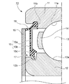
(1) 内周面に外輪軌道面を有する、固定輪である外輪と、外周面に内輪軌道面を有するとともに前記外周面の軸方向両端部に周溝が形成される、回転輪である内輪と、前記外輪軌道面と前記内輪軌道面との間に転動自在に設けられる複数の転動体と、円環板状の芯金及び前記芯金に被覆される弾性材を有して円環板状に形成され、前記外輪の軸方向両端部に取り付けられるシール部材と、を備えて、歯車変速機に使用される密封装置付き転がり軸受であって、前記シール部材の前記弾性材の内周縁部には、前記内輪の前記外周面に向かって延び且つ前記周溝に非接触の状態で挿入されるシールリップが設けられるとともに、前記シール部材の軸方向の外側に前記シール部材を覆う円環板状のスリンガが所定の間隙を存して対向配置されて、前記スリンガと前記周溝と前記シール部材と、の間にラビリンスシールが形成され、且つ前記スリンガは前記内輪に取り付けられて前記内輪と一体的に回転するとともに、前記スリンガの外周縁部は前記外輪の前記内周面に近接しており、前記外周縁部の軸方向の対向面に、前記シール部材に摺接し、前記内輪が高速に回転する際に所定の遠心力により径方向外方に開いて前記シール部材との摺接を解除する弾性リップが少なくとも一つ設けられることを特徴とする密封装置付き転がり軸受。
図1は本発明に係る密封装置付き転がり軸受の第1実施形態を説明するための拡大断面図、図2は弾性リップの動作を説明するための要部拡大断面図、図3は本発明に係る密封装置付き転がり軸受の第2実施形態を説明するための拡大断面図、図4は本発明に係る密封装置付き転がり軸受の第3実施形態を説明するための拡大断面図、図5は本発明に係る密封装置付き転がり軸受の変形例を説明するための拡大断面図である。
まず、図1及び図2を参照して、本発明の第1実施形態である密封装置付き転がり軸受10について説明する。
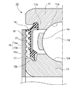
次に、図3を参照して、本発明の第2実施形態である密封装置付き転がり軸受20について説明する。なお、第1実施形態と重複する部分については、図に同一符号を付してその説明を省略あるいは簡略化する。
その他の構成及び作用効果は上記第1実施形態と同様である。
次に、図4を参照して、本発明の第3実施形態である密封装置付き転がり軸受30について説明する。なお、第1実施形態と重複する部分については、図に同一符号を付してその説明を省略あるいは簡略化する。
その他の構成及び作用効果は上記第1実施形態と同様である。
例えば、上記各実施形態では、スリンガ16を内輪12に取り付けた場合を例示したが、これに限定されず、スリンガ16を外輪11或いは外輪11及び内輪12の両方に取り付けてもよい。
また、スリンガ16は、図5に示すように、内輪12の外周面の軸方向両端部に形成される加締め溝12cに加締められることにより、内輪12に取り付けられてもよい。なお、外輪11にもスリンガ16を取り付ける場合は、外輪11の内周面の軸方向両端部に加締め溝を形成する。
また、スリンガ16は、回転軸に嵌合されることにより、内輪12に取り付けられてもよい。
また、シール部材15は非接触型のものであれば、その材質は特に限定されず、例えば、ゴム製、金属製、プラスチック製等を使用してもよい。
さらに、上記各実施形態では、スリンガ16の材質にステンレス鋼板、亜鉛メッキ鋼板等の金属板を使用したが、これに限定されず、その他の金属、プラスチック等を使用することができる。
11 外輪
11a 外輪軌道面
11b 係止溝
12,32 内輪
12a 内輪軌道面
12b 周溝
13 玉(転動体)
14 保持器
15 シール部材
15a 芯金
15b 弾性材
15c シールリップ
16 スリンガ
17 ラビリンスシール
18 弾性リップ
21 突起
Claims (1)
- 内周面に外輪軌道面を有する、固定輪である外輪と、外周面に内輪軌道面を有するとともに前記外周面の軸方向両端部に周溝が形成される、回転輪である内輪と、前記外輪軌道面と前記内輪軌道面との間に転動自在に設けられる複数の転動体と、円環板状の芯金及び前記芯金に被覆される弾性材を有して円環板状に形成され、前記外輪の軸方向両端部に取り付けられるシール部材と、を備えて、歯車変速機に使用される密封装置付き転がり軸受であって、
前記シール部材の前記弾性材の内周縁部には、前記内輪の前記外周面に向かって延び且つ前記周溝に非接触の状態で挿入されるシールリップが設けられるとともに、
前記シール部材の軸方向の外側に前記シール部材を覆う円環板状のスリンガが所定の間隙を存して対向配置されて、前記スリンガと前記周溝と前記シール部材と、の間にラビリンスシールが形成され、且つ
前記スリンガは前記内輪に取り付けられて前記内輪と一体的に回転するとともに、前記スリンガの外周縁部は前記外輪の前記内周面に近接しており、
前記外周縁部の軸方向の対向面に、前記シール部材に摺接し、前記内輪が高速に回転する際に所定の遠心力により径方向外方に開いて前記シール部材との摺接を解除する弾性リップが少なくとも一つ設けられることを特徴とする密封装置付き転がり軸受。
Priority Applications (1)
| Application Number | Priority Date | Filing Date | Title |
|---|---|---|---|
| JP2005088775A JP4654726B2 (ja) | 2005-03-25 | 2005-03-25 | 密封装置付き転がり軸受 |
Applications Claiming Priority (1)
| Application Number | Priority Date | Filing Date | Title |
|---|---|---|---|
| JP2005088775A JP4654726B2 (ja) | 2005-03-25 | 2005-03-25 | 密封装置付き転がり軸受 |
Publications (2)
| Publication Number | Publication Date |
|---|---|
| JP2006266451A JP2006266451A (ja) | 2006-10-05 |
| JP4654726B2 true JP4654726B2 (ja) | 2011-03-23 |
Family
ID=37202641
Family Applications (1)
| Application Number | Title | Priority Date | Filing Date |
|---|---|---|---|
| JP2005088775A Expired - Fee Related JP4654726B2 (ja) | 2005-03-25 | 2005-03-25 | 密封装置付き転がり軸受 |
Country Status (1)
| Country | Link |
|---|---|
| JP (1) | JP4654726B2 (ja) |
Families Citing this family (13)
| Publication number | Priority date | Publication date | Assignee | Title |
|---|---|---|---|---|
| JP2009144841A (ja) * | 2007-12-14 | 2009-07-02 | Jtekt Corp | オイルミスト潤滑型軸受装置 |
| JP4953022B2 (ja) * | 2008-03-07 | 2012-06-13 | 株式会社ジェイテクト | 軸受用密封装置 |
| JP4953023B2 (ja) * | 2008-03-07 | 2012-06-13 | 株式会社ジェイテクト | 軸受用密封装置 |
| EP2287483B1 (en) | 2008-05-27 | 2016-06-22 | JTEKT Corporation | Sealing device for rolling bearing |
| JP2009287596A (ja) * | 2008-05-27 | 2009-12-10 | Jtekt Corp | 転がり軸受用密封装置 |
| US8061901B2 (en) * | 2008-08-22 | 2011-11-22 | Baldor Electric Company | Extension member for a flinger of a bearing |
| DE102009033350A1 (de) * | 2009-07-16 | 2011-01-20 | Schaeffler Technologies Gmbh & Co. Kg | Dichtung mit kombinierter Dichtscheibe für eine Bandspannrolle |
| JP5790109B2 (ja) * | 2011-04-13 | 2015-10-07 | 株式会社ジェイテクト | 転がり軸受装置 |
| JP2015161366A (ja) | 2014-02-27 | 2015-09-07 | 日本精工株式会社 | シール付き転がり軸受 |
| EP2995829B1 (en) | 2014-09-12 | 2017-09-13 | Aktiebolaget SKF | Sealing device for a rolling bearing |
| FR3029994B1 (fr) * | 2014-12-15 | 2017-06-09 | Skf Ab | Palier a roulement comprenant un flasque d'etancheite |
| CN110966309A (zh) * | 2018-09-28 | 2020-04-07 | 皮尔轴承公司 | 轴承密封件及其应用 |
| JP7449136B2 (ja) * | 2020-03-24 | 2024-03-13 | Ntn株式会社 | シール付き転がり軸受 |
Citations (3)
| Publication number | Priority date | Publication date | Assignee | Title |
|---|---|---|---|---|
| JP2001304278A (ja) * | 1999-10-08 | 2001-10-31 | Nsk Ltd | 密封形軸受装置 |
| JP2002039196A (ja) * | 2000-06-30 | 2002-02-06 | Skf Industrie Spa | ころがり接触軸受 |
| JP2002339999A (ja) * | 2001-05-17 | 2002-11-27 | Koyo Seiko Co Ltd | 転がり軸受 |
-
2005
- 2005-03-25 JP JP2005088775A patent/JP4654726B2/ja not_active Expired - Fee Related
Patent Citations (3)
| Publication number | Priority date | Publication date | Assignee | Title |
|---|---|---|---|---|
| JP2001304278A (ja) * | 1999-10-08 | 2001-10-31 | Nsk Ltd | 密封形軸受装置 |
| JP2002039196A (ja) * | 2000-06-30 | 2002-02-06 | Skf Industrie Spa | ころがり接触軸受 |
| JP2002339999A (ja) * | 2001-05-17 | 2002-11-27 | Koyo Seiko Co Ltd | 転がり軸受 |
Also Published As
| Publication number | Publication date |
|---|---|
| JP2006266451A (ja) | 2006-10-05 |
Similar Documents
| Publication | Publication Date | Title |
|---|---|---|
| JP4654726B2 (ja) | 密封装置付き転がり軸受 | |
| JP2006336734A (ja) | 密封装置付き転がり軸受 | |
| JP6050080B2 (ja) | 密封型転がり軸受 | |
| JPH10252762A (ja) | 転がり軸受用密封装置 | |
| US20110222805A1 (en) | Seal equipped bearing assembly | |
| US6921083B2 (en) | Sealing apparatus and a rolling bearing and a clutch apparatus provided therewith | |
| JP2008151174A (ja) | 密封装置 | |
| JP2023027330A (ja) | 密封装置 | |
| EP1956258B1 (en) | Sealing apparatus and bearing apparatus having the same | |
| JP4115419B2 (ja) | シール装置 | |
| JP6532651B2 (ja) | シールリング付転がり軸受 | |
| JP6755156B2 (ja) | プーリユニット用シール付き転がり軸受 | |
| JP4719977B2 (ja) | 転がり軸受用密封装置とその搬送方法並びに組み付け方法 | |
| JP2008175301A (ja) | シール装置付き転がり軸受 | |
| JP2007198505A (ja) | 水ポンプ装置 | |
| JP2006258131A (ja) | 転がり軸受 | |
| JP6504060B2 (ja) | クリーナ用単列玉軸受 | |
| CN210118363U (zh) | 轮毂单元轴承 | |
| JP7367321B2 (ja) | 転がり軸受 | |
| JP2010043693A (ja) | 転がり軸受 | |
| JP6064783B2 (ja) | 転がり軸受 | |
| JP2008175312A (ja) | シール付き転がり軸受 | |
| JP4466139B2 (ja) | 転がり軸受の密封構造 | |
| JP2006022867A (ja) | 密封板付転がり軸受 | |
| JP2004183827A (ja) | 転がり軸受の密封装置 |
Legal Events
| Date | Code | Title | Description |
|---|---|---|---|
| RD04 | Notification of resignation of power of attorney |
Free format text: JAPANESE INTERMEDIATE CODE: A7424 Effective date: 20071128 |
|
| A621 | Written request for application examination |
Free format text: JAPANESE INTERMEDIATE CODE: A621 Effective date: 20080324 |
|
| A977 | Report on retrieval |
Free format text: JAPANESE INTERMEDIATE CODE: A971007 Effective date: 20100714 |
|
| A131 | Notification of reasons for refusal |
Free format text: JAPANESE INTERMEDIATE CODE: A131 Effective date: 20100727 |
|
| A521 | Written amendment |
Free format text: JAPANESE INTERMEDIATE CODE: A523 Effective date: 20100924 |
|
| TRDD | Decision of grant or rejection written | ||
| A01 | Written decision to grant a patent or to grant a registration (utility model) |
Free format text: JAPANESE INTERMEDIATE CODE: A01 Effective date: 20101124 |
|
| A01 | Written decision to grant a patent or to grant a registration (utility model) |
Free format text: JAPANESE INTERMEDIATE CODE: A01 |
|
| A61 | First payment of annual fees (during grant procedure) |
Free format text: JAPANESE INTERMEDIATE CODE: A61 Effective date: 20101207 |
|
| FPAY | Renewal fee payment (event date is renewal date of database) |
Free format text: PAYMENT UNTIL: 20140107 Year of fee payment: 3 |
|
| R150 | Certificate of patent or registration of utility model |
Ref document number: 4654726 Country of ref document: JP Free format text: JAPANESE INTERMEDIATE CODE: R150 Free format text: JAPANESE INTERMEDIATE CODE: R150 |
|
| LAPS | Cancellation because of no payment of annual fees |