JP4653621B2 - Radar device, radar signal processor, and radar device operating method - Google Patents
Radar device, radar signal processor, and radar device operating method Download PDFInfo
- Publication number
- JP4653621B2 JP4653621B2 JP2005285319A JP2005285319A JP4653621B2 JP 4653621 B2 JP4653621 B2 JP 4653621B2 JP 2005285319 A JP2005285319 A JP 2005285319A JP 2005285319 A JP2005285319 A JP 2005285319A JP 4653621 B2 JP4653621 B2 JP 4653621B2
- Authority
- JP
- Japan
- Prior art keywords
- difference
- gain
- signal
- phase difference
- initial
- Prior art date
- Legal status (The legal status is an assumption and is not a legal conclusion. Google has not performed a legal analysis and makes no representation as to the accuracy of the status listed.)
- Active
Links
Images


Description
本発明は、レーダ装置に関するものであり、特に、車両などに搭載されるレーダ装置およびその一部を構成するレーダ処理器ならびに当該レーダ装置の使用中の経時変化、温度変化を効果的に補償するためのレーダ装置動作方法に関するものである。 The present invention relates to a radar apparatus, and in particular, effectively compensates for a radar apparatus mounted on a vehicle and the like, a radar processor constituting a part thereof, and a change with time and a temperature change during use of the radar apparatus. It is related with the radar apparatus operating method for this.
近年、自動車等の車両に搭載され、走行車両との車間距離や走行車両の車速、方位などを測定する車載レーダ装置が注目されている。この種の車載レーダ装置は、測定された先行車との車間距離や車速、車両方位などに基づいて、衝突を予測して、例えばシートベルトをきつく締めるための「プリ・クラッシュ・セーフティー・システム」を実現したり、アクセルを操作せずとも前走車両との車間距離をほぼ一定に保持して走行するための「オート・クルーズ・コントロール・システム」を実現したりする目的で設置される。 In recent years, an on-vehicle radar device that is mounted on a vehicle such as an automobile and measures the inter-vehicle distance from the traveling vehicle, the vehicle speed, the direction, and the like of the traveling vehicle has attracted attention. This type of in-vehicle radar system is a “pre-crash safety system” that predicts a collision based on the measured distance from the preceding vehicle, vehicle speed, vehicle direction, etc., and tightens the seat belt, for example. It is installed for the purpose of realizing the "auto-cruise control system" that keeps the distance between the vehicle and the preceding vehicle almost constant without operating the accelerator.
車載用レーダ装置は、前走車両などの路上物体に対する方位および距離を測定することが一義的な目的である。これらの処理の中で、距離を測定(以下「測距」という)するための一方式として、例えばパルス状の電波を送信し、目標に反射して戻ってくる時間を測定する方式(パルスレーダー方式)や、例えばFM−CW電波を送信し、目標に反射して戻ってくる信号と現在の送信信号の周波数差とを測定し、周波数差を距離に換算する方式(FM−CWレーダ方式)などがある。また、方位を測定(以下「測角」という)するための一方式として、アンテナ、すなわちアンテナビームを機械的に左右に振る方式や、複数の固定アンテナおよび固定アンテナに連結される複数の受信系を有し、信号処理部にて位相回転演算を行うことにより電子的にアンテナビームを左右に振る方式(いわゆる電子走査方式)などがある。 The in-vehicle radar device has a primary purpose of measuring the azimuth and distance with respect to road objects such as a preceding vehicle. In these processes, as a method for measuring distance (hereinafter referred to as “ranging”), for example, a method of transmitting a pulsed radio wave and measuring the time of reflection and return to the target (pulse radar) System), for example, a system that transmits FM-CW radio waves, measures the frequency difference between the signal reflected back to the target and the current transmission signal, and converts the frequency difference into distance (FM-CW radar system) and so on. In addition, as a method for measuring the azimuth (hereinafter referred to as “angle measurement”), an antenna, that is, a method in which an antenna beam is mechanically moved to the left and right, a plurality of fixed antennas, and a plurality of receiving systems connected to the fixed antenna And a method of electronically oscillating the antenna beam left and right by performing phase rotation calculation in a signal processing unit (so-called electronic scanning method).
特に、電子的にアンテナビームを左右に走査する方式のレーダ装置の性能を精度良く実現するためには、レーダ装置に具備される複数のアンテナや受信系の位相特性や利得特性に関し、全受信系について、すべてほぼ同一の特性を具備させる必要がある。しかしながら、受信系を構成する部品は、アナログ回路部品が主流であるため、各部品間にバラツキが存在するのが一般的であり、全受信系の特性を常に完全に同一とすることは不可能である。したがって、例えば周囲温度が変化したり、時間が経過したりすると、複数の受信系の特性が個々独立的に変化して、レーダ装置の測角性能を低下させてしまうことにつながる。 In particular, in order to accurately realize the performance of a radar apparatus that electronically scans an antenna beam from side to side, the entire reception system is related to the phase characteristics and gain characteristics of a plurality of antennas and reception systems included in the radar apparatus. Need to have almost the same characteristics. However, since the components that make up the receiving system are mainly analog circuit components, there is generally variation between the components, and it is impossible to always make the characteristics of all receiving systems completely the same. It is. Therefore, for example, when the ambient temperature changes or the time elapses, the characteristics of the plurality of reception systems change independently, leading to deterioration in the angle measurement performance of the radar apparatus.
ここで、この種の問題点を解決しようとする従来技術文献の一つとして、例えば下記特許文献1が存在する。この文献では、つぎのような処理が行われる。まず、受信系の位相ずれと、利得ずれを検出するための基準アンテナ(当該文献中では「モニタアンテナ」と呼称)が具備され、この基準アンテナは、基準電波信号(当該文献中では「モニタRF信号」と呼称)をレーダ装置に向けて放射する。一方、レーダ装置は、放射された基準電波信号を自身の受信アンテナで受信し、アンテナに接続される各受信系の出力信号を信号処理部で比較処理することにより、アンテナを含めた各受信系の位相ずれおよび利得ずれを検出するようにしている。
Here, for example, the following
しかしながら、上記特許文献1に示される従来手法を、車載用レーダ装置に適用すると、以下のような問題点が生ずることになる。
(1)基準アンテナをレーダ装置の前面に所定の距離をもって設置する必要があるので、レーダ装置が大型化するとともに、車両特性や車両サイズなどに多大な影響を与える。
(2)また、レーダ装置前面の基準アンテナが存在する部分は、レーダ信号処理の死角となり、レーダ装置の機能性能を著しく低下させる。
(3)さらに、基準アンテナおよび基準アンテナに基準信号を供給するための信号配線が必要となり、装置が複雑になるとともにコストが増大する。
However, when the conventional method disclosed in
(1) Since it is necessary to install the reference antenna at a predetermined distance on the front surface of the radar apparatus, the radar apparatus is increased in size and greatly affects vehicle characteristics, vehicle size, and the like.
(2) Further, the portion where the reference antenna is present in front of the radar apparatus becomes a blind spot for radar signal processing, and the functional performance of the radar apparatus is significantly degraded.
(3) Further, the reference antenna and signal wiring for supplying the reference signal to the reference antenna are required, which complicates the apparatus and increases the cost.
本発明は、上記に鑑みてなされたものであって、車両特性や車両サイズへの影響ならびに装置自身の大型化、複雑化およびコスト増を防止または局限することができるレーダ装置およびレーダ信号処理器ならびにレーダ装置動作方法を提供することを目的とする。 The present invention has been made in view of the above, and a radar apparatus and a radar signal processor capable of preventing or limiting the influence on the vehicle characteristics and the vehicle size and the enlargement, complexity and cost of the apparatus itself. It is another object of the present invention to provide a radar apparatus operating method.
上述した課題を解決し、目的を達成するため、本発明にかかるレーダ装置は、送信アンテナから空間に放射された送信波の目標物からの反射波を複数の受信アンテナで受信し、該受信した複数の受信信号を用いてそれぞれ生成された複数の受信デジタル信号に基づいて前記目標物の方位情報を算出する測角信号処理部を具備する信号処理部を備えたレーダ装置において、前記信号処理部は、前記複数の受信デジタル信号に対して位相回転演算処理および利得調整演算処理を施した信号をそれぞれ生成して前記測角信号処理部に出力する位相/利得演算処理部と、前記複数の受信デジタル信号間に生ずる位相差/利得差を検出する位相差/利得差検出部と、レーダ運用前に前記位相差/利得差検出部によって予め検出された前記位相差/利得差を初期位相差/初期利得差として記憶する初期位相差/初期利得差記憶部と、前記初期位相差/初期利得差と、レーダ運用時に前記位相差/利得差検出部によって検出された位相差/利得差と、に基づいて前記位相/利得演算処理部に付与する位相差補正信号/利得差補正信号を生成出力する位相差/利得差補正量算出部と、を備え、前記位相/利得演算処理部は、前記位相差補正信号および前記利得差補正信号に基づいて前記測角信号処理部に出力する信号を補正することを特徴とする。 To solve the above problems and achieve an object, a radar device according to the present invention, the reflected wave from a target of signal wave transmission radiated into space from the transmission antenna is received at multiple receive antennas, the In the radar apparatus including a signal processing unit including an angle measurement signal processing unit that calculates azimuth information of the target based on a plurality of received digital signals respectively generated using a plurality of received signals received, the signal processing unit, and the phase / gain calculation processing unit for outputting the signal subjected to phase rotation processing and gain adjustment processing on the received digital signal of said multiple number of said angle measuring signal processing unit generates and respectively, wherein phase difference / the gain difference detector, the phase difference / gain difference which is previously detected by the phase difference / gain difference detector before radar operation for detecting a phase difference / gain difference generated between multiple received digital signal And initial phase difference / initial gain difference storage unit for storing as an initial phase difference / initial gain difference, the initial phase difference / initial gain difference and a phase difference / gain detected by the phase difference / gain difference detector during radar operation A phase difference / gain difference correction amount calculation unit that generates and outputs a phase difference correction signal / gain difference correction signal to be applied to the phase / gain calculation processing unit based on the difference, and the phase / gain calculation processing unit Corrects the signal output to the angle measurement signal processing unit based on the phase difference correction signal and the gain difference correction signal .
本発明にかかるレーダ装置によれば、受信デジタル信号間に生ずる受信系ごとの位相差/利得差を初期位相差/初期利得差として予め記憶し、実際のレーダ運用時に受信した受信信号に含まれる位相差/利得差を、この予め記憶された初期位相差/初期利得差に基づいて補正するようにしているので、この種の補正手段をレーダ装置に具備させる場合であっても、車両特性や車両サイズへの影響ならびに装置自身の大型化、複雑化およびコスト増を防止または局限することができるという効果を奏する。 According to the radar apparatus according to the present invention, previously stored phase difference / gain difference for each reception system generated between received digital signal as an initial phase difference / initial gain difference, in the received signal received at the time of actual radar operation The phase difference / gain difference to be corrected is corrected on the basis of the previously stored initial phase difference / initial gain difference. Therefore, even if this type of correction means is provided in the radar apparatus, the vehicle characteristics In addition, there is an effect that it is possible to prevent or limit the influence on the vehicle size and the enlargement, complication and cost increase of the apparatus itself.
以下に、本発明にかかるレーダ装置およびレーダ処理器ならびにレーダ装置動作方法の実施の形態を図面に基づいて詳細に説明する。なお、これらの実施の形態により本発明が限定されるものではない。 Embodiments of a radar apparatus, a radar processor, and a radar apparatus operating method according to the present invention will be described below in detail with reference to the drawings. Note that the present invention is not limited to these embodiments.
(従来技術適用の問題点)
まず、車載レーダ装置にかかる従来技術適用の問題点について説明する。例えば、図3は、従来手法の考え方に基づいて構成された車載用レーダ装置の構成例を示す図である。また、図4は、図3のように構成されたレーダ装置の探知覆域を模式的に示す図であり、モニタアンテナ102が、モニタアンテナ保持用冶具103を用いてレーダ装置101の前方に固定されている。従来手法の考え方では、出荷調整時および運用時の双方において、モニタアンテナを用いた受信系の試験調整(位相差、利得差の補正)を行う必要があり、図3に示すような構成を採用せざるを得ない。しかしながら、このような構成は、デザイン的な観点や、車両特性、車両サイズの観点からの問題点が大きく実現可能性は低い。また、図4に示すように、レーダ装置101の前方のモニタアンテナ102によって遮蔽される領域が検出不能領域となって、レーダ装置101の機能性能を著しく低下させることになる。
(Problems of applying conventional technology)
First, problems of application of the prior art to the on-vehicle radar device will be described. For example, FIG. 3 is a diagram illustrating a configuration example of an in-vehicle radar device configured based on the concept of the conventional method. 4 is a diagram schematically showing the detection coverage of the radar apparatus configured as shown in FIG. 3. The
つぎに、本発明にかかるレーダ装置の好適な実施の形態について具体的に説明するが、その説明の前に、本発明およびその実施態様における特徴について説明する。 Next, a preferred embodiment of a radar apparatus according to the present invention will be described in detail. Prior to the description, features of the present invention and its embodiments will be described.
(本発明およびその実施態様における特徴)
本発明は、レーダ装置の構成要素には含まれない基準信号発生装置やモニタアンテナ(基準アンテナ)などの測定ツールを用いて、レーダ装置が有する各受信系の位相差、利得差を測定し、これらを補正する第1の手段(手法)と、上記測定ツールを用いずに、レーダ装置自身で各受信系の位相差、利得差を測定し、これらを補正する第2の手段(手法)とを組み合わせて実施することに特徴がある。例えば、工場出荷時は、上記2つの手法を併用して試験調整を実施する。一方、レーダ装置が車両に取り付けられて出荷された後は、第2の手法による試験調整のみを実施する。つまり、出荷後は、自動車にはレーダ装置のみを搭載すればよく、従来技術のように、基準アンテナを車両に搭載する必要はない。また、それと同時に、従来技術での問題点が一挙に解消されることになる。なお、これら第1、第2の手段(手法)の詳細については後述する。
(Characteristics of the present invention and its embodiments)
The present invention uses a measurement tool such as a reference signal generation device and a monitor antenna (reference antenna) not included in the components of the radar device to measure the phase difference and gain difference of each receiving system of the radar device, First means (method) for correcting these, and second means (method) for measuring the phase difference and gain difference of each receiving system by the radar device itself without using the measurement tool, and correcting these. It is characterized by being implemented in combination. For example, at the time of factory shipment, the test adjustment is performed by using the above two methods together. On the other hand, after the radar apparatus is attached to the vehicle and shipped, only the test adjustment by the second method is performed. That is, after shipment, only the radar device needs to be mounted on the automobile, and there is no need to mount the reference antenna on the vehicle as in the prior art. At the same time, the problems in the prior art are solved at once. Details of these first and second means (methods) will be described later.
実施の形態1.
(装置の構成)
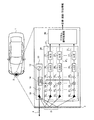
図1は、本発明の実施の形態1にかかるレーダ装置の搭載位置およびその構成を示すブロック図である。同図において、レーダ装置2は、車両1の前方部に設置されている。車載用のレーダ装置は、先行車両を検出する機能上あるいは搭載プラットフォームである車両の特性上、ヘッドライトやバンパーを避けた自車両前面の中央部付近に設置する必要があるが、同図に示した搭載部付近は、フロントグリルとラジエターとの間にある空間部分に該当し、その空間部分は車体のデザインの影響をほとんど受けることがないので、レーダ装置を設置する位置として好適である。また、同図の下部には、レーダ装置2の細部構成が示されている。同図に示すレーダ装置2は、送信部10、受信部20、デジタル信号処理部30を備えるように構成されている。
(Device configuration)
FIG. 1 is a block diagram showing a mounting position and configuration of a radar apparatus according to
ここで、図1に示すレーダ装置2の各構成部の詳細について説明する。同図において、送信部10は、レーダ装置として必要な所定の変調信号を出力する発振器12と、発振器12の出力信号を分配する分配器14と、分配器14の出力を増幅する高周波増幅器16と、高周波増幅器16に接続される送信アンテナ18と、を備えている。
Here, details of each component of the radar apparatus 2 shown in FIG. 1 will be described. In the figure, a
一方、受信部20は、複数の受信アンテナごとに構成された受信系21(211,212,・・・,21n)を備えている。これらの受信系21は、受信アンテナ22(221,222,・・・,22n)と、受信アンテナ22に接続され、受信アンテナ22からの受信信号を増幅する高周波増幅器23(231,232,・・・,23n)と、送信部10の分配器14を介して供給された信号(ローカル信号)に基づいて高周波増幅器23から出力された受信信号をダウンコンバートするミキサ24(241,242,・・・,24n)と、ミキサ24に接続されてダウンコンバート後の信号を増幅するビデオ増幅器25(251,252,・・・,25n)と、ビデオ増幅器25に接続されたフィルタ26(261,262,・・・,26n)と、フィルタ26の出力信号をアナログ/デジタル変換するA/Dコンバータ(以下「A/D」と表記)27(271,272,・・・,27n)と、を備えている。なお、高周波増幅器23としては、通常LNA(Low Noise Amp)と呼ばれる低雑音増幅器が用いられる。
On the other hand, the
デジタル信号処理部30は、例えばCPU、ROM、RAMなどを具備するマイクロプロセッサを備えている。デジタル信号処理部30の入力端には、受信部20からのアナログ/デジタル変換信号が入力され、デジタル信号処理部30の出力端からは、目標物に関する1以上の情報(例えば、目標物の相対距離情報、相対速度情報、方位情報など)が生成されて図示しないプリクラッシュセーフティーシステムやオートクルーズシステムなどに出力される。
The digital
なお、図1に示す装置の構成は一部の構成を略した簡略構成図であり、例えば、送信部10では、発振器12を変調する変調器、発振器12の出力を逓倍する逓倍器などの構成要素を省略している。
Note that the configuration of the apparatus shown in FIG. 1 is a simplified configuration diagram in which a part of the configuration is omitted. For example, the
また、図1に示すレーダ装置2では、デジタル信号処理部30への入力をデジタル入力とするためのA/D27を受信部20に備えるように構成しているが、このアナログ/デジタル変換機能をデジタル信号処理部30側に持たせるように構成してもよい。
In the radar apparatus 2 shown in FIG. 1, the A /
つぎに、デジタル信号処理部30の構成について説明する。図2は、図1に示したデジタル信号処理部30の細部構成を示すブロック図である。同図に示すデジタル信号処理部30は、A/D27の各出力をそれぞれの入力とする位相/利得演算処理部31および位相差/利得差検出部33、位相/利得演算処理部31の出力を入力とする測角信号処理部32、位相差/利得差検出部33の出力を出荷調整時と運用時とで切り換える切替スイッチ(SW)40、切替スイッチ40を介して位相差/利得差検出部33の出力が入力される位相差/利得差記憶部34、運用時に位相差/利得差検出部33の出力と位相差/利得差記憶部34の出力(所定第1出力)の符号反転出力とを加算する加算器(第1の加算器)35、加算器35の出力と位相差/利得差記憶部34の出力(所定第2出力)とを加算する加算器(第2の加算器)36および加算器36の出力に基づいて位相/利得演算処理部31に出力する位相差補正信号38、利得差補正信号39を算出して出力する位相差/利得差補正量算出部37の各構成部を備えている。
Next, the configuration of the digital
さらに、その細部構成として、位相/利得演算処理部31は、入力されたA/D変換出力の位相成分に対する位相回転量を演算する位相回転演算処理部41(411,412,・・・,41n)と、位相回転演算処理部41の出力の利得調整を行う利得調整演算処理部42(421,422,・・・,42n)と、を備え、位相差/利得差記憶部34は、出荷調整時に行われ、後述する基準アンテナ試験時の位相差/利得差を記憶保持する基準アンテナ信号初期位相差/初期利得差記憶部44と、同様に出荷調整時に行われ、後述する出荷時レドーム反射試験時の位相差/利得差を記憶保持するレドーム反射信号初期位相差/初期利得差記憶部45と、を備えている。
Furthermore, as its detailed configuration, the phase / gain
(装置の動作)
つぎに、図1および図2に示したレーダ装置の動作について説明する。なお、説明にあたり、まず、図1を参照して、実施の形態1にかかるレーダ装置2の全体動作について説明し、つぎに、図2,図5〜図8などを参照して、デジタル信号処理部30における細部動作について説明する。なお、図5は、出荷調整時における基準アンテナ試験の実施態様を説明するための図であり、図6は、出荷調整時における基準アンテナ試験時の処理手順を示すフローチャートであり、図7は、出荷調整時におけるレドーム反射試験(以下「出荷時レドーム反射試験」と呼称)の処理手順を示すフローチャートであり、図8は、運用時におけるレドーム反射試験(以下「運用時レドーム反射試験」と呼称)の処理手順を示すフローチャートである。
(Device operation)
Next, the operation of the radar apparatus shown in FIGS. 1 and 2 will be described. In the description, first, the overall operation of the radar apparatus 2 according to the first embodiment will be described with reference to FIG. 1, and then the digital signal processing will be described with reference to FIGS. The detailed operation in the
(装置の動作−全体動作)
図1において、図示しない変調器からの変調信号に基づいて発振器12にて生成された送信信号が、分配器14を介して高周波増幅器16で増幅され、送信アンテナ18から空間に対して放射される。一方、目標などからの反射信号が受信アンテナ22で受信される。この受信信号は、高周波増幅器23で増幅され、ミキサ24に出力される。ミキサ24では、高周波増幅器23から出力された受信信号が、分配器14を介して分配された送信信号に基づいてダウンコンバートされる。ミキサ24から出力されたダウンコンバート信号は、フィルタ26にて所望帯域の信号に変換された後、さらにA/D27にてデジタル信号に変換されてデジタル信号処理部30に出力される。デジタル信号処理部30は、受信部20の出力に基づいて目標物に関する相対距離、相対速度および方位などの出力情報のうちの少なくとも1以上の情報を出力する。
(Operation of the device-overall operation)
In FIG. 1, a transmission signal generated by an
(装置の動作−詳細動作−基準アンテナ試験時の動作)
つぎに基準アンテナ試験時の動作について説明する。なお、基準アンテナ試験では、前述したように、レーダ装置の構成要素には含まれない測定ツールが必要であり、当該測定ツールを用いた測定構成を示す図が図5である。まず、同図に示すように、車両1に搭載されたレーダ装置2の正面で、かつ十分に距離が離れた場所に、基準信号発生装置6に接続された基準アンテナ7を設置する。つぎに、レーダ装置2の送信は停止し(具体的には、例えば図1における高周波増幅器16の動作を停止する)、基準アンテナ7から基準信号8をレーダ装置2に向けて発射する。レーダ装置2の受信部20は、基準アンテナ7からの信号を受信し、デジタル信号処理部30へ出力する。なお、基準アンテナ7とレーダ装置2とは十分に離間されているので、受信アンテナ22で受信される基準信号の位相と振幅とは各受信系間では等しいとみなすことができる。したがって、試験手法に起因して発生する各受信系ごとの位相のバラツキ(位相差)および利得のバラツキ(利得差)は殆ど無視することができる。
(Operation of device-Detailed operation-Operation during reference antenna test)
Next, the operation during the reference antenna test will be described. In the reference antenna test, as described above, a measurement tool that is not included in the constituent elements of the radar apparatus is required, and FIG. 5 shows a measurement configuration using the measurement tool. First, as shown in the figure, a
一方、従来技術の項で説明したように、各受信系を構成するアンテナや電子部品の特性バラツキにより、各受信系ごとの特性を常に完全に同一とすることは不可能である(たとえ、製造直後であっても固有の位相差、利得差(以下、それぞれ「初期位相差」、「初期利得差」という)が存在する)。したがって、レーダ装置の受信性能を向上させるためには、各受信系ごとに必然的に生じる初期位相差・初期利得差を記憶しておくことが好ましい。なお、図6は、これらの初期位相差・初期利得差を記憶するためのフローであり、いま、このフローの各処理について図2および図6を参照して説明する。また、基準アンテナ試験時における各受信系ごとの位相差/利得差を、後述の出荷時レドーム反射試験および運用時レドーム反射試験の際にそれぞれ取得される位相差/利得差と区別するため、それぞれ「基準アンテナ信号初期位相差」、「基準アンテナ信号初期利得差」と呼称する。 On the other hand, as explained in the section of the prior art, it is impossible to always make the characteristics of each receiving system completely the same due to variations in the characteristics of the antennas and electronic components constituting each receiving system (for example, manufacturing) Even immediately after, there are inherent phase differences and gain differences (hereinafter referred to as “initial phase differences” and “initial gain differences”, respectively). Therefore, in order to improve the reception performance of the radar apparatus, it is preferable to store the initial phase difference and the initial gain difference that inevitably occur for each reception system. FIG. 6 is a flow for storing these initial phase differences and initial gain differences. Now, each processing in this flow will be described with reference to FIGS. 2 and 6. In addition, in order to distinguish the phase difference / gain difference for each receiving system at the time of the reference antenna test from the phase difference / gain difference acquired at the time of the shipping radome reflection test and the operating radome reflection test described later, respectively, These are referred to as “reference antenna signal initial phase difference” and “reference antenna signal initial gain difference”.
図2において、切替スイッチ40は出荷調整時側に設定される(図6:ステップS101)。このとき、位相差/利得差検出部33と位相差/利得差記憶部34とが接続され、各受信系ごとの受信信号がデジタル信号処理部30に入力されるとともに、位相差/利得差検出部33にて検出された初期位相差および初期利得差が位相差/利得差記憶部34の基準アンテナ信号初期位相差/初期利得差記憶部44に記憶される(図6:ステップS102)。
In FIG. 2, the
(装置の動作−詳細動作−出荷時レドーム反射試験時の動作)
つぎに出荷時レドーム反射試験時の動作について説明する。なお、出荷時レドーム反射試験では、基準アンテナ試験時とは異なり、当該試験で用いた測定ツールは不要であり、自身のレドームで反射した反射信号が利用される。また、出荷時レドーム反射試験の概念を図1に示している。図1には、送信アンテナ18から前方方向に放射される主送信波4と、送信アンテナ18から斜め方向に放射され、レドーム3で反射されたレドーム反射波5が受信系21の受信アンテナ22でそれぞれ受信される様子が示されている。なお、レドームとは、送受信波を効率よく通過させる一方で、装置を構成するアンテナ、電子部品等を外界の水分や埃等から保護するための保護部材である。
(Operation of device-Detailed operation-Operation during radome reflection test at shipment)
Next, the operation at the time of shipment radome reflection test will be described. In the radome reflection test at the time of shipment, unlike the reference antenna test, the measurement tool used in the test is unnecessary, and the reflected signal reflected by its own radome is used. The concept of the radome reflection test at the time of shipment is shown in FIG. In FIG. 1, the
ところで、レーダ装置が電波を送信すると、図1の主送信波4のように送信波の大部分は前方に放射される。レドームは、本来的には、電波を効率よく通過させるものであるが、実際には一部の電波は通過せずに反射してしまう。特に、車載用レーダ装置で多用されるミリ波帯電波の場合には、この反射量が大きいという特性を有している。なお、出荷時レドーム反射試験は、このようなレドームでの反射を積極的に利用するものである。また、図7は、出荷時レドーム反射試験時における位相差/利得差を記憶するためのフローであり、いま、このフローの各処理について図2および図7を参照して説明する。なお、出荷時レドーム反射試験時における各受信系ごとの位相差/利得差を、前述の基準アンテナ試験および後述の運用時レドーム反射試験の際にそれぞれ取得される位相差/利得差と区別するため、それぞれ「レドーム反射信号初期位相差」、「レドーム反射信号初期利得差」と呼称する。
By the way, when the radar apparatus transmits radio waves, most of the transmission waves are radiated forward like the
図2において、基準アンテナ試験時と同様に、切替スイッチ40は出荷調整時側に設定される(図7:ステップS201)。一方、基準アンテナ試験時とは異なり、送信機能を有効にする。このとき、位相差/利得差検出部33と位相差/利得差記憶部34とが接続され、各受信系ごとの受信信号(レドーム反射信号)がデジタル信号処理部30に入力されるとともに、位相差/利得差検出部33にて検出されたレドーム反射信号初期位相差およびレドーム反射信号初期利得差が位相差/利得差記憶部34のレドーム反射信号初期位相差/初期利得差記憶部45に記憶される(図7:ステップS202)。なお、出荷時レドーム反射試験は、レドーム反射波を受信しているので、各受信系ごとに(送信アンテナ→レドーム→受信アンテナ)の信号伝達距離が異なるので、各受信系ごとに生ずる位相差/利得差は、基準アンテナ試験時と比べて大きくなる。
In FIG. 2, the
(装置の動作−詳細動作−運用時レドーム反射試験時の動作)
つぎに運用時レドーム反射試験時の動作について説明する。この、運用時レドーム反射試験は、出荷時等に行われる上述の基準アンテナ試験および出荷時レドーム反射試験とは異なり、レーダ装置の運用中に実行される試験である。なお、この試験は、ユーザ側で特に意識することなく自動的に実行される。また、この試験では、出荷時レドーム反射試験時と同様に、自身のレドームで反射した反射信号が利用される。
(Operation of device-Detailed operation-Operation during operation radome reflection test)
Next, the operation during the operation radome reflection test will be described. This radome reflection test during operation is a test that is performed during operation of the radar apparatus, unlike the above-described reference antenna test and radome reflection test performed during shipment. This test is automatically executed without any particular awareness on the user side. Further, in this test, the reflected signal reflected by its own radome is used as in the radome reflection test at the time of shipment.
なお、図8は、運用時レドーム反射試験時における位相差/利得差を記憶するためのフローであり、いま、このフローの各処理について図2および図8を参照して説明する。 FIG. 8 is a flow for storing the phase difference / gain difference during the operation radome reflection test. Now, each processing of this flow will be described with reference to FIGS.
図2において、切替スイッチ40は、基準アンテナ試験および出荷時レドーム反射試験の終了後、運用時側に設定される(図8:ステップS301)。なお、これ以後、例えば故障修理を実施する場合などを除き、切替スイッチ40は常時「運用時」に固定される。また、レドーム反射信号が位相差/利得差検出部33に入力され各受信系ごとの位相差/利得差が検出される(図8:ステップS302)。つぎに、ステップS302で検出された位相差/利得差とレドーム反射信号初期位相差/初期利得差記憶部45に記憶されている記憶値との各差分値が各受信系ごとに算出されて加算器36に出力される(図8:ステップS303)。さらに、基準アンテナ信号初期位相差/初期利得差記憶部44に記憶されている記憶値とステップS303で算出された位相差/利得差(加算器35の出力)との各加算値が各受信系ごとに算出されて加算器36に出力されて位相差/利得差補正量算出部37に出力される(図8:ステップS304)。位相差/利得差補正量算出部37では、各受信系ごとの位相差/利得差補正量が算出され、それぞれ位相差補正信号38および利得差補正信号39として位相/利得演算処理部31に出力される(図8:ステップS305)。位相/利得演算処理部31の位相回転演算処理部41では、位相差補正信号38に基づいて入力信号に対する位相回転演算処理(受信信号の位相補正)が各受信系ごとに行われ、引き続き、位相/利得演算処理部31の利得調整演算処理部42では、利得差補正信号39に基づいて位相回転演算処理部41の出力信号に対する利得調整演算処理(受信信号の利得補正)が各受信系ごとに行われ、その出力が測角信号処理部32に出力される(図8:ステップS306)。なお、測角信号処理部32では、位相/利得演算処理部31の出力に基づいて所定の測角信号処理(デジタルビームフォーミング等の処理)が行われ、精度の向上した信号到来方位が得られる(図8:ステップS307)。
In FIG. 2, the
なお、上記のステップS306では、まず、位相回転演算処理部41にて位相回転演算処理を行い、引き続き、利得調整演算処理部42にて利得調整演算処理を実施するようにしているが、これらの処理の順番を逆にしても構わない。すなわち、まず、利得調整演算処理部42にて利得調整演算処理を行い、引き続き、位相回転演算処理部41にて位相回転演算処理を実施するようにしてもよい。
In step S306, first, the phase rotation
また、上記のステップS303,S304では、まず、位相差/利得差検出部33で検出された検出値とレドーム反射信号初期位相差/初期利得差記憶部45に記憶されている記憶値との各差分値を基準アンテナ信号初期位相差/初期利得差記憶部44に記憶されている記憶値に加算するようにしているが、レドーム反射信号初期位相差/初期利得差記憶部45に記憶されている記憶値と位相差/利得差検出部33で検出された検出値との各差分値を基準アンテナ信号初期位相差/初期利得差記憶部44に記憶されている記憶値から減算処理するようにしてもよい。また、上記のステップS303,S304の演算順序を逆にしても構わない。すなわち、基準アンテナ信号初期位相差/初期利得差記憶部44に記憶されている記憶値からレドーム反射信号初期位相差/初期利得差記憶部45に記憶されている記憶値を減算した値と、位相差/利得差検出部33で検出された検出値とを加算するようにしてもよい。
In the above steps S303 and S304, each of the detected value detected by the phase difference / gain
(デジタル信号処理部の動作の考察)
ここで、デジタル信号処理部の動作について若干の考察を加える。いま、各受信系特性の温度変動も経時変動もないものと仮定する。このとき、位相差/利得差検出部33の出力と、レドーム反射信号初期位相差/初期利得差記憶部45の記憶値との差分値はゼロとなる。したがって、このゼロ値が基準アンテナ信号初期位相差/初期利得差記憶部44の出力に加算されることになるので、位相差/利得差補正量算出部37に入力される信号は、基準アンテナ信号初期位相差/初期利得差記憶部44の記憶内容そのものとなる。つまり、温度変動や経時変動がない状態では、レーダ装置は、「初期位相差/初期利得差」のみを補正することになる。
(Consideration of operation of digital signal processor)
Here, some consideration is given to the operation of the digital signal processing unit. Now, it is assumed that there is no temperature variation or time-dependent variation of each receiving system characteristic. At this time, the difference value between the output of the phase difference / gain
一方、もし、各受信系の特性の温度変動や、経時変動が発生したとすれば、位相差/利得差検出部33の出力と、レドーム反射信号初期位相差/初期利得差記憶部45の記憶値との差はゼロとはならない。この差が温度変動、経時変動に起因する各受信系ごとの位相変動成分および利得変動成分となる。これらの差分値と基準アンテナ信号初期位相差/初期利得差記憶部44の記憶値とを加算することにより、位相差/利得差補正量算出部37に入力される信号は、「初期位相差/初期利得差」と「温度変動、経時変動による位相差/利得差」とを加味したものとなる。つまり、このレーダ装置は、「初期位相差/初期利得差」と「温度変動、経時変動による位相差/利得差」の双方を補正することとなる。
On the other hand, if temperature fluctuations or temporal fluctuations of the characteristics of each receiving system occur, the output of the phase difference / gain
レーダ装置が搭載される車両(自動車)は、高温多湿地や、寒冷地等の様々な環境で使用され、あるいは昼間時には直射日光が直接的に照射されることもあり、環境条件は、場所、時間、季節等によって大きく変動する。したがって、出荷時調整を精度よく行ったとしても、各受信系の特性変動は不可避である。一方、この実施の形態のレーダ装置では、上記のように、「初期位相差/初期利得差」に加えて、「温度変動、経時変動による位相差/利得差」を補正するようにしているので、測角信号処理の精度を著しく向上させることができる。なお、上記でも触れたように、「運用時レドーム反射試験」と称するこの処理は、実際のレーダ処理の合間に、例えば10分に1回とか、20分に1回とかの任意の処理間隔で実施することができる。また、この処理間隔を可変設定とすることも容易であり、使用する環境条件に応じて好適な処理間隔を設定することにより、レーダ信号処理の処理精度と処理速度との間のバランスをとることができる。 Vehicles (automobiles) equipped with radar devices are used in various environments such as hot and humid regions and cold regions, or may be directly exposed to direct sunlight during the daytime. Fluctuates greatly depending on time and season. Therefore, even if the adjustment at the time of shipment is performed with accuracy, the characteristic variation of each receiving system is unavoidable. On the other hand, in the radar apparatus of this embodiment, as described above, in addition to the “initial phase difference / initial gain difference”, the “phase difference / gain difference due to temperature variation and temporal variation” is corrected. The accuracy of angle measurement signal processing can be significantly improved. As mentioned above, this process called “operation radome reflection test” is performed at an arbitrary processing interval of, for example, once every 10 minutes or once every 20 minutes between actual radar processes. Can be implemented. In addition, it is easy to set the processing interval to be variable, and by setting a suitable processing interval according to the environmental conditions to be used, it is possible to balance the processing accuracy and processing speed of radar signal processing. Can do.
(レドーム反射信号と目標信号との識別)
図9は、レドーム反射信号と先行車両からの反射信号の差異を説明するための模式的概念図である。上記の運用時レドーム反射試験では、各受信系は、レドーム反射信号以外に、先行車等の路上物体からの反射信号も同時に受信する。したがって、各受信系の位相変動、利得変動を補正する場合は、各受信系が受信した信号から、レドーム反射信号を区別しなければならない。例えば、FM−CWレーダであれば、その測距原理により、近距離の物体からの反射波は、受信出力信号の周波数が低く、遠距離の物体からの反射波は受信出力信号の周波数が高い(図9参照)。一方、レドームと各受信アンテナとの間の距離は、先行車等と比較すると極めて短い。また、ミリ波帯の周波数領域ではレドーム反射量は大きく、レドーム反射信号の受信レベルは先行車等よりも大きいか、等しい程度である(図9参照)。したがって、デジタル信号処理部では、受信出力信号の最も低い周波数成分をレドーム反射信号と認識し、この信号に対して上述の位相差/利得補正処理を実施すればよい。なお、例えば、ミリ波帯の周波数領域のように、レドーム反射信号の受信レベルが先行車等からの反射信号レベルよりも大きい場合には、受信レベルに閾値を設け、当該閾値に基づいてレドーム反射信号であるか否かを判定するようにしてもよい。
(Distinguish between radome reflection signal and target signal)
FIG. 9 is a schematic conceptual diagram for explaining a difference between a radome reflection signal and a reflection signal from a preceding vehicle. In the above operation radome reflection test, each receiving system simultaneously receives a reflection signal from a road object such as a preceding vehicle in addition to the radome reflection signal. Therefore, when correcting the phase fluctuation and gain fluctuation of each receiving system, the radome reflected signal must be distinguished from the signal received by each receiving system. For example, in the case of FM-CW radar, the frequency of a reflected wave from a short-distance object has a low frequency of the received output signal and the wave of a reflected wave from a long-distance object has a high frequency of the received output signal due to the principle of ranging. (See FIG. 9). On the other hand, the distance between the radome and each receiving antenna is extremely short compared to a preceding vehicle or the like. Further, the radome reflection amount is large in the millimeter waveband frequency region, and the reception level of the radome reflection signal is greater than or equal to that of the preceding vehicle or the like (see FIG. 9). Therefore, the digital signal processing unit may recognize the lowest frequency component of the received output signal as a radome reflection signal and perform the above-described phase difference / gain correction processing on this signal. For example, when the reception level of the radome reflection signal is higher than the reflection signal level from the preceding vehicle or the like, such as in the frequency region of the millimeter wave band, a threshold is provided for the reception level, and the radome reflection is based on the threshold. You may make it determine whether it is a signal.
以上説明したように、この実施の形態のレーダ装置によれば、受信系を構成する構成品の特性バラツキに起因して受信デジタル信号間に生ずる受信系ごとの位相差/利得差を初期位相差/初期利得差として予め記憶し、実際のレーダ運用時に受信した受信信号に含まれる位相差/利得差を、この予め記憶された初期位相差/初期利得差に基づいて補正するようにしているので、この種の補正手段をレーダ装置に具備させる場合であっても、車両特性や車両サイズへの影響ならびに装置自身の大型化、複雑化およびコスト増を防止または局限することができる。 As described above, according to the radar apparatus of this embodiment, the phase difference / gain difference between the reception digital signals generated between the reception digital signals due to the characteristic variation of the components constituting the reception system is determined as the initial phase difference. / Initial gain difference is stored in advance, and the phase difference / gain difference included in the received signal received during actual radar operation is corrected based on the previously stored initial phase difference / initial gain difference. Even when this type of correction means is provided in the radar apparatus, it is possible to prevent or limit the influence on the vehicle characteristics and the vehicle size, as well as the enlargement, complication, and cost increase of the apparatus itself.
また、この実施の形態のレーダ装置によれば、受信アンテナ前方の所定の距離位置に配置された基準アンテナからの直接波を受信した受信出力に基づいて検出した初期位相差/初期利得差を、基準アンテナ信号初期位相差/初期利得差として記憶するようにしているので、レーダ装置の初期状態における、位相差/利得差(初期位相差/初期利得差)の影響を効果的に低減することができる。 Further, according to the radar apparatus of this embodiment, the initial phase difference / initial gain difference detected based on the reception output received from the direct wave from the reference antenna disposed at a predetermined distance position in front of the reception antenna, Since the reference antenna signal initial phase difference / initial gain difference is stored, the influence of the phase difference / gain difference (initial phase difference / initial gain difference) in the initial state of the radar apparatus can be effectively reduced. it can.
また、この実施の形態のレーダ装置によれば、自身の送信波による自身のレドームからの反射波を利用して受信した受信出力に基づいて検出した初期位相差/初期利得差を、レドーム反射信号初期位相差/初期利得差として記憶するようにしているので、後発的な、温度変動や、経時変動による位相差/利得差の影響を効果的に低減することができる。 Further, according to the radar apparatus of this embodiment, the initial phase difference / initial gain difference detected based on the received output received from the own radome using the reflected wave from the own radome is converted into the radome reflected signal. Since it is stored as the initial phase difference / initial gain difference, it is possible to effectively reduce the influence of the phase difference / gain difference due to subsequent temperature fluctuations and temporal fluctuations.
なお、この実施の形態では、電子的にアンテナビームを左右に走査する方式のレーダ装置への適用例をその一例として説明してきたが、機械的に走査する方式のレーダ装置であっても、例えばモノパルス方式のレーダ装置であれば、少なくとも2チャンネルの受信系を有しているので、当該2チャンネルの受信系の受信特性のバラツキの影響を局限する上で、本手法は有効に作用する。 In this embodiment, an example of application to a radar apparatus that electronically scans an antenna beam to the left and right has been described as an example. However, even a radar apparatus that mechanically scans, for example, Since the monopulse radar device has at least a two-channel reception system, the present technique works effectively in limiting the influence of variations in reception characteristics of the two-channel reception system.
なお、この実施の形態では、基準アンテナ信号初期位相差/初期利得差やレドーム反射信号初期位相差/初期利得差を初期位相差/初期利得差記憶部に記憶する処理を出荷調整時として説明したが、出荷調整時に限定する趣旨ではない。例えば、レーダ装置のみを新規な製品と交換した場合や、例えば衝突事故によってバンパーやフロントグリルなどが変形した場合に、ディーラー等でレーダ装置の再調整を行うような場合にも、切替スイッチを出荷調整時側に設定して、新たな記憶値を記憶させるようにすればよい。すなわち、初期位相差/初期利得差記憶部への記憶処理は、レーダ装置の運用時以外の任意のときに実施することができる。 In this embodiment, the process of storing the reference antenna signal initial phase difference / initial gain difference and the radome reflection signal initial phase difference / initial gain difference in the initial phase difference / initial gain difference storage unit has been described as the time of shipping adjustment. However, this is not intended to be limited at the time of shipping adjustment. For example, when the radar device is replaced with a new product, or when the bumper or front grille is deformed due to a collision, for example, when the radar device is readjusted by a dealer or the like, the switch is shipped. A new stored value may be stored by setting the adjustment side. That is, the storage process in the initial phase difference / initial gain difference storage unit can be performed at any time other than during the operation of the radar apparatus.
実施の形態2.
(装置の構成)
図10は、本発明の実施の形態2にかかるレーダ装置の構成を示すブロック図である。同図に示すレーダ装置2aは、必要数の受信アンテナ22(221,222,・・・,22n)を個々に接続する受信アンテナ切替手段51を具備し、単一の受信系を共通的に使用するために複数の受信アンテナを切り替えて使用するような構成とされている。また、図11は、図10に示したデジタル信号処理部30の細部構成を示す図である。同図に示すデジタル信号処理部30aは、受信部20の出力であるA/D27の出力を各受信系に対応する処理部に振り分ける出力振り分け手段52を具備している。なお、その他の構成については、図1および図2に示した実施の形態1の構成と同一または同等であり、それらの構成部には同一符号を付して示し、その説明を省略する。
Embodiment 2. FIG.
(Device configuration)
FIG. 10 is a block diagram showing a configuration of the radar apparatus according to Embodiment 2 of the present invention. The
(装置の特徴)
図10に示すレーダ装置は、複数の受信アンテナ22を切り替えて使用するように構成されているので、高周波増幅器、ミキサ、ビデオ増幅器、フィルタおよびA/Dコンバータを共用することができ、受信部の製造コストを大幅に低減することができる。なお、アンテナ、切替えスイッチの電気特性は温度や経時的要素によりその特性が変動して各受信系の位相差/利得差にバラツキを生じさせる。したがって、この実施の形態のような単一の受信系のみを有するレーダ装置であっても、各受信系の位相差/利得差を補正することは、レーダ装置の測角性能、すなわち目標方位情報の精度を向上させるという観点において重要な処理となる。
(Features of the device)
Since the radar apparatus shown in FIG. 10 is configured to use a plurality of
(装置の動作)
図10に示した受信アンテナ切替手段51と、図11に示した出力振り分け手段52とは、時間的に連動して切替制御される。例えば、図10に示すように、受信アンテナ221が選択されている場合には、図11においても受信アンテナ221に対応する位相回転演算処理部411が選択され、以下、出力振り分け手段52の切替タイミングに連動して他の位相回転演算処理部412〜41nが選択される。なお、位相差/利得差補正量算出部37から出力される位相差補正信号38および利得差補正信号39は、出力振り分け手段52の切替タイミングに同期して出力されるように制御してもよいし、あるいは出力振り分け手段52の切替タイミングとは連動せず非同期で出力されるように制御してもよい。この場合、すなわち、位相差補正信号38および利得差補正信号39を非同期で出力する場合には、デジタル信号処理部で構成される複数の受信系のうち、どの受信系に対する補正量なのかを弁別して出力するようにすればよい。
(Device operation)
The receiving antenna switching means 51 shown in FIG. 10 and the output distribution means 52 shown in FIG. For example, as shown in FIG. 10, when the receiving
以上説明したように、この実施の形態のレーダ装置によれば、「初期位相差/初期利得差」と「温度変動、経時変動による位相差/利得差」の双方を補正するための構成を、高周波増幅器、ミキサ、ビデオ増幅器、フィルタおよびA/Dコンバータ等が共用されるレーダ装置に適用することができるので、本実施の形態を適用するレーダ装置の製造コストを大幅に低減することができる。 As described above, according to the radar apparatus of this embodiment, the configuration for correcting both the “initial phase difference / initial gain difference” and the “phase difference / gain difference due to temperature variation and temporal variation” Since it can be applied to a radar apparatus in which a high-frequency amplifier, a mixer, a video amplifier, a filter, an A / D converter, and the like are shared, the manufacturing cost of the radar apparatus to which this embodiment is applied can be greatly reduced.
実施の形態3.
(装置の構成)
図12は、本発明の実施の形態3にかかるレーダ装置のデジタル信号処理部の構成を示すブロック図である。同図に示すデジタル信号処理部30は、図2に示したデジタル信号処理部30の構成から基準アンテナ信号初期位相差/初期利得差記憶部44を取り除いた、レドーム反射信号初期位相差/初期利得差記憶部45のみを有する位相差/利得差記憶部34aを有している。なお、その他の構成については、図2に示した実施の形態1の構成と同一または同等であり、それらの構成部には同一符号を付して示し、その説明を省略する。
Embodiment 3 FIG.
(Device configuration)
FIG. 12 is a block diagram showing the configuration of the digital signal processing unit of the radar apparatus according to Embodiment 3 of the present invention. The digital
(装置の特徴)
図12に示す構成のレーダ装置では、各受信系を構成するアンテナや電子部品の特性バラツキが小さい場合(特性バラツキの小さい電子部品を用いて構成されている場合)を念頭に置いているので、「初期位相差/初期利得差」は殆ど発生せず、「温度変動、経時変動による位相差/利得差」のみを考慮すればよい。したがって、この実施の形態のレーダ装置では、実施の形態1で説明した出荷時の基準アンテナ試験が省略され、出荷時レドーム反射試験のみが実施される。その結果、位相差/利得差検出部33にて検出されたレドーム反射信号初期位相差およびレドーム反射信号初期利得差のみが位相差/利得差記憶部34のレドーム反射信号初期位相差/初期利得差記憶部45に記憶される。なお、このように構成されたレーダ装置であっても、レドーム反射信号初期位相差およびレドーム反射信号初期利得差に基づいて、変動要素の大きな「温度変動、経時変動による位相差/利得差」を補正することができるので、レーダ装置の測角性能向上に充分に寄与することができる。
(Features of the device)
In the radar apparatus having the configuration shown in FIG. 12, since the characteristic variation of the antennas and electronic components that constitute each receiving system is small (when configured using electronic components with small characteristic variations), “Initial phase difference / initial gain difference” hardly occurs, and only “phase difference / gain difference due to temperature variation and temporal variation” should be considered. Therefore, in the radar apparatus according to this embodiment, the reference antenna test at the time of shipment described in the first embodiment is omitted, and only the radome reflection test at the time of shipment is performed. As a result, only the radome reflection signal initial phase difference and the radome reflection signal initial gain difference detected by the phase difference / gain
なお、この実施の形態では、レドーム反射信号初期位相差/初期利得差記憶部45のみを有する構成を図2に示した実施の形態1に適用した例について説明したが、図11に示す実施の形態2に適用することも可能である。特に、図11に示す構成では、アンテナを除く、高周波増幅器、ミキサ、ビデオ増幅器、フィルタおよびA/Dコンバータ等を共用することができるので、各受信系の特性バラツキを低減させることが容易であり、本実施の形態の構成による効果を十二分に発揮することができる。
In this embodiment, the example in which the configuration having only the radome reflection signal initial phase difference / initial gain
以上のように、本発明および本発明にかかる手法は、移動物体の距離、速度、方位を検出するレーダ装置、あるいはその構成品に有用であり、特に、レーダ装置における一定の性能を確保する場合のコスト低減に効果的である。 As described above, the present invention and the method according to the present invention are useful for a radar device that detects the distance, speed, and direction of a moving object, or a component thereof, and particularly in a case where certain performance is ensured in the radar device. It is effective in reducing the cost of
1 車両
2,2a,101 レーダ装置
3 レドーム
4 主送信波
5 レドーム反射波
6 基準信号発生装置
7 基準アンテナ
8 基準信号
10 送信部
12 発振器
14 分配器
16 高周波増幅器
18 送信アンテナ
20 受信部
21 受信系
22 受信アンテナ
23 高周波増幅器
24 ミキサ
25 ビデオ増幅器
26 フィルタ
27 A/Dコンバータ
30,30a デジタル信号処理部
31 位相/利得演算処理部
32 測角信号処理部
33 位相差/利得差検出部
34,34a 位相差/利得差記憶部
35,36 加算器
37 位相差/利得差補正量算出部
38 位相差補正信号
39 利得差補正信号
40 切替スイッチ
41 位相回転演算処理部
42 利得調整演算処理部
44 基準アンテナ信号初期位相差/初期利得差記憶部
45 レドーム反射信号初期位相差/初期利得差記憶部
102 モニタアンテナ
103 モニタアンテナ保持用冶具
DESCRIPTION OF
Claims (11)
前記信号処理部は、
前記複数の受信デジタル信号に対して位相回転演算処理および利得調整演算処理を施した信号をそれぞれ生成して前記測角信号処理部に出力する位相/利得演算処理部と、
前記複数の受信デジタル信号間に生ずる位相差/利得差を検出する位相差/利得差検出部と、
レーダ運用前に、自身の送信波による自身のレドームからの反射波を利用して受信した受信出力に基づき、前記位相差/利得差検出部によって予め検出された前記位相差/利得差をレドーム反射信号初期位相差/初期利得差として記憶する初期位相差/初期利得差記憶部と、
レーダ運用時に、目標物からの反射波と共に入射する前記レドームからの反射波を受信した受信出力に基づき、前記位相差/利得差検出部によって検出された位相差/利得差と、前記レドーム反射信号初期位相差/初期利得差と、に基づいて前記位相/利得演算処理部に付与する位相差補正信号/利得差補正信号を算出して出力する位相差/利得差補正量算出部と、
を備え、
前記位相/利得演算処理部は、前記位相差補正信号および前記利得差補正信号に基づいて前記測角信号処理部に出力する信号を補正することを特徴とするレーダ装置。 The target wave based on a plurality of received digital signals respectively generated by using a plurality of reception antennas to receive reflected waves from a target wave of a transmission wave radiated into the space from the transmission antenna. In a radar apparatus including a signal processing unit including an angle measurement signal processing unit for calculating azimuth information of
The signal processing unit
A phase / gain calculation processing unit that generates a signal obtained by performing phase rotation calculation processing and gain adjustment calculation processing on the plurality of received digital signals, and outputs the signals to the angle measurement signal processing unit;
A phase difference / gain difference detector for detecting a phase difference / gain difference generated between the plurality of received digital signals;
Before the radar operation, the phase difference / gain difference detected in advance by the phase difference / gain difference detection unit based on the received output received using the reflected wave from the own radome by the own transmission wave is reflected by the radome. An initial phase difference / initial gain difference storage unit for storing a signal initial phase difference / initial gain difference;
Les chromatography Da during the operation, and based on said received output obtained by receiving reflected waves from the radome, the phase difference / gain difference detected by the phase difference / gain difference detector incident with reflected waves from the target, the radome A phase difference / gain difference correction amount calculation unit that calculates and outputs a phase difference correction signal / gain difference correction signal to be applied to the phase / gain calculation processing unit based on the reflected signal initial phase difference / initial gain difference ;
With
The radar apparatus according to claim 1, wherein the phase / gain calculation processing unit corrects a signal output to the angle measurement signal processing unit based on the phase difference correction signal and the gain difference correction signal.
前記信号処理部は、
時分割に切り替えられた前記受信デジタル信号の出力先を振り分け制御する出力振り分け手段と、
前記出力振り分け手段に接続され、該出力振り分け手段を介して順次入力される受信デジタル信号に対して位相回転演算処理および利得調整演算処理を施した信号を個々に生成して前記測角信号処理部に出力する位相/利得演算処理部と、
前記出力振り分け手段を介して順次入力される受信デジタル信号間に生ずる位相差/利得差を順次検出して出力する位相差/利得差検出部と、
レーダ運用前に、自身の送信波による自身のレドームからの反射波を利用して受信した受信出力に基づき、前記位相差/利得差検出部によって予め検出された位相差/利得差をレドーム反射信号初期位相差/初期利得差として記憶する初期位相差/初期利得差記憶部と、
レーダ運用時に、目標物からの反射波と共に入射する前記レドームからの反射波を受信した受信出力に基づき、前記位相差/利得差検出部によって検出された位相差/利得差と、前記レドーム反射信号初期位相差/初期利得差と、に基づいて前記位相/利得演算処理部に付与する位相差補正信号/利得差補正信号を算出して出力する位相差/利得差補正量算出部と、
を備え、
前記位相/利得演算処理部は、前記位相差補正信号および前記利得差補正信号に基づいて前記測角信号処理部に出力する信号を補正することを特徴とするレーダ装置。 The reflected wave from the target of the transmitted wave radiated from the transmitting antenna to the space is received by the multiple receiving antennas, and the received multiple received signals are sequentially input by switching the output of the received multiple receiving antennas in a time division manner. In a radar apparatus comprising an angle measurement signal processing unit that calculates azimuth information of the target based on a plurality of received digital signals respectively generated by
The signal processing unit
Output distribution means for distributing and controlling the output destination of the received digital signal switched to time division;
The angle measurement signal processing unit that individually generates a signal that is connected to the output distribution unit and is subjected to phase rotation calculation processing and gain adjustment calculation processing for a received digital signal that is sequentially input via the output distribution unit. A phase / gain calculation processing unit for outputting to
A phase difference / gain difference detector for sequentially detecting and outputting a phase difference / gain difference generated between received digital signals sequentially input via the output distribution means;
Before the radar operation, the phase difference / gain difference detected in advance by the phase difference / gain difference detector based on the received output received using the reflected wave from the own radome due to the own transmission wave is used as the radome reflection signal. An initial phase difference / initial gain difference storage unit for storing the initial phase difference / initial gain difference;
Les chromatography Da during the operation, and based on said received output obtained by receiving reflected waves from the radome, the phase difference / gain difference detected by the phase difference / gain difference detector incident with reflected waves from the target, the radome A phase difference / gain difference correction amount calculation unit that calculates and outputs a phase difference correction signal / gain difference correction signal to be applied to the phase / gain calculation processing unit based on the reflected signal initial phase difference / initial gain difference ;
With
The radar apparatus according to claim 1, wherein the phase / gain calculation processing unit corrects a signal output to the angle measurement signal processing unit based on the phase difference correction signal and the gain difference correction signal.
前記複数の受信デジタル信号に対して位相回転演算処理および利得調整演算処理を施した信号をそれぞれ生成して前記測角信号処理部に出力する位相/利得演算処理部と、
前記複数の受信デジタル信号間に生ずる位相差/利得差を検出する位相差/利得差検出部と、
レーダ運用前に、自身の送信波による自身のレドームからの反射波を利用して受信した受信出力に基づき、前記位相差/利得差検出部によって予め検出された前記位相差/利得差をレドーム反射信号初期位相差/初期利得差として記憶する初期位相差/初期利得差記憶部と、
レーダ運用時に、目標物からの反射波と共に入射する前記レドームからの反射波を受信した受信出力に基づき、前記位相差/利得差検出部によって検出された位相差/利得差と、前記レドーム反射信号初期位相差/初期利得差と、に基づいて前記位相/利得演算処理部に付与する位相差補正信号/利得差補正信号を算出して出力する位相差/利得差補正量算出部と、
を備え、
前記位相/利得演算処理部は、前記位相差補正信号および前記利得差補正信号に基づいて前記測角信号処理部に出力する信号を補正することを特徴とするレーダ信号処理器。 The target wave based on a plurality of received digital signals respectively generated by using a plurality of reception antennas to receive reflected waves from a target wave of a transmission wave radiated into the space from the transmission antenna. In a radar signal processor equipped with an angle measurement signal processing unit that calculates azimuth information of
A phase / gain calculation processing unit that generates a signal obtained by performing phase rotation calculation processing and gain adjustment calculation processing on the plurality of received digital signals, and outputs the signals to the angle measurement signal processing unit;
A phase difference / gain difference detector for detecting a phase difference / gain difference generated between the plurality of received digital signals;
Before the radar operation, the phase difference / gain difference detected in advance by the phase difference / gain difference detection unit based on the received output received using the reflected wave from the own radome by the own transmission wave is reflected by the radome. An initial phase difference / initial gain difference storage unit for storing a signal initial phase difference / initial gain difference;
Les chromatography Da during the operation, and based on said received output obtained by receiving reflected waves from the radome, the phase difference / gain difference detected by the phase difference / gain difference detector incident with reflected waves from the target, the radome A phase difference / gain difference correction amount calculation unit that calculates and outputs a phase difference correction signal / gain difference correction signal to be applied to the phase / gain calculation processing unit based on the reflected signal initial phase difference / initial gain difference ;
With
The radar signal processor, wherein the phase / gain calculation processing unit corrects a signal output to the angle measurement signal processing unit based on the phase difference correction signal and the gain difference correction signal.
時分割に切り替えられた前記受信デジタル信号の出力先を振り分け制御する出力振り分け手段と、
前記出力振り分け手段に接続され、該出力振り分け手段を介して順次入力される受信デジタル信号に対して位相回転演算処理および利得調整演算処理を施した信号を個々に生成して前記測角信号処理部に出力する位相/利得演算処理部と、
前記出力振り分け手段を介して順次入力される受信デジタル信号間に生ずる位相差/利得差を順次検出して出力する位相差/利得差検出部と、
レーダ運用前に、自身の送信波による自身のレドームからの反射波を利用して受信した受信出力に基づき、前記位相差/利得差検出部によって予め検出された位相差/利得差をレドーム反射信号初期位相差/初期利得差として記憶する初期位相差/初期利得差記憶部と、
レーダ運用時に、目標物からの反射波と共に入射する前記レドームからの反射波を受信した受信出力に基づき、前記位相差/利得差検出部によって検出された位相差/利得差と、前記レドーム反射信号初期位相差/初期利得差と、に基づいて前記位相/利得演算処理部に付与する位相差補正信号/利得差補正信号を算出して出力する位相差/利得差補正量算出部と、
を備え、
前記位相/利得演算処理部は、前記位相差補正信号および前記利得差補正信号に基づいて前記測角信号処理部に出力する信号を補正することを特徴とするレーダ信号処理器。 The target wave based on a plurality of received digital signals respectively generated by using a plurality of reception antennas to receive reflected waves from a target wave of a transmission wave radiated into the space from the transmission antenna. In a radar signal processor equipped with an angle measurement signal processing unit that calculates azimuth information of
Output distribution means for distributing and controlling the output destination of the received digital signal switched to time division;
The angle measurement signal processing unit that individually generates a signal that is connected to the output distribution unit and is subjected to phase rotation calculation processing and gain adjustment calculation processing for a received digital signal that is sequentially input via the output distribution unit. A phase / gain calculation processing unit for outputting to
A phase difference / gain difference detector for sequentially detecting and outputting a phase difference / gain difference generated between received digital signals sequentially input via the output distribution means;
Before the radar operation, the phase difference / gain difference detected in advance by the phase difference / gain difference detector based on the received output received using the reflected wave from the own radome due to the own transmission wave is used as the radome reflection signal. An initial phase difference / initial gain difference storage unit for storing the initial phase difference / initial gain difference;
Les chromatography Da during the operation, and based on said received output obtained by receiving reflected waves from the radome, the phase difference / gain difference detected by the phase difference / gain difference detector incident with reflected waves from the target, the radome A phase difference / gain difference correction amount calculation unit that calculates and outputs a phase difference correction signal / gain difference correction signal to be applied to the phase / gain calculation processing unit based on the reflected signal initial phase difference / initial gain difference ;
With
The radar signal processor, wherein the phase / gain calculation processing unit corrects a signal output to the angle measurement signal processing unit based on the phase difference correction signal and the gain difference correction signal.
自身の送信波による自身のレドームからの反射波を利用して受信した受信信号に基づいて検出した初期位相差/初期利得差をレドーム反射信号初期位相差/初期利得差として記憶するレドーム反射信号初期位相差/初期利得差記憶ステップと、
レーダ運用時に前記レドームからの反射波を利用して受信した受信信号に基づく位相差/利得差をレドーム反射信号位相差/利得差として検出する位相差/利得差検出ステップと、
前記レドーム反射信号位相差/利得差と前記レドーム反射信号初期位相差/初期利得差との間の各差分値を算出する差分値算出ステップと、
前記差分値算出ステップにて算出された位相差/利得差に基づいて位相差補正信号/利得差補正信号を生成出力する位相差/利得差補正量算出ステップと、
前記位相差補正信号/利得差補正信号に基づいて前記受信信号の位相/利得をそれぞれ補正する受信信号補正ステップと、
を含むことを特徴とするレーダ装置動作方法。 A radar apparatus operating method applied to a radar apparatus that calculates azimuth information of a target based on a reception signal received from a reflected signal from the target of a transmission signal radiated into space,
Initial radome reflection signal that stores initial phase difference / initial gain difference detected based on received signal received from reflected wave from own radome by own transmission wave as initial phase difference / initial gain difference of radome reflection signal A phase difference / initial gain difference storage step;
A phase difference / gain difference detecting step of detecting a phase difference / gain difference based on a received signal received using a reflected wave from the radome during radar operation as a radome reflected signal phase difference / gain difference;
A difference value calculating step for calculating each difference value between the radome reflection signal phase difference / gain difference and the radome reflection signal initial phase difference / initial gain difference;
A phase difference / gain difference correction amount calculating step for generating and outputting a phase difference correction signal / gain difference correction signal based on the phase difference / gain difference calculated in the difference value calculating step;
A received signal correcting step of correcting the phase / gain of the received signal based on the phase difference corrected signal / gain difference corrected signal;
A radar apparatus operating method comprising:
前記差分値算出ステップにて算出された位相差/利得差と前記記憶された基準アンテナ信号初期位相差/初期利得差との間の各加算値を算出する加算値算出ステップと、
をさらに有し、
前記位相差/利得差補正量算出ステップは、前記加算値算出ステップにて算出された位相差/利得差に基づいて前記位相差補正信号/利得差補正信号を生成出力することを特徴とする請求項10に記載のレーダ装置動作方法。 A reference for storing, as a reference antenna signal initial phase difference / initial gain difference, an initial phase difference / initial gain difference detected based on a reception output received from a direct wave from a reference antenna arranged at a predetermined distance in front of the reception antenna Antenna signal initial phase difference / initial gain difference storage step;
An added value calculating step for calculating each added value between the phase difference / gain difference calculated in the difference value calculating step and the stored reference antenna signal initial phase difference / initial gain difference;
Further comprising
The phase difference / gain difference correction amount calculating step generates and outputs the phase difference correction signal / gain difference correction signal based on the phase difference / gain difference calculated in the addition value calculating step. Item 11. The radar apparatus operating method according to Item 10 .
Priority Applications (1)
| Application Number | Priority Date | Filing Date | Title |
|---|---|---|---|
| JP2005285319A JP4653621B2 (en) | 2005-09-29 | 2005-09-29 | Radar device, radar signal processor, and radar device operating method |
Applications Claiming Priority (1)
| Application Number | Priority Date | Filing Date | Title |
|---|---|---|---|
| JP2005285319A JP4653621B2 (en) | 2005-09-29 | 2005-09-29 | Radar device, radar signal processor, and radar device operating method |
Publications (3)
| Publication Number | Publication Date |
|---|---|
| JP2007093480A JP2007093480A (en) | 2007-04-12 |
| JP2007093480A5 JP2007093480A5 (en) | 2008-04-24 |
| JP4653621B2 true JP4653621B2 (en) | 2011-03-16 |
Family
ID=37979371
Family Applications (1)
| Application Number | Title | Priority Date | Filing Date |
|---|---|---|---|
| JP2005285319A Active JP4653621B2 (en) | 2005-09-29 | 2005-09-29 | Radar device, radar signal processor, and radar device operating method |
Country Status (1)
| Country | Link |
|---|---|
| JP (1) | JP4653621B2 (en) |
Cited By (1)
| Publication number | Priority date | Publication date | Assignee | Title |
|---|---|---|---|---|
| KR20180118837A (en) * | 2017-04-21 | 2018-11-01 | 호서대학교 산학협력단 | Frequency modulated continuous wave rader system having improved beam resolution |
Families Citing this family (13)
| Publication number | Priority date | Publication date | Assignee | Title |
|---|---|---|---|---|
| JP4484892B2 (en) * | 2007-03-14 | 2010-06-16 | 三菱電機株式会社 | Automotive radar equipment |
| JP2009294071A (en) * | 2008-06-05 | 2009-12-17 | Mitsubishi Electric Corp | Radar device |
| JP4787298B2 (en) | 2008-08-01 | 2011-10-05 | 株式会社日本自動車部品総合研究所 | Ultrasonic object orientation detector |
| JP5639150B2 (en) | 2010-03-09 | 2014-12-10 | 古河電気工業株式会社 | Pulse radar apparatus and control method thereof |
| JP5889037B2 (en) * | 2012-02-22 | 2016-03-22 | 古河電気工業株式会社 | Pulse radar equipment |
| KR101236318B1 (en) | 2012-05-31 | 2013-02-22 | 주식회사 엘트로닉스 | Apparatus for radar of vehicle |
| JP6318483B2 (en) | 2013-06-28 | 2018-05-09 | 株式会社デンソー | Electronic device manufacturing method and limit value setting device |
| US11137490B2 (en) * | 2014-09-16 | 2021-10-05 | Teknologian Tutkimuskeskus Vtt | Navigational aid with adaptive radar |
| JP2017215236A (en) | 2016-06-01 | 2017-12-07 | パナソニックIpマネジメント株式会社 | Radar device and abnormality determination method |
| EP3258288A1 (en) * | 2016-06-14 | 2017-12-20 | Rohde & Schwarz GmbH & Co. KG | Method for testing the transmission and reflection properties of an automotive radome body as well as apparatus for testing the transmission and reflection properties of an automotive radome body |
| JP6701124B2 (en) * | 2017-06-07 | 2020-05-27 | 三菱電機株式会社 | Radar equipment |
| US11307289B2 (en) * | 2017-08-18 | 2022-04-19 | Furuno Electric Co., Ltd. | Radar device and method for changing reception gain of radar device |
| WO2020195989A1 (en) * | 2019-03-22 | 2020-10-01 | 株式会社村田製作所 | Radar device and vehicle equipped with same |
Citations (9)
| Publication number | Priority date | Publication date | Assignee | Title |
|---|---|---|---|---|
| JPH0755916A (en) * | 1993-08-13 | 1995-03-03 | Nec Corp | Phased array radar |
| JPH10282229A (en) * | 1997-04-03 | 1998-10-23 | Honda Motor Co Ltd | Fm radar system |
| JPH10332811A (en) * | 1997-05-30 | 1998-12-18 | Toshiba Corp | Radar device |
| JP2001099912A (en) * | 1999-09-30 | 2001-04-13 | Matsushita Electric Works Ltd | Sensor with function for self-diagnosing normal operation |
| JP2001166029A (en) * | 1999-12-10 | 2001-06-22 | Toyota Motor Corp | Dbf radar device |
| JP2001318142A (en) * | 2000-05-01 | 2001-11-16 | Tokimec Inc | Electric wave range finder |
| JP2003161776A (en) * | 2001-09-17 | 2003-06-06 | Denso Corp | Radar apparatus |
| JP2003315445A (en) * | 2002-04-24 | 2003-11-06 | Honda Elesys Co Ltd | Scanning type behicle-mounted radar and azimuth correction method thereof |
| WO2005069037A1 (en) * | 2004-01-15 | 2005-07-28 | Fujitsu Ten Limited | Radar |
-
2005
- 2005-09-29 JP JP2005285319A patent/JP4653621B2/en active Active
Patent Citations (9)
| Publication number | Priority date | Publication date | Assignee | Title |
|---|---|---|---|---|
| JPH0755916A (en) * | 1993-08-13 | 1995-03-03 | Nec Corp | Phased array radar |
| JPH10282229A (en) * | 1997-04-03 | 1998-10-23 | Honda Motor Co Ltd | Fm radar system |
| JPH10332811A (en) * | 1997-05-30 | 1998-12-18 | Toshiba Corp | Radar device |
| JP2001099912A (en) * | 1999-09-30 | 2001-04-13 | Matsushita Electric Works Ltd | Sensor with function for self-diagnosing normal operation |
| JP2001166029A (en) * | 1999-12-10 | 2001-06-22 | Toyota Motor Corp | Dbf radar device |
| JP2001318142A (en) * | 2000-05-01 | 2001-11-16 | Tokimec Inc | Electric wave range finder |
| JP2003161776A (en) * | 2001-09-17 | 2003-06-06 | Denso Corp | Radar apparatus |
| JP2003315445A (en) * | 2002-04-24 | 2003-11-06 | Honda Elesys Co Ltd | Scanning type behicle-mounted radar and azimuth correction method thereof |
| WO2005069037A1 (en) * | 2004-01-15 | 2005-07-28 | Fujitsu Ten Limited | Radar |
Cited By (2)
| Publication number | Priority date | Publication date | Assignee | Title |
|---|---|---|---|---|
| KR20180118837A (en) * | 2017-04-21 | 2018-11-01 | 호서대학교 산학협력단 | Frequency modulated continuous wave rader system having improved beam resolution |
| KR102414149B1 (en) | 2017-04-21 | 2022-06-30 | 호서대학교 산학협력단 | Frequency modulated continuous wave rader system having improved beam resolution |
Also Published As
| Publication number | Publication date |
|---|---|
| JP2007093480A (en) | 2007-04-12 |
Similar Documents
| Publication | Publication Date | Title |
|---|---|---|
| JP4653621B2 (en) | Radar device, radar signal processor, and radar device operating method | |
| US10629998B2 (en) | Radar apparatus and error correction method thereof | |
| JP2567332B2 (en) | Time division radar system | |
| EP1074853B1 (en) | Vehicle radar apparatus | |
| JP6007449B2 (en) | Automotive radar system and method of use thereof | |
| US7737882B2 (en) | Radar device | |
| JP4035252B2 (en) | Radar equipment | |
| US20130271310A1 (en) | On-board radar apparatus, detection method, and detection program | |
| US9470782B2 (en) | Method and apparatus for increasing angular resolution in an automotive radar system | |
| US20100075618A1 (en) | Signal processing apparatus and radar apparatus | |
| EP1548458A2 (en) | Vehicle-mounted radar | |
| JP4045041B2 (en) | Radar apparatus and radar apparatus abnormality detection method | |
| JP4931956B2 (en) | In-vehicle radio wave radar system | |
| JP2000258524A (en) | Radar | |
| US7532156B2 (en) | Radar apparatus | |
| KR20200124838A (en) | Radar Apparatus and Objection Detection Method, and Signal Processing Apparatus therefor | |
| JP2008298544A (en) | Object detection device and control device for vehicle | |
| CN112654888A (en) | Electronic device, control method for electronic device, and control program for electronic device | |
| KR20150034349A (en) | Apparatus for compensating errors of sensors in a vehicle | |
| JP5182645B2 (en) | Radar device and obstacle detection method | |
| US20220146625A1 (en) | Electronic device, and method and program for controlling the same | |
| JP4314262B2 (en) | Automotive radar equipment | |
| JP4134462B2 (en) | Radar device, adjustment method, adjustment system | |
| WO2019187317A1 (en) | Radar sensor | |
| US11802960B2 (en) | Phase correcting apparatus and method of transmission signal of vehicle radar, and vehicle radar apparatus with the same |
Legal Events
| Date | Code | Title | Description |
|---|---|---|---|
| A521 | Written amendment |
Free format text: JAPANESE INTERMEDIATE CODE: A523 Effective date: 20080307 |
|
| A621 | Written request for application examination |
Free format text: JAPANESE INTERMEDIATE CODE: A621 Effective date: 20080307 |
|
| A977 | Report on retrieval |
Free format text: JAPANESE INTERMEDIATE CODE: A971007 Effective date: 20100129 |
|
| A131 | Notification of reasons for refusal |
Free format text: JAPANESE INTERMEDIATE CODE: A131 Effective date: 20100216 |
|
| A521 | Written amendment |
Free format text: JAPANESE INTERMEDIATE CODE: A523 Effective date: 20100419 |
|
| TRDD | Decision of grant or rejection written | ||
| A01 | Written decision to grant a patent or to grant a registration (utility model) |
Free format text: JAPANESE INTERMEDIATE CODE: A01 Effective date: 20101214 |
|
| A01 | Written decision to grant a patent or to grant a registration (utility model) |
Free format text: JAPANESE INTERMEDIATE CODE: A01 |
|
| A61 | First payment of annual fees (during grant procedure) |
Free format text: JAPANESE INTERMEDIATE CODE: A61 Effective date: 20101217 |
|
| R150 | Certificate of patent or registration of utility model |
Ref document number: 4653621 Country of ref document: JP Free format text: JAPANESE INTERMEDIATE CODE: R150 Free format text: JAPANESE INTERMEDIATE CODE: R150 |
|
| FPAY | Renewal fee payment (event date is renewal date of database) |
Free format text: PAYMENT UNTIL: 20131224 Year of fee payment: 3 |
|
| R250 | Receipt of annual fees |
Free format text: JAPANESE INTERMEDIATE CODE: R250 |
|
| R250 | Receipt of annual fees |
Free format text: JAPANESE INTERMEDIATE CODE: R250 |
|
| R250 | Receipt of annual fees |
Free format text: JAPANESE INTERMEDIATE CODE: R250 |
|
| R250 | Receipt of annual fees |
Free format text: JAPANESE INTERMEDIATE CODE: R250 |
|
| R250 | Receipt of annual fees |
Free format text: JAPANESE INTERMEDIATE CODE: R250 |
|
| R250 | Receipt of annual fees |
Free format text: JAPANESE INTERMEDIATE CODE: R250 |
|
| R250 | Receipt of annual fees |
Free format text: JAPANESE INTERMEDIATE CODE: R250 |
|
| R250 | Receipt of annual fees |
Free format text: JAPANESE INTERMEDIATE CODE: R250 |