JP4648301B2 - Blanket cylinder of intaglio printing machine - Google Patents
Blanket cylinder of intaglio printing machine Download PDFInfo
- Publication number
- JP4648301B2 JP4648301B2 JP2006502397A JP2006502397A JP4648301B2 JP 4648301 B2 JP4648301 B2 JP 4648301B2 JP 2006502397 A JP2006502397 A JP 2006502397A JP 2006502397 A JP2006502397 A JP 2006502397A JP 4648301 B2 JP4648301 B2 JP 4648301B2
- Authority
- JP
- Japan
- Prior art keywords
- cylinder
- blanket
- ink
- engraved
- plate
- Prior art date
- Legal status (The legal status is an assumption and is not a legal conclusion. Google has not performed a legal analysis and makes no representation as to the accuracy of the status listed.)
- Expired - Fee Related
Links
Images


Classifications
-
- B—PERFORMING OPERATIONS; TRANSPORTING
- B41—PRINTING; LINING MACHINES; TYPEWRITERS; STAMPS
- B41F—PRINTING MACHINES OR PRESSES
- B41F9/00—Rotary intaglio printing presses
- B41F9/06—Details
-
- B—PERFORMING OPERATIONS; TRANSPORTING
- B41—PRINTING; LINING MACHINES; TYPEWRITERS; STAMPS
- B41F—PRINTING MACHINES OR PRESSES
- B41F9/00—Rotary intaglio printing presses
- B41F9/06—Details
- B41F9/061—Inking devices
- B41F9/063—Using inking rollers
-
- B—PERFORMING OPERATIONS; TRANSPORTING
- B41—PRINTING; LINING MACHINES; TYPEWRITERS; STAMPS
- B41F—PRINTING MACHINES OR PRESSES
- B41F9/00—Rotary intaglio printing presses
- B41F9/02—Rotary intaglio printing presses for multicolour printing
-
- B—PERFORMING OPERATIONS; TRANSPORTING
- B41—PRINTING; LINING MACHINES; TYPEWRITERS; STAMPS
- B41F—PRINTING MACHINES OR PRESSES
- B41F9/00—Rotary intaglio printing presses
- B41F9/02—Rotary intaglio printing presses for multicolour printing
- B41F9/021—Sheet printing presses
-
- B—PERFORMING OPERATIONS; TRANSPORTING
- B41—PRINTING; LINING MACHINES; TYPEWRITERS; STAMPS
- B41N—PRINTING PLATES OR FOILS; MATERIALS FOR SURFACES USED IN PRINTING MACHINES FOR PRINTING, INKING, DAMPING, OR THE LIKE; PREPARING SUCH SURFACES FOR USE AND CONSERVING THEM
- B41N10/00—Blankets or like coverings; Coverings for wipers for intaglio printing
- B41N10/02—Blanket structure
- B41N10/04—Blanket structure multi-layer
Description
本発明は、少なくとも、版胴とブランケット胴を包含する、凹版印刷機のためのブランケット胴に関する。版胴は、基板に印刷される特定の凹版構造に一致する彫り込み部を備えた印刷版を支えており、かつ印刷される基板を支える圧胴と連動する。ブランケット胴は、異なった色のインクがセレクタ胴によって付着される、少なくとも一つのブランケットを有する。各々のセレクタ胴は、指定されたインクを受容し、上述の指定された色でインクを塗布される、凹版構造の範囲に一致する輪郭を備えたレリーフを有する。 The present invention relates to a blanket cylinder for an intaglio printing press comprising at least a plate cylinder and a blanket cylinder. The plate cylinder supports a printing plate with an engraving that matches the particular intaglio structure printed on the substrate, and works in conjunction with an impression cylinder that supports the substrate to be printed. The blanket cylinder has at least one blanket to which different color inks are deposited by the selector cylinder. Each selector cylinder has a relief with a contour that matches the extent of the intaglio structure that receives the designated ink and is applied with the designated color described above.
本発明は、またブランケット胴を有する凹版印刷機に関する。 The invention also relates to an intaglio printing press having a blanket cylinder.
凹版印刷機は、特に銀行券のような証券やその他の同様な物の印刷にとって、先行技術として公知である。例えば、特許文献1は、枚葉又は巻取凹版印刷機を開示していて、本内容を参照として本出願に包含する。この機械は、数枚の印刷版を備える版胴、圧胴、ふき取り装置及びコレクタインク胴を備えたインクシステムを包含する。インクシステムは、弾性的な表面を持ち、印刷版、及び異なる色で印刷される彩色されたゾーンと一致するレリーフを有する、選択的なインク胴と相互作用を行い、かつコレクタインク胴及び各々の選択的な彩色インク胴と連動するインク装置の外周に接触している。 Intaglio printing machines are known in the prior art, especially for printing securities such as banknotes and other similar items. For example, Patent Document 1 discloses a sheet-fed or rolled intaglio printing machine, and this content is included in this application as a reference. The machine includes an ink system comprising a plate cylinder with several printing plates, an impression cylinder, a wiping device and a collector ink cylinder. The ink system interacts with a selective ink cylinder having an elastic surface, a printing plate, and a relief coinciding with a colored zone printed in a different color, and a collector ink cylinder and each In contact with the outer periphery of the ink device associated with the selective color ink cylinder.
別の機械が、例えば特許文献2で開示されていて、本内容を参照として本出願に包含する。この特許はまた、上記で述べた特許文献1の1つに類似の凹版印刷機を開示している。この特許に示されるように、インクシステムは、複数のセレクタ胴を包含していて、インクユニットからコレクタ胴の上に、指定された色のインクを転移するために使用され、順次、版の彫り込み部にインクを塗布する。各々のセレクタ胴は、例えば表面を、硬化ゴム、プラスチック又はそのような物、あるいは金属が並べられた硬い表面を有し、各々のセレクタ胴は、対応する色で印刷される表面の輪郭に、正確に一致する輪郭を有するレリーフ範囲を包含する。 Another machine is disclosed, for example, in US Pat. This patent also discloses an intaglio printing press similar to one of the above-mentioned US Pat. As shown in this patent, the ink system includes a plurality of selector cylinders that are used to transfer ink of a specified color from an ink unit onto a collector cylinder, and sequentially engrave a plate. Apply ink to the area . Each selector cylinder has, for example, a hard surface lined with hard rubber, plastic or the like, or metal, and each selector cylinder has a contour of the surface printed in the corresponding color, Includes relief areas with exactly matching contours.
凹版印刷機の別の例は、特許文献3で開示されていて、本内容を参照として本出願に包含する。 Another example of an intaglio printing machine is disclosed in US Pat.
この分野の問題は、凹版構造のインク塗布、特に版のインク塗布が正確でない事実に帰する。その結果、インクは有効な凹版構造より大きな範囲に転移し、このインクは、後でふき取りシステムによってふき取られる。従って、大量のインクが失われる。というのは、版の彫り込み部に有効に一致する場所の外側に付着して、版にインクを塗布するために使用されること無くふき取られるからである。 The problem in this field is attributed to the fact that intaglio ink application, in particular plate ink application, is not accurate. As a result, the ink is transferred to a larger area than the effective intaglio structure, and this ink is later wiped by the wiping system. Therefore, a large amount of ink is lost. This is because it adheres to the outside of the location that effectively coincides with the engraving on the plate and is wiped without being used to apply ink to the plate.
この印刷技術において直面する別の問題は、印刷操作に必要な高圧により、版が、コレクタ胴のブランケットと彫り込み部を備えた版との間の完全な見当に有害な伸び変形を、稼働中に受けるという事実である。この理由のために、インクはまた彫り込み部の外側に付着され、ふき取り操作によって失われる。 Another problem encountered with this printing technology is that the high pressures required for the printing operation cause the plate to undergo stretch deformation that is detrimental to full registration between the collector cylinder blanket and the plate with the engraving. It is the fact of receiving. For this reason, ink is also deposited on the outside of the engraving and is lost by the wiping operation.
この使用されないインクの損失を回避するために、版の彫り込み部にインクを付着する精度を上げることを試みた。 In order to avoid the loss of this unused ink, an attempt was made to increase the accuracy of attaching the ink to the engraved portion of the plate.
本発明の目的は、公知の機械と方法を改善することである。 The object of the present invention is to improve the known machines and methods.
本発明の別の目的は、印刷品質を低下させることなく、印刷に必要なインクの量を減少させることである。 Another object of the present invention is to reduce the amount of ink required for printing without degrading the print quality.
本発明のさらなる目的は、コレクタ胴又はブランケット胴によって、版胴にインクを塗布する精度を向上することである。 A further object of the present invention is to improve the accuracy of applying ink to the plate cylinder by means of a collector cylinder or a blanket cylinder.
これらの目的は、ブランケット胴のブランケットでインクを塗布される凹版構造の再生と、ブランケットを形成するための特定材料の使用とによって達成される。本発明の詳細な実施形態に従って、コレクタ胴のブランケットの特定な構造を使用してもよい。上述の構造は、最終的に、版の上に非常に正確なインク塗布イメージを得るために活性化される。 These objectives are achieved by the reproduction of an intaglio structure that is applied with ink by a blanket of a blanket cylinder and the use of specific materials to form the blanket. In accordance with a detailed embodiment of the present invention, a particular construction of the collector cylinder blanket may be used. The above structure is finally activated to obtain a very accurate ink application image on the plate.
これらの目的を実現するために、本発明は、特許請求の範囲に規定されている。 To achieve these objectives, the present invention is defined in the claims.
第一実施形態に従って、脂肪親和性と親水性との構造の、インク分離工程が使用され、そこでブランケット上に、金属版に正確に一致するこの構造が彫りこまれる。ブランケットは、脂肪親和性であり、疎油性/親水性の彫りこむことが可能な表面で覆われていて、版に非常に正確なインクの塗布を達成する。もちろん、金属版の伸びがインクの塗られない細線を発生するなら、ただちに、ブランケットは改装されなければならない。 According to a first embodiment, an ink separation process of lipophilic and hydrophilic structure is used, where this structure is engraved on the blanket that exactly matches the metal plate. The blanket is lipophilic and covered with an oleophobic / hydrophilic engraveable surface to achieve a very accurate ink application to the plate. Of course, if the stretch of the metal plate produces fine lines that are not inked, the blanket must be refurbished immediately.
第二実施形態で、脂肪親和性と親水性との構造の、インク分離工程が使用され、ブランケット上で、金属製の版に正確に一致するこの構造が彫りこまれる。ブランケットは、疎油性/親水性であり、脂肪親和性の彫りこむことが可能な表面で覆われていて、版に非常に正確なインクの塗布を達成する。もちろん、金属製の版の伸びがインクの塗られない細線を発生するなら、ただちに、ブランケットは改装されなければならない。 In a second embodiment, an ink separation process of lipophilic and hydrophilic structure is used to engrave this structure on the blanket that exactly matches the metal plate. The blanket is oleophobic / hydrophilic and is covered with a lipophilic carving surface to achieve a very accurate ink application to the plate. Of course, the blanket must be refurbished immediately if the elongation of the metal plate produces fine lines that are not inked.
第三実施形態で、活版印刷のインク分離工程が使用され、そしてブランケット上に、金属製の版に正確に一致する、望ましい構造が彫りこまれる。ブランケットは、脂肪親和性の彫りこむことが可能な表面で覆われていて、非常に正確なインクの塗布を達成する。金属版の伸びがインクの塗られない細線を発生するなら、ただちに、ブランケットは改装されなければならない。 In a third embodiment, a typographic ink separation process is used and a desired structure is engraved on the blanket that exactly matches the metal plate. The blanket is covered with a lipophilic carving surface to achieve a very accurate ink application. If the elongation of the metal plate generates fine lines that are not coated with ink, the blanket must be refurbished immediately.
脂肪親和性及び/又は親水性材料からなる数層を形成するために、従来技術のいくつかの工程が使用されてもよい。第一の工程はワニス塗布工程であって、層が連続して基盤層に付加される。使用しうる別の工程は、積層工程である。さらに公知の工程はゾル-ゲル工程であって、フラウンフォ−ファ研究所ケイ酸研究(Fraunhofer Institut Silicatforschung)のORMOCER(登録商標)eで知られている(例として、インターネットのアドレスwww.isc.fhg.deで公開されているウェブページを参照)。開示した工程を用いて、本発明に従って、脂肪親和性及び/又は親水性の材料から層を作ることが可能である。 Several steps of the prior art may be used to form several layers of lipophilic and / or hydrophilic materials. The first step is a varnish application step, where the layers are continuously added to the base layer. Another process that can be used is a lamination process. A further known process is the sol-gel process, known from ORMOCER® e of Fraunhofer Institut Silicatforschung (for example the Internet address www.isc.fhg (See web page published on .de). Using the disclosed process, it is possible to make a layer from a lipophilic and / or hydrophilic material according to the present invention.
本発明の異なる実施形態が、図面を参照して、ここに述べられる。 Different embodiments of the invention will now be described with reference to the drawings.
凹版枚葉又は巻取印刷機の機能原理は、矢印で示された方向に回転する異なる胴を示す図1に関して、最初に述べられる。印刷についての以下の記述は、枚葉印刷機についてであるが、しかし、同様の原理は、また巻取印刷機にも適用される。印刷機において、用紙1は、(示されていない)供給システムから到達し、移動胴2によって圧胴3に移動される。用紙は、刷り工程のためのグリッパ4によってこの圧胴3に保持され、上述のグリッパは、胴ピット5に置かれている。示された例で、圧胴3は、印刷される1枚の用紙を各々支持している二つのセグメントを有する。圧胴3は、版胴6と連動し、胴3と6の両方で、用紙が凹版印刷を受ける印刷ニップを形成する。版胴6は図の例で三つの版を支持していて、三つの版は版胴ピット7に置かれた(示されていない)グリッピングシステムによって保持されている。印刷の従来技術である版は、印刷されるデザインに一致する彫り込み部を支持していて、さらに版の彫り込み部は、連続する用紙に付着させるインクを受容する。
The functional principle of an intaglio sheet or web press is first described with respect to FIG. 1 showing a different cylinder rotating in the direction indicated by the arrow. The following description of printing is for a sheet-fed press, but the same principle also applies to a winding press. In the printing press, the paper 1 arrives from a supply system (not shown) and is moved by the moving cylinder 2 to the impression cylinder 3. The sheet is held on the impression cylinder 3 by a
版胴6の次に、コレクタ胴とも呼ばれる、ブランケット胴8があり、版胴6の版にインクを塗布するために使われる。図1で概要を表したように、ブランケット胴8は、3枚のブランケット9を支持している。ブランケット胴8は滑らかな表面を持っていて、滑らかな表面はブランケット9を形成し、ブランケット胴8の外周に沿って配置されたセレクタ胴10からインクを受容する。各々のセレクタ胴10は、インク装置によって所定の色のインクを塗布される。セレクタ胴10は、ブランケット胴8の表面より硬い表面を有していて、それらの表面は、それぞれのセレクタ胴10のインクを受容することになっている、版の彫り込み部の輪郭に正確に一致する輪郭を有するレリーフ範囲を備えた部分に分割される。
Next to the
共通の技術として、各々のセレクタ胴10は、インク装置と連動し、その装置は、ダクトローラ11、インク転移ローラ12、振動ローラ13、所定の色のインクを受容する印字機14、ならびにセレクト胴10を駆動するための装置15を、少なくとも包含する。
As a common technique, each
印字機14に入れるインクは、インク転移ローラ12を介して、ダクトローラ11からセレクタ胴10に、そしてセレクタ胴10から版胴6に移送される。版胴6の余剰インクは、さらにワイピング胴17によってふき取られる。
Ink put into the
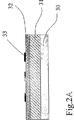
用紙1が、印刷ニップを通過して、インクを受容したならば、例えばさらなる処理のために排紙胴16によって、圧胴から運び去られる。図2Aで、ブランケット胴8のブランケット9を形成する層が詳細に述べられる。ブランケット胴8は、脂肪親和性の層31が上に付着する基盤層30を有する。さらに、脂肪親和性の層31を覆って、彫りこむことが可能な疎油性の層32が付着される。最後に、インクを塗布される版の彫り込み部の形状に正確に一致する構造33が、セレクタ胴10からインクを受容するために、疎油性の層32を覆って作られる。
Once the paper 1 has passed through the printing nip and received ink, it is carried away from the impression cylinder, for example by a
構造33は、例えば次の方法で作られる。インク胴はセレクト胴で、完全にインクを塗布され、そしてインクは版に転移する。そこで、版は、版の余剰インクを取り去るために、例えば(図1の)ワイピング胴17によってふき取られる。版胴6の各々の版の、インクを塗布されたイメージは、印刷ニップを通過する、胴6と8の間の基板、即ち用紙を用いることなく、胴6と8の回転によってコレクタ胴8に転移されて、そこで、完全な見当に合わせて、版胴6の版上のインクを塗布される彫り込み部に正確に一致する、図2Aと2Bに示された構造33を形成する。
The
異なる層が、ブランケット胴の基盤層に付着され、版の彫り込み部に一致する構造33が作られたならば、疎油性の層32は、構造33の間に脂肪親和性の層31を露出するために、例えば図2Bに示されたレーザ34のような適切な手段によって、あるいは別の相当な手段によって取り除かれる。その結果、図2Bで誇張した方法で示したように、インク35は、疎油性の層32によってはじかれて、露出させた脂肪親和性構造の層31に蓄積される。そこで、ブランケット胴8によって、版胴6の彫り込み部にインクを塗布する精度が向上し、結果として、ワイピング胴17によってふき取られるインクの量が低減する。
If different layers are applied to the base layer of the blanket cylinder and a
本発明の別の実施形態が、図3Aと3Bに関してさらに述べられる。この実施形態で、ブランケット胴8の表面を形成する層が、基盤層、疎油性の層36、及び脂肪親和性の彫り込み可能な表面層37から作られ、その上に、インクを塗布される版の彫り込み部の形状に正確に一致する構造38が作られる。構造38は、構造33(上記参照)と同様の方法で作られてもよい。適切な手段、例えばレーザ34、あるいはその他の相当する手段によって、脂肪親和性の層37は、構造38の下にあるもの以外が除去され、そこで、構造38のインクをはじく疎油性の層36を露出する。従ってこの効果は、凹版にインクを塗布する精度を向上する。
Another embodiment of the invention is further described with respect to FIGS. 3A and 3B. In this embodiment, the layer forming the surface of the blanket cylinder 8 is made up of a base layer, an
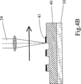
本発明の別の実施形態は、図4Aと図4Bに関して述べられる。これらの図で、ブランケット胴8は、脂肪親和性の層40を上に付着した基盤層30を包含し、この脂肪親和性の層40はさらに、インクを塗布する版の彫り込み部の形状に一致する構造41を支持している。この実施形態において、構造41が、例えば構造33又は38(上記参照)と同様の方法で作られたならば、脂肪親和性の層40は、図4Bに示した構造41の間の層40の1部分を除去するために、適切な手段によって、例えばレーザ34、あるいはその他の適切な相当手段によって、さらに彫りこまれる。
Another embodiment of the invention is described with respect to FIGS. 4A and 4B. In these figures, the blanket cylinder 8 includes a
好ましくは、脂肪親和性で疎水性の材料として使用される材料は、限定されるものではないが、ゴム組成、ケイ酸塩組成を含む。そして、疎油性の材料として、珪素組成やゴム組成を含む。勿論、これらの材料は、例示の方法によって与えられ、そして適切な特性を持ったその他の相当材料が、本発明を実施することが出来る。その他の例は、上述したフラウンフォ−ファ研究所ケイ酸研究(Fraunhofer Institut Silicatforschung)のORMOCER(登録商標)eによって公知の、ゾル-ゲル工程によって与えられる(例として、インターネットのアドレスwww.isc.fhg.deで公開されているウェブページを参照)。 Preferably, materials used as lipophilic and hydrophobic materials include, but are not limited to, rubber compositions and silicate compositions. And a silicon composition and a rubber composition are included as an oleophobic material. Of course, these materials are given by way of example, and other equivalent materials with suitable properties can implement the invention. Other examples are given by the sol-gel process known by ORMOCER® e of the Fraunhofer Institut Silicatforschung mentioned above (for example the Internet address www.isc.fhg (See web page published on .de).
また好ましくは、構造33、38又は41が、ブランケット胴8の表面に作られたならば、ブランケットの彫り込み操作は、ブランケット胴8と版胴6との間の完全な見当を維持するために、印刷機に搭載されたブランケット胴8でなされる。
Also preferably, if the
Claims (9)
少なくとも、彫りこみ可能な脂肪親和性の表面層(37;40)を備える非彫りこみブランケット(9)を前記凹版印刷機の前記ブランケット胴(8)に搭載する段階と、
前記セレクタ胴(10)を用いて、非彫りこみブランケット(9)を有する前記ブランケット胴(8)にインクを塗布する段階と、
前記ブランケット胴(8)に付着された前記インクを、前記版胴(6)に転移する段階と、
前記印刷版の前記彫り込み部の外側の余剰インクを除去するために、前記版胴(6)の表面をふき取る段階と、
インクを塗布される前記凹版構造に正確に一致する前記ブランケット(9)上の構造(38;41)を形成するために、前記版胴(6)から前記ブランケット胴(8)に再び前記インクを転移する段階と、
前記構造(38;41)によって覆われていない範囲で前記脂肪親和性の表面層(37、40)を彫りこむ段階と、
を含む、請求項1に記載のブランケット胴を製作するための方法。A method for making the blanket cylinder of claim 1, comprising:
Mounting a non-engraved blanket (9) comprising at least an engraveable lipophilic surface layer (37; 40) on the blanket cylinder (8) of the intaglio printing press;
Applying ink to the blanket cylinder (8) having a non-engraved blanket (9) using the selector cylinder (10);
Transferring the ink adhered to the blanket cylinder (8) to the plate cylinder (6);
Wiping the surface of the plate cylinder (6) to remove excess ink outside the engraved portion of the printing plate;
In order to form a structure (38; 41) on the blanket (9) that exactly matches the intaglio structure to which ink is applied, the ink is again applied from the plate cylinder (6) to the blanket cylinder (8). A transition stage;
Carving the lipophilic surface layer (37, 40) to the extent not covered by the structure (38; 41);
A method for making a blanket cylinder according to claim 1 comprising:
少なくとも、彫りこみ可能な疎油性の表面層(32)を備える非彫りこみブランケット(9)を前記凹版印刷機の前記ブランケット胴(8)に搭載する段階と、
前記セレクタ胴(10)を用いて、非彫りこみブランケット(9)を有する前記ブランケット胴(8)にインクを塗布する段階と、
前記ブランケット胴(8)に付着された前記インクを、前記版胴(6)に転移する段階と、
前記印刷版の前記彫り込み部の外側の余剰インクを除去するために、前記版胴(6)の表面をふき取る段階と、
インクを塗布される前記凹版構造に正確に一致する前記ブランケット(9)上の構造(33)を形成するために、前記版胴(6)から前記ブランケット胴(8)に再び前記インクを転移する段階と、
前記構造(33)によって覆われている範囲で前記疎油性の表面層(32)を彫りこむ段階と、
を含む、請求項3に記載のブランケット胴を製作するための方法。A method for producing the blanket cylinder according to claim 3, comprising:
Mounting a non-engraved blanket (9) comprising at least an engraveable oleophobic surface layer (32) on the blanket cylinder (8) of the intaglio printing press;
Applying ink to the blanket cylinder (8) having a non-engraved blanket (9) using the selector cylinder (10);
Transferring the ink adhered to the blanket cylinder (8) to the plate cylinder (6);
Wiping the surface of the plate cylinder (6) to remove excess ink outside the engraved portion of the printing plate;
The ink is transferred again from the plate cylinder (6) to the blanket cylinder (8) to form a structure (33) on the blanket (9) that exactly matches the intaglio structure to which ink is applied. Stages,
Carving the oleophobic surface layer (32) in a range covered by the structure (33);
A method for making a blanket cylinder as claimed in claim 3.
Applications Claiming Priority (2)
| Application Number | Priority Date | Filing Date | Title |
|---|---|---|---|
| EP03002187A EP1445098A1 (en) | 2003-02-04 | 2003-02-04 | Blanket cylinder for an intaglio printing machine |
| PCT/IB2004/000282 WO2004069539A2 (en) | 2003-02-04 | 2004-02-03 | Blanket cylinder for an intaglio printing machine |
Publications (3)
| Publication Number | Publication Date |
|---|---|
| JP2006516492A JP2006516492A (en) | 2006-07-06 |
| JP2006516492A5 JP2006516492A5 (en) | 2010-09-09 |
| JP4648301B2 true JP4648301B2 (en) | 2011-03-09 |
Family
ID=32605288
Family Applications (1)
| Application Number | Title | Priority Date | Filing Date |
|---|---|---|---|
| JP2006502397A Expired - Fee Related JP4648301B2 (en) | 2003-02-04 | 2004-02-03 | Blanket cylinder of intaglio printing machine |
Country Status (7)
| Country | Link |
|---|---|
| US (1) | US7464642B2 (en) |
| EP (2) | EP1445098A1 (en) |
| JP (1) | JP4648301B2 (en) |
| KR (1) | KR101054514B1 (en) |
| CN (1) | CN100404248C (en) |
| RU (1) | RU2326002C2 (en) |
| WO (1) | WO2004069539A2 (en) |
Families Citing this family (20)
| Publication number | Priority date | Publication date | Assignee | Title |
|---|---|---|---|---|
| RU2490136C2 (en) | 2004-01-15 | 2013-08-20 | КБА-НотаСис СА | System of ink application for gravure printing machine |
| EP2045783A1 (en) | 2007-10-02 | 2009-04-08 | Kba-Giori S.A. | Method and system for controlled production of security documents, especially banknotes |
| EP2119527A1 (en) | 2008-05-16 | 2009-11-18 | Kba-Giori S.A. | Method and system for manufacturing intaglio printing plates for the production of security papers |
| JP5859212B2 (en) * | 2011-02-14 | 2016-02-10 | 株式会社シンク・ラボラトリー | Manufacturing method of member with recess |
| EP2637396A1 (en) | 2012-03-07 | 2013-09-11 | KBA-NotaSys SA | Method of checking producibility of a composite security design of a security document on a line of production equipment and digital computer environment for implementing the same |
| BR102012016393A2 (en) | 2012-07-02 | 2015-04-07 | Rexam Beverage Can South America S A | Can printing device, can printing process, printed can and blanket |
| ES2842224T3 (en) | 2013-06-11 | 2021-07-13 | Ball Corp | Printing procedure using soft photopolymer plates |
| US9555616B2 (en) | 2013-06-11 | 2017-01-31 | Ball Corporation | Variable printing process using soft secondary plates and specialty inks |
| US10086602B2 (en) | 2014-11-10 | 2018-10-02 | Rexam Beverage Can South America | Method and apparatus for printing metallic beverage container bodies |
| ES2734983T3 (en) | 2014-12-04 | 2019-12-13 | Ball Beverage Packaging Europe Ltd | Printing apparatus |
| DE102016100371A1 (en) * | 2016-01-11 | 2017-07-13 | Ball Europe Gmbh | Device for decorating containers |
| RU2624717C1 (en) * | 2016-03-11 | 2017-07-05 | Закрытое акционерное общество "Санкт-Петербургская Образцовая Типография" | Method of tool cliche producing |
| US10549921B2 (en) | 2016-05-19 | 2020-02-04 | Rexam Beverage Can Company | Beverage container body decorator inspection apparatus |
| US11034145B2 (en) | 2016-07-20 | 2021-06-15 | Ball Corporation | System and method for monitoring and adjusting a decorator for containers |
| EP3487706A4 (en) | 2016-07-20 | 2020-04-08 | Ball Corporation | System and method for aligning an inker of a decorator |
| US10739705B2 (en) | 2016-08-10 | 2020-08-11 | Ball Corporation | Method and apparatus of decorating a metallic container by digital printing to a transfer blanket |
| MX2019001607A (en) | 2016-08-10 | 2019-11-08 | Ball Corp | Method and apparatus of decorating a metallic container by digital printing to a transfer blanket. |
| CN107128097B (en) * | 2017-06-20 | 2018-12-04 | 天津中荣印刷科技有限公司 | A kind of method that Jie's model machine carves air cushion font blanket automatically |
| DE102019216458A1 (en) * | 2019-10-25 | 2021-04-29 | Gallus Ferd. Rüesch AG | Printing system for rotary screen printing, comprising a screen printing cylinder with resilient surface elements |
| CN114211870B (en) * | 2021-12-13 | 2024-02-06 | 浦江莱迪恩斯服饰有限公司 | Velvet fabric woven cloth plane printing device and use method thereof |
Citations (2)
| Publication number | Priority date | Publication date | Assignee | Title |
|---|---|---|---|---|
| JPH09511711A (en) * | 1995-08-04 | 1997-11-25 | インターナシヨナル・ビジネス・マシーンズ・コーポレーシヨン | Lithographic surface or thin layer modification |
| JP2000127351A (en) * | 1998-08-21 | 2000-05-09 | Komori Corp | Intaglio printer |
Family Cites Families (19)
| Publication number | Priority date | Publication date | Assignee | Title |
|---|---|---|---|---|
| US2099024A (en) | 1933-11-08 | 1937-11-16 | Vulcan Proofing Company | Draw sheet for rotary printing presses |
| DE644341C (en) * | 1933-11-08 | 1937-04-29 | Vulcan Proofing Company | Upper cover for impression cylinder lifts |
| GB762423A (en) * | 1954-07-12 | 1956-11-28 | Timsons Ltd | Improvements in or relating to impression cylinders for rotary printing machines |
| US3991673A (en) * | 1972-08-02 | 1976-11-16 | St. Regis Paper Company | Nonfabric engraving blanket |
| US4479432A (en) * | 1980-05-15 | 1984-10-30 | Toppan Printing Co., Ltd. | Thick film printing method |
| AU550695B2 (en) * | 1982-04-07 | 1986-03-27 | De La Rue Giori S.A. | Copperplate engraving machine for paper currency |
| EP0406157B1 (en) * | 1989-06-29 | 1994-05-18 | De La Rue Giori S.A. | Platen printing machine for printing security paper |
| US5352507A (en) * | 1991-04-08 | 1994-10-04 | W. R. Grace & Co.-Conn. | Seamless multilayer printing blanket |
| EP0563007B1 (en) | 1992-03-26 | 1996-07-10 | De La Rue Giori S.A. | Intaglio printing machine |
| FR2748422B1 (en) * | 1996-05-10 | 1998-06-12 | Rollin Sa | SYSTEM FOR TRANSFERRING A MORE OR LESS VISCOUS LIQUID PRODUCT ONTO A MEDIUM, METHOD FOR MANUFACTURING SUCH A SURFACE AND OFFSET PRINTING BLANKET PRODUCED WITH THIS SURFACE |
| US5908505A (en) * | 1996-09-10 | 1999-06-01 | Questech, Inc. | High volume, textured liquid transfer surface |
| CA2232695C (en) | 1997-04-14 | 2005-02-01 | De La Rue Giori S.A. | Intaglio printing press |
| JPH11188852A (en) * | 1997-12-26 | 1999-07-13 | Komori Corp | Intaglio printing machine |
| JP2000255178A (en) * | 1999-03-10 | 2000-09-19 | Canon Inc | Printing blanket and manufacture thereof |
| JP2000326654A (en) * | 1999-05-24 | 2000-11-28 | Sumitomo Rubber Ind Ltd | Manufacture of blanket for printing |
| JP2001260563A (en) * | 2000-03-17 | 2001-09-25 | Dainippon Printing Co Ltd | Blanket |
| JP2001277465A (en) * | 2000-03-31 | 2001-10-09 | Fuji Photo Film Co Ltd | Lithographic printing machine and lithographic printing method |
| EP1164011A3 (en) * | 2000-06-16 | 2005-09-14 | ROSSINI S.p.A. | Multi-layered printing sleeve |
| US6997108B2 (en) * | 2001-08-21 | 2006-02-14 | Mitsubishi Heavy Industries, Ltd. | Plate-making type printing press, multi-color printing press and plate-making type printing method |
-
2003
- 2003-02-04 EP EP03002187A patent/EP1445098A1/en not_active Withdrawn
-
2004
- 2004-02-03 US US10/543,462 patent/US7464642B2/en not_active Expired - Fee Related
- 2004-02-03 EP EP04707591A patent/EP1590177B1/en not_active Expired - Lifetime
- 2004-02-03 KR KR1020057014211A patent/KR101054514B1/en not_active IP Right Cessation
- 2004-02-03 WO PCT/IB2004/000282 patent/WO2004069539A2/en active Application Filing
- 2004-02-03 CN CNB2004800034905A patent/CN100404248C/en not_active Expired - Fee Related
- 2004-02-03 RU RU2005127582/12A patent/RU2326002C2/en not_active IP Right Cessation
- 2004-02-03 JP JP2006502397A patent/JP4648301B2/en not_active Expired - Fee Related
Patent Citations (2)
| Publication number | Priority date | Publication date | Assignee | Title |
|---|---|---|---|---|
| JPH09511711A (en) * | 1995-08-04 | 1997-11-25 | インターナシヨナル・ビジネス・マシーンズ・コーポレーシヨン | Lithographic surface or thin layer modification |
| JP2000127351A (en) * | 1998-08-21 | 2000-05-09 | Komori Corp | Intaglio printer |
Also Published As
| Publication number | Publication date |
|---|---|
| US7464642B2 (en) | 2008-12-16 |
| KR101054514B1 (en) | 2011-08-05 |
| KR20050098289A (en) | 2005-10-11 |
| CN100404248C (en) | 2008-07-23 |
| EP1590177B1 (en) | 2012-08-22 |
| EP1445098A1 (en) | 2004-08-11 |
| US20060243146A1 (en) | 2006-11-02 |
| RU2326002C2 (en) | 2008-06-10 |
| WO2004069539A2 (en) | 2004-08-19 |
| CN1747834A (en) | 2006-03-15 |
| RU2005127582A (en) | 2006-01-20 |
| JP2006516492A (en) | 2006-07-06 |
| WO2004069539A3 (en) | 2005-04-28 |
| EP1590177A2 (en) | 2005-11-02 |
Similar Documents
| Publication | Publication Date | Title |
|---|---|---|
| JP4648301B2 (en) | Blanket cylinder of intaglio printing machine | |
| JP2006516492A5 (en) | ||
| JP4871120B2 (en) | Intaglio printing machine | |
| JP5540143B2 (en) | Ink supply system for intaglio printing press | |
| USRE41048E1 (en) | Combined Lithographic/flexographic printing apparatus and process | |
| EP3283296B1 (en) | Variable printing process using flexible secondary plates and specialty inks | |
| US20070181016A1 (en) | Printing machine | |
| EP2384890B1 (en) | Impression cylinder for intaglio printing and intaglio printing process | |
| EP1602483A1 (en) | Intaglio printing machine and process | |
| EP3619045B1 (en) | Inking system for inking an intaglio printing cylinder of an intaglio printing press, intaglio printing press comprising the same, and process of inking such an intaglio printing cylinder | |
| WO2007130657A2 (en) | Coating device | |
| KR20060104694A (en) | Intaglio offset printing machine | |
| CA2523834A1 (en) | Offset printing press | |
| JP2001191495A (en) | Coating roller for printing intaglio and manufacturing method for the same | |
| US662853A (en) | Method of printing and making printing-forms. | |
| JPS625793B2 (en) |
Legal Events
| Date | Code | Title | Description |
|---|---|---|---|
| A621 | Written request for application examination |
Free format text: JAPANESE INTERMEDIATE CODE: A621 Effective date: 20070202 |
|
| A131 | Notification of reasons for refusal |
Free format text: JAPANESE INTERMEDIATE CODE: A131 Effective date: 20100202 |
|
| A601 | Written request for extension of time |
Free format text: JAPANESE INTERMEDIATE CODE: A601 Effective date: 20100430 |
|
| A602 | Written permission of extension of time |
Free format text: JAPANESE INTERMEDIATE CODE: A602 Effective date: 20100512 |
|
| A521 | Request for written amendment filed |
Free format text: JAPANESE INTERMEDIATE CODE: A523 Effective date: 20100722 |
|
| A524 | Written submission of copy of amendment under article 19 pct |
Free format text: JAPANESE INTERMEDIATE CODE: A524 Effective date: 20100722 |
|
| A131 | Notification of reasons for refusal |
Free format text: JAPANESE INTERMEDIATE CODE: A131 Effective date: 20100907 |
|
| A521 | Request for written amendment filed |
Free format text: JAPANESE INTERMEDIATE CODE: A523 Effective date: 20101014 |
|
| TRDD | Decision of grant or rejection written | ||
| A01 | Written decision to grant a patent or to grant a registration (utility model) |
Free format text: JAPANESE INTERMEDIATE CODE: A01 Effective date: 20101109 |
|
| A01 | Written decision to grant a patent or to grant a registration (utility model) |
Free format text: JAPANESE INTERMEDIATE CODE: A01 |
|
| A61 | First payment of annual fees (during grant procedure) |
Free format text: JAPANESE INTERMEDIATE CODE: A61 Effective date: 20101209 |
|
| FPAY | Renewal fee payment (event date is renewal date of database) |
Free format text: PAYMENT UNTIL: 20131217 Year of fee payment: 3 |
|
| R150 | Certificate of patent or registration of utility model |
Ref document number: 4648301 Country of ref document: JP Free format text: JAPANESE INTERMEDIATE CODE: R150 Free format text: JAPANESE INTERMEDIATE CODE: R150 |
|
| FPAY | Renewal fee payment (event date is renewal date of database) |
Free format text: PAYMENT UNTIL: 20131217 Year of fee payment: 3 |
|
| S531 | Written request for registration of change of domicile |
Free format text: JAPANESE INTERMEDIATE CODE: R313531 |
|
| S533 | Written request for registration of change of name |
Free format text: JAPANESE INTERMEDIATE CODE: R313533 |
|
| FPAY | Renewal fee payment (event date is renewal date of database) |
Free format text: PAYMENT UNTIL: 20131217 Year of fee payment: 3 |
|
| R350 | Written notification of registration of transfer |
Free format text: JAPANESE INTERMEDIATE CODE: R350 |
|
| R250 | Receipt of annual fees |
Free format text: JAPANESE INTERMEDIATE CODE: R250 |
|
| R250 | Receipt of annual fees |
Free format text: JAPANESE INTERMEDIATE CODE: R250 |
|
| R250 | Receipt of annual fees |
Free format text: JAPANESE INTERMEDIATE CODE: R250 |
|
| R250 | Receipt of annual fees |
Free format text: JAPANESE INTERMEDIATE CODE: R250 |
|
| R250 | Receipt of annual fees |
Free format text: JAPANESE INTERMEDIATE CODE: R250 |
|
| R250 | Receipt of annual fees |
Free format text: JAPANESE INTERMEDIATE CODE: R250 |
|
| R250 | Receipt of annual fees |
Free format text: JAPANESE INTERMEDIATE CODE: R250 |
|
| LAPS | Cancellation because of no payment of annual fees |