JP4645853B2 - Method of deforming cross section of coated metal plate by laser beam and painted metal plate having this kind of cross section deformation - Google Patents
Method of deforming cross section of coated metal plate by laser beam and painted metal plate having this kind of cross section deformation Download PDFInfo
- Publication number
- JP4645853B2 JP4645853B2 JP2006551771A JP2006551771A JP4645853B2 JP 4645853 B2 JP4645853 B2 JP 4645853B2 JP 2006551771 A JP2006551771 A JP 2006551771A JP 2006551771 A JP2006551771 A JP 2006551771A JP 4645853 B2 JP4645853 B2 JP 4645853B2
- Authority
- JP
- Japan
- Prior art keywords
- cross
- metal plate
- sectional deformation
- laser beam
- laser
- Prior art date
- Legal status (The legal status is an assumption and is not a legal conclusion. Google has not performed a legal analysis and makes no representation as to the accuracy of the status listed.)
- Active
Links
- 239000002184 metal Substances 0.000 title claims abstract description 101
- 229910052751 metal Inorganic materials 0.000 title claims abstract description 101
- 238000000034 method Methods 0.000 title claims abstract description 36
- 238000003466 welding Methods 0.000 claims abstract description 10
- 229910000831 Steel Inorganic materials 0.000 claims description 13
- 239000010959 steel Substances 0.000 claims description 13
- 238000003672 processing method Methods 0.000 claims description 3
- 125000006850 spacer group Chemical group 0.000 abstract description 17
- 239000000463 material Substances 0.000 abstract description 13
- 239000011248 coating agent Substances 0.000 abstract description 12
- 238000000576 coating method Methods 0.000 abstract description 12
- 238000009834 vaporization Methods 0.000 abstract description 3
- 230000008016 vaporization Effects 0.000 abstract description 3
- 239000002360 explosive Substances 0.000 abstract description 2
- 238000012986 modification Methods 0.000 abstract 2
- 230000004048 modification Effects 0.000 abstract 2
- 238000009835 boiling Methods 0.000 abstract 1
- 239000007769 metal material Substances 0.000 abstract 1
- 230000005855 radiation Effects 0.000 abstract 1
- 238000007493 shaping process Methods 0.000 abstract 1
- 230000007797 corrosion Effects 0.000 description 8
- 238000005260 corrosion Methods 0.000 description 8
- 239000000155 melt Substances 0.000 description 6
- 238000002844 melting Methods 0.000 description 4
- 230000008018 melting Effects 0.000 description 4
- 238000010438 heat treatment Methods 0.000 description 3
- 230000003993 interaction Effects 0.000 description 3
- 238000002156 mixing Methods 0.000 description 3
- 239000003973 paint Substances 0.000 description 3
- 238000003825 pressing Methods 0.000 description 3
- 238000011282 treatment Methods 0.000 description 3
- 230000015572 biosynthetic process Effects 0.000 description 2
- 230000035515 penetration Effects 0.000 description 2
- 229910000794 TRIP steel Inorganic materials 0.000 description 1
- HCHKCACWOHOZIP-UHFFFAOYSA-N Zinc Chemical compound [Zn] HCHKCACWOHOZIP-UHFFFAOYSA-N 0.000 description 1
- 230000000295 complement effect Effects 0.000 description 1
- 238000010276 construction Methods 0.000 description 1
- 238000011161 development Methods 0.000 description 1
- 230000018109 developmental process Effects 0.000 description 1
- 238000003618 dip coating Methods 0.000 description 1
- 230000000694 effects Effects 0.000 description 1
- 238000009713 electroplating Methods 0.000 description 1
- 230000001747 exhibiting effect Effects 0.000 description 1
- 238000005286 illumination Methods 0.000 description 1
- 230000001678 irradiating effect Effects 0.000 description 1
- 238000005304 joining Methods 0.000 description 1
- 238000013532 laser treatment Methods 0.000 description 1
- 238000003754 machining Methods 0.000 description 1
- 238000004519 manufacturing process Methods 0.000 description 1
- 238000010309 melting process Methods 0.000 description 1
- 230000003287 optical effect Effects 0.000 description 1
- 238000005457 optimization Methods 0.000 description 1
- 238000010422 painting Methods 0.000 description 1
- 230000000149 penetrating effect Effects 0.000 description 1
- 230000002093 peripheral effect Effects 0.000 description 1
- 229910001220 stainless steel Inorganic materials 0.000 description 1
- 229910052725 zinc Inorganic materials 0.000 description 1
- 239000011701 zinc Substances 0.000 description 1
Images
Classifications
-
- B—PERFORMING OPERATIONS; TRANSPORTING
- B23—MACHINE TOOLS; METAL-WORKING NOT OTHERWISE PROVIDED FOR
- B23K—SOLDERING OR UNSOLDERING; WELDING; CLADDING OR PLATING BY SOLDERING OR WELDING; CUTTING BY APPLYING HEAT LOCALLY, e.g. FLAME CUTTING; WORKING BY LASER BEAM
- B23K26/00—Working by laser beam, e.g. welding, cutting or boring
- B23K26/20—Bonding
- B23K26/21—Bonding by welding
- B23K26/24—Seam welding
- B23K26/244—Overlap seam welding
-
- B—PERFORMING OPERATIONS; TRANSPORTING
- B23—MACHINE TOOLS; METAL-WORKING NOT OTHERWISE PROVIDED FOR
- B23K—SOLDERING OR UNSOLDERING; WELDING; CLADDING OR PLATING BY SOLDERING OR WELDING; CUTTING BY APPLYING HEAT LOCALLY, e.g. FLAME CUTTING; WORKING BY LASER BEAM
- B23K26/00—Working by laser beam, e.g. welding, cutting or boring
- B23K26/20—Bonding
- B23K26/32—Bonding taking account of the properties of the material involved
-
- B—PERFORMING OPERATIONS; TRANSPORTING
- B23—MACHINE TOOLS; METAL-WORKING NOT OTHERWISE PROVIDED FOR
- B23K—SOLDERING OR UNSOLDERING; WELDING; CLADDING OR PLATING BY SOLDERING OR WELDING; CUTTING BY APPLYING HEAT LOCALLY, e.g. FLAME CUTTING; WORKING BY LASER BEAM
- B23K26/00—Working by laser beam, e.g. welding, cutting or boring
- B23K26/60—Preliminary treatment
-
- B—PERFORMING OPERATIONS; TRANSPORTING
- B23—MACHINE TOOLS; METAL-WORKING NOT OTHERWISE PROVIDED FOR
- B23K—SOLDERING OR UNSOLDERING; WELDING; CLADDING OR PLATING BY SOLDERING OR WELDING; CUTTING BY APPLYING HEAT LOCALLY, e.g. FLAME CUTTING; WORKING BY LASER BEAM
- B23K2101/00—Articles made by soldering, welding or cutting
- B23K2101/18—Sheet panels
- B23K2101/185—Tailored blanks
-
- B—PERFORMING OPERATIONS; TRANSPORTING
- B23—MACHINE TOOLS; METAL-WORKING NOT OTHERWISE PROVIDED FOR
- B23K—SOLDERING OR UNSOLDERING; WELDING; CLADDING OR PLATING BY SOLDERING OR WELDING; CUTTING BY APPLYING HEAT LOCALLY, e.g. FLAME CUTTING; WORKING BY LASER BEAM
- B23K2101/00—Articles made by soldering, welding or cutting
- B23K2101/34—Coated articles, e.g. plated or painted; Surface treated articles
-
- B—PERFORMING OPERATIONS; TRANSPORTING
- B23—MACHINE TOOLS; METAL-WORKING NOT OTHERWISE PROVIDED FOR
- B23K—SOLDERING OR UNSOLDERING; WELDING; CLADDING OR PLATING BY SOLDERING OR WELDING; CUTTING BY APPLYING HEAT LOCALLY, e.g. FLAME CUTTING; WORKING BY LASER BEAM
- B23K2103/00—Materials to be soldered, welded or cut
- B23K2103/08—Non-ferrous metals or alloys
-
- B—PERFORMING OPERATIONS; TRANSPORTING
- B23—MACHINE TOOLS; METAL-WORKING NOT OTHERWISE PROVIDED FOR
- B23K—SOLDERING OR UNSOLDERING; WELDING; CLADDING OR PLATING BY SOLDERING OR WELDING; CUTTING BY APPLYING HEAT LOCALLY, e.g. FLAME CUTTING; WORKING BY LASER BEAM
- B23K2103/00—Materials to be soldered, welded or cut
- B23K2103/50—Inorganic material, e.g. metals, not provided for in B23K2103/02 – B23K2103/26
Landscapes
- Engineering & Computer Science (AREA)
- Physics & Mathematics (AREA)
- Optics & Photonics (AREA)
- Plasma & Fusion (AREA)
- Mechanical Engineering (AREA)
- Laser Beam Processing (AREA)
Abstract
Description
本発明は、請求項1の前段部分に記載の塗装金属板のレーザ加工法と、請求項8又は10の前段部分に記載の塗装金属板とに関する。この一般的な種類の方法及び金属板は特許文献1から既に知られている。 The present invention relates to a laser processing method for a coated metal plate according to the first part of claim 1 and a painted metal plate according to the first part of claim 8 or 10. This general type of method and metal plate are already known from US Pat.
多くの塗装金属板の場合、特に自動車工業において用いられる電気亜鉛めっき金属板又は亜鉛引き金属板の場合、塗装材料は金属板材料の融点よりも遥かに低い融点を有している。このため、この種の金属板をレーザ溶接する際、重ね合わせ接合部に塗装材料の爆発的な気化が生起する可能性があり、これは接合品質を大きく損なう。 In the case of many coated metal plates, especially in the case of electrogalvanized or galvanized metal plates used in the automotive industry, the coating material has a melting point that is much lower than the melting point of the metal plate material. For this reason, when this kind of metal plate is laser-welded, explosive vaporization of the coating material may occur at the overlap joint, which greatly impairs the joint quality.
この接合品質を改善するため、気化した塗装材料が漏出し得るように、金属板の間に狭い間隙を形成するスペーサを用いる方式が既に提案されている。特許文献2によれば、表面にレーザ照射することによって適切なクレータ状のスペーサを生成することができる。特許文献1によれば、パルス化されたレーザビームを用いて、瘤状のスペーサを作ることができる。スペーサの幾何学的形状を変化させる可能性については開示されていない。 In order to improve the bonding quality, a method using a spacer that forms a narrow gap between the metal plates has been proposed so that the vaporized coating material can leak out. According to Patent Document 2, an appropriate crater-like spacer can be generated by irradiating the surface with laser. According to Patent Document 1, it is possible to make a knob-like spacer using a pulsed laser beam. The possibility of changing the spacer geometry is not disclosed.
これら先行技術の基本的な欠点は、この方法で生成されるスペーサがどちらかといえば点に近いことである。その結果、スペーサが―印加する力に応じて―比較的容易に隣接する金属板の中に侵入したり、あるいはそれ自体が変形したりして、金属板の間隔に好ましくない偏りが生じる。薄い金属板の場合には、瘤状のスペーサが、スペーサを挟む金属板の反対側の面に盛り上がったような印象を与える可能性がある。 The basic drawback of these prior arts is that the spacers produced by this method are rather close to point. As a result, depending on the force applied by the spacer, it easily enters the adjacent metal plate or deforms itself, resulting in an unfavorable bias in the interval between the metal plates. In the case of a thin metal plate, there is a possibility that the knob-shaped spacer gives an impression that the surface on the opposite side of the metal plate sandwiching the spacer is raised.
本発明の課題は、金属板の間隔設定における偏差をスペーサの形状の適正化によって減少させることにある。 The subject of this invention is reducing the deviation in the space | interval setting of a metal plate by optimization of the shape of a spacer.
本発明は、提案する方法及び適切な金属板に関して、請求項1の特徴部分と請求項8の特徴部分とに開示されている。これ以外の請求項は、本発明の方法(請求項2〜6)と金属板(請求項9,10)との有利な実施形態及び他の発展形態を述べている。 The invention is disclosed in the characterizing part of claim 1 and in the characterizing part of claim 8 with regard to the proposed method and a suitable metal plate. The other claims describe advantageous embodiments and other developments of the method according to the invention (claims 2 to 6) and the metal plate (claims 9 and 10 ).
提案する方法に関しては、本発明の課題は、少なくとも1枚の塗装金属板の少なくとも1つの面に、本発明に従って、レーザによって、表面から突出する少なくとも1つの断面変形(断層変形)を生成することによって解決される。この場合、レーザビームを、塗装金属板の表面上で円周を描くように動かすことによって、少なくとも1つの断面変形を生成する。 With respect to the proposed method, the object of the present invention is to generate at least one cross-sectional deformation (fault deformation) projecting from the surface by means of a laser in accordance with the present invention on at least one surface of at least one painted metal plate. Solved by. In this case, at least one cross-sectional deformation is generated by moving the laser beam to draw a circle on the surface of the painted metal plate .
この構成法の利点は、レーザビームの動きが溶融物の相互作用領域の範囲内で生起するので、加熱によって誘起される混合に加えて、その動きが溶融物を活性化してほとんど攪拌に近い作用を及ぼす点にある。この結果、得られる断面変形は、その頂部において一層「球面」形状のものとなり、断面変形の高さよりも大きな頂部半径を呈することになる。この形式の断面変形は、スペーサとして先行技術のものより遥かに適している。球面形状であるために、反対側の金属板の中に押入したり、あるいはそれ自体変形したりする可能性が低く、従って金属板の間隔に好ましくない偏差がほとんど生じないからである。これ以外にも、薄い金属板の場合でも、断面変形によって、間隔を挟む金属板の反対側の面に押圧の印影が生じることはない。さらに、本発明の方法によって生成された断面変形を備えた塗装金属板は、先行技術の方法によって作られるものに比べてより高い耐腐食性を有する。一方では、球面状の頂部は間隔を挟んで配置される金属板の中に侵入する可能性が低く、従ってその塗装を損傷することもほとんどないかあるいは全くない。他方、突出する断面変形の材料は金属板の凹み部分から形成されるが、この凹み部分の形状は、先行技術の方法によって作られるものよりも基本的に遥かに平坦であり、従って水分を滞留させる傾向も小さい(低毛管効果)。 The advantage of this construction method is that the movement of the laser beam takes place within the melt interaction area, so that in addition to heating-induced mixing, the movement activates the melt and is almost agitated. It is in the point that affects. As a result, the resulting cross-sectional deformation is of a more “spherical” shape at the top, exhibiting a top radius that is greater than the height of the cross-sectional deformation. This type of cross-sectional deformation is much more suitable as a spacer than in the prior art. This is because the spherical shape makes it less likely to be pushed into the opposite metal plate or to deform itself, and therefore there is almost no undesirable deviation in the distance between the metal plates. In addition to this, even in the case of a thin metal plate, the imprint of pressing does not occur on the surface on the opposite side of the metal plate across the interval due to cross-sectional deformation. Furthermore, painted metal sheets with cross-sectional deformation produced by the method of the present invention have higher corrosion resistance than those made by prior art methods. On the one hand, the spherical top is unlikely to penetrate into a metal plate that is spaced apart, and therefore has little or no damage to the coating. On the other hand, the protruding cross-sectional deformation material is formed from a recessed portion of the metal plate, but the shape of this recessed portion is essentially much flatter than that produced by prior art methods and thus retains moisture. The tendency to make it small (low capillary effect).
レーザビームを、走査装置によって表面上に導くことが特に望ましい。走査装置は、特に急速かつ柔軟なビームの屈折装置、例えばミラー装置(少なくとも1つ又は複数個の操作制御可能な回転ミラーを含む)あるいは又音響光学的変調器である。 It is particularly desirable to direct the laser beam onto the surface by a scanning device. The scanning device is in particular a rapid and flexible beam refracting device, such as a mirror device (including at least one or more controllable rotating mirrors) or also an acousto-optic modulator.
特開平11−47967号公報に提案されている方法に比べた場合の本発明の大きな利点は、走査装置が金属板の表面に対して均等に動き、それによって、走査装置がレーザビームを短い処理時間だけ処理表面域上に照射し、続いてきわめて急速に別の処理表面域に移っていくという点にある。これによって、レーザビームの位置決めに必要な時間はほとんど完全に不要になり、その結果、レーザ装置の利用度を非常に高めることができる。これに対して、例えば特開平11−47967号公報に用いられる装置のような従来型のレーザ装置の場合には、レーザビームが固定のレンズ系によって処理表面に照射される。別の処理表面域に移るためには、レンズ系を構成部品に対して移動しなければならず、この移動時間の間はレーザのスイッチを切らなければならない。本発明の場合は、さらに、断面変形の形態及び配置を、レーザ走査器の処理領域内で自由にプログラムすることができる。固定のレンズ系に比較して、レーザ走査器は、個別の各断面変形に対して再位置決めする必要がなく、むしろ、断面変形の間の光学経路に沿って有利に動かすことができる。この違いは、処理時間の非常に大きな差異を生み出す。すなわち、レーザ走査器を用いると、約0.3秒で30個の適切な断面変形を生成することが可能であるが、従来型の装置の場合は、約10倍の処理時間を要する上に、さらに動きの可能な径路に関しても大幅な制約を受けるのである。然るに、走査装置の場合は、これに対して、ビームを、本発明のあらゆる動きの径路に沿って容易かつきわめて迅速に操作することができる。 The great advantage of the present invention over the method proposed in Japanese Patent Application Laid-Open No. 11-47967 is that the scanning device moves evenly with respect to the surface of the metal plate, so that the scanning device processes the laser beam in a short way. The treatment surface area is irradiated for a time, and then moves to another treatment surface area very rapidly. As a result, the time required for positioning the laser beam is almost completely unnecessary, and as a result, the utilization of the laser device can be greatly increased. On the other hand, in the case of a conventional laser device such as the device used in Japanese Patent Application Laid-Open No. 11-47967, the processing surface is irradiated with a fixed lens system. To move to another processing surface area, the lens system must be moved relative to the component, and the laser must be switched off during this movement time. In the case of the present invention, the shape and arrangement of the cross-sectional deformation can be freely programmed in the processing region of the laser scanner. Compared to a fixed lens system, the laser scanner does not need to be repositioned for each individual cross-sectional deformation, but rather can be moved advantageously along the optical path during the cross-sectional deformation. This difference creates a very large difference in processing time. That is, when a laser scanner is used, it is possible to generate 30 appropriate cross-sectional deformations in about 0.3 seconds, but in the case of a conventional apparatus, about 10 times the processing time is required. In addition, there are significant restrictions on the paths that can be moved. However, in the case of a scanning device, on the other hand, the beam can be easily and very quickly manipulated along any movement path of the present invention.
本発明の方法の1つの有利な実施形態においては、少なくとも1枚の金属板が高張力鋼である。この高張力鋼という用語は、>350MPaの引張強さを有する鋼、特に、TRIP鋼及び二相鋼(例えばTRIP700、DP600)を指している。試験の結果、先行技術の方法によっては、この種の高張力鋼にスペーサとして有効な断面変形を形成することは不可能であることが判明した。しかし、本発明の方法によればこれが可能になるのである。 In one advantageous embodiment of the method of the invention, the at least one metal plate is high strength steel. The term high strength steel refers to steels having a tensile strength of> 350 MPa, in particular TRIP steels and duplex stainless steels (eg TRIP700, DP600). Tests have shown that it is not possible to form effective cross-sectional deformations as spacers in this type of high strength steel by prior art methods. However, this is possible with the method of the present invention.
本発明の方法の他の有利な実施形態においては、レーザビームを、その出力及び/又は速度変化に関して不連続に制御する。すなわち、ビームの出力及び/又はビームを導く速度は全処理時間中一定ではなく、少なくとも2つの異なる値を有する。例えば、レーザビームの出力は、断面変形を生成する動きの当初には高められ、終期には低くされる。その代わりに、処理中心の近傍における速度は、周辺部よりも低く制御される。金属板のレーザ処理をこのように変化させることによって、断面変形の幾何学的形状の違いを制御し得る結果も得られる。 In another advantageous embodiment of the method according to the invention, the laser beam is controlled discontinuously with respect to its power and / or speed variation. That is, the power of the beam and / or the speed at which the beam is guided is not constant during the entire processing time and has at least two different values. For example, the power of the laser beam is increased at the beginning of the movement that creates the cross-sectional deformation and lowered at the end. Instead, the speed in the vicinity of the processing center is controlled to be lower than in the peripheral part. By changing the laser treatment of the metal plate in this way, the result of being able to control the difference in cross-sectional deformation geometry is also obtained.
本発明の方法の1つの有利な実施形態においては、レーザビームの焦点を表面に合わせない。焦点は、レーザの照明面積が焦点面積を少なくとも50%だけ、好ましくは200%だけ超過するように、被処理金属板の表面から離して位置させることが好ましい。このように表面加熱すると、塗装及び金属板の溶融過程が均質化され、適切な断面変形の形成が促進される。 In one advantageous embodiment of the method of the invention, the laser beam is not focused on the surface. The focal point is preferably positioned away from the surface of the metal plate to be treated so that the illumination area of the laser exceeds the focal area by at least 50%, preferably by 200%. When the surface is heated in this way, the coating and the melting process of the metal plate are homogenized, and the formation of an appropriate cross-sectional deformation is promoted.
本発明の方法のさらに他の1つの有利な実施形態においては、レーザビームの動きが、楕円、ロゼット形状、又はフェルマー螺旋の図形を描く。この最後の図形は、次の極方程式(1)、すなわち、
r2=a2θ (1)
(但し式中、r=半径、θ=極角度、a=定数)によって記述される。レーザビームをこのような図形に沿って導くと、結果的に適切な「球面」形状の断面変形が得られるという点で有利である。
In yet another advantageous embodiment of the method according to the invention, the movement of the laser beam describes an ellipse, a rosette shape or a Fermat spiral graphic. This last figure is the following polar equation (1):
r 2 = a 2 θ (1)
(Where r = radius, θ = polar angle, a = constant). Directing the laser beam along such a figure is advantageous in that it results in a suitable “spherical” shaped cross-sectional deformation.
本発明の方法のさらに他の1つの有利な実施形態においては、レーザビームが、少なくとも1つの断面変形を、少なくとも1枚の金属板の反対側の面に生成する。これは、レーザビームがこの金属板をその処理表面域の領域において溶融貫通することによって行われる。このために、溶融貫通するまでの十分な処理時間がプログラムされるか、あるいは、処理時間を制御する貫通センサが設けられる。この実施形態によって、複数の金属板を合わせて溶接する場合に、加工工程をさらに加速させることが可能になる。特開平11−47967号公報による方法においては、最初に1枚の金属板の面を出して、この金属板に断面変形を加工導入し、その後、別の金属板を持ってきて最初の金属板に重ね合わせ、次いで両者を一緒に押圧して、溶接する。しかし、両金属板を互いに対して押圧することなく重ね合わせることはさらに有利である。一緒に押圧することがないので、ほとんどの用途に対して十分な金属板間の最少間隙が残存する。しかし、これは適切な位置決め装置によっても実現することができる。本発明による方法のこの有利な実施形態においては、その後、1枚の金属板又は両金属板を貫通して断面変形を加工導入し、引き続いて、その金属板を一緒に押圧して相互に溶接する。断面変形の生成に用いる利用可能な走査装置の高速性を考慮すると、位置決め過程における節約が大幅な時間の節減を意味している。 In yet another advantageous embodiment of the inventive method, the laser beam produces at least one cross-sectional deformation on the opposite surface of the at least one metal plate. This is done by the laser beam melting and penetrating the metal plate in the region of the treated surface area. For this purpose, a sufficient processing time until melting and penetration is programmed, or a penetration sensor for controlling the processing time is provided. According to this embodiment, when a plurality of metal plates are welded together, the machining process can be further accelerated. In the method according to Japanese Patent Application Laid-Open No. 11-47967, the surface of one metal plate is first brought out, a cross-sectional deformation is introduced into this metal plate, and then another metal plate is brought to the first metal plate. Are then pressed together and welded together. However, it is further advantageous to superimpose both metal plates without pressing against each other. Since there is no pressing together, there remains a minimum gap between the metal plates sufficient for most applications. However, this can also be achieved with a suitable positioning device. In this advantageous embodiment of the method according to the invention, a cross-sectional deformation is subsequently introduced through one or both metal plates and subsequently pressed together to weld them together. To do. Considering the high speed of available scanning devices used to generate the cross-sectional deformation, the savings in the positioning process represent a significant time savings.
本発明の方法のさらに他の1つの有利な実施形態においては、少なくとも1枚の追加的な金属板を、少なくとも1つの突出した断面変形が少なくとも2枚の金属板の間に間隙を形成するように、かつ、少なくとも2枚の金属板を少なくとも1つの間隙の領域において相互に溶接するように、少なくとも1枚の塗装金属板と接触させる。この溶接は、溶接中に発生する気化生成物が少なくとも1つの間隙を通って漏出し得るように行われる。気化生成物の漏出が可能であるので、溶接線の十分に高度な品質が確保される。 In yet another advantageous embodiment of the method of the invention, at least one additional metal plate is arranged such that at least one protruding cross-sectional deformation forms a gap between at least two metal plates. In addition, at least two metal plates are brought into contact with at least one painted metal plate so as to be welded to each other in the region of at least one gap. The welding is performed so that vaporized products generated during the welding can leak through at least one gap. Since leakage of vaporized products is possible, a sufficiently high quality of the weld line is ensured.
本発明の方法のもう1つ他の有利な実施形態においては、少なくとも2枚の金属板を、溶接の継手が、結果的に、先行して生成された少なくとも1つの断面変形の上に少なくとも部分的に溶接されるように相互に溶接する。 In another advantageous embodiment of the method according to the invention, the at least two metal plates are welded at least partly over the at least one previously produced cross-sectional deformation. Weld each other so that they are welded together.
この種の断面変形のそれぞれは塗装の損傷を表している。というのは、レーザ照射の結果として塗装が気化し、金属板の母材が残っているからである。自動車の製造においては、特に亜鉛の塗装(電気めっき)が腐食防止に役立っている。塗装の損傷はそれぞれ腐食の核となることを意味する場合がある。しかし、溶接線もこの種の損傷を意味するが、接合をなくすわけにはいかない。溶接線を断面変形の上に走らせて、少なくとも部分的にこれと置き換えることによって、可能性のある腐食の核の数を減らすことができ、これによって腐食の危険性が低減する。後続の防食処理のために、特に電気亜鉛めっきのために、断面変形の形状は決定的に重要である。本発明によれば、なだらかな輪郭の山の頂点が形成され、特開平11−47967号公報によれば、クレータが形成される。山の頂点は、同量の材料によって形成されるクレータよりも表面積が小さく、従って、腐食に曝される面積も小さくなる。さらに、山の頂点は、接合金属板の場合にもすべての側面から電気めっきすることが可能であるが、クレータはその上に載せられる金属板によってカバーされてしまうので内側を電気めっきすることができない。金属板接合後のクレータの内部には湿気が残留し得ることになり、断面変形が腐食の核になる。 Each of these types of cross-sectional deformation represents paint damage. This is because the coating is vaporized as a result of the laser irradiation, and the base material of the metal plate remains. In automobile production, zinc coating (electroplating) is particularly useful for preventing corrosion. Each paint damage may mean a core of corrosion. However, weld lines also mean this type of damage, but it cannot be eliminated. By running the weld line over the cross-sectional deformation and at least partially replacing it, the number of possible corrosion nuclei can be reduced, thereby reducing the risk of corrosion. The shape of the cross-sectional deformation is critical for the subsequent anticorrosion treatment, especially for electrogalvanizing. According to the present invention, the peak of a mountain having a gentle outline is formed, and according to Japanese Patent Laid-Open No. 11-47967, a crater is formed. The crest of the mountain has a smaller surface area than a crater formed by the same amount of material, and therefore the area exposed to corrosion is also smaller. In addition, the top of the peak can be electroplated from all sides, even in the case of a bonded metal plate, but the crater is covered by the metal plate placed on it, so the inside can be electroplated. Can not. Moisture may remain inside the crater after joining the metal plates, and the cross-sectional deformation becomes the core of corrosion.
製造されるべき金属板に関する課題は、本発明に従って、金属板に、表面から突出する少なくとも1つの断面変形であって、その先端の半径がその断面変形の高さよりも大きいような断面変形を形成することによって解決される。この場合、この高さは、断面変形の先端と、突出する断面変形の材料の供給源となった金属板の窪み部分の最も低い点との間の高さの差として定義される。 The problem with the metal plate to be produced is that in accordance with the invention, the metal plate is formed with a cross-sectional deformation that protrudes from the surface such that the radius of the tip is greater than the height of the cross-sectional deformation. It is solved by doing. In this case, this height is defined as the difference in height between the tip of the cross-sectional deformation and the lowest point of the indented portion of the metal plate that is the source of the protruding material of the cross-sectional deformation.
この種類の断面変形は上記の利点を有している。 This type of cross-sectional deformation has the above-mentioned advantages.
本発明による金属板のもう1つの有利な実施形態においては、先端の半径と断面変形の高さとが、少なくとも2対1の関係を有している。これによって、強い「球面性」が得られ、上記の利点が強化される。 In another advantageous embodiment of the metal plate according to the invention, the radius of the tip and the height of the cross-sectional deformation have a relationship of at least 2 to 1. This provides a strong “sphericity” and enhances the above advantages.
本発明による金属板の代替的又は補足的な実施形態においては、金属板が同様に表面から突出する断面変形を有しているが、この金属板が高張力鋼製である点が異なっている。 In an alternative or complementary embodiment of the metal plate according to the invention, the metal plate also has a cross-sectional deformation that protrudes from the surface, except that the metal plate is made of high-tensile steel. .
テストの結果、先行技術の方法によっては、スペーサとして有効な断面変形を生成することが不可能であるが、レーザビームを動かす本発明の方法を用いると、このスペーサを生成し得ることが判明している。 Tests have shown that some prior art methods cannot produce effective cross-sectional deformations as spacers, but the spacers can be produced using the method of the present invention that moves the laser beam. ing.
次に、本発明による方法及び金属板を、5つの実施例に基づいて詳しく説明したい。 Next, the method and the metal plate according to the present invention will be described in detail based on five examples.
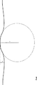
図は、本発明によって生成された断面変形を、概略的に非縮尺方式で示している。この断面変形の先端は「球面状」に形成されており、断面変形の高さ(h)よりも大きな先端半径(頂点半径)(r)を有している。図には塗装は示されていない。この図はレーザビームの処理領域を示すだけのものであり、この領域においては、塗装は、断面変形の生成中に既に気化してしまっているからである。 The figure schematically shows the cross-sectional deformation produced by the present invention in an unscaled manner. The tip of the cross-sectional deformation is formed in a “spherical shape”, and has a tip radius (vertex radius) (r) larger than the height (h) of the cross-sectional deformation. The painting is not shown in the figure. This figure only shows the processing area of the laser beam, in which the coating has already vaporized during the generation of the cross-sectional deformation.
第1の実施例においては、厚さ0.8mmの電気亜鉛めっき鋼板の金属板を処理した。走査装置をその上に均等に移動させて、レーザビームを順次複数の処理表面域に導く。走査装置は2次元の回動可能なコンピュータ制御のミラー装置から構成される。走査装置は金属板の表面から約320mmの位置に配置し、レーザの焦点を表面上約20mmに合わせた。走査装置は、レーザビームを、1.25m/minの処理速度で処理表面域に導く。実際の処理表面域に到達する直前の最後の数ミクロンの位置で、レーザの出力を、5msの時間以内に3.5kWの処理出力に増大する。その後、走査装置は、レーザビームを、断面変形を生成するために塗装金属板の表面上で円周を描くように動かす。この円周の直径は0.12mmであり、処理には24ms必要である。円周径路を描き終わると、走査装置は、レーザビームを、次の処理表面域に移動させる。実際の処理表面域から離脱すると、レーザの出力を、5msの時間以内に再度予備設定された値に低下させる。溶融物の相互作用領域内部におけるレーザビームの円周状の動きによって、すなわち、横方向及び縦方向の成分を有する動きによって、溶融物は、加熱によって誘起される混合に加えて、補足的に活性化されあるいはほとんど攪拌される。この結果得られる断面変形は、その先端がより一層「球面化」する、すなわち、断面変形の高さ(140μm)よりも大きな先端半径を有する形態を呈する。この形態は、レーザビームの焦点をずらすことによって得られるものである。焦点をずらすことによって、処理表面域が、より広い処理面積にわたって、より均等に加熱されるからである。これによって、結果的に、塗装がより均等に気化し、金属板の平坦な窪みの中になだらかな輪郭の山の頂点が形成されるという形の断面変形が得られる。所要数の断面変形を生成した後、第2の金属板を重ね合わせて、引き続いてこの2枚の金属板を一緒に押圧し、相互に溶接する。 In the first embodiment, a 0.8 mm thick electrogalvanized steel sheet was processed. The scanning device is moved evenly thereon to sequentially direct the laser beam to a plurality of processing surface areas. The scanning device comprises a two-dimensional rotatable computer-controlled mirror device. The scanning device was placed at a position about 320 mm from the surface of the metal plate, and the laser was focused at about 20 mm on the surface. The scanning device directs the laser beam to the processing surface area at a processing speed of 1.25 m / min. At the last few microns, just before reaching the actual processing surface area, the laser power is increased to a processing power of 3.5 kW within a time of 5 ms. The scanning device then moves the laser beam to draw a circle on the surface of the painted metal plate to produce a cross-sectional deformation. The diameter of this circumference is 0.12 mm, and processing requires 24 ms. When the circumferential path has been drawn, the scanning device moves the laser beam to the next processing surface area. When deviating from the actual processing surface area, the laser output is reduced again to a preset value within a time of 5 ms. Due to the circumferential movement of the laser beam within the melt interaction area, i.e. movement with transverse and longitudinal components, the melt is supplementarily activated in addition to heating-induced mixing. Or almost stirred. The resulting cross-sectional deformation takes the form that its tip becomes more “spherical”, ie has a tip radius greater than the height of the cross-section deformation (140 μm). This form is obtained by shifting the focus of the laser beam. This is because by shifting the focus, the processing surface area is heated more uniformly over a larger processing area. This results in a cross-sectional deformation in the form of a more uniform vaporization of the coating and the formation of a gently contoured peak in the flat depression of the metal plate. After generating the required number of cross-sectional deformations, the second metal plates are overlaid and subsequently the two metal plates are pressed together and welded together.
第2の実施例においては、同じ材料であるが厚さが1.2mmの金属板を用いた。この厚さの金属板の場合は、良好な溶接線を形成するのに、2枚の金属板間の間隙を0.3mmまでさらに広げることが許容された。この金属板は、溶接に続いて、陰極浸漬塗装処理を行うことが予定されているので、0.2mmの最少間隙が必要である。このような理由から、前記のレーザパラメータを若干変更した。すなわち、円周の直径を0.11mmとし、レーザビームの処理速度を0.7m/minとし、処理時間を36msに延長した。このパラメータによって、220μmの高さを有し、金属板上に200μm突出した断面変形を得ることができ、所要の間隙が設定された。 In the second embodiment, a metal plate made of the same material but having a thickness of 1.2 mm was used. In the case of this thickness metal plate, it was allowed to further widen the gap between the two metal plates to 0.3 mm in order to form a good weld line . Since this metal plate is scheduled to be subjected to cathodic dip coating processing following welding, a minimum gap of 0.2 mm is required. For these reasons, the laser parameters were slightly changed. That is, the circumference diameter was set to 0.11 mm, the processing speed of the laser beam was set to 0.7 m / min, and the processing time was extended to 36 ms. With this parameter, it was possible to obtain a sectional deformation having a height of 220 μm and protruding 200 μm on the metal plate, and a required gap was set.
第3の実施例においては、厚さ1.2mmの電気亜鉛めっき鋼板を2枚少し離して重ね合わせる形のものを提供する。レーザビームの出力を3.5kW、処理速度を7m/minとし、レーザビームを、走査装置によって、処理表面域の中心の回りに周回しかつその中心に向かって狭まっていく螺旋を描くように動かす。螺旋の初期直径は1.2mmであり、レーザビームは5回の回転後にその中心に達する。これに要した処理時間は100msであった。外側から内側に向かう螺旋形状の動きによって、さらに一層なだらかな断面変形が、金属板のレーザと反対側の表面上になだらかな輪郭の山の頂点の形で形成された。所要数の断面変形を生成した後、2枚の金属板を一緒に押圧して相互に溶接した。この場合、溶接線は少なくともいくつかの断面変形の上を通過させた。 In the third embodiment, there is provided a type in which two electrogalvanized steel sheets having a thickness of 1.2 mm are overlapped slightly apart. The laser beam output is 3.5 kW, the processing speed is 7 m / min, and the laser beam is moved by the scanning device so as to draw a spiral that circulates around the center of the processing surface area and narrows toward the center. . The initial diameter of the helix is 1.2 mm and the laser beam reaches its center after 5 revolutions. The processing time required for this was 100 ms. With a spiral-shaped movement from the outside to the inside, an even gentler cross-sectional deformation was formed in the form of a gently contoured peak on the surface of the metal plate opposite the laser. After generating the required number of cross-sectional deformations, the two metal plates were pressed together and welded together. In this case, the weld line was passed over at least some cross-sectional deformations.
1.5mm厚さの金属板の場合は、より大きな螺旋半径1.6mmが必要であり、中心への径路については7回転が必要である。これによって、処理時間は、金属板のレーザとは反対側の面の断面変形1個当たり160msに増大した。 In the case of a metal plate with a thickness of 1.5 mm, a larger spiral radius of 1.6 mm is required, and the path to the center requires 7 rotations. This increased the processing time to 160 ms per cross-sectional deformation on the surface of the metal plate opposite to the laser.
第5の実施例においては、厚さ1.0mmの電気亜鉛めっきしたTRIP700鋼の金属板を用い、走査装置をその上で均等に動かし、走査装置がレーザビームを順次複数の処理表面域に移動させた。走査装置は、金属板の表面から約300mm離した位置に置き、レーザの焦点は表面に合わせた。走査装置は、レーザビームを処理表面域に8m/minの処理速度で導く。実際の処理表面域に到達する直前の最後の数ミクロンの位置で、レーザの出力を、5msの時間以内に、1.9kWの基礎出力から2.2kWの処理出力に増大する。続いて、走査装置は、レーザビームを、断面変形生成のために塗装金属板の表面上で円周状に動かす。円周の直径は1.8mmである。この処理には70msを要した。円周径路の走査実行後、走査装置はレーザビームを次の処理表面域に移す。実際の処理表面域から離脱すると、レーザの出力を、5msの時間以内に上記の値に低減する。溶融物の相互作用領域内部におけるレーザビームの円周状の動きによって、すなわち、横方向及び縦方向の成分を有する動きによって、溶融物は、加熱によって誘起される混合に加えて、補足的に活性化されあるいはほとんど攪拌される。この結果、TRIP700高張力鋼の金属板の場合には、クレータ形状の断面変形が形成され、その「球面状の」壁面がスペーサとして機能する。所要数の断面変形を生成した後、第2のTRIP鋼金属板を重ね合わせて、引き続いてこの2枚の金属板を一緒に押圧し、相互に溶接する。 In the fifth embodiment, a 1.0 mm thick electrogalvanized TRIP700 steel metal plate is used, the scanning device is moved evenly over it, and the scanning device sequentially moves the laser beam to a plurality of processing surface areas. I let you. The scanning device was placed at a position approximately 300 mm away from the surface of the metal plate, and the laser was focused on the surface. The scanning device guides the laser beam to the processing surface area at a processing speed of 8 m / min. At the last few microns, just before reaching the actual processing surface area, the laser power is increased from a basic power of 1.9 kW to a processing power of 2.2 kW within a time of 5 ms. Subsequently, the scanning device moves the laser beam circumferentially on the surface of the painted metal plate to generate a cross-sectional deformation. The diameter of the circumference is 1.8 mm. This process took 70 ms. After performing a scan of the circumferential path, the scanning device moves the laser beam to the next processing surface area. When leaving the actual processing surface area, the output of the laser is reduced to the above value within 5 ms. Due to the circumferential movement of the laser beam within the melt interaction area, i.e. movement with transverse and longitudinal components, the melt is supplementarily active in addition to heating-induced mixing. Or almost stirred. As a result, in the case of a TRIP700 high-strength steel metal plate, a crater-shaped cross-sectional deformation is formed, and the “spherical” wall surface functions as a spacer. After generating the required number of cross-sectional deformations, a second TRIP steel metal plate is overlaid and the two metal plates are subsequently pressed together and welded together.
本発明による方法は、上記の実施例の実施形態において、自動車工業における塗装金属板のレーザ溶接、特に高張力鋼のレーザ溶接に特に適していることが明らかになった。特に、処理時間に関して大幅な利得を達成することができる。断面変形の形状が改善されることによって、かつ又、溶接線を断面変形の少なくとも一部分の上を通すことによって、防食性をも改善することができる。 It has been found that the method according to the invention is particularly suitable for laser welding of painted metal plates in the automotive industry, in particular laser welding of high-strength steel, in the embodiment of the above examples. In particular, significant gains in terms of processing time can be achieved. Corrosion protection can also be improved by improving the shape of the cross-sectional deformation and also by passing a weld line over at least a portion of the cross-sectional deformation.
本発明は、上記の実施例に限定されるわけではなく、さらに幅広く適用することができる。 The present invention is not limited to the above-described embodiments, and can be applied to a wider range.
従って、例えば、走査装置を、ミラー系によって構成する代わりに音響光学変調器によって構成することが考えられる。さらに、レーザ走査器を要素表面上に導く代わりに、定置式走査器の構成要素を動かすことも可能である。場合によっては、走査器と構成要素とに互いに協調した動きを行わせることができる。 Therefore, for example, it is conceivable that the scanning device is constituted by an acousto-optic modulator instead of a mirror system. Further, instead of directing the laser scanner onto the element surface, it is possible to move the stationary scanner components. In some cases, the scanner and components can be coordinated with each other.
さらに、走査装置の金属板までの距離、及び焦点をずらす程度、あるいは前記の動きのパターンは、決定的な重要因子ではなく、必要に応じて、例えば、レーザの出力、あるいは金属板及び/又は塗装の材料に適合させることができる。レーザの出力を、照射中補足的に適切な方法で変化させることも有利となる場合がある。 Furthermore, the distance to the metal plate of the scanning device and the degree of defocusing or the pattern of the movement is not a critical factor and can be determined, for example, by the laser output or the metal plate and / or Can be adapted to the paint material. It may also be advantageous to vary the power of the laser in a supplementary manner during irradiation.
Claims (10)
レーザビームを、塗装金属板の表面上で円周を描くように動かすことによって、前記少なくとも1つの断面変形を生成し、該断面変形はその頂部において球面形状をなし、該頂部の球面形状の半径が、断面変形の高さよりも大きな値を有するように生成し、該高さは、断面変形の底部部分における金属板の窪みの最深部から断面変形の端部までの距離として測定されることを特徴とするレーザ加工法。In a laser processing method of a painted metal sheet, wherein at least one cross-sectional deformation protruding from the surface is generated on a surface on at least one side of at least one painted metal sheet by means of a laser,
The at least one cross-sectional deformation is generated by moving the laser beam in a circle on the surface of the painted metal plate, the cross-sectional deformation having a spherical shape at the top, and the radius of the spherical shape at the top. but generated to have a value greater than the height of the cross-section variation, the height, the distance to the end of the deepest portion or al cross-section deformation of the recess of Rukin genus plate put in the bottom portion of the cross section variations A laser processing method characterized by being measured as follows.
該高さは、該断面変形の底部部分における該金属板の窪みの最深部から該断面変形の端部までの距離として測定されることを特徴とする塗装金属板。At least one cross-sectional deformation projecting from the surface, by a laser, at least one side coated metal plate which is produced on the surface of, and Ugokasuko as a laser beam, to draw a circle on the surface of the coated metal plate The cross-sectional deformation is generated in a spherical shape at the top, and the radius of the spherical shape of the top is generated to have a value larger than the height of the cross-sectional deformation ,
The height, painted metal plate, characterized in that it is measured as the distance from the deepest portion of the recess of the metal plate at the bottom portion of the cross section variations to the end of the cross section variations.
Applications Claiming Priority (2)
| Application Number | Priority Date | Filing Date | Title |
|---|---|---|---|
| DE102004005358A DE102004005358B4 (en) | 2004-02-03 | 2004-02-03 | Process for the laser processing of coated sheets and coated sheet metal |
| PCT/EP2005/000766 WO2005075141A1 (en) | 2004-02-03 | 2005-01-27 | Method for modifying the topography of coated sheet metal using a laser beam and coated sheet metal with a topographical modification of this type |
Publications (3)
| Publication Number | Publication Date |
|---|---|
| JP2007520357A JP2007520357A (en) | 2007-07-26 |
| JP2007520357A5 JP2007520357A5 (en) | 2010-07-15 |
| JP4645853B2 true JP4645853B2 (en) | 2011-03-09 |
Family
ID=34832503
Family Applications (1)
| Application Number | Title | Priority Date | Filing Date |
|---|---|---|---|
| JP2006551771A Active JP4645853B2 (en) | 2004-02-03 | 2005-01-27 | Method of deforming cross section of coated metal plate by laser beam and painted metal plate having this kind of cross section deformation |
Country Status (10)
| Country | Link |
|---|---|
| US (1) | US7939781B2 (en) |
| EP (1) | EP1711303B1 (en) |
| JP (1) | JP4645853B2 (en) |
| KR (1) | KR20060126789A (en) |
| CN (1) | CN1914000A (en) |
| AT (1) | ATE366163T1 (en) |
| BR (1) | BRPI0507398A (en) |
| DE (2) | DE102004005358B4 (en) |
| ES (1) | ES2287893T3 (en) |
| WO (1) | WO2005075141A1 (en) |
Families Citing this family (7)
| Publication number | Priority date | Publication date | Assignee | Title |
|---|---|---|---|---|
| JP2008068270A (en) * | 2006-09-12 | 2008-03-27 | Disco Abrasive Syst Ltd | Laser beam machine |
| DE102008021636B3 (en) * | 2008-04-30 | 2009-11-19 | Esk Ceramics Gmbh & Co. Kg | Method for fixing a connecting element on a workpiece and component of a workpiece with a connecting element fixed thereon |
| DE102008033113A1 (en) * | 2008-07-15 | 2010-01-21 | Bayerische Motoren Werke Aktiengesellschaft | Welding process to produce chassis component of motor vehicle, comprises providing first and second metal sheets to be welded together, fixing edge region of first metal sheet to second metal sheet, and scanning position of the edge region |
| US10155285B2 (en) | 2014-01-10 | 2018-12-18 | Panasonic Intellectual Property Management Co., Ltd. | Laser welding method and laser welding device |
| GB201502149D0 (en) * | 2015-02-09 | 2015-03-25 | Spi Lasers Uk Ltd | Apparatus and method for laser welding |
| JP6994324B2 (en) * | 2017-08-31 | 2022-01-14 | 株式会社神戸製鋼所 | Manufacture method and equipment for joints |
| DE102021215018A1 (en) | 2021-12-23 | 2023-06-29 | Fraunhofer-Gesellschaft zur Förderung der angewandten Forschung eingetragener Verein | Process for the production of three-dimensionally formed components that are formed with a metal sheet and at least one metal reinforcing element |
Citations (1)
| Publication number | Priority date | Publication date | Assignee | Title |
|---|---|---|---|---|
| JP2003311453A (en) * | 2002-04-23 | 2003-11-05 | Sumitomo Metal Ind Ltd | Laser welding method and welding set |
Family Cites Families (16)
| Publication number | Priority date | Publication date | Assignee | Title |
|---|---|---|---|---|
| FR2547756B1 (en) * | 1983-06-24 | 1986-06-06 | Sciaky Sa | LASER BEAM POINT WELDING PROCESS AND INSTALLATION |
| JPH01147967A (en) * | 1987-12-03 | 1989-06-09 | Mitsubishi Electric Corp | Vertical deflection linearity correction circuit |
| GB2236846B (en) * | 1988-11-22 | 1992-10-14 | Fiat Auto Spa | Laser welding monitoring systems. |
| US5236763A (en) | 1990-08-07 | 1993-08-17 | Praxair S. T. Technology, Inc. | Method for engraving solid articles with laser beams and the articles produced |
| JPH07155974A (en) | 1993-12-09 | 1995-06-20 | Horie Metal Co Ltd | Method for laser beam welding of plated steel sheet |
| DE4407190A1 (en) * | 1994-03-04 | 1995-09-07 | Thyssen Laser Technik Gmbh | Process for preparing the joining areas of coated workpieces for welding with laser radiation and lap joint for welding coated workpieces |
| US5595670A (en) * | 1995-04-17 | 1997-01-21 | The Twentyfirst Century Corporation | Method of high speed high power welding |
| US6048255A (en) | 1995-08-22 | 2000-04-11 | Seagate Technology, Inc. | Pulsed laser surface treatments for magnetic recording media |
| JPH1147967A (en) * | 1997-07-31 | 1999-02-23 | Nec Corp | Welding method |
| CA2209804A1 (en) * | 1997-08-15 | 1999-02-15 | Hongping Gu | Method of laser beam welding of zinc-coated steel sheet |
| DE19947719A1 (en) * | 1999-10-05 | 2001-04-12 | Daimler Chrysler Ag | Vehicle chassis or chassis component is made of a metallic material that hardens in specified temperature region |
| US6483069B2 (en) * | 2000-10-02 | 2002-11-19 | The Boeing Company | Joining of structural members by welding |
| GB0112234D0 (en) * | 2001-05-18 | 2001-07-11 | Welding Inst | Surface modification |
| US6740845B2 (en) * | 2002-05-24 | 2004-05-25 | Alcoa Inc. | Laser welding with beam oscillation |
| FR2840832B1 (en) | 2002-06-14 | 2004-07-23 | Air Liquide | USE OF HELIUM / NITROGEN GAS MIXTURES IN LASER WELDING OF REDUCED SIDINGS |
| DE10241593B4 (en) * | 2002-09-05 | 2005-03-03 | Daimlerchrysler Ag | Process for the laser processing of coated metal sheets |
-
2004
- 2004-02-03 DE DE102004005358A patent/DE102004005358B4/en not_active Expired - Lifetime
-
2005
- 2005-01-27 BR BRPI0507398-7A patent/BRPI0507398A/en not_active IP Right Cessation
- 2005-01-27 AT AT05701198T patent/ATE366163T1/en not_active IP Right Cessation
- 2005-01-27 ES ES05701198T patent/ES2287893T3/en active Active
- 2005-01-27 EP EP05701198A patent/EP1711303B1/en active Active
- 2005-01-27 CN CNA200580003839XA patent/CN1914000A/en active Pending
- 2005-01-27 JP JP2006551771A patent/JP4645853B2/en active Active
- 2005-01-27 WO PCT/EP2005/000766 patent/WO2005075141A1/en active IP Right Grant
- 2005-01-27 DE DE502005000977T patent/DE502005000977D1/en active Active
- 2005-01-27 KR KR1020067016987A patent/KR20060126789A/en not_active Application Discontinuation
- 2005-01-27 US US10/588,356 patent/US7939781B2/en active Active
Patent Citations (1)
| Publication number | Priority date | Publication date | Assignee | Title |
|---|---|---|---|---|
| JP2003311453A (en) * | 2002-04-23 | 2003-11-05 | Sumitomo Metal Ind Ltd | Laser welding method and welding set |
Also Published As
| Publication number | Publication date |
|---|---|
| DE502005000977D1 (en) | 2007-08-16 |
| KR20060126789A (en) | 2006-12-08 |
| US20070272665A1 (en) | 2007-11-29 |
| JP2007520357A (en) | 2007-07-26 |
| DE102004005358B4 (en) | 2007-03-22 |
| ATE366163T1 (en) | 2007-07-15 |
| ES2287893T3 (en) | 2007-12-16 |
| EP1711303A1 (en) | 2006-10-18 |
| BRPI0507398A (en) | 2007-07-10 |
| WO2005075141A1 (en) | 2005-08-18 |
| EP1711303B1 (en) | 2007-07-04 |
| DE102004005358A1 (en) | 2005-09-08 |
| CN1914000A (en) | 2007-02-14 |
| US7939781B2 (en) | 2011-05-10 |
Similar Documents
| Publication | Publication Date | Title |
|---|---|---|
| JP4645853B2 (en) | Method of deforming cross section of coated metal plate by laser beam and painted metal plate having this kind of cross section deformation | |
| CA2802611C (en) | Method of laser welding | |
| CN108778607B (en) | Laser welding steel with power modulation to avoid hot cracking | |
| WO2016189855A1 (en) | Laser welding method | |
| Ayoola et al. | Effect of beam shape and spatial energy distribution on weld bead geometry in conduction welding | |
| JP2012170989A (en) | Laser lap welding method | |
| JP2009148781A (en) | Laser welding method | |
| JP6299136B2 (en) | Laser welding method and laser welding apparatus for steel sheet | |
| JP2011230157A (en) | Laser lap welding method for galvanized steel sheet | |
| JPH0732180A (en) | Laser beam welding method for galvanized steel sheets | |
| JP4335819B2 (en) | Metal processing method | |
| JP6657558B2 (en) | Processed parts excellent in corrosion resistance and method of manufacturing the same | |
| US20230001513A1 (en) | Method for laser welding two coated workpieces | |
| JP6575604B2 (en) | Laser welding method and laser welding apparatus | |
| JP4210857B2 (en) | Laser machining method for plated plate | |
| JP2020050906A (en) | Heat treatment method and heat treatment apparatus for three-dimensional workpiece | |
| KR20180013481A (en) | Laser welding method | |
| US7144492B2 (en) | Assembly comprised of joined conductive components having cataphoretic paint layer and process for manufacture thereof | |
| CA3054472C (en) | Method for laser welding end faces | |
| US20210094124A1 (en) | Manufacturing method of component | |
| JP6947669B2 (en) | Laser welding method | |
| JP2018069258A (en) | Laser welding method and laser welding equipment | |
| CN118401331A (en) | Method for welding sheet material having a coating comprising an aluminium-silicon alloy | |
| JP2024041118A (en) | Laser welding apparatus and laser welding method | |
| JP2023176154A (en) | Laser welding method |
Legal Events
| Date | Code | Title | Description |
|---|---|---|---|
| RD04 | Notification of resignation of power of attorney |
Free format text: JAPANESE INTERMEDIATE CODE: A7424 Effective date: 20070720 |
|
| A131 | Notification of reasons for refusal |
Free format text: JAPANESE INTERMEDIATE CODE: A131 Effective date: 20090812 |
|
| A521 | Request for written amendment filed |
Free format text: JAPANESE INTERMEDIATE CODE: A523 Effective date: 20091112 |
|
| A131 | Notification of reasons for refusal |
Free format text: JAPANESE INTERMEDIATE CODE: A131 Effective date: 20100203 |
|
| A601 | Written request for extension of time |
Free format text: JAPANESE INTERMEDIATE CODE: A601 Effective date: 20100421 |
|
| A602 | Written permission of extension of time |
Free format text: JAPANESE INTERMEDIATE CODE: A602 Effective date: 20100428 |
|
| A524 | Written submission of copy of amendment under article 19 pct |
Free format text: JAPANESE INTERMEDIATE CODE: A524 Effective date: 20100525 |
|
| TRDD | Decision of grant or rejection written | ||
| A01 | Written decision to grant a patent or to grant a registration (utility model) |
Free format text: JAPANESE INTERMEDIATE CODE: A01 Effective date: 20101110 |
|
| A01 | Written decision to grant a patent or to grant a registration (utility model) |
Free format text: JAPANESE INTERMEDIATE CODE: A01 |
|
| A61 | First payment of annual fees (during grant procedure) |
Free format text: JAPANESE INTERMEDIATE CODE: A61 Effective date: 20101123 |
|
| FPAY | Renewal fee payment (event date is renewal date of database) |
Free format text: PAYMENT UNTIL: 20131217 Year of fee payment: 3 |
|
| R150 | Certificate of patent or registration of utility model |
Ref document number: 4645853 Country of ref document: JP Free format text: JAPANESE INTERMEDIATE CODE: R150 |
|
| R250 | Receipt of annual fees |
Free format text: JAPANESE INTERMEDIATE CODE: R250 |
|
| R250 | Receipt of annual fees |
Free format text: JAPANESE INTERMEDIATE CODE: R250 |
|
| R250 | Receipt of annual fees |
Free format text: JAPANESE INTERMEDIATE CODE: R250 |
|
| R250 | Receipt of annual fees |
Free format text: JAPANESE INTERMEDIATE CODE: R250 |
|
| R250 | Receipt of annual fees |
Free format text: JAPANESE INTERMEDIATE CODE: R250 |
|
| R250 | Receipt of annual fees |
Free format text: JAPANESE INTERMEDIATE CODE: R250 |
|
| R250 | Receipt of annual fees |
Free format text: JAPANESE INTERMEDIATE CODE: R250 |
|
| R250 | Receipt of annual fees |
Free format text: JAPANESE INTERMEDIATE CODE: R250 |
|
| R250 | Receipt of annual fees |
Free format text: JAPANESE INTERMEDIATE CODE: R250 |
|
| R250 | Receipt of annual fees |
Free format text: JAPANESE INTERMEDIATE CODE: R250 |
|
| R250 | Receipt of annual fees |
Free format text: JAPANESE INTERMEDIATE CODE: R250 |