WO2016189855A1 - Laser welding method - Google Patents
Laser welding method Download PDFInfo
- Publication number
- WO2016189855A1 WO2016189855A1 PCT/JP2016/002503 JP2016002503W WO2016189855A1 WO 2016189855 A1 WO2016189855 A1 WO 2016189855A1 JP 2016002503 W JP2016002503 W JP 2016002503W WO 2016189855 A1 WO2016189855 A1 WO 2016189855A1
- Authority
- WO
- WIPO (PCT)
- Prior art keywords
- protrusion
- laser
- welding
- steel plate
- plate
- Prior art date
Links
Images


Classifications
-
- B—PERFORMING OPERATIONS; TRANSPORTING
- B23—MACHINE TOOLS; METAL-WORKING NOT OTHERWISE PROVIDED FOR
- B23K—SOLDERING OR UNSOLDERING; WELDING; CLADDING OR PLATING BY SOLDERING OR WELDING; CUTTING BY APPLYING HEAT LOCALLY, e.g. FLAME CUTTING; WORKING BY LASER BEAM
- B23K26/00—Working by laser beam, e.g. welding, cutting or boring
- B23K26/50—Working by transmitting the laser beam through or within the workpiece
- B23K26/57—Working by transmitting the laser beam through or within the workpiece the laser beam entering a face of the workpiece from which it is transmitted through the workpiece material to work on a different workpiece face, e.g. for effecting removal, fusion splicing, modifying or reforming
-
- B—PERFORMING OPERATIONS; TRANSPORTING
- B23—MACHINE TOOLS; METAL-WORKING NOT OTHERWISE PROVIDED FOR
- B23K—SOLDERING OR UNSOLDERING; WELDING; CLADDING OR PLATING BY SOLDERING OR WELDING; CUTTING BY APPLYING HEAT LOCALLY, e.g. FLAME CUTTING; WORKING BY LASER BEAM
- B23K26/00—Working by laser beam, e.g. welding, cutting or boring
- B23K26/08—Devices involving relative movement between laser beam and workpiece
- B23K26/082—Scanning systems, i.e. devices involving movement of the laser beam relative to the laser head
-
- B—PERFORMING OPERATIONS; TRANSPORTING
- B23—MACHINE TOOLS; METAL-WORKING NOT OTHERWISE PROVIDED FOR
- B23K—SOLDERING OR UNSOLDERING; WELDING; CLADDING OR PLATING BY SOLDERING OR WELDING; CUTTING BY APPLYING HEAT LOCALLY, e.g. FLAME CUTTING; WORKING BY LASER BEAM
- B23K26/00—Working by laser beam, e.g. welding, cutting or boring
- B23K26/08—Devices involving relative movement between laser beam and workpiece
- B23K26/0869—Devices involving movement of the laser head in at least one axial direction
- B23K26/0876—Devices involving movement of the laser head in at least one axial direction in at least two axial directions
- B23K26/0884—Devices involving movement of the laser head in at least one axial direction in at least two axial directions in at least in three axial directions, e.g. manipulators, robots
-
- B—PERFORMING OPERATIONS; TRANSPORTING
- B23—MACHINE TOOLS; METAL-WORKING NOT OTHERWISE PROVIDED FOR
- B23K—SOLDERING OR UNSOLDERING; WELDING; CLADDING OR PLATING BY SOLDERING OR WELDING; CUTTING BY APPLYING HEAT LOCALLY, e.g. FLAME CUTTING; WORKING BY LASER BEAM
- B23K26/00—Working by laser beam, e.g. welding, cutting or boring
- B23K26/20—Bonding
- B23K26/21—Bonding by welding
- B23K26/22—Spot welding
-
- B—PERFORMING OPERATIONS; TRANSPORTING
- B23—MACHINE TOOLS; METAL-WORKING NOT OTHERWISE PROVIDED FOR
- B23K—SOLDERING OR UNSOLDERING; WELDING; CLADDING OR PLATING BY SOLDERING OR WELDING; CUTTING BY APPLYING HEAT LOCALLY, e.g. FLAME CUTTING; WORKING BY LASER BEAM
- B23K26/00—Working by laser beam, e.g. welding, cutting or boring
- B23K26/20—Bonding
- B23K26/21—Bonding by welding
- B23K26/24—Seam welding
- B23K26/244—Overlap seam welding
-
- B—PERFORMING OPERATIONS; TRANSPORTING
- B23—MACHINE TOOLS; METAL-WORKING NOT OTHERWISE PROVIDED FOR
- B23K—SOLDERING OR UNSOLDERING; WELDING; CLADDING OR PLATING BY SOLDERING OR WELDING; CUTTING BY APPLYING HEAT LOCALLY, e.g. FLAME CUTTING; WORKING BY LASER BEAM
- B23K26/00—Working by laser beam, e.g. welding, cutting or boring
- B23K26/20—Bonding
- B23K26/32—Bonding taking account of the properties of the material involved
- B23K26/322—Bonding taking account of the properties of the material involved involving coated metal parts
-
- B—PERFORMING OPERATIONS; TRANSPORTING
- B23—MACHINE TOOLS; METAL-WORKING NOT OTHERWISE PROVIDED FOR
- B23K—SOLDERING OR UNSOLDERING; WELDING; CLADDING OR PLATING BY SOLDERING OR WELDING; CUTTING BY APPLYING HEAT LOCALLY, e.g. FLAME CUTTING; WORKING BY LASER BEAM
- B23K2101/00—Articles made by soldering, welding or cutting
- B23K2101/006—Vehicles
-
- B—PERFORMING OPERATIONS; TRANSPORTING
- B23—MACHINE TOOLS; METAL-WORKING NOT OTHERWISE PROVIDED FOR
- B23K—SOLDERING OR UNSOLDERING; WELDING; CLADDING OR PLATING BY SOLDERING OR WELDING; CUTTING BY APPLYING HEAT LOCALLY, e.g. FLAME CUTTING; WORKING BY LASER BEAM
- B23K2101/00—Articles made by soldering, welding or cutting
- B23K2101/18—Sheet panels
-
- B—PERFORMING OPERATIONS; TRANSPORTING
- B23—MACHINE TOOLS; METAL-WORKING NOT OTHERWISE PROVIDED FOR
- B23K—SOLDERING OR UNSOLDERING; WELDING; CLADDING OR PLATING BY SOLDERING OR WELDING; CUTTING BY APPLYING HEAT LOCALLY, e.g. FLAME CUTTING; WORKING BY LASER BEAM
- B23K2101/00—Articles made by soldering, welding or cutting
- B23K2101/34—Coated articles, e.g. plated or painted; Surface treated articles
-
- B—PERFORMING OPERATIONS; TRANSPORTING
- B23—MACHINE TOOLS; METAL-WORKING NOT OTHERWISE PROVIDED FOR
- B23K—SOLDERING OR UNSOLDERING; WELDING; CLADDING OR PLATING BY SOLDERING OR WELDING; CUTTING BY APPLYING HEAT LOCALLY, e.g. FLAME CUTTING; WORKING BY LASER BEAM
- B23K2103/00—Materials to be soldered, welded or cut
- B23K2103/02—Iron or ferrous alloys
- B23K2103/04—Steel or steel alloys
Definitions
- the present disclosure relates to a laser welding control method that is effective in reducing blowholes and pits in laser welding of an object to be welded which is a surface-treated member such as a galvanized steel sheet.
- Galvanized steel sheet is excellent in rust prevention and corrosion resistance. Therefore, in recent years, galvanized steel sheets have been used for automobile parts, building steel members, and the like, and the demand has been increasing year by year.
- Patent Document 1 a method is disclosed in which a minute gap is formed between two stacked metal plating plates to release plating metal gas (for example, Patent Document 1).
- Patent Document 2 a method is disclosed in which a minute gap is formed between two stacked metal plating plates to release plating metal gas (for example, Patent Document 1).
- Patent Document 1 will be described with reference to FIG.
- the two plated steel sheets (the plated steel sheet 110 and the plated steel sheet 120) that are superposed are arranged so that the protruding portions 114 of the plated steel sheet 110 are in line contact with the surface of the plated steel sheet 120.
- a gap H (0.1 mm or more) is formed between the plated steel plate 110 and the plated steel plate 120 by the protrusion 114. At this time, the gap H is equal to the height h of the protrusion 114.
- the plated steel plate 110 is irradiated with a laser beam LA.
- the laser beam LA is irradiated along the groove 116 from the groove 116 side opposite to the top 115 of the protrusion 114, and the plated steel sheet 110 is seam welded.
- the laser beam LA output from the laser generator (not shown) is focused through the lens 132 held by the lens holder 131 and has a high energy density.
- the plated steel sheet 110 is irradiated as a minute spot. First, the irradiation local part of the plated steel sheet 110 is melted, and then the irradiation local part of the second plated steel sheet 120 is melted.
- a region indicated by a two-dot chain line in FIG. 8 is a molten pool MP.
- the plating layer 112, the plating layer 113, the plating layer 122, and the plating layer 123 are also melted and the metal vapor GS is generated, but the metal vapor GS generated at the joint between the plated steel plate 110 and the plated steel plate 120 is the gap H. Is released into the atmosphere via Therefore, bubbles do not remain in the molten pool MP. The surface of the molten pool MP of the plated steel plate 110 is not disturbed, becomes a smooth surface, and does not cause an undercut.
- the plated steel sheet 210 has a protrusion 230 and a protrusion 231. Then, after overlapping the plated steel plate 210 and the plated steel plate 220, the region R between the protruding portion 230 and the protruding portion 231 is irradiated with a laser beam 250 output from a laser generator (not shown). Welding is done. A gap H is formed between the plated steel sheet 210 and the plated steel sheet 220 by the protrusion 230 and the protrusion 231. The gap H is equal to the height h of the protrusion.
- the laser beam 250 is applied to the region R between the protruding portion 230 and the protruding portion 231 of the plated steel sheet 210.
- the laser beam 250 is irradiated as a minute spot out of focus through a lens 252 held by the beam irradiation nozzle 251.
- the irradiation position of the laser beam 250 is usually performed at an intermediate point between the protrusion 230 and the protrusion 231, but the region R between the protrusion 230 and the protrusion 231 excluding the protrusion 230 and the protrusion 231. If it is within, it may be shifted from the middle point.
- the irradiated portion of the plated steel plate 210 and the irradiated portion of the plated steel plate 220 are sequentially melted to form a molten pool 260.
- the plating layers 212a, 212b, 222a, and 222b are also melted to generate metal vapor.
- the metal vapor generated from the plating layers 212a and 222a is released into the atmosphere through the gap S formed between the plated steel plate 210 and the plated steel plate 220. Therefore, bubbles do not remain in the molten pool 260.
- the weld pool 260 has a smooth surface without any blowholes when welding is completed, and the welding strength is constant.
- JP 7-155974 A Japanese Patent Laid-Open No. 10-216974
- the first steel plate and the second steel plate are in contact with each other so that the first steel plate has a protrusion and the tip of the protrusion formed on the first steel plate is in contact with the second steel plate.
- the figure which shows the spiral laser irradiation in Embodiment 1 of this indication The figure which shows the relationship between the diameter of the protrusion part in the spiral irradiation pattern in Embodiment 1 of this indication, and a spiral diameter Partial view of another protrusion in the first embodiment of the present disclosure
- H for example, H between the plated steel plate 110 and the plated steel plate 120.
- the groove 116 of the plated steel plate 110 is irradiated with the laser beam LA, and the plated steel plate 110 and the plated steel plate 120 are seam welded.
- a portion having a gap between the plated steel plate 110 and the plated steel plate 120 may be laser welded.
- protrusion part other than the protrusion part 114 exists in the plated steel plate 110
- protrusion parts other than the protrusion part 114 and the plated steel plate 120 contact, and the protrusion part 114 and the plated steel plate 120 contact.
- the gap between the protruding portion 114 and the plated steel sheet 120 is large, there is a possibility of leading to poor welding such as perforation.
- the laser is applied to the region R between the protruding portion 230 and the protruding portion 231 of the plated steel plate 210. Welding is performed by irradiating the beam 250.
- the laser beam 250 is output from a laser generator (not shown).
- both the protrusion 230 and the protrusion 231 are not necessarily in contact with the plated steel plate 220 due to the accuracy of work set and jig fixing.
- one projecting portion here, projecting portion 230
- the gap H equal to or higher than the height h (0.1 mm in the present embodiment) of the projecting portion 230 is a plated steel plate.
- the gap H between the plated steel sheet 210 and the plated steel sheet 220 becomes larger than the height h of the protrusion 230, which may lead to poor welding such as perforation.
- FIG. 1 is a diagram showing a schematic configuration of a laser welding apparatus.
- FIG. 2A is a diagram showing spiral laser irradiation.
- FIG. 2B is a diagram illustrating a relationship between the diameter a of the protrusion 12 and the spiral diameter b in the spiral irradiation pattern.
- FIG. 2C is a partial view of another protrusion.
- FIG. 3 is a diagram illustrating an example of a tolerance for the diameter a of the protrusion 12.
- FIG. 4A is a diagram showing spiral laser irradiation.
- FIG. 1 is a diagram showing a schematic configuration of a laser welding apparatus.
- FIG. 2A is a diagram showing spiral laser irradiation.
- FIG. 2B is a diagram illustrating a relationship between the diameter a of the protrusion 12 and the spiral diameter b in the spiral irradiation pattern.
- FIG. 2C is a partial view of another protrusion.
- FIG. 3 is a diagram illustrating
- FIG. 4B is a diagram illustrating a relationship between the width c of the protrusion 12 and the spiral width d in the spiral irradiation pattern.
- FIG. 5 is a diagram illustrating an example of a tolerance for the width c of the protrusion 12.
- FIG. 6 is a diagram illustrating an example of a tolerance for a gap
- FIG. 7 is a diagram illustrating an example of a tolerance for a positional deviation.
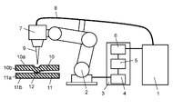
- the laser welding apparatus shown in FIG. 1 is an apparatus that performs laser welding. It is an apparatus that joins by irradiating a metal with laser light condensed as a heat source and locally melting and solidifying the metal.
- a case where laser welding of a galvanized steel sheet is performed using a laser welding apparatus will be described as an example.
- a laser welding apparatus shown in FIG. 1 includes a laser oscillator 1, a robot 2, a laser irradiation head 7 for irradiating laser light 9 to an upper plate 10 and a lower plate 11 that are workpieces, a laser oscillator 1, A robot controller 3 that controls the robot 2, the laser irradiation head 7, and the like, and a transmission fiber 8 that transmits laser light 9 from the laser oscillator 1 to the laser irradiation head 7 are provided.
- Laser light 9 having a beam diameter depending on the laser oscillator 1 and the transmission fiber 8 is transmitted to the laser irradiation head 7.
- the laser irradiation head 7 is attached to the robot 2.
- the robot controller 3 has a welding condition setting control unit 4, an operation control unit 5, and a laser output control unit 6.
- the welding condition setting control unit 4 performs setting of laser welding conditions, commands to other components, and the like.
- the operation control unit 5 controls the operation of the robot 2 or the laser irradiation head 7 based on the welding conditions set by the welding condition setting control unit 4 or the operation program taught in advance.
- the laser output control unit 6 controls the laser oscillator 1 to control the laser output based on the welding conditions set by the welding condition setting control unit 4.
- This laser welding apparatus oscillates laser light 9 from the laser oscillator 1 and focuses the laser light 9 oscillated from the laser oscillator 1 by a condenser lens (not shown) in the laser irradiation head 7. Then, the laser beam 9 focused by the condensing lens is irradiated from the overlapping direction (from the upper side in FIG. 2A) to the upper plate 10 and the lower plate 11 which are the objects to be welded, and the upper plate 10 and the lower plate 11 is welded.
- both the upper plate 10 and the lower plate 11 are galvanized steel plates. Note that the upper plate 10 and the lower plate 11 are not necessarily galvanized steel plates.
- the upper plate 10 and the lower plate 11 are overlaid. Then, the irradiation of the laser beam 9 is started from the center position of the protruding portion 12 provided in advance on the upper plate 10. The laser beam 9 is irradiated from the center of the protrusion 12 according to the spiral irradiation pattern 9a. When the laser beam 9 reaches the outer peripheral portion of the spiral irradiation pattern 9a, the laser irradiation is finished.
- the output of the laser beam 9 is an energy density capable of penetrating the upper plate 10 and the lower plate 11 which are galvanized steel plates.
- the energy density and the laser output vary depending on the plate thicknesses of the upper plate 10 and the lower plate 11, and the higher the plate thickness, the higher the energy density is required, and the higher the output of the laser light 9 is set.
- the upper plate 10 has a galvanized layer 10a and a galvanized layer 10b
- the lower plate 11 has a galvanized layer 11a and a galvanized layer 11b.
- the discharge path of the zinc vapor 13 can be created from the overlapping surface of the upper plate 10 and the lower plate 11 which are galvanized steel plates by welding spirally.
- the circular shape includes a circular shape and an oval shape.
- FIG. 2B shows the positional relationship when the protruding portion 12 is in contact with the lower plate 11
- FIG. 2C shows the positional relationship when the protruding portion 12 is not in contact with the lower plate 11. Note that FIG. 2C shows only the portion corresponding to the region surrounded by the broken line in FIG. 2B, and the other components are not shown.
- the height of the protruding portion 12 (hereinafter referred to as “height h”) is opposed to the lower plate 11 of the upper plate 10.
- the length between the surface to be faced and the surface facing the upper plate 10 of the lower plate 11 (hereinafter referred to as “clearance H”) is equal.
- FIG. 3 is an example, and the present disclosure is not limited to this.
- the conditions for the construction evaluation shown in FIG. 3 are as follows. As the upper plate 10 and the lower plate 11, galvanized steel plates having a coating film density of 45 g / m 2 and a plate thickness of 0.8 mm were used. The gap h ′ was set to 0 mm, and the height h of the protrusion 12 was set to 0.1 mm. The welding conditions were an output of 2.5 kW and a speed of 6 m / min. The horizontal axis is the length of the diameter a of the protrusion 12 of the upper plate 10, and the vertical axis is the spiral diameter b of the irradiation pattern 9a.
- the appropriate range in which the welding results are good is known.
- the result of the welding condition is represented by ⁇ and ⁇ .
- Visual confirmation was carried out ⁇ indicates a case where the bead appearance is good, and ⁇ indicates a case where pores remain.
- the spiral diameter b is 1.0 mm or more
- the spiral diameter b is 3.0 mm or more.
- the contact area between the upper plate 10 and the lower plate 11 increases. Due to the increase in the contact area, the effect of providing the protrusion 12 is lost. As a result, it becomes difficult to discharge the zinc vapor 13, and blow holes and pits remain in the weld bead and on the weld bead surface.
- the irradiation pattern 9b moves relatively with respect to a welding target object along the locus
- the irradiation pattern 9a is spiral
- the protruding portion 12 has a circular shape
- the protruding portion 12 has a line shape.
- both the upper plate 10 and the lower plate 11 are formed of a galvanized steel plate. Note that the upper plate 10 and the lower plate 11 are not necessarily galvanized steel plates.
- the upper plate 10 and the lower plate 11 are overlaid. Then, the irradiation of the laser beam 9 is started from the center position of the protrusion 12 provided in advance on the upper plate 10. The laser beam 9 is irradiated from the center position of the protrusion 12 according to the spiral irradiation pattern 9b. Welding is performed by laser irradiation with a spiral width d larger than the width c of the protrusion 12 with the center position of the protrusion 12 as a reference.
- the output of the laser beam 9 is an energy density that can penetrate the upper plate 10 and the lower plate 11 that are galvanized steel plates.
- the energy density and the laser output vary depending on the plate thicknesses of the upper plate 10 and the lower plate 11, and the higher the plate thickness, the higher the energy density is required, and the higher the output of the laser light 9 is set.
- the upper plate 10 has a galvanized layer 10a and a galvanized layer 10b
- the lower plate 11 has a galvanized layer 11a and a galvanized layer 11b. Then, by irradiating the laser beam 9 and welding the upper plate 10 and the lower plate 11, zinc vapor 13 is generated from the gap H, and welding can be performed without being affected by the zinc vapor.
- the width is larger than the width of the protruding portion 12 from the center position of the line-shaped protruding portion 12 provided in advance on the upper plate 10 that is a galvanized steel plate.
- a discharge path of the zinc vapor 13 can be created from the overlapping surface of the upper plate 10 and the lower plate 11 which are galvanized steel plates by welding with laser irradiation in a spiral shape with an irradiation pattern having a spiral width.
- FIG. 5 is an example, and the present disclosure is not limited to this.
- the upper plate 10 and the lower plate 11 galvanized steel plates having a coating film density of 45 g / m 2 and a plate thickness of 0.8 mm were used.
- the gap h ′ was set to 0 mm, and the height h of the protrusion 12 was set to 0.1 mm.
- the welding conditions were an output of 2.5 kW and a speed of 2 m / min.
- the horizontal axis is the length of the width c of the protrusion 12 of the upper plate 10, and the vertical axis is the spiral width d of the irradiation pattern 9b.
- the appropriate range in which the welding result is good is known.
- the result of the welding condition is represented by ⁇ and ⁇ .
- Visual confirmation was carried out ⁇ indicates a case where the bead appearance is good, and ⁇ indicates a case where pores remain.
- the spiral width d may be larger than the width c of the protrusion 12 by 0.5 mm or more.
- the spiral width d is 1.0 mm or more, and if the width c is 2.0 mm, the spiral width d is 2.5 mm or more.
- the contact area between the protrusion 12 provided on the upper plate 10 that is a galvanized steel sheet and the lower plate 11 increases. Due to this increase in the contact area, the effect of providing the protruding portion 12 is lost, and the discharge of the zinc vapor 13 becomes difficult, and blow holes and pits remain in the weld bead and on the weld bead surface.
- FIG. 6 shows an evaluation of the construction tolerance with respect to the clearance, in which the horizontal axis indicates the welding method (Comparison between Patent Documents 1 and 2 and this disclosure), the vertical axis indicates the clearance h ′, and the construction evaluation is performed. It is a result.
- a plate thickness of 0.8 mm of a galvanized steel sheet having a coating film density of 45 g / m 2 was used as the upper plate and the lower plate.
- the height h of the protruding portion was 0.1 mm, and the width of the protruding portion was 0.5 mm.
- FIG. 6 shows an appropriate range in which the welding result is good.
- the limit of the gap h ′ between the tip of the protrusion 230 (or the tip of the protrusion 231) and the plated steel plate 220 is limited to 0.2 mm. This is because, as in Patent Document 1, line welding in which laser irradiation is performed in a line shape has a narrow bead width, and the amount of molten metal necessary for the gap h 'exceeding the limit value cannot be secured. Note that FIG. 9 does not show a configuration having a gap h ′.
- the clearance rate by overlapping the upper plate 10 with a plate thickness of 0.8 mm and the lower plate 11 with a plate thickness of 0.8 mm is such that the laser is irradiated in a line shape as in Patent Document 1 and Patent Document 2.
- line welding which is equivalent to about 1/3 of the plate thickness
- in the welding of the line in which the laser is irradiated in a spiral shape of the present disclosure it is equivalent to about 2/3 of the plate thickness, and the tolerance is about 1.7 times.
- FIG. 7 shows an evaluation of the construction tolerance with respect to the positional deviation, in which the horizontal axis indicates the welding method (Comparison between Patent Documents 1 and 2 and the present disclosure), the vertical axis indicates the positional deviation, and the construction evaluation is performed. It is a result.
- a plate thickness of 0.8 mm of a galvanized steel plate having a coating film density of 45 g / m 2 was used as the upper plate and the lower plate.
- the height h of the protrusion is 0.1 mm, and the width of the protrusion is 0.5 mm.
- FIG. 7 shows an appropriate range in which the welding result is good.
- Patent Document 2 shown in FIG. 9 since the welding method involves laser irradiation between the protruding portion 230 and the protruding portion 231 in which a certain gap H is formed, the welding point is between the protruding portion 230 and the protruding portion 231. If the gap in the plate thickness direction is within a certain gap H region, welding can be performed without any problem.
- the positional deviation tolerance varies depending on the helical width d.
- a good bead appearance can be obtained if the spiral width d is set larger by 0.5 mm or more than the width c of the protrusion 12. That is, if the spiral width d is increased, the positional deviation tolerance becomes wider. As shown in FIG.
- the positional deviation is ⁇ 1 mm from the center of the protrusion
- the positional deviation is ⁇ 2 mm from the center of the protrusion when the spiral width d is 3 mm
- the positional deviation when the spiral width d is 4 mm.
- the upper plate 10 has the protruding portion 12 so that the tip of the protruding portion 12 formed on the upper plate 10 is in contact with the lower plate 11.
- the upper plate 10 and the lower plate 11 are overlapped.
- laser irradiation is performed spirally with an irradiation pattern 9b having a size larger than the protrusion 12, and at least one of the welding objects (upper plate 10 and lower plate 11) made of a plated steel plate is overlapped and welded. .
- the margin of positional deviation. Can be secured. Furthermore, the tolerance of the gap h ′ between the protruding portion 12 and the plated steel plate (lower plate 11) facing the protruding portion 12 can be improved. That is, it is possible to improve the tolerance of construction in both the gap h ′ between the protruding portion 12 and the corresponding plated steel plate (lower plate 11) and the positional deviation according to the size of the spiral width.
- a spiral or spiral pattern is formed on the protrusion 12 with an irradiation pattern having a predetermined size larger than the protrusion.
- this indication can acquire the same effect not only about the spiral irradiation pattern 9b but the spiral irradiation pattern 9a mentioned above.
- the upper plate 10 has the protruding portion 12, and the upper plate 10 is in contact with the tip of the protruding portion 12 formed on the upper plate 10 and the lower plate 11. 10 and the lower plate 11 are superposed on each other. Furthermore, in the laser welding method of the present disclosure, after the first step, the laser beam is irradiated toward the protruding portion 12 with the irradiation pattern 9a (or 9b) having a size larger than the size of the protruding portion 12 in plan view. It has two steps. Then, at least one surface of the surface facing the lower plate 11 of the upper plate 10 or the surface facing the upper plate 10 of the lower plate 11 is plated.
- the zinc vapor of galvanization can be smoothly discharged, and good welding can be performed without being affected by the zinc vapor.
- the pores generated in the weld bead or the weld bead surface can be suppressed, and the weldability can be improved.
- any surface-treated steel sheet can be used as long as it is a steel sheet on which metal plating having a boiling point lower than that of the steel sheet is applied.
- irradiation with a size larger than the protruding portion 12 is provided on the protruding portion 12 provided on the upper plate 10 or the lower plate 11.
- steam such as zinc-plated zinc steam
- the laser welding control method and the laser welding apparatus for welding the surface-treated member are industrially used. Useful.
Abstract
Disclosed is a laser welding controlling method which comprises: a first step wherein a first steel plate (10) having a protruding portion (12) and a second steel plate (11) are overlapped with each other so that the front end of the protruding portion (12) of the first steel plate (10) is in contact with the second steel plate (11); and a second step wherein laser light (9) is radiated toward the protruding portion (12) after the first step in radiation patterns (9a, 9b) that are larger in size than the size of the protruding portion (12) when viewed in plan. In this connection, a surface (10b) of the first steel plate (10) facing the second steel plate (11) and/or a surface (11a) of the second steel plate (11) facing the first steel plate (10) is subjected to plating.
Description
本開示は、亜鉛メッキ鋼板等の表面処理が行われた部材である溶接対象物のレーザ溶接において、ブローホールの低減やピットの低減に効果を発揮するレーザ溶接制御方法に関する。
The present disclosure relates to a laser welding control method that is effective in reducing blowholes and pits in laser welding of an object to be welded which is a surface-treated member such as a galvanized steel sheet.
亜鉛メッキ鋼板は、防錆や防食性に優れている。そのため、近年、亜鉛メッキ鋼板は、自動車部品や建築用鉄骨部材等に用いられ、年々その需要が高まっている。
Galvanized steel sheet is excellent in rust prevention and corrosion resistance. Therefore, in recent years, galvanized steel sheets have been used for automobile parts, building steel members, and the like, and the demand has been increasing year by year.
しかしながら、亜鉛メッキ鋼板を使用する際、課題がある。亜鉛メッキ鋼板の表面にメッキされている亜鉛は、鉄より融点が低い。そのため、亜鉛メッキ鋼板を溶接すると、その亜鉛が気化し、亜鉛蒸気が溶融池や溶融金属を通過して外部に拡散しようとする。しかし、レーザ溶接は、アーク溶接などに比べて溶接速度が速いため、溶融金属の凝固が速く、外部に亜鉛蒸気が完全に拡散できない。従って、溶接ビード内や溶接ビード表面にブローホールやピット(以下、気孔と呼ぶ)として、亜鉛蒸気が残存しやすい。このような気孔は、深刻な溶接欠陥につながる恐れもある。また、気孔が、爆飛現象により、穴あきやスパッタの発生につながることもある。
However, there are problems when using galvanized steel sheets. Zinc plated on the surface of a galvanized steel sheet has a lower melting point than iron. Therefore, when a galvanized steel sheet is welded, the zinc is vaporized, and zinc vapor passes through the molten pool and the molten metal and tends to diffuse outside. However, since laser welding has a higher welding speed than arc welding, the solidification of the molten metal is fast, and zinc vapor cannot be completely diffused outside. Accordingly, zinc vapor tends to remain as blow holes or pits (hereinafter referred to as pores) in the weld bead or on the weld bead surface. Such pores can also lead to serious weld defects. In addition, the pores may lead to perforation or spatter due to the explosion phenomenon.
このようなブローホール等の溶接欠陥を防止するために、重ね合わされた2枚の金属メッキ板の間にメッキ金属ガスを逃がすために微小なすき間を形成する方法が開示されている(例えば、特許文献1、特許文献2)。
In order to prevent such welding defects such as blow holes, a method is disclosed in which a minute gap is formed between two stacked metal plating plates to release plating metal gas (for example, Patent Document 1). Patent Document 2).
図8を参照しながら、特許文献1について説明する。重ね合わされた2枚のめっき鋼板(めっき鋼板110及びめっき鋼板120)は、めっき鋼板110の突出部114がめっき鋼板120の表面に線接触するように配置されている。突出部114によってめっき鋼板110とめっき鋼板120との間には、すき間H(0.1mm以上)が形成される。この時、すき間Hは、突出部114の高さhと等しい。めっき鋼板110に対して、レーザビームLAが照射される。突出部114の頂部115の反対側である溝116側から、レーザビームLAが溝116に沿って照射され、めっき鋼板110はシーム溶接される。レーザ装置130の全体構成の図示は省略したが、レーザ発生装置(図示せず)から出力されるレーザビームLAが、レンズホルダ131に保持されているレンズ132を介して集束し、高エネルギー密度の微小スポットとしてめっき鋼板110に照射される。最初に、めっき鋼板110の照射局部が溶融し、次に、第2のめっき鋼板120の照射局部が溶融する。図8に二点鎖線で示す領域が、溶融池MPである。このとき、めっき層112、めっき層113、めっき層122、及びめっき層123も溶融し、金属蒸気GSが発生するが、めっき鋼板110及びめっき鋼板120の接合部で発生する金属蒸気GSはすき間Hを介して大気に放出される。よって溶融池MP内に気泡が残置することはない。めっき鋼板110の溶融池MPの表面に乱れが生ずることはなく、滑らかな面となり、アンダーカットを生ずることもない。
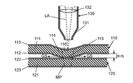
Patent Document 1 will be described with reference to FIG. The two plated steel sheets (the plated steel sheet 110 and the plated steel sheet 120) that are superposed are arranged so that the protruding portions 114 of the plated steel sheet 110 are in line contact with the surface of the plated steel sheet 120. A gap H (0.1 mm or more) is formed between the plated steel plate 110 and the plated steel plate 120 by the protrusion 114. At this time, the gap H is equal to the height h of the protrusion 114. The plated steel plate 110 is irradiated with a laser beam LA. The laser beam LA is irradiated along the groove 116 from the groove 116 side opposite to the top 115 of the protrusion 114, and the plated steel sheet 110 is seam welded. Although the illustration of the overall configuration of the laser device 130 is omitted, the laser beam LA output from the laser generator (not shown) is focused through the lens 132 held by the lens holder 131 and has a high energy density. The plated steel sheet 110 is irradiated as a minute spot. First, the irradiation local part of the plated steel sheet 110 is melted, and then the irradiation local part of the second plated steel sheet 120 is melted. A region indicated by a two-dot chain line in FIG. 8 is a molten pool MP. At this time, the plating layer 112, the plating layer 113, the plating layer 122, and the plating layer 123 are also melted and the metal vapor GS is generated, but the metal vapor GS generated at the joint between the plated steel plate 110 and the plated steel plate 120 is the gap H. Is released into the atmosphere via Therefore, bubbles do not remain in the molten pool MP. The surface of the molten pool MP of the plated steel plate 110 is not disturbed, becomes a smooth surface, and does not cause an undercut.
次に、図9を参照しながら、特許文献2について説明する。めっき鋼板210は、突出部230と突出部231とを有する。そして、めっき鋼板210及びめっき鋼板220を重ね合わせた後、突出部230と突出部231との間の領域R内に、レーザ発生装置(図示せず)から出力されるレーザビーム250を照射して、溶接が行われる。突出部230および突出部231によってめっき鋼板210とめっき鋼板220との間には、すき間Hができている。すき間Hは、突出部の高さhと等しい。めっき鋼板210の突出部230および突出部231の間の領域Rに対し、レーザビーム250は照射される。ビーム照射ノズル251に保持されるレンズ252を通し、焦点をはずした微小スポットとしてレーザビーム250は照射される。レーザビーム250の照射位置は、通常は突出部230と突出部231の中間点に対して行うが、突出部230と突出部231とを除く、突出部230と突出部231の間となる領域R内であれば中間点からずれていても構わない。レーザビーム250の照射により、めっき鋼板210の照射部と、めっき鋼板220の照射部が順に溶融し、溶融池260が形成される。このとき、めっき層212a、212b、222a、222bも溶融して金属蒸気が発生する。めっき層212a、222aから発生する金属蒸気はめっき鋼板210とめっき鋼板220との間に形成される空隙Sを通して大気中に放出される。よって溶融池260に気泡が残留することがない。溶融池260は、溶接完了時点においてブローホールが発生することなく、その表面は滑らかな面となり、溶接強度が一定となる。
Next, Patent Document 2 will be described with reference to FIG. The plated steel sheet 210 has a protrusion 230 and a protrusion 231. Then, after overlapping the plated steel plate 210 and the plated steel plate 220, the region R between the protruding portion 230 and the protruding portion 231 is irradiated with a laser beam 250 output from a laser generator (not shown). Welding is done. A gap H is formed between the plated steel sheet 210 and the plated steel sheet 220 by the protrusion 230 and the protrusion 231. The gap H is equal to the height h of the protrusion. The laser beam 250 is applied to the region R between the protruding portion 230 and the protruding portion 231 of the plated steel sheet 210. The laser beam 250 is irradiated as a minute spot out of focus through a lens 252 held by the beam irradiation nozzle 251. The irradiation position of the laser beam 250 is usually performed at an intermediate point between the protrusion 230 and the protrusion 231, but the region R between the protrusion 230 and the protrusion 231 excluding the protrusion 230 and the protrusion 231. If it is within, it may be shifted from the middle point. By irradiation with the laser beam 250, the irradiated portion of the plated steel plate 210 and the irradiated portion of the plated steel plate 220 are sequentially melted to form a molten pool 260. At this time, the plating layers 212a, 212b, 222a, and 222b are also melted to generate metal vapor. The metal vapor generated from the plating layers 212a and 222a is released into the atmosphere through the gap S formed between the plated steel plate 210 and the plated steel plate 220. Therefore, bubbles do not remain in the molten pool 260. The weld pool 260 has a smooth surface without any blowholes when welding is completed, and the welding strength is constant.
本開示のレーザ溶接制御方法は、第1の鋼板が突出部を有し、第1の鋼板に形成されている突出部の先端と第2の鋼板とが接するように、第1の鋼板と第2の鋼板とを重ね合わせる第1の工程と、第1の工程後に、平面視における突出部の大きさより、大きいサイズの照射パターンで、突出部に向かってレーザ光を照射する第2の工程と、を有する。そして、第1の鋼板の第2の鋼板に対向する面、または、第2の鋼板の第1の鋼板に対向する面、の少なくともいずれか一方の面はめっき加工されている。
In the laser welding control method of the present disclosure, the first steel plate and the second steel plate are in contact with each other so that the first steel plate has a protrusion and the tip of the protrusion formed on the first steel plate is in contact with the second steel plate. A first step of superimposing the two steel plates, and a second step of irradiating laser light toward the protruding portion with an irradiation pattern having a size larger than the size of the protruding portion in plan view after the first step; Have. And at least any one surface of the surface which opposes the 2nd steel plate of a 1st steel plate, or the surface which opposes the 1st steel plate of a 2nd steel plate is plated.
本開示の実施の形態の説明に先立ち、従来のレーザ溶接における問題点を簡単に説明する。
Prior to the description of the embodiment of the present disclosure, problems in conventional laser welding will be briefly described.
上述した特許文献1のレーザ溶接の制御方法では、めっき鋼板110の突出部114がめっき鋼板120の表面に線接触し、めっき鋼板110とめっき鋼板120との間には、すき間H(例えば、H=0.1mm以上)が形成される。なお、めっき鋼板110のめっき鋼板120に対向する面から、突出部114の頂点115までの長さ(突出部114の高さh)は、すき間Hと等しい。めっき鋼板110の溝116に対して、レーザビームLAが照射され、めっき鋼板110およびめっき鋼板120がシーム溶接される。しかしながら、レーザビームLAが照射する際、左右への位置ズレが発生した場合、めっき鋼板110とめっき鋼板120との間にすき間がある部分がレーザ溶接されることがある。
In the laser welding control method of Patent Document 1 described above, the protruding portion 114 of the plated steel plate 110 is in line contact with the surface of the plated steel plate 120, and there is a gap H (for example, H between the plated steel plate 110 and the plated steel plate 120). = 0.1 mm or more) is formed. Note that the length from the surface of the plated steel plate 110 facing the plated steel plate 120 to the apex 115 of the protrusion 114 (height h of the protrusion 114) is equal to the gap H. The groove 116 of the plated steel plate 110 is irradiated with the laser beam LA, and the plated steel plate 110 and the plated steel plate 120 are seam welded. However, when the laser beam LA is irradiated and a positional shift to the left and right occurs, a portion having a gap between the plated steel plate 110 and the plated steel plate 120 may be laser welded.
また、めっき鋼板110に、突出部114以外の突出部(図示せず)が存在する場合、突出部114以外の突出部とめっき鋼板120とが接触し、突出部114とめっき鋼板120とが接触しないことがある。つまり、突出部114とめっき鋼板120との間に、すき間が存在する場合がある。突出部114とめっき鋼板120とのすき間が大きい場合、穴あきといった溶接不良につながる可能性がある。
Moreover, when the protrusion part (not shown) other than the protrusion part 114 exists in the plated steel plate 110, protrusion parts other than the protrusion part 114 and the plated steel plate 120 contact, and the protrusion part 114 and the plated steel plate 120 contact. There are things that do not. That is, there may be a gap between the protruding portion 114 and the plated steel plate 120. When the gap between the protruding portion 114 and the plated steel sheet 120 is large, there is a possibility of leading to poor welding such as perforation.
また、従来の特許文献2のレーザ溶接の制御方法では、めっき鋼板210とめっき鋼板220を重ね合わせた後、めっき鋼板210の突出部230と突出部231との間の領域R内に対し、レーザビーム250を照射して溶接を行う。なお、レーザビーム250は、レーザ発生装置(図示せず)から出力される。そして、めっき鋼板210の突出部230および突出部231がめっき鋼板220の表面に接触し、めっき鋼板210とめっき鋼板220との間には、すき間H(ここではH=0.1mmとする)が形成される。
Further, in the conventional laser welding control method disclosed in Patent Document 2, after the plated steel plate 210 and the plated steel plate 220 are overlapped, the laser is applied to the region R between the protruding portion 230 and the protruding portion 231 of the plated steel plate 210. Welding is performed by irradiating the beam 250. The laser beam 250 is output from a laser generator (not shown). And the protrusion part 230 and the protrusion part 231 of the plated steel plate 210 contact the surface of the plated steel plate 220, and there is a gap H (here, H = 0.1 mm) between the plated steel plate 210 and the plated steel plate 220. It is formed.
しかしながら、ワークセットや治具固定の精度により、突出部230と突出部231の両方が、めっき鋼板220に接触しているとは限らない。例えば一方の突出部(ここでは、突出部230とする)が、めっき鋼板220と接触せず、突出部230の高さh(本実施の形態では0.1mm)以上のすき間Hが、めっき鋼板210とめっき鋼板220との間にできる場合がある。この時、領域R内においても、めっき鋼板210とめっき鋼板220とのすき間Hが突出部230の高さhより大きくなり、穴あきといった溶接不良につながる可能性がある。
However, both the protrusion 230 and the protrusion 231 are not necessarily in contact with the plated steel plate 220 due to the accuracy of work set and jig fixing. For example, one projecting portion (here, projecting portion 230) is not in contact with the plated steel plate 220, and the gap H equal to or higher than the height h (0.1 mm in the present embodiment) of the projecting portion 230 is a plated steel plate. There may be a case between 210 and the plated steel plate 220. At this time, even in the region R, the gap H between the plated steel sheet 210 and the plated steel sheet 220 becomes larger than the height h of the protrusion 230, which may lead to poor welding such as perforation.
なお、すき間H>高さhの状態については、図9には図示していない。
Note that the state of gap H> height h is not shown in FIG.
以下、本開示の実施の形態について、図1から図7を用いて説明する。図1は、レーザ溶接装置の概略構成を示す図である。図2Aは、渦巻き状のレーザ照射を示す図である。図2Bは、渦巻き状の照射パターンにおける突出部12の径aと渦巻き径bとの関係を示す図である。図2Cは、別の突出部の部分図である。図3は、突出部12の径aに対する裕度の一例を示す図である。図4Aは、螺旋状のレーザ照射を示す図である。図4Bは、螺旋状の照射パターンにおける突出部12の幅cと螺旋幅dとの関係を示す図である。図5は突出部12の幅cに対する裕度の一例を示す図である。図6はすき間に対する裕度の一例を示す図で、図7は位置ズレに対する裕度の一例を示す図である。
Hereinafter, embodiments of the present disclosure will be described with reference to FIGS. 1 to 7. FIG. 1 is a diagram showing a schematic configuration of a laser welding apparatus. FIG. 2A is a diagram showing spiral laser irradiation. FIG. 2B is a diagram illustrating a relationship between the diameter a of the protrusion 12 and the spiral diameter b in the spiral irradiation pattern. FIG. 2C is a partial view of another protrusion. FIG. 3 is a diagram illustrating an example of a tolerance for the diameter a of the protrusion 12. FIG. 4A is a diagram showing spiral laser irradiation. FIG. 4B is a diagram illustrating a relationship between the width c of the protrusion 12 and the spiral width d in the spiral irradiation pattern. FIG. 5 is a diagram illustrating an example of a tolerance for the width c of the protrusion 12. FIG. 6 is a diagram illustrating an example of a tolerance for a gap, and FIG. 7 is a diagram illustrating an example of a tolerance for a positional deviation.
(実施の形態1)
本実施の形態について、図1から図3を用いて説明する。 (Embodiment 1)
This embodiment will be described with reference to FIGS.
本実施の形態について、図1から図3を用いて説明する。 (Embodiment 1)
This embodiment will be described with reference to FIGS.
図1に示すレーザ溶接装置は、レーザ溶接を行う装置である。レーザ光を熱源として集光した状態で金属に照射し、金属を局部的に溶融・凝固させることによって接合する装置である。以下では、レーザ溶接装置を用い、亜鉛めっき鋼板のレーザ溶接を行う場合を例にして説明する。
The laser welding apparatus shown in FIG. 1 is an apparatus that performs laser welding. It is an apparatus that joins by irradiating a metal with laser light condensed as a heat source and locally melting and solidifying the metal. Hereinafter, a case where laser welding of a galvanized steel sheet is performed using a laser welding apparatus will be described as an example.
図1に示すレーザ溶接装置は、レーザ発振器1と、ロボット2と、被溶接物である上板10と下板11にレーザ光9を照射するためのレーザ照射用ヘッド7と、レーザ発振器1とロボット2とレーザ照射用ヘッド7等の制御を行うロボットコントローラ3と、レーザ発振器1からレーザ照射用ヘッド7へレーザ光9を伝送する伝送ファイバ8を有する。
A laser welding apparatus shown in FIG. 1 includes a laser oscillator 1, a robot 2, a laser irradiation head 7 for irradiating laser light 9 to an upper plate 10 and a lower plate 11 that are workpieces, a laser oscillator 1, A robot controller 3 that controls the robot 2, the laser irradiation head 7, and the like, and a transmission fiber 8 that transmits laser light 9 from the laser oscillator 1 to the laser irradiation head 7 are provided.
レーザ照射用ヘッド7には、レーザ発振器1および伝送ファイバ8に依存したビーム径のレーザ光9が伝送される。なお、レーザ照射用ヘッド7は、ロボット2に取り付けられている。また、レーザ照射用ヘッド7としては、例えば、ガルバノミラー等の光学機器を用いたものがある。
Laser light 9 having a beam diameter depending on the laser oscillator 1 and the transmission fiber 8 is transmitted to the laser irradiation head 7. The laser irradiation head 7 is attached to the robot 2. As the laser irradiation head 7, for example, there is one using an optical device such as a galvanometer mirror.
ロボットコントローラ3は、溶接条件設定制御部4と、動作制御部5と、レーザ出力制御部6と、を有する。溶接条件設定制御部4は、レーザ溶接条件の設定や他の構成要素への指令等を行う。動作制御部5は、溶接条件設定制御部4で設定された溶接条件や予め教示された動作プログラム等に基づいて、ロボット2またはレーザ照射用ヘッド7の動作を制御する。レーザ出力制御部6は、溶接条件設定制御部4で設定された溶接条件に基づいてレーザ出力を制御するためにレーザ発振器1を制御する。
The robot controller 3 has a welding condition setting control unit 4, an operation control unit 5, and a laser output control unit 6. The welding condition setting control unit 4 performs setting of laser welding conditions, commands to other components, and the like. The operation control unit 5 controls the operation of the robot 2 or the laser irradiation head 7 based on the welding conditions set by the welding condition setting control unit 4 or the operation program taught in advance. The laser output control unit 6 controls the laser oscillator 1 to control the laser output based on the welding conditions set by the welding condition setting control unit 4.
このレーザ溶接装置は、レーザ発振器1からレーザ光9を発振し、レーザ発振器1から発振されたレーザ光9をレーザ照射用ヘッド7内にある集光レンズ(図示せず)によって集束する。そして、集光レンズによって集束されたレーザ光9が、重ね合わせた被溶接物である上板10と下板11とに重ね方向から(図2Aでは上側から)照射され、上板10と下板11は溶接される。
This laser welding apparatus oscillates laser light 9 from the laser oscillator 1 and focuses the laser light 9 oscillated from the laser oscillator 1 by a condenser lens (not shown) in the laser irradiation head 7. Then, the laser beam 9 focused by the condensing lens is irradiated from the overlapping direction (from the upper side in FIG. 2A) to the upper plate 10 and the lower plate 11 which are the objects to be welded, and the upper plate 10 and the lower plate 11 is welded.
次に、図2A、図2B、図2Cを用いて、亜鉛めっき鋼板のレーザ溶接方法について説明する。以下で説明するレーザ溶接は、図1に示すレーザ溶接装置を用いて行われる。
Next, a laser welding method for a galvanized steel sheet will be described with reference to FIGS. 2A, 2B, and 2C. Laser welding described below is performed using the laser welding apparatus shown in FIG.
先ずは、図2A、図2Bを用いて、照射パターンを渦巻き状にレーザ照射しながら溶接する亜鉛めっき鋼板の溶接について説明する。本実施の形態では、上板10および下板11のいずれも、亜鉛めっき鋼板である。なお、上板10および下板11は必ずしも、亜鉛めっき鋼板である必要はない。
First, using FIG. 2A and FIG. 2B, welding of a galvanized steel sheet that is welded while irradiating the irradiation pattern in a spiral shape will be described. In the present embodiment, both the upper plate 10 and the lower plate 11 are galvanized steel plates. Note that the upper plate 10 and the lower plate 11 are not necessarily galvanized steel plates.
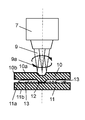
まず、上板10および下板11が重ね合わされる。そして、上板10に予め設けられている突出部12の中心位置からレーザ光9の照射が開始される。レーザ光9の照射は、突出部12の中心から、渦巻き状の照射パターン9aに従って行われる。そして、レーザ光9が渦巻き状の照射パターン9aの外周部分に到達したらレーザ照射は終了する。
First, the upper plate 10 and the lower plate 11 are overlaid. Then, the irradiation of the laser beam 9 is started from the center position of the protruding portion 12 provided in advance on the upper plate 10. The laser beam 9 is irradiated from the center of the protrusion 12 according to the spiral irradiation pattern 9a. When the laser beam 9 reaches the outer peripheral portion of the spiral irradiation pattern 9a, the laser irradiation is finished.
レーザ光9の出力は、亜鉛めっき鋼板である上板10と下板11とを貫通させることができるエネルギー密度である。なお、エネルギー密度およびレーザ出力は、上板10および下板11の板厚に応じて異なり、板厚が厚くなるほど、高エネルギー密度が必要であり、レーザ光9の出力は高く設定される。
The output of the laser beam 9 is an energy density capable of penetrating the upper plate 10 and the lower plate 11 which are galvanized steel plates. The energy density and the laser output vary depending on the plate thicknesses of the upper plate 10 and the lower plate 11, and the higher the plate thickness, the higher the energy density is required, and the higher the output of the laser light 9 is set.
上板10は、亜鉛めっき層10aおよび亜鉛めっき層10bを有し、下板11は亜鉛めっき層11aおよび亜鉛めっき層11bを有する。そして、レーザ光9を照射し、上板10および下板11を溶接する時、亜鉛蒸気13は上板10と下板11とのすき間Hに発生するので、亜鉛蒸気13の影響を受けずに上板10と下板11とを溶接することができる。
The upper plate 10 has a galvanized layer 10a and a galvanized layer 10b, and the lower plate 11 has a galvanized layer 11a and a galvanized layer 11b. When the laser beam 9 is irradiated and the upper plate 10 and the lower plate 11 are welded, the zinc vapor 13 is generated in the gap H between the upper plate 10 and the lower plate 11, so that it is not affected by the zinc vapor 13. The upper plate 10 and the lower plate 11 can be welded.
上述した通り、本実施の形態のレーザ溶接方法では、図2Bに示すように、亜鉛めっき鋼板である上板10に予め設けた円形状の突出部12の中心位置から突出部12より大きい照射パターン9aで、渦巻き状に溶接することにより、亜鉛めっき鋼板である上板10および下板11との重ね合わせ面から亜鉛蒸気13の排出経路を作り出すことができる。
As described above, in the laser welding method of the present embodiment, as shown in FIG. 2B, an irradiation pattern larger than the protrusion 12 from the center position of the circular protrusion 12 provided in advance on the upper plate 10 that is a galvanized steel sheet. In 9a, the discharge path of the zinc vapor 13 can be created from the overlapping surface of the upper plate 10 and the lower plate 11 which are galvanized steel plates by welding spirally.
なお、本開示において、円形状は、円状と長円状とを含む。
In the present disclosure, the circular shape includes a circular shape and an oval shape.
また、良好な溶接を行うためには、当然ながら、適正な条件が必要となる。
Moreover, in order to perform good welding, of course, appropriate conditions are required.
ここで、上板10および下板11との位置関係について、図2Bおよび図2Cを参照しながら説明する。
Here, the positional relationship between the upper plate 10 and the lower plate 11 will be described with reference to FIGS. 2B and 2C.
例えば、上板10が複数の突出部12を有する場合、設計精度によっては、全ての突出部12が下板11と接するとは限らない。突出部12が下板11と接する場合の位置関係を図2Bに示し、突出部12が下板11と接しない場合の位置関係を図2Cに示す。なお、図2Cは、図2Bの破線で囲んでいる領域に対応する箇所のみ示し、他の構成については図示を省略している。
For example, when the upper plate 10 has a plurality of protrusions 12, not all the protrusions 12 are in contact with the lower plate 11 depending on the design accuracy. FIG. 2B shows the positional relationship when the protruding portion 12 is in contact with the lower plate 11, and FIG. 2C shows the positional relationship when the protruding portion 12 is not in contact with the lower plate 11. Note that FIG. 2C shows only the portion corresponding to the region surrounded by the broken line in FIG. 2B, and the other components are not shown.
図2Bに示すように、突出部12と下板11とが接している場合は、突出部12の高さ(以下、『高さh』と記す)と、上板10の下板11に対向する面と、下板11の上板10に対向する面との間の長さ(以下、『すき間H』と記す)は、等しい。
As shown in FIG. 2B, when the protruding portion 12 and the lower plate 11 are in contact with each other, the height of the protruding portion 12 (hereinafter referred to as “height h”) is opposed to the lower plate 11 of the upper plate 10. The length between the surface to be faced and the surface facing the upper plate 10 of the lower plate 11 (hereinafter referred to as “clearance H”) is equal.
一方、図2Cに示すように、突出部12と下板11とが接していない場合は、突出部12の高さをhとすると、高さhとすき間Hは等しくはない。突出部12の先端と、下板11の上板10に対向する面との間の長さをすき間h’とすると、H=h+h’となる。
On the other hand, as shown in FIG. 2C, when the protrusion 12 and the lower plate 11 are not in contact with each other, if the height of the protrusion 12 is h, the height h and the gap H are not equal. If the length between the tip of the projecting portion 12 and the surface facing the upper plate 10 of the lower plate 11 is a gap h ′, H = h + h ′.
次に、図3を用いて、平面視における突出部12の径aに対する渦巻き状の照射パターン9aの渦巻き径bの適正範囲について説明する。なお、図3は一例であり、本開示はこれに限定させるものではない。
Next, an appropriate range of the spiral diameter b of the spiral irradiation pattern 9a with respect to the diameter a of the protrusion 12 in plan view will be described with reference to FIG. Note that FIG. 3 is an example, and the present disclosure is not limited to this.
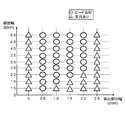
図3に示す施工評価の際の条件は以下の通りである。上板10および下板11として、めっきの被膜密度が45g/m2、板厚が0.8mmである亜鉛めっき鋼板を用いた。すき間h’=0mm、突出部12の高さh=0.1mmとした。溶接条件は、出力が2.5kW、速度が6m/minとした。横軸を上板10が有する突出部12の径aの長さとし、縦軸を照射パターン9aの渦巻き径bとした。
The conditions for the construction evaluation shown in FIG. 3 are as follows. As the upper plate 10 and the lower plate 11, galvanized steel plates having a coating film density of 45 g / m 2 and a plate thickness of 0.8 mm were used. The gap h ′ was set to 0 mm, and the height h of the protrusion 12 was set to 0.1 mm. The welding conditions were an output of 2.5 kW and a speed of 6 m / min. The horizontal axis is the length of the diameter a of the protrusion 12 of the upper plate 10, and the vertical axis is the spiral diameter b of the irradiation pattern 9a.
図3に示す施工評価の結果から、溶接結果が良好となる適正範囲が分かる。図3には、溶接具合の結果を○と△で表している。目視で確認を行い、○はビード外観が良好な場合を示し、△は気孔が残存している場合を示している。突出部12の径aが2.5mm以下においては、突出部12の径aに対して渦巻き径bを大きく設定していれば、亜鉛蒸気13の排出経路が確保され、良好なビード外観を得ることができることがわかる。具体的には、突出部12の径aに対して渦巻き径bを0.5mm以上大きくすれば良い。
From the results of the construction evaluation shown in FIG. 3, the appropriate range in which the welding results are good is known. In FIG. 3, the result of the welding condition is represented by ◯ and Δ. Visual confirmation was carried out, ◯ indicates a case where the bead appearance is good, and Δ indicates a case where pores remain. When the diameter a of the protruding portion 12 is 2.5 mm or less, if the spiral diameter b is set larger than the diameter a of the protruding portion 12, a discharge path for the zinc vapor 13 is secured, and a good bead appearance is obtained. You can see that Specifically, the spiral diameter b may be larger than the diameter a of the protrusion 12 by 0.5 mm or more.
例えば、突出部12の径aが0.5mmであれば、渦巻き径bは1.0mm以上、突出部12の径aが2.5mmであれば、渦巻き径bは3.0mm以上必要になる。しかし、突出部12の径aが3.0mm以上になると、上板10と下板11との接触面積が増加する。接触面積の増加により、突出部12を設けた効果がなくなる。その結果、亜鉛蒸気13の排出が難しい状態になり、溶接ビード内や溶接ビード表面にブローホールやピットが残存することになる。
For example, if the diameter a of the protrusion 12 is 0.5 mm, the spiral diameter b is 1.0 mm or more, and if the diameter a of the protrusion 12 is 2.5 mm, the spiral diameter b is 3.0 mm or more. . However, when the diameter a of the protrusion 12 is 3.0 mm or more, the contact area between the upper plate 10 and the lower plate 11 increases. Due to the increase in the contact area, the effect of providing the protrusion 12 is lost. As a result, it becomes difficult to discharge the zinc vapor 13, and blow holes and pits remain in the weld bead and on the weld bead surface.
(実施の形態2)
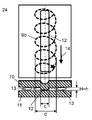
次に図4A、図4Bを用いて、突出部12の平面視における形状がライン状の場合について説明する。本実施の形態では、照射パターン9bは、溶接方向14に移動する回転中心を周回する螺旋形状を有する軌跡に沿って、溶接対象物に対して相対的に移動する。つまり、実施の形態1では、照射パターン9aが渦巻き状であるのに対し、本実施の形態では、照射パターン9bが螺旋状である。また、実施の形態1では、突出部12が円形状であるのに対し、本実施の形態では、突出部12はライン状である。本実施の形態では、螺旋状にレーザ照射しながらライン状の突出部に対して溶接する亜鉛めっき鋼板の溶接について説明する。なお、実施の形態1と同様の構成については同一の符号を付して説明を省略する場合がある。 (Embodiment 2)
Next, the case where the shape of theprotrusion 12 in a plan view is a line shape will be described with reference to FIGS. 4A and 4B. In this Embodiment, the irradiation pattern 9b moves relatively with respect to a welding target object along the locus | trajectory which has the spiral shape which goes around the rotation center which moves to the welding direction 14. FIG. That is, in the first embodiment, the irradiation pattern 9a is spiral, whereas in the present embodiment, the irradiation pattern 9b is spiral. Further, in the first embodiment, the protruding portion 12 has a circular shape, whereas in the present embodiment, the protruding portion 12 has a line shape. In the present embodiment, welding of a galvanized steel sheet that is welded to a line-shaped protrusion while irradiating laser in a spiral manner will be described. In addition, about the structure similar to Embodiment 1, the same code | symbol may be attached | subjected and description may be abbreviate | omitted.
次に図4A、図4Bを用いて、突出部12の平面視における形状がライン状の場合について説明する。本実施の形態では、照射パターン9bは、溶接方向14に移動する回転中心を周回する螺旋形状を有する軌跡に沿って、溶接対象物に対して相対的に移動する。つまり、実施の形態1では、照射パターン9aが渦巻き状であるのに対し、本実施の形態では、照射パターン9bが螺旋状である。また、実施の形態1では、突出部12が円形状であるのに対し、本実施の形態では、突出部12はライン状である。本実施の形態では、螺旋状にレーザ照射しながらライン状の突出部に対して溶接する亜鉛めっき鋼板の溶接について説明する。なお、実施の形態1と同様の構成については同一の符号を付して説明を省略する場合がある。 (Embodiment 2)
Next, the case where the shape of the
本実施の形態のレーザ溶接装置は、上板10および下板11のいずれも亜鉛めっき鋼板で形成されている。なお、上板10および下板11は必ずしも、亜鉛めっき鋼板である必要はない。
In the laser welding apparatus of the present embodiment, both the upper plate 10 and the lower plate 11 are formed of a galvanized steel plate. Note that the upper plate 10 and the lower plate 11 are not necessarily galvanized steel plates.
まず、上板10および下板11が重ね合わされる。そして、上板10に予め設けた突出部12の中心位置からレーザ光9の照射が開始される。レーザ光9の照射は、突出部12の中心位置から、螺旋状の照射パターン9bに従って行われる。突出部12の中心位置を基準に突出部12の幅cよりも大きい螺旋幅dのレーザ照射にて溶接を行う。
First, the upper plate 10 and the lower plate 11 are overlaid. Then, the irradiation of the laser beam 9 is started from the center position of the protrusion 12 provided in advance on the upper plate 10. The laser beam 9 is irradiated from the center position of the protrusion 12 according to the spiral irradiation pattern 9b. Welding is performed by laser irradiation with a spiral width d larger than the width c of the protrusion 12 with the center position of the protrusion 12 as a reference.
レーザ光9の出力は、亜鉛めっき鋼板である上板10と下板11を貫通させることができるエネルギー密度である。なお、エネルギー密度およびレーザ出力は、上板10および下板11の板厚に応じて異なり、板厚が厚くなるほど、高エネルギー密度が必要であり、レーザ光9の出力は高く設定される。
The output of the laser beam 9 is an energy density that can penetrate the upper plate 10 and the lower plate 11 that are galvanized steel plates. The energy density and the laser output vary depending on the plate thicknesses of the upper plate 10 and the lower plate 11, and the higher the plate thickness, the higher the energy density is required, and the higher the output of the laser light 9 is set.
上板10は、亜鉛めっき層10aおよび亜鉛めっき層10bを有し、下板11は、亜鉛めっき層11aおよび亜鉛めっき層11bを有する。そして、レーザ光9を照射し、上板10および下板11を溶接することにより、すき間Hから亜鉛蒸気13が発生し、亜鉛蒸気の影響を受けずに溶接することができる。
The upper plate 10 has a galvanized layer 10a and a galvanized layer 10b, and the lower plate 11 has a galvanized layer 11a and a galvanized layer 11b. Then, by irradiating the laser beam 9 and welding the upper plate 10 and the lower plate 11, zinc vapor 13 is generated from the gap H, and welding can be performed without being affected by the zinc vapor.
上述した通り、本実施の形態のレーザ溶接方法では、図4Bに示すように、亜鉛めっき鋼板である上板10に予め設けたライン状の突出部12の中心位置から突出部12の幅より大きい螺旋幅の照射パターンで、螺旋状にレーザ照射して溶接することにより、亜鉛めっき鋼板である上板10および下板11との重ね合わせ面から亜鉛蒸気13の排出経路を作り出すことができる。
As described above, in the laser welding method of the present embodiment, as shown in FIG. 4B, the width is larger than the width of the protruding portion 12 from the center position of the line-shaped protruding portion 12 provided in advance on the upper plate 10 that is a galvanized steel plate. A discharge path of the zinc vapor 13 can be created from the overlapping surface of the upper plate 10 and the lower plate 11 which are galvanized steel plates by welding with laser irradiation in a spiral shape with an irradiation pattern having a spiral width.
なお、良好な溶接を行うためには、当然ながら、適正な条件が必要となる。
In order to perform good welding, of course, appropriate conditions are required.
次に、図5を用いて、平面視における突出部12のライン幅である突出部12の幅cに対する螺旋幅dの適正範囲について説明する。なお、図5は一例であり、本開示はこれに限定されるものではない。
Next, an appropriate range of the spiral width d with respect to the width c of the protrusion 12 that is the line width of the protrusion 12 in plan view will be described with reference to FIG. Note that FIG. 5 is an example, and the present disclosure is not limited to this.
図5に示す施工評価の際の条件は以下の通りである。
The conditions for the construction evaluation shown in FIG. 5 are as follows.
上板10および下板11として、めっきの被膜密度が45g/m2、板厚が0.8mmである亜鉛めっき鋼板を用いた。すき間h’=0mm、突出部12の高さh=0.1mmとした。溶接条件は、出力が2.5kW、速度が2m/minとした。横軸を上板10が有する突出部12の幅cの長さとし、縦軸を照射パターン9bの螺旋幅dとした。
As the upper plate 10 and the lower plate 11, galvanized steel plates having a coating film density of 45 g / m 2 and a plate thickness of 0.8 mm were used. The gap h ′ was set to 0 mm, and the height h of the protrusion 12 was set to 0.1 mm. The welding conditions were an output of 2.5 kW and a speed of 2 m / min. The horizontal axis is the length of the width c of the protrusion 12 of the upper plate 10, and the vertical axis is the spiral width d of the irradiation pattern 9b.
図5に示す施工評価の結果から、溶接結果が良好となる適正範囲が分かる。図5には、溶接具合の結果を○と△で表している。目視で確認を行い、○はビード外観が良好な場合を示し、△は気孔が残存している場合を示している。突出部12の幅cが2.0mm以下においては、幅cに対して螺旋幅dを大きく設定していれば亜鉛蒸気13の排出経路が確保され、良好なビード外観を得ることができることを表している。具体的には、突出部12の幅cに対して螺旋幅dを0.5mm以上大きくすれば良い。
From the results of the construction evaluation shown in FIG. 5, the appropriate range in which the welding result is good is known. In FIG. 5, the result of the welding condition is represented by ◯ and Δ. Visual confirmation was carried out, ◯ indicates a case where the bead appearance is good, and Δ indicates a case where pores remain. When the width c of the protrusion 12 is 2.0 mm or less, if the spiral width d is set larger than the width c, a discharge path for the zinc vapor 13 is secured, and a good bead appearance can be obtained. ing. Specifically, the spiral width d may be larger than the width c of the protrusion 12 by 0.5 mm or more.
例えば、幅cが0.5mmであれば螺旋幅dは1.0mm以上、幅cが2.0mmであれば螺旋幅dは2.5mm以上必要になる。しかし、突出部12の径aが2.5mm以上になると、亜鉛めっき鋼板である上板10に設けた突出部12と下板11との接触面積が増加する。この接触面積の増加により、突出部12を設けた効果がなくなり、亜鉛蒸気13の排出が難しい状態になり、溶接ビード内や溶接ビード表面にブローホールやピットが残存することになる。
For example, if the width c is 0.5 mm, the spiral width d is 1.0 mm or more, and if the width c is 2.0 mm, the spiral width d is 2.5 mm or more. However, when the diameter a of the protrusion 12 is 2.5 mm or more, the contact area between the protrusion 12 provided on the upper plate 10 that is a galvanized steel sheet and the lower plate 11 increases. Due to this increase in the contact area, the effect of providing the protruding portion 12 is lost, and the discharge of the zinc vapor 13 becomes difficult, and blow holes and pits remain in the weld bead and on the weld bead surface.
[すき間の裕度]
図6を用いて、螺旋状にレーザ照射しながら溶接する亜鉛めっき鋼板の溶接に対するすき間の裕度の広さについて、以下に説明する。 [Tolerance of gaps]
With reference to FIG. 6, a description will be given below of the width of a clearance for welding a galvanized steel sheet that is welded while being irradiated with a laser beam in a spiral manner.
図6を用いて、螺旋状にレーザ照射しながら溶接する亜鉛めっき鋼板の溶接に対するすき間の裕度の広さについて、以下に説明する。 [Tolerance of gaps]
With reference to FIG. 6, a description will be given below of the width of a clearance for welding a galvanized steel sheet that is welded while being irradiated with a laser beam in a spiral manner.
図6は、すき間に対する施工裕度の広さについて、横軸に溶接法(特許文献1及び2と本開示との比較)を示し、縦軸にすき間h’を示し、施工評価を行った評価結果である。なお、この施工評価は、上板および下板として、めっきの被膜密度が45g/m2である亜鉛めっき鋼板の板厚0.8mmを用いた。突出部の高さhが0.1mm、突出部の幅が0.5mmとした。図6に、溶接結果が良好となる適正範囲を示している。
FIG. 6 shows an evaluation of the construction tolerance with respect to the clearance, in which the horizontal axis indicates the welding method (Comparison between Patent Documents 1 and 2 and this disclosure), the vertical axis indicates the clearance h ′, and the construction evaluation is performed. It is a result. In this construction evaluation, a plate thickness of 0.8 mm of a galvanized steel sheet having a coating film density of 45 g / m 2 was used as the upper plate and the lower plate. The height h of the protruding portion was 0.1 mm, and the width of the protruding portion was 0.5 mm. FIG. 6 shows an appropriate range in which the welding result is good.
図8に示す特許文献1においては、ライン状の突出部114の上方からライン状にレーザ照射するライン溶接の溶接法なので、突出部114の先端と、めっき鋼板120とのすき間h’は0.3mmが限界である。なお、図8には、すき間h’を有する構成は図示していない。
In Patent Document 1 shown in FIG. 8, since the welding method is line welding in which laser irradiation is performed in a line shape from above the line-shaped protrusion 114, the gap h ′ between the tip of the protrusion 114 and the plated steel sheet 120 is 0. 3 mm is the limit. Note that FIG. 8 does not show a configuration having a gap h ′.
なぜなら、ライン溶接ではビード幅が狭く、限界値を超えるすき間h’に必要とする溶融金属量を確保できないためである。
This is because the bead width is narrow in line welding, and the amount of molten metal required for the gap h 'exceeding the limit value cannot be secured.
図9に示す特許文献2においては、突出部230と突出部231との間をライン状にレーザ照射する溶接法なので、突出部230と突出部231との間の領域には、始めから突出部230(または突出部231)の高さhによる0.1mmのすき間がある。突出部230と突出部231との間の領域におけるめっき鋼板210とめっき鋼板220とのすき間Hは0.3mmが限界となる。つまり、突出部230の先端(または突出部231の先端)とめっき鋼板220とのすき間h’は0.2mmが限界となる。特許文献1と同様に、ライン状にレーザ照射するライン溶接ではビード幅が狭く、限界値を超えるすき間h’に必要な溶融金属量を確保できないためである。なお、図9には、すき間h’を有する構成は図示していない。
In patent document 2 shown in FIG. 9, since it is a welding method which laser-irradiates between the protrusion part 230 and the protrusion part 231 in a line form, in the area | region between the protrusion part 230 and the protrusion part 231, a protrusion part is from the beginning. There is a gap of 0.1 mm depending on the height h of 230 (or the protruding portion 231). In the region between the protrusion 230 and the protrusion 231, the gap H between the plated steel sheet 210 and the plated steel sheet 220 is limited to 0.3 mm. That is, the limit of the gap h ′ between the tip of the protrusion 230 (or the tip of the protrusion 231) and the plated steel plate 220 is limited to 0.2 mm. This is because, as in Patent Document 1, line welding in which laser irradiation is performed in a line shape has a narrow bead width, and the amount of molten metal necessary for the gap h 'exceeding the limit value cannot be secured. Note that FIG. 9 does not show a configuration having a gap h ′.
一方、図4Aから図5を参照しながら説明した本開示の螺旋状の溶接では、突出部12上に螺旋状の溶接をすることにより、突出部12と対応するめっき鋼板(下板11)とのすき間h’を0.5mmまで広げても問題はない。なぜなら、実施の形態2の溶接方法では、レーザを螺旋状に照射することにより、ライン状に照射するライン溶接よりもビード幅が広くなるようするため溶融金属量を多く確保できる。よって、突出部12と対応するめっき鋼板(下板11)とのすき間h’に必要な溶融金属量を確保できる。
On the other hand, in the helical welding of the present disclosure described with reference to FIGS. 4A to 5, by performing helical welding on the protruding portion 12, the plated steel plate (lower plate 11) corresponding to the protruding portion 12 There is no problem even if the gap h ′ is widened to 0.5 mm. This is because, in the welding method of the second embodiment, by irradiating the laser in a spiral shape, the bead width becomes wider than the line welding that irradiates in a line shape, so that a large amount of molten metal can be secured. Therefore, it is possible to secure the amount of molten metal necessary for the gap h ′ between the protruding portion 12 and the corresponding plated steel plate (lower plate 11).
なお、板厚が0.8mmの上板10および板厚が0.8mmの下板11を重ね合わせることによるすき間の許容率は、特許文献1や特許文献2のようなライン状にレーザを照射するライン溶接では板厚に対して約1/3相当であるのに対して、本開示の螺旋状にレーザを照射するラインの溶接では板厚の約2/3相当であり、裕度を約1.7倍にできる。
In addition, the clearance rate by overlapping the upper plate 10 with a plate thickness of 0.8 mm and the lower plate 11 with a plate thickness of 0.8 mm is such that the laser is irradiated in a line shape as in Patent Document 1 and Patent Document 2. In line welding, which is equivalent to about 1/3 of the plate thickness, in the welding of the line in which the laser is irradiated in a spiral shape of the present disclosure, it is equivalent to about 2/3 of the plate thickness, and the tolerance is about 1.7 times.
[位置ズレの裕度]
次に、図7を用いて、螺旋状にレーザ照射しながら溶接する亜鉛めっき鋼板の溶接に対する位置ズレ裕度の広さについて、一例を以下に説明する。 [Position tolerance]
Next, with reference to FIG. 7, an example of the width of the positional deviation tolerance with respect to the welding of the galvanized steel sheet that is welded while irradiating laser in a spiral shape will be described below.
図7は、位置ズレに対する施工裕度の広さについて、横軸に溶接法(特許文献1及び2と本開示との比較)を示し、縦軸に位置ズレを示し、施工評価を行った評価結果である。なお、この施工評価は、上板および下板として、めっきの被膜密度45g/m2である亜鉛めっき鋼板の板厚0.8mmが用いられた。突出部の高さhが0.1mm、突出部の幅が0.5mmである。図7に、溶接結果が良好となる適正範囲を示している。
FIG. 7 shows an evaluation of the construction tolerance with respect to the positional deviation, in which the horizontal axis indicates the welding method (Comparison between Patent Documents 1 and 2 and the present disclosure), the vertical axis indicates the positional deviation, and the construction evaluation is performed. It is a result. In this construction evaluation, a plate thickness of 0.8 mm of a galvanized steel plate having a coating film density of 45 g / m 2 was used as the upper plate and the lower plate. The height h of the protrusion is 0.1 mm, and the width of the protrusion is 0.5 mm. FIG. 7 shows an appropriate range in which the welding result is good.
図8に示す特許文献1においては、突出部114の上方からレーザ照射する溶接法なので、突出部114の中心から突出部114の幅である0.5mmから外れると、突出部114のない箇所(めっき鋼板110とめっき鋼板120とのすき間Hの領域)になるため、穴あきが発生しやすくなる。
In patent document 1 shown in FIG. 8, since it is the welding method which laser-irradiates from the upper direction of the protrusion part 114, if it remove | deviates from 0.5 mm which is the width | variety of the protrusion part 114 from the center of the protrusion part 114, the location ( Since it becomes a gap H region between the plated steel plate 110 and the plated steel plate 120, perforation is likely to occur.
図9に示す特許文献2においては、一定のすき間Hが形成されている突出部230と突出部231との間にレーザ照射する溶接法なので、溶接箇所が突出部230と突出部231と間の板厚方向のすき間が一定のすき間Hの領域内であれば、問題なく、溶接することができる。
In Patent Document 2 shown in FIG. 9, since the welding method involves laser irradiation between the protruding portion 230 and the protruding portion 231 in which a certain gap H is formed, the welding point is between the protruding portion 230 and the protruding portion 231. If the gap in the plate thickness direction is within a certain gap H region, welding can be performed without any problem.
一方、図4Aから図5を参照しながら説明した本開示の螺旋状の溶接では、螺旋状の螺旋幅dに応じて位置ズレ裕度が異なる。本開示の溶接方法では、突出部12の幅cに対して螺旋幅dを0.5mm以上大きく設定していれば、良好なビード外観を得ることができる。つまり、螺旋幅dを大きくすればより位置ズレ裕度は広くなる。図7に示すように例えば、螺旋幅dが2mmの場合、位置ズレは突出部中心から±1mm、螺旋幅dが3mmでは位置ズレは突出部中心から±2mm、螺旋幅dが4mmでは位置ズレは突出部中心から±3mmまで可能である。絶えず、亜鉛蒸気の排出がしやすい状態であり、溶接ビード内や溶接ビード表面にブローホールやピットが残存することを抑制することができる。
On the other hand, in the helical welding of the present disclosure described with reference to FIGS. 4A to 5, the positional deviation tolerance varies depending on the helical width d. In the welding method of the present disclosure, a good bead appearance can be obtained if the spiral width d is set larger by 0.5 mm or more than the width c of the protrusion 12. That is, if the spiral width d is increased, the positional deviation tolerance becomes wider. As shown in FIG. 7, for example, when the spiral width d is 2 mm, the positional deviation is ± 1 mm from the center of the protrusion, the positional deviation is ± 2 mm from the center of the protrusion when the spiral width d is 3 mm, and the positional deviation when the spiral width d is 4 mm. Can be ± 3 mm from the center of the protrusion. It is in a state where zinc vapor is easily discharged constantly, and it is possible to suppress the remaining of blow holes and pits in the weld bead and on the weld bead surface.
以上の説明から明らかなように、本開示のレーザ溶接方法では、上板10が突出部12を有し、上板10に形成されている突出部12の先端と、下板11とが接するように、上板10と下板11とを重ね合わせる。更に、平面視で、突出部12より大きいサイズの照射パターン9bで螺旋状にレーザ照射し、少なくとも一方がめっき鋼板からなる溶接対象物(上板10および下板11)を重ね合わせ溶接している。これにより、少なくとも一方の鋼板に突出部12を形成し、突出部12と対向する下板11に接するように、上板10および下板11を重ね合わせて行われる溶接において、位置ズレの裕度を確保することができる。更に、突出部12と突出部12に対向するめっき鋼板(下板11)とのすき間h’の裕度を向上させることができる。つまり、突出部12と対応するめっき鋼板(下板11)とのすき間h’と、螺旋幅の大きさに応じての位置ズレと、の両方における施工の裕度を向上させることができる。
As is clear from the above description, in the laser welding method of the present disclosure, the upper plate 10 has the protruding portion 12 so that the tip of the protruding portion 12 formed on the upper plate 10 is in contact with the lower plate 11. In addition, the upper plate 10 and the lower plate 11 are overlapped. Further, in planar view, laser irradiation is performed spirally with an irradiation pattern 9b having a size larger than the protrusion 12, and at least one of the welding objects (upper plate 10 and lower plate 11) made of a plated steel plate is overlapped and welded. . Thereby, in the welding performed by overlapping the upper plate 10 and the lower plate 11 so that the protruding portion 12 is formed on at least one of the steel plates and is in contact with the lower plate 11 facing the protruding portion 12, the margin of positional deviation. Can be secured. Furthermore, the tolerance of the gap h ′ between the protruding portion 12 and the plated steel plate (lower plate 11) facing the protruding portion 12 can be improved. That is, it is possible to improve the tolerance of construction in both the gap h ′ between the protruding portion 12 and the corresponding plated steel plate (lower plate 11) and the positional deviation according to the size of the spiral width.
なお、突出部12上にデフォーカスによる突出部12の外形より大きいサイズのビード幅となるレーザ光を照射して溶接を行う方法の場合、エネルギー密度はビード中心が高く、ビード際に近づくにつれてエネルギー密度は低い状態になる。従って、ビード中心付近は溶け込みが深く、ビード際付近は浅くなり、ビード幅全体の溶け込みを均一にさせることはできない。本開示の螺旋状にレーザ照射する溶接では、キーホール溶接による螺旋状にレーザ照射することで、ビード幅全体の溶け込みを均一に近づけることができ、溶接性を向上させることができる。
In the case of welding by irradiating a laser beam having a larger bead width than the outer shape of the projecting portion 12 by defocusing on the projecting portion 12, the energy density is higher at the center of the bead, and the energy becomes closer to the bead. The density is low. Therefore, the penetration near the center of the bead is deep and the vicinity near the bead becomes shallow, so that the entire penetration of the bead width cannot be made uniform. In welding with laser irradiation in the spiral form of the present disclosure, laser irradiation in a spiral form by keyhole welding can bring the entire bead width into a uniform penetration, and weldability can be improved.
本開示によれば、亜鉛メッキ鋼板等の表面処理が行われた鋼板の溶接において、レーザ溶接を行う際、突出部12上に、突出部より大きい所定のサイズの照射パターンで、渦巻き状や螺旋状にレーザ照射することで溶接時には亜鉛蒸気の影響を受けることを防止し、かつ、位置ズレやギャップを気にすることなく溶接を行うことができる。よって、溶接ビード内や溶接ビード表面に生じる気孔を抑制することができ、溶接性を向上することができる。
According to the present disclosure, when performing laser welding in welding of steel sheets that have been surface-treated, such as galvanized steel sheets, a spiral or spiral pattern is formed on the protrusion 12 with an irradiation pattern having a predetermined size larger than the protrusion. By performing laser irradiation in a shape, it is possible to prevent the influence of zinc vapor during welding and to perform welding without worrying about misalignment or gaps. Therefore, pores generated in the weld bead or the weld bead surface can be suppressed, and the weldability can be improved.
なお、本開示は、螺旋状の照射パターン9bだけではなく、前述している渦巻き状の照射パターン9aについても同様の効果を得ることができる。
In addition, this indication can acquire the same effect not only about the spiral irradiation pattern 9b but the spiral irradiation pattern 9a mentioned above.
以上のように、本開示のレーザ溶接方法は、上板10が突出部12を有し、上板10に形成されている突出部12の先端と、下板11とが接するように、上板10と下板11とを重ね合わせる第1の工程を有する。更に、本開示のレーザ溶接方法は、第1の工程後に、平面視における突出部12の大きさより、大きいサイズの照射パターン9a(または9b)で、突出部12に向かってレーザ光を照射する第2の工程を有する。そして、上板10の下板11に対向する面、または、下板11の上板10に対向する面、の少なくともいずれか一方の面はめっき加工されている。
As described above, according to the laser welding method of the present disclosure, the upper plate 10 has the protruding portion 12, and the upper plate 10 is in contact with the tip of the protruding portion 12 formed on the upper plate 10 and the lower plate 11. 10 and the lower plate 11 are superposed on each other. Furthermore, in the laser welding method of the present disclosure, after the first step, the laser beam is irradiated toward the protruding portion 12 with the irradiation pattern 9a (or 9b) having a size larger than the size of the protruding portion 12 in plan view. It has two steps. Then, at least one surface of the surface facing the lower plate 11 of the upper plate 10 or the surface facing the upper plate 10 of the lower plate 11 is plated.
よって、本開示のレーザ溶接方法では、亜鉛めっきの亜鉛蒸気を円滑に排出し、亜鉛蒸気の影響を受けることなく、良好な溶接することができる。溶接ビード内や溶接ビード表面に生じる気孔を抑制することができ、溶接性を向上することができる。
Therefore, in the laser welding method of the present disclosure, the zinc vapor of galvanization can be smoothly discharged, and good welding can be performed without being affected by the zinc vapor. The pores generated in the weld bead or the weld bead surface can be suppressed, and the weldability can be improved.
なお、本実施の形態では、突出部12を上板10に設けた例で説明してきたが、下板11に突出部12を設けても良い。
In addition, in this Embodiment, although the example which provided the protrusion part 12 in the upper board 10 was demonstrated, you may provide the protrusion part 12 in the lower board 11. FIG.
また、本実施の形態では、亜鉛めっき鋼板を用いた例について説明した。しかし、鋼板よりも融点が低い沸点である金属めっきが施された鋼板であれば、どのような表面処理鋼板でも適用可能である。
Further, in the present embodiment, an example using a galvanized steel sheet has been described. However, any surface-treated steel sheet can be used as long as it is a steel sheet on which metal plating having a boiling point lower than that of the steel sheet is applied.
以上のように、本開示によれば、亜鉛メッキ鋼板等の表面処理が行われた鋼板の溶接において、上板10または下板11に設けた突出部12上に突出部12より大きいサイズの照射パターンで、渦巻き状または螺旋状にレーザ溶接を行うことにより、蒸気(亜鉛めっきの亜鉛蒸気など)を円滑に排出し、蒸気の影響を受けることなく、良好な溶接することができる。よって、溶接ビード内や溶接ビード表面に生じる気孔を抑制することができ、溶接性を向上することができるので、表面処理が行われた部材を溶接するレーザ溶接制御方法およびレーザ溶接装置として産業上有用である。
As described above, according to the present disclosure, in welding of a steel plate subjected to surface treatment such as a galvanized steel plate, irradiation with a size larger than the protruding portion 12 is provided on the protruding portion 12 provided on the upper plate 10 or the lower plate 11. By performing laser welding in a spiral or spiral pattern, steam (such as zinc-plated zinc steam) can be discharged smoothly, and good welding can be achieved without being affected by steam. Therefore, pores generated in the weld bead or on the surface of the weld bead can be suppressed and weldability can be improved. Therefore, the laser welding control method and the laser welding apparatus for welding the surface-treated member are industrially used. Useful.
1 レーザ発振器
2 ロボット
3 ロボットコントローラ
4 溶接条件設定制御部
5 動作制御部
6 レーザ出力制御部
7 レーザ照射用ヘッド
8 伝送ファイバ
9 レーザ光
9a,9b 照射パターン
10 上板
10a,10b 亜鉛めっき層
11a,11b 亜鉛めっき層
11 下板
12,114,230,231 突出部
13 亜鉛蒸気
14 溶接方向
116 溝
GS 金属蒸気
H すき間
R 領域
h 高さ
h’ すき間 DESCRIPTION OF SYMBOLS 1Laser oscillator 2 Robot 3 Robot controller 4 Welding condition setting control part 5 Operation control part 6 Laser output control part 7 Laser irradiation head 8 Transmission fiber 9 Laser light 9a, 9b Irradiation pattern 10 Upper plate 10a, 10b Zinc plating layer 11a, 11b Zinc plating layer 11 Lower plate 12, 114, 230, 231 Protrusion 13 Zinc vapor 14 Welding direction 116 Groove GS Metal vapor H Clearance R region h Height h 'Clearance
2 ロボット
3 ロボットコントローラ
4 溶接条件設定制御部
5 動作制御部
6 レーザ出力制御部
7 レーザ照射用ヘッド
8 伝送ファイバ
9 レーザ光
9a,9b 照射パターン
10 上板
10a,10b 亜鉛めっき層
11a,11b 亜鉛めっき層
11 下板
12,114,230,231 突出部
13 亜鉛蒸気
14 溶接方向
116 溝
GS 金属蒸気
H すき間
R 領域
h 高さ
h’ すき間 DESCRIPTION OF SYMBOLS 1
Claims (5)
- 第1の鋼板が突出部を有し、前記第1の鋼板に形成されている前記突出部の先端と、第2の鋼板とが接するように、前記第1の鋼板と前記第2の鋼板とを重ね合わせる第1の工程と、
前記第1の工程後に、平面視における前記突出部の大きさより、大きいサイズの照射パターンで、前記突出部に向かって前記レーザ光を照射する第2の工程と、
を備え、
前記第1の鋼板の前記第2の鋼板に対向する面、または、前記第2の鋼板の前記第1の鋼板に対向する面、の少なくともいずれか一方の面はめっき加工されているレーザ溶接方法。 The first steel plate and the second steel plate so that the first steel plate has a protrusion, and the tip of the protrusion formed on the first steel plate is in contact with the second steel plate. A first step of superimposing
After the first step, a second step of irradiating the laser beam toward the protrusion with an irradiation pattern having a size larger than the size of the protrusion in plan view;
With
A laser welding method in which at least one surface of the surface of the first steel plate facing the second steel plate or the surface of the second steel plate facing the first steel plate is plated. . - 前記平面視における前記突出部の形状は円形状で、
前記平面視における前記突出部の径は2.5mm以下であって、
前記突出部より大きいサイズの照射パターンで渦巻き状にレーザ照射する請求項1に記載のレーザ溶接方法。 The shape of the protrusion in the plan view is circular,
The diameter of the protrusion in the plan view is 2.5 mm or less,
The laser welding method according to claim 1, wherein the laser irradiation is performed in a spiral shape with an irradiation pattern having a size larger than that of the protrusion. - 前記平面視において、前記突出部の径より0.5mm以上大きいサイズでレーザ照射する請求項2に記載のレーザ溶接方法。 3. The laser welding method according to claim 2, wherein, in the plan view, laser irradiation is performed with a size larger by 0.5 mm or more than the diameter of the protruding portion.
- 前記平面視における前記突出部の形状がライン状で、
前記平面視における前記突出部の幅が2.0mm以下であって、
前記突出部より大きいサイズの照射パターンで螺旋状にレーザ照射する請求項1に記載のレーザ溶接方法。 The shape of the protrusion in the plan view is a line shape,
The width of the protruding portion in the plan view is 2.0 mm or less,
The laser welding method according to claim 1, wherein laser irradiation is performed in a spiral manner with an irradiation pattern having a size larger than that of the protrusion. - 前記平面視において、前記突出部の幅より0.5mm以上大きいサイズでレーザ照射する請求項4に記載のレーザ溶接方法。 The laser welding method according to claim 4, wherein, in the plan view, laser irradiation is performed with a size larger by 0.5 mm or more than the width of the protrusion.
Priority Applications (4)
| Application Number | Priority Date | Filing Date | Title |
|---|---|---|---|
| JP2017520235A JP6846619B2 (en) | 2015-05-28 | 2016-05-24 | Laser welding method |
| CN201680024401.8A CN107530830B (en) | 2015-05-28 | 2016-05-24 | Method for laser welding |
| EP16799568.7A EP3305458B1 (en) | 2015-05-28 | 2016-05-24 | Laser welding method |
| US15/569,850 US10850354B2 (en) | 2015-05-28 | 2016-05-24 | Laser welding method |
Applications Claiming Priority (2)
| Application Number | Priority Date | Filing Date | Title |
|---|---|---|---|
| JP2015-108774 | 2015-05-28 | ||
| JP2015108774 | 2015-05-28 |
Publications (1)
| Publication Number | Publication Date |
|---|---|
| WO2016189855A1 true WO2016189855A1 (en) | 2016-12-01 |
Family
ID=57393962
Family Applications (1)
| Application Number | Title | Priority Date | Filing Date |
|---|---|---|---|
| PCT/JP2016/002503 WO2016189855A1 (en) | 2015-05-28 | 2016-05-24 | Laser welding method |
Country Status (5)
| Country | Link |
|---|---|
| US (1) | US10850354B2 (en) |
| EP (1) | EP3305458B1 (en) |
| JP (1) | JP6846619B2 (en) |
| CN (1) | CN107530830B (en) |
| WO (1) | WO2016189855A1 (en) |
Cited By (7)
| Publication number | Priority date | Publication date | Assignee | Title |
|---|---|---|---|---|
| CN107252971A (en) * | 2017-04-20 | 2017-10-17 | 武汉华工激光工程有限责任公司 | Galvanized sheet laser stitch welding method |
| WO2019163949A1 (en) * | 2018-02-26 | 2019-08-29 | 三菱電機株式会社 | Lap welding method, and plate-shaped member |
| CN111230302A (en) * | 2020-02-24 | 2020-06-05 | 中国第一汽车股份有限公司 | Welding method for vehicle door inner plate assembly |
| WO2020195806A1 (en) * | 2019-03-28 | 2020-10-01 | デルタ工業株式会社 | Laser welding device and laser welding method |
| WO2020213302A1 (en) * | 2019-04-18 | 2020-10-22 | デルタ工業株式会社 | Laser welding method and laser welding apparatus |
| WO2020217760A1 (en) * | 2019-04-26 | 2020-10-29 | デルタ工業株式会社 | Laser welding method, and laser welding device |
| WO2021171992A1 (en) * | 2020-02-25 | 2021-09-02 | デルタ工業株式会社 | Laser welding method and laser welding device |
Families Citing this family (11)
| Publication number | Priority date | Publication date | Assignee | Title |
|---|---|---|---|---|
| JP6852588B2 (en) * | 2017-06-20 | 2021-03-31 | トヨタ自動車株式会社 | Laser welding method and laser welding equipment |
| JP6994324B2 (en) * | 2017-08-31 | 2022-01-14 | 株式会社神戸製鋼所 | Manufacture method and equipment for joints |
| EP3763474A4 (en) * | 2018-03-05 | 2021-04-28 | Panasonic Intellectual Property Management Co., Ltd. | Joining structure and joining method |
| JP2019217546A (en) * | 2018-06-22 | 2019-12-26 | 株式会社神戸製鋼所 | Joining method and joint structural body of plated steel sheet |
| CN108890132A (en) * | 2018-07-25 | 2018-11-27 | 亚琛联合科技(天津)有限公司 | A kind of spot welding method of laser arc swing |
| US11203085B2 (en) * | 2018-09-25 | 2021-12-21 | GM Global Technology Operations LLC | Method and apparatus for laser welding |
| CN109175690A (en) * | 2018-09-28 | 2019-01-11 | 武汉锐科光纤激光技术股份有限公司 | A kind of welding method of nickel plating phosphoretic steel |
| MX2021006104A (en) * | 2018-11-27 | 2021-08-24 | Shape Corp | Galvanized multi-tubular beam and method of continuously forming the same. |
| WO2021044973A1 (en) * | 2019-09-05 | 2021-03-11 | パナソニックIpマネジメント株式会社 | Joining structure and joining method |
| WO2023110583A1 (en) * | 2021-12-17 | 2023-06-22 | Trumpf Laser- Und Systemtechnik Gmbh | Method for welding zinc-coated steel sheets using a laser beam |
| AT526471A1 (en) * | 2022-09-09 | 2024-03-15 | Blum Gmbh Julius | Method for making a side panel for a drawer |
Citations (6)
| Publication number | Priority date | Publication date | Assignee | Title |
|---|---|---|---|---|
| JPH1071480A (en) * | 1996-08-28 | 1998-03-17 | Nippon Steel Corp | Lap laser beam welding method of plated steel plate |
| JP2008539081A (en) * | 2005-04-27 | 2008-11-13 | パテント−トロイハント−ゲゼルシヤフト フユール エレクトリツシエ グリユーラムペン ミツト ベシユレンクテル ハフツング | A component having a welding projection with an overhang and a lamp housing portion having a component with a welding projection |
| JP2009072799A (en) * | 2007-09-19 | 2009-04-09 | Nisshin Steel Co Ltd | Laser welding method of zinc-based plated steel sheet |
| JP2011025260A (en) * | 2009-07-22 | 2011-02-10 | Honda Motor Co Ltd | Laser lap welding method for plated steel sheet and plated steel sheet for laser lap welding |
| JP2011173146A (en) * | 2010-02-24 | 2011-09-08 | Mazda Motor Corp | Laser welding method |
| JP2011194403A (en) * | 2010-03-17 | 2011-10-06 | Aisin Aw Co Ltd | Lap laser beam welding method of metallic conductor sheet |
Family Cites Families (14)
| Publication number | Priority date | Publication date | Assignee | Title |
|---|---|---|---|---|
| US4320281A (en) * | 1980-07-31 | 1982-03-16 | Western Electric Company, Inc. | Laser bonding technique and article formed thereby |
| JP2829192B2 (en) * | 1992-05-15 | 1998-11-25 | 住友電気工業株式会社 | Laser beam scanner |
| JPH07155974A (en) | 1993-12-09 | 1995-06-20 | Horie Metal Co Ltd | Method for laser beam welding of plated steel sheet |
| JPH10216974A (en) * | 1997-02-10 | 1998-08-18 | Fuji Xerox Co Ltd | Laser beam welding method for plated steel plate |
| JP2003220482A (en) * | 2002-01-29 | 2003-08-05 | Daihatsu Motor Co Ltd | Method and apparatus for laser welding |
| JP4605576B2 (en) | 2002-06-27 | 2011-01-05 | 住友金属工業株式会社 | Bonding material, manufacturing method thereof, bonded product, and manufacturing method thereof |
| FR2884448B1 (en) * | 2005-04-18 | 2009-02-06 | Renault Sas | METHOD FOR ASSEMBLING LASER WELDING BY TRANSPARENCY OF SHEETS COVERED WITH A PROCESS LAYER |
| JP4764786B2 (en) | 2006-08-28 | 2011-09-07 | 本田技研工業株式会社 | Laser welding method |
| JP2011156572A (en) | 2010-02-02 | 2011-08-18 | Honda Motor Co Ltd | Laser welding method |
| JP5630699B2 (en) * | 2010-10-25 | 2014-11-26 | スズキ株式会社 | Laser lap welding method for galvanized steel plate parts |
| CN103143837A (en) * | 2013-02-27 | 2013-06-12 | 黄志良 | Welding method and welding device for ultra-thin metal sheets |
| JP2015030011A (en) * | 2013-08-02 | 2015-02-16 | 日本アビオニクス株式会社 | Laser joint method, method for manufacturing airtight cell, laser joint apparatus and airtight cell |
| JP2015047625A (en) | 2013-09-03 | 2015-03-16 | 日本アビオニクス株式会社 | Laser spot weld method and laser spot weld device |
| JP6299136B2 (en) | 2013-10-09 | 2018-03-28 | 日産自動車株式会社 | Laser welding method and laser welding apparatus for steel sheet |
-
2016
- 2016-05-24 CN CN201680024401.8A patent/CN107530830B/en active Active
- 2016-05-24 US US15/569,850 patent/US10850354B2/en active Active
- 2016-05-24 JP JP2017520235A patent/JP6846619B2/en active Active
- 2016-05-24 WO PCT/JP2016/002503 patent/WO2016189855A1/en active Application Filing
- 2016-05-24 EP EP16799568.7A patent/EP3305458B1/en active Active
Patent Citations (6)
| Publication number | Priority date | Publication date | Assignee | Title |
|---|---|---|---|---|
| JPH1071480A (en) * | 1996-08-28 | 1998-03-17 | Nippon Steel Corp | Lap laser beam welding method of plated steel plate |
| JP2008539081A (en) * | 2005-04-27 | 2008-11-13 | パテント−トロイハント−ゲゼルシヤフト フユール エレクトリツシエ グリユーラムペン ミツト ベシユレンクテル ハフツング | A component having a welding projection with an overhang and a lamp housing portion having a component with a welding projection |
| JP2009072799A (en) * | 2007-09-19 | 2009-04-09 | Nisshin Steel Co Ltd | Laser welding method of zinc-based plated steel sheet |
| JP2011025260A (en) * | 2009-07-22 | 2011-02-10 | Honda Motor Co Ltd | Laser lap welding method for plated steel sheet and plated steel sheet for laser lap welding |
| JP2011173146A (en) * | 2010-02-24 | 2011-09-08 | Mazda Motor Corp | Laser welding method |
| JP2011194403A (en) * | 2010-03-17 | 2011-10-06 | Aisin Aw Co Ltd | Lap laser beam welding method of metallic conductor sheet |
Cited By (12)
| Publication number | Priority date | Publication date | Assignee | Title |
|---|---|---|---|---|
| CN107252971A (en) * | 2017-04-20 | 2017-10-17 | 武汉华工激光工程有限责任公司 | Galvanized sheet laser stitch welding method |
| CN107252971B (en) * | 2017-04-20 | 2019-11-19 | 武汉华工激光工程有限责任公司 | Galvanized sheet laser stitch welding method |
| WO2019163949A1 (en) * | 2018-02-26 | 2019-08-29 | 三菱電機株式会社 | Lap welding method, and plate-shaped member |
| JPWO2019163949A1 (en) * | 2018-02-26 | 2020-09-24 | 三菱電機株式会社 | Superposition welding method and plate-shaped member |
| WO2020195806A1 (en) * | 2019-03-28 | 2020-10-01 | デルタ工業株式会社 | Laser welding device and laser welding method |
| WO2020213302A1 (en) * | 2019-04-18 | 2020-10-22 | デルタ工業株式会社 | Laser welding method and laser welding apparatus |
| JP7372642B2 (en) | 2019-04-18 | 2023-11-01 | デルタ工業株式会社 | Laser welding method and laser welding device |
| WO2020217760A1 (en) * | 2019-04-26 | 2020-10-29 | デルタ工業株式会社 | Laser welding method, and laser welding device |
| JP7289509B2 (en) | 2019-04-26 | 2023-06-12 | デルタ工業株式会社 | LASER WELDING METHOD AND LASER WELDING APPARATUS |
| CN111230302A (en) * | 2020-02-24 | 2020-06-05 | 中国第一汽车股份有限公司 | Welding method for vehicle door inner plate assembly |
| WO2021171992A1 (en) * | 2020-02-25 | 2021-09-02 | デルタ工業株式会社 | Laser welding method and laser welding device |
| JP7344558B2 (en) | 2020-02-25 | 2023-09-14 | デルタ工業株式会社 | Laser welding method and laser welding device |
Also Published As
| Publication number | Publication date |
|---|---|
| US20180117707A1 (en) | 2018-05-03 |
| US10850354B2 (en) | 2020-12-01 |
| EP3305458A4 (en) | 2018-07-25 |
| JP6846619B2 (en) | 2021-03-24 |
| JPWO2016189855A1 (en) | 2018-03-22 |
| CN107530830B (en) | 2019-08-02 |
| CN107530830A (en) | 2018-01-02 |
| EP3305458A1 (en) | 2018-04-11 |
| EP3305458B1 (en) | 2020-04-15 |
Similar Documents
| Publication | Publication Date | Title |
|---|---|---|
| WO2016189855A1 (en) | Laser welding method | |
| JP6518945B2 (en) | Laser welding method and laser welding apparatus | |
| US10688595B2 (en) | Laser welding overlapping metal workpieces | |
| US20180214983A1 (en) | Method for laser welding aluminum workpieces | |
| CN108367391B (en) | Laser spot welding of stacked aluminum workpieces | |
| JP5527526B2 (en) | Laser welding method | |
| JP5196128B2 (en) | Laser welding method | |
| JP5609632B2 (en) | Laser lap welding method | |
| CN109202287B (en) | Laser welding method and laser welding device | |
| US20120211474A1 (en) | Laser lap welding method | |
| JP3115456B2 (en) | Laser welding method for galvanized steel sheet | |
| JPH07236984A (en) | Method and device for laser beam processing | |
| US10946479B2 (en) | Laser spot welding of overlapping aluminum workpieces | |
| JP2008126241A (en) | Laser welding method and device therefor | |
| WO2009131030A1 (en) | Laser arc hybrid welding head | |
| JP2008049392A (en) | Laser welding method | |
| JP6005845B2 (en) | Method of assembling fuel supply pipe and fuel supply pipe assembly apparatus | |
| JP2011115836A (en) | Method of laser welding metal plated plate | |
| KR101428973B1 (en) | Method of laser welding | |
| JP4386431B2 (en) | Laser welding method | |
| JP2011156572A (en) | Laser welding method | |
| KR102158855B1 (en) | Laser welding apparatus and method | |
| JP6210834B2 (en) | Joining assembly apparatus and joining assembly pipe assembling method | |
| JP2006346709A (en) | Laser welding method for thin sheet edge joint | |
| JP2021171778A (en) | Welding device of plated steel sheet and welding method of plated steel sheet |
Legal Events
| Date | Code | Title | Description |
|---|---|---|---|
| 121 | Ep: the epo has been informed by wipo that ep was designated in this application |
Ref document number: 16799568 Country of ref document: EP Kind code of ref document: A1 |
|
| WWE | Wipo information: entry into national phase |
Ref document number: 15569850 Country of ref document: US |
|
| ENP | Entry into the national phase |
Ref document number: 2017520235 Country of ref document: JP Kind code of ref document: A |
|
| NENP | Non-entry into the national phase |
Ref country code: DE |