JP4635754B2 - Steering device - Google Patents
Steering device Download PDFInfo
- Publication number
- JP4635754B2 JP4635754B2 JP2005203455A JP2005203455A JP4635754B2 JP 4635754 B2 JP4635754 B2 JP 4635754B2 JP 2005203455 A JP2005203455 A JP 2005203455A JP 2005203455 A JP2005203455 A JP 2005203455A JP 4635754 B2 JP4635754 B2 JP 4635754B2
- Authority
- JP
- Japan
- Prior art keywords
- steering
- gear
- wheel
- clutch
- shaft
- Prior art date
- Legal status (The legal status is an assumption and is not a legal conclusion. Google has not performed a legal analysis and makes no representation as to the accuracy of the status listed.)
- Expired - Fee Related
Links
Images
Landscapes
- Steering-Linkage Mechanisms And Four-Wheel Steering (AREA)
Description
本発明は、ステアリング装置の技術分野に属する。 The present invention belongs to the technical field of steering devices.
従来のステアリング装置では、タイロッド長さ、左右タイロッド間距離あるいは車輪とナックルアームの成す角を変化させるアクチュエータを前後輪のステアリングリンケージに設けることで、通常走行、平行移動や小回りを可能としている(例えば、特許文献1参照)。
しかしながら、上記従来技術にあっては、4つのアクチュエータを用いて前後輪のステアリングリンケージの特性を可変する構成であるため、アクチュエータの制御が複雑になるという問題があった。また、リンク機構を用いているため、左右輪逆位相操舵や車輪を90°転舵させる完全横移動は不可能であった。 However, the above prior art has a configuration in which the characteristics of the steering linkage of the front and rear wheels are varied using four actuators, so that there is a problem that the control of the actuators becomes complicated. In addition, since the link mechanism is used, it is impossible to perform left-right wheel reverse phase steering or complete lateral movement of the wheel by 90 °.
本発明は、上記問題に着目してなされたもので、その目的とするところは、アクチュエータの複雑な制御を用いることなく、大転舵やその場回転等のさまざまな操舵モードを可能にするステアリング装置を提供することにある。 The present invention has been made paying attention to the above-mentioned problem, and the object thereof is steering that enables various steering modes such as large turning and on-site rotation without using complicated control of an actuator. To provide an apparatus.
上述の目的を達成するため、本発明では、
前後輪の左右車輪間にそれぞれ配置され、軸心回りに回転可能なステアリングシャフトと、
車輪のナックル回転軸に設けられた車輪操向歯車と、
前記ステアリングシャフトの回転を前記車輪操向歯車に伝達する交差軸歯車と、
運転者の操舵に応じて前後ステアリングシャフトをそれぞれ回転させる転舵手段と、
前記ステアリングシャフトを左右2分割した間に介装され、分割された左右ステアリングシャフトの回転方向を正逆方向で切り替える正逆転切替手段と、
を備え、
前記正逆転切替手段をダブルピニオン式の遊星歯車とし、
この遊星歯車のリングギヤをハウジングに対して断接するロック機構と、サンギヤとキャリアを断接する一体回転クラッチと、を備え、
前記ロック機構および前記一体回転クラッチをそれぞれ電磁式ツーウェイクラッチで構成し、
前記分割された左右ステアリングシャフトの一方を前記サンギヤに連結し、他方を前記キャリアに連結したことを特徴とする。
In order to achieve the above object, the present invention provides:
A steering shaft that is arranged between the left and right wheels of the front and rear wheels and is rotatable about an axis;
A wheel steering gear provided on the knuckle rotation shaft of the wheel;
A cross shaft gear for transmitting rotation of the steering shaft to the wheel steering gear;
Steering means for rotating the front and rear steering shafts according to the steering of the driver,
Forward / reverse switching means that is interposed between the left and right divided steering shafts and switches the rotation direction of the divided left and right steering shafts in forward and reverse directions;
Equipped with a,
The forward / reverse switching means is a double pinion planetary gear,
A lock mechanism for connecting and disconnecting the ring gear of the planetary gear to the housing, and an integral rotary clutch for connecting and disconnecting the sun gear and the carrier,
The lock mechanism and the integral rotary clutch are each constituted by an electromagnetic two-way clutch,
One of the divided left and right steering shafts is connected to the sun gear, and the other is connected to the carrier .
本発明にあっては、ハンドルの回転が転舵手段によりステアリングシャフトの回転に変換され、ステアリングシャフトの回転が交差軸歯車と車輪操向歯車とによりナックルに伝達される。よって、舵角90°が可能となり、車両を横移動させる操舵モードを実現できる。また、正逆転切替手段の作動により左右ステアリングシャフトの回転方向を正逆一方に切り替えることができるため、左右輪逆位相操舵が可能となり、小回り性能を大幅に向上させることができる。すなわち、前後輪の転舵と正逆転切替手段の切り替えのみで、アクチュエータの複雑な制御を用いることなく、さまざまな操舵モードを実現できる。 In the present invention, the rotation of the steering wheel is converted into the rotation of the steering shaft by the steering means, and the rotation of the steering shaft is transmitted to the knuckle by the cross shaft gear and the wheel steering gear. Therefore, a steering angle of 90 ° is possible, and a steering mode for moving the vehicle laterally can be realized. Further, since the rotation direction of the left and right steering shafts can be switched between forward and reverse by the operation of the forward / reverse switching means, the left / right wheel reverse phase steering becomes possible, and the small turning performance can be greatly improved. That is, various steering modes can be realized by merely switching between the front and rear wheels and the forward / reverse switching means without using complicated control of the actuator.
以下、本発明を実施するための最良の形態を、実施例1,2に基づいて説明する。 Hereinafter, the best mode for carrying out the present invention will be described based on Examples 1 and 2.
まず、構成を説明する。
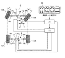
図1は、実施例1のステアリング装置の全体構成図である。
実施例1のステアリング装置は、前輪ステアリング装置Aと、後輪ステアリング装置Bと、操舵モード設定スイッチ(操舵モード設定手段)20と、コントロールユニット(転舵制御手段)21と、アクチュエータドライバ22と、を備えている。
First, the configuration will be described.
FIG. 1 is an overall configuration diagram of the steering apparatus according to the first embodiment.
The steering device of the first embodiment includes a front wheel steering device A, a rear wheel steering device B, a steering mode setting switch (steering mode setting means) 20, a control unit (steering control means) 21, an
[前輪ステアリング装置]
図2は、前輪ステアリング装置Aの構成図である。
ハンドル1が連結されたコラムシャフト上には、操舵角、操舵速度の検出手段である操舵角センサ(操舵状態検出手段)2fが配置されている。
[Front wheel steering device]
FIG. 2 is a configuration diagram of the front wheel steering apparatus A.
On a column shaft to which the handle 1 is connected, a steering angle sensor (steering state detecting means) 2f that is a means for detecting a steering angle and a steering speed is disposed.
ハンドル1の回転トルクは操舵力アシストモータ15fで増幅され、第1交差軸歯車(転舵手段)3を介して車幅方向に配されたステアリングシャフト4fRに伝達されるとともに、ステアリングシャフト4fRの回転方向を正逆転方向で切り替える正逆転切替機構(正逆転切替手段)5fを介してステアリングシャフト4fRに伝達される。操舵力アシストモータ15fと第1交差軸歯車3により、転舵手段が構成される。
The rotational torque of the steering wheel 1 is amplified by the steering
左右のステアリングシャフト4fR,4fLに伝達された回転トルクは、それぞれ等速ジョイント6fR,6fLを介して第2交差軸歯車7fR,7fLに伝達され、非円形歯車列からなる車輪操向歯車8fR,8fLを駆動することにより、左右のナックル9fR,9fLが回転し、車輪10fR,10fLが操向する。 The rotational torque transmitted to the left and right steering shafts 4fR, 4fL is transmitted to the second cross shaft gears 7fR, 7fL via the constant velocity joints 6fR, 6fL, respectively, and the wheel steering gears 8fR, 8fL comprising non-circular gear trains are transmitted. , The left and right knuckles 9fR and 9fL rotate, and the wheels 10fR and 10fL are steered.
車輪10fR,10fLには、駆動モータ14fR,14fLのモータ軸が連結されている。第2交差軸歯車7fR,7fLは、サスペンションサポート11fR,11fLとアッパアーム12fR,12fLにより車体に支持されている。また、駆動モータ14fR,14fLは、ロアアーム13fR,13fLにより車体に支持されている。 The motor shafts of the drive motors 14fR and 14fL are connected to the wheels 10fR and 10fL. The second cross shaft gears 7fR, 7fL are supported on the vehicle body by suspension supports 11fR, 11fL and upper arms 12fR, 12fL. The drive motors 14fR and 14fL are supported on the vehicle body by the lower arms 13fR and 13fL.
[後輪ステアリング装置]
図3は、後輪ステアリング装置Bの構成図である。このステアリング装置は、転舵モータ(転舵手段)15rにより駆動される。転舵モータ15rには、転舵モータ15rの回転角を検出するモータ角度センサ2rが付設されている。
[Rear wheel steering device]
FIG. 3 is a configuration diagram of the rear wheel steering device B. This steering device is driven by a steering motor (steering means) 15r. The steered
他の構成は図2と同様であるが、図2における記号の添え字fをrに変更し、区別してある。 Other configurations are the same as those in FIG. 2, except that the symbol suffix f in FIG. 2 is changed to r.
[操舵モード設定スイッチ]
操舵モード設定スイッチ20は、運転者が通常走行、小回り、その場回転あるいは横移動のいずれかを選択するスイッチであり、操舵モード設定スイッチ20から出力されるモード選択信号は、コントロールユニット21へ出力される。
[Steering mode setting switch]
The steering mode setting switch 20 is a switch for the driver to select normal driving, small turn, on-site rotation or lateral movement, and the mode selection signal output from the steering mode setting switch 20 is output to the
[コントロールユニット]
コントロールユニット21は、操舵角センサ2f、モータ角度センサ2r、操舵モード設定スイッチ20からのモード選択信号、車速等の走行状態に応じて、目標アシスト量、左右輪の目標転舵方向、目標後輪転舵量をそれぞれ算出し、アクチュエータドライバ22へ出力する。
[control unit]
The
アクチュエータドライバ22は、目標アシスト量に応じて操舵力アシストモータ15fを駆動し、運転者の操舵をアシストする。また、左右輪の目標転舵方向に応じて正逆転切替機構5f,5rを切り替える。また、目標後輪転舵量に応じて転舵モータ15rを駆動する。
The
[正逆転切替機構]
図4(a)は、実施例1の正逆転切替機構5fの構成図である。なお、正逆転切替機構5rも同一構造であるため、説明を省略する。
実施例1の正逆転切替機構5fには、ダブルピニオン式遊星歯車が用いられており、サンギヤ51が右側のステアリングシャフト4fRに連結され、キャリア52が左側のステアリングシャフト4fLに連結されている。サンギヤ51とリングギヤ53の歯数比は、0.5に設定されている。なお、これらの結合は左右入れ替えてもよい。
[Forward / reverse switching mechanism]
FIG. 4A is a configuration diagram of the forward /
In the forward /
リングギヤ53は、電磁式ツーウェイクラッチからなるロック機構54によりケース(ハウジング)57に断接される。サンギヤ軸とキャリア軸すなわち左右のステアリングシャフト4fR,4fLは、電磁式ツーウェイクラッチからなる一体回転クラッチ55により断接される。
The
図4(b)は、ロック機構54の構成を示す。リングギヤ53の外周が内輪転動面54aになっており、外輪はケース57に固定され、その転動面54bは正多角形となっており、カム面を形成している。内輪転動面54aと外輪転動面54bの間には複数個のローラ54cが、各カム面上にばね54gと保持器54dにより等間隔に保持されている。
FIG. 4B shows the configuration of the
図4(a)に示した電磁石56の非通電時、保持器54dはフリーとなり、リングギヤ53の回転に保持器54dが連れ周り、カム面とローラ54cとの間の隙間がなくなり、リングギヤ53の回転はロックされる。左右いずれの方向の回転もロックすることができる。一方、通電時には電磁石56によって、保持器54dに連結されたアーマチュア54eがケース57に固定された外輪プレート54fに吸着され、保持器54dが中央位置で保持されるため、カム面とローラ54cとの間には隙間があり、リングギヤ53はどちらの方向にも自由に回転することができる。
When the
図4(c)は、一体回転クラッチ55の構成を示す。外輪55bがキャリア52に装着されている。内輪はサンギヤ51に連結されたステアリングシャフト4Rに装着されており、その転動面55aは正多角形でカム面を形成し、その各カム面上にローラ55cが保持器55dにより等間隔に保持されている。
FIG. 4C shows the configuration of the integral rotation clutch 55. An
図4(a)に示した電磁石56が非通電時、内輪カム面55aに対してローラ55cは、スイッチばね55gにより中立位置に保持されるため、内輪は空転する。一方、通電時には電磁石56によって、保持器55dに連結されたアーマチュア55eがキャリアに固定されたロータ55fに吸着され、内輪の回転によりカム面とローラ55cとの間の隙間がなくなり、左右のステアリングシャフト4fR,4fLは、一体回転する。
When the
次に、作用を説明する。
[その場回転、横移動モード]
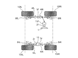
運転者が操舵モード設定スイッチ20により図5に示すその場回転あるいは図6に示す横移動を選択した場合、コントロールユニット21の指令により、アクチュエータドライバ22が前後輪の正逆転切替機構5f、5rと前輪の操舵力アシストモータ15fと後輪の転舵モータ15rの出力制御を行い、自動的の所定の角度まで車輪を操向する。なお、操舵モード設定スイッチ20はデフォルトで通常操舵モードとなるようにしておく。すなわち、エンジンスタート時は常に通常操舵モードとし、車輪が小回り、その場回転、横移動のまま放置されている場合には中立状態に戻す。
Next, the operation will be described.
[Spot rotation, lateral movement mode]
When the driver selects the in-situ rotation shown in FIG. 5 or the lateral movement shown in FIG. 6 by the steering mode setting switch 20, the
[小回りモード]
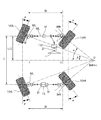
運転者が図7に示す小回りモードを選択した場合には、後輪切れ角が前輪切れ角と大きさが同じで逆位相となるように後輪の転舵モータ15rを出力制御する。
[Turning mode]
When the driver selects the small turning mode shown in FIG. 7, the output control of the rear
[通常操舵モード]
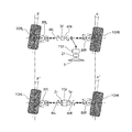
通常操舵モードでは、操舵角センサ2fにより検出される操舵角度と操舵速度および車速から前輪の操舵力アシストモータ15fを最適に制御する。また、操舵角度と操舵速度および車速に応じて後輪の切れ角を前輪と同位相方向にわずかに転舵することにより安定性のある操縦性を得、あるいは逆位相方向にわずかに転舵することによりアンダーステアを少なくすることもできる。図8は、後輪を前輪と同位相でわずかに操舵した例である。
[Normal steering mode]
In the normal steering mode, the front wheel steering force assist
[車輪走行歯車の特性]
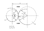
図9は、非円形歯車列からなる車輪走行歯車8fR,8fLのピッチ曲線を示す。第2交差軸歯車7fR,7fLのピッチ曲線は、中立点から外輪駆動側では比が一定の円弧となっており、内輪駆動側では前記外輪駆動側ピッチ曲線で決まる外輪切れ角βに対して所定の切れ角α0までは下記の式(1)
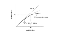
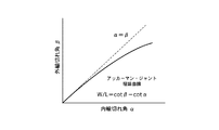
W/L=cotβ-cotα …(1)
すなわちアッカーマン・ジャントの式を満たし、それ以上の切れ角に対しては、下記の式(2)を満たすピッチ曲線からなっている。
2W/L=cotβ-cotα …(2)
ここで、Lは前後輪の車軸間距離を、Wは左右キングピン間距離を表す。
[Characteristics of wheel running gear]
FIG. 9 shows pitch curves of the wheel travel gears 8fR and 8fL made of a non-circular gear train. The pitch curve of the second cross shaft gears 7fR and 7fL is a circular arc with a constant ratio from the neutral point to the outer ring drive side, and the inner ring drive side is predetermined with respect to the outer ring break angle β determined by the outer ring drive side pitch curve. Up to the cutting angle α 0 of the following formula (1)
W / L = cotβ-cotα (1)
In other words, the pitch angle curve satisfies the following formula (2) for cutting angles exceeding the Ackerman-Jant formula.
2W / L = cotβ-cotα (2)
Here, L represents the distance between the axles of the front and rear wheels, and W represents the distance between the left and right king pins.
図中、rii,roiは内輪駆動側の入出力ギヤのピッチ径を表し、rio,rooは外輪駆動側のピッチ径を表し、これらの和は車輪操向歯車の軸間距離に等しい。 In the figure, r ii and roi represent the pitch diameter of the input / output gear on the inner ring drive side , r io and roo represent the pitch diameter on the outer ring drive side, and the sum of these represents the inter-axis distance of the wheel steering gear. equal.
中立点から外輪駆動側では比が一定の円弧となっており、内輪駆動側では前記外輪駆動側ピッチ曲線で決まる外輪切れ角βに対して所定の切れ角α0まではアッカーマン・ジャントの式(1)を満たし、それ以上の切れ角に対しては式(2)を満たすピッチ曲線からなっている。 On the outer ring drive side from the neutral point, the ratio is a constant arc, and on the inner ring drive side, the Ackermann-Jantt equation (up to a predetermined cut angle α 0 with respect to the outer ring cut angle β determined by the outer wheel drive side pitch curve ( It consists of a pitch curve that satisfies formula (2) for angle of cuts that satisfy 1) and beyond.
ここに、Lは前後輪の車軸間距離を、Wは左右キングピン間距離を表す。図中、rii,roiは内輪駆動側の入出力ギヤのピッチ径を表し、rio,rooは外輪駆動側のピッチ径を表し、これらの和は車輪操向歯車の軸間距離に等しい。
Here, L represents the distance between the axles of the front and rear wheels, and W represents the distance between the left and right king pins. In the figure, r ii and roi represent the pitch diameter of the input / output gear on the inner ring drive side , r io and roo represent the pitch diameter on the outer ring drive side, and the sum of these represents the inter-axis distance of the wheel steering gear. equal.
図10に示すように、内外輪の切れ角α,βの関係を示す所定の角度α0,β0までは通常操舵モードで使用し、それ以上の領域は小回りモードで使用する。 As shown in FIG. 10, the normal steering mode is used up to predetermined angles α 0 and β 0 indicating the relationship between the turning angles α and β of the inner and outer wheels, and the area beyond that is used in the small turning mode.
図11,12は、アッカーマン・ジャントの式の操舵機構の原理図である。通常走行時の2輪操舵モードでは、内外輪の切れ角α,βはこの関係を満たし、旋回中心は後輪車軸の延長線上に位置する。 FIGS. 11 and 12 are principle diagrams of the steering mechanism of the Ackerman-Jant type. In the two-wheel steering mode during normal running, the turning angles α and β of the inner and outer wheels satisfy this relationship, and the turning center is located on the extension line of the rear wheel axle.
なお、小回りモード時の内外輪の切れ角の関係式(式(2))の原理は、図7に示したように、
OE/CE=cotα
OF/DF=cotβ
∴ 2W/L=cotβ-cotα
The principle of the relational expression (formula (2)) of the turning angle of the inner and outer rings in the small turning mode is as shown in FIG.
OE / CE = cotα
OF / DF = cotβ
∴ 2W / L = cotβ-cotα
[従来技術の問題点]
特開平4−262971号公報に記載の操舵装置では、タイロッド長さ、左右タイロッド間距離あるいは車輪とナックルアームの成す角を変化させるアクチュエータを備えたリンク機構を要するため、アクチュエータの制御が複雑になるという問題があった。さらに、通常のリンク機構を用いているため、実施例1に示した左右輪逆位相操舵(前後輪逆ハの字)によるその場回転や前後輪を完全に90°転舵させる横移動は不可能である。
[Problems of conventional technology]
The steering device described in Japanese Patent Laid-Open No. 4-262971 requires a link mechanism including an actuator that changes the tie rod length, the distance between the left and right tie rods, or the angle formed by the wheel and the knuckle arm, so that the control of the actuator is complicated. There was a problem. In addition, since a normal link mechanism is used, in-situ rotation and lateral movement that completely steers the front and rear wheels by 90 ° due to the left-right wheel reverse phase steering (front-rear wheel reverse C-shape) shown in the first embodiment are not allowed. Is possible.
一方、各車輪に設けたモータで操舵モードに合わせて直接車輪を操舵する方法も知られているが、各車輪に車輪操舵装置が必要になり、構造が複雑になるばかりでなく、各輪の同期を取った複雑な制御も必要になるという問題があった。さらに、各車輪のステアリングシステムが機械的に連結されていないため、システムがフェールしたとき運転者が車輪を操舵できなくなり、安全上も問題があり、そのフェールセーフため非常な高価となる問題があった。 On the other hand, a method of directly steering a wheel according to a steering mode with a motor provided on each wheel is also known, but each wheel requires a wheel steering device, which not only makes the structure complicated, but also There was a problem that complicated control with synchronization was required. Furthermore, since the steering system of each wheel is not mechanically connected, when the system fails, the driver cannot steer the wheel, which is a safety problem. It was.
[実施例1の操舵作用]
これに対し、実施例1のステアリング装置では、非円形歯車列からなる車輪走行歯車8fR,8fLのピッチ曲線を内外輪の切れ角が所定の関係(所定の切れ角α0までは式(1)、それ以上の角度では式(2))を満たすように設定し、後輪を転舵可能としたため、通常の2輪操舵や高速走行時の前後輪同位相操舵(平行移動)、低速時の大舵角前後輪逆位相操舵(小回り)が可能となるだけでなく、ステアリングシャフトの正逆転切換機構5f,5rを備えるため、左右輪の逆位相操舵が可能となり、前後輪逆ハの字によるその場回転や完全横移動も実現できる。
[Steering Action of Example 1]
In contrast, in the steering apparatus of the first embodiment, the wheel running gear 8fR made of a non-circular gear train until a bending angle alpha 0 turn angle of the inner outer rings predetermined relationship (a predetermined pitch curve of 8fL formula (1) Since the rear wheels can be steered by setting the angle to be larger than that, the rear wheels can be steered. Therefore, normal two-wheel steering, front-rear wheel in-phase steering (parallel movement) at high speed, Not only can large steering angle front / rear wheel reverse phase steering (small turning) be possible, but also equipped with steering shaft forward /
これらさまざまな操舵モードは、ハンドル1の操舵角度や操舵速度および車速に対応して、前輪の操舵力アシストモータ15fと後輪の転舵モータ15rの最適な作動量が算出され、それに基づいて各モータを制御することで実行される。
In these various steering modes, the optimum operation amounts of the steering assist
また、実施例1では、正逆転切替機構5f,5rにはダブルピニオン式遊星歯車を用い、一方の車輪につながるステアリングシャフトとサンギヤ51を連結し、他の車輪につながるステアリングシャフトをキャリア52に連結し、リングギヤ53をケース57に断接するロック機構54とサンギヤ軸とキャリア軸を断接する一体回転クラッチ55で構成した。
In the first embodiment, the forward /
ダブルピニオン式遊星歯車はサンギヤ51とリングギヤ53の歯数比を0.5とすることで、サンギヤ入力、キャリア出力、リングギヤ固定の条件で運転すれば、同じ大きさの回転角で方向が逆の回転を取り出すことができる。図1から図3に示したステアリング機構では、正逆転切換機構5f,5rを逆転モードで作動させたとき、左右輪は同位相で操向し、一体回転モードで作動させると逆位相で操向する。すなわち、通常の2輪操舵や高速走行時の前後輪同位相操舵(平行移動)や低速時の大舵角前後輪逆位相操舵(小回り)では、正逆転切換機構5f,5rを逆転モードで、前後輪逆ハの字によるその場回転や完全横移動操舵では正逆転切換機構5f,5rを一体回転モードで作動させる。
Double pinion planetary gears have a gear ratio of 0.5 to 0.5 for the
実施例1の正逆転切替機構5f,5rでは、ロック機構54は非通電時にロックし通電時に回転可能とし、一方、一体回転クラッチ55は非通電時に回転可能とし、通電時にトルク伝達するようにしたことにより、非通電時に通常の2輪操舵が可能になり、通常操舵モードは正逆転切替機構5f,5rのシステム異常の影響を受けずに作動することができる。
In the forward /
また、ハンドル1から車輪走行歯車8fR,8fLまで機械的に連結した構造としたため、ステアリングシステムの異常時にも運転者が直接車輪を操舵することができ、複雑な機構や制御を用いることなくフェールセーフ機能を持たせることができる。 In addition, since the structure is mechanically connected from the steering wheel 1 to the wheel running gears 8fR, 8fL, the driver can directly steer the wheel even when the steering system is abnormal, and it is fail-safe without using complicated mechanisms and controls. Can have a function.
さらに、ロック機構54と一体回転クラッチ55の電磁石56を共通としたことにより、システムの簡素化を図るとともに、ロック機構54と一体回転クラッチ55が同時に締結することを防止するインターロック機構を持たせることができる。
In addition, since the
次に、効果を説明する。
実施例1のステアリング装置にあっては、以下に列挙する効果が得られる。
Next, the effect will be described.
In the steering device of the first embodiment, the following effects can be obtained.
(1) 前後輪の左右車輪間にそれぞれ配置され、軸心回りに回転可能なステアリングシャフト4f,4rと、車輪のナックル回転軸に設けられた車輪操向歯車8f,8rと、ステアリングシャフト4f,4rの回転を車輪操向歯車8f,8rに伝達する第2交差軸歯車7f,7rと、運転者の操舵に応じて前輪側のステアリングシャフト4fを転舵させる操舵力アシストモータ15fおよび第1交差軸歯車3と、運転者の操舵に応じて後輪側のステアリングシャフト4rを転舵させる転舵モータ15rと、ステアリングシャフト4f,4rを左右2分割した間に介装され、分割された左右ステアリングシャフト(4fR,4fL),(4rR,4rL)の回転方向を正逆方向で切り替える正逆転切替機構5f,5rと、を備える。よって、通常の2輪操舵や高速走行時の前後輪同位相操舵、低速時の大舵角前後輪逆位相操舵(小回り)が可能となるだけでなく、左右輪逆位相操舵(前後輪逆ハの字)によるその場回転や全車輪を90°とする完全横移動が可能であり、アクチュエータの複雑な制御を用いることなく、さまざまな操舵モードを実現できる。
(1) Steering shafts 4f and 4r that are respectively arranged between the left and right wheels of the front and rear wheels and can rotate around the shaft center, wheel steering gears 8f and 8r provided on the knuckle rotating shaft of the wheel, and the steering shaft 4f, Second cross shaft gears 7f, 7r that transmit the rotation of 4r to wheel steering gears 8f, 8r, steering force assist
(2) 正逆転切替機構5f,5rをダブルピニオン式の遊星歯車とし、この遊星歯車のリングギヤ53をケース57に対して断接するロック機構54と、サンギヤ51とキャリア52を断接する一体回転クラッチ55と、を備え、ロック機構54および一体回転クラッチ55をそれぞれ電磁式ツーウェイクラッチで構成し、左右ステアリングシャフトの一方をサンギヤ51に連結し、他方をキャリア52に連結した。よって、シンプルな構成で正逆転切替手段を構成できる。
(2) The forward /
(3) サンギヤ51とリングギヤ53の歯数比を、0.5に設定したため、左右同じ大きさの回転角で方向が逆の回転を取り出すことができ、左右輪の切れ角を同一とすることができる。
(3) Since the gear ratio of the
(4) ロック機構54は、非通電時にリングギヤ53をケース57に固定するとともに、通電時にロック解除し、一体回転クラッチ55は、非通電時にサンギヤ51とキャリア52の締結を解放するとともに、通電時に締結する。よって、非通電時に通常の2輪操舵が可能となり、通常操舵モードは正逆転切替機構5f,5rのシステム異常の影響を受けずに作動することができる。また、ハンドル1から車輪操向歯車(8fR,8fL)まで機械的に連結した構成としたため、ステアリングシステムの異常時にも運転者が直接車輪を操舵することができ、複雑な機構や制御を用いることなくフェールセーフ機能を持たせることができる。
(4) The
(5) ロック機構54と一体回転クラッチ55は、1つの電磁石56を共用するため、システムの簡素化を図ることができるとともに、ロック機構54と一体回転クラッチ55とが同時に締結するのを防止するインターロック機構を持たせることができる。
(5) Since the
(6) 車輪操向歯車(8fR,8fL),(8rR,8rL)は、旋回内外輪の切れ角の関係を、所定の切れ角α0まではアッカーマン・ジャントの式(1)を満たし、それ以上では式(2)を満たすように設定された非円形歯車列である。よって、小舵角時には前後輪共に横滑りのないアッカーマンステアリングを実現できる。また、大舵角時には旋回中心が前輪車軸と後輪車軸の中間線上に位置する最小の回転半径を得ることができ、小回り性能を大幅に向上させることができる。 (6) the wheel steering gear (8FR, 8FL), satisfies the (8RR, 8RL) is the relationship between the turning angle of the turning inner and outer, until a predetermined cutting angle alpha 0 of Ackermann Jeantaud formula (1), it In the above, the non-circular gear train is set so as to satisfy the expression (2). Therefore, it is possible to realize Ackermann steering with no side slip on the front and rear wheels at a small steering angle. Further, at the time of a large steering angle, it is possible to obtain the minimum turning radius in which the turning center is located on the middle line between the front wheel axle and the rear wheel axle, and it is possible to greatly improve the small turning performance.
(7) 車両の操舵モードを設定する操舵モード設定スイッチ20と、ハンドル1の操舵角度と操舵速度を検出する操舵角センサ2fと、設定された操舵モードと検出された操舵角度および操舵速度と車速とに応じて、操舵力アシストモータ15fと転舵モータ15rを駆動制御するコントロールユニット21と、を備える。よって、設定された操舵モードに基づき、ハンドル1の操舵角や操舵角度および車速に対応した最適な前後輪転舵量を設定できる。
(7) A steering mode setting switch 20 for setting the steering mode of the vehicle, a
実施例2は、正逆転切替機構の一体回転クラッチをドグクラッチ(噛み合いクラッチ)とした例である。
図13は、実施例2の正逆転切替機構の構成図である。なお、図4に示した実施例1と同一の構成には、同一符号を付して説明を省略する。
The second embodiment is an example in which the integral rotation clutch of the forward / reverse switching mechanism is a dog clutch (meshing clutch).
FIG. 13 is a configuration diagram of a forward / reverse switching mechanism according to the second embodiment. In addition, the same code | symbol is attached | subjected to the structure same as Example 1 shown in FIG. 4, and description is abbreviate | omitted.
実施例2の正逆転切替機構55は、サンギヤ51に連結されたステアリングシャフト4fR上に、側面に突起55k(図13(b))を持ったクラッチギヤ55hがスプライン等で軸方向移動可能に装着されている。一方、キャリアプレート55iには前記突起55kに嵌合する溝55m(図13(c))が設けられている。アクチュエータ58とレバー55jによりクラッチギヤ55hがキャリアプレート55iに断接される構造となっている。
The forward /
この一体回転クラッチ55の締結状態で、左右輪の中立位置およびトー調整をしておくことにより、クラッチの断接による中立位置のずれやトーの狂いが生じることがなく、操舵性能の悪化やタイヤの偏磨耗を防止することができる。 By adjusting the neutral position and toe adjustment of the left and right wheels in the engaged state of the integral rotary clutch 55, there is no shift in the neutral position due to the clutch connection or disconnection, or a toe error occurs. It is possible to prevent uneven wear.
次に、効果を説明する。
実施例2のステアリング装置にあっては、実施例1の効果(1)〜(7)に加え、以下の効果が得られる。
Next, the effect will be described.
In the steering device of the second embodiment, the following effects can be obtained in addition to the effects (1) to (7) of the first embodiment.
(8) 一体回転クラッチ55を、サンギヤ側ステアリングシャフト(4fR)とキャリア側ステアリングシャフト(4fL)とが決まった位相(180°)で噛み合うドグクラッチとしたことにより、左右輪の位相のずれを完全に除去することができる。 (8) The integral rotation clutch 55 is a dog clutch in which the sun gear side steering shaft (4fR) and the carrier side steering shaft (4fL) mesh with each other at a fixed phase (180 °). Can be removed.
(他の実施例)
以上、本発明を実施するための最良の形態を、実施例に基づいて説明したが、本発明の具体的な構成は、実施例1,2に限定されるものではなく、例えば、本発明のステアリング装置は、電動車両以外の車両にも適用できる。
(Other examples)
The best mode for carrying out the present invention has been described based on the embodiments. However, the specific configuration of the present invention is not limited to the first and second embodiments. The steering device can also be applied to vehicles other than electric vehicles.
また、実施例1,2では、ハンドルと前輪側のステアリングシャフトとが第1交差軸歯車を介して機械的に連結されたステアリング装置を示したが、本発明は、ハンドルとステアリングシャフトとが機械的に切り離された、いわゆるステア・バイ・ワイヤシステムにも用いることができる。 In the first and second embodiments, the steering device is shown in which the steering wheel and the steering wheel on the front wheel side are mechanically coupled via the first cross shaft gear. However, in the present invention, the steering wheel and the steering shaft are mechanically connected. It can also be used in a so-called steer-by-wire system that is disconnected in an automatic manner.
A 前輪ステアリング装置
B 後輪ステアリング装置
1 ハンドル
3 第1交差軸歯車
4fR,4fL ステアリングシャフト
5f,5r 正逆転切替機構
7fR,7fL 第2交差軸歯車
8fR,8fL 車輪走行歯車
9fR,9fL ナックル
10fR,10fL 車輪
11fR,11fL サスペンションサポート
12fR,12fL アッパアーム
13fR,13fL ロアアーム
14fR,14fL 駆動モータ
15f 操舵力アシストモータ
20 操舵モード設定スイッチ
21 コントロールユニット
22 アクチュエータドライバ
51 サンギヤ
52 キャリア
53 リングギヤ
54 ロック機構
55 一体回転クラッチ
56 電磁石
57 ケース
58 アクチュエータ
A Front wheel steering device B Rear wheel steering device 1
4fR, 4fL Steering shaft
5f, 5r forward / reverse switching mechanism
7fR, 7fL Second cross shaft gear
8fR, 8fL Wheel running gear
9fR, 9fL knuckle
10fR, 10fL wheel
11fR, 11fL suspension support
12fR, 12fL Upper arm
13fR, 13fL Lower arm
14fR, 14fL drive motor
15f Steering force assist motor
20 Steering mode setting switch
21 Control unit
22 Actuator driver
51 Sungear
52 Career
53 Ring gear
54 Locking mechanism
55 Integrated rotating clutch
56 Electromagnet
57 cases
58 Actuator
Claims (7)
車輪のナックル回転軸に設けられた車輪操向歯車と、
前記ステアリングシャフトの回転を前記車輪操向歯車に伝達する交差軸歯車と、
運転者の操舵に応じて前後ステアリングシャフトをそれぞれ回転させる転舵手段と、
前記ステアリングシャフトを左右2分割した間に介装され、分割された左右ステアリングシャフトの回転方向を正逆方向で切り替える正逆転切替手段と、
を備え、
前記正逆転切替手段をダブルピニオン式の遊星歯車とし、
この遊星歯車のリングギヤをハウジングに対して断接するロック機構と、サンギヤとキャリアを断接する一体回転クラッチと、を備え、
前記ロック機構および前記一体回転クラッチをそれぞれ電磁式ツーウェイクラッチで構成し、
前記分割された左右ステアリングシャフトの一方を前記サンギヤに連結し、他方を前記キャリアに連結したことを特徴とするステアリング装置。 A steering shaft that is arranged between the left and right wheels of the front and rear wheels and is rotatable about an axis;
A wheel steering gear provided on the knuckle rotation shaft of the wheel;
A cross shaft gear for transmitting rotation of the steering shaft to the wheel steering gear;
Steering means for rotating the front and rear steering shafts according to the steering of the driver,
Forward / reverse switching means that is interposed between the left and right divided steering shafts and switches the rotation direction of the divided left and right steering shafts in forward and reverse directions;
Equipped with a,
The forward / reverse switching means is a double pinion planetary gear,
A lock mechanism for connecting and disconnecting the ring gear of the planetary gear to the housing, and an integral rotary clutch for connecting and disconnecting the sun gear and the carrier,
The lock mechanism and the integral rotary clutch are each constituted by an electromagnetic two-way clutch,
One of the divided left and right steering shafts is connected to the sun gear, and the other is connected to the carrier .
前記サンギヤと前記リングギヤの歯数比を、0.5に設定したことを特徴とするステアリング装置。 The steering apparatus according to claim 1, wherein
A steering device, wherein a gear ratio of the sun gear and the ring gear is set to 0.5.
前記ロック機構は、非通電時に前記リングギヤを前記ハウジングに固定するとともに、通電時にロック解除し、
前記一体回転クラッチは、非通電時に前記サンギヤと前記キャリアの締結を解放するとともに、通電時に締結することを特徴とするステアリング装置。 The steering apparatus according to claim 1 or 2,
The lock mechanism fixes the ring gear to the housing when not energized, and unlocks when energized,
The integral rotation clutch releases the engagement between the sun gear and the carrier when not energized and is engaged when energized.
前記ロック機構と前記一体回転クラッチは、1つの電磁石を共用することを特徴とするステアリング装置。 In claims 1 steering apparatus according to any one of claims 3,
The steering device according to claim 1, wherein the lock mechanism and the integral rotary clutch share one electromagnet.
前記一体回転クラッチを、前記ステアリングシャフトの左右があらかじめ決められた位相で噛み合うドグクラッチとしたことを特徴とするステアリング装置。 The steering device according to any one of claims 1 to 4,
The steering device according to claim 1, wherein the integral rotation clutch is a dog clutch in which the left and right sides of the steering shaft mesh with each other at a predetermined phase.
前記車輪操向歯車は、旋回内外輪の切れ角を所定の関係に保つ非円形歯車列であることを特徴とするステアリング装置。 The steering device according to any one of claims 1 to 5,
The steering apparatus according to claim 1, wherein the wheel steering gear is a non-circular gear train that maintains a predetermined relationship between the turning angles of the turning inner and outer wheels.
車両の操舵モードを設定する操舵モード設定手段と、
ハンドルの操舵角度と操舵速度を検出する操舵状態検出手段と、
設定された操舵モードと検出された操舵角度および操舵速度と車速とに応じて、前後輪の転舵手段を駆動制御する転舵制御手段と、
を備えることを特徴とするステアリング装置。 The steering apparatus according to any one of claims 1 to 6,
Steering mode setting means for setting the steering mode of the vehicle;
Steering state detection means for detecting the steering angle and steering speed of the steering wheel;
Steering control means for driving and controlling the steering means for the front and rear wheels according to the set steering mode, the detected steering angle, the steering speed, and the vehicle speed;
A steering apparatus comprising:
Priority Applications (1)
| Application Number | Priority Date | Filing Date | Title |
|---|---|---|---|
| JP2005203455A JP4635754B2 (en) | 2005-07-12 | 2005-07-12 | Steering device |
Applications Claiming Priority (1)
| Application Number | Priority Date | Filing Date | Title |
|---|---|---|---|
| JP2005203455A JP4635754B2 (en) | 2005-07-12 | 2005-07-12 | Steering device |
Publications (2)
| Publication Number | Publication Date |
|---|---|
| JP2007022159A JP2007022159A (en) | 2007-02-01 |
| JP4635754B2 true JP4635754B2 (en) | 2011-02-23 |
Family
ID=37783506
Family Applications (1)
| Application Number | Title | Priority Date | Filing Date |
|---|---|---|---|
| JP2005203455A Expired - Fee Related JP4635754B2 (en) | 2005-07-12 | 2005-07-12 | Steering device |
Country Status (1)
| Country | Link |
|---|---|
| JP (1) | JP4635754B2 (en) |
Cited By (3)
| Publication number | Priority date | Publication date | Assignee | Title |
|---|---|---|---|---|
| WO2015072375A1 (en) | 2013-11-14 | 2015-05-21 | Ntn株式会社 | Vehicle |
| WO2015076253A1 (en) | 2013-11-20 | 2015-05-28 | Ntn株式会社 | Vehicle |
| WO2015146803A1 (en) * | 2014-03-25 | 2015-10-01 | Ntn株式会社 | Driving mode switch control method and vehicle |
Families Citing this family (18)
| Publication number | Priority date | Publication date | Assignee | Title |
|---|---|---|---|---|
| JP5282485B2 (en) * | 2008-08-26 | 2013-09-04 | 日産自動車株式会社 | Steering device and steering wheel steering method |
| JP5428360B2 (en) * | 2009-02-03 | 2014-02-26 | 日産自動車株式会社 | Steering device |
| JP5321225B2 (en) * | 2009-04-24 | 2013-10-23 | 日産自動車株式会社 | Steering device |
| KR101675801B1 (en) * | 2012-02-24 | 2016-11-15 | 한화테크윈 주식회사 | Steering device for vehicle capable of cycle steering |
| JP5919900B2 (en) * | 2012-03-08 | 2016-05-18 | 日産自動車株式会社 | Steering device |
| JP6119309B2 (en) * | 2013-03-04 | 2017-04-26 | 日産自動車株式会社 | Cross shaft gear transmission mechanism and wheel steering device using the same |
| WO2014171389A1 (en) * | 2013-04-18 | 2014-10-23 | Ntn株式会社 | Steering device, vehicle using same steering device, and vehicle equipped with four-wheel steering mechanism |
| JP6382545B2 (en) * | 2013-07-31 | 2018-08-29 | Ntn株式会社 | Steering device and vehicle equipped with the same |
| JP6351944B2 (en) * | 2013-09-26 | 2018-07-04 | Ntn株式会社 | Steering device |
| JP2015071363A (en) * | 2013-10-03 | 2015-04-16 | Ntn株式会社 | Steering device |
| JP2015090170A (en) * | 2013-11-05 | 2015-05-11 | Ntn株式会社 | Brake unit, vehicle loading brake unit, and method for loading brake unit to vehicle |
| JP6437189B2 (en) * | 2013-11-08 | 2018-12-12 | Ntn株式会社 | Steering device and steering device system |
| JP2015098262A (en) * | 2013-11-19 | 2015-05-28 | Ntn株式会社 | Drive steering module, and vehicle equipped with drive steering module |
| WO2016039312A1 (en) * | 2014-09-11 | 2016-03-17 | Ntn株式会社 | Steering device and vehicle running mode switching method |
| JP2017007575A (en) * | 2015-06-24 | 2017-01-12 | Ntn株式会社 | Steering device, and vehicle having steering device |
| KR102265660B1 (en) * | 2019-11-21 | 2021-06-17 | 주식회사 케이에스티일렉트릭 | Method and Apparatus for Controlling Pivot Vehicle |
| JP7686547B2 (en) * | 2021-12-07 | 2025-06-02 | 三菱マヒンドラ農機株式会社 | Riding rice transplanter |
| CN119953453B (en) * | 2025-04-09 | 2025-07-15 | 吉林大学 | A dual-mode steering coordinated control method and system for a five-axis heavy-load AGV |
Family Cites Families (11)
| Publication number | Priority date | Publication date | Assignee | Title |
|---|---|---|---|---|
| JPS5815258Y2 (en) * | 1977-09-22 | 1983-03-28 | 小松フオ−クリフト株式会社 | steering differential mechanism |
| JPS5992262A (en) * | 1982-11-19 | 1984-05-28 | Agency Of Ind Science & Technol | All-direction movable vehicle |
| JPS60193778A (en) * | 1984-03-14 | 1985-10-02 | Nippon Yusoki Co Ltd | Direction switching mechanism for all-direction transfer dolly |
| JPS6231577U (en) * | 1985-08-12 | 1987-02-25 | ||
| JPS6341281A (en) * | 1986-08-05 | 1988-02-22 | Nissan Motor Co Ltd | Actual steering angle control device for vehicle |
| JP2538951B2 (en) * | 1987-11-12 | 1996-10-02 | 日産自動車株式会社 | Vehicle steering method |
| JPH01172066A (en) * | 1987-12-26 | 1989-07-06 | Aisin Aw Co Ltd | Car steering mechanism |
| JP3237872B2 (en) * | 1991-07-24 | 2001-12-10 | 科学技術振興事業団 | Steering mechanism using non-circular gear |
| JPH07280047A (en) * | 1994-04-11 | 1995-10-27 | Jatco Corp | Gear train for automatic transmission |
| JPH11263242A (en) * | 1998-03-18 | 1999-09-28 | Iseki & Co Ltd | Work vehicle steering system |
| JPH11278077A (en) * | 1998-03-30 | 1999-10-12 | Fuji Heavy Ind Ltd | Drive device for four-wheel drive vehicle |
-
2005
- 2005-07-12 JP JP2005203455A patent/JP4635754B2/en not_active Expired - Fee Related
Cited By (6)
| Publication number | Priority date | Publication date | Assignee | Title |
|---|---|---|---|---|
| WO2015072375A1 (en) | 2013-11-14 | 2015-05-21 | Ntn株式会社 | Vehicle |
| US9834249B2 (en) | 2013-11-14 | 2017-12-05 | Ntn Corporation | Vehicle with steering devices for front and rear wheels |
| WO2015076253A1 (en) | 2013-11-20 | 2015-05-28 | Ntn株式会社 | Vehicle |
| US9758190B2 (en) | 2013-11-20 | 2017-09-12 | Ntn Corporation | Vehicle |
| WO2015146803A1 (en) * | 2014-03-25 | 2015-10-01 | Ntn株式会社 | Driving mode switch control method and vehicle |
| JP2015182637A (en) * | 2014-03-25 | 2015-10-22 | Ntn株式会社 | Driving mode switching control method and vehicle |
Also Published As
| Publication number | Publication date |
|---|---|
| JP2007022159A (en) | 2007-02-01 |
Similar Documents
| Publication | Publication Date | Title |
|---|---|---|
| JP4635754B2 (en) | Steering device | |
| JP5919900B2 (en) | Steering device | |
| EP3050780B1 (en) | Steering device | |
| US9919730B2 (en) | Steering device and vehicle including the same | |
| EP3072781B1 (en) | Vehicle | |
| JP2012121391A (en) | Steering device | |
| JP5332446B2 (en) | Suspension with steering device | |
| JP2010058681A (en) | Suspension with steering device | |
| JP4635753B2 (en) | Steering device | |
| JPH01175577A (en) | Rear wheel steering mechanism | |
| JP2010254129A (en) | Steering device | |
| WO2014203574A1 (en) | Steering device | |
| WO2015050190A1 (en) | Steering device | |
| JP7718227B2 (en) | Vehicle control device | |
| JP3109920B2 (en) | Steering gear | |
| JP2016055804A (en) | Steering device and method for changing driving modes of vehicle | |
| JP4930300B2 (en) | Stabilizer control device | |
| WO2016121677A1 (en) | Steering device and vehicle equipped with same | |
| JP2009006876A (en) | Steering device, automobile and rack housing mounting method | |
| JP2560825B2 (en) | Rear wheel steering system for front and rear wheel steering vehicles | |
| JPH0986430A (en) | Vehicle rear wheel steering system | |
| JP2005145254A (en) | Vehicle steering device | |
| JPH04118377A (en) | four-wheel steering device | |
| JPS60154958A (en) | Vehicle four-wheel steering system | |
| JPH0532235U (en) | Four-wheel steering system |
Legal Events
| Date | Code | Title | Description |
|---|---|---|---|
| A621 | Written request for application examination |
Free format text: JAPANESE INTERMEDIATE CODE: A621 Effective date: 20080527 |
|
| A977 | Report on retrieval |
Free format text: JAPANESE INTERMEDIATE CODE: A971007 Effective date: 20100611 |
|
| A131 | Notification of reasons for refusal |
Free format text: JAPANESE INTERMEDIATE CODE: A131 Effective date: 20100817 |
|
| A521 | Request for written amendment filed |
Free format text: JAPANESE INTERMEDIATE CODE: A523 Effective date: 20100831 |
|
| TRDD | Decision of grant or rejection written | ||
| A01 | Written decision to grant a patent or to grant a registration (utility model) |
Free format text: JAPANESE INTERMEDIATE CODE: A01 Effective date: 20101026 |
|
| A01 | Written decision to grant a patent or to grant a registration (utility model) |
Free format text: JAPANESE INTERMEDIATE CODE: A01 |
|
| A61 | First payment of annual fees (during grant procedure) |
Free format text: JAPANESE INTERMEDIATE CODE: A61 Effective date: 20101108 |
|
| FPAY | Renewal fee payment (event date is renewal date of database) |
Free format text: PAYMENT UNTIL: 20131203 Year of fee payment: 3 |
|
| R150 | Certificate of patent or registration of utility model |
Free format text: JAPANESE INTERMEDIATE CODE: R150 |
|
| LAPS | Cancellation because of no payment of annual fees |
