JP4635673B2 - Soft packaging bag spout and fluid food soft packaging bag with the spout attached - Google Patents
Soft packaging bag spout and fluid food soft packaging bag with the spout attached Download PDFInfo
- Publication number
- JP4635673B2 JP4635673B2 JP2005085585A JP2005085585A JP4635673B2 JP 4635673 B2 JP4635673 B2 JP 4635673B2 JP 2005085585 A JP2005085585 A JP 2005085585A JP 2005085585 A JP2005085585 A JP 2005085585A JP 4635673 B2 JP4635673 B2 JP 4635673B2
- Authority
- JP
- Japan
- Prior art keywords
- spout
- packaging bag
- cylinder
- catheter
- flexible packaging
- Prior art date
- Legal status (The legal status is an assumption and is not a legal conclusion. Google has not performed a legal analysis and makes no representation as to the accuracy of the status listed.)
- Expired - Fee Related
Links
Images

Landscapes
- Bag Frames (AREA)
- Medical Preparation Storing Or Oral Administration Devices (AREA)
Description
本発明は、軟包装袋用のスパウトと該スパウトを取り付けた流動食用軟包装袋に関するものであり、特には、ガスバリア性に優れた軟包装袋用のスパウトと該スパウトを取り付
けた流動食用軟包装袋に関する。
TECHNICAL FIELD The present invention relates to a soft packaging bag spout and a fluid food soft packaging bag to which the spout is attached, and in particular, a soft packaging bag spout having excellent gas barrier properties and a liquid food soft packaging to which the spout is attached. Regarding bags.
従来、寝たきりの患者などへの栄養補給の手段の一つに流動食がある。流動食は、使用時に温められ注入用容器に移し代えて投与されている。その際、流動食は細菌に汚染される可能性が生じるため、一定の時間内に使い切らなければならなくなる。この問題点を解決するため、容器に移し代える必要のない、投与バッグ式の流動食用容器、すなわち、直接カテーテルまたはチューブに接合できる軟包装袋が開発されている。 Conventionally, there is a liquid food as one of the means of nutrition supply for bedridden patients and the like. The liquid food is warmed at the time of use and transferred to an infusion container for administration. At that time, the liquid food may be contaminated with bacteria, so it must be used up within a certain time. In order to solve this problem, a liquid food container of an administration bag type that does not need to be transferred to a container, that is, a flexible packaging bag that can be directly joined to a catheter or a tube has been developed.
この軟包装袋は、例えば、図4に示すように、スパウト(210)のスパウトに連通してカテーテルやチューブに直接内挿できるカテーテル接続口(213)を有している。 For example, as shown in FIG. 4, the flexible packaging bag has a catheter connection port (213) that communicates with the spout of the spout (210) and can be directly inserted into a catheter or a tube.
しかしこのカテーテル接続口(213)は、ポリエチレン等のポリオレフィン系樹脂を射出成形して作製されており、しかも、バリア性を有する軟包装袋から突出して取り付けられているため、全体のバリア性能に悪影響を及ぼしている。 However, this catheter connection port (213) is produced by injection molding a polyolefin-based resin such as polyethylene, and is attached so as to protrude from the flexible packaging bag having a barrier property, thus adversely affecting the overall barrier performance. Is exerting.
本発明は、カテーテル接続口を有する流動食用軟包装袋に関する以上のような問題に鑑みてなされたもので、ガスバリア性に優れた軟包装袋用のスパウトと該スパウトを取り付けた流動食用軟包装袋を提供することを課題とする。 The present invention has been made in view of the above-mentioned problems relating to a soft wrapping bag for liquid foods having a catheter connection port. It is an issue to provide.
本発明の請求項1の発明は、中央が中空に成形された貫通孔を有するシール基部と、該シール基部の貫通孔の周壁に接合され、該貫通孔より上側に飛び出した長さは、貫通孔より下側に飛び出した長さより短く飛び出して成形された外側の筒体と、該外側の筒体の内側に該外側の筒体と同心円を描くように該外側の筒体と同じ長さに挿入されたカテーテル接続筒体と、前記外側の筒体の下端縁内側と前記カテーテル接続筒体の下端縁外側とを連接する環状板とからなる注出口と、前記外側の筒体の先端周縁とカテーテル接続筒体の先端周縁とが同一平面上で熱融着される密封蓋とから構成され、前記カテーテル接続筒体は、上方に行くに従い先細る形状であり、且つ前記カテーテル接続筒体の外側には、凸部が形成されていることを特徴とする軟包装袋用スパウトである。 According to the first aspect of the present invention, there is provided a seal base having a through hole formed in the center of the hollow and a peripheral wall of the through hole of the seal base, and a length protruding above the through hole is and an outer cylindrical body which is formed protrudes shorter than the length jumped out below the hole, the same length as the outer cylindrical body so as to draw a tubular body concentric with the outer inside of the outer cylindrical body A spout formed of an inserted catheter connection cylinder, an annular plate connecting the inner side of the lower end edge of the outer cylinder and the outer side of the lower end edge of the catheter connection cylinder, and a peripheral edge of the distal end of the outer cylinder The distal end periphery of the catheter connection cylinder is composed of a sealing lid that is heat-sealed on the same plane, and the catheter connection cylinder has a tapered shape as it goes upward, and the outside of the catheter connection cylinder Is characterized in that a convex part is formed. A spout for flexible packaging bag.
このように請求項1記載の発明によれば、中央が中空に成形された貫通孔を有するシール基部と、該シール基部の貫通孔の周壁に接合され、該貫通孔より上側に飛び出した長さは、貫通孔より下側に飛び出した長さより短く飛び出して成形された外側の筒体と、該外側の筒体の内側に該外側の筒体と同心円を描くように該外側の筒体と同じ長さに挿入されたカテーテル接続筒体と、前記外側の筒体の下端縁内側と前記カテーテル接続筒体の下端縁外側とを連接する環状板とからなる注出口と、前記外側の筒体の先端周縁とカテーテル接続筒体の先端周縁とが同一平面上で熱融着される密封蓋と、から構成されているので、カテーテル接続筒体部分は注出口に内蔵されているので、ガスバリア性は密封蓋により担保されているし、密封蓋を開けてカテーテル接続筒体にカテーテルを挿入するのみで、内容物を取り出すことができる。 As described above, according to the first aspect of the present invention, the seal base having a through hole formed in the center of the hollow, and the length of the seal base that is joined to the peripheral wall of the through hole of the seal base and protrudes upward from the through hole. includes an outer cylindrical body which is formed protrudes shorter than the length jumped out below the through-hole, the same as the outer cylindrical body so as to draw a tubular body concentric with the outer inside of the outer cylindrical body a catheter connection tube body that is inserted into a length, the spout comprising a circular plate which connects the lower edge outer lower edge inside said catheter connection tube body of said outer tubular body, said outer tubular body Since the distal end periphery and the distal end periphery of the catheter connecting cylinder are heat sealed on the same plane, the catheter connecting cylinder part is built in the spout, so the gas barrier property is It is secured by a sealing lid and the sealing lid is opened Only inserting the catheter into the catheter connecting tube body can be taken out the contents.
削除 Delete
また、請求項1記載の発明によれば、前記カテーテル接続筒体は上方に行くに従い先細る形状であるので、カテーテルを注出口に取り付ける際、カテーテルのカテーテル接続筒体への取り付けが容易である。 According to the first aspect of the present invention, since the catheter connecting cylinder is tapered as it goes upward, it is easy to attach the catheter to the catheter connecting cylinder when the catheter is attached to the spout. .
削除 Delete
また、請求項1記載の発明によれば、カテーテル接続筒体の外側には凸部が形成されているので、取り付けたカテーテルがカテーテル接続筒体から外れにくい。 According to the first aspect of the present invention, since the convex portion is formed on the outside of the catheter connection tube, the attached catheter is unlikely to come off from the catheter connection tube.
本発明の請求項2の発明は、請求項1の発明において、前記外側の筒体の上部には、前記密封蓋を剥がした後のカテーテル接続筒体の上端縁を封鎖する密封キャップが取り付けられていることを特徴とする、軟包装袋用スパウトである。 According to a second aspect of the present invention, in the first aspect of the invention, a sealing cap for sealing the upper end edge of the catheter connecting cylinder after the sealing lid is peeled off is attached to the upper part of the outer cylinder. It is the spout for flexible packaging bags characterized by the above-mentioned.
このように請求項2記載の発明によれば、筒体の上部には、カテーテル接続筒体の上端縁を封鎖する密封キャップが取り付けられているので、一度密封蓋を剥がした軟包装袋用スパウトであっても、容易に密封キャップで再封鎖することができる。 According to the invention thus claim 2, wherein, in the upper portion of the cylindrical body, since the sealing cap is mounted to sequester upper edge of the catheter connecting tube body, flexible packaging bag spout once peeled sealing lid Even so, it can be easily resealed with a sealing cap.
本発明の請求項3の発明は、請求項1、2の発明において、前記シール基部の外周には複数のリブが形成されていることを特徴とする、軟包装袋用スパウトである。 A third aspect of the present invention is the soft packaging bag spout according to the first and second aspects, wherein a plurality of ribs are formed on the outer periphery of the seal base.
このように請求項3記載の発明によれば、シール基部の外周には、複数のリブが形成されているので、スパウトを軟包装袋に取り付ける際、熱融着を比較的容易に行うことができる。 Thus, according to the invention described in claim 3, since the plurality of ribs are formed on the outer periphery of the seal base portion, when attaching the spout to the flexible packaging bag, it is possible to relatively easily perform the heat fusion. it can.
本発明の請求項4の発明は、請求項1ないし請求項3のいずれか1項記載の軟包装袋用スパウトを軟包装袋の注出部として取り付けた流動食軟包装袋である。 Invention of Claim 4 of this invention is the liquid food soft packaging bag which attached the spout for soft packaging bags of any one of Claim 1 thru | or 3 as the extraction | pouring part of a soft packaging bag.
このように本発明の軟包装袋用スパウトは、カテーテル接続口を注出口の内部に内蔵した形態をとっているので、密封蓋を開封しない限りはガスバリア性に影響を与えることはない。また、この軟包装袋用スパウトを使用した軟包装袋は、ガスバリア性に優れ、流動食用の軟包装袋として有用である。 Thus, since the spout for soft packaging bags of the present invention has a form in which the catheter connection port is built in the spout, the gas barrier property is not affected unless the sealing lid is opened. Moreover, the soft packaging bag using this spout for soft packaging bags has excellent gas barrier properties and is useful as a soft packaging bag for liquid food.
本発明を一実施形態に基づいて以下に詳細に説明する。
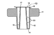
本発明の軟包装袋用スパウト(10)は、例えば、図1に示すように、中央が中空に成形された貫通孔を有するシール基部(11)と、このシール基部(11)の貫通孔の周壁に接合され、該貫通孔より上側に飛び出した長さは、貫通孔より下側に飛び出した長さより短く飛び出して成形された外側の筒体(12)と、この外側の筒体(12)の内側に外側の筒体(12)と同心円を描くように外側の筒体(12)と同じ長さに挿入されたカテーテル接続筒体(13)と、外側の筒体(12)の下端縁内側と、カテーテル接続筒体(13)の下端縁外側を連接する環状板(14)とからなる注出口(15)と、外側の筒体の先端周縁(16)とカテーテル接続筒体(13)の先端周縁(17)とが同一平面上で熱融着される密封蓋(18)と、から構成されている。
The present invention will be described in detail below based on one embodiment.
The spout (10) for a flexible packaging bag according to the present invention includes, for example, as shown in FIG. 1, a seal base (11) having a through hole formed in a hollow center and a through hole of the seal base (11). The outer cylinder (12) which is joined to the peripheral wall and protrudes upward from the through hole is shorter than the length which protrudes downward from the through hole, and the outer cylinder (12). the lower edge of the outer cylindrical member to the inner (12) and the outer cylindrical body so as to draw a concentric circle (12) and inserted into the same length catheter connecting tube body (13), the outer surface of cylindrical body (12) A spout (15) composed of an inner side and an annular plate (14) connecting the outer side of the lower end of the catheter connecting tube (13), a distal end periphery (16) of the outer tube, and the catheter connecting tube (13) A sealing lid (18) to which the tip peripheral edge (17) is heat-sealed on the same plane; It is constructed from.
軟包装袋用スパウト(1)は、一般的には密封蓋(18)を除いて、ポリエチレン、ポリプロピレン等のポリオレフィン系熱可塑性樹脂を射出成形法などの成形方法を用いて容易に作製することができる。 The spout for flexible packaging bags (1) can be easily produced by using a molding method such as an injection molding method such as polyethylene or polypropylene, except for the sealing lid (18). it can.
シール基部(11)は、軟包装袋(20)と熱融着し易いように両端を薄くした船形状に形成されている場合が多い。また、外周には複数のリブ(111)が形成されている。 In many cases, the seal base (11) is formed in a ship shape in which both ends are thin so as to be easily heat-sealed with the flexible packaging bag (20). A plurality of ribs (111) are formed on the outer periphery.
カテーテル接続筒体(13)は、図1に示すように、上方に行くに従い先細る形状に成形しておくことにより、使用時にカテーテル(40)が挿入し易くなる。また、カテーテ
ル接続筒体(13)の外周面に凸部(131)を形成させておくことにより、カテーテル(40)とカテーテル接続筒体(13)の間に抵抗力が増し、カテーテル接続筒体(13)からカテーテル(40)が抜けにくくなる。
As shown in FIG. 1, the catheter connecting cylinder (13) is formed into a tapered shape as it goes upward, so that the catheter (40) can be easily inserted during use. Further, by forming the convex portion (131) on the outer peripheral surface of the catheter connection cylinder (13), the resistance force increases between the catheter (40) and the catheter connection cylinder (13), and the catheter connection cylinder It becomes difficult for the catheter (40) to come off from (13).
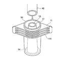
また、外側の筒体(12)の上部には、カテーテル接続筒体(13)の上端縁を封鎖するための密封キャップ(121)を取り付けておくと密封蓋(18)を剥がした後の使用時に密封キャップ(121)で再封鎖できるので有利である。これは、図示のようなカバーキャップを被せるタイプのものがより好ましい。 Moreover, if the sealing cap (121) for sealing the upper end edge of a catheter connection cylinder (13) is attached to the upper part of an outer cylinder (12) , use after peeling a sealing lid (18) Advantageously, it can sometimes be resealed with a sealing cap (121) . This is more preferably of a type that covers a cover cap as shown.
密封蓋(18)は、〔外側〕アルミニウム箔/ポリエチレン〔内側〕、無機化合物蒸着プラスチックフィルム/ポリエチレン、二軸延伸ポリプロピレンフィルム(印刷層)/無機化合物蒸着プラスチックフィルム/ポリエチレン等のガスバリア性に優れ、かつ、外側の筒体(12)の先端周縁(16)とカテーテル接続筒体(13)の先端周縁(17)との熱融着性に優れた複合フィルムが好ましく使用できる。 The sealing lid (18) has excellent gas barrier properties such as [outside] aluminum foil / polyethylene [inside], inorganic compound vapor-deposited plastic film / polyethylene, biaxially stretched polypropylene film (printing layer) / inorganic compound vapor-deposited plastic film / polyethylene, etc. And the composite film excellent in the heat-sealing property of the front-end | tip periphery (16) of an outer cylinder (12) and the front-end | tip periphery (17) of a catheter connection cylinder (13) can be used preferably.
なおここで記した無機化合物蒸着プラスチックフィルムとは、一軸ないし二軸延伸されたポリエチレンテレフタレートフィルム、ナイロンフィルム、ポリオレフィンフィルムなどの延伸フィルム上に、酸化アルミニウムや酸化ケイ素などの無機化合物の薄膜を物理蒸着あるいは化学蒸着などの蒸着法により20〜100nm程度の厚さに設けた蒸着プラスチックフィルムのことをいう。 The inorganic compound vapor-deposited plastic film described here refers to physical vapor deposition of a thin film of an inorganic compound such as aluminum oxide or silicon oxide on a stretched film such as a uniaxially or biaxially stretched polyethylene terephthalate film, nylon film or polyolefin film. Or the vapor deposition plastic film provided in thickness of about 20-100 nm by vapor deposition methods, such as chemical vapor deposition.
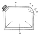
このような構造からなる軟包装袋用スパウト(1)を取り付ける軟包装袋(20)に使用するフィルムとしては、ガスバリア性や耐突き刺し性に優れ、透明性を有する複合フィルムが好ましく使用できる。 As a film used for the flexible packaging bag (20) to which the spout for flexible packaging bags (1) having such a structure is attached, a composite film having excellent gas barrier properties and puncture resistance and transparency can be preferably used.
より具体的には、二軸延伸ポリプロピレンフィルム、二軸延伸ポリエチレンテレフタレートフィルム、二軸延伸ナイロンフィルム等の基材フィルムに、高密度ポリエチレンフィルム,未延伸ポリプロピレンフィルム、線状低密度ポリエチレンフィルム等のシーラント層を積層した複合フィルム(必要に応じて基材フィルムとシーラント層の間に中間層として、既述の無機化合物蒸着プラスチックフィルムやエチレンビニルアルコール共重合樹脂フィルム等を積層しても良い。)が好ましく使用できる。 More specifically, a base film such as a biaxially stretched polypropylene film, a biaxially stretched polyethylene terephthalate film, or a biaxially stretched nylon film, and a sealant such as a high density polyethylene film, an unstretched polypropylene film, or a linear low density polyethylene film. A composite film in which layers are laminated (if necessary, an inorganic compound vapor-deposited plastic film, an ethylene vinyl alcohol copolymer resin film, or the like may be laminated as an intermediate layer between the base film and the sealant layer). It can be preferably used.
10‥‥軟包装袋用スパウト
11‥‥シール基部
12‥‥外側の筒体
13‥‥カテーテル接続筒体
14‥‥環状板
15‥‥注出口
16‥‥外側の筒体の先端周縁
17‥‥カテーテル接続筒体の先端周縁
18‥‥密封蓋
20‥‥軟包装袋
30‥‥内容物
40‥‥カテーテル
111‥‥リブ
121‥‥密封キャップ
131‥‥凸部
210‥‥スパウト
213‥‥カテーテル接続口
10.
Claims (4)
Priority Applications (1)
| Application Number | Priority Date | Filing Date | Title |
|---|---|---|---|
| JP2005085585A JP4635673B2 (en) | 2005-03-24 | 2005-03-24 | Soft packaging bag spout and fluid food soft packaging bag with the spout attached |
Applications Claiming Priority (1)
| Application Number | Priority Date | Filing Date | Title |
|---|---|---|---|
| JP2005085585A JP4635673B2 (en) | 2005-03-24 | 2005-03-24 | Soft packaging bag spout and fluid food soft packaging bag with the spout attached |
Publications (2)
| Publication Number | Publication Date |
|---|---|
| JP2006263154A JP2006263154A (en) | 2006-10-05 |
| JP4635673B2 true JP4635673B2 (en) | 2011-02-23 |
Family
ID=37199712
Family Applications (1)
| Application Number | Title | Priority Date | Filing Date |
|---|---|---|---|
| JP2005085585A Expired - Fee Related JP4635673B2 (en) | 2005-03-24 | 2005-03-24 | Soft packaging bag spout and fluid food soft packaging bag with the spout attached |
Country Status (1)
| Country | Link |
|---|---|
| JP (1) | JP4635673B2 (en) |
Families Citing this family (2)
| Publication number | Priority date | Publication date | Assignee | Title |
|---|---|---|---|---|
| JP2011201555A (en) * | 2010-03-24 | 2011-10-13 | Nippon Kimu Kk | Container with spout and plug |
| JP2016150080A (en) * | 2015-02-17 | 2016-08-22 | テルモ株式会社 | Reservoir bag |
Family Cites Families (3)
| Publication number | Priority date | Publication date | Assignee | Title |
|---|---|---|---|---|
| JPH11189249A (en) * | 1997-12-26 | 1999-07-13 | Fuji Seal Inc | Packaging bag with mouth member and packaging body |
| JP2002095721A (en) * | 2000-09-19 | 2002-04-02 | Bristol Myers Squibb Co | Infusion bag and its outlet device |
| JP2003081315A (en) * | 2001-09-05 | 2003-03-19 | Nippon Kimu Kk | Opening stopper and container with the same |
-
2005
- 2005-03-24 JP JP2005085585A patent/JP4635673B2/en not_active Expired - Fee Related
Also Published As
| Publication number | Publication date |
|---|---|
| JP2006263154A (en) | 2006-10-05 |
Similar Documents
| Publication | Publication Date | Title |
|---|---|---|
| US12214933B2 (en) | Tubular container and method for producing same | |
| JP4883940B2 (en) | Container mouth closing mechanism | |
| AU2003252884B9 (en) | Closure device for flexible pouches | |
| JP6492623B2 (en) | Infusion container | |
| KR102587730B1 (en) | Spout caps, spouts and containers with spout attachments | |
| WO2003043895A1 (en) | Packaging bag and method for production thereof | |
| JP4641078B2 (en) | Pouring tool and packaging bag with pouring tool | |
| JP4635673B2 (en) | Soft packaging bag spout and fluid food soft packaging bag with the spout attached | |
| JP2021079977A (en) | Spout unit for bag-shaped container | |
| JP6076072B2 (en) | Spout equipment and containers | |
| JP4121776B2 (en) | Outlet for bag-in-container | |
| JP2005206163A (en) | Mouth bag | |
| JP5772267B2 (en) | Packing bag for chemicals | |
| JPH1086953A (en) | Spout outlet assembly, its manufacturing equipment and spout packaging bag | |
| JP2001328662A (en) | Outlet union | |
| JP5090726B2 (en) | Container mouth closing mechanism | |
| JP4613551B2 (en) | Mouthed pouch | |
| JP2004074541A (en) | Packaging film | |
| JP2000142716A (en) | Indifinitely shaped container | |
| JP4743359B2 (en) | cap | |
| JPH1095441A (en) | Bag body made of plastic | |
| HK40057267A (en) | Tube container and method for manufacturing same | |
| JPH08119296A (en) | Packaging bag for liquid | |
| JP2021050033A (en) | Spout plug and packaging container | |
| JP2006089047A (en) | Spout |
Legal Events
| Date | Code | Title | Description |
|---|---|---|---|
| A621 | Written request for application examination |
Free format text: JAPANESE INTERMEDIATE CODE: A621 Effective date: 20080226 |
|
| A977 | Report on retrieval |
Free format text: JAPANESE INTERMEDIATE CODE: A971007 Effective date: 20100128 |
|
| A131 | Notification of reasons for refusal |
Free format text: JAPANESE INTERMEDIATE CODE: A131 Effective date: 20100209 |
|
| A521 | Request for written amendment filed |
Free format text: JAPANESE INTERMEDIATE CODE: A523 Effective date: 20100409 |
|
| A131 | Notification of reasons for refusal |
Free format text: JAPANESE INTERMEDIATE CODE: A131 Effective date: 20100804 |
|
| A521 | Request for written amendment filed |
Free format text: JAPANESE INTERMEDIATE CODE: A523 Effective date: 20100930 |
|
| TRDD | Decision of grant or rejection written | ||
| A01 | Written decision to grant a patent or to grant a registration (utility model) |
Free format text: JAPANESE INTERMEDIATE CODE: A01 Effective date: 20101026 |
|
| A01 | Written decision to grant a patent or to grant a registration (utility model) |
Free format text: JAPANESE INTERMEDIATE CODE: A01 |
|
| A61 | First payment of annual fees (during grant procedure) |
Free format text: JAPANESE INTERMEDIATE CODE: A61 Effective date: 20101108 |
|
| FPAY | Renewal fee payment (event date is renewal date of database) |
Free format text: PAYMENT UNTIL: 20131203 Year of fee payment: 3 |
|
| R150 | Certificate of patent or registration of utility model |
Ref document number: 4635673 Country of ref document: JP Free format text: JAPANESE INTERMEDIATE CODE: R150 Free format text: JAPANESE INTERMEDIATE CODE: R150 |
|
| R250 | Receipt of annual fees |
Free format text: JAPANESE INTERMEDIATE CODE: R250 |
|
| R250 | Receipt of annual fees |
Free format text: JAPANESE INTERMEDIATE CODE: R250 |
|
| LAPS | Cancellation because of no payment of annual fees |