JP4121776B2 - Outlet for bag-in-container - Google Patents
Outlet for bag-in-container Download PDFInfo
- Publication number
- JP4121776B2 JP4121776B2 JP2002143612A JP2002143612A JP4121776B2 JP 4121776 B2 JP4121776 B2 JP 4121776B2 JP 2002143612 A JP2002143612 A JP 2002143612A JP 2002143612 A JP2002143612 A JP 2002143612A JP 4121776 B2 JP4121776 B2 JP 4121776B2
- Authority
- JP
- Japan
- Prior art keywords
- spout
- bag
- film
- container
- contents
- Prior art date
- Legal status (The legal status is an assumption and is not a legal conclusion. Google has not performed a legal analysis and makes no representation as to the accuracy of the status listed.)
- Expired - Fee Related
Links
Images


Landscapes
- Bag Frames (AREA)
Description
【0001】
【発明の属する技術分野】
本発明は大型のバッグインコンテナー用注出口であって、その構造が簡単であって、内容物の取出しが安定してできる注出口の形状に関する。
【0002】
【従来の技術】
大容量の液体用のバッグインコンテナーは、大きな柔軟性のあるフィルムからなるバッグを、例えば、金属枠とプラスチック成形品からなる専用コンテナー等に収納してなる包装形式であって、業務用に用いられる液体、粘体物等の内容物の包装容器として多用されるものである。一般に前記バッグは、サイドガセットタイプのバッグであって、前記内容物を取出す目的の成形品による注出口(以下、注出口と記載する)を所定の位置に接着する場合が多い。このバッグインコンテナーの特徴は、内容物の取出しに従い、バッグが密封状態のままで変形するために、硬質容器のように容器内への大気流入がなくとも取出しが可能である。従って、内容物の取出しはじめから出し終わるまでの期間、大気(酸素)による内容物の変質が防止される。このような内容物の品質保全上の特性のほかに、使用後の包材として、そのバッグは圧縮でき、また、コンテナーも折り畳みが可能であり、また、外箱(コンテナー)と内袋(バッグ)とが分離できるので、使用後の内袋の廃棄、または返送が容易であり、また、単位内容物あたりの包材としては低価格である。
【0003】
また、従来のバッグインコンテナーの注出口と取出具とは、例えば、図6(a)に示すように、バッグBの上フィルムBbと下フィルムBaとにそれぞれに、相互に係合構造を有する成形品を熱接着したものが用いられている。上フィルムBbに熱接着される成形品( 以下、受型20bと記載する) は、上フィルムBbへの接着部となるフランジ部22bと袋の外側にある筒部21bとからなり、該筒部の内容物収納側の内面には、後述の押込型20aにおいて液体が漏れない状態に密封嵌合(以下、液密嵌合)するための嵌合部23bが設けられている。
一方、下フィルムBaに熱接着される成形品( 以下、押込型20a) は、下フィルムBaへの接着部となるフランジ部22aと袋の内側にある山型部21aおよび天部25とからなり、押込型20aには、受型20bに設けられた嵌合部23bと嵌合する嵌合部23aが設けられている。すなわち、押込型20aと受型20bとは、それぞれの嵌合部23a、23bとにおいて液密嵌合される形状となっている。
受型20b、押込型20bともに、バッグへの接着は、前記上フィルムBb、下フィルムBaのそれぞれに設けた孔部から筒部21b、山型部21aを突出させ、フランジ部上面と各フィルムの孔周縁のフィルム外面とを熱接着することによりなされる。接着された押込型20aは、受型20bとともに注出口組合体として、袋内の無菌状態を保持する機能と内容物の液密嵌合との機能を果たすものである。
図6(b)および図6(c)は、注出口20から内容物を取出す取出具30の構造と注出口から内容物を取出す状態を説明する断面概念図である。
【0004】
注出口組合体を装着した大型の袋に内容物を充填する場合には、通常、バッグを保存または輸送用コンテナー内に入れ、注出口組合体をコンテナーの所定の位置に固定した状態にして充填機にセットする。受型と充填機の充填口とをクランプし、必要であれば、注出口組合体の外面をCIP方式の殺菌後、充填機の充填部内部に装着した押し出しピンにより、受型に嵌合している押込型を押して、嵌合を外す。そして所定量の内容物を充填した後、再び、押込型の山部を受型の筒部内側に押し込み液密嵌合をするものである。また、内容物の充填は、注出口とは別の位置に設けた専用の充填口から行うこともある。
内容物の取出具は図6(b)および図6(c)に示すように、注出口と取出具とを、専用のクランプ36によって固定した後、取出具内のプッシャー部33により、プッシャー部ヘッド34が押込型20bを押して、押込型20aと受型20bとの嵌合を分離して内容物を取出具内に導入して、液体ポンプを介在させて取出具30の吐出口35から受け配管へと供給する。
【0005】
【発明が解決しようとする課題】
しかし、このタイプの注出口は、嵌合による液体密封性を保持するために、嵌合が極めて強固となり、内容物の取出具は、嵌合の分離機能等の機能を付加するために大掛かりな構造とそのコストも高価なものとなっていた。
そこで、より簡易なバッグインコンテナーの注出口と取出具とが使用されている。例えば、図7は、注出口とその取出具の構造を示す概念図で、それぞれ注出口の斜視図(a)、バッグに装着した状態を示す断面図(b)、突刺具の正面図(c)、注出口と取出具の断面図(d)、取出具の突き破りにより封止フィルムが破壊され内容物が取出される状態を示す断面図(e)である。
【0006】
注出口40の構造は、フランジ部43と内容物の注出路となる筒部41とが連接してなる。フランジ部43の下面には、筒部41の内容物側開口部を被覆してその周縁を熱接着してなる密封フィルム44が設けられ、また、フランジ部43の内周には、後述の突刺具54を係止する係止部45を設けている。
注出口40のバッグBへの装着は、図7(b)に示すように、バッグBに設けられた孔から、注出口40の筒部41を突出させ、フランジ部43の上面と孔周縁のバッグBの内面とを熱接着する。注出口40の筒部41内面には、後述の取出具50と螺合させるために内ねじ42が設けられている。
【0007】
この簡易バッグインコンテナーから内容物を取出すための取出具50は、図7(d)および図7(e)に示すように、密封フィルム44を突き破るための突刺具54と取出具本体からなり、取出具本体は、筒部51と、筒部51先端の外側には、注出口40の筒部41内面に設けられた内ねじ42と螺合する外ねじ52と、内容物の吐出口53が設けられている。
【0008】
簡易注出口40からの内容物の取出しは、注出口40の筒部41内に突刺具54を差し込み、取出具50の筒部51外面に設けた外ねじ52と注出口40の筒部41内面に設けた内ねじ42との螺合により、突刺具54を徐々に押し込み、密封フィルム44を押し破り、内容物を取出具50の筒部内に注入させるものである。しかし、密封フィルム44を突き破る瞬間において、内ねじ42と、外ねじ52との締付けが十分でないために、ねじ42、52間の隙間から内容物が漏れ出すことがあった。
本発明の課題は、構造が簡単であり、内容物の取出しが容易な、かつ、取出しの際に内容物が漏れるおそれのない注出口および取出具を提供することである。
【0009】
【課題を解決するための手段】
上記課題は、以下の本発明により解決することができる。すなわち、請求項1に記載した発明は、フランジ部と筒部とを有する成形品からなり、バッグに設けた孔部から前記筒部を外部に突出させ、前記のフランジ部の外面と前記バッグの孔部周縁の内面とを熱接着してなる注出口であって、前記フランジ部の内面に密封フィルムをシールし、前記筒部の先端をガスケット受け溝が形成された平面形状とし、かつ、前記密封フィルムのシール部が易剥離シールであって、かつ、前記密封フィルムのシール部の形状が、内側に向かう凸部を設ける形状であることを特徴とするバッグインコンテナー用注出口からなる。請求項2に記載した発明は、請求項1に記載に記載したバッグインコンテナー用注出口において、筒部の先端の開口部を被覆フィルムによりシールしたことを特徴とするものである。請求項3に記載した発明は、請求項1または請求項2したバッグインコンテナー用注出口において、注出口の開口部にキャップを嵌着したことを特徴とするものである。
【0010】
【発明の実施の形態】
本発明のバッグインコンテナーの注出口および該注出口からの内容物の取出具について、以下、図面などにより詳細に説明する。
【0011】
図1は、本発明のバッグインコンテナー用注出口の実施例を示す。(a)は注出口とキャップの斜視図、(b)は別の注出口の実施例を示す斜視図、(c)は図(a)に示す注出口の半断面正面図、(d)は図(b)に示す注出口の半断面正面図である。図2は、本発明のバッグインコンテナー用注出口のさらに別の実施例の説明図であり、(a)は半断面正面図、(b)は平面図、(c)は底面図である。
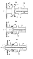
図3は、本発明のバッグインコンテナー用注出口をバッグに取付け状態を説明する図で、(a)はバッグに装着した状態を示す断面概念図、(b)はY部の拡大図である。図4は、本発明のバッグインボックスの注出口から内容物を取出す方法の実施例を示す概念図で、(a)は注出口と取出具との断面図、(b)は注出口に取出具を注出口に固定した状態、(c)は取出具の突き破りにより密封フィルムおよび封止フィルムが壊され内容物が取出される状態を示す図である。
図5は、本発明のバッグインボックスの別の注出口から内容物を取出す方法の実施例を示す概念図で、(a)は注出口と取出具との断面図、(b)は注出口に取出具を注出口に固定した状態、(c)は取出具の加圧により密封フィルムが剥離され内容物が取出される状態を示す図である。
【0012】
本発明にかかるバッグインコンテナー用注出口は、図1(a)に示すように、その注出口の先端を、ガスケット受け溝4が形成された平面形状とするもので、筒部の先端部3は、後述の取出具の受け面と重合し、クランプにより接合可能な形状とする。該注出口のフランジ部下面には、図1(c)に示すように、筒部に連接している開口部を密封したフィルム(以下、密封フィルムF)をヒートシールする。密封フィルムは、完全接着タイプでもよいし、易剥離性であってもよい。
筒部の先端部3には、図1(b)に示すように、筒部の開口部を被覆するフィルム(以下、被覆フィルムS)をヒートシールすることが望ましい。被覆フィルムSは、内容物の取出しの際に注出口部分に、注出口の周縁を滅菌するために過熱蒸気を噴霧して、注出口部の滅菌処理を行うが、過熱蒸気が密封フィルムFに直接噴霧されると、熱によって内容物の劣化の原因となることがある。被覆フィルムを設けることによって、密封フィルムFと被覆フィルムSとの間が断熱部となり、内容物の熱劣化を防止することができる。
また、筒部の先端には、図1(a)に示す成形キャップCを冠着させることによって、被覆フィルムSのない注出口の場合には、筒部内の塵埃による汚染防止、被覆フィルムSをシールした場合は該被覆フィルムの突刺しや摩擦等による損傷防止をすることができる。
【0013】
密封フィルムFのフランジへのヒートシールは、易剥離シールであってもよい。密封フィルムFを易剥離シールとする場合には、内容物の取出しの際に、図5(a)に示すような取出具10を用いてプッシャー部ヘッド14hの押圧により密封フィルムFを剥離するが、その際の剥離をし易くするために、密封フィルムFのシール部8の形状として、図2(c)に示すように、内側に向かう凸部7を設けることが望ましい。凸部7を設けることによって、剥離が常に、この凸部7から安定して行なわれ、密封フィルムFが不規則に破壊されることがなくなる。
また、注出口1の筒部の先端部3の形状は、さらに具体的には、図2(a)、図2(b)または、図4(a)に示すように、ガスケットgの受け溝4を形成することが好ましく、取出具10の受け部12にも対応するガスケット溝部4を形成する。
注出口1のバッグBへの装着は、図3(a)および図3(b)に示すように、バッグBに設けられた注出口装着孔から注出口1の筒部2を突出し、バッグBの内面とフランジ5の上面とをヒートシールすることによりなされる。
【0014】
次に、本発明のバッグインコンテナーの注出口1から内容物を取出すための取出具10の構造について説明する。取出具10は、図4(a)に示すように、バッグインコンテナーの注出口1の筒部先端部3に連結する形状の受け部12を形成した筒部11と筒部内部には、注出口の筒部開口部にシールされた被覆フィルムSおよび注出口内部にヒートシールされた密封フィルムFを突き破るための刃先14を押し込むプッシャー部13が組み込まれている。また、密封フィルムFを突き破ってバッグインコンテナーから取出具10の筒部内に注入する内容物の吐出口15が設けられている。該吐出口15にはボールバルブなどの開閉装置とを連結することができる。
【0015】
本発明のバッグインコンテナーの注出口1とその取出具10とにより、内容物を取出すには、図4(b)に示すように、まず、ガスケットgをそれぞれのガスケット受け溝4の中に挟持させて、注出口1の先端部3と取出具10の対応した受け部12とを合わせ、クランプ17により、取出具10を注出口1に固定する。次に、図4(b)および図4(c)に示すように、プッシャー部13によって、刃先14を注出口側に押し出して、被覆フィルムSを突き破り、次いで密封フィルムFを突き破ることによって、内容物がバッグ内から取出具10の筒部内に取出され、取出具10の吐出口15から受け配管(図示せず)へと供給される。
【0016】
注出口1における密封フィルムFが易剥離性にシールされたものであり、かつ、被覆フィルムSをシールしない場合の内容物の取出は、図5(a)に示すように、取出具10のプッシャー部13の先端、プッシャー部ヘッド14hをフラットまたは半球形とする。この場合の内容物の取出しは、図5(b)に示すように、まず、ガスケットgをそれぞれのガスケット受け溝4の中に挟持させて、注出口1の先端部3と取出具10の対応した受け部12とを重合させ、クランプ17により、取出具10を注出口1に固定する。次に、図5(c)に示すように、プレッシャー部ヘッド14hによって、密封フィルムFを押して、シール部を剥離することによって、内容物がバッグ内から取出具10の筒部内に取出され、取出具10の吐出口15から受け配管(図示せず)へと供給される。
【0017】
本発明におけるバッグインコンテナーの注出口1および取出具10の使用により、バッグインコンテナーからの内容物の取出しが確実、容易となった。すなわち、密封フィルムFを突き破りまたは剥離する前に、注出口1の先端部3と取出具10の受け部12とがクランプ17によって確実に固定されるので、図7(a)〜図7(e)に示すような構造の従来の密封フィルム44の突き破り方式のような注出口40と取出具50との結合時に見られた、ねじによるはめ込みの際に発生した初期漏れがの漏れの心配がなくなった。
【0018】
本発明の注出口1の材質は、内容物に接触しても衛生的に支障のない組成のものであって、そのフランジ部5においてバッグBに熱接着が可能であり、また、密封フィルムFあるいは被覆フィルムSが熱接着または易剥離性に熱接着し得るものであればよい。
【0019】
本発明に用いる注出口1のフランジ5の下部に易剥離性にヒートシールする場合、密封フィルムFは、バッグインコンテナーの輸送や保管の段階において、剥離破壊されることがなく、また、内容物に接触しても衛生的に支障のないものであればよい。例えば、注出口1が高密度ポリエチレンにより成形されていれば、密封フィルムFの材質例としては、ポリエステルフィルム12μm/接着層/ヒートシール層のような構成とし、ヒートシール層を構成する樹脂としては、低密度ポリエチレン、中密度ポリエチレン、高密度ポリエチレン、直鎖状低密度ポリエチレン、エチレンー酢酸ビニル共重合体等を用いることができる。ヒートシール層の形成は、ポリエステルフィルム面に接着層をアンカーコートとして塗布して、ヒートシール層を構成する樹脂を押出コート法により積層してもよいし、予め、ヒートシール層をフィルムとしておき、ドライラミネート法によりポリエステルフィルムと貼り合わせてもよい。
【0020】
また、密封フィルムFのシールを易剥離性とするには、例えば、注出口が高密度ポリエチレンにより成形されていれば、ポリエステルフィルム12μm/接着剤/EOフィルムのような構成にすればよい。この場合、EOフィルムとしては、低密度ポリエチレン樹脂50重量%と高密度ポリエチレン40重量%とポリプロピレン樹脂10重量%とをブレンドして、Tダイ式製膜機により、フィルム化し、ラミネート面にコロナ放電処理により表面処理を施したフィルムとすることが望ましい。
また、安定した易剥離をさせるために、フランジ5の下面と密封フィルムFとの熱接着のシール形状としては、図2(c)に示すような、内部に凸部7を形成することが好ましい。
【0021】
注出口1の筒部開口部に被覆フィルムSをシールする場合、被覆フィルムSの材質としては、注出口1にヒートシール可能であり、取出具10の刃先により突き破り可能な材質であればよい。
【0022】
次に、本発明のバッグインコンテナーに収納する内容物を充填するバッグBについて説明する。バッグBは、合成樹脂を製膜してなる単体フィルムまたは多層フィルムからなる単袋または2重袋以上の多重袋であり、袋形式としては、通常サイドガセットタイプの製袋をする。
【0023】
本発明のバッグインコンテナーの注出口1を装着するバッグBに用いるフィルムは、内容物の種類、充填量等を考慮し、柔軟性、屈曲強度、バリア性などにより、最も適切な材質と厚さを選定する。特に内容物が液体であって、長時間にわたって、振動による屈曲を受ける条件においては、フィルムがその屈曲疲労により、ピンホール(微細孔)を発生し易い。従ってこのような条件下において用いられるフィルムは強靱な特性を有する材質からなるものが選択される。バッグインコンテナーのバッグに用いられるフィルムを構成する樹脂としては、低密度ポリエチレン、エチレン・酢酸ビニル共重合体、直鎖状低密度ポリエチレン、アイオノマー、シングルサイト系触媒を用いて重合したエチレンーα・オレフィン共重合体などを挙げることができる。また、これらの樹脂の単独層でもよく、また、共押出法製膜による多層フィルムであってもよい。多層フィルムとする場合には、エチレン・酢酸ビニル共重合体のけん化物やポリビニルアルコール樹脂等のハイバリア性樹脂を用いることができる。
【0024】
また、バッグBを構成するフィルムには、通常のラミネート法によって積層された多層フィルムを用いてもよく、その場合には、アルミニウム箔のような金属箔をはじめ、ポリエステル、ポリアミド、ポリ塩化ビニリデン、ポリプロピレン等からなる未延伸または延伸のフィルム、また、これらのフィルムにアルミニウム等の金属を蒸着したフィルム、さらにまた、酸化アルミニウム等の金属酸化物や酸化珪素などの無機酸化物を蒸着したフィルムを用いることもできる。
バッグインコンテナーのバッグを形成するフィルムは、一般的な製膜法、例えば、Tダイによるキャスティング法、円形ダイスによるインフレーション法等により得ることができる。また、そのフィルムは、共押出による多層構成のフィルムとしてもよい。
【0025】
本発明のバッグインコンテナーに用いるバッグBの材質として、例えば、2重袋の構成の場合には、外側フィルムとして、2軸延伸ナイロンフィルム(厚さ15μm)にアルミニウムを蒸着したポリエステルフィルム(厚さ12μm)をドライラミネートし、さらにポリエステルフィルム面にシングルサイト系触媒を用いて重合した直鎖状低密度ポリエチレン(以下、LLD−PE▲1▼)からなるフィルム(密度0.923、厚さ60μm)をドライラミネートしたフィルムとし、内側フィルムとして、外側から、密度0.923のLLD−PE▲1▼(厚さ20μm)と、密度0.890のLLD−PE▲2▼(厚さ50μm)と、密度0.921のLLD−PE▲3▼(厚さ20μm)との3層共押出しフィルムとする。この構成例の外装フィルム、ナイロン内装フィルムを略号で示すと
外装フィルム
ON15μm/DL/VM−PET12μm/DL/LLD−PE▲1▼60μm
内側フィルム
LLD−PE▲1▼20μm//LLD−PE▲2▼50μm//LLD−PE▲3▼20μm
となる。
[略号等 ON:2軸延伸ナイロンフィルム、DL:ドライラミネート、
VM−PET:アルミニウムを蒸着したポリエステルフィルム、LLD−PE▲1▼、LLD−PE▲2▼、LLD−PE▲3▼はいずれもシングルサイト系触媒を用いて重合した直鎖状低密度ポリエチレン、//:共押出しの層の接着界面]
バッグの材質と各フィルムの厚さ、多層フィルムを用いる場合の各層の材質、各層の厚さなどは、内容物の種類、流通条件其の他によって設計されるものである。
【0026】
本発明のバッグインコンテナーの注出口におけるコンテナーは、移送、多段積み、保管等の際の取扱い易さに加えて、振動、衝撃による破袋やピンホールの発生等からバッグBを守るためのものであり、収納する内容物の内容量、保存、保管、輸送の各種条件により、材質として段ボール、木材、金属、合成樹脂等の単体または組み合わせによってその構造が設計される。
コンテナーには、バッグBに装着した注出口1を係止する開口部が形成される。また、コンテナーは、使用前、使用後のバッグの収納されていない時には、折り畳み可能な構造であることが望ましい。
【0027】
このように、注出口1の筒部の先端部3をガスケット受け溝4が形成された平面形状とし、取出具10の受け部12を注出口の先端部3の形状に対応させることによって、取出具10を注出口1に接合が極めて容易、かつ確実な固定が可能となる。その接合方法としては、前記注出口1の先端部3と取出具の受け部12とを重合し、クランプ17により固定、接合すればよく作業が容易である。
本発明のバッグインコンテナーの注出口1と取出具10の使用により、密封フィルムFの突き破りまたは剥離前に、注出口の先端部3と取出具10の受け部12とを合わせクランプ17によって固定してから、被覆フィルムSおよび密封フィルムFを破りあるいは剥離して内容物を取出すので、従来の簡易バッグインコンテナーの取出具を用いる場合のような、漏れの心配もなく、注出口の脱着も容易となった。
また、密封フィルムFを、注出口1のフランジ5と易剥離性に接着することによって、取出具10のプッシャー部ヘッド14hの押圧により、接着面において剥離して、突き破り方法の際に見られたような密封フィルムFの破片が内容物に混入するおそれがなくなった。
【0028】
【発明の効果】
大型のバッグインコンテナーの注出口から内容物を取出すのに、注出口と取出具とはガスケット受け溝を有するフラット形状の結合としたために、セットが容易であり、また、セット後に、密封フィルムを取出具に内蔵の押出具により突き破りまたは剥離するため、取出の際の液漏れの心配がなく、安定した取出しが可能となった。
【図面の簡単な説明】
【図1】本発明のバッグインコンテナー用注出口の実施例を示す。(a)は注出口とキャップの斜視図、(b)は別の注出口の実施例を示す斜視図、(c)は図(a)に示す注出口の半断面正面図、(d)は図(b)に示す注出口の半断面正面図である。
【図2】本発明のバッグインコンテナー用注出口のさらに別の実施例の説明図であり、(a)は半断面正面図、(b)は平面図、(c)は底面図である。
【図3】本発明のバッグインコンテナー用注出口をバッグに取付け状態を説明する図で、(a)はバッグに装着した状態を示す断面概念図、(b)はY部の拡大図である。
【図4】本発明のバッグインボックスの注出口から内容物を取出す方法の実施例を示す概念図で、(a)は注出口と取出具との断面図、(b)は注出口に取出具を注出口に固定した状態、(c)は取出具の突き破りにより密封フィルムおよび封止フィルムが壊され内容物が取出される状態を示す図である。
【図5】本発明のバッグインボックスの別の注出口から内容物を取出す方法の実施例を示す概念図で、(a)注出口と取出具との断面図、(b)注出口に取出具を注出口に固定した状態、(c)取出具の加圧により密封フィルムが剥離され内容物が取出される状態を示す図である。
【図6】従来の嵌合型注出口と取出具との実施例を示すいずれも断面図で、(a)は嵌合前の注出口の断面図、(b)は嵌合した注出口と取出具の断面概念図、(c)は取出具を注出口に固定して嵌合部を分離し内容物が取出される状態を示す断面図である。
【図7】従来の簡易型注出口とその取出具の構造を示す概念図で、(a)は注出口の斜視図、(b)はバッグに装着した状態を示す断面図、(c)は突刺具、(d)は注出口と取出具の断面図、(e)は取出具の突き破りにより密封フィルムが破壊され内容物が取出される状態を示す断面図である。
【符号の説明】
B バッグ
C キャップ
F 密封フィルム
S 被覆フィルム
1 注出口
2 筒部
3 先端部
4 ガスケット受け溝
g ガスケット
5 フランジ
6 リブ
7 凸部
8 シール部
10 取出具
11 筒部
12 受け部
13 プッシャー部
14 刃先
14h プッシャー部ヘッド
15 吐出口
17 クランプ
20 注出口
20a 押込型
20b 受型
21a 山型部
21b 筒部
22 フランジ部
23 嵌合部
25 天部
30 取出具
31 筒部
32 クランプ
33 プッシャー部
34 プッシャー部ヘッド
35 吐出口
36 クランプ
40 簡易注出口
41 筒部
42 内ねじ
43 フランジ部
44 密封フィルム
45 係止部
50 取出具
51 筒部
52 外ねじ
53 吐出口
54 突刺具[0001]
BACKGROUND OF THE INVENTION
The present invention relates to a large-sized bag-in-container spout, which has a simple structure and can stably take out contents.
[0002]
[Prior art]
A large-capacity liquid bag-in-container is a packaging format in which a bag made of a large flexible film is stored in a dedicated container made of a metal frame and a plastic molded product, for business use. It is frequently used as a packaging container for contents such as liquid and mucilage. In general, the bag is a side gusset type bag, and a spout (hereinafter referred to as a spout) of a molded product for taking out the contents is often adhered to a predetermined position. The bag-in-container is characterized in that the bag is deformed in a sealed state as the contents are taken out, so that the bag can be taken out without inflowing into the container like a hard container. Therefore, alteration of the contents due to the atmosphere (oxygen) is prevented during the period from the beginning to the end of taking out the contents. In addition to the quality preservation characteristics of the contents, as a packaging material after use, the bag can be compressed, the container can be folded, and the outer box (container) and inner bag (bag). ) Can be separated, the inner bag after use can be easily discarded or returned, and the packaging material per unit content is inexpensive.
[0003]
Moreover, as shown in FIG. 6A, for example, the conventional bag-in-container spout and take-out tool have an engaging structure with each other on the upper film Bb and the lower film Ba of the bag B, respectively. A heat-bonded molded product is used. A molded product thermally bonded to the upper film Bb (hereinafter referred to as a receiving
On the other hand, a molded product (hereinafter referred to as a
Both the receiving
FIG. 6B and FIG. 6C are cross-sectional conceptual diagrams illustrating the structure of the
[0004]
When filling the contents of a large bag fitted with a spout assembly, the bag is usually placed in a container for storage or transportation and filled with the spout assembly fixed in place in the container. Set in the machine. Clamp the receiving mold and the filling port of the filling machine. If necessary, the outer surface of the spout assembly is sterilized by the CIP method, and then fitted into the receiving mold by an extrusion pin mounted inside the filling part of the filling machine. Press the push-in mold that is in place to release the mating. Then, after filling a predetermined amount of the contents, the push-type peak portion is again pushed into the inner side of the receiving-type cylinder portion and liquid-tight fitting is performed. Moreover, the filling of the contents may be performed from a dedicated filling port provided at a position different from the spout.
As shown in FIGS. 6 (b) and 6 (c), the content take-out tool is fixed to the outlet and the take-out tool by a
[0005]
[Problems to be solved by the invention]
However, this type of spout has an extremely strong fitting in order to maintain the liquid tightness by fitting, and the contents takeout tool is large in order to add functions such as a separation function for fitting. The structure and its cost were also expensive.
Therefore, a simpler bag-in-container outlet and take-out tool are used. For example, FIG. 7 is a conceptual diagram showing the structure of the spout and its take-out tool, and is a perspective view (a) of the spout, a cross-sectional view (b) showing a state where the spout is mounted, and a front view (c) of the piercing tool. ), A cross-sectional view (d) of the spout and the extraction tool, and a cross-sectional view (e) showing a state in which the sealing film is broken and the contents are taken out by breaking through the extraction tool.
[0006]
The structure of the
As shown in FIG. 7 (b), the
[0007]
As shown in FIGS. 7 (d) and 7 (e), the take-
[0008]
To take out the contents from the
An object of the present invention is to provide a spout and an extraction tool that are simple in structure, easy to take out the contents, and have no risk of the contents leaking out.
[0009]
[Means for Solving the Problems]
The above problems can be solved by the present invention described below. That is, the invention described in claim 1 is formed of a molded product having a flange portion and a cylindrical portion, and projects the cylindrical portion to the outside through a hole provided in the bag, and the outer surface of the flange portion and the bag The spout is formed by thermally bonding the inner surface of the peripheral edge of the hole, and a sealing film is sealed on the inner surface of the flange portion, and the tip of the cylindrical portion has a planar shape in which a gasket receiving groove is formed. And the sealing part of the said sealing film is an easily peelable seal, and the shape of the sealing part of the said sealing film is a shape which provides the convex part which goes inside. It consists of a spout for a bag-in-container characterized by this. The invention described in
[0010]
DETAILED DESCRIPTION OF THE INVENTION
Hereinafter, the spout of the bag-in container of the present invention and the contents extracting tool from the spout will be described in detail with reference to the drawings.
[0011]
FIG. 1 shows an embodiment of a spout for a bag-in container according to the present invention. (A) is a perspective view of the spout and the cap, (b) is a perspective view showing another embodiment of the spout, (c) is a half sectional front view of the spout shown in FIG. It is a half section front view of the spout shown in Drawing (b). FIG. 2 is an explanatory view of still another embodiment of the bag-in-container spout of the present invention, in which (a) is a half sectional front view, (b) is a plan view, and (c) is a bottom view.
FIG. 3 is a view for explaining a state in which the bag-in-container spout of the present invention is attached to the bag, (a) is a conceptual cross-sectional view showing a state where the bag-in-container is attached to the bag, and (b) is an enlarged view of the Y part. . FIG. 4 is a conceptual diagram showing an embodiment of a method for taking out the contents from the spout of the bag-in-box according to the present invention, where (a) is a cross-sectional view of the spout and the takeout tool, and (b) is taken out at the spout. (C) is a figure which shows the state from which the sealing film and the sealing film are broken by the breakthrough of an extraction tool, and the contents are taken out.
FIG. 5 is a conceptual diagram showing an embodiment of a method for taking out contents from another spout of the bag-in-box according to the present invention, wherein (a) is a cross-sectional view of the spout and a take-out tool, and (b) is a spout. (C) is a figure which shows the state from which a sealing film peels by the pressurization of an extraction tool, and the content is taken out.
[0012]
As shown in FIG. 1A, the bag-in-container spout according to the present invention has a front end of the spout having a planar shape in which a
As shown in FIG. 1B, it is desirable to heat-seal a film (hereinafter referred to as a coating film S) covering the opening of the cylindrical portion at the
In addition, by attaching a molding cap C shown in FIG. 1A to the tip of the cylindrical portion, in the case of a spout without the covering film S, contamination prevention due to dust in the cylindrical portion, the covering film S is provided. When sealed, the coating film can be prevented from being damaged by piercing or friction.
[0013]
The heat seal to the flange of the sealing film F may be an easy peel seal. When the sealing film F is an easily peelable seal, the sealing film F is peeled off by pressing the pusher portion head 14h using the
Further, more specifically, the shape of the
As shown in FIGS. 3A and 3B, the spout 1 is attached to the bag B by projecting the
[0014]
Next, the structure of the
[0015]
In order to take out the contents by the spout 1 of the bag-in-container of the present invention and its take-out
[0016]
When the sealing film F at the spout 1 is easily peeled and the covering film S is not sealed, the content is taken out as shown in FIG. The tip of the
[0017]
By using the bag-in-container spout 1 and take-out
[0018]
The material of the spout 1 of the present invention has a composition that does not sanitize even when it comes into contact with the contents, and can be thermally bonded to the bag B at the
[0019]
When heat-sealing to the lower part of the
[0020]
In order to make the seal of the sealing film F easily peelable, for example, if the spout is formed of high-density polyethylene, a configuration such as
Moreover, in order to make it easy to peel easily, as a sealing shape of the heat bonding between the lower surface of the
[0021]
When sealing the coating film S to the cylindrical opening of the spout 1, the material of the covering film S may be any material that can be heat sealed to the spout 1 and can be pierced by the cutting edge of the
[0022]
Next, the bag B filled with the contents stored in the bag-in container of the present invention will be described. The bag B is a single bag made of a synthetic resin film or a single bag made of a multilayer film or a multiple bag of double or more bags, and the bag type is usually a side gusset type bag.
[0023]
The film used for the bag B to which the spout 1 of the bag-in-container of the present invention is attached is considered to be the most suitable material and thickness depending on the kind of contents, filling amount, etc., flexibility, bending strength, barrier properties, etc. Is selected. In particular, when the contents are liquid and the film is bent by vibration for a long time, the film tends to generate pinholes (fine holes) due to bending fatigue. Therefore, the film used under such conditions is selected from a material having tough characteristics. The resin used for the bag-in-container bag is low-density polyethylene, ethylene / vinyl acetate copolymer, linear low-density polyethylene, ionomer, and ethylene-α / olefin polymerized using a single-site catalyst. A copolymer etc. can be mentioned. Moreover, the single layer of these resin may be sufficient, and the multilayer film by co-extrusion film forming may be sufficient. When a multilayer film is used, a high barrier resin such as a saponified ethylene / vinyl acetate copolymer or a polyvinyl alcohol resin can be used.
[0024]
In addition, a multilayer film laminated by a normal laminating method may be used for the film constituting the bag B. In that case, a metal foil such as an aluminum foil, polyester, polyamide, polyvinylidene chloride, An unstretched or stretched film made of polypropylene or the like, a film in which a metal such as aluminum is deposited on these films, or a film in which a metal oxide such as aluminum oxide or an inorganic oxide such as silicon oxide is deposited is used. You can also
The film forming the bag of the bag-in-container can be obtained by a general film forming method, for example, a casting method using a T die, an inflation method using a circular die, or the like. The film may be a film having a multilayer structure by coextrusion.
[0025]
As a material of the bag B used for the bag-in-container of the present invention, for example, in the case of a double bag configuration, as an outer film, a polyester film (thickness) in which aluminum is vapor-deposited on a biaxially stretched nylon film (
Exterior film
ON 15 μm / DL / VM-
Inner film
LLD-PE (1) 20 μm // LLD-PE (2) 50 μm // LLD-PE (3) 20 μm
It becomes.
[Abbreviations, etc. ON: biaxially stretched nylon film, DL: dry laminate,
VM-PET: Polyester film on which aluminum is deposited, LLD-PE (1), LLD-PE (2), and LLD-PE (3) are all linear low-density polyethylene polymerized using a single-site catalyst, //: Adhesive interface of co-extruded layer]
The material of the bag, the thickness of each film, the material of each layer in the case of using a multilayer film, the thickness of each layer, and the like are designed according to the type of contents, distribution conditions, and the like.
[0026]
The container at the spout of the bag-in container of the present invention is intended to protect the bag B from vibrations, impact breakage, pinholes, etc. in addition to ease of handling during transfer, multi-stage stacking, storage, etc. The structure is designed with a single material or a combination of corrugated cardboard, wood, metal, synthetic resin, etc. as materials depending on the contents of the contents to be stored, storage, storage, and transportation.
The container is formed with an opening for locking the spout 1 attached to the bag B. Further, it is desirable that the container has a foldable structure when the used bag is not stored before and after use.
[0027]
In this way, the
By using the spout 1 and take-out
In addition, the sealing film F was peeled off on the adhesive surface by pressing the pusher part head 14h of the
[0028]
【The invention's effect】
To take out the contents from the large bag-in-container's spout, the spout and the unloader are connected in a flat shape with a gasket receiving groove. Since it is pierced or peeled off by the pusher built in the takeout tool, there is no risk of liquid leakage during takeout, and stable takeout is possible.
[Brief description of the drawings]
FIG. 1 shows an embodiment of a spout for a bag-in-container according to the present invention. (A) is a perspective view of the spout and the cap, (b) is a perspective view showing another embodiment of the spout, (c) is a half sectional front view of the spout shown in FIG. It is a half section front view of the spout shown in Drawing (b).
FIG. 2 is an explanatory view of still another embodiment of the bag-in-container spout of the present invention, (a) is a half sectional front view, (b) is a plan view, and (c) is a bottom view.
FIGS. 3A and 3B are diagrams illustrating a state where the bag-in-container spout of the present invention is attached to a bag, wherein FIG. 3A is a conceptual cross-sectional view showing a state where the bag-in container spout is attached to the bag, and FIG. .
4A and 4B are conceptual diagrams showing an embodiment of a method for taking out contents from a spout of a bag-in-box according to the present invention, in which FIG. 4A is a cross-sectional view of the spout and a take-out tool, and FIG. (C) is a figure which shows the state from which the sealing film and the sealing film are broken by the breakthrough of an extraction tool, and the contents are taken out.
FIG. 5 is a conceptual diagram showing an embodiment of a method for taking out contents from another spout of the bag-in-box according to the present invention; (a) a cross-sectional view of the spout and a take-out tool; It is a figure which shows the state which the sealing film peeled by the state which fixed the extraction tool to the spout, (c) pressurization of the extraction tool, and the content was taken out.
6A and 6B are cross-sectional views each showing an embodiment of a conventional fitting-type spout and a take-out tool, wherein FIG. 6A is a cross-sectional view of a spout before fitting, and FIG. Sectional conceptual diagram of the extraction tool, (c) is a cross-sectional view showing a state in which the extraction tool is fixed to the spout, the fitting portion is separated, and the contents are extracted.
FIG. 7 is a conceptual diagram showing the structure of a conventional simplified spout and its take-out tool, where (a) is a perspective view of the spout, (b) is a cross-sectional view showing a state of being attached to a bag, and (c) is a cross-sectional view. The piercing tool, (d) is a cross-sectional view of the spout and the extraction tool, and (e) is a cross-sectional view showing a state in which the sealing film is broken and the contents are taken out by the breakage of the extraction tool.
[Explanation of symbols]
B bag
C cap
F sealing film
S coated film
1 outlet
2 cylinder
3 Tip
4 Gasket receiving groove
g Gasket
5 Flange
6 Ribs
7 Convex
8 Seal part
10 Extractor
11 Tube
12 receiving part
13 Pusher section
14 cutting edge
14h Pusher head
15 Discharge port
17 Clamp
20 outlet
20a Push-in type
20b receiving type
21a Yamagata
21b Tube part
22 Flange
23 Fitting part
25 Heaven
30 Extractor
31 Tube
32 Clamp
33 Pusher
34 Pusher head
35 Discharge port
36 Clamp
40 Simple spout
41 Tube
42 Internal thread
43 Flange
44 Sealing film
45 Locking part
50 Extractor
51 Tube
52 External thread
53 Discharge port
54 Puncture tool
Claims (3)
Priority Applications (1)
| Application Number | Priority Date | Filing Date | Title |
|---|---|---|---|
| JP2002143612A JP4121776B2 (en) | 2002-05-17 | 2002-05-17 | Outlet for bag-in-container |
Applications Claiming Priority (1)
| Application Number | Priority Date | Filing Date | Title |
|---|---|---|---|
| JP2002143612A JP4121776B2 (en) | 2002-05-17 | 2002-05-17 | Outlet for bag-in-container |
Publications (2)
| Publication Number | Publication Date |
|---|---|
| JP2003335391A JP2003335391A (en) | 2003-11-25 |
| JP4121776B2 true JP4121776B2 (en) | 2008-07-23 |
Family
ID=29703569
Family Applications (1)
| Application Number | Title | Priority Date | Filing Date |
|---|---|---|---|
| JP2002143612A Expired - Fee Related JP4121776B2 (en) | 2002-05-17 | 2002-05-17 | Outlet for bag-in-container |
Country Status (1)
| Country | Link |
|---|---|
| JP (1) | JP4121776B2 (en) |
Families Citing this family (6)
| Publication number | Priority date | Publication date | Assignee | Title |
|---|---|---|---|---|
| JP2008247459A (en) * | 2007-03-30 | 2008-10-16 | Daiwa Can Co Ltd | Perfumed container |
| KR101023264B1 (en) * | 2010-06-11 | 2011-03-21 | 한정식 | Pack |
| JP6362975B2 (en) * | 2014-09-12 | 2018-07-25 | 凸版印刷株式会社 | Industrial bag inner bag and industrial bag |
| JP6604108B2 (en) * | 2015-09-16 | 2019-11-13 | 株式会社スリーボンド | Viscous material supply apparatus and viscous material supply method |
| JP2018065576A (en) * | 2016-10-17 | 2018-04-26 | 住商グローバル・ロジスティクス株式会社 | Pouring port fixing device for bag-in-box |
| JP7459587B2 (en) * | 2020-03-17 | 2024-04-02 | 大日本印刷株式会社 | Aseptic filling mechanism |
-
2002
- 2002-05-17 JP JP2002143612A patent/JP4121776B2/en not_active Expired - Fee Related
Also Published As
| Publication number | Publication date |
|---|---|
| JP2003335391A (en) | 2003-11-25 |
Similar Documents
| Publication | Publication Date | Title |
|---|---|---|
| KR101183789B1 (en) | Sealing mechanism for container opening | |
| JP3750703B2 (en) | Flexible container for liquid | |
| JP2001130598A (en) | Storage bag | |
| EP3854720B1 (en) | Tubular container and method for manufacturing same | |
| JP4010038B2 (en) | Sealed packaging bag having an opening / closing part | |
| JP4816126B2 (en) | Packaging bag with dispensing tool | |
| JP4121776B2 (en) | Outlet for bag-in-container | |
| JP3622465B2 (en) | Pouch with a branched chamber | |
| JP4449964B2 (en) | Standing pouch with a branched chamber | |
| JPH10211961A (en) | Viscous matter packaging container, and distributing device | |
| US20040065056A1 (en) | Patch for flexible container | |
| JPH1086953A (en) | Pouring port assembly, apparatus for manufacturing the same and packaging bag with the ejection port | |
| JP3998778B2 (en) | Outlet association | |
| JP4079123B2 (en) | Pouch with a branched chamber | |
| JP3403522B2 (en) | Liquid storage bag | |
| JP4202449B2 (en) | Puncture sealing lid and packaging | |
| JP2000211659A (en) | Spout assembly body | |
| JP3678836B2 (en) | Packaging container | |
| JP4099864B2 (en) | Pressure-resistant paper container | |
| JP4184477B2 (en) | Tubular container | |
| JP3668298B2 (en) | Packaging container | |
| JPH11171250A (en) | Repeatedly openable and closable sealed plastic container | |
| JP2006021828A (en) | Storage device | |
| JP2002002789A (en) | Spout assembly | |
| JP2000142716A (en) | Indifinitely shaped container |
Legal Events
| Date | Code | Title | Description |
|---|---|---|---|
| A621 | Written request for application examination |
Free format text: JAPANESE INTERMEDIATE CODE: A621 Effective date: 20050511 |
|
| A977 | Report on retrieval |
Free format text: JAPANESE INTERMEDIATE CODE: A971007 Effective date: 20070528 |
|
| A131 | Notification of reasons for refusal |
Free format text: JAPANESE INTERMEDIATE CODE: A131 Effective date: 20070620 |
|
| A521 | Written amendment |
Free format text: JAPANESE INTERMEDIATE CODE: A523 Effective date: 20070810 |
|
| TRDD | Decision of grant or rejection written | ||
| A01 | Written decision to grant a patent or to grant a registration (utility model) |
Free format text: JAPANESE INTERMEDIATE CODE: A01 Effective date: 20080403 |
|
| A61 | First payment of annual fees (during grant procedure) |
Free format text: JAPANESE INTERMEDIATE CODE: A61 Effective date: 20080430 |
|
| FPAY | Renewal fee payment (event date is renewal date of database) |
Free format text: PAYMENT UNTIL: 20110509 Year of fee payment: 3 |
|
| R150 | Certificate of patent or registration of utility model |
Free format text: JAPANESE INTERMEDIATE CODE: R150 |
|
| FPAY | Renewal fee payment (event date is renewal date of database) |
Free format text: PAYMENT UNTIL: 20120509 Year of fee payment: 4 |
|
| FPAY | Renewal fee payment (event date is renewal date of database) |
Free format text: PAYMENT UNTIL: 20120509 Year of fee payment: 4 |
|
| FPAY | Renewal fee payment (event date is renewal date of database) |
Free format text: PAYMENT UNTIL: 20130509 Year of fee payment: 5 |
|
| FPAY | Renewal fee payment (event date is renewal date of database) |
Free format text: PAYMENT UNTIL: 20140509 Year of fee payment: 6 |
|
| LAPS | Cancellation because of no payment of annual fees |