JP4635556B2 - Developing device, image forming apparatus, and image forming system - Google Patents
Developing device, image forming apparatus, and image forming system Download PDFInfo
- Publication number
- JP4635556B2 JP4635556B2 JP2004305860A JP2004305860A JP4635556B2 JP 4635556 B2 JP4635556 B2 JP 4635556B2 JP 2004305860 A JP2004305860 A JP 2004305860A JP 2004305860 A JP2004305860 A JP 2004305860A JP 4635556 B2 JP4635556 B2 JP 4635556B2
- Authority
- JP
- Japan
- Prior art keywords
- developer
- arithmetic average
- average height
- developer supply
- roller
- Prior art date
- Legal status (The legal status is an assumption and is not a legal conclusion. Google has not performed a legal analysis and makes no representation as to the accuracy of the status listed.)
- Expired - Fee Related
Links
Images


Landscapes
- Liquid Developers In Electrophotography (AREA)
- Wet Developing In Electrophotography (AREA)
- Rolls And Other Rotary Bodies (AREA)
Description
本発明は、現像装置、画像形成装置、及び、画像形成システムに関する。 The present invention relates to a developing device, an image forming apparatus, and an image forming system.
この種の画像形成装置としては、例えば、潜像を担持するための像担持体の一例としての感光体と、液体現像剤(以下、単に、現像剤とも呼ぶ)によって感光体に担持された潜像を現像するための現像装置と、を有する画像形成装置が知られている。かかる画像形成装置は、ホストコンピュータなどの外部装置から画像信号等が送信されると、感光体上に潜像を形成する。そして、感光体に形成され、担持された潜像は、感光体の回転に伴って現像位置に至り、現像装置によって現像され、感光体上に現像剤像が形成される。 As this type of image forming apparatus, for example, a photoconductor as an example of an image carrier for carrying a latent image and a latent image carried on the photoconductor by a liquid developer (hereinafter also simply referred to as a developer). 2. Description of the Related Art An image forming apparatus having a developing device for developing an image is known. Such an image forming apparatus forms a latent image on a photoreceptor when an image signal or the like is transmitted from an external device such as a host computer. Then, the latent image formed and carried on the photosensitive member reaches the developing position as the photosensitive member rotates, and is developed by the developing device, so that a developer image is formed on the photosensitive member.
上記の現像装置は、感光体上に形成された潜像を現像するという既述の機能等を実現するために、現像剤を担持するための現像剤担持体の一例としての現像ローラと、表面に凹部を有し、該凹部に保持された現像剤を現像ローラに供給するための現像剤供給部材の一例としての現像剤供給ローラと、当該現像剤供給ローラの表面に当接して現像剤供給ローラ上の現像剤の量を規制するための規制部材の一例としての規制ブレードと、を有している。 The developing device described above includes a developing roller as an example of a developer carrying member for carrying a developer, and a surface in order to realize the above-described function of developing a latent image formed on a photoreceptor. And a developer supply roller as an example of a developer supply member for supplying the developer held in the recess to the developing roller, and a developer supply in contact with the surface of the developer supply roller And a regulating blade as an example of a regulating member for regulating the amount of developer on the roller.
そして、現像剤供給ローラは、該現像剤供給ローラ上の現像剤の量が規制ブレードにより規制された後に(すなわち、現像剤供給ローラ上の現像剤が凹部に保持された現像剤を残して掻き取られた後に)、凹部に保持された現像剤を現像ローラに供給する。現像ローラへ供給された現像剤は、潜像の現像に供される。
前述したとおり、現像剤供給ローラは、現像剤供給ローラ上の現像剤が凹部に保持された現像剤を残して掻き取られた後に、凹部に保持された現像剤を現像ローラに供給する。そのため、前記凹部の大きさは、現像ローラに供給される現像剤の現像剤量が適正な量になるように、その大きさが厳密に決められている。 As described above, the developer supply roller supplies the developer held in the recess to the developing roller after the developer on the developer supply roller is scraped off leaving the developer held in the recess. Therefore, the size of the concave portion is strictly determined so that the amount of developer supplied to the developing roller is an appropriate amount.
しかしながら、凹部に保持された現像剤が確実に現像ローラへ供給されない場合や、非凹部上の現像剤が、十分に掻き取られずに、現像ローラへ供給される場合には、現像剤供給ローラにより現像ローラへ供給される現像剤の現像剤量が不適正な量となる。かかる場合には、潜像を現像して画像を形成した際に、その画質に劣化が生ずることとなる。 However, when the developer held in the concave portion is not reliably supplied to the developing roller, or when the developer on the non-concave portion is not sufficiently scraped off and supplied to the developing roller, the developer supplying roller The amount of developer supplied to the developing roller is an inappropriate amount. In such a case, when the latent image is developed to form an image, the image quality is deteriorated.
本発明は、かかる課題に鑑みてなされたものであり、その目的とするところは、画質の劣化を適切に防止する現像装置、画像形成装置、及び、画像形成システムを実現することにある。 SUMMARY An advantage of some aspects of the invention is that it realizes a developing device, an image forming apparatus, and an image forming system that appropriately prevent deterioration in image quality.
主たる本発明は、液体現像剤を担持するための現像剤担持体と、凹部と、算術平均高さが前記凹部の算術平均高さよりも大きい非凹部と、を表面に有し、前記凹部に保持された液体現像剤を前記現像剤担持体に供給するための現像剤供給部材と、前記現像剤供給部材の前記表面に当接して前記現像剤供給部材上の液体現像剤の量を規制するための規制部材と、を有し、前記現像剤供給部材は、前記現像剤担持体が圧接部にて該現像剤供給部材の前記表面に圧接した状態で、該現像剤担持体に液体現像剤を供給し、前記現像剤担持体の前記圧接部の算術平均高さは、前記凹部の算術平均高さよりも大きいことを特徴とする現像装置である。 The main present invention has a developer carrying body for carrying a liquid developer, a concave portion, and a non-concave portion whose arithmetic average height is larger than the arithmetic average height of the concave portion, and is held in the concave portion. For regulating the amount of the liquid developer on the developer supply member in contact with the surface of the developer supply member and a developer supply member for supplying the liquid developer to the developer carrier The developer supply member is configured to apply a liquid developer to the developer carrier in a state where the developer carrier is in pressure contact with the surface of the developer supply member at a pressure contact portion. The developing device is characterized in that the arithmetic average height of the pressure contact portion of the developer carrier is larger than the arithmetic average height of the concave portion .
本発明の他の特徴については、本明細書及び添付図面の記載により明らかにする。 Other features of the present invention will become apparent from the description of this specification and the accompanying drawings.
本明細書及び添付図面の記載により、少なくとも次のことが明らかにされる。 At least the following will be made clear by the description of the present specification and the accompanying drawings.
液体現像剤を担持するための現像剤担持体と、凹部と、算術平均高さが前記凹部の算術平均高さよりも大きい非凹部と、を表面に有し、前記凹部に保持された液体現像剤を前記現像剤担持体に供給するための現像剤供給部材と、前記現像剤供給部材の前記表面に当接して前記現像剤供給部材上の液体現像剤の量を規制するための規制部材と、を有することを特徴とする現像装置。
かかる現像装置によれば、画質の劣化を適切に防止することが可能となる。
A liquid developer having a developer carrying body for carrying a liquid developer, a concave portion, and a non-concave portion whose arithmetic average height is larger than the arithmetic average height of the concave portion and held on the concave portion A developer supply member for supplying the developer carrier to the developer carrier, and a regulating member for abutting the surface of the developer supply member to regulate the amount of the liquid developer on the developer supply member; A developing device comprising:
According to such a developing device, it is possible to appropriately prevent deterioration in image quality.
また、前記現像剤担持体と、前記現像剤供給部材は、それぞれ、円柱状の現像剤担持ローラと、円柱状の現像剤供給ローラであることとしてもよい。 The developer carrier and the developer supply member may be a cylindrical developer carrying roller and a cylindrical developer supply roller, respectively.
また、前記凹部は、溝であることとしてもよい。
かかる場合には、凹部を簡易に加工できる。
The concave portion may be a groove.
In such a case, the recess can be easily processed.
また、前記現像剤供給部材は、前記現像剤担持体が圧接部にて該現像剤供給部材の前記表面に圧接した状態で、該現像剤担持体に液体現像剤を供給し、前記現像剤担持体の前記圧接部の算術平均高さは、前記凹部の算術平均高さよりも大きいこととしてもよい。
かかる場合には、現像剤供給部材の凹部から現像剤担持体へ現像剤が適切に供給されることとなる。
The developer supply member supplies the developer carrier to the developer carrier in a state where the developer carrier is in pressure contact with the surface of the developer supply member at a pressure contact portion, and the developer carrier. The arithmetic average height of the pressure contact portion of the body may be larger than the arithmetic average height of the concave portion.
In such a case, the developer is appropriately supplied from the concave portion of the developer supply member to the developer carrier.
また、前記非凹部の算術平均高さは、前記現像剤担持体の前記圧接部の算術平均高さよりも小さいこととしてもよい。
かかる場合には、非凹部が圧接部を損傷させること、を適切に防止することができる。
The arithmetic average height of the non-concave portion may be smaller than the arithmetic average height of the press contact portion of the developer carrier.
In such a case, it is possible to appropriately prevent the non-concave portion from damaging the pressure contact portion.
また、前記規制部材の、前記表面へ当接する当接部、の算術平均高さは、前記凹部の算術平均高さよりも小さいこととしてもよい。また、前記液体現像剤は、非ニュートン流体であることとしてもよい。 Moreover, the arithmetic average height of the contact part which contact | abuts to the said surface of the said control member is good also as being smaller than the arithmetic average height of the said recessed part. The liquid developer may be a non-Newtonian fluid.
また、液体現像剤を担持するための現像剤担持体と、凹部と、算術平均高さが前記凹部の算術平均高さよりも大きい非凹部と、を表面に有し、前記凹部に保持された液体現像剤を前記現像剤担持体に供給するための現像剤供給部材と、前記現像剤供給部材の前記表面に当接して前記現像剤供給部材上の液体現像剤の量を規制するための規制部材と、を有し、前記現像剤担持体と、前記現像剤供給部材は、それぞれ、円柱状の現像剤担持ローラと、円柱状の現像剤供給ローラであり、前記凹部は、溝であり、前記現像剤供給部材は、前記現像剤担持体が圧接部にて該現像剤供給部材の前記表面に圧接した状態で、該現像剤担持体に液体現像剤を供給し、前記現像剤担持体の前記圧接部の算術平均高さは、前記凹部の算術平均高さよりも大きくて、前記非凹部の算術平均高さは、前記現像剤担持体の前記圧接部の算術平均高さよりも小さくて、前記規制部材の、前記表面へ当接する当接部、の算術平均高さは、前記凹部の算術平均高さよりも小さくて、前記液体現像剤は、非ニュートン流体であることを特徴とする現像装置も実現可能である。
このようにすれば、既述の総ての効果を奏するため、本発明の目的がより有効に達成される。
Further, a liquid having a developer carrying body for carrying a liquid developer, a concave portion, and a non-concave portion whose arithmetic average height is larger than the arithmetic average height of the concave portion and held in the concave portion. A developer supply member for supplying the developer to the developer carrier, and a regulating member for regulating the amount of liquid developer on the developer supply member in contact with the surface of the developer supply member And the developer carrier and the developer supply member are respectively a cylindrical developer carrier roller and a cylindrical developer supply roller, and the recess is a groove, The developer supply member supplies a liquid developer to the developer carrier in a state where the developer carrier is in pressure contact with the surface of the developer supply member at a pressure contact portion, and the developer carrier The arithmetic average height of the press contact portion is larger than the arithmetic average height of the concave portion. The arithmetic average height of the non-concave portion is smaller than the arithmetic average height of the pressure contact portion of the developer carrier, and the arithmetic average height of the contact portion of the regulating member that contacts the surface is It is also possible to realize a developing device in which the liquid developer is a non-Newtonian fluid that is smaller than the arithmetic average height of the recesses.
In this way, the effects of the present invention can be achieved more effectively because all the effects described above can be achieved.
また、潜像を担持するための像担持体と、該像担持体に担持された潜像を現像する現像装置であって、液体現像剤を担持するための現像剤担持体と、凹部と、算術平均高さが前記凹部の算術平均高さよりも大きい非凹部と、を表面に有し、前記凹部に保持された液体現像剤を前記現像剤担持体に供給するための現像剤供給部材と、前記現像剤供給部材の前記表面に当接して前記現像剤供給部材上の液体現像剤の量を規制するための規制部材と、を有する現像装置と、を備えたことを特徴とする画像形成装置も実現可能である。
かかる画像形成装置によれば、画質の劣化を適切に防止することが可能となる。
An image carrier for carrying a latent image, a developing device for developing the latent image carried on the image carrier, a developer carrier for carrying a liquid developer, a recess, A non-recessed portion having an arithmetic average height larger than the arithmetic average height of the recessed portion, and a developer supply member for supplying the liquid developer held in the recessed portion to the developer carrier, An image forming apparatus comprising: a developing device having a regulating member that abuts on the surface of the developer supplying member and regulates the amount of the liquid developer on the developer supplying member. Is also feasible.
According to such an image forming apparatus, it is possible to appropriately prevent deterioration in image quality.
また、コンピュータ、及び、このコンピュータに接続可能な画像形成装置であって、潜像を担持するための像担持体と、該像担持体に担持された潜像を現像する現像装置であって、液体現像剤を担持するための現像剤担持体と、凹部と、算術平均高さが前記凹部の算術平均高さよりも大きい非凹部と、を表面に有し、前記凹部に保持された液体現像剤を前記現像剤担持体に供給するための現像剤供給部材と、前記現像剤供給部材の前記表面に当接して前記現像剤供給部材上の液体現像剤の量を規制するための規制部材と、を有する現像装置と、を備えた画像形成装置、を有することを特徴とする画像形成システムも実現可能である。
かかる画像形成システムによれば、画質の劣化を適切に防止することが可能となる。
A computer and an image forming apparatus connectable to the computer, an image carrier for carrying a latent image, and a developing device for developing the latent image carried on the image carrier; A liquid developer having a developer carrying body for carrying a liquid developer, a concave portion, and a non-concave portion whose arithmetic average height is larger than the arithmetic average height of the concave portion and held on the concave portion A developer supply member for supplying the developer carrier to the developer carrier, and a regulating member for abutting the surface of the developer supply member to regulate the amount of the liquid developer on the developer supply member; It is also possible to realize an image forming system including an image forming apparatus including a developing device including
According to such an image forming system, it is possible to appropriately prevent deterioration in image quality.
===画像形成装置の全体構成例===
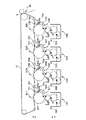
次に、図1を用いて、画像形成装置としてレーザビームプリンタ(以下、プリンタともいう)10を例にとって、その概要について説明する。図1は、プリンタ10を構成する主要構成要素を示した図である。なお、図1には、矢印にて上下方向を示しており、例えば、現像ユニット50Y、50M、50C、50Kは、プリンタ10の下部に配置されており、中間転写体70は、プリンタ10の上部に配置されている。
=== Example of Overall Configuration of Image Forming Apparatus ===
Next, an outline of a laser beam printer (hereinafter also referred to as a printer) 10 as an example of the image forming apparatus will be described with reference to FIG. FIG. 1 is a diagram illustrating main components constituting the printer 10. In FIG. 1, the vertical direction is indicated by arrows. For example, the developing
本実施の形態に係るプリンタ10は、図1に示すように、4つの現像部15Y、15M、15C、15K、中間転写体70、二次転写ユニット80を有し、さらに、不図示の定着ユニット、ユーザへの報知手段をなし液晶パネルでなる表示ユニット、及び、これらのユニット等を制御しプリンタとしての動作を司る制御ユニット100(図2)を有している。
As shown in FIG. 1, the printer 10 according to the present embodiment includes four developing
現像部15Y、15M、15C、15Kは、それぞれ、イエロー(Y)現像剤、マゼンタ(M)現像剤、シアン(C)現像剤、ブラック(K)現像剤で潜像を現像する機能を有している。現像部15Y、15M、15C、15Kの構成は同様であるので、以下、現像部15Yについて説明する。
The developing
現像部15Yは、図1に示すように、像担持体の一例としての感光体20Yの回転方向に沿って、帯電ユニット30Y、露光ユニット40Y、現像装置の一例としての現像ユニット50Y、一次転写ユニット60Y、除電ユニット73Y、感光体クリーニングユニット75Yを有している。
感光体20Yは、円筒状の基材とその外周面に形成された感光層を有し、中心軸を中心に回転可能であり、本実施の形態においては、図1中の矢印で示すように時計回りに回転する。
帯電ユニット30Yは、感光体20Yを帯電するための装置であり、露光ユニット40Yは、レーザを照射することによって帯電された感光体20Y上に潜像を形成する装置である。この露光ユニット40Yは、半導体レーザ、ポリゴンミラー、F−θレンズ等を有しており、パーソナルコンピュータ、ワードプロセッサ等の不図示のホストコンピュータから入力された画像信号に基づいて、変調されたレーザを帯電された感光体20Y上に照射する。
現像ユニット50Yは、感光体20Y上に形成された潜像を、イエロー(Y)現像剤を用いて現像するための装置である。現像ユニット50Yの詳細については後述する。
As shown in FIG. 1, the developing
The
The
The developing
一次転写ユニット60Yは、感光体20Yに形成されたイエロー現像剤像を中間転写体70に転写するための装置である。一次転写ユニット60Y、60M、60C、60Kにより、4色の現像剤が順次重ねて転写された場合には、中間転写体70にフルカラー現像剤像が形成される。
中間転写体70は、複数の支持ローラに張架されたエンドレスのベルトであり、感光体20Y、20M、20C、20Kと当接しながら回転駆動される。
二次転写ユニット80は、中間転写体70上に形成された単色現像剤像やフルカラー現像剤像を紙、フィルム、布等の媒体に転写するための装置である。
不図示の定着ユニットは、媒体上に転写された単色現像剤像やフルカラー現像剤像を紙等の媒体に融着させて永久像とするための装置である。
The
The
The
A fixing unit (not shown) is a device for fusing a single color developer image or a full color developer image transferred onto a medium onto a medium such as paper to form a permanent image.
除電ユニット73Yは、一次転写ユニット60Yによって中間転写体70上に現像剤像が転写された後に、感光体20Y上の残留電荷を除去する装置である。
感光体クリーニングユニット75Yは、感光体20Yの表面に当接されたゴム製の感光体クリーニングブレード76Yを有し、一次転写ユニット60Yによって中間転写体70上に現像剤像が転写された後に、感光体20Y上に残存する現像剤を感光体クリーニングブレード76Yにより掻き落として除去するための装置である。
The
The photosensitive
制御ユニット100は、図2に示すようにメインコントローラ101と、ユニットコントローラ102とで構成され、メインコントローラ101には画像信号及び制御信号が入力され、この画像信号及び制御信号に基づく指令に応じてユニットコントローラ102が前記各ユニット等を制御して画像を形成する。
As shown in FIG. 2, the
次に、このように構成されたプリンタ10の動作について、他の構成要素にも言及しつつ説明する。 Next, the operation of the printer 10 configured as described above will be described with reference to other components.
まず、不図示のホストコンピュータからの画像信号及び制御信号がインターフェイス(I/F)112を介してプリンタ10のメインコントローラ101に入力されると、このメインコントローラ101からの指令に基づくユニットコントローラ102の制御により感光体20Y、20M、20C、20K、現像ユニット50Y、50M、50C、50Kに備えられた後述する現像ローラ、及び、中間転写体70等が回転する。感光体20Y、20M、20C、20Kは、回転しながら、帯電位置において帯電ユニット30Y、30M、30C、30Kにより順次帯電される。
First, when an image signal and a control signal from a host computer (not shown) are input to the
感光体20Y、20M、20C、20Kの帯電された領域は、感光体20Y、20M、20C、20Kの回転に伴って露光位置に至り、露光ユニット40Y、40M、40C、40Kによって、イエローY、マゼンタM、シアンC、ブラックKの画像情報に応じた潜像が該領域に形成される。
The charged regions of the photoconductors 20Y, 20M, 20C, and 20K reach the exposure position as the
感光体20Y、20M、20C、20K上に形成された潜像は、感光体20Y、20M、20C、20Kの回転に伴って現像位置に至り、現像ユニット50Y、50M、50C、50Kによって現像される。これにより、感光体20Y、20M、20C、20K上に現像剤像が形成される。
The latent images formed on the
感光体20Y、20M、20C、20K上に形成された現像剤像は、感光体20Y、20M、20C、20Kの回転に伴って一次転写位置に至り、一次転写ユニット60Y、60M、60C、60Kによって、中間転写体70に転写される。この際、一次転写ユニット60Y、60M、60C、60Kには、現像剤の帯電極性とは逆の極性の一次転写電圧が印加される。この結果、各々の感光体20Y、20M、20C、20K上に形成された4色の現像剤像は、中間転写体70に重なり合って転写され、中間転写体70上にはフルカラー現像剤像が形成される。
The developer images formed on the
中間転写体70上に形成されたフルカラー現像剤像は、中間転写体70の回転に伴って二次転写位置に至り、二次転写ユニット80によって媒体に転写される。なお、媒体は、不図示の給紙トレイから、各種ローラを介して二次転写ユニット80へ搬送される(図1中の矢印は、媒体の搬送方向を表している)。また、転写動作を行う際、二次転写ユニット80は中間転写体70に押圧されるとともに二次転写電圧が印加される。
媒体に転写されたフルカラー現像剤像は、定着ユニットによって加熱加圧されて媒体に融着される。
The full color developer image formed on the
The full color developer image transferred to the medium is heated and pressed by the fixing unit and fused to the medium.
一方、感光体20Y、20M、20C、20Kは一次転写位置を経過した後に、除電ユニット73Y、73M、73C、73Kによって除電され、さらに、感光体クリーニングユニット75Y、75M、75C、75Kに支持された感光体クリーニングブレード76Y、76M、76C、76Kによって、その表面に付着している現像剤が掻き落とされ、次の潜像を形成するための帯電に備える。掻き落とされた現像剤は、感光体クリーニングユニット75Y、75M、75C、75Kが備える残存現像剤回収部に回収される。
On the other hand, the
===制御ユニットの概要===
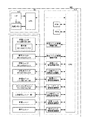
次に、制御ユニット100の構成について図2を参照しつつ説明する。制御ユニット100のメインコントローラ101は、インターフェイス112を介してホストコンピュータと接続され、このホストコンピュータから入力された画像信号を記憶するための画像メモリ113を備えている。ユニットコントローラ102は、装置本体の各ユニット(帯電ユニット30Y、30M、30C、30K、露光ユニット40Y、40M、40C、40K、現像ユニット50Y、50M、50C、50K、一次転写ユニット60Y、60M、60C、60K、除電ユニット73Y、73M、73C、73K、感光体クリーニングユニット75Y、75M、75C、75K、二次転写ユニット80、定着ユニット、表示ユニット)と電気的に接続され、それらが備えるセンサからの信号を受信することによって、各ユニットの状態を検出しつつ、メインコントローラ101から入力される信号に基づいて、各ユニットを制御する。
=== Overview of Control Unit ===
Next, the configuration of the
===現像ユニットの構成例===
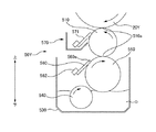
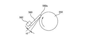
次に、図3乃至図6を用いて、現像ユニットの構成例について説明する。図3は、現像ユニットの主要構成要素を示した断面図である。図4は、現像剤供給ローラ550の表面を表した斜視概念図である。図5A乃至図5Cは現像剤供給ローラ550表面に設けられた溝の形状を示す断面図である。図6は、規制ブレード560のトレール規制を表した模式図である。なお、図3においては、図1同様、矢印にて上下方向を示しており、例えば、現像ローラ510は、現像剤汲み上げローラ540よりも上方にある。また、図を解りやすくするために、図4には、実際の現像剤供給ローラ550よりも溝550aの数がより少ない現像剤供給ローラ550を示している。
=== Configuration Example of Development Unit ===
Next, a configuration example of the developing unit will be described with reference to FIGS. FIG. 3 is a cross-sectional view showing main components of the developing unit. FIG. 4 is a conceptual perspective view showing the surface of the
プリンタ10には、現像ユニットとして、ブラック(K)現像剤を収容したブラック現像ユニット50K、マゼンタ(M)現像剤を収容したマゼンタ現像ユニット50M、シアン(C)現像剤を収容したシアン現像ユニット50C、及び、イエロー(Y)現像剤を収容したイエロー現像ユニット50Yが設けられているが、各現像ユニットの構成は同様であるので、以下、イエロー現像ユニット50Yについて説明する。
The printer 10 includes, as developing units, a black developing
イエロー現像ユニット50Yは、現像剤担持体(現像剤担持ローラ)の一例としての現像ローラ510と、現像剤収容部530と、現像剤汲み上げローラ540と、現像剤供給部材の一例としての現像剤供給ローラ550と、規制部材の一例としての規制ブレード560と、現像ローラクリーニングユニット570とを有している。
The yellow developing
現像剤収容部530は、感光体20Yに形成された潜像を現像するための現像剤Dを収容する。この現像剤収容部530に収容されている現像剤Dは、従来一般的に使用されている、Isopar(商標:エクソン)をキャリアとした低濃度(1〜2wt%程度)かつ低粘度の、常温で揮発性を有する揮発性液体現像剤ではなく、高濃度かつ高粘度の、常温で不揮発性を有する不揮発性液体現像剤Dである。すなわち、本実施の形態に係る液体現像剤Dは、パラフィンオイル等からなる不揮発性かつ絶縁性の低粘度キャリア液中に、平均粒径0.1〜5μm程度の樹脂、顔料等からなるトナー粒子を高濃度(5〜40wt%程度)に分散させることにより、高粘度(100〜10000mPa・s程度)となった現像剤Dである。また、本実施の形態に係る液体現像剤Dは、所謂非ニュートン流体である。すなわち、ニュートン流体である前記キャリア液中に、前記トナー粒子を高濃度に分散させた結果、前記液体現像剤Dは、非ニュートン性を有する流体となる。
The
現像剤汲み上げローラ540は、現像剤収容部530に収容されている現像剤Dを汲み上げて現像剤供給ローラ550へ搬送する。この現像剤汲み上げローラ540は、その下部が現像剤収容部530に収容された現像剤Dに浸されており、また、現像剤供給ローラ550から、約1mmの幅を持って離間している。
The developer pump-up
さらに、現像剤汲み上げローラ540は、その中心軸を中心として回転可能であり、当該中心軸は、現像剤供給ローラ550の回転中心軸よりも下方にある。また、現像剤汲み上げローラ540は、現像剤供給ローラ550の回転方向(図3において時計方向)と同じ方向(図3において時計方向)に回転する。なお、現像剤汲み上げローラ540は、現像剤収容部530に収容された現像剤Dを汲み上げて現像剤供給ローラ550へ搬送する機能を有するとともに、現像剤Dを適正な状態に維持するために現像剤Dを撹拌する機能をも有している。
Further, the
現像剤供給ローラ550は、現像剤収容部530から現像剤汲み上げローラ540により搬送された現像剤Dを現像ローラ510へ供給する。この現像剤供給ローラ550は、鉄等金属性の円柱状ローラの表面に図4に示すような凹部の一例としての溝550aを均一かつ螺旋状に設けたものであり、その直径は約25mmである。すなわち、現像剤供給ローラ550の表面には、図4に示すように、凹部の一例としての溝550aと、非凹部の一例としての非溝部550bと、が設けられている。本実施の形態における現像剤供給ローラ550は、当該溝550aとして、図5Aに示すような台形の断面を有する溝550aを備えているが、例えば、図5Bに示すような逆三角形の断面を有する溝を備えてもよいし、図5Cに示すような半円形の断面を有する溝を備えてもよい。
The
なお、現像剤供給ローラ550の表面のうち、非凹部の一例としての非溝部550bの算術平均高さRa(JIS B 0601−2001準拠)は、凹部の一例としての溝550aの算術平均高さRaよりも大きくなっている。その値は、それぞれ、約0.15μm、約0.05μmである。また、本実施の形態における現像剤供給ローラ550の溝寸法は、図5Aに示すとおり、溝ピッチ約170μm、山幅約45μm、谷幅約30μm、溝深さ約50μmである。
Of the surface of the
さらに、現像剤供給ローラ550は、当該現像剤供給ローラ550上の現像剤Dを現像ローラ510に適切に転写するために、その表面が、当該現像ローラ510の後述する弾性体の層に圧接している。また、現像剤供給ローラ550は、その中心軸を中心として回転可能であり、当該中心軸は、現像ローラ510の回転中心軸よりも下方にある。また、現像剤供給ローラ550は、現像ローラ510の回転方向(図3において反時計方向)と逆の方向(図3において時計方向)に回転する。
Further, the
規制ブレード560は、現像剤供給ローラ550の表面に当接部560aにて当接して、現像剤供給ローラ上の現像剤Dの量を規制する。すなわち、当該規制ブレード560は、現像剤供給ローラ550上の余剰現像剤を掻き取って、現像ローラ510に供給する現像剤供給ローラ550上の現像剤D、を計量する役割を果たす。この規制ブレード560は、弾性体としてのウレタンゴムからなり、鉄等金属製の規制ブレード支持部材562より支持されている。なお、規制ブレードの560の前記当接部560aの算術平均高さRaは、前述した溝550aの算術平均高さRa(約0.05μm)よりも小さくなっており、その値は、約0.02μmである。また、規制ブレード560のゴム硬度は、JIS−Aで約77度であり、規制ブレード560の、現像剤供給ローラ550表面への当接部560a、の硬度(約77度)は、後述する現像ローラ510の弾性体の層の、現像剤供給ローラ550表面への圧接部510a、の硬度(約85度)よりも低くなっている。
The
また、規制ブレード560は、そのエッジ部が現像剤供給ローラ550の表面に当接しており、いわゆるエッジ規制を行う。また、図6に示されるように、規制ブレード560は、その先端が現像剤供給ローラ550の回転方向の下流側に向くように配置されており、いわゆるトレール規制を行う。図6に示されるように、本実施の形態において、そのトレール角度は約10度である。
Further, the edge of the
現像ローラ510は、感光体20Yに担持された潜像を現像剤Dにより現像するために、現像剤Dを担持して感光体20Yと対向する現像位置に搬送する。この現像ローラ510は、鉄等金属製の内芯の外周部に、導電性を有する弾性体の層を備えた円柱状の部材であり、その直径は約20mmである。また、弾性体の層は、二層構造になっており、その内層として、ゴム硬度がJIS−A約30度で、厚み約5mmのウレタンゴムが、その表層(外層)として、ゴム硬度がJIS−A約85度で、厚み約30μmのウレタンゴムが備えられている。
The developing
そして、現像ローラ510は、前記表層が圧接部510aとなって、弾性変形された状態で現像剤供給ローラ550に圧接している。すなわち、現像ローラ510が前記圧接部510aにて現像剤供給ローラ550の表面に圧接した状態で、現像剤供給ローラ550が、現像ローラ510に現像剤Dを供給する。なお、現像ローラ510の圧接部510aの算術平均高さRaは、前述した溝550aの算術平均高さRa(約0.05μm)よりも大きくなっており、その値は、約0.3μmである。したがって、前述した非溝部550bの算術平均高さRa(約0.15μm)は、当該圧接部510aの算術平均高さRaよりも小さくなっている。また、現像ローラ510は、前記表層が圧接部510aとなって、感光体20Yにも圧接している。
The developing
また、現像ローラ510は、その中心軸を中心として回転可能であり、当該中心軸は、感光体20Yの回転中心軸よりも下方にある。また、現像ローラ510は、感光体20Yの回転方向(図3において時計方向)と逆の方向(図3において反時計方向)に回転する。なお、感光体20Y上に形成された潜像を現像する際には、現像ローラ510と感光体20Yとの間に電界が形成される。
Further, the developing
現像ローラクリーニングユニット570は、現像ローラ510の表面に当接されたゴム製の現像ローラクリーニングブレード571を有し、前記現像位置で現像が行われた後に、現像ローラ510上に残存する現像剤Dを現像ローラクリーニングブレード571により掻き落として除去するための装置である。
The developing
このように構成されたイエロー現像ユニット50Yにおいて、現像剤汲み上げローラ540が、その中心軸回りに回転することによって、現像剤収容部530に収容されている現像剤Dを汲み上げて現像剤供給ローラ550へ搬送する。
In the yellow developing
現像剤供給ローラ550に搬送された現像剤Dは、現像剤供給ローラ550の回転によって、規制ブレード560の当接位置に至る。そして、当該当接位置を通過する際に、現像剤Dの余剰分が規制ブレード560によって掻き取られ、現像ローラ510に供給される現像剤Dの現像剤量が計量される。すなわち、現像剤供給ローラ550には、前述したとおり、溝550aが設けられているから、現像剤供給ローラ550に当接する規制ブレード560は、現像剤供給ローラ550上の現像剤Dを溝550aに保持された現像剤Dを残して掻き取ることとなる。また、現像ローラ510に供給される現像剤Dの現像剤量が適正な量になるように溝550aの寸法が決められているので、規制ブレード560が現像剤供給ローラ550上の現像剤Dを掻き取った際には、溝550aによって適正な量に計量された現像剤Dが溝550aに残存することとなる。
The developer D conveyed to the
現像剤供給ローラ550の溝550aに保持された現像剤Dは、現像剤供給ローラ550のさらなる回転によって、現像ローラ510との圧接位置に至る。当該圧接位置に至った現像剤Dは、現像剤供給ローラ550と現像ローラ510が圧接することにより生ずる圧力の作用より、現像剤供給ローラ550から現像ローラ510へ転写され、現像ローラ510上には現像剤Dの薄膜が形成される。
The developer D held in the
このようにして現像ローラ510上に形成された現像剤Dの薄膜は、現像ローラ510の回転によって、感光体20Yに対向する現像位置(すなわち、感光体20Yとの圧接位置)に至り、該現像位置にて所定の大きさの電界下で感光体20Y上に形成された潜像の現像に供される。現像位置を通過した現像ローラ510上の現像剤Dは、現像ローラ510のさらなる回転によって、現像ローラクリーニングブレード571の当接位置に至る。そして、当該当接位置を通過する際に、現像ローラクリーニングブレード571によって、現像ローラ510の表面に付着している現像剤Dが掻き落とされ、掻き落とされた現像剤Dは、現像ローラクリーニングユニット570が備える残存現像剤回収部に回収される。
The developer D thin film formed on the developing
上述したとおり、本実施形態に係る現像装置は、現像剤Dを担持するための現像ローラ510と、溝550aと算術平均高さRaが溝550aの算術平均高さRaよりも大きい非溝部550bとを表面に有し、溝550aに保持された現像剤Dを現像ローラ510に供給するための現像剤供給ローラ550と、現像剤供給ローラ550の表面に当接して現像剤供給ローラ550上の現像剤Dの量を規制するための規制ブレード560と、を有している。このことにより、画質の劣化を適切に防止することが可能となる。
As described above, the developing device according to the present embodiment includes the developing
すなわち、発明が解決しようとする課題の項等で説明したとおり、現像剤供給ローラ550は、当該現像剤供給ローラ550上の現像剤Dが溝550aに保持された現像剤Dを残して掻き取られた後に、溝550aに保持された現像剤Dを現像ローラ510に供給する。そのため、溝550aの大きさは、現像ローラ510に供給される現像剤Dの現像剤量が適正な量になるように、その大きさが厳密に決められている。
That is, as described in the section of the problem to be solved by the invention, the
しかしながら、溝550aに保持された現像剤Dが確実に現像ローラ510へ供給されない場合や、非溝部550b上の現像剤Dが、十分に掻き取られずに、現像ローラ510へ供給される場合には、現像剤供給ローラ550により現像ローラ510へ供給される現像剤Dの現像剤量が不適正な量となる。かかる場合には、潜像を現像して画像を形成した際に、その画質に劣化が生ずることとなる。
However, when the developer D held in the
かかる課題を解決するために、本実施の形態に係る現像装置においては、非溝部550bの算術平均高さRaが、溝550aの算術平均高さRaよりも大きくなっている。このように、溝550aの算術平均粗さRaと非溝部550bの算術平均粗さRaとの間に差を設けることにより、現像ローラ510へ供給される現像剤Dの現像剤量が不適正な量となることを適切に防止することができる。
In order to solve such a problem, in the developing device according to the present embodiment, the arithmetic average height Ra of the
すなわち、非溝部550bの算術平均高さRaがより大きい場合には、非溝部550bと当該非溝部550bに当接する規制ブレード560との間に十分な大きさの摩擦力が発生するから、規制ブレード560が、非溝部550b上の現像剤Dを適切に掻き取ることが可能となり、非溝部550b上の現像剤Dが現像ローラ510へ供給されることを抑止することができる(逆に、非溝部550bの算術平均高さRaがより小さい場合には、規制ブレード560が、非溝部550bに対して滑るようになるから、規制ブレード560による非溝部550b上の現像剤Dの掻き取りが不十分なものとなる)。また、溝550aの算術平均高さRaがより小さい場合には、溝550aに付着した現像剤Dが、溝550aから離れ易くなるから、溝550aに保持された現像剤Dが、溝550a内に残存することなく、確実に現像ローラ510へ供給される。
That is, when the arithmetic average height Ra of the
したがって、本実施の形態に係る現像装置においては、現像剤供給ローラ550により現像ローラ510へ供給される現像剤Dの現像剤量が適正な量となり、延いては、画質の劣化が適切に防止されることとなる。
Therefore, in the developing device according to the present embodiment, the developer amount of the developer D supplied to the developing
===溝の形成方法について===
上記効果を適切に発揮させるためには、前述したとおり、算術平均高さRaが小さい溝550aを現像剤供給ローラ550に形成する必要がある。ここでは、このような溝550aを形成する方法の一例について、図7を用いて説明する。図7は、溝550aを形成する方法を説明するための説明図である。
=== About Method of Forming Grooves ===
In order to appropriately exhibit the above effect, it is necessary to form the
当該溝550aは、旋盤等を用いて現像剤供給ローラ550を切削加工することにより、形成される。
すなわち、現像剤供給ローラ550は、回転可能な主軸と一体的に回転するチャックに固定され、主軸の回転に伴ってチャックに固定された現像剤供給ローラ550が回転する。そして、切削工具としてのバイトBが、回転する現像剤供給ローラ550に当てられて、当該バイトBが現像剤供給ローラ550の軸方向に送られる。このことにより、現像剤供給ローラ550が切削されて、その表面に螺旋状の溝550aが形成されることとなる。
The
That is, the
ここで、本実施の形態においては、最終的な溝550aを形成するために上記工程を三回繰り返す。
先ず、回転する現像剤供給ローラ550の図7左図に示される位置にバイトBが当てられて、当該バイトBが現像剤供給ローラ550の軸方向に送られる。このことにより、現像剤供給ローラ550の第一回目の荒加工が実施されて、最終的に形成される溝550aよりも浅く、かつ、当該溝550aよりも図7中左側に位置する溝が螺旋状に形成される。
Here, in the present embodiment, the above steps are repeated three times in order to form the
First, the cutting tool B is applied to the rotating
次に、回転する現像剤供給ローラ550の図7中央図に示される位置にバイトBが当てられて、当該バイトBが現像剤供給ローラ550の軸方向に送られる。このことにより、現像剤供給ローラ550の第二回目の荒加工が実施されて、第一回目の荒加工で形成された溝よりも深く、かつ、最終的に形成される溝550aよりも浅く、かつ、当該溝550aよりも図7中右側に位置する溝が螺旋状に形成される。
Next, the cutting tool B is applied to the rotating
そして、最後に、回転する現像剤供給ローラ550の図7右図に示される位置にバイトBが当てられて、当該バイトBが現像剤供給ローラ550の軸方向に送られる。このことにより、現像剤供給ローラ550の仕上げ加工(第三回目の加工)が実施されて、最終的な溝550aが螺旋状に形成される。
Finally, a cutting tool B is applied to the rotating
なお、本実施の形態においては、単結晶ダイヤからなるダイヤバイトで現像剤供給ローラ550を切削することにより、溝550aが形成される(一方で、溝550aが形成される前の現像剤供給ローラ550の表面は通常の超硬バイトで切削加工される)。
かかる切削工具及び切削方法により、算術平均高さRaが小さい溝550aが現像剤供給ローラ550に適切に形成される。
In this embodiment, the
By such a cutting tool and cutting method, the
===その他の実施の形態===
以上、上記実施の形態に基づき本発明に係る現像装置等を説明したが、上記発明の実施の形態は、本発明の理解を容易にするためのものであり、本発明を限定するものではない。本発明は、その趣旨を逸脱することなく、変更、改良され得ると共に、本発明にはその等価物が含まれることはもちろんである。
=== Other Embodiments ===
Although the developing device and the like according to the present invention have been described above based on the above embodiment, the above embodiment is for facilitating understanding of the present invention and does not limit the present invention. . The present invention can be changed and improved without departing from the gist thereof, and the present invention includes the equivalents thereof.
上記実施の形態においては、画像形成装置として中間転写型のフルカラーレーザビームプリンタを例にとって説明したが、本発明は、中間転写型以外のフルカラーレーザビームプリンタにも適用可能である。また、フルカラーレーザプリンタだけではなく、モノクロレーザビームプリンタにも適用可能である。また、プリンタだけでなく、複写機、ファクシミリなどの各種画像形成装置にも適用可能である。 In the above embodiment, an intermediate transfer type full-color laser beam printer has been described as an example of the image forming apparatus. However, the present invention is also applicable to a full-color laser beam printer other than the intermediate transfer type. Further, it is applicable not only to a full color laser printer but also to a monochrome laser beam printer. Further, it is applicable not only to a printer but also to various image forming apparatuses such as a copying machine and a facsimile.
また、感光体についても、円筒状の基材の外周面に感光層を設けて構成した、いわゆる感光ローラに限られず、ベルト状の基材の表面に感光層を設けて構成した、いわゆる感光ベルトであってもよい。 Further, the photosensitive member is not limited to a so-called photosensitive roller configured by providing a photosensitive layer on the outer peripheral surface of a cylindrical base material, and is a so-called photosensitive belt configured by providing a photosensitive layer on the surface of a belt-shaped base material. It may be.
同様に、上記実施の形態においては、前記現像剤担持体と、前記現像剤供給部材は、それぞれ、円柱状の現像剤担持ローラ(現像ローラ510)と、円柱状の現像剤供給ローラ550であることとしたが、これに限定されるものではなく、例えば、ベルト状の現像ベルトや現像剤供給ベルトであってもよい。
Similarly, in the above-described embodiment, the developer carrier and the developer supply member are a cylindrical developer carrying roller (developing roller 510) and a cylindrical
また、上記実施の形態においては、規制ブレード560は、その先端が現像剤供給ローラ550の回転方向の下流側に向くように配置されており、いわゆるトレール規制を行うこととしたが、これに限定されるものではなく、例えば、その先端が現像剤供給ローラの回転方向の上流側に向くように配置されており、いわゆるカウンター規制を行うこととしてもよい。
Further, in the above embodiment, the
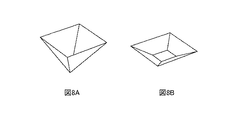
また、上記実施の形態においては、現像剤供給ローラ550に設けられた凹部として、溝550aを例に挙げて説明したが、例えば、図8Aや図8Bに示すような形状の窪みが現像剤供給ローラ550に多数設けられていることとしてもよい。なお、図8A及び図8Bは、現像剤供給ローラ550上に設けられた窪みの形状を示したものである。
ただし、凹部を簡易に加工できる点で、上記実施の形態の方がより望ましい。
In the above embodiment, the
However, the above embodiment is more preferable in that the recess can be easily processed.
また、上記実施の形態において、現像剤供給ローラ550は、現像ローラ510が圧接部510aにて現像剤供給ローラ550の表面に圧接した状態で、現像ローラ510に現像剤Dを供給し、現像ローラ510の圧接部510aの算術平均高さRaは、前記溝550aの算術平均高さRaよりも大きいこととしたが、これに限定されるものではない。例えば、圧接部510aの算術平均高さRaは、溝550aの算術平均高さRaよりも小さいこととしてもよい。
In the above embodiment, the
現像剤Dは、算術平均高さRaが互いに異なる二つの部材が圧接した状況においては、算術平均高さRaが小さい部材(現像剤Dが離れ易い部材)から算術平均高さRaが大きい部材(現像剤Dが付着し易い部材)へ移動しやすくなる。したがって、圧接部510aの算術平均高さRaが、溝550aの算術平均高さRaよりも大きい場合には、現像剤供給ローラ550の溝550aから現像ローラ510へ現像剤Dが適切に供給されることとなり、かかる点で、上記実施の形態の方がより望ましい。
In a situation where two members having different arithmetic average heights Ra are pressed against each other, the developer D is a member having a large arithmetic average height Ra from a member having a small arithmetic average height Ra (a member from which the developer D is easily separated). It becomes easy to move to the member to which the developer D easily adheres. Therefore, when the arithmetic average height Ra of the
また、上記実施の形態において、非溝部550bの算術平均高さRaは、現像ローラ510の圧接部510aの算術平均高さRaよりも小さいこととしたが、これに限定されるものではない。例えば、非溝部550bの算術平均高さRaが、現像ローラ510の圧接部510aの算術平均高さRaよりも大きいこととしてもよい。
ただし、非溝部550bが圧接部510aを損傷させること、を適切に防止することができる点で、上記実施の形態の方がより望ましい。
In the above embodiment, the arithmetic average height Ra of the
However, the above embodiment is more preferable in that the
また、上記実施の形態において、規制ブレード560の前記当接部560aの算術平均高さRaは、前記溝550aの算術平均高さRaよりも小さいこととしたが、これに限定されるものではない。例えば、当接部560aの算術平均高さRaが、溝550aの算術平均高さRaよりも大きいこととしてもよい。
In the above embodiment, the arithmetic average height Ra of the
また、上記実施の形態において、前記現像剤Dは、非ニュートン流体であることとしたが、これに限定されるものではない。例えば、現像剤Dは、ニュートン流体であることとしてもよい。 In the above embodiment, the developer D is a non-Newtonian fluid. However, the present invention is not limited to this. For example, the developer D may be a Newtonian fluid.
===画像形成システム等の構成===
次に、本発明に係る実施の形態の一例である画像形成システムの実施形態について、図面を参照しながら説明する。
=== Configuration of Image Forming System etc. ===
Next, an image forming system according to an embodiment of the present invention will be described with reference to the drawings.
図9は、画像形成システムの外観構成を示した説明図である。画像形成システム700は、コンピュータ702と、表示装置704と、プリンタ706と、入力装置708と、読取装置710とを備えている。コンピュータ702は、本実施形態ではミニタワー型の筐体に収納されているが、これに限られるものではない。表示装置704は、CRT(Cathode Ray Tube:陰極線管)やプラズマディスプレイや液晶表示装置等が用いられるのが一般的であるが、これに限られるものではない。プリンタ706は、上記に説明されたプリンタが用いられている。入力装置708は、本実施形態ではキーボード708Aとマウス708Bが用いられているが、これに限られるものではない。読取装置710は、本実施形態ではフレキシブルディスクドライブ装置710AとCD−ROMドライブ装置710Bが用いられているが、これに限られるものではなく、例えばMO(Magneto Optical)ディスクドライブ装置やDVD(Digital Versatile Disk)等の他のものであっても良い。
FIG. 9 is an explanatory diagram showing an external configuration of the image forming system. The
図10は、図9に示した画像形成システムの構成を示すブロック図である。コンピュータ702が収納された筐体内にRAM等の内部メモリ802と、ハードディスクドライブユニット804等の外部メモリがさらに設けられている。
FIG. 10 is a block diagram showing the configuration of the image forming system shown in FIG. An
なお、以上の説明においては、プリンタ706が、コンピュータ702、表示装置704、入力装置708、及び、読取装置710と接続されて画像形成システムを構成した例について説明したが、これに限られるものではない。例えば、画像形成システムが、コンピュータ702とプリンタ706から構成されても良く、画像形成システムが表示装置704、入力装置708及び読取装置710のいずれかを備えていなくても良い。
In the above description, the example in which the
また、例えば、プリンタ706が、コンピュータ702、表示装置704、入力装置708、及び、読取装置710のそれぞれの機能又は機構の一部を持っていても良い。一例として、プリンタ706が、画像処理を行う画像処理部、各種の表示を行う表示部、及び、デジタルカメラ等により撮影された画像データを記録した記録メディアを着脱するための記録メディア着脱部等を有する構成としても良い。
For example, the
このようにして実現された画像形成システムは、システム全体として従来システムよりも優れたシステムとなる。 The image forming system realized in this way is a system superior to the conventional system as a whole system.
10 レーザビームプリンタ
15Y、15M、15C、15K 現像部
20Y、20M、20C、20K 感光体
30Y、30M、30C、30K 帯電ユニット
40Y、40M、40C、40K 露光ユニット
50Y、50M、50C、50K 現像ユニット
60Y、60M、60C、60K 一次転写ユニット
70 中間転写体
73Y、73M、73C、73K 除電ユニット
75Y、75M、75C、75K 感光体クリーニングユニット
76Y、76M、76C、76K 感光体クリーニングブレード
80 二次転写ユニット
100 制御ユニット 101 メインコントローラ
102 ユニットコントローラ 112 インターフェイス
113 画像メモリ
510 現像ローラ 510a 圧接部
530 現像剤収容部 540 現像剤汲み上げローラ
550 現像剤供給ローラ
550a 溝 550b 非溝部
560 規制ブレード 560a 当接部
562 規制ブレード支持部材
570 現像ローラクリーニングユニット
571 現像ローラクリーニングブレード
700 画像形成システム 702 コンピュータ
704 表示装置 706 プリンタ
708 入力装置
708A キーボード 708B マウス
710 読取装置
710A フレキシブルディスクドライブ装置
710B CD−ROMドライブ装置
802 内部メモリ
804 ハードディスクドライブユニット
D 現像剤
B バイト
10
B bytes
Claims (4)
凹部と、算術平均高さが前記凹部の算術平均高さよりも大きい非凹部と、を表面に有し、前記凹部に保持された液体現像剤を前記現像剤担持体に供給するための現像剤供給部材と、
前記現像剤供給部材の前記表面に当接して前記現像剤供給部材上の液体現像剤の量を規制するための規制部材と、
を有し、
前記現像剤供給部材は、前記現像剤担持体が圧接部にて該現像剤供給部材の前記表面に圧接した状態で、該現像剤担持体に液体現像剤を供給し、
前記現像剤担持体の前記圧接部の算術平均高さは、前記凹部の算術平均高さよりも大きいことを特徴とする現像装置。 A developer carrier for carrying a liquid developer;
A developer supply for supplying a liquid developer held in the recess to the developer carrier, the recess having a recess and a non-recess having an arithmetic average height larger than the arithmetic average height of the recess. Members,
A regulating member for regulating the amount of liquid developer on the developer supply member in contact with the surface of the developer supply member;
Have
The developer supply member supplies a liquid developer to the developer carrier in a state where the developer carrier is in pressure contact with the surface of the developer supply member at a pressure contact portion,
The developing device according to claim 1, wherein an arithmetic average height of the press contact portion of the developer carrying member is larger than an arithmetic average height of the concave portion .
前記非凹部の算術平均高さは、前記現像剤担持体の前記圧接部の算術平均高さよりも小さいことを特徴とする現像装置。 The developing device according to claim 1,
The developing device according to claim 1, wherein the arithmetic average height of the non-concave portion is smaller than the arithmetic average height of the press contact portion of the developer carrier.
前記規制部材の、前記表面へ当接する当接部、の算術平均高さは、前記凹部の算術平均高さよりも小さいことを特徴とする現像装置。 In the developing device according to claim 1 or 2,
The developing device according to claim 1, wherein an arithmetic average height of a contact portion of the restricting member that contacts the surface is smaller than an arithmetic average height of the concave portion.
凹部と、算術平均高さが前記凹部の算術平均高さよりも大きい非凹部と、を表面に有し、前記凹部に保持された液体現像剤を前記現像剤担持体に供給するための現像剤供給部材と、
前記現像剤供給部材の前記表面に当接して前記現像剤供給部材上の液体現像剤の量を規制するための規制部材と、
を有し、
前記現像剤担持体と、前記現像剤供給部材は、それぞれ、円柱状の現像剤担持ローラと、円柱状の現像剤供給ローラであり、
前記凹部は、溝であり、
前記現像剤供給部材は、前記現像剤担持体が圧接部にて該現像剤供給部材の前記表面に圧接した状態で、該現像剤担持体に液体現像剤を供給し、前記現像剤担持体の前記圧接部の算術平均高さは、前記凹部の算術平均高さよりも大きくて、
前記非凹部の算術平均高さは、前記現像剤担持体の前記圧接部の算術平均高さよりも小さくて、
前記規制部材の、前記表面へ当接する当接部、の算術平均高さは、前記凹部の算術平均高さよりも小さくて、
前記液体現像剤は、非ニュートン流体であることを特徴とする現像装置。 A developer carrier for carrying a liquid developer;
A developer supply for supplying a liquid developer held in the recess to the developer carrier, the recess having a recess and a non-recess having an arithmetic average height larger than the arithmetic average height of the recess. Members,
A regulating member for regulating the amount of liquid developer on the developer supply member in contact with the surface of the developer supply member;
Have
The developer carrier and the developer supply member are respectively a cylindrical developer carrying roller and a cylindrical developer supply roller,
The recess is a groove;
The developer supply member supplies a liquid developer to the developer carrier in a state where the developer carrier is in pressure contact with the surface of the developer supply member at a pressure contact portion, and the developer carrier The arithmetic average height of the pressure contact portion is larger than the arithmetic average height of the concave portion,
The arithmetic average height of the non-concave portion is smaller than the arithmetic average height of the pressure contact portion of the developer carrier,
The arithmetic average height of the contact portion of the regulating member that contacts the surface is smaller than the arithmetic average height of the concave portion,
The developing device, wherein the liquid developer is a non-Newtonian fluid.
Priority Applications (1)
| Application Number | Priority Date | Filing Date | Title |
|---|---|---|---|
| JP2004305860A JP4635556B2 (en) | 2004-10-20 | 2004-10-20 | Developing device, image forming apparatus, and image forming system |
Applications Claiming Priority (1)
| Application Number | Priority Date | Filing Date | Title |
|---|---|---|---|
| JP2004305860A JP4635556B2 (en) | 2004-10-20 | 2004-10-20 | Developing device, image forming apparatus, and image forming system |
Related Child Applications (1)
| Application Number | Title | Priority Date | Filing Date |
|---|---|---|---|
| JP2010215663A Division JP4858640B2 (en) | 2010-09-27 | 2010-09-27 | Developing device and image forming apparatus |
Publications (2)
| Publication Number | Publication Date |
|---|---|
| JP2006119281A JP2006119281A (en) | 2006-05-11 |
| JP4635556B2 true JP4635556B2 (en) | 2011-02-23 |
Family
ID=36537241
Family Applications (1)
| Application Number | Title | Priority Date | Filing Date |
|---|---|---|---|
| JP2004305860A Expired - Fee Related JP4635556B2 (en) | 2004-10-20 | 2004-10-20 | Developing device, image forming apparatus, and image forming system |
Country Status (1)
| Country | Link |
|---|---|
| JP (1) | JP4635556B2 (en) |
Families Citing this family (2)
| Publication number | Priority date | Publication date | Assignee | Title |
|---|---|---|---|---|
| JP2008058870A (en) * | 2006-09-04 | 2008-03-13 | Mitsubishi Cable Ind Ltd | Measuring roller |
| JP2015179196A (en) * | 2014-03-19 | 2015-10-08 | 富士ゼロックス株式会社 | Supply member and image forming apparatus |
Family Cites Families (3)
| Publication number | Priority date | Publication date | Assignee | Title |
|---|---|---|---|---|
| JP3826455B2 (en) * | 1996-06-20 | 2006-09-27 | ソニー株式会社 | Gravure coating apparatus and manufacturing method thereof |
| JP2000321876A (en) * | 1999-05-11 | 2000-11-24 | Ricoh Co Ltd | Wet image forming device |
| JP2002278291A (en) * | 2001-03-22 | 2002-09-27 | Ricoh Co Ltd | Liquid developing device and liquid image forming device |
-
2004
- 2004-10-20 JP JP2004305860A patent/JP4635556B2/en not_active Expired - Fee Related
Also Published As
| Publication number | Publication date |
|---|---|
| JP2006119281A (en) | 2006-05-11 |
Similar Documents
| Publication | Publication Date | Title |
|---|---|---|
| US7403736B2 (en) | Image forming apparatus, image forming system, and image forming method | |
| JP4635556B2 (en) | Developing device, image forming apparatus, and image forming system | |
| JP4507683B2 (en) | Liquid development equipment | |
| JP4858640B2 (en) | Developing device and image forming apparatus | |
| JP4432415B2 (en) | Liquid developing device, image forming apparatus, and image forming system | |
| JP4363121B2 (en) | Liquid developing device, image forming apparatus, and image forming system | |
| JP4461884B2 (en) | Developing device, image forming apparatus, and image forming system | |
| JP4363135B2 (en) | Liquid developing device, image forming apparatus, and image forming system | |
| JP4419473B2 (en) | Image forming apparatus, image forming system, and image forming method | |
| JP4609033B2 (en) | Developing device, image forming apparatus, and image forming system | |
| JP4479187B2 (en) | Developing device and image forming apparatus | |
| JP4461883B2 (en) | Liquid developing device, image forming apparatus, and image forming system | |
| JP4513401B2 (en) | Developing device and image forming apparatus | |
| US7167666B2 (en) | Liquid development device, image forming apparatus, and image forming system | |
| JP4363122B2 (en) | Liquid developing device, image forming apparatus, and image forming system | |
| JP4289077B2 (en) | Image forming apparatus, image forming system, and image forming method | |
| JP4635565B2 (en) | Liquid developing device and image forming apparatus | |
| JP4581623B2 (en) | Liquid developing device, image forming apparatus, image forming system, and developer supply roller | |
| JP4572563B2 (en) | Developing device, image forming apparatus, and image forming system | |
| JP2007240634A (en) | Image forming apparatus and image forming system | |
| JP4882901B2 (en) | Image forming apparatus, image forming system, and image forming method | |
| JP2005070184A (en) | Developing device, regulating member, image forming apparatus, and image forming system | |
| JP2005292638A (en) | Developing device, image forming apparatus, and image forming system | |
| JP2006030639A (en) | Developing device, developer supply roller, image forming apparatus, and image forming system | |
| JP2005316114A (en) | Developing device, image forming apparatus, and image forming system |
Legal Events
| Date | Code | Title | Description |
|---|---|---|---|
| A621 | Written request for application examination |
Free format text: JAPANESE INTERMEDIATE CODE: A621 Effective date: 20071005 |
|
| A977 | Report on retrieval |
Free format text: JAPANESE INTERMEDIATE CODE: A971007 Effective date: 20100628 |
|
| A131 | Notification of reasons for refusal |
Free format text: JAPANESE INTERMEDIATE CODE: A131 Effective date: 20100803 |
|
| A521 | Request for written amendment filed |
Free format text: JAPANESE INTERMEDIATE CODE: A523 Effective date: 20100927 |
|
| TRDD | Decision of grant or rejection written | ||
| A01 | Written decision to grant a patent or to grant a registration (utility model) |
Free format text: JAPANESE INTERMEDIATE CODE: A01 Effective date: 20101026 |
|
| A01 | Written decision to grant a patent or to grant a registration (utility model) |
Free format text: JAPANESE INTERMEDIATE CODE: A01 |
|
| A61 | First payment of annual fees (during grant procedure) |
Free format text: JAPANESE INTERMEDIATE CODE: A61 Effective date: 20101108 |
|
| FPAY | Renewal fee payment (event date is renewal date of database) |
Free format text: PAYMENT UNTIL: 20131203 Year of fee payment: 3 |
|
| R150 | Certificate of patent or registration of utility model |
Free format text: JAPANESE INTERMEDIATE CODE: R150 |
|
| LAPS | Cancellation because of no payment of annual fees |